JP7612974B2 - Electronics - Google Patents
ElectronicsDownload PDFInfo
- Publication number
- JP7612974B2 JP7612974B2JP2020195712AJP2020195712AJP7612974B2JP 7612974 B2JP7612974 B2JP 7612974B2JP 2020195712 AJP2020195712 AJP 2020195712AJP 2020195712 AJP2020195712 AJP 2020195712AJP 7612974 B2JP7612974 B2JP 7612974B2
- Authority
- JP
- Japan
- Prior art keywords
- die
- bridge
- pads
- substrate
- electronic device
- Prior art date
- Legal status (The legal status is an assumption and is not a legal conclusion. Google has not performed a legal analysis and makes no representation as to the accuracy of the status listed.)
- Active
Links
Images
Classifications
- H—ELECTRICITY
- H01—ELECTRIC ELEMENTS
- H01L—SEMICONDUCTOR DEVICES NOT COVERED BY CLASS H10
- H01L25/00—Assemblies consisting of a plurality of semiconductor or other solid state devices
- H01L25/16—Assemblies consisting of a plurality of semiconductor or other solid state devices the devices being of types provided for in two or more different subclasses of H10B, H10D, H10F, H10H, H10K or H10N, e.g. forming hybrid circuits
- H—ELECTRICITY
- H01—ELECTRIC ELEMENTS
- H01L—SEMICONDUCTOR DEVICES NOT COVERED BY CLASS H10
- H01L23/00—Details of semiconductor or other solid state devices
- H01L23/48—Arrangements for conducting electric current to or from the solid state body in operation, e.g. leads, terminal arrangements ; Selection of materials therefor
- H01L23/482—Arrangements for conducting electric current to or from the solid state body in operation, e.g. leads, terminal arrangements ; Selection of materials therefor consisting of lead-in layers inseparably applied to the semiconductor body (electrodes)
- H01L23/4821—Bridge structure with air gap
- H—ELECTRICITY
- H01—ELECTRIC ELEMENTS
- H01L—SEMICONDUCTOR DEVICES NOT COVERED BY CLASS H10
- H01L23/00—Details of semiconductor or other solid state devices
- H01L23/12—Mountings, e.g. non-detachable insulating substrates
- H01L23/13—Mountings, e.g. non-detachable insulating substrates characterised by the shape
- H—ELECTRICITY
- H01—ELECTRIC ELEMENTS
- H01L—SEMICONDUCTOR DEVICES NOT COVERED BY CLASS H10
- H01L23/00—Details of semiconductor or other solid state devices
- H01L23/28—Encapsulations, e.g. encapsulating layers, coatings, e.g. for protection
- H01L23/31—Encapsulations, e.g. encapsulating layers, coatings, e.g. for protection characterised by the arrangement or shape
- H01L23/3107—Encapsulations, e.g. encapsulating layers, coatings, e.g. for protection characterised by the arrangement or shape the device being completely enclosed
- H01L23/3121—Encapsulations, e.g. encapsulating layers, coatings, e.g. for protection characterised by the arrangement or shape the device being completely enclosed a substrate forming part of the encapsulation
- H01L23/3128—Encapsulations, e.g. encapsulating layers, coatings, e.g. for protection characterised by the arrangement or shape the device being completely enclosed a substrate forming part of the encapsulation the substrate having spherical bumps for external connection
- H—ELECTRICITY
- H01—ELECTRIC ELEMENTS
- H01L—SEMICONDUCTOR DEVICES NOT COVERED BY CLASS H10
- H01L23/00—Details of semiconductor or other solid state devices
- H01L23/48—Arrangements for conducting electric current to or from the solid state body in operation, e.g. leads, terminal arrangements ; Selection of materials therefor
- H01L23/482—Arrangements for conducting electric current to or from the solid state body in operation, e.g. leads, terminal arrangements ; Selection of materials therefor consisting of lead-in layers inseparably applied to the semiconductor body (electrodes)
- H01L23/4825—Arrangements for conducting electric current to or from the solid state body in operation, e.g. leads, terminal arrangements ; Selection of materials therefor consisting of lead-in layers inseparably applied to the semiconductor body (electrodes) for devices consisting of semiconductor layers on insulating or semi-insulating substrates, e.g. silicon on sapphire devices, i.e. SOS
- H—ELECTRICITY
- H01—ELECTRIC ELEMENTS
- H01L—SEMICONDUCTOR DEVICES NOT COVERED BY CLASS H10
- H01L23/00—Details of semiconductor or other solid state devices
- H01L23/48—Arrangements for conducting electric current to or from the solid state body in operation, e.g. leads, terminal arrangements ; Selection of materials therefor
- H01L23/482—Arrangements for conducting electric current to or from the solid state body in operation, e.g. leads, terminal arrangements ; Selection of materials therefor consisting of lead-in layers inseparably applied to the semiconductor body (electrodes)
- H01L23/485—Arrangements for conducting electric current to or from the solid state body in operation, e.g. leads, terminal arrangements ; Selection of materials therefor consisting of lead-in layers inseparably applied to the semiconductor body (electrodes) consisting of layered constructions comprising conductive layers and insulating layers, e.g. planar contacts
- H—ELECTRICITY
- H01—ELECTRIC ELEMENTS
- H01L—SEMICONDUCTOR DEVICES NOT COVERED BY CLASS H10
- H01L23/00—Details of semiconductor or other solid state devices
- H01L23/48—Arrangements for conducting electric current to or from the solid state body in operation, e.g. leads, terminal arrangements ; Selection of materials therefor
- H01L23/488—Arrangements for conducting electric current to or from the solid state body in operation, e.g. leads, terminal arrangements ; Selection of materials therefor consisting of soldered or bonded constructions
- H01L23/495—Lead-frames or other flat leads
- H01L23/49503—Lead-frames or other flat leads characterised by the die pad
- H—ELECTRICITY
- H01—ELECTRIC ELEMENTS
- H01L—SEMICONDUCTOR DEVICES NOT COVERED BY CLASS H10
- H01L23/00—Details of semiconductor or other solid state devices
- H01L23/48—Arrangements for conducting electric current to or from the solid state body in operation, e.g. leads, terminal arrangements ; Selection of materials therefor
- H01L23/488—Arrangements for conducting electric current to or from the solid state body in operation, e.g. leads, terminal arrangements ; Selection of materials therefor consisting of soldered or bonded constructions
- H01L23/498—Leads, i.e. metallisations or lead-frames on insulating substrates, e.g. chip carriers
- H01L23/49811—Additional leads joined to the metallisation on the insulating substrate, e.g. pins, bumps, wires, flat leads
- H01L23/49816—Spherical bumps on the substrate for external connection, e.g. ball grid arrays [BGA]
- H—ELECTRICITY
- H01—ELECTRIC ELEMENTS
- H01L—SEMICONDUCTOR DEVICES NOT COVERED BY CLASS H10
- H01L23/00—Details of semiconductor or other solid state devices
- H01L23/52—Arrangements for conducting electric current within the device in operation from one component to another, i.e. interconnections, e.g. wires, lead frames
- H01L23/538—Arrangements for conducting electric current within the device in operation from one component to another, i.e. interconnections, e.g. wires, lead frames the interconnection structure between a plurality of semiconductor chips being formed on, or in, insulating substrates
- H01L23/5381—Crossover interconnections, e.g. bridge stepovers
- H—ELECTRICITY
- H01—ELECTRIC ELEMENTS
- H01L—SEMICONDUCTOR DEVICES NOT COVERED BY CLASS H10
- H01L23/00—Details of semiconductor or other solid state devices
- H01L23/52—Arrangements for conducting electric current within the device in operation from one component to another, i.e. interconnections, e.g. wires, lead frames
- H01L23/538—Arrangements for conducting electric current within the device in operation from one component to another, i.e. interconnections, e.g. wires, lead frames the interconnection structure between a plurality of semiconductor chips being formed on, or in, insulating substrates
- H01L23/5385—Assembly of a plurality of insulating substrates
- H—ELECTRICITY
- H01—ELECTRIC ELEMENTS
- H01L—SEMICONDUCTOR DEVICES NOT COVERED BY CLASS H10
- H01L24/00—Arrangements for connecting or disconnecting semiconductor or solid-state bodies; Methods or apparatus related thereto
- H01L24/01—Means for bonding being attached to, or being formed on, the surface to be connected, e.g. chip-to-package, die-attach, "first-level" interconnects; Manufacturing methods related thereto
- H01L24/02—Bonding areas ; Manufacturing methods related thereto
- H01L24/04—Structure, shape, material or disposition of the bonding areas prior to the connecting process
- H01L24/06—Structure, shape, material or disposition of the bonding areas prior to the connecting process of a plurality of bonding areas
- H—ELECTRICITY
- H01—ELECTRIC ELEMENTS
- H01L—SEMICONDUCTOR DEVICES NOT COVERED BY CLASS H10
- H01L24/00—Arrangements for connecting or disconnecting semiconductor or solid-state bodies; Methods or apparatus related thereto
- H01L24/01—Means for bonding being attached to, or being formed on, the surface to be connected, e.g. chip-to-package, die-attach, "first-level" interconnects; Manufacturing methods related thereto
- H01L24/02—Bonding areas ; Manufacturing methods related thereto
- H01L24/07—Structure, shape, material or disposition of the bonding areas after the connecting process
- H01L24/09—Structure, shape, material or disposition of the bonding areas after the connecting process of a plurality of bonding areas
- H—ELECTRICITY
- H01—ELECTRIC ELEMENTS
- H01L—SEMICONDUCTOR DEVICES NOT COVERED BY CLASS H10
- H01L24/00—Arrangements for connecting or disconnecting semiconductor or solid-state bodies; Methods or apparatus related thereto
- H01L24/01—Means for bonding being attached to, or being formed on, the surface to be connected, e.g. chip-to-package, die-attach, "first-level" interconnects; Manufacturing methods related thereto
- H01L24/10—Bump connectors ; Manufacturing methods related thereto
- H01L24/12—Structure, shape, material or disposition of the bump connectors prior to the connecting process
- H01L24/13—Structure, shape, material or disposition of the bump connectors prior to the connecting process of an individual bump connector
- H—ELECTRICITY
- H01—ELECTRIC ELEMENTS
- H01L—SEMICONDUCTOR DEVICES NOT COVERED BY CLASS H10
- H01L25/00—Assemblies consisting of a plurality of semiconductor or other solid state devices
- H01L25/03—Assemblies consisting of a plurality of semiconductor or other solid state devices all the devices being of a type provided for in a single subclass of subclasses H10B, H10D, H10F, H10H, H10K or H10N, e.g. assemblies of rectifier diodes
- H01L25/04—Assemblies consisting of a plurality of semiconductor or other solid state devices all the devices being of a type provided for in a single subclass of subclasses H10B, H10D, H10F, H10H, H10K or H10N, e.g. assemblies of rectifier diodes the devices not having separate containers
- H01L25/065—Assemblies consisting of a plurality of semiconductor or other solid state devices all the devices being of a type provided for in a single subclass of subclasses H10B, H10D, H10F, H10H, H10K or H10N, e.g. assemblies of rectifier diodes the devices not having separate containers the devices being of a type provided for in group H10D89/00
- H01L25/0652—Assemblies consisting of a plurality of semiconductor or other solid state devices all the devices being of a type provided for in a single subclass of subclasses H10B, H10D, H10F, H10H, H10K or H10N, e.g. assemblies of rectifier diodes the devices not having separate containers the devices being of a type provided for in group H10D89/00 the devices being arranged next and on each other, i.e. mixed assemblies
- H—ELECTRICITY
- H01—ELECTRIC ELEMENTS
- H01L—SEMICONDUCTOR DEVICES NOT COVERED BY CLASS H10
- H01L2224/00—Indexing scheme for arrangements for connecting or disconnecting semiconductor or solid-state bodies and methods related thereto as covered by H01L24/00
- H01L2224/01—Means for bonding being attached to, or being formed on, the surface to be connected, e.g. chip-to-package, die-attach, "first-level" interconnects; Manufacturing methods related thereto
- H01L2224/02—Bonding areas; Manufacturing methods related thereto
- H01L2224/023—Redistribution layers [RDL] for bonding areas
- H01L2224/0233—Structure of the redistribution layers
- H01L2224/02331—Multilayer structure
- H—ELECTRICITY
- H01—ELECTRIC ELEMENTS
- H01L—SEMICONDUCTOR DEVICES NOT COVERED BY CLASS H10
- H01L2224/00—Indexing scheme for arrangements for connecting or disconnecting semiconductor or solid-state bodies and methods related thereto as covered by H01L24/00
- H01L2224/01—Means for bonding being attached to, or being formed on, the surface to be connected, e.g. chip-to-package, die-attach, "first-level" interconnects; Manufacturing methods related thereto
- H01L2224/02—Bonding areas; Manufacturing methods related thereto
- H01L2224/023—Redistribution layers [RDL] for bonding areas
- H01L2224/0237—Disposition of the redistribution layers
- H01L2224/02381—Side view
- H—ELECTRICITY
- H01—ELECTRIC ELEMENTS
- H01L—SEMICONDUCTOR DEVICES NOT COVERED BY CLASS H10
- H01L2224/00—Indexing scheme for arrangements for connecting or disconnecting semiconductor or solid-state bodies and methods related thereto as covered by H01L24/00
- H01L2224/01—Means for bonding being attached to, or being formed on, the surface to be connected, e.g. chip-to-package, die-attach, "first-level" interconnects; Manufacturing methods related thereto
- H01L2224/10—Bump connectors; Manufacturing methods related thereto
- H01L2224/12—Structure, shape, material or disposition of the bump connectors prior to the connecting process
- H01L2224/12105—Bump connectors formed on an encapsulation of the semiconductor or solid-state body, e.g. bumps on chip-scale packages
- H—ELECTRICITY
- H01—ELECTRIC ELEMENTS
- H01L—SEMICONDUCTOR DEVICES NOT COVERED BY CLASS H10
- H01L2224/00—Indexing scheme for arrangements for connecting or disconnecting semiconductor or solid-state bodies and methods related thereto as covered by H01L24/00
- H01L2224/01—Means for bonding being attached to, or being formed on, the surface to be connected, e.g. chip-to-package, die-attach, "first-level" interconnects; Manufacturing methods related thereto
- H01L2224/10—Bump connectors; Manufacturing methods related thereto
- H01L2224/12—Structure, shape, material or disposition of the bump connectors prior to the connecting process
- H01L2224/13—Structure, shape, material or disposition of the bump connectors prior to the connecting process of an individual bump connector
- H01L2224/13001—Core members of the bump connector
- H01L2224/13005—Structure
- H01L2224/13008—Bump connector integrally formed with a redistribution layer on the semiconductor or solid-state body
- H—ELECTRICITY
- H01—ELECTRIC ELEMENTS
- H01L—SEMICONDUCTOR DEVICES NOT COVERED BY CLASS H10
- H01L2224/00—Indexing scheme for arrangements for connecting or disconnecting semiconductor or solid-state bodies and methods related thereto as covered by H01L24/00
- H01L2224/01—Means for bonding being attached to, or being formed on, the surface to be connected, e.g. chip-to-package, die-attach, "first-level" interconnects; Manufacturing methods related thereto
- H01L2224/10—Bump connectors; Manufacturing methods related thereto
- H01L2224/12—Structure, shape, material or disposition of the bump connectors prior to the connecting process
- H01L2224/14—Structure, shape, material or disposition of the bump connectors prior to the connecting process of a plurality of bump connectors
- H01L2224/1401—Structure
- H01L2224/1403—Bump connectors having different sizes, e.g. different diameters, heights or widths
- H—ELECTRICITY
- H01—ELECTRIC ELEMENTS
- H01L—SEMICONDUCTOR DEVICES NOT COVERED BY CLASS H10
- H01L2224/00—Indexing scheme for arrangements for connecting or disconnecting semiconductor or solid-state bodies and methods related thereto as covered by H01L24/00
- H01L2224/01—Means for bonding being attached to, or being formed on, the surface to be connected, e.g. chip-to-package, die-attach, "first-level" interconnects; Manufacturing methods related thereto
- H01L2224/26—Layer connectors, e.g. plate connectors, solder or adhesive layers; Manufacturing methods related thereto
- H01L2224/31—Structure, shape, material or disposition of the layer connectors after the connecting process
- H01L2224/32—Structure, shape, material or disposition of the layer connectors after the connecting process of an individual layer connector
- H01L2224/3201—Structure
- H01L2224/32012—Structure relative to the bonding area, e.g. bond pad
- H01L2224/32013—Structure relative to the bonding area, e.g. bond pad the layer connector being larger than the bonding area, e.g. bond pad
- H—ELECTRICITY
- H01—ELECTRIC ELEMENTS
- H01L—SEMICONDUCTOR DEVICES NOT COVERED BY CLASS H10
- H01L2224/00—Indexing scheme for arrangements for connecting or disconnecting semiconductor or solid-state bodies and methods related thereto as covered by H01L24/00
- H01L2224/01—Means for bonding being attached to, or being formed on, the surface to be connected, e.g. chip-to-package, die-attach, "first-level" interconnects; Manufacturing methods related thereto
- H01L2224/26—Layer connectors, e.g. plate connectors, solder or adhesive layers; Manufacturing methods related thereto
- H01L2224/31—Structure, shape, material or disposition of the layer connectors after the connecting process
- H01L2224/32—Structure, shape, material or disposition of the layer connectors after the connecting process of an individual layer connector
- H01L2224/321—Disposition
- H01L2224/32151—Disposition the layer connector connecting between a semiconductor or solid-state body and an item not being a semiconductor or solid-state body, e.g. chip-to-substrate, chip-to-passive
- H01L2224/32221—Disposition the layer connector connecting between a semiconductor or solid-state body and an item not being a semiconductor or solid-state body, e.g. chip-to-substrate, chip-to-passive the body and the item being stacked
- H01L2224/32225—Disposition the layer connector connecting between a semiconductor or solid-state body and an item not being a semiconductor or solid-state body, e.g. chip-to-substrate, chip-to-passive the body and the item being stacked the item being non-metallic, e.g. insulating substrate with or without metallisation
- H—ELECTRICITY
- H01—ELECTRIC ELEMENTS
- H01L—SEMICONDUCTOR DEVICES NOT COVERED BY CLASS H10
- H01L24/00—Arrangements for connecting or disconnecting semiconductor or solid-state bodies; Methods or apparatus related thereto
- H01L24/01—Means for bonding being attached to, or being formed on, the surface to be connected, e.g. chip-to-package, die-attach, "first-level" interconnects; Manufacturing methods related thereto
- H01L24/10—Bump connectors ; Manufacturing methods related thereto
- H01L24/15—Structure, shape, material or disposition of the bump connectors after the connecting process
- H01L24/16—Structure, shape, material or disposition of the bump connectors after the connecting process of an individual bump connector
- H—ELECTRICITY
- H01—ELECTRIC ELEMENTS
- H01L—SEMICONDUCTOR DEVICES NOT COVERED BY CLASS H10
- H01L24/00—Arrangements for connecting or disconnecting semiconductor or solid-state bodies; Methods or apparatus related thereto
- H01L24/01—Means for bonding being attached to, or being formed on, the surface to be connected, e.g. chip-to-package, die-attach, "first-level" interconnects; Manufacturing methods related thereto
- H01L24/10—Bump connectors ; Manufacturing methods related thereto
- H01L24/15—Structure, shape, material or disposition of the bump connectors after the connecting process
- H01L24/17—Structure, shape, material or disposition of the bump connectors after the connecting process of a plurality of bump connectors
- H—ELECTRICITY
- H01—ELECTRIC ELEMENTS
- H01L—SEMICONDUCTOR DEVICES NOT COVERED BY CLASS H10
- H01L24/00—Arrangements for connecting or disconnecting semiconductor or solid-state bodies; Methods or apparatus related thereto
- H01L24/01—Means for bonding being attached to, or being formed on, the surface to be connected, e.g. chip-to-package, die-attach, "first-level" interconnects; Manufacturing methods related thereto
- H01L24/26—Layer connectors, e.g. plate connectors, solder or adhesive layers; Manufacturing methods related thereto
- H01L24/31—Structure, shape, material or disposition of the layer connectors after the connecting process
- H01L24/32—Structure, shape, material or disposition of the layer connectors after the connecting process of an individual layer connector
- H—ELECTRICITY
- H01—ELECTRIC ELEMENTS
- H01L—SEMICONDUCTOR DEVICES NOT COVERED BY CLASS H10
- H01L2924/00—Indexing scheme for arrangements or methods for connecting or disconnecting semiconductor or solid-state bodies as covered by H01L24/00
- H01L2924/15—Details of package parts other than the semiconductor or other solid state devices to be connected
- H01L2924/151—Die mounting substrate
- H01L2924/1515—Shape
- H01L2924/15153—Shape the die mounting substrate comprising a recess for hosting the device
Landscapes
- Engineering & Computer Science (AREA)
- Microelectronics & Electronic Packaging (AREA)
- Power Engineering (AREA)
- Computer Hardware Design (AREA)
- Physics & Mathematics (AREA)
- Condensed Matter Physics & Semiconductors (AREA)
- General Physics & Mathematics (AREA)
- Wire Bonding (AREA)
- Combinations Of Printed Boards (AREA)
- Production Of Multi-Layered Print Wiring Board (AREA)
Description
Translated fromJapanese本開示の実施形態は、半導体デバイスに関し、より詳細には、オープンキャビティブリッジを有するマルチダイパッケージに関する。Embodiments of the present disclosure relate to semiconductor devices, and more particularly to multi-die packages having open cavity bridges.
フォームファクタの微細化、および高性能のための集積レベル向上への需要により、半導体業界におけるパッケージング手法の複雑化が推し進められている。そのような手法の1つは、小さいフォームファクタの微細化および高性能を可能にするために、ダイのパーティション分割を使用することである。そのようなアーキテクチャは、パーティション分割されたダイを結合するための、ダイ間の精巧な相互接続に依存する。埋込み式マルチダイ相互接続ブリッジ(embedded multi-die interconnect bridge:EMIB)が、ダイ間の精巧な相互接続を提供するために用いられてきた。しかしながら、EMIBにも、集積化におけるそれ独自の課題がある。The demand for smaller form factors and higher integration levels for higher performance is driving more complex packaging techniques in the semiconductor industry. One such technique is the use of die partitioning to enable smaller form factors and higher performance. Such architectures rely on sophisticated interconnects between the die to join the partitioned dies. Embedded multi-die interconnect bridges (EMIBs) have been used to provide sophisticated interconnects between the dies. However, EMIBs also have their own integration challenges.
1つの課題は、EMIBが、累積するバンプ厚みのばらつき(bump thickness variation:BTV)が大きいことにより損なわれることである。より多くのEMIBがパッケージに含まれるにしたがい、かつEMIBのサイズが増大するにしたがって、BTVはさらに大きい設計上の障害となりつつある。BTVを低減し、反りを改善するために、EMIBをガラスパッチに配置することが提案されている。しかしながら、ガラスパッチは熱伝導率が低い厚い基板である。したがって、熱圧着(thermocompression bonding:TCB)は中間レベル相互接続(mid-level interconnect:MLI)に適していない。したがって、従来のチップアタッチモジュール(マスリフロー)プロセスなどの代替の接合法に対応するために、MLIのピッチを増大させる必要がある。MLIのピッチを増大させることは、ガラスパッチ上に配される、1または複数の再配線層の使用を必要とする。再配線層は、ガラスによって提供されるBTVの恩恵を無効にし、望ましい解決法ではない。One challenge is that the EMIB is compromised by a large cumulative bump thickness variation (BTV). As more EMIBs are included in a package and as the size of the EMIB increases, BTV is becoming an even larger design obstacle. To reduce BTV and improve warpage, it has been proposed to place the EMIB on a glass patch. However, the glass patch is a thick substrate with low thermal conductivity. Therefore, thermocompression bonding (TCB) is not suitable for mid-level interconnect (MLI). Therefore, the pitch of the MLI needs to be increased to accommodate alternative bonding methods such as the conventional chip attach module (mass reflow) process. Increasing the pitch of the MLI requires the use of one or more redistribution layers disposed on the glass patch. A redistribution layer would negate the BTV benefits provided by the glass and is not a desirable solution.
本明細書で説明されるのは、様々な実施形態による、オープンキャビティブリッジを有するマルチダイパッケージである。以下の説明において、例証的な実装の様々な態様を、当業者が他の当業者に自らの仕事の内容を伝えるために通常用いる用語を使用して説明する。しかしながら、本開示が、説明される態様のいくつかのみによって実践され得ることは、当業者には明らかとなろう。説明の目的で、具体的な数、材料、および構成は、例証的な実装の十分な理解を提供するために記載される。しかしながら、本開示が具体的な詳細がなくとも実践され得ることは、当業者には明らかとなろう。他の例において、例証的な実装を不明瞭にしないために、周知の特徴は省略されるか、または簡略にされる。Described herein are multi-die packages with open cavity bridges, according to various embodiments. In the following description, various aspects of the illustrative implementations are described using terms that those skilled in the art typically use to convey the substance of their work to others skilled in the art. However, it will be apparent to one skilled in the art that the present disclosure may be practiced with only some of the described aspects. For purposes of explanation, specific numbers, materials, and configurations are set forth to provide a thorough understanding of the illustrative implementations. However, it will be apparent to one skilled in the art that the present disclosure may be practiced without the specific details. In other instances, well-known features are omitted or simplified so as not to obscure the illustrative implementations.
様々な操作を、複数の個別の操作として、ひいては本開示の理解を最も容易にする方法で、説明するが、その説明の順序により、これらの操作が必ず順序に依存することが含意されるものと解釈されるべきではない。具体的には、これらの操作は、提示の順序で実施する必要はない。Although the various operations are described as multiple separate operations and in a manner that best facilitates understanding of the present disclosure, the order of description should not be construed to imply that the operations are necessarily order dependent. In particular, the operations need not be performed in the order presented.
ある特定の術語も、以下の説明において参照目的のみで使用される場合があり、したがって、限定的であることを意図するものではない。たとえば、「上部の」、「下部の」、「上方の」、および「下方の」などの用語は、参照される図面における方向を指す。「前部」、「後部」、「背面」、および「側面」などの用語は、考察中の構成要素を説明するテキストおよび関連する図面の参照によって明確にされる、矛盾はないが恣意的な基準枠内で、構成要素の部分の向きおよび/または位置を説明する。このような術語は、具体的に上に述べた単語、それらの派生語、および類似の意味の単語を含む場合がある。Certain terminology may also be used in the following description for reference purposes only and is therefore not intended to be limiting. For example, terms such as "upper," "lower," "upper," and "lower" refer to directions in the drawings to which reference is made. Terms such as "front," "rear," "back," and "side" describe the orientation and/or location of parts of a component within a consistent but arbitrary frame of reference made clear by reference to the text describing the component under consideration and the associated drawings. Such terminology may include the words specifically mentioned above, derivatives thereof, and words of similar meaning.
上で言及したように、パーティション分割されたダイのアーキテクチャは、パーティション分割されたダイを結合するために用いられる相互接続アーキテクチャによって、少なくとも一部分において限定される。たとえば、埋込み式マルチダイ相互接続ブリッジ(EMIB)アーキテクチャの使用は、バンプ厚みのばらつき(BTV)を考慮することによって限定される。ガラスパッチを使用することによってEMIBアーキテクチャにおけるBTVを改善する試みは今日まで成功していない。特に、ガラスパッチは中間レベル相互接続(mid-level interconnect:MLI)のためのマスリフロー手法の使用を必要とする。マスリフロー法ではより大きいバンプピッチが必要となるため、ピッチの移行を吸収するために再配線層(RDL)をガラスパッチに加えなければならない。RDLは厚みの均一性に悪影響を及ぼし、ガラスパッチを使用する恩恵を無効にする。As mentioned above, partitioned die architectures are limited, at least in part, by the interconnect architecture used to join the partitioned die. For example, the use of embedded multi-die interconnect bridge (EMIB) architectures is limited by bump thickness variation (BTV) considerations. Attempts to improve BTV in EMIB architectures by using glass patches have been unsuccessful to date. In particular, glass patches require the use of mass reflow techniques for mid-level interconnects (MLIs). Because mass reflow techniques require larger bump pitches, redistribution layers (RDLs) must be added to the glass patches to accommodate pitch transitions. The RDLs adversely affect thickness uniformity, negating the benefits of using glass patches.
したがって、本明細書で開示される実施形態は、オープンキャビティブリッジを含む電子パッケージを含む。オープンキャビティブリッジは、受動相互接続を含むことができ、場合により、トランジスタなどを伴う能動領域を含んでよい。Thus, embodiments disclosed herein include electronic packages that include an open cavity bridge. The open cavity bridge may include passive interconnects and, in some cases, active regions with transistors and the like.
本明細書において説明される1または複数の実施形態は、オープンキャビティブリッジ電力供給による解決法を対象とする。本明細書で説明されるオープンキャビティブリッジアーキテクチャは、接続された複数のダイに適していると同時に、より低いコスト、高い帯域幅の解決法を提供することができる。例において、埋込み式ブリッジアーキテクチャと比較して、オープンキャビティブリッジは典型的に、ブリッジの上部に表面ルーティングを有しない。本明細書で説明される実施形態は、そのような問題に対処するために実装することができる。One or more embodiments described herein are directed to an open cavity bridge power supply solution. The open cavity bridge architecture described herein can provide a lower cost, high bandwidth solution while being suitable for multiple connected dies. In examples, compared to embedded bridge architectures, open cavity bridges typically do not have surface routing on the top of the bridge. The embodiments described herein can be implemented to address such issues.
文脈を与えると、先の解決法は、(a)ダイ内部のルーティングを有する電力ルーティングを可能にすること(これはシリコン内部の薄いトレースに起因する高い抵抗を引き起こす場合がある)、(b)ワイヤボンドによる解決法、または(c)ブリッジダイをパッケージ基板ルーティングに接続するためのシリコン貫通ビア(TSV)による解決法を含む。To give context, previous solutions include (a) enabling power routing with internal die routing (which can lead to high resistance due to thin traces inside the silicon), (b) a wirebond solution, or (c) a through silicon via (TSV) solution to connect the bridge die to the package substrate routing.
本明細書で説明される実施形態に従って、いくつかの電力供給アーキテクチャが本明細書で開示され、当該アーキテクチャは、(1)導電性材料を充填したモールド/アンダーフィルトレンチを介した電力供給、(2)ブリッジをパッケージ基板ルーティングに接続する、半田/電気的接続した長いワイヤまたはコンポーネントを介した電力供給、および(3)電力供給のために基板キャビティに電気的に接続する露出された側面を有するブリッジを含む。本明細書で説明される実施形態を実装する利点は、(1)トップダイのシリコン内ルーティングに依存しない、トップダイへの(たとえば、ブリッジで結合されるロジック/メモリダイへの)電力供給、および/または(2)強い接続性および電力供給を有する、より大きいブリッジダイを可能にすることを含み得る。In accordance with the embodiments described herein, several power delivery architectures are disclosed herein, including (1) power delivery through mold/underfill trenches filled with conductive material, (2) power delivery through long solder/electrically connected wires or components connecting the bridge to the package substrate routing, and (3) bridges with exposed sides that electrically connect to the substrate cavity for power delivery. Advantages of implementing the embodiments described herein may include (1) power delivery to the top die (e.g., to a logic/memory die coupled with a bridge) that does not rely on the in-silicon routing of the top die, and/or (2) enabling a larger bridge die with strong connectivity and power delivery.
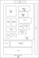
第1の態様において、レーザトレンチを使用して、オープンキャビティブリッジアーキテクチャのための電力供給位置を提供する。たとえば、レーザ形成されるトレンチは、ブリッジの上でロジックダイ間である位置に形成される。レーザトレンチは、ダイ間のアンダーフィル材料中またはダイ間のモールド中に形成され得る。トレンチは、ブリッジパッドまたはバンプを露出するように形成される。次に、トレンチは、印刷された導電性接着剤(たとえば、銅または銀の入った)または半田で充填され得る。トレンチは、電力が基板を通して供給される基板上部へのビアを有する、ダイ実装面積の外側の位置へ「引かれ」得る。例として、図1および図2は、本開示の実施形態によるオープンキャビティブリッジを有する電子パッケージを製造する方法における様々な操作を表す断面図である。図3は、本開示の別の実施形態による、図2の電子パッケージの例示的なレイアウトの平面図である。In a first aspect, a laser trench is used to provide a power supply location for an open cavity bridge architecture. For example, a laser formed trench is formed at a location between the logic dies above the bridge. The laser trench can be formed in the underfill material between the dies or in the mold between the dies. The trench is formed to expose the bridge pad or bump. The trench can then be filled with a printed conductive adhesive (e.g., copper or silver loaded) or solder. The trench can be "pulled" to a location outside the die footprint with vias to the top of the substrate where power is supplied through the substrate. By way of example, FIGS. 1 and 2 are cross-sectional views depicting various operations in a method of manufacturing an electronic package with an open cavity bridge according to an embodiment of the present disclosure. FIG. 3 is a plan view of an exemplary layout of the electronic package of FIG. 2 according to another embodiment of the present disclosure.
図1を参照すると、中間電子装置100は、交互する金属化層108と絶縁層109とを有するパッケージ基板102を含む。パッケージ基板102はまた、第1の複数の基板パッド(左112)および第2の複数の基板パッド(右112)を含み、基板パッドは、導電性ビア110によって金属化層108に結合されてよい。オープンキャビティ106は、第1の複数の基板パッド(左112)と第2の複数の基板パッド(右112)との間にある。オープンキャビティ106は、底面および側面を有する。ブリッジダイ104は、オープンキャビティ106の中にある。ブリッジダイ104は、第1の複数のブリッジパッド(左122)、第2の複数のブリッジパッド(右122)、第1の複数のブリッジパッド(左122)と第2の複数のブリッジパッド(右122)との間にある電力供給ブリッジパッド123、および導電性トレース(描写されていない)を含む。半田構造体114は、基板パッド112に結合され、半田構造体114の間に半田レジスト113が含まれてよい。半田構造体124は、ブリッジパッド122に結合される。第1のダイ130は、たとえば、第1のダイパッド132Aおよび132Bによって、それぞれ、第1の複数の基板パッド(左112)上の半田構造体114に、および第1の複数のブリッジパッド(左122)上の半田構造体124に結合される。第2のダイ134は、たとえば、第2のダイパッド136Aおよび136Bによって、それぞれ、第2の複数の基板パッド(右112)上の半田構造体114に、および第2の複数のブリッジパッド(右122)上の半田構造体124に結合される。第2のダイ134は、ブリッジダイ104の導電性トレースによって第1のダイ130に結合される。1, the intermediate electronic device 100 includes a package substrate 102 having alternating metallization layers 108 and insulating layers 109. The package substrate 102 also includes a first plurality of substrate pads (left 112) and a second plurality of substrate pads (right 112), which may be coupled to the metallization layer 108 by conductive vias 110. An open cavity 106 is between the first plurality of substrate pads (left 112) and the second plurality of substrate pads (right 112). The open cavity 106 has a bottom and a side. A bridge die 104 is within the open cavity 106. The bridge die 104 includes a first plurality of bridge pads (left 122), a second plurality of bridge pads (right 122), a power supply bridge pad 123 between the first plurality of bridge pads (left 122) and the second plurality of bridge pads (right 122), and conductive traces (not depicted). The solder structures 114 are coupled to the substrate pads 112, and solder resist 113 may be included between the solder structures 114. The solder structures 124 are coupled to the bridge pads 122. The first die 130 is coupled to the solder structures 114 on the first plurality of substrate pads (left 112) and to the solder structures 124 on the first plurality of bridge pads (left 122), for example, by first die pads 132A and 132B, respectively. The second die 134 is coupled to the solder structures 114 on the second plurality of substrate pads (right 112) and to the solder structures 124 on the second plurality of bridge pads (right 122), for example, by second die pads 136A and 136B, respectively. The second die 134 is coupled to the first die 130 by the conductive traces of the bridge die 104.
ある実施形態において、中間電子装置100は、第1のダイ130とパッケージ基板102との間、第1のダイ130とブリッジダイ104との間、第2のダイ134とパッケージ基板102との間、第2のダイ134とブリッジダイ104との間、およびオープンキャビティ106中に、アンダーフィル材料140をさらに含む。ある実施形態において、トレンチ142は、第1のダイ130と第2のダイ134との間で、アンダーフィル材料140中に形成される。一実施形態において、トレンチ142は、レーザアブレーションまたはレーザスクライブプロセスを用いて形成される。In one embodiment, the intermediate electronic device 100 further includes an underfill material 140 between the first die 130 and the package substrate 102, between the first die 130 and the bridge die 104, between the second die 134 and the package substrate 102, between the second die 134 and the bridge die 104, and in the open cavity 106. In one embodiment, a trench 142 is formed in the underfill material 140 between the first die 130 and the second die 134. In one embodiment, the trench 142 is formed using a laser ablation or laser scribing process.
ある実施形態において、エポキシドット116は、パッケージ基板102のオープンキャビティ106の底面に、ブリッジダイ104を結合する。そのような一実施形態において、描写されるように、エポキシドット116は、パッケージ基板102の露出された金属化層108に結合される。他の実施形態において、エポキシドット116は、パッケージ基板102の絶縁層109に結合される。別の実施形態において、接着層は、ブリッジダイ104をオープンキャビティ106の底面に結合し、その例示的な構造は、図7A~図7Cと関連させて、以下に説明する。さらに別の実施形態において、半田構造体は、ブリッジダイ104をオープンキャビティ106の底面に結合し、その例示的な構造は、図7Dと関連させて、以下に説明する。そのような一実施形態において、オープンキャビティ106の底面は、露出された金属層(たとえば、金属化層108のうちの1つ)を有し、ブリッジダイ104は、第1の複数のブリッジパッド(左122)、第2の複数のブリッジパッド(右122)、電力供給ブリッジパッド123、および導電性トレースを含む第1の側面を有する。ブリッジダイ104は、金属化層を含む第2の側面を有し、半田構造体はブリッジダイ104の金属化層に接触しており、オープンキャビティ106の底面の露出された金属層に接触している。In one embodiment, epoxy dots 116 bond the bridge die 104 to the bottom surface of the open cavity 106 of the package substrate 102. In one such embodiment, the epoxy dots 116 are bonded to the exposed metallization layer 108 of the package substrate 102 as depicted. In another embodiment, the epoxy dots 116 are bonded to the insulating layer 109 of the package substrate 102. In another embodiment, an adhesive layer bonds the bridge die 104 to the bottom surface of the open cavity 106, an exemplary structure of which is described below in connection with Figures 7A-7C. In yet another embodiment, a solder structure bonds the bridge die 104 to the bottom surface of the open cavity 106, an exemplary structure of which is described below in connection with Figure 7D. In one such embodiment, the bottom surface of the open cavity 106 has an exposed metal layer (e.g., one of the metallization layers 108), and the bridge die 104 has a first side including a first plurality of bridge pads (left 122), a second plurality of bridge pads (right 122), a power delivery bridge pad 123, and conductive traces. The bridge die 104 has a second side including a metallization layer, and a solder structure contacts the metallization layer of the bridge die 104 and contacts the exposed metal layer of the bottom surface of the open cavity 106.
ある実施形態において、第1の複数のブリッジパッド(左122)の隣り合うパッドおよび第2の複数のブリッジパッド(右122)の隣り合うパッドは、第1のピッチを有し、第1の複数の基板パッド(左112)の隣り合うパッドおよび第2の複数の基板パッド(右112)の隣り合うパッドは、第1のピッチより大きい第2のピッチを有する。一実施形態において、第1のピッチは、約100μmより小さく、第2のピッチは約100μmより大きい。In one embodiment, adjacent pads of the first plurality of bridge pads (left 122) and adjacent pads of the second plurality of bridge pads (right 122) have a first pitch, and adjacent pads of the first plurality of substrate pads (left 112) and adjacent pads of the second plurality of substrate pads (right 112) have a second pitch that is greater than the first pitch. In one embodiment, the first pitch is less than about 100 μm and the second pitch is greater than about 100 μm.
図2を参照すると、電子装置200は、電力供給ブリッジパッド123に結合されて形成される電力供給導電性ライン202を含む。一実施形態において、描写されるように、電力供給導電性ライン202は、アンダーフィル材料140中にあるトレンチ142中にある。そのような実施形態において、描写されるように、電力供給導電性ライン202は、アンダーフィル材料140を覆って形成されるキャップ部分204をさらに含む。一実施形態において、電力供給導電性ライン202(および場合により部分204を含む)は、導電性接着剤または半田であるか、またはそれらを含む。ある実施形態において、電子装置200は、第1のダイおよび第2のダイと反対側であるパッケージ基板の側面に結合されるボードを含み、その例示的な構造は、図7A~図7Dと関連させて、説明する。Referring to FIG. 2, electronic device 200 includes a power supply conductive line 202 formed coupled to power supply bridge pad 123. In one embodiment, as depicted, power supply conductive line 202 is in a trench 142 in underfill material 140. In such an embodiment, as depicted, power supply conductive line 202 further includes a cap portion 204 formed over underfill material 140. In one embodiment, power supply conductive line 202 (and optionally including portion 204) is or includes a conductive adhesive or solder. In an embodiment, electronic device 200 includes a board coupled to a side of the package substrate opposite the first and second dies, an example structure of which is described in connection with FIGS. 7A-7D.
図3を参照すると、例示的な電子装置300において、パッケージ基板102は、第1のダイ130および第2のダイ134の実装面積の外側にある基板パッド399をさらに含む。電力供給導電性ライン202は、第1のダイ130および第2のダイ134の実装面積の外側にある基板パッド399に結合される。示される特定の配置において、電子装置300は、受動コンポーネント335などの他の特徴を含み得る。3, in the exemplary electronic device 300, the package substrate 102 further includes substrate pads 399 that are outside the footprint of the first die 130 and the second die 134. The power supply conductive lines 202 are coupled to the substrate pads 399 that are outside the footprint of the first die 130 and the second die 134. In the particular arrangement shown, the electronic device 300 may include other features, such as passive components 335.
第2の態様において、オープンキャビティブリッジアーキテクチャのための電力供給構造は、ブリッジダイ上およびパッケージ基板上のダイ間に配置される追加の半田バンプを含む。長い金属シートまたはワイヤなどの長い剛性の導体をバンプの上部に配置し、リフローすることができる。その代わりに、そのような長い剛性の導体を導電性接着剤を用いて取り付けることができる。長い剛性の導体は、幅においてダイ間の間隔より小さくてよい(たとえば、約100マイクロメートルより小さい)。複数のそのような長い剛性の導体を、電力を伝え、接地させるために取り付けることができる。次に、CPUおよびGPUなどのICダイを、基板の上部に取り付け、アンダーフィル材料中に埋め込んでよい。例として、図4および図5はそれぞれ、本開示の別の実施形態による、オープンキャビティブリッジを有する別の電子パッケージの断面図および平面図である。In a second aspect, the power delivery structure for the open cavity bridge architecture includes additional solder bumps disposed on the bridge die and between the dies on the package substrate. A long rigid conductor, such as a long metal sheet or wire, can be placed on top of the bumps and reflowed. Alternatively, such a long rigid conductor can be attached using a conductive adhesive. The long rigid conductor can be smaller in width than the spacing between the dies (e.g., less than about 100 micrometers). Multiple such long rigid conductors can be attached to carry power and ground. IC dies, such as CPUs and GPUs, can then be attached on top of the substrate and embedded in an underfill material. By way of example, FIGS. 4 and 5 are cross-sectional and plan views, respectively, of another electronic package having an open cavity bridge according to another embodiment of the present disclosure.
図4を参照すると、電子装置400は、交互する金属化層408と絶縁層409とを有するパッケージ基板402を含む。パッケージ基板402はまた、第1の複数の基板パッド(左412)および第2の複数の基板パッド(右412)を含み、基板パッドは、導電性ビア410によって金属化層408に結合されてよい。オープンキャビティ406は、第1の複数の基板パッド(左412)と第2の複数の基板パッド(右412)との間にある。オープンキャビティ406は、底面および側面を有する。ブリッジダイ404は、オープンキャビティ406の中にある。ブリッジダイ404は、第1の複数のブリッジパッド(左422)、第2の複数のブリッジパッド(右422)、第1の複数のブリッジパッド(左422)と第2の複数のブリッジパッド(右422)との間にある1または複数の電力供給ブリッジパッド423、および導電性トレース(描写されていない)を含む。半田構造体414は、基板パッド412に結合され、半田構造体414の間に半田レジスト413が含まれてよい。半田構造体424は、ブリッジパッド422に結合される。第1のダイ430は、たとえば、第1のダイパッド432Aおよび432Bによって、それぞれ、第1の複数の基板パッド(左412)上の半田構造体414に、および第1の複数のブリッジパッド(左422)上の半田構造体424に結合される。第2のダイ434は、たとえば、第2のダイパッド436Aおよび436Bによって、それぞれ、第2の複数の基板パッド(右412)上の半田構造体414に、および第2の複数のブリッジパッド(右422)上の半田構造体424に結合される。第2のダイ434は、ブリッジダイ404の導電性トレースによって第1のダイ430に結合される。4, the electronic device 400 includes a package substrate 402 having alternating metallization layers 408 and insulating layers 409. The package substrate 402 also includes a first plurality of substrate pads (left 412) and a second plurality of substrate pads (right 412), which may be coupled to the metallization layer 408 by conductive vias 410. An open cavity 406 is between the first plurality of substrate pads (left 412) and the second plurality of substrate pads (right 412). The open cavity 406 has a bottom and a side. A bridge die 404 is within the open cavity 406. The bridge die 404 includes a first plurality of bridge pads (left 422), a second plurality of bridge pads (right 422), one or more power supply bridge pads 423 between the first plurality of bridge pads (left 422) and the second plurality of bridge pads (right 422), and conductive traces (not depicted). The solder structures 414 are coupled to the substrate pads 412, and solder resist 413 may be included between the solder structures 414. The solder structures 424 are coupled to the bridge pads 422. The first die 430 is coupled to the solder structures 414 on the first plurality of substrate pads (left 412) and to the solder structures 424 on the first plurality of bridge pads (left 422), for example, by first die pads 432A and 432B, respectively. The second die 434 is coupled to the solder structures 414 on the second plurality of substrate pads (right 412) and to the solder structures 424 on the second plurality of bridge pads (right 422), for example, by second die pads 436A and 436B, respectively. The second die 434 is coupled to the first die 430 by the conductive traces of the bridge die 404.
ある実施形態において、電子装置400は、第1のダイ430とパッケージ基板402との間、第1のダイ430とブリッジダイ404との間、第2のダイ434とパッケージ基板402との間、第2のダイ434とブリッジダイ404との間、およびオープンキャビティ406中に、アンダーフィル材料440をさらに含む。ある実施形態において、アンダーフィル材料440は、第1のダイ430と第2のダイ434との横方向の間にはない。In some embodiments, the electronic device 400 further includes an underfill material 440 between the first die 430 and the package substrate 402, between the first die 430 and the bridge die 404, between the second die 434 and the package substrate 402, between the second die 434 and the bridge die 404, and in the open cavity 406. In some embodiments, the underfill material 440 is not laterally between the first die 430 and the second die 434.
ある実施形態において、エポキシドット416は、パッケージ基板402のオープンキャビティ406の底面に、ブリッジダイ404を結合する。そのような一実施形態において、描写されるように、エポキシドット416は、パッケージ基板402の露出された金属化層408に結合される。他の実施形態において、エポキシドット416は、パッケージ基板402の絶縁層409に結合される。別の実施形態において、接着層は、ブリッジダイ404をオープンキャビティ406の底面に結合し、その例示的な構造は、図7A~図7Cと関連させて、以下に説明する。さらに別の実施形態において、半田構造体は、ブリッジダイ404をオープンキャビティ406の底面に結合し、その例示的な構造は、図7Dと関連させて、以下に説明する。そのような一実施形態において、オープンキャビティ406の底面は、露出された金属層(たとえば、金属化層408のうちの1つ)を有し、ブリッジダイ404は、第1の複数のブリッジパッド(左422)、第2の複数のブリッジパッド(右422)、電力供給ブリッジパッド423、および導電性トレースを含む第1の側面を有する。ブリッジダイ404は、金属化層を含む第2の側面を有し、半田構造体はブリッジダイ404の金属化層に接触しており、オープンキャビティ406の底面の露出された金属層に接触している。In one embodiment, epoxy dots 416 bond the bridge die 404 to the bottom surface of the open cavity 406 of the package substrate 402. In one such embodiment, the epoxy dots 416 are bonded to the exposed metallization layer 408 of the package substrate 402 as depicted. In another embodiment, the epoxy dots 416 are bonded to the insulating layer 409 of the package substrate 402. In another embodiment, an adhesive layer bonds the bridge die 404 to the bottom surface of the open cavity 406, an exemplary structure of which is described below in connection with Figures 7A-7C. In yet another embodiment, a solder structure bonds the bridge die 404 to the bottom surface of the open cavity 406, an exemplary structure of which is described below in connection with Figure 7D. In one such embodiment, the bottom surface of the open cavity 406 has an exposed metal layer (e.g., one of the metallization layers 408), and the bridge die 404 has a first side including a first plurality of bridge pads (left 422), a second plurality of bridge pads (right 422), a power delivery bridge pad 423, and conductive traces. The bridge die 404 has a second side including a metallization layer, and a solder structure contacts the metallization layer of the bridge die 404 and contacts the exposed metal layer of the bottom surface of the open cavity 406.
ある実施形態において、第1の複数のブリッジパッド(左422)の隣り合うパッドおよび第2の複数のブリッジパッド(右422)の隣り合うパッドは、第1のピッチを有し、第1の複数の基板パッド(左412)の隣り合うパッドおよび第2の複数の基板パッド(右412)の隣り合うパッドは、第1のピッチより大きい第2のピッチを有する。一実施形態において、第1のピッチは、約100μmより小さく、第2のピッチは約100μmより大きい。ある実施形態において、電子装置400は、第1のダイおよび第2のダイと反対側であるパッケージ基板の側面に結合されるボードを含み、その例示的な構造は、図7A~図7Dと関連させて、説明する。In one embodiment, adjacent pads of the first plurality of bridge pads (left 422) and adjacent pads of the second plurality of bridge pads (right 422) have a first pitch, and adjacent pads of the first plurality of substrate pads (left 412) and adjacent pads of the second plurality of substrate pads (right 412) have a second pitch that is greater than the first pitch. In one embodiment, the first pitch is less than about 100 μm and the second pitch is greater than about 100 μm. In one embodiment, the electronic device 400 includes a board coupled to a side of the package substrate opposite the first and second die, an example structure of which is described in connection with FIGS. 7A-7D.
図4および図5を参照すると、ある実施形態において、複数のブリッジ半田構造体425は、複数の電力供給ブリッジパッド423のうちの対応するものに結合される。電力供給導電性ライン499は、複数の半田構造体425に結合される。パッケージ基板402は、第1のダイ430と第2のダイ434との間にある複数の基板パッドをさらに含む。複数の基板半田構造体502は、複数の基板パッドのうちの対応するものに結合される。電力供給導電性ライン499は、複数の基板半田構造体502に結合される。一実施形態において、1つより多い電力供給導電性ライン499が、電子装置400に含まれる。4 and 5, in one embodiment, the plurality of bridge solder structures 425 are coupled to corresponding ones of the plurality of power supply bridge pads 423. The power supply conductive line 499 is coupled to the plurality of solder structures 425. The package substrate 402 further includes a plurality of substrate pads between the first die 430 and the second die 434. The plurality of substrate solder structures 502 are coupled to corresponding ones of the plurality of substrate pads. The power supply conductive line 499 is coupled to the plurality of substrate solder structures 502. In one embodiment, more than one power supply conductive line 499 is included in the electronic device 400.
第3の態様において、ブリッジダイのための電力供給は、シリコン側面電力供給として提供される。ブリッジダイはダイの準備において単一化され、電力ルーティングはシリコン側壁上に露出される。基板の製造において、基板キャビティは、露出された銅電力トレース/側壁上に露出された平面を有して作製される。ルータ/ミリング手法を使用して側壁の銅を切断することができる。化学的または機械的プロセス中の汚れのプロセス後洗浄は、ダイキャビティアセンブリにおいて実行することができる。次に、基板とダイ電力平面を電気的に「ブリッジ」するために、導電性ペーストまたは噴流半田をキャビティに分与してよい。例として、図6は、本開示の別の実施形態による、オープンキャビティブリッジを有する別の電子パッケージの断面図である。In a third aspect, the power supply for the bridge die is provided as a silicon side power supply. The bridge die is singulated in die preparation and the power routing is exposed on the silicon sidewall. In substrate fabrication, a substrate cavity is created with exposed copper power traces/exposed flat surfaces on the sidewall. A router/milling technique can be used to cut the copper on the sidewall. Post-process cleaning of contaminants during chemical or mechanical processes can be performed on the die cavity assembly. A conductive paste or jet of solder can then be dispensed into the cavity to electrically "bridge" the substrate and die power planes. By way of example, FIG. 6 is a cross-sectional view of another electronic package having an open cavity bridge according to another embodiment of the present disclosure.
図6を参照すると、電子装置600は、交互する金属化層608と絶縁層609とを有するパッケージ基板602を含む。パッケージ基板602はまた、第1の複数の基板パッドおよび第2の複数の基板パッドを含み、基板パッドは、導電性ビアによって金属化層608に結合されてよい。オープンキャビティ606は、第1の複数の基板パッドと第2の複数の基板パッドとの間にある。オープンキャビティ606は、底面および側面を有する。ブリッジダイ604は、オープンキャビティ606の中にある。ブリッジダイ604は、第1の複数のブリッジパッド、第2の複数のブリッジパッドを含み、導電性トレース(描写されていない)をさらに含んでよい。間隙は、ブリッジダイ604とオープンキャビティ606の側面との横方向の間にある。間隙はブリッジダイ604を取り囲む。パッケージ基板602の金属化層608のうち1または複数は、オープンキャビティ606の側面のうちの1つで露出している。ブリッジダイ604は、ブリッジダイ604の側面で露出される内部トレース650を含む。導電性接着剤656は、間隙中にある。導電性接着剤656は、金属化層608のうちの1つとブリッジダイ604の側面で露出される内部トレース650とを電気的に結合する。一実施形態において、オープンキャビティ606の側面のうちの1つで露出される金属化層608のうち1または複数は、電力平面である。6, the electronic device 600 includes a package substrate 602 having alternating metallization layers 608 and insulating layers 609. The package substrate 602 also includes a first plurality of substrate pads and a second plurality of substrate pads, which may be coupled to the metallization layers 608 by conductive vias. An open cavity 606 is between the first plurality of substrate pads and the second plurality of substrate pads. The open cavity 606 has a bottom surface and a side surface. A bridge die 604 is within the open cavity 606. The bridge die 604 includes a first plurality of bridge pads, a second plurality of bridge pads, and may further include a conductive trace (not depicted). A gap is laterally between the bridge die 604 and the side surface of the open cavity 606. The gap surrounds the bridge die 604. One or more of the metallization layers 608 of the package substrate 602 are exposed at one of the sides of the open cavity 606. The bridge die 604 includes internal traces 650 exposed on a side of the bridge die 604. A conductive adhesive 656 is in the gap. The conductive adhesive 656 electrically couples one of the metallization layers 608 to the internal traces 650 exposed on a side of the bridge die 604. In one embodiment, one or more of the metallization layers 608 exposed on one of the sides of the open cavity 606 is a power plane.
ある実施形態において、電子装置600は、第1の複数の基板パッドおよび第1の複数のブリッジパッドに結合される第1のダイ、ならびに第2の複数の基板パッドおよび第2の複数のブリッジパッドに結合される第2のダイをさらに含むことができ、その例示的な配置は以下でより詳細に説明する。第2のダイは、ブリッジダイ604の導電性トレースによって第1のダイに結合されてよい。一実施形態において、そのような第1のダイは、第1の複数の半田構造体(たとえば、左基板半田構造体614および左ブリッジ半田構造体624)によって第1の複数の基板パッドおよび第1の複数のブリッジパッドに結合され、第2のダイは、第2の複数の半田構造体(たとえば、右基板半田構造体614および右ブリッジ半田構造体624)によって第2の複数の基板パッドおよび第2の複数のブリッジパッドに結合される。ある実施形態において、電子装置600は、第1のダイおよび第2のダイと反対側であるパッケージ基板602の側面に結合されるボードをさらに含み、その例示的な配置は以下でより詳細に説明する。In an embodiment, the electronic device 600 may further include a first die coupled to the first plurality of substrate pads and the first plurality of bridge pads, and a second die coupled to the second plurality of substrate pads and the second plurality of bridge pads, an exemplary arrangement of which is described in more detail below. The second die may be coupled to the first die by conductive traces of the bridge die 604. In an embodiment, such a first die is coupled to the first plurality of substrate pads and the first plurality of bridge pads by a first plurality of solder structures (e.g., left substrate solder structure 614 and left bridge solder structure 624), and the second die is coupled to the second plurality of substrate pads and the second plurality of bridge pads by a second plurality of solder structures (e.g., right substrate solder structure 614 and right bridge solder structure 624). In an embodiment, the electronic device 600 may further include a board coupled to a side of the package substrate 602 opposite the first and second die, an exemplary arrangement of which is described in more detail below.
ある実施形態において、接着層616は、オープンキャビティ606の底面にブリッジダイ604を結合する。ある実施形態において、接着層616は、エポキシベースであり、シリカなどの充填剤を含んでよい。ある実施形態において、接着層616は、直接に金属化層608上にあるか、またはパッケージ基板602の絶縁層609上にあり得る。ある実施形態において、接着層616は、基板半田構造体614およびブリッジ半田構造体624の共通平面に沿った共平面性を提供するのに適した厚みを有するように、場合毎(キャビティ毎)に選択される。接着層616は、あらかじめ充填されたアンダーフィル(UF)層と呼ばれてよい。In some embodiments, the adhesive layer 616 bonds the bridge die 604 to the bottom of the open cavity 606. In some embodiments, the adhesive layer 616 is epoxy-based and may include a filler such as silica. In some embodiments, the adhesive layer 616 may be directly on the metallization layer 608 or on the insulating layer 609 of the package substrate 602. In some embodiments, the adhesive layer 616 is selected on a case-by-case (cavity-by-cavity) basis to have a thickness suitable to provide coplanarity along the common plane of the substrate solder structure 614 and the bridge solder structure 624. The adhesive layer 616 may be referred to as a pre-filled underfill (UF) layer.
別の態様において、過去の解決法には、オープンキャビティ内にブリッジダイをそのまま配置し、プロセス最適化において、いかなるZ高さの差異も吸収することが伴う。しかしながら、そのような手法は、(相互接続された)トップダイおよびブリッジダイ上のバンプピッチを限定するおそれがある。他の過去の解決法には、バンプ領域に対して共平面の配置が伴う。しかしながら、そのような手法では、糊の厚みが可変でなければならない場合があり、加工が困難である。In another aspect, past solutions involve simply placing the bridge die in an open cavity and absorbing any Z-height differences in process optimization. However, such an approach may limit the bump pitch on the (interconnected) top die and bridge die. Other past solutions involve a coplanar arrangement for the bump area. However, such an approach may require the glue thickness to be variable, which is difficult to process.
本明細書で説明されるオープンキャビティアーキテクチャを実装する利点には、より広い幅のピッチでのパッケージ基板部分のための加工を維持する可能性が含まれ得る。より微細な特徴へのスケーリングは、シリコンブリッジダイに限られ得る。さらに、ダイの厚みはチップ間隙によって束縛されなくてよい。本明細書で説明されるオープンキャビティブリッジアーキテクチャは、オープンキャビティブリッジが、パッケージ基板様の層間絶縁(ILD)層内に必ずしも包含されたり、または封止されたりしない点で、EMIBから区別され得ることが認識されるべきである。Advantages of implementing the open cavity architecture described herein may include the possibility of maintaining processing for package substrate portions at wider pitches. Scaling to finer features may be limited to silicon bridge dies. Furthermore, die thickness may not be constrained by chip gaps. It should be appreciated that the open cavity bridge architecture described herein may be distinguished from EMIB in that the open cavity bridge is not necessarily contained or encapsulated within an interlayer dielectric (ILD) layer like the package substrate.
本開示の実施形態に従って、オープンキャビティブリッジアーキテクチャのいくつかの共平面配置が、本明細書で開示される。ある実施形態において、あらかじめ充填されたアンダーフィル/糊を使用して、キャビティの深さを調整し、これにより、ブリッジを適正なZ高さに取り付けやすくすることができる。別の実施形態において、半田を糊として有効に使用し、ここで、マイクロボールの配置またはめっきによって、半田を非常に精密な体積制御で適用することができる。半田は露出された金属面のみを濡らしてよく、したがって、あふれ出る傾向が少ない場合がある。In accordance with embodiments of the present disclosure, several coplanar arrangements of open cavity bridge architectures are disclosed herein. In some embodiments, a pre-filled underfill/glue can be used to adjust the cavity depth, which can facilitate attaching the bridge at the correct Z height. In another embodiment, solder can be effectively used as the glue, where the solder can be applied with very precise volumetric control by microball placement or plating. The solder may only wet exposed metal surfaces and therefore may have less tendency to spill over.
図7A~図7Dは、本開示の別の実施形態による、オープンキャビティブリッジを有する様々な電子パッケージの断面図である。7A-7D are cross-sectional views of various electronic packages having open cavity bridges according to another embodiment of the present disclosure.
一態様において、オープンキャビティは、望ましいZ高さを達成するために、あらかじめ充填される。キャビティの入射深さおよびBTVを測定して、キャビティが充填される。得られるあらかじめ充填されたキャビティは、UFの制御された量および/または適正な厚みを有するUF/接着剤/フィルムを含む。一実施形態において、UFドットは、制御の向上のために、意図される充填剤サイズを有するオープンキャビティ中に滴下される(たとえば、あらかじめ定められた粒径を有する半田球、ポリマ球、Cuボール、半田ペーストの使用)。この手法は、複雑さを最小にし、UFの溢流の問題を助け、かつ/または熱圧着(TCB)の際に架台からの熱をブリッジに伝導することを助け得る。In one aspect, the open cavity is pre-filled to achieve the desired Z height. The cavity is filled by measuring the cavity's entry depth and BTV. The resulting pre-filled cavity contains a controlled amount of UF and/or UF/adhesive/film with the correct thickness. In one embodiment, UF dots are dropped into the open cavity with the intended filler size for improved control (e.g., using solder balls, polymer balls, Cu balls, solder paste with a pre-defined particle size). This approach minimizes complexity, helps with UF overflow issues, and/or helps conduct heat from the mount to the bridge during thermocompression bonding (TCB).
図7Aを参照すると、電子装置700は、交互する金属化層と絶縁層とを有するパッケージ基板702を含む。能動ブリッジダイ704は、パッケージ基板702中にあるオープンキャビティ706の中にある。オープンキャビティ706は、底面および側面を有する。接着層708は、図2に関連して上述したものなどのオープンキャビティ706の底面にブリッジダイ704を結合する。ある実施形態において、間隙は、ブリッジダイ704とオープンキャビティ706の側面との横方向の間にある。間隙はブリッジダイ704を取り囲む。電子装置700は、基板相互接続(左714)によってパッケージ基板702に結合される、かつブリッジ相互接続(左716)によってブリッジダイ704に結合される第1のダイ710を、さらに含む。第2のダイ712は、基板相互接続(右714)によってパッケージ基板702に結合され、ブリッジ相互接続(右716)によってブリッジダイ704に結合される。アンダーフィル材料720は、描写されるように、第1のダイ710および第2のダイ712とパッケージ基板702との間にあり、ブリッジダイ704を取り囲む間隙中にさらに含まれてよい。ブリッジダイ704は、電力供給ブリッジパッド730をさらに含む。電力供給導電性ライン732は、場合によりキャップ部分734を含み、図2および図3に関連して説明したものなどの供給ブリッジパッド730に電気的に結合される。ある実施形態において、電子装置700は、ボード724、たとえばプリント回路板、をさらに含むことができ、ボード724は、第1のダイ710および第2のダイ712と反対側であるパッケージ基板702の側面に、たとえば半田ボールまたはバンプ722によって結合される。7A, the electronic device 700 includes a package substrate 702 having alternating metallization and insulating layers. An active bridge die 704 is in an open cavity 706 in the package substrate 702. The open cavity 706 has a bottom and a side. An adhesive layer 708 bonds the bridge die 704 to the bottom of the open cavity 706, such as that described above in connection with FIG. 2. In an embodiment, a gap is laterally between the bridge die 704 and the side of the open cavity 706. The gap surrounds the bridge die 704. The electronic device 700 further includes a first die 710 coupled to the package substrate 702 by a substrate interconnect (left 714) and coupled to the bridge die 704 by a bridge interconnect (left 716). The second die 712 is coupled to the package substrate 702 by a substrate interconnect (right 714) and to the bridge die 704 by a bridge interconnect (right 716). An underfill material 720 may further be included in the gap between the first die 710 and the second die 712 and the package substrate 702 and surrounding the bridge die 704, as depicted. The bridge die 704 further includes a power supply bridge pad 730. A power supply conductive line 732, optionally including a cap portion 734, is electrically coupled to the supply bridge pad 730, such as those described in connection with FIG. 2 and FIG. 3. In some embodiments, the electronic device 700 may further include a board 724, e.g., a printed circuit board, which is coupled to a side of the package substrate 702 opposite the first die 710 and the second die 712, e.g., by solder balls or bumps 722.
図7Bを参照すると、電子装置750は、交互する金属化層と絶縁層とを有するパッケージ基板702を含む。能動ブリッジダイ704は、パッケージ基板702中にあるオープンキャビティ706の中にある。オープンキャビティ706は、底面および側面を有する。接着層708は、図2に関連して上述したものなどのオープンキャビティ706の底面にブリッジダイ704を結合する。ある実施形態において、間隙は、ブリッジダイ704とオープンキャビティ706の側面との横方向の間にある。間隙はブリッジダイ704を取り囲む。電子装置750は、基板相互接続(左714)によってパッケージ基板702に結合される、かつブリッジ相互接続(左716)によってブリッジダイ704に結合される第1のダイ710を、さらに含む。第2のダイ712は、基板相互接続(右714)によってパッケージ基板702に結合され、ブリッジ相互接続(右716)によってブリッジダイ704に結合される。ブリッジ相互接続716は、エポキシベース相互接続パッケージ構造体717中に含まれる。アンダーフィル材料720は、描写されるように、第1のダイ710および第2のダイ712とパッケージ基板702との間にあり、ブリッジダイ704を取り囲む間隙中にさらに含まれてよい。ブリッジダイ704は、電力供給ブリッジパッド730をさらに含む。電力供給導電性ライン732は、場合によりキャップ部分734を含み、図2および図3に関連して説明したものなどの供給ブリッジパッド730に電気的に結合される。ある実施形態において、電子装置750は、ボード724、たとえばプリント回路板、をさらに含むことができ、ボード724は、第1のダイ710および第2のダイ712と反対側であるパッケージ基板702の側面に、たとえば半田ボールまたはバンプ722によって結合される。7B, the electronic device 750 includes a package substrate 702 having alternating metallization and insulating layers. An active bridge die 704 is in an open cavity 706 in the package substrate 702. The open cavity 706 has a bottom and a side. An adhesive layer 708 bonds the bridge die 704 to the bottom of the open cavity 706, such as that described above in connection with FIG. 2. In an embodiment, a gap is laterally between the bridge die 704 and the side of the open cavity 706. The gap surrounds the bridge die 704. The electronic device 750 further includes a first die 710 coupled to the package substrate 702 by a substrate interconnect (left 714) and coupled to the bridge die 704 by a bridge interconnect (left 716). The second die 712 is coupled to the package substrate 702 by a substrate interconnect (right 714) and is coupled to the bridge die 704 by a bridge interconnect (right 716). The bridge interconnect 716 is included in an epoxy-based interconnect package structure 717. An underfill material 720 may further be included in the gap between the first die 710 and the second die 712 and the package substrate 702 and surrounding the bridge die 704, as depicted. The bridge die 704 further includes a power supply bridge pad 730. A power supply conductive line 732, optionally including a cap portion 734, is electrically coupled to the supply bridge pad 730, such as that described in connection with FIGS. 2 and 3. In some embodiments, the electronic device 750 can further include a board 724, e.g., a printed circuit board, that is coupled to a side of the package substrate 702 opposite the first die 710 and the second die 712, e.g., by solder balls or bumps 722.
別の例において、過剰の接着層は、ブリッジダイとパッケージ基板のキャビティとの間の間隙を充填する。図7Cを参照すると、電子装置760は、交互する金属化層と絶縁層とを有するパッケージ基板702を含む。能動ブリッジダイ704は、パッケージ基板702中にあるオープンキャビティ706の中にある。オープンキャビティ706は、底面および側面を有する。接着層758は、描写されるように、オープンキャビティ706の底面にブリッジダイ704を結合し、さらに、ブリッジダイ704の側壁およびオープンキャビティ706の側面に沿っていてよい。電子装置760は、基板相互接続(左714)によってパッケージ基板702に結合される、かつブリッジ相互接続(左716)によってブリッジダイ704に結合される第1のダイ710を、さらに含む。第2のダイ712は、基板相互接続(右714)によってパッケージ基板702に結合され、ブリッジ相互接続(右716)によってブリッジダイ704に結合される。ブリッジ相互接続716は、描写されるように、エポキシベース相互接続パッケージ構造体717中に含まれてよい。アンダーフィル材料720は、第1のダイ710および第2のダイ712とパッケージ基板702との間にあり、描写されるように、ブリッジダイ704を取り囲む間隙中にさらに含まれてよい。ブリッジダイ704は、電力供給ブリッジパッド730をさらに含む。電力供給導電性ライン732は、場合によりキャップ部分734を含み、図2および図3に関連して説明したものなどの供給ブリッジパッド730に電気的に結合される。ある実施形態において、電子装置760は、ボード724、たとえばプリント回路板、をさらに含むことができ、ボード724は、第1のダイ710および第2のダイ712と反対側であるパッケージ基板702の側面に、たとえば半田ボールまたはバンプ722によって結合される。In another example, the excess adhesive layer fills the gap between the bridge die and the cavity of the package substrate. Referring to FIG. 7C, the electronic device 760 includes a package substrate 702 having alternating metallization and insulating layers. The active bridge die 704 is in an open cavity 706 in the package substrate 702. The open cavity 706 has a bottom and a side. The adhesive layer 758 bonds the bridge die 704 to the bottom of the open cavity 706 as depicted, and may also be along the sidewalls of the bridge die 704 and the sides of the open cavity 706. The electronic device 760 further includes a first die 710 coupled to the package substrate 702 by a substrate interconnect (left 714) and coupled to the bridge die 704 by a bridge interconnect (left 716). The second die 712 is coupled to the package substrate 702 by a substrate interconnect (right 714) and to the bridge die 704 by a bridge interconnect (right 716). The bridge interconnect 716 may be included in an epoxy-based interconnect package structure 717, as depicted. An underfill material 720 may be further included in the gap between the first die 710 and the second die 712 and the package substrate 702 and surrounding the bridge die 704, as depicted. The bridge die 704 further includes a power supply bridge pad 730. A power supply conductive line 732, optionally including a cap portion 734, is electrically coupled to the supply bridge pad 730, such as that described in connection with FIGS. 2 and 3. In some embodiments, the electronic device 760 can further include a board 724, e.g., a printed circuit board, that is coupled to a side of the package substrate 702 opposite the first die 710 and the second die 712, e.g., by solder balls or bumps 722.
ある実施形態において、接着層708または758は、エポキシベースであり、シリカなどの充填剤を含んでよい。ある実施形態において、接着層708または758は、直接に金属化層上にあるか、またはパッケージ基板702の絶縁層上にあり得る。ある実施形態において、接着層708または758は、基板半田構造体およびブリッジ半田構造体の、平面に沿った共平面性を提供するのに適した厚みを有するように、場合毎(キャビティ毎)に選択される。接着層708または758は、あらかじめ充填されたアンダーフィル(UF)層と呼ばれてよい。In some embodiments, the adhesive layer 708 or 758 may be epoxy-based and may include a filler such as silica. In some embodiments, the adhesive layer 708 or 758 may be directly on the metallization layer or on the insulating layer of the package substrate 702. In some embodiments, the adhesive layer 708 or 758 is selected on a case-by-case (cavity-by-cavity) basis to have a thickness suitable to provide coplanarity along the plane of the substrate solder structure and the bridge solder structure. The adhesive layer 708 or 758 may be referred to as a pre-filled underfill (UF) layer.
別の態様において、半田は接着剤として使用される。半田は、体積において、より良好に制御される場合がある。そのような場合、ブリッジダイの裏側を金属化し、半田が、キャビティから押し出されるのではなく、ダイの裏側を優先的に濡らすことを可能にしてよい。In another embodiment, solder is used as an adhesive. The solder may be better controlled in volume. In such a case, the backside of the bridge die may be metallized to allow the solder to preferentially wet the backside of the die rather than being forced out of the cavity.
図7Dを参照すると、電子装置770は、交互する金属化層と絶縁層とを有するパッケージ基板702を含む。能動ブリッジダイ704は、パッケージ基板702中にあるオープンキャビティ706の中にある。オープンキャビティ706は、底面および側面を有する。複数の半田構造体778は、図3に関連して上述したものなどのオープンキャビティ706の底面にブリッジダイ704を結合する。電子装置770は、基板相互接続(左714)によってパッケージ基板702に結合される、かつブリッジ相互接続(左716)によってブリッジダイ704に結合される第1のダイ710を、さらに含む。第2のダイ712は、基板相互接続(右714)によってパッケージ基板702に結合され、ブリッジ相互接続(右716)によってブリッジダイ704に結合される。ブリッジ相互接続716は、描写されるように、エポキシベース相互接続パッケージ構造体717中に含まれてよい。アンダーフィル材料720は、描写されるように、第1のダイ710および第2のダイ712とパッケージ基板702との間にあり、ブリッジダイ704を取り囲む間隙中にさらに含まれてよい。ブリッジダイ704は、電力供給ブリッジパッド730をさらに含む。電力供給導電性ライン732は、場合によりキャップ部分734を含み、図2および図3に関連して説明したものなどの供給ブリッジパッド730に電気的に結合される。ある実施形態において、電子装置770は、ボード724、たとえばプリント回路板、をさらに含むことができ、ボード724は、第1のダイ710および第2のダイ712と反対側であるパッケージ基板702の側面に、たとえば半田ボールまたはバンプ722によって結合される。7D, an electronic device 770 includes a package substrate 702 having alternating metallization and insulating layers. An active bridge die 704 resides in an open cavity 706 in the package substrate 702. The open cavity 706 has a bottom and a side. A plurality of solder structures 778 couple the bridge die 704 to the bottom of the open cavity 706, such as those described above in connection with FIG. 3. The electronic device 770 further includes a first die 710 coupled to the package substrate 702 by a substrate interconnect (left 714) and coupled to the bridge die 704 by a bridge interconnect (left 716). A second die 712 is coupled to the package substrate 702 by a substrate interconnect (right 714) and coupled to the bridge die 704 by a bridge interconnect (right 716). The bridge interconnect 716 may be included in an epoxy-based interconnect package structure 717, as depicted. An underfill material 720 may further be included in the gap between the first die 710 and the second die 712 and the package substrate 702 and surrounding the bridge die 704, as depicted. The bridge die 704 further includes a power supply bridge pad 730. A power supply conductive line 732, optionally including a cap portion 734, is electrically coupled to the supply bridge pad 730, such as those described in connection with FIG. 2 and FIG. 3. In some embodiments, the electronic device 770 may further include a board 724, e.g., a printed circuit board, coupled to a side of the package substrate 702 opposite the first die 710 and the second die 712, e.g., by solder balls or bumps 722.
相互接続されたダイに対するブリッジダイの配置には、様々な可能性が存在することが認識されるべきである。例として、図8A~図8Dは、本開示の別の実施形態による、オープンキャビティブリッジを有する様々な電子パッケージの平面図である。It should be appreciated that there are various possibilities for the placement of the bridge die relative to the interconnected die. By way of example, Figures 8A-8D are plan views of various electronic packages having open cavity bridges according to alternative embodiments of the present disclosure.
図8Aを参照すると、電子装置800は、オープンキャビティ806を中に有するパッケージ基板802を含む。ブリッジダイ804は、オープンキャビティ806の中にある。第1のダイ808および第2のダイ810は、ブリッジダイ804によって結合される。第1のダイ808および第2のダイ810は、ブリッジダイ804に関して線状の配置を有する。With reference to FIG. 8A, an electronic device 800 includes a package substrate 802 having an open cavity 806 therein. A bridge die 804 is in the open cavity 806. A first die 808 and a second die 810 are coupled by the bridge die 804. The first die 808 and the second die 810 have a linear arrangement with respect to the bridge die 804.
図8Bを参照すると、電子パッケージ820は、オープンキャビティ826を中に有するパッケージ基板822を含む。ブリッジダイ824は、オープンキャビティ826の中にある。第1のダイ828、第2のダイ830、および第3のダイ832は、ブリッジダイ824によって結合される。With reference to FIG. 8B, electronic package 820 includes a package substrate 822 having an open cavity 826 therein. A bridge die 824 is located within the open cavity 826. A first die 828, a second die 830, and a third die 832 are coupled by the bridge die 824.
図8Cを参照すると、電子パッケージ840は、オープンキャビティ846を中に有するパッケージ基板842を含む。ブリッジダイ844は、オープンキャビティ846の中にある。第1のダイ848および第2のダイ850は、ブリッジダイ844によって結合される。第1のダイ848および第2のダイ850は、ブリッジダイ844に関して対角線状の配置を有する。With reference to FIG. 8C, electronic package 840 includes a package substrate 842 having an open cavity 846 therein. A bridge die 844 is in the open cavity 846. A first die 848 and a second die 850 are coupled by bridge die 844. The first die 848 and the second die 850 have a diagonal arrangement with respect to bridge die 844.
図8Dを参照すると、電子パッケージ860は、オープンキャビティ866を中に有するパッケージ基板862を含む。ブリッジダイ864は、オープンキャビティ866の中にある。第1のダイ868、第2のダイ870、第3のダイ872、および第4のダイ874は、ブリッジダイ864によって結合される。Referring to FIG. 8D, electronic package 860 includes a package substrate 862 having an open cavity 866 therein. A bridge die 864 resides within the open cavity 866. A first die 868, a second die 870, a third die 872, and a fourth die 874 are coupled by the bridge die 864.
ある実施形態において、本明細書で説明されるブリッジダイは、任意の適した基板材料を含んでよい。ある実施形態において、本明細書で説明されるブリッジダイは、シリコン(Si)ブリッジダイである。ある実施形態において、本明細書で説明されるブリッジダイとしては、ガラス、セラミック、半導体材料(たとえば、高抵抗率もしくは低抵抗率シリコン、またはIII-V族半導体など)、または有機基板(高密度相互接続(HDI)基板、埋込み式トレース基板(ETS)、高密度パッケージ(HDP)基板、またはモールド基板など)が挙げられる。いくつかの実施形態において、ブリッジダイは受動デバイスである。換言すれば、ブリッジダイは、受動コンポーネント(たとえば、トレース、ビアなど)のみを含んでよい。他の実施形態において、ブリッジダイは、能動インターポーザであってよい。換言すれば、ブリッジダイは、能動デバイス(たとえば、トランジスタなど)を含んでよい。In some embodiments, the bridge die described herein may include any suitable substrate material. In some embodiments, the bridge die described herein is a silicon (Si) bridge die. In some embodiments, the bridge die described herein may include a glass, ceramic, semiconductor material (e.g., high or low resistivity silicon, or III-V semiconductors, etc.), or an organic substrate (e.g., a high density interconnect (HDI) substrate, an embedded trace substrate (ETS), a high density package (HDP) substrate, or a molded substrate, etc.). In some embodiments, the bridge die is a passive device. In other words, the bridge die may include only passive components (e.g., traces, vias, etc.). In other embodiments, the bridge die may be an active interposer. In other words, the bridge die may include active devices (e.g., transistors, etc.).
ある実施形態において、ブリッジダイは、能動表面を有する。能動表面は、「能動」表面と呼ばれるものの、完全に受動的である特徴を含んでよいことが認識されるべきである。ある実施形態において、ブリッジダイはコンポーネント貫通ビア(through component via:TCV)を含んでよい。TCVは、能動表面をブリッジダイの裏側上のパッドに電気的に結合してよい。ある実施形態において、ブリッジダイは、銅バンプ、半田などの第1レベル相互接続(FLI)、または他の任意の適したFLI相互接続アーキテクチャを有する。In some embodiments, the bridge die has an active surface. It should be appreciated that the active surface may include features that are entirely passive, although they are referred to as "active" surfaces. In some embodiments, the bridge die may include through component vias (TCVs). The TCVs may electrically couple the active surface to pads on the backside of the bridge die. In some embodiments, the bridge die has first level interconnects (FLI), such as copper bumps, solder, or any other suitable FLI interconnect architecture.
ある実施形態において、ブリッジダイによって結合される複数のダイは、任意の種類のダイであってよい。たとえば、ダイはプロセッサダイ、メモリダイ、またはグラフィックスダイなどであってよい。ある実施形態において、ダイはモールド層中に埋め込まれてよい。アンダーフィル層も、ダイを部分的に埋め込み、ダイの下の相互接続を取り囲んでよく、その例示的な構造は、上述される。In some embodiments, the multiple dies joined by the bridge die may be any type of die. For example, the die may be a processor die, a memory die, or a graphics die. In some embodiments, the die may be embedded in a mold layer. An underfill layer may also partially embed the die and surround the interconnects under the die, an example structure of which is described above.
図9は、本開示の一実装に従ってコンピューティングデバイス900を例示する。コンピューティングデバイス900は、ボード902を収容する。ボード902は、いくつかのコンポーネントを含んでよく、プロセッサ904、および少なくとも1つの通信チップ906を含むが、これらに限定されない。プロセッサ904は、物理的かつ電気的にボード902に結合される。いくつかの実装において、少なくとも1つの通信チップ906も、物理的かつ電気的にボード902に結合される。さらなる実装において、通信チップ906はプロセッサ904の部分である。FIG. 9 illustrates a
これらの他のコンポーネントとしては、揮発性メモリ(たとえば、DRAM)、不揮発性メモリ(たとえば、ROM)、フラッシュメモリ、グラフィックスプロセッサ、デジタルシグナルプロセッサ、クリプトプロセッサ、チップセット、アンテナ、ディスプレイ、タッチスクリーンディスプレイ、タッチスクリーンコントローラ、バッテリ、オーディオコーデック、ビデオコーデック、電力増幅器、全地球測位システム(GPS)デバイス、コンパス、加速度計、ジャイロスコープ、スピーカ、カメラ、および大容量記憶装置(ハードディスクドライブ、コンパクトディスク(CD)、およびデジタル多用途ディスク(DVD)など)挙げられるが、これらに限定されない。These other components include, but are not limited to, volatile memory (e.g., DRAM), non-volatile memory (e.g., ROM), flash memory, graphics processors, digital signal processors, cryptoprocessors, chipsets, antennas, displays, touch screen displays, touch screen controllers, batteries, audio codecs, video codecs, power amplifiers, Global Positioning System (GPS) devices, compasses, accelerometers, gyroscopes, speakers, cameras, and mass storage devices (such as hard disk drives, compact discs (CDs), and digital versatile discs (DVDs)).
通信チップ906は、コンピューティングデバイス900に出入りするデータの転送のためのワイヤレス通信を可能にする。「ワイヤレス」という用語およびその派生語は、非固形媒体を介した変調電磁放射を用いることによりデータを通信し得る回路、デバイス、システム、方法、手法、通信チャネルなどを記述するために使用される場合がある。この用語は、関連するデバイスがいかなるワイヤも含まないことを意味するものではないが、いくつかの実施形態において、ワイヤを含まないことがある。通信チップ906は、いくつかのワイヤレス規格またはプロトコルのいずれかを実装することができ、これらのワイヤレス規格またはプロトコルとしては、Wi-Fi(IEEE802.11ファミリ)、WiMAX(IEEE802.16ファミリ)、IEEE802.20、ロングタームエボリューション(LTE)、Ev-DO、HSPA+、HSDPA+、HSUPA+、EDGE、GSM(登録商標)、GPRS、CDMA、TDMA、DECT、Bluetooth(登録商標)、これらの派生型、ならびに3G、4G、5G、およびそれ以降のものとして表される他の任意のワイヤレスプロトコルが含まれるが、これらに限定されない。コンピューティングデバイス900は、複数の通信チップ906を含んでよい。たとえば、第1の通信チップ906は、Wi-FiおよびBluetooth(登録商標)などの短距離ワイヤレス通信に専用であってよく、第2の通信チップ906は、たとえばGPS、EDGE、GPRS、CDMA、WiMAX、LTE、およびEv-DOなどの長距離ワイヤレス通信に専用であってよい。The
コンピューティングデバイス900のプロセッサ904は、プロセッサ904内にパッケージされる集積回路ダイを含む。いくつかの実装において、プロセッサ904の集積回路ダイは、本明細書で説明される実施形態による、オープンキャビティブリッジを含む電子パッケージの部分であってよい。「プロセッサ」という用語は、レジスタおよび/またはメモリからの電子データを処理して、この電子データを、レジスタおよび/またはメモリに記憶され得る他の電子データに変換する、任意のデバイスまたはデバイスの一部分のことを指す場合がある。The
通信チップ906も、通信チップ906内にパッケージされる集積回路ダイを含む。別の実装に従って、通信チップ906の集積回路ダイは、本明細書で説明される実施形態による、オープンキャビティブリッジを含む電子パッケージの部分であってよい。The
このようにして、オープンキャビティブリッジを有するマルチダイパッケージが本明細書で説明される。In this manner, a multi-die package with an open cavity bridge is described herein.
要約に記載されるものを含む例示される実装の上述の説明は、網羅的であること、または開示される正確な形態に本開示を限定することを、意図するものではない。本開示の具体的な実装および本開示のための例は、説明の目的で本明細書に記載されるが、当業者が認識するように、様々な同等の変更態様が本開示の範囲内で可能である。これらの変更態様は、上述の詳細な説明に照らして、開示されてよい。以下の特許請求の範囲において使用される用語は、本明細書および特許請求の範囲において開示される特定の実装に、本開示を限定するものと解釈されるべきではない。より正しくは、本開示の範囲は、もっぱら以下の特許請求の範囲によって決定されるべきであり、特許請求の範囲は、特許請求の範囲の解釈の確立された原則に従って解釈されるべきである。The above description of the illustrated implementations, including those described in the Abstract, is not intended to be exhaustive or to limit the disclosure to the precise forms disclosed. Specific implementations of and examples for the disclosure are described herein for illustrative purposes, but as one skilled in the art will recognize, various equivalent modifications are possible within the scope of the disclosure. These modifications may be disclosed in light of the above detailed description. The terms used in the following claims should not be construed to limit the disclosure to the specific implementations disclosed in the specification and claims. Rather, the scope of the disclosure should be determined solely by the following claims, which should be construed in accordance with established principles of claim interpretation.
実施形態例1:電子装置は、交互する金属化層と絶縁層とを有するパッケージ基板を含む。パッケージ基板は、第1の複数の基板パッドおよび第2の複数の基板パッド、ならびに第1の複数の基板パッドと第2の複数の基板パッドとの間にあるオープンキャビティを含み、オープンキャビティは底面および側面を有する。ブリッジダイはオープンキャビティ中にあり、ブリッジダイは第1の複数のブリッジパッド、第2の複数のブリッジパッド、第1の複数のブリッジパッドと第2の複数のブリッジパッドとの間にある電力供給ブリッジパッド、および導電性トレースを含む。第1のダイは、第1の複数の基板パッドおよび第1の複数のブリッジパッドに結合される。第2のダイは、第2の複数の基板パッドおよび第2の複数のブリッジパッドに結合され、第2のダイは、ブリッジダイの導電性トレースによって第1のダイに結合される。電力供給導電性ラインは、電力供給ブリッジパッドに結合される。Example embodiment 1: An electronic device includes a package substrate having alternating metallization and insulating layers. The package substrate includes a first plurality of substrate pads and a second plurality of substrate pads, and an open cavity between the first plurality of substrate pads and the second plurality of substrate pads, the open cavity having a bottom and a side. A bridge die is in the open cavity, the bridge die includes a first plurality of bridge pads, a second plurality of bridge pads, a power supply bridge pad between the first plurality of bridge pads and the second plurality of bridge pads, and a conductive trace. A first die is coupled to the first plurality of substrate pads and the first plurality of bridge pads. A second die is coupled to the second plurality of substrate pads and the second plurality of bridge pads, the second die being coupled to the first die by the conductive trace of the bridge die. A power supply conductive line is coupled to the power supply bridge pad.
実施形態例2:第1のダイとパッケージ基板との間、第1のダイとブリッジダイとの間、第2のダイとパッケージ基板との間、第2のダイとブリッジダイとの間、およびオープンキャビティ中に、アンダーフィル材料をさらに含む、実施形態例1の電子装置。Example embodiment 2: The electronic device of example embodiment 1, further comprising an underfill material between the first die and the package substrate, between the first die and the bridge die, between the second die and the package substrate, between the second die and the bridge die, and in the open cavity.
実施形態例3:第1のダイと第2のダイとの間のアンダーフィル材料中にトレンチをさらに含み、ここで、電力供給導電性ラインはトレンチ中にある、実施形態例2の電子装置。Example 3: The electronic device of Example 2, further comprising a trench in the underfill material between the first die and the second die, where the power supply conductive line is in the trench.
実施形態例4:パッケージ基板は、第1のダイおよび第2のダイの実装面積の外側にある基板パッドをさらに含み、ここで、電力供給導電性ラインは、第1のダイおよび第2のダイの実装面積の外側にある基板パッドに結合される、実施形態例1、2、または3の電子装置。Example embodiment 4: The electronic device of example embodiment 1, 2, or 3, wherein the package substrate further includes substrate pads outside the mounting areas of the first die and the second die, and wherein the power supply conductive lines are coupled to the substrate pads outside the mounting areas of the first die and the second die.
実施形態例5:ブリッジダイをオープンキャビティの底面に結合する半田構造体をさらに含む、実施形態例1、2、3、または4の電子装置。Example 5: The electronic device of example 1, 2, 3, or 4, further comprising a solder structure coupling the bridge die to the bottom surface of the open cavity.
実施形態例6:キャビティの底面は露出された金属層を有し、ここで、ブリッジダイは、第1の複数のブリッジパッド、第2の複数のブリッジパッド、電力供給ブリッジパッド、および導電性トレースを含む第1の側面を有し、ブリッジダイは、金属化層を含む第2の側面を有し、半田構造体は、ブリッジダイの金属化層に接触しており、オープンキャビティの底面の露出された金属層に接触している、実施形態例5の電子装置。Example 6: The electronic device of Example 5, wherein the bottom surface of the cavity has an exposed metal layer, where the bridge die has a first side including a first plurality of bridge pads, a second plurality of bridge pads, a power delivery bridge pad, and a conductive trace, the bridge die has a second side including a metallization layer, and the solder structure contacts the metallization layer of the bridge die and contacts the exposed metal layer of the bottom surface of the open cavity.
実施形態例7:ブリッジダイをオープンキャビティの底面に結合する接着層をさらに含む、実施形態例1、2、3、または4の電子装置。Embodiment 7: The electronic device of embodiment 1, 2, 3, or 4, further comprising an adhesive layer bonding the bridge die to the bottom surface of the open cavity.
実施形態例8:第1のダイは、第1の複数の半田構造体によって第1の複数の基板パッドおよび第1の複数のブリッジパッドに結合され、第2のダイは、第2の複数の半田構造体によって第2の複数の基板パッドおよび第2の複数のブリッジパッドに結合される、実施形態例1、2、3、4、5、6、または7の電子装置。Example embodiment 8: The electronic device of example embodiment 1, 2, 3, 4, 5, 6, or 7, wherein the first die is coupled to the first plurality of substrate pads and the first plurality of bridge pads by the first plurality of solder structures, and the second die is coupled to the second plurality of substrate pads and the second plurality of bridge pads by the second plurality of solder structures.
実施形態例9:第1のダイおよび第2のダイと反対側であるパッケージ基板の側面に結合されるボードをさらに含む、実施形態例1、2、3、4、5、6、7、または8の電子装置。Example embodiment 9: The electronic device of example embodiment 1, 2, 3, 4, 5, 6, 7, or 8, further including a board coupled to a side of the package substrate opposite the first die and the second die.
実施形態例10:第1の複数のブリッジパッドの隣り合うパッドおよび第2の複数のブリッジパッドの隣り合うパッドは、第1のピッチを有し、第1の複数の基板パッドの隣り合うパッドおよび第2の複数の基板パッドの隣り合うパッドは、第1のピッチより大きい第2のピッチを有する、実施形態例1、2、3、4、5、6、7、8、または9の電子装置。Example 10: The electronic device of example 1, 2, 3, 4, 5, 6, 7, 8, or 9, in which adjacent pads of the first plurality of bridge pads and adjacent pads of the second plurality of bridge pads have a first pitch, and adjacent pads of the first plurality of substrate pads and adjacent pads of the second plurality of substrate pads have a second pitch that is greater than the first pitch.
実施形態例11:第1のピッチは、約100μmより小さく、第2のピッチは約100μmより大きい、実施形態例10の電子装置。Example 11: An electronic device according to example 10, wherein the first pitch is less than about 100 μm and the second pitch is greater than about 100 μm.
実施形態例12:電子装置は、交互する金属化層と絶縁層とを有するパッケージ基板を含む。パッケージ基板は、第1の複数の基板パッドおよび第2の複数の基板パッド、および第1の複数の基板パッドと第2の複数の基板パッドとの間にあるオープンキャビティを含み、オープンキャビティは底面および側面を有する。ブリッジダイはオープンキャビティ中にあり、ブリッジダイは第1の複数のブリッジパッド、第2の複数のブリッジパッド、第1の複数のブリッジパッドと第2の複数のブリッジパッドとの間にある複数の電力供給ブリッジパッド、および導電性トレースを含む。複数のブリッジ半田構造体は、複数の電力供給ブリッジパッドのうちの対応するものに結合される。第1のダイは、第1の複数の基板パッドおよび第1の複数のブリッジパッドに結合される。第2のダイは、第2の複数の基板パッドおよび第2の複数のブリッジパッドに結合され、第2のダイは、ブリッジダイの導電性トレースによって第1のダイに結合される。電力供給導電性ラインは、複数の半田構造体に結合される。Example embodiment 12: An electronic device includes a package substrate having alternating metallization and insulating layers. The package substrate includes a first plurality of substrate pads and a second plurality of substrate pads, and an open cavity between the first plurality of substrate pads and the second plurality of substrate pads, the open cavity having a bottom and a side. A bridge die is in the open cavity, the bridge die includes a first plurality of bridge pads, a second plurality of bridge pads, a plurality of power supply bridge pads between the first plurality of bridge pads and the second plurality of bridge pads, and a conductive trace. A plurality of bridge solder structures are coupled to corresponding ones of the plurality of power supply bridge pads. A first die is coupled to the first plurality of substrate pads and the first plurality of bridge pads. A second die is coupled to the second plurality of substrate pads and the second plurality of bridge pads, the second die being coupled to the first die by the conductive traces of the bridge die. A power supply conductive line is coupled to the plurality of solder structures.
実施形態例13:パッケージ基板は、第1のダイと第2のダイとの間にある複数の基板パッド、および複数の基板パッドのうちの対応するものに結合される複数の基板半田構造体をさらに含み、ここで、電力供給導電性ラインは、複数の基板半田構造体に結合される、実施形態例12の電子装置。Example embodiment 13: The electronic device of example embodiment 12, wherein the package substrate further includes a plurality of substrate pads between the first die and the second die, and a plurality of substrate solder structures coupled to corresponding ones of the plurality of substrate pads, and wherein the power supply conductive lines are coupled to the plurality of substrate solder structures.
実施形態例14:第1のダイとパッケージ基板との間、第1のダイとブリッジダイとの間、第2のダイとパッケージ基板との間、第2のダイとブリッジダイとの間、およびオープンキャビティ中に、アンダーフィル材料をさらに含む、実施形態例12または13の電子装置。Example embodiment 14: The electronic device of example embodiment 12 or 13, further comprising an underfill material between the first die and the package substrate, between the first die and the bridge die, between the second die and the package substrate, between the second die and the bridge die, and in the open cavity.
実施形態例15:ブリッジダイをオープンキャビティの底面に結合する半田構造体をさらに含む、実施形態例12、13、または14の電子装置。Example embodiment 15: The electronic device of example embodiments 12, 13, or 14, further comprising a solder structure coupling the bridge die to the bottom surface of the open cavity.
実施形態例16:キャビティの底面は露出された金属層を有し、ここで、ブリッジダイは、第1の複数のブリッジパッド、第2の複数のブリッジパッド、電力供給ブリッジパッド、および導電性トレースを含む第1の側面を有し、ブリッジダイは、金属化層を含む第2の側面を有し、半田構造体は、ブリッジダイの金属化層に接触しており、オープンキャビティの底面の露出された金属層に接触している、実施形態例15の電子装置。Example 16: The electronic device of Example 15, wherein the bottom surface of the cavity has an exposed metal layer, where the bridge die has a first side including a first plurality of bridge pads, a second plurality of bridge pads, a power delivery bridge pad, and a conductive trace, the bridge die has a second side including a metallization layer, and the solder structure contacts the metallization layer of the bridge die and contacts the exposed metal layer of the bottom surface of the open cavity.
実施形態例17:ブリッジダイをオープンキャビティの底面に結合する接着層をさらに含む、実施形態例12、13、または14の電子装置。Example 17: The electronic device of example 12, 13, or 14, further comprising an adhesive layer bonding the bridge die to the bottom surface of the open cavity.
実施形態例18:第1のダイは、第1の複数の半田構造体によって第1の複数の基板パッドおよび第1の複数のブリッジパッドに結合され、第2のダイは、第2の複数の半田構造体によって第2の複数の基板パッドおよび第2の複数のブリッジパッドに結合される、実施形態例12、13、14、15、16、または17の電子装置。Example embodiment 18: The electronic device of example embodiments 12, 13, 14, 15, 16, or 17, wherein the first die is coupled to the first plurality of substrate pads and the first plurality of bridge pads by the first plurality of solder structures, and the second die is coupled to the second plurality of substrate pads and the second plurality of bridge pads by the second plurality of solder structures.
実施形態例19:第1のダイおよび第2のダイと反対側であるパッケージ基板の側面に結合されるボードをさらに含む、実施形態例12、13、14、15、16、17、または18の電子装置。Example embodiment 19: The electronic device of example embodiments 12, 13, 14, 15, 16, 17, or 18, further including a board coupled to a side of the package substrate opposite the first die and the second die.
実施形態例20:第1の複数のブリッジパッドの隣り合うパッドおよび第2の複数のブリッジパッドの隣り合うパッドは、第1のピッチを有し、第1の複数の基板パッドの隣り合うパッドおよび第2の複数の基板パッドの隣り合うパッドは、第1のピッチより大きい第2のピッチを有する、実施形態例12、13、14、15、16、17、18、または19の電子装置。Example 20: The electronic device of example 12, 13, 14, 15, 16, 17, 18, or 19, in which adjacent pads of the first plurality of bridge pads and adjacent pads of the second plurality of bridge pads have a first pitch, and adjacent pads of the first plurality of substrate pads and adjacent pads of the second plurality of substrate pads have a second pitch that is greater than the first pitch.
実施形態例21:第1のピッチは、約100μmより小さく、第2のピッチは約100μmより大きい、実施形態例20の電子装置。Example 21: An electronic device according to example 20, wherein the first pitch is less than about 100 μm and the second pitch is greater than about 100 μm.
実施形態例22:電子装置は、交互する金属化層と絶縁層とを有するパッケージ基板を含む。パッケージ基板は、第1の複数の基板パッドおよび第2の複数の基板パッド、および第1の複数の基板パッドと第2の複数の基板パッドとの間にあるオープンキャビティを含み、オープンキャビティは底面および側面を有し、ここで、パッケージ基板の金属化層のうちの1つは、オープンキャビティの側面のうちの1つで露出される。ブリッジダイはオープンキャビティ中にあり、ブリッジダイは第1の複数のブリッジパッド、第2の複数のブリッジパッド、および導電性トレースを含み、ブリッジダイは、ブリッジダイの側面で露出される内部トレースを含む。接着層は、オープンキャビティの底面にブリッジダイを結合する。間隙は、ブリッジダイとオープンキャビティの側面との横方向の間にあり、間隙はブリッジダイを取り囲む。導電性接着剤は間隙中にあり、導電性接着剤は、金属化層のうちの1つとブリッジダイの側面で露出される内部トレースとを電気的に結合する。Example embodiment 22: An electronic device includes a package substrate having alternating metallization and insulating layers. The package substrate includes a first plurality of substrate pads and a second plurality of substrate pads, and an open cavity between the first plurality of substrate pads and the second plurality of substrate pads, the open cavity having a bottom and a side, where one of the metallization layers of the package substrate is exposed at one of the sides of the open cavity. A bridge die is in the open cavity, the bridge die includes a first plurality of bridge pads, a second plurality of bridge pads, and a conductive trace, the bridge die includes an internal trace exposed at the side of the bridge die. An adhesive layer bonds the bridge die to the bottom of the open cavity. A gap is laterally between the bridge die and the side of the open cavity, the gap surrounding the bridge die. A conductive adhesive is in the gap, the conductive adhesive electrically couples one of the metallization layers to the internal trace exposed at the side of the bridge die.
実施形態例23:金属化層のうちの1つは電力平面である、実施形態例22の電子装置。Example 23: The electronic device of Example 22, wherein one of the metallization layers is a power plane.
実施形態例24:第1の複数の基板パッドおよび第1の複数のブリッジパッドに結合される第1のダイ、ならびに第2の複数の基板パッドおよび第2の複数のブリッジパッドに結合される第2のダイをさらに含み、第2のダイは、ブリッジダイの導電性トレースによって第1のダイに結合される、実施形態例22または23の電子装置。Example embodiment 24: The electronic device of example embodiment 22 or 23, further including a first die coupled to the first plurality of substrate pads and the first plurality of bridge pads, and a second die coupled to the second plurality of substrate pads and the second plurality of bridge pads, the second die being coupled to the first die by conductive traces of the bridge die.
実施形態例25:第1のダイは、第1の複数の半田構造体によって第1の複数の基板パッドおよび第1の複数のブリッジパッドに結合され、第2のダイは、第2の複数の半田構造体によって第2の複数の基板パッドおよび第2の複数のブリッジパッドに結合される、実施形態例24の電子装置。Example embodiment 25: The electronic device of example embodiment 24, in which the first die is coupled to the first plurality of substrate pads and the first plurality of bridge pads by a first plurality of solder structures, and the second die is coupled to the second plurality of substrate pads and the second plurality of bridge pads by a second plurality of solder structures.
実施形態例26:第1のダイおよび第2のダイと反対側であるパッケージ基板の側面に結合されるボードをさらに含む、実施形態例22、23、24、または25の電子装置。Example embodiment 26: The electronic device of example embodiments 22, 23, 24, or 25, further including a board coupled to a side of the package substrate opposite the first die and the second die.
実施形態例27:第1の複数のブリッジパッドの隣り合うパッドおよび第2の複数のブリッジパッドの隣り合うパッドは、第1のピッチを有し、第1の複数の基板パッドの隣り合うパッドおよび第2の複数の基板パッドの隣り合うパッドは、第1のピッチより大きい第2のピッチを有する、実施形態例22、23、24、25、または26の電子装置。Embodiment 27: The electronic device of embodiment 22, 23, 24, 25, or 26, in which adjacent pads of the first plurality of bridge pads and adjacent pads of the second plurality of bridge pads have a first pitch, and adjacent pads of the first plurality of substrate pads and adjacent pads of the second plurality of substrate pads have a second pitch that is greater than the first pitch.
実施形態例28:第1のピッチは、約100μmより小さく、第2のピッチは約100μmより大きい、実施形態例27の電子装置。(項目1) 電子装置であって、
交互する金属化層と絶縁層とを有するパッケージ基板であって、上記パッケージ基板は、
第1の複数の基板パッドおよび第2の複数の基板パッドと、
上記第1の複数の基板パッドと上記第2の複数の基板パッドとの間にあるオープンキャビティであって、上記オープンキャビティは底面および側面を有するオープンキャビティと
を含む、パッケージ基板と、
上記オープンキャビティ中にあるブリッジダイであって、上記ブリッジダイは第1の複数のブリッジパッド、第2の複数のブリッジパッド、上記第1の複数のブリッジパッドと上記第2の複数のブリッジパッドとの間にある電力供給ブリッジパッド、および導電性トレースを含む、ブリッジダイと、
上記第1の複数の基板パッドおよび上記第1の複数のブリッジパッドに結合される、第1のダイと、
上記第2の複数の基板パッドおよび上記第2の複数のブリッジパッドに結合される第2のダイであって、上記第2のダイは、上記ブリッジダイの上記導電性トレースによって上記第1のダイに結合される、第2のダイと、
上記電力供給ブリッジパッドに結合される、電力供給導電性ラインと
を有する、電子装置。
(項目2) 上記第1のダイと上記パッケージ基板との間、上記第1のダイと上記ブリッジダイとの間、上記第2のダイと上記パッケージ基板との間、上記第2のダイと上記ブリッジダイとの間、および上記オープンキャビティ中に、アンダーフィル材料
をさらに有する、項目1に記載の電子装置。
(項目3) 上記第1のダイと上記第2のダイとの間の上記アンダーフィル材料中にトレンチをさらに有し、上記電力供給導電性ラインは上記トレンチ中にある、
項目2に記載の電子装置。
(項目4) 上記パッケージ基板は、上記第1のダイおよび上記第2のダイの実装面積の外側にある基板パッドをさらに含み、上記電力供給導電性ラインは、上記第1のダイおよび上記第2のダイの上記実装面積の外側にある上記基板パッドに結合される、項目1に記載の電子装置。
(項目5) 上記ブリッジダイを上記オープンキャビティの上記底面に結合する半田構造体
をさらに有する、項目1に記載の電子装置。
(項目6) 上記キャビティの上記底面は露出された金属層を有し、上記ブリッジダイは、上記第1の複数のブリッジパッド、上記第2の複数のブリッジパッド、上記電力供給ブリッジパッド、および上記導電性トレースを含む第1の側面を有し、上記ブリッジダイは、金属化層を含む第2の側面を有し、上記半田構造体は、上記ブリッジダイの上記金属化層に接触しており、上記オープンキャビティの上記底面の上記露出された金属層に接触している、項目5に記載の電子装置。
(項目7) 上記ブリッジダイを上記オープンキャビティの上記底面に結合する接着層
をさらに有する、項目1に記載の電子装置。
(項目8) 上記第1のダイは、第1の複数の半田構造体によって上記第1の複数の基板パッドおよび上記第1の複数のブリッジパッドに結合され、上記第2のダイは、第2の複数の半田構造体によって上記第2の複数の基板パッドおよび上記第2の複数のブリッジパッドに結合される、項目1に記載の電子装置。
(項目9) 上記第1のダイおよび上記第2のダイと反対側である上記パッケージ基板の側面に結合されるボード
をさらに有する、項目1に記載の電子装置。
(項目10) 上記第1の複数のブリッジパッドの隣り合うパッドおよび上記第2の複数のブリッジパッドの隣り合うパッドは、第1のピッチを有し、上記第1の複数の基板パッドの隣り合うパッドおよび上記第2の複数の基板パッドの隣り合うパッドは、上記第1のピッチより大きい第2のピッチを有する、項目1に記載の電子装置。
(項目11) 上記第1のピッチは、約100μmより小さく、上記第2のピッチは約100μmより大きい、項目10に記載の電子装置。
(項目12) 電子装置であって、
交互する金属化層と絶縁層とを有するパッケージ基板であって、上記パッケージ基板は、
第1の複数の基板パッドおよび第2の複数の基板パッドと、
上記第1の複数の基板パッドと上記第2の複数の基板パッドとの間にあるオープンキャビティであって、上記オープンキャビティは底面および側面を有するオープンキャビティと
を含む、パッケージ基板と、
上記オープンキャビティ中にあるブリッジダイであって、上記ブリッジダイは第1の複数のブリッジパッド、第2の複数のブリッジパッド、上記第1の複数のブリッジパッドと上記第2の複数のブリッジパッドとの間にある複数の電力供給ブリッジパッド、および導電性トレースを含む、ブリッジダイと、
上記複数の電力供給ブリッジパッドのうち対応するものに結合される、複数のブリッジ半田構造体と、
上記第1の複数の基板パッドおよび上記第1の複数のブリッジパッドに結合される、第1のダイと、
上記第2の複数の基板パッドおよび上記第2の複数のブリッジパッドに結合される第2のダイであって、上記第2のダイは、上記ブリッジダイの上記導電性トレースによって上記第1のダイに結合される、第2のダイと、
上記複数の半田構造体に結合される電力供給導電性ラインと
を有する、電子装置。
(項目13) 上記パッケージ基板は、上記第1のダイと上記第2のダイとの間にある複数の基板パッド、および上記複数の基板パッドのうちの対応するものに結合される複数の基板半田構造体をさらに含み、上記電力供給導電性ラインは、上記複数の基板半田構造体に結合される、項目12に記載の電子装置。
(項目14) 上記第1のダイと上記パッケージ基板との間、上記第1のダイと上記ブリッジダイとの間、上記第2のダイと上記パッケージ基板との間、上記第2のダイと上記ブリッジダイとの間、および上記オープンキャビティ中に、アンダーフィル材料
をさらに有する、項目12に記載の電子装置。
(項目15) 上記ブリッジダイを上記オープンキャビティの上記底面に結合する半田構造体をさらに有する、
項目12に記載の電子装置。
(項目16) 上記キャビティの上記底面は露出された金属層を有し、上記ブリッジダイは、上記第1の複数のブリッジパッド、上記第2の複数のブリッジパッド、上記電力供給ブリッジパッド、および上記導電性トレースを含む第1の側面を有し、上記ブリッジダイは、金属化層を含む第2の側面を有し、上記半田構造体は、上記ブリッジダイの上記金属化層に接触しており、上記オープンキャビティの上記底面の上記露出された金属層に接触している、項目15に記載の電子装置。
(項目17) 上記ブリッジダイを上記オープンキャビティの上記底面に結合する接着層
をさらに有する、項目12に記載の電子装置。
(項目18) 上記第1のダイは、第1の複数の半田構造体によって上記第1の複数の基板パッドおよび上記第1の複数のブリッジパッドに結合され、上記第2のダイは、第2の複数の半田構造体によって上記第2の複数の基板パッドおよび上記第2の複数のブリッジパッドに結合される、項目12に記載の電子装置。
(項目19) 上記第1のダイおよび上記第2のダイと反対側である上記パッケージ基板の側面に結合されるボードをさらに有する、
項目12に記載の電子装置。
(項目20) 上記第1の複数のブリッジパッドの隣り合うパッドおよび上記第2の複数のブリッジパッドの隣り合うパッドは、第1のピッチを有し、上記第1の複数の基板パッドの隣り合うパッドおよび上記第2の複数の基板パッドの隣り合うパッドは、上記第1のピッチより大きい第2のピッチを有する、項目12に記載の電子装置。
(項目21) 上記第1のピッチは、約100μmより小さく、上記第2のピッチは約100μmより大きい、項目20に記載の電子装置。
(項目22) 電子装置であって、
交互する金属化層と絶縁層とを有するパッケージ基板であって、上記パッケージ基板は、
第1の複数の基板パッドおよび第2の複数の基板パッドと、
上記第1の複数の基板パッドと上記第2の複数の基板パッドとの間にあるオープンキャビティであって、上記オープンキャビティは底面および側面を有し、上記パッケージ基板の上記金属化層のうちの1つは、上記オープンキャビティの側面のうちの1つで露出される、オープンキャビティと
を含む、パッケージ基板と、
上記オープンキャビティ中にあるブリッジダイであって、上記ブリッジダイは、第1の複数のブリッジパッド、第2の複数のブリッジパッド、および導電性トレースを含み、上記ブリッジダイは、上記ブリッジダイの側面で露出される内部トレースを含む、ブリッジダイと、
上記オープンキャビティの上記底面に上記ブリッジダイを結合する、接着層と、
上記ブリッジダイと上記オープンキャビティの上記側面との横方向の間にある間隙であって、上記間隙は上記ブリッジダイを取り囲む、間隙と、
上記間隙中にある導電性接着剤であって、上記導電性接着剤は、上記金属化層のうちの上記1つと上記ブリッジダイの上記側面で露出される上記内部トレースとを電気的に結合する、導電性接着剤と
を有する、電子装置。
(項目23) 上記金属化層のうちの上記1つは電力平面である、項目22に記載の電子装置。
(項目24) 上記第1の複数の基板パッドおよび上記第1の複数のブリッジパッドに結合される、第1のダイと、
上記第2の複数の基板パッドおよび上記第2の複数のブリッジパッドに結合される第2のダイであって、上記第2のダイは、上記ブリッジダイの上記導電性トレースによって上記第1のダイに結合される、第2のダイと
をさらに有する、項目22に記載の電子装置。
(項目25) 上記第1のダイは、第1の複数の半田構造体によって上記第1の複数の基板パッドおよび上記第1の複数のブリッジパッドに結合され、上記第2のダイは、第2の複数の半田構造体によって上記第2の複数の基板パッドおよび上記第2の複数のブリッジパッドに結合される、項目24に記載の電子装置。 Example Embodiment 28: The electronic device of Example Embodiment 27, wherein the first pitch is less than about 100 μm and the second pitch is greater than about 100 μm.
1. A package substrate having alternating metallization and insulating layers, the package substrate comprising:
a first plurality of substrate pads and a second plurality of substrate pads;
a package substrate including an open cavity between the first plurality of substrate pads and the second plurality of substrate pads, the open cavity having a bottom and a side surface;
a bridge die in the open cavity, the bridge die including a first plurality of bridge pads, a second plurality of bridge pads, a power supply bridge pad between the first plurality of bridge pads and the second plurality of bridge pads, and a conductive trace;
a first die coupled to the first plurality of substrate pads and the first plurality of bridge pads;
a second die coupled to the second plurality of substrate pads and the second plurality of bridge pads, the second die being coupled to the first die by the conductive traces of the bridge die;
a power supply conductive line coupled to the power supply bridge pad.
(Item 2) The electronic device of item 1, further comprising an underfill material between the first die and the package substrate, between the first die and the bridge die, between the second die and the package substrate, between the second die and the bridge die, and in the open cavity.
3. The method of claim 2 further comprising: forming a trench in the underfill material between the first die and the second die, the power supply conductive line being in the trench.
3. The electronic device according to item 2.
(Item 4) The electronic device of item 1, wherein the package substrate further includes a substrate pad outside the mounting area of the first die and the second die, and the power supply conductive line is coupled to the substrate pad outside the mounting area of the first die and the second die.
5. The electronic device of claim 1, further comprising a solder structure coupling the bridge die to the bottom surface of the open cavity.
(Item 6) The electronic device of item 5, wherein the bottom surface of the cavity has an exposed metal layer, the bridge die has a first side including the first plurality of bridge pads, the second plurality of bridge pads, the power supply bridge pad, and the conductive trace, the bridge die has a second side including a metallization layer, and the solder structure contacts the metallization layer of the bridge die and contacts the exposed metal layer of the bottom surface of the open cavity.
7. The electronic device of claim 1, further comprising an adhesive layer bonding the bridge die to the bottom surface of the open cavity.
(Item 8) The electronic device of item 1, wherein the first die is coupled to the first plurality of substrate pads and the first plurality of bridge pads by a first plurality of solder structures, and the second die is coupled to the second plurality of substrate pads and the second plurality of bridge pads by a second plurality of solder structures.
9. The electronic device of claim 1, further comprising: a board coupled to a side of the package substrate opposite the first die and the second die.
(Item 10) The electronic device of item 1, wherein adjacent pads of the first plurality of bridge pads and adjacent pads of the second plurality of bridge pads have a first pitch, and adjacent pads of the first plurality of substrate pads and adjacent pads of the second plurality of substrate pads have a second pitch that is greater than the first pitch.
11. The electronic device of claim 10, wherein the first pitch is less than about 100 μm and the second pitch is greater than about 100 μm.
(Item 12) An electronic device comprising:
1. A package substrate having alternating metallization and insulating layers, the package substrate comprising:
a first plurality of substrate pads and a second plurality of substrate pads;
a package substrate including an open cavity between the first plurality of substrate pads and the second plurality of substrate pads, the open cavity having a bottom and a side surface;
a bridge die in the open cavity, the bridge die including a first plurality of bridge pads, a second plurality of bridge pads, a plurality of power supply bridge pads between the first plurality of bridge pads and the second plurality of bridge pads, and a conductive trace;
a plurality of bridge solder structures coupled to corresponding ones of the plurality of power supply bridge pads;
a first die coupled to the first plurality of substrate pads and the first plurality of bridge pads;
a second die coupled to the second plurality of substrate pads and the second plurality of bridge pads, the second die being coupled to the first die by the conductive traces of the bridge die;
and a power supply conductive line coupled to the plurality of solder structures.
(Item 13) The electronic device of item 12, wherein the package substrate further includes a plurality of substrate pads between the first die and the second die, and a plurality of substrate solder structures coupled to corresponding ones of the plurality of substrate pads, and the power supply conductive lines are coupled to the plurality of substrate solder structures.
(Item 14) The electronic device of item 12, further comprising an underfill material between the first die and the package substrate, between the first die and the bridge die, between the second die and the package substrate, between the second die and the bridge die, and in the open cavity.
15. The method of claim 1, further comprising: a solder structure coupling the bridge die to the bottom surface of the open cavity.
Item 13. The electronic device according to item 12.
(Item 16) The electronic device of item 15, wherein the bottom surface of the cavity has an exposed metal layer, the bridge die has a first side including the first plurality of bridge pads, the second plurality of bridge pads, the power supply bridge pad, and the conductive trace, the bridge die has a second side including a metallization layer, and the solder structure contacts the metallization layer of the bridge die and contacts the exposed metal layer on the bottom surface of the open cavity.
17. The electronic device of claim 12, further comprising an adhesive layer bonding the bridge die to the bottom surface of the open cavity.
(Item 18) The electronic device of item 12, wherein the first die is coupled to the first plurality of substrate pads and the first plurality of bridge pads by a first plurality of solder structures, and the second die is coupled to the second plurality of substrate pads and the second plurality of bridge pads by a second plurality of solder structures.
19. The method of claim 18, further comprising: coupling a board to a side of the package substrate opposite the first die and the second die.
Item 13. The electronic device according to item 12.
(Item 20) The electronic device of item 12, wherein adjacent pads of the first plurality of bridge pads and adjacent pads of the second plurality of bridge pads have a first pitch, and adjacent pads of the first plurality of substrate pads and adjacent pads of the second plurality of substrate pads have a second pitch that is greater than the first pitch.
21. The electronic device of claim 20, wherein the first pitch is less than about 100 μm and the second pitch is greater than about 100 μm.
(Item 22) An electronic device comprising:
1. A package substrate having alternating metallization and insulating layers, the package substrate comprising:
a first plurality of substrate pads and a second plurality of substrate pads;
a package substrate including an open cavity between the first and second plurality of substrate pads, the open cavity having a bottom and a side surface, one of the metallization layers of the package substrate being exposed at one of the side surfaces of the open cavity; and
a bridge die in the open cavity, the bridge die including a first plurality of bridge pads, a second plurality of bridge pads, and a conductive trace, the bridge die including an internal trace exposed at a side of the bridge die;
an adhesive layer bonding the bridge die to the bottom surface of the open cavity;
a gap laterally between the bridge die and the side of the open cavity, the gap surrounding the bridge die; and
a conductive adhesive in the gap, the conductive adhesive electrically coupling the one of the metallization layers and the internal trace exposed at the side of the bridge die.
23. The electronic device of claim 22, wherein the one of the metallization layers is a power plane.
24. A semiconductor device comprising: a first die coupled to the first plurality of substrate pads and the first plurality of bridge pads;
23. The electronic device of claim 22, further comprising: a second die coupled to the second plurality of substrate pads and the second plurality of bridge pads, the second die coupled to the first die by the conductive traces of the bridge die.
(Item 25) The electronic device of item 24, wherein the first die is coupled to the first plurality of substrate pads and the first plurality of bridge pads by a first plurality of solder structures, and the second die is coupled to the second plurality of substrate pads and the second plurality of bridge pads by a second plurality of solder structures.
Claims (25)
Translated fromJapanese交互する金属化層と絶縁層とを有するパッケージ基板であって、前記パッケージ基板は、
第1の複数の基板パッドおよび第2の複数の基板パッドと、
前記第1の複数の基板パッドと前記第2の複数の基板パッドとの間にあるオープンキャビティであって、前記オープンキャビティは底面および側面を有するオープンキャビティと
を含む、パッケージ基板と、
前記オープンキャビティ中にあるブリッジダイであって、前記ブリッジダイは第1の複数のブリッジパッド、第2の複数のブリッジパッド、前記第1の複数のブリッジパッドと前記第2の複数のブリッジパッドとの間にある電力供給ブリッジパッド、および導電性トレースを含む、ブリッジダイと、
前記第1の複数の基板パッドおよび前記第1の複数のブリッジパッドに結合される、第1のダイと、
前記第2の複数の基板パッドおよび前記第2の複数のブリッジパッドに結合される第2のダイであって、前記第2のダイは、前記ブリッジダイの前記導電性トレースによって前記第1のダイに結合される、第2のダイと、
前記電力供給ブリッジパッドに結合される、電力供給導電性ラインと
を有する、電子装置。 1. An electronic device comprising:
1. A package substrate having alternating metallization and insulating layers, the package substrate comprising:
a first plurality of substrate pads and a second plurality of substrate pads;
a package substrate including an open cavity between the first plurality of substrate pads and the second plurality of substrate pads, the open cavity having a bottom and a side surface;
a bridge die in the open cavity, the bridge die including a first plurality of bridge pads, a second plurality of bridge pads, a power delivery bridge pad between the first plurality of bridge pads and the second plurality of bridge pads, and a conductive trace;
a first die coupled to the first plurality of substrate pads and the first plurality of bridge pads;
a second die coupled to the second plurality of substrate pads and the second plurality of bridge pads, the second die being coupled to the first die by the conductive traces of the bridge die;
a power supply conductive line coupled to the power supply bridge pad.
をさらに有する、請求項1に記載の電子装置。 10. The electronic device of claim 1 , further comprising: an underfill material between the first die and the package substrate, between the first die and the bridge die, between the second die and the package substrate, between the second die and the bridge die, and in the open cavity.
請求項2に記載の電子装置。 a trench in the underfill material between the first die and the second die, the power supply conductive line being in the trench.
3. The electronic device of claim 2.
をさらに有する、請求項1~3のいずれか一項に記載の電子装置。 The electronic device of claim 1 , further comprising a solder structure coupling the bridge die to the bottom surface of the open cavity.
をさらに有する、請求項1~3のいずれか一項に記載の電子装置。 The electronic device of claim 1 , further comprising: an adhesive layer bonding the bridge die to the bottom surface of the open cavity.
をさらに有する、請求項1~3のいずれか一項に記載の電子装置。 The electronic device of claim 1 , further comprising: a board coupled toa bottom side of the package substrate opposite the first die and the second die.
交互する金属化層と絶縁層とを有するパッケージ基板であって、前記パッケージ基板は、
第1の複数の基板パッドおよび第2の複数の基板パッドと、
前記第1の複数の基板パッドと前記第2の複数の基板パッドとの間にあるオープンキャビティであって、前記オープンキャビティは底面および側面を有するオープンキャビティと
を含む、パッケージ基板と、
前記オープンキャビティ中にあるブリッジダイであって、前記ブリッジダイは第1の複数のブリッジパッド、第2の複数のブリッジパッド、前記第1の複数のブリッジパッドと前記第2の複数のブリッジパッドとの間にある複数の電力供給ブリッジパッド、および導電性トレースを含む、ブリッジダイと、
前記複数の電力供給ブリッジパッドのうち対応するものに結合される、複数のブリッジ半田構造体と、
前記第1の複数の基板パッドおよび前記第1の複数のブリッジパッドに結合される、第1のダイと、
前記第2の複数の基板パッドおよび前記第2の複数のブリッジパッドに結合される第2のダイであって、前記第2のダイは、前記ブリッジダイの前記導電性トレースによって前記第1のダイに結合される、第2のダイと、
前記複数のブリッジ半田構造体に結合される電力供給導電性ラインと
を有する、電子装置。 1. An electronic device comprising:
1. A package substrate having alternating metallization and insulating layers, the package substrate comprising:
a first plurality of substrate pads and a second plurality of substrate pads;
a package substrate including an open cavity between the first plurality of substrate pads and the second plurality of substrate pads, the open cavity having a bottom and a side surface;
a bridge die in the open cavity, the bridge die including a first plurality of bridge pads, a second plurality of bridge pads, a plurality of power delivery bridge pads between the first plurality of bridge pads and the second plurality of bridge pads, and a conductive trace;
a plurality of bridge solder structures coupled to corresponding ones of the plurality of power supply bridge pads;
a first die coupled to the first plurality of substrate pads and the first plurality of bridge pads;
a second die coupled to the second plurality of substrate pads and the second plurality of bridge pads, the second die being coupled to the first die by the conductive traces of the bridge die;
and a power supply conductive line coupled to the plurality of bridge solder structures.
をさらに有する、請求項12または13に記載の電子装置。 14. The electronic device of claim 12 or 13, further comprising: an underfill material between the first die and the package substrate, between the first die and the bridge die, between the second die and the package substrate, between the second die and the bridge die, and in the open cavity.
をさらに有する、請求項12または13に記載の電子装置。 The electronic device of claim 12 or 13, further comprising a solder structure coupling the bridge die to the bottom surface of the open cavity.
をさらに有する、請求項12または13に記載の電子装置。 The electronic device of claim 12 or 13, further comprising: an adhesive layer bonding the bridge die to the bottom surface of the open cavity.
をさらに有する、請求項12または13に記載の電子装置。 The electronic device of claim 12 or 13, further comprising: a board coupled toa bottom side of the package substrate opposite the first die and the second die.
前記ブリッジダイが、前記ブリッジダイの側面で露出される内部トレースを含み、
前記電子装置が、
前記ブリッジダイと前記オープンキャビティの前記側面との横方向の間にある間隙であって、前記間隙は前記ブリッジダイを取り囲む、間隙と、
前記間隙中にある導電性接着剤であって、前記導電性接着剤は、前記金属化層のうちの前記1つと前記ブリッジダイの前記側面で露出される前記内部トレースとを電気的に結合する、導電性接着剤と
を更に有する、請求項7に記載の電子装置。one of the metallization layers ofthe package substrate is exposed at one of the sides of the open cavity;
the bridgedie including internal traces exposed at sides of the bridge die;
The electronic device comprises:
a gap laterally between the bridge die and the side of the open cavity, the gap surrounding the bridge die; and
8. The electronic device of claim 7, further comprising: a conductive adhesive inthe gap , the conductive adhesive electricallycoupling the one of the metallization layers and the internal trace exposed at the side of the bridge die.
前記第2の複数の基板パッドおよび前記第2の複数のブリッジパッドに結合される第2のダイであって、前記第2のダイは、前記ブリッジダイの前記導電性トレースによって前記第1のダイに結合される、第2のダイと
をさらに有する、請求項22または23に記載の電子装置。 a first die coupled to the first plurality of substrate pads and the first plurality of bridge pads;
24. The electronic device of claim 22 or 23, further comprising: a second die coupled to the second plurality of substrate pads and the second plurality of bridge pads, the second die coupled to the first die by the conductive traces of the bridge die.
Applications Claiming Priority (2)
| Application Number | Priority Date | Filing Date | Title |
|---|---|---|---|
| US16/828,428 | 2020-03-24 | ||
| US16/828,428US12027448B2 (en) | 2020-03-24 | 2020-03-24 | Open cavity bridge power delivery architectures and processes |
Publications (2)
| Publication Number | Publication Date |
|---|---|
| JP2021153173A JP2021153173A (en) | 2021-09-30 |
| JP7612974B2true JP7612974B2 (en) | 2025-01-15 |
Family
ID=77659270
Family Applications (1)
| Application Number | Title | Priority Date | Filing Date |
|---|---|---|---|
| JP2020195712AActiveJP7612974B2 (en) | 2020-03-24 | 2020-11-26 | Electronics |
Country Status (6)
| Country | Link |
|---|---|
| US (1) | US12027448B2 (en) |
| JP (1) | JP7612974B2 (en) |
| KR (1) | KR20210119271A (en) |
| CN (1) | CN113451288A (en) |
| DE (1) | DE102020132368A1 (en) |
| SG (1) | SG10202012573VA (en) |
Families Citing this family (10)
| Publication number | Priority date | Publication date | Assignee | Title |
|---|---|---|---|---|
| US11780210B2 (en)* | 2019-09-18 | 2023-10-10 | Intel Corporation | Glass dielectric layer with patterning |
| US11462495B2 (en)* | 2020-05-21 | 2022-10-04 | Taiwan Semiconductor Manufacturing Co., Ltd. | Chiplets 3D SoIC system integration and fabrication methods |
| DE102020128855A1 (en)* | 2020-05-21 | 2021-11-25 | Taiwan Semiconductor Manufacturing Co., Ltd. | CHIPLETS 3D SOIC SYSTEM INTEGRATION AND MANUFACTURING PROCESS |
| US11488944B2 (en)* | 2021-01-25 | 2022-11-01 | Google Llc | Integrated circuit package for high bandwidth memory |
| US20220320042A1 (en)* | 2021-03-30 | 2022-10-06 | Advanced Micro Devices, Inc. | Die stacking for modular parallel processors |
| US12249590B2 (en)* | 2021-05-15 | 2025-03-11 | Taiwan Semiconductor Manufacturing Company, Ltd. | Die-group package having a deep trench device |
| US20230307345A1 (en)* | 2022-03-23 | 2023-09-28 | Taiwan Semiconductor Manufacturing Company Limited | Packaging substrate including an underfill injection opening and methods of forming the same |
| US20230317671A1 (en)* | 2022-03-30 | 2023-10-05 | Taiwan Semiconductor Manufacturing Company Limited | Substrate trench for controlling underfill fillet area and methods of forming the same |
| JP2025088548A (en)* | 2023-11-30 | 2025-06-11 | Rapidus株式会社 | electronic equipment |
| JP2025088549A (en)* | 2023-11-30 | 2025-06-11 | Rapidus株式会社 | electronic equipment |
Citations (5)
| Publication number | Priority date | Publication date | Assignee | Title |
|---|---|---|---|---|
| JP2012529770A (en) | 2009-06-24 | 2012-11-22 | インテル・コーポレーション | Multi-chip package and method for providing multi-chip package die-to-die interconnects |
| JP2014179613A (en) | 2013-03-14 | 2014-09-25 | Intel Corp | Direct external interconnection of embedded interconnection bridge package |
| JP2016063218A (en) | 2014-09-19 | 2016-04-25 | インテル コーポレイション | Interconnect routing configuration and related technologies |
| JP2017505539A (en) | 2014-02-26 | 2017-02-16 | インテル コーポレイション | Embedded multi-device bridge with through-bridge conductive via signal connection |
| US20200035604A1 (en) | 2018-07-24 | 2020-01-30 | International Business Machines Corporation | Multi-chip package structure having chip interconnection bridge which provides power connections between chip and package substrate |
Family Cites Families (12)
| Publication number | Priority date | Publication date | Assignee | Title |
|---|---|---|---|---|
| US8946900B2 (en)* | 2012-10-31 | 2015-02-03 | Intel Corporation | X-line routing for dense multi-chip-package interconnects |
| US9443824B1 (en)* | 2015-03-30 | 2016-09-13 | Qualcomm Incorporated | Cavity bridge connection for die split architecture |
| DE112015007283B3 (en)* | 2015-12-22 | 2022-03-31 | Intel Corporation | SEMICONDUCTOR PACKAGE WITH THROUGH BRIDGES-THE-CONNECTIONS |
| WO2017111957A1 (en)* | 2015-12-22 | 2017-06-29 | Intel Corporation | Semiconductor package with through bridge die connections |
| US10643945B2 (en)* | 2017-12-28 | 2020-05-05 | Intel Corporation | Pitch translation architecture for semiconductor package including embedded interconnect bridge |
| US11348897B2 (en)* | 2017-12-29 | 2022-05-31 | Intel Corporation | Microelectronic assemblies |
| CN110197793A (en)* | 2018-02-24 | 2019-09-03 | 华为技术有限公司 | Chip and packaging method |
| US20200098692A1 (en)* | 2018-09-26 | 2020-03-26 | Intel Corporation | Microelectronic assemblies having non-rectilinear arrangements |
| US11562959B2 (en)* | 2019-09-27 | 2023-01-24 | Intel Corporation | Embedded dual-sided interconnect bridges for integrated-circuit packages |
| US11164817B2 (en)* | 2019-11-01 | 2021-11-02 | International Business Machines Corporation | Multi-chip package structures with discrete redistribution layers |
| US11574872B2 (en)* | 2019-12-18 | 2023-02-07 | Taiwan Semiconductor Manufacturing Company, Ltd. | Package structure and method of manufacturing the same |
| US11309283B2 (en)* | 2019-12-31 | 2022-04-19 | Powertech Technology Inc. | Packaging structure and manufacturing method thereof |
- 2020
- 2020-03-24USUS16/828,428patent/US12027448B2/enactiveActive
- 2020-11-26JPJP2020195712Apatent/JP7612974B2/enactiveActive
- 2020-12-06DEDE102020132368.9Apatent/DE102020132368A1/enactivePending
- 2020-12-07KRKR1020200169315Apatent/KR20210119271A/enactivePending
- 2020-12-15SGSG10202012573Vpatent/SG10202012573VA/enunknown
- 2020-12-22CNCN202011528760.1Apatent/CN113451288A/enactivePending
Patent Citations (5)
| Publication number | Priority date | Publication date | Assignee | Title |
|---|---|---|---|---|
| JP2012529770A (en) | 2009-06-24 | 2012-11-22 | インテル・コーポレーション | Multi-chip package and method for providing multi-chip package die-to-die interconnects |
| JP2014179613A (en) | 2013-03-14 | 2014-09-25 | Intel Corp | Direct external interconnection of embedded interconnection bridge package |
| JP2017505539A (en) | 2014-02-26 | 2017-02-16 | インテル コーポレイション | Embedded multi-device bridge with through-bridge conductive via signal connection |
| JP2016063218A (en) | 2014-09-19 | 2016-04-25 | インテル コーポレイション | Interconnect routing configuration and related technologies |
| US20200035604A1 (en) | 2018-07-24 | 2020-01-30 | International Business Machines Corporation | Multi-chip package structure having chip interconnection bridge which provides power connections between chip and package substrate |
Also Published As
| Publication number | Publication date |
|---|---|
| JP2021153173A (en) | 2021-09-30 |
| US12027448B2 (en) | 2024-07-02 |
| CN113451288A (en) | 2021-09-28 |
| SG10202012573VA (en) | 2021-10-28 |
| KR20210119271A (en) | 2021-10-05 |
| US20210305133A1 (en) | 2021-09-30 |
| DE102020132368A1 (en) | 2021-09-30 |
Similar Documents
| Publication | Publication Date | Title |
|---|---|---|
| JP7612974B2 (en) | Electronics | |
| KR102795665B1 (en) | Heterogeneous nested interposer package for ic chips | |
| US12176268B2 (en) | Open cavity bridge co-planar placement architectures and processes | |
| KR101645507B1 (en) | Underfill material flow control for reduced die-to-die spacing in semiconductor packages | |
| US8421244B2 (en) | Semiconductor package and method of forming the same | |
| US9117826B2 (en) | Method of manufacturing semiconductor device, and semiconductor device | |
| US20130277855A1 (en) | High density 3d package | |
| US8883563B1 (en) | Fabrication of microelectronic assemblies having stack terminals coupled by connectors extending through encapsulation | |
| CN111357102A (en) | Non-embedded silicon bridge chips for multi-chip modules | |
| TW201622079A (en) | Method of embedding WLCSP components in E-WLB and E-PLB | |
| KR20160032718A (en) | A chip arrangement and a method for manufacturing a chip arrangement | |
| US9034696B2 (en) | Microelectronic assemblies having reinforcing collars on connectors extending through encapsulation | |
| KR20130038404A (en) | Stacked die bga or lga component assembly | |
| US9023691B2 (en) | Microelectronic assemblies with stack terminals coupled by connectors extending through encapsulation | |
| CN110444517A (en) | Integrated antenna package | |
| US11217517B2 (en) | Semiconductor package with a trench portion | |
| CN115117001B (en) | Semiconductor packaging method and semiconductor packaging structure | |
| CN104347563B (en) | Semiconductor device | |
| US12283577B2 (en) | Fan-out semiconductor package | |
| US20240063127A1 (en) | Conformable die bond film (dbf) in glass cavity | |
| US20240213164A1 (en) | Tsv-type embedded multi-die interconnect bridge enabling with thermal compression non-conductive film (tc-ncf) process | |
| JP2016529703A (en) | Microelectronic assembly having stacked terminals joined by connectors extending through the seal | |
| CN117546284A (en) | Semiconductor device and method for forming semiconductor device | |
| TWI633814B (en) | Microelectronic interconnect adaptor | |
| JP2015216219A (en) | Semiconductor device |
Legal Events
| Date | Code | Title | Description |
|---|---|---|---|
| A621 | Written request for application examination | Free format text:JAPANESE INTERMEDIATE CODE: A621 Effective date:20230901 | |
| A977 | Report on retrieval | Free format text:JAPANESE INTERMEDIATE CODE: A971007 Effective date:20240814 | |
| A131 | Notification of reasons for refusal | Free format text:JAPANESE INTERMEDIATE CODE: A131 Effective date:20240820 | |
| A521 | Request for written amendment filed | Free format text:JAPANESE INTERMEDIATE CODE: A523 Effective date:20241114 | |
| TRDD | Decision of grant or rejection written | ||
| A01 | Written decision to grant a patent or to grant a registration (utility model) | Free format text:JAPANESE INTERMEDIATE CODE: A01 Effective date:20241126 | |
| A61 | First payment of annual fees (during grant procedure) | Free format text:JAPANESE INTERMEDIATE CODE: A61 Effective date:20241205 | |
| R150 | Certificate of patent or registration of utility model | Ref document number:7612974 Country of ref document:JP Free format text:JAPANESE INTERMEDIATE CODE: R150 |