JP7611607B1 - Ultrasonic transducer inspection device - Google Patents
Ultrasonic transducer inspection deviceDownload PDFInfo
- Publication number
- JP7611607B1 JP7611607B1JP2023179239AJP2023179239AJP7611607B1JP 7611607 B1JP7611607 B1JP 7611607B1JP 2023179239 AJP2023179239 AJP 2023179239AJP 2023179239 AJP2023179239 AJP 2023179239AJP 7611607 B1JP7611607 B1JP 7611607B1
- Authority
- JP
- Japan
- Prior art keywords
- ultrasonic
- ultrasonic transducer
- inspection device
- container
- receiving plate
- Prior art date
- Legal status (The legal status is an assumption and is not a legal conclusion. Google has not performed a legal analysis and makes no representation as to the accuracy of the status listed.)
- Active
Links
Images


Landscapes
- Surgical Instruments (AREA)
- Ultra Sonic Daignosis Equipment (AREA)
- Transducers For Ultrasonic Waves (AREA)
Abstract
Translated fromJapanese
Description
Translated fromJapanese本発明は、超音波振動子検査装置に関し、特に、重量計を用いる検査装置に関する。The present invention relates to an ultrasonic transducer inspection device, and in particular to an inspection device that uses a weight scale.
高密度焦点式超音波療法を用いた治療装置が広く用いられている。この治療装置は、HIFU照射装置あるいはHIFU照射システムと称され(High Intensity Focused Ultrasound)、治療部位に超音波を照射して組織を壊死させる。Treatment devices that use high intensity focused ultrasound therapy are widely used. These treatment devices are called HIFU irradiation devices or HIFU irradiation systems (High Intensity Focused Ultrasound), and irradiate the treatment area with ultrasound to cause tissue necrosis.
一般に、HIFU照射装置は、椀状の面に配置された複数の超音波振動子を備えている。複数の超音波振動子は、それぞれから発せられた超音波が一点に照射され焦点を形成するように配置されている。治療の際には、焦点の位置が治療部位に合わせられ超音波が照射される。照射位置の確認には、超音波画像上に焦点を表す超音波診断装置が用いられる。In general, a HIFU irradiation device is equipped with multiple ultrasound transducers arranged on a cup-shaped surface. The multiple ultrasound transducers are arranged so that the ultrasound emitted from each is irradiated to a single point to form a focal point. During treatment, the focal point is aligned with the treatment area and ultrasound is irradiated. To confirm the irradiation position, an ultrasound diagnostic device that shows the focus on an ultrasound image is used.
以下の特許文献1には、Bモード画像(断層画像)を表示する超音波診断装置を用いて焦点の位置を観測する超音波治療装置が記載されている。この装置では、組織に影響のない弱いレベルの超音波が治療用の超音波振動子から発せられると共に、超音波イメージングプローブによる超音波の送受信によって断層画像が表示される。被検体の組織の音響特性は組織の温度変化に応じて変化するため、断層画像には焦点の位置が輝度の強弱によって示される。特許文献2には、本願発明に関連する技術として、超音波振動子検査装置および検査方法が記載されている。The following Patent Document 1 describes an ultrasound treatment device that observes the position of the focal point using an ultrasound diagnostic device that displays B-mode images (tomographic images). In this device, a therapeutic ultrasound transducer emits low-level ultrasound that does not affect tissue, and an ultrasound imaging probe transmits and receives ultrasound to display a tomographic image. Since the acoustic properties of the subject's tissue change in response to changes in the tissue's temperature, the position of the focal point is indicated in the tomographic image by the strength of brightness. Patent Document 2 describes an ultrasound transducer inspection device and inspection method as technology related to the present invention.
HIFU照射装置では、外部から与えられる衝撃や経時変化等によって、超音波振動子の特性が変化することがある。これによって、焦点が理想的な位置からずれたり、焦点における治療用超音波の強度が低下したりすることがある。そこで、超音波振動子検査装置が考えられている。In HIFU irradiation devices, the characteristics of the ultrasound transducers can change due to external shocks or changes over time. This can cause the focal point to shift from the ideal position or reduce the intensity of the therapeutic ultrasound at the focal point. For this reason, ultrasound transducer inspection devices have been developed.
超音波振動子検査装置では、計量皿を有する重量計が用いられる。計量皿には液体が満たされた容器が載せられ、超音波受信板が容器内の液体に浸される。超音波振動子から発せられた超音波が超音波受信板に照射され、超音波によって超音波受信板に与えられた力によって容器が計量皿を押下し、重量計の測定値が変化する。超音波振動子から発せられた超音波のエネルギーが大きい程、重量計の測定値の変化が大きくなる。超音波振動子検査装置では、重量計の測定値に応じて、超音波振動子が正常であるか否かが判定される。Ultrasonic transducer inspection equipment uses a weighing scale with a weighing dish. A container filled with liquid is placed on the weighing dish, and an ultrasonic receiving plate is immersed in the liquid inside the container. Ultrasonic waves emitted from the ultrasonic transducer are irradiated onto the ultrasonic receiving plate, and the force exerted on the ultrasonic receiving plate by the ultrasonic waves causes the container to press down on the weighing dish, changing the measurement value of the weighing scale. The greater the energy of the ultrasonic waves emitted from the ultrasonic transducer, the greater the change in the measurement value of the weighing scale. In ultrasonic transducer inspection equipment, it is determined whether or not the ultrasonic transducer is normal based on the measurement value of the weighing scale.
このような超音波振動子検査装置では、容器、液体および超音波受信板の重量が重量計の計量皿に与えられる。一般に、重量計の測定値には、計量皿に与えられた重量に対する比率に応じた誤差が含まれる。そのため、重量計の計量皿に大きい重量が与えられた場合には、誤差比率に従って誤差が大きくなり、重量計の測定値を正確に取得することが困難となることがある。In such an ultrasonic transducer inspection device, the weights of the container, liquid, and ultrasonic receiving plate are applied to the weighing pan of a weighing scale. Generally, the measurement value of the weighing scale contains an error that is proportional to the weight applied to the weighing pan. Therefore, when a large weight is applied to the weighing pan of the weighing scale, the error becomes large according to the error ratio, and it may become difficult to obtain an accurate measurement value of the weighing scale.
本発明の目的は、重量計を用いた超音波振動子検査装置について、検査精度を向上させることである。The objective of the present invention is to improve the inspection accuracy of an ultrasonic transducer inspection device that uses a weight scale.
本発明は、重量計の計量部に接触する底部と、前記底部の上方に位置し、上側に開口を有する容器と、前記底部の周辺部から前記容器の側方を上側に延びる複数の柱構造と、超音波振動子から超音波が照射される超音波受信板と、複数の前記柱構造に結合し、前記超音波受信板を前記容器内で支持する支持部材と、を備えることを特徴とする。The present invention is characterized by comprising a bottom that contacts the weighing unit of a weighing scale, a container located above the bottom and having an opening on the upper side, a plurality of column structures extending upward along the sides of the container from the periphery of the bottom, an ultrasonic receiving plate onto which ultrasonic waves are irradiated from an ultrasonic transducer, and a support member that is connected to the plurality of column structures and supports the ultrasonic receiving plate within the container.
望ましくは、前記支持部材は、前記柱構造に一端が結合し、他端が前記超音波受信板の周辺部に結合する支持線を備える。Desirably, the support member includes a support wire that is connected at one end to the column structure and at the other end to the periphery of the ultrasonic receiving plate.
望ましくは、前記支持部材は、前記柱構造に一端が結合し、他端が前記超音波受信板の周辺部に結合する剛性の延伸部材を備える。Desirably, the support member comprises a rigid extension member having one end connected to the column structure and the other end connected to the periphery of the ultrasonic receiving plate.
望ましくは、前記底部は、水平面内で放射状に延びる複数の突出部を有し、各前記突出部の先端部から前記柱構造が延びている。Desirably, the bottom has a plurality of protrusions extending radially in a horizontal plane, and the column structure extends from the tip of each of the protrusions.
望ましくは、前記容器に収容された液体に浸された前記超音波受信板に向けて、前記超音波振動子が超音波を送信する。Desirably, the ultrasonic transducer transmits ultrasonic waves toward the ultrasonic receiving plate, which is immersed in the liquid contained in the container.
望ましくは、前記重量計が設置された土台で前記容器を支持する容器支持構造を備え、前記重量計は、前記土台に配置されている。Preferably, the device includes a container support structure that supports the container on a base on which the weighing scale is installed, and the weighing scale is disposed on the base.
本発明によれば、重量計を用いた超音波振動子検査装置について、検査精度を向上させることができる。The present invention makes it possible to improve the inspection accuracy of an ultrasonic transducer inspection device that uses a weight scale.
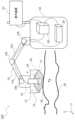
図1には、本発明の実施形態に係るHIFU照射システム100の構成が示されている。HIFU照射システム100は、超音波プローブ10、HIFU振動子ユニット12、カップリング袋14、ロボットアーム18、コントローラ22および表示装置24を備えている。図1では、患者30においてBモード画像等の超音波画像が観測されるべき面(観測対象面)がyz座標平面に平行な面とされ、yz座標平面に垂直な座標軸がx軸とされている。Figure 1 shows the configuration of a
HIFU振動子ユニット12は、開口が下方に向けられた凹面8を有する振動子筐体16と、振動子筐体16における凹面8に沿って配置され、振動子筐体16に固定された複数の超音波振動子36を備えている。HIFU振動子ユニット12は、必ずしも実体的な凹面8を有していなくてもよい。この場合、複数の超音波振動子36は、仮想的な凹面8に沿って配置されるように、振動子筐体16に固定されてよい。The HIFU
振動子筐体16の凹面8は、錐体の側面と同様の形状であってもよい。ここで、錐体とは、空間内の1点から底面に伸びる直線の集合によって形成される立体形状をいう。また、振動子筐体16の凹面8は、上側にドーム状に膨らんだ形状を有してもよい。各超音波振動子36は、各超音波振動子36が超音波を発したときに、振動子筐体16の下方の焦点Fで、超音波の強度が強められるように振動子筐体16に固定されている。The
超音波プローブ10は、振動子筐体16の下方、かつ、焦点Fの上方の位置で超音波が送受信されるように、振動子筐体16に取り付けられている。本実施形態では、振動子筐体16の頂点部を超音波プローブ10が上下方向に貫通し、超音波を送受信するプローブ先端部32が下方に向けられている。超音波プローブ10には方向性があり、超音波プローブ10の構造に応じた方向に面する観測面で、超音波が送受信される。超音波プローブ10は、上下方向に移動自在であってもよい。また、超音波プローブ10は、長手方向の軸を中心に回転自在であってもよい。The
HIFU振動子ユニット12の下方には、各超音波振動子36と患者30との間、および超音波プローブ10と患者30との間の音響インピーダンスを整合させるカップリング袋14が設けられている。カップリング袋14は、水等の液体が充填された袋であってよい。カップリング袋14は、超音波プローブ10と患者30との間に液体を保持する。カップリング袋14は、光を透過する材料で形成されてよく、透明または半透明であってよい。Below the
超音波プローブ10、HIFU振動子ユニット12、およびカップリング袋14は、搬送機構としてのロボットアーム18の先端部に取り付けられている。ロボットアーム18は、関節18bによって接続された複数のアーム18aから構成されており、関節18bを介してコントローラ22の筐体に取り付けられている。各アーム18aが関節18bを回転軸として揺動することで、ロボットアーム18は、超音波プローブ10、HIFU振動子ユニット12およびカップリング袋14を含む可動体20を、x軸、y軸およびz軸の3方向に搬送する。The
コントローラ22は、HIFU制御部26およびロボット制御部28を備えている。HIFU制御部26は、コンピュータ、超音波プローブ10を制御する電気回路、およびHIFU振動子ユニット12を制御する電気回路を備えている。HIFU制御部26が備えるコンピュータは、業務用コンピュータ、パーソナルコンピュータ、タブレットコンピュータ等であってよい。コンピュータはプログラムを実行することで、各画像を生成する処理や、各画像を表示する処理を実行する。HIFU制御部26には、ユーザがHIFU照射システム1を操作するための操作機器(図示せず)が接続されている。操作機器は、マウス、表示装置24と一体化されたタッチパネル、スイッチ、キーボード等を含んでよい。The
HIFU制御部26は、超音波プローブ10およびHIFU振動子ユニット12を動作させるための処理を実行する。例えば、HIFU制御部26は、超音波プローブ10に超音波を送受信させ、超音波プローブ10で受信された超音波に基づく受信信号に基づいて、Bモード画像データを生成し、表示装置24にBモード画像を表示させる。また、HIFU制御部26は、HIFU振動子ユニット12が備える各超音波振動子36に治療用の超音波を送信させる。The HIFU
ロボット制御部28は、HIFU制御部26の制御に応じてロボットアーム18を制御し、ロボットアーム18に可動体20を搬送させてよい。また、ロボット制御部28は操作機器を備えてもよい。この場合、ロボット制御部28は、ユーザによる操作機器の操作に応じてロボットアーム18を制御してもよい。The
治療用の超音波がHIFU振動子ユニット12から患者30に照射される前には、以下のような位置決め処理が実行されてよい。HIFU制御部26は、各超音波振動子36に、治療時よりも強度が小さい超音波を送信させる。超音波プローブ10の位置および姿勢は、超音波プローブ10の観測面が、患者30の観測対象面に一致する位置および姿勢に設定される。HIFU制御部26は、患者30の観測対象面で超音波プローブ10に超音波ビームを走査させBモード画像データを取得する。HIFU制御部26は、Bモード画像を表示装置24に表示させる。施術者としてのユーザは、表示装置24に表示されたBモード画像を参照して、HIFU振動子ユニット12から送信される超音波の焦点Fと患部の位置との相違を確認する。Before the therapeutic ultrasound is irradiated from the
ユーザは、焦点Fの位置と患部の位置との相違が許容範囲内でないときは、ロボットアーム18を動作させて超音波プローブ10およびHIFU振動子ユニット12の位置または姿勢を変更する。ユーザは、焦点Fの位置と患部の位置とが一致していることを確認した後に、HIFU制御部26に対して治療のための操作を行う。HIFU制御部26は、ユーザによる操作に応じて、治療に必要な強度を有する治療用超音波を各超音波振動子36に送信させる。これによって、焦点Fにおいて生体組織が焼灼され、治療が施される。When the difference between the position of the focal point F and the position of the affected area is not within an acceptable range, the user operates the
HIFU照射システム100では、外部から与えられる衝撃や経時変化等によって、超音波振動子36の特性が変化することがある。これによって、焦点Fにおける治療用超音波の強度が低下したりすることがある。そこで、本実施形態に係るHIFU照射システム100では、治療が行われる前に次のような振動子検査が実行される。In the
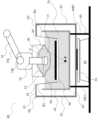
図2には、超音波振動子検査装置38の斜視図が判定装置90と共に示されている。図3には、超音波振動子検査装置38の平面図が示されている。図4には超音波振動子検査装置38の正面図が示され、図5には超音波振動子検査装置38の右側面図が示されている。超音波振動子検査装置38は、重量計40、容器42、容器支持構造60、超音波受信板46および受信板支持構造62を備えている。重量計40には、例えば、電子天秤が用いられる。判定装置90は、HIFU照射システム100が備えるコントローラ22および表示装置24であってもよい。Figure 2 shows a perspective view of the ultrasonic
超音波振動子検査装置38は、容器42に液体を満たし、その液体に超音波受信板46を浸し、HIFU振動子ユニット12から超音波受信板46に超音波を照射するものである。超音波受信板46が超音波から受けた力は、受信板支持構造62を介して、容器42の下方に置かれた重量計40に与えられる。HIFU振動子ユニット12が超音波を送信したときにおける重量計40の測定値に基づいて、重量計40に接続された判定装置90がHIFU振動子ユニット12が備える各超音波振動子36が正常であるか否かを判定する。また、ユーザが重量計40の測定値を読み取り、超音波振動子36が正常であるか否かをユーザが判定してもよい。The ultrasonic
超音波振動子検査装置38の具体的な構成について説明する。容器支持構造60は、左側手前の支柱48L1、左側奥の支柱48L2、右側手前の支柱48R1、右側奥の48R2、左側の梁50Lおよび右側の梁50Rを備えている。以下の説明では、支柱48L1、48L2、48R1および48R2のうちいずれかまたは総てを指す符号として「48」が用いられ、梁50Lおよび50Rのうちいずれかまたは両方を指す符号として「50」が用いられることがある。The specific configuration of the ultrasonic
各支柱48および各梁50は略四角柱形状を有している。左側の梁50Lは、支柱48L1の上端と支柱48L2の上端との間を結合している。右側の梁50Rは、支柱48R1の上端と支柱48R2の上端との間を結合している。各支柱48の下端は土台52に固定されており、支柱48L1および48L2が土台52の上で梁50Lを支持し、支柱48R1および48R2が土台52の上で梁50Rを支持している。梁50Rおよび50Lの上面には、梁50Rと梁50Lとの間を橋渡すように、中空の略直方体形状の容器42が配置され、容器42が2本の梁50Lおよび50Rに支持されている。容器42は上側に開口を有している。Each support 48 and each beam 50 has a generally rectangular prism shape. The
ここでは、2本の梁50Lおよび50Rが容器42を支持する構造が示されているが、2本の梁50Lおよび50Rの代わりに板部材が用いられてよい。この場合、4本の支柱48の上端に板部材が結合し、板部材の上面に容器42が配置される。Here, a structure in which two
容器42の下方では、土台52上に重量計40が配置されている。重量計40は、上面に計量部としての計量皿54を有しており、計量皿54から下方に加えられた力を測定する。重量計40は、測定値を判定装置90に出力する。Below the
受信板支持構造62は、底部64、柱P1~P4、支持棒A1~A4および支持線B1~B4を備えている。図3において破線で示されているように、底部64は、異なる4方向に向かって、水平面内で放射状に延びた帯状の突出部Q1~Q4が、中心板Cで結合された構造を有している。本実施形態では、中心板Cは略矩形に形成され、中心板Cの四隅から同一の長さで突出部Q1~Q4が延びている。中心板Cは、重量計40の計量皿54に支持されている。The receiving
図2に示されているように、突出部Q1~Q4の先端部からは、それぞれ、4本の柱P1~P4が上方に延びている。柱P1およびP2のそれぞれの上端からは右方向に支持棒A1およびA2が延び、柱P3およびP4のそれぞれの上端からは左方向に支持棒A3およびA4が延びている。As shown in FIG. 2, four pillars P1 to P4 extend upward from the tips of protrusions Q1 to Q4, respectively. Support rods A1 and A2 extend to the right from the top ends of pillars P1 and P2, respectively, and support rods A3 and A4 extend to the left from the top ends of pillars P3 and P4, respectively.
超音波受信板46は、略矩形板状に形成されている。超音波受信板46は、複数枚の板部材が重ねられることで形成されてよい。図3~図5に示されているように、本実施形態では、超音波受信板46は、基本板58と2枚の超音波吸収板56から構成されている。2枚の超音波吸収板56は基本板58の上面で重ねられている。HIFU振動子ユニット12から照射された超音波を反射する程度および吸収する程度は、超音波吸収板56の材質や枚数等によって調整されてよい。The
図2~図5に示されているように、支持棒A1の先端部と、超音波受信板46における基本板58の左側手前の角部(角の近傍)との間は支持線B1によって結合され、支持棒A2の先端部と基本板58の左側奥の角部との間は支持線B2によって結合されている。支持棒A3の先端部と基本板58の右側奥の角部との間は支持線B3によって結合され、支持棒A4の先端部と基本板58の左側手前の角部との間は支持線B4によって結合されている。支持部材としての支持線B1~B4は、ピアノ線のような金属線や、樹脂や天然素材で形成された糸であってよい。このように、支持線B1~B4の一端は、それぞれ、支持棒A1~A4に結合し、支持線B1~B4の他端は、超音波受信板46における基本板58の四隅、すなわち4つの角部に結合する。支持線B1~B4は容器42内で超音波受信板46を支持する。2 to 5, the tip of the support rod A1 is connected to the left front corner (near the corner) of the
受信板支持構造62によって、超音波受信板46は、容器42に接触しない状態で容器内で宙吊りにされる。超音波受信板46が容器内で宙吊りにされた状態で容器42には水等の液体が注入され、超音波受信板46が液体に浸される。超音波受信板46に下方に力が加えられると、支持線B1~B4、支持棒A1~A4、柱P1~P4および突出部Q1~Q4を介して、中心板Cから計量皿54に下方に力が加えられる。The receiving
このように、本発明の実施形態に係る超音波振動子検査装置38は、重量計40の計量部としての計量皿54に接触する底部64と、底部64の上方に位置し、上側に開口を有する容器42と、底部64の周辺部から容器42の側方を上側に延びる複数の柱構造と、HIFU振動子ユニット12が備える各超音波振動子36から超音波が照射される超音波受信板46と、複数の柱構造に結合し、超音波受信板46を容器42内で支持する支持部材としての支持線B1~B4とを備えている。柱構造は、4本の柱P1~P4と、柱P1~P4の上端にそれぞれ結合する支持棒A1~A4とを備えている。Thus, the ultrasonic
支持線B1~B4は、それぞれ、柱P1~P4に一端が結合し、他端が超音波受信板46の周辺部に結合する。支持線B1~B4のそれぞれは、剛性の延伸部材、例えば、剛性の棒等に置き換えられてもよい。One end of each of the support wires B1 to B4 is connected to a pillar P1 to P4, and the other end is connected to the periphery of the
底部64は、水平面内で放射状に延びる4つの突出部Q1~Q4を有し、各突出部Q1~Q4の先端部から、それぞれ、柱P1~P4構造が延びている。The bottom 64 has four protrusions Q1 to Q4 that extend radially in a horizontal plane, and pillar structures P1 to P4 extend from the tips of each of the protrusions Q1 to Q4, respectively.
超音波振動子検査装置38は、重量計40が設置された土台52で容器42を支持する容器支持構造60を備えている。The ultrasonic
図6には、容器42に液体70が注入され、超音波受信板46が液体70に浸され、さらに、HIFU振動子ユニット12の下方のカップリング袋14の下方の一部が、超音波受信板46の上方で液体70に浸された状態が模式的に示されている。HIFU振動子ユニット12およびカップリング袋14はHIFU照射システム100に組み込まれた状態であってよい。HIFU振動子ユニット12およびカップリング袋14の位置は、ロボットアーム18の制御によって調整されてよい。HIFU振動子ユニット12における凹面8の開口と超音波受信板46の上面との間の距離は、凹面8の開口と焦点Fとの間の距離のおよそ半分であってよい。6 shows a schematic state in which
このような検査状態で、HIFU制御部26は、操作機器におけるユーザの操作に応じて、HIFU振動子ユニット12の各超音波振動子36に超音波を送信させる。各超音波振動子36が超音波を発することで超音波受信板46に超音波が照射され、超音波受信板46は、超音波から下方に力が与えられる。超音波受信板46に下方に加えられた力は、支持線B1~B4、支持棒A1~A4、柱P1~P4および突出部Q1~Q4を介して中心板Cから重量計40の計量皿54に与えられる。これによって、重量計40が判定装置90に出力する測定値が変化する。In this examination state, the
判定装置90は、測定値に基づいて、HIFU振動子ユニット12が備える各超音波振動子36が正常であるか否かを判定する。判定装置90は、例えば、測定値が所定の閾値Thを超えたときは、HIFU振動子ユニット12が備える各超音波振動子36が正常であると判定する。一方、測定値が閾値Th以下であるときは、HIFU振動子ユニット12が備える複数の超音波振動子36のうちいずれか、または総てが異常であると判定する。The determination device 90 determines whether each
重量計40または判定装置90は重量計40の測定値を表示してよい。この場合、ユーザは、表示された測定値によって、HIFU振動子ユニット12が備える各超音波振動子が正常であるか否かを判定してもよい。The weighing
本発明の実施形態に係る超音波振動子検査装置38では、超音波受信板46の重量と、超音波が超音波受信板46に与えた力は、受信板支持構造62から重量計40に伝えられる。一方、容器42および液体70の重量は、容器支持構造60から土台52に伝わり、重量計40には伝わらない。そのため、容器42および液体70の重量は重量計40の測定値に含まれない。これによって、重量計40の測定値に対する比率に応じた誤差が小さくなり、重量計40の測定値の精度が向上する。したがって、各超音波振動子36から発せられた超音波に基づく測定値が判定装置90によって正確に取得される。また、重量計40または判定装置90が、重量計40の測定値を表示する場合には、ユーザが測定値を正確に読み取ることができる。In the ultrasonic
上記では、受信板支持構造62の底部64として、異なる4方向に向かって放射状に延びた突出部Q1~Q4が、中心板Cで結合されたものが示された。底部64は、異なる3方向に向かって中心板Cから放射状に延びた3つの突出部を有するものであってもよい。また、底部64は、Nを4以上の整数として、異なるN方向に向かって中心板Cから放射状に延びたN個の突出部を有するものであってよい。この場合も、各突出部の先端部から上方に柱が延びる。また、中心板Cは、円、楕円、多角形等の形状を有する板状の部材であってよい。In the above, the bottom 64 of the receiver
[本発明の構成]
構成1:
重量計の計量部に接触する底部と、
前記底部の上方に位置し、上側に開口を有する容器と、
前記底部の周辺部から前記容器の側方を上側に延びる複数の柱構造と、
超音波振動子から超音波が照射される超音波受信板と、
複数の前記柱構造に結合し、前記超音波受信板を前記容器内で支持する支持部材と、
を備えることを特徴とする超音波振動子検査装置。
構成2:
構成1に記載の超音波振動子検査装置であって、
前記支持部材は、
前記柱構造に一端が結合し、他端が前記超音波受信板の周辺部に結合する支持線を備えることを特徴とする超音波振動子検査装置。
構成3:
構成1に記載の超音波振動子検査装置であって、
前記支持部材は、
前記柱構造に一端が結合し、他端が前記超音波受信板の周辺部に結合する剛性の延伸部材を備えることを特徴とする超音波振動子検査装置。
構成4:
構成1から構成3のいずれか1つに記載の超音波振動子検査装置であって、
前記底部は、
水平面内で放射状に延びる複数の突出部を有し、
各前記突出部の先端部から前記柱構造が延びていることを特徴とする超音波振動子検査装置。
構成5:
構成1から構成4のいずれか1つに記載の超音波振動子検査装置であって、
前記容器に収容された液体に浸された前記超音波受信板に向けて、前記超音波振動子が超音波を送信することを特徴とする超音波振動子検査装置。
構成6:
構成1から構成5のいずれか1つに記載の超音波振動子検査装置であって、
前記重量計が設置された土台で前記容器を支持する容器支持構造を備え、
前記重量計は、前記土台に配置されていることを特徴とする超音波振動子検査装置。[Configuration of the present invention]
Configuration 1:
A bottom portion that contacts a weighing portion of a weighing scale;
a container located above the bottom and having an opening on its upper side;
a plurality of post structures extending upwardly and laterally from a periphery of the bottom of the container;
an ultrasonic receiving plate onto which ultrasonic waves are irradiated from an ultrasonic transducer;
a support member coupled to a plurality of said column structures and configured to support said ultrasonic receiving plate within said container;
An ultrasonic transducer inspection device comprising:
Configuration 2:
The ultrasonic transducer inspection device according to configuration 1,
The support member is
an ultrasonic transducer inspection device comprising a support wire having one end connected to the pillar structure and the other end connected to the periphery of the ultrasonic receiving plate;
Configuration 3:
The ultrasonic transducer inspection device according to configuration 1,
The support member is
an ultrasonic transducer inspection device comprising: a rigid extension member having one end connected to the pillar structure and the other end connected to a peripheral portion of the ultrasonic receiving plate;
Configuration 4:
An ultrasonic transducer inspection device according to any one of configurations 1 to 3,
The bottom portion is
A plurality of protrusions extending radially in a horizontal plane;
An ultrasonic transducer inspection device, characterized in that the pillar structure extends from the tip of each of the protrusions.
Configuration 5:
An ultrasonic transducer inspection device according to any one of configurations 1 to 4,
4. An ultrasonic transducer inspection device, comprising: an ultrasonic transducer that transmits ultrasonic waves toward the ultrasonic receiving plate that is immersed in the liquid contained in the container.
Configuration 6:
An ultrasonic transducer inspection device according to any one of configurations 1 to 5,
a container support structure for supporting the container on a base on which the weighing scale is installed;
The ultrasonic transducer inspection device is characterized in that the weight scale is disposed on the base.
8 凹面、10 超音波プローブ、12 HIFU振動子ユニット、14 カップリング袋、16 振動子筐体、18 ロボットアーム、18a アーム、18b 関節、20 可動体、22 コントローラ、24 表示装置、26 HIFU制御部、28 ロボット制御部、30 患者、32 プローブ先端部、36 超音波振動子、38 超音波振動子検査装置、40 重量計、42 容器、46 超音波受信板、48L1,48L2,48R1,48R2 支柱、50L,50R 梁、52 土台、54 計量皿、56 超音波吸収板、58 基本板、60 容器支持構造、62 受信板支持構造、64 底部、100 HIFU照射システム、A1~A4 支持棒、B1~B4 支持線、C 中心板、P1~P4 柱、Q1~Q4 突出部。8 concave surface, 10 ultrasonic probe, 12 HIFU transducer unit, 14 coupling bag, 16 transducer housing, 18 robot arm, 18a arm, 18b joint, 20 movable body, 22 controller, 24 display device, 26 HIFU control unit, 28 robot control unit, 30 patient, 32 probe tip, 36 ultrasonic transducer, 38 ultrasonic transducer inspection device, 40 weighing scale, 42 container, 46 ultrasonic receiving plate, 48L1, 48L2, 48R1, 48R2 support, 50L, 50R beam, 52 base, 54 weighing dish, 56 ultrasonic absorbing plate, 58 base plate, 60 container support structure, 62 receiving plate support structure, 64 bottom, 100 HIFU irradiation system, A1 to A4 support rod, B1 to B4 support wire, C Center plate, P1 to P4 pillars, Q1 to Q4 protrusions.
Claims (6)
Translated fromJapanese前記底部の上方に位置し、上側に開口を有する容器と、
前記底部の周辺部から前記容器の側方を上側に延びる複数の柱構造と、
超音波振動子から超音波が照射される超音波受信板と、
複数の前記柱構造に結合し、前記超音波受信板を前記容器内で支持する支持部材と、
を備えることを特徴とする超音波振動子検査装置。 A bottom portion that contacts a weighing portion of a weighing scale;
a container located above the bottom and having an opening on its upper side;
a plurality of post structures extending upwardly and laterally from a periphery of the bottom of the container;
an ultrasonic receiving plate onto which ultrasonic waves are irradiated from an ultrasonic transducer;
a support member coupled to a plurality of said column structures and configured to support said ultrasonic receiving plate within said container;
An ultrasonic transducer inspection device comprising:
前記支持部材は、
前記柱構造に一端が結合し、他端が前記超音波受信板の周辺部に結合する支持線を備えることを特徴とする超音波振動子検査装置。 2. The ultrasonic transducer inspection device according to claim 1,
The support member is
an ultrasonic transducer inspection device comprising a support wire having one end connected to the pillar structure and the other end connected to the periphery of the ultrasonic receiving plate;
前記支持部材は、
前記柱構造に一端が結合し、他端が前記超音波受信板の周辺部に結合する剛性の延伸部材を備えることを特徴とする超音波振動子検査装置。 2. The ultrasonic transducer inspection device according to claim 1,
The support member is
an ultrasonic transducer inspection device comprising: a rigid extension member having one end connected to the pillar structure and the other end connected to a periphery of the ultrasonic receiving plate;
前記底部は、
水平面内で放射状に延びる複数の突出部を有し、
各前記突出部の先端部から前記柱構造が延びていることを特徴とする超音波振動子検査装置。 The ultrasonic transducer inspection device according to any one of claims 1 to 3,
The bottom portion is
A plurality of protrusions extending radially in a horizontal plane;
An ultrasonic transducer inspection device, characterized in that the pillar structure extends from the tip of each of the protrusions.
前記容器に収容された液体に浸された前記超音波受信板に向けて、前記超音波振動子が超音波を送信することを特徴とする超音波振動子検査装置。 The ultrasonic transducer inspection device according to any one of claims 1 to 3,
4. An ultrasonic transducer inspection device, comprising: an ultrasonic transducer that transmits ultrasonic waves toward the ultrasonic receiving plate that is immersed in the liquid contained in the container.
前記重量計が設置された土台で前記容器を支持する容器支持構造を備え、
前記重量計は、前記土台に配置されていることを特徴とする超音波振動子検査装置。 The ultrasonic transducer inspection device according to any one of claims 1 to 3,
a container support structure for supporting the container on a base on which the weighing scale is installed;
The ultrasonic transducer inspection device is characterized in that the weight scale is disposed on the base.
Priority Applications (1)
| Application Number | Priority Date | Filing Date | Title |
|---|---|---|---|
| JP2023179239AJP7611607B1 (en) | 2023-10-18 | 2023-10-18 | Ultrasonic transducer inspection device |
Applications Claiming Priority (1)
| Application Number | Priority Date | Filing Date | Title |
|---|---|---|---|
| JP2023179239AJP7611607B1 (en) | 2023-10-18 | 2023-10-18 | Ultrasonic transducer inspection device |
Publications (2)
| Publication Number | Publication Date |
|---|---|
| JP7611607B1true JP7611607B1 (en) | 2025-01-10 |
| JP2025069497A JP2025069497A (en) | 2025-05-01 |
Family
ID=94169166
Family Applications (1)
| Application Number | Title | Priority Date | Filing Date |
|---|---|---|---|
| JP2023179239AActiveJP7611607B1 (en) | 2023-10-18 | 2023-10-18 | Ultrasonic transducer inspection device |
Country Status (1)
| Country | Link |
|---|---|
| JP (1) | JP7611607B1 (en) |
Citations (4)
| Publication number | Priority date | Publication date | Assignee | Title |
|---|---|---|---|---|
| US20030105398A1 (en) | 2001-12-03 | 2003-06-05 | Insightec-Txsonics Ltd. | Apparatus, systems, and methods for measuring power output of an ultrasound transducer |
| JP2013520660A (en) | 2010-02-26 | 2013-06-06 | ナンジン ハイカ メディカル イクウィップメント カンパニー リミテッド | High density focused ultrasonic measurement absorption target |
| US20130197350A1 (en) | 2010-10-04 | 2013-08-01 | Koninklijke Philips Electronics N.V. | Radiation force balance calibrator |
| JP2018534013A (en) | 2015-09-22 | 2018-11-22 | ジョンソン・アンド・ジョンソン・コンシューマー・インコーポレイテッドJohnson & Johnson Consumer Inc. | Apparatus and method for enhancing topical application of benefit agent |
- 2023
- 2023-10-18JPJP2023179239Apatent/JP7611607B1/enactiveActive
Patent Citations (4)
| Publication number | Priority date | Publication date | Assignee | Title |
|---|---|---|---|---|
| US20030105398A1 (en) | 2001-12-03 | 2003-06-05 | Insightec-Txsonics Ltd. | Apparatus, systems, and methods for measuring power output of an ultrasound transducer |
| JP2013520660A (en) | 2010-02-26 | 2013-06-06 | ナンジン ハイカ メディカル イクウィップメント カンパニー リミテッド | High density focused ultrasonic measurement absorption target |
| US20130197350A1 (en) | 2010-10-04 | 2013-08-01 | Koninklijke Philips Electronics N.V. | Radiation force balance calibrator |
| JP2018534013A (en) | 2015-09-22 | 2018-11-22 | ジョンソン・アンド・ジョンソン・コンシューマー・インコーポレイテッドJohnson & Johnson Consumer Inc. | Apparatus and method for enhancing topical application of benefit agent |
Also Published As
| Publication number | Publication date |
|---|---|
| JP2025069497A (en) | 2025-05-01 |
Similar Documents
| Publication | Publication Date | Title |
|---|---|---|
| JPS5930423B2 (en) | Ultrasonic inspection device | |
| KR20160012590A (en) | Ultrasound imaging apparatus and controlling method thereof | |
| JP2006305361A5 (en) | ||
| KR101767446B1 (en) | performance measuring system for ultrasonic transducers | |
| US20130261449A1 (en) | Ultrasound diagnostic apparatus | |
| JP7195218B2 (en) | Radiation imaging system, medical imaging system, control method, and control program | |
| KR20150041723A (en) | Ultrasonic probe and medical apparatus including the same | |
| JP7611607B1 (en) | Ultrasonic transducer inspection device | |
| JP5609960B2 (en) | Ultrasonic diagnostic equipment | |
| EP4442206A1 (en) | Ultrasonic therapeutic device | |
| KR20150020945A (en) | Acoustic probe and Method for manufacturing the same | |
| KR20170093338A (en) | Ultrasound diagnostic apparatus and control method for the same | |
| JP2012235850A (en) | Ultrasonic diagnostic apparatus | |
| JP7737184B2 (en) | Ultrasonic scanner and method for correcting ultrasonic signals in said ultrasonic scanner | |
| JP7122483B1 (en) | Ultrasonic Imaging Probe and Ultrasonic Image Display Device for HIFU Irradiation Device | |
| JP7716133B1 (en) | Acoustic coupler for HIFU treatment | |
| JP7681337B2 (en) | Ultrasonic therapy device | |
| CN113362691B (en) | A practical training system for fetal heart ultrasound examination based on intelligent control | |
| JP7503342B1 (en) | HIFU irradiation device and method for evaluating its condition | |
| JP7082441B1 (en) | Ultrasonic oscillator inspection device and inspection method | |
| JP2021000275A (en) | Medical image photographing system | |
| JP7301426B1 (en) | HIFU irradiation equipment | |
| CN118415678B (en) | Ultrasonic Doppler diagnostic instrument performance test system | |
| JP7354009B2 (en) | Ultrasound diagnostic equipment | |
| EP4591926A1 (en) | Hifu irradiation device and focus adjustment method |
Legal Events
| Date | Code | Title | Description |
|---|---|---|---|
| A621 | Written request for application examination | Free format text:JAPANESE INTERMEDIATE CODE: A621 Effective date:20241015 | |
| A871 | Explanation of circumstances concerning accelerated examination | Free format text:JAPANESE INTERMEDIATE CODE: A871 Effective date:20241015 | |
| A521 | Request for written amendment filed | Free format text:JAPANESE INTERMEDIATE CODE: A523 Effective date:20241029 | |
| TRDD | Decision of grant or rejection written | ||
| A01 | Written decision to grant a patent or to grant a registration (utility model) | Free format text:JAPANESE INTERMEDIATE CODE: A01 Effective date:20241210 | |
| A61 | First payment of annual fees (during grant procedure) | Free format text:JAPANESE INTERMEDIATE CODE: A61 Effective date:20241217 | |
| R150 | Certificate of patent or registration of utility model | Ref document number:7611607 Country of ref document:JP Free format text:JAPANESE INTERMEDIATE CODE: R150 |