JP7609364B2 - Intravascular device with radiopaque body markers - Patents.com - Google Patents
Intravascular device with radiopaque body markers - Patents.comDownload PDFInfo
- Publication number
- JP7609364B2 JP7609364B2JP2020102120AJP2020102120AJP7609364B2JP 7609364 B2JP7609364 B2JP 7609364B2JP 2020102120 AJP2020102120 AJP 2020102120AJP 2020102120 AJP2020102120 AJP 2020102120AJP 7609364 B2JP7609364 B2JP 7609364B2
- Authority
- JP
- Japan
- Prior art keywords
- struts
- circumference
- bent
- capture device
- strut
- Prior art date
- Legal status (The legal status is an assumption and is not a legal conclusion. Google has not performed a legal analysis and makes no representation as to the accuracy of the status listed.)
- Active
Links
Images


Classifications
- A—HUMAN NECESSITIES
- A61—MEDICAL OR VETERINARY SCIENCE; HYGIENE
- A61B—DIAGNOSIS; SURGERY; IDENTIFICATION
- A61B90/00—Instruments, implements or accessories specially adapted for surgery or diagnosis and not covered by any of the groups A61B1/00 - A61B50/00, e.g. for luxation treatment or for protecting wound edges
- A61B90/39—Markers, e.g. radio-opaque or breast lesions markers
- A—HUMAN NECESSITIES
- A61—MEDICAL OR VETERINARY SCIENCE; HYGIENE
- A61F—FILTERS IMPLANTABLE INTO BLOOD VESSELS; PROSTHESES; DEVICES PROVIDING PATENCY TO, OR PREVENTING COLLAPSING OF, TUBULAR STRUCTURES OF THE BODY, e.g. STENTS; ORTHOPAEDIC, NURSING OR CONTRACEPTIVE DEVICES; FOMENTATION; TREATMENT OR PROTECTION OF EYES OR EARS; BANDAGES, DRESSINGS OR ABSORBENT PADS; FIRST-AID KITS
- A61F2/00—Filters implantable into blood vessels; Prostheses, i.e. artificial substitutes or replacements for parts of the body; Appliances for connecting them with the body; Devices providing patency to, or preventing collapsing of, tubular structures of the body, e.g. stents
- A61F2/82—Devices providing patency to, or preventing collapsing of, tubular structures of the body, e.g. stents
- A—HUMAN NECESSITIES
- A61—MEDICAL OR VETERINARY SCIENCE; HYGIENE
- A61B—DIAGNOSIS; SURGERY; IDENTIFICATION
- A61B17/00—Surgical instruments, devices or methods
- A61B17/22—Implements for squeezing-off ulcers or the like on inner organs of the body; Implements for scraping-out cavities of body organs, e.g. bones; for invasive removal or destruction of calculus using mechanical vibrations; for removing obstructions in blood vessels, not otherwise provided for
- A61B17/221—Gripping devices in the form of loops or baskets for gripping calculi or similar types of obstructions
- A—HUMAN NECESSITIES
- A61—MEDICAL OR VETERINARY SCIENCE; HYGIENE
- A61B—DIAGNOSIS; SURGERY; IDENTIFICATION
- A61B8/00—Diagnosis using ultrasonic, sonic or infrasonic waves
- A61B8/12—Diagnosis using ultrasonic, sonic or infrasonic waves in body cavities or body tracts, e.g. by using catheters
- A—HUMAN NECESSITIES
- A61—MEDICAL OR VETERINARY SCIENCE; HYGIENE
- A61F—FILTERS IMPLANTABLE INTO BLOOD VESSELS; PROSTHESES; DEVICES PROVIDING PATENCY TO, OR PREVENTING COLLAPSING OF, TUBULAR STRUCTURES OF THE BODY, e.g. STENTS; ORTHOPAEDIC, NURSING OR CONTRACEPTIVE DEVICES; FOMENTATION; TREATMENT OR PROTECTION OF EYES OR EARS; BANDAGES, DRESSINGS OR ABSORBENT PADS; FIRST-AID KITS
- A61F2/00—Filters implantable into blood vessels; Prostheses, i.e. artificial substitutes or replacements for parts of the body; Appliances for connecting them with the body; Devices providing patency to, or preventing collapsing of, tubular structures of the body, e.g. stents
- A61F2/82—Devices providing patency to, or preventing collapsing of, tubular structures of the body, e.g. stents
- A61F2/86—Stents in a form characterised by the wire-like elements; Stents in the form characterised by a net-like or mesh-like structure
- A61F2/89—Stents in a form characterised by the wire-like elements; Stents in the form characterised by a net-like or mesh-like structure the wire-like elements comprising two or more adjacent rings flexibly connected by separate members
- A—HUMAN NECESSITIES
- A61—MEDICAL OR VETERINARY SCIENCE; HYGIENE
- A61F—FILTERS IMPLANTABLE INTO BLOOD VESSELS; PROSTHESES; DEVICES PROVIDING PATENCY TO, OR PREVENTING COLLAPSING OF, TUBULAR STRUCTURES OF THE BODY, e.g. STENTS; ORTHOPAEDIC, NURSING OR CONTRACEPTIVE DEVICES; FOMENTATION; TREATMENT OR PROTECTION OF EYES OR EARS; BANDAGES, DRESSINGS OR ABSORBENT PADS; FIRST-AID KITS
- A61F2/00—Filters implantable into blood vessels; Prostheses, i.e. artificial substitutes or replacements for parts of the body; Appliances for connecting them with the body; Devices providing patency to, or preventing collapsing of, tubular structures of the body, e.g. stents
- A61F2/95—Instruments specially adapted for placement or removal of stents or stent-grafts
- A—HUMAN NECESSITIES
- A61—MEDICAL OR VETERINARY SCIENCE; HYGIENE
- A61M—DEVICES FOR INTRODUCING MEDIA INTO, OR ONTO, THE BODY; DEVICES FOR TRANSDUCING BODY MEDIA OR FOR TAKING MEDIA FROM THE BODY; DEVICES FOR PRODUCING OR ENDING SLEEP OR STUPOR
- A61M25/00—Catheters; Hollow probes
- A61M25/01—Introducing, guiding, advancing, emplacing or holding catheters
- A61M25/0105—Steering means as part of the catheter or advancing means; Markers for positioning
- A61M25/0108—Steering means as part of the catheter or advancing means; Markers for positioning using radio-opaque or ultrasound markers
- A—HUMAN NECESSITIES
- A61—MEDICAL OR VETERINARY SCIENCE; HYGIENE
- A61B—DIAGNOSIS; SURGERY; IDENTIFICATION
- A61B17/00—Surgical instruments, devices or methods
- A61B2017/00831—Material properties
- A—HUMAN NECESSITIES
- A61—MEDICAL OR VETERINARY SCIENCE; HYGIENE
- A61B—DIAGNOSIS; SURGERY; IDENTIFICATION
- A61B17/00—Surgical instruments, devices or methods
- A61B17/22—Implements for squeezing-off ulcers or the like on inner organs of the body; Implements for scraping-out cavities of body organs, e.g. bones; for invasive removal or destruction of calculus using mechanical vibrations; for removing obstructions in blood vessels, not otherwise provided for
- A61B2017/22038—Implements for squeezing-off ulcers or the like on inner organs of the body; Implements for scraping-out cavities of body organs, e.g. bones; for invasive removal or destruction of calculus using mechanical vibrations; for removing obstructions in blood vessels, not otherwise provided for with a guide wire
- A61B2017/22041—Implements for squeezing-off ulcers or the like on inner organs of the body; Implements for scraping-out cavities of body organs, e.g. bones; for invasive removal or destruction of calculus using mechanical vibrations; for removing obstructions in blood vessels, not otherwise provided for with a guide wire outside the catheter
- A—HUMAN NECESSITIES
- A61—MEDICAL OR VETERINARY SCIENCE; HYGIENE
- A61B—DIAGNOSIS; SURGERY; IDENTIFICATION
- A61B17/00—Surgical instruments, devices or methods
- A61B17/22—Implements for squeezing-off ulcers or the like on inner organs of the body; Implements for scraping-out cavities of body organs, e.g. bones; for invasive removal or destruction of calculus using mechanical vibrations; for removing obstructions in blood vessels, not otherwise provided for
- A61B17/221—Gripping devices in the form of loops or baskets for gripping calculi or similar types of obstructions
- A61B2017/2212—Gripping devices in the form of loops or baskets for gripping calculi or similar types of obstructions having a closed distal end, e.g. a loop
- A—HUMAN NECESSITIES
- A61—MEDICAL OR VETERINARY SCIENCE; HYGIENE
- A61B—DIAGNOSIS; SURGERY; IDENTIFICATION
- A61B17/00—Surgical instruments, devices or methods
- A61B17/22—Implements for squeezing-off ulcers or the like on inner organs of the body; Implements for scraping-out cavities of body organs, e.g. bones; for invasive removal or destruction of calculus using mechanical vibrations; for removing obstructions in blood vessels, not otherwise provided for
- A61B17/221—Gripping devices in the form of loops or baskets for gripping calculi or similar types of obstructions
- A61B2017/2215—Gripping devices in the form of loops or baskets for gripping calculi or similar types of obstructions having an open distal end
- A—HUMAN NECESSITIES
- A61—MEDICAL OR VETERINARY SCIENCE; HYGIENE
- A61B—DIAGNOSIS; SURGERY; IDENTIFICATION
- A61B90/00—Instruments, implements or accessories specially adapted for surgery or diagnosis and not covered by any of the groups A61B1/00 - A61B50/00, e.g. for luxation treatment or for protecting wound edges
- A61B90/39—Markers, e.g. radio-opaque or breast lesions markers
- A61B2090/3966—Radiopaque markers visible in an X-ray image
- A—HUMAN NECESSITIES
- A61—MEDICAL OR VETERINARY SCIENCE; HYGIENE
- A61F—FILTERS IMPLANTABLE INTO BLOOD VESSELS; PROSTHESES; DEVICES PROVIDING PATENCY TO, OR PREVENTING COLLAPSING OF, TUBULAR STRUCTURES OF THE BODY, e.g. STENTS; ORTHOPAEDIC, NURSING OR CONTRACEPTIVE DEVICES; FOMENTATION; TREATMENT OR PROTECTION OF EYES OR EARS; BANDAGES, DRESSINGS OR ABSORBENT PADS; FIRST-AID KITS
- A61F2/00—Filters implantable into blood vessels; Prostheses, i.e. artificial substitutes or replacements for parts of the body; Appliances for connecting them with the body; Devices providing patency to, or preventing collapsing of, tubular structures of the body, e.g. stents
- A61F2/82—Devices providing patency to, or preventing collapsing of, tubular structures of the body, e.g. stents
- A61F2002/826—Devices providing patency to, or preventing collapsing of, tubular structures of the body, e.g. stents more than one stent being applied sequentially
- A—HUMAN NECESSITIES
- A61—MEDICAL OR VETERINARY SCIENCE; HYGIENE
- A61F—FILTERS IMPLANTABLE INTO BLOOD VESSELS; PROSTHESES; DEVICES PROVIDING PATENCY TO, OR PREVENTING COLLAPSING OF, TUBULAR STRUCTURES OF THE BODY, e.g. STENTS; ORTHOPAEDIC, NURSING OR CONTRACEPTIVE DEVICES; FOMENTATION; TREATMENT OR PROTECTION OF EYES OR EARS; BANDAGES, DRESSINGS OR ABSORBENT PADS; FIRST-AID KITS
- A61F2220/00—Fixations or connections for prostheses classified in groups A61F2/00 - A61F2/26 or A61F2/82 or A61F9/00 or A61F11/00 or subgroups thereof
- A61F2220/0025—Connections or couplings between prosthetic parts, e.g. between modular parts; Connecting elements
- A61F2220/0075—Connections or couplings between prosthetic parts, e.g. between modular parts; Connecting elements sutured, ligatured or stitched, retained or tied with a rope, string, thread, wire or cable
- A—HUMAN NECESSITIES
- A61—MEDICAL OR VETERINARY SCIENCE; HYGIENE
- A61F—FILTERS IMPLANTABLE INTO BLOOD VESSELS; PROSTHESES; DEVICES PROVIDING PATENCY TO, OR PREVENTING COLLAPSING OF, TUBULAR STRUCTURES OF THE BODY, e.g. STENTS; ORTHOPAEDIC, NURSING OR CONTRACEPTIVE DEVICES; FOMENTATION; TREATMENT OR PROTECTION OF EYES OR EARS; BANDAGES, DRESSINGS OR ABSORBENT PADS; FIRST-AID KITS
- A61F2250/00—Special features of prostheses classified in groups A61F2/00 - A61F2/26 or A61F2/82 or A61F9/00 or A61F11/00 or subgroups thereof
- A61F2250/0014—Special features of prostheses classified in groups A61F2/00 - A61F2/26 or A61F2/82 or A61F9/00 or A61F11/00 or subgroups thereof having different values of a given property or geometrical feature, e.g. mechanical property or material property, at different locations within the same prosthesis
- A61F2250/0039—Special features of prostheses classified in groups A61F2/00 - A61F2/26 or A61F2/82 or A61F9/00 or A61F11/00 or subgroups thereof having different values of a given property or geometrical feature, e.g. mechanical property or material property, at different locations within the same prosthesis differing in diameter
- A—HUMAN NECESSITIES
- A61—MEDICAL OR VETERINARY SCIENCE; HYGIENE
- A61F—FILTERS IMPLANTABLE INTO BLOOD VESSELS; PROSTHESES; DEVICES PROVIDING PATENCY TO, OR PREVENTING COLLAPSING OF, TUBULAR STRUCTURES OF THE BODY, e.g. STENTS; ORTHOPAEDIC, NURSING OR CONTRACEPTIVE DEVICES; FOMENTATION; TREATMENT OR PROTECTION OF EYES OR EARS; BANDAGES, DRESSINGS OR ABSORBENT PADS; FIRST-AID KITS
- A61F2250/00—Special features of prostheses classified in groups A61F2/00 - A61F2/26 or A61F2/82 or A61F9/00 or A61F11/00 or subgroups thereof
- A61F2250/0058—Additional features; Implant or prostheses properties not otherwise provided for
- A61F2250/0096—Markers and sensors for detecting a position or changes of a position of an implant, e.g. RF sensors, ultrasound markers
- A61F2250/0098—Markers and sensors for detecting a position or changes of a position of an implant, e.g. RF sensors, ultrasound markers radio-opaque, e.g. radio-opaque markers
Landscapes
- Health & Medical Sciences (AREA)
- Life Sciences & Earth Sciences (AREA)
- Biomedical Technology (AREA)
- Engineering & Computer Science (AREA)
- Veterinary Medicine (AREA)
- Heart & Thoracic Surgery (AREA)
- Animal Behavior & Ethology (AREA)
- General Health & Medical Sciences (AREA)
- Public Health (AREA)
- Surgery (AREA)
- Vascular Medicine (AREA)
- Oral & Maxillofacial Surgery (AREA)
- Nuclear Medicine, Radiotherapy & Molecular Imaging (AREA)
- Medical Informatics (AREA)
- Molecular Biology (AREA)
- Cardiology (AREA)
- Transplantation (AREA)
- Orthopedic Medicine & Surgery (AREA)
- Pathology (AREA)
- Biophysics (AREA)
- Physics & Mathematics (AREA)
- Radiology & Medical Imaging (AREA)
- Pulmonology (AREA)
- Anesthesiology (AREA)
- Hematology (AREA)
- Surgical Instruments (AREA)
- Media Introduction/Drainage Providing Device (AREA)
- Prostheses (AREA)
Description
Translated fromJapanese本発明は、全般的には血管内治療処置装置に関し、より具体的には、放射線不透過性身体マーカーを有する拡張可能なステント及び血塊回収器に関する。The present invention relates generally to endovascular treatment devices and, more specifically, to an expandable stent and clot retriever having radiopaque body markers.
ステント及び血塊回収器などの血管内装置には、様々な形状、サイズ、及び構成がある。ステント及び血塊回収器の設計における考慮事項には、治療の目標、治療部位の位置、及び治療部位の幾何学的形状が挙げられる。ステント又は血塊回収器は、治療部位に到達するように血管を通り抜けるために、また血塊回収器の場合には、血塊がある血管を通って無傷で後退するために一定程度の可撓性を必要とする場合がある。ステントは、体腔又は塞栓インプラントを支持するためにある程度の構造的一体性を必要とする場合があり、血塊回収器は、血塊の周囲で又は血塊を通って拡張するために一定程度の構造的一体性を必要とする場合がある。ステント又は血塊回収器は、湾曲した脈管構造内で適切に拡張するために一定程度の順応性を必要とする場合がある。最後に、医師が血管内装置を適切に位置付けることができるように、一定程度の放射線不透過性もまた必要とされる場合がある。Intravascular devices such as stents and clot retrievers come in a variety of shapes, sizes, and configurations. Design considerations for stents and clot retrievers include the goal of treatment, the location of the treatment site, and the geometry of the treatment site. A stent or clot retriever may require a degree of flexibility to navigate the vessel to reach the treatment site, and in the case of a clot retriever, to retreat intact through the vessel in which the clot is located. A stent may require a degree of structural integrity to support the body cavity or embolic implant, and a clot retriever may require a degree of structural integrity to expand around or through the clot. A stent or clot retriever may require a degree of conformability to properly expand within the curved vasculature. Finally, a degree of radiopacity may also be required to allow the physician to properly position the endovascular device.
可撓性、構造的一体性、順応性、及び放射線不透過性は、多くの場合、設計目標と競合している。残念ながら、多くの用途では、放射線不透過性材料は、可撓性、構造的一体性、及び順応性の設計目標を満たすための最適な材料特性を有さず、ニチノール及び他の形状記憶金属などの目標に寄与する材料から作製された装置は、放射線不透過性が乏しい場合があり、医師が治療中に装置の位置付けを可視化することは困難である。競合する目標を満たすために、一般に、装置は、可撓性、構造的一体性、及び順応性を達成するようにニチノールなどの材料で主に構成され、放射線不透過性材料が追加される。しかしながら、放射線不透過性材料を血管内装置の本体に組み込むことは困難であり、特に、極度の可撓性、構造的一体性、順応性、又は小さいサイズに合わせて設計された装置において困難である。Flexibility, structural integrity, conformability, and radiopacity are often competing design goals. Unfortunately, in many applications, radiopaque materials do not have optimal material properties to meet the design goals of flexibility, structural integrity, and conformability, and devices made from materials that contribute to these goals, such as Nitinol and other shape memory metals, may have poor radiopacity, making it difficult for physicians to visualize the device positioning during treatment. To meet the competing goals, devices are typically constructed primarily of materials such as Nitinol to achieve flexibility, structural integrity, and conformability, and radiopaque materials are added. However, incorporating radiopaque materials into the body of an intravascular device is difficult, especially in devices designed for extreme flexibility, structural integrity, conformability, or small size.
したがって、放射線不透過性マーカーを有する、改善された又は代替的な血管内装置が必要とされている。Therefore, there is a need for improved or alternative intravascular devices having radiopaque markers.
上述の必要性を満たすシステム、装置、及び方法を提供することが、本発明の目的である。一般に、本発明の目的は、フレームの長さにわたって変化する円周を有するフレームを形成する、円形ストラットと、直線状ストラットと、屈曲ストラットと、から構成された拡張可能なフレームを有する血管内処置装置を提供することである。放射線不透過性マーカーは、フレームの長さに沿ってフレームの外周を示すために、屈曲ストラット上に位置付けられてもよい。装置は、ステント又は血塊回収器であってもよい。装置が血塊回収器である場合、拡張可能なフレームの近位端部は、ガイドワイヤに取り付けてもよく、拡張可能なフレームの遠位端部は、フレームが畳み込み状態から拡張状態へ移動するとき、また逆の場合も同様に、ガイドワイヤにわたって自由に摺動してもよい。It is an object of the present invention to provide a system, device, and method that meets the above-mentioned needs. In general, it is an object of the present invention to provide an endovascular treatment device having an expandable frame composed of circular, straight, and bent struts that form a frame having a circumference that varies over the length of the frame. Radiopaque markers may be positioned on the bent struts to indicate the circumference of the frame along the length of the frame. The device may be a stent or a clot retriever. If the device is a clot retriever, the proximal end of the expandable frame may be attached to a guidewire and the distal end of the expandable frame may slide freely over the guidewire as the frame moves from a collapsed state to an expanded state, and vice versa.
例示的な血管内処置装置は、細長いガイドと、畳み込み構成から拡張構成へ移動することができる拡張可能なフレームワークと、を含んでもよい。畳み込み構成において、フレームワークは、カテーテルの内腔を通って横断するように寸法決めされてもよく、拡張構成において、フレームワークは、血管の内腔内で径方向に延びるように寸法決めされてもよい。An exemplary endovascular treatment device may include an elongate guide and an expandable framework that may be moved from a collapsed configuration to an expanded configuration. In the collapsed configuration, the framework may be dimensioned to traverse through a lumen of the catheter, and in the expanded configuration, the framework may be dimensioned to extend radially within the lumen of the blood vessel.
拡張可能なフレームワークは、環状ストラットと、中央ストラットと、屈曲ストラットと、から構築されてもよい。環状ストラットはそれぞれ、それぞれの環状ストラットが近位方向で隣接する環状ストラットと、遠位方向で隣接する別の環状ストラットと、を有するように、細長いガイドを取り囲むように位置付けられてもよいが、ただし、それぞれが隣接する環状ストラットを1つのみ有する、最遠位の環状ストラット及び最近位の環状ストラットを除く。中央ストラットは、それぞれの環状ストラットを隣接する1つの環状ストラットに接合するように位置付けられてもよく、屈曲ストラットは、それぞれの環状ストラットをその対向する隣接環状ストラットに接合するように位置付けられてもよい。拡張可能なフレームワークが畳み込み構成にあるとき、環状ストラットはそれぞれ、細長いガイドを中心とする収縮位置にあってもよく、屈曲ストラットはそれぞれ、長手方向に細長い形状であってもよい。拡張可能なフレームワークが畳み込み構成から拡張構成へ移動するとき、環状ストラットはそれぞれ、細長いガイドを中心とする径方向の拡張位置へ移動してもよく、中央ストラットは、拡張可能なフレームワークが畳み込み構成にあるときと本質的に同じ形状を維持してもよく、屈曲ストラットはそれぞれ、径方向に拡張された形状へ移動してもよい。The expandable framework may be constructed from annular struts, a central strut, and bent struts. Each of the annular struts may be positioned to surround the elongated guide such that each annular strut has a proximally adjacent annular strut and another distally adjacent annular strut, except for the most distal and most proximal annular struts, each of which has only one adjacent annular strut. The central strut may be positioned to join each annular strut to one adjacent annular strut, and the bent struts may be positioned to join each annular strut to its opposing adjacent annular strut. When the expandable framework is in a collapsed configuration, each of the annular struts may be in a contracted position about the elongated guide, and each of the bent struts may be longitudinally elongated. When the expandable framework moves from the collapsed configuration to the expanded configuration, each of the annular struts may move to a radially expanded position about the elongate guide, the central strut may maintain essentially the same shape as when the expandable framework is in the collapsed configuration, and each of the bent struts may move to a radially expanded shape.
拡張可能なフレームワークが拡張構成にあるとき、屈曲ストラットの群は、拡張可能なフレームワークの外周を画定するように位置付けられてもよい。屈曲ストラットの群によって画定される円周は、屈曲ストラットのうちの1つの群が、屈曲ストラットの異なる群によって画定される別の円周よりも小さい円周を画定することができるように、屈曲ストラットの1つの群ごとに異なってもよい。拡張可能なフレームは、フレームの遠位端部付近の遠位群と、フレームの近位端部付近の近位群と、近位群と遠位群との間の1つ以上の中間群と、を含む、いくつかの群の屈曲ストラットを含んでもよい。遠位群及び近位群はそれぞれ、屈曲ストラットの中間群によって画定されるいかなる円周よりもそれぞれ大きい円周を画定してもよい。あるいは、屈曲ストラットの群のそれぞれは、屈曲ストラットの他の群のそれぞれによって画定される円周に実質的に等しい円周を画定してもよい。When the expandable framework is in the expanded configuration, the groups of bent struts may be positioned to define a circumference of the expandable framework. The circumference defined by the groups of bent struts may vary from one group of bent struts to another group of bent struts such that one group of bent struts may define a smaller circumference than another circumference defined by a different group of bent struts. The expandable frame may include several groups of bent struts, including a distal group near a distal end of the frame, a proximal group near a proximal end of the frame, and one or more intermediate groups between the proximal and distal groups. The distal and proximal groups may each define a circumference greater than any circumference defined by the intermediate groups of bent struts. Alternatively, each of the groups of bent struts may define a circumference substantially equal to the circumference defined by each of the other groups of bent struts.
拡張可能なフレームワークが拡張構成にあるとき、中央ストラットの群は、拡張可能なフレームワークの内周をそれぞれ画定するように位置付けられてもよい。中央ストラットの群のうちの少なくとも1つによって画定される円周のうちの少なくとも1つは、屈曲ストラットの群のうちの少なくとも1つによって画定される円周のうちの少なくとも1つよりも小さくてもよい。より小さい円周を有する中央ストラットの群は、拡張可能なフレームワークが、その長さの一部又は全部に沿って、屈曲ストラットによって画定されるより大きい円周と、中央ストラットによって画定されるより小さい円周との間で移行する可変円周を有するように、より大きい円周を有する屈曲ストラットの群の間に位置付けられてもよい。When the expandable framework is in the expanded configuration, the groups of central struts may be positioned to each define an inner circumference of the expandable framework. At least one of the circumferences defined by at least one of the groups of central struts may be smaller than at least one of the circumferences defined by at least one of the groups of bent struts. The groups of central struts having smaller circumferences may be positioned between the groups of bent struts having larger circumferences such that the expandable framework has a variable circumference along some or all of its length that transitions between the larger circumference defined by the bent struts and the smaller circumference defined by the central struts.
拡張可能なフレームワークが拡張構成にあるとき、拡張可能な本体は、第1の群の屈曲ストラットによって画定される第1の円周と、第1の群の屈曲ストラットに隣接して位置付けられた第1の群の中央ストラットによって画定される第2の円周と、有してもよい。第2の円周は、第1の円周よりも小さい寸法であってもよい。第2の群の屈曲ストラットは、第3の円周を画定するように、第1の群の中央ストラットに隣接して位置付けられてもよい。第2の群の中央ストラットは、第4の円周を画定するように、第2の群の屈曲ストラットに隣接して位置付けられてもよい。第4の円周は、第2の円周にほぼ等しくてもよい。第1の円周は、第2の円周の約2倍を超える寸法であってもよい。第3の円周は、第1の円周にほぼ等しくてもよい。あるいは、第3の円周は、第1の円周よりも小さく、第2の円周及び第4の円周の両方よりも大きくてもよい。When the expandable framework is in the expanded configuration, the expandable body may have a first circumference defined by the first group of bent struts and a second circumference defined by the first group of central struts positioned adjacent to the first group of bent struts. The second circumference may be of a smaller dimension than the first circumference. The second group of bent struts may be positioned adjacent to the first group of central struts to define a third circumference. The second group of central struts may be positioned adjacent to the second group of bent struts to define a fourth circumference. The fourth circumference may be approximately equal to the second circumference. The first circumference may be of a dimension greater than about twice the second circumference. The third circumference may be approximately equal to the first circumference. Alternatively, the third circumference may be smaller than the first circumference and larger than both the second circumference and the fourth circumference.
血管内処置装置は、屈曲ストラット上のねじ山によって屈曲ストラットに固定された放射線不透過性マーカーを更に含んでもよい。放射線不透過性マーカーは、屈曲ストラットのそれぞれの群のそれぞれ対応する円周を画定するように、屈曲ストラットの群に位置付けられてもよい。The endovascular device may further include radiopaque markers secured to the bent struts by threads on the bent struts. The radiopaque markers may be positioned on the groups of bent struts to define respective corresponding circumferences of the respective groups of bent struts.
拡張可能なフレームワークは、近位端部及び遠位端部を有してもよい。近位端部は、細長いガイドに固着されてもよい。遠位端部は、細長いガイドにわたって摺動自在に移動可能であってもよい。The expandable framework may have a proximal end and a distal end. The proximal end may be fixedly attached to the elongate guide. The distal end may be slidably moveable over the elongate guide.
例示的な血塊捕捉装置は、送達構成から展開構成へ移動することができる。送達構成において、血塊捕捉装置は、カテーテルの内腔を通して横断するように寸法決めされてもよい。展開構成において、血塊捕捉装置は、血管の内腔内で径方向に延びるように寸法決めされてもよい。The exemplary clot capture device can be moved from a delivery configuration to a deployed configuration. In the delivery configuration, the clot capture device can be dimensioned to traverse through a lumen of the catheter. In the deployed configuration, the clot capture device can be dimensioned to extend radially within a lumen of a blood vessel.
血塊捕捉装置は、環状ストラットと、中央ストラットと、屈曲ストラットと、を含んでもよい。環状ストラットのうちの少なくともいくつかは、2つの隣接する環状ストラットに接合されてもよく、一方は遠位側で隣接し、他方は近位側で隣接している。これらの環状ストラットは、1つ以上の中央ストラットによって隣接する環状ストラットのうちの一方に、1つ以上の屈曲ストラットの群によって他方の隣接する環状ストラットに、接合されてもよい。血塊捕捉装置が送達構成にあるとき、環状ストラットは、収縮した円周を有してもよく、屈曲ストラットは、長手方向に細長い形状を有してもよい。血塊捕捉装置が展開構成へ移動するとき、環状ストラットは、拡張した円周へ拡張してもよく、屈曲ストラットは、径方向に拡張された形状へ拡張してもよく、中央ストラットは、血塊捕捉装置が送達構成にあるときと本質的に同じ形状を維持してもよい。The clot capture device may include annular struts, central struts, and bent struts. At least some of the annular struts may be joined to two adjacent annular struts, one distally adjacent and the other proximally adjacent. The annular struts may be joined to one of the adjacent annular struts by one or more central struts and to the other adjacent annular strut by a group of one or more bent struts. When the clot capture device is in the delivery configuration, the annular struts may have a contracted circumference and the bent struts may have a longitudinally elongated shape. When the clot capture device moves to the deployed configuration, the annular struts may expand to an expanded circumference, the bent struts may expand to a radially expanded shape, and the central struts may maintain essentially the same shape as when the clot capture device is in the delivery configuration.
血塊捕捉装置が展開構成にあるとき、屈曲ストラットのそれぞれの群は、それぞれが環状ストラットのそれぞれ対応する拡張した円周よりも大きい寸法のそれぞれ対応する円周を画定してもよい。換言すれば、環状ストラットのそれぞれの群の拡張した円周は、拡張された群の屈曲ストラットによって画定されるそれぞれの円周よりも小さい寸法であってもよい。When the clot capture device is in the deployed configuration, each group of bent struts may define a respective corresponding circumference that is greater in dimension than the respective expanded circumference of the annular strut. In other words, the expanded circumference of each group of annular struts may be less in dimension than the respective circumference defined by the bent struts of the expanded group.
血塊捕捉装置が展開構成にあるとき、装置は、それぞれが互いにほぼ等しいそれぞれ対応する円周を画定する、屈曲ストラットの2つの群を含んでもよい。装置は、他の2つの群によって画定されるそれぞれ対応する円周よりも小さい円周を有する第3の群の屈曲ストラットを更に含んでもよい。第3の群は、他の2つの群の間で、一方の群に対して遠位かつ他方の群に対して近位に位置付けられてもよい。When the clot capture device is in the deployed configuration, the device may include two groups of bent struts, each defining a respective corresponding circumference approximately equal to one another. The device may further include a third group of bent struts having a circumference smaller than the respective corresponding circumferences defined by the other two groups. The third group may be positioned between the other two groups, distal to one group and proximal to the other group.
血塊捕捉装置が送達構成にあるとき、屈曲ストラットの群によって接続された環状ストラットは、一定の距離だけ離れて位置付けられてもよい。血塊捕捉装置が送達構成から展開構成へ移動する際、環状ストラット間のこの距離は縮小してもよい。血塊捕捉装置が送達構成にあるとき、中央ストラットによって接続された環状ストラットは、一定の距離だけ離れて位置付けられてもよい。この距離は、血塊捕捉装置が送達構成から展開構成へ移動する際、ほぼ等しいままであってもよい。When the clot capture device is in the delivery configuration, the annular struts connected by the groups of bent struts may be positioned a fixed distance apart. This distance between the annular struts may decrease as the clot capture device moves from the delivery configuration to the deployed configuration. When the clot capture device is in the delivery configuration, the annular struts connected by the central strut may be positioned a fixed distance apart. This distance may remain approximately equal as the clot capture device moves from the delivery configuration to the deployed configuration.
血塊捕捉装置は、屈曲ストラットのうちのいくつか又は全てに取り付けられた放射線不透過性マーカーを含んでもよい。放射線不透過性マーカーは、血塊捕捉装置が送達構成にあるときに、血塊捕捉装置の畳み込まれた円周の表示を提供してもよい。放射線不透過性マーカーは、血塊捕捉装置が展開構成にあるときに、血塊捕捉装置の拡張した円周の表示を提供してもよい。The clot capture device may include radiopaque markers attached to some or all of the bent struts. The radiopaque markers may provide an indication of the collapsed circumference of the clot capture device when the clot capture device is in the delivery configuration. The radiopaque markers may provide an indication of the expanded circumference of the clot capture device when the clot capture device is in the deployed configuration.
屈曲ストラットのうちのいくつか又は全ては、ねじ山付きであってもよい。放射線不透過性マーカーは、ねじ山によって屈曲ストラットに固定されてもよい。Some or all of the bend struts may be threaded. Radiopaque markers may be secured to the bend struts by the threads.
血塊捕捉装置は、環状ストラットと、中央ストラットと、屈曲ストラットと、から構築される拡張可能なフレームを有してもよい。血塊捕捉装置はまた、拡張可能なフレームの中心軸線を通って延びるガイドワイヤを含んでもよい。ガイドワイヤは、拡張可能なフレームの近位端部に固着されてもよい。拡張可能なフレームの遠位端部は、フレームが拡張かつ/又は収縮する際、ガイドワイヤにわたって自由に移動してもよい。The clot capture device may have an expandable frame constructed from annular struts, central struts, and bent struts. The clot capture device may also include a guidewire extending through a central axis of the expandable frame. The guidewire may be affixed to a proximal end of the expandable frame. The distal end of the expandable frame may be free to move over the guidewire as the frame expands and/or contracts.
例示的な方法は、様々な順序で、組み合わせで、また本明細書に列挙されていない追加の工程と共に実行してもよい以下の工程のうちの1つ以上を含んでもよい。拡張可能なフレームは、ガイドワイヤを取り囲むように位置付けられてもよい。フレームは、フレームの近位端部付近の取り付け部位でガイドワイヤに取り付けられてもよい。フレームは、カテーテルの内腔を横断するように寸法決めされた送達構成において、ガイドワイヤを中心として畳み込まれてもよい。フレームは、送達構成から展開構成へ拡張されてもよい。フレームが送達構成から展開構成へ拡張する際、取り付け部位におけるガイドワイヤへのフレームの取り付けは、維持されてもよい。フレームの少なくとも一部は、フレームが送達構成から展開構成へ拡張する際、ガイドワイヤにわたって摺動してもよい。Exemplary methods may include one or more of the following steps, which may be performed in various orders, combinations, and with additional steps not enumerated herein:The expandable frame may be positioned to surround the guidewire.The frame may be attached to the guidewire at an attachment site near a proximal end of the frame.The frame may be folded about the guidewire in a delivery configuration dimensioned to traverse the lumen of the catheter.The frame may be expanded from the delivery configuration to a deployed configuration.The attachment of the frame to the guidewire at the attachment site may be maintained as the frame expands from the delivery configuration to the deployed configuration.At least a portion of the frame may slide over the guidewire as the frame expands from the delivery configuration to the deployed configuration.
放射線不透過性マーカーは、フレームが展開構成にあるとき、可変円周の中のより大きい円周を画定するように位置付けられてもよい。The radiopaque markers may be positioned to define a larger circumference within the variable circumference when the frame is in the deployed configuration.
展開構成において、フレームは、その遠位端部からその近位端部まで測定可能な長さと、その長さの少なくとも一部にわたって、第1の円周から第1の円周の半分未満のより小さい第2の円周へ、第2の円周よりも大きい第3の円周へ、再び戻って第2の円周へ変化する可変円周と、を有するように成形されてもよい。In the deployed configuration, the frame may be shaped to have a measurable length from its distal end to its proximal end and a variable circumference that changes over at least a portion of its length from a first circumference to a second circumference that is less than half the first circumference, to a third circumference that is greater than the second circumference, and back to the second circumference again.
フレームは、環状ストラットと、長手方向ストラットと、屈曲可能なストラットと、から形成されてもよい。それぞれの環状ストラットは、ガイドワイヤを取り囲むように位置付けられてもよい。環状ストラットは、フレームの近位端部及び遠位端部の環状ストラットを除いて、それぞれの環状ストラットは、隣接する2つの環状ストラットを1つずつそれぞれの側に有することができるように、フレームの長さに沿って間隔が空けられていてもよい。それぞれの環状ストラットは、屈曲可能なストラットによって一方の隣接部に接続されてもよい。それぞれの環状ストラットは、長手方向ストラットによって他方の隣接部に接続されてもよい。フレームが送達構成から展開構成へ拡張されるとき、それぞれの環状ストラットは、ガイドワイヤから径方向に離れるように拡張してもよく、それぞれの長手方向ストラットの形状は、本質的に一定に維持されてもよく、それぞれの屈曲可能なストラットは、ガイドワイヤから径方向に離れるように延びてもよい。The frame may be formed from annular struts, longitudinal struts, and bendable struts. Each annular strut may be positioned to surround a guidewire. The annular struts may be spaced apart along the length of the frame such that, except for the annular struts at the proximal and distal ends of the frame, each annular strut may have two adjacent annular struts, one on each side. Each annular strut may be connected to one adjacent portion by a bendable strut. Each annular strut may be connected to the other adjacent portion by a longitudinal strut. When the frame is expanded from the delivery configuration to the deployed configuration, each annular strut may extend radially away from the guidewire, the shape of each longitudinal strut may remain essentially constant, and each bendable strut may extend radially away from the guidewire.
放射線不透過性マーカーは、フレームが展開構成にあるとき、屈曲可能なストラットの群の周囲の円周の表示を提供するように位置付けられてもよい。The radiopaque markers may be positioned to provide a circumferential indication around the group of bendable struts when the frame is in the deployed configuration.
フレームの少なくとも一部は、血塊内で拡張されてもよい。血塊の少なくとも一部は、フレーム内に捕捉されてもよい。At least a portion of the frame may be expanded within the clot. At least a portion of the clot may be captured within the frame.
本発明の上記及び更なる態様は、添付の図面と併せて以下の説明を参照して更に考察され、様々な図面において、同様の数字は、同様の構造要素及び特徴を示す。図面は、必ずしも縮尺どおりではなく、代わりに、本発明の原理を例示することが重視されている。図は、限定としてではなく単なる例示として、本発明の装置の1つ以上の実装形態を描写している。
臨床使用中のニッケルチタン(ニチノール)ステント又は血塊回収器の可視化は、ニチノールの放射線不透過性が不十分であるため困難である場合がある。様々な例示的な血管内治療処置装置は、血塊回収器及びステントの可視化を改善するように本明細書で説明される。一般に、装置は、放射線不透過性マーカー150が取り付けられた折り畳み式フレーム110と、フレームを治療部位に送達するように位置付けられた送達システム200と、を有してもよい。自己拡張型ニッケルチタン(ニチノール)ステント又は血塊回収装置の本体に取り付けられた放射線不透過性マーカーのシステムは、装置の外側表面のX線透視法において可視化を可能にしてもよい。放射線不透過性マーカーは、ユーザが、ステントの場合のように、血管壁への装置の外側体の順応性を判定できるようにしてもよい。血塊回収装置の場合、マーカーは、ユーザが装置の本体上の血塊の位置を特定できるようにし、血塊を血管から回収するプロセスを支援してもよい。Visualization of nickel titanium (nitinol) stents or clot retrievers during clinical use can be difficult due to the poor radiopacity of nitinol. Various exemplary endovascular treatment devices are described herein to improve visualization of clot retrievers and stents. In general, the device may have a
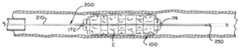
図1は、拡張構成における例示的な血管内処置装置の斜視図である。フレーム110は、血管内処置の一部として、カテーテルの内腔を通って収まるように畳み込まれ、血管内で拡張されてもよい。フレーム110は、フレームが図1に示したような所定の拡張された形状と、図2に示すような変形した畳み込まれた形状と、を有するように、形状記憶材料を含んでもよい。図3Aは、拡張されたときの血管内処置装置100の側面図であり、図3B及び図3Cは、図3Aに示すような拡張された血管内処置装置100の断面図である。図4Aは、畳み込まれたときの血管内処置装置100の側面図であり、図4B及び図4Cは、図4Aに示すような畳み込まれた血管内処置装置100の断面図である。1 is a perspective view of an exemplary endovascular treatment device in an expanded configuration. The
装置100が処置中に展開されるとき、フレーム110は、図2及び図4A~図4Cに示すような畳み込み構成から拡張構成、又は図1及び図3A~図3Cに示すような所定の形状に向かって拡張してもよい。フレーム110は、フレーム110が展開される血管の幾何学的形状によって、所定の形状に完全に拡張することが阻止される場合がある。いくつかの用途では、フレーム110は、有利には、血塊などの閉塞物を通って拡張してもよい。他の用途では、フレーム110は、血塊、プラーク、又は閉塞物によって、所定の形状に完全に拡張することが阻止される場合がある。したがって、フレーム110は、拡張構成の所定の形状に基づき、可能性としてはまた、フレーム110が展開される処置部位によっても成形される、血管内で拡張されたときの展開構成へ拡張してもよい。When the
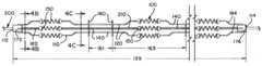
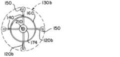
図1~図4Cをまとめて参照すると、装置の拡張可能なフレーム110は、屈曲ストラット120と、円形ストラット160と、直線状中央ストラット140と、を含んでもよい。装置100は、ガイドワイヤ210を含む送達システム200を含んでもよい。フレーム110の近位端部112は、ガイドワイヤ210に固着されてもよく、フレーム110の遠位端部114は、ガイドワイヤ210にわたって自由に摺動してもよい。フレーム110の近位端部112は、フレーム110をガイドワイヤ210に固着するために、接着剤、溶接、又は他の既知の取り付け様式などの取り付け機構172を含んでもよい。フレームの遠位端部114は、ガイドワイヤ210に沿って長手方向に摺動するように位置付けられた摺動カラー174を含んでもよい。Referring collectively to FIGS. 1-4C, the
図1及び図3A~図3Cに示すように、拡張構成又は展開構成において、円形ストラット160は、フレーム110の長さ138に沿って位置付けられてもよい。円形ストラット160は、ガイドワイヤ110を取り囲んでもよい。ガイドワイヤ110は、フレーム110を通ってフレームの中心軸線に沿って延びてもよく、それぞれの円形ストラット160によって作製された円の中心又はその付近で、それぞれの円形ストラット160を通過してもよい。円形ストラット160はそれぞれ、互いに平行で、フレーム110の中心軸線及びガイドワイヤ210に垂直な平面内で配向されてもよい。As shown in Figures 1 and 3A-3C, in an expanded or deployed configuration, the circular struts 160 may be positioned along the
それぞれの円形ストラット160は、最遠位の円形ストラット160及び最近位の円形ストラット160を除いて、近接する2つの隣接円形ストラット160、すなわち1つの遠位隣接ストラット及び1つの近位近傍ストラットを有してもよい。最遠位の円形ストラット160は、近位隣接ストラットのみを有してもよい。最近位の円形ストラット160は、遠位隣接ストラットのみを有してもよい。フレーム110は、それぞれの円形ストラット160をその隣接ストラットに接続する長手方向に延びるストラット140、120を含んでもよい。Each
拡張構成又は展開構成において、長手方向に延びるストラット140、120は、隣接する円形ストラット160と、隣接する円形ストラット160の間で径方向外側及び長手方向の両方に延びる屈曲ストラット120との間に延びる、本質的に直線状のコネクタである直線状ストラット140を含んでもよい。それぞれの円形ストラット160は、その隣接ストラットのうちの一方に直線状ストラット140によって接続され、その隣接ストラットのうちの他方に屈曲ストラット120によって接続されてもよい。In the expanded or deployed configuration, the
直線状ストラット140の群は、フレーム110が展開構成又は拡張構成にあるとき、フレーム110の内周134を画定するように、隣接する円形ストラット160の間に延びてもよい。隣接する円形ストラット160はそれぞれ、互いにほぼ等しい円周を有してもよい。隣接する円形ストラット160の間に延びる直線状ストラット140の群によって画定される内周134は、円形ストラット160の円周に等しいか、又はほぼ等しくてもよい。図1に示すように、直線状ストラット140の群はそれぞれ対応して、直線状ストラット140の他の群の全てによって画定される内周134とほぼ等しい内周134を画定してもよい。The groups of
直線状ストラット140の群によって接続された隣接する円形ストラット160は、フレーム110が拡張構成又は展開構成にあるとき、距離162だけ分離されてもよい。距離162は、隣接する円形ストラット160を接続する直線状ストラット140の群における、実質的に直線状のそれぞれのストラット140の長さとほぼ等しくてもよい。Adjacent
直線状ストラット140のそれぞれの群は、内周134の周りに等距離で位置付けられた4つの直線状ストラット140を含んでもよい。少ない場合には3つの直線状ストラット140及び多い場合には6つの直線状ストラット140が、直線状ストラット140の群を形成してもよいことが企図される。群内のより少ない直線状ストラット140は、血塊を通って延びるのを容易にするために、フレーム110により高い可撓性及びより大きい開口部を提供してもよい。群内のより多い直線状ストラット140は、血塊上の閉じ込め又は把持を増加させるために、より高い構造的一体性及びより小さい開口部を提供してもよい。Each group of
フレーム110は、直線状ストラット140の群の全てが等しい数の直線状ストラット140を含むように構築されてもよい。あるいは、フレーム110は、フレーム110の長さ138に沿ってフレーム110内における可撓性及び開口寸法を変化させるために、互いに異なる数の直線状ストラット140を有する直線状ストラット140の群を含むように構築されてもよい。例えば、装置100によって血塊が脈管構造を通って近位方向に引っ張られる際、より効果的に血塊を収容するために、フレーム110がより容易にフレーム110の遠位端部付近にある血塊及びより多い直線状ストラット140の群を通ってより容易に延びることができるように、長さ138の中央付近により少ない直線状ストラット140の群を有することが有利であってもよい。The
フレーム110が展開構成にあるとき、屈曲ストラット120はそれぞれ、円形ストラット160から径方向外側に延びて、約90°曲がり、ガイドワイヤ210に対して長手方向に実質的に平行に延びてもよいか、又は、フレーム110の中心軸線は、再び約90°曲がり、径方向内側に延びてもよい。屈曲ストラット120は、「U」字形として、「U」の脚部がフレーム110の中心線又はガイドワイヤ210から径方向に方向付けられ、「U」の凹部がフレーム中心線又はガイドワイヤ210から最も遠く離れて位置するようにしてもよい。When the
屈曲ストラット120のうちのいくつか又は全ての上に、放射線不透過性マーカーは、屈曲ストラット120に沿って中央に取り付けられてもよい。フレーム110が拡張構成又は展開構成にあるとき、放射線不透過性マーカーは、屈曲ストラット120のうちのいくつか又は全ての上で「U」字形の凹部に位置付けられてもよい。換言すれば、放射線不透過性マーカー150は、ガイドワイヤ210又はフレーム110の中心軸線に対して長手方向に、実質的に平行に延びるそれぞれの屈曲ストラット120の一部において、屈曲ストラット120のうちのいくつか又は全てに取り付けてもよい。On some or all of the bend struts 120, the radiopaque markers may be attached centrally along the bend struts 120. When the
フレーム110が展開構成にあるとき、屈曲ストラット120の群はそれぞれ、フレーム110のそれぞれ対応する外周130を画定するように延びてもよい。屈曲ストラットの群内の複数の屈曲ストラット120は、それに取り付けられた放射線不透過性マーカー150を含んで、放射線不透過性マーカー150が屈曲ストラットの群の円周130を示してもよい。When the
屈曲ストラット120のうちのいくつか又は全ては、ねじ山付きであってもよく、放射線不透過性マーカー150は、屈曲ストラット120上のねじ山にわたって嵌合するように成形されてもよい。Some or all of the bend struts 120 may be threaded and the
フレーム110は、屈曲ストラット120の互い違いの群と、フレーム110の長さ138に沿った直線状ストラット140の群と、を有してもよい。屈曲ストラット120の群はそれぞれ、直線状ストラット134のそれぞれの群によって画定されるそれぞれ対応する内周134よりも大きいそれぞれ対応する外周130を画定してもよい。フレーム110は、その結果、フレーム110の長さ138に沿って、屈曲ストラット120の群によって画定されるより大きい外周130と、直線状ストラット140の群によって画定されるより小さい内周134との間で互い違いになる可変円周を有してもよい。The
屈曲ストラット120のそれぞれの群は、外周130の周りに等距離に位置付けられた4つの屈曲ストラット120を含んでもよい。少ない場合には3つの屈曲ストラット120及び多い場合には6つの屈曲ストラット120が、屈曲ストラット120の群を形成してもよいことが企図される。群内のより少ない屈曲スラット120は、血塊を通って延びるのを容易にするために、より高い可撓性をフレーム110に提供してもよい。群内のより多い屈曲ストラット120は、血塊上の閉じ込め又は把持を増加させるために、より高い構造的一体性及びより小さい開口部を提供してもよい。Each group of
フレーム110は、屈曲ストラット120の群の全てが、等しい数の屈曲ストラット120を含むように構築されてもよい。あるいは、フレーム110は、フレーム110の長さ138に沿って、フレーム110における可撓性及び開口寸法を変化させるために、異なる数の屈曲ストラット120を有する屈曲ストラット120の群を含むように構築されてもよい。例えば、装置100によって血塊が脈管構造を通って近位方向に引っ張られる際、より効果的に血塊を収容するために、フレーム110がより容易にフレーム110の遠位端部付近にある血塊及び、より多い屈曲ストラット120の群を通ってより容易に延びることができるように、長さ138の中央付近により少ない屈曲ストラットの群を有することが有利であってもよい。The
屈曲ストラット120は、中央ストラット140と長手方向で位置合わせされて、フレーム110の長さ138の大部分に沿って連続的な長手方向延長部を形成してもよい。図1~図4Cは、4つの屈曲ストラット120及び3つの直線状ストラット140をそれぞれ含む、4つのこのような連続的な長手方向延長部を有するフレーム110を示す。屈曲ストラット120及び直線状ストラット140は、例示されるように交互の様式に位置付けられ、円形ストラット160への接続によって分離されてもよい。The bent struts 120 may be longitudinally aligned with the
フレーム110はまた、近位端部ストラット182及び遠位端部ストラット184を含んでもよい。近位端部ストラット182は、フレーム110を近位取り付けノード172に接続するように成形されてもよい。遠位端部ストラット184は、フレーム110を遠位摺動取り付け部174に接続するように成形されてもよい。近位端部ストラット182及び遠位端部ストラット184はそれぞれ、屈曲ストラット120及び直線状ストラット140と長手方向で位置合わせされてもよい。前述の連続的な長手方向延長部は、フレーム110の近位端部112にある近位端部ストラット182と、フレーム110の遠位端部114にある遠位端部ストラット184と、を含んでもよい。連続的な長手方向延長部は、その結果、拡張構成又は畳み込み構成においてフレーム110の長さ138、139の全体又は大部分を延長してもよい。The
送達構成/畳み込み構成において、フレーム110は、カテーテルの内腔を通って収まるように畳み込まれてもよい。畳み込み構成において、フレーム110は、拡張構成におけるフレーム110の長さ138と比較してより長い長さ139を有してもよい。In the delivery/folded configuration, the
円形ストラット160は、拡張構成における円形ストラット160の円周134よりも小さい畳み込まれた円周136へ畳み込まれてもよい。直線状ストラット140によって接続された隣接する円形ストラット160は、フレーム110が拡張構成にあるとき、フレーム110が環状ストラット160の間の距離162とほぼ等しい、畳み込み構成にあるときの距離161だけ分離されてもよい。屈曲ストラット120は、フレーム110が畳み込み構成にあるときに伸長されてもよい。屈曲ストラット120によって接続された隣接する円形ストラット160は、拡張構成又は展開構成において、フレーム110が隣接する円形ストラット160の間の長さ164よりも長い、畳み込み構成にあるときの距離163だけ分離されてもよい。フレーム110が畳み込み構成にあるとき、屈曲ストラット120の群はそれぞれ、拡張構成において、屈曲ストラット120のそれぞれ対応する群によって画定された円周130よりも小さい円周132を画定してもよい。The circular struts 160 may be folded into a folded
拡張構成におけるフレーム110の長さ138を畳み込み構成におけるフレーム110の長さ139と比較すると、畳み込み構成における長さ139は、屈曲ストラット120の長手方向の延長により、主に延長されてもよい。Comparing the
フレーム110は、図1及び図3A~図3Cに示すような例示された所定の形状並びに図2及び図4A~図4Cに示すような変形形状を有してもよい。フレーム110は、所定の形状にヒートセットされ、カテーテルを通って送達するために変形した形状に畳み込まれてもよい。フレーム110は、屈曲ストラット120を実質的に直線状に遠位方向に伸長させ、円形ストラット160を圧着することにより変形させてもよい。The
送達システム200は、その遠位端部に放射線不透過性コイル250を含んでもよい。図2及び図4A~図4Cに示すように、フレーム110の長さ139は、近位取り付けノード172と放射線不透過性コイル250との間のガイドワイヤ210に沿って延びてもよい。したがって、送達システム200は、屈曲ストラット120がカテーテルの内腔内に収まるために十分に折り畳むことができるように、フレーム110が延びることを可能にするのに十分な、近位取り付けノード172と放射線不透過性コイルとの間の距離により寸法決めされてもよい。The
装置100が展開されるとき、装置100は、図2及び図4A~図4Cに示すような変形形状から、図1及び図3A~図3Cに示すような所定の形状に向かって移動してもよい。フレーム110が畳み込み構成にあるときの屈曲ストラット120が実質的に直線状の状態から、フレーム110が拡張構成にあるときの「U」字形へ移動するとき、フレーム110の自由遠位端部114は、ガイドワイヤ210にわたって近位方向に摺動してもよい。所定の形状に向かって移動するとき、円形ストラット160は、径方向に拡張してもよい。When the
図5A~図5Dは、代替的な拡張構成又は展開構成を有する、例示的な血管内処置装置100aの図である。同様の参照番号は、図1~図4Cに示した装置100と図5A~図5Dに示した装置100aとの間で共通である類似又は同一の要素を示す。図5Aは、装置100aの側面図であり、図5B~図5Dは、図5Aに示したような装置100aの断面図である。FIGS. 5A-5D are diagrams of an exemplary endovascular treatment device 100a having alternative expanded or deployed configurations. Like reference numbers indicate similar or identical elements common between the
図1~図4Cに示した例示的な装置100を図5A~図5Dに示した例示的な装置100aと比較すると、図5A~図5Dの装置100aの拡張可能なフレーム110aは、異なる外周130a、130bを画定する屈曲ストラット120a、120bの群を含むが、一方で、図1~図4Cに示した屈曲ストラット120の群は、ほぼ等しい円周130を画定する。図5A~図5Dに示した装置100aは、第1の円周130aを画定する第1の群の屈曲ストラット120aと、第1の円周130aよりも小さい第2の円周130bを画定する第2の群の屈曲ストラット120bと、を含んでもよい。より小さい円周130bを画定する屈曲ストラット120bの群は、フレーム110aの長さ138に沿って中央に位置付けられてもよい。より小さい円周130bを画定する屈曲ストラット120bの群は、それぞれ対応してより大きい円周130aを画定する屈曲ストラット120aのうちの2つの群の間に位置付けられてもよい。Comparing the
より小さい円周130bをそれぞれ対応して画定する屈曲ストラット120bのうちの1つ以上の群をフレーム110aの長さ138に沿って中央に位置付けることが有利であってもよく、その結果、それらの群内の屈曲ストラット120bは、フレーム110aが畳み込まれているときに長手方向に遠くまで圧縮しないか、又はフレーム110aが拡張している際に径方向に遠くまで延びない。これにより、図1に示すような均等な大きさの屈曲ストラット120を有するフレーム110と比較して、送達構成において圧縮されたときの長さほどではないフレーム110aをもたらしてもよい。It may be advantageous to center one or more groups of
より小さい中央屈曲ストラット120bは、血塊上のより良好な把持を提供することができるより小さい開口部を、フレーム110a内に画定してもよい。フレーム110aの遠位端部112及び近位端部114におけるより大きい屈曲ストラット120aは、血塊を長手方向で収容するように機能してもよい。The smaller central
図5A~図5Dに示した装置100aは、図2に示した装置100に関連して説明されるものと同様に伸長かつ圧縮されてもよい。図5Aに示すように拡張されるとき、より大きい円周の第1の群の屈曲ストラット120aによって接続された隣接する円形ストラット160は、第1の距離164aだけ分離されてもよく、より小さい円周の第2の群の屈曲ストラット120bによって接続された隣接する円形ストラット160は、第2の距離164bだけ分離されてもよい。第1の距離164a及び第2の距離164bは、互いにほぼ等しくてもよい。フレーム110aがカテーテルを通って送達されるように畳み込まれるとき、屈曲ストラット120a、120bは、第1の群の屈曲ストラット120aによって接続された隣接する円形ストラット160が、第1の距離よりも長い第3の距離だけ分離されるように、第2の群の屈曲ストラット120bによって接続された隣接する円形ストラット160が、第2の距離よりも長く、かつ第3の距離よりも短い第4の距離だけ分離されるように、長手方向に延びてもよい。換言すれば、フレーム110aが送達構成にあるとき、第1の群の屈曲ストラット120aは、第2の群の屈曲ストラット120bよりも長くてもよく、屈曲ストラットの両方120a、120bの群は、拡張構成にあるときよりも長手方向に長くてもよい。The device 100a shown in Figures 5A-5D may be stretched and compressed in a manner similar to that described in connection with the
フレーム110aをマイクロカテーテル内に収まるように畳み込むことができるように、送達システム200は、フレーム110aが近位取り付けノード172と放射線不透過性コイル250との間で長手方向に拡張するのに十分な空間を有するような寸法にしてもよい。The
図6は、図1~図4Cに示したフレーム100と同様の構造を有する拡張可能なフレーム110cを有するステント100cの図である。同様の参照番号は、図1~図4Cに示した装置100と図6に示したステント100cとの間で共通である類似した又は同一の要素を示す。Figure 6 is an illustration of a
図1~図4Cに示した例示的な装置100を図6に示したステント100cと比較すると、図6のステント100cの拡張可能なフレーム110cは、ガイドワイヤ210に取り付けられる必要はなく、したがって、フレーム110cは、送達システム200、取り付け機構172、近位接続ストラット182、遠位摺動カラー174、及び遠位接続ストラット184を欠いて図示されている。フレーム110cの近位端部112c及び遠位端部114cは、示したような円形ストラット160によって、又は当業者によって認識されかつ理解されるように、他の拡張可能な構造及び/又は固定構造によって終端されてもよい。ストラット100cは、拡張構成において、フレーム110cの近位端部112cからフレームの遠位端部114cまで測定可能な、長さ138cを有してもよい。1-4C to the
いくつかの送達システムは、ステントを血管に送達することについて既知であり、このような送達システムは、本明細書では詳細に説明しない。ステント100cは、当業者によって認識されかつ理解されるように、送達システムによって送達されてもよい。ステント100cは、図2に示したものと類似のカテーテルを介して送達するために畳み込まれてもよい。Several delivery systems are known for delivering stents to blood vessels, and such delivery systems will not be described in detail herein.
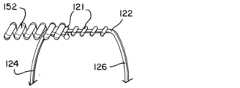
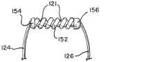
図7A~図7Cは、放射線不透過性マーカーアセンブリ150及びねじ山付き屈曲ストラット120の図である。本明細書で提示される例示的な装置100、100a、100cにおける屈曲ストラット120、120a、120bのうちのいくつか又は全ては、図7A~図7Cに示すようなねじ山121を含んでもよい。7A-7C are diagrams of a
放射線不透過性マーカー150は、螺旋コイル152及び端部取り付け部154、156を有してもよい。それぞれの螺旋コイル152は、図7Aに示すように、それぞれ対応する屈曲ストラット120のねじ山121上に巻き付けられてもよい。屈曲ストラット120は、第1のストラット脚部124と、第2のストラット脚部126と、第1のストラット脚部124と第2のストラット脚部126との間に延びるねじ山付き部分122を有するように屈曲されてもよい。屈曲部は、ストラット120のねじ山付き部分122から第1のストラット脚部124を分離してもよい。屈曲部は、図7Aに示すように、放射線不透過性マーカー150の螺旋コイル152がねじ山121上に巻き付けられるのを容易にするように成形されてもよい。The
螺旋コイル152が図7Bに示すように位置付けられると、コイル152の端部は、端部取り付け部154、156を用いてストラット120に固着されてもよい。端部取り付け部154、156は、溶接、接着剤、又は他の既知の取り付け部であってもよい。Once the
図8~図10は、血塊Cを捕捉する血管内処置装置100を示す。図8は、マイクロカテーテル内で畳み込まれ、血管を通って血塊Cに向かって送達されている装置100を示す。図9は、血塊Cを通過するマイクロカテーテル及び装置100を示す。図10は、血塊C内で後退されたマイクロカテーテル及び拡張された装置100を示す。Figures 8-10 show an
本明細書に含まれる記述は、本発明の実施形態の例であり、本発明の範囲を何ら制限するものではない。本明細書に記載されるように、本発明は、血管内処置の代替的な使用、代替材料、代替的な幾何形状、代替的な数の構成要素、代替的な送達機構などを含む、血管内処置装置の多くの変形及び修正を企図する。これらの修正は、本発明が関連する当業者には明らかであり、以下の特許請求の範囲内であることが意図される。The descriptions contained herein are examples of embodiments of the invention and are not intended to limit the scope of the invention in any way. As described herein, the invention contemplates many variations and modifications of the endovascular treatment device, including alternative uses of endovascular treatment, alternative materials, alternative geometries, alternative numbers of components, alternative delivery mechanisms, and the like. These modifications will be apparent to those skilled in the art to which the invention pertains and are intended to be within the scope of the following claims.
〔実施の態様〕
(1) 血管内処置装置であって、
細長いガイドと、
カテーテルの内腔を横断するように寸法決めされた畳み込み構成から、血管の内腔内に延びるように寸法決めされた拡張構成へ移動可能な拡張可能なフレームワークであって、前記拡張可能なフレームワークは、
複数の環状ストラットであって、それぞれの環状ストラットは、前記細長いガイドを取り囲み、それぞれの環状ストラットは、前記拡張可能なフレームワークが前記畳み込み構成にあるときの前記細長いガイドを中心とした収縮位置から、前記拡張可能なフレームワークが前記拡張構成にあるときの前記細長いガイドを中心とした径方向の拡張位置へ移動可能である、複数の環状ストラットと、
複数の中央ストラットであって、それぞれの中央ストラットは、それぞれの環状ストラットが前記複数の中央ストラットのうちの1つ以上の中央ストラットによって第1の隣接する環状ストラットのみに接合されるように、前記複数の環状ストラットのうちの2つの隣接する環状ストラットを接合し、それぞれの中央ストラットは、前記拡張可能なフレームワークが前記畳み込み構成にあるとき、前記拡張可能なフレームワークが前記拡張構成にあるときの前記中央ストラットの形状と本質的に同じである形状を備える、複数の中央ストラットと、
複数の屈曲ストラットであって、それぞれの屈曲ストラットは、それぞれの環状ストラットが、前記複数の屈曲ストラットのうちの1つ以上の屈曲ストラットによって、前記第1の隣接する環状ストラットとは反対側の第2の隣接する環状ストラットのみに接合されるように、前記複数の環状ストラットのうちの2つの隣接する環状ストラットを接合し、前記複数の屈曲ストラットのそれぞれは、前記拡張可能なフレームワークが前記畳み込み構成にあるときの長手方向に細長い形状から、前記拡張可能なフレームワークが前記拡張構成にあるときの径方向に拡張された形状へ移動可能である、複数の屈曲ストラットと、を含む、拡張可能なフレームワークと、を備える、血管内処置装置。
(2) 前記拡張可能なフレームワークが前記拡張構成にあるとき、
前記複数の屈曲ストラットのうちの第1の群の屈曲ストラットは、前記拡張可能なフレームワークの第1の円周を画定するように位置付けられ、
前記複数の中央ストラットのうちの第1の群の中央ストラットは、前記第1の円周よりも小さい寸法である前記拡張可能なフレームワークの第2の円周を画定するように位置付けられている、実施態様1に記載の装置。
(3) 前記拡張可能なフレームワークが前記拡張構成にあるとき、
前記複数の屈曲ストラットのうちの第2の群の屈曲ストラットは、前記第1の群の中央ストラットに隣接して位置付けられ、前記第1の円周にほぼ等しい前記拡張可能なフレームワークの第3の円周を画定するように位置付けられ、
前記複数の中央ストラットのうちの第2の群の中央ストラットは、前記第2の群の屈曲ストラットに隣接して位置付けられ、前記第2の円周にほぼ等しい前記拡張可能なフレームワークの第4の円周を画定するように位置付けられている、実施態様2に記載の装置。
(4) 前記第1の円周は、前記第2の円周の約2倍を超える寸法である、実施態様3に記載の装置。
(5) 前記拡張可能なフレームワークは、近位端部及び遠位端部を更に備え、
前記近位端部は、前記細長いガイドに固着され、
前記遠位端部は、前記細長いガイドにわたって摺動自在に移動可能である、実施態様1に記載の装置。[Embodiment]
(1) An intravascular treatment device, comprising:
A long guide and
an expandable framework movable from a collapsed configuration dimensioned to traverse a lumen of a catheter to an expanded configuration dimensioned to extend into a lumen of a blood vessel, the expandable framework comprising:
a plurality of annular struts, each annular strut surrounding the elongate guide, each annular strut movable from a contracted position about the elongate guide when the expandable framework is in the collapsed configuration to a radially expanded position about the elongate guide when the expandable framework is in the expanded configuration;
a plurality of central struts, each central strut joining two adjacent annular struts of the plurality of annular struts such that each annular strut is joined to only a first adjacent annular strut by one or more central struts of the plurality of central struts, each central strut having a shape when the expandable framework is in the collapsed configuration that is essentially the same as a shape of the central strut when the expandable framework is in the expanded configuration;
and an expandable framework including a plurality of bent struts, each bent strut joining two adjacent annular struts of the plurality of bent struts such that each annular strut is joined by one or more bent struts of the plurality of bent struts only to a second adjacent annular strut opposite the first adjacent annular strut, each of the plurality of bent struts being movable from a longitudinally elongated shape when the expandable framework is in the collapsed configuration to a radially expanded shape when the expandable framework is in the expanded configuration.
(2) when the extensible framework is in the extended configuration,
a first group of bent struts of the plurality of bent struts positioned to define a first circumference of the expandable framework;
2. The device of
(3) when the extensible framework is in the extended configuration,
a second group of bent struts of the plurality of bent struts are positioned adjacent to a central strut of the first group and positioned to define a third circumference of the expandable framework approximately equal to the first circumference;
The device of claim 2, wherein a second group of central struts among the plurality of central struts are positioned adjacent to the second group of bent struts and positioned to define a fourth circumference of the expandable framework approximately equal to the second circumference.
4. The device of claim 3, wherein the first circumference is greater than about twice the dimension of the second circumference.
(5) The expandable framework further comprises a proximal end and a distal end,
the proximal end is secured to the elongate guide;
2. The device of
(6) 複数の放射線不透過性マーカーを更に備え、
屈曲ストラットの少なくとも一部のそれぞれは、ねじ山を備え、
前記複数の放射線不透過性マーカーのうちの前記放射線不透過性マーカーのそれぞれは、前記ねじ山によって前記屈曲ストラットの前記少なくとも一部のそれぞれに固定されている、実施態様1に記載の装置。
(7) 複数の放射線不透過性マーカーを更に備え、
前記複数の放射線不透過性マーカーのうちの第1の群は、前記第1の円周を画定するように前記第1の群の屈曲ストラット上に位置付けられ、
前記複数の放射線不透過性マーカーのうちの第2の群は、前記第3の円周を画定するように前記第2の群の屈曲ストラット上に位置付けられている、実施態様3に記載の装置。
(8) 前記拡張構成において、前記拡張可能なフレームワークは、遠位端部と、近位端部と、前記遠位端部から前記近位端部まで測定可能な長さと、前記フレームワークの前記長さの少なくとも一部に沿って、第1の円周から前記第1の円周よりも小さい寸法の第2の円周へ、前記第2の円周から前記第2の円周よりも大きく前記第1の円周以下の寸法の第3の円周へ、前記第3の円周から再び前記第2の円周へ移行する可変円周と、を備える、実施態様1に記載の装置。
(9) 前記拡張構成において、第3の円周は、前記第1の円周よりも小さい寸法であり、
前記拡張構成において、前記第1の円周は、前記複数の屈曲ストラットのうちの第1の群の屈曲ストラットによって画定され、前記第2の円周は、径方向に拡張された2つの隣接する環状ストラットと、前記径方向に拡張された2つの隣接する環状ストラットを接合する1つ以上の中央ストラットと、によって画定され、前記第3の円周は、第2の群の屈曲ストラットによって画定されている、実施態様8に記載の装置。
(10) カテーテルの内腔を横断するように寸法決めされた送達構成から、血管の内腔内に延びるように寸法決めされた展開構成へ移動可能な拡張可能な血塊捕捉装置であって、前記装置は、
複数の環状ストラットであって、それぞれの環状ストラットは、前記血塊捕捉装置が前記送達構成にあるときの収縮した円周から、前記血塊捕捉装置が前記展開構成にあるときの拡張した円周へ移動可能である、複数の環状ストラットと、
複数の中央ストラットであって、それぞれの中央ストラットは、前記血塊捕捉装置が前記送達構成にあるとき、前記血塊捕捉装置が前記展開構成にあるときの前記中央ストラットの形状と本質的に同じである形状を備える、複数の中央ストラットと、
複数の屈曲ストラットであって、前記複数の屈曲ストラットのそれぞれは、前記装置が前記送達構成にあるときの長手方向に細長い形状から、前記血塊捕捉装置が前記展開構成にあるときの径方向に拡張された形状へ移動可能である、複数の屈曲ストラットと、を備え、
前記複数の環状ストラットのうちの少なくとも一部はそれぞれ、第1の隣接する環状ストラットと、前記第1の隣接する環状ストラットの反対側の第2の隣接する環状ストラットと、に接合され、
前記複数の環状ストラットのうちの前記少なくとも一部のそれぞれは、前記複数の中央ストラットのうちの1つ以上の中央ストラットによって、前記関連する第1の隣接する環状ストラットに接合され、
前記複数の環状ストラットのうちの前記少なくとも一部のそれぞれは、前記複数の屈曲ストラットのうちの1つ以上の屈曲ストラットの群によって前記第2の隣接する環状ストラットに接合されている、拡張可能な血塊捕捉装置。(6) further comprising a plurality of radiopaque markers;
At least some of the bending struts each include a thread;
2. The device of
(7) further comprising a plurality of radiopaque markers;
a first group of the plurality of radiopaque markers positioned on the first group of bent struts to define the first circumference;
4. The device of claim 3, wherein a second group of the plurality of radiopaque markers are positioned on the second group of bent struts to define the third circumference.
8. The device of
(9) In the expanded configuration, the third circumference is smaller than the first circumference,
9. The device of claim 8, wherein in the expanded configuration, the first circumference is defined by a first group of bent struts of the plurality of bent struts, the second circumference is defined by two adjacent radially expanded annular struts and one or more central struts joining the two adjacent radially expanded annular struts, and the third circumference is defined by the second group of bent struts.
(10) An expandable clot capture device movable from a delivery configuration dimensioned to traverse a lumen of a catheter to a deployed configuration dimensioned to extend into a lumen of a blood vessel, the device comprising:
a plurality of annular struts, each annular strut movable from a contracted circumference when the clot capture device is in the delivery configuration to an expanded circumference when the clot capture device is in the deployed configuration;
a plurality of central struts, each central strut comprising a shape when the clot capture device is in the delivery configuration that is essentially the same as a shape of the central strut when the clot capture device is in the deployed configuration;
a plurality of bent struts, each of the plurality of bent struts movable from a longitudinally elongated shape when the device is in the delivery configuration to a radially expanded shape when the clot capture device is in the deployed configuration;
at least some of the plurality of annular struts are each joined to a first adjacent annular strut and a second adjacent annular strut opposite the first adjacent annular strut;
each of the at least some of the plurality of annular struts is joined to an associated first adjacent annular strut by one or more central struts of the plurality of central struts;
An expandable clot capture device, wherein each of the at least some of the plurality of annular struts is joined to a second adjacent annular strut by a group of one or more bent struts of the plurality of bent struts.
(11) 前記血塊捕捉装置が前記展開構成にあるとき、前記1つ以上の屈曲ストラットのそれぞれの群は、それぞれの円周を画定し、
前記血塊捕捉装置が前記展開構成にあるとき、それぞれの環状ストラットの前記拡張した円周は、前記1つ以上の屈曲ストラットのそれぞれの群のそれぞれ対応する円周よりも小さい寸法である、実施態様10に記載の拡張可能な血塊捕捉装置。
(12) 前記血塊捕捉装置が前記展開構成にあるとき、1つ以上の屈曲ストラットの第1の群は、第1の円周を画定し、1つ以上の屈曲ストラットの第2の群は、前記第1の円周にほぼ等しい第2の円周を画定し、前記第1の群の遠位かつ第2の群の近位に位置付けられた1つ以上の屈曲ストラットの第3の群は、前記第1の円周及び前記第2の円周よりも小さい寸法であり、それぞれの環状ストラットの前記拡張した円周よりも大きい寸法である第3の円周を備える、実施態様11に記載の拡張可能な血塊捕捉装置。
(13) 前記複数の環状ストラットの前記少なくとも一部のそれぞれは、前記血塊捕捉装置が前記送達構成にあるときに第1の距離だけ、前記血塊捕捉装置が前記展開構成にあるときに第2の距離だけ、それぞれの第1の隣接する環状ストラットから分離され、前記第1の距離は、前記第2の距離にほぼ等しく、
前記複数の環状ストラットの前記少なくとも一部のそれぞれは、前記血塊捕捉装置が前記送達構成にあるときに第3の距離だけ、前記血塊捕捉装置が前記展開構成にあるときに第4の距離だけ、それぞれの第2の隣接する環状ストラットから分離され、前記第3の距離は、前記第4の距離よりも長い、実施態様10に記載の拡張可能な血塊捕捉装置。
(14) 複数の放射線不透過性マーカーを更に備え、前記屈曲ストラットの少なくとも一部は、前記屈曲ストラットの前記少なくとも一部に取り付けられた、前記複数の放射線不透過性マーカーのうちの放射線不透過性マーカーを備え、
前記複数の放射線不透過性マーカーは、前記血塊捕捉装置が前記送達構成にあるときに、前記血塊捕捉装置の畳み込まれた円周の表示を、前記血塊捕捉装置が前記展開構成にあるときに、前記血塊捕捉装置の拡張された円周の表示を、提供する、実施態様11に記載の拡張可能な血塊捕捉装置。
(15) 屈曲ストラットの前記少なくとも一部のそれぞれは、ねじ山を備え、前記複数の放射線不透過性マーカーのうちの前記放射線不透過性マーカーのそれぞれは、前記ねじ山によって前記屈曲ストラットの前記少なくとも一部のそれぞれに固定されている、実施態様14に記載の拡張可能な血塊捕捉装置。(11) When the clot capture device is in the deployed configuration, each group of the one or more bent struts defines a respective circumference;
An expandable clot capture device as described in claim 10, wherein when the clot capture device is in the deployed configuration, the expanded circumference of each annular strut is smaller than the corresponding circumference of each group of the one or more bent struts.
12. The expandable clot capture device of claim 11, wherein when the clot capture device is in the deployed configuration, a first group of one or more bent struts defines a first circumference, a second group of one or more bent struts defines a second circumference approximately equal to the first circumference, and a third group of one or more bent struts positioned distal to the first group and proximal to the second group comprises a third circumference that is a smaller dimension than the first and second circumferences and a larger dimension than the expanded circumference of a respective annular strut.
(13) each of the at least some of the plurality of annular struts is separated from a respective first adjacent annular strut by a first distance when the clot capture device is in the delivery configuration and by a second distance when the clot capture device is in the deployed configuration, the first distance being approximately equal to the second distance;
An expandable clot capture device as described in claim 10, wherein each of at least a portion of the plurality of annular struts is separated from a respective second adjacent annular strut by a third distance when the clot capture device is in the delivery configuration and by a fourth distance when the clot capture device is in the deployed configuration, the third distance being greater than the fourth distance.
(14) The method further comprising: providing a plurality of radiopaque markers; and wherein at least a portion of the bend struts includes a radiopaque marker of the plurality of radiopaque markers attached to the at least a portion of the bend struts.
An expandable clot capture device as described in embodiment 11, wherein the plurality of radiopaque markers provide an indication of a folded circumference of the clot capture device when the clot capture device is in the delivery configuration and an indication of an expanded circumference of the clot capture device when the clot capture device is in the deployed configuration.
15. The expandable clot capture device of claim 14, wherein each of the at least a portion of the bent struts comprises a thread, and each of the radiopaque markers of the plurality of radiopaque markers is secured to each of the at least a portion of the bent struts by the thread.
(16) 前記血塊捕捉装置は、
前記複数の環状ストラットと、前記複数の中央ストラットと、前記複数の屈曲ストラットと、を含む、拡張可能なフレームと、
前記拡張可能なフレームの中心軸線を通って延び、前記拡張可能なフレームの近位端部に近接する単一のノードで前記拡張可能なフレームに固着される、ガイドワイヤと、を更に備える、実施態様10に記載の拡張可能な血塊捕捉装置。
(17) 方法であって、
ガイドワイヤを取り囲むように拡張可能なフレームを位置付けることと、
前記フレームの近位端部に近接する取り付け部位において、前記フレームを前記ガイドワイヤに取り付けることと、
前記フレームがカテーテルの内腔を横断するように寸法決めされた送達構成にあるように、前記ガイドワイヤを中心として前記フレームを畳み込むことと、
前記フレームを前記送達構成から展開構成に拡張させることと、
前記フレームが前記送達構成から前記展開構成へ拡張する際、前記取り付け部位における前記ガイドワイヤへの前記フレームの前記取り付けを維持することと、
前記フレームが前記送達構成から前記展開構成へ拡張する際、前記フレームの少なくとも一部を前記ガイドワイヤにわたって摺動させることと、
前記遠位端部から前記近位端部まで測定可能な長さと、前記フレームの前記長さの少なくとも一部に沿って、第1の円周から前記第1の円周の半分よりも小さい寸法の第2の円周へ、前記第2の円周から前記第2の円周よりも大きく前記第1の円周以下の寸法の第3の円周へ、前記第3の円周から再び前記第2の円周へ移行する可変円周と、を備えるように、前記フレームを前記展開構成において成形することと、を含む、方法。
(18) 複数の環状ストラットと、複数の長手方向ストラットと、複数の屈曲可能なストラットと、から前記フレームを形成することと、
前記ガイドワイヤを取り囲むように、それぞれの環状ストラットを位置付けることと、
それぞれの環状ストラットが、第1の隣接する近傍環状ストラット及び第2の隣接する近傍環状ストラットを有するように、前記複数の環状ストラットを、前記フレームの長さに沿って間隔を空けることと、
前記複数の長手方向ストラットのうちの1つ以上の長手方向ストラットによって、それぞれの環状ストラットを、前記それぞれの環状ストラットの第1の隣接する近傍環状ストラットに接続することと、
前記複数の屈曲可能なストラットのうちの1つ以上の屈曲可能なストラットによって、それぞれの環状ストラットを、前記それぞれの環状ストラットの第2の隣接する近傍環状ストラットに接続することと、を更に含み、
前記フレームを前記送達構成から前記展開構成に拡張させる前記工程は、
前記フレームが前記送達構成から前記展開構成へ拡張する際、前記複数の環状ストラットのうちのそれぞれの環状ストラットを前記ガイドワイヤから径方向に離れるように拡張させることと、
前記フレームが前記送達構成から前記展開構成へ拡張する際、前記複数の長手方向ストラットのうちのそれぞれの長手方向ストラットの本質的に一定の形状を維持することであって、前記フレームが前記送達構成にあるときの前記それぞれの長手方向ストラットの形状は、前記フレームが前記展開構成となった後に本質的に変化しない、ことと、
前記フレームが前記送達構成から前記展開構成へ拡張する際、前記複数の屈曲可能なストラットのうちのそれぞれの屈曲可能なストラットを、前記ガイドワイヤから径方向に離れるように延ばすことと、を更に含む、実施態様17に記載の方法。
(19) 血塊内の前記フレームの少なくとも一部を拡張させることと、
前記フレーム内の前記血塊の少なくとも一部を捕捉することと、を更に含む、実施態様17に記載の方法。
(20) 前記フレームが前記展開構成にあるとき、前記第1の円周及び前記第3の円周の表示を提供するように、複数の放射線不透過性マーカーを位置付けることを更に含む、実施態様17に記載の方法。(16) The blood clot capture device comprises:
an expandable frame comprising the plurality of annular struts, the plurality of central struts, and the plurality of bent struts;
11. The expandable clot capture device of claim 10, further comprising a guidewire extending through a central axis of the expandable frame and secured to the expandable frame at a single node proximate the proximal end of the expandable frame.
(17) A method comprising the steps of:
Positioning an expandable frame around a guidewire;
attaching the frame to the guidewire at an attachment site proximate a proximal end of the frame;
collapsing the frame about the guidewire such that the frame is in a delivery configuration dimensioned to traverse a lumen of a catheter;
Expanding the frame from the delivery configuration to a deployed configuration;
maintaining the attachment of the frame to the guidewire at the attachment site as the frame expands from the delivery configuration to the deployed configuration;
sliding at least a portion of the frame over the guidewire as the frame expands from the delivery configuration to the deployed configuration;
and shaping the frame in the expanded configuration to have a measurable length from the distal end to the proximal end and a variable circumference along at least a portion of the length of the frame, transitioning from a first circumference to a second circumference having a dimension less than half of the first circumference, to a third circumference having a dimension greater than the second circumference and less than or equal to the first circumference, and from the third circumference back to the second circumference.
(18) forming the frame from a plurality of annular struts, a plurality of longitudinal struts, and a plurality of bendable struts;
Positioning each annular strut so as to surround the guidewire;
spacing the plurality of annular struts along a length of the frame such that each annular strut has a first adjacent neighboring annular strut and a second adjacent neighboring annular strut;
connecting a respective annular strut to a first adjacent neighboring annular strut of the respective annular strut by one or more longitudinal struts of the plurality of longitudinal struts;
connecting each annular strut to a second adjacent neighboring annular strut of the each annular strut by one or more bendable struts of the plurality of bendable struts;
The step of expanding the frame from the delivery configuration to the deployed configuration comprises:
expanding each annular strut of the plurality of annular struts radially away from the guidewire as the frame expands from the delivery configuration to the deployed configuration;
maintaining an essentially constant shape of each longitudinal strut of the plurality of longitudinal struts as the frame expands from the delivery configuration to the deployed configuration, wherein a shape of each longitudinal strut when the frame is in the delivery configuration does not essentially change after the frame is in the deployed configuration;
18. The method of claim 17, further comprising extending each bendable strut of the plurality of bendable struts radially away from the guidewire as the frame expands from the delivery configuration to the deployed configuration.
(19) Expanding at least a portion of the frame within a clot;
18. The method of claim 17, further comprising capturing at least a portion of the clot within the frame.
20. The method of claim 17, further comprising positioning a plurality of radiopaque markers to provide an indication of the first circumference and the third circumference when the frame is in the deployed configuration.
Claims (16)
Translated fromJapanese細長いガイドと、
カテーテルの内腔を横断するように寸法決めされた畳み込み構成から、血管の内腔内に延びるように寸法決めされた拡張構成へ移動可能な拡張可能なフレームワークであって、前記拡張可能なフレームワークは、
複数の環状ストラットであって、それぞれの環状ストラットは、前記細長いガイドを取り囲み、それぞれの環状ストラットは、前記拡張可能なフレームワークが前記畳み込み構成にあるときの前記細長いガイドを中心とした収縮位置から、前記拡張可能なフレームワークが前記拡張構成にあるときの前記細長いガイドを中心とした径方向の拡張位置へ移動可能である、複数の環状ストラットと、
複数の中央ストラットであって、それぞれの中央ストラットは、それぞれの環状ストラットが前記複数の中央ストラットのうちの1つ以上の中央ストラットによって第1の隣接する環状ストラットのみに接合されるように、前記複数の環状ストラットのうちの2つの隣接する環状ストラットを接合し、それぞれの中央ストラットは、前記拡張可能なフレームワークが前記畳み込み構成にあるとき、前記拡張可能なフレームワークが前記拡張構成にあるときの前記中央ストラットの形状と本質的に同じである形状を備える、複数の中央ストラットと、
複数の屈曲ストラットであって、それぞれの屈曲ストラットは、それぞれの環状ストラットが、前記複数の屈曲ストラットのうちの1つ以上の屈曲ストラットによって、前記第1の隣接する環状ストラットとは反対側の第2の隣接する環状ストラットのみに接合されるように、前記複数の環状ストラットのうちの2つの隣接する環状ストラットを接合し、前記複数の屈曲ストラットのそれぞれは、前記拡張可能なフレームワークが前記畳み込み構成にあるときの長手方向に細長い形状から、前記拡張可能なフレームワークが前記拡張構成にあるときの径方向に拡張された形状へ移動可能である、複数の屈曲ストラットと、を含む、拡張可能なフレームワークと、を備える、血管内処置装置。 An intravascular treatment device, comprising:
A long guide and
an expandable framework movable from a collapsed configuration dimensioned to traverse a lumen of a catheter to an expanded configuration dimensioned to extend into a lumen of a blood vessel, the expandable framework comprising:
a plurality of annular struts, each annular strut surrounding the elongate guide, each annular strut movable from a contracted position about the elongate guide when the expandable framework is in the collapsed configuration to a radially expanded position about the elongate guide when the expandable framework is in the expanded configuration;
a plurality of central struts, each central strut joining two adjacent annular struts of the plurality of annular struts such that each annular strut is joined to only a first adjacent annular strut by one or more central struts of the plurality of central struts, each central strut having a shape when the expandable framework is in the collapsed configuration that is essentially the same as a shape of the central strut when the expandable framework is in the expanded configuration;
and an expandable framework including a plurality of bent struts, each bent strut joining two adjacent annular struts of the plurality of bent struts such that each annular strut is joined by one or more bent struts of the plurality of bent struts only to a second adjacent annular strut opposite the first adjacent annular strut, each of the plurality of bent struts being movable from a longitudinally elongated shape when the expandable framework is in the collapsed configuration to a radially expanded shape when the expandable framework is in the expanded configuration.
前記複数の屈曲ストラットのうちの第1の群の屈曲ストラットは、前記拡張可能なフレームワークの第1の円周を画定するように位置付けられ、
前記複数の中央ストラットのうちの第1の群の中央ストラットは、前記第1の円周よりも小さい寸法である前記拡張可能なフレームワークの第2の円周を画定するように位置付けられている、請求項1に記載の血管内処置装置。 When the extensible framework is in the extended configuration:
a first group of bent struts of the plurality of bent struts positioned to define a first circumference of the expandable framework;
2. The intravascular treatment device of claim 1, wherein a first group of central struts of theplurality of central struts are positioned to define a second circumference of the expandable framework that is sized smaller than the first circumference.
前記複数の屈曲ストラットのうちの第2の群の屈曲ストラットは、前記第1の群の中央ストラットに隣接して位置付けられ、前記第1の円周にほぼ等しい前記拡張可能なフレームワークの第3の円周を画定するように位置付けられ、
前記複数の中央ストラットのうちの第2の群の中央ストラットは、前記第2の群の屈曲ストラットに隣接して位置付けられ、前記第2の円周にほぼ等しい前記拡張可能なフレームワークの第4の円周を画定するように位置付けられている、請求項2に記載の血管内処置装置。 When the extensible framework is in the extended configuration:
a second group of bent struts of the plurality of bent struts are positioned adjacent to a central strut of the first group and positioned to define a third circumference of the expandable framework approximately equal to the first circumference;
3. The intravascular treatment device of claim 2, wherein a second group of central struts of theplurality of central struts are positioned adjacent to the second group of bent struts and positioned to define a fourth circumference of the expandable framework approximately equal to the second circumference.
前記近位端部は、前記細長いガイドに固着され、
前記遠位端部は、前記細長いガイドにわたって摺動自在に移動可能である、請求項1に記載の血管内処置装置。 the expandable framework further comprises a proximal end and a distal end;
the proximal end is secured to the elongate guide;
Theintravascular treatment device of claim 1 , wherein the distal end is slidably moveable over the elongate guide.
屈曲ストラットの少なくとも一部のそれぞれは、ねじ山を備え、
前記複数の放射線不透過性マーカーのうちの前記放射線不透過性マーカーのそれぞれは、前記ねじ山によって前記屈曲ストラットの前記少なくとも一部のそれぞれに固定されている、請求項1に記載の血管内処置装置。 a plurality of radiopaque markers;
At least some of the bending struts each include a thread;
The endovascular treatment device of claim 1 , wherein each of the radiopaque markers of the plurality of radiopaque markers is secured to each of the at least a portion of the bent struts by the threads.
前記複数の放射線不透過性マーカーのうちの第1の群は、前記第1の円周を画定するように前記第1の群の屈曲ストラット上に位置付けられ、
前記複数の放射線不透過性マーカーのうちの第2の群は、前記第3の円周を画定するように前記第2の群の屈曲ストラット上に位置付けられている、請求項3に記載の血管内処置装置。 a plurality of radiopaque markers;
a first group of the plurality of radiopaque markers positioned on the first group of bent struts to define the first circumference;
The intravascular treatment device of claim 3 , wherein a second group of the plurality of radiopaque markers are positioned on the second group of bent struts to define the third circumference.
前記拡張構成において、前記第1の円周は、前記複数の屈曲ストラットのうちの第1の群の屈曲ストラットによって画定され、前記第2の円周は、径方向に拡張された2つの隣接する環状ストラットと、前記径方向に拡張された2つの隣接する環状ストラットを接合する1つ以上の中央ストラットと、によって画定され、前記第3の円周は、第2の群の屈曲ストラットによって画定されている、請求項8に記載の血管内処置装置。 in the expanded configuration, thethird circumference is a smaller dimension than the first circumference;
9. The intravascular treatment device of claim 8, wherein in the expanded configuration, the first circumference is defined by a first group of bent struts of the plurality of bent struts, the second circumference is defined by two adjacent radially expanded annular struts and one or more central struts joining the two adjacentradially expanded annular struts, and the third circumference is defined by a second group of bent struts.
複数の環状ストラットであって、それぞれの環状ストラットは、前記血塊捕捉装置が前記送達構成にあるときの収縮した円周から、前記血塊捕捉装置が前記展開構成にあるときの拡張した円周へ移動可能である、複数の環状ストラットと、
複数の中央ストラットであって、それぞれの中央ストラットは、前記血塊捕捉装置が前記送達構成にあるとき、前記血塊捕捉装置が前記展開構成にあるときの前記中央ストラットの形状と本質的に同じである形状を備える、複数の中央ストラットと、
複数の屈曲ストラットであって、前記複数の屈曲ストラットのそれぞれは、前記血塊捕捉装置が前記送達構成にあるときの長手方向に細長い形状から、前記血塊捕捉装置が前記展開構成にあるときの径方向に拡張された形状へ移動可能である、複数の屈曲ストラットと、を備え、
前記複数の環状ストラットのうちの少なくとも一部はそれぞれ、第1の隣接する環状ストラットと、前記第1の隣接する環状ストラットの反対側の第2の隣接する環状ストラットと、に接合され、
前記複数の環状ストラットのうちの前記少なくとも一部のそれぞれは、前記複数の中央ストラットのうちの1つ以上の中央ストラットによって、前記第1の隣接する環状ストラットに接合され、
前記複数の環状ストラットのうちの前記少なくとも一部のそれぞれは、前記複数の屈曲ストラットのうちの1つ以上の屈曲ストラットの群によって前記第2の隣接する環状ストラットに接合されている、拡張可能な血塊捕捉装置。 1. An expandable clot capture device movable from a delivery configuration dimensioned to traverse a lumen of a catheter to a deployed configuration dimensioned to extend into a lumen of a blood vessel, theclot capture device comprising:
a plurality of annular struts, each annular strut movable from a contracted circumference when the clot capture device is in the delivery configuration to an expanded circumference when the clot capture device is in the deployed configuration;
a plurality of central struts, each central strut comprising a shape when the clot capture device is in the delivery configuration that is essentially the same as a shape of the central strut when the clot capture device is in the deployed configuration;
a plurality of bent struts, each of the plurality of bent struts movable from a longitudinally elongated shape when theclot capture device is in the delivery configuration to a radially expanded shape when the clot capture device is in the deployed configuration;
at least some of the plurality of annular struts are each joined to a first adjacent annular strut and a second adjacent annular strut opposite the first adjacent annular strut;
each of the at least some of the plurality of annular struts is joined toa first adjacent annular strut by one or more central struts of the plurality of central struts;
An expandable clot capture device, wherein each of the at least some of the plurality of annular struts is joined to a second adjacent annular strut by a group of one or more bent struts of the plurality of bent struts.
前記血塊捕捉装置が前記展開構成にあるとき、それぞれの環状ストラットの前記拡張した円周は、前記1つ以上の屈曲ストラットのそれぞれの群のそれぞれ対応する円周よりも小さい寸法である、請求項10に記載の拡張可能な血塊捕捉装置。 when the clot capture device is in the deployed configuration, each group of the one or more bent struts defines a respective circumference;
The expandable clot capture device of claim 10 , wherein when the clot capture device is in the deployed configuration, the expanded circumference of each annular strut is dimensioned to be less than a corresponding circumference of each group of the one or more bent struts.
前記複数の環状ストラットの前記少なくとも一部のそれぞれは、前記血塊捕捉装置が前記送達構成にあるときに第3の距離だけ、前記血塊捕捉装置が前記展開構成にあるときに第4の距離だけ、それぞれの第2の隣接する環状ストラットから分離され、前記第3の距離は、前記第4の距離よりも長い、請求項10に記載の拡張可能な血塊捕捉装置。 each of the at least some of the plurality of annular struts is separated from a respective first adjacent annular strut by a first distance when the clot capture device is in the delivery configuration and by a second distance when the clot capture device is in the deployed configuration, the first distance being approximately equal to the second distance;
11. The expandable clot capture device of claim 10, wherein each of the at least some of the plurality of annular struts is separated from a respective second adjacent annular strut by a third distance when the clot capture device is in the delivery configuration and by a fourth distance when the clot capture device is in the deployed configuration, the third distance being greater than the fourth distance.
前記複数の放射線不透過性マーカーは、前記血塊捕捉装置が前記送達構成にあるときに、前記血塊捕捉装置の畳み込まれた円周の表示を、前記血塊捕捉装置が前記展開構成にあるときに、前記血塊捕捉装置の拡張された円周の表示を、提供する、請求項11に記載の拡張可能な血塊捕捉装置。 a plurality of radiopaque markers, at least a portion of the bend struts comprising a radiopaque marker of the plurality of radiopaque markers attached to the at least a portion of the bend struts;
The expandable clot capture device of claim 11, wherein the plurality of radiopaque markers provide an indication of a collapsed circumference of the clot capture device when the clot capture device is in the delivery configuration and an indication of an expanded circumference of the clot capture device when the clot capture device is in the deployed configuration.
前記複数の環状ストラットと、前記複数の中央ストラットと、前記複数の屈曲ストラットと、を含む、拡張可能なフレームと、
前記拡張可能なフレームの中心軸線を通って延び、前記拡張可能なフレームの近位端部に近接する単一のノードで前記拡張可能なフレームに固着される、ガイドワイヤと、を更に備える、請求項10に記載の拡張可能な血塊捕捉装置。 The clot capture device comprises:
an expandable frame comprising the plurality of annular struts, the plurality of central struts, and the plurality of bent struts;
11. The expandable clot capture device of claim 10, further comprising a guidewire extending through a central axis of the expandable frame and anchored to the expandable frame at a single node proximate a proximal end of the expandable frame.
Applications Claiming Priority (2)
| Application Number | Priority Date | Filing Date | Title |
|---|---|---|---|
| US16/441,389 | 2019-06-14 | ||
| US16/441,389US11109939B2 (en) | 2019-06-14 | 2019-06-14 | Intravascular devices with radiopaque body markers |
Publications (2)
| Publication Number | Publication Date |
|---|---|
| JP2020203087A JP2020203087A (en) | 2020-12-24 |
| JP7609364B2true JP7609364B2 (en) | 2025-01-07 |
Family
ID=71094130
Family Applications (1)
| Application Number | Title | Priority Date | Filing Date |
|---|---|---|---|
| JP2020102120AActiveJP7609364B2 (en) | 2019-06-14 | 2020-06-12 | Intravascular device with radiopaque body markers - Patents.com |
Country Status (7)
| Country | Link |
|---|---|
| US (2) | US11109939B2 (en) |
| EP (1) | EP3750491A1 (en) |
| JP (1) | JP7609364B2 (en) |
| CN (1) | CN112075971B (en) |
| AU (1) | AU2020203028A1 (en) |
| BR (1) | BR102020010814A2 (en) |
| CA (1) | CA3080742A1 (en) |
Families Citing this family (5)
| Publication number | Priority date | Publication date | Assignee | Title |
|---|---|---|---|---|
| US12285182B2 (en) | 2018-10-10 | 2025-04-29 | Innova Vascular, Inc. | Devices and methods for removing an embolus |
| JP6967571B2 (en)* | 2019-11-15 | 2021-11-17 | 株式会社Biomedical Solutions | Stent |
| US20230210545A1 (en)* | 2021-12-30 | 2023-07-06 | Deepin Technologies, LLC. | Expandable intraluminal device |
| WO2023173107A2 (en)* | 2022-03-10 | 2023-09-14 | Innova Vascular, Inc. | Torqueable devices and methods for removing an embolus |
| WO2025120471A1 (en)* | 2023-12-03 | 2025-06-12 | Phenox Gmbh | Devices and methods for treating blocked blood vessels |
Citations (2)
| Publication number | Priority date | Publication date | Assignee | Title |
|---|---|---|---|---|
| US20130345739A1 (en) | 2011-03-09 | 2013-12-26 | Neuravi Limited | Clot retrieval device for removing occlusive clot from a blood vessel |
| US20140277079A1 (en) | 2013-03-14 | 2014-09-18 | Neuravi Limited | Clot retrieval devices |
Family Cites Families (156)
| Publication number | Priority date | Publication date | Assignee | Title |
|---|---|---|---|---|
| US20070282443A1 (en)* | 1997-03-07 | 2007-12-06 | Disc-O-Tech Medical Technologies Ltd. | Expandable element |
| IL128261A0 (en)* | 1999-01-27 | 1999-11-30 | Disc O Tech Medical Tech Ltd | Expandable element |
| US6626938B1 (en)* | 2000-11-16 | 2003-09-30 | Cordis Corporation | Stent graft having a pleated graft member |
| US20020173839A1 (en)* | 1998-07-24 | 2002-11-21 | Leopold Eric W. | Intravascular flow modifier and reinforcement device with connected segments |
| EP1126795A2 (en)* | 1998-11-06 | 2001-08-29 | St. Jude Medical Cardiovascular Group, Inc. | Medical graft connector component and methods of making and installing same |
| US6391037B1 (en) | 2000-03-02 | 2002-05-21 | Prodesco, Inc. | Bag for use in the intravascular treatment of saccular aneurysms |
| US6863685B2 (en) | 2001-03-29 | 2005-03-08 | Cordis Corporation | Radiopacity intraluminal medical device |
| US8252040B2 (en) | 2001-07-20 | 2012-08-28 | Microvention, Inc. | Aneurysm treatment device and method of use |
| US8715312B2 (en) | 2001-07-20 | 2014-05-06 | Microvention, Inc. | Aneurysm treatment device and method of use |
| US20050182477A1 (en)* | 2001-12-20 | 2005-08-18 | White Geoffrey H. | Intraluminal stent and graft |
| US7063707B2 (en) | 2002-03-06 | 2006-06-20 | Scimed Life Systems, Inc. | Medical retrieval device |
| US20040044399A1 (en) | 2002-09-04 | 2004-03-04 | Ventura Joseph A. | Radiopaque links for self-expanding stents |
| US7001422B2 (en)* | 2002-09-23 | 2006-02-21 | Cordis Neurovascular, Inc | Expandable stent and delivery system |
| US7691140B2 (en)* | 2003-05-12 | 2010-04-06 | Cook Incorporated | Anastomosis device for vascular access |
| US8021418B2 (en) | 2003-06-19 | 2011-09-20 | Boston Scientific Scimed, Inc. | Sandwiched radiopaque marker on covered stent |
| US7371228B2 (en) | 2003-09-19 | 2008-05-13 | Medtronic Vascular, Inc. | Delivery of therapeutics to treat aneurysms |
| US8043357B2 (en)* | 2003-10-10 | 2011-10-25 | Cook Medical Technologies Llc | Ring stent |
| US7258697B1 (en)* | 2003-12-22 | 2007-08-21 | Advanced Cardiovascular Systems, Inc. | Stent with anchors to prevent vulnerable plaque rupture during deployment |
| US7578840B2 (en)* | 2004-03-31 | 2009-08-25 | Cook Incorporated | Stent with reduced profile |
| US9308382B2 (en) | 2004-06-10 | 2016-04-12 | Medtronic Urinary Solutions, Inc. | Implantable pulse generator systems and methods for providing functional and/or therapeutic stimulation of muscles and/or nerves and/or central nervous system tissue |
| US9655633B2 (en) | 2004-09-10 | 2017-05-23 | Penumbra, Inc. | System and method for treating ischemic stroke |
| WO2006052322A2 (en) | 2004-09-22 | 2006-05-18 | Guterman Lee R | Cranial aneurysm treatment arrangement |
| US20060089637A1 (en) | 2004-10-14 | 2006-04-27 | Werneth Randell L | Ablation catheter |
| US8562672B2 (en) | 2004-11-19 | 2013-10-22 | Medtronic, Inc. | Apparatus for treatment of cardiac valves and method of its manufacture |
| US9636115B2 (en) | 2005-06-14 | 2017-05-02 | Stryker Corporation | Vaso-occlusive delivery device with kink resistant, flexible distal end |
| EP2759276A1 (en) | 2005-06-20 | 2014-07-30 | Medtronic Ablation Frontiers LLC | Ablation catheter |
| WO2007014088A2 (en)* | 2005-07-25 | 2007-02-01 | Cook Incorporated | Intraluminal prosthesis and stent |
| US8066036B2 (en) | 2005-11-17 | 2011-11-29 | Microvention, Inc. | Three-dimensional complex coil |
| US9757260B2 (en) | 2006-03-30 | 2017-09-12 | Medtronic Vascular, Inc. | Prosthesis with guide lumen |
| US9615832B2 (en) | 2006-04-07 | 2017-04-11 | Penumbra, Inc. | Aneurysm occlusion system and method |
| CA2655026C (en) | 2006-06-15 | 2016-08-02 | Microvention, Inc. | Embolization device constructed from expansible polymer |
| WO2008024574A1 (en) | 2006-07-20 | 2008-02-28 | Orbusneich Medical, Inc. | Bioabsorbable polymeric medical device |
| US9232997B2 (en) | 2006-11-07 | 2016-01-12 | Corvia Medical, Inc. | Devices and methods for retrievable intra-atrial implants |
| US20080281350A1 (en) | 2006-12-13 | 2008-11-13 | Biomerix Corporation | Aneurysm Occlusion Devices |
| US8545548B2 (en) | 2007-03-30 | 2013-10-01 | DePuy Synthes Products, LLC | Radiopaque markers for implantable stents and methods for manufacturing the same |
| US8535334B2 (en)* | 2007-04-17 | 2013-09-17 | Lazarus Effect, Inc. | Complex wire formed devices |
| US20090005853A1 (en) | 2007-06-26 | 2009-01-01 | Karim Osman | Integration Of Markers Into Bar Arms |
| US9125683B2 (en)* | 2007-06-26 | 2015-09-08 | Roxwood Medical Inc. | Method and apparatus for placing a catheter within a vasculature |
| US9220522B2 (en)* | 2007-10-17 | 2015-12-29 | Covidien Lp | Embolus removal systems with baskets |
| US9375327B2 (en)* | 2007-12-12 | 2016-06-28 | Intact Vascular, Inc. | Endovascular implant |
| WO2009086208A2 (en) | 2007-12-21 | 2009-07-09 | Microvention, Inc. | Hydrogel filaments for biomedical uses |
| CA2714062A1 (en)* | 2008-01-24 | 2009-07-30 | Medtronic, Inc. | Stents for prosthetic heart valves |
| US8974518B2 (en) | 2008-03-25 | 2015-03-10 | Medtronic Vascular, Inc. | Eversible branch stent-graft and deployment method |
| EP2192947A1 (en) | 2008-04-30 | 2010-06-09 | Medtronic, Inc. | Techniques for placing medical leads for electrical stimulation of nerve tissue |
| US8070694B2 (en) | 2008-07-14 | 2011-12-06 | Medtronic Vascular, Inc. | Fiber based medical devices and aspiration catheters |
| US8333796B2 (en) | 2008-07-15 | 2012-12-18 | Penumbra, Inc. | Embolic coil implant system and implantation method |
| US9232992B2 (en) | 2008-07-24 | 2016-01-12 | Aga Medical Corporation | Multi-layered medical device for treating a target site and associated method |
| US9060892B2 (en)* | 2008-09-15 | 2015-06-23 | Abbott Laboratories Vascular Enterprises Limited | Stent with independent stent rings and transitional attachments |
| US8721714B2 (en) | 2008-09-17 | 2014-05-13 | Medtronic Corevalve Llc | Delivery system for deployment of medical devices |
| US9717500B2 (en) | 2009-04-15 | 2017-08-01 | Microvention, Inc. | Implant delivery system |
| US8758423B2 (en) | 2009-06-18 | 2014-06-24 | Graftcraft I Goteborg Ab | Device and method for treating ruptured aneurysms |
| US8911487B2 (en) | 2009-09-22 | 2014-12-16 | Penumbra, Inc. | Manual actuation system for deployment of implant |
| US8568471B2 (en)* | 2010-01-30 | 2013-10-29 | Abbott Cardiovascular Systems Inc. | Crush recoverable polymer scaffolds |
| JP5809237B2 (en)* | 2010-04-10 | 2015-11-10 | レヴァ メディカル、 インコーポレイテッドReva Medical, Inc. | Expandable slide lock stent |
| AU2011240927B2 (en) | 2010-04-14 | 2015-07-16 | Microvention, Inc. | Implant delivery device |
| US8764811B2 (en) | 2010-04-20 | 2014-07-01 | Medtronic Vascular, Inc. | Controlled tip release stent graft delivery system and method |
| US8876878B2 (en) | 2010-07-23 | 2014-11-04 | Medtronic, Inc. | Attachment mechanism for stent release |
| US8616040B2 (en) | 2010-09-17 | 2013-12-31 | Medtronic Vascular, Inc. | Method of forming a drug-eluting medical device |
| WO2012088162A1 (en) | 2010-12-20 | 2012-06-28 | Microvention, Inc. | Polymer stents and methods of manufacture |
| US20120283768A1 (en) | 2011-05-05 | 2012-11-08 | Sequent Medical Inc. | Method and apparatus for the treatment of large and giant vascular defects |
| US9486604B2 (en) | 2011-05-12 | 2016-11-08 | Medtronic, Inc. | Packaging and preparation tray for a delivery system |
| WO2012158668A1 (en) | 2011-05-17 | 2012-11-22 | Stryker Corporation | Method of fabricating an implantable medical device that includes one or more thin film polymer support layers |
| WO2012166467A1 (en) | 2011-05-27 | 2012-12-06 | Stryker Corporation | Assembly for percutaneously inserting an implantable medical device, steering the device to a target location and deploying the device |
| US11026708B2 (en)* | 2011-07-26 | 2021-06-08 | Thrombx Medical, Inc. | Intravascular thromboembolectomy device and method using the same |
| US9750565B2 (en) | 2011-09-30 | 2017-09-05 | Medtronic Advanced Energy Llc | Electrosurgical balloons |
| US12096951B2 (en)* | 2011-10-05 | 2024-09-24 | Penumbra, Inc. | System and method for treating ischemic stroke |
| CA2867181C (en) | 2012-03-16 | 2020-08-11 | Microvention, Inc. | Stent and stent delivery device |
| US9833625B2 (en) | 2012-03-26 | 2017-12-05 | Medtronic, Inc. | Implantable medical device delivery with inner and outer sheaths |
| US9717421B2 (en) | 2012-03-26 | 2017-08-01 | Medtronic, Inc. | Implantable medical device delivery catheter with tether |
| US9242290B2 (en) | 2012-04-03 | 2016-01-26 | Medtronic Vascular, Inc. | Method and apparatus for creating formed elements used to make wound stents |
| US9549832B2 (en) | 2012-04-26 | 2017-01-24 | Medtronic Vascular, Inc. | Apparatus and methods for filling a drug eluting medical device via capillary action |
| US9700399B2 (en) | 2012-04-26 | 2017-07-11 | Medtronic Vascular, Inc. | Stopper to prevent graft material slippage in a closed web stent-graft |
| US9149190B2 (en) | 2012-07-17 | 2015-10-06 | Stryker Corporation | Notification system of deviation from predefined conditions |
| EP2882350B1 (en) | 2012-08-13 | 2019-09-25 | MicroVention, Inc. | Shaped removal device |
| US9504476B2 (en) | 2012-10-01 | 2016-11-29 | Microvention, Inc. | Catheter markers |
| EP2906254B1 (en) | 2012-10-15 | 2020-01-08 | Microvention, Inc. | Polymeric treatment compositions |
| US10327781B2 (en) | 2012-11-13 | 2019-06-25 | Covidien Lp | Occlusive devices |
| US9539022B2 (en) | 2012-11-28 | 2017-01-10 | Microvention, Inc. | Matter conveyance system |
| WO2014089392A1 (en) | 2012-12-07 | 2014-06-12 | Medtronic, Inc. | Minimally invasive implantable neurostimulation system |
| US10342546B2 (en) | 2013-01-14 | 2019-07-09 | Microvention, Inc. | Occlusive device |
| US9539382B2 (en) | 2013-03-12 | 2017-01-10 | Medtronic, Inc. | Stepped catheters with flow restrictors and infusion systems using the same |
| WO2014150824A1 (en) | 2013-03-14 | 2014-09-25 | Stryker Corporation | Vaso-occlusive device delivery system |
| EP2967573B1 (en) | 2013-03-14 | 2021-04-21 | Stryker Corporation | Vaso-occlusive device delivery system |
| CN105228534B (en) | 2013-03-14 | 2018-03-30 | 斯瑞克公司 | Vaso-Occlusive Device Delivery System |
| ES2708786T3 (en) | 2013-03-14 | 2019-04-11 | Neuravi Ltd | Clot recovery device to remove occlusive clots from a blood vessel |
| WO2014140092A2 (en) | 2013-03-14 | 2014-09-18 | Neuravi Limited | Devices and methods for removal of acute blockages from blood vessels |
| BR112015023602A2 (en) | 2013-03-15 | 2017-07-18 | Microvention Inc | embolic protection device |
| US20140277383A1 (en)* | 2013-03-15 | 2014-09-18 | Contego Medical, Llc | Expandable stent having a constant length |
| US20160022292A1 (en) | 2013-03-15 | 2016-01-28 | Crux Biomedical, Inc. | Retrieval and centering device and method with pressure and ultrasound features |
| WO2014151123A1 (en) | 2013-03-15 | 2014-09-25 | Microvention, Inc. | Multi-component obstruction removal system and method |
| US9398966B2 (en) | 2013-03-15 | 2016-07-26 | Medtronic Vascular, Inc. | Welded stent and stent delivery system |
| US9662425B2 (en) | 2013-04-22 | 2017-05-30 | Stryker European Holdings I, Llc | Method for drug loading hydroxyapatite coated implant surfaces |
| US9445928B2 (en) | 2013-05-30 | 2016-09-20 | Medtronic Vascular, Inc. | Delivery system having a single handed deployment handle for a retractable outer sheath |
| US20150157329A1 (en)* | 2013-06-14 | 2015-06-11 | Artventive Medical Group, Inc. | Luminal device delivery system |
| US9675782B2 (en) | 2013-10-10 | 2017-06-13 | Medtronic Vascular, Inc. | Catheter pull wire actuation mechanism |
| US9955978B2 (en) | 2013-10-25 | 2018-05-01 | Medtronic Vascular, Inc. | Tissue compression device with multi-chamber bladder |
| EP3082939B1 (en) | 2013-12-20 | 2020-12-02 | MicroVention, Inc. | Delivery adapter |
| KR102211335B1 (en) | 2013-12-20 | 2021-02-03 | 마이크로벤션, 인코포레이티드 | Device delivery system |
| US10258356B2 (en)* | 2014-01-03 | 2019-04-16 | Legacy Ventures LLC | Clot retrieval system |
| WO2015157181A1 (en) | 2014-04-08 | 2015-10-15 | Stryker Corporation | Implant delivery system |
| WO2015167997A1 (en) | 2014-04-30 | 2015-11-05 | Stryker Corporation | Implant delivery system and method of use |
| US9060777B1 (en) | 2014-05-28 | 2015-06-23 | Tw Medical Technologies, Llc | Vaso-occlusive devices and methods of use |
| US9668898B2 (en) | 2014-07-24 | 2017-06-06 | Medtronic Vascular, Inc. | Stent delivery system having dynamic deployment and methods of manufacturing same |
| US9770577B2 (en) | 2014-09-15 | 2017-09-26 | Medtronic Xomed, Inc. | Pressure relief for a catheter balloon device |
| US9579484B2 (en) | 2014-09-19 | 2017-02-28 | Medtronic Vascular, Inc. | Sterile molded dispenser |
| US9692557B2 (en) | 2015-02-04 | 2017-06-27 | Stryker European Holdings I, Llc | Apparatus and methods for administering treatment within a bodily duct of a patient |
| US10154905B2 (en) | 2015-08-07 | 2018-12-18 | Medtronic Vascular, Inc. | System and method for deflecting a delivery catheter |
| US10307168B2 (en) | 2015-08-07 | 2019-06-04 | Terumo Corporation | Complex coil and manufacturing techniques |
| US10492938B2 (en) | 2015-08-11 | 2019-12-03 | Terumo Corporation | System and method for implant delivery |
| JP6816126B2 (en) | 2015-09-18 | 2021-01-20 | マイクロベンション インコーポレイテッドMicrovention, Inc. | Releasable delivery system |
| EP3349669B1 (en) | 2015-09-18 | 2020-10-21 | Terumo Corporation | Vessel prosthesis |
| JP6854282B2 (en) | 2015-09-18 | 2021-04-07 | テルモ株式会社 | Pressable implant delivery system |
| CN113952095B (en) | 2015-09-18 | 2025-06-06 | 微仙美国有限公司 | Implant retention, detachment and delivery systems |
| CN108024821B (en) | 2015-09-21 | 2020-10-30 | 斯瑞克公司 | Embolectomy device |
| JP6591664B2 (en) | 2015-09-21 | 2019-10-16 | ストライカー コーポレイションStryker Corporation | Embolization removal device |
| US10172632B2 (en) | 2015-09-22 | 2019-01-08 | Medtronic Vascular, Inc. | Occlusion bypassing apparatus with a re-entry needle and a stabilization tube |
| US10327791B2 (en) | 2015-10-07 | 2019-06-25 | Medtronic Vascular, Inc. | Occlusion bypassing apparatus with a re-entry needle and a distal stabilization balloon |
| WO2017062383A1 (en) | 2015-10-07 | 2017-04-13 | Stryker Corporation | Multiple barrel clot removal devices |
| US10786302B2 (en) | 2015-10-09 | 2020-09-29 | Medtronic, Inc. | Method for closure and ablation of atrial appendage |
| US10271873B2 (en) | 2015-10-26 | 2019-04-30 | Medtronic Vascular, Inc. | Sheathless guide catheter assembly |
| WO2017087816A1 (en) | 2015-11-19 | 2017-05-26 | Penumbra, Inc. | Systems and methods for treatment of stroke |
| JP6961590B2 (en)* | 2015-11-25 | 2021-11-05 | ニューラヴィ・リミテッド | Blood clot recovery device for removing obstructive blood clots from blood vessels |
| US10631946B2 (en) | 2015-11-30 | 2020-04-28 | Penumbra, Inc. | System for endoscopic intracranial procedures |
| EP3386580B1 (en) | 2015-12-09 | 2023-11-01 | Medtronic Vascular Inc. | Catheter with a lumen shaped as an identification symbol |
| US10500046B2 (en) | 2015-12-14 | 2019-12-10 | Medtronic, Inc. | Delivery system having retractable wires as a coupling mechanism and a deployment mechanism for a self-expanding prosthesis |
| US10159568B2 (en) | 2015-12-14 | 2018-12-25 | Medtronic, Inc. | Delivery system having retractable wires as a coupling mechanism and a deployment mechanism for a self-expanding prosthesis |
| WO2017117284A1 (en) | 2015-12-30 | 2017-07-06 | Stryker Corporation | Embolic devices and methods of manufacturing same |
| US20170189033A1 (en) | 2016-01-06 | 2017-07-06 | Microvention, Inc. | Occlusive Embolic Coil |
| US10070950B2 (en) | 2016-02-09 | 2018-09-11 | Medtronic Vascular, Inc. | Endoluminal prosthetic assemblies, and associated systems and methods for percutaneous repair of a vascular tissue defect |
| AU2017218115B2 (en) | 2016-02-10 | 2020-03-05 | Microvention, Inc. | Devices for vascular occlusion |
| KR102837372B1 (en) | 2016-02-10 | 2025-07-24 | 마이크로벤션, 인코포레이티드 | Intravascular treatment site access |
| US10188500B2 (en) | 2016-02-12 | 2019-01-29 | Medtronic Vascular, Inc. | Stent graft with external scaffolding and method |
| US10052185B2 (en)* | 2016-02-12 | 2018-08-21 | Covidien Lp | Vascular device marker attachment |
| US10265089B2 (en) | 2016-02-12 | 2019-04-23 | Covidien Lp | Vascular device visibility |
| CN114432008A (en) | 2016-03-31 | 2022-05-06 | 美敦力瓦斯科尔勒公司 | Expandable introducer sheath with steering mechanism |
| US20170281331A1 (en) | 2016-03-31 | 2017-10-05 | Medtronic Vascular, Inc. | Endoluminal prosthetic devices having fluid-absorbable compositions for repair of a vascular tissue defect |
| US10695542B2 (en) | 2016-04-04 | 2020-06-30 | Medtronic Vascular, Inc. | Drug coated balloon |
| US10252024B2 (en) | 2016-04-05 | 2019-04-09 | Stryker Corporation | Medical devices and methods of manufacturing same |
| US10441407B2 (en) | 2016-04-12 | 2019-10-15 | Medtronic Vascular, Inc. | Gutter filling stent-graft and method |
| US9987122B2 (en) | 2016-04-13 | 2018-06-05 | Medtronic Vascular, Inc. | Iliac branch device and method |
| US10010403B2 (en) | 2016-04-18 | 2018-07-03 | Medtronic Vascular, Inc. | Stent-graft prosthesis and method of manufacture |
| US20170304097A1 (en) | 2016-04-21 | 2017-10-26 | Medtronic Vascular, Inc. | Stent-graft delivery system having an inner shaft component with a loading pad or covering on a distal segment thereof for stent retention |
| EP3590446B1 (en) | 2016-04-25 | 2021-01-06 | Stryker Corporation | Anti-jamming and macerating thrombectomy apparatuses |
| WO2017189591A1 (en) | 2016-04-25 | 2017-11-02 | Stryker Corporation | Inverting mechanical thrombectomy apparatuses and methods of use in the vasculature |
| EP3448276B1 (en) | 2016-04-25 | 2020-03-04 | Stryker Corporation | Clot-engulfing mechanical thrombectomy apparatuses |
| US10940294B2 (en) | 2016-04-25 | 2021-03-09 | Medtronic Vascular, Inc. | Balloon catheter including a drug delivery sheath |
| US10517711B2 (en) | 2016-04-25 | 2019-12-31 | Medtronic Vascular, Inc. | Dissection prosthesis system and method |
| US10406011B2 (en) | 2016-04-28 | 2019-09-10 | Medtronic Vascular, Inc. | Implantable medical device delivery system |
| US11147952B2 (en) | 2016-04-28 | 2021-10-19 | Medtronic Vascular, Inc. | Drug coated inflatable balloon having a thermal dependent release layer |
| US10191615B2 (en) | 2016-04-28 | 2019-01-29 | Medtronic Navigation, Inc. | Method and apparatus for image-based navigation |
| US10292844B2 (en) | 2016-05-17 | 2019-05-21 | Medtronic Vascular, Inc. | Method for compressing a stented prosthesis |
| US10568752B2 (en)* | 2016-05-25 | 2020-02-25 | W. L. Gore & Associates, Inc. | Controlled endoprosthesis balloon expansion |
| US10786659B2 (en) | 2016-06-01 | 2020-09-29 | Microvention, Inc. | Reinforced balloon catheter |
| CN109561903B (en) | 2016-06-03 | 2021-07-27 | 斯瑞克公司 | Flip thrombectomy device |
| CN107049420B (en)* | 2017-05-09 | 2023-10-31 | 心凯诺医疗科技(上海)有限公司 | Thrombus taking support and thrombus taking device |
| AU2018204059A1 (en)* | 2017-06-28 | 2019-01-17 | Neuravi Limited | Clot retrieval system for removing occlusive clot from a blood vessel |
- 2019
- 2019-06-14USUS16/441,389patent/US11109939B2/ennot_activeExpired - Fee Related
- 2020
- 2020-05-07AUAU2020203028Apatent/AU2020203028A1/ennot_activeAbandoned
- 2020-05-13CACA3080742Apatent/CA3080742A1/ennot_activeAbandoned
- 2020-05-28BRBR102020010814-0Apatent/BR102020010814A2/ennot_activeIP Right Cessation
- 2020-06-12JPJP2020102120Apatent/JP7609364B2/enactiveActive
- 2020-06-12CNCN202010534871.7Apatent/CN112075971B/enactiveActive
- 2020-06-12EPEP20179639.8Apatent/EP3750491A1/ennot_activeWithdrawn
- 2021
- 2021-08-11USUS17/399,313patent/US12376938B2/enactiveActive
Patent Citations (2)
| Publication number | Priority date | Publication date | Assignee | Title |
|---|---|---|---|---|
| US20130345739A1 (en) | 2011-03-09 | 2013-12-26 | Neuravi Limited | Clot retrieval device for removing occlusive clot from a blood vessel |
| US20140277079A1 (en) | 2013-03-14 | 2014-09-18 | Neuravi Limited | Clot retrieval devices |
Also Published As
| Publication number | Publication date |
|---|---|
| US20210369395A1 (en) | 2021-12-02 |
| CA3080742A1 (en) | 2020-12-14 |
| CN112075971B (en) | 2025-07-04 |
| AU2020203028A1 (en) | 2021-01-07 |
| CN112075971A (en) | 2020-12-15 |
| US20200390515A1 (en) | 2020-12-17 |
| US11109939B2 (en) | 2021-09-07 |
| BR102020010814A2 (en) | 2020-12-29 |
| EP3750491A1 (en) | 2020-12-16 |
| US12376938B2 (en) | 2025-08-05 |
| JP2020203087A (en) | 2020-12-24 |
Similar Documents
| Publication | Publication Date | Title |
|---|---|---|
| JP7609364B2 (en) | Intravascular device with radiopaque body markers - Patents.com | |
| US20220330962A1 (en) | Multi-pivot thrombectomy device | |
| US12076260B2 (en) | Method and apparatus for stent delivery | |
| JP6816126B2 (en) | Releasable delivery system | |
| CN106714738B (en) | Aneurysm treatment devices and methods | |
| JP2024503633A (en) | Vascular implants and medical devices | |
| JP2017506941A (en) | Devices and methods for treating vascular and body conduits | |
| US20120172973A1 (en) | Self-expanding occlusion device | |
| CN109662819B (en) | A kind of self-expanding stent and its preparation method and application | |
| KR102623153B1 (en) | Step feature for steerable guidewires | |
| JP2024528063A (en) | Obstacle Removal System | |
| CN209808657U (en) | Self-expanding stent | |
| CN119837682A (en) | Dabber assembly, conveying mechanism and medical system |
Legal Events
| Date | Code | Title | Description |
|---|---|---|---|
| A621 | Written request for application examination | Free format text:JAPANESE INTERMEDIATE CODE: A621 Effective date:20230419 | |
| A131 | Notification of reasons for refusal | Free format text:JAPANESE INTERMEDIATE CODE: A131 Effective date:20240528 | |
| A521 | Request for written amendment filed | Free format text:JAPANESE INTERMEDIATE CODE: A523 Effective date:20240802 | |
| TRDD | Decision of grant or rejection written | ||
| A01 | Written decision to grant a patent or to grant a registration (utility model) | Free format text:JAPANESE INTERMEDIATE CODE: A01 Effective date:20241119 | |
| A61 | First payment of annual fees (during grant procedure) | Free format text:JAPANESE INTERMEDIATE CODE: A61 Effective date:20241211 | |
| R150 | Certificate of patent or registration of utility model | Ref document number:7609364 Country of ref document:JP Free format text:JAPANESE INTERMEDIATE CODE: R150 |