JP7608748B2 - Ablation catheter and method for manufacturing the same - Google Patents
Ablation catheter and method for manufacturing the sameDownload PDFInfo
- Publication number
- JP7608748B2 JP7608748B2JP2020138052AJP2020138052AJP7608748B2JP 7608748 B2JP7608748 B2JP 7608748B2JP 2020138052 AJP2020138052 AJP 2020138052AJP 2020138052 AJP2020138052 AJP 2020138052AJP 7608748 B2JP7608748 B2JP 7608748B2
- Authority
- JP
- Japan
- Prior art keywords
- tip
- tube
- distal end
- balloon
- cover tube
- Prior art date
- Legal status (The legal status is an assumption and is not a legal conclusion. Google has not performed a legal analysis and makes no representation as to the accuracy of the status listed.)
- Active
Links
- 238000002679ablationMethods0.000titleclaimsdescription70
- 238000000034methodMethods0.000titleclaimsdescription31
- 238000004519manufacturing processMethods0.000titledescription10
- 238000003466weldingMethods0.000claimsdescription53
- 239000013307optical fiberSubstances0.000claimsdescription24
- 238000010438heat treatmentMethods0.000claimsdescription11
- 239000012530fluidSubstances0.000description59
- 230000002093peripheral effectEffects0.000description18
- 210000002254renal arteryAnatomy0.000description17
- 210000004204blood vesselAnatomy0.000description11
- 229920003002synthetic resinPolymers0.000description8
- 239000000057synthetic resinSubstances0.000description8
- 230000004048modificationEffects0.000description7
- 238000012986modificationMethods0.000description7
- 239000000463materialSubstances0.000description6
- 229920005989resinPolymers0.000description5
- 239000011347resinSubstances0.000description5
- 229910052751metalInorganic materials0.000description4
- 239000002184metalSubstances0.000description4
- 210000005036nerveAnatomy0.000description4
- 238000010586diagramMethods0.000description3
- 210000003734kidneyAnatomy0.000description3
- PXHVJJICTQNCMI-UHFFFAOYSA-NNickelChemical compound[Ni]PXHVJJICTQNCMI-UHFFFAOYSA-N0.000description2
- TZCXTZWJZNENPQ-UHFFFAOYSA-Lbarium sulfateChemical compound[Ba+2].[O-]S([O-])(=O)=OTZCXTZWJZNENPQ-UHFFFAOYSA-L0.000description2
- 238000001816coolingMethods0.000description2
- 238000001514detection methodMethods0.000description2
- 230000000694effectsEffects0.000description2
- 239000007788liquidSubstances0.000description2
- 239000004973liquid crystal related substanceSubstances0.000description2
- 230000003287optical effectEffects0.000description2
- 238000001356surgical procedureMethods0.000description2
- 229910000014Bismuth subcarbonateInorganic materials0.000description1
- VYZAMTAEIAYCRO-UHFFFAOYSA-NChromiumChemical compound[Cr]VYZAMTAEIAYCRO-UHFFFAOYSA-N0.000description1
- 206010020772HypertensionDiseases0.000description1
- FAPWRFPIFSIZLT-UHFFFAOYSA-MSodium chlorideChemical compound[Na+].[Cl-]FAPWRFPIFSIZLT-UHFFFAOYSA-M0.000description1
- 229910052782aluminiumInorganic materials0.000description1
- XAGFODPZIPBFFR-UHFFFAOYSA-NaluminiumChemical compound[Al]XAGFODPZIPBFFR-UHFFFAOYSA-N0.000description1
- 210000000709aortaAnatomy0.000description1
- 230000006793arrhythmiaEffects0.000description1
- 206010003119arrhythmiaDiseases0.000description1
- 229910000416bismuth oxideInorganic materials0.000description1
- MGLUJXPJRXTKJM-UHFFFAOYSA-Lbismuth subcarbonateChemical compoundO=[Bi]OC(=O)O[Bi]=OMGLUJXPJRXTKJM-UHFFFAOYSA-L0.000description1
- 229940036358bismuth subcarbonateDrugs0.000description1
- 230000036772blood pressureEffects0.000description1
- 238000013153catheter ablationMethods0.000description1
- 229910052804chromiumInorganic materials0.000description1
- 239000011651chromiumSubstances0.000description1
- 210000002808connective tissueAnatomy0.000description1
- 239000002872contrast mediaSubstances0.000description1
- TYIXMATWDRGMPF-UHFFFAOYSA-Ndibismuth;oxygen(2-)Chemical compound[O-2].[O-2].[O-2].[Bi+3].[Bi+3]TYIXMATWDRGMPF-UHFFFAOYSA-N0.000description1
- 238000007599dischargingMethods0.000description1
- 238000005401electroluminescenceMethods0.000description1
- 230000005284excitationEffects0.000description1
- PCHJSUWPFVWCPO-UHFFFAOYSA-NgoldChemical compound[Au]PCHJSUWPFVWCPO-UHFFFAOYSA-N0.000description1
- 229910052737goldInorganic materials0.000description1
- 239000010931goldSubstances0.000description1
- 210000005003heart tissueAnatomy0.000description1
- 238000003780insertionMethods0.000description1
- 230000037431insertionEffects0.000description1
- 230000007774longtermEffects0.000description1
- 239000011259mixed solutionSubstances0.000description1
- 230000002107myocardial effectEffects0.000description1
- 229910052759nickelInorganic materials0.000description1
- 230000000149penetrating effectEffects0.000description1
- 238000007747platingMethods0.000description1
- 229920002635polyurethanePolymers0.000description1
- 239000004814polyurethaneSubstances0.000description1
- 230000001902propagating effectEffects0.000description1
- 230000008660renal denervationEffects0.000description1
- 238000000926separation methodMethods0.000description1
- 239000011780sodium chlorideSubstances0.000description1
- 238000004544sputter depositionMethods0.000description1
- 229910001220stainless steelInorganic materials0.000description1
- 239000010935stainless steelSubstances0.000description1
- 230000002889sympathetic effectEffects0.000description1
Images


Landscapes
- Laser Surgery Devices (AREA)
Description
Translated fromJapanese本発明は、レーザー光を照射するアブレーションカテーテル及びアブレーションカテーテルの製造方法に関する。The present invention relates to an ablation catheter that irradiates laser light and a method for manufacturing an ablation catheter.
腎動脈の外膜近傍に存在する神経が焼灼されると、長期的に血圧が下がることが知られている。このような腎動脈において神経を焼灼する手法は、腎動脈交感神経アブレーションや腎デナベーションと称されている(以下、単に「アブレーション」とも称する。)。このようなアブレーションは、高血圧の治療として期待されている。アブレーションにおいて、アブレーションカテーテルが用いられる(特許文献1)。It is known that ablation of nerves near the adventitia of the renal artery leads to a long-term reduction in blood pressure. Such a method of ablation of nerves in the renal artery is called renal artery sympathetic nerve ablation or renal denervation (hereinafter, simply referred to as "ablation"). Such ablation is expected to be a treatment for hypertension. An ablation catheter is used for ablation (Patent Document 1).
アブレーションは大動脈の近くよりもより腎臓に近い腎動脈の側枝に施されることが好適であると言われている。したがって、より的確な血管選択を可能とするため、アブレーションカテーテルは、ガイドワイヤによって腎動脈まで導かれる。It is said that ablation is best performed on the side branches of the renal artery, which are closer to the kidney than near the aorta. Therefore, to allow for more accurate vessel selection, the ablation catheter is guided to the renal artery by a guidewire.
特許文献1では、ガイドワイヤルーメンが形成されたガイドワイヤ用チューブがバルーンより近位端側に位置している。そのため、ガイドワイヤ用チューブより遠位端側のバルーンなどを、比較的小径な腎動脈へ導く操作が難しい。また、ガイドワイヤ用チューブがシャフトに並置されることにより、シャフトの外径が大きくなったり、シャフトの柔軟性が低下したりする恐れがある。In Patent Document 1, the guidewire tube in which the guidewire lumen is formed is located on the proximal side of the balloon. This makes it difficult to guide the balloon, which is located on the distal side of the guidewire tube, into the renal artery, which has a relatively small diameter. In addition, the guidewire tube is juxtaposed to the shaft, which may increase the outer diameter of the shaft or reduce its flexibility.
他方、アブレーションカテーテルにおいて、シャフトやバルーンの内部空間に挿通されてカテーテルの遠位端で開口するガイドワイヤルーメンを採用すると、ガイドワイヤルーメンを区画するチューブとレーザ光の光路とが径方向に重なるように並置されるため、径方向に出射されたレーザ光が当該チューブに遮られ、精度良くアブレーションを行えない恐れがある。また、カテーテルの外径が大きくなったり、カテーテルの柔軟性が低下したりする恐れがある。On the other hand, if an ablation catheter uses a guidewire lumen that is inserted into the internal space of the shaft or balloon and opens at the distal end of the catheter, the tube that defines the guidewire lumen and the optical path of the laser light are arranged so as to overlap radially, so that the laser light emitted radially may be blocked by the tube, and ablation may not be performed accurately. In addition, the outer diameter of the catheter may become large, and the flexibility of the catheter may decrease.
本発明は、前述された事情に鑑みてなされたものであり、その目的は、ガイドワイヤルーメンに挿通されたガイドワイヤによる操作性が良いアブレーションカテーテルを提供することにある。The present invention was made in consideration of the above-mentioned circumstances, and its purpose is to provide an ablation catheter that is easy to operate using a guidewire inserted into the guidewire lumen.
(1) 本発明に係るアブレーションカテーテルは、中空のシャフトと、上記シャフトの遠位端側に設けられたバルーンと、上記シャフトに挿通され、レーザ光を伝播して外部へ出射する光ファイバと、上記バルーンより遠位端側に設けられた先端部材と、を具備している。上記先端部材は、上記先端部材の遠位端と近位端部とに開口するガイドワイヤルーメンを有する。(1) The ablation catheter according to the present invention comprises a hollow shaft, a balloon provided on the distal end side of the shaft, an optical fiber inserted into the shaft and propagating and emitting laser light to the outside, and a tip member provided on the distal end side of the balloon. The tip member has a guidewire lumen that opens at the distal end and the proximal end of the tip member.
バルーンよりも遠位端側に設けられた先端部材に形成されたガイドワイヤルーメンにガイドワイヤが挿通されるので、先端部材がガイドワイヤに追従し、バルーンを腎動脈へ容易に導くことができる。また、バルーン内にガイドワイヤルーメンを区画する部材がないので、レーザ光が影響を受けることはなく、精度良くアブレーションを行うことができる。The guidewire is inserted into the guidewire lumen formed in the tip member located distal to the balloon, so that the tip member follows the guidewire and can easily guide the balloon to the renal artery. In addition, since there is no member inside the balloon that divides the guidewire lumen, the laser light is not affected and ablation can be performed with high precision.
(2) 好ましくは、上記先端部材にのみガイドワイヤルーメンが形成されている。(2) Preferably, the guidewire lumen is formed only in the tip member.
ガイドワイヤをアブレーションカテーテルの先端部材に形成されたガイドワイヤルーメンから抜くことのみによって、アブレーションカテーテルからガイドワイヤを離すことができる。また、シャフトの外径を小さくすることができるとともに、シャフトを柔軟にすることができる。The guidewire can be detached from the ablation catheter simply by pulling it out of the guidewire lumen formed in the tip member of the ablation catheter. In addition, the outer diameter of the shaft can be reduced and the shaft can be made flexible.
(3) 好ましくは、上記シャフト及び上記バルーンに挿通されて、上記バルーンの遠位端より遠位端側へ突出するチューブを更に具備している。上記チューブは、上記バルーン内において開口している。上記先端部材は、上記チューブより遠位端側に位置する先端チップと、上記先端チップと上記チューブの遠位端部とを接続するカバーチューブと、を有している。上記ガイドワイヤルーメンは、少なくとも一部が上記先端チップにより区画されており、上記カバーチューブの近位端において開口する。(3) Preferably, the guidewire further comprises a tube that is inserted through the shaft and the balloon and protrudes distally beyond the distal end of the balloon. The tube opens within the balloon. The distal member has a distal tip located distally beyond the tube, and a cover tube connecting the distal tip and the distal end of the tube. The guidewire lumen is at least partially partitioned by the distal tip and opens at the proximal end of the cover tube.
先端部材の構成が簡易となり、先端部材が血管の湾曲などに追従しやすい。The configuration of the tip member is simplified, making it easier for the tip member to follow the curvature of blood vessels, etc.
(4) 好ましくは、上記先端チップは、上記カバーチューブの遠位端よりも遠位端側へ突出している。上記先端チップの硬度は、上記カバーチューブの硬度より小さい。(4) Preferably, the distal tip protrudes distally beyond the distal end of the cover tube. The hardness of the distal tip is less than the hardness of the cover tube.
先端部材が血管の湾曲などに追従しやすい。また、先端部材が血管を傷つけにくい。The tip member is easy to follow the curvature of blood vessels. In addition, the tip member is less likely to damage blood vessels.
(5) 本発明に係るアブレーションカテーテルの製造方法は、棒状のマンドレルが挿通された先端チップをカバーチューブで覆い、当該マンドレルの基端が当該カバーチューブの近位端から突出した状態とする組立工程と、加熱により、バルーンに挿通されたチューブの遠位端部、上記先端チップ、及び上記カバーチューブを一体とする加熱工程と、一体となった上記チューブ、上記先端チップ、及び上記カバーチューブから上記マンドレルを引き抜く引抜工程と、を含む。(5) The method for manufacturing the ablation catheter according to the present invention includes an assembly step in which a distal tip through which a rod-shaped mandrel is inserted is covered with a cover tube so that the base end of the mandrel protrudes from the proximal end of the cover tube, a heating step in which the distal end of the tube inserted into the balloon, the distal tip, and the cover tube are integrated by heating, and a withdrawal step in which the mandrel is withdrawn from the integrated tube, the distal tip, and the cover tube.
先端部材にガイドワイヤルーメンが形成されたアブレーションカテーテルを簡易に製造することができる。Ablation catheters with a guidewire lumen formed in the tip member can be easily manufactured.
本発明によれば、ガイドワイヤルーメンに挿通されたガイドワイヤによる操作性が良いアブレーションカテーテルが実現できる。The present invention provides an ablation catheter that is easy to operate using a guidewire inserted into the guidewire lumen.
以下、本発明の好ましい実施形態を説明する。なお、本実施形態は本発明の一実施態様にすぎず、本発明の要旨を変更しない範囲で実施態様を変更できることは言うまでもない。The following describes a preferred embodiment of the present invention. It goes without saying that this embodiment is merely one embodiment of the present invention, and that the embodiment can be changed without departing from the gist of the present invention.
[カテーテルシステム10]
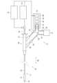
カテーテルシステム10は、例えば腎動脈91(図5(A)及び図5(B)参照)の神経に対してアブレーションを行うために用いられる。図1に示されるように、カテーテルシステム10は、アブレーションカテーテル11と、回路12と、駆動装置13と、レーザ光発生装置14と、回転装置15と、を具備する。なお、カテーテルシステム10は、心臓組織のアブレーションに用いられてもよい。[Catheter system 10]
The
[アブレーションカテーテル11]
図1、図2及び図3に示されるように、アブレーションカテーテル11は、先端側にバルーン21が設けられたシャフト22を有する。シャフト22は、軸線方向90に長尺な部材である。シャフト22は、軸線方向90に対して湾曲するように弾性的に撓む管体である。湾曲していない状態のシャフト22が延びる方向が、本明細書において軸線方向90と称される。なお、アブレーションカテーテル11は、不整脈に対するカテーテルアブレーション術(心筋焼灼術)に用いられてもよい。[Ablation Catheter 11]
1, 2, and 3, the
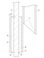
図2及び図3に示されるように、シャフト22の内部空間には、流体用チューブ23及び導光用チューブ51が位置する。シャフト22の外径及び内径は、軸線方向90に対して必ずしも一定である必要はない。シャフト22の素材は、合成樹脂やステンレスなどであり、また必ずしも1種類の素材のみから構成される必要はなく、複数の素材から構成されていてもよい。流体用チューブ23の内部空間が第1ルーメン24である。シャフト22の内部空間であって流体用チューブ23の外側の空間が第2ルーメン25である。As shown in Figures 2 and 3, the
なお、本実施形態において近位端側又は基端側とは、アブレーションカテーテル11が血管に挿入される向きに対して後ろ側(図1における右側)をいう。遠位端側とは、アブレーションカテーテル11が血管に挿入される向きに対して前側(図1における左側)をいう。In this embodiment, the proximal end side or base end side refers to the rear side (right side in FIG. 1) in the direction in which the
シャフト22の遠位端側には、バルーン21が設けられている。バルーン21は、内部空間に流体(液体)が流入されることにより弾性的に膨張し、内部空間から流体が流出されることにより収縮するものである。図1においては、収縮した状態のバルーン21が示されている。バルーン21に流通される流体は特に限定されないが、例えば、腎動脈91のアブレーションにおいては、生理食塩水と造影剤の混合溶液が用いられる。A
流体用チューブ23は、バルーン21を貫通している。流体用チューブ23は、遠位端部77がバルーン21より遠位端側へ突出する。流体用チューブ23は、バルーン21の内部空間に位置する開口71,72を有する。開口71,72は、流体用チューブ23の周壁をそれぞれ貫通している。開口71,72を通じて、第1ルーメン24がバルーン21の内部空間と連通している。開口71、72は、軸線方向90の周方向に対して異なる位置にある。なお、流体用チューブ23の遠位端部77は、流体用チューブ23のうち、バルーン21から突出しており、軸線方向90における遠位端側の一部であって、外周面及び端面を含む。流体用チューブ23は、シャフト22及びバルーン21の内部空間に挿通されて、バルーン21より遠位端側へ突出するチューブの一例である。The
シャフト22の内部空間である第2ルーメン25は、バルーン21の近位端側と接続されてバルーン21の内部空間と連通している。The
導光用チューブ51は、軸線方向90に対して湾曲するように弾性的に撓み得る管体である。導光用チューブ51の遠位端はバルーン21の内部空間へ至っており、基端はコネクタ部26を通じて外部へ延出されている。導光用チューブ51は、コネクタ部26に対して軸線方向90に沿って移動可能であり、かつ軸線方向90周りに回転可能である。The
導光用チューブ51の内部空間には光ファイバ52が位置する。すなわち、光ファイバ52は、シャフト22に挿通されている。光ファイバ52の遠位端の端面57は、軸線と直交している。光ファイバ52は、レーザ光発生装置14において発生されて、光ファイバ52の基端に照射されたレーザ光を遠位端側へ伝播する。光ファイバ52は、レーザ光の波長において全反射する屈折率を有するものが適宜採用される。An
導光用チューブ51の遠位端には、ハウジング53が取り付けられている。ハウジング53は、バルーン21の内部空間に位置する。ハウジング53は、管形状であり、その内部空間に光ファイバ52が位置する。ハウジング53は、周壁を貫通する開口54を有する。ハウジング53において開口54より遠位端側に反射材55が位置する。ハウジング53の内部空間において、光ファイバ52の端面57と反射材55とは離れており、光ファイバ52の端面57と反射材55との間に開口54が位置する。A
反射材55は、ハウジング53の内部空間において、光ファイバ52の端面57と軸線方向90に対向して位置する。反射材55は、バルーン21の内部空間において、光ファイバ52から出射されるレーザ光を反射する。反射されたレーザ光は、軸線方向90と直交する方向に出射される。反射材55において端面57と対向する反射面56は、軸線方向90に対して45度の角度となるように傾斜している。反射面56は、ハウジング53の開口54を通じてハウジング53の外部へ露出されている。反射材55は、金属や光ファイバ、樹脂等からなる円柱体である。反射材55の反射面56には、金属層が積層されている。金属層は、例えば、ニッケル、金、アルミニウム、クロム等が単独又は混合されて反射材55の表面にメッキ又はスパッタリング等により形成されたものである。なお、反射材55によって反射されたレーザ光が出射される方向は、軸線方向90と交差する方向であればよい。The
光ファイバ52及び反射材55は、端面57及び反射面56の位置関係、すなわち離間距離及び反射面56の角度を保持した状態で、導光用チューブ51と一体として軸線(軸線方向90)周りに回転可能であり、かつ軸線方向90へスライド可能である。光ファイバ52及び反射材55の回転及びスライドは、コネクタ部26から延出された導光用チューブ51の基端側が直接又は間接に操作されることによって制御される。具体的には、導光用チューブ51の基端側に回転装置15からの駆動力が付与されることによって、導光用チューブ51が回転及びスライドされる。The
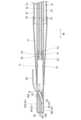
アブレーションカテーテル11は、バルーン21より遠位端側に設けられた先端部材61を有する。先端部材61には、ガイドワイヤルーメン62が形成されている。ガイドワイヤ80がガイドワイヤルーメン62に通されて、アブレーションカテーテル11がガイドワイヤ80に沿って患者の体内の所望の位置まで案内される。図5(B)に示されるように、所望の位置とは、例えば、腎動脈91の分岐92より腎臓側における腎動脈91内である。なお、アブレーションカテーテル11に設けられているガイドワイヤルーメンは、ガイドワイヤルーメン62のみである。The
図2、3に示されるように、先端部材61は、一部が流体用チューブ23の遠位端部77と繋がるカバーチューブ63と、カバーチューブ63の内部空間に位置する先端チップ64と、を有する。As shown in Figures 2 and 3, the
カバーチューブ63は、樹脂製である。カバーチューブ63は、近位端側の開口94と、遠位端側の開口95と、を有する。開口94、95は、カバーチューブ63の内部空間と外部空間とを連通する。開口94は、溶着の際にカバーチューブ63が曲げられて軸線方向90と交差する方向に向く。開口95は、軸線方向90の方向に向く。The
カバーチューブ63の近位端側の外周面は、遠位端部77の外周面又は内周面と溶着されている。遠位端部77は、先端部材61との溶着の際、外周面及び内周面を含む遠位端部77の開口周縁が先端部材61の外周面と溶着する。遠位端部77は、例えば内部空間が潰れて内周面同士が溶着することにより、液密に塞がれている。なお、遠位端部77は、先端部材61の外周面と遠位端部77の内周面が溶着することにより、液密に塞がれていてもよい。The outer peripheral surface of the proximal end side of the
カバーチューブ63は、先端チップ64を囲っている。カバーチューブ63は、内周面が管状の先端チップ64の外周面と溶着されている。カバーチューブ63の遠位端は、軸線方向90における位置が先端チップ64の遠位端と同じである。カバーチューブ63の硬度は、例えば、流体用チューブ23の硬度より小さい。The
先端チップ64は、造影される素材を含有する樹脂製である。樹脂としては、例えば、ポリウレタンなどが挙げられ、造影される素材としては、例えば、硫酸バリウム、酸化ビスマス、次炭酸ビスマスなどが挙げられる。先端チップ64の硬度は、カバーチューブ63の硬度より小さい。The
先端チップ64は、管状に形成され、内部空間がガイドワイヤルーメン62を区画する。先端チップ64は、近位端側の開口67を有する。先端チップ64の内部空間は、開口67を介して外部空間と連通する。開口67は、カバーチューブ63の近位端側の開口の内側に位置する。開口67は、ガイドワイヤルーメン62の近位端側の開口である。開口67は、溶着時に先端チップ64及びカバーチューブ63が変形することによって軸線方向90と交差する方向に向く。The
先端チップ64は、遠位端に開口68を有する。開口68は、先端チップ64の内部空間と外部空間とを連通する。開口68は、軸線方向90の方向に向く。すなわち、開口68は、先端部材61の遠位端面に開口する。ガイドワイヤルーメン62は、開口67及び開口68により、先端部材61の遠位端69及び近位端部70において開口することとなる。先端部材61の遠位端69は、軸線方向90の方向に向く先端部材61の遠位端側の端面を指す。先端部材61の近位端部70は、先端部材61のうち、軸線方向90における中央より近位端側の一部であって、外周面及び端面を含む。The
なお、図2、3に示される遠位端部77、カバーチューブ63及び先端チップ64は、溶着後の形状の一例であり、遠位端部77、カバーチューブ63及び先端チップ64の境界が示されたものである。遠位端部77と、カバーチューブ63と、先端チップ64とは、溶着により一体とされて、これらの境界が無い又は曖昧となっていてもよい。また、遠位端部77、カバーチューブ63及び先端チップ64が一部混ざり合ってもよい。したがって、遠位端部77、カバーチューブ63及び先端チップ64は、図2、3に示される構成でなくてもよく、それぞれの境界が曖昧な一体のものとして形成されていてもよい。The
図1に示されるように、シャフト22の基端側にはコネクタ部26が設けられている。コネクタ部26は、アブレーションカテーテル11を操作するときに施術者が持つ部分である。コネクタ部26には、光ファイバ52が挿通されている。コネクタ部26には、光ファイバ52の挿通口とは別個に第1ポート27及び第2ポート28が設けられている。As shown in FIG. 1, a
図4に示されるように、第1ポート27は、第1ルーメン24と連続している。第1ポート27を通じて、バルーン21に還流される流体が第1ルーメン24へ流入する。第2ポート28は、第2ルーメン25と連続している。第2ポート28を通じて、バルーン21に還流される流体が第2ルーメン25から流出する。なお、コネクタ部26の内部において、第1ポート27及び第2ポート28は、それぞれがOリング73、74によって液密に分離されている。また、導光用チューブ51の周囲は、Oリング75によって液密が確保されている。As shown in FIG. 4, the
[回路12]
回路12は、アブレーションカテーテル11に流体を流通させるために用いられる。図1に示されるように、回路12は、バッファタンク31と、第1流路32と、圧力センサ33と、第2流路34と、第2流路34に設けられている逆止弁35と、を有する。[Circuit 12]
The
バッファタンク31は、アブレーションカテーテル11及び回路12に流通させる流体を貯留する。バッファタンク31は、例えば、可撓性を有するバッグである。各図には現れていないが、バッファタンク31には、第1流路32及び第2流路34が接続されるポートを有する。The
第1流路32は、可撓性の合成樹脂チューブ36から構成される。第1流路32は、1本の合成樹脂チューブから構成されていてもよいし、複数本の合成樹脂チューブがジョイントなどによって継がれて構成されていてもよい。第1流路32は、バッファタンク31と第1ポート27とを流体が流通可能に接続する。The
第2流路34は、可撓性の合成樹脂チューブ37から構成される。第2流路34は、1本の合成樹脂チューブから構成されていてもよいし、複数本の合成樹脂チューブがジョイントなどによって継がれて構成されていてもよい。第2流路34は、バッファタンク31と第2ポート28とを流体が流通可能に接続する。なお、各流路と各ポートとの接続には公知のジョイントが用いられてよい。The
第1流路32における第1ポート27とポンプ41との間には、圧力センサ33が設けられている。圧力センサ33は、第1流路32における流体の圧力を検知して、検知した圧力に応じた検知信号を出力する。圧力センサ33としては、例えば、ダイアフラム式の圧力センサが用いられる。圧力センサ33の検知信号は、コントローラ44へ出力される。A
第2流路34には、逆止弁35が設けられている。逆止弁35は、ハウジング内に設けられた弁が流体の背圧によって移動することによって、一方向へ流体を流通させ、他方向への流体の流れを制止する。逆止弁35は、第2流路34において、流体が第2ポート28からバッファタンク31へ向かう方向を一方向として流体を流通させる。他方、逆止弁35は、第2流路34において、流体がバッファタンク31から第2ポート28へ向かう流れを制止する。A
[駆動装置13]
駆動装置13は、ポンプ41と、ディスプレイ42と、入力I/F43と、コントローラ44と、を有する。ポンプ41は、ローラーポンプであることが好ましい。ポンプ41には、第1流路32を構成する合成樹脂チューブ36がセットされる。ポンプ41は、双方向に駆動可能である。[Drive device 13]
The driving
ディスプレイ42としては、例えば、液晶ディスプレイ(Liquid Crystal Displayの略)、有機ELディスプレイ(Organic Electro-Luminescence Displayの略)等が採用される。Examples of the
入力I/F43は、ユーザによる入力操作を受け付けるユーザインタフェースである。具体的には、入力I/F43は、ディスプレイ42に重畳された膜状のタッチセンサである。また、入力I/F43は駆動装置13が備えるボタンであってもよい。入力I/F43は、ユーザ操作を受け付けて、受け付けた操作に応じた各種信号をコントローラ44へ出力する。操作信号としては、例えば、バルーン21の膨張、バルーン21の収縮等である。The input I/
コントローラ44は、不図示のメモリ、CPU等を有する。コントローラ44には、予めプログラムが設定されており、プログラムに従って、ポンプ41の動作、レーザ光発生装置14の動作、及び回転装置15の動作を制御する。The
[レーザ光発生装置14]
レーザ光発生装置14は、例えば、励起源の光がレーザ媒質に与えられ、光共振器の反射により発信されて出力するものである。レーザ光発生装置14から出力されるレーザ光は、連続波であることが好ましく、また、レーザ光の波長としては400~2000nmの範囲であることが好ましい。レーザ光発生装置14は、光ファイバ52の基端と接続されており、レーザ光発生装置14から出力されたレーザ光は光ファイバ52の基端面に照射される。[Laser light generating device 14]
The laser
[回転装置15]
回転装置15は、導光用チューブ51の基端側を軸線方向90に対して回転及びスライドさせる駆動力を付与するものであり、モータやスライダ等を組み合わせた機構が採用され得る。なお、回転装置15は必須ではなく、導光用チューブ51の基端側を施術者がハンドリングすることにより、導光用チューブ51が軸線方向90に対して回転及びスライドされてもよい。[Rotation device 15]
The
[アブレーションカテーテル11の使用方法]
以下、カテーテルシステム10におけるアブレーションカテーテル11の使用方法の一例を示す。図5(A)に示されるように、ガイドワイヤ80は、腎動脈91における分岐92より腎臓側の腎動脈91内の所定位置まで送られる。アブレーションカテーテル11は、体外においてガイドワイヤ80がガイドワイヤルーメン62に挿通される。そして、アブレーションカテーテルは、ガイドワイヤ80に沿って体内の腎動脈91内の所定位置まで送られる。[Method of using the ablation catheter 11]
An example of a method of using the
図5(B)に示されるように、アブレーションカテーテル11が所定位置まで送られた後、ガイドワイヤ80は、アブレーションカテーテル11から脱抜される。ガイドワイヤ80がアブレーションカテーテル11から脱抜された後、バルーン21が膨張され、レーザ照射操作が実行される。なお、レーザ照射操作では、回転装置15が導光用チューブ51及びハウジング53内の反射材55を回転させることで、シャフト22の軸線周りの全周方向へレーザを照射することができる。レーザ照射後、バルーン21は収縮され、アブレーションカテーテル11は、回収される。As shown in FIG. 5(B), after the
[アブレーションカテーテル11の製造方法]
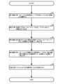
図6に示されるように、アブレーションカテーテル11の製造方法は、第1溶着工程(S1)と、組立工程(S2)と、第2溶着工程(S3)と、第3溶着工程(S4)と、引抜工程(S5)と、を有する。[Method of manufacturing ablation catheter 11]
As shown in FIG. 6, the method for manufacturing the
[第1溶着工程]
第1溶着工程では、バルーン21を流体用チューブ23及びシャフト22に加熱により溶着する。バルーン21の遠位端側の内周面は、シャフト22に挿通されシャフト22から突出する流体用チューブ23の外周面に溶着され、バルーン21の近位端側の内周面は、シャフト22の遠位端の外周面に溶着される。[First welding process]
In the first welding step, the
[組立工程]
図7に示されるように、組立工程では、先端チップ64と、カバーチューブ63と、マンドレル81と、が組み立てられる。[Assembly process]
As shown in FIG. 7, in the assembly process, the
マンドレル81は、溶着の際に先端チップ64の内部空間及び、近位端側の開口67と遠位端側の開口68とが繋がった状態を維持する。マンドレル81は、例えば、縦断面が円形状の金属製の棒材である。The
マンドレル81が先端チップ64の内部空間に挿通される。先端チップ64が、カバーチューブ63に挿入される。The
マンドレル81は、先端が先端チップ64の開口68から突出し、基端が先端チップ64の開口67から突出する。なお、マンドレル81が先端チップ64に挿通されるタイミングは、先端チップ64がカバーチューブ63に挿入された後であってもよい。The
先端チップ64の遠位端は、軸線方向90における位置がカバーチューブ63の遠位端と同じ位置である。The distal end of the
[第2溶着工程]
第2溶着工程では、組み立てられた管状の先端チップ64と、カバーチューブ63と、を加熱により溶着して一体とする工程である。第2溶着工程では、カバーチューブ63が、外側からヒーター(不図示)により加熱される。加熱されたカバーチューブ63は、内周面が先端チップ64の外周面と溶着する。溶着後のカバーチューブ63は、近位端部70の一部を構成する。[Second welding process]
In the second welding step, the assembled tubular
[第3溶着工程]
第3溶着工程では、バルーン21が溶着された流体用チューブ23と、第2溶着工程で溶着された先端部材61と、を加熱により溶着して一体とする工程である。流体用チューブ23の遠位端部77は、端面が軸線に対して直交しないように予め笹切りされている。図8に示されるように、遠位端部77は、バルーン21から突出する方向がマンドレル81の連続する方向に沿わされて、先端部材61に添えられる。このとき、遠位端部77の外周面は、一部が先端部材61の外周面の一部と当接する。また、遠位端部77の端面は、先端部材61の外周面側に向けられる。[Third welding process]
In the third welding step, the
第3工程では、流体用チューブ23と先端部材61とが合わせられた状態において、遠位端部77が、外側からヒーター(不図示)により加熱される。加熱により熱が、遠位端部77、カバーチューブ63、先端チップ64の順に伝達する。遠位端部77は、加熱によって、外周面及び内周面を含む遠位端部77の開口周縁が先端部材61の外周面と溶着し、例えば遠位端部77の内部空間が潰れて遠位端部77の内周面同士が溶着することで、液密に塞がれる。なお、遠位端部77は、先端部材61の外周面と遠位端部77の内周面が溶着することで液密に塞がれてもよい。第2溶着工程及び第3溶着工程は、加熱工程の一例である。In the third step, with the
[引抜工程]
第3溶着工程の後、先端部材61は、自然冷却される。冷却後に、マンドレル81は、先端部材61から引き抜かれる。マンドレル81によって保持された空間がガイドワイヤルーメン62となる。[Pulling process]
After the third welding step, the
[本実施形態の作用効果]
本実施形態では、バルーン21よりも遠位端側に設けられた先端部材61に形成されたガイドワイヤルーメン62にガイドワイヤ80が挿通されるので、先端部材61がガイドワイヤ80に追従し、バルーンを腎動脈へ容易に導くことができる。[Effects of this embodiment]
In this embodiment, the
また、バルーン21内にガイドワイヤルーメン62を区画する部材がないので、レーザ光が影響を受けることはなく、精度良くアブレーションを行うことができる。In addition, since there is no material that divides the
また、先端部材61のみにガイドワイヤルーメン62が形成されているため、ガイドワイヤ80をアブレーションカテーテル11の先端部材61に形成されたガイドワイヤルーメン62から抜くことのみによって、アブレーションカテーテル11からガイドワイヤ80を離すことができる。また、バルーンより近位端側のシャフトの外径を小さくすることができるとともに、シャフトを柔軟にすることができる。In addition, since the
また、シャフト22及びバルーン21の内部空間にガイドワイヤルーメンが設けられないため、光ファイバ52をシャフト22又はバルーン21の縦断面の径の中心に位置させることができる。これにより、出射されたレーザ光が血管まで到達するまでの距離を一定とすることができる。In addition, since no guidewire lumen is provided in the internal space of the
また、先端部材61は、流体用チューブ23より遠位端側に位置する先端チップ64と、先端チップ64と流体用チューブ23の遠位端とを接続するカバーチューブ63と、からなるため、先端部材61の構成が簡易となり、先端部材61が血管の湾曲などに追従しやすい。In addition, the
また、カバーチューブ63の硬度は、流体用チューブ23の硬度より小さく、先端チップ64の硬度より大きい。また、流体用チューブ23の遠位端部77の内周面の一部がカバーチューブ63の外周面の一部と溶着される。また、カバーチューブ63は、先端チップ64を囲っている。このように、流体用チューブ23と先端チップ64との硬度差を減らすことにより、先端チップ64が折れることが抑制されるほか、先端部材61の引張強度が向上する。The hardness of the
また、本実施形態のアブレーションカテーテル11の製造方法によれば、先端部材61にガイドワイヤルーメン62が形成されたアブレーションカテーテル11を簡易に製造することができる。In addition, according to the manufacturing method of the
また、第3溶着工程において、遠位端部77が先端部材61の外側にあり、加熱による熱が遠位端部77、カバーチューブ63、先端チップ64の順に伝達するため、作業者は、遠位端部77と先端部材61との溶着を目視により確認することができ、遠位端部77と先端部材61との溶着が完了しないうちに溶着の作業を終了することが抑制される。In addition, in the third welding process, the
また、第2溶着工程後ではなく、組立工程前にバルーン21を流体用チューブ23及びシャフト22に溶着することで、バルーン21がカバーチューブ63の外周面に溶着することが防がれ、バルーン21の遠位端側からの液漏れが防がれる。In addition, by welding the
また、流体用チューブ23は遠位端部77が笹切りされているため、第3溶着工程において、遠位端部77は、バルーン21から突出する方向がマンドレル81の連続する方向に沿わされた状態で、遠位端部77を先端部材61に添えて溶着することができる。これにより、筒状の先端部材61が延びる方向に対する遠位端部77がバルーン21から突出する方向の角度の調整が不要となり、溶着の作業性が良い。In addition, since the
また、シャフト22の直径を変更することなく、マンドレル81の直径を変更することで、ガイドワイヤルーメンの直径を容易に変更することができる。In addition, the diameter of the guidewire lumen can be easily changed by changing the diameter of the
[変形例1]
上記実施形態では、カバーチューブ63の遠位端の軸線方向90における位置が先端チップ64の遠位端と同じであった。これに代えて、カバーチューブ63の遠位端が、軸線方向90において、先端チップ64の遠位端より近位端側に位置していてもよい。[Modification 1]
In the above embodiment, the position of the distal end of the
図9に示されるように、先端部材161は、一部が流体用チューブ23の遠位端部77を塞ぐカバーチューブ163と、カバーチューブ163の内部空間に基端が位置する先端チップ64と、を有する。カバーチューブ163は、樹脂製である。カバーチューブ163の硬度は、例えば、先端チップ64の硬度より大きい。As shown in FIG. 9, the
カバーチューブ163は、近位端側の開口194と、遠位端側の開口195と、を有する。開口194、195は、カバーチューブ163の内部空間と外部空間とを連通する。開口194は、溶着の際にカバーチューブ163が曲げられて軸線方向90と交差する方向に向く。開口195は、軸線方向90の方向に向く。The
カバーチューブ163は、外周面が流体用チューブ23の遠位端部77の内周面と溶着されている。カバーチューブ163は、先端チップ64の基端を囲っている。カバーチューブ163は、内周面が管状の先端チップ64の近位端部の外周面と溶着されている。カバーチューブ163の遠位端は、軸線方向90における位置が先端チップ64の遠位端より近位端側に位置し、先端チップ64の遠位端69がカバーチューブ163の遠位端から突出している。先端チップ64は、硬度がカバーチューブ163の硬度より小さい。先端チップ64の開口67は、カバーチューブ163の開口194の内側に位置する。先端チップ64の開口68は、軸線方向90における位置がカバーチューブ163の開口195より遠位端側に位置する。The outer circumferential surface of the
[変形例1の作用効果]
先端チップ64は、カバーチューブ163の遠位端よりも遠位端側へ突出しており、先端チップ64の硬度は、カバーチューブ163の硬度より小さいため、先端部材61が血管の湾曲などに追従しやすい。また、先端部材61が血管を傷つけにくい。また、先端チップ64は、カバーチューブ163より外径が小さいため、アブレーションカテーテルの先端を小径化できる。[Effects of Modification 1]
The
[変形例2]
上記実施形態では、流体用チューブ23の遠位端部77は、第3溶着工程において先端部材61と溶着されたが、第2溶着工程において先端部材61と溶着されてもよい。変形例2では、流体用チューブ23の遠位端部77は、第2溶着工程においてカバーチューブ263及び先端チップ64と溶着され、第3溶着工程が省かれる例について説明される。なお、カバーチューブ63の代わりに、例えばカバーチューブ63より内径の大きいカバーチューブ263が用いられる。変形例の第2溶着工程は、加熱工程の一例である。[Modification 2]
In the above embodiment, the
変形例2のアブレーションカテーテルの製造方法では、第1溶着工程と、組み立て工程と、第2溶着工程と、引抜工程と、を有する。The manufacturing method for the ablation catheter of variant 2 includes a first welding process, an assembly process, a second welding process, and a withdrawal process.
[組立工程]
図10に示されるように、組立工程では、バルーン21が溶着された流体用チューブ23と、先端チップ64と、カバーチューブ263と、マンドレル81と、が組み立てられる。カバーチューブ263の近位端は、予めフレア加工が施されている。フレア加工は、公知の方法によって行われる。カバーチューブ263は近位端がフレア加工されているため、流体用チューブ23及び先端チップ64をカバーチューブ263に挿入する作業性が良い。[Assembly process]
As shown in Fig. 10, in the assembly process, the
マンドレル81が先端チップ64の内部空間に挿通される。先端チップ64が、カバーチューブ263に挿入される。また、流体用チューブ23の遠位端部77が、カバーチューブ263に挿入される。The
マンドレル81は、先端が先端チップ64の開口68から突出し、基端が先端チップ64の開口67から突出する。なお、マンドレル81が先端チップ64に挿通されるタイミングは、先端チップ64及び流体用チューブ23の遠位端部77がカバーチューブ263に挿入された後であってもよい。The
先端チップ64の遠位端は、軸線方向90における位置がカバーチューブ263の遠位端と同じ位置である。なお、流体用チューブ23の遠位端部77の一部は、カバーチューブ263の内部空間において、先端チップ64の一部と軸線方向90における位置が重なることが好ましい。The distal end of the
[第2溶着工程]
第2溶着工程では、組み立てられた流体用チューブ23と、管状の先端チップ64と、カバーチューブ263と、を加熱により溶着して一体とする工程である。第2溶着工程では、カバーチューブ263が、外側からヒーター(不図示)により加熱される。加熱されたカバーチューブ263は、内周面が先端チップ64の外周面の一部、流体用チューブ23の遠位端部77の外周面の一部と溶着する。先端チップ64の外周面の一部は、加熱により、流体用チューブ23の遠位端部77の外周面の一部及び遠位端部77の内周面の一部と溶着する。[Second welding process]
In the second welding step, the assembled
流体用チューブ23の遠位端部77は、加熱によって溶着することで液密に塞がれる。遠位端部77は、カバーチューブ263との溶着の際、カバーチューブ263の内部空間が潰され、液密に塞がれる。The
[引抜工程]
第2溶着工程の後、先端部材61は、自然冷却される。冷却後に、マンドレル81は、先端部材61から引き抜かれる。マンドレル81によって保持された空間がガイドワイヤルーメン62となる。[Pulling process]
After the second welding step, the
なお、図11に示されるように、変形例2のアブレーションカテーテルの製造方法によれば、遠位端部77は、カバーチューブ263の近位端側の開口294の内側に位置する。カバーチューブ263は、近位端側において流体用チューブ23の遠位端部77を囲う。As shown in FIG. 11, according to the manufacturing method of the ablation catheter of the second modified example, the
[その他の変形例]
本実施形態では、シャフト22内に流体用チューブ23が挿通されているが、流体用チューブ23は必須ではない。つまり、バルーン21内に流体を流入させる流入ルーメンと、バルーン21内から流体を流出させる流出ルーメンとが区別されていなくてもよい。この場合、バルーン21の遠位端からシャフト22の先端が突出され、シャフト22の先端と先端チップ64とがカバーチューブ63により接続される。[Other Modifications]
In this embodiment, the
また、本実施形態では、先端チップ64の内部空間がガイドワイヤルーメン62を区画したが、当該内部空間が区画せずともよい。このとき、先端チップ64の外周面とカバーチューブ63の内周面とがガイドワイヤルーメン62を区画してもよい。In addition, in this embodiment, the internal space of the
また、カバーチューブ63は、複数のチューブが軸線方向に加熱溶着によって繋げられて形成されてもよい。このとき、例えば、カバーチューブ63は、近位端側のチューブと遠位端側のチューブの2本から形成される。カバーチューブ63は、対向する近位端側のチューブの端面と遠位端側のチューブの端面とが当接した状態で溶着され、これらチューブ同士の内部空間が連続させられて形成される。近位端側のチューブと遠位端側のチューブは、第2溶着工程以前において溶着される。遠位端側のチューブの硬度は、近位端側のチューブより小さいことが好ましい。これにより、先端部材61が血管の湾曲などに追従しやすい。また、先端部材61が血管を傷つけにくい。The
また、カバーチューブ63の遠位端は、軸線方向90における位置が先端チップ64より遠位端側であってもよい。The distal end of the
また、先端チップ64の近位端がカバーチューブ63の近位端より突出してもよい。The proximal end of the
また、本実施形態では、先端部材61にのみガイドワイヤルーメン62が形成されたが、バルーン21より近位端側にガイドワイヤルーメンが形成されてもよい。このとき、例えば、シャフト22の外側にシャフト22に沿って延びるガイドワイヤ用チューブが用いられ、当該ガイドワイヤ用チューブの内部空間がガイドワイヤルーメンとされてもよい。In addition, in this embodiment, the
また、本実施形態では、ハウジング53及び反射材55が用いられたが、これらは用いられずともよい。このとき、例えば、導光用チューブ51及び光ファイバ52の遠位端が曲げられ、光ファイバ52の遠位端の端面57が軸線と交差する方向と直交する向きとされてもよい。In addition, although the
また、第1溶着工程は、第2溶着工程又は第3溶着工程の後に実施されてもよい。The first welding step may also be performed after the second welding step or the third welding step.
また、組立工程において、流体用チューブ23の遠位端部77は、予め笹切りされずともよく、端面が軸線と直交する輪切りであってもよい。In addition, in the assembly process, the
11・・・アブレーションカテーテル
21・・・バルーン
22・・・シャフト
23・・・流体用チューブ
52・・・光ファイバ
55・・・反射材
61,161・・・先端部材
62・・・ガイドワイヤルーメン
63,263・・・カバーチューブ
64・・・先端チップ
67・・・開口
68・・・開口
81・・・マンドレル
69・・・遠位端
70・・・近位端部
90・・・軸線方向
294・・・開口11: ablation catheter 21: balloon 22: shaft 23: fluid tube 52: optical fiber 55:
Claims (6)
Translated fromJapanese上記シャフトの遠位端側に設けられたバルーンと、
上記シャフトに挿通され、レーザ光を伝播して外部へ出射する光ファイバと、
上記バルーンより遠位端側に設けられた先端部材と、
上記シャフト及び上記バルーンに挿通されて、上記バルーンの遠位端より遠位端側へ突出するチューブと、を具備しており、
上記先端部材は、
上記先端部材の遠位端と近位端部とに開口するガイドワイヤルーメンと、
上記チューブより遠位端側に位置する先端チップと、
上記先端チップと上記チューブの遠位端部とを接続するカバーチューブと、を有しており、
上記ガイドワイヤルーメンは、少なくとも一部が上記先端チップにより区画されているアブレーションカテーテル。 A hollow shaft;
A balloon provided on the distal end side of the shaft;
an optical fiber that is inserted into the shaft and propagates the laser light and emits it to the outside;
A tip member provided on the distal end side of the balloon;
a tube that is inserted through the shaft and the balloon and protrudes beyond the distal end of the balloon ,
The tip member is
a guidewire lumen opening at the distal end and the proximal end of the tip member;
A tip located on the distal end side of the tube;
a cover tube connecting the tip and a distal end of the tube;
An ablation catheter, wherein the guidewire lumen is at least partially defined by the distal tip .
上記ガイドワイヤルーメンは、上記カバーチューブの近位端において開口する請求項1又は2に記載のアブレーションカテーテル。thetube opens into the balloon,
The ablation catheter according to claim 1 or 2,wherein the guidewire lumen opens at a proximal end of the cover tube.
上記先端チップの硬度は、上記カバーチューブの硬度より小さい請求項3に記載のアブレーションカテーテル。 The tip protrudes distally beyond the distal end of the cover tube,
4. The ablation catheter according to claim 3, wherein the hardness of the distal tip is less than the hardness of the cover tube.
加熱により、バルーンに挿通されたチューブの遠位端部、上記先端チップ、及び上記カバーチューブを一体とする加熱工程と、
一体となった上記チューブ、上記先端チップ、及び上記カバーチューブから上記マンドレルを引き抜く引抜工程と、を含むアブレーションカテーテルの製造方法。 an assembly process in which the distal tip through which the rod-shaped mandrel is inserted is covered with a cover tube so that the base end of the mandrel protrudes from the proximal end of the cover tube;
a heating step of integrating the distal end of the tube inserted into the balloon, the tip, and the cover tube by heating;
and a pulling step of pulling the mandrel out from the integrated tube, the distal tip, and the cover tube.
Priority Applications (1)
| Application Number | Priority Date | Filing Date | Title |
|---|---|---|---|
| JP2020138052AJP7608748B2 (en) | 2020-08-18 | 2020-08-18 | Ablation catheter and method for manufacturing the same |
Applications Claiming Priority (1)
| Application Number | Priority Date | Filing Date | Title |
|---|---|---|---|
| JP2020138052AJP7608748B2 (en) | 2020-08-18 | 2020-08-18 | Ablation catheter and method for manufacturing the same |
Publications (2)
| Publication Number | Publication Date |
|---|---|
| JP2022034313A JP2022034313A (en) | 2022-03-03 |
| JP7608748B2true JP7608748B2 (en) | 2025-01-07 |
Family
ID=80442233
Family Applications (1)
| Application Number | Title | Priority Date | Filing Date |
|---|---|---|---|
| JP2020138052AActiveJP7608748B2 (en) | 2020-08-18 | 2020-08-18 | Ablation catheter and method for manufacturing the same |
Country Status (1)
| Country | Link |
|---|---|
| JP (1) | JP7608748B2 (en) |
Citations (5)
| Publication number | Priority date | Publication date | Assignee | Title |
|---|---|---|---|---|
| WO1994003229A1 (en) | 1992-07-31 | 1994-02-17 | Scimed Life Systems, Inc. | Catheter with distal tip guide wire lumen |
| US5456680A (en) | 1993-09-14 | 1995-10-10 | Spectranetics Corp | Fiber optic catheter with shortened guide wire lumen |
| US5667521A (en) | 1992-11-12 | 1997-09-16 | Medtronic, Inc. | Rapid exchange catheter |
| JP2001503301A (en) | 1996-11-08 | 2001-03-13 | フォガティー,トマス・ジェイ | Transvascular TMR device and method |
| WO2018181315A1 (en) | 2017-03-31 | 2018-10-04 | テルモ株式会社 | Balloon catheter and method for manufacturing medical elongated body |
Family Cites Families (1)
| Publication number | Priority date | Publication date | Assignee | Title |
|---|---|---|---|---|
| JP4940583B2 (en)* | 2005-06-29 | 2012-05-30 | 株式会社カネカ | catheter |
- 2020
- 2020-08-18JPJP2020138052Apatent/JP7608748B2/enactiveActive
Patent Citations (5)
| Publication number | Priority date | Publication date | Assignee | Title |
|---|---|---|---|---|
| WO1994003229A1 (en) | 1992-07-31 | 1994-02-17 | Scimed Life Systems, Inc. | Catheter with distal tip guide wire lumen |
| US5667521A (en) | 1992-11-12 | 1997-09-16 | Medtronic, Inc. | Rapid exchange catheter |
| US5456680A (en) | 1993-09-14 | 1995-10-10 | Spectranetics Corp | Fiber optic catheter with shortened guide wire lumen |
| JP2001503301A (en) | 1996-11-08 | 2001-03-13 | フォガティー,トマス・ジェイ | Transvascular TMR device and method |
| WO2018181315A1 (en) | 2017-03-31 | 2018-10-04 | テルモ株式会社 | Balloon catheter and method for manufacturing medical elongated body |
Also Published As
| Publication number | Publication date |
|---|---|
| JP2022034313A (en) | 2022-03-03 |
Similar Documents
| Publication | Publication Date | Title |
|---|---|---|
| CN110420057B (en) | Ablation system and ablation device | |
| CN105636540B (en) | Ablation system and ablation equipment | |
| JP7254773B2 (en) | Imaging device | |
| JP6439274B2 (en) | Ablation device and ablation system | |
| US20090270850A1 (en) | Devices and methods for the ablation of tissue in the lateral direction | |
| CN114040702A (en) | Imaging probe with fluid pressurizing element | |
| US8359086B2 (en) | Device for applying and monitoring medical atherectomy | |
| JP2004097286A (en) | Catheter | |
| JP5662846B2 (en) | catheter | |
| CN110809432A (en) | catheter for imaging diagnosis | |
| CN111298271B (en) | Catheter tube | |
| JP7608748B2 (en) | Ablation catheter and method for manufacturing the same | |
| EP4147744A1 (en) | Catheter system, catheter equipped with circuit, circuit, and fluid circulation method | |
| JP2001245886A (en) | Ultrasonic echo catheter within blood vessel | |
| JP6354323B2 (en) | Ablation system and ablation device | |
| JP6354324B2 (en) | catheter | |
| US20230062912A1 (en) | Catheter system, catheter with circuit, circuit, and fluid circulation method | |
| US20240206971A1 (en) | Ablation catheter | |
| JP2000189517A (en) | Ultrasonic catheter | |
| JP4614265B2 (en) | In vivo observation catheter | |
| JP2003210462A (en) | Ultrasonic catheter | |
| JP6779799B2 (en) | Medical device | |
| JP3597066B2 (en) | Ultrasound catheter | |
| JP2024172739A (en) | Catheters and medical devices |
Legal Events
| Date | Code | Title | Description |
|---|---|---|---|
| A621 | Written request for application examination | Free format text:JAPANESE INTERMEDIATE CODE: A621 Effective date:20230620 | |
| A977 | Report on retrieval | Free format text:JAPANESE INTERMEDIATE CODE: A971007 Effective date:20240627 | |
| A131 | Notification of reasons for refusal | Free format text:JAPANESE INTERMEDIATE CODE: A131 Effective date:20240702 | |
| A521 | Request for written amendment filed | Free format text:JAPANESE INTERMEDIATE CODE: A523 Effective date:20240809 | |
| TRDD | Decision of grant or rejection written | ||
| A01 | Written decision to grant a patent or to grant a registration (utility model) | Free format text:JAPANESE INTERMEDIATE CODE: A01 Effective date:20241119 | |
| A61 | First payment of annual fees (during grant procedure) | Free format text:JAPANESE INTERMEDIATE CODE: A61 Effective date:20241202 | |
| R150 | Certificate of patent or registration of utility model | Ref document number:7608748 Country of ref document:JP Free format text:JAPANESE INTERMEDIATE CODE: R150 |