JP7608094B2 - MOBILE BODY, CONTROL DEVICE, MONITORING DEVICE, CONTROL METHOD, AND PROGRAM - Google Patents
MOBILE BODY, CONTROL DEVICE, MONITORING DEVICE, CONTROL METHOD, AND PROGRAMDownload PDFInfo
- Publication number
- JP7608094B2 JP7608094B2JP2020153266AJP2020153266AJP7608094B2JP 7608094 B2JP7608094 B2JP 7608094B2JP 2020153266 AJP2020153266 AJP 2020153266AJP 2020153266 AJP2020153266 AJP 2020153266AJP 7608094 B2JP7608094 B2JP 7608094B2
- Authority
- JP
- Japan
- Prior art keywords
- speed
- moving
- detection unit
- control
- movement
- Prior art date
- Legal status (The legal status is an assumption and is not a legal conclusion. Google has not performed a legal analysis and makes no representation as to the accuracy of the status listed.)
- Active
Links
Images


Classifications
- B—PERFORMING OPERATIONS; TRANSPORTING
- B62—LAND VEHICLES FOR TRAVELLING OTHERWISE THAN ON RAILS
- B62D—MOTOR VEHICLES; TRAILERS
- B62D63/00—Motor vehicles or trailers not otherwise provided for
- B62D63/02—Motor vehicles
- G—PHYSICS
- G05—CONTROLLING; REGULATING
- G05D—SYSTEMS FOR CONTROLLING OR REGULATING NON-ELECTRIC VARIABLES
- G05D1/00—Control of position, course, altitude or attitude of land, water, air or space vehicles, e.g. using automatic pilots
- G05D1/02—Control of position or course in two dimensions
- G05D1/021—Control of position or course in two dimensions specially adapted to land vehicles
- G05D1/0268—Control of position or course in two dimensions specially adapted to land vehicles using internal positioning means
- G05D1/0272—Control of position or course in two dimensions specially adapted to land vehicles using internal positioning means comprising means for registering the travel distance, e.g. revolutions of wheels
- B—PERFORMING OPERATIONS; TRANSPORTING
- B60—VEHICLES IN GENERAL
- B60W—CONJOINT CONTROL OF VEHICLE SUB-UNITS OF DIFFERENT TYPE OR DIFFERENT FUNCTION; CONTROL SYSTEMS SPECIALLY ADAPTED FOR HYBRID VEHICLES; ROAD VEHICLE DRIVE CONTROL SYSTEMS FOR PURPOSES NOT RELATED TO THE CONTROL OF A PARTICULAR SUB-UNIT
- B60W30/00—Purposes of road vehicle drive control systems not related to the control of a particular sub-unit, e.g. of systems using conjoint control of vehicle sub-units
- B60W30/14—Adaptive cruise control
- B60W30/143—Speed control
- B60W30/146—Speed limiting
- B—PERFORMING OPERATIONS; TRANSPORTING
- B60—VEHICLES IN GENERAL
- B60B—VEHICLE WHEELS; CASTORS; AXLES FOR WHEELS OR CASTORS; INCREASING WHEEL ADHESION
- B60B19/00—Wheels not otherwise provided for or having characteristics specified in one of the subgroups of this group
- B60B19/003—Multidirectional wheels
- B—PERFORMING OPERATIONS; TRANSPORTING
- B60—VEHICLES IN GENERAL
- B60K—ARRANGEMENT OR MOUNTING OF PROPULSION UNITS OR OF TRANSMISSIONS IN VEHICLES; ARRANGEMENT OR MOUNTING OF PLURAL DIVERSE PRIME-MOVERS IN VEHICLES; AUXILIARY DRIVES FOR VEHICLES; INSTRUMENTATION OR DASHBOARDS FOR VEHICLES; ARRANGEMENTS IN CONNECTION WITH COOLING, AIR INTAKE, GAS EXHAUST OR FUEL SUPPLY OF PROPULSION UNITS IN VEHICLES
- B60K7/00—Disposition of motor in, or adjacent to, traction wheel
- B60K7/0007—Disposition of motor in, or adjacent to, traction wheel the motor being electric
- G—PHYSICS
- G05—CONTROLLING; REGULATING
- G05D—SYSTEMS FOR CONTROLLING OR REGULATING NON-ELECTRIC VARIABLES
- G05D1/00—Control of position, course, altitude or attitude of land, water, air or space vehicles, e.g. using automatic pilots
- G05D1/02—Control of position or course in two dimensions
- G05D1/021—Control of position or course in two dimensions specially adapted to land vehicles
- G05D1/0212—Control of position or course in two dimensions specially adapted to land vehicles with means for defining a desired trajectory
- G05D1/0214—Control of position or course in two dimensions specially adapted to land vehicles with means for defining a desired trajectory in accordance with safety or protection criteria, e.g. avoiding hazardous areas
- G—PHYSICS
- G05—CONTROLLING; REGULATING
- G05D—SYSTEMS FOR CONTROLLING OR REGULATING NON-ELECTRIC VARIABLES
- G05D1/00—Control of position, course, altitude or attitude of land, water, air or space vehicles, e.g. using automatic pilots
- G05D1/02—Control of position or course in two dimensions
- G05D1/021—Control of position or course in two dimensions specially adapted to land vehicles
- G05D1/0212—Control of position or course in two dimensions specially adapted to land vehicles with means for defining a desired trajectory
- G05D1/0223—Control of position or course in two dimensions specially adapted to land vehicles with means for defining a desired trajectory involving speed control of the vehicle
- G—PHYSICS
- G05—CONTROLLING; REGULATING
- G05D—SYSTEMS FOR CONTROLLING OR REGULATING NON-ELECTRIC VARIABLES
- G05D1/00—Control of position, course, altitude or attitude of land, water, air or space vehicles, e.g. using automatic pilots
- G05D1/02—Control of position or course in two dimensions
- G05D1/021—Control of position or course in two dimensions specially adapted to land vehicles
- G05D1/0231—Control of position or course in two dimensions specially adapted to land vehicles using optical position detecting means
- G05D1/0238—Control of position or course in two dimensions specially adapted to land vehicles using optical position detecting means using obstacle or wall sensors
- G05D1/024—Control of position or course in two dimensions specially adapted to land vehicles using optical position detecting means using obstacle or wall sensors in combination with a laser
Landscapes
- Engineering & Computer Science (AREA)
- Physics & Mathematics (AREA)
- Automation & Control Theory (AREA)
- Aviation & Aerospace Engineering (AREA)
- Radar, Positioning & Navigation (AREA)
- Remote Sensing (AREA)
- General Physics & Mathematics (AREA)
- Mechanical Engineering (AREA)
- Transportation (AREA)
- Chemical & Material Sciences (AREA)
- Combustion & Propulsion (AREA)
- Electromagnetism (AREA)
- Optics & Photonics (AREA)
- Control Of Position, Course, Altitude, Or Attitude Of Moving Bodies (AREA)
Description
Translated fromJapanese特許法第30条第2項適用 〔1〕▲1▼発行日(公知日) 令和2年5月27日 ▲2▼刊行物 ロボティクス・メカトロニクス講演会2020 in Kanazawa 予稿集 一般社団法人日本機械学会 ロボティクス・メカトロニクス部門 発行(Web公開URL:https://robomech.org/2020/ *参加者専用アドレスよりダウンロードにて発行・配布) <資 料> 講演会概要 ウェブページ プリントアウト <資 料> 予稿集掲載研究論文 抜粋 〔2〕▲1▼開催日(公開日) 令和2年5月28日(会期:2020年5月27日~30日) ▲2▼集会名 ロボティクス・メカトロニクス講演会2020 in Kanazawa 一般社団法人日本機械学会 ロボティクス・メカトロニクス部門 主催(オンライン開催:https://robomech.org/2020/ ) <資 料> 講演会スケジュール、及びプログラム <資 料> ポスターセッション研究発表資料Article 30,
本発明の実施形態は、移動体、制御装置、監視装置、制御方法、及びプログラムに関する。Embodiments of the present invention relate to a moving object, a control device, a monitoring device, a control method, and a program.
従来、物流倉庫内の荷物の搬送の省力化のために、自律移動(走行)するロボットや搬送車などの移動体が実用化されている。移動体の走行を制御する方式には、例えば、床面の誘導線に沿って走行するガイド方式と、移動体の周囲の環境を検出して自律的な制御を行うガイドレス方式とがある。また、移動体は、監視領域内の障害物を検出する非接触の障害物検出器や、障害物検出器による検出結果を用いて、移動体を停止させる制御部を備える。これにより、移動体の進行方向に障害物がある場合でも、障害物に衝突せずに停止させることが可能である。Conventionally, autonomously moving (traveling) mobile objects such as robots and transport vehicles have been put to practical use to reduce the labor required for transporting luggage in logistics warehouses. Methods for controlling the travel of mobile objects include, for example, a guided method in which the object travels along a guide line on the floor, and a guideless method in which the object detects the environment around the object and performs autonomous control. In addition, the mobile object is equipped with a non-contact obstacle detector that detects obstacles within a monitoring area, and a control unit that stops the mobile object using the detection results from the obstacle detector. This makes it possible to stop the mobile object without colliding with the obstacle, even if there is an obstacle in the moving direction of the mobile object.
また、近年では、3個以上の駆動輪を備え、全方向に移動可能な全方向移動機構を有する移動体が知られている。全方向移動機構に用いられる駆動輪には、例えば、メカナムホイールが用いられる。全方向に移動可能な移動体は、前進や、方向転換のほか、真横への移動や、その場での旋回など、複雑な動作を瞬時に行える。ここで、移動体には、人の保護を目的とした安全制御系を備えるものがある。安全制御系は、例えば、センサ等によって監視領域内の障害物が検出されると、移動体を低速にしたり、停止させたりする。In recent years, mobile objects have become known that have three or more drive wheels and an omnidirectional mechanism that allows them to move in all directions. Mecanum wheels, for example, are used as drive wheels for omnidirectional mechanisms. Mobile objects that can move in all directions can instantly perform complex movements such as moving forward, changing direction, moving sideways, and turning on the spot. Some mobile objects are equipped with a safety control system for the purpose of protecting people. For example, the safety control system slows down or stops the mobile object when an obstacle is detected in the monitoring area by a sensor or the like.
また、移動体は、監視領域内の物体を常に障害物として検出してしまうと、例えば、搬送対象物に近付いた際に停止してしまい、搬送対象物を搬送するという本来の目的を達成できない。そこで、移動体が所定速度以下で走行した場合には、搬送対象物の近くに移動したと見なして、監視領域を縮小させることにより、搬送対象物を障害物として検出しないようにすることが可能である。Furthermore, if the moving body constantly detects objects within the monitoring area as obstacles, it will stop, for example, when it approaches the object to be transported, and will not be able to achieve its original purpose of transporting the object. Therefore, when the moving body travels at or below a certain speed, it is assumed that it has moved close to the object to be transported, and the monitoring area can be reduced so that the object is not detected as an obstacle.
ここで、全方向に移動可能な移動体が所定速度以下であるか否かを判定するにあたり、移動体の速度制御に用いられる速度指令値を用いたとする。この場合、例えば、モータ制御系や移動体の慣性による時間の遅れや、信号処理の遅延や、エラーなどにより、速度指令値が示す速度と、実際の移動体の速度とが異なってしまうことがある。このため、実際には移動体の速度が所定速度以下ではないにもかかわらず、所定速度以下であると判定してしまうと、監視領域を縮小させてしまうことがある。したがって、適切に障害物を検出することができないことがある。また、監視領域を縮小させたままの状態で、移動体が高速で移動してしまうと、移動体を安全に停止させることができないことがある。このため、全方向に移動可能な移動体の安全を保障することができないおそれがあった。Here, suppose that a speed command value used for controlling the speed of a moving body that can move in all directions is used to determine whether the moving body is moving at or below a predetermined speed. In this case, for example, the speed indicated by the speed command value may differ from the actual speed of the moving body due to time delays caused by the motor control system or the inertia of the moving body, delays in signal processing, errors, etc. For this reason, if it is determined that the moving body is moving at or below the predetermined speed even though it is not actually moving at or below the predetermined speed, the monitoring area may be reduced. As a result, it may not be possible to properly detect an obstacle. Also, if the moving body moves at high speed while the monitoring area remains reduced, it may not be possible to safely stop the moving body. For this reason, there is a risk that the safety of a moving body that can move in all directions may not be guaranteed.
本発明が解決しようとする課題は、全方向に移動可能な移動体の安全性を向上させることができる、移動体、制御装置、監視装置、制御方法、及びプログラムを提供することである。The problem that the present invention aims to solve is to provide a moving body, a control device, a monitoring device, a control method, and a program that can improve the safety of a moving body that can move in all directions.
実施形態の移動体は、駆動輪と、回転速度検出部と、移動速度検出部と、物体検出部と、第1制御部と、第2制御部と、を持つ。駆動輪は、移動体に設けられ、それぞれが独立して駆動される3個以上の駆動輪である。回転速度検出部は、前記駆動輪のそれぞれの回転速度を検出する。移動速度検出部は、前記回転速度検出部によって検出されたそれぞれの回転速度を用いて、前記移動体の移動速度を検出する。物体検出部は、前記移動体の周囲に設定される監視領域内において、物体を検出する。第1制御部は、前記移動体を移動計画に応じて移動させる。第2制御部は、変更部と、停止部とを持つ。停止部は、前記移動速度検出部によって検出された前記移動速度が設定された速度閾値に達した場合に前記移動体を停止するように制御する。変更部は、前記第1制御部から出力される動作信号に基づいて前記監視領域の範囲を小さく又は無効化するように前記物体検出部を制御して、前記に応じて前記移動速度の速度閾値を下げるように設定する。 The moving body of the embodiment has a drive wheel, a rotation speed detection unit, a moving speed detection unit, an object detection unit,a first control unit, anda second control unit . The drive wheels are three or more drive wheels provided on the moving body and each of which is driven independently. The rotation speed detection unit detects the rotation speed of each of the drive wheels. The moving speed detection unit detects the moving speed of the moving body using each of the rotation speeds detected by the rotation speed detection unit. The object detection unit detects an object within a monitoring area set around the moving body.The first control unit moves the moving body according to a moving plan.The second control unit has a change unit and a stop unit. The stop unitcontrols the moving body to stop when the moving speed detected by the moving speed detection unit reaches aset speed threshold. The change unit controlsthe object detection unit to reduce or disable the range of the monitoring area based on an operation signal output from thefirst control unit, andsets the speed thresholdof the moving speed to be lowered according to the above.
以下、実施形態の移動体、制御装置、監視装置、制御方法、及びプログラムを、図面を参照して説明する。The mobile object, control device, monitoring device, control method, and program of the embodiment will be described below with reference to the drawings.
(第1の実施形態)
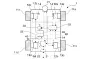
図1Aおよび図1Cは、第1の実施形態に係る全方向移動体1の全体構成の一例を示す図である。全方向移動体1は、全方向移動機構を備え、自律移動(走行)する搬送ロボットである。具体的には、全方向移動体1は、物流倉庫内における物流用のかご台車を搬送する。全方向移動体1は、駆動系と、制御系とを備える。(First embodiment)
1A and 1C are diagrams showing an example of the overall configuration of an omnidirectional
まず、駆動系について説明する。図1Aおよび図1Cに示すように、駆動系は、4個のメカナムホイール11a~11dと、4個の駆動モータ12a~12dと、4個の回転速度検出器13a~13dとを備える。なお、本明細書において、メカナムホイール11a~11dは、特に区別する必要がない場合には、単に「メカナムホイール11」と称する。同様に、駆動モータ12a~12dや回転速度検出器13a~13dについても、それぞれ単に「駆動モータ12」や「回転速度検出器13」と称する。First, the drive system will be described. As shown in Figures 1A and 1C, the drive system comprises four Mecanum
メカナムホイール11は、車輪円周上に設けられた樽がそれぞれ回転することにより、全方向移動体1の、前進、方向転換、真横への移動や、その場での旋回などを、準備動作なく瞬時に行うことを可能にする。なお、メカナムホイール11の詳細については、図2を用いて後述する。The Mecanum wheel 11 allows the
駆動モータ12は、トルクを発生させて、メカナムホイール11を駆動させる。駆動モータ12は、減速機の機能を含む。減速機は、駆動モータ12の回転を減速させ(トルクを増加させ)、メカナムホイール11に回転力を伝える。The
回転速度検出器13は、速度センサであり、メカナムホイール11の回転速度を検出し、回転量を電気信号に変換する。回転速度検出器13には、例えば、ロータリエンコーダが用いられる。また、各車輪の回転を止める制動機14が備えられていてもよい。制動機14は、駆動モータ12への通電を遮断すると制動力が作用するタイプのものを用いることが好適である。なお、図1Aのモータ制御回路23と、駆動モータ12とを繋ぐ矢印線は、モータ駆動用の配線と、制動機14を用いる場合の制動機14への通電配線を示している。The
次に、制御系について説明する。制御系は、外部通信機21と、主制御器22と、モータ制御回路23と、セーフティーレーザスキャナ31と、速度監視モジュール32と、遮断器33とを備える。外部通信機21は、ネットワークを介して、外部の通信装置との無線による通信を行う。外部通信機21は、物流倉庫内のすべての全方向移動体1を管理する外部のコンピューター装置から、所定のタイミングで全方向移動体1の移動計画を受信する。Next, the control system will be described. The control system comprises an
移動計画は、全方向移動体1の搬送に関する様々な情報を含む。具体的には、移動計画は、例えば、物流倉庫内における全方向移動体1の移動経路の情報や、低速走行するエリアの情報、搬送対象物であるかご台車を示す情報、搬送対象物の搬送先を示す情報などを含む。外部通信機21は、外部のコンピューター装置から受信した情報を主制御器22へ出力する。外部通信機21は、通信インターフェースである。なお、ネットワークは、例えば、インターネット、WAN(Wide Area Network)、LAN(Local Area Network)、セルラー網、Wi-Fi(登録商標)、Bluetooth(登録商標)、NFC(Near field communication)、赤外線通信などを含む。The movement plan includes various information related to the transportation of the omnidirectional
セーフティーレーザスキャナ31は、全方向移動体1の周囲の物体の存在を検出するセンサである。具体的には、セーフティーレーザスキャナは、赤外線レーザを走査し、反射してくる光の時間の遅れを測定することにより、周囲の物体までの距離や物体の形状を測定する。セーフティーレーザスキャナ31は、例えば、全方向移動体1の前方に取り付けられている。The
セーフティーレーザスキャナ31は、予め設定した領域(監視領域)に物体があるか否かの判定を行う。セーフティーレーザスキャナ31は、予め設定した領域に物体があると判定した場合、駆動モータ12等の機器を停止させるための停止信号を主制御器22へ出力する。The
ここで、セーフティーレーザスキャナの出力信号には、非安全信号と、安全信号とがある。非安全信号は、全方向移動体1の減速など、全方向移動体1を保護する目的で使用される。一方で安全信号は、電源遮断のためのリレーなど、危険事象の発生時に確実に全方向移動体1を止めるための信号として用いられる。非安全信号は、例えば、主制御器22へ出力される。安全信号は、例えば、遮断器33や主制御器22へ出力される。The output signals of the safety laser scanner include non-safety signals and safety signals. Non-safety signals are used for the purpose of protecting the omnidirectional
主制御器22は、全方向移動体1の移動計画を用いて、全方向移動体1の動作を切り替えるための動作信号をモータ制御回路23へ出力する。なお、主制御器22は、移動計画を、外部通信機21から無線によって取得することに限らず、操作者の操作入力によって取得してもよいし、外部の装置と有線で接続することによって取得してもよい。The
また、主制御器22は、セーフティーレーザスキャナ31によって監視領域内で物体が検出された場合は、全方向移動体1を減速させるための動作信号をモータ制御回路23へ出力する。In addition, if an object is detected within the monitoring area by the
モータ制御回路23は、主制御器22から出力された動作信号を用いて、駆動モータの回転を制御し、全方向移動体1を所定の速度で所定の方向に移動させたり、減速させたりする。全方向移動体1を停止させる手段としては、主制御器22からの回転数指令値に従う制御停止のほか、モータ制御回路23の電源を遮断した場合には、各駆動モータ12の駆動力が消失することによる惰性での回転停止や、モータ制御回路23および駆動モータ系の電気抵抗での回生電力散逸による制動トルクを利用することもできる。また、制動機14を備えるようにした場合には、モータ制御回路23から制動機14への通電を遮断させることで制動力が生じることになる。これにより、全方向移動体1を停止させることも可能である。The
ここで、図1Cに示すように、全方向移動体1を含む自律移動ロボットの制御系は、通常制御系Nrと、安全制御系Sfとの2つの制御系を含む。通常制御系Nrは、周囲の障害物等の状況を検出して、効率的に全方向移動体1を移動させるための制御系である。例えば、通常制御系Nrは、レーザスキャナ31bによって得られる距離データと、地図情報と、移動計画とから、全方向移動体1の動作を制御することである。図1Cでは、通常制御系Nrにレーザスキャナ31bの距離データを使用しているが、セーフティーレーザスキャナからの距離データ(非安全信号)を使用することもできる。また、通常制御系Nrは、例えば、レーザスキャナ31bもしくはセーフティーレーザスキャナ31からの非安全信号に含まれる、周囲の物体との距離データを用いて地図情報の作成も行う。また、通常制御系Nrは、移動計画や、操作者が操作するインターフェースとしての機能も有する。Here, as shown in FIG. 1C, the control system of the autonomous mobile robot including the omnidirectional
自律移動ロボットの制御系では、動作の不具合による事故の回避や、他の動作に優先すべき人との衝突の回避など、人を保護する目的として、十分な信頼性を確保する必要がある。通常制御系Nrの機能だけでは、このような信頼性を確保することは不十分であり、また、搬送の効率化と、搬送の安全性とを両立させることが困難な場合がある。The control system of an autonomous mobile robot must ensure sufficient reliability in order to protect people, such as by avoiding accidents caused by operational malfunctions and collisions with people that should take priority over other operations. Normally, the functions of the control system Nr alone are insufficient to ensure this reliability, and it can be difficult to achieve both efficient and safe transportation.
そこで、全方向移動体1の制御系は、通常制御系Nrとは別に、安全制御系Sfを備える。安全制御系Sfは、主に安全を確保するための制御系である。通常制御系Nr(主制御器22)は、安全制御系Sf(速度監視モジュール32)に、ミューティング信号等の動作信号Sgを送信する。安全制御系Sfは、動作信号を受信して、防護領域を無効にしたり、非常停止用速度閾値を変更したりする。The control system of the omnidirectional
ここで、仮に、安全制御系Sf(速度監視モジュール32)を介在させずに、主制御器22からの動作信号を用いて直接的にミューティング信号をセーフティーレーザスキャナに出力したとする。この場合、主制御器22がハングアップした際に動作信号(ミューティング信号)を出力していたとすると、ミューティング信号が出力され続けてしまい、セーフティーレーザスキャナの安全機能が一部停止した状態で走行を続けてしまうことがある。また、エラー等により、誤って非常停止用速度閾値等を変更してしまったり、誤って変更後の非常停止用速度閾値で非常停止させてしまったりするおそれがある。Let us now assume that a muting signal is output directly to the safety laser scanner using an operation signal from the
一方で、安全制御系Sf(速度監視モジュール32)は、誤動作のリスクが低く、また、故障もしにくい。仮に、故障したとしても、速度監視モジュール32は、モータ制御回路23に供給する電力を遮断させることができるため、安全な状態を保持させることができる。このように、速度監視モジュール32を介在させて、防護領域401の範囲および非常停止用速度閾値を変更させるようにすることにより、安全制御系Sfの信頼性を確保することができる。On the other hand, the safety control system Sf (speed monitoring module 32) has a low risk of malfunction and is unlikely to break down. Even if it does break down, the
安全制御系Sfは、セーフティーレーザスキャナ31によって周囲の状況を監視して、障害物などの物体の接近が検出された場合に、全方向移動体1を確実に停止させる。なお、図1Aにおいて、符号40は、安全信号を含む制御信号を示す。The safety control system Sf monitors the surroundings using a
例えば、セーフティーレーザスキャナ31は、防護領域内に物体を検出すると、遮断器33へ安全信号を出力する。また、速度監視モジュール32は、全方向移動体1の移動速度が非常停止用速度閾値(例えば、1.1m/s)に達すると、遮断器33へ安全信号を出力する。そして、遮断器33は、安全信号が入力されると、モータ制御回路23に供給する電力を遮断することにより、各メカナムホイール11の駆動を停止させる。停止は、駆動力消失により惰性で回転が停止することのほか、モータ制御回路23と駆動モータ系での電気抵抗(回生電力消費)による制動トルクの発生や、さらに制動機14を備えるようにした場合にはその制動力が利用されることによって停止することである。遮断器33は、例えば、ミラーコンタクタによって実現される。また、図1Cに図示していないが、モータ制御回路に外部信号入力による非常停止機能が備えられている場合、遮断器33に入力している安全信号をモータ制御回路に入力することで停止を実現することもできる。For example, when the
また、安全制御系Sfは、通常制御系Nrに異常が生じた場合でも、全方向移動体1を確実に停止させるために、長期間にわたって故障しない頑健性や、故障を検出する機能、故障した際に全方向移動体1を安全に停止させる機能などが求められる。In addition, the safety control system Sf is required to be robust enough not to break down for a long period of time, have the ability to detect failures, and have the ability to safely stop the omnidirectional
ここで、監視領域には、セーフティーレーザスキャナ31の中心から遠方に向かって、例えば、防護領域と、警告領域とが設定されている。セーフティーレーザスキャナ31は、監視領域の範囲を示す複数のパターンを記憶することが可能である。Here, in the monitoring area, for example, a protection area and a warning area are set from the center of the
速度監視モジュール32は、セーフティーレーザスキャナ31に設定されるパターンを切り替える。具体的には、速度監視モジュール32は、全方向移動体1が単体で走行する動作や、搬送対象物を搬送する動作や、搬送対象物をピックアップする動作など、それぞれの動作に応じて、パターン(警告領域や防護領域の範囲を示すパターン)を切り替える。The
ここで、安全制御系Sfの防護領域(非常停止機能)が常に機能すると、全方向移動体1の利便性を阻害し、本来の利用目的を達成できない場合がある。例えば、全方向移動体1が、搬送対象物をピックアップ(ドッキング)する場合に、安全制御系Sfが機能していると、搬送対象物を障害物として検出してしまい、全方向移動体1が停止してしまうことがある。すなわち、搬送対象物をピックアップすること(搬送対象物の下に潜り込むこと)ができず、搬送対象物を搬送するという本来の目的を達成することができないことがある。Here, if the protective area (emergency stop function) of the safety control system Sf is always functioning, it may impair the convenience of the omnidirectional
そこで、安全制御系Sfは、全方向移動体1が搬送対象物に接近する場合には、セーフティーレーザスキャナ31に設定される防護領域の範囲を一時的に小さく、または、防護領域の範囲を無効(ミューティング)にすると前記の利便性の阻害を防ぐことが出来ると考えられる。具体的には、全方向移動体1が所定速度以下となった場合に、速度監視モジュール32は、一時的に防護領域を小さく、または、無効にする。これにより、全方向移動体1は、搬送対象物をピックアップすることが可能になる。Therefore, it is believed that the safety control system Sf can prevent the above-mentioned inconvenience from being hindered by temporarily reducing the range of the protection area set in the
また、安全制御系Sfは、移動計画に基づく通常制御系Nrからの指令に基づいて、セーフティーレーザスキャナ31に設定される防護領域の範囲を一時的に小さく、または、無効にした場合、全方向移動体1を緊急停止させるための非常停止用速度閾値を変更する。具体的には、安全制御系Sfは、防護領域の範囲を、変更前の第1非常停止用速度閾値(例えば、1.1m/s)よりも低い第2非常停止用速度閾値(例えば、0.3m/s)に変更する。変更前後の各非常停止用速度閾値は、上記の値に限らず、安全基準や衝突時のリスクを考慮した任意の数値に設定することが可能である。Furthermore, when the range of the protection area set in the
なお、各機器間を伝達する信号には、定期的に故障を検出するための信号が含まれてもよい。また、信号を受信する機器は、故障を検出するための信号には反応しない時間的フィルタなどを備えていてもよい。また、図1Aにおいて、各機器間を伝達する信号線は、1本の線を示すが、一般的な安全制御系に用いられる信号の配線と同様に、2重化されていてもよい。また、各機器間の情報伝達には、産業用通信プロトコル(例えば、Ethernet/IP,PROFINET,EtherCAT,Profibus,Modbus,CC-Link,CANopenなど)、および、その安全対応の通信プロトコルを用いてもよい。The signals transmitted between the devices may include a signal for periodically detecting a fault. The device receiving the signal may be equipped with a time filter that does not react to the signal for detecting a fault. In FIG. 1A, the signal line transmitted between the devices is shown as a single line, but it may be duplicated like the signal wiring used in a general safety control system. In addition, industrial communication protocols (e.g., Ethernet/IP, PROFINET, EtherCAT, Profibus, Modbus, CC-Link, CANopen, etc.) and their safety-compatible communication protocols may be used to transmit information between the devices.
なお、主制御器22は、CPU(Central Processing Unit)などのハードウェアプロセッサがプログラム(ソフトウェア)を実行することにより実現される。また、モータ制御回路23および速度監視モジュール32は、それぞれハードウェア(回路部;circuitryを含む)によって実現される。The
ただし、モータ制御回路23、および速度監視モジュール32は、それぞれ、例えば、CPUなどのハードウェアプロセッサがプログラムを実行することにより実現されてもよい。また、主制御器22、モータ制御回路23、および速度監視モジュール32は、これらの構成要素のうち一部または全部は、LSI(Large Scale Integration)やASIC(Application Specific Integrated Circuit)、FPGA(Field-Programmable Gate Array)、GPU(Graphics Processing Unit)などのハードウェア(回路部;circuitryを含む)によって実現されてもよいし、ソフトウェアとハードウェアの協働によって実現されてもよい。プログラムは、予めHDD(Hard Disk Drive)やフラッシュメモリなどの記憶装置(非一過性の記憶媒体を備える記憶装置)に格納されていてもよいし、DVDやCD-ROMなどの着脱可能な記憶媒体(非一過性の記憶媒体)に格納されており、記憶媒体がドライブ装置に装着されることでインストールされてもよい。プロセッサが記憶部に記憶されているプログラムを実行することによって、各機能部が実現される。However, the
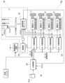
(制御信号40の具体例について)
図1Bは、制御信号40の具体例を示す図である。図1Bにおいて、図1Aに示した制御信号40は、減速(警報)信号41と、動作モード信号42と、異常時停止信号43とを含む。減速信号41は、セーフティーレーザスキャナ31によって警告領域内の物体が検出されると、セーフティーレーザスキャナ31から主制御器22へ出力される信号(図1Cの「WNG」)である。主制御器22は、減速信号41が入力されると、モータ制御回路23を制御して、全方向移動体1の速度を減速させる。(Specific examples of the control signal 40)
Fig. 1B is a diagram showing a specific example of the
動作モード信号42は、ドッキングモードに移行する場合などに、主制御器22から、を速度監視モジュール32へ出力される信号(図1Cの動作信号Sg)である。速度監視モジュール32は、動作モード信号42が入力されると、セーフティーレーザスキャナ31に設定される防護領域の範囲を一時的に小さく、または、防護領域の範囲を無効(ミューティング)にするための信号を出力する。The
異常時停止信号43は、速度監視モジュール32によって、全方向移動体1の速度が設計上の速度閾値に達している等の速度値の異常が判定された場合に、速度監視モジュール32から遮断器33へ出力される信号(図1Cの「OSSD」)である。遮断器33は、異常時停止信号43が入力されると、モータ制御回路23へ供給される電力を遮断する。これにより、全方向移動体1の速度を減速(停止)させる。The
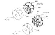
(メカナムホイール11a~11dの構成について)
図2は、メカナムホイール11a~11dの構成の一例を示す図である。図2において、メカナムホイール11a~11dは、それぞれ、複数の樽型ころ201を備える。複数の樽型ころ201は、車輪の外周上に車輪軸に対して傾いて取り付けてある。メカナムホイール11a~11dの車輪径は、いずれも同じ車輪径である。ただし、これらの車輪径は、異なる車輪径であってもよい。(Configuration of
Fig. 2 is a diagram showing an example of the configuration of the
図2において、中心線202は、樽型ころ201の傾きを示す。各メカナムホイール11a~11dにおいて、複数の樽型ころ201は、それぞれ、同方向に同じ回転速度で回転する。メカナムホイール11a~11dには、樽型ころ201が右上がりに傾いて取り付けられた右勝手と、樽型ころ201が左上がりに傾いて取り付けられた左勝手との2種類がある。メカナムホイール11a~11dは、それぞれ、4輪の自動車のように、全方向移動体1の筐体300(図3参照)の前後左右4か所に配置される。In Figure 2,
また、右側(または左側)に配置されメカナムホイール11a、11b(11c、11d)は、前後で異なる種類(右勝手と左勝手)が配置される。また、全方向移動体1の対角線上に配置されるメカナムホイール11a、11d(11b、11c)は、それぞれ同じ種類の右勝手(左勝手)が配置される。なお、メカナムホイール11a、11dと、メカナムホイール11b、11cとのうち、いずれを右勝手とするか左勝手とするかは、設計に応じて任意とすることができる。The
このようにメカナムホイール11a~11dを配置することにより、各車輪の発生する推進力のつり合いによって、移動体の進行方向および姿勢が安定する。例えば、各車輪を所定速度で回転させることにより、全方向移動体1を一方向に移動させることが可能である。例えば、前進、後進、真横に移動、旋回、斜め移動などが可能である。By arranging the
(全方向移動体1及びメカナムホイール11a~11dの座標系について)
図3は、全方向移動体1及びメカナムホイール11a~11dの座標系の一例を示す図である。図3に示すように、x軸と、y軸と、z軸とを右手座標系により定義する。x軸は、前後方向を示す。y軸は、横方向を示す。z軸は、高さ方向を示す。全方向移動体1の前進方向の速度を主移動速度Vxとする。全方向移動体1の横方向の速度をVyとする。全方向移動体1の旋回速度をωとする。(Coordinate system of omnidirectional
Fig. 3 is a diagram showing an example of a coordinate system for the omnidirectional
各メカナムホイール11の回転方向は、それぞれ、全方向移動体1への取り付け方向に向かって反時計方向を正(プラス)とする。また、メカナムホイール11aの車輪の回転速度をφ1とし、メカナムホイール11bの車輪の回転速度をφ2とし、メカナムホイール11cの車輪の回転速度をφ3とし、メカナムホイール11dの車輪の回転速度をφ4とする。The rotation direction of each Mecanum wheel 11 is positive (plus) in the counterclockwise direction toward the attachment direction to the
以下に、全方向移動体1が、前進する場合、真横に移動する場合、その場で旋回する場合のそれぞれについて、例示する。
(前進する場合)
φ1=-1rad/s、φ2=-1rad/s、φ3=1rad/s、φ4=1rad/sとすると、全方向移動体1は、x軸方向に1m/sの主移動速度Vxで前進移動する。
(真横に移動場合)
φ1=-1rad/s、φ2=1rad/s、φ3=-1rad/s、φ4=1rad/sとすると、全方向移動体1は、y軸方向に1m/sの速度Vyで横方向に移動する。
(その場で旋回する場合)
φ1=-0.5rad/s、φ2=-0.5rad/s、φ3=-0.5rad/s、φ4=-0.5rad/sとすると、全方向移動体1は、その場で、ω≒1rad/sの角速度で旋回する。 Below, examples will be given of the omnidirectional
(When moving forward)
If φ1=-1 rad/s, φ2=-1 rad/s, φ3=1 rad/s, and φ4=1 rad/s, the omnidirectional
(When moving directly to the side)
If φ1=-1 rad/s, φ2=1 rad/s, φ3=-1 rad/s, and φ4=1 rad/s, the omnidirectional
(When turning on the spot)
If φ1=-0.5 rad/s, φ2=-0.5 rad/s, φ3=-0.5 rad/s, and φ4=-0.5 rad/s, the omnidirectional
なお、回転、および並進方向の符号は、定義した座標系や向きと、メカナムホイール11の左右の種類の配置とによって決まる。例えば、定義した座標系や向きと、メカナムホイール11の左右の種類とが、図示とは異なる場合、移動方向の符号が、上記の例示と異なることになる。The signs of the rotational and translational directions are determined by the defined coordinate system and orientation, and the arrangement of the left and right types of Mecanum wheels 11. For example, if the defined coordinate system and orientation, and the left and right types of Mecanum wheels 11 are different from those shown in the figure, the signs of the movement directions will be different from those shown in the example above.
ここで、4個のメカナムホイール11を備える全方向移動体1について、各メカナムホイール11の回転速度と全方向移動体1の移動速度との関係について説明する。各メカナムホイール11の回転速度と全方向移動体1の移動速度とは、数式(1)で表すことができる。すなわち、全方向移動体1の移動速度は、各メカナムホイール11の回転速度から算出することが可能である。Here, for an omnidirectional

Aは3×4行列である。Rwは、車輪半径を示す。行列成分には、メカナムホイール11の車輪配置に関係する係数が入る。数式(1)は、順運動学と呼ばれる数式である。A is a 3x4 matrix. Rw indicates the wheel radius. The matrix elements contain coefficients related to the wheel arrangement of the Mecanum wheel 11. Equation (1) is called forward kinematics.
一方、数式(2)は、逆運動学と呼ばれる数式である。数式(2)は、全方向移動体1の目標速度から、必要な車輪回転速度を算出する計算式である。On the other hand, formula (2) is a formula called inverse kinematics. Formula (2) is a formula for calculating the required wheel rotation speed from the target speed of the omnidirectional

Bは4×3行列である。Rwは、車輪半径を示す。行列成分には、メカナムホイール11の車輪配置に関係する係数が入る。主制御器22は、数式(1)および数式(2)の関係を用いることにより、全方向移動体1の目標速度から、4つのメカナムホイール11の目標回転速度を算出する。主制御器22は、算出した目標回転速度をモータ制御回路23に出力することにより、全方向移動体1を所望の方向へ所望の速度で移動させることができる。B is a 4x3 matrix. Rw indicates the wheel radius. The matrix elements contain coefficients related to the wheel arrangement of the Mecanum wheels 11. The
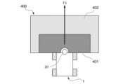
(監視領域400の一例について)
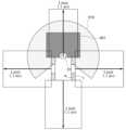
図4は、監視領域400の一例を示す図である。図4において、全方向移動体1の前方には、セーフティーレーザスキャナ31によって物体が検出される監視領域400が設定されている。監視領域400は、全方向移動体1に近い防護領域401と、防護領域401よりも遠方の警告領域402とを含む。(An example of the monitoring area 400)
Fig. 4 is a diagram showing an example of a
防護領域401は、全方向移動体1が停止するまでの距離を勘案して設定され、例えば、全方向移動体1の前方方向の50cm以内の領域である。防護領域401に障害物が存在することがセーフティーレーザスキャナ31によって検出されると、遮断器33(図1A参照)がモータ制御回路23に供給する電力を遮断することにより、全方向移動体1は停止する。The
警告領域402は、例えば、全方向移動体1の前方方向の50cm~数m以内の領域である。警告領域402に障害物が存在することがセーフティーレーザスキャナ31によって検出されると、主制御器22がモータ制御回路23を制御して、全方向移動体1を減速させる。監視領域400(防護領域401および警告領域402)は、それぞれ状況に応じて範囲が変更可能な領域である。The
(監視領域400の範囲の変更について)
図5Aは、変更された監視領域400の一例を示す図である。図5Aに示すように、全方向移動体1の前方には、搬送対象物500(かご台車)が存在する。すなわち、全方向移動体1が移動計画に基づいて、搬送対象物500を搬送するために、搬送対象物500に近付いた状況を示している。ここで、セーフティーレーザスキャナ31が搬送対象物500を障害物として検出してしまうと、全方向移動体1が停止し、搬送対象物500を搬送することができない。(Regarding change of range of monitoring area 400)
Fig. 5A is a diagram showing an example of the changed
そのため、搬送対象物500の近くに移動すると、一時的に防護領域401の範囲を小さくし(または無効にし)、搬送対象物500を障害物として検出しないようにする。また、警告領域402は、例えば、一時的に無効とされる。これにより、全方向移動体1は、搬送対象物500をピックアップすること(搬送対象物500の下に潜り込むこと)ができる。Therefore, when the omnidirectional
(非常停止用速度閾値の一例)
図5Bは、非常停止用速度閾値の一例を示す図である。図5Bに示すように、全方向移動体1の前方には、セーフティーレーザスキャナ31が検出可能な検出領域510がある。検出領域510は、全方向移動体1を中心に半径10m程度あり、また、全方向移動体1の前方270°に形成される。防護領域401は、検出領域510に含まれる。通常の走行において、非常停止用速度閾値は、例えば、全方向に1.1m/sに設定されている。すなわち、通常の走行において、全方向移動体1の移動速度が1.1m/sに達すると非常停止することを示している。なお、図5Bでは、前後方向(Vx方向)、左右方向(Vy方向)の速度閾値を図示しているが、斜め方向の速度や旋回速度(Vx、Vy、ω成分を含む速度)についても同様に設定できる。(An example of an emergency stop speed threshold)
FIG. 5B is a diagram showing an example of the speed threshold for emergency stop. As shown in FIG. 5B, there is a
図5Cは、ミューティング時の非常停止用速度閾値の一例を示す図である。図5Cに示すように、全方向移動体1の前方には防護領域401がなくなっており、すなわち、防護領域401が無効となっていることを示している。ミューティング時において、非常停止用速度閾値は、例えば、全方向に0.3m/sに設定されている。すなわち、ミューティング時の走行において、全方向移動体1の移動速度が0.3m/sに達すると非常停止することを示している。なお、図5Cでは、前後方向(Vx方向)、左右方向(Vy方向)の速度閾値を図示しているが、斜め方向の速度や旋回速度(Vx、Vy、ω成分を含む速度)についても同様に設定できる。Figure 5C is a diagram showing an example of an emergency stop speed threshold during muting. As shown in Figure 5C, there is no
(全方向移動体1の速度と、メカナムホイール11の回転速度との関係について)
メカナムホイール11の回転速度と全方向移動体1の速度は、数式(1)、数式(2)、数式(3)によって関係づけられ、計算できる。速度判定に用いる速度について、計算処理の簡略化のため、車輪毎の回転数を用いた条件判定および論理演算結果により速度を判定することも可能である。次にこの考え方を説明する。
図6は、全方向移動体1の速度と、メカナムホイール11の回転速度(角速度)との関係の一例を示す図である。図6において、横軸は、全方向移動体1の速度の絶対値|V|を示す。すなわち、|V|は数式(3)で表すことができる。(Relationship between the speed of the omnidirectional moving
The rotational speed of the Mecanum wheel 11 and the speed of the
Fig. 6 is a diagram showing an example of the relationship between the speed of the omnidirectional

縦軸は、4個のメカナムホイール11の回転速度のうち最大値の絶対値|φ|を示す。また、図6に示す|ω|は、全方向移動体1の旋回の回転速度(角速度)の絶対値を示す。|ω|は、0rad/s、0.25rad/s、0.5rad/sのうちのいずれかを示す。The vertical axis indicates the absolute value |φ| of the maximum rotational speed of the four Mecanum wheels 11. Also, |ω| shown in FIG. 6 indicates the absolute value of the rotational speed (angular velocity) of the omnidirectional
図6に示すように、例えば、回転速度|φ|(縦軸)が0.3rad/s以下(図中A)ならば、速度|V|(横軸)は、0.3m/s以下(図中B)となる、という関係が成り立つ。また、|ω|が大きくなったとしても、この関係は成り立つ。As shown in Figure 6, for example, if the rotation speed |φ| (vertical axis) is 0.3 rad/s or less (A in the figure), the speed |V| (horizontal axis) is 0.3 m/s or less (B in the figure). This relationship also holds true even if |ω| becomes large.
このため、4個のメカナムホイール11の回転速度のうち最大値の絶対値|φ|が0.3rad/s以下であることを判定することにより、全方向移動体1の速度|V|が0.3m/s以下であると(低速走行していると)見なすことができる。第1の実施形態では、4個のメカナムホイール11の回転速度をそれぞれ検出し、いずれもが、閾値(例えば、0.3rad/s)以下である場合に、低速走行しているものと見なして、防護領域401の範囲を縮小させる場合について説明する。Therefore, by determining that the absolute value |φ| of the maximum value among the rotational speeds of the four Mecanum wheels 11 is 0.3 rad/s or less, it is possible to consider the speed |V| of the omnidirectional
(速度判定のロジックについて)
図7は、第1の実施形態に係る速度判定のロジックを示す図である。図7に示すロジック700は、メカナムホイール11の各車輪の回転速度が閾値以下であるか否かを判定し、その判定結果の論理積を出力するロジックがある。具体的には、ロジック700は、回転速度φ1~φ4のいずれもが閾値N未満になると、すなわち、AND条件が成立すると、速度監視モジュール32が防護領域401の切り替え信号を出力するロジックを示す。また、当該AND条件が成立すると、速度監視モジュール32は、非常停止用速度閾値を変更する。(Regarding speed judgment logic)
7 is a diagram showing the logic of speed determination according to the first embodiment. The
一方で、回転速度検出器13a~13dによって検出されるメカナムホイール11a~11dの回転速度φ1~φ4のうち、いずれか1つでも閾値N以上であると、防護領域401の切り替え信号は出力されない。これにより、回転速度φ1~φ4のいずれもが閾値N未満になった場合に、すなわち、全方向移動体1が低速(低速値Vs以下)で走行した場合に、セーフティーレーザスキャナ31は、防護領域401の範囲を縮小することができる。また、回転速度φ1~φ4のいずれもが閾値N未満になった場合、速度監視モジュール32は、非常停止用速度閾値を第1非常停止用速度閾値(1.1m/s)から第2非常停止用速度閾値(0.3m/s)に変更することができる。On the other hand, if any one of the rotational speeds φ1 to φ4 of the
なお、本実施形態では、各メカナムホイール11a~11dの車輪径は、同一としたが、これに限らず、異なっていてもよい。各メカナムホイール11a~11dの車輪径が異なる場合には、ロジック700の回転速度の判定において、各車輪の回転速度に、換算係数を乗じて判定すればよい。また、ロジック700の回転速度の判定において、異なる閾値が設定されてもよい。In this embodiment, the wheel diameters of the
また、閾値Nは、1段階としたが、これに限らず、複数段階とすることも可能である。例えば、警告領域402の範囲を縮小させる場合には、閾値Nよりも大きい値の閾値を設定し、当該閾値を用いた論理積を出力することにより、警告領域402の範囲を縮小させることが可能である。なお、この場合、論理積の演算ロジックについては、多段階のロジックになり、また、信号の出力についても多段階の出力になる。Although the threshold value N has been set to one stage, it is not limited to this and can be set to multiple stages. For example, when reducing the range of the
また、図7および図9では、4個のメカナムホイール11の回転速度をそれぞれ検出し、いずれもが、閾値(例えば、0.3rad/s)以下である場合に、低速走行しているものと判別するようにしたが、これに限らない。例えば、各メカナムホイール11の回転速度の検出結果と数式(1)とを用いて移動速度を算出し、算出結果から低速走行していることを判別するようにしてもよい。In addition, in Figs. 7 and 9, the rotation speed of each of the four Mecanum wheels 11 is detected, and if all of them are below a threshold value (e.g., 0.3 rad/s), it is determined that the vehicle is traveling at a low speed, but this is not limited to the above. For example, the movement speed may be calculated using the detection results of the rotation speed of each Mecanum wheel 11 and formula (1), and it may be determined that the vehicle is traveling at a low speed from the calculation results.
(防護領域401および非常停止用速度閾値の切り替えを行う工程について)
図8は、第1の実施形態に係る全方向移動体1が行う、防護領域401および非常停止用速度閾値の切り替えを行う工程を示すフローチャートである。図8のステップS801において、速度監視モジュール32は、全方向移動体1の速度が低速値Vs(例えば0.3m/s)以下となるまで待機する。具体的には、速度監視モジュール32は、数式(1)を用いて計算した速度が速度閾値以下となるまで待機するか、もしくは回転速度検出器13a~13dによって検出されるメカナムホイール11a~11dの回転速度φ1~φ4のいずれもが閾値N(例えば0.3rad/s)未満となるまで待機する。(Regarding the process of switching the
8 is a flowchart showing a process of switching the
全方向移動体1の速度が低速値Vs以下になると、速度監視モジュール32が、セーフティーレーザスキャナ31へ、防護領域401の範囲を切り替えるための切り替え信号を出力する。これにより、セーフティーレーザスキャナ31は、防護領域401を縮小する(または無効にする)(ステップS802)。When the speed of the omnidirectional
そして、速度監視モジュール32は、非常停止用速度閾値Vtを第1非常停止用速度閾値(1.1m/s)から、第2非常停止用速度閾値(0.3m/s)に変更する(ステップS803)。ただし、非常停止用速度閾値Vtの第2非常停止用速度への変更は、全方向移動体1の速度が低速値Vs以下になることに限らず、主制御器22からミューティング信号が出力されたときとしてもよい。さらに、速度監視モジュール32は、現在の全方向移動体1の移動速度Vが第2非常停止用速度閾値(0.3m/s)以上であるか否かを判断する(ステップS804)。全方向移動体1の移動速度Vは、例えば、各メカナムホイール11の回転速度の検出結果と、数式(1)とを用いて算出することが可能である。Then, the
現在の全方向移動体1の移動速度Vが第2非常停止用速度閾値(0.3m/s)未満である場合(ステップS804:NO)、速度監視モジュール32は、ステップS806に進む。現在の全方向移動体1の移動速度Vが第2非常停止用速度閾値(0.3m/s)以上である場合(ステップS804:YES)、速度監視モジュール32は、異常時停止信号43を遮断器33へ出力する(ステップS805)。これにより、全方向移動体1は、非常停止する。If the current moving speed V of the omnidirectional moving
そして、速度監視モジュール32は、防護領域401の縮小が解除されたか否かを判断する(ステップS806)。防護領域401の縮小の解除は、移動計画に応じて行われる。防護領域401の縮小が解除されない場合(ステップS806:NO)、速度監視モジュール32は、ステップS804に戻る。防護領域401の縮小が解除された場合(ステップS806:YES)、非常停止用速度閾値Vtを第1非常停止用速度閾値(1.1m/s)に戻し(ステップS807)、一連の工程を終了する。なお、非常停止用速度閾値Vtの第2非常停止用速度への変更条件をミューティング信号の出力としたとすると、ステップS806では、主制御器22からのミューティング信号の出力が停止したか否かを判断するようにしてもよい。そして、当該信号の出力が停止した場合に、速度監視モジュール32は、非常停止用速度閾値Vtを第1非常停止用速度閾値(1.1m/s)に戻すようにしてもよい。Then, the
以上説明した、第1の実施形態の全方向移動体1によれば、全方向移動体1が低速で走行(低速値Vs以下)した場合に、セーフティーレーザスキャナ31の防護領域401の範囲を縮小することができる。これにより、搬送対象物500に近付いて低速走行した際に、セーフティーレーザスキャナ31が搬送対象物500を障害物として検出してしまうことを抑えることができる。したがって、全方向移動体1は、搬送対象物500をピックアップすること(搬送対象物500の下に潜り込むこと)ができ、搬送対象物500を搬送することができる。According to the omnidirectional
特に、第1の実施形態に係る全方向移動体1では、障害物を検出する複数のセンサなどを設けずに、メカナムホイール11の回転速度を用いて、防護領域401の範囲を縮小することができるため、簡単な構成で安全制御系Sfの制御を行うことができる。したがって、全方向移動体1を、簡単な構成で安全に動作させることができる。In particular, in the omnidirectional
また、第1の実施形態の全方向移動体1によれば、防護領域401を縮小した際に、全方向移動体1が第2非常停止用速度閾値以上の移動速度で動作することを抑えることができる。すなわち、搬送対象物500に近付いて低速走行した際に、全方向移動体1が第2非常停止用速度閾値以上の移動速度で動作することを抑えることができる。このため、全方向移動体1が搬送対象物500等に接触することを抑えることができ、全方向移動体1を安全に動作させることができる。Furthermore, according to the omnidirectional
また、防護領域401を縮小しないとき(全方向移動体1が低速走行しないとき)には、非常停止用速度閾値を下げないため、全方向移動体1を非常停止させにくくすることができる。したがって、全方向移動体1の移動効率が低下することを抑えることができる。In addition, when the
(第1の実施形態の変形例1)
上述した第1の実施形態では、図7に示したように、各車輪の回転速度が閾値以下であることの論理積の出力結果に応じて、防護領域401の範囲および非常停止用速度閾値を変更させる場合について説明した。第1の実施形態の変形例1では、「各車輪の回転速度が閾値以下であることの論理積」と、「主制御器22から出力される動作信号」との論理積に応じて、防護領域401の範囲および非常停止用速度閾値を変更させる場合について説明する。なお、以下の各変形例および他の実施形態において、第1の実施形態で説明した内容と同様の内容については、同様の符号を付すとともに、適宜説明を省略する。(
In the above-described first embodiment, as shown in Fig. 7, a case has been described in which the range of the
(防護領域401および非常停止用速度閾値の切り替えのロジックについて)
図9は、第1の実施形態の変形例1に係る防護領域401および非常停止用速度閾値の切り替えのロジックを示す図である。図9に示すロジック900は、ロジック700の出力結果と、主制御器22からの動作信号との論理積を出力するロジックである。主制御器22からの動作信号は、搬送対象物500(かご台車)とドッキング(ピックアップする際の動作)する場合など、目標とする移動計画に応じて、主制御器22から出力される信号である。この動作信号の入力と、ロジック700に示す速度の判定結果との、AND条件の成立により、速度監視モジュール32は、防護領域401を縮小させるための信号を出力する。また、当該AND条件が成立すると、速度監視モジュール32は、非常停止用速度閾値を第1非常停止用速度閾値(1.1m/s)から第2非常停止用速度閾値(0.3m/s)に変更する。(Regarding
FIG. 9 is a diagram showing the logic of switching the
(防護領域401および非常停止用速度閾値の切り替えを行う工程について)
図10は、第1の実施形態の変形例1に係る全方向移動体1が行う、防護領域401および非常停止用速度閾値の切り替えを行う工程を示すシーケンス図である。図10のステップS1001において、主制御器22は、移動計画を参照し、全方向移動体1の搬送対象物500の搬送開始を示すドッキングモードの開始となるまで待機する。ドッキングモードの開始となると、主制御器22は、速度監視モジュール32へ動作信号(例えば、ミューティング信号)を出力する(ステップS1002)。(Regarding the process of switching the
Fig. 10 is a sequence diagram showing a process of switching the
一方、速度監視モジュール32は、ステップS1003において、全方向移動体1の速度が低速値Vs以下となるまで待機する。具体的には、速度監視モジュール32は、回転速度検出器13a~13dによって検出されるメカナムホイール11a~11dの回転速度φ1~φ4のいずれもが閾値N未満となるまで待機する。なお、全方向移動体1の速度は、各メカナムホイール11の回転速度の検出結果と数式(1)とを用いて算出するようにしてもよい。Meanwhile, in step S1003, the
全方向移動体1の速度が低速値Vs以下になり、且つ、主制御器22から動作信号を入力すると、すなわち、AND条件が成立すると、速度監視モジュール32は、セーフティーレーザスキャナ31に対して、防護領域401の範囲を切り替えるための切り替え信号を出力する。これにより、セーフティーレーザスキャナ31は、防護領域401を縮小する(または無効にする)(ステップS1004)。When the speed of the omnidirectional
そして、速度監視モジュール32は、非常停止用速度閾値Vtを第1非常停止用速度閾値(1.1m/s)から、第2非常停止用速度閾値(0.3m/s)に変更する(ステップS1005)。ただし、非常停止用速度閾値Vtを第2非常停止用速度へ変更する条件は、上記AND条件の成立に限らず、主制御器22からミューティング信号が出力されることとしてもよい。さらに、速度監視モジュール32は、現在の全方向移動体1の移動速度Vが第2非常停止用速度閾値(0.3m/s)以上であるか否かを判断する(ステップS1006)。全方向移動体1の移動速度Vは、例えば、各メカナムホイール11の回転速度の検出結果と、数式(1)とを用いて算出することが可能である。Then, the
現在の全方向移動体1の移動速度Vが第2非常停止用速度閾値(0.3m/s)未満である場合(ステップS1006:NO)、速度監視モジュール32は、ステップS1008に進む。現在の全方向移動体1の移動速度Vが第2非常停止用速度閾値(0.3m/s)以上である場合(ステップS1006:YES)、速度監視モジュール32は、異常時停止信号43を遮断器33へ出力する(ステップS1007)。これにより、全方向移動体1は、非常停止する。If the current moving speed V of the omnidirectional moving
そして、速度監視モジュール32は、上記AND条件の成立が終了したか否かを判断する(ステップS1008)。上記AND条件の成立が終了しない場合(ステップS1008:NO)、速度監視モジュール32は、ステップS1006に戻る。上記AND条件の成立が終了した場合(ステップS1008:YES)、防護領域401の縮小を解除するとともに、非常停止用速度閾値Vtを第1非常停止用速度閾値(1.1m/s)に戻し(ステップS1009)、一連の工程を終了する。なお、非常停止用速度閾値Vtの第2非常停止用速度への変更条件をミューティング信号の出力としたとすると、ステップS1008では、主制御器22からのミューティング信号の出力が停止したか否かを判断するようにしてもよい。そして、当該信号の出力が停止した場合に、速度監視モジュール32は、非常停止用速度閾値Vtを第1非常停止用速度閾値(1.1m/s)に戻すようにしてもよい。Then, the
第1の実施形態に係る変形例1によれば、ドッキングモードが開始されて、搬送対象物500が配置される位置の近くで全方向移動体1が低速走行(低速値Vs以下)した際に、セーフティーレーザスキャナ31によって搬送対象物500が障害物として検出されないようにすることができる。すなわち、全方向移動体1が低速走行したとしても、搬送対象物500の近く以外では、防護領域401を縮小しないようにすることができる。したがって、搬送対象物500の近く以外などの不適切な位置で防護領域401の範囲を縮小させることによって、安全性が低下してしまうことを抑えることができる。また、より適切なタイミングで防護領域401の範囲を縮小できるため、全方向移動体1が行う搬送の効率化を図ることができる。According to the first modification of the first embodiment, when the docking mode is started and the omnidirectional
また、第1の実施形態に係る変形例1によれば、ドッキングモードが開始されて、搬送対象物500の近くで全方向移動体1が低速走行(低速値Vs以下)した際に、非常停止用速度閾値Vtを下げることができる。すなわち、全方向移動体1が低速走行したとしても、搬送対象物500の近く以外では、非常停止用速度閾値Vtを下げないようにすることができる。したがって、搬送対象物500の近く以外で、全方向移動体1を非常停止させにくくすることができる。したがって、全方向移動体1の移動効率が低下することを抑えることができる。In addition, according to the first modification of the first embodiment, when the docking mode is started and the omnidirectional moving
(第1の実施形態の変形例2)
上述した第1の実施形態では、図7に示したように、各車輪の回転速度の判定結果を用いた論理積の出力結果に応じて、防護領域401の範囲および非常停止用速度閾値を変更させる場合について説明した。第1の実施形態の変形例2では、「各車輪の回転速度が閾値以下であることの論理積」と、「メカナムホイール11のそれぞれの回転速度を用いて算出した算出値」との論理和に応じて、防護領域401の範囲および非常停止用速度閾値を変更させる場合について説明する。(
In the above-described first embodiment, a case has been described in which the range of the
ここで言う算出値とは、全方向移動体1のx方向(「主進行方向」ともいう)の主移動速度Vxである。変形例2では、主移動速度Vxが負となる場合、すなわち、主進行方向に対して、全方向移動体1が後退する場合に、防護領域401の範囲を縮小させることについて説明する。主進行方向に対して、全方向移動体1が後退しているか否かは、数式(4)によって判定することができる。The calculated value referred to here is the main movement speed Vx of the omnidirectional moving

数式(4)の左辺は、主移動速度Vxを示す。数式(4)を満たす場合、全方向移動体1が後退していると判定できる。The left side of formula (4) indicates the main moving speed Vx. When formula (4) is satisfied, it can be determined that the omnidirectional moving
(防護領域401および非常停止用速度閾値の切り替えのロジックについて)
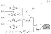
図11は、第1の実施形態の変形例2に係る防護領域401および非常停止用速度閾値の切り替えのロジックを示す図である。図11に示すロジック1100は、ロジック700の出力結果と、全方向移動体1が後退していることの判定結果との、論理和(OR条件の結果)を出力するロジックである。このロジック1100を用いて、これらのOR条件が成立することにより、速度監視モジュール32は、防護領域401を縮小させるための信号を出力する。また、OR条件が成立すると、速度監視モジュール32は、非常停止用速度閾値を第1非常停止用速度閾値(1.1m/s)から第2非常停止用速度閾値(0.3m/s)に変更する。(Regarding
11 is a diagram showing a logic for switching the
(防護領域401および非常停止用速度閾値の切り替えを行う工程について)
図12は、第1の実施形態の変形例2に係る全方向移動体1が行う、防護領域401および非常停止用速度閾値の切り替えを行う工程を示すシーケンス図である。図12のステップS1201において、速度監視モジュール32は、全方向移動体1の速度が低速値Vs以下となるまで待機する。具体的には、速度監視モジュール32は、回転速度検出器13a~13dによって検出されるメカナムホイール11a~11dの回転速度φ1~φ4のいずれもが閾値N未満となるまで待機する。なお、全方向移動体1の速度は、各メカナムホイール11の回転速度の検出結果と数式(1)とを用いて算出するようにしてもよい。(Regarding the process of switching the
12 is a sequence diagram showing a process of switching the
また、速度監視モジュール32は、ステップS1202において、全方向移動体1が後退することを示す、主移動速度Vxが0未満になるまで(-(φ1+φ2)+(φ3+φ4)<0を満たすまで)待機する。全方向移動体1の速度が低速値Vs以下になるか、もしくは、主移動速度Vxが0未満になると、すなわち、OR条件を満たすと、速度監視モジュール32は、セーフティーレーザスキャナ31に対して、防護領域401の範囲を切り替えるための切り替え信号を出力する。これにより、セーフティーレーザスキャナ31は、防護領域401を縮小する(または無効にする)(ステップS1203)。In addition, in step S1202, the
そして、速度監視モジュール32は、非常停止用速度閾値Vtを第1非常停止用速度閾値(1.1m/s)から、第2非常停止用速度閾値(0.3m/s)に変更する(ステップS1204)。ただし、非常停止用速度閾値Vtを第2非常停止用速度へ変更する条件は、上記OR条件の成立に限らず、主制御器22からミューティング信号が出力されることとしてもよい。さらに、速度監視モジュール32は、現在の全方向移動体1の移動速度Vが第2非常停止用速度閾値(0.3m/s)以上であるか否かを判断する(ステップS1205)。全方向移動体1の移動速度Vは、例えば、各メカナムホイール11の回転速度の検出結果と、数式(1)とを用いて算出することが可能である。Then, the
現在の全方向移動体1の移動速度Vが第2非常停止用速度閾値(0.3m/s)未満である場合(ステップS1205:NO)、速度監視モジュール32は、ステップS1207に進む。現在の全方向移動体1の移動速度Vが第2非常停止用速度閾値(0.3m/s)以上である場合(ステップS1205:YES)、速度監視モジュール32は、異常時停止信号43を遮断器33へ出力する(ステップS1206)。これにより、全方向移動体1は、非常停止する。If the current moving speed V of the omnidirectional moving
そして、速度監視モジュール32は、上記OR条件の成立が終了したか否かを判断する(ステップS1207)。上記OR条件の成立が終了しない場合(ステップS1207:NO)、速度監視モジュール32は、ステップS1205に戻る。上記OR条件の成立が終了した場合(ステップS1207:YES)、防護領域401の縮小を解除するとともに、非常停止用速度閾値Vtを第1非常停止用速度閾値(1.1m/s)に戻し(ステップS1208)、一連の工程を終了する。なお、非常停止用速度閾値Vtの第2非常停止用速度への変更条件をミューティング信号の出力としたとすると、ステップS1207では、主制御器22からのミューティング信号の出力が停止したか否かを判断するようにしてもよい。そして、当該信号の出力が停止した場合に、速度監視モジュール32は、非常停止用速度閾値Vtを第1非常停止用速度閾値(1.1m/s)に戻すようにしてもよい。Then, the
第1の実施形態に係る変形例2によれば、全方向移動体1の移動速度が低下したとき(低速値Vs以下)のみならず、全方向移動体1が後退するときにも、防護領域401の範囲を縮小させることができる。例えば、全方向移動体1が搬送対象物500の近くで、搬送対象物500に対する向き(正対する向き)を整える場合など後退するような場合でも、防護領域401の範囲を適切に縮小させ、搬送対象物500を障害物として検出しないようにすることができる。したがって、全方向移動体1が行う搬送の効率化を図ることができる。According to the second modification of the first embodiment, the range of the
また、第1の実施形態に係る変形例2によれば、全方向移動体1の移動速度が低下したとき(低速値Vs以下)のみならず、全方向移動体1が後退するときにも、非常停止用速度閾値Vtを下げることができる。例えば、全方向移動体1が搬送対象物500の近くで、搬送対象物500に対する向き(正対する向き)を整える場合など後退するような場合に、全方向移動体1の後方の移動速度が第2非常停止用速度閾値以上の移動速度となることを抑えることができるため、全方向移動体1を安全に動作させることができる。Furthermore, according to the second modification of the first embodiment, the emergency stop speed threshold Vt can be lowered not only when the moving speed of the omnidirectional moving
本変形例2において、速度監視モジュール32は、全方向移動体1が後退する場合には、後方のみ、第2非常停止用速度閾値(0.3m/s)に変更してもよい。具体的には、速度監視モジュール32は、全方向移動体1が後退するのか否かを判別するようにし、全方向移動体1が後退すると判別した場合に、後方のみ、非常停止用速度閾値を変更すればよい。これにより、後方についてのみ、全方向移動体1の移動速度が第2非常停止用速度閾値以上の移動速度で動作することを抑えることができる。また、後方以外については、非常停止用速度閾値を下げないため、後方以外については全方向移動体1を非常停止させにくくすることができる。したがって、全方向移動体1の移動効率が低下することをより抑えることができる。In this second modification, the
(第1の実施形態の変形例3)
上述した第1の実施形態の変形例1では、「各車輪の回転速度が閾値以下であることの論理積」と、「主制御器22から出力される動作信号」との論理積に応じて、防護領域401の範囲および非常停止用速度閾値を変更させる場合について説明した。第1の実施形態の変形例3では、変形例1で説明した「各車輪の回転速度が閾値以下であることの論理積と、主制御器22からの動作信号との論理積」と、変形例2で説明した「メカナムホイール11のそれぞれの回転速度を用いて算出した算出値」との、論理和に応じて、防護領域401の範囲および非常停止用速度閾値を変更させる場合について説明する。(
In the above-described first modification of the first embodiment, a case has been described in which the range of the
(防護領域401および非常停止用速度閾値の切り替えを行う工程について)
図13は、第1の実施形態の変形例3に係る全方向移動体1が行う、防護領域401および非常停止用速度閾値の切り替えを行う工程を示すシーケンス図である。図13のステップS1301において、主制御器22は、移動計画を参照し、全方向移動体1の搬送対象物500の搬送開始を示すドッキングモードの開始となるまで待機する。ドッキングモードの開始となると、主制御器22は、速度監視モジュール32へ動作信号(例えば、ミューティング信号)を出力する(ステップS1302)。(Regarding the process of switching the
Fig. 13 is a sequence diagram showing a process of switching the
一方、速度監視モジュール32は、ステップS1303において、全方向移動体1の速度が低速値Vs以下となるまで待機する。具体的には、速度監視モジュール32は、回転速度検出器13a~13dによって検出されるメカナムホイール11a~11dの回転速度φ1~φ4のいずれもが閾値N未満となるまで待機する。なお、全方向移動体1の速度は、各メカナムホイール11の回転速度の検出結果と数式(1)とを用いて算出するようにしてもよい。On the other hand, in step S1303, the
また、速度監視モジュール32は、ステップS1304において、全方向移動体1が後退することを示す、主移動速度Vxが0未満になるまで(-(φ1+φ2)+(φ3+φ4)<0を満たすまで)待機する。In addition, in step S1304, the
(1)「全方向移動体1の速度が低速値Vs以下になり、且つ、主制御器22からの動作信号の入力がある」というAND条件が成立するか、もしくは、(2)主移動速度Vxが0未満になると、すなわち、(1)と(2)のOR条件が成立したとする。この場合、速度監視モジュール32は、セーフティーレーザスキャナ31に対して、防護領域401の範囲を切り替えるための切り替え信号を出力する。これにより、セーフティーレーザスキャナ31は、防護領域401を縮小する(または無効にする)(ステップS1305)。(1) The AND condition that "the speed of the omnidirectional
そして、速度監視モジュール32は、非常停止用速度閾値Vtを第1非常停止用速度閾値(1.1m/s)から、第2非常停止用速度閾値(0.3m/s)に変更する(ステップS1306)。ただし、非常停止用速度閾値Vtを第2非常停止用速度へ変更する条件は、上記OR条件の成立に限らず、主制御器22からミューティング信号が出力されることとしてもよい。さらに、速度監視モジュール32は、現在の全方向移動体1の移動速度Vが第2非常停止用速度閾値(0.3m/s)以上であるか否かを判断する(ステップS1307)。全方向移動体1の移動速度Vは、例えば、各メカナムホイール11の回転速度の検出結果と、数式(1)とを用いて算出することが可能である。Then, the
現在の全方向移動体1の移動速度Vが第2非常停止用速度閾値(0.3m/s)未満である場合(ステップS1307:NO)、速度監視モジュール32は、ステップS1309に進む。現在の全方向移動体1の移動速度Vが第2非常停止用速度閾値(0.3m/s)以上である場合(ステップS1307:YES)、速度監視モジュール32は、異常時停止信号43を遮断器33へ出力する(ステップS1308)。これにより、全方向移動体1は、非常停止する。If the current moving speed V of the omnidirectional moving
そして、速度監視モジュール32は、上記(1)、(2)のOR条件の成立が終了したか否かを判断する(ステップS1309)。上記(1)、(2)のOR条件の成立が終了しない場合(ステップS1309:NO)、速度監視モジュール32は、ステップS1307に戻る。上記(1)、(2)のOR条件の成立が終了した場合(ステップS1309:YES)、防護領域401の縮小を解除するとともに、非常停止用速度閾値Vtを第1非常停止用速度閾値(1.1m/s)に戻し(ステップS1310)、一連の工程を終了する。なお、本変形例3において、速度監視モジュール32は、全方向移動体1が後退する場合には、後方のみ、第2非常停止用速度閾値(0.3m/s)に変更してもよい。また、非常停止用速度閾値Vtの第2非常停止用速度への変更条件をミューティング信号の出力としたとすると、ステップS1309では、主制御器22からのミューティング信号の出力が停止したか否かを判断するようにしてもよい。そして、当該信号の出力が停止した場合に、速度監視モジュール32は、非常停止用速度閾値Vtを第1非常停止用速度閾値(1.1m/s)に戻すようにしてもよい。Then, the
第1の実施形態に係る変形例3によれば、変形例1および変形例2の両方の効果を得ることができる。すなわち、全方向移動体1の安全性が低下してしまうことを抑えることができるとともに、全方向移動体1が行う搬送の効率化を図ることができる。According to the
(第1の実施形態の変形例4)
上述した第1の実施形態では、図7に示したように、各車輪の回転速度の判定に用いられる閾値を1種類(閾値Nのみ)とし、回転速度の判定を1段階とした場合について説明した。第1の実施形態の変形例4では、各車輪の回転速度の判定に用いられる閾値を車輪ごとに異なる閾値とし、また、回転速度の判定を複数段階(2段階)にして、防護領域401の範囲を縮小させる場合について説明する。変形例4では、ドッキングモードに入る前の特定の動作であることを判別することにより、防護領域401の範囲を縮小させるとともに、非常停止用速度閾値を変更する場合について説明する。(Fourth Modification of the First Embodiment)
In the above-described first embodiment, as shown in Fig. 7, a case has been described in which one type of threshold (only threshold N) is used to determine the rotation speed of each wheel, and the rotation speed is determined in one stage. In the fourth modification of the first embodiment, a case will be described in which a different threshold is used to determine the rotation speed of each wheel, and the rotation speed is determined in multiple stages (two stages), thereby reducing the range of the
(防護領域401の切り替えのロジックについて)
図14は、第1の実施形態の変形例4に係る防護領域401の切り替えのロジックを示す図である。図14に示すロジック1400は、メカナムホイール11の各車輪の回転速度が、それぞれ同一または異なる閾値以下であるか否かを判定し、その判定結果の論理積を出力するロジックがある。(Logic for switching the protection area 401)
Fig. 14 is a diagram showing the logic for switching the
図14に示す車輪ごとに設定される閾値A1~A4、B1~B4は、ドッキングモードに入る前の特定の動作を判別するための値である。速度監視モジュール32は、回転速度検出器13aによって検出されるメカナムホイール11aの回転速度φ1が閾値A1未満となると、さらに、その後に、回転速度φ1が閾値B1未満となるまで待機する。The thresholds A1 to A4 and B1 to B4 set for each wheel shown in FIG. 14 are values for determining specific operations before entering docking mode. When the rotational speed φ1 of the
同様に、速度監視モジュール32は、回転速度検出器13b~13dによって検出されるメカナムホイール11b~dの回転速度φ2~φ4がそれぞれ閾値A2~A4未満となると、さらに、その後に、回転速度φ2~φ4が閾値B2~B4未満となるまで待機する。Similarly, when the rotational speeds φ2 to φ4 of the
速度監視モジュール32は、回転速度φ1~φ4がいずれも、順次条件が成立していき、図14に示す2段階の条件を全て満たすと、すなわち、AND条件が成立すると、ドッキングモードに入る前の特定の動作が行われたものと見なさせる。このため、速度監視モジュール32から、セーフティーレーザスキャナ31に対して、防護領域401の範囲を切り替えるための切り替え信号が出力される。これにより、セーフティーレーザスキャナ31は、防護領域401を縮小(または無効にし)する。また、速度監視モジュール32は、非常停止用速度閾値を第1非常停止用速度閾値(1.1m/s)から第2非常停止用速度閾値(0.3m/s)に変更する。なお、特定の動作が行われたか否かは、上記ロジックから得ることに限らず、各メカナムホイール11の回転速度の検出結果と数式(1)とを用いた算出結果から得ることも可能である。The
また、主制御器22は、所定時間が経過すると動作信号を出力する。これにより、セーフティーレーザスキャナ31は、防護領域401の縮小または無効や、非常停止用速度閾値の変更をリセットする。なお、速度監視モジュール32が主制御器22から動作信号を入力することにより、セーフティーレーザスキャナ31にリセットの指示を行うようにしてもよい。すなわち、セーフティーレーザスキャナ31は、速度監視モジュール32からの指示に基づいて、防護領域401の縮小または無効や、非常停止用速度閾値の変更をリセットしてもよい。また、セーフティーレーザスキャナ31は、主制御器22から直接、リセットを示す動作信号を入力することにより、防護領域401の縮小または無効や、非常停止用速度閾値の変更をリセットしてもよい。Furthermore, the
また、セーフティーレーザスキャナ31は、タイマの計測結果に基づいて、防護領域401の縮小または無効や、非常停止用速度閾値の変更をリセットしてもよい。タイマは、速度監視モジュール32に設けられていてもよいし、セーフティーレーザスキャナ31に設けられていてもよい。また、タイマは、例えば、ドッキングモードにおける動作に要する時間を計測できればよい。速度監視モジュール32にタイマが設けられている場合、セーフティーレーザスキャナ31は、速度監視モジュール32からのタイマの計測結果に基づく指示に基づいて、防護領域401の縮小または無効や、非常停止用速度閾値の変更をリセットしてもよい。The
第1の実施形態に係る変形例4によれば、全方向移動体1がドッキングモードに入る前の特定の動作を行った際に、セーフティーレーザスキャナ31によって搬送対象物500が障害物として検出されないようにすることができる。したがって、防護領域401の範囲を縮小させることによって、安全性が低下してしまうことを抑えることができる。また、より適切なタイミングで防護領域401の範囲を縮小できるため、全方向移動体1が行う搬送の効率化を図ることができる。また、搬送対象物500の近くにおいて、全方向移動体1が第2非常停止用速度閾値以上の移動速度となることを抑えることができるため、全方向移動体1を安全に動作させることができる。According to the fourth modification of the first embodiment, when the omnidirectional
さらに、第1の実施形態に係る変形例4によれば、主制御器22からの動作信号を用いなくても、ドッキングモードに入る前の特定の動作であることを判別して、防護領域401の範囲および非常停止用速度閾値を変更させることができる。これにより、主制御器22が行う動作信号の出力に係る負荷を抑えることができる。Furthermore, according to the fourth modification of the first embodiment, it is possible to determine that a specific operation has occurred before entering the docking mode, and to change the range of the
なお、第1の実施形態に係る変形例4に、第1の実施形態に係る変形例1を適用してもよい。すなわち、主制御器22から出力される動作信号を用いて、防護領域401の範囲および非常停止用速度閾値を変更させるようにしてもよい。具体的には、「回転速度φ1~φ4が図14に示す2段階の条件を全て満たしたことの論理積」と、「主制御器22から出力される動作信号」との論理積に応じて、防護領域401の範囲および非常停止用速度閾値を変更してもよい。Note that modified example 1 according to the first embodiment may be applied to modified example 4 according to the first embodiment. That is, the range of the
これにより、搬送対象物500が配置される位置で、全方向移動体1が特定の動作を行った際(搬送対象物500とドッキングする際)に、セーフティーレーザスキャナ31によって搬送対象物500が障害物として検出されないようにすることができる。したがって、不適切な位置で、防護領域401の範囲を縮小させることによって、安全性が低下してしまうことを抑えることができる。また、より適切なタイミングで防護領域401の範囲を縮小できるため、全方向移動体1が行う搬送の効率化を図ることができる。また、監視領域を縮小させた際(搬送対象物500とドッキングする際)に、全方向移動体1が第2非常停止用速度閾値以上の移動速度となることを抑えることができるため、全方向移動体1を安全に動作させることができる。This prevents the
(第1の実施形態の変形例5)
上述した第1の実施形態では、各車輪の回転速度のみに応じて、防護領域401の範囲および非常停止用速度閾値を変更させる場合について説明した。第1の実施形態の変形例5では、「各車輪の回転速度が閾値以下であることの論理積」と、「回転異常の検出結果」との論理積に応じて、防護領域401の範囲および非常停止用速度閾値を変更させる場合について説明する。Fifth Modification of the First Embodiment
In the above-described first embodiment, a case has been described in which the range of the
メカナムホイール11の各車輪の回転速度について、異常を検出するには、数式(5)、数式(6)が用いられる。To detect abnormalities in the rotational speed of each wheel of the Mecanum wheel 11, formulas (5) and (6) are used.


回転速度検出器13に異常が無く、さらに、路面と車輪間との間に滑りがない理想的な状態では、数式(5)に示す「|h|」は、ゼロとなる。一方で、φ1~φ4の少なくともいずれかの値が異常値を示す場合には、「|h|」はゼロ以外の値を示す。そこで「ξ」を許容値として設定することにより、数式(6)によって異常値を判定できる。In an ideal state where there is no abnormality in the
ここで、上述した順運動学の数式(1)において、φ1、φ2、φ3、φ4と、Vx、Vy、ωとの関係を示した。数式(1)において、φ1、φ2、φ3、φ4は、理論上は任意の値がとることができるが、実際には路面と車輪との間の拘束条件により、任意の値をとることはできない。Here, the relationship between φ1, φ2, φ3, and φ4 and Vx, Vy, and ω is shown in the above-mentioned formula (1) of forward kinematics. In formula (1), φ1, φ2, φ3, and φ4 can theoretically take any value, but in reality they cannot take any value due to constraints between the road surface and the wheels.
一方で、上述した逆運動学の数式(2)では、Vx、Vy、ωは、任意の値をとることができる。数式(6)は、数式(1)で拘束条件から外れたφ1~φ4のいずれかの値が入力されたことを判定する式である。On the other hand, in the inverse kinematics equation (2) described above, Vx, Vy, and ω can take any value. Equation (6) is an equation that determines whether any of the values φ1 to φ4 that deviate from the constraint condition in equation (1) has been input.
順運動学の数式(1)を用いて、
φ1=-1、φ2=-1、φ3=1、φ4=1、とすると、
Vx=1、Vy=0、ω=0
である。
このとき、|h|=0である。 Using the equation (1) of forward kinematics,
If φ1 = -1, φ2 = -1, φ3 = 1, and φ4 = 1, then
Vx=1, Vy=0, ω=0
It is.
In this case, |h|=0.
次に、順運動学の数式(1)を用いて、
φ1=0、φ2=-1、φ3=1、φ4=1、とすると、
Vx=0.75、Vy=-0.25、ω=-0.4835
である。
このとき、|h|=1である。
h≠0であるため、一部の車輪の回転速度に異常があると判定できる。 Next, using the equation (1) of forward kinematics,
If φ1 = 0, φ2 = -1, φ3 = 1, and φ4 = 1, then
Vx=0.75, Vy=-0.25, ω=-0.4835
It is.
In this case, |h|=1.
Since h≠0, it can be determined that there is an abnormality in the rotation speed of some of the wheels.
得られたVx、Vy、ωを逆運動学の数式(2)に代入してみると、
φ1=-0.249、φ2=-0.749、φ3=1.250、φ4=0.75
となり、入力した値である、
φ1=0、φ2=-1、φ3=1、φ4=1
と矛盾することからも、一部の車輪の回転速度に異常があると判定できる。 Substituting the obtained Vx, Vy, and ω into the inverse kinematics equation (2), we get
φ1=-0.249, φ2=-0.749, φ3=1.250, φ4=0.75
This is the input value,
φ1=0, φ2=-1, φ3=1, φ4=1
This contradiction also indicates that there is something wrong with the rotation speed of some of the wheels.
(防護領域401の切り替えを行う工程について)
図15は、第1の実施形態の変形例5に係る全方向移動体1が行う、防護領域401および非常停止用速度閾値の切り替えを行う工程を示すシーケンス図である。図15のステップS1501において、速度監視モジュール32は、全方向移動体1の速度が低速値Vs以下となるまで待機する。具体的には、速度監視モジュール32は、回転速度検出器13a~13dによって検出されるメカナムホイール11a~11dの回転速度φ1~φ4のいずれもが閾値N未満となるまで待機する。(Regarding the process of switching the protection area 401)
15 is a sequence diagram showing a process of switching the
また、速度監視モジュール32は、ステップS1502において、異常を検出するまで、すなわち、「|h|<ξ」となるまで待機する。異常を検出すると、ステップS1503において、速度監視モジュール32は、一定時間持続したか否かを判定する。ここで、一定時間持続したか否かの判定を行うには、例えば、平均化フィルタが用いられる。これによって、ノイズや一時的な車輪の滑りによって、回転異常と判定してしまい、停止してしまうことを抑えることができる。In addition, in step S1502, the
異常が一定時間持続しない場合には、NOT条件が成立する。このNOT条件の成立と、ステップS1501において全方向移動体1の速度が低速値Vs以下になることとの、AND条件が成立したとする。この場合、速度監視モジュール32は、セーフティーレーザスキャナ31に対して、防護領域401の範囲を切り替えるための切り替え信号を出力する。これにより、セーフティーレーザスキャナ31は、防護領域401を縮小する(または無効にする)(ステップS1504)。If the abnormality does not persist for a certain period of time, the NOT condition is satisfied. Assume that the AND condition is satisfied when this NOT condition is satisfied and the speed of the omnidirectional
一方で、異常が一定時間持続した場合には、速度監視モジュール32は、全方向移動体1を停止させるための保護停止信号を出力する。保護停止信号は、速度監視モジュール32から遮断器33へ直接、または、他の機器(主制御器22、モータ制御回路23、セーフティーレーザスキャナ31など)を介して、遮断器33へ出力される。遮断器33は、停止信号を入力すると、駆動モータ12を停止させ(ステップS1505)、一連の工程を終了する。On the other hand, if the abnormality continues for a certain period of time, the
ステップS1504において防護領域401を縮小した後、速度監視モジュール32は、非常停止用速度閾値Vtを第1非常停止用速度閾値(1.1m/s)から、第2非常停止用速度閾値(0.3m/s)に変更する(ステップS1506)。ただし、非常停止用速度閾値Vtを第2非常停止用速度へ変更する条件は、上記AND条件の成立に限らず、主制御器22からミューティング信号が出力されることとしてもよい。さらに、速度監視モジュール32は、現在の全方向移動体1の移動速度Vが第2非常停止用速度閾値(0.3m/s)以上であるか否かを判断する(ステップS1507)。全方向移動体1の移動速度Vは、例えば、各メカナムホイール11の回転速度の検出結果と、数式(1)とを用いて算出することが可能である。After reducing the
現在の全方向移動体1の移動速度Vが第2非常停止用速度閾値(0.3m/s)未満である場合(ステップS1507:NO)、速度監視モジュール32は、ステップS1509に進む。現在の全方向移動体1の移動速度Vが第2非常停止用速度閾値(0.3m/s)以上である場合(ステップS1507:YES)、速度監視モジュール32は、異常時停止信号43を遮断器33へ出力する(ステップS1508)。これにより、全方向移動体1は、非常停止する。If the current moving speed V of the omnidirectional moving
そして、速度監視モジュール32は、上記AND条件が終了したか否かを判断する(ステップS1509)。上記AND条件が終了しない場合(ステップS1509:NO)、速度監視モジュール32は、ステップS1507に戻る。上記AND条件が終了した場合(ステップS1509:YES)、防護領域401の縮小を解除するとともに、非常停止用速度閾値Vtを第1非常停止用速度閾値(1.1m/s)に戻し(ステップS1510)、一連の工程を終了する。なお、非常停止用速度閾値Vtの第2非常停止用速度への変更条件をミューティング信号の出力としたとすると、ステップS1509では、主制御器22からのミューティング信号の出力が停止したか否かを判断するようにしてもよい。そして、当該信号の出力が停止した場合に、速度監視モジュール32は、非常停止用速度閾値Vtを第1非常停止用速度閾値(1.1m/s)に戻すようにしてもよい。Then, the
第1の実施形態に係る変形例5によれば、回転異常がある場合や回転速度検出器13に異常がない場合において、全方向移動体1が低速(低速値Vs以下)で走行した場合に、セーフティーレーザスキャナ31の防護領域401の範囲を縮小するとともに、非常停止用速度閾値を下げることができる。したがって、回転異常がなく、正常に動作している場合に、防護領域401の範囲を縮小するとともに、全方向移動体1が第2非常停止用速度閾値以上の移動速度にならないようにして、搬送対象物500をピックアップすることができる。したがって、安全性を向上させつつ、全方向移動体1を適切に動作させることができる。According to the fifth modification of the first embodiment, when there is a rotation abnormality or when there is no abnormality in the
また、第1の実施形態に係る変形例5によれば、回転異常がある場合や回転速度検出器13に異常がある場合には、全方向移動体1を停止させることができる。したがって、安全性をより向上させることができる。In addition, according to the fifth modification of the first embodiment, if there is a rotation abnormality or an abnormality in the
また、第1の実施形態に係る変形例5では、車輪の回転異常を一定時間検出した場合に、全方向移動体1を停止させる。このため、ノイズや一時的な車輪の滑りで車輪の回転異常であると判定してしまうことによって、全方向移動体1を停止させてしまうことを抑えることができる。これにより、全方向移動体1が行う搬送の効率化を図ることができる。In addition, in the fifth modification of the first embodiment, if abnormal wheel rotation is detected for a certain period of time, the omnidirectional
(第2の実施形態)
上述した第1の実施形態では、全方向移動体1の駆動輪を、4個のメカナムホイール11とした場合について説明した。第2の実施形態では、全方向移動体1の駆動輪を、4個のオムニホイールとした場合について説明する。Second Embodiment
In the above-described first embodiment, a case has been described in which the drive wheels of the omnidirectional
(オムニホイール1601a~1601dの座標系について)
図16は、全方向移動体1600及びオムニホイール1601a~1601dの座標系の一例を示す図である。なお、オムニホイール1601a~1601dは、特に区別する必要がない場合には、単に「オムニホイール1601」と記す。図16に示すように、全方向移動体1600は、4個のオムニホイール1601を備える。4個のオムニホイール1601は、オムニホイール1601aおよびオムニホイール1601dを結ぶ車軸と、オムニホイール1601bおよびオムニホイール1601cを結ぶ車軸とが、全方向移動体1600の中心を通り、相互に90°の角度をなすように配置される。(Regarding the coordinate system of the
Fig. 16 is a diagram showing an example of a coordinate system of an omnidirectional
図16において、全方向移動体1600の進行方向(前進方向)をx軸とし、横方向をy軸とし、紙面に垂直方向をz軸(不図示)とする。また、x軸は、図示の上方を正の向きとする。y軸は図示の左方向を正の向きとする。また、旋回方向は、図示の反時計回りを正の向きとする。また、全方向移動体1600の前進方向の速度をVxとする。全方向移動体1600の横方向の速度をVyとする。また、全方向移動体1600の旋回速度をωとする。In FIG. 16, the direction of travel (forward direction) of the omnidirectional
各オムニホイール1601の回転方向は、それぞれ、全方向移動体1600への取り付け方向(全方向移動体1700の中心)に向かって反時計方向を正(プラス)とする。また、オムニホイール1601aの車輪の回転速度をφ1とし、オムニホイール1601bの車輪の回転速度をφ2とし、オムニホイール1601cの車輪の回転速度をφ3とし、オムニホイール1601dの車輪の回転速度をφ4とする。The rotation direction of each omni wheel 1601 is positive (plus) when it is counterclockwise toward the direction of attachment to the omni-directional mobile body 1600 (the center of the omni-directional mobile body 1700). The rotation speed of the wheels of
オムニホイール1601についても、第1の実施形態で説明したメカナムホイール11と同様に、上述した数式(1)~(3)を適用することができる。したがって、主制御器22は、算出した目標回転速度をモータ制御回路23に出力することにより、全方向移動体1600を所望の方向へ所望の速度で移動させることができる。The above-mentioned formulas (1) to (3) can be applied to the omni-wheel 1601 as well, in the same way as the Mecanum wheel 11 described in the first embodiment. Therefore, the
また、第1の実施形態の変形例2と同様に、主進行方向に対して全方向移動体1600が後退しているか否かは、上述した数式(4)によって判定することができる。また、第1の実施形態の変形例5と同様に、オムニホイール1601についての各車輪の回転速度の異常の有無は、上述した数式(5)、(6)によって判定することができる。As in the second modification of the first embodiment, whether the omnidirectional
したがって、第2の実施形態に係る、オムニホイール1601を用いた全方向移動体1600によれば、第1の実施形態に示したメカナムホイール11を用いた全方向移動体1と同様の効果を奏することができる。また、第2の実施形態においても、第1の実施形態の変形例1~5に示した各変形例を適用することができる。Therefore, the omnidirectional
(第3の実施形態)
上述した第2の実施形態では、全方向移動体1の駆動輪を、4個のオムニホイールとした場合について説明した。第3の実施形態では、全方向移動体1の駆動輪を、3個のオムニホイールとした場合について説明する。Third Embodiment
In the above-described second embodiment, a case where the
(オムニホイール1701a~1701cの座標系について)
図17は、全方向移動体1700及びオムニホイール1701a~1701cの座標系の一例を示す図である。なお、オムニホイール1701a~1701cは、特に区別する必要がない場合には、単に「オムニホイール1701」と記す。図17に示すように、全方向移動体1700は、3個のオムニホイール1701を備える。3個のオムニホイール1701は、それぞれの車軸が全方向移動体1700の中心を通るように配置される。また、3個のオムニホイール1701は、それぞれの車軸間の間隔が120°の角度をなすように配置される。(Regarding the coordinate system of the
Fig. 17 is a diagram showing an example of a coordinate system of an
図17において、全方向移動体1700の進行方向(前進方向)をx軸とし、横方向をy軸とし、紙面に垂直方向をz軸(不図示)とする。また、x軸は、図示の上方を正の向きとする。y軸は図示の左方向を正の向きとする。また、旋回方向は、図示の反時計回りを正の向きとする。また、全方向移動体1700の前進方向の速度をVxとする。全方向移動体1700の横方向の速度をVyとする。また、全方向移動体1700の旋回速度をωとする。In FIG. 17, the direction of travel (forward direction) of the omnidirectional
各オムニホイール1701の回転方向は、それぞれ、全方向移動体1700への取り付け方向(全方向移動体1700の中心)に向かって反時計方向を正(プラス)とする。また、オムニホイール1701aの車輪の回転速度をφ1とし、オムニホイール1701bの車輪の回転速度をφ2とし、オムニホイール1701cの車輪の回転速度をφ3とする。The rotation direction of each omni wheel 1701 is positive (plus) when it is counterclockwise toward the direction of attachment to the omni-directional mobile body 1700 (the center of the omni-directional mobile body 1700). The rotation speed of the wheels of
ここで、3輪のオムニホイール1701を備える全方向移動体1700について、各オムニホイール1701の回転速度と全方向移動体1700の移動速度との関係について説明する。各オムニホイール1701の回転速度と全方向移動体1の移動速度は、数式(7)で表すことができる。数式(7)は、順運動学と呼ばれる数式である。Here, for an omnidirectional

Cは3×3行列である。Rwは、車輪半径を示す。行列成分には、オムニホイール1701の車輪配置に関係する係数が入る。C is a 3x3 matrix. Rw indicates the wheel radius. The matrix elements contain coefficients related to the wheel arrangement of the omniwheel 1701.
一方、数式(8)は、逆運動学と呼ばれる数式である。数式(8)は、全方向移動体1700の目標速度から、必要な車輪回転速度を算出する計算式である。On the other hand, formula (8) is a formula called inverse kinematics. Formula (8) is a formula for calculating the required wheel rotation speed from the target speed of the omnidirectional

Dは3×3行列である。行列成分には、オムニホイール1701の車輪径や、車輪配置に関係する係数が入る。主制御器22は、数式(7)および数式(8)の関係を用いることにより、全方向移動体1700の目標速度から、3つのオムニホイール1701の目標回転速度を算出する。主制御器22は、算出した目標回転速度をモータ制御回路23に出力することにより、全方向移動体1700を所望の方向へ所望の速度で移動させることができる。D is a 3x3 matrix. The matrix elements include coefficients related to the wheel diameter and wheel arrangement of the omni-wheels 1701. The
(速度判定のロジックについて)
図18は、第3の実施形態に係る速度判定のロジックを示す図である。図18に示すロジック1800は、オムニホイール1701の各車輪の回転速度が閾値以下であるか否かを判定し、その判定結果の論理積を出力するロジックがある。具体的には、ロジック1800は、回転速度φ1~φ3のいずれもが閾値Q未満になると、すなわち、AND条件が成立すると、防護領域401の切り替え信号を出力するロジックを示す。(Regarding speed judgment logic)
Fig. 18 is a diagram showing the logic of speed determination according to the third embodiment.
回転速度検出器13a~13dによって検出されるオムニホイール1701a~1701cの回転速度φ1~φ3のいずれもが閾値Q未満となることは、全方向移動体1700が閾値以下(低速)であることを示す。すなわち、ロジック1800における論理積の出力結果は、全方向移動体1700が閾値以下(低速)であることを示す。When any of the rotational speeds φ1 to φ3 of the omni-
回転速度φ1~φ3のいずれもが閾値Q未満となると、速度監視モジュール32から、セーフティーレーザスキャナ31に対して、防護領域401の範囲を切り替えるための切り替え信号が出力される。これにより、全方向移動体1700が低速で走行した場合に、セーフティーレーザスキャナ31は、防護領域401の範囲を縮小することができる。また、回転速度φ1~φ3のいずれもが閾値Q未満となると、速度監視モジュール32は、非常停止用速度閾値を第1非常停止用速度閾値(1.1m/s)から第2非常停止用速度閾値(0.3m/s)に変更する。ただし、非常停止用速度閾値の第2非常停止用速度への変更は、全方向移動体1700の速度が低速値Vs以下になることに限らず、主制御器22からミューティング信号が出力されたときとしてもよい。When any of the rotational speeds φ1 to φ3 falls below the threshold Q, the
なお、ここでは3個のオムニホイール1701a~1701cの回転速度をそれぞれ検出し、いずれもが、閾値以下である場合に、低速走行しているものと判別するようにしたが、これに限らない。例えば、各オムニホイール1701a~1701cの回転速度の検出結果と数式(7)とを用いて移動速度を算出し、算出結果から低速走行していることを判別するようにしてもよい。Note that, here, the rotation speed of each of the three omni-
以上説明した、第3の実施形態に係る、3個のオムニホイール1701を用いた全方向移動体1700によれば、第1の実施形態に示したメカナムホイール11を用いた全方向移動体1と同様の効果を奏することができる。The omnidirectional
また、第3の実施形態においても、第1の実施形態の変形例1,3~5に対応する変形例を適用することができる。なお、第1の実施形態の変形例5に示した、「各車輪の回転速度が閾値以下であることの論理積」と、「回転異常の検出結果」との論理積に応じて、防護領域401の範囲を縮小させることについて補足する。3個のオムニホイール1701を備えた全方向移動体1700の場合、各車輪の回転速度を任意にとることができるため、3個のオムニホイール1701のそれぞれの回転速度のみから回転数の異常を検出することはできない。すなわち、第1の実施形態の変形例5に示した、数式(5)、(6)に対応する式を得ることができない。In addition, in the third embodiment, modifications corresponding to
このため、主制御器22の指示に基づく回転速度の目標値と、回転速度検出器13によって検出される実際の車輪回転数との差が、所定の閾値よりも大きい場合に異常と見なすようにしてもよい。これにより、3個のオムニホイール1701を備えた全方向移動体1700において、「各車輪の回転速度が閾値以下であることの論理積」と、「回転異常の検出結果」との論理積に応じて、防護領域401の範囲および非常停止用速度閾値を変更させることができる。For this reason, if the difference between the target value of the rotation speed based on the instruction of the
(第3の実施形態の変形例1)
第3の実施形態の変形例1では、第1の実施形態の変形例2に対応する例について説明する。上述した第3の実施形態では、各車輪の回転速度の判定結果を用いた論理積の出力結果に応じて、防護領域401の範囲を縮小させる場合について説明した。第3の実施形態の変形例1では、「各車輪の回転速度が閾値以下であることの論理積」と、「オムニホイール1701のそれぞれの回転速度を用いて算出した算出値」との論理和に応じて、防護領域401の範囲および非常停止用速度閾値を変更させる場合について説明する。(
In the first modification of the third embodiment, an example corresponding to the second modification of the first embodiment will be described. In the third embodiment described above, a case where the range of the
ここで言う算出値は、全方向移動体1700のx方向(「主進行方向」ともいう)の主移動速度Vxの判定に用いられる。変形例1では、算出値が所定値m未満となる場合に、防護領域401の範囲を縮小させることについて説明する。数式(9)は、主進行方向に対する全方向移動体1の速度の判定式を示す。The calculated value here is used to determine the main movement speed Vx of the omnidirectional

mは、判定閾値である。k1、k2、k3は、いずれも適切な係数である。m is the decision threshold. k1, k2, and k3 are all appropriate coefficients.
図17に示す例において、例えば、k1=0、k2=-1、k3=1とすると、数式(9)は、数式(10)によって表される。In the example shown in FIG. 17, for example, if k1 = 0, k2 = -1, and k3 = 1, then formula (9) can be expressed by formula (10).

数式(9)および数式(10)に基づく判定結果を用いることにより、例えば、全方向移動体1700が後退していると判定することができる。By using the determination results based on formulas (9) and (10), it can be determined that the omnidirectional moving
第3の実施形態の変形例1では、図18に示したロジック1800の出力結果と、オムニホイール1701のそれぞれの回転速度を用いて算出した算出値を用いた判定結果との、論理和(OR条件の結果)を出力するロジックを用いる。そして、このロジックを用いて、これらのOR条件が成立することにより、速度監視モジュール32は、防護領域401を縮小させるための信号を出力する。これにより、全方向移動体1は、防護領域401の範囲を縮小させることができる。また、これらのOR条件が成立することにより、速度監視モジュール32は、非常停止用速度閾値を第2非常停止用速度閾値に変更することができる。なお、第3の実施形態に係る変形例1において、速度監視モジュール32は、全方向移動体1が後退する場合には、後方のみ、第2非常停止用速度閾値(0.3m/s)に変更してもよい。In the first modification of the third embodiment, a logic is used that outputs the logical sum (result of OR conditions) of the output result of the
第3の実施形態に係る変形例1によれば、全方向移動体1700の移動速度が低下したときのみならず、例えば、全方向移動体1700が後退するときにも、防護領域401の範囲を縮小させることができる。例えば、全方向移動体1700が搬送対象物500の近くで、搬送対象物500に対する向き(正対する向き)を整える場合など後退するような場合に、防護領域401の範囲を適切に縮小させ、搬送対象物500を障害物として検出しないようにすることができる。したがって、全方向移動体1700が行う搬送の効率化を図ることができる。According to the first modification of the third embodiment, the range of the
また、第3の実施形態に係る変形例1によれば、全方向移動体1700の移動速度が低下したとき(低速値Vs以下)のみならず、全方向移動体1が後退するときにも、非常停止用速度閾値Vtを下げることができる。例えば、全方向移動体1が搬送対象物500の近くで、搬送対象物500に対する向き(正対する向き)を整える場合など後退するような場合に、全方向移動体1の後方の移動速度が第2非常停止用速度閾値以上の移動速度となることを抑えることができるため、全方向移動体1を安全に動作させることができる。Furthermore, according to the first modification of the third embodiment, the emergency stop speed threshold Vt can be lowered not only when the movement speed of the omnidirectional moving
(第4の実施形態)
上述した第1の実施形態~第3の実施形態では、第2非常停止用速度閾値を全方向に同一の速度に変更する場合について説明した。第4の実施形態では、第2非常停止用速度閾値を全方向移動体1の進行方向に応じて異なる速度に変更可能とした場合について説明する。(Fourth embodiment)
In the above-described first to third embodiments, the case where the second emergency stop speed threshold is changed to the same speed in all directions has been described. In the fourth embodiment, a case where the second emergency stop speed threshold can be changed to different speeds depending on the traveling direction of the omnidirectional
第4の実施形態において、全方向移動体1が搬送対象物500の近くで、搬送対象物500に対する向き(正対する向き)を整えるなどの決まった動作を行う場合のように、監視すべき領域が限られている場合がある。また、作業を終えた全方向移動体1を壁際に沿って配置する場合など、一方の側面のみ防護領域401を縮小させればよいことがある。In the fourth embodiment, the area to be monitored may be limited, such as when the omnidirectional
このようなことに鑑み、速度監視モジュール32は、非常停止用速度閾値を変更する際に、非常停止用速度閾値を全方向移動体1の進行方向に応じて異なる速度に変更可能としている。具体的には、速度監視モジュール32は、移動計画に基づいて、非常停止用速度閾値を第2非常停止用速度閾値に変更する方向を、右方向のみとしたり、後方のみとしたりすることが可能である。In consideration of this, when changing the emergency stop speed threshold, the
なお、速度監視モジュール32は、右方向のみを第2非常停止用速度閾値に変更するときには、監視領域400(例えば防護領域401)についても右方向のみを縮小させるようにしてもよい。すなわち、監視領域400の範囲を縮小させる方向は、全方向移動体1の進行方向に応じた方向としてもよい。When changing only the right direction to the second emergency stop speed threshold, the
また、速度監視モジュール32は、全方向移動体1の移動状態を示す算出結果に応じた方向の非常停止用速度閾値を下げるようにしてもよい。具体的には、速度監視モジュール32は、例えば、数式(4)を用いた算出結果から全方向移動体1が後退していることが判定された場合、後方のみの非常停止用速度閾値を下げるようにしてもよい。The
(特定の方向の非常停止用速度閾値の切り替えを行う工程について)
図19は、第4の実施形態に係る全方向移動体1が行う、特定の方向の非常停止用速度閾値の変更を行う工程を示すフローチャートである。図19のステップS1901において、主制御器22は、移動計画を参照し、全方向移動体1の搬送対象物500の搬送開始を示すドッキングモードの開始や、作業を終えた全方向移動体1を所定の位置に配置することなどの所定の動作の開始となるまで待機する。所定の動作の開始になると、主制御器22は、速度監視モジュール32へ動作信号(例えば、ミューティング信号)を出力する(ステップS1902)。なお、この動作信号には、全方向移動体1の移動方向を示す情報が含まれるものとする。(Process for switching speed threshold for emergency stop in a specific direction)
Fig. 19 is a flow chart showing a process of changing the emergency stop speed threshold value in a specific direction performed by the omnidirectional
主制御器22から動作信号を入力すると、速度監視モジュール32は、セーフティーレーザスキャナ31に対して、防護領域401の範囲を切り替えるための切り替え信号を出力する。これにより、セーフティーレーザスキャナ31は、防護領域401を縮小する(または無効にする)(ステップS1903)。When an operation signal is input from the
そして、速度監視モジュール32は、移動計画(例えば動作信号)が示す特定の方向(例えば、右方向)について、非常停止用速度閾値Vtを第1非常停止用速度閾値(1.1m/s)から、第2非常停止用速度閾値(0.3m/s)に変更する(ステップS1904)。さらに、速度監視モジュール32は、特定の方向について、現在の全方向移動体1の移動速度Vが第2非常停止用速度閾値(0.3m/s)以上であるか否かを判断する(ステップS1905)。全方向移動体1の移動速度Vは、例えば、各メカナムホイール11の回転速度の検出結果と、数式(1)とを用いて算出することが可能である。Then, the
特定の方向について、現在の全方向移動体1の移動速度Vが第2非常停止用速度閾値(0.3m/s)未満である場合(ステップS1905:NO)、速度監視モジュール32は、ステップS1907に進む。特定の方向について、現在の全方向移動体1の移動速度Vが第2非常停止用速度閾値(0.3m/s)以上である場合(ステップS1905:YES)、速度監視モジュール32は、異常時停止信号43を遮断器33へ出力する(ステップS1906)。これにより、全方向移動体1は、非常停止する。If the current moving speed V of the omnidirectional moving
そして、速度監視モジュール32は、防護領域401の縮小が解除されたか否かを判断する(ステップS1907)。なお、防護領域401の縮小の解除は、移動計画に応じて行われ、例えば、主制御器22からの動作信号(ミューティング信号)の出力が終了することである。防護領域401の縮小が解除されない場合(ステップS1907:NO)、速度監視モジュール32は、ステップS1905に戻る。防護領域401の縮小が解除された場合(ステップS1907:YES)、特定の方向の非常停止用速度閾値Vtを第1非常停止用速度閾値(1.1m/s)に戻し(ステップS1908)、一連の工程を終了する。Then, the
図20は、第4の実施形態に係る非常停止用速度閾値の一例を示す図である。図20に示すように、全方向移動体1の前方には防護領域401が縮小した状態を示している。なお、防護領域401は、無効となっていてもよい。前方の非常停止用速度閾値が1.1m/sになっており、左右および後方の非常停止用速度閾値が0.3m/sになっている。すなわち、防護領域401が縮小されている際に、左右および後方について、全方向移動体1の移動速度が0.3m/sに達すると非常停止することを示している。また、前方については、全方向移動体1の移動速度が1.1m/sに達すると非常停止することを示している。Figure 20 is a diagram showing an example of an emergency stop speed threshold according to the fourth embodiment. As shown in Figure 20, a state in which a
図21は、第4の実施形態に係る非常停止用速度閾値の他の例を示す図である。図21に示すように、全方向移動体1の前方には防護領域401が縮小した状態を示している。防護領域401についても、移動計画に応じて、特定の領域について縮小させることが可能である。また、非常停止用速度閾値は、前方が0.5m/s、右斜め前方が0.3m/s、右方が0.2m/s、左方が0.5m/s、後方が0.2m/sになっている。すなわち、防護領域401が縮小されている際に、例えば、右斜め前方に全方向移動体1の移動速度が0.3m/sに達すると非常停止することを示している。Figure 21 is a diagram showing another example of the emergency stop speed threshold according to the fourth embodiment. As shown in Figure 21, the
以上説明した、第4の実施形態の全方向移動体1によれば、主制御器22からの動作信号に応じて、セーフティーレーザスキャナ31の防護領域401の範囲を縮小するとともに、非常停止用速度閾値Vtを下げることができる。これにより、搬送対象物500に近付いて低速走行した際に、防護領域401を縮小できるとともに、全方向移動体1が第2非常停止用速度閾値以上の移動速度で動作することを抑えることができる。このため、全方向移動体1が搬送対象物500等に接触することを抑えることができ、全方向移動体1を安全に動作させることができる。According to the omnidirectional
また、第4の実施形態の全方向移動体1によれば、特定の方向の非常停止用速度閾値Vtを下げることができる。したがって、特定の方向以外の方向については、非常停止用速度閾値を下げないため、全方向移動体1を非常停止させにくくすることができる。したがって、全方向移動体1の移動効率が低下することを、より効果的に抑えることができる。In addition, according to the omnidirectional moving
(第1の実施形態~第4の実施形態の機能的構成について)
次に、上述した第1の実施形態~第4の実施形態に係る全方向移動体1、1600、1700(以下「全方向移動体1等」と称する)の機能的構成について説明する。全方向移動体1等は、駆動輪と、移動速度検出部と、物体検出部と、移動制御部と、変更部と、停止部とを備える。(Functional configurations of the first to fourth embodiments)
Next, the functional configuration of the omnidirectional
駆動輪は、全方向移動体1等を全方向に移動させるための3個以上の駆動輪であって、それぞれが独立して駆動される。駆動輪は、例えば、4個のメカナムホイール11a~11d(図3参照)、4個のオムニホイール1601a~1601d(図16参照)、および、3個のオムニホイール1701a~1701c(図17参照)のうちの、いずれかを用いることができる。The drive wheels are three or more drive wheels for moving the omnidirectional
回転速度検出部は、駆動輪のそれぞれの回転速度を検出する。回転速度検出部は、回転速度検出器13a~13d(図1A参照)によって実現される。回転速度検出部(回転速度検出器13a~13d)には、ロータリエンコーダを用いたが、これに限らない。例えば、回転速度検出部には、タコジェネレータ、レゾルバなど、他の速度センサを用いてもよい。また、回転速度検出部から出力される信号は、アナログ電圧値でもよいし、アナログ電圧値を変換したデジタル値であってもよい。The rotational speed detection unit detects the rotational speed of each of the drive wheels. The rotational speed detection unit is realized by
移動速度検出部は、駆動輪のそれぞれの回転速度を用いて移動体の移動速度を検出する。移動速度検出部は、回転速度検出器13によって検出された回転速度φ1~φ4と数式(1)とを用いた算出結果から移動速度を検出する。なお、特定の速度(例えば、0.3m/s)については、移動速度検出部は、回転速度検出器13によって検出された回転速度φ1~φ4の論理積から移動速度を検出することが可能である。すなわち、低速値Vsおよび第2非常停止用速度閾値を特定の速度(0.3m/s)とした場合には、移動速度検出部は、低速値Vsおよび第2非常停止用速度閾値を回転速度φ1~φ4の論理積から移動速度を検出することが可能である。The moving speed detection unit detects the moving speed of the moving body using the rotation speed of each of the drive wheels. The moving speed detection unit detects the moving speed from the calculation result using the rotation speeds φ1 to φ4 detected by the
物体検出部は、全方向移動体1等の周囲に設定される監視領域400内の物体を検出する。物体は、人や物などの障害物である。監視領域400は、防護領域401と、警告領域402とを含む。物体検出部は、例えば、セーフティーレーザスキャナ31(図1A参照)によって実現される。ただし、物体検出部は、セーフティーレーザスキャナ31に限らず、物体を撮像するカメラを用いたり、超音波式のセンサなど他のセンサを用いたりすることも可能である。また、物体検出部は、複数設けられていてもよい。例えば、物体検出部は、全方向移動体1等の左右や後方に設けられていてもよい。The object detection unit detects objects within a
移動制御部は、全方向移動体1等を移動計画に応じて移動させる。移動制御部は、全方向移動体1等の全体の制御を司る。移動制御部は、例えば、主制御器22によって実現される。The movement control unit moves the omnidirectional moving
停止部および変更部は、制御装置の一例である速度監視モジュール32によって実現される。停止部は、移動速度検出部によって検出された移動速度が速度閾値(非常停止用速度閾値)に達した場合に全方向移動体1等を停止させる。停止部は、遮断器33(図1A)に異常時停止信号43を出力することによって、全方向移動体1等を停止させる。The stopping unit and the changing unit are realized by a
変更部は、移動制御部から出力される動作信号に基づいて、監視領域400の範囲と全方向移動体1等の速度閾値とを変更する。また、変更部は、動作信号と、移動速度検出部によって検出された移動速度とに基づいて、監視領域400の範囲と速度閾値とを変更する。移動速度検出部によって検出される移動速度は、回転速度検出部によって検出される駆動輪のそれぞれの回転速度に基づいて得られる。The change unit changes the range of the
具体的には、変更部は、駆動輪のそれぞれの回転速度が閾値以下、すなわち、全方向移動体1等の速度が低速値Vs(例えば0.3m/s)以下になると、物体検出部に設定される監視領域400のうち、防護領域401の範囲を縮小させるとともに、非常停止用速度閾値を第2非常停止用速度閾値に変更する。なお、変更部は、駆動輪のそれぞれの回転速度(移動速度)が閾値以下になると、防護領域401の範囲を縮小させ、非常停止用速度閾値については変更させないようにしてもよい。Specifically, when the rotational speed of each of the drive wheels falls below a threshold, i.e., when the speed of the omnidirectional
なお、変更部は、移動制御部から動作信号が出力されないときでも、全方向移動体1等の速度が低速値Vs(例えば0.3m/s)以下になると、監視領域400の範囲と速度閾値とを変更してもよい。また、変更部は、非常停止用速度閾値を全方向移動体1等の進行方向に応じて異なる速度に変更可能である。The change unit may change the range of the
変更部によって非常停止用速度閾値が第2非常停止用速度閾値に変更された場合、停止部は、移動速度検出部によって検出された移動速度が第2非常停止用速度閾値以上となると、全方向移動体1等を停止させる。When the emergency stop speed threshold is changed to the second emergency stop speed threshold by the change unit, the stop unit stops the omnidirectional moving
なお、変更部は、防護領域401の範囲のみならず、警告領域402の範囲を変更してもよい。また、変更部は、防護領域401の範囲のみを変更し、警告領域402の範囲については変更しないでもよいし、警告領域402の範囲のみを変更し、防護領域401の範囲については変更しないでもよい。The change unit may change not only the range of the
以上説明した、少なくともひとつの実施形態によれば、主制御器22からの動作信号に基づいて、監視領域400(防護領域401)の範囲と非常停止用速度閾値とを変更する速度監視モジュール32(変更部)を持つ。これにより、複数のセンサなどを設けなくても、簡単な構成で、防護領域401の範囲を縮小し、非常停止用速度閾値を変更できる。したがって、搬送対象物500の近くで、搬送対象物500を障害物として判別して、全方向移動体1が停止してしまうことを抑えることができる。また、防護領域401を縮小した際に、全方向移動体1等が非常停止用速度閾値以上の移動速度となることを抑えることができる。この結果、全方向移動体1等の安全性を向上させることができる。このため、安全制御系Sfの信頼性を確保しながら、全方向移動体1を簡単且つ適切に動作させることができる。According to at least one embodiment described above, the speed monitoring module 32 (change unit) changes the range of the monitoring area 400 (protection area 401) and the emergency stop speed threshold based on the operation signal from the
(安全制御系Sfをハードウェアまたはソフトウェアによって実現する場合について)
変更部は、駆動輪のそれぞれの回転速度が所定値以下であるか否かを判定し、当該判定の結果の論理積に基づいて、監視領域400の範囲と非常停止用速度閾値とを変更する。例えば、図7に示したように、変更部は、メカナムホイール11のそれぞれについての回転速度が閾値以下であることを示すAND条件(論理積)が成立した場合に、防護領域401の範囲を縮小させるとともに、非常停止用速度閾値を下げる。(When the safety control system Sf is realized by hardware or software)
The modification unit determines whether the rotation speed of each of the drive wheels is equal to or lower than a predetermined value, and modifies the range of the
具体的には、速度監視モジュール32(変更部および停止部)は、例えば、ハードウェアによって実現される。ただし、速度監視モジュール32は、ソフトウェアによって実現されてもよい。すなわち、CPUが所定のプログラム(速度閾値変更プログラムや、監視領域変更プログラム)を実行することによって、変更部および停止部の機能を実現してもよい。この場合、速度監視モジュール32には、例えば、安全認証が取得済みのセーフティコントローラが用いられる。ただし、速度監視モジュール32には、通常のコントローラ、PC、シーケンサなどを用いることも可能である。Specifically, the speed monitoring module 32 (the change unit and the stop unit) is realized, for example, by hardware. However, the
ここで、安全制御系Sfの機能である、変更部の機能と、停止部の機能とを、ソフトウェアによって実現したとすると、回転速度検出器13によって検出される回転速度から全方向移動体等1の移動速度を算出するという、演算処理が必要になる。この演算処理を安全制御系Sfに組み込むことは、安全面を担保するという観点から、開発者には多大な時間と労力がかかる。具体的には、バグやエラーの有無などを鋭意検証し、パフォーマンスレベル(PL:Performance Level)や、安全度水準(SIL:Safety Integrity Level)といった性能指標を得る必要があるため、ソフトウェアの開発プロセスにおいて多大な時間と労力がかかってしまう。If the functions of the change unit and the stop unit, which are the functions of the safety control system Sf, were realized by software, a calculation process would be required to calculate the moving speed of the omnidirectional
そこで、変更部や、停止部の機能を、制約可変言語を用いる安全対応PLC(Programmable Logic Controller)などの機器によって実現することにより、このような、開発プロセスにおける多大な時間とコストを抑えることができる。また、ソフトウェアによる演算処理を不要とすることができるため、演算処理に係る制御の負荷を抑えることができる。また、簡単な構成で正確な出力結果を得ることができる。したがって、全方向移動体1等を、より簡単な構成で適切に動作させることができるとともに、全方向移動体1等の安全性の向上を図ることができる。Therefore, by implementing the functions of the change unit and the stop unit using equipment such as a safety-enabled PLC (Programmable Logic Controller) that uses a constraint variable language, it is possible to reduce the significant time and cost involved in the development process. In addition, since software-based calculation processing is no longer necessary, the control load related to the calculation processing can be reduced. Furthermore, accurate output results can be obtained with a simple configuration. Therefore, it is possible to operate the omnidirectional moving
(移動速度を示す算出値に基づく監視領域400および非常停止用速度閾値の変更について)
変更部は、駆動輪のそれぞれの回転速度を用いて算出される全方向移動体1等の移動速度を示す算出値に基づいて、監視領域400の範囲および非常停止用速度閾値を変更する。全方向移動体1等の移動速度を示す算出値は、例えば、上述した数式(4)の左辺に示す主移動速度Vxである。変更部は、例えば、主移動速度Vxが0未満になると、すなわち、後退すると、防護領域401の範囲を縮小させるとともに非常停止用速度閾値を変更する。なお、主移動速度Vxの判定は、「0未満」に限らず、所定速度未満としてもよい。ただし、ここで言う所定速度は、全方向移動体1等の速度が低速を示す低速値Vs(例えば0.3m/s)よりも低い値であればよい。(Changes in
The change unit changes the range of the
これにより、全方向移動体1が搬送対象物500の近くで、搬送対象物500に対する向き(正対する向き)を整える場合など、より低速(低速値Vs以下)または後退するような場合に、防護領域401の範囲を適切に縮小させ、搬送対象物500を障害物として検出しないようにすることができる。また、防護領域401を縮小した際に、全方向移動体1が第2非常停止用速度閾値以上の移動速度となって動作することを抑えることができる。したがって、全方向移動体1が行う搬送の効率化を図ることができるとともに、全方向移動体1を安全に動作させることができる。This allows the range of the
(論理和に基づく監視領域400および非常停止用速度閾値の変更について)
変更部は、駆動輪のそれぞれの回転速度が所定値以上であるか否かを判定し、「当該判定の結果の論理積」と、「駆動輪のそれぞれの回転速度を用いて算出される全方向移動体1等の移動速度を示す算出値」と、の論理和に基づいて、監視領域400の範囲および非常停止用速度閾値を変更する。具体的には、変更部は、図11に示したように、全方向移動体1等が低速値Vs(例えば0.3m/s)以下で走行するか、主移動速度Vxが0未満になるかの、いずれか一方の条件(OR条件)の成立により、防護領域401の範囲を縮小させるとともに、非常停止用速度閾値を変更する。(Changes in
The modification unit determines whether the rotation speed of each of the drive wheels is equal to or higher than a predetermined value, and modifies the range of the
これにより、全方向移動体1が搬送対象物500に近づいて、低速走行(低速値Vs以下)した場合のみならず、搬送対象物500に対する向き(正対する向き)を整える場合など、より低速または後退するような場合にも、防護領域401の範囲を適切に縮小させて搬送対象物500を障害物として検出しないようにすることができる。また、防護領域401を縮小した際に、全方向移動体1が第2非常停止用速度閾値以上の移動速度となって動作することを抑えることができる。したがって、全方向移動体1が行う搬送の効率化を図ることができるとともに、全方向移動体1を安全に動作させることができる。This makes it possible to appropriately reduce the range of the
(動作信号に基づく監視領域400の変更について)
変更部は、駆動輪のそれぞれの回転速度が所定値以上であるか否かを判定し、「判定の結果の論理積」と、「全方向移動体1等の移動計画を用いて生成された、全方向移動体1等の動作を切り替えるための動作信号」と、の論理積に基づいて、監視領域400の範囲および非常停止用速度閾値を変更する。具体的には、変更部は、図9に示したように、全方向移動体1等が低速値Vs(例えば0.3m/s)以下で走行することと、動作信号(例えば、ミューティング信号)の入力との、これらの両方の条件(AND条件)が成立することにより、防護領域401の範囲を縮小させるとともに、非常停止用速度閾値を下げる。また、動作信号は、ミューティング信号に限らず、防護領域401の範囲を縮小させるための信号や、警告領域402の範囲を縮小させるための信号であってもよい。(Change of
The change unit determines whether the rotation speed of each of the drive wheels is equal to or greater than a predetermined value, and changes the range of the
これにより、搬送対象物500が配置される位置の近くで全方向移動体1等が低速走行(低速値Vs以下)した際に、物体検出部によって搬送対象物500が障害物として検出されないようにすることができる。すなわち、全方向移動体1等が低速走行したとしても、搬送対象物500が配置される位置の近くでなければ、防護領域401を縮小しないようにすることができる。したがって、搬送対象物500の近く以外で、防護領域401の範囲を縮小させることによって、安全性が低下してしまうことを抑えることができる。また、より適切なタイミングで防護領域401の範囲を縮小できるため、全方向移動体1等が行う搬送の効率化を図ることができる。また、搬送対象物500の近く以外では、非常停止用速度閾値Vtを下げないようにすることができるため、全方向移動体1を非常停止させにくくすることができる。これにより、全方向移動体1の移動効率が低下することを抑えることができる。This makes it possible to prevent the object detection unit from detecting the
(異常検出時の停止について)
停止部は、駆動輪のそれぞれの回転速度を用いて算出される駆動輪の状態を示す算出値が、異常を示す閾値以上である場合に、全方向移動体1等を停止させる。駆動輪のそれぞれの回転速度を用いて算出される駆動輪の状態を示す算出値は、例えば、上述した数式(5)によって得られる値「h」の絶対値「|h|」である。異常を示す閾値は、例えば、上述した数式(6)の「ξ」である。停止部は、算出値「|h|」が、異常を示す閾値「ξ」以上である場合に、全方向移動体1等を停止させる。(About stopping when an abnormality is detected)
The stopping unit stops the omnidirectional
これにより、全方向移動体1等に、回転異常がある場合や回転速度検出器13に異常がある場合に、全方向移動体1等を停止させることができる。したがって、安全性をより向上させることができる。This allows the omnidirectional moving
(異常検出時の停止の他の例について)
停止部は、駆動輪のそれぞれの速度指令値が示す各回転速度と、回転速度検出部によって検出される駆動輪のそれぞれの回転速度と、の相違に基づいて、全方向移動体1等を停止させてもよい。具体的には、回転異常や回転速度検出器13の異常を検出する別の方法として、停止部は、主制御器22の指示に基づく回転速度の目標値と、回転速度検出部によって検出される実際の車輪回転数との差が、所定の閾値よりも大きい場合に異常と見なして、異常を検出するようにしてもよい。(Other examples of stopping when an abnormality is detected)
The stopping unit may stop the omnidirectional
このようにしたとしても、全方向移動体1等に、回転異常がある場合や回転速度検出器13に異常がある場合に、全方向移動体1等を停止させることができる。したがって、安全性をより向上させることができる。Even in this way, if there is a rotation abnormality in the omnidirectional moving
(平均化フィルタを用いた例について)
変更部は、駆動輪のそれぞれの回転速度を用いて算出される算出値が示す状態が一定時間継続したか否かに基づいて、監視領域400の範囲および非常停止用速度閾値を変更する。回転速度を用いて算出される算出値が示す状態は、例えば、図15に示したように、回転異常を示す状態、すなわち、駆動輪の状態を示す算出値「|h|」が異常を示す閾値「ξ」以上となる状態である。一定時間継続したか否かの判定には、例えば、平均化フィルタが用いられる。変更部は、駆動輪の状態を示す算出値「|h|」が、異常を示す閾値「ξ」以上となったことが一定時間以上継続していない場合において、全方向移動体1が低速(低速値Vs以下)で走行した場合に、防護領域401の範囲を縮小させるとともに、非常停止用速度閾値を下げる。(Example of using an averaging filter)
The change unit changes the range of the
一方で、駆動輪の状態を示す算出値「|h|」が、異常を示す閾値「ξ」以上となったことが一定時間以上継続した場合は、全方向移動体1が低速走行した否かにかかわらず、全方向移動体1等を停止させる。これによって、ノイズや一時的な車輪の滑りによって、回転異常と判定してしまい、停止してしまうことを抑えることができる。On the other hand, if the calculated value "|h|" indicating the state of the drive wheels remains equal to or exceeds the threshold value "ξ" indicating an abnormality for a certain period of time, the
なお、一定時間継続する状態は、回転異常を示す状態に限らない。一定時間継続する状態は、例えば、全方向移動体1等の速度が低速を示す低速値Vs(例えば0.3m/s)以下である状態や、全方向移動体1が後退していることを示す状態(例えば主移動速度Vx<0)や、ドッキングモードに入る前の特定の動作を示す状態であってもよい。これらの状態が、一定時間継続した場合に、防護領域401および非常停止用速度閾値を変更させてもよい。The state that continues for a certain period of time is not limited to a state that indicates a rotation abnormality. The state that continues for a certain period of time may be, for example, a state in which the speed of the omnidirectional
これにより、ノイズ等によって、これらの状態であると判定してしまうことにより、防護領域401を縮小させてしまうことを抑えることができる。このため、不適切なタイミングで防護領域401を縮小させてしまうことを抑えることができ、安全性をより向上させることができる。また、不適切なタイミングで非常停止用速度閾値を下げてしまうことを抑えることができるため、全方向移動体1の移動効率が低下することを抑えることができる。This makes it possible to prevent the
(ドッキング時以外の速度の監視について)
なお、上述した説明では、監視領域400および非常停止用速度閾値の変更は、ドッキング時に行われる場合について説明したが、ドッキング時以外のときに行われてもよい。例えば、監視領域400の変更は、速度のみに応じて行われてもよい。例えば、全方向移動体1等が低速値Vs(例えば0.3m/s)以下で走行した場合に、警告領域402の範囲を縮小させ、非常停止用速度閾値を下げるようにしてもよい。そして、全方向移動体1等が低速を示す速度を超えた速度(高速)で走行した場合に、警告領域402の範囲を広げるとともに、非常停止用速度閾値を元の値に戻すようにしてもよい。(Speed monitoring outside of docking)
In the above description, the
ここで、衝突時の危害の大きさは、全方向移動体1等の運動エネルギーに依存することから、人との衝突のおそれがある場合には速度を落とすことが大原則である。また、衝突を回避するための処理時間の観点からも、高速で移動していると、障害物を非接触で検出してから、物理的な接触に至るまでの時間が短く、衝突を回避する動作が間に合わないことがある。一方で、低速の移動であれば、時間的に衝突を回避する動作が間に合う。このため、全方向移動体1等の速度に応じて、監視領域400の範囲を変更するといった速度の監視を行うことにより、ドッキング時以外のときの安全性についても向上させることができる。Here, since the degree of harm in the event of a collision depends on the kinetic energy of the omnidirectional
(速度の監視の利用例について)
ここで、通常制御系Nrは、セーフティーレーザスキャナ31のミューティングを制御してもよい。具体的には、セーフティーレーザスキャナの防護領域401の範囲が縮小された状態で、全方向移動体1等が第1の速度(制限速度)を超えた場合に、速度監視モジュール32が全方向移動体1等を停止させてもよい。また、セーフティーレーザスキャナ31の防護領域401の大小およびミューティング状態にかかわらず、第2の速度(非常停止用速度閾値)を越えた場合には、速度監視モジュール32が全方向移動体1等を停止させてもよい。(Examples of speed monitoring use cases)
Here, the normal control system Nr may control muting of the
(防護領域401および非常停止用速度閾値の解除について)
上述した説明において、防護領域401および非常停止用速度閾値を変更する条件は、主制御器22からの動作信号(ミューティング信号)の入力や、全方向移動体1等の移動速度が閾値以下(例えば低速値Vs以下)なることとした。変更した防護領域401および非常停止用速度閾値を解除する条件は、主制御器22からの動作信号(ミューティング信号)の入力がなくなることや、全方向移動体1等の移動速度が閾値を超えることである。(Regarding release of
In the above description, the conditions for changing the
なお、セーフティーレーザスキャナ31は、速度監視モジュール32から切り替え信号が入力されることにより防護領域401を縮小する。また、セーフティーレーザスキャナ31は、速度監視モジュール32からの切り替え信号の出力が解除されることにより、縮小した防護領域401の範囲を通常の範囲に戻す。なお、防護領域401の範囲を切り替える際のチャタリングを防止するために、移動速度の閾値は、切り替え信号が出力されるときと、切り替え信号の出力が解除されるときとで、異なる値としてもよい。The
(速度監視モジュール32の他の一例について)
次に、速度監視モジュール32の他の一例について説明する。上述した説明では、速度監視モジュール32が、変更部と、停止部とを備える場合について説明した。ここでは、速度監視モジュール32の他の一例として、速度監視モジュール32が変更部のみを備える場合について説明する。速度監視モジュール32は、セーフティーレーザスキャナ31に接続して使用される。セーフティーレーザスキャナ31は、周囲の物体を監視領域400内で検出した場合に、機械(例えば、全方向移動体1等)の動作を減速あるいは停止させるための信号を出力する。(Another Example of the Speed Monitoring Module 32)
Next, another example of the
また、速度監視モジュール32(変更部)は、セーフティーレーザスキャナ31に接続して使用され、セーフティーレーザスキャナ31の監視領域400の範囲を変更する。速度監視モジュール32は、3個以上の各々独立の回転速度検出器13からの回転速度信号を入力する。速度監視モジュール32は、入力したそれぞれの回転速度信号に基づいて、監視領域400の範囲を変更するための信号を出力する。これにより、セーフティーレーザスキャナ31は、監視領域400の範囲を変更する。また、速度監視モジュール32は、入力したそれぞれの回転速度信号に基づいて、全方向移動体1等の非常停止用速度閾値を変更する。The speed monitoring module 32 (change unit) is used in connection with the
このような速度監視モジュール32によれば、回転速度検出器13からの回転速度信号に基づいて、監視領域400(防護領域401)の範囲および非常停止用速度閾値を変更することができる。このため、複数のセンサなどを設けなくても、簡単な構成で、防護領域401の範囲を縮小できるとともに非常停止用速度閾値を変更することができる。したがって、搬送対象物500の近くで、搬送対象物500を障害物として判別して、機械(全方向移動体1)が停止してしまうことや、第2非常停止用速度閾値以上の移動速度で動作してしまうことを抑えることができる。この結果、機械の安全性を向上させることができる。このため、速度監視モジュール32の他の一例によれば、機械を簡単且つ適切に動作させることができる。According to such a
(周囲物体検出器について)
次に、周囲物体検出器に着目して説明する。周囲物体検出器は、例えば、上述した物体検出部の機能を有する。具体的には、周囲物体検出器は、例えば、セーフティーレーザスキャナ31によって実現される。周囲物体検出器は、周囲の物体を監視領域400内で検出した場合に、機械(例えば、全方向移動体1等)の動作を減速あるいは停止させるための信号を出力する。(Regarding Surrounding Object Detector)
Next, a description will be given focusing on the surrounding object detector. The surrounding object detector has, for example, the function of the object detection unit described above. Specifically, the surrounding object detector is realized by, for example, a
また、周囲物体検出器は、3個以上の各々独立の回転速度検出器13から出力されたそれぞれの回転速度信号に基づいて、監視領域400の範囲が変更される。具体的には、周囲物体検出器は、例えば、回転速度信号から得られる機械の速度が低速値Vs(例えば0.3m/s)以下になると、監視領域400のうち、防護領域401の範囲が縮小される。The surrounding object detector also changes the range of the
このような周囲物体検出器によれば、回転速度検出器13からの回転速度信号に基づいて、監視領域400(防護領域401)の範囲が変更されるため、複数のセンサなどを設けなくても、簡単な構成で、防護領域401の範囲を縮小できる。したがって、搬送対象物500の近くで、搬送対象物500を障害物として判別して、機械(全方向移動体1)が停止してしまうことを抑えることができる。この結果、機械の安全性を向上させることができる。このため、周囲物体検出器によれば、周囲物体検出器の機能によって、機械を簡単且つ適切に動作させることができる。With such a surrounding object detector, the range of the monitoring area 400 (protected area 401) is changed based on the rotation speed signal from the
(監視装置について)
次に、監視装置について説明する。上述した説明では、セーフティーレーザスキャナ31と、速度監視モジュール32とが別々に設けられる場合について説明した。ただし、これに限らず、セーフティーレーザスキャナ31と、制御装置の一例である速度監視モジュール32とが一体として設けられる監視装置を用いてもよい。ここで説明する周囲物体検出器は、例えば、上述した物体検出部の機能を有する。具体的には、周囲物体検出器は、例えば、セーフティーレーザスキャナ31によって実現される。周囲物体検出器は、周囲の物体を監視領域400内で検出した場合に、3個以上の各々独立の駆動輪を備えた全方向移動体1等を減速あるいは停止させるための信号を出力する。(Regarding surveillance devices)
Next, the monitoring device will be described. In the above description, the
速度監視モジュール32は、周囲物体検出器に接続して使用され、周囲物体検出器の監視領域400の範囲および非常停止用速度閾値を変更する。速度監視モジュール32は、移動体を移動計画に応じて移動させる主制御器22から出力される動作信号に基づいて、監視領域400の範囲および非常停止用速度閾値を変更する。これにより、周囲物体検出器は、監視領域400の範囲を変更する。The
このような監視装置によれば、主制御器22から出力される動作信号に基づいて、監視領域400(防護領域401)の範囲および非常停止用速度閾値を変更することができる。このため、複数のセンサなどを設けなくても、簡単な構成で、防護領域401の範囲を縮小できるとともに、非常停止用速度閾値を変更することができる。したがって、搬送対象物500の近くで、搬送対象物500を障害物として判別して、機械(全方向移動体1)が停止してしまうことや、防護領域401を縮小した際に第2非常停止用速度閾値以上の移動速度で動作してしまうことを抑えることができる。この結果、機械の安全性を向上させることができる。このため、監視装置によれば、機械を簡単且つ適切に動作させることができる。According to such a monitoring device, the range of the monitoring area 400 (protection area 401) and the emergency stop speed threshold can be changed based on the operation signal output from the
なお、上述した実施形態における全方向移動体1の機能の少なくとも一部をコンピューターで実現するようにしてもよい。その場合、この機能を実現するためのプログラムをコンピューター読み取り可能な記録媒体に記録してもよい。また、この記録媒体に記録されたプログラムをコンピューターシステムに読み込ませ、実行することによって実現しても良い。なお、ここでいう「コンピューターシステム」とは、OSや周辺機器等のハードウェアを含むものとする。また、「コンピューター読み取り可能な記録媒体」とは、コンピューターシステムに内蔵されるハードディスク等の記憶装置のことをいう。記憶装置は、フレキシブルディスク、光磁気ディスク、ROM、CD-ROM、DVD-ROM、USBメモリー等の可搬媒体も含む。さらに「コンピューター読み取り可能な記録媒体」とは、短時間の間、動的にプログラムを保持するものでもよい。具体的には、インターネット等のネットワークや電話回線等の通信回線を介してプログラムを送信する場合の通信線等である。また、「コンピューター読み取り可能な記録媒体」は、一定時間プログラムを保持しているものも含んでもよい。具体的には、サーバーやクライアントとなるコンピューターシステム内部の揮発性メモリー等である。また、上記プログラムは、上述した機能の一部を実現するためのものであってもよい。さらに、上記プログラムは、上述した機能をコンピューターシステムにすでに記録されているプログラムとの組み合わせで実現できるものであってもよい。At least a part of the functions of the omnidirectional
本発明のいくつかの実施形態を説明したが、これらの実施形態は、例として提示したものであり、発明の範囲を限定することは意図していない。これら実施形態は、その他の様々な形態で実施されることが可能であり、発明の要旨を逸脱しない範囲で、種々の省略、置き換え、変更を行うことができる。これら実施形態やその変形は、発明の範囲や要旨に含まれると同様に、特許請求の範囲に記載された発明とその均等の範囲に含まれるものである。Although several embodiments of the present invention have been described, these embodiments are presented as examples and are not intended to limit the scope of the invention. These embodiments can be implemented in various other forms, and various omissions, substitutions, and modifications can be made without departing from the gist of the invention. These embodiments and their modifications are within the scope of the invention and its equivalents as set forth in the claims, as well as the scope and gist of the invention.
1、1600、1700…全方向移動体、11a~11d…メカナムホイール、12a~12d…駆動モータ、13a~13d…回転速度検出器、21…外部通信機、22…主制御器、23…モータ制御回路、31…セーフティーレーザスキャナ、32…速度監視モジュール32、33…遮断器、201…樽型ころ、400…監視領域、401…防護領域、402…警告領域、500…搬送対象物、1601a~1601d…オムニホイール、1701a~1701c…オムニホイール1, 1600, 1700...Omnidirectional mobile body, 11a-11d...Mecanum wheel, 12a-12d...Drive motor, 13a-13d...Rotational speed detector, 21...External communication device, 22...Main controller, 23...Motor control circuit, 31...Safety laser scanner, 32...
Claims (18)
Translated fromJapanese前記駆動輪のそれぞれの回転速度を検出する回転速度検出部と、
前記回転速度検出部によって検出されたそれぞれの回転速度を用いて、前記移動体の移動速度を検出する移動速度検出部と、
前記移動体の周囲に設定される監視領域内において、物体を検出する物体検出部と、
前記移動体を移動計画に応じて移動させる第1制御部と、
前記移動体を停止させる第2制御部と、
を備え、
前記第2制御部は、
前記第1制御部から出力される動作信号に基づいて前記監視領域の範囲を小さく又は無効化するように前記物体検出部を制御して、前記制御に応じて前記移動速度の速度閾値を下げるように設定する変更部と、
前記移動速度検出部によって検出された前記移動速度が設定された速度閾値に達した場合に前記移動体を停止するように制御する停止部と、
を備える移動体。 Three or more drive wheels provided on the moving body and each of which is driven independently;
a rotation speed detection unit for detecting a rotation speed of each of the drive wheels;
a movement speed detection unit that detects a movement speed of the moving object using each of the rotation speeds detected by the rotation speed detection unit;
an object detection unit that detects an object within a monitoring area set around the moving object;
A first control unit that moves the moving object according to a movement plan;
A second control unit that stops the moving body;
Equipped with
The second control unit is
a change unit that controls the object detection unit to reduce or disable the range of the monitoring area based on an operation signal output from the first control unit, and sets the speed threshold of the moving speed to be lowered in response to the control;
a stop unit that controls the moving object to stop when the moving speed detected by the moving speed detection unit reaches a set speed threshold;
A mobile body comprising:
請求項1に記載の移動体。 the change unit performs the control to change the range of the monitoring area when the moving speed detected by the moving speed detection unit is equal to or less than a predetermined value, and sets a speed threshold of the moving speed to be lowered in accordance with the control.
The moving body according to claim 1 .
請求項1または2に記載の移動体。 The change unit is capable of changing the speed threshold of the moving speed to a different speed depending on a traveling direction of the moving object.
3. A moving body according to claim 1 or 2.
請求項1~3のいずれか一項に記載の移動体。 The drive wheels are four Mecanum wheels.
A moving body according to any one of claims 1 to 3.
請求項1~4いずれか一項に記載の移動体。 the change unit performs the control based on the operation signal during a docking operation with the transport object, and sets the speed threshold of the moving speed to be lowered in response to the control.
A moving body according to any one of claims 1 to 4.
前記回転速度検出部によって検出されたそれぞれの回転速度を用いて、前記移動体の移動速度を検出する移動速度検出部と、
前記移動体の周囲に設定される監視領域内において、物体を検出する物体検出部と、
前記移動体を移動計画に応じて移動させる第1制御部と、
前記移動体を停止させる第2制御部と、
を備える前記移動体に用いられる制御装置であって、
前記第2制御部は、
前記第1制御部から出力される動作信号に基づいて前記監視領域の範囲を小さく又は無効化するように前記物体検出部を制御して、前記制御に応じて前記移動速度の速度閾値を下げるように設定する変更部と、
前記移動速度検出部によって検出された前記移動速度が設定された速度閾値に達した場合に前記移動体を停止するように制御する停止部と、
を備える制御装置。 a rotation speed detection unit provided on the moving body and configured to detect the rotation speed of each of three or more drive wheels that are driven independently;
a movement speed detection unit that detects a movement speed of the moving object using each of the rotation speeds detected by the rotation speed detection unit;
an object detection unit that detects an object within a monitoring area set around the moving object;
A first control unit that moves the moving object according to a movement plan;
A second control unit that stops the moving body;
A control device for use in the moving body, comprising:
The second control unit is
a change unit that controls the object detection unit to reduce or disable the range of the monitoring area based on an operation signal output from the first control unit, and sets the speed threshold of the moving speed to be lowered in response to the control;
a stop unit that controls the moving object to stop when the moving speed detected by the moving speed detection unit reaches a set speed threshold;
A control device comprising:
請求項6に記載の制御装置。 the change unit performs the control based on the operation signal during a docking operation with the transport object, and sets the speed threshold of the moving speed to be lowered in response to the control.
The control device according to claim 6.
前記周囲物体検出器に接続して使用され、前記周囲物体検出器の前記監視領域の範囲および速度閾値を変更するように用いられる制御装置と、
を備え、
前記制御装置は、前記移動体を移動計画に応じて移動させる第1制御部から出力される動作信号に基づいて前記監視領域の範囲を小さく又は無効化するように前記周囲物体検出器を制御して、前記制御に応じて前記移動体の移動速度の速度閾値を下げるように設定し、
設定した速度閾値に前記移動体の移動速度が達した場合に前記移動体を停止するように制御する、
監視装置。 a surrounding object detector having an output for decelerating or stopping a moving body having three or more independently driven wheels when a surrounding object is detected within a monitoring area;
a control unit adapted to be connected to the surrounding object detector and adaptedto vary the range and speed threshold of the monitoring area of the surrounding object detector;
Equipped with
the control device controls the surrounding object detector so as to reduce or disable the range of the monitoring area based on an operation signal output from a first control unit that moves the moving body according to a movement plan, and sets a speed threshold of the moving speed of the moving body to be lowered according to the control;
Controlling the moving object so as to stop the moving object when the moving speed of the moving object reaches a set speed threshold value .
Surveillance equipment.
請求項8に記載の監視装置。 the control device performs the control based on the operation signal during the docking operation with the transport object, and sets the speed threshold of the moving speed to be lowered in response to the control.
9. The monitoring device according to claim 8.
前記駆動輪のそれぞれの回転速度を検出する回転速度検出部と、
前記回転速度検出部によって検出されたそれぞれの回転速度を用いて、前記移動体の移動速度を検出する移動速度検出部と、
前記移動体の周囲に設定される監視領域内において、物体を検出する物体検出部と、
を備える前記移動体に用いられるコンピューターが、
前記移動体を移動計画に応じて移動させる第1制御工程と、
前記移動体を停止させる第2制御工程と、
を含む処理を実行し、
前記第2制御工程は、
前記第1制御工程において出力される動作信号に基づいて前記監視領域の範囲を小さく又は無効化する制御を行うとともに、前記制御に応じて前記移動速度の速度閾値を下げるように設定する変更工程と、
前記移動速度検出部によって検出された前記移動速度が設定された速度閾値に達した場合に前記移動体を停止するように制御する停止工程と、
を含み、
前記停止工程では、前記変更工程において変更された速度閾値に達した場合に前記移動体を停止させる、
処理を実行する制御方法。 Three or more drive wheels provided on the moving body and each of which is driven independently;
a rotation speed detection unit for detecting a rotation speed of each of the drive wheels;
a movement speed detection unit that detects a movement speed of the moving object using each of the rotation speeds detected by the rotation speed detection unit;
an object detection unit that detects an object within a monitoring area set around the moving object;
A computer used in the mobile object, comprising:
a first control step of moving the moving object in accordance with a movement plan;
a second control step of stopping the moving body;
Perform a process including
The second control step includes:
a change process of performing control to reduce or disable the range of the monitoring area based on the operation signal output in the first control process, and setting the speed threshold of the moving speed to be lowered in response to the control;
a stopping step of controlling the moving object so as to stop when the moving speed detected by the moving speed detection unit reaches a set speed threshold;
Including,
In the stopping step, the moving object is stopped when the speed threshold value changed in the changing step is reached.
A control method for performing a process.
請求項10に記載の制御方法。 In the change step, the control is performed based on the operation signal during docking with the transport object, and the speed threshold of the moving speed is set to be lowered in response to the control.
The control method according to claim 10.
前記駆動輪のそれぞれの回転速度を検出する回転速度検出部と、
前記回転速度検出部によって検出されたそれぞれの回転速度を用いて、前記移動体の移動速度を検出する移動速度検出部と、
前記移動体の周囲に設定される監視領域内において、物体を検出する物体検出部と、
を備える前記移動体に用いられるコンピューターに、
前記移動体を移動計画に応じて移動させる第1制御工程と、
前記移動体を停止させる第2制御工程と、
を含む処理を実行させ、
前記第2制御工程は、
前記第1制御工程において出力される動作信号に基づいて前記監視領域の範囲を小さく又は無効化するように前記物体検出部を制御して、前記制御に応じて前記移動速度の速度閾値を下げるように設定する変更工程と、
前記移動速度検出部によって検出された前記移動速度が設定された速度閾値に達した場合に前記移動体を停止するように制御する停止工程と、
を含み、
前記停止工程では、前記変更工程において変更された速度閾値に達した場合に前記移動体を停止させる、
処理を実行させるプログラム。 Three or more drive wheels provided on the moving body and each of which is driven independently;
a rotation speed detection unit for detecting a rotation speed of each of the drive wheels;
a movement speed detection unit that detects a movement speed of the moving object using each of the rotation speeds detected by the rotation speed detection unit;
an object detection unit that detects an object within a monitoring area set around the moving object;
A computer used in the mobile object, comprising:
a first control step of moving the moving object according to a movement plan;
a second control step of stopping the moving body;
Execute a process including
The second control step includes:
a change process of controlling the object detection unit so as to reduce or disable the range of the monitoring area based on the operation signal output in the first control process, and setting the speed threshold of the moving speed to be lowered in response to the control;
a stopping step of controlling the moving object so as to stop when the moving speed detected by the moving speed detection unit reaches a set speed threshold;
Including,
In the stopping step, the moving object is stopped when the speed threshold value changed in the changing step is reached.
A program that executes a process.
請求項12に記載のプログラム。 In the change step, the control is performed based on the operation signal during docking with the transport object, and the speed threshold of the moving speed is set to be lowered in response to the control.
The program according to claim 12.
前記駆動輪のそれぞれの回転速度を検出する回転速度検出部と、
前記回転速度検出部によって検出されたそれぞれの回転速度を用いて、前記移動体の移動速度を検出する移動速度検出部と、
前記移動体の周囲に設定される監視領域内において、物体を検出する物体検出部と、
前記移動体を移動計画に応じて移動させる移動制御部と、
前記移動制御部から出力される動作信号に基づいて前記監視領域の範囲を小さく又は無効化するように前記物体検出部を制御して、前記制御に応じて前記移動速度の速度閾値を下げるように設定する変更部と、
前記移動速度検出部によって検出された前記移動速度が速度閾値に達した場合に前記移動体を停止させる停止部と、
を備える移動体。 Three or more drive wheels provided on the moving body and each of which is driven independently;
a rotation speed detection unit for detecting a rotation speed of each of the drive wheels;
a movement speed detection unit that detects a movement speed of the moving object using each of the rotation speeds detected by the rotation speed detection unit;
an object detection unit that detects an object within a monitoring area set around the moving object;
A movement control unit that moves the moving object according to a movement plan;
a change unit that controls the object detection unit so as to reduce or disable the range of the monitoring area based on an operation signal output from the movement control unit, and sets the speed threshold of the movement speed to be lowered in response to the control;
a stop unit that stops the moving object when the moving speed detected by the moving speed detection unit reaches a speed threshold;
A mobile body comprising:
前記回転速度検出部によって検出されたそれぞれの回転速度を用いて、前記移動体の移動速度を検出する移動速度検出部と、
前記移動体の周囲に設定される監視領域内において、物体を検出する物体検出部と、
前記移動体を移動計画に応じて移動させる移動制御部と、
を備える前記移動体に用いられる制御装置であって、
前記移動制御部から出力される動作信号に基づいて前記監視領域の範囲を小さく又は無効化するように前記物体検出部を制御して、前記制御に応じて前記移動速度の速度閾値を下げるように設定する変更部と、
前記移動速度検出部によって検出された前記移動速度が速度閾値に達した場合に前記移動体を停止させる停止部と、
を備える制御装置。 a rotation speed detection unit provided on the moving body and configured to detect the rotation speed of each of three or more drive wheels that are driven independently;
a movement speed detection unit that detects a movement speed of the moving object using each of the rotation speeds detected by the rotation speed detection unit;
an object detection unit that detects an object within a monitoring area set around the moving object;
A movement control unit that moves the moving object according to a movement plan;
A control device for use in the moving body, comprising:
a change unit that controls the object detection unit so as to reduce or disable the range of the monitoring area based on an operation signal output from the movement control unit, and sets the speed threshold of the movement speed to be lowered in response to the control;
a stop unit that stops the moving object when the moving speed detected by the moving speed detection unit reaches a speed threshold;
A control device comprising:
前記周囲物体検出器に接続して使用され、前記周囲物体検出器の前記監視領域の範囲および速度閾値を変更するように用いられる制御装置と、
を備え、
前記制御装置は、前記移動体を移動計画に応じて移動させる移動制御部から出力される動作信号に基づいて前記監視領域の範囲を小さく又は無効化するように前記周囲物体検出器を制御して、前記制御に応じて前記移動体の移動速度の速度閾値を下げるように設定し、
設定した速度閾値に前記移動体の移動速度が達した場合に前記移動体を停止するように制御する、
監視装置。 a surrounding object detector having an output for decelerating or stopping a moving body having three or more independently driven wheels when a surrounding object is detected within a monitoring area;
a control unit adapted to be connected to the surrounding object detector and adaptedto vary the range and speed threshold of the monitoring area of the surrounding object detector;
Equipped with
the control device controls the surrounding object detector so as to reduce or disable the range of the monitoring area based on an operation signal output from a movement control unit that moves the moving body according to a movement plan, and sets a speed threshold of the moving speed of the moving body to be lowered according to the control;
Controlling the moving object so as to stop the moving object when the moving speed of the moving object reaches a set speed threshold value .
Surveillance equipment.
前記駆動輪のそれぞれの回転速度を検出する回転速度検出部と、
前記回転速度検出部によって検出されたそれぞれの回転速度を用いて、前記移動体の移動速度を検出する移動速度検出部と、
前記移動体の周囲に設定される監視領域内において、物体を検出する物体検出部と、
前記移動体を移動計画に応じて移動させる移動制御部と、
を備える前記移動体に用いられるコンピューターが、
前記移動制御部から出力される動作信号に基づいて前記監視領域の範囲を小さく又は無効化するように前記物体検出部を制御して、前記制御に応じて前記移動速度の速度閾値を下げるように設定する変更工程と、
前記移動速度検出部によって検出された前記移動速度が速度閾値に達した場合に前記移動体を停止させる停止工程と、
を含み、
前記停止工程では、前記変更工程において変更された前記速度閾値に達した場合に前記移動体を停止させる、
処理を実行する制御方法。 Three or more drive wheels provided on the moving body and each of which is driven independently;
a rotation speed detection unit for detecting a rotation speed of each of the drive wheels;
a movement speed detection unit that detects a movement speed of the moving object using each of the rotation speeds detected by the rotation speed detection unit;
an object detection unit that detects an object within a monitoring area set around the moving object;
A movement control unit that moves the moving object according to a movement plan;
A computer used in the mobile object, comprising:
a change step of controlling the object detection unit so as to reduce or disable the range of the monitoring area based on an operation signal output from the movement control unit, and setting the speed threshold of the movement speed to be lowered in response to the control;
a stopping step of stopping the moving object when the moving speed detected by the moving speed detection unit reaches a speed threshold;
Including,
In the stopping step, the moving object is stopped when the speed threshold value changed in the changing step is reached.
A control method for performing a process.
前記駆動輪のそれぞれの回転速度を検出する回転速度検出部と、
前記回転速度検出部によって検出されたそれぞれの回転速度を用いて、前記移動体の移動速度を検出する移動速度検出部と、
前記移動体の周囲に設定される監視領域内において、物体を検出する物体検出部と、
前記移動体を移動計画に応じて移動させる移動制御部と、
を備える前記移動体に用いられるコンピューターに、
前記移動制御部から出力される動作信号に基づいて前記監視領域の範囲を小さく又は無効化するように前記物体検出部を制御して、前記制御に応じて前記移動速度の速度閾値を下げるように設定する変更工程と、
前記移動速度検出部によって検出された前記移動速度が速度閾値に達した場合に前記移動体を停止させる停止工程と、
を含み、
前記停止工程では、前記変更工程において変更された前記速度閾値に達した場合に前記移動体を停止させる、
処理を実行させるプログラム。 Three or more drive wheels provided on the moving body and each of which is driven independently;
a rotation speed detection unit for detecting a rotation speed of each of the drive wheels;
a movement speed detection unit that detects a movement speed of the moving object using each of the rotation speeds detected by the rotation speed detection unit;
an object detection unit that detects an object within a monitoring area set around the moving object;
A movement control unit that moves the moving object according to a movement plan;
A computer used in the mobile object, comprising:
a change step of controlling the object detection unit so as to reduce or disable the range of the monitoring area based on an operation signal output from the movement control unit, and setting the speed threshold of the movement speed to be lowered in response to the control;
a stopping step of stopping the moving object when the moving speed detected by the moving speed detection unit reaches a speed threshold;
Including,
In the stopping step, the moving object is stopped when the speed threshold value changed in the changing step is reached.
A program that executes a process.
Priority Applications (4)
| Application Number | Priority Date | Filing Date | Title |
|---|---|---|---|
| JP2020153266AJP7608094B2 (en) | 2020-09-11 | 2020-09-11 | MOBILE BODY, CONTROL DEVICE, MONITORING DEVICE, CONTROL METHOD, AND PROGRAM |
| CN202110549162.0ACN114248857A (en) | 2020-09-11 | 2021-05-20 | Mobile object, control device, monitoring device, control method, and program |
| EP21175693.7AEP3968115B1 (en) | 2020-09-11 | 2021-05-25 | Movable body, control device, monitoring device, control method, and storage medium |
| US17/329,709US20220080966A1 (en) | 2020-09-11 | 2021-05-25 | Movable body, control device, monitoring device, control method, and storage medium |
Applications Claiming Priority (1)
| Application Number | Priority Date | Filing Date | Title |
|---|---|---|---|
| JP2020153266AJP7608094B2 (en) | 2020-09-11 | 2020-09-11 | MOBILE BODY, CONTROL DEVICE, MONITORING DEVICE, CONTROL METHOD, AND PROGRAM |
Publications (2)
| Publication Number | Publication Date |
|---|---|
| JP2022047381A JP2022047381A (en) | 2022-03-24 |
| JP7608094B2true JP7608094B2 (en) | 2025-01-06 |
Family
ID=76137898
Family Applications (1)
| Application Number | Title | Priority Date | Filing Date |
|---|---|---|---|
| JP2020153266AActiveJP7608094B2 (en) | 2020-09-11 | 2020-09-11 | MOBILE BODY, CONTROL DEVICE, MONITORING DEVICE, CONTROL METHOD, AND PROGRAM |
Country Status (4)
| Country | Link |
|---|---|
| US (1) | US20220080966A1 (en) |
| EP (1) | EP3968115B1 (en) |
| JP (1) | JP7608094B2 (en) |
| CN (1) | CN114248857A (en) |
Families Citing this family (7)
| Publication number | Priority date | Publication date | Assignee | Title |
|---|---|---|---|---|
| EP4523516A4 (en)* | 2022-05-11 | 2025-09-10 | Denso Corp | SELF-DRIVING WORK ROBOT |
| US20240124000A1 (en)* | 2022-10-18 | 2024-04-18 | Robert Bosch Gmbh | Detection and compensation of wheel speed sensor failure |
| US12253856B2 (en) | 2022-11-30 | 2025-03-18 | Omron Corporation | Mobile robot clearance systems |
| CN116117839B (en)* | 2023-04-13 | 2023-07-07 | 广东美的制冷设备有限公司 | A mobile robot and its safety control system |
| KR102811280B1 (en)* | 2023-06-22 | 2025-05-22 | 엘지전자 주식회사 | Motor safety control method and robot for implementing the same |
| DE102023207778B4 (en)* | 2023-08-11 | 2025-03-27 | Volkswagen Aktiengesellschaft | Method for controlling a transport robot |
| US20250296232A1 (en)* | 2024-03-20 | 2025-09-25 | Intel Corporation | Mobile robot apparatus, system, and method |
Citations (15)
| Publication number | Priority date | Publication date | Assignee | Title |
|---|---|---|---|---|
| JP2000229707A (en) | 1999-02-12 | 2000-08-22 | Daifuku Co Ltd | Travel gear for movable body |
| JP2001158357A (en) | 1999-12-01 | 2001-06-12 | Toshiba Corp | Mobile device control device |
| JP2002258948A (en) | 2001-03-01 | 2002-09-13 | Kito Corp | Method for controlling traveling of traveling object and controller for the same |
| JP2005289172A (en) | 2004-03-31 | 2005-10-20 | Railway Technical Res Inst | Anti-lock brake system for railway vehicles and braking control method for railway vehicles |
| JP2013235563A (en) | 2012-04-11 | 2013-11-21 | Daifuku Co Ltd | Goods transportation facilities |
| WO2015068249A1 (en) | 2013-11-08 | 2015-05-14 | 株式会社日立製作所 | Autonomous driving vehicle and autonomous driving system |
| JP2015204946A (en) | 2014-04-18 | 2015-11-19 | 株式会社豊田自動織機 | Conveyance auxiliary device |
| JP2015230527A (en) | 2014-06-04 | 2015-12-21 | 北陽電機株式会社 | Laser sensor and automatic conveyance device |
| JP2019053391A (en) | 2017-09-13 | 2019-04-04 | 日本電産シンポ株式会社 | Mobile body |
| JP2020008892A (en) | 2018-07-02 | 2020-01-16 | 株式会社Soken | Moving body control device |
| JP2020027606A (en) | 2018-08-09 | 2020-02-20 | パナソニック インテレクチュアル プロパティ コーポレーション オブ アメリカPanasonic Intellectual Property Corporation of America | Information processing method, information processing apparatus, and information processing system |
| JP2020077295A (en) | 2018-11-09 | 2020-05-21 | 株式会社東芝 | Automated guided vehicle, automatic guided vehicle control method, and program |
| US20200172096A1 (en) | 2018-11-30 | 2020-06-04 | Clearpath Robotics Inc. | Systems and methods for self-driving vehicle collision prevention |
| WO2020147864A1 (en) | 2019-01-16 | 2020-07-23 | 深圳市海柔创新科技有限公司 | Obstacle avoidance method, apparatus, and warehouse robot |
| JP2022012369A (en) | 2020-07-01 | 2022-01-17 | 株式会社豊田自動織機 | Industrial vehicle |
Family Cites Families (22)
| Publication number | Priority date | Publication date | Assignee | Title |
|---|---|---|---|---|
| JPH01304507A (en)* | 1988-06-01 | 1989-12-08 | Mitsubishi Electric Corp | Unmanned carrier |
| JPH07182043A (en)* | 1993-12-24 | 1995-07-21 | Toshiba Corp | Driverless vehicle control device |
| JP2004094298A (en)* | 2002-08-29 | 2004-03-25 | Daifuku Co Ltd | Transport device using self-propelled vehicle |
| US8244458B1 (en)* | 2008-06-23 | 2012-08-14 | The United States Of America As Represented By The Secretary Of The Navy | Host-centric method for automobile collision avoidance decisions |
| EP2302416B1 (en)* | 2009-09-28 | 2013-06-19 | Sick Ag | Safety scanner |
| ATE545045T1 (en)* | 2009-12-17 | 2012-02-15 | Sick Ag | OPTOELECTRONIC SENSOR |
| JP2015170284A (en)* | 2014-03-10 | 2015-09-28 | 株式会社日立製作所 | Forklift type automatic guided vehicle, control method and control apparatus therefor |
| EP3244381B1 (en)* | 2015-01-05 | 2019-03-27 | Nissan Motor Co., Ltd. | Target path generation device and travel control device |
| JP2016151897A (en)* | 2015-02-17 | 2016-08-22 | 株式会社安川電機 | Mobile body control device and mobile body control method |
| JP6252559B2 (en)* | 2015-07-27 | 2017-12-27 | トヨタ自動車株式会社 | Moving body detection device and driving support device |
| JP2018066620A (en)* | 2016-10-18 | 2018-04-26 | 古河電気工業株式会社 | Rader device and method for controlling rader device |
| US11420632B2 (en)* | 2017-03-28 | 2022-08-23 | Pioneer Corporation | Output device, control method, program and storage medium |
| WO2019089923A1 (en)* | 2017-11-03 | 2019-05-09 | Labrador Systems, Inc. | Autonomous domestic robotic systems for item retrieval and transport |
| ES2981127T3 (en)* | 2017-11-07 | 2024-10-07 | Comau Llc | Transport system and procedures |
| JP7308591B2 (en)* | 2017-12-19 | 2023-07-14 | 株式会社ダイヘン | moving body |
| JP7054339B2 (en)* | 2017-12-19 | 2022-04-13 | 株式会社ダイヘン | Mobile |
| EP3521234B1 (en)* | 2018-01-31 | 2020-10-14 | Toyota Material Handling Manufacturing Sweden AB | Material handling vehicle and system comprising such a vehicle |
| EP3617828A1 (en)* | 2018-08-28 | 2020-03-04 | Nilfisk A/S | Autonomous surface treatment vehicle with fast wall mode |
| JP7103077B2 (en)* | 2018-08-31 | 2022-07-20 | 株式会社豊田自動織機 | Remote control system for forklifts |
| JP6989551B2 (en)* | 2019-03-14 | 2022-01-05 | 株式会社東芝 | Mobiles, controls, ambient object detectors, and monitoring devices |
| JP7557954B2 (en)* | 2020-04-06 | 2024-09-30 | 三菱重工業株式会社 | Control device, movement control system, control method and program |
| JP7561732B2 (en)* | 2021-12-28 | 2024-10-04 | 三菱ロジスネクスト株式会社 | MOBILE BODY CONTROL METHOD, MOBILE BODY, MOBILE CONTROL SYSTEM, AND PROGRAM |
- 2020
- 2020-09-11JPJP2020153266Apatent/JP7608094B2/enactiveActive
- 2021
- 2021-05-20CNCN202110549162.0Apatent/CN114248857A/enactivePending
- 2021-05-25EPEP21175693.7Apatent/EP3968115B1/enactiveActive
- 2021-05-25USUS17/329,709patent/US20220080966A1/ennot_activeAbandoned
Patent Citations (15)
| Publication number | Priority date | Publication date | Assignee | Title |
|---|---|---|---|---|
| JP2000229707A (en) | 1999-02-12 | 2000-08-22 | Daifuku Co Ltd | Travel gear for movable body |
| JP2001158357A (en) | 1999-12-01 | 2001-06-12 | Toshiba Corp | Mobile device control device |
| JP2002258948A (en) | 2001-03-01 | 2002-09-13 | Kito Corp | Method for controlling traveling of traveling object and controller for the same |
| JP2005289172A (en) | 2004-03-31 | 2005-10-20 | Railway Technical Res Inst | Anti-lock brake system for railway vehicles and braking control method for railway vehicles |
| JP2013235563A (en) | 2012-04-11 | 2013-11-21 | Daifuku Co Ltd | Goods transportation facilities |
| WO2015068249A1 (en) | 2013-11-08 | 2015-05-14 | 株式会社日立製作所 | Autonomous driving vehicle and autonomous driving system |
| JP2015204946A (en) | 2014-04-18 | 2015-11-19 | 株式会社豊田自動織機 | Conveyance auxiliary device |
| JP2015230527A (en) | 2014-06-04 | 2015-12-21 | 北陽電機株式会社 | Laser sensor and automatic conveyance device |
| JP2019053391A (en) | 2017-09-13 | 2019-04-04 | 日本電産シンポ株式会社 | Mobile body |
| JP2020008892A (en) | 2018-07-02 | 2020-01-16 | 株式会社Soken | Moving body control device |
| JP2020027606A (en) | 2018-08-09 | 2020-02-20 | パナソニック インテレクチュアル プロパティ コーポレーション オブ アメリカPanasonic Intellectual Property Corporation of America | Information processing method, information processing apparatus, and information processing system |
| JP2020077295A (en) | 2018-11-09 | 2020-05-21 | 株式会社東芝 | Automated guided vehicle, automatic guided vehicle control method, and program |
| US20200172096A1 (en) | 2018-11-30 | 2020-06-04 | Clearpath Robotics Inc. | Systems and methods for self-driving vehicle collision prevention |
| WO2020147864A1 (en) | 2019-01-16 | 2020-07-23 | 深圳市海柔创新科技有限公司 | Obstacle avoidance method, apparatus, and warehouse robot |
| JP2022012369A (en) | 2020-07-01 | 2022-01-17 | 株式会社豊田自動織機 | Industrial vehicle |
Also Published As
| Publication number | Publication date |
|---|---|
| EP3968115A1 (en) | 2022-03-16 |
| EP3968115B1 (en) | 2025-06-18 |
| US20220080966A1 (en) | 2022-03-17 |
| CN114248857A (en) | 2022-03-29 |
| JP2022047381A (en) | 2022-03-24 |
Similar Documents
| Publication | Publication Date | Title |
|---|---|---|
| JP7608094B2 (en) | MOBILE BODY, CONTROL DEVICE, MONITORING DEVICE, CONTROL METHOD, AND PROGRAM | |
| JP6989551B2 (en) | Mobiles, controls, ambient object detectors, and monitoring devices | |
| JP7106542B2 (en) | AUTONOMOUS MOBILE ROBOT AND CONTROL METHOD FOR AUTONOMOUS MOBILE ROBOT | |
| KR102514740B1 (en) | System and method for motion control of robot | |
| CN110155047B (en) | Anti-collision control method, device and system and vehicle | |
| JP5062310B2 (en) | Traveling car | |
| JP2015047298A (en) | Walking assist moving body | |
| JP2016151897A (en) | Mobile body control device and mobile body control method | |
| US11084456B2 (en) | Ramp structures for a mobile platform | |
| CN110065477A (en) | The control method of mobile device and mobile device | |
| US20240286604A1 (en) | Method of controlling collision avoidance of vehicle | |
| EP3623894B1 (en) | Agv having dynamic safety zone | |
| JP2017142667A (en) | Traveling device | |
| CN114007892B (en) | Electric trolley | |
| JP7499440B2 (en) | Platooning System | |
| US11932261B2 (en) | Delivery system, delivery method, and program | |
| JP2022089631A (en) | Vehicle control system | |
| US10005502B2 (en) | Device and method for exerting a torque on an object | |
| CN113085809B (en) | A braking control method and control device for an intelligent driving minecart | |
| JP2023146351A (en) | Traveling control device for omnidirectional moving object | |
| JP2019127116A (en) | Mobile device and control method of the mobile device | |
| KR102844373B1 (en) | Electric moving vehicle braking system and electric moving vehicle braking method using the same | |
| JP7582251B2 (en) | Area recognition system, area recognition method, and program | |
| US11921484B1 (en) | Safety rated robotic motor control | |
| EP4563422A1 (en) | Brake backup power for electrically actuated brakes of a personal transportation vehicle and related methods |
Legal Events
| Date | Code | Title | Description |
|---|---|---|---|
| A80 | Written request to apply exceptions to lack of novelty of invention | Free format text:JAPANESE INTERMEDIATE CODE: A80 Effective date:20201009 | |
| A621 | Written request for application examination | Free format text:JAPANESE INTERMEDIATE CODE: A621 Effective date:20230324 | |
| A977 | Report on retrieval | Free format text:JAPANESE INTERMEDIATE CODE: A971007 Effective date:20231226 | |
| A131 | Notification of reasons for refusal | Free format text:JAPANESE INTERMEDIATE CODE: A131 Effective date:20240109 | |
| A521 | Request for written amendment filed | Free format text:JAPANESE INTERMEDIATE CODE: A523 Effective date:20240311 | |
| A131 | Notification of reasons for refusal | Free format text:JAPANESE INTERMEDIATE CODE: A131 Effective date:20240625 | |
| A521 | Request for written amendment filed | Free format text:JAPANESE INTERMEDIATE CODE: A523 Effective date:20240826 | |
| A131 | Notification of reasons for refusal | Free format text:JAPANESE INTERMEDIATE CODE: A131 Effective date:20240910 | |
| A521 | Request for written amendment filed | Free format text:JAPANESE INTERMEDIATE CODE: A523 Effective date:20241108 | |
| TRDD | Decision of grant or rejection written | ||
| A01 | Written decision to grant a patent or to grant a registration (utility model) | Free format text:JAPANESE INTERMEDIATE CODE: A01 Effective date:20241119 | |
| A61 | First payment of annual fees (during grant procedure) | Free format text:JAPANESE INTERMEDIATE CODE: A61 Effective date:20241218 | |
| R150 | Certificate of patent or registration of utility model | Ref document number:7608094 Country of ref document:JP Free format text:JAPANESE INTERMEDIATE CODE: R150 |