JP7606277B2 - Dispenser unit for aerosol precursors - Google Patents
Dispenser unit for aerosol precursorsDownload PDFInfo
- Publication number
- JP7606277B2 JP7606277B2JP2019541768AJP2019541768AJP7606277B2JP 7606277 B2JP7606277 B2JP 7606277B2JP 2019541768 AJP2019541768 AJP 2019541768AJP 2019541768 AJP2019541768 AJP 2019541768AJP 7606277 B2JP7606277 B2JP 7606277B2
- Authority
- JP
- Japan
- Prior art keywords
- container
- bottle
- bulk material
- cap
- inner cover
- Prior art date
- Legal status (The legal status is an assumption and is not a legal conclusion. Google has not performed a legal analysis and makes no representation as to the accuracy of the status listed.)
- Active
Links
- 239000000443aerosolSubstances0.000titleclaimsdescription176
- 239000002243precursorSubstances0.000titleclaimsdescription149
- 239000013590bulk materialSubstances0.000claimsdescription103
- 238000011049fillingMethods0.000claimsdescription84
- 238000000034methodMethods0.000claimsdescription57
- 239000000203mixtureSubstances0.000claimsdescription48
- 239000000463materialSubstances0.000claimsdescription44
- 239000000796flavoring agentSubstances0.000claimsdescription40
- 235000019634flavorsNutrition0.000claimsdescription33
- 238000002156mixingMethods0.000claimsdescription27
- SNICXCGAKADSCV-JTQLQIEISA-N(-)-NicotineChemical compoundCN1CCC[C@H]1C1=CC=CN=C1SNICXCGAKADSCV-JTQLQIEISA-N0.000claimsdescription25
- 239000003795chemical substances by applicationSubstances0.000claimsdescription25
- 229960002715nicotineDrugs0.000claimsdescription25
- SNICXCGAKADSCV-UHFFFAOYSA-NnicotineNatural productsCN1CCCC1C1=CC=CN=C1SNICXCGAKADSCV-UHFFFAOYSA-N0.000claimsdescription25
- 238000003860storageMethods0.000claimsdescription24
- 238000003780insertionMethods0.000claimsdescription21
- 230000037431insertionEffects0.000claimsdescription21
- 238000002372labellingMethods0.000claimsdescription21
- 238000007689inspectionMethods0.000claimsdescription20
- 239000008263liquid aerosolSubstances0.000claimsdescription12
- 239000004615ingredientSubstances0.000claimsdescription10
- 239000002699waste materialSubstances0.000claimsdescription8
- NOOLISFMXDJSKH-UHFFFAOYSA-NDL-mentholNatural productsCC(C)C1CCC(C)CC1ONOOLISFMXDJSKH-UHFFFAOYSA-N0.000claimsdescription6
- 238000004891communicationMethods0.000claimsdescription6
- 229940041616mentholDrugs0.000claimsdescription6
- NOOLISFMXDJSKH-UTLUCORTSA-N(+)-NeomentholChemical compoundCC(C)[C@@H]1CC[C@@H](C)C[C@@H]1ONOOLISFMXDJSKH-UTLUCORTSA-N0.000claimsdescription5
- 235000005135Micromeria julianaNutrition0.000claimsdescription4
- 235000007315Satureja hortensisNutrition0.000claimsdescription4
- 239000008369fruit flavorSubstances0.000claimsdescription3
- 241000246354SaturejaSpecies0.000claims1
- 239000007788liquidSubstances0.000description25
- DNIAPMSPPWPWGF-UHFFFAOYSA-NPropylene glycolChemical compoundCC(O)CODNIAPMSPPWPWGF-UHFFFAOYSA-N0.000description24
- 241000208125NicotianaSpecies0.000description18
- 235000002637Nicotiana tabacumNutrition0.000description18
- PEDCQBHIVMGVHV-UHFFFAOYSA-NGlycerineChemical compoundOCC(O)COPEDCQBHIVMGVHV-UHFFFAOYSA-N0.000description12
- 230000000391smoking effectEffects0.000description12
- XLYOFNOQVPJJNP-UHFFFAOYSA-NwaterSubstancesOXLYOFNOQVPJJNP-UHFFFAOYSA-N0.000description9
- 230000033001locomotionEffects0.000description8
- 235000013355food flavoring agentNutrition0.000description7
- 238000009472formulationMethods0.000description7
- 230000006870functionEffects0.000description6
- 235000011187glycerolNutrition0.000description6
- 238000005429filling processMethods0.000description5
- 238000004519manufacturing processMethods0.000description5
- JOOXCMJARBKPKM-UHFFFAOYSA-N4-oxopentanoic acidChemical compoundCC(=O)CCC(O)=OJOOXCMJARBKPKM-UHFFFAOYSA-N0.000description4
- LCTONWCANYUPML-UHFFFAOYSA-NPyruvic acidChemical compoundCC(=O)C(O)=OLCTONWCANYUPML-UHFFFAOYSA-N0.000description4
- 235000019506cigarNutrition0.000description4
- 235000019504cigarettesNutrition0.000description4
- JVTAAEKCZFNVCJ-UHFFFAOYSA-Nlactic acidChemical compoundCC(O)C(O)=OJVTAAEKCZFNVCJ-UHFFFAOYSA-N0.000description4
- 150000007524organic acidsChemical class0.000description4
- 239000000126substanceSubstances0.000description4
- 240000002114Satureja hortensisSpecies0.000description3
- KDYFGRWQOYBRFD-UHFFFAOYSA-NSuccinic acidNatural productsOC(=O)CCC(O)=OKDYFGRWQOYBRFD-UHFFFAOYSA-N0.000description3
- 230000001276controlling effectEffects0.000description3
- 238000005516engineering processMethods0.000description3
- 235000011389fruit/vegetable juiceNutrition0.000description3
- 238000012986modificationMethods0.000description3
- 230000004048modificationEffects0.000description3
- 235000005985organic acidsNutrition0.000description3
- 238000007639printingMethods0.000description3
- 230000035807sensationEffects0.000description3
- 235000019615sensationsNutrition0.000description3
- 239000000779smokeSubstances0.000description3
- 230000009471actionEffects0.000description2
- 230000003213activating effectEffects0.000description2
- 230000008901benefitEffects0.000description2
- 230000008859changeEffects0.000description2
- 239000003571electronic cigaretteSubstances0.000description2
- CBOQJANXLMLOSS-UHFFFAOYSA-Nethyl vanillinChemical groupCCOC1=CC(C=O)=CC=C1OCBOQJANXLMLOSS-UHFFFAOYSA-N0.000description2
- 230000005484gravityEffects0.000description2
- 238000010438heat treatmentMethods0.000description2
- 239000004310lactic acidSubstances0.000description2
- 235000014655lactic acidNutrition0.000description2
- 229940040102levulinic acidDrugs0.000description2
- 238000011068loading methodMethods0.000description2
- 230000014759maintenance of locationEffects0.000description2
- 230000007246mechanismEffects0.000description2
- 230000003287optical effectEffects0.000description2
- 230000008569processEffects0.000description2
- 229940107700pyruvic acidDrugs0.000description2
- 239000002994raw materialSubstances0.000description2
- 230000001953sensory effectEffects0.000description2
- NOOLISFMXDJSKH-KXUCPTDWSA-N(-)-MentholChemical compoundCC(C)[C@@H]1CC[C@@H](C)C[C@H]1ONOOLISFMXDJSKH-KXUCPTDWSA-N0.000description1
- 241000208140AcerSpecies0.000description1
- 244000144730Amygdalus persicaSpecies0.000description1
- 241000167854Bourreria succulentaSpecies0.000description1
- 244000223760Cinnamomum zeylanicumSpecies0.000description1
- 241000207199CitrusSpecies0.000description1
- 235000008733Citrus aurantifoliaNutrition0.000description1
- 235000005979Citrus limonNutrition0.000description1
- 244000131522Citrus pyriformisSpecies0.000description1
- 240000002943Elettaria cardamomumSpecies0.000description1
- 235000016623Fragaria vescaNutrition0.000description1
- 240000009088Fragaria x ananassaSpecies0.000description1
- 235000011363Fragaria x ananassaNutrition0.000description1
- 240000001238Gaultheria procumbensSpecies0.000description1
- 235000007297Gaultheria procumbensNutrition0.000description1
- 240000004670Glycyrrhiza echinataSpecies0.000description1
- 235000001453Glycyrrhiza echinataNutrition0.000description1
- 235000006200Glycyrrhiza glabraNutrition0.000description1
- 235000017382Glycyrrhiza lepidotaNutrition0.000description1
- 235000010254Jasminum officinaleNutrition0.000description1
- 240000005385Jasminum sambacSpecies0.000description1
- 244000255365KaskarillabaumSpecies0.000description1
- 244000165082Lavanda veraSpecies0.000description1
- 235000010663Lavandula angustifoliaNutrition0.000description1
- 235000011430Malus pumilaNutrition0.000description1
- 244000070406Malus silvestrisSpecies0.000description1
- 235000015103Malus silvestrisNutrition0.000description1
- 235000006679Mentha X verticillataNutrition0.000description1
- 235000014749Mentha crispaNutrition0.000description1
- 244000246386Mentha pulegiumSpecies0.000description1
- 235000016257Mentha pulegiumNutrition0.000description1
- 244000078639Mentha spicataSpecies0.000description1
- 235000002899Mentha suaveolensNutrition0.000description1
- 235000004357Mentha x piperitaNutrition0.000description1
- 235000001636Mentha x rotundifoliaNutrition0.000description1
- 235000009421Myristica fragransNutrition0.000description1
- 244000270834Myristica fragransSpecies0.000description1
- 240000009023Myrrhis odorataSpecies0.000description1
- 235000007265Myrrhis odorataNutrition0.000description1
- 235000012550Pimpinella anisumNutrition0.000description1
- 235000006040Prunus persica var persicaNutrition0.000description1
- 240000000513Santalum albumSpecies0.000description1
- 235000008632Santalum albumNutrition0.000description1
- 235000016639Syzygium aromaticumNutrition0.000description1
- 244000223014Syzygium aromaticumSpecies0.000description1
- 244000269722Thea sinensisSpecies0.000description1
- 235000009470Theobroma cacaoNutrition0.000description1
- 244000299461Theobroma cacaoSpecies0.000description1
- 235000011941Tilia x europaeaNutrition0.000description1
- 235000006886Zingiber officinaleNutrition0.000description1
- 244000273928Zingiber officinaleSpecies0.000description1
- 230000002378acidificating effectEffects0.000description1
- 150000001412aminesChemical class0.000description1
- 150000003863ammonium saltsChemical class0.000description1
- 230000033228biological regulationEffects0.000description1
- KDYFGRWQOYBRFD-NUQCWPJISA-Nbutanedioic acidChemical compoundO[14C](=O)CC[14C](O)=OKDYFGRWQOYBRFD-NUQCWPJISA-N0.000description1
- 235000005300cardamomoNutrition0.000description1
- 235000019693cherriesNutrition0.000description1
- 235000017803cinnamonNutrition0.000description1
- 235000020971citrus fruitsNutrition0.000description1
- 238000002485combustion reactionMethods0.000description1
- 239000002131composite materialSubstances0.000description1
- 150000001875compoundsChemical class0.000description1
- 239000012141concentrateSubstances0.000description1
- 235000008504concentrateNutrition0.000description1
- 239000000470constituentSubstances0.000description1
- 239000006071creamSubstances0.000description1
- 238000012864cross contaminationMethods0.000description1
- 238000013461designMethods0.000description1
- 238000007599dischargingMethods0.000description1
- 235000013399edible fruitsNutrition0.000description1
- 229940073505ethyl vanillinDrugs0.000description1
- 230000001747exhibiting effectEffects0.000description1
- 238000011010flushing procedureMethods0.000description1
- 235000008397gingerNutrition0.000description1
- 230000020169heat generationEffects0.000description1
- 235000019534high fructose corn syrupNutrition0.000description1
- 235000012907honeyNutrition0.000description1
- 235000001050hortel pimentaNutrition0.000description1
- 230000006872improvementEffects0.000description1
- 238000011065in-situ storageMethods0.000description1
- 229960000448lactic acidDrugs0.000description1
- 239000001102lavandula veraSubstances0.000description1
- 235000018219lavenderNutrition0.000description1
- 229940010454licoriceDrugs0.000description1
- 239000004571limeSubstances0.000description1
- 238000012423maintenanceMethods0.000description1
- 238000000691measurement methodMethods0.000description1
- OSWPMRLSEDHDFF-UHFFFAOYSA-Nmethyl salicylateChemical compoundCOC(=O)C1=CC=CC=C1OOSWPMRLSEDHDFF-UHFFFAOYSA-N0.000description1
- 239000006199nebulizerSubstances0.000description1
- 239000001702nutmegSubstances0.000description1
- 238000004806packaging method and processMethods0.000description1
- 229920005862polyolPolymers0.000description1
- 150000003077polyolsChemical class0.000description1
- 238000012545processingMethods0.000description1
- 238000000197pyrolysisMethods0.000description1
- 238000003908quality control methodMethods0.000description1
- 230000001105regulatory effectEffects0.000description1
- 235000002020sageNutrition0.000description1
- 230000004936stimulating effectEffects0.000description1
- 239000001384succinic acidSubstances0.000description1
- 150000005846sugar alcoholsPolymers0.000description1
- 235000020357syrupNutrition0.000description1
- 239000006188syrupSubstances0.000description1
- 238000012546transferMethods0.000description1
- 230000000007visual effectEffects0.000description1
- 230000003245working effectEffects0.000description1
Images


Classifications
- A—HUMAN NECESSITIES
- A24—TOBACCO; CIGARS; CIGARETTES; SIMULATED SMOKING DEVICES; SMOKERS' REQUISITES
- A24F—SMOKERS' REQUISITES; MATCH BOXES; SIMULATED SMOKING DEVICES
- A24F47/00—Smokers' requisites not otherwise provided for
- A—HUMAN NECESSITIES
- A24—TOBACCO; CIGARS; CIGARETTES; SIMULATED SMOKING DEVICES; SMOKERS' REQUISITES
- A24F—SMOKERS' REQUISITES; MATCH BOXES; SIMULATED SMOKING DEVICES
- A24F13/00—Appliances for smoking cigars or cigarettes
- A—HUMAN NECESSITIES
- A24—TOBACCO; CIGARS; CIGARETTES; SIMULATED SMOKING DEVICES; SMOKERS' REQUISITES
- A24F—SMOKERS' REQUISITES; MATCH BOXES; SIMULATED SMOKING DEVICES
- A24F40/00—Electrically operated smoking devices; Component parts thereof; Manufacture thereof; Maintenance or testing thereof; Charging means specially adapted therefor
- A24F40/40—Constructional details, e.g. connection of cartridges and battery parts
- A24F40/42—Cartridges or containers for inhalable precursors
- B—PERFORMING OPERATIONS; TRANSPORTING
- B01—PHYSICAL OR CHEMICAL PROCESSES OR APPARATUS IN GENERAL
- B01F—MIXING, e.g. DISSOLVING, EMULSIFYING OR DISPERSING
- B01F31/00—Mixers with shaking, oscillating, or vibrating mechanisms
- B01F31/20—Mixing the contents of independent containers, e.g. test tubes
- B01F31/22—Mixing the contents of independent containers, e.g. test tubes with supporting means moving in a horizontal plane, e.g. describing an orbital path for moving the containers about an axis which intersects the receptacle axis at an angle
- B—PERFORMING OPERATIONS; TRANSPORTING
- B01—PHYSICAL OR CHEMICAL PROCESSES OR APPARATUS IN GENERAL
- B01F—MIXING, e.g. DISSOLVING, EMULSIFYING OR DISPERSING
- B01F31/00—Mixers with shaking, oscillating, or vibrating mechanisms
- B01F31/50—Mixers with shaking, oscillating, or vibrating mechanisms with a receptacle submitted to a combination of movements, i.e. at least one vibratory or oscillatory movement
- B—PERFORMING OPERATIONS; TRANSPORTING
- B01—PHYSICAL OR CHEMICAL PROCESSES OR APPARATUS IN GENERAL
- B01F—MIXING, e.g. DISSOLVING, EMULSIFYING OR DISPERSING
- B01F33/00—Other mixers; Mixing plants; Combinations of mixers
- B01F33/80—Mixing plants; Combinations of mixers
- B01F33/85—Mixing plants with mixing receptacles or mixing tools that can be indexed into different working positions
- B—PERFORMING OPERATIONS; TRANSPORTING
- B65—CONVEYING; PACKING; STORING; HANDLING THIN OR FILAMENTARY MATERIAL
- B65B—MACHINES, APPARATUS OR DEVICES FOR, OR METHODS OF, PACKAGING ARTICLES OR MATERIALS; UNPACKING
- B65B3/00—Packaging plastic material, semiliquids, liquids or mixed solids and liquids, in individual containers or receptacles, e.g. bags, sacks, boxes, cartons, cans, or jars
- B65B3/003—Filling medical containers such as ampoules, vials, syringes or the like
- B—PERFORMING OPERATIONS; TRANSPORTING
- B65—CONVEYING; PACKING; STORING; HANDLING THIN OR FILAMENTARY MATERIAL
- B65B—MACHINES, APPARATUS OR DEVICES FOR, OR METHODS OF, PACKAGING ARTICLES OR MATERIALS; UNPACKING
- B65B3/00—Packaging plastic material, semiliquids, liquids or mixed solids and liquids, in individual containers or receptacles, e.g. bags, sacks, boxes, cartons, cans, or jars
- B65B3/04—Methods of, or means for, filling the material into the containers or receptacles
- B65B3/10—Methods of, or means for, filling the material into the containers or receptacles by application of pressure to material
- B65B3/12—Methods of, or means for, filling the material into the containers or receptacles by application of pressure to material mechanically, e.g. by pistons or pumps
- B—PERFORMING OPERATIONS; TRANSPORTING
- B65—CONVEYING; PACKING; STORING; HANDLING THIN OR FILAMENTARY MATERIAL
- B65B—MACHINES, APPARATUS OR DEVICES FOR, OR METHODS OF, PACKAGING ARTICLES OR MATERIALS; UNPACKING
- B65B3/00—Packaging plastic material, semiliquids, liquids or mixed solids and liquids, in individual containers or receptacles, e.g. bags, sacks, boxes, cartons, cans, or jars
- B65B3/26—Methods or devices for controlling the quantity of the material fed or filled
- B65B3/30—Methods or devices for controlling the quantity of the material fed or filled by volumetric measurement
- B—PERFORMING OPERATIONS; TRANSPORTING
- B65—CONVEYING; PACKING; STORING; HANDLING THIN OR FILAMENTARY MATERIAL
- B65B—MACHINES, APPARATUS OR DEVICES FOR, OR METHODS OF, PACKAGING ARTICLES OR MATERIALS; UNPACKING
- B65B31/00—Packaging articles or materials under special atmospheric or gaseous conditions; Adding propellants to aerosol containers
- B65B31/003—Adding propellants in fluid form to aerosol containers
- B—PERFORMING OPERATIONS; TRANSPORTING
- B65—CONVEYING; PACKING; STORING; HANDLING THIN OR FILAMENTARY MATERIAL
- B65B—MACHINES, APPARATUS OR DEVICES FOR, OR METHODS OF, PACKAGING ARTICLES OR MATERIALS; UNPACKING
- B65B43/00—Forming, feeding, opening or setting-up containers or receptacles in association with packaging
- B65B43/42—Feeding or positioning bags, boxes, or cartons in the distended, opened, or set-up state; Feeding preformed rigid containers, e.g. tins, capsules, glass tubes, glasses, to the packaging position; Locating containers or receptacles at the filling position; Supporting containers or receptacles during the filling operation
- B—PERFORMING OPERATIONS; TRANSPORTING
- B65—CONVEYING; PACKING; STORING; HANDLING THIN OR FILAMENTARY MATERIAL
- B65B—MACHINES, APPARATUS OR DEVICES FOR, OR METHODS OF, PACKAGING ARTICLES OR MATERIALS; UNPACKING
- B65B57/00—Automatic control, checking, warning, or safety devices
- B65B57/10—Automatic control, checking, warning, or safety devices responsive to absence, presence, abnormal feed, or misplacement of articles or materials to be packaged
- B—PERFORMING OPERATIONS; TRANSPORTING
- B65—CONVEYING; PACKING; STORING; HANDLING THIN OR FILAMENTARY MATERIAL
- B65B—MACHINES, APPARATUS OR DEVICES FOR, OR METHODS OF, PACKAGING ARTICLES OR MATERIALS; UNPACKING
- B65B7/00—Closing containers or receptacles after filling
- B65B7/16—Closing semi-rigid or rigid containers or receptacles not deformed by, or not taking-up shape of, contents, e.g. boxes or cartons
- B65B7/28—Closing semi-rigid or rigid containers or receptacles not deformed by, or not taking-up shape of, contents, e.g. boxes or cartons by applying separate preformed closures, e.g. lids, covers
- B—PERFORMING OPERATIONS; TRANSPORTING
- B65—CONVEYING; PACKING; STORING; HANDLING THIN OR FILAMENTARY MATERIAL
- B65D—CONTAINERS FOR STORAGE OR TRANSPORT OF ARTICLES OR MATERIALS, e.g. BAGS, BARRELS, BOTTLES, BOXES, CANS, CARTONS, CRATES, DRUMS, JARS, TANKS, HOPPERS, FORWARDING CONTAINERS; ACCESSORIES, CLOSURES, OR FITTINGS THEREFOR; PACKAGING ELEMENTS; PACKAGES
- B65D1/00—Rigid or semi-rigid containers having bodies formed in one piece, e.g. by casting metallic material, by moulding plastics, by blowing vitreous material, by throwing ceramic material, by moulding pulped fibrous material or by deep-drawing operations performed on sheet material
- B65D1/02—Bottles or similar containers with necks or like restricted apertures, designed for pouring contents
- B65D1/0223—Bottles or similar containers with necks or like restricted apertures, designed for pouring contents characterised by shape
- B65D1/023—Neck construction
- B65D1/0246—Closure retaining means, e.g. beads, screw-threads
- B—PERFORMING OPERATIONS; TRANSPORTING
- B65—CONVEYING; PACKING; STORING; HANDLING THIN OR FILAMENTARY MATERIAL
- B65D—CONTAINERS FOR STORAGE OR TRANSPORT OF ARTICLES OR MATERIALS, e.g. BAGS, BARRELS, BOTTLES, BOXES, CANS, CARTONS, CRATES, DRUMS, JARS, TANKS, HOPPERS, FORWARDING CONTAINERS; ACCESSORIES, CLOSURES, OR FITTINGS THEREFOR; PACKAGING ELEMENTS; PACKAGES
- B65D41/00—Caps, e.g. crown caps or crown seals, i.e. members having parts arranged for engagement with the external periphery of a neck or wall defining a pouring opening or discharge aperture; Protective cap-like covers for closure members, e.g. decorative covers of metal foil or paper
- B65D41/02—Caps or cap-like covers without lines of weakness, tearing strips, tags, or like opening or removal devices
- B65D41/04—Threaded or like caps or cap-like covers secured by rotation
- B—PERFORMING OPERATIONS; TRANSPORTING
- B65—CONVEYING; PACKING; STORING; HANDLING THIN OR FILAMENTARY MATERIAL
- B65D—CONTAINERS FOR STORAGE OR TRANSPORT OF ARTICLES OR MATERIALS, e.g. BAGS, BARRELS, BOTTLES, BOXES, CANS, CARTONS, CRATES, DRUMS, JARS, TANKS, HOPPERS, FORWARDING CONTAINERS; ACCESSORIES, CLOSURES, OR FITTINGS THEREFOR; PACKAGING ELEMENTS; PACKAGES
- B65D47/00—Closures with filling and discharging, or with discharging, devices
- B65D47/04—Closures with discharging devices other than pumps
- B65D47/06—Closures with discharging devices other than pumps with pouring spouts or tubes; with discharge nozzles or passages
- B65D47/12—Closures with discharging devices other than pumps with pouring spouts or tubes; with discharge nozzles or passages having removable closures
- B—PERFORMING OPERATIONS; TRANSPORTING
- B65—CONVEYING; PACKING; STORING; HANDLING THIN OR FILAMENTARY MATERIAL
- B65D—CONTAINERS FOR STORAGE OR TRANSPORT OF ARTICLES OR MATERIALS, e.g. BAGS, BARRELS, BOTTLES, BOXES, CANS, CARTONS, CRATES, DRUMS, JARS, TANKS, HOPPERS, FORWARDING CONTAINERS; ACCESSORIES, CLOSURES, OR FITTINGS THEREFOR; PACKAGING ELEMENTS; PACKAGES
- B65D47/00—Closures with filling and discharging, or with discharging, devices
- B65D47/36—Closures with frangible parts adapted to be pierced, torn or removed, to provide discharge openings
- B—PERFORMING OPERATIONS; TRANSPORTING
- B65—CONVEYING; PACKING; STORING; HANDLING THIN OR FILAMENTARY MATERIAL
- B65D—CONTAINERS FOR STORAGE OR TRANSPORT OF ARTICLES OR MATERIALS, e.g. BAGS, BARRELS, BOTTLES, BOXES, CANS, CARTONS, CRATES, DRUMS, JARS, TANKS, HOPPERS, FORWARDING CONTAINERS; ACCESSORIES, CLOSURES, OR FITTINGS THEREFOR; PACKAGING ELEMENTS; PACKAGES
- B65D50/00—Closures with means for discouraging unauthorised opening or removal thereof, with or without indicating means, e.g. child-proof closures
- B65D50/02—Closures with means for discouraging unauthorised opening or removal thereof, with or without indicating means, e.g. child-proof closures openable or removable by the combination of plural actions
- B65D50/04—Closures with means for discouraging unauthorised opening or removal thereof, with or without indicating means, e.g. child-proof closures openable or removable by the combination of plural actions requiring the combination of simultaneous actions, e.g. depressing and turning, lifting and turning, maintaining a part and turning another one
- B65D50/045—Closures with means for discouraging unauthorised opening or removal thereof, with or without indicating means, e.g. child-proof closures openable or removable by the combination of plural actions requiring the combination of simultaneous actions, e.g. depressing and turning, lifting and turning, maintaining a part and turning another one where one action elastically deforms or deflects at least part of the closure, the container or an intermediate element, e.g. a ring
- B65D50/048—Closures with means for discouraging unauthorised opening or removal thereof, with or without indicating means, e.g. child-proof closures openable or removable by the combination of plural actions requiring the combination of simultaneous actions, e.g. depressing and turning, lifting and turning, maintaining a part and turning another one where one action elastically deforms or deflects at least part of the closure, the container or an intermediate element, e.g. a ring and such deformation causes the engagement of means, e.g. threads, to allow removal of the closure by simultaneous rotation
- B—PERFORMING OPERATIONS; TRANSPORTING
- B65—CONVEYING; PACKING; STORING; HANDLING THIN OR FILAMENTARY MATERIAL
- B65D—CONTAINERS FOR STORAGE OR TRANSPORT OF ARTICLES OR MATERIALS, e.g. BAGS, BARRELS, BOTTLES, BOXES, CANS, CARTONS, CRATES, DRUMS, JARS, TANKS, HOPPERS, FORWARDING CONTAINERS; ACCESSORIES, CLOSURES, OR FITTINGS THEREFOR; PACKAGING ELEMENTS; PACKAGES
- B65D51/00—Closures not otherwise provided for
- B65D51/18—Arrangements of closures with protective outer cap-like covers or of two or more co-operating closures
- A—HUMAN NECESSITIES
- A24—TOBACCO; CIGARS; CIGARETTES; SIMULATED SMOKING DEVICES; SMOKERS' REQUISITES
- A24F—SMOKERS' REQUISITES; MATCH BOXES; SIMULATED SMOKING DEVICES
- A24F15/00—Receptacles or boxes specially adapted for cigars, cigarettes, simulated smoking devices or cigarettes therefor
- A24F15/01—Receptacles or boxes specially adapted for cigars, cigarettes, simulated smoking devices or cigarettes therefor specially adapted for simulated smoking devices or cigarettes therefor
- A24F15/015—Receptacles or boxes specially adapted for cigars, cigarettes, simulated smoking devices or cigarettes therefor specially adapted for simulated smoking devices or cigarettes therefor with means for refilling of liquid inhalable precursors
- A—HUMAN NECESSITIES
- A24—TOBACCO; CIGARS; CIGARETTES; SIMULATED SMOKING DEVICES; SMOKERS' REQUISITES
- A24F—SMOKERS' REQUISITES; MATCH BOXES; SIMULATED SMOKING DEVICES
- A24F40/00—Electrically operated smoking devices; Component parts thereof; Manufacture thereof; Maintenance or testing thereof; Charging means specially adapted therefor
- A24F40/10—Devices using liquid inhalable precursors
- B—PERFORMING OPERATIONS; TRANSPORTING
- B65—CONVEYING; PACKING; STORING; HANDLING THIN OR FILAMENTARY MATERIAL
- B65B—MACHINES, APPARATUS OR DEVICES FOR, OR METHODS OF, PACKAGING ARTICLES OR MATERIALS; UNPACKING
- B65B2210/00—Specific aspects of the packaging machine
- B65B2210/04—Customised on demand packaging by determining a specific characteristic, e.g. shape or height, of articles or material to be packaged and selecting, creating or adapting a packaging accordingly, e.g. making a carton starting from web material
- B—PERFORMING OPERATIONS; TRANSPORTING
- B65—CONVEYING; PACKING; STORING; HANDLING THIN OR FILAMENTARY MATERIAL
- B65B—MACHINES, APPARATUS OR DEVICES FOR, OR METHODS OF, PACKAGING ARTICLES OR MATERIALS; UNPACKING
- B65B2220/00—Specific aspects of the packaging operation
- B65B2220/14—Adding more than one type of material or article to the same package
- B—PERFORMING OPERATIONS; TRANSPORTING
- B65—CONVEYING; PACKING; STORING; HANDLING THIN OR FILAMENTARY MATERIAL
- B65D—CONTAINERS FOR STORAGE OR TRANSPORT OF ARTICLES OR MATERIALS, e.g. BAGS, BARRELS, BOTTLES, BOXES, CANS, CARTONS, CRATES, DRUMS, JARS, TANKS, HOPPERS, FORWARDING CONTAINERS; ACCESSORIES, CLOSURES, OR FITTINGS THEREFOR; PACKAGING ELEMENTS; PACKAGES
- B65D2251/00—Details relating to container closures
- B65D2251/0003—Two or more closures
- B65D2251/0006—Upper closure
- B65D2251/0015—Upper closure of the 41-type
- B—PERFORMING OPERATIONS; TRANSPORTING
- B65—CONVEYING; PACKING; STORING; HANDLING THIN OR FILAMENTARY MATERIAL
- B65D—CONTAINERS FOR STORAGE OR TRANSPORT OF ARTICLES OR MATERIALS, e.g. BAGS, BARRELS, BOTTLES, BOXES, CANS, CARTONS, CRATES, DRUMS, JARS, TANKS, HOPPERS, FORWARDING CONTAINERS; ACCESSORIES, CLOSURES, OR FITTINGS THEREFOR; PACKAGING ELEMENTS; PACKAGES
- B65D2251/00—Details relating to container closures
- B65D2251/0003—Two or more closures
- B65D2251/0037—Intermediate closure(s)
- B65D2251/0046—Intermediate closure(s) of the 41-type
- B—PERFORMING OPERATIONS; TRANSPORTING
- B65—CONVEYING; PACKING; STORING; HANDLING THIN OR FILAMENTARY MATERIAL
- B65D—CONTAINERS FOR STORAGE OR TRANSPORT OF ARTICLES OR MATERIALS, e.g. BAGS, BARRELS, BOTTLES, BOXES, CANS, CARTONS, CRATES, DRUMS, JARS, TANKS, HOPPERS, FORWARDING CONTAINERS; ACCESSORIES, CLOSURES, OR FITTINGS THEREFOR; PACKAGING ELEMENTS; PACKAGES
- B65D2251/00—Details relating to container closures
- B65D2251/0003—Two or more closures
- B65D2251/0068—Lower closure
- B65D2251/0087—Lower closure of the 47-type
Landscapes
- Engineering & Computer Science (AREA)
- Mechanical Engineering (AREA)
- Chemical & Material Sciences (AREA)
- Chemical Kinetics & Catalysis (AREA)
- Ceramic Engineering (AREA)
- Dispersion Chemistry (AREA)
- Containers And Packaging Bodies Having A Special Means To Remove Contents (AREA)
- Basic Packing Technique (AREA)
- Closures For Containers (AREA)
Description
Translated fromJapanese本開示は、カスタムエアロゾル前駆体組成物と、エアロゾル前駆体を有する容器を排出するように構成された機械とに関する。本開示はまた、機械内でエアロゾル前駆体を受け取るための容器に関する。エアロゾル前駆体は、タバコから製造され得るか、タバコに由来し得るか、タバコを組み込み得る材料を組み込む種類のものであってよい。前駆体は、喫煙品などのエアロゾル送達装置とともに使用する際に、人間が摂取するための吸入可能な物質を形成することができるように意図されている。喫煙品は、吸入可能な物質の生成のために電気的に生成された熱を利用する種類であってよい。The present disclosure relates to custom aerosol precursor compositions and machines configured to eject a container having the aerosol precursor. The present disclosure also relates to a container for receiving the aerosol precursor in the machine. The aerosol precursor may be of a type that incorporates a material that may be produced from, derived from, or incorporating tobacco. The precursor is intended to be capable of forming an inhalable substance for human consumption when used with an aerosol delivery device, such as a smoking article. The smoking article may be of a type that utilizes electrically generated heat for the generation of the inhalable substance.
使用のためにタバコを燃焼することを必要とする喫煙製品の改良品または代替品として、多くの喫煙装置が長年にわたって提案されてきた。これらの装置の多くは、紙巻タバコ、葉巻またはパイプの喫煙に関連する感覚を提供するように設計されているが、タバコの燃焼に起因する相当量の不完全燃焼および熱分解生成物を送達することはないと言われている。この目的のために、電気エネルギーを利用して揮発性材料を気化または加熱するか、タバコを著しく燃焼することなく紙巻タバコ、葉巻またはパイプの喫煙感覚を提供しようとする多くの喫煙製品、香味発生器および薬用吸入器が提案されている。例えば、参照により本明細書に組み込まれるRobinsonらの米国特許第7,726,320号明細書およびCollettらの米国特許第8,881,737号明細書に記載の背景技術に記載されている様々な代替の喫煙品、エアロゾル送達装置および発熱源を参照されたい。また、例えば、参照により本明細書に組み込まれるBlessらの米国特許出願公開第2015/0216232号明細書に記載の商標名および商業的供給元によって参照される様々な種類の喫煙品、エアロゾル送達装置および電気式発熱源を参照されたい。さらに、様々な種類の電動エアロゾルおよび蒸気送達装置もまた、いずれも参照により本明細書に組み込まれるSearsらの米国特許出願公開第2014/0096781号明細書およびMinskoffらの米国特許出願公開第2014/0283859号明細書ならびに2014年5月20日に出願されたSearsらの米国特許出願番号第14/282,768号明細書、2014年5月23日に出願されたBrinkleyらの米国特許出願番号第14/286,552号明細書、2014年7月10日に出願されたAmpoliniらの米国特許出願番号第14/327,776号明細書および2014年8月21日に出願されたWormらの米国特許出願番号第14/465,167号明細書に提案されている。Many smoking devices have been proposed over the years as an improvement or replacement for smoking products that require the burning of tobacco for use. Many of these devices are designed to provide the sensations associated with smoking cigarettes, cigars or pipes, but are said to do so without delivering significant amounts of the incomplete combustion and pyrolysis products resulting from the burning of tobacco. To this end, many smoking products, flavor generators and medicated inhalers have been proposed that utilize electrical energy to vaporize or heat volatile materials or attempt to provide the smoking sensations of cigarettes, cigars or pipes without significantly burning tobacco. See, for example, the various alternative smoking articles, aerosol delivery devices and heat sources described in the background art described in U.S. Pat. No. 7,726,320 to Robinson et al. and U.S. Pat. No. 8,881,737 to Collett et al., both of which are incorporated herein by reference. See also, for example, the various types of smoking articles, aerosol delivery devices, and electrical heating sources referenced by trade names and commercial sources described in U.S. Patent Application Publication No. 2015/0216232 to Bless et al., which is incorporated herein by reference. Additionally, various types of powered aerosol and vapor delivery devices have also been proposed in U.S. Patent Application Publication No. 2014/0096781 to Sears et al. and U.S. Patent Application Publication No. 2014/0283859 to Minskoff et al., all of which are incorporated herein by reference, as well as U.S. Patent Application No. 14/282,768 to Sears et al., filed May 20, 2014, U.S. Patent Application No. 14/286,552 to Brinkley et al., filed May 23, 2014, U.S. Patent Application No. 14/327,776 to Ampolini et al., filed July 10, 2014, and U.S. Patent Application No. 14/465,167 to Worm et al., filed August 21, 2014.
これらの代替喫煙品の一部、すなわちエアロゾル送達装置は、エアロゾル前駆体の交換可能なカートリッジまたは再充填可能なタンク(例えば、スモークジュース(smoke juice)、e-リキッド(e-liquid)またはe-ジュース(e-juice))を使用することにより再利用することができる。これらの代替喫煙品とともに使用するためのエアロゾル前駆体のカスタマイズ可能な選択を提供することが望ましいであろう。したがって、エアロゾル前駆体の生成、混合および分配に関する進歩が望まれている。Some of these alternative smoking articles, i.e., aerosol delivery devices, can be reused by using replaceable cartridges or refillable tanks of aerosol precursors (e.g., smoke juice, e-liquid, or e-juice). It would be desirable to provide a customizable selection of aerosol precursors for use with these alternative smoking articles. Thus, advances in the generation, mixing, and dispensing of aerosol precursors are desirable.
本開示は、電子タバコなどのエアロゾル送達装置によって使用されるエアロゾル前駆体組成物を混合および分配するためのユニットを提供する。ユニットから分配されるエアロゾル前駆体は、一般に、顧客の好みの香味および/または強度に合わせてカスタマイズすることができる。混合および分配ユニットは、エアロゾル前駆体組成物をエアロゾル送達装置のリザーバに供給するまで保持することができる充填された容器または部分的に充填された容器の形態で組成物を分配するように構成されてもよい。容器は、チャイルドレジスタンス機能および不正開封防止機能のうちの少なくとも1つを有するように特別に設計されてもよい。混合および分配ユニットの使用方法、ならびに容器の使用方法も記載される。The present disclosure provides a unit for mixing and dispensing an aerosol precursor composition for use by an aerosol delivery device, such as an electronic cigarette. The aerosol precursor dispensed from the unit can generally be customized to a customer's preferred flavor and/or strength. The mixing and dispensing unit may be configured to dispense the composition in the form of a filled or partially filled container that can hold the aerosol precursor composition until it is delivered to a reservoir of the aerosol delivery device. The container may be specially designed to have at least one of child-resistant and tamper-resistant features. Methods of using the mixing and dispensing unit, as well as methods of using the container, are also described.
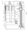
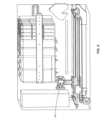
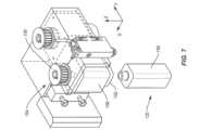
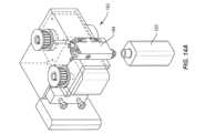
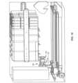
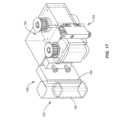
一実施形態では、本開示は、エアロゾル前駆体組成物を混合および分配するためのユニットを含む。ユニットは、複数のバルク材料充填ステーションを含み、複数のバルク材料充填ステーションは、エアロゾル形成剤を有する少なくとも1つの第1の充填ステーションと、エアロゾル前駆体を生成するための香味材料を有する少なくとも1つの第2の充填ステーションとを含む。ユニットは、エアロゾル前駆体を受け取るように構成された複数の容器を階層化するバルク消耗品パックをさらに含む。ユニットは、バルク消耗品パックから容器を取り出し、少なくとも2次元にわたって容器を移動させて複数のバルク材料充填ステーションのうちの少なくとも2つに停止するように構成されたロボットをさらに含む。In one embodiment, the present disclosure includes a unit for mixing and dispensing an aerosol precursor composition. The unit includes a plurality of bulk material filling stations, the plurality of bulk material filling stations including at least one first filling station having an aerosol former and at least one second filling station having a flavoring material for generating the aerosol precursor. The unit further includes a bulk consumable pack layering a plurality of containers configured to receive the aerosol precursor. The unit further includes a robot configured to retrieve a container from the bulk consumable pack and move the container across at least two dimensions to stop at at least two of the plurality of bulk material filling stations.
上記の混合および分配ユニットは、以下の記述からの特徴のうちの1つ以上を、個別に、ならびにそれらの組合せおよび順列でさらに含んでもよい。The above mixing and dispensing unit may further include one or more of the features from the following description, individually and in combinations and permutations thereof:
ユニットは、複数のバルク材料充填ステーションのうちの少なくとも2つで容器を充填する前に容器からキャップを取り外すように構成されたキャッピングステーションをさらに含む。キャッピングステーションはまた、容器にエアロゾル前駆体を少なくとも部分的に充填した後にキャップを取り付けるように構成されてもよい。The unit further includes a capping station configured to remove a cap from the container prior to filling the container at at least two of the plurality of bulk material filling stations. The capping station may also be configured to attach a cap after the container is at least partially filled with the aerosol precursor.
ユニットは、容器内のエアロゾル前駆体の量を測定するように構成された検査ステーションをさらに含んでもよい。The unit may further include an inspection station configured to measure the amount of aerosol precursor in the container.
ユニットは、香味材料に基づいて標識を提供するように構成されたラベル付けステーションをさらに含んでもよい。ラベル付けステーションは、容器にウェブを付けることにより標識を提供してもよい。ラベル付けステーションは、標識を形成するための印刷ヘッドを含んでもよい。The unit may further include a labeling station configured to provide an indicia based on the flavor material. The labeling station may provide the indicia by applying a web to the container. The labeling station may include a print head for forming the indicia.
ユニットの各バルク材料充填ステーションは、ポンプを含んでもよい。ポンプがリザーバに一体化されて、バルク材料充填ステーションから取り外し可能なバルク材料パックを形成してもよい。ポンプは、リザーバと連通する階層化チャンバを含んでもよく、階層化チャンバは、それぞれのバルク材料の測定された用量を保持するように構成される。RFIDアンテナがロボットのステージに取り付けられてもよく、RFIDアンテナは、バルク材料パック上のRFIDタグを読み取るように構成される。ポンプは、ポンプの各作動時にそれぞれのバルク材料の測定された用量を分配するように構成されてもよい。ポンプは、ロボットまたは容器の一部によって押圧されることにより作動してもよい。Each bulk material filling station of the unit may include a pump. The pump may be integrated with a reservoir to form a bulk material pack that is removable from the bulk material filling station. The pump may include a layering chamber in communication with the reservoir, the layering chamber configured to hold a measured dose of the respective bulk material. An RFID antenna may be attached to a stage of the robot, the RFID antenna configured to read an RFID tag on the bulk material pack. The pump may be configured to dispense a measured dose of the respective bulk material upon each actuation of the pump. The pump may be actuated by being pressed by a portion of the robot or a container.
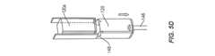
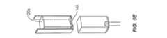
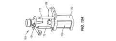
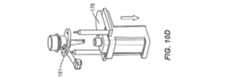
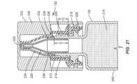
ユニットは、チャイルドレジスタンス機能および不正開封防止機能を含む容器を使用してもよい。各容器は、エアロゾル前駆体を保持するための貯蔵容積と、キャップとを有するボトルを含んでもよい。キャップは、ノズルと、不正開封防止バンドを含む内側カバーと、内側カバー上に設けられた外側カバーとを含んでもよい。外側カバーは、ボトルから内側カバーを取り外す能力を制限するチャイルドレジスタンス機能をもたらす。第1の状態では、ノズル、内側カバーおよび外側カバーはボトルから同時に取り外すことができる。第2の状態では、ノズルは、ボトルに実質的に恒久的に固定されている。さらに、ボトルは、雄ねじを含む首部を有してもよい。ノズルは、首部内に少なくとも部分的にはまるように構成されてもよく、ノズルは、ボトルからエアロゾル前駆体を分配するための開口部を有する。内側カバーは、首部の雄ねじと係合するための雌ねじをさらに含んでもよく、不正開封防止バンドは、内側カバーの内部に配置されてもよい。第1の状態では、ノズルが第1の挿入距離I1だけ首部に挿入され、内側カバーが第1のねじ距離T1だけ首部と螺合するように、キャップがボトルと係合してもよい。第2の状態では、ノズルがI1よりも大きい第2の挿入距離I2だけ首部に挿入され、内側カバーがT1よりも大きい第2のねじ距離T2だけ首部と螺合するように、キャップがボトルと係合してもよい。第3の状態では、ノズルは、第2の挿入距離I2だけ首部に挿入されてもよく、ノズルの開口部からボトル内のエアロゾル前駆体を分配することができるように、内側カバーは、首部と螺合しない。第4の状態では、キャップがボトルから取り外されて、貯蔵容積にエアロゾル前駆体を少なくとも部分的に充填することが可能になる。The unit may use containers that include child-resistant and tamper-resistant features. Each container may include a bottle having a storage volume for holding the aerosol precursor and a cap. The cap may include a nozzle, an inner cover including a tamper-resistant band, and an outer cover provided on the inner cover. The outer cover provides a child-resistant feature that limits the ability to remove the inner cover from the bottle. In a first state, the nozzle, the inner cover, and the outer cover can be simultaneously removed from the bottle. In a second state, the nozzle is substantially permanently fixed to the bottle. Additionally, the bottle may have a neck that includes male threads. The nozzle may be configured to fit at least partially within the neck, the nozzle having an opening for dispensing the aerosol precursor from the bottle. The inner cover may further include female threads for engaging with the male threads of the neck, and the tamper-resistant band may be disposed within the interior of the inner cover. In the first state, the cap may engage the bottle such that the nozzle is inserted into the neck a first insertion distance I1 and the inner cover is threaded with the neck a first thread distance T1. In a second state, the cap may be engaged with the bottle such that the nozzle is inserted into the neck a second insertion distance I2 greater than I1 and the inner cover is threaded with the neck a second thread distance T2 greater than T1. In a third state, the nozzle may be inserted into the neck a second insertion distance I2 and the inner cover is not threaded with the neck such that the aerosol precursor in the bottle can be dispensed from the nozzle opening. In a fourth state, the cap is removed from the bottle to allow the storage volume to be at least partially filled with the aerosol precursor.
ノズルは、ノズルが内側カバーとともにボトルから取り外されるように、内側カバーにスナップ嵌めするための戻り止めをさらに含んでもよい。ボトルの首部は半径方向フランジをさらに含んでもよく、第1の状態では不正開封防止バンドは作動せず、第2の状態では、不正開封防止バンドは、半径方向フランジの下に配置されることによって作動し、それにより、第3の状態を達成するために内側カバーが取り外されると、バンドが半径方向フランジを通過する際にバンドがダメージを受ける。不正開封防止バンドは、第1の状態では半径方向フランジを押圧し得る。第2の状態では、内側カバーは、首部に形成されたボトル位置合わせストッパに当接してもよく、ボトル位置合わせストッパは、それぞれの側壁が円筒形でない場合、第2の状態でボトルの側壁とキャップの側壁との位置合わせを容易にする。The nozzle may further include a detent for snapping onto the inner cover so that the nozzle may be removed from the bottle together with the inner cover. The neck of the bottle may further include a radial flange, where in a first state the tamper-evident band is not activated and in a second state the tamper-evident band is activated by being placed under the radial flange, whereby when the inner cover is removed to achieve the third state the band is damaged as it passes over the radial flange. The tamper-evident band may press against the radial flange in the first state. In the second state the inner cover may abut against a bottle alignment stopper formed on the neck, which facilitates alignment of the sidewalls of the bottle and the sidewalls of the cap in the second state if the respective sidewalls are not cylindrical.
一実施形態では、ボトルの貯蔵容積は、少なくとも約5mlであり、好ましくは少なくとも約15mlである。In one embodiment, the bottle has a storage volume of at least about 5 ml, preferably at least about 15 ml.
混合および分配ユニットはまた、ニコチン、メントール、フルーツ香味、フローラル香味およびセイボリー香味のいずれかから選択されるバルク材料をそれぞれ有する複数の第2のバルク材料充填ステーションを含んでもよい。ロボットは、容器ホルダ、第1の次元ガイドおよび第2の次元ガイドを含んでもよい。ユーザインターフェースは、複数のバルク材料ステーションのいずれにロボットが停止するかを指示する選択情報を受信するように構成されてもよい。ロボットを制御して、所望のバルク材料充填ステーションに停止させ、各バルク材料充填ステーションから所望の量のバルク材料を分配するために、プロセッサを有するコントローラが提供されてもよい。The mixing and dispensing unit may also include a plurality of second bulk material filling stations each having a bulk material selected from any of nicotine, menthol, fruit flavor, floral flavor, and savory flavor. The robot may include a container holder, a first dimensional guide, and a second dimensional guide. The user interface may be configured to receive selection information indicating at which of the plurality of bulk material stations the robot will stop. A controller having a processor may be provided to control the robot to stop at a desired bulk material filling station and dispense a desired amount of bulk material from each bulk material filling station.
他の実施形態では、本開示は、エアロゾル前駆体のカスタム組成物を作製する自動化された方法を提示する。一実施形態による方法は、ロボットによって容器を取り出すことと、第1のポンプによって第1の位置でエアロゾル形成剤を容器に分配することと、ロボットによって第2の位置に容器を移動させることと、第2のポンプによって第2の位置で少なくとも1つの香味材料を容器に分配することと、容器にキャップを施すことと、エアロゾル形成剤と少なくとも1つの香味材料とを混合することとを含む。In another embodiment, the present disclosure presents an automated method of making a custom composition of an aerosol precursor. The method according to one embodiment includes retrieving a container by a robot, dispensing an aerosol forming agent into the container at a first location by a first pump, moving the container to a second location by the robot, dispensing at least one flavoring material into the container at the second location by a second pump, capping the container, and mixing the aerosol forming agent with the at least one flavoring material.
エアロゾル前駆体のカスタム組成物の作製方法は、以下の任意の特徴のうちの1つ以上を個別に、またはそれらの組合せで含んでもよい。The method for making a custom composition of an aerosol precursor may include any one or more of the following features, either individually or in combination:
容器を取り出す工程は、吸引を使用して、複数の空の容器を含むバルク消耗品パックから容器を引っ張ることを含んでもよい。The step of removing the container may include using suction to pull the container from a bulk consumable pack that includes a plurality of empty containers.
液体エアロゾル形成剤を分配する工程は、液体エアロゾル形成剤用のリザーバに一体化された第1のポンプを作動させることを含んでもよい。第1のポンプを作動させることは、第1のポンプの一部を実質的に垂直に上方に押すことを含んでもよい。押す行為は、その中に保持された容器のボトルを有する容器ホルダと第1のポンプの一部とを接触させることと、第1のポンプに対して容器ホルダを持ち上げることとを含んでもよい。また、第1のポンプの作動によって、第1のポンプ上のドリップガードが容器ホルダとともに移動してもよい。The step of dispensing the liquid aerosol forming agent may include actuating a first pump integrated into a reservoir for the liquid aerosol forming agent. Actuating the first pump may include pushing a portion of the first pump substantially vertically upward. The act of pushing may include contacting a portion of the first pump with a container holder having a container bottle held therein and lifting the container holder relative to the first pump. Actuation of the first pump may also cause a drip guard on the first pump to move with the container holder.
容器にキャップを施す工程は、ボトルにキャップを取り付けることを含んでもよい。方法は、液体エアロゾル形成剤を容器に分配する前にボトルからキャップを取り外すことをさらに含んでもよい。キャップを取り外す工程は、キャップを保持することと、ボトルに対してキャップを回転させることとを含んでもよい。The step of capping the container may include attaching the cap to the bottle. The method may further include removing the cap from the bottle prior to dispensing the liquid aerosol forming agent into the container. The step of removing the cap may include holding the cap and rotating the cap relative to the bottle.
混合する工程は、同じロボットを使用して、容器を螺旋パターンの平面に沿って移動させることと、および/または容器を貫通する軸の周りで容器を回転させることとを含んでもよい。混合は、容器を平面外に移動させることをさらに含んでもよい。The mixing step may include using the same robot to move the container along a plane in a spiral pattern and/or to rotate the container about an axis passing through the container. The mixing may further include moving the container out of plane.
作製方法はまた、容器内のエアロゾル前駆体の量を測定することを含んでもよい。エアロゾル前駆体の量を測定することは、距離計を使用して、距離計とエアロゾル前駆体の表面との間の距離を測定することを含んでもよい。方法は、エアロゾル前駆体の量が所定の範囲外である場合に、容器を廃棄物入れに移動させることを伴ってもよい。The method of making may also include measuring the amount of aerosol precursor in the container. Measuring the amount of aerosol precursor may include using a range finder to measure a distance between a range finder and a surface of the aerosol precursor. The method may involve moving the container to a waste bin if the amount of aerosol precursor is outside a predetermined range.
作製方法はまた、容器にラベルを付けることを含んでもよい。容器にラベルを付けることは、容器上にフィルムを追加することを含んでもよい。ラベルを付けることは、フィルムに情報を印刷することをさらに含んでもよい。容器にラベルを付けることは、容器に情報を印刷することを含んでもよい。The method of making may also include labeling the container. Labeling the container may include adding a film onto the container. Labeling may further include printing information onto the film. Labeling the container may include printing information onto the container.
作製方法はまた、少なくとも1つの香味材料を容器に分配する前に少なくとも1つの香味材料を検証することを含んでもよく、検証する工程はRFIDを使用することを含む。The method of making may also include verifying the at least one flavor ingredient prior to dispensing the at least one flavor ingredient into the container, the verifying step including using an RFID.
本開示の追加の実施形態は、チャイルドレジスタンス不正開封防止容器を提供する。容器は、液体内容物を保持するための貯蔵容積を有するボトルとキャップとを含む。キャップは、ノズルと、不正開封防止バンドを含む内側カバーと、内側カバー上に設けられた外側カバーとを含み、外側カバーは、ボトルから内側カバーを取り外す能力を制限するチャイルドレジスタンス機能をもたらす。第1の状態では、ノズル、内側カバーおよび外側カバーはボトルから同時に取り外すことができる。第2の状態では、ノズルはボトルに実質的に恒久的に固定されている。An additional embodiment of the present disclosure provides a child-resistant tamper-evident container. The container includes a bottle having a storage volume for holding liquid contents and a cap. The cap includes a nozzle, an inner cover including a tamper-evident band, and an outer cover disposed on the inner cover, the outer cover providing a child-resistant feature that limits the ability to remove the inner cover from the bottle. In a first state, the nozzle, the inner cover, and the outer cover can be simultaneously removed from the bottle. In a second state, the nozzle is substantially permanently secured to the bottle.
チャイルドレジスタンス不正開封防止容器の実施形態は、場合により、以下の特徴のうちの1つ以上を個別に、またはそれらの様々な組合せでさらに含んでもよい。ボトルは、雄ねじを含む首部を有してもよい。ノズルは、首部内に少なくとも部分的にはまるように構成されてもよく、ノズルは、ボトルから液体内容物を分配するための開口部を有する。内側カバーは、首部の雄ねじと係合するための雌ねじをさらに含んでもよく、不正開封防止バンドは内側カバーの内部に配置されてもよい。第1の状態では、ノズルが第1の挿入距離I1だけ首部に挿入され、内側カバーが第1のねじ距離T1だけ首部と螺合するように、キャップがボトルと係合してもよい。第2の状態では、ノズルがI1よりも大きい第2の挿入距離I2だけ首部に挿入され、内側カバーがT1よりも大きい第2のねじ距離T2だけ首部と螺合するように、キャップがボトルと係合してもよい。第3の状態では、ノズルは第2の挿入距離I2だけ首部に挿入されてもよく、ノズルの開口部からボトルの液体内容物を分配することができるように内側カバーは首部と螺合しない。第4の状態では、キャップがボトルから取り外されて、貯蔵容積に液体内容物を少なくとも部分的に充填することが可能になる。Embodiments of the child-resistant tamper-evident container may optionally further include one or more of the following features, individually or in various combinations thereof. The bottle may have a neck including male threads. The nozzle may be configured to fit at least partially within the neck, the nozzle having an opening for dispensing liquid contents from the bottle. The inner cover may further include female threads for engaging with the male threads of the neck, and the tamper-evident band may be disposed within the inner cover. In a first state, the cap may engage the bottle such that the nozzle is inserted into the neck a first insertion distance I1 and the inner cover threads with the neck a first thread distance T1. In a second state, the cap may engage the bottle such that the nozzle is inserted into the neck a second insertion distance I2 greater than I1 and the inner cover threads with the neck a second thread distance T2 greater than T1. In a third state, the nozzle may be inserted into the neck a second insertion distance I2, and the inner cover does not thread onto the neck to allow the liquid contents of the bottle to be dispensed from the nozzle opening. In a fourth state, the cap is removed from the bottle to allow the storage volume to be at least partially filled with the liquid contents.
ノズルは、ノズルが内側カバーとともにボトルから取り外されるように、内側カバーにスナップ嵌めするための戻り止めを含んでもよい。首部は、半径方向フランジをさらに含んでもよい。第1の状態では、不正開封防止バンドは作動しない。第2の状態では、不正開封防止バンドは、半径方向フランジの下に配置されることによって作動し、それにより、第3の状態を達成するために内側カバーが取り外されると、バンドが半径方向フランジを通過する際にバンドがダメージを受ける。不正開封防止バンドは、第1の状態では半径方向フランジを押圧し得る。The nozzle may include a detent for snapping onto the inner cover such that the nozzle is removed from the bottle along with the inner cover. The neck may further include a radial flange. In the first state, the tamper-evident band is not activated. In the second state, the tamper-evident band is activated by being placed under the radial flange such that when the inner cover is removed to achieve the third state, the band is damaged as it passes over the radial flange. The tamper-evident band may press against the radial flange in the first state.
第2の状態では、内側カバーは、首部に形成されたボトル位置合わせストッパに当接してもよく、位置合わせストッパは、それぞれの側壁が円筒形でない場合、第2の状態でボトルの側壁とキャップの側壁との位置合わせを容易にする。In the second state, the inner cover may abut against a bottle alignment stopper formed on the neck, which facilitates alignment of the bottle sidewall with the cap sidewall in the second state if the respective sidewalls are not cylindrical.
ボトルの貯蔵容積は、少なくとも約5ml、好ましくは少なくとも約15mlであってよい。The bottle's storage volume may be at least about 5 ml, preferably at least about 15 ml.
本開示のさらに他の実施形態は、容器にエアロゾル前駆体を充填する方法を含む。そのような方法の1つは、機械によってボトルからキャップを分離することを含み、キャップは、ノズル、内側カバーおよび外側カバーを含む。方法は、各ステーションがエアロゾル前駆体の液体成分を含む複数の充填ステーションから、ボトルの貯蔵容積にエアロゾル前駆体を少なくとも部分的に充填することと、ノズルがボトルに実質的に恒久的に固定され、内側カバーとともに形成された不正開封防止バンドがボトルの首部から延びる半径方向フランジの下で作動するように、ボトルにキャップを取り付けることとをさらに含む。Still other embodiments of the present disclosure include methods of filling a container with an aerosol precursor. One such method includes separating a cap from a bottle by a machine, the cap including a nozzle, an inner cover, and an outer cover. The method further includes at least partially filling a storage volume of the bottle with the aerosol precursor from a plurality of filling stations, each station including a liquid component of the aerosol precursor, and attaching the cap to the bottle such that the nozzle is substantially permanently fixed to the bottle and a tamper-evident band formed with the inner cover operates under a radial flange extending from the neck of the bottle.
容器を充填する方法はまた、以下の特徴および要素のうちの1つ以上を個別に、またはそれらの様々な組合せで含んでもよい。ボトルからキャップを分離する工程は、ボトルに対してキャップを回転させることを少なくとも含んでもよい。ボトルからキャップを分離することはまた、内側カバーに対して外側カバーを圧迫することおよび押込むことのうちの少なくとも1つを含んでもよい。ボトルからキャップを分離することは、ボトルからノズル、内側カバーおよび外側カバーを同時に取り外すことを含んでもよい。The method of filling a container may also include one or more of the following features and elements, individually or in various combinations thereof: The step of separating the cap from the bottle may include at least rotating the cap relative to the bottle. Separating the cap from the bottle may also include at least one of squeezing and pushing the outer cover against the inner cover. Separating the cap from the bottle may include simultaneously removing the nozzle, the inner cover and the outer cover from the bottle.
ボトルにキャップを取り付ける工程は、ボトルに対してキャップを回転させることを含んでもよい。The step of attaching the cap to the bottle may include rotating the cap relative to the bottle.
容器を充填する方法はまた、ボトル位置合わせストッパがキャップ位置合わせストッパに当接するまで、ボトルに対してキャップを回転させることを含んでもよい。The method of filling the container may also include rotating the cap relative to the bottle until the bottle alignment stopper abuts the cap alignment stopper.
貯蔵容積を少なくとも部分的に充填する工程は、第1のポンプによって第1の位置で液体エアロゾル形成剤を容器に分配することと、ロボットによって第2の位置に容器を移動させることと、第2のポンプによって第2の位置で少なくとも1つの液体香味材料を容器に分配することとを含んでもよい。液体エアロゾル形成剤を分配することは、液体エアロゾル形成剤用のリザーバに一体化された第1のポンプを作動させることを含んでもよい。第1のポンプを作動させることは、第1のポンプの一部を実質的に垂直に上方に押すことを含んでもよい。押す行為は、その中に保持された容器のボトルを有する容器ホルダと第1のポンプの一部とを接触させることと、第1のポンプに対して容器ホルダを持ち上げることとを含んでもよい。The step of at least partially filling the storage volume may include dispensing a liquid aerosol forming agent into the container at a first location by a first pump, moving the container to a second location by a robot, and dispensing at least one liquid flavoring material into the container at the second location by a second pump. Dispensing the liquid aerosol forming agent may include actuating a first pump integrated into a reservoir for the liquid aerosol forming agent. Actuating the first pump may include pushing a portion of the first pump substantially vertically upward. The act of pushing may include contacting a portion of the first pump with a container holder having a bottle of the container held therein, and lifting the container holder relative to the first pump.
容器を充填する方法はまた、少なくとも1つの液体香味材料を容器に分配する前に少なくとも1つの液体香味材料を検証することを含んでもよく、検証する工程はRFIDを使用することを含む。容器を充填する方法はまた、螺旋パターンの平面に沿って容器を移動させて、エアロゾル前駆体液体を混合することを含んでもよい。追加の工程はまた、容器内のエアロゾル前駆体の量を測定することと、エアロゾル前駆体の量が所定の範囲外である場合に容器を廃棄物入れに移動させることとを含んでもよい。The method of filling the container may also include verifying the at least one liquid flavoring material prior to dispensing the at least one liquid flavoring material into the container, the verifying step including using an RFID. The method of filling the container may also include moving the container along a plane of the spiral pattern to mix the aerosol precursor liquid. An additional step may also include measuring the amount of aerosol precursor in the container and moving the container to a waste receptacle if the amount of aerosol precursor is outside a predetermined range.
本開示は、限定するものではないが、以下の実施形態を含む。This disclosure includes, but is not limited to, the following embodiments:
実施形態1:エアロゾル前駆体組成物を混合および分配するユニットであって、ユニットは、
エアロゾル形成剤を有する少なくとも1つの第1の充填ステーションおよびエアロゾル前駆体を生成するための香味材料を有する少なくとも1つの第2の充填ステーションを含む複数のバルク材料充填ステーションと、
エアロゾル前駆体を受け取るように構成された複数の容器を階層化するバルク消耗品パックと、
バルク消耗品パックから容器を取り出し、少なくとも2次元にわたって容器を移動させて複数のバルク材料充填ステーションのうちの少なくとも2つに停止するように構成されたロボットと、
を含む、ユニット。 Embodiment 1: A unit for mixing and dispensing an aerosol precursor composition, the unit comprising:
a plurality of bulk material filling stations including at least one first filling station having an aerosol forming agent and at least one second filling station having a flavoring material for generating an aerosol precursor;
a bulk consumable pack layering a plurality of containers configured to receive an aerosol precursor;
a robot configured to retrieve a container from a bulk consumable pack and move the container across at least two dimensions to land at at least two of the plurality of bulk material loading stations;
Including, units.
実施形態2:複数のバルク材料充填ステーションのうちの少なくとも2つで容器を充填する前に容器からキャップを取り外すように構成され、容器にエアロゾル前駆体を充填した後にキャップを取り付けるように構成されたキャッピングステーションをさらに含む、任意の前述の実施形態のユニット。Embodiment 2: The unit of any preceding embodiment, further comprising a capping station configured to remove caps from containers prior to filling the containers in at least two of the plurality of bulk material filling stations and configured to attach caps after filling the containers with the aerosol precursor.
実施形態3:容器内のエアロゾル前駆体の量を測定するように構成された検査ステーションをさらに含む、任意の前述の実施形態のユニット。Embodiment 3: The unit of any preceding embodiment, further comprising an inspection station configured to measure the amount of aerosol precursor in the container.
実施形態4:香味材料に基づいて標識を提供するように構成されたラベル付けステーションをさらに含む、任意の前述の実施形態のユニット。Embodiment 4: The unit of any preceding embodiment, further comprising a labeling station configured to provide a label based on a flavor material.
実施形態5:各バルク材料充填ステーションがポンプを含む、任意の前述の実施形態のユニット。Embodiment 5: A unit of any preceding embodiment, wherein each bulk material filling station includes a pump.
実施形態6:ポンプがリザーバに一体化されて、バルク材料充填ステーションから取り外し可能なバルク材料パックを形成する、任意の前述の実施形態のユニット。Embodiment 6: The unit of any preceding embodiment, in which a pump is integrated into the reservoir to form a bulk material pack that is removable from the bulk material filling station.
実施形態7:ポンプが、リザーバと連通する階層化チャンバを含み、階層化チャンバが、それぞれのバルク材料の測定された用量を保持するように構成される、任意の前述の実施形態のユニット。Embodiment 7: The unit of any preceding embodiment, wherein the pump includes layered chambers in communication with the reservoir, the layered chambers configured to hold measured doses of respective bulk materials.
実施形態8:ロボットのステージに取り付けられたRFIDアンテナをさらに含み、RFIDアンテナが、バルク材料パック上のRFIDタグを読み取るように構成される、任意の前述の実施形態のユニット。Embodiment 8: The unit of any preceding embodiment, further comprising an RFID antenna attached to the stage of the robot, the RFID antenna configured to read an RFID tag on the bulk material pack.
実施形態9:ポンプが、ポンプの各作動時にそれぞれのバルク材料の測定された用量を分配するように構成される、任意の前述の実施形態のユニット。Embodiment 9: The unit of any preceding embodiment, wherein the pump is configured to dispense a measured dose of the respective bulk material upon each actuation of the pump.
実施形態10:ポンプが、ロボットまたは容器の一部によって押圧されることにより作動する、任意の前述の実施形態のユニット。Embodiment 10: A unit of any preceding embodiment, in which the pump is actuated by being pressed by a part of the robot or container.
実施形態11:各容器が、チャイルドレジスタンス機能および不正開封防止機能を含む、任意の前述の実施形態のユニット。Embodiment 11: A unit of any preceding embodiment, wherein each container includes child-resistant and tamper-evident features.
実施形態12:各容器が、エアロゾル前駆体を保持するための貯蔵容積を有するボトルと、キャップと、を含み、キャップが、ノズルと、不正開封防止バンドを含む内側カバーと、内側カバー上に設けられた外側カバーと、を含み、外側カバーが、ボトルから内側カバーを取り外す能力を制限するチャイルドレジスタンス機能をもたらし、第1の状態では、ノズル、内側カバーおよび外側カバーはボトルから同時に取り外すことができ、第2の状態では、ノズルがボトルに実質的に恒久的に固定されている、任意の前述の実施形態のユニット。Embodiment 12: A unit of any preceding embodiment, wherein each container comprises a bottle having a storage volume for holding an aerosol precursor, and a cap, the cap comprising a nozzle, an inner cover including a tamper-evident band, and an outer cover provided on the inner cover, the outer cover providing a child-resistant feature that limits the ability to remove the inner cover from the bottle, and wherein in a first state, the nozzle, the inner cover and the outer cover can be simultaneously removed from the bottle, and in a second state, the nozzle is substantially permanently fixed to the bottle.
実施形態13:ボトルが雄ねじを含む首部を有し、ノズルが、首部内に少なくとも部分的にはまるように構成され、ノズルが、ボトルからエアロゾル前駆体を分配するための開口部を有し、内側カバーが、首部の雄ねじと係合するための雌ねじをさらに含み、不正開封防止バンドが内側カバーの内部に配置される、任意の前述の実施形態のユニット。Embodiment 13: The unit of any preceding embodiment, wherein the bottle has a neck including male threads, the nozzle is configured to fit at least partially within the neck, the nozzle has an opening for dispensing the aerosol precursor from the bottle, the inner cover further includes female threads for engaging the male threads of the neck, and a tamper evident band is disposed inside the inner cover.
実施形態14:第1の状態では、ノズルが第1の挿入距離I1だけ首部に挿入され、内側カバーが第1のねじ距離T1だけ首部と螺合するように、キャップがボトルと係合し、第2の状態では、ノズルがI1よりも大きい第2の挿入距離I2だけ首部に挿入され、内側カバーがT1よりも大きい第2のねじ距離T2だけ首部と螺合するように、キャップがボトルと係合し、第3の状態では、ノズルが第2の挿入距離I2だけ首部に挿入され、ノズルの開口部からボトル内のエアロゾル前駆体を分配することができるように内側カバーが首部と螺合しない、任意の前述の実施形態のユニット。Embodiment 14: The unit of any preceding embodiment, wherein in a first state, the nozzle is inserted into the neck a first insertion distance I1 and the cap engages with the bottle such that the inner cover threads with the neck a first thread distance T1, in a second state, the nozzle is inserted into the neck a second insertion distance I2 greater than I1 and the cap engages with the bottle such that the inner cover threads with the neck a second thread distance T2 greater than T1, and in a third state, the nozzle is inserted into the neck a second insertion distance I2 and the inner cover does not thread with the neck such that the aerosol precursor in the bottle can be dispensed from the nozzle opening.
実施形態15:第4の状態をさらに含み、第4の状態では、キャップがボトルから取り外されて、貯蔵容積にエアロゾル前駆体を少なくとも部分的に充填することが可能になる、任意の前述の実施形態のユニット。Embodiment 15: The unit of any preceding embodiment, further comprising a fourth state, in which the cap is removed from the bottle to allow the storage volume to be at least partially filled with the aerosol precursor.
実施形態16:ノズルが内側カバーとともにボトルから取り外されるように、ノズルが、内側カバーにスナップ嵌めするための戻り止めを含む、任意の前述の実施形態のユニット。Embodiment 16: The unit of any preceding embodiment, wherein the nozzle includes a detent for snapping onto the inner cover so that the nozzle can be removed from the bottle along with the inner cover.
実施形態17:首部が半径方向フランジをさらに含み、第1の状態では不正開封防止バンドは作動せず、第2の状態では、不正開封防止バンドが半径方向フランジの下に配置されることによって作動し、それにより、第3の状態を達成するために内側カバーが取り外されると、バンドが半径方向フランジを通過する際にバンドがダメージを受ける、任意の前述の実施形態のユニット。Embodiment 17: The unit of any preceding embodiment, wherein the neck further includes a radial flange, and wherein in a first state the tamper-evident band is not activated and in a second state the tamper-evident band is activated by being placed under the radial flange, such that when the inner cover is removed to achieve a third state, the band is damaged as it passes over the radial flange.
実施形態18:第2の状態では、内側カバーが、首部に形成されたボトル位置合わせストッパに当接し、ボトル位置合わせストッパが、それぞれの側壁が円筒形でない場合、第2の状態でボトルの側壁とキャップの側壁との位置合わせを容易にする、任意の前述の実施形態のユニット。Embodiment 18: The unit of any preceding embodiment, wherein in the second state, the inner cover abuts against a bottle alignment stopper formed on the neck, the bottle alignment stopper facilitating alignment of the sidewall of the bottle with the sidewall of the cap in the second state if the respective sidewalls are not cylindrical.
実施形態19:ニコチン、メントール、フルーツ香味、フローラル香味およびセイボリー香味のいずれかから選択されるバルク材料をそれぞれ有する複数の第2のバルク材料充填ステーションを含む、任意の前述の実施形態のユニット。Embodiment 19: The unit of any preceding embodiment, including a plurality of second bulk material filling stations, each having a bulk material selected from any of nicotine, menthol, fruit flavors, floral flavors, and savory flavors.
実施形態20:複数のバルク材料ステーションのいずれにロボットが停止するかを指示する選択情報を受信するように構成されたユーザインターフェースをさらに含む、任意の前述の実施形態のユニット。Embodiment 20: The unit of any preceding embodiment, further comprising a user interface configured to receive selection information indicating at which of a plurality of bulk material stations the robot is to stop.
実施形態21:ロボットを制御して、所望のバルク材料充填ステーションに停止させ、各バルク材料充填ステーションから所望の量のバルク材料を分配するために、プロセッサを有するコントローラをさらに含む、任意の前述の実施形態のユニット。Embodiment 21: The unit of any preceding embodiment, further including a controller having a processor for controlling the robot to stop at desired bulk material filling stations and dispense a desired amount of bulk material from each bulk material filling station.
実施形態22:エアロゾル前駆体のカスタム組成物を作製する自動化された方法であって、方法が、
ロボットによって容器を取り出すことと、
第1のポンプによって第1の位置でエアロゾル形成剤を容器に分配することと、
ロボットによって第2の位置に容器を移動させることと、
第2のポンプによって第2の位置で少なくとも1つの香味材料を容器に分配することと、
容器にキャップを施すことと、
エアロゾル形成剤と少なくとも1つの香味材料とを混合することと、
を含む、方法。 Embodiment 22: An automated method for making a custom composition of an aerosol precursor, the method comprising:
removing the container by the robot;
Dispensing an aerosol forming agent into a container at a first location with a first pump;
moving the container to a second location by the robot;
dispensing at least one flavor material into the container at a second location with a second pump;
Cap the container;
mixing an aerosol forming agent with at least one flavor material;
A method comprising:
実施形態23:容器を取り出すことが、吸引を使用して、複数の空の容器を含むバルク消耗品パックから容器を引っ張ることを含む、任意の前述の実施形態の方法。Embodiment 23: The method of any preceding embodiment, wherein removing the container includes using suction to pull the container from a bulk consumable pack that includes a plurality of empty containers.
実施形態24:液体エアロゾル形成剤を分配することが、液体エアロゾル形成剤用のリザーバに一体化された第1のポンプを作動させることを含む、任意の前述の実施形態の方法。Embodiment 24: The method of any preceding embodiment, wherein dispensing the liquid aerosol forming agent includes actuating a first pump integrated into a reservoir for the liquid aerosol forming agent.
実施形態25:容器にキャップを施すことが、ボトルにキャップを取り付けることを含み、液体エアロゾル形成剤を容器に分配する前にボトルからキャップを取り外すことをさらに含む、任意の前述の実施形態の方法。Embodiment 25: The method of any preceding embodiment, wherein capping the container comprises attaching a cap to a bottle and further comprises removing the cap from the bottle prior to dispensing the liquid aerosol forming agent into the container.
実施形態26:混合することが、容器を螺旋パターンの平面に沿って移動させることを含む、任意の前述の実施形態の方法。Embodiment 26: The method of any preceding embodiment, wherein mixing comprises moving the container along a plane in a spiral pattern.
実施形態27:混合することが、容器を貫通する軸の周りで容器を回転させることをさらに含む、任意の前述の実施形態の方法。Embodiment 27: The method of any preceding embodiment, wherein mixing further comprises rotating the container about an axis passing through the container.
実施形態28:容器を螺旋パターンで移動させることと、容器を回転させることとが、同じロボットを使用する、任意の前述の実施形態の方法。Embodiment 28: The method of any preceding embodiment, wherein moving the container in the spiral pattern and rotating the container use the same robot.
実施形態29:容器内のエアロゾル前駆体の量を測定することをさらに含む、任意の前述の実施形態の方法。Embodiment 29: The method of any preceding embodiment, further comprising measuring the amount of aerosol precursor in the container.
実施形態30:エアロゾル前駆体の量が所定の範囲外である場合に、容器を廃棄物入れに移動させることを含む、任意の前述の実施形態の方法。Embodiment 30: The method of any preceding embodiment, comprising removing the container to a waste bin if the amount of aerosol precursor is outside a predetermined range.
実施形態31:少なくとも1つの香味材料を容器に分配する前に少なくとも1つの香味材料を検証することをさらに含み、検証する工程がRFIDを使用することを含む、任意の前述の実施形態の方法。Embodiment 31: The method of any preceding embodiment, further comprising verifying the at least one flavor ingredient prior to dispensing the at least one flavor ingredient into the container, the verifying step comprising using an RFID.
実施形態32:チャイルドレジスタンス不正開封防止容器であって、
容器が、液体内容物を保持するための貯蔵容積を有するボトルと、キャップとを含み、キャップが、ノズルと、不正開封防止バンドを含む内側カバーと、内側カバー上に設けられた外側カバーと、を含み、外側カバーが、ボトルから内側カバーを取り外す能力を制限するチャイルドレジスタンス機能をもたらし、第1の状態では、ノズル、内側カバーおよび外側カバーは、ボトルから同時に取り外すことができ、第2の状態では、ノズルがボトルに実質的に恒久的に固定されている、チャイルドレジスタンス不正開封防止容器。 Embodiment 32: A child-resistant, tamper-evident container comprising:
1. A child-resistant, tamper-evident container, wherein the container comprises a bottle having a storage volume for holding liquid contents, and a cap, the cap comprising a nozzle, an inner cover including a tamper-evident band, and an outer cover disposed over the inner cover, the outer cover providing a child-resistant feature that limits the ability to remove the inner cover from the bottle, wherein in a first state, the nozzle, the inner cover and the outer cover can be simultaneously removed from the bottle, and in a second state, the nozzle is substantially permanently secured to the bottle.
実施形態33:ボトルが雄ねじを含む首部を有し、ノズルが、首部内に少なくとも部分的にはまるように構成され、ノズルが、ボトルから液体内容物を分配するための開口部を有し、内側カバーが、首部の雄ねじと係合するための雌ねじをさらに含み、不正開封防止バンドが内側カバーの内部に配置される、任意の前述の実施形態の容器。Embodiment 33: The container of any preceding embodiment, wherein the bottle has a neck including male threads, the nozzle is configured to fit at least partially within the neck, the nozzle has an opening for dispensing liquid contents from the bottle, the inner cover further includes female threads for engaging the male threads of the neck, and a tamper evident band is disposed inside the inner cover.
実施形態34:第1の状態では、ノズルが第1の挿入距離I1だけ首部に挿入され、内側カバーが第1のねじ距離T1だけ首部と螺合するように、キャップがボトルと係合し、第2の状態では、ノズルがI1よりも大きい第2の挿入距離I2だけ首部に挿入され、内側カバーがT1よりも大きい第2のねじ距離T2だけ首部と螺合するように、キャップがボトルと係合し、第3の状態では、ノズルが第2の挿入距離I2だけ首部に挿入され、ノズルの開口部からボトルの液体内容物を分配することができるように内側カバーが首部と螺合しない、任意の前述の実施形態の容器。Embodiment 34: A container of any preceding embodiment, wherein in a first state, the cap engages the bottle such that the nozzle is inserted into the neck a first insertion distance I1 and the inner cover threads onto the neck a first thread distance T1, in a second state, the cap engages the bottle such that the nozzle is inserted into the neck a second insertion distance I2 greater than I1 and the inner cover threads onto the neck a second thread distance T2 greater than T1, and in a third state, the nozzle is inserted into the neck the second insertion distance I2 and the inner cover does not thread onto the neck such that the liquid contents of the bottle can be dispensed from the opening of the nozzle.
実施形態35:容器にエアロゾル前駆体を充填する方法であって、
機械によってボトルから、ノズル、内側カバーおよび外側カバーを含むキャップを分離することと、
各ステーションがエアロゾル前駆体の液体成分を含む複数の充填ステーションから、ボトルの貯蔵容積にエアロゾル前駆体を少なくとも部分的に充填することと、
ノズルがボトルに実質的に恒久的に固定され、内側カバーとともに形成された不正開封防止バンドがボトルの首部から延びる半径方向フランジの下で作動するように、ボトルにキャップを取り付けることと、
を含む、方法。 Embodiment 35: A method of filling a container with an aerosol precursor, comprising the steps of:
separating the cap, including the nozzle, the inner cover and the outer cover, from the bottle by the machine;
at least partially filling a storage volume of the bottle with an aerosol precursor from a plurality of filling stations, each station containing a liquid component of the aerosol precursor;
attaching a cap to the bottle such that the nozzle is substantially permanently secured to the bottle and a tamper evident band formed with the inner cover operates beneath a radial flange extending from the neck of the bottle;
A method comprising:
実施形態36:ボトルからキャップを分離することが、ボトルからノズル、内側カバーおよび外側カバーを同時に取り外すことを含む、任意の前述の実施形態の方法。Embodiment 36: The method of any preceding embodiment, wherein separating the cap from the bottle includes simultaneously removing the nozzle, inner cover and outer cover from the bottle.
本開示のこれらならびに他の特徴、態様および利点は、以下に簡単に説明する添付の図面とともに、以下の詳細な説明を読むことにより明らかになるであろう。本開示は、そのような特徴または要素が本明細書の特定の実施形態の説明において明示的に組み合わされているかどうかにかかわらず、2つ、3つ、4つまたはそれ以上の上述の実施形態の任意の組合せ、ならびに本開示に記載の任意の2つ、3つ、4つまたはそれ以上の特徴または要素の組合せを含む。本開示は、前後関係が他に明確に指示されない限り、その様々な態様および実施形態のいずれかにおいて、開示の任意の分離可能な特徴または要素が、組合せ可能であるように意図された通りに見えるように全体的に読み取られることを意図している。These and other features, aspects and advantages of the present disclosure will become apparent from a reading of the following detailed description in conjunction with the accompanying drawings, which are briefly described below. The present disclosure includes any combination of two, three, four or more of the above-described embodiments, as well as any combination of two, three, four or more features or elements described in the present disclosure, regardless of whether such features or elements are expressly combined in the description of a particular embodiment herein. The present disclosure is intended to be read as a whole such that any separable features or elements of the disclosure, in any of its various aspects and embodiments, appear as intended to be combinable, unless the context clearly dictates otherwise.
本開示は上述の一般的な用語で記載しており、添付の図面をこれから参照するが、これらの図面は必ずしも縮尺通りに描かれていない。The present disclosure having been described in general terms above, reference will now be made to the accompanying drawings, which are not necessarily drawn to scale.
本開示は、以下、その例示的な実施形態を参照して、さらに詳細に記載される。これらの例示的な実施形態は、本開示が徹底的かつ完全であり、本開示の範囲を当業者に完全に伝えるように記載される。実際、本開示は、多くの異なる形態で具体化されてもよく、本明細書に記載の実施形態に限定されると解釈されるべきではない。むしろ、これらの実施形態は、本開示が、適用される法的要件を満たすように提供される。本明細書および添付の特許請求の範囲で使用される単数形「a」、「an」、「the」は、前後関係が他に明確に指示されない限り、複数の指示対象を含む。The present disclosure will now be described in further detail with reference to exemplary embodiments thereof. These exemplary embodiments are provided so that this disclosure will be thorough and complete, and will fully convey the scope of the disclosure to those skilled in the art. Indeed, the disclosure may be embodied in many different forms and should not be construed as limited to the embodiments set forth herein. Rather, these embodiments are provided so that this disclosure will satisfy applicable legal requirements. As used in this specification and the appended claims, the singular forms "a," "an," and "the" include plural referents unless the context clearly dictates otherwise.
以下に説明するように、本開示の実施形態は、エアロゾル前駆体組成物、エアロゾル前駆体組成物用であってエアロゾル前駆体組成物を収容する容器、エアロゾル前駆体の組成物を生成するための装置、および完成したエアロゾル前駆体組成物を内部に有する1つ以上の容器を排出するための装置に関する。また、以下に記載する物品および装置の機能から、関連する方法が説明され、理解される。エアロゾル前駆体(前駆体、エアロゾル前駆体組成物およびエアロゾル前駆体調合物とも区別なく呼ばれる)とは、エアロゾル送達装置と組み合わせて従来使用されている消費可能な液体組成物である。エアロゾル送達装置は一般に、電気エネルギーを使用してエアロゾル前駆体を加熱し、吸入可能な物質を形成する。エアロゾル送達装置は、その物品または装置のいかなる構成要素も実質的に燃焼することなく、紙巻タバコ、葉巻またはパイプを喫煙するという感覚の一部または全部(例えば、吸入および呼気の作法、味または香味の種類、感覚刺激効果、物理的感触、使用作法、目に見えるエアロゾルによってもたらされるような視覚的刺激など)を提供してもよい。As described below, embodiments of the present disclosure relate to aerosol precursor compositions, containers for aerosol precursor compositions that contain the aerosol precursor compositions, devices for generating the aerosol precursor compositions, and devices for discharging one or more containers with the finished aerosol precursor compositions therein. Related methods are also described and understood from the article and device functions described below. Aerosol precursors (also referred to interchangeably as precursors, aerosol precursor compositions, and aerosol precursor formulations) are consumable liquid compositions that are conventionally used in combination with aerosol delivery devices. Aerosol delivery devices generally use electrical energy to heat the aerosol precursor to form an inhalable substance. The aerosol delivery device may provide some or all of the sensation of smoking a cigarette, cigar, or pipe (e.g., the manner of inhalation and exhalation, the type of taste or flavor, the sensory stimulating effect, the physical feel, the manner of use, the visual stimuli such as those provided by a visible aerosol, etc.) without substantially burning any components of the article or device.
エアロゾル送達装置は一般に、多くの構成要素を含む。エアロゾル送達装置は、多くの場合、電源(すなわち、電力源)、少なくとも1つの制御構成要素(例えば、電源から物品の他の構成要素への電流の流れを制御することなどによって、発熱のための電力を作動、制御、調整および停止するための手段)、ヒータまたは発熱構成要素(例えば、一般に「噴霧器」と呼ばれる電気抵抗加熱要素または構成要素)、およびエアロゾル前駆体組成物(例えば、「スモークジュース」、「e-リキッド」および「e-ジュース」と一般に呼ばれる、一般に十分な熱を加えるとエアロゾルを生じることができる液体)、およびエアロゾル吸入のためにエアロゾル送達装置を吸引することを可能にするマウスエンド領域または先端(例えば、生成されたエアロゾルが吸引によりそこから引き出され得るように、物品を通る画定された空気流路)の何らかの組合せを含む。様々なエアロゾル送達装置の設計および構成要素の配置は、本開示に上記で組み込まれた代表的な製品など、開示されたまたは市販の電子エアロゾル送達装置を考慮して理解することができる。Aerosol delivery devices generally include many components. Aerosol delivery devices often include some combination of a power source (i.e., a power source), at least one control component (e.g., a means for activating, controlling, regulating, and deactivating power for heat generation, such as by controlling the flow of current from the power source to other components of the article), a heater or heat generating component (e.g., an electrical resistance heating element or component, commonly referred to as an "atomizer"), and an aerosol precursor composition (e.g., a liquid that can produce an aerosol upon application of sufficient heat, commonly referred to as "smoke juice," "e-liquid," and "e-juice"), and a mouth-end region or tip that allows the aerosol delivery device to be drawn upon for aerosol inhalation (e.g., a defined air flow path through the article so that the generated aerosol can be drawn therefrom by inhalation). The design and component arrangement of various aerosol delivery devices can be understood in view of the disclosed or commercially available electronic aerosol delivery devices, such as the representative products incorporated above in this disclosure.
図1を参照すると、本開示の実施形態は、ディスペンサユニット100に関する。一実施形態では、複数の種類で入手可能なカスタムブレンドエアロゾル前駆体組成物を内部に有する容器を排出するように、ディスペンサユニット100は、顧客または店員により操作される。少なくとも、ディスペンサユニット100から排出されるカスタムブレンドエアロゾル前駆体組成物は、少なくとも2種類、少なくとも3種類、少なくとも5種類、好ましくは10種類以上で入手可能である。利用可能な種類の数の上限は、ディスペンサユニット100の大きさ、および本開示のディスペンサユニットの実装時に使用される機器の何らかの技術的制限に関連し得る。香味および強度のうちの少なくとも1つが異なれば、エアロゾル前駆体組成物は異なる種類である。強度とは、ニコチン含有量または濃度を指し得る。強度とはまた、エアロゾル前駆体内の香味材料の濃度を指し得る。好ましくは、ディスペンサユニット100から排出されるカスタムブレンドエアロゾル前駆体組成物は、最初に別個の成分(例えば、本明細書でバルク材料と呼ばれるエアロゾル前駆体組成物成分)を組み合わせることにより、ディスペンサユニット100内でその場で生成される。一実施形態では、最初に分離された成分は、ディスペンサユニット100からユーザ(例えば、顧客または店員)に排出される容器内で最初に接触する。1, an embodiment of the present disclosure relates to a
本開示の実施形態によるディスペンサユニット100は、大きさが比較的小さく、小売店員または適切に選別された顧客による操作のために、机またはカウンターに配置することができる可能性があるように意図される。しかし、ディスペンサユニット100の規模は、本開示に照らして所望に応じて増大させてもよい。ディスペンサユニット100は、ディスペンサユニットの外部または外部に隣接した、特定しやすく、操作しやすい任意の位置に設けられたユーザインターフェース102を含んでもよい。ユーザインターフェース102は、ユーザが選択を行い(例えば、選択情報を提供し)、それにより好ましいエアロゾル前駆体がユーザに供給されることを可能にするように構成されてもよい。例えば、ユーザは、ユーザインターフェース102に表示される複数の選択肢およびメニューを使用して、エアロゾル前駆体の香味および/または強度(例えば、ニコチン含有量)をカスタマイズしてもよい。ユーザインターフェース102は、タッチスクリーンであってよい。あるいは、ユーザインターフェース102は、キーパッドなどの入力装置とは別のディスプレイを含んでもよい。The
ディスペンサユニット100はまた、充填された容器をユーザに排出するためのシュートに接続された開口104を含んでもよい。開口104は、充填された容器がユーザによって取り出されるか受け取られる準備ができた際に選択的に開くドア、フラップ、バルブ、引出しまたは他の構造を含んでもよい。ドアは、ユーザによって手動で開かれても、ディスペンサユニット100による制御を介して自動的に開かれてもよい。The
図2に示すように、ディスペンサユニット100は、アクセスドア106を有してもよい。アクセスドア106により、メンテナンス要員または小売業者がディスペンサユニット100の内部にアクセスして、ディスペンサユニット100をメンテナンスするか、更新するか、少なくともバルク材料を用いて補充し、ユニットの操作を実行するために必要な容器を空にすることができるようにする。アクセスドア106は、蝶番式ドアに限定されず、他の任意の好適なクロージャを含んでもよい。アクセスドア106はディスペンサユニット100の前面に示されているが、ディスペンサユニット100の内部機構へのアクセスを提供する要望に基づいて、アクセスドア106が他の任意の好適な場所に配置されてもよい。したがって、アクセスドア106の構成は、ディスペンサユニット100内の内部構成要素およびステーションの配置およびパッケージングによる影響を受け得る。単一のアクセスドア106が図2に示されているが、ディスペンサユニット100は、必要な内部アクセスを提供するために複数の別個のアクセスドア106を含んでもよいことを十分に理解されたい。As shown in FIG. 2, the
図1に見られるように、ディスペンサユニット100の外部は、ユーザが操作可能にアクセス可能な様々な他のポート、プラグ、スキャナ、リーダおよび他の装置を含んでもよい。例えば、ユーザインターフェース102に加えて、またはユーザインターフェース102の代わりに、ディスペンサユニット100に情報を提供するために使用され得るバーコード、QRコード(登録商標)、磁気ストリップ、無線周波数識別(RFID)、近距離無線通信(NFC)ならびに他の光学的および電磁的識別のためのスキャナ、センサ、カメラなどのリーダ108を、ディスペンサユニット100は含んでもよい。一実施形態では、ディスペンサユニット100は、運転免許証または従業員バッジなどの識別カードを通じてユーザの身元を判定するように構成されてもよい。ディスペンサユニット100は、盗難を防止するか、破壊者を取り押さえるのを補助するために、ユーザを記録するカメラを含んでもよい。ディスペンサユニット100は、クーポンまたは他のパンフレット上のコードのためのリーダを有してもよい。例えば、店は、従業員の好みのエアロゾル前駆体のレシピを宣伝したいと望む可能性がある。これらのレシピは、ユーザがスキャンしてディスペンサユニット100に所定のレシピを作成させることができるバーコードによって示されてもよい。ユーザは、ディスペンサユニット100が読み取ることができるキータグまたは他の内部もしくは外部記憶媒体、例えばメモリに自身の好みを保存して、顧客の好みのエアロゾル前駆体の自動販売を促進してもよい。一例では、ウェブサイトまたはモバイルアプリケーションを使用して顧客のレシピが作成されてもよい。次いで、顧客のスマートフォンは、ディスペンサユニット100と動作可能に通信するバーコードリーダが読み取ることができる対応するバーコードを表示するようにプログラムされてもよい。顧客のレシピをモバイルアプリケーション内に組み込んで、アプリケーションがBluetooth(登録商標)などの近距離無線技術を介してディスペンサユニット100にレシピ情報を送信することができるようにしてもよい。モバイルアプリケーションは、エアロゾル前駆体の支払いを無線で促進するために、購入履歴の保存、報酬プログラムの促進などのユーザプロファイルと組み合わせた他の機能を促進してもよい。他のリーダは、当技術分野で既知の支払いを受け入れるためのクレジットカードリーダ、現金受入手段または他の装置を用いて、ディスペンサユニット100から直接所望の製品を直接購入するのを容易にし得る。As seen in FIG. 1, the exterior of the
一実施形態では、ディスペンサユニット100は、ディスペンサユニットがそのカスタマイズされた前駆体を調製している間に、ユーザがエアロゾル送達装置の電源ユニットを再充電できるようにするポートまたはプラグを含んでもよい。In one embodiment, the
ディスペンサユニット100はまた、ユーザアクセス可能またはユーザに面することを意図していないディスペンサユニットの操作を容易にするために、1つ以上のポート、プラグまたは装置を有してもよい。これらには、ディスペンサユニット100に電力を供給するための電源コード、またはワールドワイドウェブ上の、もしくは小売店の業務の一環としての遠隔データベースとユニットがネットワーク接続することを可能にするためのイーサネット(登録商標)ポートのような製品が含まれ得る。例えば、ディスペンサユニット100は、顧客が製品の代金を支払った後、または販売員がユーザの年齢もしくは他の識別特性を確認した後にのみユニットが所望の製品を供給するように、店舗のレジスタにリンクしてもよい。The
ディスペンサユニット100自体が、分配プロセスを合理化するために消費者の好みを保存することができてもよい。ディスペンサユニット100は、顧客が毎回同じユニットに戻ることなく、またはユーザインターフェース102上で一式の選択をすることなく好ましい前駆体を受け取り得るように、他の同様のユニットにネットワーク接続されてもよいか、インターネットにネットワーク接続されてもよいか、リーダ技術を備えてもよい。The
図2は、アクセスドア106が開いた状態のディスペンサユニット100を示す。排出シュート110は、アクセスドア106とともに揺動するように取り付けられてもよい。取り外し可能な廃棄物入れ112もアクセスドア106とともに移動してもよい。廃棄物入れ112は、好ましい基準に適合しないディスペンサユニット100によって生成された製品を受け取るように構成される。また、ディスペンサユニット100内の可動部品を隠し保護するために任意に設けられた内側ドア114も示されている。原料引出し116は、滑り出て、引出しに空の容器またはエアロゾル前駆体のバルク材料成分を補充するのを容易にするように構成されてもよい。FIG. 2 shows the
図3は、本開示の一実施形態によるステーション、特徴および要素の内部配置を明らかにするためのディスペンサユニット100の外部の一部を切り取った内部の図である。原料引出し116は、カスタムブレンドエアロゾル前駆体組成物が充填されるように構成された複数の容器120を階層化するバルク消耗品パック118を含んでもよい。バルク消耗品パック118内の容器120は、空であっても、カスタムブレンドエアロゾル前駆体組成物の成分によって部分的に充填されていてもよい。バルク消耗品パック118は、一群から1つの容器120を取り出すのを容易にする、容器120を受け取るためのセルを有するトレイ、ホッパまたは他の構成など、多くの形態をとってもよい。原料引出し116は、前駆体を作製する際に使用する成分を受け取るように構成された複数の追加の区画122を有してもよい。各区画122は、バルク材料パック124を受け取って、容器120用のバルク材料充填ステーション126を作成するように構成される。3 is an interior view with a portion of the exterior cut away of the
バルク材料充填ステーション126のうちの2つ以上を訪れる容器120から生じるエアロゾル前駆体は特に限定されない。代表的な前駆体のいくつかの任意の特徴を以下で考察する。エアロゾル前駆体は、様々な成分(すなわち、構成要素)の組合せまたは混合物から構成される。特定のエアロゾル前駆体成分の選択と、使用されるこれらの成分の相対量とは、エアロゾル送達装置の噴霧器によって生成される主流エアロゾルの全体的な化学組成を制御するために、ユーザインターフェース102でのユーザ入力に基づいて変更されてもよい。特に興味深いのは、本質的に一般に液体であると特徴付けることができるエアロゾル前駆体である。例えば、代表的な一般的な液体のエアロゾル前駆体は、溶液、混和性成分の混合物、または懸濁成分もしくは分散成分を組み込んだ液体の形態を有し得る。典型的なエアロゾル前駆体は、本開示の特徴であるエアロゾル送達装置の使用中に経験される条件下で熱に曝されると気化することができ、ひいては、吸入することができる蒸気およびエアロゾルを生じることができる。The aerosol precursors originating from the
エアロゾル前駆体は、1つ以上の第1の充填ステーション126a内に提供され得るいわゆる「エアロゾル形成剤」成分を組み込んでもよい。そのような材料は、本開示の特徴である噴霧器の通常の使用中に経験される条件下で熱に曝されて気化した際に、目に見えるエアロゾルを生じる能力を有する。そのようなエアロゾル形成材料は、様々なポリオールまたは多価アルコール(例えば、グリセリン、プロピレングリコールおよびそれらの混合物)を含む。本開示の多くの実施形態は、水、水分または水性液体として特徴付けることができるエアロゾル前駆体成分を組み込む。特定のエアロゾル送達装置の通常の使用条件では、これらの装置内に組み込まれた水が気化して、生成されたエアロゾルの成分をもたらすことができる。このように、本開示の目的では、エアロゾル前駆体内に存在する水は,エアロゾル形成材料であると考えられ得る。The aerosol precursor may incorporate so-called "aerosol former" components that may be provided in one or more of the
吸引される主流エアロゾルの感覚特性または性質を変化させる様々な香味剤または香味材料が、エアロゾル前駆体の第2の主要成分を構成し、第2の充填ステーション126b内に提供されてもよい。第2の充填ステーション126bのそれぞれが、固有の香味材料を提供してもよい。さらに、最も人気のある香味が、複数の第2の充填ステーション126bで提供されてもよい。エアロゾル前駆体内に香味剤を選択的に添加して、エアロゾルの香味、アロマおよび感覚刺激特性を変化させてもよい。特定の香味剤が、タバコ以外の供給源から提供されてもよい。例示的な香味剤は、天然または人工の性質のものであってよく、濃縮物または香味パッケージとして使用されてもよい。Various flavoring agents or flavoring materials that alter the sensory characteristics or properties of the inhaled mainstream aerosol may constitute the second major component of the aerosol precursor and may be provided in the
例示的な香味剤には、バニリン、エチルバニリン、クリーム、茶、コーヒー、果実(例えば、リンゴ、チェリー、イチゴ、ピーチならびにライムおよびレモンを含むシトラスの香味)、フローラル香味、セイボリー香味、メープル、メントール、ミント、ペパーミント、スペアミント、ウィンターグリーン、ナツメグ、クローブ、ラベンダー、カルダモン、生姜、蜂蜜、アニス、セージ、シナモン、ビャクダン、ジャスミン、カスカリラ、ココア、甘草、ならびに紙巻タバコ、葉巻およびパイプタバコの香味剤に従来使用されている種類および特徴の香味剤および香味パッケージが挙げられる。また、高果糖コーンシロップなどのシロップを使用することができる。最終エアロゾル前駆体混合物の配合の前に、特定の香味剤がエアロゾル形成材料内に組み込まれてもよい(例えば、特定の水溶性香味剤を水中に組み込むことができ、メントールをプロピレングリコール中に組み込むことができ、特定の複合香味パッケージをプロピレングリコール中に組み込むことができる)。Exemplary flavorings include vanillin, ethyl vanillin, cream, tea, coffee, fruit (e.g., apple, cherry, strawberry, peach, and citrus flavors including lime and lemon), floral flavors, savory flavors, maple, menthol, mint, peppermint, spearmint, wintergreen, nutmeg, clove, lavender, cardamom, ginger, honey, anise, sage, cinnamon, sandalwood, jasmine, cascarilla, cocoa, licorice, and flavors and flavor packages of the type and characteristics conventionally used in cigarette, cigar, and pipe tobacco flavorings. Also, syrups such as high fructose corn syrup can be used. Certain flavorings may be incorporated into the aerosol-forming materials prior to formulation of the final aerosol precursor mixture (e.g., certain water-soluble flavorings can be incorporated in water, menthol can be incorporated in propylene glycol, and certain composite flavor packages can be incorporated in propylene glycol).
電子タバコとして特徴付けられるエアロゾル送達装置では、エアロゾル前駆体は、タバコまたはタバコ由来成分(本明細書では「ニコチン源」と呼ばれる)を組み込むことが最も好ましい。これらのニコチン源は、1つ以上の第3の充填ステーション126c内に存在してもよい。第3の充填ステーション126cは、ニコチンステーションと呼ばれる場合がある。ある点では、タバコは、微粉砕されたか、粉砕されたか、粉末状のタバコ薄片などのタバコの部分または片として提供されてもよい。別の点では、タバコは、タバコの水溶性成分の多くを組み込んだ噴霧乾燥抽出物などの抽出物の形態で提供されてもよい。あるいは、タバコ抽出物は、タバコ由来の少量の他の抽出成分も組み込んだ比較的高濃度のニコチン含有抽出物の形態を有してもよい。別の点では、タバコに由来する特定の香味剤などの比較的純粋な形態で、タバコ由来成分が提供されてもよい。ある点では、タバコに由来し、高度に精製された形態または本質的に純粋な形態で使用され得る成分は、ニコチン(例えば、医薬品グレードのニコチン)である。In an aerosol delivery device characterized as an electronic cigarette, the aerosol precursor most preferably incorporates tobacco or tobacco-derived components (referred to herein as a "nicotine source"). These nicotine sources may be present in one or more
エアロゾル前駆体はまた、酸性または塩基性の特徴を示す成分(例えば、有機酸、アンモニウム塩または有機アミン)を含んでもよい。これらの成分は、本開示の目的のために香味材料の一般的な説明に含まれ得る。例えば、ニコチンを組み込んだエアロゾル前駆体調合物中に、特定の有機酸(例えば、レブリン酸、コハク酸、乳酸およびピルビン酸)が、好ましくは(総有機酸含有量に基づいて)ニコチンと等モル量まで含まれてもよい。例えば、エアロゾル前駆体は、存在する有機酸の総量がエアロゾル前駆体中に存在するニコチンの総量と等モルである濃度まで、ニコチン1モル当たり約0.1~約0.5モルのレブリン酸、ニコチン1モル当たり約0.1~約0.5モルのコハク酸、ニコチン1モル当たり約0.1~約0.5モルの乳酸、ニコチン1モル当たり約0.1~約0.5モルのピルビン酸またはそれらの様々な順列および組合せを含んでもよい。The aerosol precursor may also include components exhibiting acidic or basic characteristics (e.g., organic acids, ammonium salts, or organic amines). These components may be included in the general description of flavoring materials for purposes of this disclosure. For example, in an aerosol precursor formulation incorporating nicotine, certain organic acids (e.g., levulinic acid, succinic acid, lactic acid, and pyruvic acid) may be included, preferably up to equimolar amounts with nicotine (based on total organic acid content). For example, the aerosol precursor may include about 0.1 to about 0.5 moles of levulinic acid per mole of nicotine, about 0.1 to about 0.5 moles of succinic acid per mole of nicotine, about 0.1 to about 0.5 moles of lactic acid per mole of nicotine, about 0.1 to about 0.5 moles of pyruvic acid per mole of nicotine, or various permutations and combinations thereof, up to a concentration where the total amount of organic acids present is equimolar to the total amount of nicotine present in the aerosol precursor.
非限定的な一例として、ユーザの要求に応じてディスペンサユニット100によって生成される代表的なエアロゾル前駆体は、
重量基準で約70%~約90%のグリセリン、多くの場合約75%~約85%のグリセリンと、
約5%~約20%の水、多くの場合約10%~約15%の水と、
約1%~約10%のプロピレングリコール、多くの場合約4%~約8%のプロピレングリコールと、
約0.1%~約6%のニコチン、多くの場合約1.5%~約5%のニコチンと、
最大約6%の量の任意の香味剤、多くの場合約0.1%~約5%の香味剤と、
の混合物の形態を有することができる。
例えば、代表的なエアロゾル前駆体は、重量基準で約76%超のグリセリンと、約14%の水と、約7%のプロピレングリコールと、約1%~約2%のニコチンと、約1%未満の香味材料と、を組み込んだ調合物の形態を有してもよい。例えば、代表的なエアロゾル前駆体は、約75%超のグリセリンと、約14%の水と、約7%のプロピレングリコールと、約2.5%のニコチンおよび約1%未満の香味材料と、を組み込んだ調合物の形態を有してもよい。例えば、代表的なエアロゾル前駆体は、重量基準で約75%超のグリセリンと、約5%の水と、約8%のプロピレングリコールと、約6%のニコチンと、約6%未満の香味材料と、を組み込んだ調合物の形態を有してもよい。 As a non-limiting example, a representative aerosol precursor produced by the
about 70% to about 90% glycerin, often about 75% to about 85% glycerin, by weight;
about 5% to about 20% water, often about 10% to about 15% water;
from about 1% to about 10% propylene glycol, often from about 4% to about 8% propylene glycol;
about 0.1% to about 6% nicotine, often about 1.5% to about 5% nicotine;
an optional flavoring agent in an amount up to about 6%, often from about 0.1% to about 5% flavoring agent;
The compound may have the form of a mixture of the above.
For example, a representative aerosol precursor may have the form of a formulation incorporating, by weight, greater than about 76% glycerin, about 14% water, about 7% propylene glycol, about 1% to about 2% nicotine, and less than about 1% flavoring material. For example, a representative aerosol precursor may have the form of a formulation incorporating, by weight, greater than about 75% glycerin, about 14% water, about 7% propylene glycol, about 2.5% nicotine, and less than about 1% flavoring material. For example, a representative aerosol precursor may have the form of a formulation incorporating, by weight, greater than about 75% glycerin, about 5% water, about 8% propylene glycol, about 6% nicotine, and less than about 6% flavoring material.
代表的な種類のエアロゾル前駆体成分および調合物もまた、Robinsonらの米国特許第7,726,320号明細書およびZhengらの米国特許出願公開第2013/0008457号明細書、Chongらの米国特許出願公開第2013/0213417号明細書およびCollettらの米国特許出願公開第2014/0060554号明細書、Lipowiczらの米国特許出願公開第2015/0020823号明細書およびKollerの米国特許出願公開第2015/0020830号明細書ならびにBowenらの国際公開第2014/182736号パンフレットに記載され、特徴付けられており、これらの開示は、参照により本明細書に組み込まれる。使用されてもよい他のエアロゾル前駆体には、R.J.Reynolds Vapor CompanyのVUSE(R)製品、Lorillard TechnologiesのBLU製品、Mistic EcigsのMISTIC MENTHOL製品およびCN Creative Ltd.のVYPE製品に組み込まれているエアロゾル前駆体が挙げられる。Johnson Creek Enterprises LLCから入手可能な電子タバコ用のいわゆる「スモークジュース」も望ましい。発泡性材料の実施形態が、エアロゾル前駆体とともに使用されてもよく、例えば、参照により本明細書に組み込まれるHuntらの米国特許出願公開第2012/0055494号明細書に記載されている。さらに、発泡性材料の使用は、例えば、いずれも参照により本明細書に組み込まれるNiaziらの米国特許第4,639,368号明細書、Wehlingらの米国特許第5,178,878号明細書、Wehlingらの米国特許第5,223,264号明細書、Patherらの米国特許第6,974,590号明細書、Bergquistらの米国特許第7,381,667号明細書、ならびにStricklandらの米国特許出願公開第2006/0191548号明細書、Crawfordらの米国特許出願公開第2009/0025741号明細書、Brinkleyらの米国特許出願公開第2010/0018539号明細書およびSunらの米国特許出願公開第2010/0170522号明細書およびJohnsonらのPCT国際公開第97/06786号パンフレットに記載されている。Representative types of aerosol precursor components and formulations are also described and characterized in U.S. Patent No. 7,726,320 to Robinson et al. and U.S. Patent Publication No. 2013/0008457 to Zheng et al., U.S. Patent Publication No. 2013/0213417 to Chong et al. and U.S. Patent Publication No. 2014/0060554 to Collett et al., U.S. Patent Publication No. 2015/0020823 to Lipowicz et al. and U.S. Patent Publication No. 2015/0020830 to Koller, and WO 2014/182736 to Bowen et al., the disclosures of which are incorporated herein by reference. Other aerosol precursors that may be used include those described in R. J. Examples of aerosol precursors include those incorporated in Reynolds Vapor Company's VUSE® products, Lorillard Technologies' BLU products, Mystic Ecigs' MISTIC MENTHOL products, and CN Creative Ltd.'s VYPE products. Also desirable are so-called "smoke juices" for e-cigarettes available from Johnson Creek Enterprises LLC. Embodiments of effervescent materials may be used with aerosol precursors, for example, as described in U.S. Patent Application Publication No. 2012/0055494 to Hunt et al., which is incorporated herein by reference. Additionally, the use of foamable materials is described, for example, in U.S. Pat. No. 4,639,368 to Niazi et al., U.S. Pat. No. 5,178,878 to Wehling et al., U.S. Pat. No. 5,223,264 to Wehling et al., U.S. Pat. No. 6,974,590 to Pater et al., U.S. Pat. No. 7,381,667 to Bergquist et al., and U.S. Pat. No. 7,381,667 to Str. U.S. Patent Application Publication No. 2006/0191548 to Ickland et al., U.S. Patent Application Publication No. 2009/0025741 to Crawford et al., U.S. Patent Application Publication No. 2010/0018539 to Brinkley et al., U.S. Patent Application Publication No. 2010/0170522 to Sun et al., and PCT Publication No. WO 97/06786 to Johnson et al.
バルク材料充填ステーションに加えて、ディスペンサユニット100はロボット130も含む。図4に最もよく見られるように、ロボット130は、容器120を保持し、少なくとも2次元にわたって容器を移動させるためのステージ132(容器ホルダと呼ばれる)を含んでもよい。例えば、ステージ132は、第1のアクチュエータ134によって駆動されて、レール136上で案内されるようにX軸に沿って移動してもよい。第2のアクチュエータ138が、ステージ132を駆動して、支持体140上で案内されるようにY軸に沿って移動させてもよい。アクチュエータ134、138は、アクチュエータ134、138およびユーザインターフェース102と動作可能に通信するプロセッサを有するコントローラ142によって導かれてもよい。好ましい前駆体組成物と、各バルク材料充填ステーション126の在庫レベルとに基づいて、コントローラ142は、適切なバルク材料充填ステーションのそれぞれにステージ132を停止させ、適切な量の各バルク材料を容器120に引き込むように構成される。In addition to the bulk material filling stations, the
図3は、容器受け取りステーション144としてバルク消耗品パック118の下に配置されたロボット130のステージ132を示す。ステージ132は、前駆体選択および購入取引の完了などによるディスペンサユニット100の作動時に、容器受け取りステーション144に報告し、空の容器120を取り出すように、コントローラによって信号を送られてもよい。FIG. 3 shows
バルク消耗品パック118から空の容器120を取り出すための1つの例示的なプロセスが図5A~図5Eに示されており、ここでは説明を容易にするためにバルク消耗品パック118の部分図のみが示されている。ロボット130は、空の容器120の底部と接触するように上昇させることができる伸長可能な吸引カップ146を有してもよい。図5Bに示すように、容器120の底部を把持するために吸引が適用されてもよい。吸引が適用されると、図5Cおよび図5Dの進行に示されるように、吸引カップ146が下げられて、バルク消耗品パック118から容器120を引っ張ってもよい。バルク消耗品パック118は、空の容器120が取り外されると、上の次の容器120aが準備位置に落ちるように重力供給されてもよい。バルク消耗品パック118の底部は、吸引カップ146の引っ張り力が適用されていない場合に追加の容器が取り外されるのを防ぐために摩擦タブ148を含んでもよい。図5Eに見られるように、1つの容器120が取り出された後、次の容器120aは、ディスペンサユニット100の次の実行のために正しく配置される。One exemplary process for removing an
吸引作動プルダウン取出し部を有する重力供給式バルク消耗品パック118は、空の容器120を選択し、それをロボット130のステージ132と係合させるための1つの可能な構成にすぎない。例えば、原料引出し116の一部であるバルク消耗品パック118の代わりに、バルク消耗品パック118は、ディスペンサユニット100内の独立したトレイとして形成されてもよい。あるいは、バルク消耗品パック118は、ロボット130の下に設けられてもよい。容器受け取りステーション144は、単一の場所または複数の近接した場所になくてもよい。代わりに、例えば、空の容器120がロボット130の下に置かれたトレイを越えて一段奥に配置される場合、容器受け取りステーション144は、利用可能な空の容器に対応するディスペンサユニット100内の任意の場所にあってよい。A gravity-fed bulk
以下でさらに考察するように、バルク消耗品パック118は、互いに予め取り付けられたボトル150およびキャップ152(図7参照)の両方を含む空の容器120を受け取るように構成されてもよい。他の実施形態では、別個のバルク消耗品パックにボトル150およびキャップ152が設けられてもよく、その場合、ディスペンサユニット100は、ボトルにエアロゾル前駆体組成物を充填した後にのみボトル150をそれぞれのキャップ152と組み合わせるように構成される。As discussed further below, the bulk
容器120がキャップ152を最初に含む場合、ロボット130を作動させて容器受け取りステーション144からキャッピングステーション154に容器を移動させてもよく、前記移動は、図6の水平の太線矢印によって示されている。キャッピングステーション154の例を図7に示す。キャッピングステーション154は、キャップ保持装置156を含んでもよい。キャッピングステーション154では、ロボット130は、容器120とキャップ保持装置156とを位置合わせする。図示された例では、容器120およびキャップ保持装置156のうちの少なくとも1つがZ軸に沿って垂直に移動して、キャップ保持装置を容器のキャップ152と係合させる。一実施形態では、ロボット130および/またはステージ132は、容器120を持ち上げてキャップ保持装置156と係合させるように構成される。係合は、キャップ保持装置156がキャップ152を把持し、容器120の残りの部分(例えばボトル150)が離されている間にキャップを一時的に保持することを可能にする真空圧、摩擦、戻り止め機構または他の既知の手段によって促進されてもよい。図示の実施形態では、キャップ152は、回転によりボトル150から取り外される。したがって、キャッピングステーション154は、キャップ保持装置156に関連してボトル150に対してキャップ152を回転させる回転アクチュエータ158をさらに含んでもよい。キャップ保持装置156は、ベルトシステムまたはギアシステムを使用することにより、直接的または間接的にモータにより回転するように駆動されてもよい。他の実施形態では、キャップ152およびキャップ保持装置156がディスペンサユニット100に対して実質的に静止したままである間に、ステージ132がボトル150を回転させる機構を有し得ることを当業者であれば理解するであろう。If the
図8を参照すると、ステージ132は、太線矢印Aによって示されるように、キャッピングステーション154から第1のバルク材料充填ステーション126aに移動している。ボトル150は、前駆体成分を受け取る準備ができている。この場合もやはり、キャップ152は、ボトル150から最初に分離されていても、キャッピングステーション154によってボトルから分離されていてもよい。上述のように、第1の充填ステーション126aは、エアロゾル形成剤を提供してもよい。エアロゾル形成剤は、実質的にあらゆるエアロゾル前駆体組成物に含まれる。しかし、エアロゾル形成剤は、必ずしもボトル150に分配される最初の成分ではない。8, the
上述のように、第1の充填ステーション126aは、第1のバルク材料パック124aを含んでもよい。区画122から取り外された例示的なバルク材料パック124が図9に示されている。バルク材料パック124は、ブラダーバッグ162が内部に配置されたシェル160を有する箱中-袋入り(bag-in-a-box)構成で示されている。シェル160は、厚紙部分およびプラスチック部分を含んでもよい。シェル160の硬質プラスチック部分を使用して、原料引出し116内のそれぞれの区画122に係合してもよい。ブラダーバッグ162は、エアロゾル前駆体組成物のバルク材料成分用のリザーバ164を提供する。リザーバ164は、いくつかのバルク材料に対して少なくとも約500mlの容積を有してもよい。他のバルク材料パック124用のリザーバ164は、少なくとも約2000mlの容積を有してもよい。以下で考察されるように使用するために、RFIDタグ166がシェル160に取り付けられてもよい。As mentioned above, the
バルク材料パック124は、リザーバ164に一体化されたポンプ168をさらに含んでもよい。ポンプ168は、リザーバ164と出口172との間に階層化チャンバ170を含んでもよい(図10A参照)。階層化チャンバ170は、ポンプ168の各作動が出口172からバルク材料の測定された用量を放出するように、それぞれのバルク材料の測定された用量を保持するように構成されてもよい。いくつかの実施形態では、ボトル150がそれぞれのバルク材料パック124からバルク材料を受け取る準備をしていない場合に出口172を選択的に覆うために、ドリップガード174が設けられてもよい。ドリップガード174は、ステージ132によって移動されてボトル150にアクセスしてもよい。いくつかの実施形態では、ポンプ168は、ポンプがシェル160内に少なくとも部分的に後退した格納位置を有することによって、輸送中に保護されてもよい。The
バルク材料パック124は、使い捨て可能であり、原料引出し116の区画122から容易に取り外し可能であるように構成される。したがって、リザーバ164が空の場合、バルク材料パック124全体を交換することができる。バルク材料パック124の一部としてポンプ168を一体化することにより、成分の相互汚染が最小限に抑えられるか排除される。さらに、外付けの電動ポンプを使用した場合に必要となる洗浄および浄化ラインが不要となる。それにもかかわらず、必要に応じて、ポンプ168は代わりに容器122の要素として設けられてもよく、バルク材料パック124は、バルク材料パック124が容器122に挿入されると実質的に上記の構成でポンプ168に係合するように構成されてもよい。The
図8および図10A~図10Dを参照して、バルク材料充填ステーション126についてさらに説明する。ロボット130を作動させて、所望のバルク材料充填ステーション126にステージ132およびボトル150を提供してもよく、ここでボトルは、図10Aに示すように、対応するポンプ168の下に位置合わせされる。ステージ132は、対応する充填ステーション126でバルク材料パック124上のRFIDタグ166を読み取り、ステージの適切な配置を検証するように構成されたRFIDアンテナ176を含んでもよい。RFIDの使用は任意であってよい。コントローラ142は、各区画122に対応するようにステージ132の座標を用いて事前にプログラムされてもよい。ディスペンサユニット100をストックする場合、ユーザは、ユーザインターフェース102を用いてコントローラ142をプログラムして、いずれのバルク材料が各区画122内に配置されるか、または各充填ステーション126に提供されるかをディスペンサユニット100に教示してもよい。8 and 10A-10D, the bulk
ロボット130が好ましい前駆体レシピのための適切な充填ステーション126にボトル150を配置すると、図10Bに示すように、ステージの一部がポンプ168の一部と係合するようにステージ132が垂直に上昇させられてもよい。他の実施形態では、ボトル150自体がポンプ168の一部と係合してもよい。図示の実施形態では、ステージ132は、ポンプのフランジ181に形成された一対の位置合わせ開口部180と係合するなど、ポンプ168の一部に接触するように構成された一対の位置合わせポスト178とともに示されている。位置合わせポスト178が位置合わせ開口部180と係合すると、図10Cの太線矢印によって示されるようにステージ132の上方への動きが継続して、ポンプ168を上方に押して、バルク材料を出口172からボトル150に放出する。ポンプ168の作動は、回転カムによっても達成され得る。Once the
階層化チャンバ170からの測定された用量などの一定量のバルク材料を受け取ると、ボトル150が引き込まれ、ポンプ168が係合解除されてもよい。場合によっては、所望の前駆体は、単一の充填ステーション126からのバルク材料の複数回用量を含んでもよい。したがって、ステージ132は、ポンプから完全に係合解除することなくポンプを再装填するのに十分な程度だけポンプ168から後退してもよい。次いで、追加量のバルク材料を抽出するために、ステージ132を再び押し上げてもよい。ボトル150が本充填ステーション126から所望の量のバルク材料を受け取ると、ステージ132は、例えば、Z軸に沿ってステージを下に移動させることによりポンプ168を係合解除してもよい。Once a certain amount of bulk material, such as a measured dose from the
図11および図12は、それぞれ第2の充填ステーション126bおよび第3の充填ステーション126cで停止したステージ132およびボトル150を示す。第2の充填ステーション126bでは、ボトル150は、1回以上の用量の香味材料を受け取ってもよい。香味材料は、上記とほぼ同じ方法で、対応するバルク材料パック124bから放出されてもよい。同様に、第3の充填ステーション126cでは、ボトル150は、1回以上の用量のニコチン材料を受け取ってもよい。ニコチン材料は、上記とほぼ同じ方法で、対応するバルク材料パック124cから放出されてもよい。第1の充填ステーション126aから第2の充填ステーション126bおよび第3の充填ステーション126cへのステージ132およびボトル150の動きは、それぞれの図に太線矢印によって表されている。当業者であれば、この動きが上記のようにロボット130によって提供されることを理解するであろう。11 and 12 show the
適切な充填ステーション126を訪れ、各ステーションから適切と思われる量のバルク材料を受け取ると、ロボット130が検査ステーション182にボトル150を移動させてもよい。図13は、検査ステーション182にボトル150を配置しているステージ132を示す。検査ステーション182は、図14Aおよび図14Bにさらに詳細に示されている。検査ステーション182は、モジュール内のキャッピングステーション154と組み合わされる機器を含んでもよい。任意の検査ステーション182は、ボトル150内のエアロゾル前駆体の量を測定するように構成される。検査ステーション182は、正しい容積のエアロゾル前駆体がユーザに確実に分配されるように品質管理機能を提供する。一例では、ディスペンサユニット100は、15ml以上を提供するように構成されてもよい。Upon visiting the
一実施形態では、検査ステーション182は、超音波距離計184を有する。図14Bに示されるように、距離計184からボトル150にビーム186または波が放出される。次に、ビーム186は、エアロゾル前駆体組成物の表面188で反射し、距離計184に戻る。超音波距離計184は、単独で、またはコントローラ142と組み合わせて、ビーム186が移動した距離を特定することができる。次に、ボトル150が所望の高さまで充填されると、この距離と好ましい距離とを比較することができる。ビーム186があまりにも遠くまで移動した場合、すなわちエアロゾル前駆体の容積が許容範囲外であった場合、ボトル150を充填ステーション126のうちの1つ以上に戻して追加のバルク材料を受け取ってもよい。別の実施形態では、ボトル150が十分に充填されていない場合、容器120は、顧客に提供される代わりに、図2に見られるような廃棄物入れ112に廃棄されてもよい。検査ステーション182では、エアロゾル前駆体成分のいずれに最終組成物が足りず、不十分な総容積をもたらしていたのかを特定することができないため、充填が不十分な容器120を廃棄することが好ましい場合がある。一実施形態では、ロボット130は、各充填ステーション126を訪れた後、検査ステーション182にボトル150を移動させてもよい。ただし、各成分を個別に追加した後にボトル150の容積を検査すると、ディスペンサユニット100の処理時間が許容できない時間まで増大する可能性がある。In one embodiment, the
ポンプ168の信頼性に応じて、容積制御を確実にするための検査ステーション182を設けることが重要であり得る。バルク材料が完全に空になるまでバルク材料パック124が使用される場合、ボトル150内の容積も不十分である可能性があり、その場合、リザーバ164がほぼ空の場合にパック124を1回以上使用すると、出口172から部分的な用量のみが放出される可能性がある。コントローラ142は、特定のバルク材料パック124が作動して一定用量のバルク材料を放出した回数を追跡するように構成されてもよい。例えば、コントローラ142は、上述のRFIDタグ166およびRFIDアンテナ176を使用して、特定のバルク材料パック124への訪問回数を記録してもよい。この追跡機能により、バルク材料パック124の性能の品質が低下すると予測される前に、バルク材料パック124の使用を中止し、交換を指示することができる。Depending on the reliability of the
検査ステーション182は、超音波距離計184を含むものとして説明されてきた。当業者であれば、検査ステーション182が、他のレーザ距離計もしくは光学距離計、または当技術分野で既知の他の測定技術と同じまたは実質的に同等の機能を提供することができることを理解するであろう。ボトル150の狭い首部から確実に出入りするために、レーザを使用したメータが使用されてもよい。別の例では、ステージ132は質量スケールを備えてもよい。質量スケールは、空のボトル150に等しい風袋重量を有し、前駆体の総容積を十分に推定することができてもよい。このスケールはまた、各充填ステーション126でのボトル150の質量の変化に基づいて、添加中の各成分の容積を推定することができてもよい。このスケールにより、ステーションモニタリングによって、十分なステーションが、容器120を廃棄する必要性を低減または排除すること、あるいは充填プロセスの終了時に別個の検査工程を提供すること、を可能にすることができてもよい。The
図15は、ボトルの内容物の容積が検査ステーション182として試験された後にキャッピングステーション154に戻されたボトル150を示す。内容物が許容可能な容積を有する場合、ボトル150をキャッピングステーション154に移動させてもよい。ボトル150が廃棄されるように設定されている場合、ボトルがキャッピングステーション154に戻されて、廃棄物入れ112内の容器120内に前駆体を収容してもよい。キャッピングステーション154は、キャップ152をボトル150に戻すように機能する。キャップ152をボトル150に置くことが、キャップがボトルから取り外されるのとほぼ同じ方法で起こると予測される。ボトル150がキャップ152と位置合わせされると、キャップ保持装置156が反対方向に単に回転してもよい。キャッピングステーション154の追加の特徴は、以下に提供される容器構造の詳しい説明を考慮して明らかになるであろう。15 shows the
ディスペンサユニット100は、ラベル付けステーション190をさらに含んでもよい。図16は、キャッピングステーション154からラベル付けステーション190に移動させられた容器120を示す。ラベル付けステーション190は、ボトル150が充填された後、またはキャップ152がボトルに固定された後の使用に限定されない。ラベル付けステーション190は、バルク消耗品パック118から容器120を取り出した直後に使用されてもよい。他の実施形態では、ラベル付けステーション190での追加のラベル付けが不要になるように、必要かつ任意のマーキングまたは情報が容器120に事前に配置されてもよい。The
容器120上に提供される情報は、政府規制に準拠して商標またはテキストを提供する標識を含んでもよい。テキストは、内部に収容された前駆体に使用されるレシピを具体的または一般的に示してもよい。テキストまたは記号は、容器120または前駆体の使用に関する指示を提供してもよい。情報には、在庫管理、価格決定などのために購入中にスキャンされるバーコード、QRコード(登録商標)などが含まれ得る。The information provided on the
総称して情報と呼ばれるラベルの内容は、全体または一部が容器120上に事前に配置されていてもよい。内容は、ラベル付けステーション190によって全体的または部分的に適用されてもよい。情報は、ボトル150、または容器120のキャップ152に直接適用されてもよい。情報は、接着剤付きフィルムまたは直接熱転写ラベルなどのウェブ192またはフィルムを介して容器120上に提供されてもよい。情報は、ウェブが容器120に取り付けられる前または後にウェブ192上に提供されてもよい。The label contents, collectively referred to as information, may be pre-placed, in whole or in part, on the
図17は、印刷ヘッド194の形態のラベル付けステーション190を示す。容器が印刷ヘッドを通過して移動する際に容器120に対する圧力を維持するように、例えば、ばね荷重をかけて印刷ヘッド194を付勢してもよい。ロボット130を使用して、印刷ヘッド194を通過して容器120を移動させてもよい。容器120を必要に応じて回転させて、その上に予め印刷されたラベルの接着を容易にし、および/または容器の複数の表面への印刷を容易にしてもよい。Figure 17 shows a
図18を参照すると、製品(例えば、前駆体を充填した容器)を仕上げる前に、ディスペンサユニット100内で1つ以上の追加の工程が生じてもよい。例えば、本開示の前駆体を生成するために多くの場合使用されるエアロゾル形成剤および香味材料は、同じボトル150に追加されても必ずしも容易かつ簡単に混合されない。しかし、一定した製品を提供するには、これらの前駆体成分を使用前に十分に混合しなければならない。1つの選択肢は、例えば「よく振る」ようにユーザに促す指示をラベルに提供することである。図18に示されている実施形態では、ディスペンサユニット100内で混合工程が行われる。図18は、ディスペンサユニット100の概略上面断面図を示す。混合経路196が螺旋パターンの形で示されている。ロボット130は、X-Y平面内の螺旋状混合経路に沿って容器120を移動させるように構成されてもよい。代替的または追加的に、混合経路196は、擬似ランダムパターンであってよい。代替的または追加的に、ステージ132は、容器120をZ軸に沿ってX-Y平面から移動させるように構成されてもよい。Z軸に沿った動きは、キャッピングステーション154と係合および係合解除するために使用され得る動きと同じ方向である。容器が螺旋状混合経路196をたどるため、容器120は比較的ゆっくりとZ軸に沿って移動させられ得る。あるいは、容器120は積極的に上下に振られてもよい。追加的または代替的に、ステージ132は、容器を貫通する軸、例えばZ軸の周りで容器120に回転運動を与えるように構成されてもよい。さらに他の実施形態では、キャッピングステーション154内で回転混合が起こってもよい。キャップ保持装置156は、容器120を全体として回転させてもよく、ボトル150は、ステージ132から一時的に離されるか、少なくともステージ132に対して自由に回転することができる。With reference to FIG. 18, one or more additional steps may occur within the
図19を参照すると、例示的な排出シュート110が示されている。排出シュート110は、入口200を含んでもよい。ロボット130は、入口200内に容器120を配置するように構成されてもよい。ステージ132または他の構造を使用して、容器120を上昇させてもよい。偏向面202が、所望の排出経路204に沿って容器120を押してもよい。排出シュート110は、ステージ132からの放出後に、容器120をアクセスドア106の開口104に導いてもよく、および/または開口104の外に導いてもよい。With reference to FIG. 19, an
ディスペンサユニット100、ディスペンサユニット100内のいくつかの可能なステーション、およびそれぞれの代表的な機能についてここまで説明したので、ディスペンサユニット100の使用から生じる方法およびプロセスが当業者によって理解される。エアロゾル前駆体のカスタム組成物を作製する自動化された方法として、ディスペンサユニット100の使用が説明され得る。方法は、ロボット130によって空の容器120を取り出すことを含んでもよい。次いで、方法は、第1のポンプ168によって第1の位置で液体エアロゾル形成剤を容器120に分配することと、ロボット130によって第2の位置に容器120を移動させることと、第2のポンプによって第2の位置で少なくとも1つの液体香味材料を容器120に分配することとを含んでもよい。容器120は、キャップ152によって密閉または閉鎖されてもよい。次いで、エアロゾル前駆体成分を混合してエアロゾル前駆体組成物を完成させ、その後、これをディスペンサユニット100から排出してもよい。Having thus far described the
図20~図23を参照すると、ディスペンサユニット100とともに使用するための容器120の一例が詳細に示されている。一実施形態では、ディスペンサユニット100によって分配される容器120は、1つ以上の「チャイルドレジスタンス」機能を有する。「チャイルドレジスタンス」機能は、一般に、容器120の内容物へのアクセスを制限するために2つ以上の異なる作用の組合せを必要とすることが当業者によって理解されている。一例には、キャップ152を回転させながら圧迫作用を適用することが含まれる。他の従来のチャイルドレジスタンスキャップは、回転中に押圧力を必要とする。さらに他の従来のチャイルドレジスタンスキャップは、キャップを取り外す前に特定の要素の位置合わせを必要とする。With reference to Figures 20-23, an example of a
一実施形態では、容器120は、1つ以上の不正開封防止機能を含む。不正開封防止機能は、容器120が最初にアクセスされた後に容器120の外観または機能を変化させ、それにより、ユーザが、容器が以前に開かれたかどうかを認識することを意図している。例えば、いくつかのボトルキャップは、容器が最初に破られた後にポップアップするボタンを有する。好ましい実施形態では、ディスペンサユニット100から受け取られるエアロゾル前駆体を含む容器120は、チャイルドレジスタンス機能および不正開封防止機能の両方を有する。In one embodiment, the
図20は、第1の状態の容器120の断面図を示す。第1の状態は、一般に、充填前状態(すなわち、充填される前または充填前、したがって実質的に空または未充填である)に対応する。第1の状態では、容器120は、ロボット130による取出しの準備ができたバルク消耗品パック118内に存在してもよい。容器120は、ボトル150とキャップ152とを含む。ボトル150は、エアロゾル前駆体などの液体内容物を保持するための貯蔵容積210を含む。貯蔵容積210は、少なくとも約5ml、好ましくは少なくとも約15mlであってよい。ディスペンサユニット100は、かなりの数の容器120を内部に有するカウンタートップ装置として構成されることが好ましいため、貯蔵容積210は100mlを超えるとは予測されない。多くの場合、貯蔵容積210は、エアロゾル送達装置での複数回の使用に十分なエアロゾル前駆体を収容するのに十分な大きさである。言い換えれば、例えばカートリッジ内に設けられるエアロゾル送達装置のリザーバは、ボトル150の貯蔵容積210の2分の1以上の大きさであってよい。20 shows a cross-sectional view of the
ボトル150は、キャップ152のボトル150への取り付けを少なくとも部分的に補助する雄ねじ214を有する首部212を含んでもよい。首部212は、ねじ214と貯蔵容積210との間に半径方向フランジ216を含んでもよい。The
キャップ152は、貯蔵容積210からエアロゾル前駆体を分配するための開口部222を有するノズル220を含んでもよい。ノズル220は、首部212内に少なくとも部分的にはまってもよい。キャップ152はまた、内側カバー224を含んでもよい。内側カバー224は、首部212の雄ねじ214と係合するように構成された雌ねじ226を含んでもよい。内側カバー224は、内側カバー224の内部に配置された不正開封防止バンド228の形態の不正開封防止機能を提供してもよい。The
第1の充填前位置では、不正開封防止バンド228は作動しない。したがって、キャップ152を取り外してボトル150に前駆体を充填できるようにしても、不正開封防止バンド228が破壊されることはない。図20に示すように、不正開封防止バンド228は、第1の状態では半径方向フランジ216の上部を押圧してもよい。バンド228と半径方向フランジ216の上部との間のこの圧入は、空の容器120の輸送または積み込み中にキャップ152がボトル150から緩まないことを確実にするのに役立ち得る。In the first pre-fill position, the tamper-
キャップ152はまた、内側カバー224上に設けられるように構成された外側カバー230を含んでもよい。内側カバー224と外側カバー230との間の選択された動きは、容器120に好ましいチャイルドレジスタンス機能をもたらし得る。例えば、内側カバー224を首部212に対して回転させるために、外側カバー230を内側カバー224に対して半径方向に圧迫する必要があってもよい。あるいは、内側カバーを首部212に対して回転させるために、外側カバー230をボトル150に向かって内側カバー224上に押し下げる必要があってもよい。The
図20に示される第1の状態は、ボトル150に部分的に取り付けられたキャップ152を含む。例えば、ノズル220は、第1の挿入距離I1だけ首部212に挿入される。内側カバー224は、第1のねじ距離T1だけ首部212と螺合する。第1の状態では、ボトル150がエアロゾル前駆体組成物成分を受け取ることができるように、不正開封防止機能を作動させることなくボトル150からキャップ152を完全に取り外すことができる。充填前のキャップ152の完全な取り外しは、ノズル220、内側カバー224および外側カバー230を同時に取り外すことを含んでもよい。20 includes the
図21は、第2の状態でボトル150に完全に取り付けられたキャップ152を示す。第2の状態は、一般に、エアロゾル前駆体がボトル150を充填した後に生じる。図21は、ユーザがエアロゾル前駆体を初めて使用する前に起こるであろう、無傷で作動している不正開封防止バンド228を示している。第2の状態では、ノズル220がI1よりも大きい第2の挿入距離I2だけ首部212に挿入されるように、キャップ152がボトル150と係合する。第2の状態では、内側カバー224は、T1よりも大きい第2のねじ距離T2だけ首部212と螺合する。内側カバー224が首部212に完全にねじ込まれると、半径方向フランジ216の下に配置されることにより、不正開封防止バンド228が作動する。バンド228が作動すると、内側カバー224がノズル220から取り外された場合に、バンドが半径方向フランジ216を通過する際にバンドがダメージを受ける(例えば、永久変形または破損する)。21 shows the
図20に示される第1の状態では、第1の挿入距離I1は、首部212内のノズル220に遊嵌をもたらすように構成される。充填のためにボトル150にアクセスするために内側カバー224が首部212からねじ式に取り外されると、ノズル220が内側カバー224とともに運ばれ、キャップ152によって維持される。一例では、ノズル220は、突起234と相互作用することによって内側カバー224にスナップ嵌めするための戻り止め232を有する。戻り止め232および突起234は、ノズルが首部212に緩く挿入された場合にのみ、ノズル220が内側カバー224に追従することを可能にする。言い換えれば、戻り止め232は、第1の状態にある際に、キャッピングステーション154での単一の工程でボトル150からキャップ152を完全に取り外すことを可能にする。これにより、ボトル150からノズル220を別個に取り外したり、場合によっては別個にボトルに追加したりする必要がなくなる。In the first state shown in FIG. 20, the first insertion distance I1 is configured to provide a loose fit for the
しかし、図21に示される第2の状態では、第2の挿入距離I2は、ノズル220の首部212への緊密で実質的に恒久的な圧入をもたらすように構成される。ノズル220は、内側カバー224の段部238の下に設定された肩部236を含んでもよい。内側カバー224が首部212に完全にねじ込まれると、内側カバー224の段部238がノズル220の肩部236を押して、第2の挿入距離I2にノズルを押し込んでもよい。第2の位置では、首部212とノズル220との間の保持は、戻り止め232と突起234との間の保持よりも著しく大きい。したがって、第2の状態が達成されると、ノズル220が首部212と係合したままである間、内側カバー224はボトル150からねじ式に取り外し可能であるように構成される。However, in the second state shown in FIG. 21, the second insertion distance I2 is configured to provide a tight, substantially permanent press fit of the
ノズル220が第2の挿入距離I2だけ首部212に挿入され、内側カバー224が首部と螺合しない場合、容器120は、第3の状態にあると言われ得る。第3の状態では、ノズル220の開口部222を通してボトル150の前駆体内容物を分配することができる。When the
いくつかの実施形態では、ボトル150の側壁240およびキャップ152の側壁242は円筒形でなくてよい。このように、ボトル150に対してキャップ152をねじ込むことにより、キャップ152の側壁242とボトル150の側壁240との間に位置ずれがもたらされる場合がある。この潜在的な問題に対処し、キャップ152がボトル150に完全にねじ込まれた際にそれぞれの側壁を確実に位置合わせするのを補助するために、首部212にはボトル位置合わせストッパ244が設けられてもよい。ボトル位置合わせストッパ244は、図22に最もよく示され得る。内側カバー224はまた、図23に最もよく示され得るキャップ位置合わせストッパ246を有してもよい。ボトル150にキャップ152をねじ込むと、ボトル位置合わせストッパ244は、第2の状態でキャップ位置合わせストッパ246に当接し、その時点で容器120の側壁240、242が位置合わせされる。In some embodiments, the
一実施形態による容器120の構造をここまで示し、説明してきたが、当業者には容器を使用または充填する方法およびプロセスが明らかであろう。一例では、容器120は、容器にエアロゾル前駆体液体を充填する方法の一部として使用されてもよい。方法は、機械によってボトル150からキャップ152を分離することを含んでもよく、キャップは、ノズル220、内側カバー224および外側カバー230を有する。次に、方法は、ボトル150の貯蔵容積210に、複数の充填ステーション126からエアロゾル前駆体液体を少なくとも部分的に充填することを含んでもよく、各ステーションは、エアロゾル前駆体の液体成分を含む。ノズル220がボトルに実質的に恒久的に固定され、内側カバー224とともに形成された不正開封防止バンド228がボトルの首部212から延びる半径方向フランジ216の下で作動するように、ボトル150にキャップ152を取り付けることにより、方法が継続されてもよい。Having thus far shown and described the structure of the
ディスペンサユニット100および容器120の使用の上記の説明は、本明細書に提供されるさらなる開示に照らして当業者には明らかであり得る軽微な変更を介して、本明細書に記載される様々な実施形態に適用され得る。しかし、上記の使用の説明は、物品の使用を限定することを意図するものではなく、本開示のすべての必要な開示要件に従うために提供される。The above description of the use of the
上記の説明および関連する図面に示された教示の利益を有する、本開示が関連する当業者には、本開示の多くの変更および他の実施形態が思い浮かぶであろう。したがって、本開示は、本明細書に開示された特定の実施形態に限定されるものではなく、変更および他の実施形態が添付の特許請求の範囲内に含まれることが意図されることを理解されたい。本明細書では特定の用語を使用しているが、それらは一般的かつ説明的な意味でのみ使用され、限定のために使用されない。Many modifications and other embodiments of the disclosure will come to mind to one skilled in the art to which this disclosure pertains having the benefit of the teachings presented in the foregoing descriptions and the associated drawings. It is to be understood, therefore, that the disclosure is not limited to the specific embodiments disclosed herein, and that modifications and other embodiments are intended to be included within the scope of the appended claims. Although specific terms are employed herein, they are used in a generic and descriptive sense only and not for purposes of limitation.
Claims (32)
Translated fromJapaneseバルク消耗品パックから容器を取り出すように構成されたロボットと、
第1のリザーバと一体化された第1のポンプを有する第1のリザーバを有する第1のバルク材料パックであって、エアロゾル形成剤を有する少なくとも1つの第1のバルク材料パックおよび第2のリザーバと一体化された第2のポンプを有する第2のリザーバを有する第2のバルク材料パックであって、エアロゾル前駆体を生成するための香味材料を有する少なくとも1つの第2のバルク材料パックを含む複数のバルク材料充填ステーションと、
を含み、
バルク消耗品パックは、各容器が、チャイルドレジスタンス機能および不正開封防止機能を含み、エアロゾル前駆体を受け取るように構成された複数の容器を階層化し、
ロボットは、少なくとも2次元にわたって容器を移動させて複数のバルク材料充填ステーションのうちの少なくとも2つに停止し、第1のポンプおよび第2のポンプをロボットの一部または容器の一部と係合させて、そこから容器にそれぞれの材料を分配するように構成されており、
各容器がさらに、
エアロゾル前駆体を保持するための貯蔵容積を有するボトルと、
キャップと、を含み、キャップが、
ノズルと、
不正開封防止バンドを含む内側カバーと、
内側カバー上に設けられた外側カバーと、を含み、外側カバーが、ボトルから内側カバーを取り外す能力を制限するチャイルドレジスタンス機能をもたらし、
第1の状態では、ノズル、内側カバーおよび外側カバーはボトルから同時に取り外すことができ、
第2の状態では、ノズルがボトルに実質的に恒久的に固定されている、ユニット。 1. A unit for mixing and dispensing an aerosol precursor composition, the unit comprising:
a robot configured to remove a container from a bulk consumable pack;
a plurality of bulk material filling stations including at least one first bulk material pack having a first reservoir with a first pump integrated with the first reservoir, the first bulk material pack having an aerosol forming agent, and at least one second bulk material pack having a second reservoir with a second pump integrated with the second reservoir, the second bulk material pack having a flavoring material for generating an aerosol precursor;
Including,
The bulk consumable pack includes a plurality of containers arranged in a layered manner, each container including child-resistant and tamper-evident features and configured to receive an aerosol precursor;
the robot is configured to move the container across at least two dimensions to stop at at least two of the plurality of bulk material filling stations and to engage a first pump and a second pump with a portion of the robot or a portion of the container to dispense respective materials therefrom into the container;
Each container further comprises:
a bottle having a storage volume for holding an aerosol precursor;
a cap, the cap comprising:
A nozzle;
an inner cover including a tamper evident band;
an outer cover disposed over the inner cover, the outer cover providing a child resistance feature that limits the ability to remove the inner cover from the bottle;
In a first state, the nozzle, the inner cover and the outer cover can be simultaneously removed from the bottle;
In the second condition, the unit has the nozzle substantially permanently secured to the bottle .
ノズルが、首部内に少なくとも部分的にはまるように構成され、ノズルが、ボトルからエアロゾル前駆体を分配するための開口部を有し、
内側カバーが、
首部の雄ねじと係合するための雌ねじをさらに含み、
不正開封防止バンドが内側カバーの内部に配置される、請求項1に記載のユニット。 the bottle having a neck including male threads;
a nozzle configured to fit at least partially within the neck, the nozzle having an opening for dispensing the aerosol precursor from the bottle;
The inner cover is
further comprising female threads for engaging the male threads of the neck;
10. The unit of claim 1, wherein the tamper evident band is disposed inside the inner cover.
第2の状態では、ノズルが前記I1よりも大きい第2の挿入距離I2だけ首部に挿入され、内側カバーが前記T1よりも大きい第2のねじ距離T2だけ首部と螺合するように、キャップがボトルと係合し、
第3の状態では、ノズルが第2の挿入距離I2だけ首部に挿入され、ノズルの開口部からボトル内のエアロゾル前駆体を分配することができるように内側カバーが首部と螺合しない、請求項1に記載のユニット。 In a first state, the cap engages the bottle such that the nozzle is inserted into the neck a first insertion distance I1 and the inner cover is threadedly engaged with the neck a first thread distance T1;
In a second state, the cap engages the bottle such that the nozzle is inserted into the neck by a second insertion distance I2 greater than I1 and the inner cover is threadedly engaged with the neck by a second thread distance T2 greater than T1;
2. The unit of claim 1, wherein in a third state, the nozzle is inserted into the neck a second insertion distance I2 and the inner cover does not thread onto the neck so that the aerosol precursor in the bottle can be dispensed from the nozzle opening.
第1の状態では不正開封防止バンドは作動せず、
第2の状態では、不正開封防止バンドが半径方向フランジの下に配置されることによって作動し、それにより、第3の状態を達成するために内側カバーが取り外されると、バンドが半径方向フランジを通過する際にバンドがダメージを受ける、請求項10に記載のユニット。 the neck further includes a radial flange;
In the first state, the tamper evident band is not activated,
11. The unit of claim 10, wherein in the second condition, the tamper evident band is activated by being placed under the radial flange such that when the inner cover is removed to achieve the third condition, the band is damaged as it passes over the radial flange.
ロボットによって容器を取り出すことと、
第1のバルク材料パックに対して容器を配置することであって、第1のバルク材料パックが、第1のリザーバと一体化された第1のポンプを有する第1のリザーバを含む、配置することと、
ロボットの一部または容器の一部のうちの少なくとも1つを第1のポンプに係合させることと、
第1のポンプによって第1のバルク材料パックからエアロゾル形成剤を容器に分配することと、
ロボットによって第2のバルク材料パックに対して容器を配置することであって、第2のバルク材料パックが、第2のリザーバと一体化された第2のポンプを有する第2のリザーバを含む、配置することと、
ロボットの一部または容器の一部のうちの少なくとも1つを第2のポンプに係合させることと、
第2のポンプによって第2のバルク材料パックから少なくとも1つの香味材料を容器に分配することと、
容器にキャップを施すことであって、容器にキャップを施すことが、ボトルにキャップを取り付けることを含み、キャップは、ノズル、内側カバー、および外側カバーを含み、ノズルが容器に挿入され、内側カバーおよび外側カバーがコンテナに螺合する、キャップを施すことと、
エアロゾル形成剤と少なくとも1つの香味材料とを混合することと、
を含む、方法。 1. An automated method for making a custom composition of an aerosol precursor, the method comprising:
removing the container by the robot;
placing a container relative to a first bulk material pack, the first bulk material pack including a first reservoir having a first pump integral with the first reservoir;
Engaging at least one of a portion of the robot or a portion of the container with a first pump;
dispensing an aerosol forming agent from a first bulk material pack into a container with a first pump;
positioning, by the robot, a container relative to a second bulk material pack, the second bulk material pack including a second reservoir having a second pump integral with the second reservoir;
Engaging at least one of a portion of the robot or a portion of the container with a second pump;
dispensing at least one flavor ingredient from a second bulk ingredient pack into the container with a second pump;
applying a cap to a container, the cap including attaching a cap to a bottle, the cap including a nozzle, an inner cover, and an outer cover, the nozzle being inserted into the container, and the inner cover and the outer cover being threaded onto the container ;
mixing an aerosol forming agent with at least one flavor material;
A method comprising:
方法はさらに、液体エアロゾル形成剤を容器に分配する前に、ボトルからキャップを取り外すことを含む、請求項18に記載の方法。 The container includes a cap and a bottle,
20. The method of claim 18, further comprising removing the cap from the bottle prior to dispensing the liquid aerosol forming agent into the container.
キャップをボトルから分離することは、ノズル、内側カバー、および外側カバーをボトルから同時に取り外すことを含む、請求項27に記載の方法。 The cap includes a nozzle, an inner cover, and an outer cover;
28. The method of claim 27, wherein separating the cap from the bottle includes simultaneously removing the nozzle, the inner cover, and the outer cover from the bottle.
第1または第2のバルク材料パックから分配することは、それぞれのポンプを係合させた後に、測定された用量のそれぞれのバルク材料を分配することを含む、請求項18に記載の方法。 at least one of the first pump or the second pump includes a layered chamber configured to hold a measured dose of a respective bulk material;
20. The method of claim 18, wherein dispensing from the first or second bulk material packs comprises dispensing a measured dose of the respective bulk material after engaging the respective pump.
ラベル付けステーションに対して容器を配置することと、
香味材料に基づいて標識で容器にラベルを付けることと、
を含む、請求項18に記載の方法。 The method further comprises:
Positioning the container relative to a labeling station;
labeling the container with an indicia based on the flavor material;
20. The method of claim 18, comprising:
Priority Applications (1)
| Application Number | Priority Date | Filing Date | Title |
|---|---|---|---|
| JP2022141176AJP2022184868A (en) | 2017-02-02 | 2022-09-06 | Dispenser unit for aerosol precursors |
Applications Claiming Priority (3)
| Application Number | Priority Date | Filing Date | Title |
|---|---|---|---|
| US15/422,545US10759554B2 (en) | 2017-02-02 | 2017-02-02 | Dispenser unit for aerosol precursor |
| US15/422,545 | 2017-02-02 | ||
| PCT/IB2018/050648WO2018142325A2 (en) | 2017-02-02 | 2018-02-01 | Dispenser unit for aerosol precursor |
Related Child Applications (1)
| Application Number | Title | Priority Date | Filing Date |
|---|---|---|---|
| JP2022141176ADivisionJP2022184868A (en) | 2017-02-02 | 2022-09-06 | Dispenser unit for aerosol precursors |
Publications (2)
| Publication Number | Publication Date |
|---|---|
| JP2020506121A JP2020506121A (en) | 2020-02-27 |
| JP7606277B2true JP7606277B2 (en) | 2024-12-25 |
Family
ID=61224215
Family Applications (2)
| Application Number | Title | Priority Date | Filing Date |
|---|---|---|---|
| JP2019541768AActiveJP7606277B2 (en) | 2017-02-02 | 2018-02-01 | Dispenser unit for aerosol precursors |
| JP2022141176APendingJP2022184868A (en) | 2017-02-02 | 2022-09-06 | Dispenser unit for aerosol precursors |
Family Applications After (1)
| Application Number | Title | Priority Date | Filing Date |
|---|---|---|---|
| JP2022141176APendingJP2022184868A (en) | 2017-02-02 | 2022-09-06 | Dispenser unit for aerosol precursors |
Country Status (8)
| Country | Link |
|---|---|
| US (3) | US10759554B2 (en) |
| EP (2) | EP3577026B1 (en) |
| JP (2) | JP7606277B2 (en) |
| KR (1) | KR102501030B1 (en) |
| CN (2) | CN114766720A (en) |
| PL (1) | PL3577026T3 (en) |
| RU (1) | RU2767016C2 (en) |
| WO (1) | WO2018142325A2 (en) |
Families Citing this family (21)
| Publication number | Priority date | Publication date | Assignee | Title |
|---|---|---|---|---|
| US11178914B2 (en)* | 2014-05-23 | 2021-11-23 | Revolutionary Electronic Design, LLC | Vaping liquid dispensing and vending |
| US10759554B2 (en)* | 2017-02-02 | 2020-09-01 | Rai Strategic Holdings, Inc. | Dispenser unit for aerosol precursor |
| US11472579B2 (en) | 2018-12-04 | 2022-10-18 | Gpcp Ip Holdings Llc | Film securing apparatus and method |
| US20210087045A1 (en)* | 2017-12-12 | 2021-03-25 | Gpcp Ip Holdings Llc | Integrated food service cup dispensers, systems, and methods |
| US12077337B2 (en) | 2018-12-04 | 2024-09-03 | Yum Connect, LLC | Systems and methods for sealing a container |
| FR3093622B1 (en)* | 2019-03-12 | 2021-04-09 | Bar A Diy | A method and system for manufacturing a vape kit, a vape kit thus obtained, a method of manufacturing a vial of vaping liquid, and a vial thus obtained, and a computer program |
| IT201900006338A1 (en)* | 2019-04-24 | 2020-10-24 | Universal Pack S R L | METHOD FOR PACKAGING PRODUCTS AND RELATED PACKAGING APPARATUS |
| US11213061B2 (en)* | 2019-08-23 | 2022-01-04 | Po-Chiao Tseng | Device for refilling vape solution |
| US11684090B2 (en) | 2019-11-15 | 2023-06-27 | Juul Labs, Inc. | Machine for laser etching and tag writing a vaporizer cartridge |
| CN111619916A (en)* | 2020-06-15 | 2020-09-04 | 厦门鲎试剂生物科技股份有限公司 | Combined packing container |
| IT202000018325A1 (en)* | 2020-07-28 | 2022-01-28 | Sirio Palumbo | SYSTEM FOR FILLING CONTAINERS WITH PRODUCTS WITH CUSTOMIZABLE COMPOSITION |
| US12172141B2 (en)* | 2020-08-31 | 2024-12-24 | L'oreal | Powdered cosmetic dispensing system |
| IT202100005594A1 (en)* | 2021-03-10 | 2022-09-10 | Ali Group S R L | FEED CONTAINER FILLING APPARATUS AND CORRESPONDING PROCEDURE. |
| FR3128944B1 (en)* | 2021-11-08 | 2024-01-19 | Virgile Mulac | Automated bulk product dispenser |
| US11925252B2 (en)* | 2022-01-04 | 2024-03-12 | Blee. Llc | System and device for customization of cosmetics |
| US12129160B2 (en)* | 2022-02-02 | 2024-10-29 | Stephen Michael Brown | Method for dispensing customized hemp extract tinctures |
| US12071266B1 (en) | 2022-02-07 | 2024-08-27 | David Edgar | System and method for filling containers with high viscosity liquid |
| JPWO2024038531A1 (en) | 2022-08-17 | 2024-02-22 | ||
| KR20250038718A (en) | 2022-08-17 | 2025-03-19 | 니뽄 다바코 산교 가부시키가이샤 | Suction device, control method and program |
| CN119698243A (en) | 2022-08-17 | 2025-03-25 | 日本烟草产业株式会社 | Attraction device, control method and program |
| KR20250136816A (en)* | 2023-01-20 | 2025-09-16 | 필립모리스 프로덕츠 에스.에이. | Method and device for manufacturing an inhaler product |
Citations (12)
| Publication number | Priority date | Publication date | Assignee | Title |
|---|---|---|---|---|
| US4598833A (en) | 1985-08-29 | 1986-07-08 | Kerr Glass Manufacturing Corporation | Tamper-evident child-resistant closure |
| JP2000296806A (en) | 1999-04-15 | 2000-10-24 | Mitsubishi Heavy Ind Ltd | Packing device |
| JP2000335518A (en) | 1999-04-22 | 2000-12-05 | Cie Generale Des Matieres Nucleares (Cogema) | Method for filling container closable by lid with powder material and associated device for transferring powder material |
| JP2005350096A (en) | 2004-06-09 | 2005-12-22 | Satoru Nishihara | Manufacturing method and manufacturing system for discrete solution |
| JP2006204487A (en) | 2005-01-27 | 2006-08-10 | Sanyo Electric Co Ltd | Medicine dispensing apparatus |
| JP2008532100A (en) | 2004-11-08 | 2008-08-14 | アール. バーソロミュー ジュリー | Customized cosmetic automatic blending equipment |
| JP2013180067A (en) | 2012-03-01 | 2013-09-12 | Hitachi Aloka Medical Ltd | Liquid medicine dispenser |
| JP2013203440A (en) | 2012-03-28 | 2013-10-07 | Nippon Closures Co Ltd | Synthetic-resin-made container cover |
| US20150264319A1 (en) | 2014-03-12 | 2015-09-17 | R.J. Reynolds Tobacco Company | Smoking Article Package Inspection System and Associated Method |
| US20150336689A1 (en) | 2014-05-23 | 2015-11-26 | Revolutionary Electronic Design, LLC | Vaping Liquid Dispensing and Vending |
| EP3023947A1 (en) | 2014-11-24 | 2016-05-25 | Schirra Hermann | Device for dispensing flavour substances for e-cigarettes |
| WO2016179155A2 (en) | 2015-05-04 | 2016-11-10 | Rai Strategic Holdings, Inc. | Dispensing machine for aerosol precursor |
Family Cites Families (133)
| Publication number | Priority date | Publication date | Assignee | Title |
|---|---|---|---|---|
| GB503545A (en) | 1937-10-09 | 1939-04-11 | Harold Eric Chapman | An improved machine for filling with pharmaceutical and medicinal liquids flasks or bottles having caps or covers of puncturable material |
| US3817416A (en)* | 1972-08-02 | 1974-06-18 | A Costa | Safety closure cap for containers |
| US3968894A (en)* | 1974-10-02 | 1976-07-13 | Ernst Herrmann | Safety closure cap |
| GB2066792B (en)* | 1979-11-19 | 1983-10-26 | Deussen Stella Kg | Container closure with childproof lock and original package seal |
| US4474301A (en)* | 1983-03-14 | 1984-10-02 | Johnsen & Jorgensen (Plastics) Ltd. | Tamper-resistant and childproof closure |
| US4454955A (en)* | 1983-07-11 | 1984-06-19 | Owens-Illinois, Inc. | Child resistant package |
| US4639368A (en) | 1984-08-23 | 1987-01-27 | Farmacon Research Corporation | Chewing gum containing a medicament and taste maskers |
| DE3626734A1 (en) | 1986-08-07 | 1988-02-11 | Bosch Gmbh Robert | MACHINE FOR SORTING, FILLING AND SEALING HOLLOW BODIES |
| US4705181A (en)* | 1986-09-05 | 1987-11-10 | Kiwi Brands, Inc. | Safety cap for containers of liquids |
| US5223264A (en) | 1989-10-02 | 1993-06-29 | Cima Labs, Inc. | Pediatric effervescent dosage form |
| US5178878A (en) | 1989-10-02 | 1993-01-12 | Cima Labs, Inc. | Effervescent dosage form with microparticles |
| US5033647A (en)* | 1990-03-09 | 1991-07-23 | Allergan, Inc. | Value controlled squeezable fluid dispenser |
| US5133169A (en)* | 1991-07-10 | 1992-07-28 | Sylvester M. Tesch, Jr. | Apparatus for denesting plant flats and pots and depositing pots within flats |
| CN2117327U (en) | 1991-11-27 | 1992-09-30 | 天津市第一香料厂 | Spray can liquid refilling machine |
| GB9207384D0 (en)* | 1992-04-03 | 1992-05-13 | Diversey Corp | Dispenser |
| US5529210A (en)* | 1992-11-23 | 1996-06-25 | Cooper, Iii; Clayton C. | Method and apparatus for dispensing cup-like members |
| US5280842A (en)* | 1992-12-15 | 1994-01-25 | Kerr Group, Inc. | Low reverse torque closure assembly |
| US5372148A (en) | 1993-02-24 | 1994-12-13 | Philip Morris Incorporated | Method and apparatus for controlling the supply of energy to a heating load in a smoking article |
| US5275212A (en)* | 1993-02-24 | 1994-01-04 | Minnesota Mining And Manufacturing Company | Aerosol filling method |
| US5397008A (en)* | 1994-04-25 | 1995-03-14 | Ideal Ideas, Inc. | Child resistant cap and safety collar ring |
| GB2296911A (en) | 1995-01-12 | 1996-07-17 | Guala Uk Ltd | Tamper evident closure with pourer for a bottle |
| US5593054A (en)* | 1995-04-28 | 1997-01-14 | Ideal Ideas, Inc. | Child resistant flip cap with collar |
| US5868177A (en)* | 1995-07-27 | 1999-02-09 | Chemical Control Systems, Inc. | Method and apparatus for injecting additives |
| US5805454A (en) | 1995-08-10 | 1998-09-08 | Valerino, Sr.; Fred M. | Parenteral products automation system (PPAS) |
| GB9517062D0 (en) | 1995-08-18 | 1995-10-25 | Scherer Ltd R P | Pharmaceutical compositions |
| US5727704A (en)* | 1996-07-23 | 1998-03-17 | Ideal Ideas, Inc. | Child resistant cap and safety collar ring having unique boss arrangements |
| US6974590B2 (en) | 1998-03-27 | 2005-12-13 | Cima Labs Inc. | Sublingual buccal effervescent |
| US6039218A (en)* | 1999-01-11 | 2000-03-21 | Innovative Plastic Technology, Inc. | Tamper-evident closure with abutment |
| US6267297B1 (en) | 1999-10-12 | 2001-07-31 | Waterbury Companies, Inc. | Programmable dispenser |
| US7334379B1 (en)* | 2000-11-01 | 2008-02-26 | Mts Medication Technologies, Inc. | Automated solid pharmaceutical product packaging machine |
| US6516245B1 (en)* | 2000-05-31 | 2003-02-04 | The Procter & Gamble Company | Method for providing personalized cosmetics |
| JP4499898B2 (en)* | 2000-09-13 | 2010-07-07 | 日本山村硝子株式会社 | cap |
| ITBO20010073A1 (en) | 2001-02-12 | 2002-08-12 | Gd Spa | METHOD AND AUTOMATIC MACHINE FOR THE TREATMENT OF A PRODUCT |
| JP2003014349A (en)* | 2001-06-29 | 2003-01-15 | Toshiba Corp | Refrigerator water pump |
| US8573263B2 (en) | 2001-09-24 | 2013-11-05 | Cosmetic Technologies, Llc | Apparatus and method for custom cosmetic dispensing |
| US7124883B1 (en) | 2001-12-13 | 2006-10-24 | Timothy Frederick Thomas | Dual-lid cigarette container and method of packaging cigarettes |
| AU2002359098A1 (en)* | 2001-12-18 | 2003-06-30 | Alto Packaging Limited | Sipper cap with reciprocally movable nozzle |
| RU2295483C2 (en)* | 2002-07-12 | 2007-03-20 | Берикап | Sealing device with hinge-fastened cap molded in closed position |
| CA2511389C (en) | 2002-12-26 | 2016-10-18 | Meso Scale Technologies, Llc. | Assay cartridges and methods of using the same |
| US7381667B2 (en) | 2002-12-27 | 2008-06-03 | Unilever Home & Personal Care Usa, Division Of Conopco, Inc. | Hydroentangled textile and use in a personal cleansing implement |
| US7703483B2 (en) | 2004-06-04 | 2010-04-27 | Acist Medical Systems, Inc. | Peristaltic syringe filling station |
| JP2005034021A (en) | 2003-07-17 | 2005-02-10 | Seiko Epson Corp | Electronic Cigarette |
| US8627828B2 (en) | 2003-11-07 | 2014-01-14 | U.S. Smokeless Tobacco Company Llc | Tobacco compositions |
| US7000650B2 (en)* | 2004-02-18 | 2006-02-21 | Fillon Investissement | Installation for filling aerosol receptacles |
| US7311223B2 (en) | 2004-05-07 | 2007-12-25 | Fluid Management, Inc. | Apparatus for dispensing a plurality of powders and method of compounding substances |
| EP1799574B1 (en)* | 2004-09-01 | 2008-01-23 | Creanova Universal Closures Ltd. | Tamper evidence means for a closure and a tamper evident closure |
| WO2006026836A1 (en)* | 2004-09-07 | 2006-03-16 | Marcel Van Ryn | Tamper indicative closure |
| AU2005304789B2 (en)* | 2004-11-04 | 2012-02-23 | Viz Enterprises, Llc | Multi-chamber container and cap therefor |
| CA2598938A1 (en)* | 2005-01-26 | 2006-08-03 | Enigma Diagnostics Ltd | Method for carrying out a multi-step reaction, breakable container for storing reagents and method for transferring solid reagent using an electrostatically charged wand |
| US7565818B2 (en) | 2005-06-01 | 2009-07-28 | R.J. Reynolds Tobacco Company | Apparatus and methods for manufacturing cigarettes |
| EP1928760B1 (en)* | 2005-07-01 | 2013-01-02 | Vitalia International Pty Ltd. | A closure |
| DK1957794T3 (en)* | 2005-11-23 | 2014-08-11 | Eksigent Technologies Llc | Electrokinetic pump designs and drug delivery systems |
| ES1061700Y (en)* | 2005-11-29 | 2006-07-01 | Valver Air Speed S L | DOSING MACHINE AND MIXER OF LIQUID PRODUCTS IN GENERAL |
| EP1795221A1 (en) | 2005-12-02 | 2007-06-13 | Boehringer Ingelheim Pharma GmbH & Co. KG | Dispensing device, storage device and method for dispensing a formulation |
| GB2433496B (en)* | 2005-12-22 | 2007-11-21 | Bapco Closures Res Ltd | Tamper evident drinking fitment |
| US20070175908A1 (en) | 2006-01-30 | 2007-08-02 | Adam Siri | Beverage dispensing system pressurized release liquid USPA2 |
| US7661560B2 (en)* | 2006-04-28 | 2010-02-16 | Pouch Pac Innovations, Llc | Flexible pouch with a tamper-evident outer cap fitment and method of forming |
| US7591398B2 (en)* | 2006-09-27 | 2009-09-22 | Pouchsmart, Inc. | Container closure assembly |
| US7726320B2 (en) | 2006-10-18 | 2010-06-01 | R. J. Reynolds Tobacco Company | Tobacco-containing smoking article |
| US9592940B2 (en)* | 2007-03-16 | 2017-03-14 | The Coca-Cola Company | Ingredient release spout |
| JP5014872B2 (en)* | 2007-05-10 | 2012-08-29 | シャープ株式会社 | Liquid discharge device cartridge and liquid discharge device including the same |
| FR2916741B1 (en)* | 2007-05-29 | 2009-08-28 | Airsec Soc Par Actions Simplif | CHILD SAFETY CLOSURE DEVICE WITH A SCREW AND A FIRST-OPEN WINDOW RING |
| US8424541B2 (en) | 2007-07-16 | 2013-04-23 | Philip Morris Usa Inc. | Tobacco-free oral flavor delivery pouch product |
| US8056742B2 (en)* | 2007-07-31 | 2011-11-15 | Rexam Healthcare Packaging Inc. | Two-piece child-resistant closure and package |
| US20100018539A1 (en) | 2008-07-28 | 2010-01-28 | Paul Andrew Brinkley | Smokeless tobacco products and processes |
| EP2189388B1 (en)* | 2008-11-25 | 2011-09-14 | Guala Dispensing S.p.A. | Closure system between a dispenser head and container of a device for dispensing liquid |
| US9307787B2 (en) | 2008-12-19 | 2016-04-12 | U.S. Smokeless Tobacco Company Llc | Tobacco granules and method of producing tobacco granules |
| IT1393787B1 (en)* | 2009-03-30 | 2012-05-08 | Cps Color Equipment Spa | DISPENSE DEVICE FOR FLUID PRODUCTS AND ITS RELATION PROCEDURE |
| EP2415686A4 (en)* | 2009-04-02 | 2012-08-15 | Senju Pharma Co | Container for two-component medicament |
| US8851068B2 (en) | 2009-04-21 | 2014-10-07 | Aj Marketing Llc | Personal inhalation devices |
| US9254002B2 (en) | 2009-08-17 | 2016-02-09 | Chong Corporation | Tobacco solution for vaporized inhalation |
| KR101806332B1 (en)* | 2009-11-16 | 2018-01-10 | 크롭 에스.피.에이. | Paint sample mixing and vending machine |
| US8534476B2 (en)* | 2009-12-11 | 2013-09-17 | Rexam Healthcare Packaging Inc. | Child-resistant closure shell, closure, and package |
| US10159278B2 (en) | 2010-05-15 | 2018-12-25 | Rai Strategic Holdings, Inc. | Assembly directed airflow |
| GB201013137D0 (en)* | 2010-08-04 | 2010-09-22 | Obrist Closures Switzerland | A closure |
| SMT202000393T1 (en) | 2010-08-24 | 2020-09-10 | Jt Int Sa | Inhalation device including substance usage controls |
| US9675102B2 (en) | 2010-09-07 | 2017-06-13 | R. J. Reynolds Tobacco Company | Smokeless tobacco product comprising effervescent composition |
| JP5794517B2 (en)* | 2010-12-28 | 2015-10-14 | 株式会社タカゾノテクノロジー | Liquid supply device |
| US8757169B2 (en) | 2010-12-29 | 2014-06-24 | David Gysland | Electronic cigarette refilling apparatus |
| US8490873B2 (en)* | 2011-03-28 | 2013-07-23 | Fawzi Behbehani | Vending machine for selected blends of perfumes |
| US9546027B2 (en)* | 2011-05-10 | 2017-01-17 | The Clorox Company | Irremovable closure |
| US20130146489A1 (en) | 2011-06-15 | 2013-06-13 | Mark Scatterday | Electronic cigarette carry case device and method |
| CN102349699B (en) | 2011-07-04 | 2013-07-03 | 郑俊祥 | Preparation method for electronic cigarette liquid |
| US9073206B2 (en)* | 2012-06-21 | 2015-07-07 | Omnicare, Inc. | Methods and apparatus for automated filling of packagings with medications |
| US8593634B1 (en) | 2012-06-15 | 2013-11-26 | Larry Y Igarashi | Custom cosmetic blending machine |
| GB2497536A (en) | 2011-12-13 | 2013-06-19 | Cn Creative Ltd | Flavoured inhalation device |
| US8936390B2 (en) | 2011-12-16 | 2015-01-20 | Microblend Technologies, Inc. | Method and apparatus for producing paint |
| JP6135110B2 (en) | 2012-03-08 | 2017-05-31 | 日産自動車株式会社 | Secondary battery control device, charge control method, and SOC detection method |
| WO2013147064A1 (en) | 2012-03-30 | 2013-10-03 | 株式会社ダイゾー | Aerosol product and method for manufacturing same |
| CH706586B1 (en)* | 2012-06-04 | 2016-04-15 | Schaerer Ag | Output unit for a vending machine, vending machine with such an output unit and method of operation of such vending machines. |
| JP6029878B2 (en) | 2012-07-06 | 2016-11-24 | 株式会社山田製作所 | Control valve |
| JP2014028445A (en)* | 2012-07-31 | 2014-02-13 | Brother Ind Ltd | Liquid ejection device |
| US8881737B2 (en) | 2012-09-04 | 2014-11-11 | R.J. Reynolds Tobacco Company | Electronic smoking article comprising one or more microheaters |
| US10117460B2 (en) | 2012-10-08 | 2018-11-06 | Rai Strategic Holdings, Inc. | Electronic smoking article and associated method |
| EP2938552B1 (en)* | 2012-12-31 | 2019-02-13 | Societe Anonyme des Eaux Minerales d'Evian Et en Abrege "S.A.E.M.E" | Cap for closing a container comprising a neck delimiting an opening and method for manufacturing the same |
| US9345480B2 (en) | 2013-01-18 | 2016-05-24 | Covidien Lp | Surgical instrument and cartridge members for use therewith |
| US9707562B2 (en)* | 2013-03-13 | 2017-07-18 | Denovo Sciences, Inc. | System for capturing and analyzing cells |
| US9423152B2 (en) | 2013-03-15 | 2016-08-23 | R. J. Reynolds Tobacco Company | Heating control arrangement for an electronic smoking article and associated system and method |
| US9227027B2 (en)* | 2013-03-15 | 2016-01-05 | Westrock Mwv, Llc | Three-point child resistant lid |
| US20140283946A1 (en) | 2013-03-25 | 2014-09-25 | Paulway, Llc | Liquid dispensers and methods for refilling liquid containing vessels |
| US20140290181A1 (en)* | 2013-04-01 | 2014-10-02 | Bottle Tree Water Corporation | System and Method for Eco-Friendly Beverage Dispensing Kiosk |
| CN105263345A (en) | 2013-05-06 | 2016-01-20 | 派克斯实验公司 | Nicotine salt formulations for aerosol devices and methods thereof |
| EP3010824B1 (en) | 2013-06-18 | 2018-07-18 | Vallar, Ramon, Manolo | Process for refilling an electronic cigarette |
| UA122320C2 (en) | 2013-07-19 | 2020-10-26 | Олтріа Клайєнт Сервісиз Ллк | Liquid aerosol formulation of an electronic smoking article |
| US10251422B2 (en) | 2013-07-22 | 2019-04-09 | Altria Client Services Llc | Electronic smoking article |
| AU2014202942A1 (en) | 2013-07-23 | 2015-02-12 | Nitto Denko Corporation | Solar heat collector, solar heat collecting multilayer sheet, and solar heat heater |
| US9829198B2 (en) | 2013-08-12 | 2017-11-28 | Pratt & Whitney Canada Corp. | Combustor floating collar assembly |
| GB201315499D0 (en) | 2013-08-30 | 2013-10-16 | British American Tobacco Co | A vending machine |
| CN203435687U (en)* | 2013-08-31 | 2014-02-19 | 卓尔悦(常州)电子科技有限公司 | Atomizing head |
| US9695033B1 (en)* | 2013-10-17 | 2017-07-04 | Andrew Alshouse | System for dispensing custom blended electronic cigarette liquid |
| US9669974B2 (en)* | 2013-12-17 | 2017-06-06 | Aptar Radolfzell Gmbh | Protective cap for a dispenser, and discharge device for discharging pharmaceutical and/or cosmetical liquids |
| US9676525B2 (en)* | 2013-12-17 | 2017-06-13 | Aptar Radolfzell Gmbh | Protective cap for a dispenser, and discharge device for discharging pharmaceutical and/or cosmetical liquids |
| FR3015442B1 (en)* | 2013-12-24 | 2016-02-05 | Bericap | ARTICULATED CLAMPING DEVICE WITH FIRST OPENING INDICATOR |
| US9302800B2 (en) | 2014-01-06 | 2016-04-05 | Cnjfw & Son, Llc | System and method for forming fluid mixtures |
| US20150216232A1 (en) | 2014-02-03 | 2015-08-06 | R.J. Reynolds Tobacco Company | Aerosol Delivery Device Comprising Multiple Outer Bodies and Related Assembly Method |
| US9833019B2 (en)* | 2014-02-13 | 2017-12-05 | Rai Strategic Holdings, Inc. | Method for assembling a cartridge for a smoking article |
| ES2526106B1 (en)* | 2014-02-21 | 2016-05-06 | Armando MEDINA RIVERO | DEVICE FOR TESTING ELECTRONIC CIGARETTE LIQUIDS |
| WO2015132750A1 (en)* | 2014-03-06 | 2015-09-11 | Patent Lab Sa. | Method for manufacturing cosmetic product capsules, specifically lipsticks, and relating manufacturing machine |
| PL3119678T3 (en)* | 2014-03-21 | 2019-03-29 | G.D Societa' Per Azioni | Machine and method for producing electronic-cigarette cartridges |
| US20150335070A1 (en)* | 2014-05-20 | 2015-11-26 | R.J. Reynolds Tobacco Company | Electrically-powered aerosol delivery system |
| US9927452B2 (en) | 2014-08-20 | 2018-03-27 | Rai Strategic Holdings, Inc. | Pipetting system |
| EA039738B1 (en) | 2014-11-25 | 2022-03-05 | Олтриа Клайент Сервисиз Ллк | Method and device for executing an e-vaping device operating system, e-vaping programming language, and e-vaping application programming interface |
| FR3032695B1 (en)* | 2015-02-13 | 2018-10-26 | Nemera La Verpilliere | DEVICE FOR CLOSING A CONTAINER COMPRISING SECURED CLOSURE MEANS. |
| US9445631B1 (en) | 2015-03-20 | 2016-09-20 | R. J. Reynolds Tobacco Company | Container for smokeless tobacco products and related packaged product assembly and method |
| EP3280653B1 (en)* | 2015-04-10 | 2023-11-29 | Bormioli Pharma S.p.A. | Safety capsule for a container |
| US10123564B2 (en)* | 2015-05-12 | 2018-11-13 | Lunatech, Llc | Electronic vapor devices configured to dispense colored vapor |
| US10238145B2 (en)* | 2015-05-19 | 2019-03-26 | Rai Strategic Holdings, Inc. | Assembly substation for assembling a cartridge for a smoking article |
| EP3297711A4 (en)* | 2015-05-22 | 2019-01-16 | Compressed Perforated Puck Technologies Inc. | SPRAY APPARATUS FOR COMPRESSED TABLET AND BULK PLANT SOURCE MATERIALS |
| PE20160759A1 (en)* | 2015-06-09 | 2016-07-28 | Gonzalez Sierra Andres Fernando | IMPROVED DOSING SYSTEM |
| WO2016204732A1 (en)* | 2015-06-16 | 2016-12-22 | Amcor Limited | Child resistant dropper closure |
| US10011405B2 (en)* | 2016-07-05 | 2018-07-03 | Stuart W. DeJonge | Child resistant safety cap with ring, lock and lever |
| US10440989B2 (en)* | 2016-11-11 | 2019-10-15 | Portland Engineering, Inc. | E-cigarette vaporizer cartridge filling method and apparatus |
| US10759554B2 (en)* | 2017-02-02 | 2020-09-01 | Rai Strategic Holdings, Inc. | Dispenser unit for aerosol precursor |
- 2017
- 2017-02-02USUS15/422,545patent/US10759554B2/enactiveActive
- 2018
- 2018-02-01PLPL18705184.2Tpatent/PL3577026T3/enunknown
- 2018-02-01RURU2019124695Apatent/RU2767016C2/enactive
- 2018-02-01CNCN202210505961.2Apatent/CN114766720A/enactivePending
- 2018-02-01KRKR1020197025659Apatent/KR102501030B1/enactiveActive
- 2018-02-01JPJP2019541768Apatent/JP7606277B2/enactiveActive
- 2018-02-01EPEP18705184.2Apatent/EP3577026B1/enactiveActive
- 2018-02-01EPEP24167094.2Apatent/EP4458688A3/enactivePending
- 2018-02-01WOPCT/IB2018/050648patent/WO2018142325A2/ennot_activeCeased
- 2018-02-01CNCN201880023762.XApatent/CN110494363B/enactiveActive
- 2020
- 2020-06-09USUS16/896,700patent/US11432594B2/enactiveActive
- 2022
- 2022-07-05USUS17/810,784patent/US20220330621A1/enactivePending
- 2022-09-06JPJP2022141176Apatent/JP2022184868A/enactivePending
Patent Citations (12)
| Publication number | Priority date | Publication date | Assignee | Title |
|---|---|---|---|---|
| US4598833A (en) | 1985-08-29 | 1986-07-08 | Kerr Glass Manufacturing Corporation | Tamper-evident child-resistant closure |
| JP2000296806A (en) | 1999-04-15 | 2000-10-24 | Mitsubishi Heavy Ind Ltd | Packing device |
| JP2000335518A (en) | 1999-04-22 | 2000-12-05 | Cie Generale Des Matieres Nucleares (Cogema) | Method for filling container closable by lid with powder material and associated device for transferring powder material |
| JP2005350096A (en) | 2004-06-09 | 2005-12-22 | Satoru Nishihara | Manufacturing method and manufacturing system for discrete solution |
| JP2008532100A (en) | 2004-11-08 | 2008-08-14 | アール. バーソロミュー ジュリー | Customized cosmetic automatic blending equipment |
| JP2006204487A (en) | 2005-01-27 | 2006-08-10 | Sanyo Electric Co Ltd | Medicine dispensing apparatus |
| JP2013180067A (en) | 2012-03-01 | 2013-09-12 | Hitachi Aloka Medical Ltd | Liquid medicine dispenser |
| JP2013203440A (en) | 2012-03-28 | 2013-10-07 | Nippon Closures Co Ltd | Synthetic-resin-made container cover |
| US20150264319A1 (en) | 2014-03-12 | 2015-09-17 | R.J. Reynolds Tobacco Company | Smoking Article Package Inspection System and Associated Method |
| US20150336689A1 (en) | 2014-05-23 | 2015-11-26 | Revolutionary Electronic Design, LLC | Vaping Liquid Dispensing and Vending |
| EP3023947A1 (en) | 2014-11-24 | 2016-05-25 | Schirra Hermann | Device for dispensing flavour substances for e-cigarettes |
| WO2016179155A2 (en) | 2015-05-04 | 2016-11-10 | Rai Strategic Holdings, Inc. | Dispensing machine for aerosol precursor |
Also Published As
| Publication number | Publication date |
|---|---|
| KR102501030B1 (en) | 2023-02-17 |
| CN110494363B (en) | 2022-05-31 |
| RU2767016C2 (en) | 2022-03-16 |
| US20220330621A1 (en) | 2022-10-20 |
| EP3577026A2 (en) | 2019-12-11 |
| RU2019124695A (en) | 2021-03-02 |
| KR20190112313A (en) | 2019-10-04 |
| EP4458688A2 (en) | 2024-11-06 |
| CN114766720A (en) | 2022-07-22 |
| RU2019124695A3 (en) | 2021-07-06 |
| CN110494363A (en) | 2019-11-22 |
| WO2018142325A2 (en) | 2018-08-09 |
| EP4458688A3 (en) | 2025-04-02 |
| US20180215488A1 (en) | 2018-08-02 |
| WO2018142325A3 (en) | 2018-10-04 |
| US10759554B2 (en) | 2020-09-01 |
| PL3577026T3 (en) | 2024-08-05 |
| JP2020506121A (en) | 2020-02-27 |
| US20200299012A1 (en) | 2020-09-24 |
| EP3577026B1 (en) | 2024-04-03 |
| US11432594B2 (en) | 2022-09-06 |
| JP2022184868A (en) | 2022-12-13 |
Similar Documents
| Publication | Publication Date | Title |
|---|---|---|
| JP7606277B2 (en) | Dispenser unit for aerosol precursors | |
| US11603223B2 (en) | Dispensing machine for aerosol precursor | |
| HK1251529A1 (en) | Dispensing machine for aerosol precursor | |
| CN119547925A (en) | Electronic vapor cigarette system | |
| ES2226531A1 (en) | Method, machine and pack for producing and shipping hot and cold drinks | |
| KR102086661B1 (en) | Vending machine for drinks with syrup supply | |
| RU2462973C2 (en) | Storage system for packaged tobacco products | |
| WO2012172643A1 (en) | Vending machine | |
| US20250098791A1 (en) | Refilling apparatus | |
| HK40013774A (en) | Dispensing machine for aerosol precursor | |
| RU2845352C1 (en) | Aerosol precursor dispensing machine | |
| JP5623641B2 (en) | vending machine |
Legal Events
| Date | Code | Title | Description |
|---|---|---|---|
| A621 | Written request for application examination | Free format text:JAPANESE INTERMEDIATE CODE: A621 Effective date:20201126 | |
| A131 | Notification of reasons for refusal | Free format text:JAPANESE INTERMEDIATE CODE: A131 Effective date:20211102 | |
| A521 | Request for written amendment filed | Free format text:JAPANESE INTERMEDIATE CODE: A523 Effective date:20220125 | |
| A02 | Decision of refusal | Free format text:JAPANESE INTERMEDIATE CODE: A02 Effective date:20220621 | |
| A521 | Request for written amendment filed | Free format text:JAPANESE INTERMEDIATE CODE: A523 Effective date:20220906 | |
| C60 | Trial request (containing other claim documents, opposition documents) | Free format text:JAPANESE INTERMEDIATE CODE: C60 Effective date:20220906 | |
| A911 | Transfer to examiner for re-examination before appeal (zenchi) | Free format text:JAPANESE INTERMEDIATE CODE: A911 Effective date:20220914 | |
| C21 | Notice of transfer of a case for reconsideration by examiners before appeal proceedings | Free format text:JAPANESE INTERMEDIATE CODE: C21 Effective date:20220920 | |
| A912 | Re-examination (zenchi) completed and case transferred to appeal board | Free format text:JAPANESE INTERMEDIATE CODE: A912 Effective date:20221021 | |
| C211 | Notice of termination of reconsideration by examiners before appeal proceedings | Free format text:JAPANESE INTERMEDIATE CODE: C211 Effective date:20221025 | |
| A521 | Request for written amendment filed | Free format text:JAPANESE INTERMEDIATE CODE: A523 Effective date:20240906 | |
| A61 | First payment of annual fees (during grant procedure) | Free format text:JAPANESE INTERMEDIATE CODE: A61 Effective date:20241213 | |
| R150 | Certificate of patent or registration of utility model | Ref document number:7606277 Country of ref document:JP Free format text:JAPANESE INTERMEDIATE CODE: R150 |