JP7605231B2 - DESIGN APPARATUS, DESIGN METHOD, AND DESIGN PROGRAM - Google Patents
DESIGN APPARATUS, DESIGN METHOD, AND DESIGN PROGRAMDownload PDFInfo
- Publication number
- JP7605231B2 JP7605231B2JP2022581134AJP2022581134AJP7605231B2JP 7605231 B2JP7605231 B2JP 7605231B2JP 2022581134 AJP2022581134 AJP 2022581134AJP 2022581134 AJP2022581134 AJP 2022581134AJP 7605231 B2JP7605231 B2JP 7605231B2
- Authority
- JP
- Japan
- Prior art keywords
- design
- traffic
- unit
- mapping
- granularity
- Prior art date
- Legal status (The legal status is an assumption and is not a legal conclusion. Google has not performed a legal analysis and makes no representation as to the accuracy of the status listed.)
- Active
Links
Images


Classifications
- H—ELECTRICITY
- H04—ELECTRIC COMMUNICATION TECHNIQUE
- H04L—TRANSMISSION OF DIGITAL INFORMATION, e.g. TELEGRAPHIC COMMUNICATION
- H04L47/00—Traffic control in data switching networks
- H04L47/10—Flow control; Congestion control
- H04L47/12—Avoiding congestion; Recovering from congestion
Landscapes
- Engineering & Computer Science (AREA)
- Computer Networks & Wireless Communication (AREA)
- Signal Processing (AREA)
- Data Exchanges In Wide-Area Networks (AREA)
Description
Translated fromJapanese本発明は、設計装置、設計方法及び設計プログラムに関する。The present invention relates to a design device, a design method and a design program.
ネットワーク事業者においては、キャリア特有の信頼性や品質に関する様々なポリシーを満足しつつトラヒックを効率的に収容するために、トラヒックを収容する経路を適切に設計する必要がある。Network operators need to appropriately design routes to accommodate traffic in order to efficiently accommodate traffic while satisfying various carrier-specific policies regarding reliability and quality.
トラヒックを効率的に収容するために、従来は、ネットワーク装置実装の制約から、ある端点ノード間の経路は、収容するユーザやサービスによらず同一の単一経路に、もしくは複数経路にランダムに振り分けられることが一般的であった。In the past, in order to efficiently accommodate traffic, due to constraints on network device implementation, routes between end nodes were typically assigned to the same single route, regardless of the users or services accommodated, or randomly assigned to multiple routes.
一方で近年、トラヒックの詳細を監視して収容されるユーザやサービスを識別する技術や、その細分化された単位で論理パスを設定する技術が登場しており、これらの技術を活用することで更なるトラヒック収容効率の改善が見込まれる。On the other hand, in recent years, technologies have emerged that monitor traffic details to identify the users and services being accommodated, as well as technologies that set up logical paths on a more detailed basis. Utilizing these technologies is expected to further improve traffic accommodation efficiency.
トラヒック需要とネットワークトポロジーが与えられたときの経路計算方法として、トポロジーの各リンクに付与されたリンクコストに基づいて、そのリンクコストの和が最小となる経路をDijkstra法等を用いて計算する方法が知られている。A known method for calculating routes when traffic demand and network topology are given is to use the Dijkstra algorithm or similar to calculate the route that minimizes the sum of link costs based on the link costs assigned to each link in the topology.
例えば、非特許文献1では、リンクコストの与え方を工夫することで、網内の最大リンク利用率を最小化し、トラヒック収容効率を高める方法が提案されている。For example, non-patent
また、トラヒック需要とネットワークトポロジーが与えられたときに厳密最適解を算出する方法としては数理計画問題を用いたアプローチが存在する。In addition, there are approaches that use mathematical programming problems to calculate the strictly optimal solution when traffic demand and network topology are given.
例えば、非特許文献2では、始終点ノード間でトラヒックの分岐や合流を許容した実数解を算出するBifurcation Problem(分岐許容問題、以下BP)と、始終点ノード間では単一の経路となる整数解を算出するNon-Bifurcation Problem(非分岐問題、以下NBP)の2つの問題が定義されている。For example, non-patent document 2 defines two problems: the Bifurcation Problem (hereinafter referred to as BP), which calculates a real solution that allows for branching and merging of traffic between start and end nodes, and the Non-Bifurcation Problem (hereinafter referred to as NBP), which calculates an integer solution that results in a single route between the start and end nodes.
しかしながら、従来の技術には、通信ネットワークにおけるトラヒック収容効率の高い経路設計を、現実的な方法により行うことが困難な場合があるという問題がある。However, conventional technologies have the problem that it can be difficult to design routes in a practical manner that are highly efficient at accommodating traffic in a communication network.
例えば、非特許文献1に記載されているヒューリスティックな解法では、リンクコストの最小和で間接的に経路を求めており、厳密最適解が得られない場合がある。For example, the heuristic solution method described in
また、例えば、非特許文献2に記載のBPは線形計画問題として、NBPは整数計画問題として定式化可能であるためそれぞれ厳密最適化を算出可能である。In addition, for example, the BP described in Non-Patent Document 2 can be formulated as a linear programming problem, and the NBP can be formulated as an integer programming problem, so that strict optimization can be calculated for each.
一方で、BPでは実数解を計算するため計算が高速であるが、計算された実数解は実在するNW(ネットワーク)装置で設定できる解ではない。また、NBPは整数解のため実在するNW装置で設定可能であるが、問題がNP困難のため、キャリア網規模での計算が実用的な時間で実行できない。On the other hand, BP calculates real solutions, so calculations are fast, but the calculated real solutions are not solutions that can be set up on real network devices. Also, NBP is an integer solution, so it can be set up on real network devices, but because the problem is NP-hard, calculations on a carrier network scale cannot be performed in a practical amount of time.
上述した課題を解決し、目的を達成するために、設計装置は、ネットワークに含まれる隣接するノード間のリンクのそれぞれに割り当てられたトラヒック量を第1の粒度で最適化する最適化部と、前記第1の粒度で最適化されたトラヒック量を第2の粒度で近似した近似解を計算する近似計算部と、を有することを特徴とする。In order to solve the above-mentioned problems and achieve the objective, the design device is characterized by having an optimization unit that optimizes the traffic volume assigned to each of the links between adjacent nodes included in the network at a first granularity, and an approximation calculation unit that calculates an approximate solution that approximates the traffic volume optimized at the first granularity at a second granularity.
本発明によれば、通信ネットワークにおけるトラヒック収容効率の高い経路設計を、現実的な方法により行うことができる。According to the present invention, it is possible to design routes in a communication network with high traffic accommodation efficiency in a practical manner.
以下に、本願に係る設計装置、設計方法及び設計プログラムの実施形態を図面に基づいて詳細に説明する。なお、本発明は、以下に説明する実施形態により限定されるものではない。Below, embodiments of the design device, design method, and design program according to the present application are described in detail with reference to the drawings. Note that the present invention is not limited to the embodiments described below.
[BP及びNBPについて]
図1は、BP及びNBPを説明する図である。図1に示すように、BP及びNBPにおける厳密最適化は、例えばwang99によって行われる。[About BP and NBP]
Fig. 1 is a diagram for explaining BP and NBP. As shown in Fig. 1, rigorous optimization in BP and NBP is performed by, for example, wang99.
また、BPではトラヒックの途中分岐が許容される。前述の通り、BPは実数解のため計算が容易(早い)が実装に即さない。またNBPは整数解のため実装可能だが、問題がNP困難で計算が実用的でない課題がある。BP also allows for mid-stream branching of traffic. As mentioned above, BP is a real number solution, so it is easy (fast) to calculate, but it is not suitable for implementation. NBP is an integer solution, so it can be implemented, but the problem is NP-hard, making the calculations impractical.
一方、キャリア網規模を想定すると、BPによるアプローチが有効であるが、実在するNW装置ではトラヒックの分岐や合流、及び任意の実数の粒度での論理パス設定はできないため、BPによる最適計算の結果を適用できない課題がある。On the other hand, when considering the scale of a carrier network, the BP approach is effective, but since existing network devices do not allow for branching or merging of traffic or the setting of logical paths at the granularity of any real number, there is a problem in that the results of optimal calculations using BP cannot be applied.
本実施形態の目的の1つは、BP及びNBPの課題を解決した設計方法を実現することである。One of the objectives of this embodiment is to realize a design method that solves the issues of BP and NBP.
[第1の実施形態]
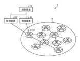
図2は、第1の実施形態に係る通信システムの構成例を示す図である。図1に示すように、通信システム1は、通信ネットワークN、設計装置10、監視装置20及び制御装置30を有する。[First embodiment]
2 is a diagram showing an example of the configuration of a communication system according to the first embodiment. As shown in FIG 1, the
通信ネットワークNは、複数のノードを含むパケット網である。例えば、ノードは、IPルータ及びL2スイッチ等である。また、通信ネットワークNのノード間は光ファイバー等のリンクで接続される。The communication network N is a packet network including multiple nodes. For example, the nodes are IP routers and L2 switches. The nodes of the communication network N are connected by links such as optical fibers.
設計装置10は、通信ネットワークNの経路設計を行う。例えば、設計装置10は、監視装置20及び制御装置30からの情報に基づきネットワーク構成を管理し、経路の設計(計算)を行う。The
監視装置20は、通信ネットワークNを監視する。例えば、監視装置20は、各リンクに流れるトラヒック量、始点ノード及び終点ノードで設定される論理パス(例えばVPN等)ごとの交流トラヒック情報を観測する。また、監視装置20は、得られたトラヒック情報を設計装置10及び制御装置30に提供する。The
制御装置30は、通信ネットワークNを制御する。例えば、制御装置30は、設計装置10によって設計された経路情報を各ノードに設定する。The
図3は、第1の実施形態に係る設計装置の構成例を示す図である。設計装置10は、監視装置20によって観測された情報の入力を受け付ける。例えば、設計装置10は、通信ネットワークNのトポロジー及び交流トラヒックの入力を受け付ける。また、設計装置10は、経路情報を制御装置30に対して出力する。Figure 3 is a diagram showing an example of the configuration of a design device according to the first embodiment. The
図3に示すように、設計装置10は、インタフェース部11、記憶部12及び制御部13を有する。As shown in FIG. 3, the
インタフェース部11は、データの入力及び出力のためのインタフェースである。例えば、インタフェース部11はNIC(Network Interface Card)である。インタフェース部11は他の装置との間でデータの送受信を行うことができる。The interface unit 11 is an interface for inputting and outputting data. For example, the interface unit 11 is a NIC (Network Interface Card). The interface unit 11 can send and receive data between other devices.
また、インタフェース部11は、マウスやキーボード等の入力装置と接続されていてもよい。また、インタフェース部11は、ディスプレイ及びスピーカ等の出力装置と接続されていてもよい。これにより、インタフェース部11は、ネットワークオペレータとのインタフェースとして機能する。The interface unit 11 may also be connected to input devices such as a mouse and a keyboard. The interface unit 11 may also be connected to output devices such as a display and a speaker. In this way, the interface unit 11 functions as an interface with the network operator.
記憶部12は、HDD(Hard Disk Drive)、SSD(Solid State Drive)、光ディスク等の記憶装置である。なお、記憶部12は、RAM(Random Access Memory)、フラッシュメモリ、NVSRAM(Non Volatile Static Random Access Memory)等のデータを書き換え可能な半導体メモリであってもよい。記憶部12は、設計装置10で実行されるOS(Operating System)や各種プログラムを記憶する。The memory unit 12 is a storage device such as a hard disk drive (HDD), a solid state drive (SSD), or an optical disk. The memory unit 12 may be a semiconductor memory in which data can be rewritten, such as a random access memory (RAM), a flash memory, or a non-volatile static random access memory (NVSRAM). The memory unit 12 stores the operating system (OS) and various programs executed by the
記憶部12は、経路DB121、トポロジーDB122及びトラヒックDB123を記憶する。The memory unit 12 stores a route DB 121, a topology DB 122 and a traffic DB 123.
経路DB121は、始点ノードと終点ノードとの間に設定される論理パスごとの経路情報を保持する。経路情報の計算方法については後述する。The route DB 121 stores route information for each logical path set between the start node and the end node. The method of calculating the route information will be described later.
トポロジーDB122は、ノードとリンクの接続情報、及び各リンクの容量情報を保持する。また、トラヒックDB123は、リンクごとのトラヒック情報、及び論理パスごとの交流トラヒック情報を管理する。Topology DB122 stores connection information between nodes and links, and capacity information for each link. Traffic DB123 manages traffic information for each link and exchange traffic information for each logical path.
なお、設計装置10は、トポロジーDB122及びトラヒックDB123から経路情報を計算し、計算した経路情報を経路DB121に格納する。また、設計装置10は、計算した経路情報を出力してもよい。The
制御部13は、設計装置10全体を制御する。制御部13は、例えば、CPU(Central Processing Unit)、MPU(Micro Processing Unit)、GPU(Graphics Processing Unit)等の電子回路や、ASIC(Application Specific Integrated Circuit)、FPGA(Field Programmable Gate Array)等の集積回路である。また、制御部13は、各種の処理手順を規定したプログラムや制御データを格納するための内部メモリを有し、内部メモリを用いて各処理を実行する。The control unit 13 controls the
制御部13は、各種のプログラムが動作することにより各種の処理部として機能する。例えば制御部13は、最短経路計算部131、最適化部132、近似計算部133及びマッピング部134を有する。The control unit 13 functions as various processing units by running various programs. For example, the control unit 13 has a shortest path calculation unit 131, an
最短経路計算部131は、指定された始点ノードと終点ノードとの間の最短経路を計算する。The shortest path calculation unit 131 calculates the shortest path between the specified start node and end node.
最適化部132は、ネットワークに含まれる隣接するノード間のリンクのそれぞれに割り当てられたトラヒック量を第1の粒度で最適化する。例えば、最適化部132は、交流トラヒック量を実数解で最適化する。例えば、第1の粒度は実数である。The
近似計算部133は、第1の粒度で最適化されたトラヒック量を第2の粒度で近似した近似解を計算する。例えば、近似計算部133は、実数解を整数解で近似する。例えば、第2の粒度は整数である。The
マッピング部134は、近似計算部133によって近似されたトラヒック量に従って、リンクによって構成される経路のそれぞれに論理パスをマッピングする。The mapping unit 134 maps logical paths to each of the routes formed by the links according to the traffic volume approximated by the
ここで、図5を用いて、交流トラヒックについて説明する。図5は、交流トラヒックを説明する図である。Here, we will explain exchange traffic using Figure 5. Figure 5 is a diagram that explains exchange traffic.
交流トラヒックは、隣接ノード間のリンクに流れる合算されたトラヒック量ではなく、始点ノードと終点ノード間の経路(リンクの集合)のトラヒック量を表す。AC traffic does not represent the combined traffic volume flowing on the links between adjacent nodes, but rather the traffic volume on the path (set of links) between the start node and the end node.
図5の例では、ノード51とノード54との間の交流トラヒックは40Gbpsである。また、ノード51とノード52との間の交流トラヒックは20Gbpsである。In the example of Figure 5, the exchange traffic between
図6は、交流トラヒックの一例を示す図である。図5のような2つの交流トラヒックが発生している場合は、図6の表に示すようなマトリクス表記がされる。Figure 6 shows an example of exchange traffic. When two exchange traffic flows occur as in Figure 5, they are expressed in a matrix as shown in the table in Figure 6.
図4を用いて、設計装置10による経路計算を詳細に説明する。図4は、経路計算の流れを説明する図である。The route calculation by the
図4に示すように、設計装置10には、パスの分解能、交流トラヒック及びトポロジーが与えられる。パスの分解能とは、経路に設定可能なトラヒック量の最小粒度(例えば、整数)である。As shown in Figure 4, the
例えば、経路に設定可能なトラヒック量の単位が決められている場合がある。この単位が最小粒度に相当する。例えば、図4のように、割り当て可能な単位が1G(bps)であれば、最小粒度は整数ということになる。For example, there may be a set unit of traffic volume that can be set for a route. This unit corresponds to the minimum granularity. For example, as in Figure 4, if the allocatable unit is 1G (bps), the minimum granularity is an integer.
図4のステップS1において、最適化部132は、交流トラヒックとトポロジーから実数解となる最適経路を計算する。例えば、最適化部132は、非特許文献2に記載されて方法で実数解を計算する。In step S1 of FIG. 4, the
図4の例では、最適化部132は、ノード51とノード53との間のリンクのトラヒック量を34.77Gのように実数で計算する。また、最適化部132は、ノード53とノード54との間のリンクのトラヒック量を29.84Gと計算する。In the example of FIG. 4, the
ここで、非特許文献2に記載の線形計画法で算出される解は実数解であるため、与えられたパスの分解能では設定できない粒度の解ということになる。Here, the solution calculated by the linear programming method described in non-patent document 2 is a real solution, and therefore the solution has a granularity that cannot be set with the resolution of a given path.
そこで、ステップS2において、近似計算部133は、最適化部132によって計算された解を、パスの分解能の倍数となる値、すなわち最小粒度で近似する。例えば、近似計算部133は、パスの分解能より低い桁(ここでは小数点第1位以下)に対して四捨五入もしくは切り捨てを行う。Therefore, in step S2, the
図4の例では、近似計算部133は、ノード51とノード53との間のリンクのトラヒック量を34.77Gから35Gに近似する。また、近似計算部133は、ノード53とノード54との間のリンクのトラヒック量を29.84Gから30Gに近似する。In the example of Figure 4, the
さらに、ステップS3において、マッピング部134は、各経路にトラヒックをマッピングする。このとき、マッピング部134は、各リンクに割り当てられるトラヒック量が、近似計算部133の計算結果になるべく近くなるようにマッピングを行う。Furthermore, in step S3, the mapping unit 134 maps the traffic to each route. At this time, the mapping unit 134 performs mapping so that the traffic volume assigned to each link is as close as possible to the calculation result of the
図4の例では、マッピング部134は、ノード51とノード54との間の経路であって、ノード53を経由する経路に、1Gの論理パスを30本マッピングする。In the example of Figure 4, the mapping unit 134 maps 30 1G logical paths onto the route between
なお、本実施形態の設計装置10による設計処理(各種計算及びマッピング)は、通信ネットワークNの経路を初期設計する時だけでなく、交流トラヒックが変動した時に行われてもよい。In addition, the design processing (various calculations and mapping) by the
交流トラヒックが変動した場合、設計装置10は、トラヒック量の計算を再度行い、交流トラヒックの変動が起こる前の状態との全体差分をとることができる。また、設計装置10は、指定した対地間の経路計算を行い、当該指定した対地間のみの差分をとることで、網運用時のトラヒック変動に対する解を得るようにしてもよい。When the AC traffic fluctuates, the
[第1の実施形態の処理]
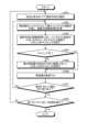
図7は、第1の実施形態に係る設計装置の処理の流れを示すフローチャートである。図7に示すように、設計装置10は各リンクのトラヒック量の実数解を計算する(ステップS10)。[Processing of the First Embodiment]
Fig. 7 is a flowchart showing the flow of processing in the design device according to the first embodiment. As shown in Fig. 7, the
次に、設計装置10は、実数解を最小粒度(例えば整数)で近似する(ステップS20)。そして、設計装置10は、近似した整数解を基に各経路への論理パスのマッピングを行う(ステップS30)。Next, the
図8は、マッピング処理の流れを示すフローチャートである。図8に示す処理は、図7のステップS30の処理に相当する。また、図7の各ステップと図9の例とを適宜対応付けて説明を行う。図9は、マッピング処理の一例を示す図である。Figure 8 is a flowchart showing the flow of the mapping process. The process shown in Figure 8 corresponds to the process of step S30 in Figure 7. In addition, the steps in Figure 7 will be explained in association with the example in Figure 9 as appropriate. Figure 9 is a diagram showing an example of the mapping process.
まず、マッピング部134は、始点ノードと終点ノードのペア(選択対地)を選択する(ステップS301)。図9の例では、マッピング部134は、近似された経路情報におけるノード51を始点ノードに選択し、ノード54を終点ノードに選択する。このとき、選択対地はノード51とノード54である。First, the mapping unit 134 selects a pair of a start node and an end node (selected pair) (step S301). In the example of FIG. 9, the mapping unit 134 selects
ここで、実数解は全ての始点ノード及び終点ノードのペアに対して計算されるが、その実数解はペアごとに計算されるものであるため、マッピング部134はどのような順番でペアを選択していってもよい。Here, the real solution is calculated for all pairs of start and end nodes, but since the real solution is calculated for each pair, the mapping unit 134 may select the pairs in any order.
次に、最短経路計算部131は、残容量(近似されたトラヒック量)をリンクコストとして最小リンクコスト経路を計算し、複数の経路候補を計算する(ステップS302)。図9の例では、最短経路計算部131は、下記の経路候補を計算する。
第1の経路候補:ノード51→ノード52→ノード54(リンクコスト総和:5+10=15)
第2の経路候補:ノード51→ノード53→ノード52→ノード54(リンクコスト総和:35+5+10=50)
第3の経路候補:ノード51→ノード52→ノード53→ノード54(リンクコスト総和:5+5+30=40)
第4の経路候補:ノード51→ノード53→ノード54(リンクコスト総和:35+30=65) Next, the shortest route calculation unit 131 calculates a minimum link cost route by taking the remaining capacity (approximated traffic volume) as the link cost, and calculates multiple route candidates (step S302). In the example of FIG. 9, the shortest route calculation unit 131 calculates the following route candidates:
First route candidate:
Second route candidate:
Third route candidate:
Fourth route candidate:
最短経路計算部131は、Dijkstra法を実行し一度利用したリンクを削除してk個の経路を計算する方法、K-shortest pathアルゴリズムを用いてリンク利用の重複があるk個の経路を計算する方法、スーバル法を用いてDisjointなK個の経路を計算する方法等により複数経路候補を計算することができる。The shortest path calculation unit 131 can calculate multiple candidate paths by, for example, performing the Dijkstra algorithm to calculate k paths by deleting links that have been used once, using the K-shortest path algorithm to calculate k paths with overlapping link usage, or using the Subal method to calculate K disjoint paths.
図10はスーバル法を説明する図である。図10に示すように、スーバル法は以下の手順で行われる。
(1)Dijkstra法等により、最短コスト経路を計算する。
(2)最短コスト経路上のリンクを逆向きにするとともに、リンクコストをマイナスにする。
(3)Bellman-Ford法等により、最短コスト経路を計算する。
(4)2つの経路計算結果をあわせ、共通部分を除去し、冗長パスを得る。 10 is a diagram for explaining the Subal method. As shown in FIG. 10, the Subal method is performed in the following procedure.
(1) Calculate the shortest cost route using the Dijkstra algorithm or similar.
(2) Reverse the links on the shortest cost route and make the link costs negative.
(3) Calculate the shortest cost route using the Bellman-Ford method or similar.
(4) The two route calculation results are combined, and the common parts are removed to obtain redundant paths.
スーバル法は、ノード/リンク冗長パス計算アルゴリズムである。スーバル法によれば、ノード/リンク冗長パスが存在する場合、必ず発見することが可能である。スーバル法では、現用パス、予備パスのコストの和が最小となるような組が発見される。一方、Dijkstra法(最短経路探索アルゴリズム)を2回適用する方法では、ノード/リンク冗長パスが存在しても発見できないことがある。The Subal method is an algorithm for calculating node/link redundant paths. With the Subal method, it is always possible to discover node/link redundant paths if they exist. The Subal method finds a pair that minimizes the sum of the costs of the active path and the backup path. On the other hand, the method of applying the Dijkstra method (shortest route search algorithm) twice may not be able to discover node/link redundant paths even if they exist.
マッピング部134は、選択対地の経路候補に対し、リンクコスト総和の小さいものから、与えられた分解能でトラヒックのマッピングを試す(ステップS303)。図9の例では、マッピング部134は、1周目においてはリンクコスト総和が最小の第1の経路候補へのマッピングを試す。The mapping unit 134 attempts to map traffic to the selected destination route candidates with the given resolution, starting from the route candidate with the smallest total link cost (step S303). In the example of FIG. 9, the mapping unit 134 attempts to map traffic to the first route candidate with the smallest total link cost in the first round.
マッピングができた場合(ステップS304、Yes)、マッピング部134はステップS306へ進む。そして、マッピング部134は、残容量を更新する(ステップS306)。図9の例では、マッピング部134は、1周目においては第1の経路候補の各リンクの残容量を更新する。If mapping is possible (step S304, Yes), the mapping unit 134 proceeds to step S306. Then, the mapping unit 134 updates the remaining capacity (step S306). In the example of FIG. 9, the mapping unit 134 updates the remaining capacity of each link of the first route candidate in the first round.
なお、残容量が0に更新されたリンクのリンクコストは、次周以降十分大きな値(例えば無限大)とみなされる。In addition, the link cost of a link whose remaining capacity has been updated to 0 will be considered to be a sufficiently large value (e.g., infinity) from the next round onwards.
いずれの経路候補についてもマッピングができなかった場合(ステップS304、No)、マッピング部134はステップS305へ進む。そして、マッピング部134は、最も残容量の総和が大きい経路に対してトラヒックのマッピングを試す(ステップS305)。If mapping cannot be performed for any of the route candidates (step S304, No), the mapping unit 134 proceeds to step S305. Then, the mapping unit 134 attempts to map the traffic to the route with the largest total remaining capacity (step S305).
ここで、マッピング部134は、要求トラヒック量(選択対地で発生している交流トラヒックの量)を全て割り当てた場合(ステップS307、Yes)、ステップS308へ進む。一方、マッピング部134は、要求トラヒック量を全て割り当てていない場合(ステップS307、No)、ステップS302へ戻り処理を繰り返す。Here, if the mapping unit 134 has allocated all of the requested traffic volume (the volume of the exchange traffic occurring at the selected destination) (step S307, Yes), the mapping unit 134 proceeds to step S308. On the other hand, if the mapping unit 134 has not allocated all of the requested traffic volume (step S307, No), the mapping unit 134 returns to step S302 and repeats the process.
また、マッピング部134は、全てのペアに対して処理を実行した場合(ステップS308、Yes)、処理を終了する。一方、マッピング部134は、全てのペアに対して処理を実行していない場合(ステップS308、No)、ステップS301へ戻り処理を繰り返す。Furthermore, if the mapping unit 134 has performed the process for all pairs (step S308, Yes), the mapping unit 134 ends the process. On the other hand, if the mapping unit 134 has not performed the process for all pairs (step S308, No), the mapping unit 134 returns to step S301 and repeats the process.
このように、マッピング部134は、近似されたトラヒック量が少ない経路へのマッピングを優先し、近似されたトラヒック量が足りない場合は、近似されたトラヒック量が最も多い経路に優先してマッピングを行う。In this way, the mapping unit 134 prioritizes mapping to a route with a small amount of approximated traffic volume, and if the amount of approximated traffic volume is insufficient, it prioritizes mapping to a route with the largest amount of approximated traffic volume.
図9の例では、残容量が少ない経路から順にトラヒックがマッピングされていき、残容量が0以下となるとリンクコストとしては大きい値として扱われるため、残容量がある経路へとトラヒックのマッピングが行われていく。In the example shown in Figure 9, traffic is mapped to routes starting with those with the least remaining capacity, and when the remaining capacity falls below 0, the link cost is treated as a large value, so traffic is mapped to routes with remaining capacity.
なお、マッピングされるトラヒック量は分解能に応じて一律であるため、残容量が少ない経路から割り当てる方法と、逆に残容量が多いトラヒック量から割り当てる方法とでは、マッピング先の容量が変化するだけであるため、性能差は無いものと考えられる。In addition, since the traffic volume to be mapped is uniform depending on the resolution, there is no performance difference between the method of allocating from routes with little remaining capacity and the method of allocating from traffic volumes with a lot of remaining capacity, since the only difference is the capacity of the mapping destination.
[第1の実施形態の効果]
これまで説明してきたように、最適化部132は、ネットワークに含まれる隣接するノード間のリンクのそれぞれに割り当てられたトラヒック量を第1の粒度で最適化する。近似計算部133は、第1の粒度で最適化されたトラヒック量を第2の粒度で近似した近似解を計算する。[Effects of the First Embodiment]
As described above, the
前述の通り、従来の技術には、実数解のため実際に網に設定できない、もしくはキャリア網規模で演算ができないといったことから実用的ではないという問題があった。本実施形態では、最適解を近似しつつ実際に設定可能な解が算出される。その結果、本実施形態によれば、通信ネットワークにおけるトラヒック収容効率の高い経路設計を、現実的な方法により行うことが可能になる。さらに、トラヒック収容効率の高い経路設計により、設備コスト削減という効果が生じる。As mentioned above, conventional technologies have problems in that they are not practical because they are real number solutions and therefore cannot be actually set in the network, or calculations cannot be performed on a carrier network scale. In this embodiment, a solution that can actually be set is calculated while approximating the optimal solution. As a result, this embodiment makes it possible to design routes with high traffic accommodation efficiency in a communication network using a realistic method. Furthermore, route design with high traffic accommodation efficiency has the effect of reducing equipment costs.
また、最適化部132は、交流トラヒック量を実数解で最適化する。近似計算部133は、実数解を整数解で近似する。これにより、1Gbps単位の論理パスがマッピング可能になる。In addition, the
また、マッピング部134は、近似計算部133によって近似されたトラヒック量に従って、リンクによって構成される経路のそれぞれに論理パスをマッピングする。これにより、設計装置10は、近似計算の結果を実際の通信ネットワークに反映させることができる。In addition, the mapping unit 134 maps logical paths to each of the routes formed by the links according to the traffic volume approximated by the
また、マッピング部134は、近似されたトラヒック量が少ない経路へのマッピングを優先し、近似されたトラヒック量が足りない場合は、近似されたトラヒック量が最も多い経路に優先してマッピングを行う。これにより、設計装置10は、効率の良いマッピングを実現することができる。In addition, the mapping unit 134 prioritizes mapping to a route with a small amount of approximated traffic, and if the amount of approximated traffic is insufficient, prioritizes mapping to a route with the largest amount of approximated traffic. This allows the
[システム構成等]
また、図示した各装置の各構成要素は機能概念的なものであり、必ずしも物理的に図示のように構成されていることを要しない。すなわち、各装置の分散及び統合の具体的形態は図示のものに限られず、その全部又は一部を、各種の負荷や使用状況等に応じて、任意の単位で機能的又は物理的に分散又は統合して構成することができる。さらに、各装置にて行われる各処理機能は、その全部又は任意の一部が、CPU及び当該CPUにて解析実行されるプログラムにて実現され、あるいは、ワイヤードロジックによるハードウェアとして実現され得る。なお、プログラムは、CPUだけでなく、GPU等の他のプロセッサによって実行されてもよい。[System configuration, etc.]
In addition, each component of each device shown in the figure is functionally conceptual, and does not necessarily have to be physically configured as shown in the figure. In other words, the specific form of distribution and integration of each device is not limited to that shown in the figure, and all or a part of it can be functionally or physically distributed or integrated in any unit depending on various loads, usage conditions, etc. Furthermore, each processing function performed by each device can be realized in whole or in any part by a CPU and a program analyzed and executed by the CPU, or can be realized as hardware by wired logic. Note that the program may be executed not only by the CPU but also by other processors such as a GPU.
また、本実施形態において説明した各処理のうち、自動的に行われるものとして説明した処理の全部又は一部を手動的に行うこともでき、あるいは、手動的に行われるものとして説明した処理の全部又は一部を公知の方法で自動的に行うこともできる。この他、上記文書中や図面中で示した処理手順、制御手順、具体的名称、各種のデータやパラメータを含む情報については、特記する場合を除いて任意に変更することができる。Furthermore, among the processes described in this embodiment, all or part of the processes described as being performed automatically can be performed manually, or all or part of the processes described as being performed manually can be performed automatically by a known method. In addition, the information including the processing procedures, control procedures, specific names, various data and parameters shown in the above documents and drawings can be changed as desired unless otherwise specified.
[プログラム]
一実施形態として、設計装置10は、パッケージソフトウェアやオンラインソフトウェアとして上記の設計処理を実行する設計プログラムを所望のコンピュータにインストールさせることによって実装できる。例えば、上記の設計プログラムを情報処理装置に実行させることにより、情報処理装置を設計装置10として機能させることができる。ここで言う情報処理装置には、デスクトップ型又はノート型のパーソナルコンピュータが含まれる。また、その他にも、情報処理装置にはスマートフォン、携帯電話機やPHS(Personal Handyphone System)等の移動体通信端末、さらには、PDA(Personal Digital Assistant)等のスレート端末等がその範疇に含まれる。[program]
In one embodiment, the
また、設計装置10は、ユーザが使用する端末装置をクライアントとし、当該クライアントに上記の設計処理に関するサービスを提供する設計サーバ装置として実装することもできる。例えば、設計サーバ装置は、通信ネットワークの交流トラヒック及びトポロジーを入力とし、論理パスのマッピング結果を出力とする設計サービスを提供するサーバ装置として実装される。この場合、設計サーバ装置は、Webサーバとして実装することとしてもよいし、アウトソーシングによって上記の設計処理に関するサービスを提供するクラウドとして実装することとしてもかまわない。The
図11は、設計プログラムを実行するコンピュータの一例を示す図である。コンピュータ1000は、例えば、メモリ1010、CPU1020を有する。また、コンピュータ1000は、ハードディスクドライブインタフェース1030、ディスクドライブインタフェース1040、シリアルポートインタフェース1050、ビデオアダプタ1060、ネットワークインタフェース1070を有する。これらの各部は、バス1080によって接続される。Figure 11 is a diagram showing an example of a computer that executes a design program. The
メモリ1010は、ROM(Read Only Memory)1011及びRAM(Random Access Memory)1012を含む。ROM1011は、例えば、BIOS(Basic Input Output System)等のブートプログラムを記憶する。ハードディスクドライブインタフェース1030は、ハードディスクドライブ1090に接続される。ディスクドライブインタフェース1040は、ディスクドライブ1100に接続される。例えば磁気ディスクや光ディスク等の着脱可能な記憶媒体が、ディスクドライブ1100に挿入される。シリアルポートインタフェース1050は、例えばマウス1110、キーボード1120に接続される。ビデオアダプタ1060は、例えばディスプレイ1130に接続される。The
ハードディスクドライブ1090は、例えば、OS1091、アプリケーションプログラム1092、プログラムモジュール1093、プログラムデータ1094を記憶する。すなわち、設計装置10の各処理を規定するプログラムは、コンピュータにより実行可能なコードが記述されたプログラムモジュール1093として実装される。プログラムモジュール1093は、例えばハードディスクドライブ1090に記憶される。例えば、設計装置10における機能構成と同様の処理を実行するためのプログラムモジュール1093が、ハードディスクドライブ1090に記憶される。なお、ハードディスクドライブ1090は、SSD(Solid State Drive)により代替されてもよい。The hard disk drive 1090 stores, for example, an
また、上述した実施形態の処理で用いられる設定データは、プログラムデータ1094として、例えばメモリ1010やハードディスクドライブ1090に記憶される。そして、CPU1020は、メモリ1010やハードディスクドライブ1090に記憶されたプログラムモジュール1093やプログラムデータ1094を必要に応じてRAM1012に読み出して、上述した実施形態の処理を実行する。In addition, the setting data used in the processing of the above-described embodiment is stored as
なお、プログラムモジュール1093やプログラムデータ1094は、ハードディスクドライブ1090に記憶される場合に限らず、例えば着脱可能な記憶媒体に記憶され、ディスクドライブ1100等を介してCPU1020によって読み出されてもよい。あるいは、プログラムモジュール1093及びプログラムデータ1094は、ネットワーク(LAN(Local Area Network)、WAN(Wide Area Network)等)を介して接続された他のコンピュータに記憶されてもよい。そして、プログラムモジュール1093及びプログラムデータ1094は、他のコンピュータから、ネットワークインタフェース1070を介してCPU1020によって読み出されてもよい。Note that the
N 通信ネットワーク
1 通信システム
10 設計装置
11 インタフェース部
12 記憶部
13 制御部
20 監視装置
30 制御装置
121 経路DB
122 トポロジーDB
123 トラヒックDB
131 最短経路計算部
132 最適化部
133 近似計算部
134 マッピング部
122 Topology DB
123 Traffic DB
131 Shortest
Claims (4)
Translated fromJapanese前記第1の粒度で最適化されたトラヒック量を第2の粒度で近似した近似解を残容量として計算する近似計算部と、
前記残容量の総和が最も少ない経路へ優先して論路パスをマッピングし、前記経路の前記残容量の総和が足りない場合は、前記残容量の総和が最も多い経路に優先してマッピングを行うマッピング部と、
を有することを特徴とする設計装置。 an optimization unit that optimizes, with a first granularity, a traffic volume allocated to each of links between adjacent nodes included in the network;
an approximation calculation unit that calculates an approximation solution obtained by approximating the traffic volume optimized at the first granularity at a second granularityas a remaining capacity ;
a mapping unit that maps logical paths with priority to a path having the smallest total remaining capacity, and when the total remaining capacity of the path is insufficient, maps logical paths with priority to a path having the largest total remaining capacity;
A design device comprising:
前記近似計算部は、前記実数解を整数解で近似することを特徴とする請求項1に記載の設計装置。 The optimization unit optimizes the exchange traffic with a real solution,
2. The design apparatus according to claim 1, wherein the approximation calculation unit approximates the real solution with an integer solution.
ネットワークに含まれる隣接するノード間のリンクのそれぞれに割り当てられたトラヒック量を第1の粒度で最適化する最適化工程と、
前記第1の粒度で最適化されたトラヒック量を第2の粒度で近似した近似解を残容量として計算する近似計算工程と、
前記残容量の総和が最も少ない経路へ優先して論路パスをマッピングし、前記経路の前記残容量の総和が足りない場合は、前記残容量の総和が最も多い経路に優先してマッピングを行うマッピング工程と、
を含むことを特徴とする設計方法。 A design method executed by a design device, comprising:
an optimization step of optimizing, with a first granularity, a traffic volume allocated to each of links between adjacent nodes included in the network;
an approximation calculation step of approximating the traffic volume optimized at the first granularity at a second granularity to calculate an approximation solutionas a remaining capacity ;
a mapping step of mapping the logical path with priority to the path having the smallest total remaining capacity, and, when the total remaining capacity of the path is insufficient, mapping with priority to the path having the largest total remaining capacity;
A design method comprising:
Applications Claiming Priority (1)
| Application Number | Priority Date | Filing Date | Title |
|---|---|---|---|
| PCT/JP2021/005371WO2022172423A1 (en) | 2021-02-12 | 2021-02-12 | Designing device, designing method and designing program |
Publications (2)
| Publication Number | Publication Date |
|---|---|
| JPWO2022172423A1 JPWO2022172423A1 (en) | 2022-08-18 |
| JP7605231B2true JP7605231B2 (en) | 2024-12-24 |
Family
ID=82838551
Family Applications (1)
| Application Number | Title | Priority Date | Filing Date |
|---|---|---|---|
| JP2022581134AActiveJP7605231B2 (en) | 2021-02-12 | 2021-02-12 | DESIGN APPARATUS, DESIGN METHOD, AND DESIGN PROGRAM |
Country Status (3)
| Country | Link |
|---|---|
| US (1) | US20240121190A1 (en) |
| JP (1) | JP7605231B2 (en) |
| WO (1) | WO2022172423A1 (en) |
Citations (1)
| Publication number | Priority date | Publication date | Assignee | Title |
|---|---|---|---|---|
| JP2000232395A (en) | 1998-11-05 | 2000-08-22 | Lucent Technol Inc | Linear programming method of network design for transferring traffic from end node to core network at smallest cost |
Family Cites Families (9)
| Publication number | Priority date | Publication date | Assignee | Title |
|---|---|---|---|---|
| US6069894A (en)* | 1995-06-12 | 2000-05-30 | Telefonaktiebolaget Lm Ericsson | Enhancement of network operation and performance |
| US5854903A (en)* | 1995-11-07 | 1998-12-29 | Lucent Technologies Inc. | Optimization method for routing and logical network design in multi-service networks |
| US6331986B1 (en)* | 1998-04-24 | 2001-12-18 | Lucent Technologies Inc. | Method for resource allocation and routing in multi-service virtual private networks |
| AU2001281240A1 (en)* | 2000-08-10 | 2002-02-25 | University Of Pittsburgh | Apparatus and method for spare capacity allocation |
| GB0026703D0 (en)* | 2000-11-01 | 2000-12-20 | Parc Technologies Ltd | Traffic flow optimisation system |
| GB2386033B (en)* | 2002-03-01 | 2005-08-24 | Parc Technologies Ltd | Traffic flow optimisation system |
| US7593348B2 (en)* | 2004-02-11 | 2009-09-22 | Alcatel-Lucent Usa Inc. | Traffic-independent allocation of working and restoration capacity in networks |
| JP5655619B2 (en)* | 2011-02-21 | 2015-01-21 | 富士通株式会社 | Network design system |
| WO2022168155A1 (en)* | 2021-02-02 | 2022-08-11 | 日本電信電話株式会社 | Traffic engineering device, traffic engineering method, and traffic engineering program |
- 2021
- 2021-02-12JPJP2022581134Apatent/JP7605231B2/enactiveActive
- 2021-02-12USUS18/276,953patent/US20240121190A1/ennot_activeAbandoned
- 2021-02-12WOPCT/JP2021/005371patent/WO2022172423A1/ennot_activeCeased
Patent Citations (1)
| Publication number | Priority date | Publication date | Assignee | Title |
|---|---|---|---|---|
| JP2000232395A (en) | 1998-11-05 | 2000-08-22 | Lucent Technol Inc | Linear programming method of network design for transferring traffic from end node to core network at smallest cost |
Non-Patent Citations (2)
| Title |
|---|
| Yufei Wang, et al.,Explicit routing algorithms for Internet traffic engineering,Proceedings Eight International Conference on Computer Communications and Networks,1999年10月11日,pp.582-588 |
| 蔡 東風, 石塚 満,線形計画法を利用した離散制約最適化問題の効率的近似解法,人工知能学会誌,1999 年 14 巻 2 号,1999年03月01日,pp. 334-341 |
Also Published As
| Publication number | Publication date |
|---|---|
| WO2022172423A1 (en) | 2022-08-18 |
| US20240121190A1 (en) | 2024-04-11 |
| JPWO2022172423A1 (en) | 2022-08-18 |
Similar Documents
| Publication | Publication Date | Title |
|---|---|---|
| CN112585585B (en) | Joint placement and linking of virtual network functions for extensible genetic algorithm-based virtualized systems | |
| Abuzaid et al. | Contracting wide-area network topologies to solve flow problems quickly | |
| Kuo et al. | Deploying chains of virtual network functions: On the relation between link and server usage | |
| Farooq Butt et al. | Topology-awareness and reoptimization mechanism for virtual network embedding | |
| Avin et al. | Demand-aware network design with minimal congestion and route lengths | |
| US11855893B2 (en) | Tag-based cross-region segment management | |
| CN110247713B (en) | A method and device for virtual service mapping based on quantum key distribution light network | |
| EP2979409A1 (en) | A method and system to allocate bandwidth for heterogeneous bandwidth request in cloud computing networks | |
| US20160226789A1 (en) | Method and system to rebalance constrained services in a cloud using a genetic algorithm | |
| US11799755B2 (en) | Metadata-based cross-region segment routing | |
| US11706146B1 (en) | Directing network traffic using local routing decisions with a global overview | |
| CN104917659B (en) | A kind of mapping method of virtual network based on virtual network connection performance | |
| US10673764B2 (en) | Distributed affinity tracking for network connections | |
| JP2017500816A (en) | Traffic engineering for large data center networks | |
| US11991211B1 (en) | Symmetric cross-region network data flow management | |
| Paschos et al. | Network slicing with splittable flows is hard | |
| Shanbhag et al. | VHub: Single-stage virtual network mapping through hub location | |
| CN113535381B (en) | Service function chain mapping method, device and equipment based on improved genetic algorithm | |
| Madani et al. | Deploying disaster-resilient service function chains using adaptive multi-path routing | |
| US11936558B1 (en) | Dynamic evaluation and implementation of network mutations | |
| US10841225B2 (en) | Load balancing using dynamically resizable consistent hashing | |
| US12348571B2 (en) | Network configuration analysis and management | |
| JP7605231B2 (en) | DESIGN APPARATUS, DESIGN METHOD, AND DESIGN PROGRAM | |
| Lu et al. | Cost-efficient resource provisioning in delay-sensitive cooperative fog computing | |
| US20180034696A1 (en) | System and method for joint embedding and backup provisioning in virtual networks |
Legal Events
| Date | Code | Title | Description |
|---|---|---|---|
| A621 | Written request for application examination | Free format text:JAPANESE INTERMEDIATE CODE: A621 Effective date:20230628 | |
| A131 | Notification of reasons for refusal | Free format text:JAPANESE INTERMEDIATE CODE: A131 Effective date:20240611 | |
| A521 | Request for written amendment filed | Free format text:JAPANESE INTERMEDIATE CODE: A523 Effective date:20240813 | |
| TRDD | Decision of grant or rejection written | ||
| A01 | Written decision to grant a patent or to grant a registration (utility model) | Free format text:JAPANESE INTERMEDIATE CODE: A01 Effective date:20241112 | |
| A61 | First payment of annual fees (during grant procedure) | Free format text:JAPANESE INTERMEDIATE CODE: A61 Effective date:20241125 | |
| R150 | Certificate of patent or registration of utility model | Ref document number:7605231 Country of ref document:JP Free format text:JAPANESE INTERMEDIATE CODE: R150 | |
| S533 | Written request for registration of change of name | Free format text:JAPANESE INTERMEDIATE CODE: R313533 |