JP7600947B2 - Vehicle suspension control device and vehicle suspension control method - Google Patents
Vehicle suspension control device and vehicle suspension control methodDownload PDFInfo
- Publication number
- JP7600947B2 JP7600947B2JP2021160007AJP2021160007AJP7600947B2JP 7600947 B2JP7600947 B2JP 7600947B2JP 2021160007 AJP2021160007 AJP 2021160007AJP 2021160007 AJP2021160007 AJP 2021160007AJP 7600947 B2JP7600947 B2JP 7600947B2
- Authority
- JP
- Japan
- Prior art keywords
- control
- control amount
- road surface
- amount
- vehicle
- Prior art date
- Legal status (The legal status is an assumption and is not a legal conclusion. Google has not performed a legal analysis and makes no representation as to the accuracy of the status listed.)
- Active
Links
Images


Landscapes
- Vehicle Body Suspensions (AREA)
Description
Translated fromJapanese本開示は、サスペンションストロークを制御するアクチュエータを備える車両用サスペンション制御装置及び車両用サスペンション制御方法に関する。This disclosure relates to a vehicle suspension control device that includes an actuator that controls the suspension stroke, and a vehicle suspension control method.
特許文献1は、車両用アクティブサスペンションを開示している。このアクティブサスペンションは、サスペンションストロークを制御する油圧式のアクチュエータと、コントローラとを備えている。アクチュエータは、車輪毎に配置されている。コントローラは、ロール制御出力と乗心地制御出力とを車輪毎に加算して得られる駆動制御出力に応じて制御弁を独立に作動させることにより、各アクチュエータへの流体圧の給排を制御する。
特許文献1に記載の技術によれば、乗心地制御とロール制御(姿勢制御)の両立を図るために、上述のようにロール制御出力と乗心地制御出力とを車輪毎に加算して得られる駆動制御出力に応じて各アクチュエータの制御弁が独立に制御される。しかしながら、サスペンションストロークを制御するアクチュエータの出力には限りがある。このため、ロール制御出力及び乗心地制御出力の双方を常に満足できる出力をアクチュエータが発生させられるとは限らない。そして、特許文献1に記載のようにロール制御出力と乗心地制御出力とを単に加算したとしても、路面状態、又は、車両操作状態及び車両運動状態の少なくとも一方によっては、適切なサスペンション制御とならない可能性がある。According to the technology described in
本開示は、上述のような課題に鑑みてなされたものであり、路面状態を考慮しつつ、又は、車両操作状態及び車両運動状態の少なくとも一方を考慮しつつ、乗心地制御と姿勢制御とを両立できるようにした車両用サスペンション制御装置及び車両用サスペンション制御方法を提供することを目的とする。The present disclosure has been made in consideration of the above-mentioned problems, and aims to provide a vehicle suspension control device and vehicle suspension control method that can achieve both ride comfort control and attitude control while taking into account road surface conditions or at least one of the vehicle operation state and the vehicle motion state.
本開示の一態様に係る車両用サスペンション制御装置は、アクチュエータと、電子制御ユニットと、を備える。アクチュエータは、制御対象輪のサスペンションストロークを制御する。電子制御ユニットは、路面入力に対する乗心地制御のための第1要求制御量を算出する第1算出処理と、車両操作入力に対する姿勢制御のための第2要求制御量を算出する第2算出処理と、を実行する。また、電子制御ユニットは、第1要求制御量と第2要求制御量との和がアクチュエータによって出力可能な制御量範囲を超える場合、路面入力情報に基づいて第2要求制御量を小さく制限する調停処理を実行する。A vehicle suspension control device according to one aspect of the present disclosure includes an actuator and an electronic control unit. The actuator controls the suspension stroke of a controlled wheel. The electronic control unit executes a first calculation process to calculate a first required control amount for ride comfort control in response to a road surface input, and a second calculation process to calculate a second required control amount for attitude control in response to a vehicle operation input. In addition, when the sum of the first required control amount and the second required control amount exceeds the range of control amounts that can be output by the actuator, the electronic control unit executes an arbitration process to limit the second required control amount to a small amount based on the road surface input information.
調停処理において、電子制御ユニットは、路面入力情報に含まれる路面入力が大きいほど、第2要求制御量に含まれる制御ゲインを小さくしてもよい。In the arbitration process, the electronic control unit may reduce the control gain included in the second required control amount as the road surface input included in the road surface input information increases.
調停処理において、電子制御ユニットは、路面入力情報に含まれる路面入力速度が高いほど、第2要求制御量に含まれる制御ゲインを小さくしてもよい。In the arbitration process, the electronic control unit may reduce the control gain included in the second required control amount as the road surface input speed included in the road surface input information increases.
調停処理において、電子制御ユニットは、路面入力情報に含まれる路面入力の高周波成分が大きいほど、第2要求制御量に含まれる制御ゲインを小さくしてもよい。In the arbitration process, the electronic control unit may reduce the control gain included in the second required control amount as the high-frequency components of the road surface input included in the road surface input information become larger.
調停処理において、電子制御ユニットは、路面入力情報に含まれる路面入力が閾値以上である場合、サスペンションバネ特性に基づいて第2要求制御量を小さく制限してもよい。In the arbitration process, if the road surface input included in the road surface input information is equal to or greater than a threshold value, the electronic control unit may limit the second required control amount to a small value based on the suspension spring characteristics.
姿勢制御は、ロール制御及びピッチ制御の少なくとも一方を含んでもよい。そして、サスペンションバネ特性に基づく第2要求制御量の制限は、ロール角及びピッチ角の少なくとも一方がゼロとなるように第2要求制御量に含まれる制御ゲインを変更することを含んでもよい。The attitude control may include at least one of roll control and pitch control. Furthermore, limiting the second required control amount based on the suspension spring characteristics may include changing a control gain included in the second required control amount so that at least one of the roll angle and the pitch angle becomes zero.
本開示の他の態様に係る車両用サスペンション制御装置は、アクチュエータと、電子制御ユニットと、を備える。アクチュエータは、制御対象輪のサスペンションストロークを制御する。電子制御ユニットは、路面入力に対する乗心地制御のための第1要求制御量を算出する第1算出処理と、車両操作入力に対する姿勢制御のための第2要求制御量を算出する第2算出処理と、を実行する。また、電子制御ユニットは、第1要求制御量と第2要求制御量との和がアクチュエータによって出力可能な制御量範囲を超える場合、車両操作情報及び車両運動情報の少なくとも一方に基づいて第1要求制御量を小さく制限する調停処理を実行する。A vehicle suspension control device according to another aspect of the present disclosure includes an actuator and an electronic control unit. The actuator controls the suspension stroke of a controlled wheel. The electronic control unit executes a first calculation process to calculate a first required control amount for ride comfort control in response to a road surface input, and a second calculation process to calculate a second required control amount for attitude control in response to a vehicle operation input. In addition, when the sum of the first required control amount and the second required control amount exceeds the control amount range that can be output by the actuator, the electronic control unit executes an arbitration process to limit the first required control amount to a small amount based on at least one of vehicle operation information and vehicle motion information.
調停処理において、電子制御ユニットは、車両操作情報及び車両運動情報の少なくとも一方に基づく指標である乗心地制御に対する姿勢制御の優先度が高いほど、第1要求制御量に含まれる制御ゲインを小さくしてもよい。In the arbitration process, the electronic control unit may reduce the control gain included in the first required control amount as the priority of posture control over ride comfort control, which is an index based on at least one of vehicle operation information and vehicle motion information, increases.
本開示の一態様に係る車両用サスペンション制御方法は、制御対象輪のサスペンションストロークを制御するアクチュエータを備える車両用サスペンションを制御する。この制御方法は、路面入力に対する乗心地制御のための第1要求制御量を算出する第1算出処理と、車両操作入力に対する姿勢制御のための第2要求制御量を算出する第2算出処理と、第1要求制御量と第2要求制御量との和がアクチュエータによって出力可能な制御量範囲を超える場合、路面入力情報に基づいて第2要求制御量を小さく制限する調停処理と、を含む。A vehicle suspension control method according to one aspect of the present disclosure controls a vehicle suspension having an actuator that controls the suspension stroke of a controlled wheel. This control method includes a first calculation process that calculates a first required control amount for ride comfort control in response to a road surface input, a second calculation process that calculates a second required control amount for attitude control in response to a vehicle operation input, and an arbitration process that limits the second required control amount to a small amount based on road surface input information when the sum of the first required control amount and the second required control amount exceeds the range of control amounts that can be output by the actuator.
本開示の他の態様に係る車両用サスペンション制御方法は、制御対象輪のサスペンションストロークを制御するアクチュエータを備える車両用サスペンションを制御する。この制御方法は、路面入力に対する乗心地制御のための第1要求制御量を算出する第1算出処理と、車両操作入力に対する姿勢制御のための第2要求制御量を算出する第2算出処理と、第1要求制御量と第2要求制御量との和がアクチュエータによって出力可能な制御量範囲を超える場合、車両操作情報及び車両運動情報の少なくとも一方に基づいて第1要求制御量を小さく制限する調停処理と、を含む。A vehicle suspension control method according to another aspect of the present disclosure controls a vehicle suspension having an actuator that controls the suspension stroke of a controlled wheel. This control method includes a first calculation process that calculates a first required control amount for ride comfort control in response to a road surface input, a second calculation process that calculates a second required control amount for attitude control in response to a vehicle operation input, and an arbitration process that limits the first required control amount to a small amount based on at least one of vehicle operation information and vehicle motion information when the sum of the first required control amount and the second required control amount exceeds the range of control amounts that can be output by the actuator.
本開示の一態様に係る車両用サスペンション制御装置及び車両用サスペンション制御方法のそれぞれによれば、第1要求制御量と第2要求制御量との和がアクチュエータによって出力可能な制御量範囲を超える場合、路面入力情報に基づいて第2要求制御量が小さく制限される。つまり、このような場合には、路面入力情報を考慮して乗心地制御が姿勢制御と比べて優先される。これにより、路面状態を考慮しつつ乗心地制御と姿勢制御とを両立できるようになる。According to the vehicle suspension control device and vehicle suspension control method according to one aspect of the present disclosure, when the sum of the first required control amount and the second required control amount exceeds the range of control amounts that can be output by the actuator, the second required control amount is limited to a small amount based on the road surface input information. In other words, in such a case, ride comfort control is prioritized over attitude control, taking into account the road surface input information. This makes it possible to achieve both ride comfort control and attitude control while taking into account the road surface condition.
また、本開示の他の態様に係る車両用サスペンション制御装置及び車両用サスペンション制御方法のそれぞれによれば、第1要求制御量と第2要求制御量との和がアクチュエータによって出力可能な制御量範囲を超える場合、車両操作情報及び車両運動情報の少なくとも一方に基づいて第1要求制御量が小さく制限される。つまり、このような場合には、車両操作情報及び車両運動情報の少なくとも一方を考慮して姿勢制御が乗心地制御と比べて優先される。これにより、車両操作状態及び車両運動状態の少なくとも一方を考慮しつつ乗心地制御と姿勢制御とを両立できるようになる。Furthermore, according to the vehicle suspension control device and vehicle suspension control method according to other aspects of the present disclosure, when the sum of the first required control amount and the second required control amount exceeds the range of control amounts that can be output by the actuator, the first required control amount is limited to a small amount based on at least one of the vehicle operation information and the vehicle motion information. In other words, in such a case, posture control is prioritized over ride comfort control, taking into account at least one of the vehicle operation information and the vehicle motion information. This makes it possible to achieve both ride comfort control and posture control while taking into account at least one of the vehicle operation state and the vehicle motion state.
以下に示す実施の形態において各要素の個数、数量、量、範囲等の数に言及した場合、特に明示した場合や原理的に明らかにその数に特定される場合を除いて、その言及した数に、本開示に係る技術思想が限定されるものではない。When the number, quantity, amount, range, etc. of each element is mentioned in the embodiments described below, the technical ideas of this disclosure are not limited to the mentioned numbers, unless otherwise specified or clearly specified in principle.
1.実施の形態1
1-1.車両の構成例
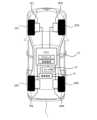
図1は、実施の形態1に係る車両1の構成の一例を概略的に示す図である。車両1は、車輪2とサスペンション3とを備えている。車輪2は、左前輪2FL、右前輪2FR、左後輪2RL、及び右後輪2RRを含んでいる。それら左前輪2FL、右前輪2FR、左後輪2RL、及び右後輪2RRのそれぞれに対してサスペンション3FL、3FR、3RL、及び3RRが設けられている。以下の説明では、特に区別の必要が無い場合、各車輪を車輪2と呼び、各サスペンションをサスペンション3と呼ぶ。1. First embodiment
1-1. Example of Vehicle Configuration Fig. 1 is a diagram that shows a schematic example of the configuration of a
図2は、実施の形態1に係るサスペンション3の構成例を示す概念図である。サスペンション3は、車両1のばね下構造体4とばね上構造体5との間を連結するように設けられている。ばね下構造体4は、車輪2を含んでいる。ばね上構造体5は、車体6を含んでいる。サスペンション3は、スプリング3S、ダンパ(ショックアブソーバ)3D、及びアクチュエータ3Aを含んでいる。スプリング3S、ダンパ3D、及びアクチュエータ3Aは、ばね下構造体4とばね上構造体5との間に並列に設けられている。スプリング3Sのばね定数はKである。ダンパ3Dの減衰係数はCである。また、サスペンション3は、バンプラバー(バンプストッパ)3Bを含んでいる。バンプラバー3Bは、ダンパ3Dと同心に設けられている。Figure 2 is a conceptual diagram showing an example of the configuration of the
アクチュエータ3Aは、ばね下構造体4とばね上構造体5との間に上下方向の制御力Fcを作用させることにより、サスペンション3のストロークSTを制御する。アクチュエータ3Aは、例えば、電動式又は油圧式のアクティブアクチュエータ(いわゆる、フルアクティブサスペンションを構成するアクチュエータ)である。あるいは、アクチュエータ3Aは、例えば、ダンパ3Dが発生させる減衰力を可変とするアクチュエータ、又は、アクティブスタビライザ装置のアクチュエータであってもよい。The
さらに、車両1は、電子制御ユニット(ECU)10を備えている。ECU10は、プロセッサ、記憶装置、及び入出力インターフェースを備えている。入出力インターフェースは、車両1に取り付けられたセンサ類12からセンサ信号を取り込むとともに、アクチュエータ3Aに対して操作信号を出力する。記憶装置には、アクチュエータ3Aを制御するための各種の制御プログラムが記憶されている。プロセッサは、制御プログラムを記憶装置から読み出して実行し、これにより、アクチュエータ3Aを利用したサスペンション制御(後述の乗心地制御及び姿勢制御を含む)が実現される。The
センサ類12は、例えば、車両1に作用する横加速度LA及び前後加速度FAをそれぞれ検出する加速度センサ、ばね上構造体5の上下加速度を検出するばね上加速度センサ、サスペンションストロークセンサ、並びに、各車輪2に設けられた車輪速センサを含む。車輪速センサによれば、車速Vを検出できる。また、センサ類12は、例えば、アクセルペダル及びブレーキペダルの踏み込み量をそれぞれ検出するアクセルポジションセンサ及びブレーキポジションセンサ、並びに、車輪2の舵角センサを含む。さらに、センサ類12は、車両1の位置及び方位を検出する位置センサを含む。当該位置センサは、例えば、GNSS(Global Navigation Satellite System)受信機を含んでいる。The
また、車両1は通信装置14を備える。ECU10は、通信装置14を介して車両1の外部と通信を行う。The
1-2.サスペンション制御
車両1のサスペンション制御は、「路面入力に対する乗心地制御」と、「車両操作入力に対する姿勢制御」とを含む。1-2. Suspension Control The suspension control of the
1-2-1.乗心地制御
路面入力に対する乗心地制御は、路面入力に対するばね上構造体5の振動(より詳細には、上下振動)を低減するために実行される。乗心地制御は、車両1の乗り心地の改善のために、路面入力に伴うばね上構造体5の挙動の変化を抑制する制御ということもできる。1-2-1. Ride comfort control The ride comfort control for a road input is executed to reduce vibration (more specifically, vertical vibration) of the sprung structure 5 in response to the road input. The ride comfort control can also be said to be control that suppresses changes in the behavior of the sprung structure 5 associated with the road input in order to improve the ride comfort of the
乗心地制御は、例えば、車両前方の路面情報に基づくプレビュー制御である。図3は、プレビュー制御を説明するための概念図である。車両前方の路面情報は、例えば、車両1が通信装置14を介してクラウド上の管理サーバから路面データマップとして取得することができる。この路面データマップは、路面の上下方向の変位Zr(図2参照)に関連する路面変位関連値をデータ記憶位置(地図上の位置)と関連付けてマップ化したものである。路面変位関連値としては、上記の路面変位Zr、路面変位Zrの時間微分値である路面変位速度Zr’、ばね下変位Zu、ばね下速度Zu'、ばね下加速度Zu''、ばね上変位Zs、ばね上速度Zs'、ばね上加速度Zs''、等が例示される。そして、路面データマップの具体例は、路面変位関連値の一例としてばね下変位Zu(図2参照)を用いるばね下変位マップである。なお、路面データマップの生成及び更新は、車両1を含む多数の車両から収集した情報に基づいて事前に行われている。なお、車両前方の路面情報は、路面データマップを利用した取得に代え、例えば、車両前方に搭載されたカメラにより撮影される画像を利用して取得されてもよい。The ride comfort control is, for example, a preview control based on road surface information ahead of the vehicle. FIG. 3 is a conceptual diagram for explaining the preview control. The road surface information ahead of the vehicle can be obtained, for example, by the
プレビュー制御において、ECU10は、各車輪2の現在位置P0を取得する。車両1における車両位置の基準点と各車輪2との間の相対位置関係は既知情報である。その相対位置関係と位置情報で示される車両位置に基づいて、各車輪2の位置を算出することができる。ここでいう位置情報は、例えば、センサ類12に含まれる位置センサを用いて取得される。また、位置情報は、デッドレコニングによって取得されてもよい。In the preview control, the
ECU10は、プレビュー時間tp後の車輪2の予測通過位置Pfを算出する。プレビュー時間tpは、例えば、サスペンション3のアクチュエータ3Aを作動させるまでに必要な計算処理や通信処理に要する時間以上に設定される。プレビュー時間tpは、固定であってもよいし、状況に応じて可変であってもよい。プレビュー距離Lpは、プレビュー時間tpと車速Vの積により与えられる。予測通過位置Pfは、現在位置P0からプレビュー距離Lpだけ前方の位置である。変形例として、ECU10は、車速Vと車輪2の舵角に基づいて予想走行ルートを算出し、予想走行ルートに基づいて予測通過位置Pfを算出してもよい。The
ECU10は、予測通過位置Pfにおけるばね下変位Zuをばね下変位マップから読み出す。そして、ECU10は、予測通過位置Pfにおけるばね下変位Zuに基づいて、サスペンション3のアクチュエータ3Aの目標制御力Fc_tを算出する。目標制御力Fc_tは、例えば、次のように算出される。この目標制御力Fc_tは、プレビュー制御のために必要とされる制御力Fcの要求値(すなわち、後述の要求制御量Xpv)に相当する。The
ばね上構造体5(図2参照)に関する運動方程式は、次の式(1)により表される。
m・Zs''=C(Zu'-Zs')+K(Zu-Zs)-Fc ・・・(1) The equation of motion for the sprung structure 5 (see FIG. 2) is expressed by the following equation (1).
m・Zs''=C(Zu'-Zs')+K(Zu-Zs)-Fc...(1)
式(1)において、mはばね上構造体5の質量であり、Zsはばね上変位であり、Cはダンパ3Dの減衰係数であり、Kはスプリング3Sのばね定数であり、Fcはアクチュエータ3Aが発生させる上下方向の制御力である。仮に、制御力Fcによってばね上構造体5の振動が完全に打ち消される場合(Zs''=0,Zs'=0,Zs=0)、その制御力Fcは次の式(2)により表される。
Fc=C・Zu'+K・Zu ・・・(2) In formula (1), m is the mass of the sprung structure 5, Zs is the sprung displacement, C is the damping coefficient of the
Fc=C・Zu'+K・Zu...(2)
少なくとも制振効果をもたらす制御力Fcは、次の式(3)により表される。
Fc=α・C・Zu'+β・K・Zu ・・・(3) A control force Fc that provides at least a vibration damping effect is expressed by the following equation (3).
Fc=α・C・Zu'+β・K・Zu...(3)
式(3)において、制御ゲインαは、0より大きく且つ1以下であり、制御ゲインβも、0より大きく且つ1以下である。式(3)中の微分項を省略した場合、少なくとも制振効果をもたらす制御力Fcは、次の式(4)により表される。
Fc=β・K・Zu ・・・(4) In formula (3), the control gain α is greater than 0 and less than or equal to 1, and the control gain β is also greater than 0 and less than or equal to 1. When the differential term in formula (3) is omitted, a control force Fc that provides at least a vibration damping effect is expressed by the following formula (4).
Fc=β・K・Zu...(4)
ECU10は、上記式(3)あるいは式(4)に従って、目標制御力Fc_t(すなわち、要求制御量Xpv)を算出する。すなわち、ECU10は、予測通過位置Pfにおけるばね下変位Zuを式(3)あるいは式(4)に代入して、目標制御力Fc_t(要求制御量Xpv)を算出する。The
ECU10は、車輪2が予測通過位置Pfを通過するタイミングで目標制御力Fc_t(要求制御量Xpv)を発生させるようにアクチュエータ3Aを制御する。車輪2が予測通過位置Pfを通過するタイミングはプレビュー時間tpから分かる。The
以上に説明されたプレビュー制御によれば、車両1(ばね上構造体5)の振動を効果的に抑制することが可能となる。The preview control described above makes it possible to effectively suppress vibrations of the vehicle 1 (sprung structure 5).
乗心地制御は、プレビュー制御に代え、あるいはそれとともに、例えば、ばね上変位Zs、ばね上速度Zs’、及びばね上加速度Zs’’の少なくとも1つを用いてばね上構造体5の振動を低減するためのスカイフック制御則に基づくフィードバック制御(例えば、特開2019-135120号公報参照)であってもよい。また、ばね上構造体5の振動を低減するためのスカイフック制御則に基づくフィードバック制御は、ばね下構造体4の状態量(ばね下変位Zu、ばね下速度Zu’、及びばね下加速度Zu’’の少なくとも1つ)に比例した出力(制御力Fc)を発生させるものであってもよい。The ride comfort control may be, instead of or in addition to the preview control, feedback control based on the skyhook control law for reducing vibration of the sprung structure 5 using at least one of the sprung displacement Zs, the sprung velocity Zs', and the sprung acceleration Zs'' (see, for example, JP 2019-135120 A). In addition, the feedback control based on the skyhook control law for reducing vibration of the sprung structure 5 may generate an output (control force Fc) proportional to the state quantity of the unsprung structure 4 (at least one of the unsprung displacement Zu, the unsprung velocity Zu', and the unsprung acceleration Zu'').
1-2-2.姿勢制御
車両操作入力に対する姿勢制御は、車両1の操舵に伴う旋回時のロール制御、及び車両1の加減速に伴うピッチ制御の少なくとも一方を含む。本実施形態では、姿勢制御として、ロール制御及びピッチ制御が組み合わされて実行されているものとする。このような例に代え、ロール制御及びピッチ制御の何れか一方のみが姿勢制御として実行されてもよい。1-2-2. Attitude Control Attitude control in response to a vehicle operation input includes at least one of roll control during turning associated with steering of the
ここでいうロール制御とは、車両1の操舵に伴う旋回時に生じるロールを打ち消すように、アクチュエータ3Aの制御力Fcを制御して逆ロールモーメントを発生させる制御のことである。より詳細には、「ロールを打ち消す」とは、ロール制御なしの場合と比べて発生するロールを抑制したり、発生するロールと逆方向のロールを発生させたりすることをいう。同様に、ここでいうピッチ制御とは、車両1の加減速時に生じるピッチを打ち消すように、アクチュエータ3Aの制御力Fcを制御して逆ピッチモーメントを発生させる制御のことである。より詳細には、「ピッチを打ち消す」とは、ピッチ制御なしの場合と比べて発生するピッチを抑制したり、発生するピッチと逆方向のピッチを発生させたりすることをいう。The roll control referred to here is control that controls the control force Fc of the
なお、各車輪2において、サスペンション発生力である制御力Fcは、ばね上構造体5を上方に持ち上げるように作用する時に正とする。これに伴い、サスペンション制御の各要求制御量(例えば、Xr、Xp、及びXpv)も、ばね上構造体5を上方に持ち上げるように作用する時に正となる。したがって、ロール要求制御量Xrは、旋回外側の車輪2では正となり、旋回内側の車輪2では負となる。同様に、ピッチ要求制御量Xpは、加速時には、前輪2FL及び2FRでは負となり、後輪2RL及び2RRでは正となり、逆に、減速時には、前輪2FL及び2FRでは正となり、後輪2RL及び2RRでは負となる。Note that, for each
1-2-3.ECUによる処理
実施の形態1では、路面状態を考慮しつつ乗心地制御と姿勢制御とを両立させるために、ECU10による処理は、次のような「算出処理」及び「調停処理」を含む。すなわち、ECU10は、路面入力に対する乗心地制御のための第1要求制御量X1を算出する第1算出処理と、車両操作入力に対する姿勢制御のための第2要求制御量X2を算出する第2算出処理と、を実行する。そして、ECU10は、算出した第1要求制御量X1と第2要求制御量X2との和(すなわち、合計の要求制御量Xt(=X1+X2))がアクチュエータ3Aによって出力可能な制御量範囲Rxを超える場合、路面入力情報に基づいて第2要求制御量X2を小さく制限する調停処理を実行する。1-2-3. Processing by ECU In the first embodiment, in order to achieve both ride comfort control and attitude control while taking into account the road surface condition, the processing by the
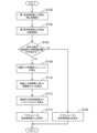
図4は、実施の形態1に係るサスペンション制御に関する処理を示すフローチャートである。このフローチャートの処理は、車両1の走行中に、所定の時間ステップ毎に繰り返し実行される。なお、図4では、ステップS100の処理が上述の「第1算出処理」の一例に相当し、ステップS102の処理が上述の「第2算出処理」の一例に相当し、ステップS104、S108、及びS110の処理が上述の「調停処理」の一例に相当する。Figure 4 is a flowchart showing processing related to suspension control according to the first embodiment. The processing of this flowchart is repeatedly executed at predetermined time steps while the
<ステップS100>
ステップS100において、ECU10は、乗心地制御のための第1要求制御量X1を算出する。乗り心地制御の制御則は特に限定されず、したがって第1要求制御量X1の算出手法も特に限定されない。本実施形態では、乗心地制御の一例としてプレビュー制御が実行されているものとする。このため、ECU10は、プレビュー制御のための上述の要求制御量Xpv(目標制御力Fc_t)を第1要求制御量X1として算出する。第1要求制御量X1の算出は、アクチュエータ3Aが配置されている車輪2毎に行われる。<Step S100>
In step S100, the
なお、例えば、複数の乗り心地制御(例えば、プレビュー制御と、上述のスカイフック制御則に基づくフィードバック制御)が実行されている例では、実行されている複数の乗り心地制御の要求制御量の和が第1要求制御量X1として算出される。Note that, for example, in an example in which multiple ride comfort controls (e.g., preview control and feedback control based on the above-mentioned skyhook control law) are being executed, the sum of the required control amounts of the multiple ride comfort controls being executed is calculated as the first required control amount X1.
<ステップS102>
ステップS102において、ECU10は、姿勢制御のための第2要求制御量X2を算出する。姿勢制御の制御則は特に限定されず、したがって第2要求制御量X2の算出手法も特に限定されない。姿勢制御としてロール制御及びピッチ制御が実行される本実施形態では、ECU10は、ロール要求制御量Xrとピッチ要求制御量Xpとの和を第2要求制御量X2として算出する。第2要求制御量X2の算出は、アクチュエータ3Aが配置されている車輪2毎に行われる。<Step S102>
In step S102, the
具体的には、ロール要求制御量Xrは、ロール制御のために必要とされる制御力Fcの要求値に相当する。ピッチ要求制御量Xpは、ピッチ制御のために必要とされる制御力Fcの要求値に相当する。一例として、ロール要求制御量Xr及びピッチ要求制御量Xpは、それぞれ、次の式(5)及び(6)により表される。
Xr=LA×Gr ・・・(5)
Xp=FA×Gp ・・・(6) Specifically, the roll required control amount Xr corresponds to a required value of the control force Fc required for roll control. The pitch required control amount Xp corresponds to a required value of the control force Fc required for pitch control. As an example, the roll required control amount Xr and the pitch required control amount Xp are expressed by the following equations (5) and (6), respectively.
Xr=LA×Gr...(5)
Xp=FA×Gp...(6)
式(5)に示すように、ロール要求制御量Xrは、横加速度LAと制御ゲインGrとの積により与えられる。式(6)に示すように、ピッチ要求制御量Xpは、前後加速度FAと制御ゲインGpとの積により与えられる。なお、ロール制御用の制御ゲインGrとピッチ制御用の制御ゲインGpは、同じでもよいし、異なっていてもよい。これらの制御ゲインGr及びGpは、後述の制御ゲインG2に相当する。As shown in equation (5), the roll required control amount Xr is given by the product of the lateral acceleration LA and the control gain Gr. As shown in equation (6), the pitch required control amount Xp is given by the product of the longitudinal acceleration FA and the control gain Gp. The control gain Gr for roll control and the control gain Gp for pitch control may be the same or different. These control gains Gr and Gp correspond to the control gain G2 described below.
式(5)により算出されるロール要求制御量Xrによれば、横加速度LAの絶対値が大きくなるにつれ、ロール要求制御量Xrの絶対値も大きくなる。制御ゲインGrは、例えば事前に決定された固定値である。ただし、制御ゲインGrは、車両姿勢制御に関連するパラメータに応じて可変であってもよい。横加速度LAは、例えば横加速度センサを用いて取得できる。また、横加速度LAは、例えば、車速V及び舵角等の情報に基づいて推定されてもよい。According to the roll request control amount Xr calculated by the formula (5), as the absolute value of the lateral acceleration LA increases, the absolute value of the roll request control amount Xr also increases. The control gain Gr is, for example, a fixed value determined in advance. However, the control gain Gr may be variable depending on parameters related to the vehicle attitude control. The lateral acceleration LA can be obtained, for example, by using a lateral acceleration sensor. Furthermore, the lateral acceleration LA may be estimated, for example, based on information such as the vehicle speed V and the steering angle.
また、式(6)により算出されるピッチ要求制御量Xpによれば、前後加速度FAの絶対値が大きくなるにつれ、ピッチ要求制御量Xpの絶対値も大きくなる。制御ゲインGpは、例えば事前に決定された固定値である。ただし、制御ゲインGpは、車両姿勢制御に関連するパラメータに応じて可変であってもよい。前後加速度FAは、例えば前後加速度センサを用いて取得できる。また、前後加速度FAは、例えば、車両前後力の要求情報(例えば、要求エンジントルク、又は要求制動力)に基づいて推定されてもよい。Furthermore, according to the pitch required control amount Xp calculated by equation (6), as the absolute value of the longitudinal acceleration FA increases, the absolute value of the pitch required control amount Xp also increases. The control gain Gp is, for example, a fixed value determined in advance. However, the control gain Gp may be variable depending on parameters related to vehicle attitude control. The longitudinal acceleration FA can be acquired, for example, using a longitudinal acceleration sensor. Furthermore, the longitudinal acceleration FA may be estimated, for example, based on required information of the vehicle longitudinal force (for example, required engine torque or required braking force).
<ステップS104>
ステップS104において、ECU10は、ステップS100及びS102にて算出した第1要求制御量X1と第2要求制御量X2との和である合計の要求制御量Xtがアクチュエータ3Aによって出力可能な制御量範囲Rxを超えるか否かを判定する。この制御量範囲Rxは、アクチュエータ3Aのスペックに基づいて事前に特定できる。要求制御量Xtが制御量範囲Rxを超えない場合には、処理はステップS106に進む。一方、要求制御量Xtが制御量範囲Rxを超える場合には、処理はステップS108に進む。<Step S104>
In step S104, the
<ステップS106>
ステップS104の判定結果がNoの場合(すなわち、アクチュエータ3Aが要求制御量Xtを出力可能な場合)には、ステップS106において、ECU10は、要求制御量Xtをそのまま(すなわち、制限なしに)アクチュエータ3Aに指令する処理を、車輪2毎に実行する。その結果、各アクチュエータ3Aは、指令された要求制御量Xtに応じた制御力Fcを発生させるように制御される。<Step S106>
If the determination result in step S104 is No (i.e., if the
<ステップS108>
一方、ステップS104の判定結果がYesの場合(すなわち、アクチュエータ3Aが要求制御量Xtを出力できない場合)、ステップS108において、ECU10は、路面入力指標値I(単に「指標値I」とも称する)を算出する。指標値Iは、本開示に係る「路面入力情報」の一例に相当する。<Step S108>
On the other hand, if the determination result in step S104 is Yes (i.e., if the
具体的には、指標値Iは、例えば、路面入力の大きさを示す指標値Im、路面入力速度の大きさを示す指標値Iv、及び、路面入力の高周波成分の大きさを示す指標値Ifを含む。本ステップS108において算出される指標値Iは、これらの指標値Im、Iv、及びIfのうちの何れか1つであってもよいし、何れか2つ又は3つであってもよい。各指標値Im、Iv、及びIfの算出手法は特に限定されるものではないが、各指標値Im、Iv、及びIfは、例えば次のような手法を用いて算出できる。Specifically, the index value I includes, for example, an index value Im indicating the magnitude of the road surface input, an index value Iv indicating the magnitude of the road surface input speed, and an index value If indicating the magnitude of the high-frequency component of the road surface input. The index value I calculated in this step S108 may be any one of these index values Im, Iv, and If, or any two or three of them. The calculation method of each of the index values Im, Iv, and If is not particularly limited, but each of the index values Im, Iv, and If can be calculated using, for example, the following method.
(指標値Imについて)
路面入力の大きさには、より具体的には、ばね下変位Zuの大きさ、又は路面変位Zrの大きさが相当する。したがって、指標値Imの具体例は、ばね下変位Zu又は路面変位Zrの大きさを示す値である。本実施形態のようにプレビュー制御を行っている場合であれば、指標値Imは、プレビュー制御において取得されるばね下変位Zu又は路面変位Zrを基に算出されてもよい。あるいは、プレビュー制御が実行される場合を含め、指標値Imに用いられるばね下変位Zuは、ばね下変位センサを用いて直接的に計測されてもよく、又は他のセンサの計測値に基づいて算出(推定)されてもよい。指標値Imに用いられる路面変位Zrは、例えば、車両前方に搭載されたカメラにより撮影される画像を利用して取得されてもよい。(Regarding the index value Im)
More specifically, the magnitude of the road surface input corresponds to the magnitude of the unsprung displacement Zu or the magnitude of the road surface displacement Zr. Therefore, a specific example of the index value Im is a value indicating the magnitude of the unsprung displacement Zu or the road surface displacement Zr. When the preview control is performed as in this embodiment, the index value Im may be calculated based on the unsprung displacement Zu or the road surface displacement Zr acquired in the preview control. Alternatively, including the case where the preview control is performed, the unsprung displacement Zu used in the index value Im may be directly measured using an unsprung displacement sensor, or may be calculated (estimated) based on the measurement value of another sensor. The road surface displacement Zr used in the index value Im may be acquired, for example, by using an image captured by a camera mounted in front of the vehicle.
また、例えば、車両進行方向に沿った所定のデータ取得区間のばね下変位Zu又は路面変位Zrのデータ(時間、距離、又は位置ベースのデータ)のp-p値(peak to peak)又は移動平均値が、指標値Imとして算出されてもよい。また、ローパスフィルタ(LPF)のカットオフ周波数を十分に小さくすると、LPF処理の適用後の値は、移動平均値に相当する値とみなせる。このため、上記のデータ取得区間のばね下変位Zu又は路面変位Zrのデータに対してこのようなLPFを適用した後の値が指標値Imとして算出されてもよい。For example, the p-p value (peak to peak) or moving average value of the data (time, distance, or position-based data) of the unsprung displacement Zu or road surface displacement Zr in a specified data acquisition section along the vehicle travel direction may be calculated as the index value Im. Furthermore, if the cutoff frequency of the low-pass filter (LPF) is made sufficiently small, the value after application of the LPF process can be regarded as a value equivalent to the moving average value. For this reason, the value after applying such an LPF to the data of the unsprung displacement Zu or road surface displacement Zr in the above data acquisition section may be calculated as the index value Im.
(指標値Ivについて)
路面入力速度の大きさには、より具体的には、ばね下速度Zu’の大きさ、又は路面変位速度Zr’の大きさが相当する。したがって、指標値Ivの具体例は、ばね下速度Zu’又は路面変位速度Zr’の大きさを示す値である。ばね下速度Zu’又は路面変位速度Zr’のデータに基づく指標値Ivの算出は、上述の指標値Imの算出手法と同様の手法を用いて行うことができる。(Regarding index value Iv)
More specifically, the magnitude of the road surface input velocity corresponds to the magnitude of the unsprung velocity Zu' or the magnitude of the road surface displacement velocity Zr'. Therefore, a specific example of the index value Iv is a value indicating the magnitude of the unsprung velocity Zu' or the road surface displacement velocity Zr'. The calculation of the index value Iv based on the data of the unsprung velocity Zu' or the road surface displacement velocity Zr' can be performed using a method similar to the calculation method of the index value Im described above.
(指標値Ifについて)
路面入力の高周波成分の大きさには、より具体的には、車両進行方向に沿った所定のデータ取得区間のばね下変位Zu又は路面変位Zrのデータの高周波成分の大きさが相当する。したがって、指標値Ifの具体例は、ばね下変位Zu又は路面変位Zrのデータの高周波成分の大きさを示す値(例えば、信号強度)である。ここでいう高周波成分は、例えば、所定周波数値(所定カットオフ周波数)以上の周波数領域の周波数成分として特定される。(Regarding the index value If)
More specifically, the magnitude of the high-frequency component of the road surface input corresponds to the magnitude of the high-frequency component of the data of the unsprung displacement Zu or the road surface displacement Zr in a predetermined data acquisition section along the vehicle travel direction. Therefore, a specific example of the index value If is a value (e.g., signal strength) indicating the magnitude of the high-frequency component of the data of the unsprung displacement Zu or the road surface displacement Zr. The high-frequency component here is specified as, for example, a frequency component in a frequency range equal to or higher than a predetermined frequency value (predetermined cutoff frequency).
このような指標値Ifは、例えば、ECU10が上記のばね下変位Zu又は路面変位Zrのデータに対して高速フーリエ変換(FFT)処理を行うことによって取得される周波数スペクトルに基づいて算出できる。あるいは、例えば、当該データに対してバンドパスフィルタ(BPF)処理又はハイパスフィルタ(HPF)処理を適用した後の出力データの移動平均値が指標値Ifとして取得されてもよい。また、この出力データに対してカットオフ周波数が十分に小さいLPFを適用した後の値が指標値Ifとして取得されてもよい。Such an index value If can be calculated, for example, based on a frequency spectrum obtained by the
(第1要求制御量X1の利用)
乗心地制御の第1要求制御量X1は、基本的には、算出手法を問わず、路面入力情報に応じた値として算出されるものであるといえる。より詳細には、第1要求制御量X1は、路面入力が大きくなると、第1要求制御量X1も大きくなる。路面入力速度が高くなると、第1要求制御量X1の変化速度も高くなる。そして、路面入力の高周波成分が大きくなると、第1要求制御量X1の高周波成分も大きくなる。(Use of first required control amount X1)
Basically, the first required control amount X1 of the ride comfort control is calculated as a value corresponding to the road surface input information, regardless of the calculation method. More specifically, the first required control amount X1 increases as the road surface input increases. As the road surface input speed increases, the rate of change of the first required control amount X1 also increases. Furthermore, as the high-frequency components of the road surface input increase, the high-frequency components of the first required control amount X1 also increase.
そこで、指標値Im及びIfのそれぞれの算出のために、ばね下変位Zu又は路面変位Zrのデータに代えて第1要求制御量X1のデータが用いられてもよい。また、指標値Ivの算出のために、ばね下速度Zu’又は路面変位速度Zr’のデータに代えて第1要求制御量X1のデータが用いられてもよい。Therefore, data on the first required control amount X1 may be used instead of data on the unsprung displacement Zu or road surface displacement Zr to calculate the index value Im and If, respectively. Also, data on the first required control amount X1 may be used instead of data on the unsprung velocity Zu' or road surface displacement velocity Zr' to calculate the index value Iv.
<ステップS110>
ステップS110において、ECU10は、路面入力情報(路面入力指標値I)に基づく制限後の第2要求制御量X2である制限値X2lmtを算出する。制限値X2lmtの算出のために用いられる指標値Iは、指標値Im、Iv、及びIfのうちの何れか1つであってもよいし、何れか2つ又は3つであってもよい。<Step S110>
In step S110, the
図5(A)、5(B)、及び5(C)は、それぞれ、指標値Im、Iv、及びIfに基づく制限値X2lmtの算出手法の一例を説明するための図である。制限値X2lmtは、次のように、制限値G2lmtを用いて姿勢制御の制御ゲインG2を修正することによって算出される。図5に示す手法が用いられる前提として、制御ゲインG2(Gr及びGp)は固定値であるものとする。なお、制御ゲインG2が姿勢制御に関係するパラメータに基づいて可変される例では、ECU10は、図5の縦軸を修正係数k1(0≦k1≦1)によって置き換え、且つ、修正前の制御ゲインG2に当該修正係数k1を乗じることによって制限値G2lmtを算出してもよい。Figures 5(A), 5(B), and 5(C) are diagrams for explaining an example of a calculation method of the limit value X2lmt based on the index values Im, Iv, and If, respectively. The limit value X2lmt is calculated by modifying the control gain G2 of the posture control using the limit value G2lmt as follows. As a prerequisite for using the method shown in Figure 5, the control gain G2 (Gr and Gp) is assumed to be a fixed value. In an example in which the control gain G2 is varied based on a parameter related to posture control, the
図5を参照して説明される算出手法では、姿勢制御の制御ゲインG2が路面入力情報(指標値I)に基づいて制限値G2lmtに修正される。なお、本実施形態のようにロール制御及びピッチ制御の双方が姿勢制御として実行される場合、例えば、制御ゲインG2に相当する制御ゲインGr及びGpのそれぞれが、図5を参照して説明されるように修正されることになる。In the calculation method described with reference to FIG. 5, the control gain G2 of the posture control is corrected to a limit value G2lmt based on the road surface input information (index value I). Note that when both roll control and pitch control are executed as posture control as in this embodiment, for example, each of the control gains Gr and Gp corresponding to the control gain G2 is corrected as described with reference to FIG. 5.
具体的には、指標値Imを用いる例では、図5(A)に示すように、制限値G2lmtは、指標値Imが大きいほど小さくなるように算出される。その結果、制御ゲインG2は、指標値Imが大きいほど(すなわち、路面入力が大きいほど)小さくなるように修正される。付け加えると、図5(A)には表されていないが、指標値Imの増加に応じた制御ゲインG2の修正は、制限値G2lmtをゼロにすることを含んでもよい。制限値G2lmtがゼロであることは、姿勢制御が中止されることを意味する。Specifically, in an example using the index value Im, as shown in FIG. 5(A), the limit value G2lmt is calculated to be smaller as the index value Im increases. As a result, the control gain G2 is modified to be smaller as the index value Im increases (i.e., as the road surface input increases). In addition, although not shown in FIG. 5(A), the modification of the control gain G2 in response to an increase in the index value Im may include setting the limit value G2lmt to zero. The limit value G2lmt being zero means that posture control is discontinued.
指標値Ivを用いる例では、図5(B)に示すように、制限値G2lmtは、指標値Ivが大きいほど小さくなるように算出される。その結果、制御ゲインG2は、指標値Ivが大きいほど(すなわち、路面入力速度が高いほど)小さくなるように修正される。指標値Imの例と同様に、指標値Ivの増加に応じた制御ゲインG2の修正は、制限値G2lmtをゼロにすることを含んでもよい。In an example using the index value Iv, as shown in FIG. 5(B), the limit value G2lmt is calculated to be smaller as the index value Iv increases. As a result, the control gain G2 is modified to be smaller as the index value Iv increases (i.e., as the road surface input speed increases). As in the example using the index value Im, the modification of the control gain G2 in response to an increase in the index value Iv may include setting the limit value G2lmt to zero.
指標値Ifを用いる例では、図5(C)に示すように、制限値G2lmtは、指標値Ifが大きいほど小さくなるように算出される。その結果、制御ゲインG2は、指標値Ifが大きいほど(すなわち、路面入力の高周波成分が大きいほど)小さくなるように修正される。指標値Im及びIvの例と同様に、指標値Ifの増加に応じた制御ゲインG2の修正は、制限値G2lmtをゼロにすることを含んでもよい。In an example using the index value If, as shown in FIG. 5(C), the limit value G2lmt is calculated to be smaller as the index value If increases. As a result, the control gain G2 is modified to be smaller as the index value If increases (i.e., as the high-frequency components of the road surface input increase). As in the example of the index values Im and Iv, the modification of the control gain G2 in response to an increase in the index value If may include setting the limit value G2lmt to zero.
次に、指標値Im、Iv、及びIfのうちの2つ又は3つの組み合わせを利用する例における制限値G2lmtの算出手法の2つの具体例1及び2が説明される。下記の説明では、指標値Imと指標値Ivとの組み合わせが例示されるが、他の2つの組み合わせ又は3つの組み合わせの例についても同様である。Next, two specific examples 1 and 2 of the calculation method of the limit value G2lmt in an example using a combination of two or three of the index values Im, Iv, and If are described. In the following description, a combination of the index value Im and the index value Iv is exemplified, but the same applies to other examples of combinations of two or three.
具体例1では、まず、図5(A)及び5(B)に示す関係を利用して、指標値Im及びIvのそれぞれに基づく制御ゲインG2の減少量(制限量)が算出される。ここでいう減少量とは、修正前の値に対する制御ゲインG2の減少量のことである。次いで、算出された2つの減少量が足し合わされる。次いで、足し合わされた減少量を修正前の制御ゲインG2から引くことにより、制限値G2lmtが算出される。例えば、指標値Imに基づく減少量が制御ゲインG2を2割減らすものであり、指標値Ivに基づく減少量が制御ゲインG2を2割減らすものであった場合、修正前の制御ゲインG2を4割減らした値となるように制限値G2lmtが算出される。In specific example 1, first, the reduction amount (limit amount) of the control gain G2 based on each of the index values Im and Iv is calculated using the relationship shown in Figures 5 (A) and 5 (B). The reduction amount here refers to the reduction amount of the control gain G2 relative to the value before correction. Next, the two calculated reduction amounts are added together. Next, the limit value G2lmt is calculated by subtracting the added reduction amount from the control gain G2 before correction. For example, if the reduction amount based on the index value Im reduces the control gain G2 by 20% and the reduction amount based on the index value Iv reduces the control gain G2 by 20%, the limit value G2lmt is calculated to be a value that reduces the control gain G2 before correction by 40%.
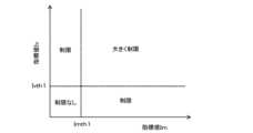
図6は、複数の路面入力指標値I(例えば、ImとIv)の組み合わせを利用した制限値G2lmtの算出手法の具体例2を説明するための図である。具体例2の実施のために、ECU10の記憶装置は、図6に示すような関係をマップとして記憶している。具体例2では、指標値Im及び指標値Ivが、それぞれの閾値Imth1及びIvth1と比較される。Figure 6 is a diagram for explaining a specific example 2 of a method for calculating the limit value G2lmt using a combination of multiple road surface input index values I (e.g., Im and Iv). To implement specific example 2, the storage device of the
その結果、指標値Imが閾値Imth1より小さく、且つ指標値Ivが閾値Ivth1より小さい場合には、制御ゲインG2の修正は行われない。すなわち、乗心地制御を優先する必要がない又は低いと判断され、第2要求制御量X2は制限されない。As a result, if the index value Im is smaller than the threshold value Imth1 and the index value Iv is smaller than the threshold value Ivth1, the control gain G2 is not modified. In other words, it is determined that ride comfort control does not need to be prioritized or is low, and the second required control amount X2 is not limited.
一方、指標値Im及び指標値Ivの何れか一方のみがそれぞれに対応する閾値Imth1又はIvth1以上である場合には、閾値Imth1又はIvth1以上となる方の指標値Im又は指標値Ivに応じて(図5(A)又は5(B)の関係を利用して)、制御ゲインG2が小さくなるように修正される。つまり、乗心地制御を優先すべき状況と判断され、第2要求制御量X2が制限される。On the other hand, if only one of the index value Im and the index value Iv is equal to or greater than the corresponding threshold value Imth1 or Ivth1, the control gain G2 is modified to be smaller according to the index value Im or index value Iv that is equal to or greater than the threshold value Imth1 or Ivth1 (using the relationship in FIG. 5(A) or 5(B)). In other words, it is determined that the situation is one in which ride comfort control should be prioritized, and the second required control amount X2 is restricted.
また、指標値Imが閾値Imth1以上、且つ指標値Ivが閾値Ivth1以上の場合には、指標値Im及び指標値Ivの何れか一方のみがそれぞれに対応する閾値Imth1又はIvth1以上である場合と比べて、制御ゲインG2がより小さくなるように修正される。つまり、乗心地制御をより優先すべき状況であると判断され、第2要求制御量X2がより大きく制限される。In addition, when the index value Im is equal to or greater than the threshold value Imth1 and the index value Iv is equal to or greater than the threshold value Ivth1, the control gain G2 is modified to be smaller than when only one of the index value Im and the index value Iv is equal to or greater than the corresponding threshold value Imth1 or Ivth1. In other words, it is determined that the situation requires higher priority for ride comfort control, and the second required control amount X2 is restricted to a greater extent.
具体例1及び2のそれぞれによれば、指標値Im、Iv、及びIfのうちの複数を考慮して制限値X2lmtを算出することにより、路面入力情報をより正確に考慮できるようになる。その結果、第2要求制御量X2の制限(調整)をより正確に行えるようになる。According to each of specific examples 1 and 2, the limit value X2lmt is calculated by taking into account two or more of the index values Im, Iv, and If, so that the road surface input information can be taken into account more accurately. As a result, the second required control amount X2 can be restricted (adjusted) more accurately.
<ステップS112>
ステップS112において、ECU10は、サスペンション制御の最終的な要求制御量Xfinを算出する。要求制御量Xfinは、ステップS100及びステップS110にてそれぞれ算出された第1要求制御量X1と制限値X2lmtとの和である。<Step S112>
In step S112, the
<ステップS114>
ステップS114において、ECU10は、ステップS112にて算出された要求制御量Xfinをアクチュエータ3Aに指令する処理を、車輪2毎に実行する。その結果、各アクチュエータ3Aは、指令された要求制御量Xfinに応じた制御力Fcを発生させるように制御される。<Step S114>
In step S114, the
1-3.効果
サスペンション制御を行うためのアクチュエータ3Aの出力には限りがある。このため、アクチュエータ3Aが乗心地制御及び姿勢制御の双方の要求制御量X1及びX2の和を出力できない条件下においてこれらの要求制御量X1及びX2を単に足し合わせてアクチュエータ3Aに指令しても、優先することが望ましいどちらか一方の制御を適切に行えず、状況に適したサスペンション制御を満足に行えなくなることがある。また、当該条件下においてどちらか一方の制御のみを選択した場合には、他方の制御ができないため、状況に適したサスペンション制御を満足に行えなくなることがある。1-3. Effect The output of the
これに対し、実施の形態1に係る調停処理によれば、第1要求制御量X1と第2要求制御量X2との和(要求制御量Xt)が制御量範囲Rxを超える場合、路面入力情報(路面入力指標値I)に基づく制限値X2lmtによって、姿勢制御のための第2要求制御量X2が小さく制限される。つまり、このような場合には、乗心地制御が姿勢制御と比べて優先される。付け加えると、乗心地制御を制限するための変更は行われない。これにより、アクチュエータ3Aが乗心地制御及び姿勢制御の双方の要求制御量X1及びX2を共に満たせない条件下において、路面入力情報を考慮して姿勢制御を適切に制限しながら乗心地制御を良好に実施できるようになる。つまり、路面状態を考慮しつつ乗心地制御と姿勢制御とを両立できるようになる。その結果、当該条件下において要求制御量X1及びX2を単に足し合わせてアクチュエータ3Aに指令したり、どちらか一方の制御のみを選択したりする場合と比べて、サスペンション制御を利用して車両1の快適性を向上できる。In contrast, according to the arbitration process of the first embodiment, when the sum of the first required control amount X1 and the second required control amount X2 (required control amount Xt) exceeds the control amount range Rx, the second required control amount X2 for the posture control is limited to a small value by the limit value X2lmt based on the road surface input information (road surface input index value I). In other words, in such a case, the ride comfort control is prioritized over the posture control. In addition, no change is made to limit the ride comfort control. As a result, under conditions in which the
より具体的には、路面入力が大きい場合には、路面入力が小さい場合と比べて、乗心地制御のために高い出力が必要とされる。実施の形態1によれば、制御ゲインG2は、指標値Imが大きいほど小さくなるように算出される。このように制御ゲインG2が調整されることにより、路面入力が大きいほど姿勢制御のための第2要求制御量X2が小さくなるように、路面状態を考慮して姿勢制御を適切に制限できる(換言すると、乗心地制御を適切に優先できる)ようになる。More specifically, when the road surface input is large, a higher output is required for ride comfort control compared to when the road surface input is small. According to the first embodiment, the control gain G2 is calculated so that it is smaller as the index value Im is larger. By adjusting the control gain G2 in this manner, it becomes possible to appropriately limit posture control in consideration of the road surface conditions (in other words, it becomes possible to appropriately prioritize ride comfort control) so that the second required control amount X2 for posture control becomes smaller as the road surface input is larger.
また、路面入力速度が高い場合には、路面入力速度が低い場合と比べて、高い応答性が乗り心地制御に求められる。実施の形態1によれば、制御ゲインG2は、指標値Ivが大きいほど小さくなるように算出される。このように制御ゲインG2が調整されることにより、路面入力速度が高いほど姿勢制御のための第2要求制御量X2が小さくなるように、路面状態を考慮して姿勢制御を適切に制限できる(換言すると、乗心地制御を適切に優先できる)ようになる。付け加えると、乗心地制御のために確保されるアクチュエータ3Aの出力が増えると、アクチュエータ3Aは、高い応答性で出力(制御力Fc)を発生させられるようになる。Furthermore, when the road input speed is high, higher responsiveness is required for the ride comfort control compared to when the road input speed is low. According to the first embodiment, the control gain G2 is calculated so that it decreases as the index value Iv increases. By adjusting the control gain G2 in this manner, it becomes possible to appropriately limit the posture control taking into account the road surface conditions (in other words, it becomes possible to appropriately prioritize the ride comfort control) so that the second required control amount X2 for posture control decreases as the road input speed increases. In addition, when the output of the
さらに、路面入力の高周波成分が大きい場合には、当該高周波成分が小さい場合にと比べて、高い応答性が乗り心地制御に求められる。実施の形態1によれば、制御ゲインG2は、指標値Ivが大きいほど小さくなるように算出される。このように制御ゲインG2が調整されることにより、路面入力の高周波成分が大きいほど姿勢制御のための第2要求制御量X2が小さくなるように、路面状態を考慮して姿勢制御を適切に制限できる(換言すると、乗心地制御を適切に優先できる)ようになる。Furthermore, when the high-frequency components of the road surface input are large, higher responsiveness is required for the ride comfort control compared to when the high-frequency components are small. According to the first embodiment, the control gain G2 is calculated so that it decreases as the index value Iv increases. By adjusting the control gain G2 in this manner, it becomes possible to appropriately limit the posture control taking into account the road surface conditions (in other words, it becomes possible to appropriately prioritize the ride comfort control) so that the second required control amount X2 for posture control decreases as the high-frequency components of the road surface input increase.
1-4.サスペンションバネ特性に基づく制限
実施の形態1に係る第2要求制御量X2の制限は、路面入力情報とともにサスペンション3のバネ特性を考慮して行われてもよい。1-4. Limitation Based on Suspension Spring Characteristics The limitation of the second required control amount X2 according to the first embodiment may be performed taking into consideration the spring characteristics of the
図7は、図2に示すサスペンション3のバネ特性を表した図である。より詳細には、図7は、サスペンション3の荷重-ストローク特性を示している。図7中のストロークST1は、車両1が静止している状態(すなわち、車体6に作用する重力加速度が1Gの状態)におけるストロークSTの値に相当する。例えば旋回時の外輪では、横加速度LAの増加に伴ってバンプストップクリアランスが減少するようにストロークSTが変化すると、やがてダンパ3D(のケース)がバンプラバー3Bに当たることになる。ストロークST2は、当該ケースがバンプラバー3Bに当たり始める時のストロークSTの値に相当する。Figure 7 shows the spring characteristics of the
図7に示すバネ特性においてストロークST1からストロークST2までのストローク域は、ストロークSTに比例して荷重が大きくなる線形域(スプリング3Sがバネ力を発生される領域)に相当する。スプリング3Sだけでなく、バンプラバー3Bもバネとして機能する。このため、図7に示すバネ特性においてストロークST2よりも大きなストローク域は、ストロークSTに応じてバネ定数が変化する非線形域に相当する。この非線形域では、線形域と比べて、ストロークSTの変化に対して荷重が大きく変化する。In the spring characteristics shown in FIG. 7, the stroke region from stroke ST1 to stroke ST2 corresponds to a linear region (region in which spring force is generated by
サスペンション3が非線形域までストロークすると、乗り心地が低下する。このような乗り心地の低下を回避するためには、ダンパ3Dがバンプラバー3Bと当たらないようにアクチュエータ3Aの出力を姿勢制御(ロール制御及びピッチ制御)のために十分に確保したい。しかしながら、姿勢制御のために確保される出力を増やすことは、乗心地制御のために確保される出力が減少することにつながる。すなわち、アクチュエータ3Aが乗心地制御のために十分な出力及び応答性を発揮させにくくなる。When the
(第1の例)
そこで、バネ特性に基づく制限に関する第1の例では、ECU10は、上述の指標値Im(路面入力の大きさ)が所定の閾値Imth2以上である場合、サスペンション3のバネ特性に基づいて第2要求制御量X2を小さく制限する。具体的には、当該バネ特性に基づく第2要求制御量X2の制限の一例として、ECU10は、操舵に伴うロール角及び加減速に伴うピッチ角のそれぞれがゼロとなるように制御ゲインG2を変更する。(First Example)
Therefore, in a first example of a restriction based on the spring characteristic, when the above-mentioned index value Im (magnitude of road surface input) is equal to or greater than a predetermined threshold value Imth2, the
図8は、サスペンションバネ特性に基づく制限に関する第1の例に係るサスペンション制御に関する処理を示すフローチャートである。このフローチャートの処理は、ステップS108及びS110の処理に代えて、ステップS200及びS202の処理が「調停処理」として実行される点において、図4に示すフローチャートの処理と相違している。Figure 8 is a flowchart showing the process related to suspension control in a first example regarding restrictions based on suspension spring characteristics. The process of this flowchart differs from the process of the flowchart shown in Figure 4 in that the processes of steps S200 and S202 are executed as "arbitration process" instead of the processes of steps S108 and S110.
図8では、ステップS104の判定結果がYesの場合、ステップS200において、ECU10は、指標値Imが所定の閾値Imth2以上であるか否かを判定する。In FIG. 8, if the determination result in step S104 is Yes, in step S200, the
ステップS200の判定結果がNoの場合(すなわち、路面入力が小さいために姿勢制御に対して乗心地制御を優先させる必要がない場合)には、ECU10は、上述のステップS106の処理を実行する。すなわち、この場合には、ステップS104の判定結果がYesとなっていても、第2要求制御量X2の制限は行われない。その結果、制御量範囲Rxを超える要求制御量Xtの指令に対し、アクチュエータ3Aは、当該制御量範囲Rxの最大値に相当する出力(制御力Fc)を発生させるように制御される。If the result of the determination in step S200 is No (i.e., if the road surface input is small and therefore ride comfort control does not need to be prioritized over posture control), the
一方、ステップS200の判定結果がYesの場合(すなわち、路面入力が大きいために姿勢制御に対して乗心地制御を優先させる必要がある場合)には、処理はステップS202に進む。On the other hand, if the result of the determination in step S200 is Yes (i.e., the road input is large and ride comfort control needs to be prioritized over attitude control), the process proceeds to step S202.
ステップS202では、ECU10は、操舵に伴うロール角及び加減速に伴うピッチ角のそれぞれがゼロとなるように制御ゲインG2(Gr及びGp)を変更する。ここで、ロール角をゼロとするために必要な制御ゲインGr0は、横加速度LAと関連付けて事前に特定できる。ECU10の記憶装置は、制御ゲインGr0と横加速度LAとの関係を定めたマップを記憶している。本ステップS200では、ECU10は、そのようなマップから現在の横加速度LAの下でロール角をゼロとするための制御ゲインGr0を算出する。同様に、ピッチ角をゼロとするために必要な制御ゲインGp0についても、ECU10は、制御ゲインGp0と前後加速度FAとの関係を定めたマップから、現在の前後加速度FAの下でピッチ角をゼロとするための制御ゲインGp0を算出する。このように算出される制御ゲインGr0及びGp0は、上述の制限値G2lmtに相当する。In step S202, the
そのうえで、ステップS202では、ECU10は、上述の式(5)及び(6)にそれぞれ制御ゲインGr0及びGp0を代入して算出されるロール要求制御量Xr0とピッチ要求制御量Xp0との和を、第2要求制御量X2の制限値X2lmtとして算出する。Then, in step S202, the
図8を参照して説明された第1の例によれば、路面入力が大きい場合(指標値Im≧閾値Imth2)には、制御ゲインG2の変更により、ロール角がゼロとなり、ピッチ角がゼロとなるように姿勢制御が実行される。このように実行される姿勢制御によれば、路面入力が小さい場合(指標値Im<閾値Imth2)において逆方向のロール及びピッチを発生させるように姿勢制御がそのまま実行されるときと比べて、第2要求制御量X2が制限される。また、路面入力が大きいためにロール制御及びピッチ制御を極力行わない又は中止する例と比べて、ダンパ3Dとバンプラバー3Bとの接触に起因する乗り心地の低下を抑制できる。そして、ダンパ3Dとバンプラバー3Bとの接触は、このようにロール角及びピッチ角がゼロを維持している状態において最も生じにくい。このため、路面入力が大きい場合に当該状態が得られるように姿勢制御を行うことにより、姿勢制御のために確保されるアクチュエータ3Aの出力を制限しながらバンプラバー3Bの接触に起因する乗り心地の低下を抑制でき、且つ、乗心地制御のためにアクチュエータ3Aの出力を大きく確保できるようになる。According to the first example described with reference to FIG. 8, when the road surface input is large (index value Im≧threshold value Imth2), the posture control is executed so that the roll angle becomes zero and the pitch angle becomes zero by changing the control gain G2. According to the posture control executed in this way, the second required control amount X2 is limited compared to when the posture control is executed as it is so as to generate roll and pitch in the opposite direction when the road surface input is small (index value Im<threshold value Imth2). Also, compared to the example in which roll control and pitch control are not performed or are stopped as much as possible because the road surface input is large, the deterioration of ride comfort caused by contact between the
なお、図8に示すフローチャートでは、この第1の例(路面入力が大きい場合に、制御ゲインG2の変更により、ロール角がゼロとなり、ピッチ角がゼロとなるように姿勢制御を実行する例)は、ステップS104の判定結果がYesとなる場合(要求制御量Xtが制御量範囲Rxを超える場合)に実行されている。しかしながら、図8に示すフローチャートの処理とは異なり、第1の例は、要求制御量Xtが制御量範囲Rx内に収まっている場合(つまり、アクチュエータ3Aの出力及び応答性が十分な状況下)においても、路面入力が大きいために乗心地制御の実行に伴ってバンプラバー3Bの接触に起因する乗り心地の低下を招くのを回避するために実行されてもよい。In the flowchart shown in FIG. 8, this first example (an example in which posture control is performed so that the roll angle and pitch angle become zero by changing the control gain G2 when the road surface input is large) is performed when the determination result of step S104 is Yes (when the required control amount Xt exceeds the control amount range Rx). However, unlike the processing of the flowchart shown in FIG. 8, the first example may be performed even when the required control amount Xt is within the control amount range Rx (i.e., under conditions in which the output and responsiveness of the
(第2の例)
また、バネ特性に基づく制限に関する第2の例では、ECU10は、指標値Im(路面入力の大きさ)が閾値Imth2以上である場合、次のような手法で、サスペンション3のバネ特性に基づいて第2要求制御量X2を小さく制限する。すなわち、乗心地制御のための第1要求制御量X1と姿勢制御の制限値X2lmtとの和である最終的な要求制御量Xfinをアクチュエータ3Aに指令した際にバンプラバー3Bの接触が生じないように、制御ゲインG2の修正を利用して制限値X2lmtが決定される。(Second Example)
In a second example of a restriction based on spring characteristics, when the index value Im (the magnitude of the road surface input) is equal to or greater than the threshold value Imth2, the
具体的には、例えば、現在のバンプストップクリアランスが30mmである場合において路面入力(路面変位Zr)が20mmであった場合、プレビュー制御等の乗心地制御によって制御すべきストロークSTの量は、この路面入力分と等しい20mmとなる。したがって、バンプラバー3Bの接触を避けつつ姿勢制御で利用可能なストロークSTの量は、バンプストップクリアランスと当該ストロークSTの量との差分である10mm未満となる。第2の例では、制限値X2lmtは、姿勢制御によるストロークSTの量がこの10mm未満となるように修正される制御ゲインG2を用いて算出されることになる。Specifically, for example, if the current bump stop clearance is 30 mm and the road surface input (road surface displacement Zr) is 20 mm, the amount of stroke ST to be controlled by ride comfort control such as preview control will be 20 mm, which is equal to this road surface input. Therefore, the amount of stroke ST that can be used in posture control while avoiding contact with the
付け加えると、現時点のバンプストップクリアランスは、例えば、次の手法を用いて算出(推定)できる。すなわち、車両1の静止状態のストロークST1は既知である。ロールを例に挙げると、静止状態(ロール角ゼロの状態)から旋回した際、ロール制御なしの場合のロール角の変化分は、横加速度LAに基づいて事前に把握できる。このため、このロール角変化分に対応するストロークSTの変化分(すなわち、バンプストップクリアランスの変化分)も横加速度LAから推定できる。そのうえで、ロール制御によるロール角の変化分及びこれに伴うバンプストップクリアランスの変化分は、直近のロール要求制御量Xrから推定できる。したがって、これらの推定結果を利用して、ロール制御の実行に起因して変化するバンプストップクリアランスを推定できる。また、同様の考え方に基づき、ピッチ制御の実行に起因して変化するバンプストップクリアランスについても推定できる。そして、これら2つのバンプストップクリアランスの推定値を足し合わせることにより、ロール制御及びピッチ制御の双方の実行中のバンプストップクリアランスを推定できる。In addition, the current bump stop clearance can be calculated (estimated) using, for example, the following method. That is, the stroke ST1 in the stationary state of the
このような第2の例によっても、姿勢制御のために確保されるアクチュエータ3Aの出力を制限しながらバンプラバー3Bの接触に起因する乗り心地の低下を抑制でき、且つ、乗心地制御のためにアクチュエータ3Aの出力を大きく確保できるようになる。This second example also makes it possible to suppress the deterioration of ride comfort caused by contact with the
また、スプリング3Sとバンプラバー3Bとの組み合わせに限らず、非線形のスプリングがスプリング3Sとして用いられた場合においても、図7に示すような線形域と非線形域のように、ストロークSTの変化に伴ってバネ定数が変化するバネ特性が得られる。そこで、上述した第1及び第2の例は、このような非線形ばねが用いられるサスペンションを対象として、バネ定数が高くなるストローク範囲を使用しないようにするために実行されてもよい。In addition, not only when a combination of
2.実施の形態2
上述した実施の形態1における調停処理では、路面入力情報に基づいて第2要求制御量X2が小さく制限される。これに対し、実施の形態2における調停処理では、車両操作状態及び車両運動状態の少なくとも一方を考慮しつつ乗心地制御と姿勢制御とを両立させるために、車両操作情報及び車両運動情報の少なくとも一方に基づいて第1要求制御量X1が小さく制限される。2. Second embodiment
In the arbitration process in the above-described first embodiment, the second required control amount X2 is limited to a small amount based on the road surface input information. In contrast, in the arbitration process in the second embodiment, the first required control amount X1 is limited to a small amount based on at least one of the vehicle operation information and the vehicle motion information in order to achieve both the ride comfort control and the attitude control while taking into account at least one of the vehicle operation state and the vehicle motion state.
ここでいう「車両操作情報」とは、車両1の操作に関する情報であり、例えば、ステアリングホイールの操舵量、操舵速度、アクセルペダルの踏み込み量、アクセルペダルの踏み込み速度、ブレーキペダルの踏み込み量、及び、ブレーキペダルの踏み込み速度の少なくとも1つのことである。「車両運動情報」とは、車両1の運動に関する情報であり、例えば、横加速度LA、横ジャーク、ヨーレート、前後加速度FA、前後ジャーク、及び車速Vの少なくとも1つである。The "vehicle operation information" referred to here is information related to the operation of the
図9は、実施の形態2に係るサスペンション制御に関する処理を示すフローチャートである。このフローチャートの処理は、ステップS108、S110及びS112の処理に代えて、ステップS300、S302、及びS304の処理が実行される点において、図4に示すフローチャートの処理と相違している。Figure 9 is a flowchart showing the process related to suspension control according to the second embodiment. The process of this flowchart differs from the process of the flowchart shown in Figure 4 in that the processes of steps S300, S302, and S304 are executed instead of the processes of steps S108, S110, and S112.
<ステップS300>
図9では、ステップS104の判定結果がYesの場合(すなわち、アクチュエータ3Aが要求制御量Xtを出力できない場合)には、処理はステップS300に進む。ステップS300では、ECU10は、乗心地制御側に対する姿勢制御の優先度合いを指標化した値である優先度Pを算出する。<Step S300>
9, when the determination result in step S104 is Yes (i.e., when the
優先度Pは、車両操作情報に基づいて算出される。具体的には、優先度Pは、例えば、ステアリングホイールの操舵量が大きいほど高くなるように算出される。優先度Pは、操舵速度が高いほど(すなわち、急操舵がなされた時に)高くなるように算出されてもよい。また、優先度Pは、アクセルペダルの踏み込み量が大きいほど高くなるように、又は、アクセルペダルの踏み込み速度が大きいほど(すなわち、急加速がなされた時に)高くなるように算出されてもよい。同様に、優先度Pは、ブレーキペダルの踏み込み量が大きいほど高くなるように、又は、ブレーキペダルの踏み込み速度が大きいほど(すなわち、急減速がなされた時に)高くなるように算出されてもよい。あるいは、優先度Pは、車両操作情報に含まれるこれらのパラメータのうちの複数のパラメータが大きいほど高くなるように算出されてもよい。The priority P is calculated based on the vehicle operation information. Specifically, for example, the priority P is calculated so that it is higher the greater the steering amount of the steering wheel. The priority P may be calculated so that it is higher the greater the steering speed (i.e., when sudden steering is performed). The priority P may also be calculated so that it is higher the greater the accelerator pedal depression amount or the greater the accelerator pedal depression speed (i.e., when sudden acceleration is performed). Similarly, the priority P may be calculated so that it is higher the greater the brake pedal depression amount or the greater the brake pedal depression speed (i.e., when sudden deceleration is performed). Alternatively, the priority P may be calculated so that it is higher the greater the multiple parameters among these parameters included in the vehicle operation information.
また、優先度Pは、車両運動情報に基づいて算出されてもよい。具体的には、優先度Pは、例えば、横加速度LAが高いほど高くなるように算出されてもよい。同様に、優先度Pは、横ジャーク、ヨーレート、前後加速度FA、前後ジャーク、及び車速Vの何れか1つが高いほど高くなるように算出されてもよい。あるいは、優先度Pは、車両運動情報に含まれるこれらのパラメータのうちの複数のパラメータが大きいほど高くなるように算出されてもよい。The priority P may also be calculated based on the vehicle motion information. Specifically, for example, the priority P may be calculated so that it is higher the higher the lateral acceleration LA. Similarly, the priority P may be calculated so that it is higher the higher any one of the lateral jerk, yaw rate, longitudinal acceleration FA, longitudinal jerk, and vehicle speed V is higher. Alternatively, the priority P may be calculated so that it is higher the larger two or more of these parameters included in the vehicle motion information are.
また、優先度Pは、上述の車両操作情報及び車両運動情報の双方に基づいて算出されてもよい。The priority P may also be calculated based on both the vehicle operation information and the vehicle motion information described above.
付け加えると、乗心地制御に対する姿勢制御の優先は、姿勢制御の第1要求制御量X1の実現のために必要とされるアクチュエータ3Aの出力(制御力Fc)が大きくなるときに必要とされる。上述のように算出される優先度Pは、例えば操舵速度が高い場合(急操舵がなされた場合)及び横加速度LAが高い場合のように、第1要求制御量X1の実現のために必要とされるアクチュエータ3Aの出力が大きくなるように車両操作情報又は車両運動情報が変化している場合に高くなるように算出される。In addition, the priority of posture control over ride comfort control is required when the output (control force Fc) of
<ステップS302>
ステップS302において、ECU10は、優先度P(車両操作情報及び車両運動情報の少なくとも一方)に基づく制限後の第1要求制御量X1である制限値X1lmtを算出する。<Step S302>
In step S302, the
図10は、優先度Pに基づく制限値X1lmtの算出手法の一例を説明するための図である。制限値X1lmtは、次のように、制限値G1lmtを用いて乗心地制御の制御ゲインG1を修正することによって算出される。図10に示す手法が用いられる前提として、制御ゲインG1(例えば、上述の制御ゲインα及びβ)は固定値であるものとする。なお、制御ゲインG1が乗心地制御に関係するパラメータに基づいて可変される例では、ECU10は、図10の縦軸を修正係数k2(0≦k2≦1)によって置き換え、且つ、修正前の制御ゲインG1に当該修正係数k2を乗じることによって制限値G1lmtを算出してもよい。Figure 10 is a diagram for explaining an example of a calculation method of the limit value X1lmt based on the priority P. The limit value X1lmt is calculated by modifying the control gain G1 of the ride comfort control using the limit value G1lmt as follows. As a prerequisite for using the method shown in Figure 10, the control gain G1 (for example, the above-mentioned control gains α and β) is a fixed value. Note that in an example in which the control gain G1 is varied based on a parameter related to the ride comfort control, the
図10に示す一例では、優先度Pが所定の閾値Pth以下の場合には、制限値G1lmtは、修正前の制御ゲインG1と等しい値として算出される。すなわち、この場合には、制御ゲインG1の修正は行われない。一方、優先度Pが閾値Pthを超えると、制限値G1lmtは、優先度Pが高いほど小さくなるように算出される。その結果、制御ゲインG1は、優先度Pが高いほど小さくなるように修正される。付け加えると、図10には表されていないが、優先度Pの増加に応じた制御ゲインG1の修正は、制限値G1lmtをゼロにすることを含んでもよい。制限値G1lmtがゼロであることは、乗心地制御が中止されることを意味する。In the example shown in FIG. 10, when the priority P is equal to or less than a predetermined threshold Pth, the limit value G1lmt is calculated as a value equal to the control gain G1 before correction. That is, in this case, the control gain G1 is not corrected. On the other hand, when the priority P exceeds the threshold Pth, the limit value G1lmt is calculated so that it is smaller the higher the priority P. As a result, the control gain G1 is corrected so that it is smaller the higher the priority P. In addition, although not shown in FIG. 10, the correction of the control gain G1 in response to an increase in the priority P may include setting the limit value G1lmt to zero. The limit value G1lmt being zero means that the ride comfort control is stopped.
<ステップS304>
ステップS304において、ECU10は、サスペンション制御の最終的な要求制御量Xfinを算出する。要求制御量Xfinは、ステップS302及びステップS102にてそれぞれ算出された制限値X1lmtと第2要求制御量X2との和である。<Step S304>
In step S304, the
以上説明した実施の形態2に係る調停処理によれば、第1要求制御量X1と第2要求制御量X2との和(要求制御量Xt)が制御量範囲Rxを超える場合、優先度P(車両操作情報及び車両運動情報の少なくとも一方)に基づく制限値X1lmtによって、乗心地制御のための第1要求制御量X1が小さく制限される。つまり、このような場合には、姿勢制御が乗心地制御と比べて優先される。付け加えると、姿勢制御を制限するための変更は行われない。これにより、アクチュエータ3Aが乗心地制御及び姿勢制御の双方の要求制御量X1及びX2を共に満たせない条件下において、車両操作情報及び車両運動情報の少なくとも一方を考慮して乗心地制御を適切に制限しながら姿勢制御を良好に実施できるようになる。つまり、車両操作情報及び車両運動情報の少なくとも一方を考慮しつつ乗心地制御と姿勢制御とを両立できるようになる。その結果、当該条件下において要求制御量X1及びX2を単に足し合わせてアクチュエータ3Aに指令したり、どちらか一方の制御のみを選択したりする場合と比べて、サスペンション制御を利用して車両1の快適性を向上できる。According to the arbitration process according to the second embodiment described above, when the sum of the first required control amount X1 and the second required control amount X2 (required control amount Xt) exceeds the control amount range Rx, the first required control amount X1 for the ride comfort control is limited to a small amount by the limit value X1lmt based on the priority P (at least one of the vehicle operation information and the vehicle motion information). In other words, in such a case, the posture control is prioritized over the ride comfort control. In addition, no change is made to limit the posture control. As a result, under conditions in which the
より具体的には、既述したように、優先度Pが高い場合には、優先度Pが低い場合と比べて、姿勢制御のために高い出力が必要とされる。実施の形態2によれば、制御ゲインG1は、優先度Pが高いほど小さくなるように算出される。このように制御ゲインG1が調整されることにより、優先度Pが高いほど乗心地制御のための第1要求制御量X1が小さくなるように、車両操作情報及び車両運動情報の少なくとも一方を考慮して乗心地制御を適切に制限できる(換言すると、姿勢制御を適切に優先できる)ようになる。More specifically, as described above, when the priority P is high, a higher output is required for posture control compared to when the priority P is low. According to the second embodiment, the control gain G1 is calculated so that it is smaller as the priority P is higher. By adjusting the control gain G1 in this manner, it becomes possible to appropriately limit the ride comfort control (in other words, it becomes possible to appropriately prioritize posture control) by taking into account at least one of the vehicle operation information and the vehicle motion information so that the first required control amount X1 for ride comfort control becomes smaller as the priority P is higher.
3.他の実施の形態
上述した実施の形態1及び2においては、乗心地制御及び姿勢制御は、車両1の4つの車輪2(すなわち、全輪)を対象として行われた。しかしながら、乗心地制御及び姿勢制御の対象となる車輪(制御対象輪)は、必ずしも全輪に限られず、例えば、左右前輪のみ、又は左右後輪のみであってもよい。3. Other Embodiments In the above-described first and second embodiments, the ride comfort control and the attitude control are performed for the four wheels 2 (i.e., all wheels) of the
また、実施の形態1に係る調停処理と実施の形態2に係る調停処理とは、組み合わせて実行されてもよい。The arbitration process according to
1 車両
2 車輪
3 サスペンション
3A アクチュエータ
3B バンプラバー
3D ダンパ
3S スプリング
4 ばね下構造体
5 ばね上構造体
6 車体
10 電子制御ユニット(ECU)
12 センサ類
14 通信装置1
12
Claims (6)
Translated fromJapanese電子制御ユニットと、
を備える車両用サスペンション制御装置であって、
前記電子制御ユニットは、
路面入力に対する乗心地制御のための第1要求制御量を算出する第1算出処理と、
車両操作入力に対する姿勢制御のための第2要求制御量を算出する第2算出処理と、
前記第1要求制御量と前記第2要求制御量との和が前記アクチュエータによって出力可能な制御量範囲を超える場合、路面入力情報に基づいて前記第2要求制御量を小さく制限する調停処理と、
を実行し、
前記調停処理において、前記電子制御ユニットは、前記路面入力情報に含まれる路面入力が大きいほど、前記第2要求制御量に含まれる制御ゲインを小さくする
ことを特徴とする車両用サスペンション制御装置。An actuator for controlling a suspension stroke of a controlled wheel;
An electronic control unit;
A vehicle suspension control device comprising:
The electronic control unit includes:
a first calculation process for calculating a first required control amount for ride comfort control in response to a road surface input;
a second calculation process for calculating a second required control amount for posture control in response to a vehicle operation input;
an arbitration process for limiting the second required control amount to a smaller amount based on road surface input information when a sum of the first required control amount and the second required control amount exceeds a control amount range that can be output by the actuator;
Run
Thevehicle suspension control device according to claim 1, wherein in the arbitration process, the electronic control unit reduces the control gain included in the second required control amount as the road surface input included in the road surface input information increases.
電子制御ユニットと、
を備える車両用サスペンション制御装置であって、
前記電子制御ユニットは、
路面入力に対する乗心地制御のための第1要求制御量を算出する第1算出処理と、
車両操作入力に対する姿勢制御のための第2要求制御量を算出する第2算出処理と、
前記第1要求制御量と前記第2要求制御量との和が前記アクチュエータによって出力可能な制御量範囲を超える場合、路面入力情報に基づいて前記第2要求制御量を小さく制限する調停処理と、
を実行し、
前記調停処理において、前記電子制御ユニットは、前記路面入力情報に含まれる路面入力速度が高いほど、前記第2要求制御量に含まれる制御ゲインを小さくする
ことを特徴とする車両用サスペンション制御装置。An actuator for controlling a suspension stroke of a controlled wheel;
An electronic control unit;
A vehicle suspension control device comprising:
The electronic control unit includes:
a first calculation process for calculating a first required control amount for ride comfort control in response to a road surface input;
a second calculation process for calculating a second required control amount for posture control in response to a vehicle operation input;
an arbitration process for limiting the second required control amount to a smaller amount based on road surface input information when a sum of the first required control amount and the second required control amount exceeds a control amount range that can be output by the actuator;
Run
Thevehicle suspension control device according to claim 1, wherein in the arbitration process, the electronic control unit reduces a control gain included in the second required control amount as a road surface input speed included in the road surface input information becomes higher.
電子制御ユニットと、
を備える車両用サスペンション制御装置であって、
前記電子制御ユニットは、
路面入力に対する乗心地制御のための第1要求制御量を算出する第1算出処理と、
車両操作入力に対する姿勢制御のための第2要求制御量を算出する第2算出処理と、
前記第1要求制御量と前記第2要求制御量との和が前記アクチュエータによって出力可能な制御量範囲を超える場合、路面入力情報に基づいて前記第2要求制御量を小さく制限する調停処理と、
を実行し、
前記調停処理において、前記電子制御ユニットは、前記路面入力情報に含まれる路面入力の高周波成分が大きいほど、前記第2要求制御量に含まれる制御ゲインを小さくする
ことを特徴とする車両用サスペンション制御装置。An actuator for controlling a suspension stroke of a controlled wheel;
An electronic control unit;
A vehicle suspension control device comprising:
The electronic control unit includes:
a first calculation process for calculating a first required control amount for ride comfort control in response to a road surface input;
a second calculation process for calculating a second required control amount for posture control in response to a vehicle operation input;
an arbitration process for limiting the second required control amount to a smaller amount based on road surface input information when a sum of the first required control amount and the second required control amount exceeds a control amount range that can be output by the actuator;
Run
Thevehicle suspension control device according to claim 1, wherein in the arbitration process, the electronic control unit reduces a control gain included in the second required control amount as a high frequency component of a road surface input included in the road surface input information becomes larger.
電子制御ユニットと、
を備える車両用サスペンション制御装置であって、
前記電子制御ユニットは、
路面入力に対する乗心地制御のための第1要求制御量を算出する第1算出処理と、
車両操作入力に対する姿勢制御のための第2要求制御量を算出する第2算出処理と、
前記第1要求制御量と前記第2要求制御量との和が前記アクチュエータによって出力可能な制御量範囲を超える場合、路面入力情報に基づいて前記第2要求制御量を小さく制限する調停処理と、
を実行し、
前記調停処理において、前記電子制御ユニットは、前記路面入力情報に含まれる路面入力が閾値以上である場合、サスペンションバネ特性に基づいて前記第2要求制御量を小さく制限する
ことを特徴とする車両用サスペンション制御装置。An actuator for controlling a suspension stroke of a controlled wheel;
An electronic control unit;
A vehicle suspension control device comprising:
The electronic control unit includes:
a first calculation process for calculating a first required control amount for ride comfort control in response to a road surface input;
a second calculation process for calculating a second required control amount for posture control in response to a vehicle operation input;
an arbitration process for limiting the second required control amount to a smaller amount based on road surface input information when a sum of the first required control amount and the second required control amount exceeds a control amount range that can be output by the actuator;
Run
wherein, in the arbitration process, when the road surface input included in the road surface input information is equal to orgreater than a threshold, the electronic control unit limits the second required control amount to a small amount based on a suspension spring characteristic.
前記サスペンションバネ特性に基づく前記第2要求制御量の制限は、ロール角及びピッチ角の少なくとも一方がゼロとなるように前記第2要求制御量に含まれる制御ゲインを変更することを含む
ことを特徴とする請求項4に記載の車両用サスペンション制御装置。 the attitude control includes at least one of roll control and pitch control,
5. The vehicle suspension control device according to claim 4, wherein the limiting of the second required control amount based on the suspension spring characteristic includes changing a control gain included in the second required control amount so that at least one of a roll angle and a pitch angle becomeszero .
電子制御ユニットと、
を備える車両用サスペンション制御装置であって、
前記電子制御ユニットは、
路面入力に対する乗心地制御のための第1要求制御量を算出する第1算出処理と、
車両操作入力に対する姿勢制御のための第2要求制御量を算出する第2算出処理と、
前記第1要求制御量と前記第2要求制御量との和が前記アクチュエータによって出力可能な制御量範囲を超える場合、車両操作情報及び車両運動情報の少なくとも一方に基づいて前記第1要求制御量を小さく制限する調停処理と、
を実行し、
前記調停処理において、前記電子制御ユニットは、前記車両操作情報及び前記車両運動情報の少なくとも一方に基づく指標である前記乗心地制御に対する前記姿勢制御の優先度が高いほど、前記第1要求制御量に含まれる制御ゲインを小さくする
ことを特徴とする車両用サスペンション制御装置。An actuator for controlling a suspension stroke of a controlled wheel;
An electronic control unit;
A vehicle suspension control device comprising:
The electronic control unit includes:
a first calculation process for calculating a first required control amount for ride comfort control in response to a road surface input;
a second calculation process for calculating a second required control amount for posture control in response to a vehicle operation input;
an arbitration process for limiting the first required control amount to a small amount based on at least one of vehicle operation information and vehicle motion information when a sum of the first required control amount and the second required control amount exceeds a control amount range that can be output by the actuator;
Run
wherein in the arbitration process, the electronic control unit reduces a control gain included in the first required control amount as the priority of the posture control relative to the ride comfort control, which is an index based on at least one of the vehicle operation information and thevehicle motion information, increases.
Priority Applications (1)
| Application Number | Priority Date | Filing Date | Title |
|---|---|---|---|
| JP2021160007AJP7600947B2 (en) | 2021-09-29 | 2021-09-29 | Vehicle suspension control device and vehicle suspension control method |
Applications Claiming Priority (1)
| Application Number | Priority Date | Filing Date | Title |
|---|---|---|---|
| JP2021160007AJP7600947B2 (en) | 2021-09-29 | 2021-09-29 | Vehicle suspension control device and vehicle suspension control method |
Publications (2)
| Publication Number | Publication Date |
|---|---|
| JP2023049946A JP2023049946A (en) | 2023-04-10 |
| JP7600947B2true JP7600947B2 (en) | 2024-12-17 |
Family
ID=85801745
Family Applications (1)
| Application Number | Title | Priority Date | Filing Date |
|---|---|---|---|
| JP2021160007AActiveJP7600947B2 (en) | 2021-09-29 | 2021-09-29 | Vehicle suspension control device and vehicle suspension control method |
Country Status (1)
| Country | Link |
|---|---|
| JP (1) | JP7600947B2 (en) |
Citations (3)
| Publication number | Priority date | Publication date | Assignee | Title |
|---|---|---|---|---|
| JP2008094298A (en) | 2006-10-13 | 2008-04-24 | Toyota Motor Corp | Vehicle suspension system |
| US20210094534A1 (en) | 2019-09-27 | 2021-04-01 | Hyundai Motor Company | Apparatus and method for improving ride comfort of vehicle |
| CN112659841A (en) | 2019-10-15 | 2021-04-16 | 郑州宇通客车股份有限公司 | Vehicle semi-active suspension integrated control method and control system |
- 2021
- 2021-09-29JPJP2021160007Apatent/JP7600947B2/enactiveActive
Patent Citations (3)
| Publication number | Priority date | Publication date | Assignee | Title |
|---|---|---|---|---|
| JP2008094298A (en) | 2006-10-13 | 2008-04-24 | Toyota Motor Corp | Vehicle suspension system |
| US20210094534A1 (en) | 2019-09-27 | 2021-04-01 | Hyundai Motor Company | Apparatus and method for improving ride comfort of vehicle |
| CN112659841A (en) | 2019-10-15 | 2021-04-16 | 郑州宇通客车股份有限公司 | Vehicle semi-active suspension integrated control method and control system |
Also Published As
| Publication number | Publication date |
|---|---|
| JP2023049946A (en) | 2023-04-10 |
Similar Documents
| Publication | Publication Date | Title |
|---|---|---|
| US8718872B2 (en) | Vehicle attitude controller | |
| US9114683B2 (en) | Vehicle control device and method | |
| US9238462B2 (en) | Control apparatus for vehicle | |
| US9187080B2 (en) | Control apparatus for vehicle | |
| JP5809474B2 (en) | Body posture control device | |
| US9452653B2 (en) | Vehicle controlling apparatus and method | |
| US9150074B2 (en) | Control apparatus for vehicle | |
| JP6130816B2 (en) | Control device for damping force variable damper | |
| JP2015058914A (en) | Suspension device | |
| WO2007047618A2 (en) | Method and apparatus for controlling damping of a vehicle suspension | |
| CN111137096A (en) | Control system for variable damping force damper | |
| JP2021192997A (en) | Vehicle running condition control device and method | |
| KR20220034194A (en) | vehicle motion control | |
| EP1892179B1 (en) | Variable rear wheel toe angle control system for a vehicle | |
| JP6481655B2 (en) | Damping force control device for vehicle | |
| JP7655157B2 (en) | Vehicle and vehicle suspension control method | |
| JP7600947B2 (en) | Vehicle suspension control device and vehicle suspension control method | |
| JP7685603B2 (en) | Vehicle control device and vehicle control system | |
| JP2013241075A (en) | Suspension control device | |
| JP2022125573A (en) | suspension controller | |
| CN113246676A (en) | Continuously variable rate fluid spring system for vehicle and method of operating the same | |
| JP7600944B2 (en) | Vehicle suspension control device and vehicle suspension control method | |
| JP5104594B2 (en) | Vehicle control device | |
| US20250010679A1 (en) | Vehicle control apparatus and vehicle control system | |
| JP7655173B2 (en) | Vehicle and vehicle suspension control method |
Legal Events
| Date | Code | Title | Description |
|---|---|---|---|
| A621 | Written request for application examination | Free format text:JAPANESE INTERMEDIATE CODE: A621 Effective date:20240214 | |
| A977 | Report on retrieval | Free format text:JAPANESE INTERMEDIATE CODE: A971007 Effective date:20240919 | |
| A131 | Notification of reasons for refusal | Free format text:JAPANESE INTERMEDIATE CODE: A131 Effective date:20241001 | |
| A521 | Request for written amendment filed | Free format text:JAPANESE INTERMEDIATE CODE: A523 Effective date:20241003 | |
| TRDD | Decision of grant or rejection written | ||
| A01 | Written decision to grant a patent or to grant a registration (utility model) | Free format text:JAPANESE INTERMEDIATE CODE: A01 Effective date:20241105 | |
| A61 | First payment of annual fees (during grant procedure) | Free format text:JAPANESE INTERMEDIATE CODE: A61 Effective date:20241118 | |
| R150 | Certificate of patent or registration of utility model | Ref document number:7600947 Country of ref document:JP Free format text:JAPANESE INTERMEDIATE CODE: R150 |