JP7600106B2 - Body-wearable electronic device and manufacturing method thereof - Google Patents
Body-wearable electronic device and manufacturing method thereofDownload PDFInfo
- Publication number
- JP7600106B2 JP7600106B2JP2021523766AJP2021523766AJP7600106B2JP 7600106 B2JP7600106 B2JP 7600106B2JP 2021523766 AJP2021523766 AJP 2021523766AJP 2021523766 AJP2021523766 AJP 2021523766AJP 7600106 B2JP7600106 B2JP 7600106B2
- Authority
- JP
- Japan
- Prior art keywords
- glass
- window
- electronic device
- ceramic
- wearable electronic
- Prior art date
- Legal status (The legal status is an assumption and is not a legal conclusion. Google has not performed a legal analysis and makes no representation as to the accuracy of the status listed.)
- Active
Links
Images


Classifications
- C—CHEMISTRY; METALLURGY
- C03—GLASS; MINERAL OR SLAG WOOL
- C03C—CHEMICAL COMPOSITION OF GLASSES, GLAZES OR VITREOUS ENAMELS; SURFACE TREATMENT OF GLASS; SURFACE TREATMENT OF FIBRES OR FILAMENTS MADE FROM GLASS, MINERALS OR SLAGS; JOINING GLASS TO GLASS OR OTHER MATERIALS
- C03C27/00—Joining pieces of glass to pieces of other inorganic material; Joining glass to glass other than by fusing
- A—HUMAN NECESSITIES
- A61—MEDICAL OR VETERINARY SCIENCE; HYGIENE
- A61B—DIAGNOSIS; SURGERY; IDENTIFICATION
- A61B5/00—Measuring for diagnostic purposes; Identification of persons
- A61B5/02—Detecting, measuring or recording for evaluating the cardiovascular system, e.g. pulse, heart rate, blood pressure or blood flow
- A61B5/0205—Simultaneously evaluating both cardiovascular conditions and different types of body conditions, e.g. heart and respiratory condition
- A—HUMAN NECESSITIES
- A61—MEDICAL OR VETERINARY SCIENCE; HYGIENE
- A61B—DIAGNOSIS; SURGERY; IDENTIFICATION
- A61B5/00—Measuring for diagnostic purposes; Identification of persons
- A61B5/02—Detecting, measuring or recording for evaluating the cardiovascular system, e.g. pulse, heart rate, blood pressure or blood flow
- A61B5/024—Measuring pulse rate or heart rate
- A61B5/02416—Measuring pulse rate or heart rate using photoplethysmograph signals, e.g. generated by infrared radiation
- A61B5/02427—Details of sensor
- A—HUMAN NECESSITIES
- A61—MEDICAL OR VETERINARY SCIENCE; HYGIENE
- A61B—DIAGNOSIS; SURGERY; IDENTIFICATION
- A61B5/00—Measuring for diagnostic purposes; Identification of persons
- A61B5/145—Measuring characteristics of blood in vivo, e.g. gas concentration or pH-value ; Measuring characteristics of body fluids or tissues, e.g. interstitial fluid or cerebral tissue
- A61B5/1455—Measuring characteristics of blood in vivo, e.g. gas concentration or pH-value ; Measuring characteristics of body fluids or tissues, e.g. interstitial fluid or cerebral tissue using optical sensors, e.g. spectral photometrical oximeters
- A—HUMAN NECESSITIES
- A61—MEDICAL OR VETERINARY SCIENCE; HYGIENE
- A61B—DIAGNOSIS; SURGERY; IDENTIFICATION
- A61B5/00—Measuring for diagnostic purposes; Identification of persons
- A61B5/24—Detecting, measuring or recording bioelectric or biomagnetic signals of the body or parts thereof
- A61B5/25—Bioelectric electrodes therefor
- A61B5/251—Means for maintaining electrode contact with the body
- A61B5/256—Wearable electrodes, e.g. having straps or bands
- A—HUMAN NECESSITIES
- A61—MEDICAL OR VETERINARY SCIENCE; HYGIENE
- A61B—DIAGNOSIS; SURGERY; IDENTIFICATION
- A61B5/00—Measuring for diagnostic purposes; Identification of persons
- A61B5/24—Detecting, measuring or recording bioelectric or biomagnetic signals of the body or parts thereof
- A61B5/25—Bioelectric electrodes therefor
- A61B5/279—Bioelectric electrodes therefor specially adapted for particular uses
- A61B5/28—Bioelectric electrodes therefor specially adapted for particular uses for electrocardiography [ECG]
- A—HUMAN NECESSITIES
- A61—MEDICAL OR VETERINARY SCIENCE; HYGIENE
- A61B—DIAGNOSIS; SURGERY; IDENTIFICATION
- A61B5/00—Measuring for diagnostic purposes; Identification of persons
- A61B5/68—Arrangements of detecting, measuring or recording means, e.g. sensors, in relation to patient
- A61B5/6801—Arrangements of detecting, measuring or recording means, e.g. sensors, in relation to patient specially adapted to be attached to or worn on the body surface
- A61B5/6802—Sensor mounted on worn items
- A61B5/681—Wristwatch-type devices
- A—HUMAN NECESSITIES
- A61—MEDICAL OR VETERINARY SCIENCE; HYGIENE
- A61B—DIAGNOSIS; SURGERY; IDENTIFICATION
- A61B5/00—Measuring for diagnostic purposes; Identification of persons
- A61B5/68—Arrangements of detecting, measuring or recording means, e.g. sensors, in relation to patient
- A61B5/6846—Arrangements of detecting, measuring or recording means, e.g. sensors, in relation to patient specially adapted to be brought in contact with an internal body part, i.e. invasive
- A61B5/6847—Arrangements of detecting, measuring or recording means, e.g. sensors, in relation to patient specially adapted to be brought in contact with an internal body part, i.e. invasive mounted on an invasive device
- C—CHEMISTRY; METALLURGY
- C03—GLASS; MINERAL OR SLAG WOOL
- C03B—MANUFACTURE, SHAPING, OR SUPPLEMENTARY PROCESSES
- C03B23/00—Re-forming shaped glass
- C03B23/20—Uniting glass pieces by fusing without substantial reshaping
- C—CHEMISTRY; METALLURGY
- C03—GLASS; MINERAL OR SLAG WOOL
- C03C—CHEMICAL COMPOSITION OF GLASSES, GLAZES OR VITREOUS ENAMELS; SURFACE TREATMENT OF GLASS; SURFACE TREATMENT OF FIBRES OR FILAMENTS MADE FROM GLASS, MINERALS OR SLAGS; JOINING GLASS TO GLASS OR OTHER MATERIALS
- C03C27/00—Joining pieces of glass to pieces of other inorganic material; Joining glass to glass other than by fusing
- C03C27/04—Joining glass to metal by means of an interlayer
- C03C27/042—Joining glass to metal by means of an interlayer consisting of a combination of materials selected from glass, glass-ceramic or ceramic material with metals, metal oxides or metal salts
- C03C27/044—Joining glass to metal by means of an interlayer consisting of a combination of materials selected from glass, glass-ceramic or ceramic material with metals, metal oxides or metal salts of glass, glass-ceramic or ceramic material only
- G—PHYSICS
- G02—OPTICS
- G02B—OPTICAL ELEMENTS, SYSTEMS OR APPARATUS
- G02B6/00—Light guides; Structural details of arrangements comprising light guides and other optical elements, e.g. couplings
- G02B6/24—Coupling light guides
- G02B6/42—Coupling light guides with opto-electronic elements
- G02B6/4201—Packages, e.g. shape, construction, internal or external details
- G02B6/4202—Packages, e.g. shape, construction, internal or external details for coupling an active element with fibres without intermediate optical elements, e.g. fibres with plane ends, fibres with shaped ends, bundles
- G02B6/4203—Optical features
- G—PHYSICS
- G04—HOROLOGY
- G04B—MECHANICALLY-DRIVEN CLOCKS OR WATCHES; MECHANICAL PARTS OF CLOCKS OR WATCHES IN GENERAL; TIME PIECES USING THE POSITION OF THE SUN, MOON OR STARS
- G04B39/00—Watch crystals; Fastening or sealing of crystals; Clock glasses
- G04B39/02—Sealing crystals or glasses
- G—PHYSICS
- G04—HOROLOGY
- G04F—TIME-INTERVAL MEASURING
- G04F13/00—Apparatus for measuring unknown time intervals by means not provided for in groups G04F5/00 - G04F10/00
- G04F13/02—Apparatus for measuring unknown time intervals by means not provided for in groups G04F5/00 - G04F10/00 using optical means
- G—PHYSICS
- G04—HOROLOGY
- G04G—ELECTRONIC TIME-PIECES
- G04G17/00—Structural details; Housings
- G—PHYSICS
- G04—HOROLOGY
- G04G—ELECTRONIC TIME-PIECES
- G04G17/00—Structural details; Housings
- G04G17/08—Housings
- G—PHYSICS
- G04—HOROLOGY
- G04G—ELECTRONIC TIME-PIECES
- G04G21/00—Input or output devices integrated in time-pieces
- G04G21/02—Detectors of external physical values, e.g. temperature
- G04G21/025—Detectors of external physical values, e.g. temperature for measuring physiological data
- H—ELECTRICITY
- H05—ELECTRIC TECHNIQUES NOT OTHERWISE PROVIDED FOR
- H05K—PRINTED CIRCUITS; CASINGS OR CONSTRUCTIONAL DETAILS OF ELECTRIC APPARATUS; MANUFACTURE OF ASSEMBLAGES OF ELECTRICAL COMPONENTS
- H05K5/00—Casings, cabinets or drawers for electric apparatus
- H05K5/0017—Casings, cabinets or drawers for electric apparatus with operator interface units
- H—ELECTRICITY
- H10—SEMICONDUCTOR DEVICES; ELECTRIC SOLID-STATE DEVICES NOT OTHERWISE PROVIDED FOR
- H10F—INORGANIC SEMICONDUCTOR DEVICES SENSITIVE TO INFRARED RADIATION, LIGHT, ELECTROMAGNETIC RADIATION OF SHORTER WAVELENGTH OR CORPUSCULAR RADIATION
- H10F55/00—Radiation-sensitive semiconductor devices covered by groups H10F10/00, H10F19/00 or H10F30/00 being structurally associated with electric light sources and electrically or optically coupled thereto
- H10F55/20—Radiation-sensitive semiconductor devices covered by groups H10F10/00, H10F19/00 or H10F30/00 being structurally associated with electric light sources and electrically or optically coupled thereto wherein the electric light source controls the radiation-sensitive semiconductor devices, e.g. optocouplers
- H10F55/25—Radiation-sensitive semiconductor devices covered by groups H10F10/00, H10F19/00 or H10F30/00 being structurally associated with electric light sources and electrically or optically coupled thereto wherein the electric light source controls the radiation-sensitive semiconductor devices, e.g. optocouplers wherein the radiation-sensitive devices and the electric light source are all semiconductor devices
- H10F55/255—Radiation-sensitive semiconductor devices covered by groups H10F10/00, H10F19/00 or H10F30/00 being structurally associated with electric light sources and electrically or optically coupled thereto wherein the electric light source controls the radiation-sensitive semiconductor devices, e.g. optocouplers wherein the radiation-sensitive devices and the electric light source are all semiconductor devices formed in, or on, a common substrate
- H—ELECTRICITY
- H10—SEMICONDUCTOR DEVICES; ELECTRIC SOLID-STATE DEVICES NOT OTHERWISE PROVIDED FOR
- H10F—INORGANIC SEMICONDUCTOR DEVICES SENSITIVE TO INFRARED RADIATION, LIGHT, ELECTROMAGNETIC RADIATION OF SHORTER WAVELENGTH OR CORPUSCULAR RADIATION
- H10F71/00—Manufacture or treatment of devices covered by this subclass
- H—ELECTRICITY
- H10—SEMICONDUCTOR DEVICES; ELECTRIC SOLID-STATE DEVICES NOT OTHERWISE PROVIDED FOR
- H10F—INORGANIC SEMICONDUCTOR DEVICES SENSITIVE TO INFRARED RADIATION, LIGHT, ELECTROMAGNETIC RADIATION OF SHORTER WAVELENGTH OR CORPUSCULAR RADIATION
- H10F77/00—Constructional details of devices covered by this subclass
- H10F77/30—Coatings
- H10F77/306—Coatings for devices having potential barriers
- H10F77/331—Coatings for devices having potential barriers for filtering or shielding light, e.g. multicolour filters for photodetectors
- H—ELECTRICITY
- H10—SEMICONDUCTOR DEVICES; ELECTRIC SOLID-STATE DEVICES NOT OTHERWISE PROVIDED FOR
- H10F—INORGANIC SEMICONDUCTOR DEVICES SENSITIVE TO INFRARED RADIATION, LIGHT, ELECTROMAGNETIC RADIATION OF SHORTER WAVELENGTH OR CORPUSCULAR RADIATION
- H10F77/00—Constructional details of devices covered by this subclass
- H10F77/40—Optical elements or arrangements
- H10F77/407—Optical elements or arrangements indirectly associated with the devices
- H—ELECTRICITY
- H10—SEMICONDUCTOR DEVICES; ELECTRIC SOLID-STATE DEVICES NOT OTHERWISE PROVIDED FOR
- H10F—INORGANIC SEMICONDUCTOR DEVICES SENSITIVE TO INFRARED RADIATION, LIGHT, ELECTROMAGNETIC RADIATION OF SHORTER WAVELENGTH OR CORPUSCULAR RADIATION
- H10F77/00—Constructional details of devices covered by this subclass
- H10F77/50—Encapsulations or containers
- A—HUMAN NECESSITIES
- A61—MEDICAL OR VETERINARY SCIENCE; HYGIENE
- A61B—DIAGNOSIS; SURGERY; IDENTIFICATION
- A61B2562/00—Details of sensors; Constructional details of sensor housings or probes; Accessories for sensors
- A61B2562/14—Coupling media or elements to improve sensor contact with skin or tissue
- A61B2562/146—Coupling media or elements to improve sensor contact with skin or tissue for optical coupling
- A—HUMAN NECESSITIES
- A61—MEDICAL OR VETERINARY SCIENCE; HYGIENE
- A61B—DIAGNOSIS; SURGERY; IDENTIFICATION
- A61B2562/00—Details of sensors; Constructional details of sensor housings or probes; Accessories for sensors
- A61B2562/16—Details of sensor housings or probes; Details of structural supports for sensors
- A—HUMAN NECESSITIES
- A61—MEDICAL OR VETERINARY SCIENCE; HYGIENE
- A61B—DIAGNOSIS; SURGERY; IDENTIFICATION
- A61B5/00—Measuring for diagnostic purposes; Identification of persons
- A61B5/02—Detecting, measuring or recording for evaluating the cardiovascular system, e.g. pulse, heart rate, blood pressure or blood flow
- A61B5/024—Measuring pulse rate or heart rate
- A61B5/02416—Measuring pulse rate or heart rate using photoplethysmograph signals, e.g. generated by infrared radiation
- G—PHYSICS
- G02—OPTICS
- G02B—OPTICAL ELEMENTS, SYSTEMS OR APPARATUS
- G02B6/00—Light guides; Structural details of arrangements comprising light guides and other optical elements, e.g. couplings
- G02B6/04—Light guides; Structural details of arrangements comprising light guides and other optical elements, e.g. couplings formed by bundles of fibres
- G02B6/06—Light guides; Structural details of arrangements comprising light guides and other optical elements, e.g. couplings formed by bundles of fibres the relative position of the fibres being the same at both ends, e.g. for transporting images
- G02B6/08—Light guides; Structural details of arrangements comprising light guides and other optical elements, e.g. couplings formed by bundles of fibres the relative position of the fibres being the same at both ends, e.g. for transporting images with fibre bundle in form of plate
Landscapes
- Health & Medical Sciences (AREA)
- Life Sciences & Earth Sciences (AREA)
- Engineering & Computer Science (AREA)
- Chemical & Material Sciences (AREA)
- Physics & Mathematics (AREA)
- General Health & Medical Sciences (AREA)
- Biophysics (AREA)
- Ceramic Engineering (AREA)
- Public Health (AREA)
- Heart & Thoracic Surgery (AREA)
- Molecular Biology (AREA)
- Medical Informatics (AREA)
- Veterinary Medicine (AREA)
- Surgery (AREA)
- Animal Behavior & Ethology (AREA)
- Pathology (AREA)
- Biomedical Technology (AREA)
- Cardiology (AREA)
- General Physics & Mathematics (AREA)
- Organic Chemistry (AREA)
- Materials Engineering (AREA)
- Physiology (AREA)
- General Chemical & Material Sciences (AREA)
- Geochemistry & Mineralogy (AREA)
- Chemical Kinetics & Catalysis (AREA)
- Optics & Photonics (AREA)
- Crystallography & Structural Chemistry (AREA)
- Microelectronics & Electronic Packaging (AREA)
- Spectroscopy & Molecular Physics (AREA)
- Pulmonology (AREA)
- Measuring Pulse, Heart Rate, Blood Pressure Or Blood Flow (AREA)
- Measurement Of The Respiration, Hearing Ability, Form, And Blood Characteristics Of Living Organisms (AREA)
- Manufacturing & Machinery (AREA)
- Electric Clocks (AREA)
Description
Translated fromJapanese本発明は、身体に装着可能なまたは身体に導入可能な電子機器およびその製造方法に関する。特に、本発明は、フォトプレチスモグラフィ(光電式容積脈波記録法)測定装置を備える脈拍計付き腕時計および/またはスマートウォッチおよび/またはプローブおよび/または体内埋込物に関する。The present invention relates to an electronic device that can be worn or introduced into the body and a manufacturing method thereof. In particular, the present invention relates to a wristwatch and/or a smartwatch and/or a probe and/or an implant that includes a photoplethysmography (photoelectric volume pulse wave recording) measuring device.
機器の背面がユーザの皮膚に載置されている、身体に装着可能な電子機器が知られている。Body-wearable electronic devices are known, with the back of the device placed on the user's skin.
特に、いわゆる脈拍計付き腕時計、すなわち、脈拍用の測定装置を有する電子機器が知られている。最新の脈拍計付き腕時計は通常、多機能であり、脈拍測定装置だけではなく、他の多くの機能のためのコンポーネントも有している。特に、そのような腕時計は、ディスプレイ、GPSモジュール等を含むことができる。このような腕時計は「スマートウォッチ」とも称される。In particular, so-called pulse watches are known, i.e. electronic devices with a measuring device for the pulse. Modern pulse watches are usually multifunctional and have not only a pulse measuring device but also components for many other functions. In particular, such watches may include a display, a GPS module, etc. Such watches are also called "smart watches".
市場で入手可能な脈拍計付き腕時計として構成された最初の測定装置は、心電計測定原理に従って機能するものであった。このような測定原理には、非常に正確な測定が可能になるという利点がある。The first measuring devices available on the market, consisting of wristwatches with pulse meters, worked according to the electrocardiographic measuring principle. Such a measuring principle has the advantage that it allows very accurate measurements.
しかし、心電計測定原理の欠点は、全般的に、エネルギ消費量が多いことである。スマートウォッチ内に心電計測定装置を設置するのにもコストがかかる。However, the drawback of the electrocardiogram measurement principle is that it generally consumes a lot of energy. It is also costly to install an electrocardiogram measurement device inside a smartwatch.
したがって、特にスマートウォッチにおいて、フォトプレチスモグラフィ測定法は、流布している測定原理としての地位を確立している。Photoplethysmography has therefore established itself as a prevalent measurement principle, especially in smartwatches.
このような測定原理に従って機能する脈拍計付き腕時計は、例えば、公開文献である国際公開第2015/102589号に示されている。A wristwatch with a pulse meter that functions according to such a measurement principle is shown, for example, in published document WO 2015/102589.
フォトプレチスモグラフィ測定原理は、安価に、かつ僅かな構造空間を使用して、例えば脈拍計付き腕時計の背面に統合することができる。The photoplethysmography measurement principle can be integrated inexpensively and using little construction space, for example on the back of a wristwatch with a pulse meter.
この測定原理は、光の吸収、特に特定の波長の吸収が血中のヘモグロビン濃度に関連しているという事実を利用している。This measurement principle makes use of the fact that light absorption, particularly at certain wavelengths, is related to the hemoglobin concentration in blood.
この吸収はヘモグロビン濃度の増加とともに増加する。したがって、光の吸収の経過に基づいて、脈拍を決定することができる。This absorption increases with increasing hemoglobin concentration. Therefore, based on the progress of light absorption, the pulse rate can be determined.
このために、フォトプレチスモグラフィ測定装置は、送信ダイオード、特にLEDならびに受信ダイオード、すなわち特にフォトダイオードを使用し、これらを介して、反射された光が測定される。通常、510nm~920nmの波長が使用される。特に、緑色光がフォトプレチスモグラフィ測定システムに適している。相当数のシステムは、IR波長範囲の光も利用する、または赤外線と可視光の両方で測定を行う。For this purpose, photoplethysmographic measuring devices use a transmitting diode, in particular an LED, as well as a receiving diode, i.e. in particular a photodiode, through which the reflected light is measured. Typically, wavelengths between 510 nm and 920 nm are used. In particular, green light is suitable for photoplethysmographic measuring systems. A significant number of systems also use light in the IR wavelength range or perform measurements with both infrared and visible light.
問題なのは、送信ダイオードによって放出された光のごく一部が後方散乱されることである。The problem is that a small portion of the light emitted by the transmitting diode is backscattered.
さらに、ヘモグロビン濃度が絶えず変化することによって、吸収の変動も僅かである。In addition, there is little variation in absorption due to constant changes in hemoglobin concentration.
さらに、実際に知られている測定装置では、周辺光、ユーザが動いた際のアーチファクトならびに皮膚と測定装置との間の変化する距離によって、強い光学ノイズが生成され、これはフォトプレチスモグラフィ測定法を介した脈拍の測定を困難にしてしまう。Furthermore, in known measuring devices, strong optical noise is generated by ambient light, artifacts when the user moves as well as the changing distance between the skin and the measuring device, which makes it difficult to measure the pulse via photoplethysmography measurements.
これに関連して、それを通じて、光が、脈拍計付き腕時計および/またはスマートウォッチを離れ、それを通じて、受信ダイオードが反射光の強度を測定するウィンドウの光学的品質が重要な役割を果たす。In this context, the optical quality of the window through which the light leaves the pulsometer watch and/or smartwatch and through which the receiving diode measures the intensity of the reflected light plays an important role.
高い光学的品質に加えて、同時に、ウィンドウを可能な限り堅牢に、かつ流体を通さないように設計する必要がある。In addition to high optical quality, the windows must simultaneously be designed to be as robust and fluid-tight as possible.
同時に、ウィンドウが損傷または破壊された場合にユーザが怪我をするリスクができるだけ低く抑えられるべきである。At the same time, the risk of injury to the user if the window is damaged or destroyed should be kept as low as possible.
本発明の課題は、上述した要件を可能な限り最良の方法で満たすことである。The objective of the present invention is to meet the above requirements in the best possible way.
脈拍計付き腕時計および/またはスマートウォッチに適用可能な要件は、有利には、人体または動物の体に導入可能なプローブおよび/または体内埋込物、特に一時的に導入されて、身体を貫通するプローブにも転用可能である。特に、送信ダイオードおよび/または受信ダイオード用のウィンドウが密閉されており、ウィンドウによって引き起こされる光学ノイズが、従来技術から知られている測定装置と比較して低減されており、ウィンドウが壊れた場合に、ユーザが怪我をするリスクが低減される脈拍計付き腕時計および/またはスマートウォッチおよび/または体内埋込物が提供されるべきである。The requirements applicable to a pulse watch and/or smartwatch are advantageously transferable to probes and/or implants that can be introduced into the human or animal body, in particular to probes that are temporarily introduced and penetrate the body. In particular, a pulse watch and/or smartwatch and/or implant should be provided in which the windows for the transmitting and/or receiving diodes are sealed and the optical noise caused by the windows is reduced compared to measuring devices known from the prior art, and in the event of a window breakage, the risk of injury to the user is reduced.
本発明の課題はすでに、独立請求項の1つに記載された、身体に装着可能なまたは身体に導入可能な電子機器によって解決される。The object of the present invention is already achieved by a body-wearable or body-introducible electronic device as described in one of the independent claims.
本発明の有利な実施形態および発展形態を、従属請求項、明細書ならびに図面の対象に見出すことができる。Advantageous embodiments and developments of the invention can be found in the subject matter of the dependent claims, the description and the drawings.
本発明は、身体に装着可能なまたは身体に導入可能な電子機器に関する。この電子機器は、特に脈拍計付き腕時計および/またはスマートウォッチおよび/またはプローブおよび/または体内埋込物として構成されている。The present invention relates to an electronic device that can be worn or introduced into the body, in particular configured as a pulse watch and/or a smart watch and/or a probe and/or an implant.
そのような電子機器は、上面および下面を備えたハウジングを含んでいる。Such an electronic device includes a housing having an upper surface and a lower surface.
下面は、装着状態において、ユーザの皮膚に載置されるように構成されている。The underside is designed to rest on the user's skin when worn.
特に、特に脈拍計付き腕時計および/またはスマートウォッチおよび/またはプローブおよび/または体内埋込物の形態の、身体に装着可能なまたは身体に導入可能な電子機器が設けられており、これは上面および下面を備えたハウジングを含んでおり、ここで下面には、ガラスおよび/またはガラスセラミック製の少なくとも1つのウィンドウが配置されており、ここでこのハウジングは無機担体を含んでおり、この無機担体内には、ガラスおよび/またはガラスセラミック製のウィンドウが固定されており、かつ無機担体内の開口部は閉じられており、ここで無機担体は複数のコンポーネントから合成されている。In particular, a body-wearable or body-introducible electronic device, in particular in the form of a pulse watch and/or a smart watch and/or a probe and/or a body implant, is provided, which comprises a housing with an upper surface and a lower surface, in which at least one window made of glass and/or glass ceramic is arranged on the lower surface, in which the housing comprises an inorganic carrier in which the window made of glass and/or glass ceramic is fixed and in which the opening in the inorganic carrier is closed, in which the inorganic carrier is synthesized from a plurality of components.
実施形態では、ガラスおよび/またはガラスセラミック製のウィンドウは、無機担体に融合されている。In an embodiment, the glass and/or glass-ceramic window is fused to an inorganic carrier.
本発明は、担体の材料とガラスとの間に直接的に材料結合が存在している融合されたガラスウィンドウが、ウィンドウの高い光学的品質を同時に備える、堅牢で密閉された結合を提供することができるという知識に基づいている。The invention is based on the knowledge that fused glass windows, where there is a direct material bond between the carrier material and the glass, can provide a robust and hermetic bond while at the same time providing high optical quality of the window.
有利には、ウィンドウは、ガラス圧縮封止部分(Druckeinglasung)としてガラスおよび/またはガラスセラミックで構成されている。Advantageously, the window is made of glass and/or glass ceramic as a glass compression seal.
そのようなガラス圧縮封止部分は、ウィンドウのガラスよりも高い、線膨張係数αを有する担体が使用されることによって提供される。Such a glass compression seal is provided by using a carrier that has a higher linear expansion coefficient α than the glass of the window.
ガラス圧縮封止部分を構成するために、開口部に挿入されたウィンドウは、担体とともにガラスの軟化温度を超える温度に加熱される。担体の材料は、冷却時にウィンドウの材料よりも収縮するため、ガラスは圧縮応力下に置かれる。To create a glass compression seal, the window inserted into the opening is heated together with the carrier to a temperature above the softening temperature of the glass. The carrier material shrinks more than the window material on cooling, so the glass is placed under compressive stress.
このように存在するプレテンションのために、特に緊密な結合が生じる。同時に、ウィンドウ自体もより安定する。Due to the pretension thus present, a particularly tight bond results. At the same time, the window itself becomes more stable.
さらに、ガラス圧縮封止部分を提供することによって、特にボール落下試験における損傷の際にクレータが発生するように構成されているウィンドウを提供することができることが見出された。損傷した領域でクレータ状の剥離が発生する。材料は粒子状、特に粉末状に剥がれ落ち、ウィンドウから分離する。Furthermore, it has been found that by providing a glass compression seal, it is possible to provide a window that is configured to develop a crater upon damage, particularly in a ball drop test. Crater-like spalling occurs in the damaged area. Material flakes off in particulate, particularly powder, form and separates from the window.
特に、重力の作用下で、定められた高さから、定められた質量を有する鋼球をウィンドウ上に落下させることによってボール落下試験を実施することができる。真っ直ぐな表面もしくは平らな表面を備えるウィンドウの場合には特に、7gの質量を有するボールが使用可能であり、凸状表面または凹状表面の場合には特に、12gの質量を有するボールが使用可能である。ウィンドウの破壊挙動を試験するための落下高さは50cmである。In particular, the ball drop test can be carried out by dropping a steel ball with a defined mass onto the window from a defined height under the action of gravity. In particular for windows with straight or flat surfaces, a ball with a mass of 7 g can be used, in particular for windows with convex or concave surfaces, a ball with a mass of 12 g can be used. The drop height for testing the breaking behavior of the window is 50 cm.
より堅牢な設計、すなわち、ウィンドウの損傷が完全に最初に発生する力作用をより高くすることに加えて、これによって同時にユーザが怪我をするリスクが最小限に抑えられる。In addition to a more robust design, i.e. a higher force application at which complete window failure first occurs, this simultaneously minimises the risk of injury to the user.
発明者らは、ウィンドウが、最小限の、粗さ、微小欠陥および/または形状偏差等の表面の不正確さを有することによって、粉末状でウィンドウから分離される材料の形態での、ユーザに有利な破壊挙動を特に有利に達成できることを認識した。ガラス圧縮封止部分と、平均粗さRqおよび/または測定区間内の微小欠陥の数および/または形状偏差として現れる表面構造の存在と、の相互作用が存在する。このような形状偏差は、特にマイクロ構造またはナノ構造である。このような表面構造が、ウィンドウの最大耐荷重を超えた場合に、破壊挙動の開始点として機能することが推測されている。指定された値によって、怪我のリスクを低減する、粉末状の分離されるウィンドウ材料を実現するために十分な表面構造が得られる。The inventors have realized that a particularly advantageous fracture behavior for the user can be achieved in the form of a material to be separated from the window in powder form by the window having minimal surface imperfections such as roughness, micro-defects and/or shape deviations. There is an interaction between the glass compression seal and the presence of a surface structure that manifests itself as an average roughness Rq and/or a number of micro-defects and/or shape deviations in the measurement section. Such shape deviations are in particular micro- or nano-structures. It is speculated that such a surface structure serves as the starting point for the fracture behavior when the maximum load capacity of the window is exceeded. The specified values provide a sufficient surface structure to achieve a powdered separated window material that reduces the risk of injury.
二乗平均平方根粗さRqは、有利な表面構造の尺度である。これは当業者に知られており、測定区間内のすべての縦座標値の二乗平均平方根から計算される。測定および値については、DIN EN ISO 4287(バージョン2010-07)に記載されている。The root-mean-square roughness Rq is a measure of the favorable surface structure. It is known to the person skilled in the art and is calculated from the root-mean-square of all ordinate values within the measurement interval. The measurements and values are described in DIN EN ISO 4287 (version 2010-07).
2nm以上、特に有利には12nm以上、特に60nm以上のRq値が有利である。これらの値はすべて、上限または下限として互いに組み合わせることが可能である。このようなRq値は、ガラス質化されたウィンドウを機械的に研磨することで得られる。これは特に、真っ直ぐな表面または平らな表面、特に、ユーザに面する側で、ハウジングの表面に対して平行平面または凸状に形成されている表面を有しているウィンドウの場合に有利である。Rq values of 2 nm or more, particularly preferably 12 nm or more, in particular 60 nm or more, are preferred. All these values can be combined with one another as upper or lower limits. Such Rq values can be obtained by mechanically polishing the vitrified window. This is particularly advantageous for windows that have straight or flat surfaces, in particular surfaces that, on the side facing the user, are formed as parallel planes or convex with respect to the surface of the housing.
粗さおよびRq値の代わりに、測定区間内の微小欠陥の数が、表面構造に対する尺度として指定されてよい。長さ10mmの測定区間において3個から16個未満の微小欠陥を有するガラスおよび/またはガラスセラミック、有利には、このような測定区間において16個から80個未満の微小欠陥、または80個から400個未満の微小欠陥を有するガラスおよび/またはガラスセラミックで構成されるウィンドウが有利である。このような指定は、表面が真っ直ぐまたは平らな、上述のウィンドウの場合に特に実用的であるが、表面が湾曲しているウィンドウの場合にも使用可能である。Instead of roughness and Rq values, the number of microdefects in the measurement section may be specified as a measure for the surface structure. Windows made of glass and/or glass ceramics having from 3 to less than 16 microdefects in a measurement section of 10 mm length, preferably from 16 to less than 80 microdefects or from 80 to less than 400 microdefects in such a measurement section, are preferred. Such a specification is particularly practical for the above-mentioned windows with straight or flat surfaces, but can also be used for windows with curved surfaces.
ウィンドウを加工し、指定された表面構造を設けるための別の手段は、ウィンドウのファイアポリッシュである。これらは有利には、ファイアポリッシュされた表面を有する。しかし、ファイアポリッシュは局所的に、特にウィンドウの表面のみで行われるため、ガラス圧縮封止部分は保持されたままである。特に、これによって、ウィンドウが、有利には100nm~5μmの範囲にあるうねりの形態の表面構造を有することが可能になる。Another means for processing the windows and providing them with a specified surface structure is fire-polishing the windows. These advantageously have a fire-polished surface. However, the fire-polishing is carried out locally, in particular only at the surface of the window, so that the glass compression seal remains intact. In particular, this allows the windows to have a surface structure in the form of waviness, advantageously in the range of 100 nm to 5 μm.
ファイアポリッシュは有利には、ウィンドウの湾曲した表面の場合に、例えば凹状または凸状のウィンドウの場合に有利である。Fire polishing is advantageous in the case of curved window surfaces, for example concave or convex windows.
有利に存在しているそのような表面構造を有するウィンドウは、それらの光学特性に関して、電子機器の光学測定機能に必要な光学要件を実行することができるが、ガラス圧縮封止部分との協働においては、ユーザの怪我のリスクの低減に寄与する。Windows with such a surface structure advantageously present, in terms of their optical properties, are able to fulfill the optical requirements necessary for the optical measurement function of the electronic device, but in cooperation with the glass compression seal, contribute to reducing the risk of injury to the user.
有利には、(20℃での)その線膨張係数αが、ガラスもしくはガラスセラミックの線膨張係数より少なくとも2ppm/K、有利には少なくとも5ppm/K大きい担体材料が使用される。Advantageously, a carrier material is used whose linear expansion coefficient α (at 20°C) is at least 2 ppm/K, preferably at least 5 ppm/K, greater than the linear expansion coefficient of the glass or glass ceramic.
本発明の別の実施形態では、ガラスおよび/またはガラスセラミック製のウィンドウは、ガラスを用いたはんだ付け(Glaslot)によって担体と結合される。本発明のこのような実施形態を介して、用途に応じて、膨張係数に関して適合されたウィンドウも提供される。特に、このようにして、熱に対する耐性が高い、担体とウィンドウとの複合体を提供することができる。In another embodiment of the invention, the glass and/or glass ceramic window is connected to the carrier by soldering with glass (Glaslot). Through such an embodiment of the invention, a window is also provided that is adapted in terms of the expansion coefficient depending on the application. In particular, in this way, a composite of carrier and window can be provided that is highly resistant to heat.
本発明の有利な実施形態では、ガラスおよび/またはガラスセラミック製の少なくとも2つのウィンドウが担体に融合されている。In an advantageous embodiment of the invention, at least two windows made of glass and/or glass ceramic are fused to the carrier.
ここでは、ガラスおよび/またはガラスセラミック製の第1のウィンドウの下に送信ダイオードが配置され、ガラスおよび/またはガラスセラミック製の第2のウィンドウの下に受信ダイオードが配置される。Here, a transmitting diode is arranged under a first window made of glass and/or glass ceramics, and a receiving diode is arranged under a second window made of glass and/or glass ceramics.
有利には無機担体またはその少なくとも1つのコンポーネントは、少なくとも、送信ダイオードによって放出される放射線に対して非透過性である。Advantageously, the inorganic carrier or at least one of its components is at least non-transparent to the radiation emitted by the transmitting diode.
無機担体に関連して2つのウィンドウを使用することによって、送信ダイオードから受信ダイオードへの直接的なクロストークが最小限に抑えられる。By using two windows in conjunction with the inorganic carrier, direct crosstalk from the transmit diode to the receive diode is minimized.
無機担体は有利には材料である金属、セラミック、ガラスセラミックおよび/または(少なくとも、送信ダイオードによって放出される光の波長に対して)非透過性のガラスの1つまたは複数を含んでいる。The inorganic carrier preferably comprises one or more of the following materials: metal, ceramic, glass-ceramic and/or non-transparent glass (at least for the wavelength of light emitted by the transmitting diode).
担体用の金属として、特に、(20℃で)3ppm/K~25ppm/Kの線膨張係数αを有する金属が可能である。Metals for the support can in particular have a linear expansion coefficient α of 3 ppm/K to 25 ppm/K (at 20°C).
使用される金属は有利には実質的にニッケルを含んでおらず、特に、この材料は、DIN EN 1811(バージョン2015-10)および/またはDIN EN 12472(バージョン2009-9)の要件を満たしている。The metal used is advantageously substantially nickel-free, in particular the material meets the requirements of DIN EN 1811 (version 2015-10) and/or DIN EN 12472 (version 2009-9).
適切な材料は、特にステンレス鋼、チタン、アルミニウムおよび貴金属ならびにそれらの合金である。さらに、ニッケルの拡散を防ぐコーティング、例えば金のコーティングを備えたニッケル含有材料を使用することもできる。Suitable materials are in particular stainless steel, titanium, aluminum and precious metals and their alloys. Furthermore, nickel-containing materials can also be used that are provided with a coating that prevents nickel diffusion, for example a gold coating.
さらに、担体のハウジング材料としてステンレス鋼、特にオーステナイト系ニッケル含有ステンレス鋼を使用することができる。このような材料は、ニッケルの拡散を防ぐ酸化クロム層を形成する。Furthermore, stainless steels, especially austenitic nickel-containing stainless steels, can be used as the carrier housing material. Such materials form a chromium oxide layer that prevents nickel diffusion.
さらに、セラミックを使用することができ、これらは通常、すでに光学的に非透過性である。融合されたガラスはセラミックと結合し、この結合は機械的に安定しており、かつ緊密である。Furthermore, ceramics can be used, which are usually already optically non-transparent. The fused glass bonds with the ceramic, and this bond is mechanically stable and tight.
特に、酸化アルミニウム、酸化ジルコニウム、窒化アルミニウムまたは磁器をセラミックとして使用することができる。In particular, aluminium oxide, zirconium oxide, aluminium nitride or porcelain can be used as ceramics.
さらに、担体を、ガラス、特に、少なくとも、送信ダイオードによって放出される放射線の波長範囲において非透過性であるように着色されたガラスで構成することができる。特に、酸化物、例えば酸化コバルト、酸化マグネシウムまたは酸化鉄がドープされたガラスを使用することができる。Furthermore, the carrier can consist of glass, in particular glass that is colored so that it is non-transparent at least in the wavelength range of the radiation emitted by the transmitting diode. In particular, glass doped with oxides, for example cobalt oxide, magnesium oxide or iron oxide, can be used.
例えばホウケイ酸ガラス、アルミノホウケイ酸ガラスまたはケイ酸ナトリウムガラスを、ウィンドウガラスとして使用することができる。For example, borosilicate glass, aluminoborosilicate glass or sodium silicate glass can be used as window glass.
ウィンドウは、有利には、少なくとも、送信ダイオードによって放出される放射線に対して、80%を上回る、特に有利には90%を上回る透過率を有している。ウィンドウは、反射防止コーティングを含んでいてよい。これによって、透過率をさらに改善することができる。The window preferably has a transmittance of at least more than 80%, particularly preferably more than 90%, for the radiation emitted by the transmitting diode. The window may include an anti-reflection coating, which can further improve the transmittance.
高い透過率によって、光クロストークが減少する。High transmittance reduces optical crosstalk.
さらに、ガラスに反射防止層を設けることができる。In addition, the glass can be provided with an anti-reflective layer.
特定の用途に対して、特に、例えば赤外光が使用される、グルコース濃度または酸素飽和度を監視する測定装置に対して、赤外透過性ガラスを使用することもできる。このために、特にサファイアガラス、または特にウィンドウがガラス圧縮封止部分として設計される場合にはホウケイ酸ガラスまたはソーダ石灰ガラスを使用することもできる。特に、生体適合性かつ/または生物活性であるガラス材料および/またはガラスセラミック材料、特に有利には細胞に負担をかけず、特に有利にはむしろウィンドウ上部での細胞の癒着を抑制するガラス材料および/またはガラスセラミック材料を使用することができる。For certain applications, in particular for measuring devices for monitoring glucose concentrations or oxygen saturation, in which infrared light is used, infrared-transparent glasses can also be used. For this purpose, in particular sapphire glass or, in particular if the window is designed as a glass compression seal, borosilicate glass or soda-lime glass can also be used. In particular, glass and/or glass-ceramic materials can be used that are biocompatible and/or bioactive, particularly preferably glass and/or glass-ceramic materials that are not stressful on the cells and particularly preferably that even inhibit cell adhesion on the upper part of the window.
本発明の発展形態では、担体は、ガラスまたはガラスセラミック製の少なくとも1つのウィンドウの領域に突起を含んでいる。In a further development of the invention, the carrier comprises a protrusion in the region of at least one window made of glass or glass ceramic.
突起とは特に、接している下面から突出するプラトーである。このような突起によって、ユーザの皮膚とのウィンドウの接触を改善することができる。これは同様に、測定精度を改善する。A protrusion is specifically a plateau that protrudes from the bottom surface it contacts. Such a protrusion can improve the contact of the window with the user's skin, which in turn improves the measurement accuracy.
本発明はさらに、特に、上述した1つまたは複数の特徴を有する、身体に装着可能な電子機器に関する。The present invention further relates to a body-wearable electronic device, particularly having one or more of the features described above.
身体に装着可能な電子機器は、上面と下面とを有するハウジングを含んでいる。下面は、装着時に、ユーザの皮膚と接触するように構成されている。The body-wearable electronic device includes a housing having an upper surface and a lower surface. The lower surface is configured to contact the user's skin when worn.
下面には、本発明に相応に光ファイバを含んでいる、ガラスまたはガラスセラミック製のウィンドウ、特に光ファイバプレートとして構成されているウィンドウが配置されている。On the underside, a window made of glass or glass ceramic, in particular configured as an optical fiber plate, containing optical fibers in accordance with the invention, is arranged.
光ファイバプレートは、上面もしくは下面に対して横方向、特に直角に延在し、被覆材(「クラッド」とも称される)によって包囲されている多数の個別のファイバで構成されている。A fiber optic plate consists of many individual fibers that extend laterally, typically perpendicularly, to the top or bottom surface and are surrounded by a coating material (also called "cladding").
ファイバの材料と比較して被覆材の屈折率が低いので、全反射が発生し、これによって個々のライトガイドが構成される。The coating material has a lower refractive index compared to the fiber material, resulting in total internal reflection, which creates individual light guides.
このようにして、光は光ファイバプレートの一方の側でファイバに入力され、光ファイバプレートの他方の側でそれぞれ同じファイバから再び出てくる。In this way, light is input into a fiber on one side of the fiber optic plate and emerges again from the same fiber on the other side of the plate.
したがって、ウィンドウ内の体積体散乱による光クロストークを大幅に回避することができる。Therefore, optical crosstalk due to volume scattering within the window can be largely avoided.
さらに、光ファイバプレートの使用は、ファイバプレート内で光クロストークが全くと言っていいほど生じないので、ウィンドウの厚さが増しても光学ノイズが増加しない、またはほとんど増加しないという利点を有している。Furthermore, the use of fiber optic plates has the advantage that there is almost no optical crosstalk within the fiber plate, so there is little or no increase in optical noise as the window thickness increases.
したがって、光ファイバプレートを、従来技術よりも厚くすることができ、したがってより安定させることができる。Therefore, the fiber optic plate can be made thicker and therefore more stable than in the prior art.
有利には、光ファイバプレートで構成されているウィンドウは、上述のように、ガラス圧縮封止部分として構成されている。Advantageously, the window, which is made of a fiber optic plate, is configured as a glass compression seal, as described above.
本発明の発展形態において、ガラスまたはガラスセラミック製の少なくとも1つのウィンドウは、受信ダイオードおよび/または送信ダイオード用のフィルタとして構成されている。In a further development of the invention, at least one window made of glass or glass ceramic is configured as a filter for the receiving diode and/or the transmitting diode.
特に、1つまたは複数のウィンドウを、これ/これらが他の波長の場合よりも高い透過率を送信ダイオードの波長に対して有するように着色することが設定されている。In particular, one or more windows are configured to be colored such that this/they have a higher transmittance for the wavelength of the transmitting diode than for other wavelengths.
このようにして、周辺光によって引き起こされる光学ノイズを容易に減らすことができる。In this way, optical noise caused by ambient light can be easily reduced.
本発明はさらに、少なくとも2つのウィンドウを備える機器背面を含んでいる脈拍計付き腕時計および/またはスマートウォッチの寸法の改善に関する。The present invention further relates to dimensional improvements in pulse rate watches and/or smart watches that include a device back with at least two windows.
その下に送信ダイオードが配置されている、ガラスおよび/またはガラスセラミック製の第1のウィンドウは、縁部で、その下に受信ダイオードが配置されている、ガラスおよび/またはガラスセラミック製の第2のウィンドウから距離sだけ離れている。The first window made of glass and/or glass ceramic, under which the transmitting diode is arranged, is separated at its edge by a distance s from the second window made of glass and/or glass ceramic, under which the receiving diode is arranged.
第1のウィンドウおよび/または第2のウィンドウは、直径dを有している。The first window and/or the second window has a diameter d.
2~7の間、有利には3~5の間の比s/hにわたって、受信ダイオード上の光信号が最適化されていることが見出された。It has been found that the optical signal on the receiving diode is optimized over a ratio s/h between 2 and 7, preferably between 3 and 5.
さらに、第1のウィンドウおよび/または第2のウィンドウには、ウィンドウの厚さに対応する高さhが割り当てられている。Furthermore, the first window and/or the second window are assigned a height h that corresponds to the thickness of the window.
有利にはs/dは1~3であり、極めて有利には1.5~2.5である。Preferably, s/d is between 1 and 3, and most preferably between 1.5 and 2.5.
本発明の発展形態では、少なくとも1つの電気的な導入端子がガラス製のウィンドウに埋め込まれている。In a further development of the invention, at least one electrical lead-in terminal is embedded in the glass window.
有利には、少なくとも1つの電気的な導入端子は、ガラスまたはガラスセラミック製の別個のウィンドウに埋め込まれている。Advantageously, at least one electrical lead-in terminal is embedded in a separate window made of glass or glass ceramic.
特に、ガラス圧縮封止部分によって、ウィンドウを介して電気的な導入端子を提供することができる。In particular, the glass compression seal allows for electrical lead-in terminals to be provided through the window.
電気的な導入端子を、例えば、再充電用の電流供給に用いることができる。The electrical lead-in terminals can be used, for example, to supply current for recharging.
さらに、電気的な導入端子を介してセンサ面が提供されてよい、またはセンサ面が接触接続されてよい。Furthermore, the sensor surface may be provided or contact-connected via an electrical lead-in terminal.
心電計測定方法に従って機能する測定装置、皮膚および/または媒体の温度測定または湿度測定のためのセンサ面が設けられていることが特に設定されている。この媒体は、プローブおよび/または体内埋込物を包囲しており、例えば血液および/または胃液等である。It is particularly provided that the measuring device, which functions according to the electrocardiographic measuring method, is provided with a sensor surface for temperature or humidity measurement of the skin and/or of a medium, which surrounds the probe and/or the implant, for example blood and/or gastric juice.
皮膚および/または体内埋込物を包囲している媒体の伝導率測定も、電気的な導入端子を介して行うことができる。このようにして、特に、装着者の体調を推測することができる。Conductivity measurements of the skin and/or the medium surrounding the implant can also be carried out via electrical lead-ins. In this way, it is possible, among other things, to infer the physical condition of the wearer.
さらに、電気的な導入端子を介して、電子的なインターフェースが提供されてよい。Furthermore, an electronic interface may be provided via electrical lead-ins.
本発明の実施形態では、脈拍計付き腕時計がフォトプレチスモグラフィ測定装置も、心電計測定装置も含んでいることが設定されている。In an embodiment of the present invention, a wristwatch with a pulse meter is configured to include both a photoplethysmography measuring device and an electrocardiograph measuring device.
本発明はさらに、上述した、身体に装着可能な機器のハウジングの下面に対する、ガラスおよび/またはガラスセラミック製のウィンドウを備える担体に関する。The present invention further relates to a carrier having a glass and/or glass ceramic window for the underside of the housing of the body wearable device as described above.
本発明はさらに、上述のように、身体に装着可能な電子機器を製造する方法に関する。The present invention further relates to a method for manufacturing a body-wearable electronic device as described above.
ここで、ガラスおよび/またはガラスセラミック製のウィンドウは、無機担体に融合される。さらに、無機担体は、身体に装着可能な電子機器のハウジングと結合される。Here, a glass and/or glass-ceramic window is fused to an inorganic carrier, which is further coupled to the housing of the body-wearable electronic device.
特に、ウィンドウ用のガラスよりも高い線膨張係数を備えた担体を使用することによって、ガラス圧縮封止部分を提供することができる。In particular, by using a carrier with a higher linear expansion coefficient than the glass for the window, a glass compression seal can be provided.
さらなる実施形態では、ウィンドウは多大な圧縮圧力を用いることなく結合される。In a further embodiment, the window is bonded without significant compressive pressure.
本発明の主題は、図1~図19の図面に基づいて概略的に例示された実施例を参照して、以下でより詳細に説明されるべきである。The subject matter of the invention shall be explained in more detail below with reference to an embodiment which is illustrated diagrammatically on the basis of the drawings in Figs. 1 to 19.
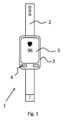
図1および図2は、脈拍計付き腕時計1として構成されている、身体に装着可能な電子機器の概略図を示している。Figures 1 and 2 show schematic diagrams of a wearable electronic device configured as a
図1に示されているように、脈拍計付き腕時計1は、アームバンド2を備えたハウジング3を含んでおり、アームバンド2によって、脈拍計付き腕時計1をユーザの腕に固定することが可能である。As shown in FIG. 1, the
ハウジング3の正面に配置されているディスプレイ5を介して、ユーザは脈拍を読み取ることができる。脈拍計付き腕時計1はさらに、例えば、ボタンの形態の操作装置4を含んでいる。ディスプレイ5は、操作のために、タッチディスプレイとして構成されていてもよい。Via a
有利には脈拍計付き腕時計1は、いわゆる「スマートウォッチ」として構成されており、したがって、多くの他の機能を提供することができる。Advantageously, the
図2は、脈拍計付き腕時計1のハウジング背面6を示している。この背面でもって、脈拍計付き腕時計のハウジング3は、装着時にユーザの皮膚に載置される。Figure 2 shows the back surface 6 of the housing of the wristwatch with
このような実施例では、金属、例えばステンレス鋼で構成された担体7が、プラスチック製のハウジング背面6にはめ込まれる。In such an embodiment, a
金属製の担体7は、ガラスで構成されているウィンドウ9a、9bが互いに間隔をあけてはめ込まれている、プラトー形状の突起8を含んでいる。The
ウィンドウ9a、9bは、ガラス圧縮封止部分として構成されている。受信ダイオード11はウィンドウ9aの下に配置され、送信ダイオード10、特にLEDはウィンドウ9bの下に配置されている。The
送信ダイオード10と受信ダイオード11とはフォトプレチスモグラフィ測定装置の一部であり、これらを介してユーザの脈拍が測定される。The transmitting
ユーザの組織内での体積体散乱によって戻ってきた、送信ダイオード10の光の強度経過が受信ダイオード11を介して測定される。The intensity profile of the light from the transmitting
脈拍とともに周期的に変動するヘモグロビン濃度に基づいて脈拍を計算することができる。担体7の突起8は、ウィンドウ9a、9bとユーザの皮膚表面との接触を改善するのに寄与する。The pulse can be calculated based on the hemoglobin concentration, which varies periodically with the pulse. The
担体7は、このような実施例において、ガラスおよび/またはガラスセラミック製のさらなるウィンドウ9dを含んでおり、このさらなるウィンドウ9dは、複数の電気的な導入端子13を含んでいる。このような実施例では、電気的な導入端子13を使用して、電子的なインターフェースのためのコンタクトが形成され、これらのコンタクトを介して、脈拍計付き腕時計1を充電することができ、さらに、特にソフトウェアをインストールするためにデータを交換することができる。The
金属製の担体7は、例えば、ハウジングの残りの部分、特にハウジング背面6と結合されていてよい。The
有利には、脈拍計付き腕時計1のハウジングは金属製である。担体7が、特に、後部のハウジング半部として設計されていてもよい。Advantageously, the housing of the
図3~図6を参照して、本発明の電子機器に使用することができる、少なくとも1つのウィンドウを備えた担体のさまざまな実施形態を説明する。With reference to Figures 3 to 6, various embodiments of carriers with at least one window that can be used in the electronic device of the present invention are described.
図3による実施例では、例えば金属、セラミックまたは非透過性のガラスを含んでいる担体7が設けられている。In the embodiment according to FIG. 3, a
ウィンドウ9aおよび9bは、送信ダイオードによって放出される光の透過率が高い材料から構成されている。
これに対して、担体7は光バリアとして機能することができ、これによって、ウィンドウ9a、9bを介した、送信ダイオードから受信ダイオードへの光の直接的な移行が阻止される。In contrast, the
光学的品質を高めるために、ウィンドウ9a、9bを研磨することが考えられる。To improve optical quality, it is possible to polish the
ウィンドウ9aおよび9bは、有利には、ガラス圧縮封止部分として構成されている。
ガラス圧縮封止部分として設計された結果、ヘリウム漏れ率が10-8mbar・l/s以下のハウジングを提供することが可能になる。 Designed as a glass compression seal, it is possible to provide a housing with a helium leak rate of less than 10−8 mbar·l/s.
本明細書に示される有利な実施形態では、少なくとも2つのウィンドウ9bが設けられており、これらの下にそれぞれ1つの送信ダイオードが配置されている。In the advantageous embodiment shown herein, at least two
有利には、送信ダイオード用のウィンドウ9bは、受信ダイオード用のウィンドウ9aの隣に、両側に配置される。Advantageously, the
このような実施例では、受信ダイオード用のウィンドウ9aは、送信ダイオード用のウィンドウ9bよりも大きく作られている。In such an embodiment, the
担体7は有利には、ウィンドウに接して、0.3mm~2mm、特に有利には0.5mm~1mmの厚さを有している。The
ウィンドウ9a、9bは、有利には、ウィンドウ9a、9bの領域において、担体7の全高を占める。The
特に担体7は、ウィンドウ9がガラス圧縮封止部分として構成されているか否かにかかわらずに、複数のコンポーネント70、71から合成されていてよい。これらのコンポーネントは、特に有利には材料結合によって相互に結合されており、例えば溶融されている。In particular, the
実施形態では、全般的に、コンポーネントのうちの1つに、ウィンドウを伴う開口部が配置されており、かつ少なくとも1つのさらなるコンポーネントが開口部27を有するコンポーネントを包囲している。図示の例では、担体7は、ウィンドウ9a、9bによって閉じられている開口部27を有しているコンポーネント71ならびにこのようなコンポーネント71を包囲しているさらなるコンポーネント70を含んでいる。すなわち、全般的に、図示の例に制限されることなく、2つのコンポーネント70、71を有する担体7が設けられており、ここで外側のコンポーネント70は、内側のコンポーネントを環状に包囲している。内側のコンポーネント71は、ここで有利には、実施形態にも図示されているように、ウィンドウ9a、9bによって閉じられている1つまたは複数の開口部27を有している。用語「環状に」とは、本開示では、決して、円環状の形態を意味しているのではない。むしろ、2つのコンポーネントの間の境界線の経過は円環状だけではなく、任意であってよく、例えば楕円形または多角形であってよい。In the embodiment, generally, an opening with a window is arranged in one of the components, and at least one further component surrounds the component with the
全般的に、複数のコンポーネントによる担体7の構築は、異なる熱膨張係数によって、合成後に、1つまたは複数のウィンドウ9に圧力を作用させるために用いられる。例えば、異なる熱膨張係数は、ガラス圧縮封止時の圧力形成をサポートするまたは補強する。したがって、この実施例に制限されることなく、実施形態では、担体7のコンポーネントのうちの少なくとも2つのコンポーネント70、71が異なる熱膨張係数を有していることが設定されている。In general, the construction of the
図3aによる実施例では、担体7は、縁部で、ガラスおよび/またはガラスセラミック製の少なくとも1つのウィンドウ9a、9bから突出している。In the embodiment according to FIG. 3a, the
これによって、ガラス圧縮封止部分として設計されたときの製造が容易になる。担体7の縁部でのこの突出と、これに伴う、残されたウィンドウ9a、9bと、によって特に、ウィンドウ9a、9bのガラス材料の体積変動を補償することが可能になる。This facilitates manufacturing when designed as a glass compression seal. This protrusion at the edge of the
有利には突出している側が担体7の内側を形成していることを理解されたい。It should be understood that the protruding side preferably forms the inside of the
図3aは、複数のコンポーネントで構成されている担体7のさらなるコンフィグレーションの例も示している。このような実施形態では、担体が多層構造を有していることが設定されており、ここで少なくとも2つのコンポーネント70、71が、担体7の層を形成している。図示の例では、担体7によって形成されるハウジングに関して、コンポーネント71は担体7の内側の層を形成し、コンポーネント72は担体7の外側の層を形成する。Figure 3a also shows an example of a further configuration of the
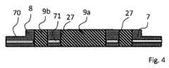
図4は、(図1および図2にも示されているように)担体7が突起8を有している代替的な実施形態を示している。ウィンドウ9a、9bは突起8の領域内にある。Figure 4 shows an alternative embodiment in which the
ウィンドウ9a、9bとユーザの皮膚との接触は、この突起によって改善される。The protrusions improve contact between the
このような例においても、図3aと類似して、例示的に、担体7の多層構造が設定されている。ここで図4は、サンドウィッチ構造を有する実施形態の例であり、ここでは、層状のコンポーネント71が、さらなるコンポーネント70内に埋設されている。In this example as well, a multi-layer structure of the
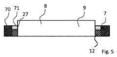
図5は、ガラスまたはガラスセラミックで構成された1つのウィンドウ9が担体7にはめ込まれており、その下に送信ダイオードと受信ダイオードとの両方が配置されている本発明の代替的な実施形態を示している。Figure 5 shows an alternative embodiment of the invention in which a
このような実施例では、ウィンドウ9は、ガラス圧縮封止部分として構成されておらず、むしろガラスを用いたはんだ付け部分12によって担体7と結合されている。In such an embodiment, the
ガラスを用いたはんだ付け部分12は、担体7の内部溝に配置されている。The
このような実施例では、ウィンドウ9自体が突起8を形成している。In such an embodiment, the
図3の例と類似して、担体7は2つのコンポーネント70、71から合成されており、ここで外側のコンポーネント70は内側のコンポーネント71を環状に包囲している。しかし、図3の例とは異なり、ここでは、内側のコンポーネント71は、環状に包囲しているコンポーネント70よりも薄い。Similar to the example of FIG. 3, the
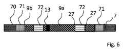
図6は、例えばピンの形態の電気的な導入端子13がウィンドウ9a内に配置されているさらなる実施例を示している。Figure 6 shows a further embodiment in which an electrical lead-in terminal 13, for example in the form of a pin, is arranged in the
その他の部分では、ウィンドウ9a、9bを備えた担体7は、図3の実施例に相応している。In other respects, the
電気的な導入端子13を介して、さらなる機能が提供されてよい。Further functionality may be provided via the electrical lead-in
例えば、電気的な導入端子13が、脈拍計付き腕時計の、付加的に存在する心電計測定装置のためのセンサ表面として用いられてよい。For example, the electrical lead-in terminal 13 may be used as a sensor surface for an additionally present electrocardiogram measuring device in a pulse meter wristwatch.
図6の例ではさらに、3つの異なるコンポーネント70、71、72を備える担体7が設けられている。In the example of Figure 6, a
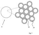
図7には、ウィンドウ9が光ファイバプレートとして構成されている、ウィンドウ9の実施例が示されている。Figure 7 shows an example of a
均質なガラス材料の代わりに、右側の詳細な図から見て取れるように、光ファイバプレートがファイバ14、特にガラスファイバで構成されており、これらは、有利には同様にガラスで構成されている被覆材15に埋め込まれている。Instead of a homogeneous glass material, as can be seen in the detailed view on the right, the fiber optic plate is made up of
被覆材15は、光伝導性のファイバ14の材料よりも低い屈折率を有している。The
したがって、境界面で全反射が生じ、光は、光伝導性のファイバ14内で一方の側から他方の側へ伝送される。Thus, total internal reflection occurs at the interface and light is transmitted from one side to the other within the optically
光ファイバプレートの使用は、このように形成されたウィンドウ9内で、それを通して光が受信ダイオードに直接的に伝送される体積体散乱が生じない、またはほとんど生じないという利点を有している。The use of a fiber optic plate has the advantage that in the
むしろ、光は個々のファイバ14内に留まる。Rather, the light remains within each
光ファイバプレートの厚さは、光学ノイズにほとんど影響を与えない。The thickness of the fiber optic plate has little effect on optical noise.
光学ノイズをさらに減らすために、特にモアレ作用を減らすために、光ファイバプレートが、着色されたファイバ、特に統計的に配分されている、着色されたファイバを含んでいてよい。To further reduce optical noise, in particular to reduce Moiré effects, the fiber optic plate may contain colored fibers, in particular statistically distributed colored fibers.
光ファイバプレートはまた、有利にはガラス圧縮封止部分として構成されている。The optical fiber plate is also advantageously configured as a glass compression seal.
図8は、担体にはめ込まれた光ファイバプレート16が使用される、さらなる実施例を示している。Figure 8 shows a further embodiment in which a
図8の断面図では、光ファイバプレート16が仕切り壁19と結合されていることが見て取れる。In the cross-sectional view of Figure 8, it can be seen that the
壁19によって、組み立てられた状態において内側に形成されたチャンバ17が形成され、この中には例えば、送信ダイオードおよび/またはフォトダイオードが配置されている。The
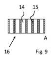
図10の平面図に示されているように、ファイバプレート16に、このように形成された透過性の領域18を中心に、少なくとも送信ダイオードの波長に対して非透過性であるマスキング20が設けられていてよい。As shown in the plan view of FIG. 10, the
図9の領域Aの詳細な図では、光ファイバプレート16が、被覆材15に埋め込まれている多数の光伝導性のファイバ14で構成されていることが見て取れる。In the detailed view of area A in FIG. 9, it can be seen that the
図11は、光ファイバプレート16が、有利には金属で構成されている担体7とどのように結合されているかを表す実施例を示している。Figure 11 shows an example of how the
このような実施例では、光ファイバプレート16は、ガラス圧縮封止部分として構成されている。すなわち、光ファイバプレート16は、担体7よりも低い線膨張係数αを有している。In this embodiment, the
製造時に、光ファイバプレート16は、少なくとも、被覆材15の軟化温度に達するように加熱される。冷却時に、担体7は光ファイバプレート16よりも収縮するため、光ファイバプレート16内に圧縮応力が発生する。During manufacture, the
図12は、光ファイバプレート16が担体7の片側に取り付けられている代替的な実施形態を示している。Figure 12 shows an alternative embodiment in which the
例えば、ガラスを用いたはんだ付けまたは陰イオン結合によって結合を行うことができる。For example, bonding can be achieved by soldering or anionic bonding with glass.
このような実施例では、仕切り壁19は担体7によって形成され、すなわち、仕切り壁19は担体と同じ高さにある。仕切り壁19を、例えば、金属製の担体7を打ち抜くことによって形成することができる。In such an embodiment, the
図13を参照して、フォトプレチスモグラフィ測定装置がどのように機能するのかを説明する。Referring to Figure 13, we explain how the photoplethysmography measurement device works.
このような実施例では、脈拍計付き腕時計は、ガラスまたはガラスセラミック製のウィンドウ9がはめ込まれている、担体7を備えたハウジング背面を含んでいる。In such an embodiment, the pulsometer watch includes a housing back with a
ハウジング内部に配置されているプリント回路基板21上に配置されている送信ダイオード10を介して、光が、ウィンドウ9を通じて、装着者の皮膚表面22に照射される。Light is projected through the
皮膚表面22を包囲している組織内で体積体散乱が発生し、皮膚表面22に入射する光の僅かな割合部分が受信ダイオード11へ後方散乱される。Volume scattering occurs within the tissue surrounding the
ヘモグロビン濃度に関連した強度の変化に基づいて、脈拍を推測することができる。The pulse rate can be estimated based on the change in intensity related to the hemoglobin concentration.
このような測定装置では、受信ダイオード11に加わる信号の大部分が光学ノイズから成る。In such a measurement device, the majority of the signal applied to the receiving
例えば、光学ノイズを減らすために、ウィンドウ9を、有利には送信ダイオード10の波長範囲の光が通過するカラーフィルタとして構成することができる。For example, to reduce optical noise, the
しかし、例えば、ガラスの不均一性のために、ウィンドウ9内でも、光学ノイズを増幅する体積体散乱が発生する可能性があることを理解されたい。これらはとりわけ、ウィンドウ9の光学的品質ならびにウィンドウ9の厚さに関連する。However, it should be understood that even within the
図14は、従来のウィンドウの代わりに光ファイバプレート16をウィンドウとして使用できることを示している。Figure 14 shows that a
光ファイバプレート16を使用する場合、光は、光ファイバに入力した後、個々の光伝導性のファイバ内に留まるので、光ファイバプレート16内の光の受信ダイオード11への後方散乱は生じないことがある、または少なくとも格段に少なくなり得る。When using a
ファイバならびにクラッドの屈折率を適切に選択することによって、許容角度を最適化することができ、これによって、光学ノイズを減らすことができる。By appropriately selecting the refractive index of the fiber and cladding, the acceptance angle can be optimized, thereby reducing optical noise.
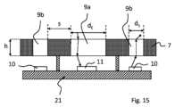
図15を参照して、ウィンドウおよび担体の幾何学的形状の影響を説明する。Referring to Figure 15, the effect of window and carrier geometry is explained.
このような実施例でも、プリント回路基板21上に配置されている送信ダイオード10ならびに受信ダイオード11を含んでいるフォトプレチスモグラフィ測定装置が示されている。In this embodiment, too, a photoplethysmography measuring device is shown that includes a transmitting
脈拍計付き腕時計の担体7には、送信ダイオード用のウィンドウ9bおよび受信ダイオード11用のウィンドウ9aがはめ込まれている。The
右に示されている送信ダイオードでは、ウィンドウ9bに入射する例示的な光ビームが記入されている。The transmitting diode shown on the right shows an exemplary light
ウィンドウ9bを通して放出された光の一部は、脈拍計付き腕時計の装着者の組織内の体積体散乱によって後方散乱され、ウィンドウ9aを通して受信ダイオード11に入射する。A portion of the light emitted through
受信ダイオード11のウィンドウ9aは直径dEを有しており、送信ダイオードのウィンドウ9bは直径dSを有している。 The
非円形の断面を有するウィンドウの場合、本発明の文脈において、直径は、別のウィンドウの方向におけるウィンドウの幅のことである(これに関しては図10における「d」を参照されたい)。For windows with a non-circular cross section, in the context of the present invention, the diameter refers to the width of the window in the direction of the other window (see in this regard "d" in Figure 10).
送信ダイオードの1つまたは複数のウィンドウ9bは、縁部で、受信ダイオードのウィンドウ9aから、距離sぶんの間隔を有している。The window or
ウィンドウは、各ウィンドウの厚さに相当する高さhを有している。The windows have a height h that corresponds to the thickness of each window.
図16は、受信ダイオードに加わる光信号のシミュレーションの等高線図である。領域が暗いほど、光信号は良好である。Figure 16 is a contour plot of a simulation of the optical signal applied to the receiving diode. The darker the area, the better the optical signal.
縦軸には、LEDまたはフォトダイオードの距離sをウィンドウの直径d(dEまたはdS)で割ったものがプロットされている。 The vertical axis plots the distance s of the LED or photodiode divided by the diameter d of the window (dE or dS ).
横軸には、LEDまたはフォトダイオードの距離sをウィンドウの厚さhで割ったものがプロットされている。The horizontal axis plots the distance s from the LED or photodiode divided by the window thickness h.
以下の条件下の際に最適な信号が得られることが判明している。
・sをdEまたはdSで割った値が3~5の間にある。
・sをhで割った値が1.5~2.5の間にある。 It has been found that the optimum signal is obtained under the following conditions:
・The value of s divided by dE or dS is between 3 and 5.
・The value of s divided by h is between 1.5 and 2.5.
図17は、本発明の脈拍計付き腕時計用のガラス圧縮封止部分のボール落下試験の写真を示している。Figure 17 shows a photograph of a ball drop test of a glass compression seal for a pulse meter wristwatch of the present invention.
4枚の写真すべてで、ウィンドウの損傷の際に、クレータ状の剥離が発生していることが見て取れる。ガラス圧縮封止部分に基づいて、材料は実質的に粉末状に破裂する。すなわち、ウィンドウから分離されるガラス材料および/またはガラスセラミック材料は粉末状である。これによって、ユーザが怪我をするリスクが低減される。同時に、ガラス圧縮封止部分によって、ウィンドウのひび割れおよび完全な破損のリスクが低減される。これは特に、ウィンドウの機械的安定性が改善されるという利点を本発明が有していることを意味し、これによって、比較的大きな負荷の際にはじめて完全に損傷が発生し、そのような損傷の場合に、ユーザが怪我をするリスクが最小限に抑えられる。In all four pictures, it can be seen that in the event of damage to the window, a crater-like spalling occurs. Due to the glass compression seal, the material essentially bursts into powder, i.e. the glass and/or glass ceramic material that separates from the window is in powder form. This reduces the risk of injury to the user. At the same time, the glass compression seal reduces the risk of the window cracking and complete breakage. This means, among other things, that the invention has the advantage that the mechanical stability of the window is improved, so that complete damage only occurs under relatively high loads, and in the event of such damage, the risk of injury to the user is minimized.
本発明は、フォトプレチスモグラフィ測定装置の光学ノイズを改善することと、脈拍計付き腕時計の安定性を高めることと、の両方を可能にした。The present invention makes it possible to both improve the optical noise of photoplethysmography measurement devices and increase the stability of wristwatches with pulse monitors.
図18は、実施形態の例を示しており、ここでは、担体7はコンポーネントとしてセラミック要素を含んでおり、これと、光ファイバプレート16の形態のウィンドウ9が結合されている。実施形態では、全般的に、有利には光ファイバプレートの形態のウィンドウが、担体70のセラミック製のコンポーネントと結合されることが設定されている。さらなるコンポーネント70は、例えば、金属製のコンポーネントであってよい。セラミック製のコンポーネントとウィンドウとの間の結合は、ガラス圧縮封止部分であり得る、または示されているように、ガラスを用いたはんだ付け部分12を介した結合であり得る。Figure 18 shows an example of an embodiment, in which the
図19は、2つのコンポーネント70、71を有している担体7の例の平面図を示しており、ここで一方のコンポーネント71には、ウィンドウ9を伴う開口部27が配置されており、少なくとも1つのさらなるコンポーネント70は、開口部27を有しているコンポーネント71を包囲している。特に、ここでは、コンポーネント70が、内側のコンポーネント71を環状に包囲している。図18の例のように、内側のコンポーネント71はセラミック製のコンポーネントであり得る。別の実施形態によれば、内側のコンポーネント71は非透過性のガラスである。外側の、環状に包囲しているコンポーネント70は、有利には金属製である。特定の例に限定されることなく、これに対して、実施形態では、2つのコンポーネント70、71を備える担体7が設けられていることが設定されており、ここで外側の金属製のコンポーネント70は、セラミックまたは非透過性のガラスで構成されている内側のコンポーネント71を環状に包囲しており、内側のコンポーネント71には、ウィンドウ9によって閉じられた開口部27が配置されている。19 shows a plan view of an example of a
本特許出願は、番号102018127619.2を有するドイツ連邦共和国特許出願の優先権を主張し、その内容は完全に、本開示の対象でもある。This patent application claims priority to the German patent application with number 102018127619.2, the contents of which are also the subject of the present disclosure in their entirety.
1 脈拍計付き腕時計
2 アームバンド
3 ハウジング
4 操作装置
5 ディスプレイ
6 ハウジング背面
7 担体
8 突起
9,9a,9b,9d ガラスまたはガラスセラミック製のウィンドウ
10 送信ダイオード
11 受信ダイオード
12 ガラスを用いたはんだ付け部分
13 電気的な導入端子
14 光伝導性のファイバ
15 被覆材
16 光ファイバプレート
17 チャンバ
18 透過性の領域
19 仕切り壁
20 マスキング
21 プリント回路基板
22 皮膚表面
27 7内の開口部
70,71,72 7のコンポーネント LIST OF
Claims (18)
Translated fromJapanese前記電子機器は、上面および下面を備えたハウジングを含んでおり、
前記ハウジング内に送信ダイオードおよび受信ダイオードが設けられており、
前記下面には、ガラスおよび/またはガラスセラミック製の少なくとも2つのウィンドウが配置されており、
第1のウィンドウの下に前記送信ダイオードが配置されており、第2のウィンドウの下に前記受信ダイオードが配置されており、
前記第1のウィンドウは、前記送信ダイオードからの出射光を透過し、前記出射光は、身体組織において後方散乱され、後方散乱された光は、前記第2のウィンドウを通り前記受信ダイオードへ向かい、
前記ハウジングは、ハウジング背面(6)および前記ハウジング背面(6)に結合された無機担体(7)を含んでおり、前記無機担体(7)には、ガラスおよび/またはガラスセラミック製の前記ウィンドウ(9,9a,9b,9d)が固定されており、かつ、前記無機担体(7)内の開口部は、前記ウィンドウ(9)によって閉じられており、ここで前記無機担体(7)は、複数のコンポーネント(70,71,72)から合成されており、
(i)前記無機担体(7)は、セラミックまたは不透明のガラスで構成されている内側のコンポーネント(71)を有し、前記内側のコンポーネント(71)に前記無機担体(7)内の開口部が配置されており、前記内側のコンポーネント(71)は、金属製のさらなるコンポーネント(70)によって包囲されており、前記ハウジングの背面(6)において、前記内側のコンポーネント(71)は、前記さらなるコンポーネント(70)および前記ウィンドウ(9)と同一平面にある、
身体に装着可能な電子機器。 An electronic device that can be worn on a body to acquire biometric information from the body,
The electronic device includes a housing having an upper surface and a lower surface;
A transmitting diode and a receiving diode are provided within the housing;
At least two windows made of glass and/or glass ceramic are arranged on the lower surface,
The transmitting diode is disposed below a first window, and the receiving diode is disposed below a second window;
the first window transmits light emitted from the transmitting diode, the emitted light is backscattered in body tissue, and the backscattered light passes through the second window toward the receiving diode;
The housing comprises a housing rear surface (6) and an inorganic carrier (7) connected to the housing rear surface (6), the window (9, 9a, 9b, 9d) made of glass and/or glass ceramic is fixed to the inorganic carrier (7) and an opening in the inorganic carrier (7) is closed by the window (9), wherein the inorganic carrier (7) is composed of a plurality of components (70, 71, 72),
(i) the inorganic carrier (7) has an inner component (71) made of ceramic or opaque glass, in which an opening in the inorganic carrier (7) is arranged, the inner component (71) being surrounded by a further component (70)made of metal ,the inner component (71) being flush with the further component (70) and with the window (9) at the rear surface (6) of the housing,
Electronic devices that can be worn on the body.
請求項1記載の、身体に装着可能な電子機器。 an inorganic support (7) is provided which comprises two components (70, 71), said further component (70) annularly surrounding said inner component (71);
2. The body-wearable electronic device according to claim 1.
請求項1または2記載の、身体に装着可能な電子機器。 an inorganic carrier (7) is provided that comprises two components (70, 71), the outer metallic component (70) annularly surrounding an inner component (71) made of ceramic or opaque glass, in which the opening (27) is arranged,
3. The body-wearable electronic device according to claim 1 or 2.
請求項1から3までのいずれか1項記載の、身体に装着可能な電子機器。 said windows (9, 9a, 9b, 9d) being fused to said inorganic support (7);
4. The body-wearable electronic device according to claim 1.
・ガラスおよび/またはガラスセラミック製の前記ウィンドウは、ガラスを用いたはんだ付けによって前記無機担体と結合されている、
請求項4記載の、身体に装着可能な電子機器。 the glass and/or glass-ceramic window is configured as a glass compression seal; or
the window made of glass and/or glass ceramic is connected to the inorganic carrier by soldering with glass;
5. The body-wearable electronic device according to claim 4.
請求項5記載の、身体に装着可能な電子機器。 the inorganic carrier (7) or at least one of the components (70, 71, 72) of the inorganic carrier (7) is configured to be non-transparent to the radiation emitted by the transmitting diode,
6. The body-wearable electronic device according to claim 5.
・前記無機担体は、材料である金属、セラミック、ガラスセラミック、不透明のガラスの1つまたは複数を含んでいる、
・前記無機担体(7)の前記コンポーネントのうちの少なくとも2つのコンポーネント(70,71)は、異なる熱膨張係数を有している、
のうちの少なくとも1つを有している、
請求項1から6までのいずれか1項記載の、身体に装着可能な電子機器。 The electronic device has the following characteristics:
The inorganic support comprises one or more of the following materials: metal, ceramic, glass-ceramic, opaque glass;
at least two of the components (70, 71) of the inorganic support (7) have different thermal expansion coefficients;
having at least one of
7. The body-wearable electronic device according to claim 1.
請求項1から7までのいずれか1項記載の、身体に装着可能な電子機器。 the inorganic carrier has a further window with at least one electrical lead-in;
8. The body-wearable electronic device according to claim 1.
請求項1から8までのいずれか1項記載の、身体に装着可能な電子機器。 the inorganic carrier has protrusions (8) in the region of the at least two windows made of glass and/or glass ceramic;
9. The body-wearable electronic device according to any one of claims 1 to 8.
請求項1から9までのいずれか1項記載の、身体に装着可能な電子機器。 the window made of glass and/or glass ceramic is configured as a fiber optic plate;
10. The body-wearable electronic device according to any one of claims 1 to 9.
請求項1から10までのいずれか1項記載の、身体に装着可能な電子機器。 the glass and/or glass ceramic window is a glass compression seal configured to generate a crater upon failure in a ball drop test;
11. The body-wearable electronic device according to any one of claims 1 to 10.
請求項1から11までのいずれか1項記載の、身体に装着可能な電子機器。 the window made of glass and/or glass ceramic is a glass compression seal configured such that upon damage in a ball drop test, the glass and/or glass ceramic material separated from the window is in powder form;
12. A body-wearable electronic device according to any one of claims 1 to 11.
・ガラスおよび/またはガラスセラミック製の前記ウィンドウは、ガラス圧縮封止部分であり、2nm以上の二乗平均平方根粗さRqを有しており、ここでガラスおよび/またはガラスセラミック製の前記ウィンドウは、前記ハウジングとは反対側の面に真っ直ぐな表面を有している、
・ガラスおよび/またはガラスセラミック製の前記ウィンドウは、ガラス圧縮封止部分であり、前記ガラス圧縮封止部分は、所定数の微小欠陥を有しており、ここでガラスおよび/またはガラスセラミック製の前記ウィンドウは、前記ハウジングとは反対側の面に真っ直ぐな表面を有している、
・ガラスおよび/またはガラスセラミック製の前記ウィンドウは、ガラス圧縮封止部分であり、前記ハウジングとは反対側の面にファイアポリッシュされた表面を有しており、そのうねりは100nm超5μm未満の値を有している、
・ガラスおよび/またはガラスセラミック製の前記ウィンドウは、前記ハウジングとは反対側の面に凹状または凸状の表面を有している、
のうちの少なくとも1つを有している、
請求項1から12までのいずれか1項記載の、身体に装着可能な電子機器。 The electronic device has the following characteristics:
the glass and/or glass ceramic window is a glass compression seal and has a root mean square roughness Rq of 2 nm or more, wherein the glass and/or glass ceramic window has a straight surface on the side opposite the housing;
the glass and/or glass ceramic window is a glass compression seal, the glass compression seal having a predetermined number of micro-defects, and the glass and/or glass ceramic window has a straight surface on the side opposite the housing;
The window made of glass and/or glass ceramic is a glass compression seal and has a fire-polished surface on the side opposite the housing, the waviness of which is greater than 100 nm and less than 5 μm;
the window made of glass and/or glass ceramic has a concave or convex surface on the side facing away from the housing;
having at least one of
13. A body-wearable electronic device according to any one of claims 1 to 12.
・ガラスおよび/またはガラスセラミック製の前記第1のウィンドウは、縁部で、ガラスおよび/またはガラスセラミック製の前記第2のウィンドウから距離sだけ離れており、前記第1のウィンドウおよび/または前記第2のウィンドウは、直径dを有しており、ここでs/d=2~7が当てはまる、
・ガラスおよび/またはガラスセラミック製の前記第1のウィンドウは、縁部で、ガラスおよび/またはガラスセラミック製の前記第2のウィンドウから距離sだけ離れており、前記第1のウィンドウおよび/または前記第2のウィンドウは、高さhを有しており、ここでs/h=1~3が当てはまる、
・ガラスおよび/またはガラスセラミック製の前記少なくとも2つのウィンドウは、前記受信ダイオードおよび/または前記送信ダイオード用のフィルタとして構成されている、
のうちの少なくとも1つを有している、
請求項1から13までのいずれか1項記載の、身体に装着可能な電子機器。 The electronic device has the following characteristics:
the first window made of glass and/or glass ceramic is separated at its edge by a distance s from the second window made of glass and/or glass ceramic, the first window and/or the second window having a diameter d, where s/d=2 to 7 applies;
the first window made of glass and/or glass ceramic is separated at its edge by a distance s from the second window made of glass and/or glass ceramic, the first window and/or the second window having a height h, where s/h=1 to 3;
the at least two windows made of glass and/or glass ceramic are configured as filters for the receiving diode and/or the transmitting diode,
having at least one of
14. A body-wearable electronic device according to any one of claims 1 to 13.
請求項8記載の、身体に装着可能な電子機器。 The electrical lead-in terminal is used as a measurement electrode or is connected to a measurement electrode.
9. The body-wearable electronic device according to claim 8.
請求項1から15までのいずれか1項記載の、身体に装着可能な電子機器。 The electronic device that can be worn on the body is a pulsimeter watch having a measuring device that functions according to the photoplethysmography measuring principle,
16. A body-wearable electronic device according to any one of claims 1 to 15.
ガラスおよび/またはガラスセラミック製の少なくとも2つのウィンドウを複数のコンポーネント(70,71,72)を備える無機担体に融合し、前記無機担体を、身体に装着可能な前記電子機器のハウジングと結合する、
身体に装着可能な電子機器の製造方法。 A method for manufacturing a wearable electronic device according to any one of claims 1 to 16, comprising the steps of:
Fusing at least two windows made of glass and/or glass ceramic to an inorganic carrier comprising a number of components (70, 71, 72) and coupling said inorganic carrier to a housing of said body-wearable electronic device;
A method for manufacturing wearable electronic devices.
Applications Claiming Priority (3)
| Application Number | Priority Date | Filing Date | Title |
|---|---|---|---|
| DE102018127619.2ADE102018127619B4 (en) | 2018-11-06 | 2018-11-06 | Wearable electronic device and process for its manufacture |
| DE102018127619.2 | 2018-11-06 | ||
| PCT/EP2019/080124WO2020094582A1 (en) | 2018-11-06 | 2019-11-04 | Electronic device which can be worn on the body, and method for producing same |
Publications (2)
| Publication Number | Publication Date |
|---|---|
| JP2022506406A JP2022506406A (en) | 2022-01-17 |
| JP7600106B2true JP7600106B2 (en) | 2024-12-16 |
Family
ID=68470509
Family Applications (2)
| Application Number | Title | Priority Date | Filing Date |
|---|---|---|---|
| JP2021523758AActiveJP7467446B2 (en) | 2018-11-06 | 2019-11-04 | Body-wearable electronic device and manufacturing method thereof |
| JP2021523766AActiveJP7600106B2 (en) | 2018-11-06 | 2019-11-04 | Body-wearable electronic device and manufacturing method thereof |
Family Applications Before (1)
| Application Number | Title | Priority Date | Filing Date |
|---|---|---|---|
| JP2021523758AActiveJP7467446B2 (en) | 2018-11-06 | 2019-11-04 | Body-wearable electronic device and manufacturing method thereof |
Country Status (6)
| Country | Link |
|---|---|
| US (3) | US20210251509A1 (en) |
| EP (2) | EP3877348A1 (en) |
| JP (2) | JP7467446B2 (en) |
| CN (3) | CN112955415B (en) |
| DE (1) | DE102018127619B4 (en) |
| WO (2) | WO2020094581A1 (en) |
Families Citing this family (6)
| Publication number | Priority date | Publication date | Assignee | Title |
|---|---|---|---|---|
| DE102018127619B4 (en) | 2018-11-06 | 2020-10-15 | Schott Ag | Wearable electronic device and process for its manufacture |
| DE102019115147C5 (en)* | 2019-06-05 | 2024-09-05 | Schott Ag | Biocompatible composite element and method for producing a biocompatible composite element |
| EP3936037A1 (en)* | 2020-07-09 | 2022-01-12 | Polar Electro Oy | Optical light guide for optical sensor |
| CN116514570B (en)* | 2022-01-24 | 2024-08-06 | 比亚迪股份有限公司 | Composite material, preparation method thereof and electronic equipment |
| CN117122276B (en)* | 2023-04-28 | 2024-10-08 | 荣耀终端有限公司 | Electronic devices |
| WO2025048273A1 (en)* | 2023-08-31 | 2025-03-06 | 삼성전자 주식회사 | Electronic device comprising light-emitting structure |
Citations (6)
| Publication number | Priority date | Publication date | Assignee | Title |
|---|---|---|---|---|
| JP2009096715A (en) | 2007-09-27 | 2009-05-07 | Nippon Electric Glass Co Ltd | Laminated glass and laminated glass member |
| WO2011016384A1 (en) | 2009-08-03 | 2011-02-10 | カシオ計算機株式会社 | Nonmagnetic stainless steel, member for radio-controlled watch, process for producing nonmagnetic stainless steel, and radio receiver |
| JP2013535639A (en) | 2010-06-30 | 2013-09-12 | コーニング インコーポレイテッド | Transparent armor with improved resistance to multiple shots by using thin cover glass |
| US20150282713A1 (en) | 2014-04-07 | 2015-10-08 | Physical Enterprises, Inc. | Systems and Methods for Optical Isolation In Measuring Physiological Parameters |
| WO2016071754A2 (en) | 2014-11-03 | 2016-05-12 | Physical Enterprises, Inc. | Systems and methods for optical isolation in measuring physiological parameters |
| US20180014781A1 (en) | 2016-07-15 | 2018-01-18 | Apple Inc. | Sensor window with integrated isolation feature |
Family Cites Families (22)
| Publication number | Priority date | Publication date | Assignee | Title |
|---|---|---|---|---|
| JPS503662A (en)* | 1973-05-14 | 1975-01-16 | ||
| JPS5140324A (en)* | 1974-10-02 | 1976-04-05 | Sumitomo Electric Industries | Koshitsutokeikeesu oyobi sonoseizoho |
| JPS5785911U (en)* | 1980-11-14 | 1982-05-27 | ||
| JPS6082658A (en)* | 1983-10-06 | 1985-05-10 | Seiko Instr & Electronics Ltd | Manufacture of case for wrist watch |
| JPH02251835A (en)* | 1989-03-25 | 1990-10-09 | Nippon Sheet Glass Co Ltd | Image input device |
| US7020508B2 (en)* | 2002-08-22 | 2006-03-28 | Bodymedia, Inc. | Apparatus for detecting human physiological and contextual information |
| JP2007083028A (en)* | 2005-08-25 | 2007-04-05 | Abbott Lab | Non-invasive testing device |
| PL2718997T3 (en)* | 2011-06-10 | 2021-02-08 | Schott Ag | Feedthrough |
| US9005129B2 (en)* | 2012-06-22 | 2015-04-14 | Fitbit, Inc. | Wearable heart rate monitor |
| KR20150061218A (en)* | 2013-11-27 | 2015-06-04 | 삼성전자주식회사 | Photo-plethysmography measurement device and measuring method using the same |
| WO2015102589A1 (en) | 2013-12-30 | 2015-07-09 | Apple Inc. | Motion artifact cancelation |
| EP3199100A1 (en)* | 2014-08-06 | 2017-08-02 | Valencell, Inc. | Earbud with a physiological information sensor module |
| US10092197B2 (en)* | 2014-08-27 | 2018-10-09 | Apple Inc. | Reflective surfaces for PPG signal detection |
| JP6476656B2 (en)* | 2014-08-27 | 2019-03-06 | セイコーエプソン株式会社 | Biological information detection device |
| KR20250021617A (en)* | 2014-09-02 | 2025-02-13 | 애플 인크. | Wearable electronic device |
| KR102299361B1 (en)* | 2014-09-03 | 2021-09-07 | 삼성전자주식회사 | Apparatus and method for monitoring blood pressure, wearable device having function of blood pressure monitoring |
| WO2016107607A1 (en)* | 2015-01-04 | 2016-07-07 | Vita-Course Technologies Co.,Ltd | System and method for health monitoring |
| US10401167B2 (en)* | 2015-09-17 | 2019-09-03 | Apple Inc. | Wearable ambient pressure gauge |
| CN105266773B (en)* | 2015-11-04 | 2018-07-27 | 上海箩箕技术有限公司 | Pulse wave sensor and wearable electronic |
| US20180184979A1 (en)* | 2017-01-04 | 2018-07-05 | The Texas A&M University System | Adhesive for optical wearable sensors |
| ES1175208Y (en) | 2017-01-05 | 2017-04-24 | Roundten Ltd | HINGE MECHANISM FOR GLASSES |
| DE102018127619B4 (en) | 2018-11-06 | 2020-10-15 | Schott Ag | Wearable electronic device and process for its manufacture |
- 2018
- 2018-11-06DEDE102018127619.2Apatent/DE102018127619B4/enactiveActive
- 2019
- 2019-11-04CNCN201980073150.6Apatent/CN112955415B/enactiveActive
- 2019-11-04JPJP2021523758Apatent/JP7467446B2/enactiveActive
- 2019-11-04CNCN202110589876.4Apatent/CN113321431B/enactiveActive
- 2019-11-04WOPCT/EP2019/080121patent/WO2020094581A1/ennot_activeCeased
- 2019-11-04EPEP19800962.3Apatent/EP3877348A1/enactivePending
- 2019-11-04JPJP2021523766Apatent/JP7600106B2/enactiveActive
- 2019-11-04WOPCT/EP2019/080124patent/WO2020094582A1/ennot_activeCeased
- 2019-11-04CNCN201980073147.4Apatent/CN112955414A/enactivePending
- 2019-11-04EPEP19798605.2Apatent/EP3877347A1/enactivePending
- 2021
- 2021-05-06USUS17/313,730patent/US20210251509A1/enactivePending
- 2021-05-06USUS17/313,690patent/US11344212B2/enactiveActive
- 2021-05-06USUS17/313,768patent/US11771333B2/enactiveActive
Patent Citations (6)
| Publication number | Priority date | Publication date | Assignee | Title |
|---|---|---|---|---|
| JP2009096715A (en) | 2007-09-27 | 2009-05-07 | Nippon Electric Glass Co Ltd | Laminated glass and laminated glass member |
| WO2011016384A1 (en) | 2009-08-03 | 2011-02-10 | カシオ計算機株式会社 | Nonmagnetic stainless steel, member for radio-controlled watch, process for producing nonmagnetic stainless steel, and radio receiver |
| JP2013535639A (en) | 2010-06-30 | 2013-09-12 | コーニング インコーポレイテッド | Transparent armor with improved resistance to multiple shots by using thin cover glass |
| US20150282713A1 (en) | 2014-04-07 | 2015-10-08 | Physical Enterprises, Inc. | Systems and Methods for Optical Isolation In Measuring Physiological Parameters |
| WO2016071754A2 (en) | 2014-11-03 | 2016-05-12 | Physical Enterprises, Inc. | Systems and methods for optical isolation in measuring physiological parameters |
| US20180014781A1 (en) | 2016-07-15 | 2018-01-18 | Apple Inc. | Sensor window with integrated isolation feature |
Also Published As
| Publication number | Publication date |
|---|---|
| JP7467446B2 (en) | 2024-04-15 |
| CN113321431A (en) | 2021-08-31 |
| CN112955415B (en) | 2022-08-12 |
| JP2022506401A (en) | 2022-01-17 |
| DE102018127619A1 (en) | 2020-05-07 |
| US20210251509A1 (en) | 2021-08-19 |
| CN112955414A (en) | 2021-06-11 |
| US20210269358A1 (en) | 2021-09-02 |
| JP2022506406A (en) | 2022-01-17 |
| DE102018127619B4 (en) | 2020-10-15 |
| WO2020094582A1 (en) | 2020-05-14 |
| CN113321431B (en) | 2023-12-26 |
| EP3877347A1 (en) | 2021-09-15 |
| US11771333B2 (en) | 2023-10-03 |
| US11344212B2 (en) | 2022-05-31 |
| EP3877348A1 (en) | 2021-09-15 |
| CN112955415A (en) | 2021-06-11 |
| WO2020094581A1 (en) | 2020-05-14 |
| US20210271208A1 (en) | 2021-09-02 |
Similar Documents
| Publication | Publication Date | Title |
|---|---|---|
| JP7600106B2 (en) | Body-wearable electronic device and manufacturing method thereof | |
| EP3946028B1 (en) | Ppg sensor having a high signal to noise ratio | |
| JP6219989B2 (en) | Multi-directional reflective optical sensor module, multi-directional reflective optical sensor accessory, and multi-directional reflective optical sensor device | |
| US8929966B2 (en) | Physiological monitoring methods | |
| US10299724B2 (en) | Wristwatch including an integrated pulse oximeter or other modules that sense physiological data | |
| WO2014045774A1 (en) | Biosensor and method for manufacturing biosensor | |
| CN105358051B (en) | Light detection unit and living body information detection device | |
| KR102348195B1 (en) | Optical Analyte Monitering System and Method | |
| KR20150071304A (en) | Apparatus for measuring bio-information | |
| JP7245774B2 (en) | Devices and methods for physiological parameter sensing | |
| CN116058790B (en) | Testing and measuring devices | |
| CN112006666B (en) | Biological information measuring device | |
| RU2839510C1 (en) | Optical sensor of short-wave infrared spectrum for biomedical applications | |
| CN116234218A (en) | One-piece cover, electronic device, and method for making one-piece cover |
Legal Events
| Date | Code | Title | Description |
|---|---|---|---|
| A621 | Written request for application examination | Free format text:JAPANESE INTERMEDIATE CODE: A621 Effective date:20220727 | |
| A977 | Report on retrieval | Free format text:JAPANESE INTERMEDIATE CODE: A971007 Effective date:20230331 | |
| A131 | Notification of reasons for refusal | Free format text:JAPANESE INTERMEDIATE CODE: A131 Effective date:20230404 | |
| A601 | Written request for extension of time | Free format text:JAPANESE INTERMEDIATE CODE: A601 Effective date:20230630 | |
| A521 | Request for written amendment filed | Free format text:JAPANESE INTERMEDIATE CODE: A523 Effective date:20230810 | |
| A131 | Notification of reasons for refusal | Free format text:JAPANESE INTERMEDIATE CODE: A131 Effective date:20230925 | |
| A601 | Written request for extension of time | Free format text:JAPANESE INTERMEDIATE CODE: A601 Effective date:20231219 | |
| A521 | Request for written amendment filed | Free format text:JAPANESE INTERMEDIATE CODE: A523 Effective date:20240105 | |
| A02 | Decision of refusal | Free format text:JAPANESE INTERMEDIATE CODE: A02 Effective date:20240402 | |
| A521 | Request for written amendment filed | Free format text:JAPANESE INTERMEDIATE CODE: A523 Effective date:20240731 | |
| A911 | Transfer to examiner for re-examination before appeal (zenchi) | Free format text:JAPANESE INTERMEDIATE CODE: A911 Effective date:20240806 | |
| TRDD | Decision of grant or rejection written | ||
| A01 | Written decision to grant a patent or to grant a registration (utility model) | Free format text:JAPANESE INTERMEDIATE CODE: A01 Effective date:20241119 | |
| A61 | First payment of annual fees (during grant procedure) | Free format text:JAPANESE INTERMEDIATE CODE: A61 Effective date:20241204 | |
| R150 | Certificate of patent or registration of utility model | Ref document number:7600106 Country of ref document:JP Free format text:JAPANESE INTERMEDIATE CODE: R150 |