JP7598978B2 - Systems, methods and computing devices for vehicle navigation - Patents.com - Google Patents
Systems, methods and computing devices for vehicle navigation - Patents.comDownload PDFInfo
- Publication number
- JP7598978B2 JP7598978B2JP2023117218AJP2023117218AJP7598978B2JP 7598978 B2JP7598978 B2JP 7598978B2JP 2023117218 AJP2023117218 AJP 2023117218AJP 2023117218 AJP2023117218 AJP 2023117218AJP 7598978 B2JP7598978 B2JP 7598978B2
- Authority
- JP
- Japan
- Prior art keywords
- vehicle
- computing device
- data
- road segment
- vec
- Prior art date
- Legal status (The legal status is an assumption and is not a legal conclusion. Google has not performed a legal analysis and makes no representation as to the accuracy of the status listed.)
- Active
Links
Images


Classifications
- G—PHYSICS
- G01—MEASURING; TESTING
- G01C—MEASURING DISTANCES, LEVELS OR BEARINGS; SURVEYING; NAVIGATION; GYROSCOPIC INSTRUMENTS; PHOTOGRAMMETRY OR VIDEOGRAMMETRY
- G01C21/00—Navigation; Navigational instruments not provided for in groups G01C1/00 - G01C19/00
- G01C21/26—Navigation; Navigational instruments not provided for in groups G01C1/00 - G01C19/00 specially adapted for navigation in a road network
- G01C21/34—Route searching; Route guidance
- G01C21/3407—Route searching; Route guidance specially adapted for specific applications
- G01C21/3415—Dynamic re-routing, e.g. recalculating the route when the user deviates from calculated route or after detecting real-time traffic data or accidents
- B—PERFORMING OPERATIONS; TRANSPORTING
- B60—VEHICLES IN GENERAL
- B60W—CONJOINT CONTROL OF VEHICLE SUB-UNITS OF DIFFERENT TYPE OR DIFFERENT FUNCTION; CONTROL SYSTEMS SPECIALLY ADAPTED FOR HYBRID VEHICLES; ROAD VEHICLE DRIVE CONTROL SYSTEMS FOR PURPOSES NOT RELATED TO THE CONTROL OF A PARTICULAR SUB-UNIT
- B60W60/00—Drive control systems specially adapted for autonomous road vehicles
- B60W60/001—Planning or execution of driving tasks
- B60W60/0011—Planning or execution of driving tasks involving control alternatives for a single driving scenario, e.g. planning several paths to avoid obstacles
- B—PERFORMING OPERATIONS; TRANSPORTING
- B60—VEHICLES IN GENERAL
- B60W—CONJOINT CONTROL OF VEHICLE SUB-UNITS OF DIFFERENT TYPE OR DIFFERENT FUNCTION; CONTROL SYSTEMS SPECIALLY ADAPTED FOR HYBRID VEHICLES; ROAD VEHICLE DRIVE CONTROL SYSTEMS FOR PURPOSES NOT RELATED TO THE CONTROL OF A PARTICULAR SUB-UNIT
- B60W60/00—Drive control systems specially adapted for autonomous road vehicles
- B60W60/001—Planning or execution of driving tasks
- B60W60/0027—Planning or execution of driving tasks using trajectory prediction for other traffic participants
- B—PERFORMING OPERATIONS; TRANSPORTING
- B60—VEHICLES IN GENERAL
- B60W—CONJOINT CONTROL OF VEHICLE SUB-UNITS OF DIFFERENT TYPE OR DIFFERENT FUNCTION; CONTROL SYSTEMS SPECIALLY ADAPTED FOR HYBRID VEHICLES; ROAD VEHICLE DRIVE CONTROL SYSTEMS FOR PURPOSES NOT RELATED TO THE CONTROL OF A PARTICULAR SUB-UNIT
- B60W30/00—Purposes of road vehicle drive control systems not related to the control of a particular sub-unit, e.g. of systems using conjoint control of vehicle sub-units
- B60W30/18—Propelling the vehicle
- B60W30/18009—Propelling the vehicle related to particular drive situations
- B60W30/18159—Traversing an intersection
- G—PHYSICS
- G01—MEASURING; TESTING
- G01C—MEASURING DISTANCES, LEVELS OR BEARINGS; SURVEYING; NAVIGATION; GYROSCOPIC INSTRUMENTS; PHOTOGRAMMETRY OR VIDEOGRAMMETRY
- G01C21/00—Navigation; Navigational instruments not provided for in groups G01C1/00 - G01C19/00
- G01C21/26—Navigation; Navigational instruments not provided for in groups G01C1/00 - G01C19/00 specially adapted for navigation in a road network
- G01C21/34—Route searching; Route guidance
- G01C21/3446—Details of route searching algorithms, e.g. Dijkstra, A*, arc-flags or using precalculated routes
- B—PERFORMING OPERATIONS; TRANSPORTING
- B60—VEHICLES IN GENERAL
- B60W—CONJOINT CONTROL OF VEHICLE SUB-UNITS OF DIFFERENT TYPE OR DIFFERENT FUNCTION; CONTROL SYSTEMS SPECIALLY ADAPTED FOR HYBRID VEHICLES; ROAD VEHICLE DRIVE CONTROL SYSTEMS FOR PURPOSES NOT RELATED TO THE CONTROL OF A PARTICULAR SUB-UNIT
- B60W2556/00—Input parameters relating to data
- B60W2556/40—High definition maps
- B—PERFORMING OPERATIONS; TRANSPORTING
- B60—VEHICLES IN GENERAL
- B60W—CONJOINT CONTROL OF VEHICLE SUB-UNITS OF DIFFERENT TYPE OR DIFFERENT FUNCTION; CONTROL SYSTEMS SPECIALLY ADAPTED FOR HYBRID VEHICLES; ROAD VEHICLE DRIVE CONTROL SYSTEMS FOR PURPOSES NOT RELATED TO THE CONTROL OF A PARTICULAR SUB-UNIT
- B60W2556/00—Input parameters relating to data
- B60W2556/45—External transmission of data to or from the vehicle
- B60W2556/65—Data transmitted between vehicles
Landscapes
- Engineering & Computer Science (AREA)
- Radar, Positioning & Navigation (AREA)
- Remote Sensing (AREA)
- Automation & Control Theory (AREA)
- Transportation (AREA)
- Mechanical Engineering (AREA)
- Physics & Mathematics (AREA)
- General Physics & Mathematics (AREA)
- Human Computer Interaction (AREA)
- Traffic Control Systems (AREA)
- Navigation (AREA)
Description
Translated fromJapanese本発明は、車両のナビゲーションに関する。The present invention relates to vehicle navigation.
先進運転支援システム(ADAS)及び自律走行(AD)システムは、安全性の向上、ナビゲーションの自動化、利便性の向上、効率性の向上のために、車両制御を自動化またはその他の方法で強化する。従来、部分的にしか自動化されていない車両には、コストを抑え、市場に受け入れられやすいように、限られた数のセンサとプロセッサが搭載されている。自動運転のレベルを半自動運転や完全自動運転まで高めるには、車両に異なるタイプのセンサを搭載し、車両の周囲を継続的に監視することが必要である。さらに、これらの半自動または完全自動車両は通常、障害物の認識やその他のナビゲーション機能の実行など、すべてのセンサデータをリアルタイムで処理することが必要である。しかし、異なるタイプのセンサからの大量のセンサデータをリアルタイムで処理するためには、処理の大きなキャパシティが必要となり、車両のコストが大幅に上昇し得る。Advanced driver assistance systems (ADAS) and autonomous driving (AD) systems automate or otherwise enhance vehicle control to improve safety, automate navigation, increase convenience, and improve efficiency. Traditionally, partially automated vehicles are equipped with a limited number of sensors and processors to keep costs down and facilitate market acceptance. Increasing the level of automation to semi-autonomous or fully autonomous driving requires that the vehicle be equipped with different types of sensors and continuously monitor the vehicle's surroundings. Furthermore, these semi-autonomous or fully autonomous vehicles are typically required to process all sensor data in real time, such as to recognize obstacles and perform other navigation functions. However, processing large amounts of sensor data from different types of sensors in real time requires large processing capacity, which can significantly increase the cost of the vehicle.
本発明の一態様のシステムは、1以上のプロセッサと、前記1以上のプロセッサによって実行可能な命令を格納する、1以上の計算機読み取り可能な記憶媒体と、を含み、前記1以上のプロセッサが実行する処理は、車両の出発地位置と目的地位置との間の複数の候補ルートを決定し、前記複数の候補ルートの各候補ルートを複数の道路セグメントにセグメント化し、前記車両に搭載された車両センサの車両センサ構成情報を受信し、前記車両に搭載された車両センサの視野、または前記車両に搭載された計算リソースの少なくとも一方が、前記複数の候補ルートの第1の候補ルートの道路セグメントの自律ナビゲーションに関連する閾値を満たさないと判定し、前記車両が前記第1の候補ルートの道路セグメントを自律的にナビゲートすることに関連する前記閾値を満たすことを可能にするために、前記車両の外部の計算装置が、前記車両のために少なくとも1つの計算タスクを実行することをスケジュールされることの決定に基づいて、前記車両のために、前記第1の候補ルートを選択する。A system according to one aspect of the present invention includes one or more processors and one or more computer-readable storage media storing instructions executable by the one or more processors, and the process executed by the one or more processors includes determining a plurality of candidate routes between a start position and a destination position of a vehicle, segmenting each of the plurality of candidate routes into a plurality of road segments, receiving vehicle sensor configuration information for vehicle sensors mounted on the vehicle, determining that at least one of the field of view of the vehicle sensors mounted on the vehicle or the computational resources mounted on the vehicle does not satisfy a threshold associated with autonomous navigation of a road segment of a first candidate route of the plurality of candidate routes, and selecting the first candidate route for the vehicle based on a determination that a computing device external to the vehicle is scheduled to perform at least one computing task for the vehicle to enable the vehicle to satisfy the threshold associated with autonomously navigating the road segment of the first candidate route.
本発明の一態様の方法は、車両に搭載された1以上のプロセッサが、ネットワークを介してサービス計算装置に、前記車両に搭載されたセンサに関連するセンサ情報を含む車両情報と、目的地位置とを送信し、前記1以上のプロセッサが、前記サービス計算装置から、前記目的地位置まで前記車両を自律的に走行させるための複数の道路セグメントを含むルートを示すルーティング情報を受信し、前記1以上のプロセッサが、前記ルートに沿って前記車両をナビゲートし、前記1以上のプロセッサが、前記ルートの前記複数の道路セグメント内の道路セグメントに関連付けられたサービス計算装置から、前記道路セグメントの処理結果を受信し、前記1以上のプロセッサが、前記受信した処理結果を、前記道路セグメントの自律ナビゲーションの間に、前記車両に搭載されたセンサから前記1以上のプロセッサによって決定された認識データと組み合わせて使用する、ことを含む。A method according to one aspect of the invention includes one or more processors on a vehicle transmitting vehicle information, including sensor information associated with sensors on the vehicle, and a destination location to a service computing device over a network; the one or more processors receiving routing information from the service computing device indicating a route including a plurality of road segments for autonomously navigating the vehicle to the destination location; the one or more processors navigating the vehicle along the route; the one or more processors receiving processing results for the road segments from a service computing device associated with a road segment within the plurality of road segments of the route; and the one or more processors using the received processing results in combination with perception data determined by the one or more processors from sensors on the vehicle during autonomous navigation of the road segments.
本発明の一態様の計算装置は、実行可能な命令によって処理を実行するように構成された1以上のプロセッサを含み、前記処理は、サービス計算装置から、前記計算装置が関連付けられている道路セグメントを第1の車両が通過すると予測される第1の時刻を含む、前記第1の車両に関連する第1の車両情報を受信し、前記第1の車両が、前記道路セグメントの自律ナビゲーションに関連付けられた第1の閾値レベルを満たさないセンシングリソースまたは計算リソースの少なくとも一方を有すると判定することに基づいて、前記第1の時刻における前記計算装置の計算負荷が第2の閾値より小さいと判定し、前記サービス計算装置に、前記計算装置が前記第1の車両が前記道路セグメントを自律的にナビゲートすることを支援するための少なくとも1つの計算タスクを実行することをスケジュールされている、という指示を送信し、前記第1の車両が前記道路セグメントに到達したことを検出することに基づいて、前記第1の車両に前記計算タスクの結果を提供する。A computing device according to one aspect of the present invention includes one or more processors configured to execute a process according to executable instructions, the process including receiving from a service computing device first vehicle information associated with the first vehicle, the first vehicle information including a first time when the first vehicle is predicted to traverse a road segment with which the computing device is associated, determining that the computing device has at least one of sensing or computing resources that does not meet a first threshold level associated with autonomous navigation of the road segment, determining that the computing device has a computational load at the first time that is less than a second threshold, transmitting an indication to the service computing device that the computing device is scheduled to perform at least one computational task to assist the first vehicle in autonomously navigating the road segment, and providing the first vehicle with results of the computational task based on detecting that the first vehicle has reached the road segment.
以下において、図を参照して詳細な説明を行う。図において、参照番号の左端の桁は、参照番号が最初に現れる図を識別する。異なる図において同じ参照番号を使用することは、類似または同一の項目または特徴を示す。The detailed description below refers to the figures. In the figures, the leftmost digit(s) of a reference number identifies the figure in which the reference number first appears. Use of the same reference number in different figures indicates similar or identical items or features.
本明細書の実施形態は、自律走行(AD)車両またはADAS車両などの車両のリソースを割り当てるための技術及び配置に向けられている。本明細書のいくつかの実施形態は、車両が通過すると予想されるルートに沿って、車両が利用可能な計算リソースを特定する。利用可能な計算リソースの決定は、車両に搭載されて利用可能と予想される計算リソースを含んでもよく、ルートを通過する間に車両によって利用され得る車両の外部の他の計算リソースも含んでもよい。さらに、本明細書の実施形態は、車両が自律走行を実行できる時間を最大化するために、車両がルートに沿って予想される場所に到達する前に、車両の計算タスクを効果的に割り当てることができる。これは、人間によって操作される、または、センサデータ処理が不十分な状態で自律的に操作されることとは対照的に、車両が安全に自律的に操作される時間を増やすことによって、車両の安全性を高めるのに役立つ。Embodiments herein are directed to techniques and arrangements for allocating resources for a vehicle, such as an autonomous driving (AD) vehicle or an ADAS vehicle. Some embodiments herein identify computational resources available to a vehicle along a route that the vehicle is expected to traverse. The determination of available computational resources may include computational resources expected to be available on board the vehicle, and may also include other computational resources external to the vehicle that may be utilized by the vehicle while traversing the route. Additionally, embodiments herein may effectively allocate computational tasks for the vehicle before the vehicle reaches an expected location along the route to maximize the time the vehicle can perform autonomous navigation. This helps to increase vehicle safety by increasing the amount of time the vehicle is safely operated autonomously, as opposed to being operated by a human or operating autonomously with insufficient sensor data processing.
本明細書の実施形態は、車両の最適ルートを決定するために使用され得る予防観測ゾーン(POZ:Precautionary Observation Zone)の計算を含み得る。POZの決定は、最適ルートを選択する際に車両に採用される車載センサのタイプ及び能力を考慮することができ、さらに、各候補ルート上の道路の特徴、各候補ルートをナビゲートするために必要な視野(FOV)、及び後述するような他の事項を考慮することができる。Embodiments herein may include the calculation of a Precautionary Observation Zone (POZ) that may be used to determine an optimal route for a vehicle. The determination of the POZ may take into account the type and capabilities of on-board sensors employed by the vehicle in selecting the optimal route, and may further take into account the characteristics of the roads along each candidate route, the field of view (FOV) required to navigate each candidate route, and other considerations as described below.
いくつかのケースにおいて、ルートに沿った各場所における予想される計算タスクは、車両が通過すると予想されるルートに沿ったPOZを決定することに少なくとも部分的に基づいて決定され得る。例えば、ルートに沿った特定のゾーンが、より大量のセンサリソース及び/または計算リソース(例えば、車両に搭載されて利用可能なリソースよりも多くのリソース)を必要とする場合、本実施形態におけるシステムは、ルートに沿った任意のタスクオフロード領域を事前に特定してもよく、予想されるセンシングタスク及び/または認識タスクのうちの1以上を、ルートに沿って配置され得る利用可能な計算リソースに効果的に割り当ててもよい。したがって、実施形態は、選択されたルートに沿った計算負荷の高いゾーンを事前に決定し、これらのゾーンを、車両にとってセンシングタスクオフロード、計算タスクオフロード、及び/または計算タスク共有が望ましい場所として指定することができる。In some cases, the expected computational tasks at each location along the route may be determined based at least in part on determining the POZs along the route that the vehicle is expected to traverse. For example, if a particular zone along the route requires a greater amount of sensor and/or computational resources (e.g., more resources than are available on board the vehicle), the system in this embodiment may pre-identify any task offload areas along the route and effectively assign one or more of the expected sensing and/or recognition tasks to available computational resources that may be located along the route. Thus, embodiments may pre-determine computationally intensive zones along a selected route and designate these zones as locations where sensing task offloading, computation task offloading, and/or computation task sharing are desirable for the vehicle.
実施形態では、システムは、ルートの近くに位置し、1または複数の路側ユニットを介して近くの車両と通信することができる1または複数の車両エッジ計算装置(VEC)に、センシング及び計算タスクをオフロードすることができる。例えば、データセンタまたは他のクラウドインフラストラクチャにある計算装置との通信とは対照的に、本明細書におけるVECは、クラウドベースのサーバの比較的遠隔の位置と比較して、路側により近い位置に処理ユニットがあるため、タイムクリティカルな計算タスクを実行するのに適した位置にある。例えば、VECは、車両と車外の計算装置との間のデータ通信のネットワーク待ち時間を回避または実質的に短縮することができる。さらに、VECの近くにある利用可能なセンシング及び計算リソースを有する他の車両は、センシング及び/または計算リソースをVECに提供し、データを処理及び/またはデータを車両に対して提供することもできる。In an embodiment, the system can offload sensing and computation tasks to one or more vehicle edge computing devices (VECs) located near the route and capable of communicating with nearby vehicles via one or more roadside units. For example, in contrast to communicating with computing devices in a data center or other cloud infrastructure, the VECs herein are well-positioned to perform time-critical computation tasks because their processing units are located closer to the roadside compared to the relatively remote location of a cloud-based server. For example, the VECs can avoid or substantially reduce network latency for data communications between the vehicle and off-vehicle computing devices. Additionally, other vehicles with available sensing and computation resources near the VEC can provide sensing and/or computation resources to the VEC to process data and/or provide data to the vehicle.
本明細書の実施形態は、VEC、過剰な計算キャパシティを有する他の車両、及びより遠隔に位置するクラウドベースのサービス計算装置の組み合わせを提供し、これらの装置は、個別に及び/または一緒に、追加の計算リソースを必要とするそれぞれの車両にセンシング及び計算リソースを提供することができ、一方で、それぞれの車両は、自身の電子制御ユニット(ECU)及び自身の搭載センサを使用してオンボード処理も実行する。従って、本明細書の実施形態は、特定のルートに沿ったすべての場所において、所望レベルの自動運転のために不十分なセンシング及び/または計算リソースを有する可能性のある車両の問題を解決することができる。例えば、本明細書の実施形態は、車両によって通過される1または複数の道路セグメントのPOZを完全に感知することができない車両のために、近くのVECがセンシング及び/または計算タスクのサポートを提供することを要求する場所を事前に決定することができる。例えば、遠隔に位置するサービス計算装置は、VEC上の利用可能な計算リソースに従って、計算タスクを近くのVECに割り当てることができる。本明細書の実施形態は、さらに、自律走行を実現するためにより高いレベルの計算リソースを必要とする可能性がある場所であるPOZとして、ルートに沿った特定の領域を事前に特定してもよい。システムは、VEC及び/またはクラウドベースのサービス計算装置の利用可能な計算リソースをスケジューリングすることによって、オフロードされた計算タスクを適宜割り当てて実行するためのスケジューリングを実行してもよい。Embodiments herein provide a combination of VECs, other vehicles with excess computing capacity, and more remotely located cloud-based service computing devices that can individually and/or together provide sensing and computing resources to each vehicle that needs additional computing resources, while each vehicle also performs on-board processing using its own electronic control unit (ECU) and its own on-board sensors. Thus, embodiments herein can solve the problem of vehicles that may have insufficient sensing and/or computing resources for a desired level of autonomous driving at all locations along a particular route. For example, embodiments herein can predetermine locations where a nearby VEC will request to provide sensing and/or computing task support for a vehicle that cannot fully sense the POZ of one or more road segments traversed by the vehicle. For example, a remotely located service computing device can assign computing tasks to nearby VECs according to available computing resources on the VECs. Embodiments herein may further predetermine certain areas along a route as POZs, locations that may require a higher level of computing resources to achieve autonomous driving. The system may perform scheduling to appropriately allocate and execute offloaded computing tasks by scheduling available computing resources of the VEC and/or cloud-based service computing devices.
上述のように、安全運転は個人にとってだけでなく、あらゆる種類の輸送やサービス事業にとっても重要である。安全性は、自動運転システムの幅広い開発と急速な進歩の根本的な理由ある。完全または部分的に自動化された車両には複数のセンサが搭載され、車両周辺を継続的に監視して障害物を認識し、安全性を向上させる。先行研究によれば、交通事故のほとんどは人間の運転ミスによるものである。従って、高度なセンシングとデータ処理装置を備えた最先端の自動運転車両は、改良されたアルゴリズムを使用することで、車両衝突の発生率を大幅に低減できる。As mentioned above, safe driving is important not only for individuals but also for all kinds of transportation and service businesses. Safety is the underlying reason for the widespread development and rapid progress of autonomous driving systems. Fully or partially automated vehicles are equipped with multiple sensors to continuously monitor the vehicle's surroundings and recognize obstacles, thus improving safety. Previous studies have shown that most traffic accidents are caused by human driving errors. Therefore, cutting-edge autonomous vehicles equipped with advanced sensing and data processing devices can significantly reduce the incidence of vehicle collisions by using improved algorithms.
本明細書における自動車両のセンサは、最終的に衝突を回避するのに役立つように、車両の周囲の障害物や道路の特徴を検出する上で主要な役割を果たす。本明細書の処理装置は、最先端のアルゴリズムを利用してリアルタイムでセンサデータを処理し、必要な制御信号を様々なシステム及び/またはアクチュエータに送信して車両を制御することができる。車両の周囲に複数の冗長な高分解能センサを配置し、処理キャパシティの高い複数の処理ユニットを併用することで、車両はあらゆる条件下で自律的に動作できる。しかし、このような構成は、車両のコストを大幅に増加させるだけでなく、車両の効率を低下させる可能性がある。したがって、これらの問題に対処するために、本明細書の実施形態では、より限られた数のセンサと、最適化された処理キャパシティを有する処理ユニットとを使用することができる。限られた数のセンサを使用することは、多くの自動運転シナリオには十分であるが、いくつかのケースでは、限られた数のセンサでは、特定の道路セグメント、交差点などを安全にナビゲートするために必要なすべての領域を感知するのに十分でない場合がある。その結果、本明細書の実施形態では、インフラストラクチャ・センサ、他の車両センサ、または近傍で利用可能な車両外部の他のセンサから得られるセンシング情報を使用するなどして、これらの場所における車両のセンシング能力を補強するためにVECを採用することができる。いくつかのケースにおいて、VECは車両に代わって外部のセンサデータを処理し、センシング結果を車両に提供して車両の自律走行を支援する。Sensors of an automated vehicle herein play a key role in detecting obstacles and road features around the vehicle to ultimately help avoid collisions. A processing device herein can utilize state-of-the-art algorithms to process sensor data in real time and send necessary control signals to various systems and/or actuators to control the vehicle. By placing multiple redundant high-resolution sensors around the vehicle, in conjunction with multiple processing units with high processing capacity, the vehicle can operate autonomously under all conditions. However, such a configuration can significantly increase the cost of the vehicle as well as reduce the efficiency of the vehicle. Therefore, to address these issues, embodiments herein can use a more limited number of sensors and a processing unit with optimized processing capacity. While using a limited number of sensors is sufficient for many automated driving scenarios, in some cases, the limited number of sensors may not be sufficient to sense all areas required to safely navigate a particular road segment, intersection, etc. As a result, embodiments herein can employ a VEC to augment the vehicle's sensing capabilities in these locations, such as by using sensing information from infrastructure sensors, other vehicle sensors, or other sensors external to the vehicle that are available in the vicinity. In some cases, the VEC processes external sensor data on behalf of the vehicle and provides the sensing results to the vehicle to assist in the vehicle's autonomous driving.
車両の安全性を確保するために、本明細書の実施形態は、自動運転時間を最大化しようとする場合がある。しかしながら、状況によっては、限られた数のセンサを備えた車両では、いくつかのタイプの道路カテゴリや道路形状を考慮した場合、ルート全体にわたって連続的な自動運転を保証することができない。例えば、フロントカメラとレーダを搭載した車両は、一般的に高速道路での自律走行を確保できるが、このセンサの組み合わせは、市街地での自動運転には不十分である。そのため、本明細書の実施形態は、接続データとしてインフラストラクチャ及び/または他の車両センサの利用を自動運転のために採用する。しかし、これらの追加のデータを処理するためには、追加の計算リソースも必要となる。接続性とクラウド計算の最近の進歩により、VECと中央クラウドベースの計算技術は、車両に追加情報を提供するために、利用され得る。しかしながら、遠隔クラウドベースの計算リソース(例えば、本明細書におけるサービス計算装置)は、一般に、車両から地理的に離れたデータセンタに配置されるため、サービス計算装置と車両との間の通信に著しい遅延が生じ、時間的に重要なアプリケーションを、車両の安全を確保するのに十分な短時間で実行し、車両に戻すことができない場合がある。To ensure vehicle safety, embodiments herein may attempt to maximize autonomous driving time. However, in some circumstances, a vehicle with a limited number of sensors cannot guarantee continuous autonomous driving throughout the entire route when considering some types of road categories and road shapes. For example, a vehicle equipped with a front camera and radar can generally ensure autonomous driving on highways, but this sensor combination is insufficient for autonomous driving in urban areas. Therefore, embodiments herein employ the use of infrastructure and/or other vehicle sensors as connectivity data for autonomous driving. However, additional computational resources are also required to process these additional data. With recent advances in connectivity and cloud computing, VEC and central cloud-based computing techniques may be utilized to provide additional information to the vehicle. However, because remote cloud-based computing resources (e.g., the service computing device herein) are generally located in a data center that is geographically distant from the vehicle, significant delays may occur in communication between the service computing device and the vehicle, and time-critical applications may not be able to be executed and returned to the vehicle in a short enough time to ensure the safety of the vehicle.
本明細書の例では、移動の開始時に、車両は、その現在位置、目的地、センサの種類及び構成、ならびに処理ユニットの仕様をサービス計算装置と共有することができる。サービス計算装置は、目的地までの候補ルートを特定し、候補ルートのPOZを計算する。POZは、車両の安全を確保するために車両が監視すべき領域であってよい。POZは、ルート中の全ての道路セグメント/ウェイポイントについて決定されてよい。POZは、以下で追加的に説明するように、例えば、道路のタイプ、ウェイポイントの位置などに応じて変化する3D領域であってもよい。In the examples herein, at the start of a trip, the vehicle may share its current location, destination, sensor types and configurations, and processing unit specifications with the service computing device. The service computing device identifies potential routes to the destination and calculates the POZs for the potential routes. The POZs may be areas that the vehicle should monitor to ensure vehicle safety. The POZs may be determined for all road segments/waypoints in the route. The POZs may be 3D areas that change depending on, for example, road type, location of waypoints, etc., as additionally described below.
サービス計算装置は、すべての候補道路セグメントに沿って特定された POZ と比較して、車両センサ構成及び処理ユニット仕様を分析し、自動運転の時間量を最大化するための最適ルートを選択する。サービス計算装置は、車両センサ構成及び車両処理ユニット仕様に基づいて、自動運転のための道路特徴や障害物の特定など、車両がセンサデータを分析するために追加の計算リソースを必要とするルート上の道路セグメントを特定してよい。サービス計算装置は、特定された場所のVECと車両情報を共有し、車両がそれぞれのVECに最も近い道路セグメントに接近すると予想される時間を共有する。サービス計算装置から車両情報を受信すると、それぞれのVECは、その時間セグメントのスケジュールされた計算タスクを分析し、それぞれのVECの計算リソースの利用可能性に基づいて、特定の車両を支援する要求を確認または拒否することができる。さらに、それぞれのVECからのフィードバックに基づいて、サービス計算装置は、ルーティング情報を更新してもよく、ルーティング情報を車両に送信してもよい。例えば、VECが特定の車両の要求をサポートできない場合、サービス計算装置は、代替候補ルートが車両のために利用可能であるか否かを決定することができる。車両搭載処理装置、VECキャパシティ利用可能性、及びサービス計算装置利用可能性を考慮しながら、事前に実行される計算タスク分配及びオフロードのために説明される技術は、自律または半自律車両の自動運転の時間を最大化し、その安全性を確保するための大きな利点を提供する。The service computation device analyzes the vehicle sensor configuration and processing unit specifications compared to the identified POZs along all candidate road segments and selects an optimal route to maximize the amount of time for autonomous driving. Based on the vehicle sensor configuration and vehicle processing unit specifications, the service computation device may identify road segments on the route where the vehicle requires additional computational resources to analyze sensor data, such as identifying road features and obstacles for autonomous driving. The service computation device shares vehicle information with VECs at the identified locations and the time when the vehicle is expected to approach the road segment closest to the respective VEC. Upon receiving vehicle information from the service computation device, each VEC may analyze the scheduled computational tasks for that time segment and confirm or deny a request to assist the particular vehicle based on the availability of computational resources of the respective VEC. Furthermore, based on feedback from the respective VEC, the service computation device may update routing information or send routing information to the vehicle. For example, if a VEC cannot support a particular vehicle's request, the service computation device may determine whether an alternative candidate route is available for the vehicle. The described techniques for proactive computational task distribution and offloading, taking into account vehicle on-board processing units, VEC capacity availability, and service computational device availability, provide significant advantages for maximizing the time of autonomous operation and ensuring the safety of autonomous or semi-autonomous vehicles.
例えば、車両は、サービス計算装置によって提供される接続されたデータ分析プラットフォームにアクセスし、車両上で利用可能な車載センサに関する情報をサービス計算装置上のデータ分析プラットフォームに提供するとともに、出発地位置、目的地位置、車両構成情報などを提供することができる。さらに、車両は、データ分析プラットフォームから、目的地位置に到達するためにデータ分析プラットフォームによって選択された1または複数の最適ルートに関する情報を受信してもよい。他の例では、ルート決定は、車両に搭載された計算装置、または車両のルートに沿って車両に近接して配置されたVECなどによって実行されてもよい。For example, the vehicle may access a connected data analytics platform provided by the service computing device and provide information about on-board sensors available on the vehicle to the data analytics platform on the service computing device, as well as provide a start location, a destination location, vehicle configuration information, etc. Additionally, the vehicle may receive information from the data analytics platform regarding one or more optimal routes selected by the data analytics platform to reach the destination location. In other examples, the route determination may be performed by a computing device onboard the vehicle, a VEC located proximate to the vehicle along the vehicle's route, etc.
本明細書の実施形態は、各候補ルートについて複数のPOZを決定してもよい。例えば、各候補ルートは複数のセグメントに分割されてもよく、各セグメントについてPOZ及び計算要件が計算されてもよい。計算されたPOZ及び計算要件は、各候補ルートの全体的な実現可能性を決定するために使用されてもよく、計算要件及びそれを満たす能力に少なくとも部分的に基づいて、選択された目的地まで車両が通過するための特定の候補ルートが選択されてもよい。例えば、車両及びその乗員の全体的な安全性を向上させるために、ルートに沿って自律走行に割り当てられる時間を最大化することが望ましい場合がある。例えば、交通事故のほとんどは人為的なミスによって引き起こされるため、安全に行える場合に自律走行時間を増加させることで、車両の全体的な安全性を向上させることができる。さらに、本実施形態のシステムは、道路セグメントごとにPOZを決定することにより、それぞれの道路セグメントを通過する際に車両の安全を確保するために車両が監視すべきゾーンを事前に決定することができる。The embodiments herein may determine multiple POZs for each candidate route. For example, each candidate route may be divided into multiple segments, and a POZ and computational requirements may be calculated for each segment. The calculated POZs and computational requirements may be used to determine the overall feasibility of each candidate route, and a particular candidate route may be selected for the vehicle to traverse to a selected destination based at least in part on the computational requirements and the ability to meet them. For example, it may be desirable to maximize the time allocated to autonomous driving along a route to improve the overall safety of the vehicle and its occupants. For example, since most road accidents are caused by human error, increasing the autonomous driving time when it is safe to do so may improve the overall safety of the vehicle. Furthermore, by determining a POZ for each road segment, the system of the present embodiment may predetermine zones that the vehicle should monitor to ensure the safety of the vehicle as it traverses each road segment.
一例として、道路セグメントのPOZは、カメラを使用した運転手監視システムと、多数の被験者の監視から収集されたデータを使用して決定することができる。しかしながら、本明細書の実施形態には、事前の被験者ベースの運転手監視データなしに、ルートに対して必要な観測ゾーンを特定することによってPOZを決定する技術が含まれる。これらの技法において、完全自動化/半自動化車両は、従来のルーティングエンジンを使用するなどして、複数の目的地への候補ルートを決定することができるサービス計算装置によって提供されるデータ分析プラットフォームと通信できる。データ分析プラットフォームにおいて、候補ルートは複数の道路セグメントに分割され、各道路セグメントは交差点機能領域の一部であるか否かについて分類される。選択された道路セグメントのカテゴリに基づいて、停止見通し距離、知覚反応距離、操作距離、旋回見通し距離などを含む複数のパラメータが計算され、その道路セグメントのPOZを計算するために使用される。As an example, the POZ of a road segment can be determined using a camera-based driver monitoring system and data collected from monitoring multiple subjects. However, embodiments herein include techniques for determining the POZ by identifying required observation zones for a route without prior subject-based driver monitoring data. In these techniques, a fully automated/semi-automated vehicle can communicate with a data analysis platform provided by a service computing device that can determine candidate routes to multiple destinations, such as by using a conventional routing engine. In the data analysis platform, the candidate routes are divided into multiple road segments, and each road segment is classified as being part of an intersection functional area or not. Based on the category of the selected road segment, multiple parameters including stopping visibility distance, perceptual reaction distance, maneuvering distance, turning visibility distance, etc. are calculated and used to calculate the POZ of the road segment.
いくつかの実施形態が、選択されたルートに対する1または複数のPOZの決定に基づいて、さらに、車両の搭載処理能力、及び候補ルートに沿った1または複数のVECの処理可用性に基づいて、車両のルート(走行経路(travel path))を選択する環境で説明される。しかしながら、本明細書の実施形態は、提供された特定の例に限定されず、本明細書の開示に照らして当業者に明らかになるように、他のタイプの車両、他のタイプの通信、他のタイプの計算装置構成、他のタイプの計算プラットフォーム及びアーキテクチャなどに拡張され得る。Some embodiments are described in the context of selecting a route (travel path) for a vehicle based on determining one or more POZs for the selected route, and further based on the on-board processing capabilities of the vehicle and the processing availability of one or more VECs along the candidate route. However, embodiments herein are not limited to the specific examples provided and may be extended to other types of vehicles, other types of communications, other types of computing device configurations, other types of computing platforms and architectures, etc., as will be apparent to one of ordinary skill in the art in light of the disclosure herein.
図1は、実施形態による、車両のリソースを割り当てるための例示的なシステム100を示す。この例では、少なくとも3つの異なるタイプの計算リソースが採用され。システム100は、1または複数のVEC105に接続された1または複数の路側ユニット(RSU:Road Side Unit)103と無線通信できる1または複数の車両計算装置104を有する車両102を含む。さらに、車両計算装置104及びVEC105は、1または複数のネットワーク106を介して、1または複数のサービス計算装置108と通信することができる。VEC105は、複数の他の車両109と通信することができ、各車両109は、それ自身の車両計算装置111を含むことができる。本明細書におけるいくつかの例では、車両102、109は、VEC105及び/またはサービス計算装置108のような1または複数の車両外計算装置と通信するために接続され、「コネクテッド車両」と呼ばれることがある。FIG. 1 illustrates an
いくつかの例として、VEC105は、VEC105が認識データまたは車両102の外部の(すなわち、搭載されていない)センサからのセンサデータを処理した他の結果を提供する車両102、109によって通過される1以上の道路セグメントから1マイル、半マイル、1/4マイル、またはそれ以下の範囲内に位置し、道路セグメントの近くにある。例えば、VEC105は、それらが接続されるRSU103から数百ヤード以内に位置することがあり、RSU103は、車両102、109が走行する道路から数十ヤード以内に位置することがある。逆に、サービス計算装置108は、RSU103、車両102、109、及びVEC105から数十マイル、数百マイル、または数千マイル離れた場所にある場合もある。As some examples, the
1または複数のネットワーク106は、セルラネットワークなどの無線ネットワーク、インターネットなどの広域ネットワーク、イントラネットなどのローカルエリアネットワーク、Wi-Fiなどのローカル無線ネットワーク、BLUETOOTH(登録商標)またはDSRC(専用近距離通信)などの近距離無線通信、光ファイバ及びイーサネットなどの有線ネットワーク、これらの任意の組み合わせ、または他の任意の適切な通信ネットワークを含む、任意の適切なネットワークを含むことができる。このような通信技術に使用されるコンポーネントは、ネットワークの種類、選択した環境、またはその両方に少なくとも部分的に依存する。このようなネットワーク上で通信するためのプロトコルは周知であり、本実施形態では詳述しない。The one or
さらに、RSU103とVEC105との間の通信リンク113は、1つ以上のネットワーク106のいずれかを含むことができる。例えば、VEC105とRSU103は、無線通信または有線通信を介して通信することができる。通信リンク113は、光ファイバ接続、イーサネット、または他の有線接続を含むことができる。さらに、RSU103は、任意のタイプの無線通信などを通じて、車両102、109と無線通信するように構成されてよい。例としては、4G、5G、またはLTEセルラ通信その他の無線周波数、Wi-Fi通信その他の短距離無線通信、またはその他の無線通信技術が挙げられる。Further, the
いくつかの例では、車両計算装置104、111は、1または複数の電子制御ユニット(ECU)または他の様々なタイプの計算装置のいずれかを含むことができる。例えば、計算装置104、111は、センサデータを処理し、ナビゲーション、ブレーキ、ステアリング、加速、減速などのADASタスク及び/またはADタスクを実行するなど、車両システムの少なくとも一部を制御するための1または複数のADAS/ADECUまたは他のタイプのECUを含んでもよい。計算装置104、111は、それぞれ車両102、109の多数の他のシステムのいずれかを制御するための1または複数の他のECUを含むこともできる。In some examples, the
図示された例では、交差点115は、車両102、109と通信可能な複数のRSU103を含む。例えば、サービス計算装置108によって実装されたデータ分析プラットフォームが、車両102がナビゲーションのために追加の計算リソースを必要とする可能性のあるPOZとして交差点115を特定したとする。さらに、交差点115には、交通カメラなどの1つ以上のインフラストラクチャ・センサ117が配置され得る。In the illustrated example, the
従って、車両102が交差点115を自律的にナビゲートすることを可能にする計算タスクの一部は、交差点115に近接して位置し、RSU103とそれぞれ通信可能なVEC105の1つにオフロードされ得る。例えば、インフラセンサデータ、他の車両109からのデータ、及び/または車両102からのデータは、VEC105によって受信されてもよい。VEC105は、車両102に代わって1つ以上の計算タスクを実行し、処理結果を、RSU103を介して車両102に送信することができる。車両102は、交差点115のナビゲーション中に、VEC105から提供された結果を使用することができる。一例として、VEC105は、車両102のセンシング情報をインフラストラクチャ・センサ及び/または他の車両センサからのセンサ情報で補強することによって、車両102の限られたセンサ能力を補ってもよい。Thus, some of the computational tasks that enable the
例えば、移動の開始時に、車両102は、その目的地を1つ以上のサービス計算装置108と共有することができる。目的地に基づいて、サービス計算装置108は、以下で説明されるように、最適ルートを選択してよく、最適ルートの選択は、最適ルートの個々のルートセグメントを決定することを含んでよい。さらに、少なくともライブ及び過去の交通データを考慮することに基づいて、サービス計算装置108は、車両が各ルートセグメントに到達すると予想される時間を決定してもよい。例えば、交差点115の場合、サービス計算装置108は、車両102が交差点に接近すると予想される時刻を決定してもよい。サービス計算装置108は、予想される交差点到着時間と共に、車両102の車両情報を、交差点115に関連する1つ以上のVEC105に送信する。受信した情報に基づいて、VEC105は、車両102が予想される時間にサービスを受けるようにスケジューリングする。For example, at the start of a trip, the
本明細書のいくつかの例では、各VEC105(及びそれに対応するRSU103)は、それぞれ定義された作業ゾーン(例えば、その周辺の直径など)を有し、その範囲はメートルからキロメートルに及ぶことがある。VEC105は、その作業ゾーン内で車両を支援することができる。したがって、車両102が任意のVEC105及び/またはその対応するRSU103の作業ゾーンに入ると、車両102は、任意の適切な通信プロトコル、例えば、セルラV2X、WiFi、または任意の他の無線通信技術を使用するなどして、その位置及び他の車両情報を、RSU103を介してVEC105に送信することができる。したがって、車両102とVEC105は、RSU103を介して通信を確立することができ、VEC105は、サービス計算装置108から以前に受信した車両情報などを通じて、特定の車両102を認識することができる。特定の車両102を認識することに基づいて、VEC105は、VEC105に提供された車両情報を用いて、サービス計算装置108によって指定されたセンシング及び/または計算支援を提供することができる。In some examples herein, each VEC 105 (and its corresponding RSU 103) has a defined work zone (e.g., the diameter of its perimeter, etc.), the range of which may range from meters to kilometers. The
さらに、いくつかの実施形態では、VEC105は、車両102に追加のセンサ情報を提供する等のための計算タスクを実行するために、他の車両109上の車両計算装置111及び/または他の車両109上のセンサからのデータを利用することができる。例えば、車両109の中には、計算処理リソースのキャパシティがオーバしているものがあり得る。このような状況では、VEC105自身が、利用可能な計算キャパシティを有する車両109に1つ以上の計算タスクをオフロードし、その結果を受信し、その結果を車両102に提供することができる。Furthermore, in some embodiments, the
いくつかの例では、サービス計算装置108は、タイムクリティカルでない計算タスクなどのために、車両102に計算リソースを提供することもできる。VECリソースは、サービス計算装置108と比較して、車両102、109に実質的により近い距離に位置するため、オフロードされたタイムクリティカルな安全及び制御アプリケーションの実行は、物理的に数百または数千マイル離れたデータセンタに位置する可能性のあるサービス計算装置108ではなく、通常VEC105で実行される可能性がある。さらに、図1の例に示されたRSU103は、VEC105から分離されているように示されているが、他の例では、RSU103及びVEC105は、車両102、109との間でデータを送受信し、データを処理することができる単一の計算装置に組み合わされる場合がある。さらに、後述するように、サービス計算装置108は、車両102、109の自律ナビゲーションを支援するための多数の他の機能を提供することができる。In some examples, the
図2は、実施形態による車両センサの構成例200を示す。この例では、車両102は、その走行経路に沿って、道路、障害物、標識、ランドマークなどを検出及び認識するとともに、部分的または完全な自律走行中に、あらゆる衝突をナビゲート及び回避するために、広範なセンサを備えることができる。例えば、自動車技術会(SAE:Society of Automotive Engineers)が定義するように、運転自動化にはレベル0からレベル5までの6段階がある。特に「レベル0」(運転自動化なし)では、運転手がステアリング、ブレーキ、加速などのすべての操作タスクを行う。「レベル1」(運転支援)では、車両が一部の機能(クルーズコントロールなど)を支援することができるが、アクセル操作、ブレーキ操作、周辺環境の監視などはすべて運転手が行う。「レベル2」(部分的な運転自動化)では、車両がステアリング操作や加速機能をアシストし、運転手は作業の一部から離れることができる。アダプティブクルーズ・コントロール(ACC)は、レベル2の自律操作の一例である。2 illustrates an example vehicle sensor configuration 200 according to an embodiment. In this example, the
自律走行のコンセプトは主に「レベル3」(条件付き運転自動化)から始まり、そこでは車両自身が周囲の状況を監視し、車両に対して何らかの制御を行うことができる(例:自律駐車)。レベル3では、運転手が運転を引き継がなければならない。「レベル4」(高運転自動化)では、車両はほとんどの時間単独で運転することができるが、すべての条件が満たされない限り運転しない。「レベル5」(完全運転自動化)では、車両はあらゆる条件下でどこでも運転できる。自律走行システムがすべての重要なタスクを制御し、周囲の状況を監視し、渋滞、障害物、通行止めなどの特異な走行条件を識別するため、ペダルやハンドルは必要ない。The concept of autonomous driving mainly starts with "Level 3" (Conditional Driving Automation), where the vehicle itself can monitor its surroundings and exercise some control over the vehicle (e.g. autonomous parking). At Level 3, the driver must take over driving. At "Level 4" (High Driving Automation), the vehicle can drive alone most of the time, but will not drive unless all conditions are met. At "Level 5" (Full Driving Automation), the vehicle can drive anywhere under all conditions. No pedals or steering wheel are required, as the autonomous driving system controls all critical tasks, monitors the surroundings, and identifies unusual driving conditions such as traffic jams, obstacles, and road closures.
より高い自動化レベル(すなわち、レベル3からレベル5)の場合、車両102は、障害物を回避して安全に航行するために、車両102の周囲を継続的に監視することができる。このような状況において車両102に使用され得る様々な種類のセンサ及びセンシング技術が存在する。一般的に使用されるセンサには、モノカメラ、ステレオカメラ、赤外線カメラ、レーダ、ライダ、レーザ、超音波センサ、GPS受信機などがある。任意の特定の運転支援システム用途または任意の特定の運転自動化レベルに対して、センサは、検出範囲、検出能力のタイプ、電力要件、コスト、生成されるデータ量などを含み得るセンサタイプの長所及び短所に基づいて選択される。各センサの種類には利点と欠点があるため、様々な天候や他の種類の条件における精度を向上させるために、車両102での使用において異なる種類のセンサを組み合わせてよい。例えば、ある気象条件下では、単一のセンサタイプでは認識精度や距離の要件を満たせない場合がある。For higher automation levels (i.e., levels 3 to 5), the
一例として、カメラ(モノ/ステレオ)は、暗い場所や悪天候のときにうまく機能しない可能性があり、検出範囲は、同程度の価格のレーダセンサと比較して比較的低い。しかし、レーダセンサは車道にいる人間を検出できないことがあり、レーンマーカを検出するのが難しいこともある。一方、レーダセンサは、他のセンサタイプに比べ、他の車両の長距離検知に適している。別の例として、赤外線カメラは、夜間の条件下では良好な性能を発揮するが、長距離検出能力が低いという問題がある。さらに、ライダセンサは、昼夜を問わず良好な性能を発揮するが、コストが高く、リアルタイムでデータを処理するために大キャパシティのプロセッサを必要とする膨大な量のデータを生成する。さらに、超音波センサは他のタイプのセンサよりも低コストであるが、超音波センサの検出範囲は10メートル以下であるため、有用性が制限される。As an example, cameras (mono/stereo) may not work well in low light or poor weather conditions, and their detection range is relatively low compared to comparably priced radar sensors. However, radar sensors may not be able to detect humans in the roadway and may have difficulty detecting lane markers. On the other hand, radar sensors are better suited to long-range detection of other vehicles compared to other sensor types. As another example, infrared cameras perform well under nighttime conditions, but suffer from poor long-range detection capabilities. Furthermore, lidar sensors perform well both day and night, but are expensive and generate a huge amount of data that requires a large-capacity processor to process the data in real time. Furthermore, ultrasonic sensors are less expensive than other types of sensors, but their detection range is less than 10 meters, limiting their usefulness.
上記の観点から、ADAS/AD車両には、車両周囲を継続的に監視するために、複数の異なるセンサタイプが一般的に採用されている。一般的に使用されるセンサには、モノカメラ、ステレオカメラ、赤外線カメラ、レーダ、ライダ、レーザ、超音波センサ、GPSなどがある。特定の運転支援システム・アプリケーションや特定の運転自動化レベルでは、可動範囲、検出能力の種類、電力要件、コスト、データ生成量など、それぞれの長所と短所を考慮してセンサが選択される。各センサにはそれぞれ長所と短所がある。認識精度や可動範囲を考慮すると、全天候型の要件を満たす単一のセンサを決定するのは困難な場合が多い。そのため、自動車メーカは、自律走行システムのレベルやコストに応じて、単一センサまたは複数センサの融合システムを使用している。レベル2のADASアプリケーションの一例として、車線逸脱警告と側面衝突回避に使用されるレーンキープアシスト(LKA)システムがある。レベル4、5の自律走行システムにおいて、車両周囲の360度監視を実現するセンサの組み合わせ例を図2に示す。さらに、図2に示すような車載センサに加え、車両は、他の車両、インフラ、道路エッジ計算モジュール、クラウドデータ交換及び/または分析プラットフォームなどとデータを共有するための通信デバイスを装備することもできる。従来のセルラネットワーク、DSRC、Wi-Fiなどは、車両102と他のデバイスとの間で接続データを通信するために使用され得る通信プロトコルである。In view of the above, ADAS/AD vehicles commonly employ several different sensor types to continuously monitor the vehicle's surroundings. Commonly used sensors include mono cameras, stereo cameras, infrared cameras, radar, lidar, laser, ultrasonic sensors, GPS, etc. For a particular driver assistance system application or a particular driving automation level, sensors are selected considering their respective advantages and disadvantages, such as range of motion, type of detection capability, power requirements, cost, and amount of data generation. Each sensor has its own advantages and disadvantages. Considering recognition accuracy and range of motion, it is often difficult to determine a single sensor that meets the all-weather requirements. Therefore, car manufacturers use single-sensor or multi-sensor fusion systems depending on the level and cost of the autonomous driving system. An example of a level 2 ADAS application is the lane keep assist (LKA) system used for lane departure warning and side collision avoidance. Figure 2 shows an example of a sensor combination that realizes 360-degree monitoring of the vehicle's surroundings in level 4 and 5 autonomous driving systems. Further, in addition to on-board sensors as shown in FIG. 2, the vehicle may also be equipped with communication devices to share data with other vehicles, infrastructure, road edge computing modules, cloud data exchange and/or analytics platforms, etc. Traditional cellular networks, DSRC, Wi-Fi, etc. are communication protocols that may be used to communicate connectivity data between the
図2において、例示的な車両102は、車両周囲の360度監視のための複数の異なるセンサを備えている。この例では、車両102は、図2に示すように、各々が検知領域202(前面、背面、左側面、右側面)を有する4つの周囲モノカメラまたは超音波(UTZ)センサを備えることができる。例えば、モノカメラは、最大10mの検知範囲を有し、駐車支援、近接障害物の検知、及び/または歩行者の検知に有用である。In FIG. 2, an
また、車両102は、車両102の前方に検出領域204を有する前方向きの広角モノまたはステレオカメラを備えていてもよい。さらに、車両102は、車両102の前方に検出領域206を有する前方向ステレオカメラを備えることもできる。ステレオカメラを使用した視覚センシングシステムは、視差マップなどを用いるなどして、異なる障害物、ランドマーク、歩行者、道路標識、道路特徴、信号機などを識別及び追跡するための、短距離/中距離から、長距離の、認識用途に用いることができる。カメラを使用したセンシングは、雪、雨、日光、暗闇などの環境条件に大きく影響される場合がある。The
さらに、車両102は、車両102を取り囲むそれぞれの検出領域208を有する4つの中距離レーダセンサを備えることができる。さらに、車両102は、車両102の前方に検出領域210を有する長距離レーダセンサを備えることができる。レーダセンサは、ミリ波検出及び測距を採用してもよく、したがって、天候条件に強く、最大250mの比較的長い範囲を有し得る。しかし、レーダに基づく測定は、障害物の形状及びサイズなどの詳細な幾何学的情報を欠く場合がある。いくつかの例では、中距離レーダセンサは、死角支援や緊急ブレーキADAS機能などの用途に有用である。Additionally, the
いくつかのケースおいて、ステレオカメラ、長距離レーダ、または上記のセンサの代わりに、またはこれらに加えて、ライダセンサを使用することができる。さらに、いくつかのセンサ構成例を図2に関して説明したが、他の多数のセンサタイプ、センサ位置、及びセンサ構成は、本明細書の開示の当業者には明らかであろう。従って、本明細書の実施態様は、特定のセンサタイプ、位置、または構成に限定されない。In some cases, a lidar sensor can be used instead of or in addition to a stereo camera, long-range radar, or the above sensors. Additionally, although some example sensor configurations are described with respect to FIG. 2, numerous other sensor types, sensor locations, and sensor configurations will be apparent to one of ordinary skill in the art from the disclosure herein. Thus, embodiments herein are not limited to any particular sensor type, location, or configuration.
さらに、本明細書の車載センサにより、車両102は、他の車両、インフラ、道路端計算モジュール、クラウドデータ交換、データ分析プラットフォームなどとデータを共有するためのコネクテッドデバイスを備えることができる。一般に、他の車両やシステムとデータを共有する完全自律車両や部分自律車両は、「コネクテッド自律車両」と呼ばれることがある。コネクテッド自律車両は、上述のように他のソースからデータを受信し、受信したデータを処理して、自律走行中の安全性、快適性、効率性の向上、移動時間の短縮などを実現することができる。さらに、コネクテッド自律車両は、データを他の車両と共有し、交通密度、道路使用状況などを実現するとともに、他の車両に異なる値を提供することができる。Furthermore, the on-board sensors herein allow the
図3は、実施態様によるセンサ構成例300を示す。例えば、レーン・キープ・アシスト(LKA)やアダプティブクルーズ・コントロール(ACC)のような横方向及び縦方向の運転支援システムのためのADASアプリケーションは、市販車両で利用可能な比較的成熟した技術である。これらのシステムは、通常、安全で堅牢な性能を確保するために単一または複数のセンサを使用する。車両に採用されるセンサの種類と数は、ADASアプリケーションの種類によって異なる。FIG. 3 illustrates an example sensor configuration 300 according to an embodiment. ADAS applications for lateral and longitudinal driver assistance systems, such as lane keep assist (LKA) and adaptive cruise control (ACC), are relatively mature technologies available in commercial vehicles. These systems typically use single or multiple sensors to ensure safe and robust performance. The type and number of sensors employed in a vehicle varies depending on the type of ADAS application.
図3の例では、LKAシステムは、車線逸脱警告及び横方向衝突回避のために採用される。例えば、LKAシステムは、車両102を自車線内に安全に維持するために運転手を支援する。したがって、この例では、センサの使用構成は、検出領域206を提供するステレオカメラと、検出領域210を提供する長距離レーダとを含む。例えば、長距離カメラの検出領域210は、道路の曲率を測定し、車線302内の車両102の定位を提供できる視野を提供する。例えば、LKAシステムは、運転席やステアリングホイールなどに振動を与えることにより、運転手に触覚フィードバックを提供するためのアクチュエータ(図3には図示せず)を含む。このように、LKAシステムは、車線逸脱の警告を提供することで運転手を支援し、運転手は、車両102を制御し、さらなる車線逸脱を回避する責任を負う。In the example of FIG. 3, the LKA system is employed for lane departure warning and lateral collision avoidance. For example, the LKA system assists the driver to keep the
さらに、本明細書のいくつかの例では、車線逸脱が発生したときに運転手の反応に頼るのではなく、LKAシステムは長距離カメラと長距離レーダからのセンサ融合を採用して運転手に警告し、ステアリングアクチュエータも作動させることができる。したがって、ステアリングアクチュエータは、車両を適切な車線に戻すために自動的に作動する。センサ融合アルゴリズムは、厳しい性能要件と安全要件を満たす必要がある場合がある。Furthermore, in some examples herein, rather than relying on the driver's reaction when a lane departure occurs, the LKA system may employ sensor fusion from long-range cameras and long-range radar to alert the driver and also actuate the steering actuator. The steering actuator is then automatically actuated to return the vehicle to the appropriate lane. The sensor fusion algorithms may need to meet stringent performance and safety requirements.
図4は、いくつかの実施形態によるセンサ構成例400を示す。アダプティブクルーズコントロール(ACC)は、LKAシステムよりも縦方向の制御機能の範囲が広く、前方衝突回避、ストップアンドゴーシナリオでの渋滞支援、高速道路走行中の他車両後方への適切な追従距離の維持などに採用されることがある。ACCシステムは、車速と先行車との車間距離を自動的に調整することができる。ACCシステムが作動している場合、ACCシステムは、安全な追従距離と速度を確保し、速度超過や短すぎる追従距離に関連する事故を回避するために運転手を支援することができる。実施形態では、ACCシステム用のセンサ構成400は、長距離FOVを有するカバー領域210を有する長距離レーダと、広いFOVを有する障害物検出用の前方及び側方カバー領域208を有する2つの中距離レーダと、車線検出及び道路検出用に選択されたFOVを有するカバー領域206を有する長距離カメラとを含むことができる。したがって、この例では、カバー領域206、208、210は、合わせて、前方方向における車両センサFOV402を表すことができる。4 shows an example sensor configuration 400 according to some embodiments. Adaptive cruise control (ACC) has a wider range of longitudinal control functions than LKA systems and may be employed for forward collision avoidance, traffic jam assistance in stop-and-go scenarios, maintaining an appropriate following distance behind other vehicles while driving on the highway, etc. ACC systems can automatically adjust the vehicle speed and distance from the vehicle ahead. When the ACC system is activated, the ACC system can assist the driver to ensure a safe following distance and speed and avoid accidents related to speeding or following distances that are too short. In an embodiment, the sensor configuration 400 for an ACC system can include a long-range radar with a coverage area 210 with a long-range FOV, two mid-range radars with forward and side coverage areas 208 for obstacle detection with a wide FOV, and a long-range camera with a coverage area 206 with a selected FOV for lane detection and road detection. Thus, in this example, coverage areas 206, 208, 210 together can represent the vehicle sensor FOV 402 in the forward direction.
自動運転システムのレベルに応じて異なるセンサが広く使用されているが、コストと効率を最適化するセンサ構成を設計することは依然として困難である。レベル2及びレベル2+のADASアプリケーションに使用されるシングルセンサシステムまたはセンサ・融合システムは、完全自動運転システム(レベル4~5)に使用されるセンサの組み合わせよりも比較的安価である。さらに、レベル4~5システムでマルチセンサデータを処理するために使用されるECUも、レベル2及び2+システムで使用されるECUよりも高価である。レベル2及び2+の自動運転システムは費用対効果の高いソリューションを提供するが、レベル4または5のADシステムが提供するものと比較すると、全ルートにおける完全な自動運転を提供することはできない。しかし、研究の目標は、衝突ゼロを実現するための究極の安全性をもたらすことである。それを達成するために、実施形態は、特定の車両のセンサ構成を考慮することにより、完全自動運転車両及び部分自動運転車両が最大限の自律走行を提供するルートを使用するように構成することができる。したがって、本明細書の実施形態は、車両が完全自動運転の時間を最大化することを可能にする自動運転車両のための最も安全なルートを選択することができる。Although different sensors are widely used for different levels of autonomous driving systems, it remains difficult to design a sensor configuration that optimizes cost and efficiency. Single sensor or sensor fusion systems used for Level 2 and Level 2+ ADAS applications are relatively cheaper than the combination of sensors used for fully autonomous driving systems (Levels 4-5). In addition, the ECUs used to process multi-sensor data in Level 4-5 systems are also more expensive than the ECUs used in Level 2 and 2+ systems. Although Level 2 and 2+ autonomous driving systems provide a cost-effective solution, they cannot provide full autonomous driving on the entire route compared to what Level 4 or 5 AD systems provide. However, the research goal is to provide the ultimate safety to achieve zero collisions. To achieve that, the embodiments can be configured to use routes that provide maximum autonomy for fully autonomous and partially autonomous vehicles by considering the sensor configuration of the particular vehicle. Thus, the embodiments herein can select the safest route for an autonomous vehicle that allows the vehicle to maximize the time of fully autonomous driving.
利用可能なセンサに基づいて特定の道路セグメントを通過する車両の能力を決定するために、実施形態は、候補ルートの各道路セグメントについて予防観測ゾーン(POZ)を決定することができる。本明細書におけるPOZは、完全または部分的に自動化された車両(ロボット、ドローン車両などを含み得る)が、衝突を回避し、規制を満たし、安全を確保するために、搭載されたセンサを用いて監視すべき、潜在的な障害物、道路標識、交通信号機などの領域を含み得る。任意のルートに対して1または複数のPOZを決定する技術、及び最適なルートを選択するために決定されたPOZを使用する技術の詳細については、以下で説明する。To determine a vehicle's ability to traverse a particular road segment based on available sensors, embodiments may determine a preventive observation zone (POZ) for each road segment of a candidate route. A POZ herein may include areas of potential obstacles, road signs, traffic signals, etc. that a fully or partially automated vehicle (which may include robots, drone vehicles, etc.) should monitor with on-board sensors to avoid collisions, meet regulations, and ensure safety. More details on techniques for determining one or more POZs for any route and using the determined POZs to select an optimal route are provided below.
いくつかの例では、半自動運転または完全自動運転の車両102は、サービス計算装置108上で実行されるデータ交換及び分析プラットフォームと通信するために接続される。車両102は、サービス計算装置108上のデータ分析プラットフォームと直接、またはRSU103及びVEC105を介して情報を交換することができる。また、車両102は、自動運転の量を最大化するために追加のセンサデータ及び計算リソースを利用するために、VEC105及びサービス計算装置108に加えて、他の車両109及び/またはインフラストラクチャとデータを共有するために、通信デバイスを備えてもよい。例えば、車両102が限られた数のセンサを備えている場合、車両102は、他の車線からの他の車両、歩行者、信号機、歩行信号など、多数の異なるアイテムを監視する必要がある多脚交差点で自動運転を実行できない可能性がある。このような場合、車両102は、インフラストラクチャ・センサやその他のセンサデータを利用して、自動運転に使用する交通状況やその他の情報を把握することができる。さらに、この追加データを処理するために、車両は、VEC105及び/またはサービス計算装置108の計算リソースを利用し得る。実施形態は、車両102によって実行される自動運転の量を最大化するために、車両102がいつ、どこで、いくつかの処理タスクをオフロードする(例えば、VEC105及び/またはサービス計算装置108を使用して追加のデータを処理する)必要があり得るかを特定することができる。したがって、実施形態は、走行開始時にルートに沿って利用可能な計算リソースを割り当てて特定し、それに応じて計算タスクの一部をオフロードして、車両102の自動運転の量を最大化することができる。In some examples, a semi-autonomous or fully
図5は、いくつかの実施形態による、車両のリソースを割り当てるためのシステム100のハードウェア構成例を示す。図1に関して上述したように、システム100は、RSU103及びVEC105と無線通信でき、また1または複数のネットワーク106を介して直接通信できる1または複数の車両計算装置104を有する車両102を含む。例えば、車両計算装置104は、1以上のネットワーク106を介して、1以上のサービス計算装置108と通信することができる。FIG. 5 illustrates an example hardware configuration of a
車両102は、CAN(Controller Area Network)バス(図5に不図示)または任意の他の適切な通信リンクを介するなどして、車両計算装置104と通信している1または複数の車載センサ512及び1または複数の車両システム514をさらに含むことができる。いくつかの例では、サービス計算装置108は、候補ルートに対する予防観測ゾーン(POZ)を計算し、車両102のための最適ルートを選択することができる。他の例では、車両102またはVEC105は、サービス計算装置108から受信したデータを使用するなどして、POZの計算の一部を実行してもよい。最適ルートの選択は、各候補ルート上のそれぞれのPOZに関連して車両が利用可能な計算リソースの考慮を含んでもよい。The
各車両計算装置104は、1または複数のプロセッサ516、1または複数の計算機可読媒体518、1または複数の通信インタフェース(I/F)520、及び1または複数の車両ヒューマン・マシン・インタフェース(I/F)522を含み得る。いくつかの例では、車両計算装置104は、1または複数のECU(電子制御ユニット)または他の様々なタイプの計算装置のいずれかを含み得る。例えば、計算装置104は、ナビゲーション、ブレーキ、ステアリング、加速、減速などのADAS及び/またはADタスクを実行するなど、車両システム514の少なくとも一部を制御するための1または複数のADAS/AD ECUを含むことができる。また、計算装置104は、車両システム514の他のシステムやセンサ512などを制御するための1または複数の他のECUを含むこともできる。Each
「ECU」は、車両内のシステム、サブシステム、またはコンポーネントの1つ以上を制御するあらゆる組み込み処理システムの総称である。車両制御プログラム524及びルート選択プログラム526などのソフトウェアは、1または複数のECUによって実行され、ECUが組み込みシステムとして動作することを可能にするために、それぞれのECUに関連付けられた計算機可読媒体518の一部(例えば、後述するプログラムROM、ソリッドステートストレージなど)に格納される場合がある。車両上のECUは通常、車両バスプロトコルに従って、上記CANバスなどの車両バスを介して互いに通信することができる。一例として、CANバスプロトコルは、ECUと車両システム514とがホスト計算機なしで互いに通信できるようにする車両バスプロトコルである。CANバスは、少なくとも2つの異なるタイプを含むことができる。例えば、高速CANは、バスが環境の一端から他端まで実行されるアプリケーションで使用される場合があり、フォールトトレラントCANは、ノードのグループが一緒に接続される場合に使用され得る。"ECU" is a general term for any embedded processing system that controls one or more of the systems, subsystems, or components in a vehicle. Software such as vehicle control program 524 and route selection program 526 may be executed by one or more ECUs and stored in a portion of computer readable media 518 associated with each ECU (e.g., program ROM, solid state storage, etc., as described below) to enable the ECUs to operate as embedded systems. ECUs on a vehicle can typically communicate with each other via a vehicle bus, such as the CAN bus described above, according to a vehicle bus protocol. As an example, the CAN bus protocol is a vehicle bus protocol that allows ECUs and
各ECUまたは他の車両計算装置104は、1または複数のプロセッサ516を含むことができ、このプロセッサ516は、中央処理装置(CPU)、グラフィック処理装置(GPU)、マイクロプロセッサ、マイクロ計算機、マイクロコントローラ、システムオンチッププロセッサ、デジタル信号プロセッサ、ステートマシン、論理回路、及び/または動作命令に基づいて信号を操作する任意のデバイスのうちの1または複数を含むことができる。一例として、プロセッサ516は、本明細書に記載のアルゴリズム及び他のプロセスを実行するように具体的にプログラムまたは構成された、任意の好適なタイプの1または複数のハードウェアプロセッサ及び/または論理回路を含み得る。プロセッサ516は、計算機可読媒体518に記憶された計算機可読命令を読み込み実行するように構成されてもよく、これにより、プロセッサ516は、本明細書で説明される機能を実行するようにプログラムされ得る。Each ECU or other
計算機可読媒体518は、計算機可読命令、データ構造、プログラム、プログラムモジュール、及び他のコードまたはデータなどの情報を記憶するための任意のタイプの技術で実装された、揮発性メモリ及び不揮発性メモリ、ならびに/または取り外し可能媒体及び取り外し不可能媒体を含み得る。例えば、計算機可読媒体518は、RAM、ROM、EEPROM、フラッシュメモリまたは他のメモリ技術、光学記憶装置、ソリッドステート記憶装置、磁気ディスク、ネットワーク接続記憶装置、クラウドストレージ、または所望の情報を記憶するために使用することができ、計算装置によってアクセスすることができる任意の他の媒体を含むことができるが、これらに限定されない。車両計算装置104の構成によっては、計算機可読媒体518は、言及される場合、非一過性の計算機可読媒体が、エネルギ、搬送波信号、電磁波、及び/または信号それ自体のような媒体を除外する限りにおいて、有形の非一過性の媒体であってもよい。場合によっては、計算機可読媒体518は、車両計算装置104と同じ場所にあってもよいが、他の例では、計算機可読媒体518の一部は、車両計算装置104から離れた場所にあってもよい。The computer-readable medium 518 may include volatile and non-volatile memory, and/or removable and non-removable media implemented in any type of technology for storing information, such as computer-readable instructions, data structures, programs, program modules, and other code or data. For example, the computer-readable medium 518 may include, but is not limited to, RAM, ROM, EEPROM, flash memory or other memory technology, optical storage, solid-state storage, magnetic disks, network-attached storage, cloud storage, or any other medium that can be used to store the desired information and that can be accessed by the computing device. Depending on the configuration of the
計算機可読媒体518は、プロセッサ516によって実行可能な任意の数の機能コンポーネントを記憶するために使用することができる。多くの実装において、これらの機能コンポーネントは、プロセッサ516によって実行可能であり、実行されると、車両計算装置104に本明細書で帰着されるアクションを実行するようにプロセッサ516を具体的にプログラムする命令またはプログラムから構成される。計算機可読媒体518に格納される機能構成要素には、車両制御プログラム524及びルート選択プログラム526が含まれ得、これらの各々は、1または複数の計算機プログラム、アプリケーション、実行可能コード、またはそれらの一部を含み得る。さらに、実施形態ではこれらのプログラムを一緒に図示しているが、使用中、これらのプログラムの一部または全部を別々の車両計算装置104で実行してもよい。または、いくつかの例では、これらのプログラム524及び526の各々は、単一のプログラムの一部であってもよい。The computer-readable medium 518 can be used to store any number of functional components executable by the processor 516. In many implementations, these functional components consist of instructions or programs executable by the processor 516 that, when executed, specifically program the processor 516 to perform the actions attributed herein to the
さらに、計算機可読媒体518は、データ、データ構造、機械学習モデル、及び本明細書に記載される機能及びサービスを実行するために使用される他の情報を記憶することができる。例えば、計算機可読媒体518は、車両102に搭載されたセンサ512のセンサタイプ、視野、検出分解能、検出範囲及び他の能力、現在の状態及び操作性等に関する情報を含むセンサ構成情報528を記憶することができる。さらに、計算機可読媒体518は、パワートレイン構成情報、サスペンション情報、タイヤ情報、ならびに車両ブランド、モデル、年式、トリムレベルなどの車両に関する情報を含む車両構成情報530を記憶することができる。さらに、計算機可読媒体518は、少なくとも一時的に、車載センサ512から受信したセンサデータ532を記憶してもよく、このセンサデータ532には、走行中に検出された障害物やランドマークに関する情報、車両の位置情報などが含まれる。Additionally, the computer-readable medium 518 may store data, data structures, machine learning models, and other information used to perform the functions and services described herein. For example, the computer-readable medium 518 may store sensor configuration information 528, including information about the sensor type, field of view, detection resolution, detection range and other capabilities, current status and operability, etc., of the
さらに、機能構成要素、データ、及びデータ構造は、この例では一緒に図示されているが、使用中、これらの要素の一部またはすべてが、計算装置104の別々のもの上に、または別々のものによって格納される場合がある。計算装置104は、プログラム、運転手など、及び他の機能コンポーネントによって使用または生成されるデータを含む、他の機能コンポーネント及びデータを含むか、または維持することもできる。さらに、計算装置104は、他の多くの論理的、プログラム的、及び物理的コンポーネントを含んでもよく、そのうちの上述したものは、本明細書の議論に関連する単なる例である。Additionally, although the functional components, data, and data structures are illustrated together in this example, during use, some or all of these elements may be stored on or by separate ones of the
1または複数の通信インタフェース520は、CANバスを介して、1または複数のネットワーク106を介して、RSU103と無線で、場合によっては他の車両となど、様々な他のデバイスとの通信を可能にするための1または複数のソフトウェア及びハードウェアコンポーネントを含むことができる。例えば、通信インタフェース520は、LAN、インターネット、ケーブルネットワーク、セルラネットワーク、無線ネットワーク(例えば、Wi-Fi)及び有線ネットワーク(例えば、CAN、ファイバチャネル、光ファイバ、イーサネット)、直接接続、ならびに本明細書の他の箇所で列挙したようなBLUETOOTH、車両間通信などの近距離通信のうちの1以上を介した通信が可能である。The one or more communication interfaces 520 may include one or more software and hardware components for enabling communication with various other devices, such as via a CAN bus, via one or
センサデータ532は、車載センサ512から受信されたセンサデータを含み得る。例えば、車載センサ512は、カメラシステム、レーダ、LIDAR、超音波、全地球航法衛星システム(GNSS)受信機(以下、一般的な使用名「GPS」によって参照されるが、これは他の衛星航法システムも含むことを意図している)、加速度計、コンパスなどの複数の異なるタイプのセンサのいずれかを含むことができる。さらに、車両制御プログラム524によって使用されるセンサデータ532は(図5に不図示)、サスペンションシステムに関連するサスペンション制御装置、ステアリングシステムに関連するステアリング制御装置、ブレーキ及び加速システムに関連する車速制御装置など、様々な車両システム514から受信された、またはそれらに関連する情報を含むことができる。The sensor data 532 may include sensor data received from the on-
例えば、車両制御プログラム524は、ルールベース及び/またはAIベースの制御アルゴリズム、またはそれらの任意の組み合わせを使用して、車両制御のためのパラメータを決定することができる。例えば、車両制御プログラム524は、制動、操舵、加速などの適切な動作を決定し、決定された動作に基づいて1または複数の制御信号を1または複数の車両システム514に送信する。例えば、車両制御プログラム524は、いくつかの用途において、車両を制御または部分的に制御するために、サスペンションコントローラ、ステアリングコントローラ、及び/または車速コントローラに制御信号を送信してもよい。For example, the vehicle control program 524 may use rule-based and/or AI-based control algorithms, or any combination thereof, to determine parameters for vehicle control. For example, the vehicle control program 524 may determine an appropriate action, such as braking, steering, accelerating, etc., and send one or more control signals to one or
ヒューマン・マシン・インタフェース522は、ボタン、ノブ、ジョイスティック、タッチスクリーン、スピーカ、マイク、音声認識及び人工音声技術、視線監視カメラ、バイタルサインモニタなどの車内センサなど、任意の適切なタイプの入力/出力デバイスを含むことができる。一例として、車両乗員は、音声コマンドまたはタッチスクリーン入力を介するなどして、ヒューマン・マシン・インタフェース522を使用して目的地位置を指示することができる。本明細書の実施形態は、特定のタイプのヒューマン・マシン・インタフェース522に限定されない。The human-machine interface 522 may include any suitable type of input/output device, such as buttons, knobs, joysticks, touchscreens, speakers, microphones, voice recognition and artificial voice technology, line-of-sight cameras, in-vehicle sensors such as vital sign monitors, etc. As an example, a vehicle occupant may indicate a destination location using the human-machine interface 522, such as via voice commands or touchscreen input. Embodiments herein are not limited to a particular type of human-machine interface 522.
サービス計算装置108は、任意の数の方法で具体化され得る、1または複数のサーバまたは他のタイプの計算装置を含み得る。例えば、サーバの場合、プログラム、他の機能コンポーネント、及びデータは、単一のサーバ、サーバのクラスタ、サーバ・ファームまたはデータセンタ、クラウドホスト計算サービスなどで実装されてもよく、他の計算機アーキテクチャが追加または代替して使用されてもよい。The
さらに、図では、サービス計算装置108の機能コンポーネント及びデータが、単一の場所に存在するものとして図示されているが、これらのコンポーネント及びデータは、代替的に、任意の方法で、異なる計算装置及び異なる場所に分散されてもよい。その結果、機能は、1または複数のサービス計算装置によって実施されてもよく、本明細書で説明される様々な機能は、異なる計算装置にわたって様々な方法で分散され得る。複数のサービス計算装置108は、共に配置されても別個に配置されてもよく、例えば、仮想サーバ、サーバ・バンク、及び/またはサーバ・ファームとして編成されてもよい。説明された機能は、単一のエンティティまたは企業のサーバによって提供されてもよく、複数の異なるエンティティまたは企業のサーバ及び/またはサービスによって提供されてもよい。Additionally, while the functional components and data of the
図示された例では、各サービス計算装置108は、1または複数のプロセッサ540、1または複数の計算機可読媒体542、及び1または複数の通信インタフェース544を含み得る。各プロセッサ540は、単一の処理ユニットまたは複数の処理ユニットであってもよく、単一または複数の計算ユニットまたは複数の処理コアを含んでもよい。プロセッサ540は、1または複数のマイクロプロセッサ、マイクロ計算機、マイクロコントローラ、デジタル信号プロセッサ、中央処理装置、ステートマシン、論理回路、及び/または動作命令に基づいて信号を操作する任意のデバイスとして実装され得る。例えば、プロセッサ540は、本明細書に記載のアルゴリズム及びプロセスを実行するように具体的にプログラムまたは構成された、任意の適切なタイプの1または複数のハードウェアプロセッサ及び/または論理回路であり得る。プロセッサ540は、計算機可読媒体542に記憶された計算機可読命令をフェッチして実行するように構成され得、これにより、プロセッサ540は、本明細書に記載される機能を実行するようにプログラムされ得る。In the illustrated example, each
計算機可読媒体542は、計算機読取可能命令、データ構造、プログラムモジュール、または他のデータなどの情報を記憶するための任意のタイプの技術で実装された、揮発性メモリ及び不揮発性メモリ、ならびに/または取外し可能媒体及び取外し不可能媒体を含むことができる。そのような計算機可読媒体542は、RAM、ROM、EEPROM、フラッシュメモリまたは他のメモリ技術、光ストレージ、ソリッドステートストレージ、磁気テープ、磁気ディスクストレージ、ストレージアレイ、ネットワーク接続ストレージ、ストレージエリアネットワーク、クラウドストレージ、または所望の情報を格納するために使用することができ、計算装置によってアクセスすることができる任意の他の媒体を含むことができるが、これらに限定されない。サービス計算装置108の構成に応じて、計算機可読媒体542は、計算機可読記憶媒体の一種であってもよく、及び/または、本明細書で言及する場合、非一過性計算機可読媒体は、エネルギ、搬送波信号、電磁波、及び信号それ自体のような媒体を除外する限りにおいて、有形の非一過性媒体であってもよい。The computer-readable medium 542 may include volatile and non-volatile memory and/or removable and non-removable media implemented in any type of technology for storing information such as computer-readable instructions, data structures, program modules, or other data. Such computer-readable media 542 may include, but are not limited to, RAM, ROM, EEPROM, flash memory or other memory technology, optical storage, solid-state storage, magnetic tape, magnetic disk storage, storage arrays, network-attached storage, storage area networks, cloud storage, or any other medium that can be used to store the desired information and that can be accessed by a computing device. Depending on the configuration of the
計算機可読媒体542は、プロセッサ540によって実行可能である任意の数の機能コンポーネントを記憶するために使用され得る。多くの実施態様において、これらの機能コンポーネントは、プロセッサ540によって実行可能であり、実行されたときに、サービス計算装置108に上記帰属するアクションを実行するように1または複数のプロセッサ540を具体的に構成する命令またはプログラムから構成される。例えば、機能コンポーネントは、サービス計算装置108に帰属する機能を提供するデータ分析プラットフォーム545を共に提供し得る。計算機可読媒体542に格納された機能コンポーネントは、サービス計算装置108を構成して、ルート情報などのナビゲーション情報を決定し、車両計算装置104に送信するために実行され得るナビゲーション情報プログラム546を含み得る。例えば、ナビゲーション情報プログラム546は、1または複数の記述的分析モジュール548、1または複数の予測的分析モジュール550、及び1または複数の処方的分析モジュール552を含ことができ、これらは、1または複数のPOZの決定及び車両102の計算リソースの割り当てに基づくなど、車両102の最適ルートを決定するため、及び他の機能を実行するために実行され得る。The computer-readable medium 542 may be used to store any number of functional components executable by the processor 540. In many embodiments, these functional components consist of instructions or programs executable by the processor 540 that, when executed, specifically configure one or more processors 540 to perform the actions attributed to the
記述的分析モジュール548の例は、通信、車両FOVの決定、認証、データフィルタリング、データ融合、及び候補ルート予測及び監視を実行するモジュールを含み得る。予測的分析モジュール550の例は、目的地予測、候補ルート予測及び監視、予防観測ゾーンの決定、速度プロファイル決定、VEC位置の決定、候補ルートに対する車両の計算要件の決定を含み得る。処方的分析モジュール552の例は、ルーティング推奨のためのモジュール、及び車両102のためのVECリソースをスケジューリングするためのモジュールを含み得る。Examples of descriptive analytics module 548 may include modules for performing communications, vehicle FOV determination, authentication, data filtering, data fusion, and candidate route prediction and monitoring. Examples of predictive analytics module 550 may include destination prediction, candidate route prediction and monitoring, proactive observation zone determination, speed profile determination, VEC location determination, and vehicle computational requirements determination for candidate routes. Examples of prescriptive analytics module 552 may include a module for routing recommendations, and a module for scheduling VEC resources for
さらに、計算機可読媒体542は、本明細書で説明される操作を実行するために使用されるデータを記憶またはアクセスすることができる。さらに、いくつかの例では、データは、1または複数のデータベース554など、任意の適切なタイプのデータ構造に格納されてもよい。データベース554の例は、地図データ・データベース556、時系列データ・データベース558、画像データ・データベース560、及び車両データ・データベース562を含み得る。例えば、地図データ・データベース556は、選択された道路セグメントに必要なFOV、道路プロフィール、高精細地図、及び様々な地理的地域の標準地図に関連する情報を含むことができる。さらに、時系列データ・データベース558は、交通データ、天候データ、車両通信データ、車両CANデータ、センサデータなどの情報を含むことができる。さらに、画像データ・データベース560は、インフラストラクチャ・カメラ、携帯電話カメラ、車載カメラなどから受信され得るような、道路、ランドマーク、交差点などの画像を保持することができる。さらに、車両データ・データベース562は、システム100を使用する各車両に関する情報を含んでもよく、この情報には、車両との通信に使用する車両識別情報、センサ構成情報528、車両構成情報530、車両または車両の乗員の過去の目的地、乗員情報及び嗜好を含む乗員プロファイルなど、車両に関連する所有者または他の乗員に関する情報などが含まれる。Further, the computer-readable medium 542 may store or access data used to perform the operations described herein. Further, in some examples, the data may be stored in any suitable type of data structure, such as one or more databases 554. Examples of databases 554 may include a map data database 556, a time series data database 558, an image data database 560, and a vehicle data database 562. For example, the map data database 556 may include information related to the FOV required for a selected road segment, road profiles, high definition maps, and standard maps for various geographic regions. Further, the time series data database 558 may include information such as traffic data, weather data, vehicle communication data, vehicle CAN data, sensor data, and the like. Further, the image data database 560 may hold images of roads, landmarks, intersections, and the like, such as may be received from infrastructure cameras, cell phone cameras, vehicle mounted cameras, and the like. Additionally, the vehicle data database 562 may include information about each vehicle using the
さらに、サービス計算装置108は、図5に具体的に示されていない他の機能コンポーネント及びデータも含むか、または維持することができ、これらの機能コンポーネントは、プログラム、運転手など、及び機能コンポーネントによって使用または生成されるデータを含むことができる。さらに、サービス計算装置108は、他の多くの論理的、プログラム的、及び物理的構成要素を含んでもよく、そのうちの上述したものは、本明細書における議論に関連する単なる例である。本明細書におけるモジュール548、550、及び/または552のいくつかの例において使用され得る機械学習モデル(MLM)の例、例えば、AIベースのアルゴリズム及びモデルには、予測モデル、決定木、分類器、線形回帰モデルなどの回帰モデルが含まれる他、サポートベクターマシン、マルコフモデル及び隠れマルコフモデルなどの確率モデル、ならびに自己組織化ニューラルネットワーク、リカレントニューラルネットワーク、畳み込みニューラルネットワーク、モジュラーニューラルネットワーク、ディープラーニングニューラルネットワークなどの人工ニューラルネットワークが含まれる。Furthermore, the
通信インタフェース544は、ネットワーク106を介してなど、他の様々なデバイスとの通信を可能にするための1または複数のインタフェース及びハードウェアコンポーネントを含み得る。たとえば、通信インタフェース544は、インターネット、ケーブルネットワーク、セルラネットワーク、無線ネットワーク(たとえば、Wi-Fi)及び有線ネットワーク(たとえば、光ファイバ及びイーサネット)のうちの1または複数を介した通信、ならびに本明細書の他の箇所で追加的に列挙されるような、BLUETOOTH、BLUETOOTH low energy、DSRCなどの近距離通信を可能にする。The communication interface 544 may include one or more interfaces and hardware components for enabling communication with various other devices, such as via the
さらに、サービス計算装置108、及びいくつかのケースにおいて車両計算装置104は、ウェブサーバ、サービスプロバイダ計算装置、パブリックデータベース、プライベートデータベースなどの1または複数の情報源計算装置と、1または複数のネットワーク106を介して通信することができる。本実施形態で例示される情報源計算装置は、地図データ566をサービス計算装置108及び/または車両計算装置104に提供することができる1または複数の地図プロバイダ計算装置564を含む。さらに、1または複数のOEM(相手先ブランド製品製造者)計算装置568は、それらが製造する車両に関するOEM情報570を提供することができ、及び/またはサービス計算装置108からそれらの車両に関する情報を受け取ることができる。さらに、1つ以上の政府計算装置572は、道路情報、自動車局情報、建設情報などの政府データ574を提供してもよい。Additionally, the
情報源計算装置564、568、及び572は、上述のサービス計算装置108と同様のハードウェア及びソフトウェア構成を含み得るが、異なる機能コンポーネント及びその上に格納されるかまたはそれに関連するデータを有する。さらに、いくつかのタイプの情報源計算装置が本明細書で説明されているが、多数の他のタイプの情報源計算装置が、サービス計算装置108及び/または車両計算装置104に情報を提供してもよい。例えば、情報源計算装置は、ローカル状態データをサービス計算装置108に提供し、天候、交通、道路閉鎖、特別なイベントなどに関して、指定された道路セグメントの現在の状態を示すことができる。
加えて、ユーザ計算装置580は、サービス計算装置108に情報及び/または命令を提供するための1または複数のユーザアプリケーション582を実行することができる。例えば、ユーザ計算装置580は、1つ以上のネットワーク106を介してサービス計算装置108と直接通信するために使用され得る、携帯電話、スマートフォン、タブレット、ウェアラブルデバイス、ラップトップなどのモバイルデバイスであってよい。一例として、ユーザアプリケーション582はブラウザを含み、ユーザは、ウェブアプリケーション、ウェブサイト、または他の適切なユーザインタフェースを介して、環境設定のため、車両102に関する情報の提供のため、ユーザに関する情報の提供のためなど、サービス計算装置108と対話するためにブラウザを使用することができる。In addition, the user computing device 580 may execute one or
VEC105は、1または複数のプロセッサ590、1または複数の計算機可読媒体592、及び1または複数の通信インタフェース594を含み得る。1または複数のプロセッサ590は、サービス計算装置108に関して上述したプロセッサ540のいずれかに対応し得る。計算機可読媒体592は、サービス計算装置108に関して上述した計算機可読媒体542のいずれかに対応し得る。通信インタフェース594は、サービス計算装置108に関して上述した通信インタフェース544のいずれかに対応し得る。The
VEC105の計算機可読媒体592は、サービス計算装置108に含まれるものとは異なる機能コンポーネント及びデータを含み得る。例えば、この例では、VEC105は、車両計算装置104に代わってデータ処理を実行し得るデータ処理プログラム596を含む。データ処理プログラム596はさらに、それぞれのVEC105の閾値無線通信範囲内にあるとき、それぞれの車両102と通信するために、サービス計算装置108から受信した複数の車両102のスケジューリングを管理してもよい。The computer readable medium 592 of the
本明細書のいくつかの例では、車両計算装置104は、サービス計算装置108に、旅行のための出発地及び目的地情報584を提供することができる。例えば、ルート選択プログラム526は、車両計算装置104によって実行され、サービス計算装置108に所望の移動のための出発地位置及び目的地位置を送信することができる。加えて、車両計算装置104は、サービス計算装置108が車両データ・データベース562にこれらの情報をまだ保有していない場合、センサ構成情報528及び/または車両構成情報530をサービス計算装置108に提供してもよい。あるいは、他の例では、車両計算装置104は、単に出発地位置情報をサービス計算装置108に提供し、サービス計算装置108にルートを要求してもよい。これに応答して、サービス計算装置108は、現在時刻、現在位置、及び車両102によって行われた過去の移動の分析などに基づいて、目的地位置を予測してもよい。さらに別の例として、サービス計算装置108は、ヒューマン・マシン・インタフェース522に乗員に目的地位置を問い合わせさせるための通信を送信してもよいIn some examples herein, the
以下でさらに詳細に議論されるように、サービス計算装置108は、ナビゲーション情報プログラム546を実行して、出発地位置から目的地位置への車両102の最適ルートを決定してもよい。例えば、サービス計算装置は、記述的分析モジュール548、予測的分析モジュール550、及び処方的分析モジュール552を実行して、1または複数の候補ルートに対する1または複数のPOZの決定と、決定された各POZに関連する計算要件及び計算リソース利用可能性とに少なくとも部分的に基づいて、最適ルートを決定してもよい。サービス計算装置108は、候補ルートに沿ったそれぞれのVEC105の計算リソースの利用可能性を決定するために、スケジューリング要求をVEC105に送信することができる。最適ルートを決定すると、サービス計算装置108は、POZ及び計算リソースの利用可能性に少なくとも部分的に基づいて決定された、選択された最適ルート586を車両計算装置104に送信することができる。車両制御プログラム524は、最適ルート586に従って車両102をナビゲートするために、車両計算装置104によって実行されてもよい。POZ及び利用可能な計算リソースに基づく最適ルート586の決定及び選択の詳細については、以下で説明する。As discussed in further detail below, the
部分的/完全自律車両のためのコネクテッド車両技術の利点を実現するために、接続されたデータ分析プラットフォーム545は、上述したように、車両102、インフラストラクチャ・カメラ及び他のセンサ、携帯電話、他の交通データサービスなどの異なるソースから、様々な異なるタイプのデータを受信することができる。データ分析プラットフォーム545は、記述的分析モジュール548、予測的分析モジュール550、及び処方的分析モジュール552などの分析レイヤに分類される様々な異なるモジュールを使用することによって、受信したデータを処理して、エンドユーザのための値を導出してもよい。記述的分析モジュール548は、データ処理、認証、データフィルタリング、データ融合などに使用される複数のモジュールを含み得る。予測的分析モジュール550は、AIアルゴリズム、シミュレーションプログラムなどを採用することにより、車両速度、ルート、異常予測など、車両制御に期待される様々な特徴を予測するために使用され得る。処方的分析モジュール552は、安全性、効率性、快適性などに対するそれぞれの要件に基づいて様々なエンドユーザに値を提供するAIモジュールを含み得る。したがって、データ分析プラットフォーム545は、ユーザ入力及び/または予測に基づいて値を提供することができる。さらに、図5の実施形態では3つの異なるタイプのモジュールが説明されているが、本明細書のシステムの他の実施形態では、より少ないタイプまたはより多いタイプのモジュールが採用されてもよい。To realize the benefits of connected vehicle technology for partially/fully autonomous vehicles, the connected data analytics platform 545 can receive various different types of data from different sources, such as the
図6~図10、図13、及び図16は、実施態様による例示的なプロセスを示すフロー図を含む。プロセスは、論理フロー図におけるブロックの集まりとして図示されており、これは、動作のシーケンスを表し、その一部または全部は、ハードウェア、ソフトウェア、またはそれらの組み合わせで実装され得る。ソフトウェアの文脈では、ブロックは、1または複数のプロセッサによって実行されると、言及された動作を実行するようにプロセッサをプログラムする、1または複数の計算機可読媒体上に記憶された計算機実行可能命令を表すことができる。一般に、計算機実行可能命令には、特定の機能を実行したり、特定のデータタイプを実装したりするルーチン、プログラム、オブジェクト、コンポーネント、データ構造などが含まれる。ブロックの記述順序は、限定として解釈されない。記述されたブロックの任意の数を任意の順序で、及び/または並列に組み合わせて、プロセスまたは代替プロセスを実装でき、ブロックのすべてを実行する必要はない。議論の目的のために、プロセスは、本明細書の実施形態において説明される環境、システム、及びデバイスを参照して説明されるが、プロセスは、多種多様な他の環境、システム、及びデバイスにおいて実施され得る。6-10, 13, and 16 include flow diagrams illustrating exemplary processes according to embodiments. The processes are illustrated as a collection of blocks in a logical flow diagram, which represent a sequence of operations, some or all of which may be implemented in hardware, software, or a combination thereof. In the context of software, the blocks may represent computer-executable instructions stored on one or more computer-readable media that, when executed by one or more processors, programs the processors to perform the operations described. In general, computer-executable instructions include routines, programs, objects, components, data structures, etc. that perform particular functions or implement particular data types. The order in which the blocks are described is not to be construed as a limitation. Any number of the described blocks may be combined in any order and/or in parallel to implement a process or alternative processes, and not all of the blocks need to be executed. For purposes of discussion, the processes are described with reference to the environments, systems, and devices described in the embodiments of this specification, but the processes may be implemented in a wide variety of other environments, systems, and devices.
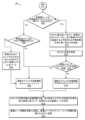
図6は、実施形態による、候補ルートから最適ルートを決定するための例示的なプロセス600を示すフロー図である。いくつかの例では、プロセス600は、上述したシステム100によって実行されてもよい。例えば、プロセス600は、ナビゲーション情報プログラム546を実行するサービス計算装置108によって実行されてもよい。あるいは、上述したように、他の実施形態では、プロセス600は、VEC105または車両計算装置104の少なくとも一方によって実行されてもよい。FIG. 6 is a flow diagram illustrating an
602において、サービス計算装置108は、車両のセンサ情報を決定し得る。例えば、サービス計算装置108は、センサのタイプ、センサの数、範囲、FOV、解像度などを決定するためのセンサ情報を車両から受信することができる。At 602, the
604において、サービス計算装置108は、車両から1以上の通信を受信することなどにより、車両の位置及び目的地を決定することができる。例えば、移動の開始時に、車両102は、その位置、目的地、センサ情報、ECU仕様などをサービス計算装置108と共有することができる。At 604, the
606において、サービス計算装置108は、目的地への候補ルートを決定し得る。例えば、ルーティング及び監視アルゴリズムは、以下で説明されるように、記述的分析レイヤまたは予測分析レイヤのいずれかで実行され得る。At 606, the
608において、サービス計算装置108は、第1の変数N=ルートの数、例えば、候補ルートの総数を表すものを設定し、第2の変数RN=1、例えば、処理のために現在選択されている候補ルートを表すカウンタとして設定することによって、第1のループを初期化することができる。At 608, the
610において、サービス計算装置108は、RNの値がNの値以上であるか否かを決定することができる。そうでない場合、プロセスはブロック612に進み、候補ルートを評価する。そうであれば、候補ルートはすべて評価され、プロセスはブロック626に進む。At 610, the
612において、サービス計算装置108は、選択されたルートを複数のウェイポイントに分割してもよい。一例として、ウェイポイントは、地図データ・データベース556に格納され得る高精細地図または標準地図上に予め定義され得る。At 612, the
614において、サービス計算装置108は、ウェイポイントの連続するペアの間のそれぞれの道路セグメントを特定することができる。各ペアのウェイポイント間の各道路セグメントの長さは、数センチメートルから数百メートルまで様々である。At 614, the
616において、サービス計算装置108は、第3の変数M=RNのセグメント数を設定し、処理のために現在選択されているセグメントを代表するカウンタとして、例えば第4の変数SM=1を設定することによって、ネストされた第2のループを初期化することができる。At 616, the
618で、サービス計算装置108は、変数SMがM以上であるかどうかを判定することができる。そうでない場合、プロセスはブロック620に進み、候補ルートの道路セグメントを評価する。そうであれば、ルートのすべての道路セグメントが評価されたことになり、プロセスはブロック624に進み、RNをインクリメントし、次の候補ルートがあれば、その処理を開始する。At 618, the
620において、サービス計算装置108は、選択された道路セグメントのPOZを決定することができる。POZを決定する方法の例は、例えば、図13~図15を参照して後述される。いくつかの例では、POZは、衝突を回避し、規制を満たし、及び/または安全を確保するために、自動車両またはロボットがその車載センサを使用して監視する必要がある、潜在的な障害物の領域、標識などを含み得る。At 620, the
622において、サービス計算装置108は、車両が620において決定されたそれぞれのPOZを監視すると予想される時間tを決定することができる。その後、プロセスは、図7で継続する。At 622, the
624において、SM=Mのとき、候補ルート内のすべてのセグメントが処理され、サービス計算装置108は、変数RNを1だけインクリメントすることができる。その後、プロセスはブロック606に戻り、すべての候補ルートが処理されたかどうか、すなわちRN=Nかどうかを判定することができる。At 624, when SM=M, all segments in the candidate route have been processed and the
626において、すべての候補ルートが処理されたとき、サービス計算装置108は、それぞれの候補ルートについて利用可能な自律走行の量に少なくとも部分的に基づいて、1または複数の最適ルートを選択し得る。例えば、選択される最適ルートは、ルートの総走行時間と比較して自律走行時間の割合が最も高いルートであってもよいし、自律走行可能としてマークされた道路セグメントの割合が最も高いルートであってもよい。さらに、場合によっては、最適ルートとしてルートを選択する際に考慮されるいくつかの要因のうち、自律走行可能な量は1つの要因に過ぎないこともある。考慮される他の要因の例としては、目的地までの総走行時間、車両の乗員の快適性、それぞれのルートを通過する際に車両が消費すると予測される燃料/エネルギの量などが挙げられる。At 626, when all the candidate routes have been processed, the
図7は、いくつかの実施形態による図6のプロセス600の続きを示すフロー図である。Figure 7 is a flow diagram illustrating a continuation of
702において、ブロック622に続いて、サービス計算装置108は、候補ルートの選択された道路セグメントについて、POZに最も近いVEC105を決定することができる。At 702, following
704において、サービス計算装置108は、選択された道路セグメントのPOZにおける車両の処理要件を決定することができる。例えば、車両を完全自動運転車両として動作させるためには、車両のセンサは、対応する道路セグメントのPOZを捕捉する視野(FOV)を有していなければならない。車両のセンサが選択された道路セグメントのPOZをカバーできない場合、サービス計算装置108は、車両102にナビゲーション情報(例えば、物体、交通、標識、信号、道路の異常など)を提供するためにVECによって取得及び処理され得る追加データ(例えば、インフラストラクチャ・センサ、他の車両のセンサ、または他のセンサからのデータ)をチェックしてもよい。At 704, the
706において、サービス計算装置108は、車両内の計算リソースが、処理される道路セグメントのPOZにおいてVEC105によって使用されるために利用可能であるか否かを決定し得る。利用可能である場合、プロセスは708に進む。そうでない場合、プロセスは710に進む。At 706, the
708において、サービス計算装置108は、評価される候補ルートが選択された場合、選択された道路セグメントのPOZに最も近いVEC105とリソース利用可能車両(RAV:Resource Available Vehicle)として車両IDを共有するように道路セグメントをマークする、または他の方法で指定することができる。したがって、時刻tにおいて、車両は、POZの近傍にある別の車両のために何らかの計算処理を実行するためにVEC105がアクセスすることができる車両であり得る。At 708, the
710において、サービス計算装置108は、車両ID及び予想時間tを、702で決定された最も近いVEC105と共有して、車両が時間tにおいてこの道路セグメントのPOZにおいてリソース要求車両(RDV:Resource Demand Vehicle)になることを示し、VEC105が車両102にリソースを提供する計算キャパシティを有するかどうかを決定することができる。At 710, the
712において、サービス計算装置108は、時間tにおいてPOZにおいて十分な計算リソースが利用可能であるか否かを示す応答を、VEC105から受信し得る。At 712, the
714において、サービス計算装置108は、VEC105が、現在評価されている道路セグメントのPOZに最も近いVECにおいて計算リソースが利用可能であることを示したか否かを判定し得る。そうである場合、プロセスは718に進む。そうでない場合、プロセスは718に進む。At 714, the
716において、サービス計算装置108は、道路セグメントを、自律走行が利用できないものとしてマークするか、または他の方法で示すことができる。例えば、示された時間tにおいて、道路セグメントのPOZに最も近いVEC105において十分な量の計算リソースが利用可能でない場合、POZを通る車両の自律運転は可能でなく、分析されている道路セグメントはそのように示される。At 716, the
718において、サービス計算装置108は、道路セグメントに、自律走行が利用可能であることをマークするか、または他の方法で示すことができる。例えば、POZに最も近いVEC105が、指示された時間tにおいて十分な計算リソースが利用可能であることを示す場合、道路セグメントは、自動運転道路セグメントであることが示される。At 718, the
720において、サービス計算装置108は、変数SMを値1だけインクリメントし、図6のブロック618に戻ることができる。たとえば、ブロック612、614、及び702~720の処理は、選択された候補ルート内のすべての道路セグメントが分析されるまで繰り返されてもよい。この処理が完了すると、ブロック618は処理をブロック624にリダイレクトして、処理のために次の候補ルートがあればそれを選択するためのルートカウンタをインクリメントする。ブロック626に関して上述したように、すべての候補ルートが処理されたとき、サービス計算装置は、車両102に送信する1以上の最適ルートを選択することができる。At 720, the
図8は、実施態様による、車両の最適ルートを選択するための例示的なアーキテクチャ及びプロセス800を示す、組み合わされたフロー図及びブロック図である。例えば、図8の例は、候補ルートに沿ってPOZを決定し、車両の車載センサ構成、車両のパワートレイン構成、及び他の車両構成情報を考慮することによって、コネクテッド車両の自動運転を最大化する安全なルートを特定するために使用され得るシステムアーキテクチャ及びデータフローを含む。いくつかのケースにおいて、図8のアーキテクチャは、図1及び図5を参照して上述したシステム100に対応し得る。データ分析プラットフォーム545は、車両、インフラストラクチャ・センサ、携帯電話、フリート会社のウェブサーバ、保険プロバイダ、政府機関、他の輸送データサービスなどの異なるソースからデータを受信する。データ分析プラットフォーム545は、記述的分析モジュール548、予測的分析モジュール550、及び処方的分析モジュール552、ならびにデータベース554及び可視化インタフェース555を含む、異なる分析レイヤに分類される異なる人工知能(AI)モジュールを使用することによって、受信したデータを処理して、エンドユーザのための値を導出することができる。さらに、データ分析プラットフォーム545は、OEMなどの他の第三者と車両データを共有することができ、地図プロバイダなどの第三者からデータ分析プラットフォーム545にデータを取り込むことができる。FIG. 8 is a combined flow diagram and block diagram illustrating an example architecture and
実施形態では、説明されるプロセスの一部は、車両計算装置104によって実行され、プロセスの別の一部は、サービス計算装置108またはVEC105によって実行されてもよい。さらに、この実施形態では、特定の機能が、それぞれ、計算装置104、105、または108のうちの1つまたは他方によって実行されるように図示されているが、機能の一部が、計算装置104、105、または108のうちの他のものによって実行されてもよいことは、本明細書の開示の利益を有する当業者には明らかである。In an embodiment, some of the processes described may be performed by
データ分析プラットフォーム545をホストするサービス計算装置108は、様々な異なるソースから様々なタイプの情報を受信することができ、また1以上のソースにデータを提供することができる。例として、インフラ情報802、ユーザ計算装置命令804、CAVセンサデータ806、旅行需要情報808、地図プロバイダ情報810、OEM情報812、及び政府機関情報814が挙げられる。上述したように、インフラ情報802は、インフラカメラ画像、及びインフラ、道路状況、建設プロジェクトなどに関するその他の情報を含むことができる。さらに、ユーザ計算装置指示804は、ウェブサイトまたはウェブアプリインタフェースなどを通じてユーザ計算装置を通じて受信されたユーザ設定、ユーザ情報、車両情報などを含むことができる。さらに、CAVセンサデータ806は、車両102または他の車両109(図8に不図示)からサービス計算装置108にデータを自動的に送信する接続されたセンサなど、コネクテッド自律車両の車両センサから直接受信されたデータを含むことができる。The
旅行需要情報808は、予定された休日、航空旅行及び鉄道旅行のチケット販売、スポーツイベント及び他のタイプのイベント販売などに部分的に基づくことができる、現在及び予想される需要に基づいて、起こり得る道路混雑の指標を提供することができる。地図提供者情報810は、高精細地図及び低精細地図、ならびに交通データなどの他の情報を含むことができる。OEM情報812は、パワートレイン情報、燃費など、特定のOEMによって生産された車両に関する様々な情報を提供することができる。政府機関情報814は、政府が提供する安全情報、交通標識情報、道路建設情報、通行止め情報などを示す場合がある。いくつかの例では、1または複数のデータ交換アプリケーションプログラミングインタフェース(API)が、上記エンティティからデータを受信するため、または上記エンティティにデータを送信するためなど、上記エンティティとデータを交換するために採用されてもよい。さらに、上述のエンティティは、情報が交換され得るエンティティ、または情報が受信され得るエンティティの例に過ぎず、他の多数の情報エンティティは、当業者には明らかである。Travel demand information 808 may provide an indication of possible road congestion based on current and forecasted demand, which may be based in part on scheduled holidays, air and rail travel ticket sales, sporting event and other types of event sales, and the like. Map provider information 810 may include high-definition and low-definition maps, as well as other information, such as traffic data.
図5を参照して上述したように、データベース554は、地図データ・データベース556、時系列データ・データベース558、画像データ・データベース560、及び車両データ・データベース562を含み得る。地図データ・データベース556に保持され得る情報の例としては、候補ルートに必要なFOVの地図、道路プロファイル地図または他の道路プロファイル情報、車両が位置する地域の高精細地図、及び車両が位置する地域の標準地図が挙げられ得る。時系列データ・データベース558に含まれ得る情報の例としては、車両CANを介して受信された情報、車両センサデータ、交通データ、天候データ、及び車両間通信(V2X)データが挙げられ得る。画像データ・データベース560に含まれ得る情報の例には、インフラストラクチャ・カメラ画像、ユーザ携帯電話カメラ画像、及びコネクテッド自動運転車両(CAV)画像が含まれ得る。車両データ・データベース562に保持され得る情報の例は、車両センサ構成情報、車両計算装置情報、車両構成情報、車両乗員情報、履歴、及び好みなどの個々の車両に関する情報を含み得る。As described above with reference to FIG. 5, databases 554 may include map data database 556, time series data database 558, image data database 560, and vehicle data database 562. Examples of information that may be held in map data database 556 may include a map of the FOV required for the candidate route, a road profile map or other road profile information, a high-resolution map of the area in which the vehicle is located, and a standard map of the area in which the vehicle is located. Examples of information that may be held in time series data database 558 may include information received via the vehicle CAN, vehicle sensor data, traffic data, weather data, and vehicle-to-everything (V2X) data. Examples of information that may be held in image data database 560 may include infrastructure camera images, user mobile phone camera images, and connected autonomous vehicle (CAV) images. Examples of information that may be held in vehicle data database 562 may include information about individual vehicles, such as vehicle sensor configuration information, vehicle computing device information, vehicle configuration information, vehicle occupant information, history, and preferences.
さらに、移動の開始時、またはそれ以前の任意の時点で、車両102は、ECU情報、パワートレイン及びシャーシ仕様などの車両構成情報530と同様に、車両センサ構成情報528に関する暗号化された情報を、サービス計算装置108に送信してもよい。例えば、車両102は、MQTT、UDPなどのブロードキャストプロトコルを使用して、この情報をサービス計算装置108に送信してもよい。さらに、車両102は、サービス計算装置108に、現在位置などの出発地位置情報及び目的地位置情報を送信してもよい。Additionally, at the start of the trip, or any time before, the
816において、データ分析プラットフォーム545において、記述的分析モジュール548は、MD5、SHA-1、SHA256などの暗号化ハッシュアルゴリズム、または任意の他の復号化技術を使用するなどして、受信した車両データを復号化することができる。復号化後、記述的分析モジュール548は、車両及び乗員の身元を認証またはその他の方法で決定することができる。例えば、認証プロセスは、データが正しいコネクテッド車両102から受信されたことを確認し、受信されたデータの完全性を検証することができる。さらに、記述的分析モジュール548は、車両データ・データベース562にアクセスして、車両データ・データベース562に保持されている車両または乗員に関する情報を取得することができる。検索され得る情報の例としては、車両102について以前に受信された可能性のある車両センサ構成情報528及び/または車両構成情報530、ならびに車両の所有者または車両の他の乗員についてのユーザ嗜好、ルーティング嗜好などが含まれ得る。さらに、図3には示していないが、記述的分析モジュール548によって実行される他のプロセスには、データ解析、データ融合などが含まれ得る。例えば、データ解析プロセスは、車両102からの受信メッセージを、さらなる処理のためにJSONフォーマットに解析することができ、これには、車両102から送信された破損したメッセージを検出して修正することが含まれる。さらに、データフィルタリング及び融合プロセスは、車両から送信されたデータを前処理し、それに応じてデータベース554を更新してもよい。At 816, in the data analytics platform 545, the descriptive analytics module 548 may decrypt the received vehicle data, such as by using a cryptographic hash algorithm, such as MD5, SHA-1, SHA256, or any other decryption technique. After decryption, the descriptive analytics module 548 may authenticate or otherwise determine the identity of the vehicle and occupants. For example, the authentication process may verify that the data was received from the correct connected
818において、記述的分析モジュール548は、車両センサ構成情報528から車両FOVを決定できる。いくつかの例では、センサ構成情報528は、車両102から受信され得、他の例では、センサ構成情報528は、車両データ・データベース562から受信され得る。例えば、センサ構成情報528は、時間の経過とともに実質的に変化する可能性が低く、したがって、以前に受信され、車両データ・データベース562に記憶されているため、ルートが決定されるたびに車両102によって送信される必要がない場合がある。At 818, the descriptive analysis module 548 can determine the vehicle FOV from the vehicle sensor configuration information 528. In some examples, the sensor configuration information 528 can be received from the
820において、記述的分析モジュール548は、受信され復号化された車両データにおいて目的地位置が指定されているか否かを判定することができる。車両の目的地が復号化された車両データで利用可能である場合、プロセスは822に進み、ルーティング及び監視を実行する。場合によっては、システムは車両乗員に目的地の入力を促し、その結果、音声認識や他のユーザ入力によって目的地が受信されることもある。一方、車両の目的地が受信した情報に含まれておらず、車両の乗員からも提供されない場合、プロセスは826に進み、目的地位置を予測してルーティング及び監視を実行する。At 820, the descriptive analysis module 548 may determine whether a destination location is specified in the received decoded vehicle data. If the vehicle destination is available in the decoded vehicle data, the process proceeds to 822 to perform routing and monitoring. In some cases, the system may prompt the vehicle occupant to input a destination, which may result in the destination being received through voice recognition or other user input. On the other hand, if the vehicle destination is not included in the received information or provided by the vehicle occupant, the process proceeds to 826 to predict a destination location and perform routing and monitoring.
822において、記述的分析モジュール548は、車両の出発地位置、目的地位置、地図、交通及び天候データの入力を受け入れ、車両が目的地位置に到達するための候補ルートを決定するルーティング及び監視アルゴリズムを実行することができる。例えば、リアルタイム交通情報は、一定の時間間隔で実行され第三者から交通データを取得する時間ループを使用して、更新され得る。交通データはデータベースに取り込まれ、ルーティング及び監視アルゴリズムに送られる。ルーティング及び監視アルゴリズムは、記述的分析モジュール548または予測的分析モジュール550のいずれかによって実行される。目的地位置が記述的分析モジュール548に提供されていない場合、ルーティング及び監視アルゴリズムは、車両の乗員の履歴、一日の時間、車両の位置などを考慮して目的地位置を予測するためのAIベースのモデルの使用に基づいて、予測的分析モジュール550によって実行され得る。目的地位置が予測され、任意選択で、車両乗員によって確認された後、ルーティング及び監視アルゴリズムは、826に関して後述するように、目的地位置への候補ルートを生成するために実行されてもよい。At 822, the descriptive analytics module 548 can execute a routing and monitoring algorithm that accepts inputs of the vehicle's origin location, destination location, map, traffic and weather data and determines candidate routes for the vehicle to reach the destination location. For example, real-time traffic information can be updated using a time loop that runs at regular time intervals and obtains traffic data from a third party. The traffic data is captured in a database and sent to the routing and monitoring algorithm. The routing and monitoring algorithm is executed by either the descriptive analytics module 548 or the predictive analytics module 550. If the destination location is not provided to the descriptive analytics module 548, the routing and monitoring algorithm can be executed by the predictive analytics module 550 based on the use of an AI-based model to predict the destination location taking into account the vehicle occupant's history, time of day, vehicle location, etc. After the destination location is predicted and, optionally, confirmed by the vehicle occupant, the routing and monitoring algorithm may be executed to generate candidate routes to the destination location, as described below with respect to 826.
824において、記述的分析モジュール548は、さらに、様々な外部ソース802~814からデータを受信し、受信したデータの認証、フィルタリング、及び/または融合を実行し得る。例えば、データ分析プラットフォーム545は、データフィルタリング及びデータ融合を使用して、交通インフラストラクチャ、ユーザスマートフォン、サードパーティなどから得られる様々なタイプの時系列データ及び画像データを取り込むことができる。一例として、外部ソース802~814の少なくとも一部とデータを交換するために、1つ以上のブロックチェーンネットワークを使用することができる。データは取り込まれ、データベース554などに格納されてもよい。いくつかの非限定的な例として、データは、データ分析プラットフォーム545の優れたリアルタイム性能を達成するために、SQL(Structured Query Language)と非SQLデータベースの組み合わせを使用して管理されてもよい。At 824, the descriptive analytics module 548 may further receive data from various external sources 802-814 and perform authentication, filtering, and/or fusion of the received data. For example, the data analytics platform 545 may use data filtering and data fusion to ingest various types of time series and image data obtained from transportation infrastructure, user smartphones, third parties, etc. As an example, one or more blockchain networks may be used to exchange data with at least some of the external sources 802-814. The data may be ingested and stored in a database 554 or the like. As some non-limiting examples, the data may be managed using a combination of Structured Query Language (SQL) and non-SQL databases to achieve superior real-time performance of the data analytics platform 545.
826において、目的地位置が車両102から受信された受信情報に含まれていない場合、予測的分析モジュール550は、機械学習モデル、ルールベースのモデルなどを使用することによって、及び/または車両乗員プロファイル、過去のトリップデータ、時間帯、及び/または車両データ・データベース562に格納された他の情報に基づいて、目的地位置を予測してもよい。予測された目的地は、サービス計算装置108によって、車両計算装置104に関連付けられた音声アシスタントまたは他のヒューマン・マシン・インタフェースに送信されてもよい。一例として、予測された目的地の確認を得るための対話型音声要求が車両乗員に送信されてもよい。予測的分析モジュール550は、予測された目的地位置の確認、または代替の目的地位置を示すユーザ入力を受け取ることができる。目的地位置の決定後、予測的分析モジュール550は、出発地位置と目的地位置との間の候補ルートを決定するために、ルーティング及び監視を実行することができる。候補ルートを決定する例については、図11を参照して説明する。At 826, if the destination location is not included in the received information received from the
828において、サービス計算装置108は、候補ルートの各々について速度プロファイルを決定し得る。速度プロファイルは、各候補ルートについて車両速度を予測するために決定されてもよく、予測的分析モジュール550によって実行されてもよい。速度プロファイルは、予測的分析レイヤまたは記述的分析レイヤのルーティング及び監視アルゴリズムからの最も更新された車両ルートに基づいて決定される。ルートの道路セグメントごとに、速度予測モデルを使用して車両速度を予測してもよく、速度予測モデルには、機械学習モデル、統計モデル、またはルールベースのモデルのうちの1つ以上が含まれ得る。速度予測モデルへの追加入力には、現在の道路セグメントのリアルタイム交通量とトリップ履歴が含まれる場合がある。リアルタイムの交通速度は、地図データプロバイダなどのサードパーティデータプロバイダから取得することができる。候補ルートの速度プロファイルは、それぞれの候補ルートにおける各道路セグメントの予測速度を格納することによって取得することができる。さらに、この処理をすべての候補ルートに対して実行してもよい。At 828, the
830において、出発地位置と目的地位置との間で候補ルートが決定された後、計算装置は、候補ルートを道路セグメントに分割してもよく、各候補ルートの各セグメントについてPOZを決定してもよい。例えば、データ分析プラットフォーム545がコネクテッド車両の目的地を特定した後、POZ決定アルゴリズムが実行されて、完全にまたは部分的に自動化された車両(ロボット、ドローンなどを含み得る)が、衝突を回避し、規制を満たし、安全を確保するために、車載センサを使用して監視する必要がある、候補ルートの各々の道路セグメントについて、潜在的な障害物、標識、交通信号機などの領域を決定してもよい。上述したように、各候補ルートは、連続する2つのウェイポイント/ノード間の距離である複数の道路セグメントに分割されてもよい。ルートウェイポイントまたはノードは、地図データ・データベース556に含まれる高精細地図または標準地図に基づいて定義することができる。道路セグメントと同様にルートウェイポイントも、本明細書のルーティング及び監視プロセスによって定義されてもよい。しかしながら、これらの特徴を決定することは、図8の830における予防観測ゾーン(POZ)プロセスによっても実行され得る。POZプロセスの主なタスクは、自動運転車両がそれぞれの道路セグメントを通過する際に監視すべき、各道路セグメントに必要な観測ゾーンボリュームを計算することであってもよい。After the candidate routes are determined between the origin and destination locations at 830, the computing device may divide the candidate routes into road segments and determine a POZ for each segment of each candidate route. For example, after the data analytics platform 545 identifies the destination of the connected vehicle, a POZ determination algorithm may be executed to determine areas of potential obstacles, signs, traffic signals, etc., for each road segment of the candidate route that a fully or partially automated vehicle (which may include a robot, drone, etc.) needs to monitor using on-board sensors to avoid collisions, meet regulations, and ensure safety. As described above, each candidate route may be divided into multiple road segments, which are the distance between two consecutive waypoints/nodes. The route waypoints or nodes may be defined based on high-definition or standard maps contained in the map data database 556. The route waypoints as well as the road segments may be defined by the routing and monitoring process of the present specification. However, determining these features may also be performed by the preventive observation zone (POZ) process at 830 in FIG. 8. The main task of the POZ process may be to calculate the required observation zone volume for each road segment that should be monitored as the autonomous vehicle traverses each road segment.
いくつかのケースにおいて、予測的分析モジュール550によって実行されるプロセスは、2つの異なる階層レベルに分類され得る。例えば、ルーティング及び監視826、予防観測ゾーンの決定830、及び速度プロファイルの決定828は、第1の階層レベルに対応し得る。さらに、計算要件の決定は、第2の階層レベルに対応し得る。第1の階層レベルの処理の目的は、第2の階層レベルの要件を決定するために必要とされる特徴を決定することであってよい。その後、最適なルートを選択するために計算要件が考慮され得る。さらに、いくつかの例では、最適ルートを選択するために他のパラメータが考慮されてもよい。このようなパラメータの例には、安全スコアの決定、効率の決定、コストの決定、距離の決定、移動時間の決定、排出量の決定などが含まれる。これらのパラメータは、候補ルートの各々について決定されてもよい。いくつかの例では、決定されたパラメータは、各候補ルートの自動運転時間量に加えて、目的地までの最適ルートを特定するために考慮すべき追加要素として使用するために、処方的分析モジュール552に提供されてもよい。In some cases, the processes performed by the predictive analytics module 550 may be categorized into two different hierarchical levels. For example, the routing and monitoring 826, the determination of preventive observation zones 830, and the determination of speed profile 828 may correspond to a first hierarchical level. Furthermore, the determination of computational requirements may correspond to a second hierarchical level. The purpose of the processing of the first hierarchical level may be to determine the characteristics required to determine the requirements of the second hierarchical level. The computational requirements may then be considered to select the optimal route. Furthermore, in some examples, other parameters may be considered to select the optimal route. Examples of such parameters include determining a safety score, determining efficiency, determining costs, determining distance, determining travel time, determining emissions, etc. These parameters may be determined for each of the candidate routes. In some examples, the determined parameters may be provided to the prescriptive analytics module 552 for use as additional factors to be considered to identify the optimal route to the destination in addition to the amount of automated driving time for each candidate route.
842において、予測的分析モジュール550によって決定された候補ルート及び追加パラメータは、1または複数の最適ルートを決定し得る処方的分析モジュール552で受信され得る。いくつかの例では、処方的分析モジュール552は、少なくとも、ルートを通過するときに車両の自律走行量を最大化するルートを決定することに基づいて、最適ルートを決定し、出力することができる。いくつかの例では、自律走行量に適用される重み付けに加えて、安全スコア、効率、総移動時間などの様々なパラメータに重み付けを適用することなどにより、各候補ルートについて上述した追加パラメータの1以上も考慮されてよい。または、いくつかの例では、機械学習モデルが最適ルートを選択するように訓練されることもある。別の選択肢として、車両乗員の好みも重み付けを受けることがある。いくつかの例では、処方的レイヤのルート推薦機能は、各ルートの自動運転時間の最大量だけでなく、すべてのルートの速度プロファイル(したがって移動時間)を考慮してもよく、これらの考慮事項に基づいて車両に最適なルートを選択してもよい。速度に加えて、車両効率、(快適性レベルを推定するための)車両ダイナミクス、コスト、距離、及び排気を含む他の特徴も、最適ルートを決定する際に考慮される可能性があることに留意されたい。いくつかのケースにおいて、ルート最適化は組み合わせ問題として扱われることもあり、この場合、厳密な最適解は、パラメータの集合が少ない問題に対してのみ達成される。したがって、実際には、ヒューリスティックに基づくアプローチは、最適性を保証することなく適用することができるが、生成ソリューションの最良の結果を導くことが多い。本明細書のいくつかの例では、大きな最適化パラメータ空間を持つルーティングの大域的/局所的最適を達成するために機械学習を採用し、実現可能な結果を保証するためにルールベースのヒューリスティックを採用することができる。コネクテッド車両のルートの更新ごとに、計算装置は、車両IDとそのステータスを、選択されたルートの最も近いVECと共有することができる。At 842, the candidate routes and additional parameters determined by the predictive analytics module 550 may be received by a prescriptive analytics module 552, which may determine one or more optimal routes. In some examples, the prescriptive analytics module 552 may determine and output an optimal route based at least on determining a route that maximizes the amount of autonomous driving of the vehicle when traversing the route. In some examples, in addition to the weighting applied to the amount of autonomous driving, one or more of the additional parameters described above may also be considered for each candidate route, such as by applying weighting to various parameters such as safety score, efficiency, total travel time, etc. Alternatively, in some examples, a machine learning model may be trained to select the optimal route. As another option, the preferences of the vehicle occupants may also be weighted. In some examples, the route recommendation function of the prescriptive layer may consider the speed profile (and therefore travel time) of all routes, as well as the maximum amount of autonomous driving time for each route, and may select the optimal route for the vehicle based on these considerations. It should be noted that in addition to speed, other features including vehicle efficiency, vehicle dynamics (to estimate comfort levels), cost, distance, and emissions may also be considered in determining the optimal route. In some cases, route optimization may be treated as a combinatorial problem, where a strict optimal solution is achieved only for problems with a small set of parameters. Thus, in practice, heuristic-based approaches may be applied without guaranteeing optimality, but often lead to the best results of generative solutions. Some examples herein may employ machine learning to achieve global/local optima for routing with a large optimization parameter space, and rule-based heuristics to ensure feasible results. For each route update of the connected vehicle, the computing device may share the vehicle ID and its status with the nearest VEC of the selected route.
サービス計算装置108は、選択された最適ルートを車両計算装置104に送信してもよい。車両計算装置104は、目的地位置へのナビゲーションに使用するために、選択されたルートを車両102の車両制御プログラム524に提供することができる。The
844において、計算装置は、車両ID及び予測時間tを、選択されたルートに沿って識別されたPOZのVEC105に送信し、それぞれのVEC105のPOZを通過するときに、車両がリソース利用可能車両(RAV)であるかリソース要求車両(RDV)であるかを示すことができる。いくつかの例では、車両をRDVとして指定することで安全サイドを誤る可能性があるような不確実性を考慮して、これらの指定に閾値を適用することができる。例えば、車両が計算上の要件を満たすと判定された場合でも、1%または数%ポイント、または他の適切な閾値のように、車両は安全バッファを提供するためにRDVとして指定され得る。他の例として、車両をRAV(利用可能なリソース)として指定する場合、VEC105がRAVにタスクの実行を要求したときにタスクがRAVのキャパシティをオーバしないように、リソースのオーバキャパシティが超える閾値を適用してもよい。このように、オーバキャパシティの閾値は、RAVが、RAV自身の航行安全に影響を与えることなく、要求された計算支援を提供できることを保証することができる。At 844, the computing device may transmit the vehicle ID and the predicted time t to the
図9は、実施形態による、候補ルートから最適ルートを決定するための例示的なプロセス900を示すフロー図である。いくつかの例では、プロセス900は、上述したシステム100によって実行されてよい。例えば、プロセス900は、ナビゲーション情報プログラム546を実行するサービス計算装置108によって実行されてよい。プロセス900は、上述したプロセス600に対する詳細を提供し、図5及び図8に関して上述したようなデータ分析プラットフォーム545にマッピングされてもよい。9 is a flow diagram illustrating an
902において、サービス計算装置108は、出発地、目的地、センサ構成、及び車両仕様などの車両情報を、記述的分析モジュールにおいて受信することができる。At 902, the
904において、サービス計算装置108は、受信された情報を復号化し、認証することができる。At 904, the
906において、サービス計算装置108は、車両センサのFOVを決定することができる。例えば、車両センサの仕様は、車両センサのFOVを特定するために「車両FOV」モジュールに送られ、これは「ルーティング&監視」モジュールに渡される。At 906, the
908において、サービス計算装置108は、車両計算リソースの量を決定することができる。At 908, the
910において、サービス計算装置108は、車両の目的地が、受信された情報において示されたか否かを判定することができる。そうである場合、プロセスは914に進む。そうでない場合、プロセスは912に進む。車両の目的地が復号化された車両データにおいて利用可能である場合、記述的分析におけるルーティング及び監視モジュールは、車両の位置、目的地、地図、交通及び天候データの入力を受け入れ、車両が目的地に到達するための潜在的なルートを決定する。At 910, the
912において、サービス計算装置108は、以前の移動、時間帯、曜日などに基づいて、目的地を予測することができる。あるいは、問い合わせが車両の乗員に送信されることもある。At 912, the
914において、サービス計算装置108は、目的地までの候補ルートを決定し、各候補ルートについてウェイポイント及び道路セグメントを決定し得る。候補ルートを決定する例については、図11を参照して後述する。ルーティング及び監視モジュールは、ルート予測のために、リアルタイム交通情報の入力及び確認された目的地の入力を受け取ることができる。リアルタイム交通情報は、一定の時間間隔で実行される時間ループを使用して更新され、サードパーティから交通データを取得し、このトラフィックデータはデータベースに取り込まれ、ルーティング及び監視モジュールに送信される。目的地が記述的または予測的なルーティング及び監視モジュールによって確定されると、ルーティング及び監視モジュールでは、ルーティングエンジンを使って、出発地から目的地までの候補ルートが計算される。候補ルートはその後、予測レイヤのPOZ決定機能と速度プロファイル決定機能に送られる。At 914, the
916において、サービス計算装置108は、各候補ルートについて、各道路セグメントのPOZを決定することができる。一例は、図12~図14を参照して後述される。例えば、POZは、自動車両が道路セグメントを通過する際に監視する必要がある道路セグメントの部分であってもよい。At 916, the
918において、サービス計算装置108は、各道路セグメントのPOZを車両センサのFOVと比較することによって、各候補ルートの各道路セグメントの安全スコアを決定することができる。安全スコアは、各POZのどの程度の割合が車両センサのFOVによってカバーされ得るかを示す。自動運転の場合、車両のFOVはPOZ全体をカバーする必要がある。車両FOVが特定の道路セグメントのPOZをカバーできない場合、計算装置108は、車両が特定の道路セグメントを通過すると予想される時間を決定し、特定の道路セグメントに対するVEC105と通信して、VEC105がその特定の道路セグメントに対する自動運転を実現するために車両をサポートできるかどうかを決定することができる。At 918, the
例えば、車両センサFOVが特定の道路セグメントのPOZをカバーしない場合、計算装置108は、車両の車載センサが監視できず、POZのその領域を監視するための外部サポートを必要とするPOZの領域を決定する。計算装置108は、POZの場所に、カバーされていない領域のセンシングを実行するためにVEC105がアクセスして使用することができる対応するインフラストラクチャ・センサがあるかどうかをチェックする。計算装置108はまた、対応する道路セグメントが、コネクテッド車両がサポートを必要とするPOZのカバーされていない領域について追加のセンサデータを有するか否かをチェックすることができる。VEC105がPOZの未カバー領域について必要なセンサ情報にアクセスできる場合、計算装置108は、特定のVEC105に要求を送信して、その道路セグメントの通過中にVEC105が車両を支援するように要求することができる。VECが道路セグメントのPOZのカバーされていない領域のセンサ情報にアクセスできないが、サービス計算装置108が必要な画像、特徴、及び/または検出データにアクセスできる場合、サービス計算装置108は、VEC105が道路セグメントでの自動運転のために車両を支援するためのデータを処理するために、このデータを特定のVEC105に提供することができる。VEC105とサービス計算装置108の両方が、POZのカバーされていない部分をカバーするセンサにアクセスできない状況では、計算装置108は、安全スコアを計算し、その道路セグメントについて手動運転が実行されるべきであることを示すことができる。例えば、自動運転を実現するための道路セグメントのPOZにおいて、車載センサのFOVによるカバー、あるいは車載センサのFOVのカバーと、VEC105などでデータ処理された外部センサによるカバーの組み合わせにより、センサのフルカバレッジとデータ処理が可能であれば、道路セグメントの安全スコアは最大となる。For example, if the vehicle sensor FOV does not cover the POZ of a particular road segment, the
920において、サービス計算装置108は、各候補ルートの各道路セグメントの各POZに必要な計算リソースを決定することができる。例えば、計算装置108は、その道路セグメントでの自動運転のためのPOZ検出、認識、経路計画、車両制御などの要件を考慮して、車両の計算要件を計算することができる。車載のセンサデータの処理に加えて、計算要件は、自動運転の知覚要件のために処理される必要がとなり得る外部の計算装置及び/または他の車両からの追加の接続データも考慮することができる。At 920, the
922において、サービス計算装置108は、車両センサ及び計算リソースを各POZに必要なリソースと比較することによって、各候補ルートの各POZにおいて車両のステータスをRAVまたはRDVとして決定することができる。例えば、計算装置は、計算要求と車両の利用可能な計算リソースとを比較し、各道路セグメントについて車両を少なくとも2つのカテゴリ、すなわちリソース要求車両(RDV)またはリソース利用可能車両(RAV)のうちの1つに分類してもよい。場合によっては、第3のカテゴリ、例えば、ナビゲーションのための支援を必要としないが、VECと共有するための利用可能なリソースを持たないリソース充足車両(RMV:Resources Met Vehicle)が含まれることもある。RDVが特定の道路セグメントを自律走行するために必要な車両機能をリアルタイムで実行できるようにするために、RDVは外部デバイスによっていくつかのセンシングタスク及び/または計算タスクを実行させる必要がある。RAVは、利用可能なリソースを利用して、RDVまたは特定の道路セグメントのVEC105のタスクを実行するように要求されることがある。RMVは、上述したオーバキャパシティ閾値を満たすにはリソースのオーバキャパシティが不十分であり、特定の道路セグメントに沿った自動運転に必要なタスクを実行するのに十分な量のリソースのみ持つ車両である。At 922, the
924において、サービス計算装置108は、車両が各候補ルートの各道路セグメントの各POZを通過すると予想される時間tを決定することができる。At 924, the
926において、サービス計算装置108は、各候補ルートの各道路セグメントについて、各POZに最も近いVECを決定し得る。At 926, the
図10は、いくつかの実施態様による図9のプロセス900の続きを示すフロー図である。Figure 10 is a flow diagram illustrating a continuation of
1002において、サービス計算装置108は、各候補ルートの各道路セグメントについて、車両ステータスがRDV(リソース要求車両)であるか否かを判定することができる。そうである場合、プロセスは1010に進む。そうでない場合、プロセスは1004に進む。At 1002, the
1004において、サービス計算装置108は、車両のRAVステータスが閾値を超えるか否かを判定することができる。例えば、車両で利用可能なリソースの量は、VEC105がRAVステータスを有する車両のリソースを使用するために、閾値を超えることが要求される場合がある。その場合、プロセスは1006に進む。そうでない場合、プロセスは1008に進む。At 1004, the
1006において、サービス計算装置108は、車両ID及び時間tを、リソースを共有できるRAV(リソース利用可能車両)としてそれぞれのVEC105と共有するために、道路セグメントをマークすることができる。たとえば、車両が道路セグメントを通過すると計算される時間に基づいて、計算装置108は、車両計算リソースステータスをVEC105と共有することができる。車両ステータスがRAVである場合、対応する道路セグメントの最も近いVEC105は、車両IDをリストアップし、車両が道路セグメントを通過している間、VECキャパシティの一部としてその利用可能なリソースを利用することを検討してもよい。At 1006, the
1008において、サービス計算装置108は、道路セグメントを自動運転セグメント(最高安全スコアに対応)としてマークすることができる。At 1008, the
1010において、サービス計算装置108は、POZに最も近いVEC105に、車両ID、RDV(リソース要求車両)ステータス、及び車両がPOZを通過すると予想される予想時間tを含む問い合わせを送信し、VEC105が時間tにおいて車両にリソースを提供できるかどうかを決定し得る。例えば、道路セグメントの車両ステータスがRDVと表示された場合、計算装置108は、道路セグメントに最も近いVEC105と車両IDを共有し、VEC105が自動運転の車両を支援するための利用可能なリソースを持っているかどうかを確認する。At 1010, the
1012において、サービス計算装置108は、VEC105から応答を受信することができる。VEC105が、車両を支援するために計算された時間tにおいて利用可能なリソースを有する場合、計算装置108は、その道路セグメントを自動運転道路セグメントとしてリストアップする。そうでない場合、その道路セグメントは、非自動運転または手動運転の道路セグメントとしてリストアップされる。At 1012, the
1014において、サービス計算装置108は、VEC105が、時間tにおいて、車両のためにVEC105において十分なリソースが利用可能であることを示したか否かを判定し得る。そうである場合、プロセスは1008に進む。そうでない場合、プロセスは1016に進む。At 1014, the
1016において、サービス計算装置108は、道路セグメントを自動運転が利用できないセグメントとしてマークすることができる。At 1016, the
1018において、サービス計算装置108は、少なくとも、利用可能な自動運転の量、及び安全スコアなどの指定され得る他の要因に基づいて、車両のための最適ルートを決定し得る。一例として、計算装置108は、自動運転時間の割合が最も高いルートを選択してもよい。At 1018, the
1020において、サービス計算装置108は、最適ルート情報を車両に送信し、最適ルートのスケジューリング情報を関連するVEC105に送信することができる。At 1020, the
図11は、実施形態による、出発地位置と目的地位置との間の候補ルートを決定する例1100を示す。この例では、地図1102上に示されているように、出発地位置1104と目的地位置1106が最初に決定され得る。例えば、出発地位置1104及び目的地位置1106が設定された後、複数の実現可能な候補ルート1108が決定されてよい。この例では、2つの実現可能な候補ルート1108、すなわち、第1のルート1110及び第2のルート1112が図示されている。他の例では、より多くのまたはより少ない候補ルートが決定されてよい。さらに、実現可能な候補ルートが非常に多数ある場合には、各ルートに沿って移動した推定距離、各ルートの推定移動時間など、様々な閾値のいずれかを用いて候補ルートの数を絞り込むことができる。場合によっては、絞り込み基準は、少なくとも部分的にユーザの好みに基づいてもよい。11 illustrates an example 1100 of determining candidate routes between an origin location and a destination location, according to an embodiment. In this example, an origin location 1104 and a destination location 1106 may be first determined, as shown on a map 1102. For example, after the origin location 1104 and the destination location 1106 are set, a number of feasible candidate routes 1108 may be determined. In this example, two feasible candidate routes 1108 are illustrated, namely a first route 1110 and a second route 1112. In other examples, more or fewer candidate routes may be determined. Furthermore, if there are a large number of feasible candidate routes, the number of candidate routes may be narrowed down using any of a variety of thresholds, such as an estimated distance traveled along each route, an estimated travel time for each route, etc. In some cases, the narrowing criteria may be based at least in part on a user's preferences.
各ルート1110及び1112は、ウェイポイント1114と、2つのウェイポイント1114間の距離である介在道路セグメント1116とに基づいて、複数のセグメントに分割することができる。ウェイポイント1114の位置と各道路セグメント1116の長さは、通過する道路の種類に少なくとも部分的に依存する場合がある。例えば、道路セグメント1116は、1メートル未満のものから数百メートル以上のものまで様々である。場合によっては、ウェイポイント1114は交差点に対応することもあるが、交差点がなくとも短い道路セグメントに分かれているような長い道路など、必ずしもそうとは限らない。Each route 1110 and 1112 can be divided into multiple segments based on waypoints 1114 and intervening road segments 1116, which are the distance between the two waypoints 1114. The location of the waypoints 1114 and the length of each road segment 1116 may depend at least in part on the type of road traversed. For example, the road segments 1116 may vary from less than a meter to hundreds of meters or more. In some cases, the waypoints 1114 may correspond to intersections, but this is not necessarily the case, such as long roads that may be divided into shorter road segments without any intersections.
図示の例では、第1のルート1110は、ウェイポイント1114(A1)、1114(A2)、1114(A3)、1114(A4)と、道路セグメント1116(A1)、1116(A2)、1116(A3)、1116(A4)とを含む4つの道路セグメントに分割されている。さらに、第2のルート1112は、ウェイポイント1114(B1)、1114(B2)、1114(B3)と、道路セグメント1116(B1)、1116(B2)、1116(B3)とを含む3つの道路セグメントに分割される。上述のように、他の例では、ルート1110、1112の各々に対して異なる数のウェイポイント及び道路セグメントが使用され得る。さらに、説明のために地図1102が図11に図示されているが、運用上、サービス計算装置108が、選択されたルート及び道路セグメントの識別及び分析を実行するための視覚的な地図を生成する必要はない。In the illustrated example, the first route 1110 is divided into four road segments including waypoints 1114(A1), 1114(A2), 1114(A3), 1114(A4) and road segments 1116(A1), 1116(A2), 1116(A3), 1116(A4). Additionally, the second route 1112 is divided into three road segments including waypoints 1114(B1), 1114(B2), 1114(B3) and road segments 1116(B1), 1116(B2), 1116(B3). As mentioned above, in other examples, a different number of waypoints and road segments may be used for each of the routes 1110, 1112. Additionally, although a map 1102 is illustrated in FIG. 11 for illustrative purposes, operationally, the
データ分析プラットフォーム545は、地理的地域内のすべての候補ルートまたは少なくとも最も実現可能な候補ルートについて、各ウェイポイント1114及び/または道路セグメント1116のデータを事前に記憶しておいてもよい。例えば、データ分析プラットフォーム545は、各地図に含まれる道路上のルート及び可能性のあるウェイポイント及び道路セグメントを決定するために、地理的地域の地図を事前に分析してもよい。この情報は、車両からのルート案内の要求を受信する前に、図5及び図8を参照して上述した地図データ・データベース556に格納されてもよい。The data analytics platform 545 may pre-store data for each waypoint 1114 and/or road segment 1116 for all possible routes or at least the most feasible possible routes within a geographic region. For example, the data analytics platform 545 may pre-analyze maps of the geographic region to determine routes and possible waypoints and road segments on the roads contained in each map. This information may be stored in the map data database 556 described above with reference to FIGS. 5 and 8 prior to receiving a request for route guidance from a vehicle.
さらに、各地図で識別された決定された道路セグメント1116について、データ分析プラットフォーム545は、それぞれの道路セグメント1116のPOZを事前に決定し、記憶してもよい。例えば、各ルートの道路セグメントが計算されると、データ分析プラットフォーム545は、道路交差点の数及び対応する交差点機能領域を計算してもよい。本明細書の例では、交差点は、交差点の物理的領域と交差点の機能的領域の2つの領域を含む場合がある。POZは、各交差点について計算されてもよく、そのそれぞれの道路セグメント1116をナビゲートするときに人の運転手または車両センサによって監視されるべき3Dゾーンを含んでもよい。例えば、自律車両は、それぞれの道路セグメント1116を自律的に安全に走行するためにPOZを監視することが期待され得る。Additionally, for each determined road segment 1116 identified in each map, the data analytics platform 545 may pre-determine and store the POZ for each road segment 1116. For example, as the road segments for each route are calculated, the data analytics platform 545 may calculate the number of road intersections and the corresponding intersection functional areas. In the example herein, an intersection may include two areas: the physical area of the intersection and the functional area of the intersection. A POZ may be calculated for each intersection and may include a 3D zone to be monitored by a human driver or vehicle sensors when navigating its respective road segment 1116. For example, an autonomous vehicle may be expected to monitor the POZ to safely navigate its respective road segment 1116 autonomously.
このルーティング例では、以下で説明されるように、第1のルート1110及び第2のルート1112について、データ分析プラットフォーム545は、各ルート1110、1112の各セグメントについてPOZを決定するために、分析レイヤにおいてPOZ決定プロセスを実行してもよい。車両センサFOVは、図8に関して上述したような、車両102についてデータ分析プラットフォーム545によって受信された車両センサ構成情報528に基づいて、データ分析プラットフォーム545によって計算されてもよい。In this routing example, for the first route 1110 and the second route 1112, the data analytics platform 545 may perform a POZ determination process in the analytics layer to determine a POZ for each segment of each route 1110, 1112, as described below. The vehicle sensor FOV may be calculated by the data analytics platform 545 based on the vehicle sensor configuration information 528 received by the data analytics platform 545 for the
図12Aと図12Bは、いくつかの実施態様による交差点の例を示している。図12Aは、いくつかの実施態様による交差点1200の例を示す。交差点1200は、ハッチングで示された交差点機能領域1202を含む。交差点機能領域1202は、交差点の交差点物理領域1204(破線で示される)と、車両1208が操縦することができる交差点物理領域1204の外側の追加領域1206との両方を含むハッチングされた領域を含むことができる。したがって、交差点物理領域1204は、交差点1200の四隅内の固定領域に対応し得る。一方、全体的な機能領域1202は可変であってもよく、図12Bに示すように、上流部分1210及び下流部分1212を含んでもよい。12A and 12B show an example of an intersection according to some embodiments. FIG. 12A shows an example of an intersection 1200 according to some embodiments. The intersection 1200 includes an intersection
図12Bは、実施態様による例示的な交差点1220を示す。上述したように、交差点1220の固定された物理領域1204とは逆に、交差点機能領域1202は可変であり、物理領域1204に加えて上流部分1210と下流部分1212の両方を含む。交差点機能領域1202の上流部分1210は、機能長1222を含む。機能長1222は、車両1208が交差点1220に接近し、その間に車両1208が減速して完全に停止する場合など、いくつかの部分に分割されてもよい。これらの部分には、知覚反応距離1224及び操縦(maneuver)距離1226が含まれる。さらに、機能長1222は、他の車両1230が待ち列をなしている交差点機能領域1202の一部分であり得るストレージ(storage)距離1228を含むことができる。12B illustrates an
事故は交差点で発生することが多いため、交差点での安全性の確保は最優先事項である。交差点では、人間の運転手は、どこで車線変更を行うか、いつ、どのように信号を読むか、停止する場所、曲がる前に見るべき場所、曲がるタイミングと速度などを理解することができる。自動運転車両は、人間のような判断を下すために、連続したステップに従い、適切な領域を観察する能力を持つべきである。従って、自動運転車両は、政府、地方自治体などが指定する交差点の異なる領域を理解し、各領域に対して人間の運転手と同じ動作を行う必要がある。交差点機能領域の計算は、各国の指定当局によって定義される道路制限速度、場所、道路の種類などに依存し得る。米国では、AASHTO(米国道路交通運輸行政官協会)によると、交差点機能長(F)は、EQ(1)に示すように、停止見通し距離(S)とストレージ長距離(Q)の和である。交通がない場合、ストレージ長距離(Q)はゼロとなり、交差点機能領域は停止見通し距離となる。停止見通し距離は、車両を停止させるための2つのフェーズで車両が移動する距離の組み合わせであり、すなわち、第1のフェーズは知覚反応時間中に移動する知覚反応距離1224であり、第2のフェーズは操縦時間中に移動する操縦距離1226である。
F=S+Q EQ(1)
S=(1.47*V*t)+1.075*(V2/a) EQ(2) Accidents often occur at intersections, so ensuring safety at intersections is a top priority. At an intersection, a human driver can understand where to change lanes, when and how to read the signal, where to stop, where to look before turning, when and how fast to turn, etc. An autonomous vehicle should have the ability to follow successive steps and observe the appropriate area to make a human-like decision. Therefore, an autonomous vehicle needs to understand the different areas of an intersection designated by the government, local government, etc., and perform the same actions as a human driver for each area. The calculation of the intersection functional area may depend on the road speed limit, location, road type, etc., defined by the designated authorities of each country. In the United States, according to AASHTO (American Association of Highway and Transportation Officials), the intersection functional length (F) is the sum of the stopping sight distance (S) and the storage long distance (Q), as shown in EQ (1). When there is no traffic, the storage long distance (Q) is zero, and the intersection functional area is the stopping sight distance. The stopping visibility distance is a combination of the distance traveled by the vehicle in two phases to stop the vehicle: the first phase is the perceived
F=S+Q EQ(1)
S=(1.47*V*t)+1.075*(V2 /a) EQ(2)
F=交差点機能長
S=停車時見通し距離
Q=ストレージまたは待ち列長
V=設計速度(マイル)
t=知覚反応時間(2.5秒)
a=減速率(11~15フィート/sec2以内、例:11.2フィート/sec2) F = Intersection functional length S = Stopping visibility distance Q = Storage or queue length V = Design speed (mph)
t = Perceptual reaction time (2.5 seconds)
a = Deceleration rate (within 11 to 15 feet/sec2 , e.g. 11.2 feet/sec2 )
EQ(2)の最初の部分は、運転手が知覚反応距離1226を通過し、判断が必要であることを認識し、どのような操縦が適切であるかを決定する知覚反応時間の間に移動した距離を示す。知覚反応時間は、典型的には、知覚のための約1.5秒と反応のための約1.0秒を含む約2.5秒である。EQ(2)の第2部分は、車両を減速して完全に停止するための操縦距離の間に運転手が移動した距離を示し、例えば、ストレージ距離1228内に他の車両1203がある場合は1232で、ストレージ距離1228内に他の車両がない場合は1234で示す。The first part of EQ(2) shows the distance traveled by the driver during the perceptual reaction time to pass the
図13は、実施形態による、異なる基準についてPOZを決定するための例示的なプロセス1300を示すフロー図である。いくつかの例では、プロセス1300は、上記システム100によって実行されてよい。例えば、プロセス1300は、ナビゲーション情報プログラム546を実行するサービス計算装置108などのデータ分析プラットフォーム545によって実行されてもよい。コネクテッド車両がその現在位置及び目的地を共有すると、対応する道路セグメントが、目的地位置へのすべての候補ルートについてデータ分析プラットフォーム545によって計算され得る。道路セグメントは、(1)任意の交差点機能領域の外側の道路セグメントと、(2)交差点機能領域の内側の道路セグメントと、に分けられる。予測的データ分析レイヤのPOZ決定プロセス1329は、最初に道路セグメントのタイプを特定し、次にその道路セグメントのPOZを計算してもよい。システムは、各候補ルートの各道路セグメントについて少なくとも1つのPOZを決定してよい。13 is a flow diagram illustrating an
1302において、サービス計算装置108は、車両計算装置104から、現在位置及び目的地を含む車両情報を受信することができる。At 1302, the
1304において、サービス計算装置108は、候補ルート、ウェイポイント、及び交差点の機能領域を決定することができる。At 1304, the
1306において、サービス計算装置108は、ウェイポイントに基づいて現在のセグメントを決定することができる。At 1306, the
1308において、サービス計算装置108は、現在のセグメントが交差点の機能領域内にあるかどうかを決定することができる。そうである場合、プロセスは1316に進む。そうでない場合、プロセスは1310に進む。At 1308, the
1310において、サービス計算装置108は、現在のセグメントのV(設計速度)及びG(道路勾配)を決定することができる。At 1310, the
1312において、サービス計算装置108は、1310で決定されたV及びGの値に基づいて、停止見通し距離Sを決定することができる(以下のEQ(5)参照)。At 1312, the
1314において、サービス計算装置108は、現在のセグメントのPOZ_STを決定することができる(例えば、セグメントは交差点機能領域外である)。At 1314, the
1316において、現在のセグメントが交差点の機能領域内にある場合、サービス計算装置108は、機能領域の現在のゾーン、例えば、知覚反応距離ゾーン、操縦距離ゾーン、またはストレージ距離ゾーンを決定することができる。At 1316, if the current segment is within a functional area of the intersection, the
1318において、サービス計算装置108は、車両が知覚反応距離ゾーン内にあるかどうかを判定することができる。そうである場合、プロセスは1344に進む。そうでない場合、プロセスは1320に進む。At 1318, the
1320において、車両が交差点の機能領域内にあるが知覚反応距離ゾーン内にない場合、サービス計算装置108は、利用可能であれば、ストレージまたは待ち列距離(storage or queue distance)を追加することができる。At 1320, if the vehicle is within the intersection's functional area but not within the perceived reaction distance zone, the
1322において、サービス計算装置108は、意図された目的地などに基づいて、車両が車線を変更すべきかどうかを決定することができる。そうである場合、プロセスは1324に進む。そうでない場合、プロセスは1326に進む。At 1322, the
1324において、車両が車線を変更すべき場合、サービス計算装置108は、車線変更のためのPOZ_M5を決定し得る(例えば、交差点の機能領域内での車線変更)。At 1324, if the vehicle should change lanes, the
1326において、サービス計算装置108は、車両が旋回を行うべきかどうかを決定することができる。そうである場合、プロセスは1336に進む。そうでない場合、プロセスは1338に進む。At 1326, the
1328において、車両が交差点で曲がる場合、サービス計算装置108は、交通信号機があるかどうかを判定することができる。ある場合、プロセスは1332に進む。そうでない場合、プロセスは1330に進む。At 1328, if the vehicle is turning at an intersection, the
1330において、交通信号機がない場合、サービス計算装置108は、交差点のPOZ_M3を決定することができる(例えば、交通信号機のない交差点で曲がる)。At 1330, if there is no traffic light, the
1332において、交通信号機がある場合、サービス計算装置108は、交通信号機の状態を決定することができる。At 1332, if a traffic light is present, the
1334において、交通信号機の決定された状態に基づいて、サービス計算装置108は、交差点のPOZ_M4を決定することができる(例えば、交通信号機のある交差点で曲がる)。At 1334, based on the determined state of the traffic light, the
1336において、車両が交差点でターンしない場合、サービス計算装置108は、交通信号機があるかどうかを判断することができる。ある場合、プロセスは1340に進む。そうでない場合、プロセスは1338に進む。At 1336, if the vehicle does not turn at the intersection, the
1338において、交通信号機がない場合、サービス計算装置108は、交差点のPOZ_M1を決定することができる(例えば、交通信号機のない交差点では曲がらない)。At 1338, if there is no traffic light, the
1340において、交通信号機がある場合、サービス計算装置108は、交通信号機の状態を決定することができる。At 1340, if a traffic light is present, the
1342において、交通信号機の決定された状態に基づいて、サービス計算装置108は、交差点のPOZ_M2(例えば、交通信号機のある交差点では曲がらない)を決定することができる。At 1342, based on the determined state of the traffic light, the
1344において、車両が知覚反応距離ゾーン内にある場合、サービス計算装置108は、車両が車線を変更すべきかどうかを決定することができる。そうである場合、プロセスは1348に進む。そうでない場合、プロセスは1346に進む。At 1344, if the vehicle is within the perceived reaction distance zone, the
1346において、車両が車線を変更しようとしていなかった場合、サービス計算装置108は、現在の車線(例えば、車線変更なし)のPOZ_D2を決定することができる。At 1346, if the vehicle was not attempting to change lanes, the
1348において、車両が車線を変更しようとしている場合、サービス計算装置108は、新しい車線(例えば、車線変更)のPOZ_D1を決定することができる。At 1348, if the vehicle is about to change lanes, the
1350において、1330、1334、1338、1342、1346、または1348のうちの1つでのPOZの決定に続いて、サービス計算装置108は、少なくとも1つの信号を送信すること、候補ルートの次のセグメントのPOZを決定することなど、少なくとも1つのPOZに基づいて少なくとも1つのアクションを実行することができる。At 1350, following determination of the POZ at one of 1330, 1334, 1338, 1342, 1346, or 1348, the
さらに、POZを決定する例が本明細書で提供されてきたが、追加の例が、2021年9月16日出願の、米国特許出願第17/476,529号に提供されている。Furthermore, while examples of determining POZ have been provided herein, additional examples are provided in U.S. Patent Application No. 17/476,529, filed September 16, 2021.
図14は、いくつかの実施形態による、現在の道路セグメントが交差点機能領域の外側に位置するPOZを決定する例1400を示す。この例では、車両102は、E1として指定された第1のウェイポイント1114とE2として指定された第2のウェイポイント1114との間に位置している。この例では、他の複数のウェイポイント1114も図示されている。したがって、ウェイポイントE1とE2の間の道路セグメントは、この例ではセグメントE12として指定することができる。さらに、道路セグメントE12が、図12A及び図12Bに関して上述した交差点機能領域の外側に位置しているとする。道路セグメントが交差点機能領域の外側に位置する場合、その道路セグメントの停止見通し距離Sは、EQ(3)に示すように計算されてもよい。
S=(1.47*V*t)+1.075*(V2/a) EQ(3) FIG. 14 illustrates an example 1400 of determining a POZ where a current road segment is located outside an intersection functional area, according to some embodiments. In this example, the
S=(1.47*V*t)+1.075*(V2 /a) EQ(3)
S=停車見通し距離
V=道路設計速度(マイル)
t=知覚反応時間
a=減速率 S = Stopping visibility distance V = Road design speed (mph)
t = Perceptual reaction time a = Deceleration rate
さらに、EQ(3)は、t=2.5秒、a=11.2ft/sec2の典型的な値に基づいて、EQ(4)のように書き直すことができる。
S=3.675*V+0.096*V2 EQ(4) Furthermore, Equation (3) can be rewritten as Equation (4) based on typical values of t=2.5 seconds and a=11.2 ft/sec2 .
S=3.675*V+0.096*V2 EQ(4)
加えて、道路が勾配Gにある場合、停止見通し距離Sは勾配を考慮することができ、EQ(5)のように計算することができる。
S=3.675*V+V2/[30((a/32.2)±G/100)] EQ(5) In addition, if the road is on a gradient G, the stopping visibility distance S can take the gradient into account and can be calculated as shown in EQ(5).
S=3.675*V+V2 /[30((a/32.2)±G/100)] EQ(5)
いくつかのケースにおいて、道路設計速度V及び道路勾配Gは、すべてのルートについてデータ分析プラットフォーム545のデータベース554に格納される、またはサードパーティのサービスを通じてリアルタイムで収集され得る。停止見通し距離Sが計算されると、交差点機能領域外の道路セグメントに対するPOZ_STの三次元(3D)領域は、例えば、12フィートの車線幅及び3.5フィートの高さに基づいて、以下の図15に示すように計算され得る。In some cases, the road design speed V and road gradient G may be stored in the data analytics platform 545 database 554 for all routes or collected in real time through a third-party service. Once the stopping visibility distance S is calculated, the three-dimensional (3D) area of POZ_ST for road segments outside the intersection functional area may be calculated as shown in FIG. 15 below, for example, based on a lane width of 12 feet and a height of 3.5 feet.
図15は、いくつかの実施形態に従ってPOZを決定する例1500を示す。この例では、交差点機能領域の外側の道路セグメントについて、POZはPOZ_STとして指定され、図14に関して上記で決定された停止見通し距離Sに対応する長さ、車両102が走行している(または走行する予定の)走行車線の幅に対応する幅W、この例では12フィートのデフォルト値、及び高さH、この例では3.5フィート以上のデフォルトの高さを有する3次元空間内の体積として決定され得る。いくつかの例では、高さHは、車両の高さ、予想される障害物、標識、または信号の高さなど、様々な要因のいずれかに基づいて変化する可能性がある。15 illustrates an example 1500 of determining a POZ according to some embodiments. In this example, for a road segment outside of an intersection functional area, the POZ may be designated as POZ_ST and determined as a volume in three-dimensional space having a length corresponding to the stopping visibility distance S determined above with respect to FIG. 14, a width W corresponding to the width of the travel lane in which the
道路セグメントが交差点機能領域の内側にある場合、次のステップは、決定距離ゾーン上または決定距離ゾーンの前方(操縦及びストレージゾーン)の位置を特定することである。)道路セグメントが交差点機能領域の決定距離ゾーン内にある場合、システムは、目的地ルートの次のセグメントに基づいて、車両が車線変更を行う必要があるかどうかを識別することができる。現在のセグメントに対する3次元POZ_D1とPOZ_D2は、車線の幅12フィートと道路からの運転手の視線距離の高さ3.5フィートを考慮して計算することができる。If the road segment is inside the intersection functional area, the next step is to identify a location on or ahead of the decision distance zone (maneuvering and storage zone). If the road segment is within the decision distance zone of the intersection functional area, the system can identify whether the vehicle needs to make a lane change based on the next segment of the destination route. The three-dimensional POZ_D1 and POZ_D2 for the current segment can be calculated considering the lane width of 12 feet and the driver's line of sight distance height from the road of 3.5 feet.
現在のセグメントが判定距離ゾーンより前方にある場合、そのセグメントは操縦距離ゾーンにあるとみなされる。なお、道路の種類、位置、交通量などに応じて、交差点によってはストレージ長や待ち列長が加算される場合がある。どの交差点でも、交通履歴データに基づいてストレージ長を算出することができる。さらに、インフラセンサやカメラのデータに基づいて、1日のどの時間帯でもストレージ長を予測することができる。このように、現在のセグメントが交差点機能領域内にあるが判定距離ゾーン内にない場合、利用可能であれば待ち列長を追加することができる。その結果、(さらなる)車線変更の必要性、曲がるかどうか、信号交差点か標識交差点か、などを考慮してPOZを算出することができる。例えば図8を参照して上述したように、POZは、すべての候補ルートのすべての道路セグメントについて予測的分析レイヤで計算することができる。POZの計算は、逐次計算モードでも並列計算モードでも行うことができる。道路セグメントのPOZは、将来の使用のために地図データ・データベースに格納することができる。この場合、任意の道路セグメントのPOZが地図データ・データベースですぐに利用でき、システムは保存されたPOZを利用する。それぞれの道路セグメントについて決定されたPOZは、各道路セグメントの安全スコアを計算するために使用されてもよい。安全スコアを計算するために、すべての候補ルートの道路セグメントの3DPOZを車両センサFOVと比較することができる。各道路セグメントについて、車両センサFOVによってカバーされる(オーバラップされる)3DPOZのパーセンテージが計算される。各候補ルートについて、その候補ルートのすべての道路セグメントのPOZのFOVの重複の計算されたパーセンテージを平均することによって、平均安全スコアパーセンテージが計算されてもよい。この平均パーセンテージは、ルート全体の安全スコアを示す。If the current segment is ahead of the decision distance zone, the segment is considered to be in the maneuver distance zone. Note that depending on the road type, location, traffic volume, etc., some intersections may have additional storage or queue lengths. For any intersection, the storage length can be calculated based on traffic history data. Furthermore, the storage length can be predicted for any time of day based on infrastructure sensors and camera data. Thus, if the current segment is within the intersection functional area but not within the decision distance zone, a queue length can be added if available. As a result, the POZ can be calculated taking into account the need for (further) lane changes, whether to turn, whether the intersection is signalized or signed, etc. For example, as described above with reference to FIG. 8, the POZ can be calculated in the predictive analytics layer for all road segments of all candidate routes. The calculation of the POZ can be done in sequential or parallel calculation mode. The POZ of the road segment can be stored in the map data database for future use. In this case, the POZ of any road segment is immediately available in the map data database and the system uses the saved POZ. The determined POZ for each road segment may be used to calculate a safety score for each road segment. To calculate the safety score, the 3D POZs of the road segments of all the candidate routes may be compared to the vehicle sensor FOV. For each road segment, the percentage of the 3D POZ that is covered (overlapped) by the vehicle sensor FOV is calculated. For each candidate route, an average safety score percentage may be calculated by averaging the calculated percentages of overlap of the FOVs of the POZs of all road segments of that candidate route. This average percentage indicates the safety score for the entire route.
図16は、いくつかの実施態様による、VECが車両にリソースを提供できるかどうかを決定するための例示的なプロセス1600を示すフロー図である。いくつかの例では、プロセス1600は、上述したVEC105によって実行されてもよい。例えば、プロセス1600は、データ処理プログラム596を実行するVEC105によって実行されてもよい。FIG. 16 is a flow diagram illustrating an
1602において、VEC105は、VEC105の近くの道路セグメントを通過する可能性がある車両について、サービス計算装置108から車両情報を受信することができる。At 1602, the
1604において、VEC105は、受信した車両に関する情報を復号化し、認証することができる。At 1604, the
1606において、VEC105は、車両ステータス、例えばRDVまたはRAV、並びに車両がVEC105に最も近い道路セグメント及びPOZを通過すると予想される時間tを決定することができる。車両がRDVでもRAVでもない場合(例えば、いくつかの例ではRMV)、VEC105は、車両について通知されても、その車両を無視してもよく、あるいは、その車両について通知さえされなくてもよい。At 1606, the
1608において、VEC105は、車両ステータスがRAV(リソース利用可能車両)であるか否かを判定することができる。そうである場合、プロセスは1609に進む。そうでない場合、プロセスは1610に進む。At 1608, the
1609において、車両ステータスがRAVである場合、VEC105は、指定された時間tにおいて、車両上のリソースにアクセスするためのキューに車両情報を追加することができる。例えば、VEC105は、近隣のRAV車両の計算リソースを利用することで、その計算リソースを拡大することができる。At 1609, if the vehicle status is RAV,
1610において、VEC105は、車両FOV、POZ、及び車両が支援を必要とするPOZに対応する道路セグメント上の車両経路に基づいて、インフラ及び/または他のセンサ要件を決定することができる。例えば、VEC105は、時刻tにおいて道路セグメント上で自動運転を実現するために計算リソースによる支援を必要とする潜在的な候補として車両IDをリストアップしてもよい。VEC105が時刻tにおいて支援を必要とする潜在的な候補として車両IDをリストアップすると、VECは、道路セグメントに沿って自律走行を実現するために障害物及び道路の特徴を特定するために車両が追加のセンサデータ(例えば、インフラストラクチャ・センサ、他の車両のセンサなどからの)を必要とする関心領域(覆われていない領域)を特定する。関心領域は、車両に搭載されたセンサのFOVと道路セグメントのPOZを比較することで決定できる。VEC105は、近傍の他の車両データのインフラを使用して、必要なセンサデータの可用性を特定する。また、VECは、算出された関心領域(カバーされていない領域)に対して障害物や道路の特徴の識別を実行し、算出された知覚結果や経路計画情報を車両に送信してもよい。他の例として、VEC105は、車両に十分な計算リソースが搭載されている場合、インフラストラクチャまたは他の車両から、関心領域のロー(raw)センサデータを車両に送信し、車両上で処理することができる。At 1610, the
1612において、VEC105は、道路セグメントに沿って移動する交通のリアルタイム交通情報及び過去の交通データベースを考慮してΔtを決定することができる。例えば、コネクテッド車両の現在位置からVEC105の最も近い道路セグメントまでの移動時間は、交通、天候、時刻などのいくつかの不確定要素によって変化し得る。VEC105は、交通履歴データベースのデータ、リアルタイムの交通情報、天候などを考慮して、車両の現在位置からVEC105の最も近い道路セグメントまでの車両の更新された移動時間を決定することができる。At 1612,
1614において、VEC105は、すでに受信した他の車両へのサービス提供要求も考慮に入れながら、時刻t±ΔtにおけるVEC負荷及び計算キャパシティを決定することができる。たとえば、VEC105は、道路セグメント(1つのVECを使用して、複数の最も近い道路セグメントを支援することができる)に対する全体的な計算要件を計算することができる。さらに、VEC105は、異なる組織及び/またはサービスプロバイダによって運営される多数のコネクテッド車両データ管理プラットフォームと接続することができる。したがって、VEC105は、複数のソースからの要求を考慮し、時刻tにおける利用可能なリソースに基づいて、その総計算負荷を決定する。At 1614,
1616において、VECは、VECが時間tにおいて車両のデータを処理する計算キャパシティを有するか否かを決定することができる。そうでない場合、プロセスは1620に進む。At 1616, the VEC may determine whether the VEC has the computational capacity to process the vehicle's data at time t. If not, the process proceeds to 1620.
1618において、VEC105は、リソースキャパシティが車両のために利用可能であることを確認する応答を送信し、時刻tにおいて処理を実行するための待ち行列に車両IDを追加できる。例えば、VEC105が時間tにおいてRDV全体的な計算要件を支援するために利用可能な計算リソースを有している場合、VEC105は、サービス計算装置108のデータ管理プラットフォームに、道路セグメントの通過中にVEC105が車両を支援することを確認することができるAt 1618, the
1620において、VEC105は、リソースキャパシティが車両に利用できないことを示す応答を送信することができる。例えば、十分なリソースが利用可能でない場合、VEC105は、対応する道路セグメントに対するRDVを支援する要求を拒否する。車両に対するVEC105からのフィードバックに基づいて、サービス計算装置108は、道路セグメントが自律走行セグメントではないことを示すように車両のルートを更新してもよい。ルートを更新するプロセスは、車両が目的地に到着するまで継続する。At 1620, the
図17は、いくつかの実施形態による自律走行制御アーキテクチャ1700の例示的な概略図を示す。この例では、図1に関して上述した車両計算装置104は、データ前処理1702、融合1704、認識1706、リスクマップ/予測1708、計画/制御1710などの複数の異なる機能を実行し得るAD ECUを含み得る。例えば、データ前処理1702は、ローデータの融合、時間同期、データフィルタリング、ノイズ除去等を含み得る。融合1704は、オブジェクト融合、グリッド融合、点群(point cloud)融合などを含むことができる。認識1706は、車両認識、歩行者認識、交通標識認識、レーンマーカ認識などを含んでよい。リスクマップ/予測1708は、車両挙動予測、リスクマップ生成、歩行者予測、及び安全スコア予測1712を含み得る。さらに、計画/制御1710は、経路計画、経路追従、及び安全確認を含むことができる。17 illustrates an example schematic diagram of an autonomous driving control architecture 1700 according to some embodiments. In this example, the
車両計算装置104は、カメラ、レーダ、ライダ、GPS、超音波、及びV2Xセンサ情報などの複数のセンサ112からセンサ情報を受信してもよい。さらに、安全スコア予測1712に少なくとも部分的に基づいて、車両計算装置104は、ステアリング、ブレーキ、スロットル、トランスミッションなどの車両102の1または複数のコンポーネントを制御してもよい。The
いくつかの例では、車載センサがPOZをカバーするのに十分である自動運転車両において、車両計算装置104は、車両計算装置104に含まれ得るAD ECUの内部で車両制御プログラム524を実行することによって車両を制御し得る。場合によっては、路側VEC105も自動運転コントローラを含んでいてもよい(例えば、AD ECUと同じ機能を有していてもよい)。VEC105が、関連する道路セグメントのPOZ全体をカバーするのに十分なセンサカバレッジ(例えば、インフラセンサデータまたは他の車両センサデータ)と、十分な計算リソースとを有する場合、VEC105は、図17に示すような自動運転制御アーキテクチャを利用して、道路セグメント上での車両102のナビゲーションのために車両コンポーネントを制御するための車両制御信号を車両102に送信することができる。In some examples, in autonomous vehicles where on-board sensors are sufficient to cover the POZ, the
あるいは、VEC105が、POZ全体をカバーするのに十分なセンサデータを有しておらず、車両が必要とする領域のカバー率のみを有している場合、VEC105は、自動制御アーキテクチャの前処理モジュール1702を利用し、認識結果または認識特徴を、車両計算装置104に含まれる車両AD ECUに送信することができる。車両102に搭載されたAD ECUは、認識結果及び/または特徴をセンサ融合に利用することができ、最終的に車両制御信号の生成に使用され得る障害物、道路特徴、道路異常などを特定することができる。別の例として、計算要件及び利用可能なリソースに基づいて、VEC105及び車載AD ECUは、車両102を制御するための車両制御信号を算出するために実行される機能(融合、認識、リスクマップ予測、位置特定など)または他のサブ機能を共有することができる。Alternatively, if the
さらに、自動運転コントローラに必要な機能またはサブ機能の実行も、POZによって定義することができる。例えば、車両が2つの交差点間の道路のストレッチを通過している場合、リスクマップ/予測1708の下で歩行者予測動作アルゴリズムを起動する必要はない。このように、道路セグメントのPOZに基づいて、VEC105(またはサービス計算装置108上のデータ管理プラットフォーム)は、機能を特定し、車両102の自動運転に必要な動作を連続的に最適化することができる。Furthermore, the execution of functions or sub-functions required for the autonomous driving controller can also be defined by the POZ. For example, if the vehicle is passing through a stretch of road between two intersections, there is no need to activate the pedestrian predictive behavior algorithm under risk map/
いくつかの例では、POZは、車両の位置に基づいて車両によって使用されるセンサの数を削減/最適化するために使用されることがある。さらに、POZは、実行する予測モジュールの数及び処理するセンサデータの量を最適化するのに役立ち、処理電力を節約することで、車両の効率を向上させることができる。例えば、車両が2つの交差点の間を走行している場合、車両が歩行者予測モーションアルゴリズムを実行する必要はないかもしれない。本開示の利点を有する当業者には、多数の追加の利点及び変形が明らかである。In some examples, POZ may be used to reduce/optimize the number of sensors used by a vehicle based on the vehicle's location. Additionally, POZ can help optimize the number of prediction modules to run and the amount of sensor data to process, improving vehicle efficiency by conserving processing power. For example, if a vehicle is traveling between two intersections, it may not be necessary for the vehicle to run a pedestrian predictive motion algorithm. Numerous additional advantages and modifications will be apparent to one of ordinary skill in the art having the benefit of this disclosure.
さらに、いくつかの例では、POZは、安全スコア予測1712の一部としてリスクマップ/予測1708において計算されてもよい。車両計算装置104は、計算されたPOZ1716、ならびにHD地図1718のような他の地図データを含み得る地図データ1714を記憶してもよい。地図データ1714は、サービス計算装置108上のクラウドで実行されるデータ分析プラットフォームによって、及び/またはVEC105によって更新されてもよい。さらに、車両計算装置104は、オブジェクトデータ1722及び点群データ1724などのローカリゼーションデータ1720を記憶してもよい。Furthermore, in some examples, the POZ may be calculated in the risk map/
本明細書に記載された例示的な工程は、議論のために提供された工程の例にすぎない。多数の他の変形例は、本明細書の開示に照らして当業者には明らかであろう。さらに、本開示は、プロセスを実行するための好適なフレームワーク、アーキテクチャ、及び環境のいくつかの例を示すが、本明細書における実施形態は、示され、議論される特定の例に限定されない。さらに、本開示は、説明され、図面に図示されるように、様々な例示的実施形態を提供する。しかしながら、本開示は、本明細書において説明され、図示される実施態様に限定されるものではなく、当業者に公知であるか、または公知となる他の実施態様に拡張できる。The exemplary processes described herein are merely examples of processes provided for discussion. Numerous other variations will be apparent to those of skill in the art in light of the disclosure herein. Additionally, the present disclosure illustrates some examples of suitable frameworks, architectures, and environments for carrying out the processes, but the embodiments herein are not limited to the specific examples shown and discussed. Additionally, the present disclosure provides various exemplary embodiments as described and illustrated in the drawings. However, the present disclosure is not limited to the implementations described and illustrated herein, but may extend to other implementations known or that become known to those of skill in the art.
本明細書で説明する様々な命令、プロセス、及び技法は、計算機可読媒体上に記憶され、本明細書のプロセッサによって実行される計算機プログラム及びアプリケーションなどの計算機実行可能命令の一般的な文脈で考えられる。一般に、プログラム及びアプリケーションという用語は、互換的に使用することができ、特定のタスクを実行するため、または特定のデータタイプを実装するための命令、ルーチン、モジュール、オブジェクト、コンポーネント、データ構造、実行可能コードなどを含むことができる。これらのプログラム、アプリケーションなどは、ネイティブコードとして実行されてもよいし、仮想マシンや他のジャストインタイムコンパイル実行環境などでダウンロードされて実行されてもよい。通常、プログラム及びアプリケーションの機能は、様々な実施形態において所望に応じて組み合わせたり、分散させたりすることができる。これらのプログラム、アプリケーション、及び技術の実装は、計算機記憶媒体に格納されてもよいし、何らかの形態の通信媒体を介して伝送されてもよい。The various instructions, processes, and techniques described herein may be considered in the general context of computer-executable instructions, such as computer programs and applications, stored on a computer-readable medium and executed by a processor herein. In general, the terms programs and applications may be used interchangeably and may include instructions, routines, modules, objects, components, data structures, executable code, and the like, for performing particular tasks or implementing particular data types. These programs, applications, and the like may be executed as native code or may be downloaded and executed, such as in a virtual machine or other just-in-time compilation execution environment. Typically, the functionality of the programs and applications may be combined or distributed as desired in various embodiments. Implementations of these programs, applications, and techniques may be stored on a computer storage medium or transmitted over some form of communication medium.
本主題は、構造的特徴及び/または方法論的行為に特有の言語で記載されているが、添付の特許請求の範囲に定義される主題は、必ずしも記載された特定の特徴または行為に限定されるものではないことを理解されたい。むしろ、特定の特徴及び行為は、特許請求の範囲を実施する例示的な形態として開示されている。
Although the present subject matter has been described in language specific to structural features and/or methodological acts, it is to be understood that the subject matter defined in the appended claims is not necessarily limited to the specific features or acts described. Rather, the specific features and acts are disclosed as example forms of implementing the claims.
Claims (4)
Translated fromJapanese1以上のプロセッサと、
前記1以上のプロセッサによって実行可能な命令を格納する、1以上の計算機読み取り可能な記憶媒体と、を含み、
前記1以上のプロセッサが実行する処理は、
車両の出発地位置と目的地位置との間の複数の候補ルートを決定し、
前記複数の候補ルートの各候補ルートを複数の道路セグメントにセグメント化し、
前記車両に搭載された、前記車両の周囲を監視するための車両センサのタイプの情報を含む、車両センサ構成情報を受信し、
前記車両に搭載された車両センサの視野、または前記車両に搭載された計算リソースの少なくとも一方が、前記複数の候補ルートの第1の候補ルートの道路セグメントの自律ナビゲーションに関連する閾値を満たさないと判定し、
前記車両に搭載された車両センサの視野または前記車両に搭載された計算リソースの少なくとも一方が、前記道路セグメントの自律ナビゲーションに関連する閾値を満たさないと判定する処理は、
前記自律ナビゲーションのために前記車両が監視すべき領域である観測ゾーンと、前記車両センサの視野とを比較して、前記観測ゾーンの一部が前記車両センサの視野によって覆われていないと判定することを含み、
前記1以上のプロセッサが実行する処理は、
前記車両の外部の計算装置に、前記観測ゾーンの前記覆われていない部分に関連する情報を送信し、
前記車両が前記第1の候補ルートの道路セグメントを自律的にナビゲートすることに関連する前記閾値を満たすことを可能にするために、前記計算装置が、前記車両のために少なくとも1つの計算タスクを実行することをスケジュールされることの決定に基づいて、前記車両のために、前記第1の候補ルートを選択し、
前記少なくとも1つの計算タスクは、カメラを含む前記道路セグメントにおける少なくとも1つのセンサからのセンサデータにアクセスし、前記車両が前記道路セグメントを通過するときに前記車両に前記観測ゾーンの前記覆われていない部分に関する情報をリアルタイムで与える、システム。 1. A system comprising:
one or more processors;
one or more computer-readable storage media storing instructions executable by the one or more processors;
The process executed by the one or more processors includes:
determining a plurality of candidate routes between a start location and a destination location of the vehicle;
Segmenting each of the plurality of candidate routes into a plurality of road segments;
receiving vehicle sensor configuration informationincluding information on types of vehicle sensors mounted on the vehiclefor monitoring an environment surrounding the vehicle ;
determining that at least one of a field of view of a vehicle sensor mounted on the vehicle or a computational resource mounted on the vehicle does not satisfy a threshold associated with autonomous navigation of a road segment of a first candidate route of the plurality of candidate routes;
The process of determining that at least one of a field of view of a vehicle sensor mounted on the vehicle or a computational resource mounted on the vehicle does not satisfy a threshold associated with autonomous navigation of the road segment, comprising:
comparing an observation zone, which is an area to be monitored by the vehicle for the autonomous navigation, with a field of view of the vehicle sensor to determine that a portion of the observation zone is not covered by the field of view of the vehicle sensor;
The process executed by the one or more processors includes:
transmitting information relating to the uncovered portion of the observation zone to a computing device external to the vehicle;
selecting the first candidate route for the vehicle based on a determination thatthe computing device is scheduled to perform at least one computing task for the vehicle to enable the vehicle to satisfy the threshold associated with autonomously navigating road segments of the first candidate route;
The at least one computing task accesses sensor data from at least one sensor in the road segment,including a camera , and provides the vehicle with real-timeinformation regarding the uncovered portion of the observation zone as the vehicle passes through the road segment.
前記道路セグメントにおける少なくとも1つのセンサは、前記道路セグメントに配置されたインフラセンサ、または前記道路セグメントを通過する他の車両に搭載された車両センサの少なくとも1つである、システム。 2. The system of claim 1,
The at least one sensor on the road segment is at least one of an infrastructure sensor disposed on the road segment or a vehicle sensor mounted on another vehicle passing through the road segment.
前記第1の候補ルートの通過中に前記車両が利用可能な自律走行の量が、前記複数の候補ルートの他の候補ルートを上回ると判定することに少なくとも基づいて、前記第1の候補ルートを前記車両に提供することをさらに含む、システム。providing the first candidate route to the vehicle based at least on determining that an amount of autonomous driving available to the vehicle while traversing the first candidate route exceeds other candidate routes of the plurality of candidate routes.
前記計算装置に、前記車両に搭載された計算リソースが前記道路セグメントの自律ナビゲーションに関連する前記閾値を満たさないという指示を送信し、sending an indication to the computing device that the computing resources on board the vehicle do not meet the threshold associated with autonomous navigation of the road segment;
前記計算装置から、前記計算装置が、前記車両が前記道路セグメントを通過すると予測される予測時間に基づくタイミングで、前記道路セグメントでの自律ナビゲーションを支援するために前記車両に提供する1以上の計算リソースをスケジューリングしたとの指示を受信する、ことをさらに含む、システム。The system further includes receiving an indication from the computing device that the computing device has scheduled one or more computing resources to be provided to the vehicle to assist in autonomous navigation on the road segment at a timing based on a predicted time that the vehicle is predicted to traverse the road segment.
Applications Claiming Priority (2)
| Application Number | Priority Date | Filing Date | Title |
|---|---|---|---|
| US17/867,817US12233915B2 (en) | 2022-07-19 | 2022-07-19 | Allocating resources for a vehicle |
| US17/867,817 | 2022-07-19 |
Publications (2)
| Publication Number | Publication Date |
|---|---|
| JP2024013227A JP2024013227A (en) | 2024-01-31 |
| JP7598978B2true JP7598978B2 (en) | 2024-12-12 |
Family
ID=89531364
Family Applications (1)
| Application Number | Title | Priority Date | Filing Date |
|---|---|---|---|
| JP2023117218AActiveJP7598978B2 (en) | 2022-07-19 | 2023-07-19 | Systems, methods and computing devices for vehicle navigation - Patents.com |
Country Status (3)
| Country | Link |
|---|---|
| US (1) | US12233915B2 (en) |
| JP (1) | JP7598978B2 (en) |
| CN (1) | CN117419735A (en) |
Families Citing this family (2)
| Publication number | Priority date | Publication date | Assignee | Title |
|---|---|---|---|---|
| US20240394095A1 (en)* | 2023-05-25 | 2024-11-28 | International Business Machines Corporation | IoT Node Coordination |
| WO2025173095A1 (en)* | 2024-02-14 | 2025-08-21 | 株式会社Subaru | Surrounding environment detection processing device, surrounding environment detection processing method, and recording medium |
Citations (2)
| Publication number | Priority date | Publication date | Assignee | Title |
|---|---|---|---|---|
| JP2019184590A (en) | 2018-04-11 | 2019-10-24 | トヨタ自動車株式会社 | Vehicle navigation method and vehicle navigation system |
| JP2022041923A (en) | 2020-08-31 | 2022-03-11 | 株式会社日立製作所 | Vehicle routing using a connected data analysis platform |
Family Cites Families (25)
| Publication number | Priority date | Publication date | Assignee | Title |
|---|---|---|---|---|
| EP2972096B1 (en)* | 2013-03-15 | 2019-01-09 | Volkswagen Aktiengesellschaft | Automatic driving route planning application |
| US10269075B2 (en)* | 2016-02-02 | 2019-04-23 | Allstate Insurance Company | Subjective route risk mapping and mitigation |
| US10126141B2 (en)* | 2016-05-02 | 2018-11-13 | Google Llc | Systems and methods for using real-time imagery in navigation |
| US20170356748A1 (en)* | 2016-06-14 | 2017-12-14 | nuTonomy Inc. | Route Planning for an Autonomous Vehicle |
| US10126136B2 (en)* | 2016-06-14 | 2018-11-13 | nuTonomy Inc. | Route planning for an autonomous vehicle |
| US11092446B2 (en)* | 2016-06-14 | 2021-08-17 | Motional Ad Llc | Route planning for an autonomous vehicle |
| US10049571B2 (en)* | 2016-06-29 | 2018-08-14 | Toyota Jidosha Kabushiki Kaisha | Situational understanding of unknown roadway conditions that are ahead for a connected vehicle |
| JP6778063B2 (en)* | 2016-09-07 | 2020-10-28 | 株式会社Soken | Driving support device, driving support method |
| FR3058214B1 (en)* | 2016-11-02 | 2020-06-12 | Safran Electronics & Defense | METHOD FOR DEVELOPING A SELF-NAVIGATION MAP FOR A VEHICLE |
| US20180266833A1 (en)* | 2017-03-15 | 2018-09-20 | Justin W Carlson | Autonomous driving availability map |
| KR20180112949A (en)* | 2017-04-05 | 2018-10-15 | 현대자동차주식회사 | Autonomous Travelling Control Ststem And Control Metheod Using It |
| US10515321B2 (en)* | 2017-09-11 | 2019-12-24 | Baidu Usa Llc | Cost based path planning for autonomous driving vehicles |
| US10895465B2 (en)* | 2017-10-12 | 2021-01-19 | Toyota Jidosha Kabushiki Kaisha | Optimizing a route selection for a highly autonomous vehicle |
| US20190120640A1 (en)* | 2017-10-19 | 2019-04-25 | rideOS | Autonomous vehicle routing |
| US11359926B2 (en)* | 2018-09-27 | 2022-06-14 | Intel Corporation | Technologies for autonomous driving quality of service determination and communication |
| CN112055806B (en)* | 2018-11-20 | 2024-11-08 | 谷歌有限责任公司 | Using landmarks to enhance navigation instructions in difficult driving conditions |
| KR20200071840A (en)* | 2018-12-03 | 2020-06-22 | 현대자동차주식회사 | System and method for supporting operation of autonomous vehicle |
| US10962380B2 (en)* | 2018-12-20 | 2021-03-30 | Gm Cruise Holdings Llc | Analysis of network effects of avoidance areas on routing |
| US11169519B2 (en)* | 2019-01-03 | 2021-11-09 | Toyota Motor Engineering & Manufacturing North America, Inc. | Route modification to continue fully-autonomous driving |
| US12078993B2 (en)* | 2019-05-09 | 2024-09-03 | ANI Technologies Private Limited | Generation of autonomy map for autonomous vehicle |
| US20210048825A1 (en)* | 2019-08-13 | 2021-02-18 | GM Global Technology Operations LLC | Predictive and reactive field-of-view-based planning for autonomous driving |
| US11453410B2 (en)* | 2019-11-18 | 2022-09-27 | Hitachi, Ltd. | Reducing processing requirements for vehicle control |
| US11543259B2 (en)* | 2020-06-05 | 2023-01-03 | Hitachi, Ltd. | Determining landmark detectability |
| US12123729B2 (en)* | 2021-09-16 | 2024-10-22 | Hitachi, Ltd. | Precautionary observation zone for vehicle routing |
| US11987266B2 (en)* | 2022-02-25 | 2024-05-21 | Hitachi Astemo, Ltd. | Distributed processing of vehicle sensor data |
- 2022
- 2022-07-19USUS17/867,817patent/US12233915B2/enactiveActive
- 2023
- 2023-06-26CNCN202310761338.8Apatent/CN117419735A/enactivePending
- 2023-07-19JPJP2023117218Apatent/JP7598978B2/enactiveActive
Patent Citations (2)
| Publication number | Priority date | Publication date | Assignee | Title |
|---|---|---|---|---|
| JP2019184590A (en) | 2018-04-11 | 2019-10-24 | トヨタ自動車株式会社 | Vehicle navigation method and vehicle navigation system |
| JP2022041923A (en) | 2020-08-31 | 2022-03-11 | 株式会社日立製作所 | Vehicle routing using a connected data analysis platform |
Also Published As
| Publication number | Publication date |
|---|---|
| US12233915B2 (en) | 2025-02-25 |
| JP2024013227A (en) | 2024-01-31 |
| CN117419735A (en) | 2024-01-19 |
| US20240025453A1 (en) | 2024-01-25 |
Similar Documents
| Publication | Publication Date | Title |
|---|---|---|
| US12123729B2 (en) | Precautionary observation zone for vehicle routing | |
| JP7181354B2 (en) | Vehicle routing with a connected data analytics platform | |
| US11619502B2 (en) | Monitoring autonomous vehicle route conformance for improved efficiency | |
| US20210311491A1 (en) | Intelligent roadside toolbox | |
| US20230358554A1 (en) | Routing graph management in autonomous vehicle routing | |
| US12017681B2 (en) | Obstacle prediction system for autonomous driving vehicles | |
| US12258045B2 (en) | Systems and methods for vehicular-network-assisted federated machine learning | |
| JP7598978B2 (en) | Systems, methods and computing devices for vehicle navigation - Patents.com | |
| US11935417B2 (en) | Systems and methods for cooperatively managing mixed traffic at an intersection | |
| US20220412755A1 (en) | Autonomous vehicle routing with local and general routes | |
| US11829135B2 (en) | Tuning autonomous vehicle dispatch using vehicle performance | |
| US20210356965A1 (en) | Vehicle routing using third party vehicle capabilities | |
| JP2025510690A (en) | Intersection-Based Off-Board Vehicle Path Generation | |
| US20240414337A1 (en) | Adaptive image compression for connected vehicles | |
| CN110599790B (en) | Method for intelligent driving vehicle to get on and stop, vehicle-mounted equipment and storage medium | |
| US20240036575A1 (en) | Processing device, processing method, processing system, storage medium | |
| JP2025510691A (en) | Collision warning based on intersection information in map messages | |
| US10984653B1 (en) | Vehicle, fleet management and traffic light interaction architecture design via V2X | |
| US12049222B2 (en) | Vehicle localization | |
| JP2023074915A (en) | Automatic driving device and vehicle control method | |
| WO2021229671A1 (en) | Travel assistance device and travel assistance method | |
| US12043258B2 (en) | Vehicle localization | |
| US20220065647A1 (en) | Autonomous vehicle planned route prediction | |
| US20250069134A1 (en) | Transportation service provision with a vehicle fleet |
Legal Events
| Date | Code | Title | Description |
|---|---|---|---|
| A621 | Written request for application examination | Free format text:JAPANESE INTERMEDIATE CODE: A621 Effective date:20230719 | |
| A977 | Report on retrieval | Free format text:JAPANESE INTERMEDIATE CODE: A971007 Effective date:20240510 | |
| A131 | Notification of reasons for refusal | Free format text:JAPANESE INTERMEDIATE CODE: A131 Effective date:20240521 | |
| A521 | Request for written amendment filed | Free format text:JAPANESE INTERMEDIATE CODE: A523 Effective date:20240710 | |
| A131 | Notification of reasons for refusal | Free format text:JAPANESE INTERMEDIATE CODE: A131 Effective date:20240917 | |
| A521 | Request for written amendment filed | Free format text:JAPANESE INTERMEDIATE CODE: A523 Effective date:20241108 | |
| TRDD | Decision of grant or rejection written | ||
| A01 | Written decision to grant a patent or to grant a registration (utility model) | Free format text:JAPANESE INTERMEDIATE CODE: A01 Effective date:20241126 | |
| A61 | First payment of annual fees (during grant procedure) | Free format text:JAPANESE INTERMEDIATE CODE: A61 Effective date:20241202 | |
| R150 | Certificate of patent or registration of utility model | Ref document number:7598978 Country of ref document:JP Free format text:JAPANESE INTERMEDIATE CODE: R150 |