JP7598662B2 - Heating circuit for heating a storage device at very low temperatures - Patents.com - Google Patents
Heating circuit for heating a storage device at very low temperatures - Patents.comDownload PDFInfo
- Publication number
- JP7598662B2 JP7598662B2JP2022558541AJP2022558541AJP7598662B2JP 7598662 B2JP7598662 B2JP 7598662B2JP 2022558541 AJP2022558541 AJP 2022558541AJP 2022558541 AJP2022558541 AJP 2022558541AJP 7598662 B2JP7598662 B2JP 7598662B2
- Authority
- JP
- Japan
- Prior art keywords
- inputs
- battery
- temperature
- energy storage
- storage device
- Prior art date
- Legal status (The legal status is an assumption and is not a legal conclusion. Google has not performed a legal analysis and makes no representation as to the accuracy of the status listed.)
- Active
Links
Images


Classifications
- G—PHYSICS
- G01—MEASURING; TESTING
- G01K—MEASURING TEMPERATURE; MEASURING QUANTITY OF HEAT; THERMALLY-SENSITIVE ELEMENTS NOT OTHERWISE PROVIDED FOR
- G01K13/00—Thermometers specially adapted for specific purposes
- H—ELECTRICITY
- H01—ELECTRIC ELEMENTS
- H01G—CAPACITORS; CAPACITORS, RECTIFIERS, DETECTORS, SWITCHING DEVICES, LIGHT-SENSITIVE OR TEMPERATURE-SENSITIVE DEVICES OF THE ELECTROLYTIC TYPE
- H01G11/00—Hybrid capacitors, i.e. capacitors having different positive and negative electrodes; Electric double-layer [EDL] capacitors; Processes for the manufacture thereof or of parts thereof
- H01G11/08—Structural combinations, e.g. assembly or connection, of hybrid or EDL capacitors with other electric components, at least one hybrid or EDL capacitor being the main component
- H—ELECTRICITY
- H01—ELECTRIC ELEMENTS
- H01G—CAPACITORS; CAPACITORS, RECTIFIERS, DETECTORS, SWITCHING DEVICES, LIGHT-SENSITIVE OR TEMPERATURE-SENSITIVE DEVICES OF THE ELECTROLYTIC TYPE
- H01G11/00—Hybrid capacitors, i.e. capacitors having different positive and negative electrodes; Electric double-layer [EDL] capacitors; Processes for the manufacture thereof or of parts thereof
- H01G11/14—Arrangements or processes for adjusting or protecting hybrid or EDL capacitors
- H01G11/18—Arrangements or processes for adjusting or protecting hybrid or EDL capacitors against thermal overloads, e.g. heating, cooling or ventilating
- H—ELECTRICITY
- H01—ELECTRIC ELEMENTS
- H01G—CAPACITORS; CAPACITORS, RECTIFIERS, DETECTORS, SWITCHING DEVICES, LIGHT-SENSITIVE OR TEMPERATURE-SENSITIVE DEVICES OF THE ELECTROLYTIC TYPE
- H01G11/00—Hybrid capacitors, i.e. capacitors having different positive and negative electrodes; Electric double-layer [EDL] capacitors; Processes for the manufacture thereof or of parts thereof
- H01G11/22—Electrodes
- H01G11/24—Electrodes characterised by structural features of the materials making up or comprised in the electrodes, e.g. form, surface area or porosity; characterised by the structural features of powders or particles used therefor
- H—ELECTRICITY
- H01—ELECTRIC ELEMENTS
- H01G—CAPACITORS; CAPACITORS, RECTIFIERS, DETECTORS, SWITCHING DEVICES, LIGHT-SENSITIVE OR TEMPERATURE-SENSITIVE DEVICES OF THE ELECTROLYTIC TYPE
- H01G11/00—Hybrid capacitors, i.e. capacitors having different positive and negative electrodes; Electric double-layer [EDL] capacitors; Processes for the manufacture thereof or of parts thereof
- H01G11/54—Electrolytes
- H01G11/58—Liquid electrolytes
- H01G11/62—Liquid electrolytes characterised by the solute, e.g. salts, anions or cations therein
- H—ELECTRICITY
- H01—ELECTRIC ELEMENTS
- H01G—CAPACITORS; CAPACITORS, RECTIFIERS, DETECTORS, SWITCHING DEVICES, LIGHT-SENSITIVE OR TEMPERATURE-SENSITIVE DEVICES OF THE ELECTROLYTIC TYPE
- H01G11/00—Hybrid capacitors, i.e. capacitors having different positive and negative electrodes; Electric double-layer [EDL] capacitors; Processes for the manufacture thereof or of parts thereof
- H01G11/84—Processes for the manufacture of hybrid or EDL capacitors, or components thereof
- H—ELECTRICITY
- H01—ELECTRIC ELEMENTS
- H01M—PROCESSES OR MEANS, e.g. BATTERIES, FOR THE DIRECT CONVERSION OF CHEMICAL ENERGY INTO ELECTRICAL ENERGY
- H01M10/00—Secondary cells; Manufacture thereof
- H01M10/05—Accumulators with non-aqueous electrolyte
- H01M10/052—Li-accumulators
- H01M10/0525—Rocking-chair batteries, i.e. batteries with lithium insertion or intercalation in both electrodes; Lithium-ion batteries
- H—ELECTRICITY
- H01—ELECTRIC ELEMENTS
- H01M—PROCESSES OR MEANS, e.g. BATTERIES, FOR THE DIRECT CONVERSION OF CHEMICAL ENERGY INTO ELECTRICAL ENERGY
- H01M10/00—Secondary cells; Manufacture thereof
- H01M10/42—Methods or arrangements for servicing or maintenance of secondary cells or secondary half-cells
- H01M10/44—Methods for charging or discharging
- H01M10/443—Methods for charging or discharging in response to temperature
- H—ELECTRICITY
- H01—ELECTRIC ELEMENTS
- H01M—PROCESSES OR MEANS, e.g. BATTERIES, FOR THE DIRECT CONVERSION OF CHEMICAL ENERGY INTO ELECTRICAL ENERGY
- H01M10/00—Secondary cells; Manufacture thereof
- H01M10/60—Heating or cooling; Temperature control
- H01M10/61—Types of temperature control
- H01M10/615—Heating or keeping warm
- H—ELECTRICITY
- H01—ELECTRIC ELEMENTS
- H01M—PROCESSES OR MEANS, e.g. BATTERIES, FOR THE DIRECT CONVERSION OF CHEMICAL ENERGY INTO ELECTRICAL ENERGY
- H01M10/00—Secondary cells; Manufacture thereof
- H01M10/60—Heating or cooling; Temperature control
- H01M10/63—Control systems
- H—ELECTRICITY
- H01—ELECTRIC ELEMENTS
- H01M—PROCESSES OR MEANS, e.g. BATTERIES, FOR THE DIRECT CONVERSION OF CHEMICAL ENERGY INTO ELECTRICAL ENERGY
- H01M10/00—Secondary cells; Manufacture thereof
- H01M10/60—Heating or cooling; Temperature control
- H01M10/63—Control systems
- H01M10/637—Control systems characterised by the use of reversible temperature-sensitive devices, e.g. NTC, PTC or bimetal devices; characterised by control of the internal current flowing through the cells, e.g. by switching
- H—ELECTRICITY
- H02—GENERATION; CONVERSION OR DISTRIBUTION OF ELECTRIC POWER
- H02J—CIRCUIT ARRANGEMENTS OR SYSTEMS FOR SUPPLYING OR DISTRIBUTING ELECTRIC POWER; SYSTEMS FOR STORING ELECTRIC ENERGY
- H02J7/00—Circuit arrangements for charging or depolarising batteries or for supplying loads from batteries
- H02J7/0047—Circuit arrangements for charging or depolarising batteries or for supplying loads from batteries with monitoring or indicating devices or circuits
- H—ELECTRICITY
- H02—GENERATION; CONVERSION OR DISTRIBUTION OF ELECTRIC POWER
- H02J—CIRCUIT ARRANGEMENTS OR SYSTEMS FOR SUPPLYING OR DISTRIBUTING ELECTRIC POWER; SYSTEMS FOR STORING ELECTRIC ENERGY
- H02J7/00—Circuit arrangements for charging or depolarising batteries or for supplying loads from batteries
- H02J7/34—Parallel operation in networks using both storage and other DC sources, e.g. providing buffering
- H02J7/345—Parallel operation in networks using both storage and other DC sources, e.g. providing buffering using capacitors as storage or buffering devices
- H—ELECTRICITY
- H05—ELECTRIC TECHNIQUES NOT OTHERWISE PROVIDED FOR
- H05B—ELECTRIC HEATING; ELECTRIC LIGHT SOURCES NOT OTHERWISE PROVIDED FOR; CIRCUIT ARRANGEMENTS FOR ELECTRIC LIGHT SOURCES, IN GENERAL
- H05B1/00—Details of electric heating devices
- H05B1/02—Automatic switching arrangements specially adapted to apparatus ; Control of heating devices
- H05B1/0227—Applications
- H05B1/023—Industrial applications
- H—ELECTRICITY
- H05—ELECTRIC TECHNIQUES NOT OTHERWISE PROVIDED FOR
- H05B—ELECTRIC HEATING; ELECTRIC LIGHT SOURCES NOT OTHERWISE PROVIDED FOR; CIRCUIT ARRANGEMENTS FOR ELECTRIC LIGHT SOURCES, IN GENERAL
- H05B3/00—Ohmic-resistance heating
- H05B3/0004—Devices wherein the heating current flows through the material to be heated
- H—ELECTRICITY
- H05—ELECTRIC TECHNIQUES NOT OTHERWISE PROVIDED FOR
- H05B—ELECTRIC HEATING; ELECTRIC LIGHT SOURCES NOT OTHERWISE PROVIDED FOR; CIRCUIT ARRANGEMENTS FOR ELECTRIC LIGHT SOURCES, IN GENERAL
- H05B3/00—Ohmic-resistance heating
- H05B3/0014—Devices wherein the heating current flows through particular resistances
- H—ELECTRICITY
- H05—ELECTRIC TECHNIQUES NOT OTHERWISE PROVIDED FOR
- H05B—ELECTRIC HEATING; ELECTRIC LIGHT SOURCES NOT OTHERWISE PROVIDED FOR; CIRCUIT ARRANGEMENTS FOR ELECTRIC LIGHT SOURCES, IN GENERAL
- H05B3/00—Ohmic-resistance heating
- H05B3/02—Details
- H05B3/03—Electrodes
- G—PHYSICS
- G01—MEASURING; TESTING
- G01K—MEASURING TEMPERATURE; MEASURING QUANTITY OF HEAT; THERMALLY-SENSITIVE ELEMENTS NOT OTHERWISE PROVIDED FOR
- G01K7/00—Measuring temperature based on the use of electric or magnetic elements directly sensitive to heat ; Power supply therefor, e.g. using thermoelectric elements
- G01K7/02—Measuring temperature based on the use of electric or magnetic elements directly sensitive to heat ; Power supply therefor, e.g. using thermoelectric elements using thermoelectric elements, e.g. thermocouples
- G01K7/04—Measuring temperature based on the use of electric or magnetic elements directly sensitive to heat ; Power supply therefor, e.g. using thermoelectric elements using thermoelectric elements, e.g. thermocouples the object to be measured not forming one of the thermoelectric materials
- G—PHYSICS
- G01—MEASURING; TESTING
- G01K—MEASURING TEMPERATURE; MEASURING QUANTITY OF HEAT; THERMALLY-SENSITIVE ELEMENTS NOT OTHERWISE PROVIDED FOR
- G01K7/00—Measuring temperature based on the use of electric or magnetic elements directly sensitive to heat ; Power supply therefor, e.g. using thermoelectric elements
- G01K7/16—Measuring temperature based on the use of electric or magnetic elements directly sensitive to heat ; Power supply therefor, e.g. using thermoelectric elements using resistive elements
- G01K7/18—Measuring temperature based on the use of electric or magnetic elements directly sensitive to heat ; Power supply therefor, e.g. using thermoelectric elements using resistive elements the element being a linear resistance, e.g. platinum resistance thermometer
- G—PHYSICS
- G01—MEASURING; TESTING
- G01K—MEASURING TEMPERATURE; MEASURING QUANTITY OF HEAT; THERMALLY-SENSITIVE ELEMENTS NOT OTHERWISE PROVIDED FOR
- G01K7/00—Measuring temperature based on the use of electric or magnetic elements directly sensitive to heat ; Power supply therefor, e.g. using thermoelectric elements
- G01K7/16—Measuring temperature based on the use of electric or magnetic elements directly sensitive to heat ; Power supply therefor, e.g. using thermoelectric elements using resistive elements
- G01K7/22—Measuring temperature based on the use of electric or magnetic elements directly sensitive to heat ; Power supply therefor, e.g. using thermoelectric elements using resistive elements the element being a non-linear resistance, e.g. thermistor
- H—ELECTRICITY
- H01—ELECTRIC ELEMENTS
- H01G—CAPACITORS; CAPACITORS, RECTIFIERS, DETECTORS, SWITCHING DEVICES, LIGHT-SENSITIVE OR TEMPERATURE-SENSITIVE DEVICES OF THE ELECTROLYTIC TYPE
- H01G9/00—Electrolytic capacitors, rectifiers, detectors, switching devices, light-sensitive or temperature-sensitive devices; Processes of their manufacture
- H01G9/004—Details
- H01G9/14—Structural combinations or circuits for modifying, or compensating for, electric characteristics of electrolytic capacitors
- H—ELECTRICITY
- H02—GENERATION; CONVERSION OR DISTRIBUTION OF ELECTRIC POWER
- H02J—CIRCUIT ARRANGEMENTS OR SYSTEMS FOR SUPPLYING OR DISTRIBUTING ELECTRIC POWER; SYSTEMS FOR STORING ELECTRIC ENERGY
- H02J2207/00—Indexing scheme relating to details of circuit arrangements for charging or depolarising batteries or for supplying loads from batteries
- H02J2207/50—Charging of capacitors, supercapacitors, ultra-capacitors or double layer capacitors
- Y—GENERAL TAGGING OF NEW TECHNOLOGICAL DEVELOPMENTS; GENERAL TAGGING OF CROSS-SECTIONAL TECHNOLOGIES SPANNING OVER SEVERAL SECTIONS OF THE IPC; TECHNICAL SUBJECTS COVERED BY FORMER USPC CROSS-REFERENCE ART COLLECTIONS [XRACs] AND DIGESTS
- Y02—TECHNOLOGIES OR APPLICATIONS FOR MITIGATION OR ADAPTATION AGAINST CLIMATE CHANGE
- Y02E—REDUCTION OF GREENHOUSE GAS [GHG] EMISSIONS, RELATED TO ENERGY GENERATION, TRANSMISSION OR DISTRIBUTION
- Y02E60/00—Enabling technologies; Technologies with a potential or indirect contribution to GHG emissions mitigation
- Y02E60/10—Energy storage using batteries
- Y—GENERAL TAGGING OF NEW TECHNOLOGICAL DEVELOPMENTS; GENERAL TAGGING OF CROSS-SECTIONAL TECHNOLOGIES SPANNING OVER SEVERAL SECTIONS OF THE IPC; TECHNICAL SUBJECTS COVERED BY FORMER USPC CROSS-REFERENCE ART COLLECTIONS [XRACs] AND DIGESTS
- Y02—TECHNOLOGIES OR APPLICATIONS FOR MITIGATION OR ADAPTATION AGAINST CLIMATE CHANGE
- Y02T—CLIMATE CHANGE MITIGATION TECHNOLOGIES RELATED TO TRANSPORTATION
- Y02T10/00—Road transport of goods or passengers
- Y02T10/60—Other road transportation technologies with climate change mitigation effect
- Y02T10/70—Energy storage systems for electromobility, e.g. batteries
Landscapes
- Engineering & Computer Science (AREA)
- Power Engineering (AREA)
- Chemical & Material Sciences (AREA)
- Chemical Kinetics & Catalysis (AREA)
- Electrochemistry (AREA)
- Microelectronics & Electronic Packaging (AREA)
- Manufacturing & Machinery (AREA)
- General Chemical & Material Sciences (AREA)
- Materials Engineering (AREA)
- Automation & Control Theory (AREA)
- General Physics & Mathematics (AREA)
- Physics & Mathematics (AREA)
- Secondary Cells (AREA)
- Charge And Discharge Circuits For Batteries Or The Like (AREA)
Description
Translated fromJapanese [背景]
[1.分野]
本発明は概して、極めて低い温度における高レートでの急速充電及び動作のための、超コンデンサ及びリチウムイオン電池といったエネルギ蓄積デバイスに関し、より特定的には、超コンデンサ及びリチウムイオン電池といった、エネルギ蓄積デバイスの急速充電のための方法及び装置と、極めて低い温度において、高レートで充電されるように設計され、加えて、高い放電レート動作のために設計される、超コンデンサ及びリチウムイオン電池と、に関する。本明細書における、極めて低い温度とは、このようなエネルギ蓄積デバイスの内部にある電解質が充電を少なくとも妨げる温度、例として、当該電解質が超コンデンサ内でほぼ固体になる温度、通常は、およそ摂氏-45度であるが、摂氏-54度以下もの低温、を意味する。 [background]
[1. Field]
The present invention relates generally to energy storage devices such as supercapacitors and lithium ion batteries for fast charging and operation at high rates at very low temperatures, and more particularly to methods and apparatus for fast charging of energy storage devices such as supercapacitors and lithium ion batteries, and supercapacitors and lithium ion batteries designed to be charged at high rates at very low temperatures and also designed for high discharge rate operation. By very low temperatures in this specification, we mean temperatures at which the electrolyte inside such energy storage devices at least prevents charging, for example, temperatures at which the electrolyte becomes substantially solid in the supercapacitor, typically around -45 degrees Celsius, but as low as -54 degrees Celsius or lower.
[2.先行技術]
時としてウルトラコンデンサと称され、かつては電気二重層コンデンサ(EDLC:electric double-layer capacitor)と称された超コンデンサ(SC:supercapacitor)は、電解コンデンサと再充電可能電池との間の隔たりを埋める、1.2ボルトにおいて最大で10,000ファラドのキャパシタンス値を有する高容量電気化学コンデンサ(それらの各々を一括して、本明細書では「超コンデンサ」と称する)である。このような超コンデンサは典型的に、単位体積又は単位質量当たりで、電解コンデンサよりも10から100倍多くのエネルギを蓄積し、電池よりも一層急速に電荷の受取り及び送出を行うこと、並びに、再充電可能電池よりも一層多くの充電及び放電サイクルに耐えること、が可能である。しかしながら、所与の電荷の場合、超コンデンサは、従来の電池よりもおよそ10倍大きい。多くの異なるタイプの超コンデンサの構築及び特性が、当該技術では周知である。 2. Prior Art
Supercapacitors (SCs), sometimes called ultracapacitors and formerly called electric double-layer capacitors (EDLCs), are high-capacity electrochemical capacitors (each of which is collectively referred to herein as a "supercapacitor") with capacitance values of up to 10,000 Farads at 1.2 volts that bridge the gap between electrolytic capacitors and rechargeable batteries. Such supercapacitors are typically capable of storing 10 to 100 times more energy per unit volume or mass than electrolytic capacitors, receiving and delivering charge more rapidly than batteries, and enduring more charge and discharge cycles than rechargeable batteries. However, for a given charge, supercapacitors are approximately 10 times larger than conventional batteries. The construction and properties of many different types of supercapacitors are well known in the art.
軍需品といった或る特定の用途において、超コンデンサは、極めて低い温度、時として華氏-40度から-65度もの低温、又はそれよりもなお低温、における、充電に加え放電が必要とされ得る。同様の極めて低い充電温度及び動作温度は、多くの商業用途も直面するものであり得、このようなものには、直接的給電用に、又は、制動中に使用される再生回路用に、車両で使用される超コンデンサがある。このような極めて低い温度において、超コンデンサの電解質は固体となり、それによって電解質内のイオン輸送を阻害又は妨害する。結果として、超コンデンサの充電及び放電レートが大いに漸減される。結果として、ユーザは充電不可能となる恐れがあり、又は、温度レベルがそれほど低くはなく、且つ、超コンデンサに十分な断熱保護が設けられていないとき、ユーザは超コンデンサを充電するために比較的長時間待たなければならない。このことが、現在利用可能な全ての超コンデンサに当てはまることが、当業者に認識されている。In certain applications, such as military applications, supercapacitors may need to be charged as well as discharged at extremely low temperatures, sometimes as low as -40 to -65 degrees Fahrenheit, or even lower. Similar extremely low charging and operating temperatures may also be encountered in many commercial applications, such as supercapacitors used in vehicles for direct power supply or for regenerative circuits used during braking. At such extremely low temperatures, the electrolyte of the supercapacitor becomes solid, thereby inhibiting or impeding ion transport within the electrolyte. As a result, the charge and discharge rate of the supercapacitor is greatly diminished. As a result, users may be unable to charge or have to wait a relatively long time to charge the supercapacitor when the temperature level is not low enough and the supercapacitor is not provided with sufficient thermal insulation protection. Those skilled in the art recognize that this is true for all currently available supercapacitors.
同様に、リチウムイオン電池といった現在利用可能な再充電可能電池のための充電方法及びデバイスは、低い温度におけるこれらの電池の充電用に使用することができない。電解質内部を有するあらゆる再充電可能電池に適用可能ではあるものの、以下において例として参照するのは、リチウムイオン電池である。しかしながら、リチウムイオン電池に関するこのような低い温度は、超コンデンサに関して上で論じた温度よりも一層高いこと、例として、摂氏ゼロ度付近であること、があり得、それでもなお充電を妨げ、電池に損傷を与え、火災の危険さえも生じる、ことがあり得るが、その理由は、リチウムイオン電池の構成要素が温度に対して非常に敏感であるためである。低い温度においては、リチウムイオンの移動に対する電解質の「粘性」抵抗が増大する。この抵抗の増大は、リチウムイオン電池の充電及び放電中に、より高い損失を生じる。低い温度における充電は、電池の電気化学反応を表す構成要素に(比較的高い)電流を通し、いわゆるリチウムめっきを結果的に生じることが周知であり、このリチウムめっきは本質的に不可逆性であって、電池充電を妨害し、電池に永続的に損傷を与える。Similarly, currently available charging methods and devices for rechargeable batteries, such as lithium-ion batteries, cannot be used for charging these batteries at low temperatures. Although applicable to any rechargeable battery with an electrolyte interior, in the following reference is made, by way of example, to lithium-ion batteries. However, such low temperatures for lithium-ion batteries can be even higher than those discussed above for supercapacitors, for example near zero degrees Celsius, and still prevent charging, damage the battery, and even create a fire hazard, since the components of lithium-ion batteries are very sensitive to temperature. At low temperatures, the "viscous" resistance of the electrolyte to the movement of lithium ions increases. This increased resistance results in higher losses during charging and discharging of lithium-ion batteries. It is well known that charging at low temperatures passes a (relatively high) current through the components that represent the electrochemical reaction of the battery, resulting in the so-called lithium plating, which is essentially irreversible and prevents battery charging and permanently damages the battery.
[概要]
したがって、必要とされるシステム性能を達成するために充電レートが重要である、軍需品といった軍事製品、並びに、電気車両及びハイブリッド車両と、車両再生回路素子及び電動工具と、といった商用製品、において、電気エネルギを蓄積するために利用可能なエネルギ蓄積デバイス、例として、超コンデンサ及びリチウムイオン電池、の迅速な充電のための方法及び装置を有することが、非常に望ましい。 [overview]
Therefore, it would be highly desirable to have a method and apparatus for rapid charging of energy storage devices, such as supercapacitors and lithium ion batteries, that can be used to store electrical energy in military products, such as munitions, as well as commercial products, such as electric and hybrid vehicles, vehicle regenerative circuitry, and power tools, where charge rate is important to achieve required system performance.
また、前述の極めて低い温度において、有意により急速なレートで充電及び放電される能力を有する、超コンデンサ及びリチウムイオン電池といったエネルギ蓄積デバイスを有することも、非常に望ましい。It would also be highly desirable to have energy storage devices, such as supercapacitors and lithium ion batteries, that have the ability to be charged and discharged at significantly more rapid rates at the extremely low temperatures mentioned above.
また、超コンデンサ及びリチウムイオン電池といったエネルギ蓄積デバイスが、現在利用可能な設計のほとんどあらゆるものに容易に実装されて、それらを生産するための現在の製造プロセスに対して行わなければならない変更及び改変の量を最小化し得ることも、非常に望ましい。It is also highly desirable that energy storage devices such as supercapacitors and lithium ion batteries could be easily implemented into almost any currently available design, minimizing the amount of changes and modifications that must be made to current manufacturing processes to produce them.
したがって、時として華氏-65度から-45度という、又は、時としてそれよりもなお低い、極めて低い温度において、異なるタイプ及び設計の、超コンデンサ及びリチウムイオン電池といったエネルギ蓄積デバイスを、迅速に充電及び放電するための方法及び装置の開発に対する必要性が存在する。Therefore, there is a need for the development of methods and apparatus for rapidly charging and discharging energy storage devices, such as supercapacitors and lithium ion batteries, of different types and designs at extremely low temperatures, sometimes as low as -65 degrees Fahrenheit to -45 degrees Fahrenheit, or even lower.
また、極めて低い温度において、現在可能であるよりも有意に急速な充電及び放電が可能な、超コンデンサ及びリチウムイオン電池といったエネルギ蓄積デバイスを、設計及び構築するための方法に対する必要性も存在する。There is also a need for methods for designing and constructing energy storage devices, such as supercapacitors and lithium-ion batteries, that can be charged and discharged at extremely low temperatures significantly more rapidly than is currently possible.
時として華氏-65度から-45度という、又は、時としてそれよりもなお低い、極めて低い温度において、異なるタイプ及び設計の、超コンデンサ及びリチウムイオン電池といった現在利用可能なエネルギ蓄積デバイスを、迅速に充電及び放電するための、このような方法及び装置により、軍需品及び車両又は他のデバイスは、有意により急速に充電及び/又は放電されること、並びに、動作の準備が整うこと、が可能になる。超コンデンサ及び/又はリチウムイオン電池が使用される車両といった商業用途では、時として華氏-65度から-45度という、又は、時としてそれよりもなお低い、極めて低い温度において、それらを迅速に充電するためのこのような方法及び装置により、このような極めて低い温度における車両等の動作が可能になる。Such methods and apparatus for rapidly charging and discharging currently available energy storage devices such as supercapacitors and lithium ion batteries of different types and designs at extremely low temperatures, sometimes between -65 and -45 degrees Fahrenheit, or even lower, allow military and vehicles or other devices to be charged and/or discharged significantly more quickly and be ready for operation. In commercial applications such as vehicles in which supercapacitors and/or lithium ion batteries are used, such methods and apparatus for rapidly charging them at extremely low temperatures, sometimes between -65 and -45 degrees Fahrenheit, or even lower, allow operation of vehicles, etc. at such extremely low temperatures.
可能であるよりも有意に急速な充電及び放電を行うことができる、超コンデンサ及びリチウムイオン電池といったエネルギ蓄積デバイスを設計及び構築するためのこのような方法は、それらを使用する軍需品及び/又は車両が、時として華氏-65度から-45度という、又は、時としてそれよりもなお低い、極めて低い温度において、有意により急速に充電されること、及び、動作の準備が整うこと、を可能にする。Such methods for designing and constructing energy storage devices such as supercapacitors and lithium ion batteries that can be charged and discharged significantly more quickly than is possible, allow munitions and/or vehicles using them to be charged significantly more quickly and be ready for operation at extremely low temperatures, sometimes as low as -65 to -45 degrees Fahrenheit, or even lower.
本明細書では、時として華氏-65度から-45度という、又は、時としてそれよりもなお低い、極めて低い温度において、様々なタイプ及び設計の、超コンデンサ及びリチウムイオン電池といった現在利用可能なエネルギ蓄積デバイスを、迅速に充電及び放電するための新規の方法及び装置について記載する。Described herein are novel methods and apparatus for rapidly charging and discharging currently available energy storage devices, such as supercapacitors and lithium ion batteries, of various types and designs, at extremely low temperatures, sometimes as low as -65 degrees Fahrenheit to -45 degrees Fahrenheit, or even lower.
また、本明細書では、時として華氏-65度から-45度という、又は、時としてそれよりもなお低い、極めて低い温度において、極めて迅速に充電及び放電される能力を有して設計された、超コンデンサ及びリチウムイオン電池といったエネルギ蓄積デバイスを、設計及び構築するための新規の方法及び装置についても記載する。Also described herein are novel methods and apparatus for designing and constructing energy storage devices, such as supercapacitors and lithium ion batteries, that are designed with the ability to be charged and discharged extremely quickly at extremely low temperatures, sometimes as low as -65 degrees Fahrenheit to -45 degrees Fahrenheit, or even lower.
加えて、本明細書では、時として華氏-65度から-45度という、又は、時としてそれよりもなお低い、極めて低い温度において、極めて迅速に充電及び放電される能力を有して設計された、超コンデンサ及びリチウムイオン電池といったエネルギ蓄積デバイスを、迅速に充電及び/又は放電するための方法及び装置についても記載する。Additionally, methods and apparatus are described herein for rapidly charging and/or discharging energy storage devices, such as supercapacitors and lithium ion batteries, which are designed with the ability to be charged and discharged extremely quickly at extremely low temperatures, sometimes as low as -65 degrees Fahrenheit to -45 degrees Fahrenheit, or even lower.
新規の方法及び装置を、-65度もの極めて低い温度に関して記載しているが、このような方法及び装置は、高められた充電及び放電性能を提供するために、摂氏0度を僅かに下回る温度を含めた全ての低温環境において適用可能である。Although the novel methods and devices are described for temperatures as low as -65 degrees, such methods and devices are applicable in all low temperature environments, including temperatures just below 0 degrees Celsius, to provide enhanced charge and discharge performance.
よって、電解質を有するコアを有するエネルギ蓄積デバイスを加熱するための方法が提供される。この方法は:入力と、電解質及びコアの両端のキャパシタンスの特質と、入力に結合されたエネルギ蓄積デバイスの内部電極間に電界エネルギを蓄積することができる、入力間の内部表面キャパシタンスの特質と、を有するエネルギ蓄積デバイスを提供すること;入力の1つに対し、エネルギ蓄積デバイスの内部表面キャパシタンスを効果的に短絡させるのに充分な周波数で提供された入力電圧と接地入力とのスイッチングを行って、熱を生成するとともに電解質の温度を上昇させること;電解質の温度が、エネルギ蓄積デバイスの充電効率を高めるのに充分であると考えられる予め定められた温度を上回ると、スイッチングを中止すること;を含む。Thus, a method is provided for heating an energy storage device having a core with an electrolyte. The method includes: providing an energy storage device having an input, a capacitance characteristic across the electrolyte and the core, and an internal surface capacitance characteristic between the inputs capable of storing electric field energy between internal electrodes of the energy storage device coupled to the input; switching between an input voltage provided to one of the inputs at a frequency sufficient to effectively short the internal surface capacitance of the energy storage device and a ground input to generate heat and increase the temperature of the electrolyte; and ceasing the switching when the temperature of the electrolyte exceeds a predetermined temperature believed to be sufficient to increase the charging efficiency of the energy storage device.
この方法は、第1のスイッチを経由して入力電圧を提供することと、第2のスイッチを経由して接地入力を提供することと、を含み得、スイッチングは、第1の時間間隔中に、第1のスイッチの動作を通じて入力電圧を1つの入力に結合すること、及び、第2のスイッチの動作を通じて1つの入力から接地入力を接続解除すること、を同時に行うことと、その後、第1のスイッチの動作を通じて1つの入力から入力電圧を接続解除すること、及び、第2のスイッチの動作を通じて、第2の時間間隔中に、接地入力を1つの入力に結合すること、を同時に行うことと、を含み、第1の間隔及び第2の間隔は、エネルギ蓄積デバイスの内部表面キャパシタンスを効果的に短絡させるのに充分な周波数で、引き続き繰り返される。第1のスイッチは、第1のスイッチング電圧が第1の予め定められた電圧を下回っているときに入力電圧を1つの入力に結合する常時閉スイッチであり得、及び/又は、第2のスイッチは、第2のスイッチング電圧が第2の予め定められた電圧を下回っているときに接地電圧を1つの入力から結合解除する常時開スイッチであり得る。接地入力を提供することは、第2のスイッチ及びシンク抵抗器を経由して1つの入力を回路接地に結合することを含み得る。この方法は、エネルギ蓄積デバイスからの放電が第2の時間間隔中に生じるのに伴い、エネルギ蓄積デバイスのほぼ同じ充電が第1の時間間隔中に生じるように、入力電圧とシンク抵抗器の抵抗とを選択することを含み得る。The method may include providing an input voltage via a first switch and providing a ground input via a second switch, the switching including simultaneously coupling the input voltage to one input through operation of the first switch and disconnecting the ground input from one input through operation of the second switch during a first time interval, and then simultaneously disconnecting the input voltage from one input through operation of the first switch and coupling the ground input to one input during a second time interval through operation of the second switch, the first and second intervals being subsequently repeated at a frequency sufficient to effectively short out an internal surface capacitance of the energy storage device. The first switch may be a normally closed switch that couples the input voltage to one input when the first switching voltage is below a first predetermined voltage, and/or the second switch may be a normally open switch that decouples the ground voltage from one input when the second switching voltage is below a second predetermined voltage. Providing a ground input may include coupling one input to circuit ground via a second switch and a sink resistor. The method may include selecting an input voltage and a resistance of the sink resistor such that approximately the same charging of the energy storage device occurs during the first time interval as discharging from the energy storage device occurs during the second time interval.
予め定められた温度は、第1の予め定められた温度であり得、ここで、この方法は、電解質の温度が、エネルギ蓄積デバイスの充電効率を少なくとも低減すると考えられる、第2の予め定められた温度を下回ると、スイッチングを始めることを含み得、第2の予め定められた温度は、第1の予め定められた温度よりも低い温度である。The predetermined temperature may be a first predetermined temperature, and the method may include initiating switching when the temperature of the electrolyte falls below a second predetermined temperature that is believed to at least reduce the charging efficiency of the energy storage device, the second predetermined temperature being a temperature lower than the first predetermined temperature.
この方法は、電解質の温度の測定値及び近似値の少なくとも1つを取得することを含み得る。取得することは、エネルギ蓄積デバイスの、電解質及び表面の1つ以上に配置された温度センサを用いて、電解質の温度を直接的に測定することを含み得る。取得することは、初期充電入力をエネルギ蓄積デバイスに印加することと、初期充電入力を使用して充電レートを測定することと、初期充電入力における充電レートを特定することと、を含み得、充電レートが予め定められた充電レート未満であると判定された場合、電解質温度は、予め定められた温度未満であるものとして概算される。The method may include obtaining at least one of a measurement and an approximation of the electrolyte temperature. Obtaining may include directly measuring the electrolyte temperature using a temperature sensor disposed in one or more of the electrolyte and a surface of the energy storage device. Obtaining may include applying an initial charge input to the energy storage device, measuring a charge rate using the initial charge input, and determining a charge rate at the initial charge input, where if the charge rate is determined to be less than the predetermined charge rate, the electrolyte temperature is approximated as being less than the predetermined temperature.
この方法は、スイッチングを行うことと中止することとを制御するためのコントローラを提供することを含み得る。この方法は、コントローラにより、電解質の温度の測定値及び近似値の少なくとも1つを取得することを含み得る。取得することは、コントローラに結合されるとともに、エネルギ蓄積デバイスの、電解質及び表面の1つ以上に配置された、温度センサを用いて、電解質の温度を直接的に測定することを含み得る。取得することは、周期的に実施され得る。The method may include providing a controller for controlling the onset and onset of switching. The method may include obtaining, by the controller, at least one of a measurement and an approximation of the temperature of the electrolyte. The obtaining may include directly measuring the temperature of the electrolyte with a temperature sensor coupled to the controller and disposed on one or more of the electrolyte and a surface of the energy storage device. The obtaining may be performed periodically.
この方法は、入力電圧を、AC-DCコンバータを経由して提供されたAC源から発生させることを含み得る。The method may include generating the input voltage from an AC source provided via an AC-DC converter.
この方法は:エネルギ蓄積デバイスについてのエネルギ蓄積タイプを取得することと;取得されたエネルギ蓄積タイプに対応する予め定められた温度を、ルックアップテーブルから取り出すことと;を含み得、ルックアップテーブルは、異なるエネルギ蓄積タイプを、対応する予め定められた温度に相関付けている。The method may include: obtaining an energy storage type for the energy storage device; and retrieving a predetermined temperature corresponding to the obtained energy storage type from a lookup table, the lookup table correlating different energy storage types with corresponding predetermined temperatures.
この方法は、電解質の温度が予め定められた温度を上回っている間に、入力電圧を1つの入力に結合してエネルギ蓄積デバイスを充電することを含み得る。The method may include coupling an input voltage to one input to charge an energy storage device while the temperature of the electrolyte is above a predetermined temperature.
エネルギ蓄積デバイスは、リチウムイオン電池又は超コンデンサであり得る。The energy storage device can be a lithium ion battery or a supercapacitor.
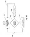
また、電解質を有するコアを有するエネルギ蓄積デバイスを充電するための方法も提供される。この方法は:入力と、電解質及びコアの両端のキャパシタンスの特質と、入力に結合されたエネルギ蓄積デバイスの内部電極間に電界エネルギを蓄積することができる、入力間の内部表面キャパシタンスの特質と、を有するエネルギ蓄積デバイスを提供すること;入力の1つに対し、エネルギ蓄積デバイスの内部表面キャパシタンスを効果的に短絡させるのに充分な周波数で提供された入力電圧と接地入力とのスイッチングを行って、熱を生成するとともに電解質の温度を上昇させること;電解質の温度に相関付けられた測定値を周期的に取得することであって、電解質の温度が、エネルギ蓄積デバイスの充電効率を少なくとも低減すると考えられる低い温度閾値を下回っていることが測定値により示されると、スイッチングが始められ、電解質の温度が、エネルギ蓄積デバイスの充電効率を高めるのに充分であると考えられる高い温度閾値を上回っていることが測定値により示されると、スイッチングが中止され、低い温度閾値は、高い温度閾値よりも低い温度である、電解質の温度に相関する測定値を周期的に取得すること;並びに、電解質の温度が高い温度閾値を上回っていることが測定値により示されている間に、入力電圧を1つの入力に提供してエネルギ蓄積デバイスを充電すること;を含む。Also provided is a method for charging an energy storage device having a core with an electrolyte. The method includes: providing an energy storage device having an input, a capacitance characteristic across the electrolyte and the core, and an internal surface capacitance characteristic between the inputs capable of storing electric field energy between internal electrodes of the energy storage device coupled to the input; switching between an input voltage provided to one of the inputs at a frequency sufficient to effectively short the internal surface capacitance of the energy storage device and a ground input to generate heat and increase the temperature of the electrolyte; periodically obtaining measurements correlated to the electrolyte temperature, the switching being initiated when the measurements indicate that the electrolyte temperature is below a low temperature threshold believed to at least reduce the charging efficiency of the energy storage device and the switching being discontinued when the measurements indicate that the electrolyte temperature is above a high temperature threshold believed to be sufficient to increase the charging efficiency of the energy storage device, the low temperature threshold being a temperature lower than the high temperature threshold; and providing an input voltage to one input to charge the energy storage device while the measurements indicate that the electrolyte temperature is above the high temperature threshold.
電池コア、主に電解質、を直接的に加熱する高周波電流の印加により、摂氏-60度もの低い温度、及び、なお低い温度、において、現在利用可能な電池タイプに加えて超コンデンサのほとんど全ての使用が可能になる。電池を経由する高周波電流流れは、電解質内のイオンの、対応する高周波振動運動を生じ、このことは熱を生成し、それによって電解質及び電池コアの温度を上げる。典型的に、印加される電流周波数は、電池のタイプ及び化学的性質に依存して、数百Hzから数MHzの範囲に及び得る。電池及び超コンデンサのあらゆる損傷を防止するために、電池及び超コンデンサに通される高周波電流は、対称性を有すること、即ち、正味DC成分を有さないか又は有する正味DC成分が無視できるほど小さいこと、が必須である。The application of high frequency current to directly heat the battery core, primarily the electrolyte, enables the use of almost all currently available battery types as well as supercapacitors at temperatures as low as -60 degrees Celsius and even lower. High frequency current flow through the battery creates a corresponding high frequency oscillatory motion of ions in the electrolyte, which generates heat, thereby raising the temperature of the electrolyte and battery core. Typically, the applied current frequency can range from a few hundred Hz to several MHz, depending on the battery type and chemistry. To prevent any damage to the battery and supercapacitor, it is essential that the high frequency current passed through the battery and supercapacitor is symmetrical, i.e., has no net DC component or has a negligible net DC component.
よって、それらの回路実装の方法及び例であって、所望される高周波電流を、DC成分を有さないか又は有するDC成分が無視できるほど小さい状態で、高周波電流の対称性を自動的に保ったまま、電池又は超コンデンサに通す、低い温度用の前述の直接的電池及び超コンデンサ加熱デバイスを構築するために使用される、方法及び例について記載する。Thus, methods and examples of those circuit implementations are described that are used to build the aforementioned direct battery and supercapacitor heating devices for low temperatures that pass the desired high frequency current through the battery or supercapacitor with no or negligible DC component and automatically maintains the symmetry of the high frequency current.
また、環境温度が、電池及び超コンデンサが自身のピーク性能レベルで動作することが可能な温度を下回る間に、電池及び超コンデンサをこのような温度に保つために使用することが可能な、簡素であって非常に効率的なデバイスを有することも、非常に望ましい。例えば、極めて寒冷な環境において、当初、車両の電池は、充電され得るように、又は、車両が動作可能になり得るように、外部から提供された電力によって加熱され得る。しかしながら、車両が走行を開始すると、外部電力はもはや利用可能ではなくなり、電池は、自身の最大限動作可能な性能レベルを下回って冷え込む恐れがあり、ほぼ動作不可能にさえもなる恐れがある。このような条件において、車両電池がピーク性能レベルにおいて又はその付近において動作可能に保たれるように、車両電池をその自身の電力から必要に応じて加熱すること(自己加熱)の可能な、極めて効率的なデバイスを提供することが、非常に望ましい。It is also highly desirable to have a simple and highly efficient device that can be used to keep the battery and supercapacitor at a temperature at which they can operate at their peak performance levels while the environmental temperature is below such a temperature. For example, in a very cold environment, the vehicle's battery may initially be heated by externally provided power so that it can be charged or the vehicle can become operational. However, once the vehicle starts moving, the external power is no longer available and the battery may cool below its maximum operable performance level or may even become nearly inoperable. In such conditions, it is highly desirable to provide a highly efficient device that can heat the vehicle battery as needed from its own power (self-heating) so that the vehicle battery remains operable at or near its peak performance level.
多数の他のシステムが、やはり、このような自己加熱能力を使用して、低い温度において自身を最大限動作可能に保ち得ることが、当業者に認識される。Those skilled in the art will recognize that numerous other systems may also use such self-heating capabilities to keep themselves maximally operable at low temperatures.
よって、電池及び超コンデンサ用の、非常に効率的であって簡素な自己加熱デバイスを構築するために使用される、それらの回路実装の方法及び例について、記載する。Thus, methods and examples of their circuit implementation are described that can be used to build highly efficient and simple self-heating devices for batteries and supercapacitors.
本発明の装置の、これらの及び他の特徴、態様、及び利点は、以下の説明、付随の特許請求の範囲、及び、添付の図面に関して、より良好に理解されるであろう。These and other features, aspects, and advantages of the device of the present invention will become better understood with regard to the following description, the appended claims, and the accompanying drawings.
[詳細な説明]
現在利用可能な超コンデンサのタイプ及び設計の全ては、内部抵抗及び内部インダクタンスを呈示しており、これらは、直列であるものとしてモデル化することができる。超コンデンサの内部抵抗及び内部インダクタンスの両方は、比較的低い。超コンデンサのインダクタンスは、巻回型超コンデンサの場合、構築に関して平坦型及び積層型のものと比較すると有意に高い。漏れ電流は、コンデンサと並列の別個の抵抗器により表され得る。概して、超コンデンサの抵抗は、短期動作において無視され得る。超コンデンサのインダクタンスもまた、低周波動作について無視することができる。 Detailed Description
All currently available supercapacitor types and designs exhibit an internal resistance and an internal inductance, which can be modeled as being in series. Both the internal resistance and the internal inductance of a supercapacitor are relatively low. The inductance of a supercapacitor is significantly higher for wound supercapacitors compared to flat and stacked types of construction. The leakage current can be represented by a separate resistor in parallel with the capacitor. In general, the resistance of a supercapacitor can be neglected in short-term operation. The inductance of a supercapacitor can also be neglected for low-frequency operation.
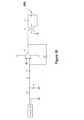
図1の概略図においては、超コンデンサ20の簡素化されたモデルが、集中コンデンサコア21と共に示されており、集中コンデンサコア21内では、前述の等価内部抵抗及び等価内部インダクタンスが、超コンデンサキャパシタンスCに接続された2つの対の直列の抵抗器及びインダクタとして示されている。図1において、直列の抵抗器及びインダクタの対は、抵抗R1及びR2と、インダクタンスL1及びL2と、により示されている。ほとんどの超コンデンサにおいて、抵抗器R1及びR2の抵抗は、極めて低い。本モデルにおいて、集中直列の抵抗器及びインダクタの対は、一方端において超コンデンサキャパシタンスCに接続されており、他方端において超コンデンサ端子22に接続されている。図1において、超コンデンサの内部抵抗は、漏れの原因であり、集中抵抗器R3としてモデル化されている。図1では、簡潔にするために、また、この簡素化が、説明されるべき、超コンデンサを充電及び放電するための方法及び装置に影響を及ぼさないことから、超コンデンサの電気的モデルは、図1において示されているようなものであると考える。In the schematic diagram of FIG. 1, a simplified model of a supercapacitor 20 is shown with a lumped capacitor core 21 in which the aforementioned equivalent internal resistance and equivalent internal inductance are shown as two pairs of series resistors and inductors connected to the supercapacitor capacitance C. In FIG. 1, the series resistor and inductor pairs are shown by resistances R1 and R2 and inductances L1 and L2. In most supercapacitors, the resistance of resistors R1 and R2 is very low. In this model, the lumped series resistor and inductor pair is connected at one end to the supercapacitor capacitance C and at the other end to the supercapacitor terminal 22. In FIG. 1, the internal resistance of the supercapacitor is the source of leakage and is modeled as a lumped resistor R3. In FIG. 1, for the sake of simplicity and because this simplification does not affect the method and apparatus for charging and discharging a supercapacitor to be described, the electrical model of the supercapacitor is considered to be as shown in FIG. 1.
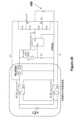
図2、図3、及び図5に概略的に示された第1の実施形態において、内部プロセッサ11aを有する超コンデンサ充電器ユニット11はまず、ステップS1a又はS1bにおいて、超コンデンサコアの内部温度を取得する。このようなプロセッサは、PLC又はCPUといった、ハードウェア、構成要素を備えており、ソフトウェアと、このようなソフトウェアを格納するとともに、以下に記載された方法において使用される予め定められた値といったデータも格納するメモリと、を含むことができる。軍需品が周囲温度において格納されている軍需品といった用途において、超コンデンサコア温度は、ステップS1aにおいて周囲温度を測定することと、周囲温度を超コンデンサコア温度と同一視するといった、周囲温度の何らかの関数を使用して、超コンデンサコアの内部温度を概算することと、によって取得され得る。代替的に、超コンデンサコア温度は、内部センサ12(例として、当該技術で公知の、熱電対ベースのセンサ又は他の温度測定センサ)により直接的に測定することができ、測定された温度信号は、センサコンデンサ端子14に接続された配線13を介してプロセッサ11aに提供される。センサ12は、プロセッサ11aにより使用されて、超コンデンサがその正規のレートでの充電が可能であるかが判定され、或いは、コア温度が大変低いため、超コンデンサ電解質が固体になっており、又は固体に極めて近くなっており、それによって電解質内のイオン輸送を阻害又は妨害しているか、及び、超コンデンサの、その正規の(液体電解質状態の)レートでの迅速な充電を妨害しているか、が判定される。さらにまた別の代替例として、温度センサは、超コンデンサの外部表面上に配置することができ、取得された温度は、外部表面温度を超コンデンサコア温度と同一視するといった、外部表面温度の何らかの関数を使用して、超コンデンサコアの内部温度を概算するために使用される。In a first embodiment, as shown diagrammatically in FIG. 2, FIG. 3, and FIG. 5, a supercapacitor charger unit 11 having an internal processor 11a first obtains the internal temperature of the supercapacitor core in step S1a or S1b. Such a processor may include hardware components, such as a PLC or CPU, and may include software and a memory for storing such software and also storing data, such as predetermined values, used in the methods described below. In applications such as munitions where the munitions are stored at ambient temperature, the supercapacitor core temperature may be obtained by measuring the ambient temperature in step S1a and approximating the internal temperature of the supercapacitor core using some function of the ambient temperature, such as equating the ambient temperature with the supercapacitor core temperature. Alternatively, the supercapacitor core temperature may be measured directly by an internal sensor 12 (e.g., a thermocouple-based sensor or other temperature measurement sensor known in the art), and the measured temperature signal is provided to the processor 11a via wires 13 connected to the sensor capacitor terminals 14. The sensor 12 is used by the processor 11a to determine whether the supercapacitor is capable of charging at its normal rate, or whether the core temperature is so low that the supercapacitor electrolyte has become solid or very close to being solid, thereby inhibiting or impeding ion transport within the electrolyte and preventing the supercapacitor from rapidly charging at its normal (liquid electrolyte) rate. As yet another alternative, a temperature sensor can be placed on the exterior surface of the supercapacitor, and the acquired temperature is used to estimate the internal temperature of the supercapacitor core using some function of the exterior surface temperature, such as equating the exterior surface temperature with the supercapacitor core temperature.
代替的に、図5に示されるように、超コンデンサコア温度は、仮定に基づいて、例として、ステップS1bにおいて、超コンデンサに充電ユニット11を介して正規の充電電圧(又は任意の適切な初期電圧レベル)を印加することにより、取得され得、ステップS2bにおいて、超コンデンサがその正規のレートで充電されていない、即ち、例えば、測定された充電電流が既知の正規の充電電流レートよりも有意に低い、とプロセッサ11aが判定した場合、プロセッサ11aは、超コンデンサコア温度が極めて低いとともに、超コンデンサコアが、その正規の(液体電解質状態の)レートでの充電が可能な温度を下回っていると、仮定することができる。Alternatively, as shown in FIG. 5, the supercapacitor core temperature may be obtained on an assumption basis, for example, by applying a normal charging voltage (or any suitable initial voltage level) to the supercapacitor via the charging unit 11 in step S1b, and if the processor 11a determines in step S2b that the supercapacitor is not charging at its normal rate, i.e., for example, the measured charging current is significantly lower than the known normal charging current rate, the processor 11a may assume that the supercapacitor core temperature is too low and that the supercapacitor core is below a temperature at which it can be charged at its normal (liquid electrolyte state) rate.
以下においては、上で論じたように、超コンデンサ電解質が固体になるか、又は、そのイオンの比較的自由な輸送を効果的に可能にすることができない、温度レベルを示すために、極めて低い温度が使用される。In the following, extremely low temperatures are used to indicate the temperature levels at which the supercapacitor electrolyte becomes solid or is unable to effectively allow relatively free transport of its ions, as discussed above.
安全性の理由から、当業者に認識されるであろうこととして、充電器ユニット11のプロセッサ11aは、超コンデンサの充電レベルを、充電サイクルの開始前に特定することもできる。加えて、温度センサ12は、先に記載したように、充電レートが低い理由が、実際に、超コンデンサコア電解質温度レベルの低さを理由としていることを保証するために、用いることができる。For safety reasons, as will be appreciated by those skilled in the art, the processor 11a of the charger unit 11 may also determine the charge level of the supercapacitor prior to the start of a charging cycle. In addition, the temperature sensor 12 may be used to ensure that a low charge rate is in fact due to a low supercapacitor core electrolyte temperature level, as described above.
図2の概略図において、充電器ユニット11は、電池による給電といった内部からの給電が行われていることが示されている。しかしながら、多くの用途において、充電器ユニット11は、外部源(図示せず)による給電が可能である。充電ユニット11は、充電器ユニット11の電力源に関係なく、同様に機能する。In the schematic diagram of FIG. 2, the charger unit 11 is shown as being internally powered, such as by a battery. However, in many applications, the charger unit 11 may be powered by an external source (not shown). The charger unit 11 functions similarly regardless of the power source of the charger unit 11.
次に、ステップS2a又はS2bのいずれかにおいて、超コンデンサコア温度が極めて低いこと、及び、極めて低い温度レベルを理由として超コンデンサ(満充電されていないことも特定され得る)の迅速な充電が可能ではないこと、がプロセッサ11aにより一旦特定されると、充電器ユニット11は、ステップS5aにおいて超コンデンサの充電を開始することができる。図2の概略図において、充電器ユニット11は、充電器ユニット11の対応する端子16に超コンデンサ20の端子22を接続しているワイヤ15を介して、超コンデンサ20に接続されていることが示されている。Then, once the processor 11a has determined in either step S2a or S2b that the supercapacitor core temperature is too low and that rapid charging of the supercapacitor (which may also be determined to be not fully charged) is not possible due to the too low temperature level, the charger unit 11 can start charging the supercapacitor in step S5a. In the schematic diagram of FIG. 2, the charger unit 11 is shown connected to the supercapacitor 20 via wires 15 connecting terminals 22 of the supercapacitor 20 to corresponding terminals 16 of the charger unit 11.
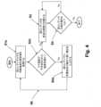
しかしながら、ステップS2a又はS2bにおいて、超コンデンサのコア温度が予め定められた温度未満ではない(例えば、コアが、正常な充電を行うことができる温度を上回る温度である)とプロセッサ11aが判定する(ステップS2a又はS2bにおける判定が否(No)である)場合、充電器ユニットは、ステップS3において超コンデンサを従来の様態で充電し、このことを、超コンデンサがステップS4において満充電されたと判定されるまで、又は、充電がその他の様態で終了されるまで、継続する。However, if in step S2a or S2b the processor 11a determines that the core temperature of the supercapacitor is not below a predetermined temperature (e.g., the core is at a temperature above which normal charging can occur) (the determination in step S2a or S2b is No), the charger unit charges the supercapacitor in a conventional manner in step S3 and continues to do so until the supercapacitor is determined to be fully charged in step S4 or charging is otherwise terminated.
他方で、ステップS2a又はS2bにおける判定が是(Yes)である場合、充電器ユニット11は、超コンデンサの端子22に対し、予め定められた電圧及び電流の1つ以上を入力することができ、電圧及び電流の1つ以上は、エネルギ蓄積デバイスの内部構成要素に熱を生成させる。第1の例示的入力として、充電器ユニット11は、ステップS5aにおいて、超コンデンサに対し、比較的高周波の電圧を印加することができる。高周波電圧は、およそ、最大許容充電超コンデンサ電圧のピーク電圧か、又は、それよりもなお有意に高い電圧、におけるものであり得る。ここで、高周波数とは、超コンデンサのコンデンサが効果的に短絡して、インダクタンスL1及びL2と抵抗R1及びR2とに熱を生成させる、周波数を意味する。次に、プロセッサ11aは、上で論じた方法のいずれかにより、超コンデンサコア温度の取得を、周期的に、例として、いくつかの予め定められた間隔で、継続することができる(図3及び図5において線S6により図示)。超コンデンサコア温度の周期的取得は、上で論じたように、直接的測定値又は仮定により、例として、ステップS1aにおいて温度センサ12を用いて内部温度を測定することにより、又は、ステップS1bにおいて、コンデンサの、正規の充電電圧での充電を試みて、充電電流から充電レートを測定することにより、行うことができる。代替的に、コア(超コンデンサ電解質)温度が超コンデンサの適正な充電についての所望されるレベルに到達するまで、又は、超コンデンサの公称充電レートに到達するまで、のいずれかまで、コア温度を測定するための方法(S1a及びS1b)の両方といった、2つ以上の方法を使用することができる。所望されるレベルへの到達時に、ステップS2a及び/又はS2bにおいて、印加された高周波電圧信号を終了させ、プロセッサ11aは、ステップS3及びS4において、充電ユニット11に、超コンデンサを所望されるレベルまで従来の様態で充電するように指示する。温度レベル及び/又は充電レート測定は、定期的な間隔でといった、必要に応じて、特に、極めて低い周囲温度条件において、繰り返されて、充電のプロセスが超コンデンサ電解質の「再凍結」によって中断しないことを保証し得る。On the other hand, if the determination in step S2a or S2b is Yes, the charger unit 11 can input one or more of a predetermined voltage and current to the terminals 22 of the supercapacitor, which one or more of the voltage and current cause the internal components of the energy storage device to generate heat. As a first exemplary input, the charger unit 11 can apply a relatively high frequency voltage to the supercapacitor in step S5a. The high frequency voltage can be at about the peak voltage of the maximum allowable charging supercapacitor voltage or even a voltage significantly higher than that. Here, high frequency means a frequency at which the capacitor of the supercapacitor effectively shorts out, causing the inductances L1 and L2 and the resistors R1 and R2 to generate heat. The processor 11a can then continue to obtain the supercapacitor core temperature periodically, for example at some predetermined intervals, by any of the methods discussed above (illustrated by line S6 in Figures 3 and 5). The periodic acquisition of the supercapacitor core temperature can be done by direct measurement or assumption, as discussed above, for example by measuring the internal temperature with the temperature sensor 12 in step S1a, or by attempting to charge the capacitor at the normal charging voltage and measuring the charging rate from the charging current in step S1b. Alternatively, more than one method can be used, such as both methods for measuring the core temperature (S1a and S1b), until the core (supercapacitor electrolyte) temperature reaches either a desired level for proper charging of the supercapacitor or until the nominal charging rate of the supercapacitor is reached. Upon reaching the desired level, the applied high frequency voltage signal is terminated in steps S2a and/or S2b, and the processor 11a instructs the charging unit 11 to charge the supercapacitor to the desired level in a conventional manner in steps S3 and S4. Temperature level and/or charge rate measurements may be repeated as necessary, such as at regular intervals, especially in extremely low ambient temperature conditions, to ensure that the charging process is not interrupted by "refrozen" supercapacitor electrolyte.
続いて、図2の概略図と、同様のステップに対し、それぞれ図3及び図5に例示されたものと同様に番号を付けた図4及び図6のフロー図と、を使用して、代替的一実施形態について説明する。代替的実施形態では、ステップS2a又はS2bにおいて、前述の技法のいずれか1つ又は組合せを使用して、超コンデンサ20(満充電されていない)のコア12が極めて低い温度にあると一旦判定されると、プロセッサ11aは、ステップS5bにおいて、充電ユニット11に対し、超コンデンサ端子22と、前述の2つの対の直列接続された抵抗器及びインダクタと、を経由して、等価内部抵抗R3に定電流を通すことにより、コア12を加熱するように指示する。電流は、充電ユニット11により、配線15を経由して生成される。概して、及び、超コンデンサ20のタイプ及び設計と、その充電状態及び電解質温度と、に依存して、電流は、超コンデンサの電圧定格よりも有意に高い電圧で印加され得る。このことは通常可能であるが、その理由は、充電レベルが低いコンデンサの、凍結した電解質が、有意により高い電圧に耐えることができるためである。超コンデンサの定格電圧を上回る加熱電圧を使用するとき、プロセッサ11aは、S6において、超コンデンサのコア温度及び充電状態を定期的にモニタリングして、超コンデンサの充電がその公称レートで又はその付近において開始されるのに伴って加熱電圧を適正に下げる、ことが可能である。An alternative embodiment is now described using the schematic diagram of FIG. 2 and the flow diagrams of FIG. 4 and FIG. 6, in which similar steps are numbered in the same way as those illustrated in FIG. 3 and FIG. 5, respectively. In the alternative embodiment, once it is determined in step S2a or S2b that the core 12 of the supercapacitor 20 (not fully charged) is at a very low temperature using any one or combination of the techniques described above, the processor 11a instructs the charging unit 11 in step S5b to heat the core 12 by passing a constant current through the equivalent internal resistance R3 via the supercapacitor terminals 22 and the two pairs of series-connected resistors and inductors described above. The current is generated by the charging unit 11 via the wiring 15. In general, and depending on the type and design of the supercapacitor 20 and its state of charge and electrolyte temperature, the current can be applied at a voltage significantly higher than the voltage rating of the supercapacitor. This is usually possible because the frozen electrolyte of a capacitor with a low charge level can withstand a significantly higher voltage. When using a heating voltage above the rated voltage of the supercapacitor, the processor 11a can periodically monitor the core temperature and charge state of the supercapacitor in S6 and reduce the heating voltage appropriately as charging of the supercapacitor begins at or near its nominal rate.
概して、ほとんどの超コンデンサの極めて高い内部抵抗レベルR3を理由として、図3及び図5に例示される、超コンデンサの等価インダクタンスL1及びL2を介して超コンデンサコアに熱を提供する方法は、より効果的であり得る。図3及び図5に例示されるこのような方法は、より安全でもあり得るが、その理由は、高周波電流が、超コンデンサの定格電圧において、又は、それをなお上回る電圧において、印加され得るためである。しかしながら、当業者に認識されるであろうこととして、このケースにおけるインダクタコアが、実質上、導電性の超コンデンサ電解質であることから、多くの超コンデンサ内で生成され得る熱の量は比較的少ないことがあり得る。In general, due to the extremely high internal resistance level R3 of most supercapacitors, the method of providing heat to the supercapacitor core via the equivalent inductances L1 and L2 of the supercapacitor, as illustrated in Figures 3 and 5, may be more effective. Such a method, as illustrated in Figures 3 and 5, may also be safer, since high frequency currents may be applied at or even above the rated voltage of the supercapacitor. However, as will be appreciated by those skilled in the art, the amount of heat that may be generated in many supercapacitors may be relatively small, since the inductor core in this case is essentially the conductive supercapacitor electrolyte.
図1に示される集中モデルにおいて、超コンデンサ端子に定電圧を印加することにより、1秒当たりに生成される前述の熱(P)は、
上の方程式から視認できるように、漏れ抵抗R3が極めて大きいことから、超コンデンサに印加することが可能な比較的低い電圧(例えば、2.7ボルトという定格電圧を用いる)について、1秒当たりに生成することのできる熱の量は、極めて少ない。例えば、定格電圧が2.7Vであり、直列抵抗がR1+R2=50mΩであり、漏れ抵抗がR3=10kΩである、典型的な100F超コンデンサについて、上の方程式(1)によると、
別の代替的実施形態では、図1に概略的に示されたものといった典型的な超コンデンサ20のコア21内における上の熱生成レートを有意に上げるために、これまでに記載した定電圧の印加の代わりに、以下の方法を使用することができる。図7に示されるこの方法では、これまでに記載したように、ステップS1c及びS2cにおいて、電池が完全に充電されておらず、且つ、電池コアが極めて低い温度にある、と充電器ユニット11が一旦判定すると、充電器ユニット11は、ステップS5cにおいて、高周波数fにおいてピーク電圧がVpである交流電流(AC)を端子に印加する。集中回路素子(図1及び図2に示されるように、抵抗器R1、R2、及び、R3と、インダクタL1及びL2と、から成る)の挙動は、目下、上の方程式(1)により示されるものとは極めて異なっている。高周波数fにおいて、コンデンサCは、極めて低いインピーダンスを提供し、自身と並列である漏れ抵抗器R3を効果的に短絡させる。結果として、印加した電流に対する全抵抗は極めて小さくなるが、その理由は、抵抗R1及びR2が極めて小さいためである。結果として、1秒当たりに生成される総熱は、極めて大きくなり、したがって、極めて冷たい超コンデンサコア電解質を、超コンデンサの自身の公称充電レートでの又はその付近での充電が可能な温度まで、極めて迅速に加熱することができる。注記されることとして、このような極めて高い周波数において、インダクタL1及びL2はやはり、高いインピーダンスを提供するが、超コンデンサ環境においては通常、低い抵抗R1及びR2により生成されるものよりも有意に少ない熱をもたらす。1秒当たりに生成される熱(出力P)が、下の方程式(2)により、概算によって与えられる。
典型的な総インダクタンスがL1+L2=0.06μH、及び、R1+R2=50mΩであり、漏れ抵抗がR3=10Ωである前述の100F超コンデンサについて、印加したAC電圧が、周波数f=1,000HzでVp=1Vである場合、1秒当たりに生成される熱は9.3Wに到達することが可能である。注記されることとして、上の計算は概算であって、極めて低い温度における、高周波電圧が印加された状態の、超コンデンサキャパシタンスの変化を考慮していない。 For the aforementioned 100 F supercapacitor with typical total inductance L1+L2=0.06 μH and R1+R2=50 mΩ, leakage resistance R3=10Ω, if the applied AC voltage isVp =1 V at frequency f=1,000 Hz, the heat generated per second can reach 9.3 W. It is noted that the above calculation is approximate and does not take into account the change in supercapacitor capacitance at very low temperatures and with high frequency voltage applied.
当業者に認識されるであろうこととして、充電器ユニット11は、記載された超コンデンサ加熱プロセスに加えて超コンデンサの安全な充電のために、コア温度の測定と、示された電流入力及び電圧入力の提供と、を行うため、プロセッサ11aだけではなく、任意の電子機器及び論理回路素子をも必要とする。これらの技術は、実際面で広く使用されており、当該技術で周知であると考えられている。As will be appreciated by those skilled in the art, the charger unit 11 requires not only the processor 11a but also optional electronics and logic circuitry to measure the core temperature and provide the indicated current and voltage inputs for safe charging of the supercapacitor in addition to the described supercapacitor heating process. These techniques are widely used in practice and are considered well known in the art.
上の実施形態において、超コンデンサのインダクタンス又は内部抵抗は、超コンデンサコア(主にその電解質)を、電解質イオンに超コンデンサの迅速な充電を可能にするだけの十分な移動度が提供される温度まで温めるために、記載された充電ユニットにより使用される。超コンデンサは、直列抵抗及びインダクタンスから成り、漏れ電流は、図1において、コンデンサと並列の抵抗器により表されている。直列抵抗(図1においてR1及びR2)は、数ミリオームから数十ミリオームの範囲に及ぶ。インダクタンス(図1においてL1及びL2)は、構造に依存しており、低周波動作については無視することができる。漏れ抵抗もまた、短期動作については無視することができる。超コンデンサ内の電解質は、2つの電極間に導電性接続を形成しており、当該導電性接続は、超コンデンサを、電解質が第2の電極(カソード)である電解コンデンサから区別している。超コンデンサ電極は概して、導電性の金属集電体に適用されているとともに、導電性の金属集電体に電気的に接続されている、薄いコーティングである。電極は、良好な導電性、高温安定性、長期の化学安定性、高耐食性、並びに、単位体積及び質量当たりの高表面積、を有していなければならない。他の要件には、環境適合性及び低コストが含まれる。In the above embodiment, the inductance or internal resistance of the supercapacitor is used by the described charging unit to warm the supercapacitor core (mainly its electrolyte) to a temperature that provides sufficient mobility to the electrolyte ions to allow rapid charging of the supercapacitor. A supercapacitor consists of a series resistance and an inductance, and leakage current is represented in FIG. 1 by a resistor in parallel with the capacitor. The series resistance (R1 and R2 in FIG. 1) ranges from a few milliohms to tens of milliohms. The inductance (L1 and L2 in FIG. 1) depends on the construction and can be neglected for low frequency operation. The leakage resistance can also be neglected for short term operation. The electrolyte in a supercapacitor forms a conductive connection between the two electrodes, which distinguishes the supercapacitor from an electrolytic capacitor, where the electrolyte is the second electrode (cathode). A supercapacitor electrode is generally a thin coating that is applied to and electrically connected to a conductive metal current collector. The electrodes must have good electrical conductivity, high temperature stability, long-term chemical stability, high corrosion resistance, and high surface area per unit volume and mass. Other requirements include environmental compatibility and low cost.
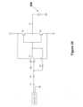
続いて図8を参照すると、別の実施形態は、超電導体及びその電極のタイプ及び設計に関係なく、超コンデンサ電極表面に追加された追加的な抵抗素子及び/又は誘導素子に関するか、或いはさもなければ、超コンデンサコアの全体にわたってこのような抵抗素子及び/又は誘導素子を分散させることに関する。同様に、このような追加的な抵抗素子及び/又は誘導素子は、リチウムイオン電池といった再充電可能電池にも追加することができる。これらの追加された抵抗素子及び/又は誘導素子は、それらの、エネルギ蓄積デバイスの動作への干渉を防止するために、誘電材料により電気的に絶縁することができる。追加された抵抗素子R4及び/又は誘導素子L3は、コア全体にわたって、且つ、その電解質材料のできるだけ付近に、分散させることができる。次に、これまでに記載したように、コア温度が低いと判定されると、追加された抵抗に電流を通すことにより、熱を生成して電解質の温度を上げ、それにより、コア温度が何らかの予め定められた温度又は充電能力よりも上に一旦上昇したときに、その公称レートにおける充電を可能にする。誘導素子が追加されると、電解質の加熱のために、十分に高い周波数の交流電流を使用することができ、それによって極めて低い温度における迅速な充電のプロセスを容易にする。このような超コンデンサ20aを用いる場合、コア加熱に必要とされる電気的入力を、充電器ユニットからの独立配線13aを経由して入力するために、追加的な端子14aを設けることができ、又は、1つのセットの端子22のみを使用して、超コンデンサ20aの充電と、コア加熱用の追加的なインダクタL3及び抵抗器R4への入力と、の両方を行うために、電子論理を設けることができる。Continuing with reference to FIG. 8, another embodiment relates to additional resistive and/or inductive elements added to the supercapacitor electrode surface, regardless of the type and design of the superconductor and its electrodes, or otherwise distributing such resistive and/or inductive elements throughout the supercapacitor core. Similarly, such additional resistive and/or inductive elements can also be added to rechargeable batteries, such as lithium-ion batteries. These added resistive and/or inductive elements can be electrically insulated by a dielectric material to prevent them from interfering with the operation of the energy storage device. The added resistive element R4 and/or inductive element L3 can be distributed throughout the core and as close as possible to the electrolyte material. Then, as described above, when the core temperature is determined to be low, a current is passed through the added resistance to generate heat and raise the temperature of the electrolyte, thereby allowing charging at its nominal rate once the core temperature rises above some predetermined temperature or charging capacity. When an inductive element is added, a sufficiently high frequency alternating current can be used for heating the electrolyte, thereby facilitating the process of rapid charging at very low temperatures. When using such a supercapacitor 20a, additional terminals 14a can be provided to input the electrical input required for core heating via a separate wire 13a from the charger unit, or electronic logic can be provided to use only one set of terminals 22 to both charge the supercapacitor 20a and input to the additional inductor L3 and resistor R4 for core heating.
図9には、超コンデンサ試験ユニット100のブロック図が示されている。25MHz任意波形発生器といったファンクションジェネレータ102が設けられている。また、電力増幅器104も設けられており、電力増幅器104は、以下に記載されるように、超コンデンサインピーダンスと、必要とされる出力範囲と、を整合させることによって、利用可能な2~30MHz RF電力増幅器を改変することにより、構築することができる。DC電源106が、出力電圧及び出力電流の限界設定を有する調整源によって設けられている。試験負荷又はユーザデバイス108は、高電力抵抗器であり得、この高電力抵抗器は、超コンデンサ内に蓄積された利用可能なエネルギを測定するために使用される。In FIG. 9, a block diagram of the
ファンクションジェネレータの周波数、及び、電力増幅器の電圧振幅は、手動で設定することができる。DAQ及びDSPボードが装備されたホストコンピュータ110が、プロセスを制御する手段であって、データ収集と、オンラインでの解析及びフィードバックと、のための手段、を提供することができる。急速な入力/出力動作及びサンプリング時間に備えるために、DSPボードクロックを使用することができる。設けられたシステムにより、負荷の両端の電圧及び電流と、消費電力と、それにより、負荷インピーダンスと、の連続的測定を可能にすることができる。DC電源106もまた、DSPベースのコントローラ110により制御可能であって、所望される充電プロファイルを達成することができる。試験負荷を使用して、充電された超コンデンサが充電後に提供することが可能なエネルギの量を測定することができる。スイッチ112は、DSPコントローラ110により制御されており、超コンデンサ114を所望される回路素子に接続するために使用することができる。電圧センサ116及び電流センサ118のセットが、自身の値を、DAQを介してDSP A/Dコンバータに報告する。コントローラ110は、ホストコンピュータと通信して、各デバイスのコマンド及びステータスを交換することができる。DSPコントローラ110は、充電パルスを生成することもできる。The frequency of the function generator and the voltage amplitude of the power amplifier can be set manually. A
超コンデンサ試験ユニットは、超コンデンサ負荷に対し、高周波正弦波AC電圧信号を、DCバイアスを伴って又は伴わずに、印加するように設計することができる。AC信号の電圧及び周波数は、手動で又は自動的に制御することができる。負荷の両端の電圧、超コンデンサ負荷を通る電流、及び、それらの位相、が測定される。次に、負荷に印加された電力、及び、負荷のインピーダンス、を計算することができる。The supercapacitor test unit can be designed to apply a high frequency sinusoidal AC voltage signal, with or without DC bias, to a supercapacitor load. The voltage and frequency of the AC signal can be controlled manually or automatically. The voltage across the load, the current through the supercapacitor load, and their phases are measured. The power applied to the load and the impedance of the load can then be calculated.
高周波25MHzファンクションジェネレータ102を、電力増幅器104への入力として使用することができる。電力増幅器104は、既存のRF電力増幅器の入力及び出力のインピーダンスを改変することによって構築することができる。図10に、既存の2~30MHz RF電力増幅器設計の回路図を示す。このデバイスの公称電力出力は、30ワットであり得、これは、超電導体の充電に適切である。A high frequency 25
既存のホストコンピュータには、この目的のために、DAQ及びDSPボードが設けられている。適正なデータ通信と、センサデータの獲得及び処理とを伴ってシステムを稼働させるために、並びに、必要とされる制御信号を生成するために、必要とされるソフトウェアは、コントローラ110によりアクセス可能なメモリ(図示せず)内に格納することができる。The existing host computer is equipped with a DAQ and DSP board for this purpose. The software required to run the system with proper data communication, sensor data acquisition and processing, and to generate the required control signals can be stored in memory (not shown) accessible by the
充電ユニット100は、異なるAC周波数、温度、及び、電圧において、超コンデンサ114のインピーダンスを測定することができる。ファンクションジェネレータ102を使用して、調節可能な電圧信号、例えば最大で25MHzを用いて、正弦波を生成することができる。電力増幅器104は次に、予め定められた(予め設定された)電圧レベルでAC電圧を発生させて超コンデンサに印加する。パルス発生器により制御されているスイッチ112を使用して、AC電圧周波数に依存して、10から100マイクロ秒という調節可能な短い持続時間といった予め定められた時間期間にわたり、超コンデンサ114にAC電圧を印加する。短い持続時間の入力電力により、総入力エネルギが無視できるほど小さいことが保証される。次に、入力電圧及び入力電流の波形が測定されて、超コンデンサのインピーダンスを計算するために使用される。The charging
超電導体充電の試験は、-20℃、-25℃、-35℃、-45℃、-48℃、-54℃、及び、-65℃といった様々な温度で行うことができる。これらの試験は、2.7V、3.2V、4.5V、6V、8V、及び、10Vといった様々なAC電圧振幅も使用することができる。AC電圧周波数範囲は、2MHzから25MHzであり得、試験は、0.5MHz刻みで実施することができる。Tests of superconductor charging can be performed at various temperatures, such as -20°C, -25°C, -35°C, -45°C, -48°C, -54°C, and -65°C. These tests can also use various AC voltage amplitudes, such as 2.7V, 3.2V, 4.5V, 6V, 8V, and 10V. The AC voltage frequency range can be from 2MHz to 25MHz, and tests can be performed in increments of 0.5MHz.
これまでに記載したように、超コンデンサに対する高周波AC電圧の印加は、低い温度における、超コンデンサコア、特にその電解質を、印加されたDC電圧で超コンデンサを充電する前に加熱することが目的である。As previously described, the purpose of applying a high frequency AC voltage to the supercapacitor is to heat the supercapacitor core, and in particular its electrolyte, at a low temperature, prior to charging the supercapacitor with an applied DC voltage.
デバイスを試験する目的は、上記の方法で使用するためのデータベースをビルドするために、どの時点でAC電圧を停止させなければならず、且つ、DC充電を開始すべきであるか、を判定することである。およそ-45℃から48℃を下回る極めて低い温度において、電解質は、ほぼ凍結した固体であり、超コンデンサのインピーダンスは極めて高い。しかしながら、電解質が活性になる(溶融する)のに伴って、超コンデンサの実効キャパシタンスが迅速に増大することにより、インピーダンスの迅速な降下を生じ、それにより、通っている電流のレベルをそれに応じて上げる。試験では、AC電流レベルが測定され、このAC電流レベルが10、25、50、75、及び、100倍上がった後に、AC電圧をオフにスイッチングすることができ、DC充電電圧を超コンデンサに印加することができる。試験では、例えば、充電電流が20mAに降下するまで超コンデンサを3.2Vで充電することができ、この時点で、超コンデンサは満充電されたと考えられる。次に、超コンデンサ内の蓄積エネルギを試験負荷108を経由して放電することにより、利用可能な蓄積エネルギが測定される。The purpose of testing the device is to determine when the AC voltage should be stopped and DC charging should commence in order to build a database for use in the above method. At very low temperatures, below approximately -45°C to 48°C, the electrolyte is almost a frozen solid and the impedance of the supercapacitor is very high. However, as the electrolyte becomes active (melts), the effective capacitance of the supercapacitor increases quickly, causing a rapid drop in impedance, which in turn increases the level of current passing accordingly. In testing, the AC current level is measured and after this AC current level has increased by 10, 25, 50, 75 and 100 times, the AC voltage can be switched off and a DC charging voltage can be applied to the supercapacitor. In testing, for example, the supercapacitor can be charged at 3.2V until the charging current drops to 20mA, at which point the supercapacitor is considered fully charged. The available stored energy in the supercapacitor is then measured by discharging the stored energy in the supercapacitor through a
AC電流及び電圧プロファイル、並びに、DC充電時間、が記録される。試験は、超コンデンサが温度チャンバ120内にある間に実施することができる。試験は、コンデンサが典型的な断熱ジャケットで包まれた状態で、並びに、熱損失に抗って或る特定のレベルの断熱をもたらす筐体内において、及び、あらゆる筐体の外において、のそれぞれにおいて、据え付けられた超コンデンサを模倣するために断熱を伴わない状態で、実施することができる。The AC current and voltage profiles, as well as the DC charging time, are recorded. Testing can be performed while the supercapacitor is in the
試験中に、蓄積エネルギが、期待される利用可能な蓄積エネルギの95%未満である場合に、超コンデンサ114は、損傷を受けていると考えられる。During testing, if the stored energy is less than 95% of the expected available stored energy, the
このような試験を使用して、低い温度において超コンデンサを充電するための上記の方法を最適化して、最小量の時間での満充電を達成することができるとともに、低い温度における超コンデンサの充電用の全体的な時間最適戦略を策定することができる。Using such testing, the above methods for charging supercapacitors at low temperatures can be optimized to achieve full charge in the minimum amount of time, as well as to develop an overall time-optimal strategy for charging supercapacitors at low temperatures.
超コンデンサの予熱、及び、それに続くDC充電のための、AC電圧及び周波数の範囲と、期待される最適AC-DCスイッチング時点と、の特定は、実装用の所望される時間最適戦略を取得するために試験及び微調整されることが可能な、異なる低い温度レベルについて行うことができる。Identification of the range of AC voltages and frequencies and the expected optimal AC-DC switching instants for pre-heating the supercapacitor and subsequent DC charging can be done for different low temperature levels that can be tested and fine-tuned to obtain the desired time-optimal strategy for implementation.
よって、上の試験デバイス及び方法を使用して、様々な低い温度において、様々なサイズ及び構成の超コンデンサを満充電まで充電するのに必要とされる時間に関する統計情報を取得することができる。この、生成された統計情報は、所与の温度でコンデンサを充電するのに必要とされる平均時間と、95%といった或る特定の信頼水準における、その標準偏差と、を含み得る。Thus, using the above testing device and method, statistical information can be obtained regarding the time required to fully charge supercapacitors of various sizes and configurations at various low temperatures. The generated statistical information can include the average time required to charge a capacitor at a given temperature and its standard deviation at a certain confidence level, such as 95%.
当業者に認識されるであろうこととして、低い温度において超コンデンサを充電するための、開示された試験デバイス及び方法は、上記の他の方法(例として、図3~図6における)に対し、並びに/又は、異なるタイプの、通例公知の超コンデンサ、ウルトラコンデンサ、及び、いわゆるハイブリッドコンデンサ等のために、加えて、リチウムイオン電池といった再充電可能電池に対し、適用することができる。As will be appreciated by those skilled in the art, the disclosed test device and method for charging supercapacitors at low temperatures can be applied to other methods described above (e.g., in Figures 3-6) and/or for different types of commonly known supercapacitors, ultracapacitors, and so-called hybrid capacitors, as well as rechargeable batteries, such as lithium-ion batteries.
低い温度において超コンデンサを迅速に充電するための、上の方法及びデバイスを使用して、低い温度におけるリチウムイオン電池及び他の同様の再充電可能電池の充電レートを同様に可能にすること、及び/又は、有意に上げること、も可能である。上で論じたように、低い温度における充電は概して、リチウムイオン電池及び他の同様の再充電可能電池にとって、より一層大きな問題であるが、その理由は、それらの充電レートが、超コンデンサよりもなお高い温度、通常は、摂氏ゼロ度を数度下回る温度においてさえも、低いためである。Using the above methods and devices for rapidly charging supercapacitors at low temperatures, it is also possible to similarly enable and/or significantly increase the charging rate of lithium-ion batteries and other similar rechargeable batteries at low temperatures. As discussed above, charging at low temperatures is generally even more of a problem for lithium-ion batteries and other similar rechargeable batteries because their charging rates are lower even at higher temperatures than supercapacitors, typically even at temperatures a few degrees below zero Celsius.
リチウムイオン電池及び他の同様の再充電可能電池のケースにおいて、充電プロセスは、超コンデンサ用の、これまでに記載した方法と同様に、同様のステップを含んでいる。リチウムイオン電池が充電を必要としており、且つ、そのコアが、充電を阻止/最小化する低い温度にあると判定された後に、電池の電解質及び電極は、図3~図7に関して述べたような同様の方法によって加熱され、当該加熱は、電池の端子に対し、その内部構成要素に熱を生成させる、予め定められた電圧入力及び電流入力の1つ以上を入力することによって、例として、電池のサイズ及び構造に依存して、通常は1~10MHzのオーダの、時としてそれよりも高い、AC高周波電圧を印加することによって、行われる。次に、電池コア、特にその電解質が、所望される予め定められた温度又は充電能力に一旦到達すると、安全で迅速な充電を保証するための周知の電子回路素子及び論理回路素子並びに手続きに従って、従来の様態でDC電圧を使用して電池を充電することができ、所望される予め定められた温度又は充電能力への到達は、上記のように温度センサを用いて直接的に検出され得るか、又は、例として、同じく上記のように、AC電圧及び/若しくはDC電圧を用いた充電レートの検出により、仮定され得る。In the case of lithium-ion and other similar rechargeable batteries, the charging process involves similar steps as the previously described methods for supercapacitors. After it is determined that the lithium-ion battery needs charging and its core is at a low temperature that prevents/minimizes charging, the electrolyte and electrodes of the battery are heated in a similar manner as described with respect to Figures 3-7, by applying to the battery terminals one or more predetermined voltage and current inputs that cause its internal components to generate heat, for example, by applying an AC high frequency voltage, typically on the order of 1-10 MHz, sometimes higher, depending on the size and construction of the battery. The battery can then be charged in a conventional manner using a DC voltage, once the battery core, and particularly its electrolyte, has reached the desired, predetermined temperature or charging capacity, in accordance with well-known electronic and logic circuit elements and procedures to ensure safe and rapid charging, and reaching the desired, predetermined temperature or charging capacity can be detected directly using a temperature sensor as described above, or can be assumed, for example, by detection of the charging rate using an AC voltage and/or a DC voltage, also as described above.
当業者によって認識されるであろうこととして、リチウムイオン電池及び他の同様の再充電可能電池の充電(超コンデンサの充電を含む)における多くのケースにおいて、最適充電時間は、通常、AC電圧からDC電圧へのスイッチング前に、時間の一部において、AC電圧とDC電圧充電とを重複させることによって達成することができる。As will be appreciated by those skilled in the art, in many cases in charging lithium ion and other similar rechargeable batteries (including supercapacitor charging), optimal charging times can usually be achieved by overlapping the AC and DC voltage charging for a portion of the time before switching from the AC voltage to the DC voltage.
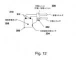
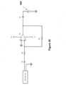
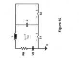
リチウムイオン電池の基本動作は、図11に示される等価(集中)回路素子を用いて、概算によりモデル化され得る。このモデルにおいて、抵抗器Reは、電極及び配線が作製されている導電性材料内で電子が自由に移動することに抗う電気抵抗であると考えられる。等価抵抗器RIは、電池電解質による、リチウムイオンの自由移動に対する(「本質的に粘性の」)抵抗を表す。等価インダクタLIは、その運動状態の変化に対する(「本質的に慣性の」)抵抗を表し、この抵抗は、必要とされる運動の周波数が極度に高くなるまで問題にならない。コンデンサCsは、表面キャパシタンスであり、表面キャパシタンスは、電極間に電界エネルギを蓄積することができ、コンデンサの平行平板と同様に作用する。抵抗器Rc及びコンデンサCcは、電池の電気化学的メカニズムを表しており、電池において、Ccは、電池充電中には化学エネルギとして蓄積されるとともに、電池放電中には再び電気エネルギとして放電されることが可能な、電気エネルギを示すことが意図されており、Rcは、等価抵抗器を示しており、当該抵抗器では、放電電気エネルギの一部が消費され(失われ)て、本質的に熱に変換される。端子A及びBは、リチウムイオン電池の端子を示すことが意図されており、端子C及びDは、回路素子内の他の内部点である。 The basic operation of a lithium-ion battery can be modeled approximately using the equivalent (lumped) circuit elements shown in FIG. 11. In this model, resistor Re is considered to be the electrical resistance that opposes the free movement of electrons in the conductive material of which the electrodes and wiring are made. Equivalent resistor RI represents the resistance ("essentially viscous") to the free movement of lithium ions due to the battery electrolyte. Equivalent inductor LI represents the resistance ("essentially inertial") to changes in its state of motion, which is not an issue until the frequency of the required motion becomes extremely high. Capacitor Cs is a surface capacitance that can store electric field energy between the electrodes, acting similarly to the parallel plates of a capacitor. ResistorRc and capacitorCc represent the electrochemical mechanism of the battery, whereCc is intended to represent the electrical energy that is stored as chemical energy during battery charging and can be discharged again as electrical energy during battery discharge, andRc represents the equivalent resistor where a portion of the discharge electrical energy is consumed (lost) and essentially converted to heat. Terminals A and B are intended to represent the terminals of a lithium-ion battery, and terminals C and D are other internal points within the circuit element.
当業者に認識されるであろうこととして、多くの異なるリチウムイオンタイプ及び設計、並びに、異なる化学組成、が現在利用可能である。やはり当業者に認識されることとして、リチウムイオン電池の他のモデルもまた、開発されてきた。しかしながら、図11の概略図に提示されたモデルは、低い温度においてこのような電池を充電するための、開示された方法及び装置に関する限り、リチウムイオン電池の基本的構成要素を表している。したがって、本明細書に記載された方法及び装置は、単に図11により表された構成を有するものだけではなく、全ての異なる設計構造及び化学的性質を有する、全ての異なるタイプ及び設計のリチウムイオン電池に当てはまる。現在利用可能な、リチウムイオン電池の充電方法及びデバイスが、これらの電池の、摂氏ゼロ度付近でさえある低い温度における充電に使用されることが不可能である理由については、上に簡単に記載しているとともに、既刊文献には存分に記載されており、使用された場合には、電池に損傷を与え、火災の危険さえも生じる、ことが示されている。As will be appreciated by those skilled in the art, many different lithium ion types and designs, as well as different chemical compositions, are currently available. As will also be appreciated by those skilled in the art, other models of lithium ion batteries have also been developed. However, the model presented in the schematic diagram of FIG. 11 represents the basic components of a lithium ion battery as far as the disclosed method and apparatus for charging such batteries at low temperatures is concerned. Thus, the methods and apparatus described herein apply to all different types and designs of lithium ion batteries, having all different design structures and chemistries, not just those having the configuration depicted by FIG. 11. The reasons why currently available methods and devices for charging lithium ion batteries cannot be used to charge these batteries at low temperatures, even near zero degrees Celsius, are briefly described above and are fully described in the published literature, and show that doing so would damage the battery and even pose a fire hazard.
図11に示されるリチウムイオン電池の、近似の等価(集中)回路素子モデルにおいては、電池の3つの構成要素、つまり、RI、Rc、及び、Ccが、温度に対して高感度である。低い温度において、抵抗器RIの抵抗は、リチウムイオンの移動に対する電解質の「粘性」抵抗の増大を理由に増大する。この抵抗の増大は、リチウムイオン電池の充電及び放電中に、より高い損失を生じる。低い温度における充電は、電池の電気化学反応を表す、示された構成要素Rc及びCcに(比較的高い)電流を通し、いわゆるリチウムめっきを結果的に生じることが周知であり、このリチウムメッキは本質的に不可逆性であって、電池充電を妨害し、電池に永続的に損傷を与える。 In the approximate equivalent (lumped) circuit element model of a lithium-ion battery shown in Fig. 11, three components of the battery, namely RI , Rc and Cc , are highly sensitive to temperature. At low temperatures, the resistance of resistor RI increases due to the increased "viscous" resistance of the electrolyte to the movement of lithium ions. This increased resistance results in higher losses during charging and discharging of a lithium-ion battery. It is well known that charging at low temperatures passes (relatively high) currents through the indicated components Rc and Cc , which represent the electrochemical reactions of the battery, resulting in the so-called lithium plating, which is essentially irreversible and disrupts the battery charging and permanently damages the battery.
低い温度においてリチウムイオン電池を充電するための方法の一実施形態は、以下のように説明することができる。図11の回路モデルを考えられたい。十分に高い周波数を有するAC電流が電池に印加される場合、コンデンサCsのインピーダンスが低いことを理由に、コンデンサの両端には、即ち、接合部CとDとの間には、有意な電圧降下が存在せず、回路は、コンデンサCsが短絡しているかのように効果的に挙動する。結果として、印加された高周波AC電流は本質的に抵抗器Re及びRIを通り、Rc及びCc分岐を通って電池の電気化学構成要素に損傷を与えない。Rc及びCc分岐を通る、あらゆる残留電流も、印加した電流の高周波数とゼロDC成分とを理由に、やはり、電池に損傷を与えない。次に、抵抗器Re及びRIを通る高周波AC電流は、電池コアを加熱し、それによってその温度を上げる。高周波AC電流が十分に長い時間期間にわたって印加される場合、電池コア温度は、通例使用されるDC充電方法を使用した充電を安全にするのに十分な程度、上昇する。 One embodiment of a method for charging a lithium-ion battery at low temperatures can be described as follows. Consider the circuit model of FIG. 11. When an AC current with a sufficiently high frequency is applied to the battery, due to the low impedance of the capacitorCs , there is no significant voltage drop across the capacitor, i.e., between junctions C and D, and the circuit effectively behaves as if the capacitorCs is shorted. As a result, the applied high frequency AC current essentially passes through resistors Re and RI and does not damage the electrochemical components of the battery through the Rc and Cc branches. Any residual current through the Rc and Cc branches also does not damage the battery due to the high frequency and zero DC component of the applied current. The high frequency AC current through resistors Re and RI then heats the battery core, thereby increasing its temperature. If the high frequency AC current is applied for a sufficiently long period of time, the battery core temperature rises enough to make charging safe using commonly used DC charging methods.
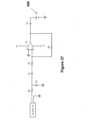
さらに、AC電流の、要求される周波数が高くなると、インダクタンスLIは、充電デバイスからの高AC電圧電位要件を示す。換言すると、充電デバイスのAC電圧制限が存在するものの、インダクタンスLIは、周波数が十分に高くなり、それによって自身の両端において全ての電圧電位降下が減少すると、優位に立つようになる。エネルギの一部が、依然としてこのインダクタからの熱に変えられているとはいえ、それは、RIからのものよりもはるかに少ない。したがって、高周波AC電流は、インダクタンスLIを考慮して選択することができる。 Furthermore, as the required frequency of the AC current becomes higher, the inductance LI represents a high AC voltage potential requirement from the charging device. In other words, although there are AC voltage limitations of the charging device, the inductance LI becomes dominant once the frequency becomes high enough, thereby reducing the total voltage potential drop across it. Although some energy is still converted to heat from this inductor, it is much less than that from RI. Thus, high frequency AC currents can be selected with the inductance LI in mind.
前述の高周波AC電流を提供して、電池コア温度を安全充電温度まで上昇させるように設計されたデバイスでは、電池コアの温度ステータスを周期的に査定して、安全充電温度レベルに到達したかを判定するために、対策を講じることができる。In devices designed to provide the aforementioned high frequency AC current to raise the battery core temperature to a safe charging temperature, measures can be taken to periodically assess the temperature status of the battery core to determine if a safe charging temperature level has been reached.
低い温度においてリチウムイオン電池を充電するための方法及び装置において、図12の超コンデンサに関して上で論じたものと同様に、温度センサの使用が可能であるが、温度センサの必要なしに電池コア温度を査定するために、2つの基本的な方法が使用され得る(よって、このような方法において又はこのような装置と共に使用するための、リチウムイオン電池の特別な構成を必要としない)。1つの方法では、前述の高周波AC電流が電池に印加されるのに伴い、電池インピーダンスが定期的に測定される。抵抗器RIの抵抗が低い温度において高いことから、電池インピーダンスのレベルは、電池コア温度が低いのか、又は、充電にほぼ安全な温度であるのか、を示す。この方法を使用すると、電池のインピーダンスを、使用する充電器のために事前に測定して、電池コアの安全充電温度にいつ到達したのかを判定することができる。 In a method and apparatus for charging a lithium-ion battery at low temperatures, the use of a temperature sensor is possible, similar to that discussed above with respect to the supercapacitor of FIG. 12, but two basic methods can be used to assess the battery core temperature without the need for a temperature sensor (and thus without requiring special configuration of the lithium-ion battery for use in such a method or with such an apparatus). In one method, the battery impedance is measured periodically as the high frequency AC current described above is applied to the battery. Since the resistance of resistor RI is high at low temperatures, the level of battery impedance indicates whether the battery core temperature is low or near a safe temperature for charging. Using this method, the battery impedance can be measured in advance for the charger to be used to determine when the safe charging temperature of the battery core has been reached.
前述の高周波AC電流を印加しながら、電池コア温度が安全充電温度レベルに到達したのかを判定するための第2の方法は、以下の通りである。この方法では、高周波AC電流が周期的に遮断され、極めて短い持続時間にわたり、抵抗負荷を経由して電池から電流が放電される。電池コアが依然として冷たい場合、負荷の両端の電圧は低い。A second method for determining if the battery core temperature has reached a safe charging temperature level while applying the high frequency AC current described above is as follows. In this method, the high frequency AC current is periodically interrupted and current is discharged from the battery through a resistive load for very short durations. If the battery core is still cold, the voltage across the load will be low.
当業者に認識されるであろうこととして、上記の方法の両方を、電池充電ユニットに容易に組み込むことができる。実際に、前述の高周波AC電流の印加に必要とされる電気回路素子及び電子回路素子に加え、安全な充電のためにリチウムイオン電池コア温度を査定する上の方法の一方及び/又は両方は、1つの単一の充電ユニット内に容易に組み込まれ得る。このようなユニットは、電池コア温度が安全な充電レベルまで一旦上昇すると、通例知られている方法を使用して電池を充電することもできる。As will be appreciated by those skilled in the art, both of the above methods can be readily incorporated into a battery charging unit. Indeed, one and/or both of the above methods of assessing lithium-ion battery core temperature for safe charging, in addition to the electrical and electronic circuit elements required for the application of the aforementioned high frequency AC current, can be readily incorporated into one single charging unit. Such a unit can also charge the battery using commonly known methods once the battery core temperature has been raised to a safe charging level.
さらに、DC充電が一旦開始すると、充電ユニットは、電池コア温度を周期的に査定するようにプログラミングされ得、温度が安全ではない(低い)温度に近付いていることを検出する場合、高周波AC電流が投入され、DC充電電流が遮断される。代替的に、高周波AC電流は、充電DC電流上に重畳され得る。Furthermore, once DC charging has commenced, the charging unit can be programmed to periodically assess the battery core temperature and, if it detects that the temperature is approaching an unsafe (low) temperature, high frequency AC current is injected and the DC charging current is shut off. Alternatively, high frequency AC current can be superimposed on the charging DC current.
リチウムイオン電池には、その温度を測定するために、いくつかの現在利用可能なリチウムイオン電池において使用されているものといった温度センサも設けられ得る。すると、温度センサ入力は、前述の方法の一方又は両方に加えてのものであり得るのだが、電池の安全充電温度を特定するために使用され得る。The lithium ion battery may also be provided with a temperature sensor, such as those used in some currently available lithium ion batteries, to measure its temperature. The temperature sensor input may then be used to determine a safe charging temperature for the battery, which may be in addition to one or both of the methods described above.
前述の高周波AC電流は、低い温度においてリチウムイオン電池コア温度を上げて、より高い放電レートを達成する、ためにも使用され得る。このようにして、本方法は、低い温度においてリチウムイオン電池を充電する手段を提供し、加えて、低い温度において、リチウムイオン電池の性能を高める、即ち、それらの放電レートを上げる、手段を提供する。The aforementioned high frequency AC current can also be used to raise the lithium ion battery core temperature at low temperatures to achieve higher discharge rates. In this way, the method provides a means to charge lithium ion batteries at low temperatures and in addition provides a means to enhance the performance of lithium ion batteries, i.e., increase their discharge rates, at low temperatures.
図12には、低い温度において、電解質電池コア208を有するリチウムイオン電池206を充電及び/又は放電するための新規の本方法を使用する装置のブロック図が示されている。充電/放電ユニット200(一括して本明細書では「充電ユニット」と称する)には、前述の高周波AC電流及び充電DC電流を、両方が電圧制御を伴った状態で提供する、電気回路素子及び電子回路素子が設けられており、これまでに記載したように、電池コア温度を測定することと、コア温度が電池安全充電温度を下回っている場合にコア温度を上げることと、電池コア温度が当該安全充電温度を上回ると充電することと、を行うプロセスを制御するための、マイクロプロセッサ又はCPUといったプロセッサ202を含むことができる。充電ユニット200は、電池206の端子210に接続するための配線を有している。このような方法を実行するためのプロセスステップは、プロセッサ202によりアクセス可能なメモリデバイス上のソフトウェアとして格納することができる。充電ユニット200は、電池インピーダンスに基づいて、前述の方法の一方又は両方を使用することにより、及び/或いは、代替的に、外部又は内部の電池温度センサ源204から、温度を周期的にチェックして、充電プロセスを適正に誘導する。12 shows a block diagram of an apparatus using the novel method for charging and/or discharging a
代替的に、図12の充電ユニットは、充電及び放電制御ユニットとして機能することがあり得、電池コア温度が、前述の、充電についての安全充電温度を下回っていると、電池に対して適切な高周波AC電流を印加することによって電池コア温度を上げることがあり得、この適切な高周波AC電流の後に、DC充電電流が続くことになる。電池温度がその性能、即ち、その所望される放電レート、を有意に低下させるほど十分に低い場合、充電ユニット200はやはり、電池206に対して高周波AC電流を印加して、そのコア温度を上げて、その放電レートを上げる。Alternatively, the charging unit of FIG. 12 may function as a charge and discharge control unit and may raise the battery core temperature by applying an appropriate high frequency AC current to the battery, followed by a DC charging current, if the battery core temperature is below the aforementioned safe charging temperature for charging. If the battery temperature is low enough to significantly degrade its performance, i.e., its desired discharge rate, the charging
図13のブロック図には、リチウムイオン充電及び放電ユニットの一実施形態300が示されている。ユニット300は、専ら、低い温度においてリチウムイオン電池を充電するために使用することが可能であるものの、低い温度を含む全ての温度における、リチウムイオン電池用充電及び放電ユニットとしての使用が意図されている。The block diagram of FIG. 13 shows one
ここで認識されることとして、リチウム電池充電について、低い温度とは、DC電流(連続電流若しくはパルス電流、又は、当該技術で公知の他の変形例等)が電池への損傷を生じるか、或いは、電池を効果的に充電することができない、電池コア温度を示すことが意図されている。リチウムイオン電池放電プロセスにおいて、低い温度とは、リチウムイオン電池放電レートが、その正常なレートよりも有意に低いときの温度を示すことが意図されている。リチウムイオン電池では、後者の温度は概して、電池の安全な充電用の温度よりも低い。It is recognized that, for lithium battery charging, low temperature is intended to refer to the battery core temperature at which DC current (such as continuous or pulsed current, or other variations known in the art) will cause damage to the battery or will not effectively charge the battery. In the lithium ion battery discharge process, low temperature is intended to refer to the temperature at which the lithium ion battery discharge rate is significantly lower than its normal rate. For lithium ion batteries, the latter temperature is generally lower than the temperature for safe charging of the battery.
ユニット300は、矢印302により概略的に示されるように、外部電源により給電されており、外部電源は、例えば、電気自動車のリチウムイオン電池を充電するために屋外に設けられたコンセントであり得る。これまでに論じたように、内部又は外部の温度センサ303を有すること又は有さないことがあり得る電池301のステータスを、充電されている間に判定するために、マイクロプロセッサベースのコントローラ304(代替的に、本明細書及び図13では「制御ユニット」と称する)が使用され、電池301は、その電池コアが安全充電温度を下回っていると判定されると、AC電流及びDC電流発生器306に対し、矢印AC307により概略的に示される高周波AC電流を出力するように指示し、電池301が充電するのに安全であると、AC電流及びDC電流発生器306に対し、示されたスイッチング素子310を使用して、矢印DC308により概略的に示されるDC電流を出力するように指示する。制御ユニット304は、電池301の内部温度を安全な量だけ上げて、より急速なレートでの電池301の充電を可能にする、ようにプログラミングされ得る(その指示は、ユニット300内に設けられ、且つ、制御ユニット304によりアクセス可能な、メモリ内に格納され得る)。高周波AC電流及びDC電流は、示されたAC電流及びDC電流発生器306により生成され、AC電流及びDC電流発生器306は、ユニット入力電力302から給電されるとともに、矢印312により示されるように、制御ユニット306と直接的に通信している。制御ユニット304は、AC電流及びDC電流スイッチング素子310とも常に通信しており、AC電流又はDC電流の一方又は他方が投入又は遮断される必要があるかを判定することができる。この実施形態では、一時にAC電流又はDC電流の一方のみをオンにすることが可能である。The
図13の実施形態300において、AC電流又はDC電流のいずれかが投入されると、矢印316aにより示されるように、充電電圧、電流、及び、インピーダンスの測定、並びに、充電及び放電の調整ユニット314に電流が通され、充電電圧、電流、及び、インピーダンスの測定、並びに、充電及び放電の調整ユニット314は、制御ユニット304に必要とされる前述の電流、電圧、及び、インピーダンスの測定値を特定して、これまでに記載したような充電プロセスを制御する、ために使用される。充電電圧、電流、及び、インピーダンスの測定、並びに、充電及び放電の調整ユニット314は、制御ユニット304により誘導されるように、充電サイクル中の充電電流及び放電サイクル中の放電電流も調整して、電池301及び充電及び放電ユニット300の適正且つ安全な動作を保証する。上記の充電電圧、電流、及び、インピーダンスの測定、並びに、充電及び放電の調整ユニット314とリチウムイオン電池301との間の充電接続及び放電接続が、矢印316bにより概略的に示されている。電池放電は、矢印318により概略的に示されるように、AC電流及びDC電流スイッチング素子310を経由して経路指定されている。制御ユニット304は、図13に示されるような全てのシステムユニットに加え、電池温度センサ303が設けられている場合には、このようなセンサとも、通信している。充電電圧、電流、及び、インピーダンスの測定、並びに、充電及び放電の調整ユニット314は、別個に示されているが、制御ユニット304内に統合することができる。In the
電池コア温度が安全充電レベルに一旦到達すると、DC電流を使用して、或いは、例えば、充電パルスを用いる又は用いない等、当該技術で周知であるとともにリチウムイオン電池の効率的で安全な充電に使用される、いずれかの他の現在利用可能な技法を使用して、電池を充電することができる。放電プロセスを防護するための周知の方法のうちのいずれか1つを用いてもよい。同様に、異なるハードウェア設計もまた、当該技術で周知であり、この及び以下の実施形態の充電及び放電回路素子の設計において、電池を充電するために、前述の安全コア温度レベル(直接的に、又は、前述のインピーダンス関連の技法を介して、測定される)に到達した後に、及び、(通常、急速な放電レートと、低い温度においてより高くなる内部損失の減少と、の観点から)効率的な放電のために、所望されるコア温度(直接的に、又は、前述のインピーダンス関連の技法を介して、測定される)に到達したときに、使用されてよい。Once the battery core temperature reaches a safe charging level, the battery can be charged using DC current or any other currently available technique known in the art and used for efficient and safe charging of lithium-ion batteries, e.g., with or without charging pulses. Any one of the known methods for protecting the discharge process may be used. Similarly, different hardware designs are also known in the art and may be used in the design of the charging and discharging circuit elements of this and the following embodiments to charge the battery after reaching the aforementioned safe core temperature level (measured directly or via the aforementioned impedance-related technique) and when reaching the desired core temperature (measured directly or via the aforementioned impedance-related technique) for efficient discharge (in terms of a faster discharge rate and reduced internal losses, which are usually higher at lower temperatures).
図14には、低い温度用の、マイクロプロセッサ制御によるリチウムイオン電池充電及び放電ユニット320という代替的一実施形態のブロック図が示されている。実施形態320は、電池コア温度がその安全充電温度レベルを下回ると、低い温度を含む全ての温度においてリチウムイオン電池を単に充電するための手段として使用するために意図されている。実施形態320の全ての構成要素は、図13の実施形態300のものと同じであるが、実施形態320では、充電電圧、電流、及び、インピーダンスの測定、並びに、充電及び放電の調整ユニット314aが、その放電調整機能を排除するように改変されている点が異なる。リチウムイオン充電ユニット320は、これまでに記載したように、これまでに記載した方法の1つ以上を使用して測定されたような電池コア温度が、その安全充電温度を上回っている間に、DC電流(連続電流若しくはパルス電流、又は、当該技術で公知の他の変形例等)を使用して電池を充電するように機能する。電池コア温度が電池安全充電温度を下回っているか、又は、電池安全充電温度に近付いていると判定された場合、充電DC電流が接続解除され、高周波AC電流が、図13の実施形態についてこれまでに記載したように印加されて、電池コア温度をその安全充電温度よりも上に上昇させる。コア温度の測定を、連続的に、又は、十分に短い時間間隔をとって、のいずれかで行って、電池コア温度がその充電中にその安全充電温度よりも下に降下しないことを保証することができる。14 shows a block diagram of an alternative embodiment of a low temperature microprocessor controlled lithium ion battery charging and discharging unit 320. The embodiment 320 is intended for use as a means to simply charge the lithium ion battery at all temperatures, including low temperatures, once the battery core temperature falls below its safe charging temperature level. All components of the embodiment 320 are the same as those of the
図15には、低い温度用の、マイクロプロセッサ制御によるリチウムイオン電池充電及び放電ユニット340という別の代替的実施形態のブロック図が示されている。実施形態340の全ての構成要素は、図13の実施形態300のものと同じであるが、実施形態340では、図13のAC電流及びDC電流スイッチング素子310が、AC電流及びDC電流ミキシング素子342により置換されている点が異なる。充電電圧、電流、及び、インピーダンスの測定、並びに、充電及び放電の調整ユニット314bの詳細な設計に依存して、ミキシングされたAC電流信号及びDC電流信号に順応するように、その設計に対していくつかの慣行的改変を行ってよい。15 shows a block diagram of another alternative embodiment of a microprocessor-controlled lithium-ion battery charging and discharging
図5のマイクロプロセッサ制御によるリチウムイオン電池充電及び放電ユニット340の動作は、図13の実施形態300のものと同様であるが、以下の点が異なる。図13の実施形態300では、電池充電サイクル中において、ユニット300は、電池に対し、高周波AC電流又はDC電流のいずれかを印加することができる。低い温度における充電中に、ユニット300は、安全な電池コア温度に到達するまで高周波AC電流を印加した。次に、充電DC電流(連続電流若しくはパルス電流、又は、当該技術で公知の他の変形例等)が印加されて、電池301を充電する。図15の実施形態340では、電池コア温度がその安全充電温度を下回ると、ユニットは、同様に電池に高周波電圧を印加して、そのコア温度を安全充電レベルまで上昇させる。しかしながら、実施形態340は、AC電流及びDC電流ミキシング素子を設けていることにより、電池コア温度が安全充電温度付近に降下していることが検出されると、電池コア温度を安全充電温度レベルに維持することが可能になる。このような条件が検出される度に、高周波AC電流を充電DC電流に追加することによって、コア温度を、その安全充電温度よりも上に上昇させる。電池コア温度を連続的に又は頻繁に測定することにより、温度を電池安全充電温度よりも上に維持すること、及び、連続的充電、が可能である。この状況にたびたび遭遇するのは、リチウムイオン電池が極めて寒冷な環境に暴露されているとき、及び、特に、電池が、比較的小さく且つその表面積対体積比が比較的高い幾何学的形状を有している場合、例として、比較的薄く表面積が大きな電池において、である。The operation of the microprocessor-controlled lithium-ion battery charging and discharging
高周波AC電流は、放電サイクル中においても、電池コア温度が、(通常、達成可能な放電レートと、低い温度においてより高くなる内部損失の減少と、の観点から判定される)効率的な放電のために予め定められた最適レベルを下回るか、又は、当該最適レベル付近のレベルまで降下しているときに、電池301に印加され得る。この実施形態において、電池コア温度は、温度センサが設けられている場合には温度センサを介して、及び/又は、前述のインピーダンス関連の測定技法を使用して、少なくとも周期的に測定することができる。High frequency AC current may be applied to the
図16には、低い温度用の、マイクロプロセッサ制御によるリチウムイオン電池充電及び放電ユニット360という代替的一実施形態のブロック図が示されている。実施形態360は、電池コア温度がその安全充電温度レベルを下回ると、低い温度を含む全ての温度においてリチウムイオン電池を単に充電するための手段として使用するために意図されている。実施形態360の全ての構成要素は、図15の実施形態340のものと同じであるが、実施形態360では、充電電圧、電流、及び、インピーダンスの測定、並びに、充電及び放電の調整ユニット314cが、その放電調整機能を排除するように改変されている点が異なる。リチウムイオン充電ユニット360は、図15の実施形態340について記載されたように、電池コア温度を安全充電温度レベルまで上昇させるように機能し、この後、これまでに記載した方法の1つ以上を使用して測定されたような電池コア温度が、その安全充電温度を上回っている間に、DC電流(連続電流若しくはパルス電流、又は、当該技術で公知の他の変形例等)を使用した充電が続く。次に、電池コア温度がその安全充電温度付近まで降下したことが検出される度に、制御ユニット304は、AC電流及びDC電流発生器に対し、高周波AC電流を充電DC電流に追加するように指示し、それにより、電池コア温度を安全充電温度よりも上に上昇させる。電池コア温度を連続的に又は頻繁に測定することにより、コア温度を、電池を連続的に充電している間に、電池安全充電温度よりも上に維持することができる。16 shows a block diagram of an alternative embodiment of a microprocessor-controlled lithium-ion battery charge and
図17には、低い温度用の、新規の、マイクロプロセッサ制御によるリチウムイオン電池充電及び放電ユニット380という別の代替的実施形態のブロック図が示されている。実施形態380は、低い温度を含む全ての温度における効率的な放電のための所定のレベルよりも上に、リチウムイオン電池のコア温度を保つための手段として使用するために意図されている。実施形態380の全ての構成要素は、図15の実施形態360のものと同じであるが、実施形態380では、充電電圧、電流、及び、インピーダンスの測定、並びに、充電及び放電の調整ユニット314dが、放電調整と、電圧、電流、及び、電池インピーダンスの測定と、の機能性のみを提供するように改変されている点が異なる。電池301が或る特定の負荷に給電するために使用されている間に、即ち、電気エネルギが電池から放電されている間に、高周波AC電流が電池に印加されてもよく、この印加は、電池コア温度が、(通常、達成可能な放電レートと、低い温度においてより高くなる内部損失の減少と、の観点から判定される)効率的な電池放電に最適であるように予め定められたレベルを下回っていると測定される度に、又は、当該レベル付近まで降下している場合に、行われる。この実施形態において、電池コア温度は、温度センサ303が設けられている場合には、温度センサ303を介して、又は、前述のインピーダンス関連の測定技法を使用して、少なくとも周期的に測定することができる。17 shows a block diagram of another alternative embodiment of a novel, microprocessor-controlled, low temperature lithium ion battery charge and
図17の実施形態380では、高周波AC電流を発生させる発生器素子306aが、外部源302から給電される。AC電流発生器306aの外部給電は、或る特定の状況において、例えば、充電された電池コアが、あまりに低い温度にあるためにAC電流発生器306aに十分な電力を提供できないとき、又は、コア温度を、十分に短い時間期間内に、必要とされる動作温度まで上昇させるのに十分な電力を提供できないとき、に必要であり得る。このような状況に遭遇することが期待されない場合、AC電流発生器306aは、リチウムイオン電池301自身により直接的に、又は、初期外部給電期間の後に、給電され得る。図18の実施形態は、放電制御ユニットのAC電流発生器306aが電池301自身により給電されるこのような放電制御ユニット400を例示している。In the
図18に示される実施形態400は、図17の実施形態380と、機能性及び設計において同様であるが、AC電流発生器の給電源が異なる。実施形態400において、AC電流発生器306aは、矢印404により示されるように、デバイス放電電力及びAC発生器給電の制御ユニット402から給電される。AC電流発生器306aは、図18に示されるように、システム制御ユニット304と直接的に通信している。放電電力及びAC発生器給電の制御ユニット402は、その電力を、矢印406により示されるように、電圧、電流、及び、インピーダンスの測定、並びに、放電の調整ユニット314aを介して、電池から得ている。電池301への入力電流及び出力電流は、双方向矢印316aにより示された接続を介している。電池放電は、放電電力矢印318により示されるように、放電電力及びAC発生器給電の制御ユニット402を経由している。電池コア温度が所定の温度レベルを下回っているときに、又は、所定の温度レベルよりも下に下がりそうなときに、電池コア温度を上げるために、生成されたAC電流は、システム制御ユニット304と通信している、電圧、電流、及び、インピーダンスの測定、並びに、放電の調整ユニット314aに提供される。The
図18の実施形態400には、図17の実施形態380と同様の、その高周波AC電流発生器用の外部給電源が設けられてもよい。すると、デバイスは、図18の実施形態に示されるように、この外部電源を、特に、内部給電モードへのスイッチング前に、電池コア温度を所定のレベルに至らせる初期電源として使用する能力を有するようになる。図19に示される実施形態420において、このような構成が示されており、実施形態420は、図18の実施形態400と機能性及び設計が同様であるが、AC電流発生器306aに給電する源が異なる。図18の実施形態400において、AC電流発生器306aは、矢印404によってのみ給電されている。しかしながら、図19の実施形態420において、AC電流発生器306aは、外部入力電力302からもエネルギを得ることができ、状況に依存して、これら電源の一方又は両方を選択して、電池301を加熱することができる。18
図20及び図21は、任意の温度におけるリチウムイオン電池の充電及び放電についてのフローチャートを示している。上で論じたように、電池に充電の必要があると判定された場合、ステップS10において、リチウムイオン電池の内部温度の測定値が取得される。次に、ステップS12において、取得された温度が、電池の充電又は効率的な充電を行うことができない何らかの予め定められた閾温度よりも、低いか否かに関して判定が行われる。ステップS12におけるこのような判定が否(No)である場合、この方法はステップS14及びS16に進み、従来の様態で電池を充電する。しかしながら、ステップS12における判定が是(Yes)である場合、この方法はステップS18に進み、ここでは、高周波AC電圧電流がリチウムイオン電池に入力されて、その内部を加熱する。このようなプロセスは、ステップS12の判定が否(No)になるまで、周期的に又は何らかの定期的な間隔で、経路S20に沿ってステップS10にループバックすることができ、ステップS12の判定が否(No)になったとき、電池は、満充電されるまで、又は、このプロセスがその他の様態で終了されるまで、ステップS14及びS16において従来の様態で充電される。よって、図20では、電池のコア温度が予め定められた温度よりも低いと検出されている間に電池に損傷を与えることを回避するために、コア温度が十分に高く上昇するまで加熱手続きが実行される。20 and 21 show a flow chart for charging and discharging a lithium ion battery at any temperature. As discussed above, if it is determined that the battery needs charging, then in step S10, a measurement of the internal temperature of the lithium ion battery is obtained. Then, in step S12, a determination is made as to whether the obtained temperature is below some predetermined threshold temperature at which the battery cannot be charged or charged efficiently. If such determination in step S12 is No, then the method proceeds to steps S14 and S16 to charge the battery in a conventional manner. However, if the determination in step S12 is Yes, then the method proceeds to step S18, where a high frequency AC voltage current is input to the lithium ion battery to heat its interior. Such a process may loop back to step S10 along path S20 periodically or at some regular interval until step S12 is negative, at which point the battery is charged in a conventional manner in steps S14 and S16 until it is fully charged or the process is otherwise terminated. Thus, in FIG. 20, a heating procedure is performed until the core temperature rises high enough to avoid damaging the battery while the battery core temperature is detected to be below a predetermined temperature.
図21では、ステップS10において測定が行われて、電池内部温度の測定値が取得される。図20と同様に、ステップS12において、コア温度が予め定められた温度未満であると判定された場合、ステップS18において、電池には高周波AC電圧電流が入力されて、電池の内部を加熱する。このようなプロセスは、図20に関して上で論じたように、コア温度がステップS12においてこのような予め定められた閾温度を上回ると判定されるまで、S20を介してステップS10までループバックし、ステップS12において当該閾温度を上回ると判定されたときに、このプロセスは、ステップS22に進んで、リチウムイオン電池を、負荷に対して従来の様態で放電する。よって、ループS24において視認できるように、電池のコア温度が低く、それによって放電効率が降下している間、コア温度が予め定められた温度よりも上に上昇するまで、加熱手続きも実行される。よって、ステップS22における放電は、ステップS18における加熱手続き中に中断されない。21, a measurement is performed in step S10 to obtain a measurement of the battery's internal temperature. As in FIG. 20, if the core temperature is determined to be below a predetermined temperature in step S12, then a high frequency AC voltage current is input to the battery in step S18 to heat the battery's interior. Such a process loops back to step S10 via S20 as discussed above with respect to FIG. 20 until the core temperature is determined to be above such a predetermined threshold temperature in step S12, at which point the process proceeds to step S22 to conventionally discharge the lithium ion battery to a load. Thus, as can be seen in loop S24, while the battery's core temperature is low, thereby causing the discharge efficiency to drop, the heating procedure is also performed until the core temperature rises above the predetermined temperature. Thus, the discharge in step S22 is not interrupted during the heating procedure in step S18.
図20及び図21の両方において、電池コアの温度が低すぎて従来の様態で充電できないか否かを(温度センサを使用せずに)判定するための、上で論じた代替的なステップを使用することもでき、このケースでは、ステップS12が、直接的温度測定に基づくのではなく、このような判定に基づいて、コア温度が冷たすぎるか否かを判定する。当然ながら、両方の判定を使用することができ、この方法は、複数個の入力(例えば、第1の方法に関しては、上に記載したような温度測定値及び電池インピーダンス、並びに/又は、上で論じた第2の方法に関しては、小さな負荷の両端の電圧)に基づいてステップS12における判定を行うための論理を含むことができる。20 and 21, the alternative steps discussed above for determining whether the battery core temperature is too low for conventional charging (without using a temperature sensor) can also be used, in which case step S12 determines whether the core temperature is too cold based on such a determination rather than based on a direct temperature measurement. Of course, both determinations can be used, and the method can include logic for making the determination in step S12 based on multiple inputs (e.g., for the first method, temperature measurements and battery impedance as described above, and/or voltage across a small load for the second method discussed above).
当業者に認識されることとして、示された機能を実施するために、図13~図19のブロック図により示された、記載された設計の、多数の変形例も可能である。示された実施形態の開示は、それらの実装を、記載された様態のみに限定することが決して意図されておらず、むしろ、所与の設計に組み込むことができる機能性の様々な組合せと、それらの一般的な目的と、を明示することが意図されている。As will be appreciated by those skilled in the art, numerous variations of the described designs, illustrated by the block diagrams of Figures 13-19, are possible to implement the indicated functions. The disclosure of the illustrated embodiments is in no way intended to limit their implementation to only the manner described, but rather to demonstrate the various combinations of functionality that can be incorporated into a given design and their general purpose.
また認識されることとして、開示された実施形態の動作を制御する手段は、マイクロプロセッサベースの制御ユニットの使用を伴い得る。しかしながら、また認識されることとして、マイクロプロセッサにより実施される一般的な機能は、適切な電子機器及び論理回路素子によっても実施され得る。同様の回路素子設計が、産業界において、及び、商業的に、様々なプロセスの制御用に開発されており、低い温度における動作を含む全ての温度における動作のため、開示されたリチウムイオン電池充電及び放電デバイスの制御用に設計されてよい。It is also recognized that the means for controlling the operation of the disclosed embodiments may involve the use of a microprocessor-based control unit. However, it is also recognized that the general functions performed by a microprocessor may also be performed by appropriate electronic and logic circuit elements. Similar circuit element designs have been developed in industry and commercially for the control of various processes and may be designed for the control of the disclosed lithium ion battery charging and discharging devices for operation at all temperatures, including low temperature operation.
最後に、上の方法のいずれも、エネルギ蓄積デバイスのコア温度の初期特定を伴わずに実施することができる。つまり、エネルギ蓄積デバイスのコアの温度にかかわらず、従来の充電入力を使用することができ、このような特定は、充電入力を印加している間に行うことができる。このケースにおいて、コア温度特定は、周期的に行うことができ、取得された(直接的に測定されたか、又は、仮定された)コアの温度が、さらなる充電を妨げる、予め定められた閾値を下回っている場合、又は、予め定められた閾値の何らかの限界内に近付いている場合、充電入力の再開が可能になるまで、例として、予め定められた閾値に到達するまで、エネルギ蓄積デバイスの内部構成要素を加熱するための、上で論じた代替的入力を、充電入力に重畳することができ、又は、充電入力を停止して、代替的入力を印加することができる。同じことが、上で論じた放電方法についても当てはまり得る。Finally, any of the above methods can be implemented without an initial determination of the core temperature of the energy storage device. That is, a conventional charging input can be used regardless of the temperature of the core of the energy storage device, and such determination can be performed while applying the charging input. In this case, the core temperature determination can be performed periodically, and if the obtained (directly measured or assumed) core temperature is below a predetermined threshold that prevents further charging, or approaches within some limit of the predetermined threshold, an alternative input discussed above can be superimposed on the charging input to heat the internal components of the energy storage device until resumption of the charging input is possible, for example until the predetermined threshold is reached, or the charging input can be stopped and an alternative input can be applied. The same can be true for the discharging method discussed above.
図22は、電池又はエネルギ蓄積デバイス450、例として、リチウムイオン電池か、ニッケルメタルハイドライド電池か、鉛酸電池か、又は、他の再充電可能若しくは非再充電可能電池用の、及び、様々なタイプの超コンデンサ用の、加熱回路の1つの実施形態の図を例示している。図22の図において、デバイス450は単一の電池として示されているが、1つの超コンデンサであってもよく、又は、2つ以上の直列接続若しくは並列接続された電池若しくは超コンデンサであってもよい。FIG. 22 illustrates a diagram of one embodiment of a heating circuit for a battery or
図22において視認できるように、外部電源は、電池450内にスイッチ「SW1」経由で、正の電流流れ(正の電圧V+によって示される)を印加するために使用されている。抵抗器「Rシンク」は、電池からスイッチ「SW2」経由で、電流を引き出すために使用されている。スイッチSW1及びSW2を開放及び閉鎖するための信号が、コントローラにより提供されている。As can be seen in FIG. 22, an external power source is used to apply a positive current flow (represented by a positive voltage V+) into the
この実施形態では、電池450に印加されてその電解質を加熱する、これまでに記載した高周波AC電圧が、以下のように、スイッチSW1及びSW2の適正なオン/オフのスイッチングによってもたらされる。このプロセスは、所望される(十分に高い)周波数における、電池への電流の印加と、電池からの電流の引出しと、から成り、図11のモデルにより説明されたようなリチウムイオン電池のケースにおける等価コンデンサCs(図11)と、他のタイプの電池の、及び、超コンデンサ用の、電極間の等価キャパシタンスと、を効果的に短絡させる。超コンデンサについては、図1の全体キャパシタンスCを、化学エネルギとして蓄積された電気エネルギを本質的に記述しているコンデンサCと、デバイス電極間のキャパシタンスを本質的に示している並列コンデンサCsと、に分離することにより、図1のモデルがより詳細に作成され得る。 In this embodiment, the previously described high frequency AC voltage applied to the
図21の、電池450に高周波AC電流を通す上のプロセスでは、スイッチSW1が閉鎖されるとスイッチSW2が開放され、その逆も同様である。SW1及びSW2を使用可能又は使用不能にするスイッチング信号は、コントローラにより送信される。コントローラは、マイクロコントローラ、組合せ論理回路、又は、FPGA等に基づいた回路であり得る。正のサイクル中における電池内への電流流れは、電圧源「V+」の電圧レベルを変動させることによって制御される。電圧のレベルを上げることにより、「V+」は、電池450内への電流流れを増大させる。電圧降下と、電池からの電流流れと、の量は、「Rシンク」の抵抗値を変更することにより、即ち、抵抗器「Rシンク」の抵抗を低減することにより、制御され、電池450からの電流流れが増大する。したがって、当業者に認識されることとして、結果的に生じる実効高周波AC電圧は、方形波に近いものとなる。概して、電圧レベル「V+」は、AC電圧印加の各サイクル中に電池からほぼ同じ充電及び放電を得るように、平衡をとる必要がある。加えて、及び、この開示において以降に記載するように、電池の特質は温度とともに変動することから、設けられたコントローラは、電池を加熱する最適レートを得るために、当該AC電圧印加の特質を変動させることが所望される。In the above process of passing high frequency AC current through the
図24は、図22の電池加熱回路の実施形態の回路図実装を例示している。図22の回路において、スイッチSW1は、PチャネルMOSFET「M1」によって実装されており、スイッチSW2は、NチャネルMOSFET「M2」によって実装されている。抵抗器R1及びR2は、MOSFETのゲート入力に適正にバイアスをかけることが必要とされるプルアップ抵抗器及びプルダウン抵抗器である。制御信号VG1及びVG2の電圧レベルが両方とも0Vにあるとき、MOSFET M1は閉スイッチとして作用し、M2は開スイッチとして作用する。制御信号VG1の電圧レベルがM1のゲート-ソース閾電圧を上回っているとともに、VG2がM2のゲート-ソース閾電圧を上回っているとき、MOSFET M1は開スイッチとして作用し、M2は閉スイッチとして作用する。加熱回路が使用されないときに両方のスイッチを使用不能にするために、VG1はM1のゲート-ソース閾電圧よりも上に設定され、VGSは0Vに設定される。代替的に、回路を電圧源V+から接続解除することによっても、スイッチを使用不能にすることができる。24 illustrates a circuit diagram implementation of an embodiment of the battery heating circuit of FIG. 22. In the circuit of FIG. 22, switch SW1 is implemented by a P-channel MOSFET "M1" and switch SW2 is implemented by an N-channel MOSFET "M2". Resistors R1 and R2 are pull-up and pull-down resistors required to properly bias the gate inputs of the MOSFETs. When the voltage levels of control signals VG1 and VG2 are both at 0V, MOSFET M1 acts as a closed switch and M2 acts as an open switch. When the voltage level of control signal VG1 is above the gate-source threshold voltage of M1 and VG2 is above the gate-source threshold voltage of M2, MOSFET M1 acts as an open switch and M2 acts as a closed switch. To disable both switches when the heating circuit is not in use, VG1 is set above the gate-source threshold voltage of M1 and VGS is set to 0V. Alternatively, the switch can be disabled by disconnecting the circuit from the voltage source V+.
当業者に認識されることとして、図24に示されるような図22の回路図の実装は、固有のものではなく、同じ機能性を有する多くの他の回路が設計されてよく、図24の回路の例は、同じ機能性を提供することが可能なあらゆる他の回路を除外することが意図されていない。Those skilled in the art will recognize that the implementation of the circuit diagram of FIG. 22 as shown in FIG. 24 is not unique and many other circuits having the same functionality may be designed, and the example circuit of FIG. 24 is not intended to exclude any other circuits capable of providing the same functionality.
図25は、所定の低い温度閾値が検出されると温度センサ入力を使用して電池加熱回路素子を起動させるコントローラが設けられた、図24の実施形態の回路図を例示している。このデバイスは、温度センサが設けられていることが示され、温度センサは、電池温度を検出するために使用される。コントローラは、マイクロコントローラから成る。温度センサの出力電圧レベルは通常、測定されている電池温度に比例するように設計されている。マイクロコントローラは、図25の内部ADCチャネルの1つ「A1」を使用して、温度センサの出力電圧をモニタリングする。温度電圧出力が、或る特定の予め設定された閾値を下回ると、マイクロコントローラは、図24の実施形態についてこれまでに記載したように、M1及びM2に駆動信号を印加し、したがって、電池加熱プロセスを始める。駆動信号は、M1及びM2のゲート端子に対し、2つのデジタル出力ピンD1及びD2をそれぞれ経由して送信される。マイクロコントローラは、この開示で以降に記載するように、測定された電池温度に依存して、M1及びM2のスイッチング周波数即ち、加熱電流の周波数を変更するようにプログラミングされ得る。25 illustrates a circuit diagram of the embodiment of FIG. 24, in which a controller is provided that uses a temperature sensor input to activate the battery heating circuit element when a predetermined low temperature threshold is detected. The device is shown to be provided with a temperature sensor, which is used to detect the battery temperature. The controller consists of a microcontroller. The output voltage level of the temperature sensor is typically designed to be proportional to the battery temperature being measured. The microcontroller monitors the output voltage of the temperature sensor using one of the internal ADC channels "A1" of FIG. 25. When the temperature voltage output falls below a certain pre-set threshold, the microcontroller applies drive signals to M1 and M2, thus initiating the battery heating process, as previously described for the embodiment of FIG. 24. The drive signals are sent to the gate terminals of M1 and M2 via two digital output pins D1 and D2, respectively. The microcontroller can be programmed to change the switching frequency of M1 and M2, i.e., the frequency of the heating current, depending on the measured battery temperature, as described hereafter in this disclosure.
温度センサは、TMP35、熱電対モジュール、測温抵抗体(RTD:Resistance Temperature Detector)、又は、サーミスタといった、低電圧温度センサICであり得る。電池温度は概して、電池表面において測定され、このケースでは、記載された加熱プロセス中において、電池コア温度は概して、測定された表面温度よりも高い。比較的小さな電池、例えば、最大で1インチの直径を有するものについて、この差異は何ら問題を生じないことがあり得、その理由は、この差異が、摂氏数度に過ぎないことがあり得、低い温度についての温度閾値が、この差異を占めるために、所望される閾値よりも数度低く設定され得るためである。代替的に、特に、より大きな電池及び超コンデンサについては、電池内への加熱エネルギ入力の時間履歴と共に、電池の熱的モデルが使用されて、電池コアの平均(又はピークハイ若しくはピークロー)の内部温度が推定され得るとともに、それを使用して、加熱回路をオン及びオフにスイッチングするための当該コントローラ低温閾値が設定され得る。電池及び超コンデンサの熱的モデル化は、当該技術で周知であり、本実施形態については概して、単に、極めて簡素化されたモデルで十分である。リチウムイオン電池及び他の同様の電池と、超コンデンサと、における使用のために具体的に特化されたモデル化技法については、この開示で以降に説明する。The temperature sensor can be a low-voltage temperature sensor IC, such as a TMP35, a thermocouple module, a resistance temperature detector (RTD), or a thermistor. The battery temperature is generally measured at the battery surface, and in this case, during the described heating process, the battery core temperature is generally higher than the measured surface temperature. For relatively small batteries, such as those with a diameter of up to 1 inch, this difference may not cause any problem, since it may only be a few degrees Celsius, and the temperature threshold for the low temperature can be set a few degrees lower than the desired threshold to account for this difference. Alternatively, especially for larger batteries and supercapacitors, a thermal model of the battery, along with a time history of the heating energy input into the battery, can be used to estimate the average (or peak high or peak low) internal temperature of the battery core, and used to set the controller low temperature threshold for switching the heating circuit on and off. Thermal modeling of batteries and supercapacitors is well known in the art, and for the present embodiment, simply highly simplified models are generally sufficient. Modeling techniques specifically tailored for use with lithium-ion and other similar batteries and supercapacitors are described later in this disclosure.
当業者に認識されることとして、温度閾値設定のための通常の慣例は、温度の範囲を設定することであり、この範囲よりも下において加熱プロセスがオンにされ、この範囲よりも上において加熱プロセスがオフにされる。As will be appreciated by those skilled in the art, a common practice for setting a temperature threshold is to set a range of temperatures below which the heating process is turned on and above which the heating process is turned off.
図24又は図25の回路の給電に、外側AC電源が使用されるとき、図24の回路に電圧V+を供給するために、加えて、図25の回路用のマイクロコントローラ及び温度センサに給電するために、図25の破線ボックス内に示されたAC-DCコンバータ及び電圧調整器が使用され得る。AC-DCコンバータ及び電圧調整器は、回路の構成要素のその他のものと共に、同じ回路基板に統合されてよく、又は、外部構成要素として設計されてよい。When an external AC power source is used to power the circuit of FIG. 24 or FIG. 25, an AC-DC converter and voltage regulator shown in the dashed box of FIG. 25 may be used to provide voltage V+ to the circuit of FIG. 24, as well as to power the microcontroller and temperature sensor for the circuit of FIG. 25. The AC-DC converter and voltage regulator may be integrated on the same circuit board with the rest of the components of the circuit, or may be designed as an external component.
図26は、図25に示された回路図を、サーミスタ又はRTDを使用することによって実装された温度センサと共に例示している。サーミスタは、NTC型又はPTC型のいずれかのサーミスタであり得る。サーミスタ及びRTDの抵抗は、温度に比例する。したがって、サーミスタ又はRTDのいずれかと直列の抵抗器R3は、分圧器を形成している。したがって、マイクロコントローラのADCチャネルA1により測定された電圧は、測定された温度に比例する。R3の抵抗値は、異なる感度を得るために調節することができる。Figure 26 illustrates the circuit diagram shown in Figure 25 with a temperature sensor implemented by using a thermistor or RTD. The thermistor can be either an NTC or PTC type thermistor. The resistance of the thermistor and the RTD is proportional to the temperature. Thus, resistor R3 in series with either the thermistor or the RTD forms a voltage divider. Thus, the voltage measured by the ADC channel A1 of the microcontroller is proportional to the measured temperature. The resistance value of R3 can be adjusted to obtain different sensitivities.
図27は、二極性電力供給体V+及びV-を利用して、正及び負の両方の電流流れを電池に印加する電池加熱回路の別の実施形態を例示している。PチャネルMOSFET M1が使用可能にされてNチャネルMOSFET M2が使用不能にされると、正の電圧源V+が電池の正の端子に接続されて、電流が源から電池内に流れる。V+の電圧レベルは、電池の両端の電圧よりも大きくなければならない。M2が使用可能にされてM1が使用不能にされると、負の電圧源V-が電池の正の端子に接続されて、電流が電池から源内に流れる。V-の電圧レベルは好ましくは、電池の両端の電圧よりも低く、電流流れの平衡をとる。抵抗器R1及びR4は、制御信号電圧が0VであるときにM1及びM2の両方が使用不能にされることを保証するために使用される。抵抗器R2及びR3は、出力DCオフセット電圧値を調節するために使用することができる。コントローラからの制御信号は、コンデンサC1を経由して結合されたACである。制御信号の電圧が正であるとき、M2は使用可能にされ、M1は使用不能にされる。制御信号の電圧が負であるとき、M1は使用可能にされ、M2は使用不能にされる。Figure 27 illustrates another embodiment of a battery heating circuit utilizing bipolar power supplies V+ and V- to apply both positive and negative current flow to the battery. When P-channel MOSFET M1 is enabled and N-channel MOSFET M2 is disabled, a positive voltage source V+ is connected to the positive terminal of the battery and current flows from the source into the battery. The voltage level of V+ must be greater than the voltage across the battery. When M2 is enabled and M1 is disabled, a negative voltage source V- is connected to the positive terminal of the battery and current flows from the battery into the source. The voltage level of V- is preferably less than the voltage across the battery to balance the current flow. Resistors R1 and R4 are used to ensure that both M1 and M2 are disabled when the control signal voltage is 0V. Resistors R2 and R3 can be used to adjust the output DC offset voltage value. The control signal from the controller is AC coupled via capacitor C1. When the voltage of the control signal is positive, M2 is enabled and M1 is disabled. When the voltage of the control signal is negative, M1 is enabled and M2 is disabled.
図28は、図27に示された回路図と共に、コントローラの回路図を例示している。コントローラは、温度センサ及びマイクロコントローラから成る。温度センサは、電池450の温度をモニタリングするために使用されており、電池450は、所定の温度閾値を下回る場合に加熱され得る。温度センサの出力電圧レベルは、電池温度に比例する。温度センサは、TMP35、熱電対モジュール、測温抵抗体(RTD)、又は、サーミスタといった、低電圧温度センサICであり得る。マイクロコントローラは、内部ADCチャネルの1つ「A1」を使用して、温度センサの出力電圧をモニタリングする。温度電圧出力が或る特定の予め設定された閾値を下回ると、マイクロコントローラは、M1及びM2に制御信号を印加し、したがって、これまでに記載したように、加熱プロセスを始める。制御信号は、M1及びM2のゲート端子に対し、デジタル出力ピンD1を経由して送信される。コンデンサC1を経由して結合されたACは、デジタルピンD1が0Vと正の予め設定された値との間の電圧値を出力する間に、M1及びM2のゲート端子における制御信号電圧レベルが正であること及び負であることの両方を可能にする。マイクロコントローラは、以降に記載されるように、特に、電池が、極めて低い温度、例えば、摂氏-40度を下回る温度、において動作することが意図されているときに、異なる電池温度においてM1及びM2のスイッチング周波数を変更することができる。AC-DCコンバータ1及び2は、加熱プロセス用に正及び負の電圧源を供給するために、加えて、マイクロコントローラ及び温度センサに電圧調整器を経由して給電するために、使用される。AC-DCコンバータ及び電圧調整器は、構成要素のその他のものと共に、同じ回路基板に統合することができ、又は、それらは、外部構成要素であることが可能である。FIG. 28 illustrates a circuit diagram of the controller along with the circuit diagram shown in FIG. 27. The controller consists of a temperature sensor and a microcontroller. The temperature sensor is used to monitor the temperature of the
図29は、単一の電力供給体を利用して正及び負の両方の電流流れを電池450内に印加する、電池450の加熱回路の別の実施形態のブロック図を例示している。この目的のために、4つのスイッチSW1A、SW1B、SW2A、及び、SW2Bが使用されている。これらのスイッチは、継電器、半導体スイッチIC、又は、MOSFETにより実装することができる。SW1A及びSW1Bが閉鎖され、SW2A及びSW2Bが開放されると、正の電圧源V+が電池450の正の端子に接続され、回路接地が当該電池の負の端子に接続される。すると、電流は、源から電池450内に流れる。SW1A及びSW1Bが開放され、SW2A及びSW2Bが閉鎖されると、正の電圧源V+が電池450の負の端子に接続され、回路接地が当該電池の正の端子に接続される。すると、電流は、電池450から源内に流れる。電圧レベルV+は好ましくは、電池450の両端の電圧よりも大きい。コントローラは、全ての4つのスイッチを、適正なシーケンス及び周波数で駆動するために使用される。29 illustrates a block diagram of another embodiment of the heating circuit of the
図30は、図29の実施形態の回路を有する電池加熱コントローラの回路図を例示している。スイッチが、それぞれSW1A、SW1B、SW2A、及び、SW2Bを表す、MOSFET M1A、M1B、M2A、及び、M2Bにより実装されている。コントローラは、マイクロコントローラであり、コントローラには温度センサが設けられている。温度センサは、電池450の温度をモニタリングするために使用される。温度センサの出力電圧レベルは、電池温度に比例する。温度センサは、TMP35、熱電対モジュール、測温抵抗体(RTD)、又は、サーミスタといった、低電圧温度センサICであり得る。マイクロコントローラは、内部ADCチャネルの1つ「A1」を使用して、温度センサの出力電圧をモニタリングする。温度電圧出力が所定の閾値を下回っているとき、マイクロコントローラは、制御信号を、抵抗器R1からR4と、MOSFET M3及びM4と、から成るドライバ回路を経由して、デジタルピンD1及びD2からMOSFETに印加することにより、電池加熱プロセスを始める。ドライバ回路は、制御信号電圧とV+という電源電圧との間の差異電圧レベルにかかわらず、M1A、M1B、M2A、及び、M2Bの、カットオフモード(開放)又は飽和モード(閉鎖)への完全な駆動が可能であることを保証する。デジタルピンD1が論理ハイにあり、D2が論理ローにあるとき、M1A及びM1Bは閉スイッチとして作用し、M2A及びM2Bは開スイッチとして作用する。したがって、電流は、源から電池450内へ流れる。デジタルピンD1が論理ローにあり、D2が論理ハイにあるとき、M1A及びM1Bは開スイッチとして作用し、M2A及びM2Bは閉スイッチとして作用する。したがって、電流は、電池450から源内へ流れる。したがって、スイッチングの周波数、即ち、印加した電流(AC加熱電流)の周波数は、コントローラにより設定及び制御され、この開示で以降に記載されるように、電池温度の関数として変動していることがあり得る。AC-DCコンバータは、加熱プロセス用の電圧源を供給するために、加えて、マイクロコントローラ及び温度センサに電圧調整器を経由して給電するために、使用される。AC-DCコンバータ及び電圧調整器は、構成要素のその他のものと共に、同じ回路基板に統合することができ、又は、それらは、外部構成要素であることが可能である。30 illustrates a circuit diagram of a battery heating controller having the circuit of the embodiment of FIG. 29. The switches are implemented by MOSFETs M1A, M1B, M2A, and M2B, which represent SW1A, SW1B, SW2A, and SW2B, respectively. The controller is a microcontroller, and is provided with a temperature sensor. The temperature sensor is used to monitor the temperature of the
図31は、標準モデル18650セルLiイオン電池を、図27に示された設計に基づいた回路を使用して-30℃から20℃に加熱しながら、当該電池の温度を上げる一例を示しており、当該電池の温度は、その外側表面上で測定されたものである。電池部品番号は、LGABB418650である。Figure 31 shows an example of increasing the temperature of a standard model 18650 cell Li-ion battery while heating it from -30°C to 20°C using a circuit based on the design shown in Figure 27, where the temperature of the battery is measured on its outer surface. The battery part number is LGABB418650.
この開示でこれまでに記載したように、Liイオンベースの電池と、実際に全ての再充電可能電池及び一次電池と、超コンデンサと、の内部抵抗及び内部インダクタンスは、温度により変動し、この変化は、より低い温度において極めて有意となる。一例として、図32及び図33はそれぞれ、-55℃から45℃という温度範囲内における、標準18650セルLiイオン電池(電池部品番号はLGABB418650)の、測定された内部抵抗及び内部インダクタンスのプロットである。As described previously in this disclosure, the internal resistance and inductance of Li-ion based batteries, and indeed all rechargeable and primary batteries, and supercapacitors, vary with temperature, and this change is quite significant at lower temperatures. As an example, Figures 32 and 33 are plots of the measured internal resistance and inductance, respectively, of a standard 18650 cell Li-ion battery (battery part number LGABB418650) over a temperature range of -55°C to 45°C.
認識されることとして、図32及び図32のプロットに示されているように、記載された高周波電圧(電流)の印加により加熱されるべき電池及び超コンデンサの内部抵抗及び内部インダクタンスは、特に、より高い加熱レートを達成することが非常に望ましい、極めて低い温度において、温度の関数として有意に変動する。したがって、印加される高周波電圧(電流)の振幅及び周波数は、温度の変動に伴い、最適加熱レートを得るために調節されなければならない。本発明の様々な実施形態において、このことは、図22及び図24~図30の実施形態のコントローラ及びマイクロコントローラに、例えば表の形で、格納されたデータを提供することにより、容易に遂行される。当業者に認識されることとして、図32及び図33の典型的なプロットを検討すると、プロットされた曲線が簡素な形状であることを理由として、このようなルックアップテーブルが、極めて制限されたサイズしか必要としていないことが示されている。より汎用のデバイスにおいて、このようなルックアップテーブルデータは、通例使用されている、広範囲の電池及び超コンデンサ用のコントローラ及びマイクロコントローラのメモリにも格納され得る。代替的に、ユーザには、当該技術で公知のいくつかのデータ通信手段を使用することから、関連するルックアップテーブルデータを入力するという選択肢がもたらされ得る。It will be appreciated that, as shown in the plots of Figs. 32 and 33, the internal resistance and internal inductance of the batteries and supercapacitors to be heated by application of the described high frequency voltages (currents) vary significantly as a function of temperature, especially at very low temperatures where it is highly desirable to achieve higher heating rates. Thus, the amplitude and frequency of the applied high frequency voltage (current) must be adjusted to obtain optimal heating rates as the temperature varies. In various embodiments of the present invention, this is easily accomplished by providing stored data, for example in the form of a table, in the controllers and microcontrollers of the embodiments of Figs. 22 and 24-30. It will be appreciated by those skilled in the art that a review of the exemplary plots of Figs. 32 and 33 shows that such look-up tables need only be of very limited size due to the simple shapes of the plotted curves. In more general purpose devices, such look-up table data can also be stored in the memory of controllers and microcontrollers for a wide range of batteries and supercapacitors commonly used. Alternatively, the user may be provided with the option of inputting the relevant lookup table data using any number of data communication means known in the art.
図34は、PNP型バイポーラ接合トランジスタQ1及びPNP型バイポーラ接合トランジスタQ2から構成されるプッシュプル増幅器を利用する電池加熱回路の別の実施形態を例示している。両方のトランジスタのベース端子は、同じ制御信号電圧により駆動される。信号電圧が正であるとき、Q1が起動され、Q2がカットオフモードにあって開スイッチとして作用する。電流は、正の電圧源V+から電池内に流れる。信号電圧が負であるとき、Q2が起動され、Q1がカットオフモードにあって開スイッチとして作用する。電流は、電池から負の電圧源V-内に流れる。制御信号は、図28に示された制御回路と同様のコントローラから送信される。コントローラは、AC結合コンデンサC1を経由してデジタルパルスを出力する。AC結合された制御信号は次に、演算増幅器U1といったデバイスにより増幅される。抵抗器R1とR2との比率を使用して、U1の出力信号の電圧レベルを構成する。AC結合され且つ増幅された制御信号は次に、トランジスタQ1及びQ2を駆動するために送信される。Figure 34 illustrates another embodiment of a battery heating circuit utilizing a push-pull amplifier consisting of a PNP bipolar junction transistor Q1 and a PNP bipolar junction transistor Q2. The base terminals of both transistors are driven by the same control signal voltage. When the signal voltage is positive, Q1 is activated and Q2 is in cutoff mode and acts as an open switch. Current flows from the positive voltage source V+ into the battery. When the signal voltage is negative, Q2 is activated and Q1 is in cutoff mode and acts as an open switch. Current flows from the battery into the negative voltage source V-. The control signal is sent from a controller similar to the control circuit shown in Figure 28. The controller outputs a digital pulse via an AC coupling capacitor C1. The AC coupled control signal is then amplified by a device such as an operational amplifier U1. The ratio of resistors R1 and R2 is used to configure the voltage level of the output signal of U1. The AC coupled and amplified control signal is then sent to drive transistors Q1 and Q2.
当業者に認識されることとして、図22及び図24~図30の実施形態のスイッチング回路は、電池及び超コンデンサの加熱用に、ほぼ方形波形状の電圧入力を発生させる。このような方形波形状の高周波電圧は、これまでに示されたように十分に高い周波数で発生される場合、Liイオン電池及び鉛酸電池、並びに、超コンデンサを含む、様々な示された電池を加熱するのに効果的である。或る特定の用途において、特に、加熱されるべき電池又は超コンデンサのインダクタンスが高いとき、純粋な正弦波により近い、加熱AC電圧を用いることが所望され得る。この目的のために、一例として、図34の実施形態の加熱回路を、図35に例示されるように改変してよい。この回路では、抵抗器R3と、コンデンサC3及びC1と、が共にフィルタを形成しており、このフィルタは、コントローラが生成した方形波信号を、本質的に正弦波信号に変える。As will be appreciated by those skilled in the art, the switching circuits of the embodiments of Figures 22 and 24-30 generate a voltage input with a nearly square waveform for heating batteries and supercapacitors. Such high frequency voltages with a square waveform, when generated at a sufficiently high frequency as previously shown, are effective for heating various batteries, including Li-ion and lead-acid batteries, as well as supercapacitors. In certain applications, particularly when the inductance of the battery or supercapacitor to be heated is high, it may be desirable to use a heating AC voltage that is closer to a pure sine wave. To this end, as an example, the heating circuit of the embodiment of Figure 34 may be modified as illustrated in Figure 35. In this circuit, resistor R3 and capacitors C3 and C1 together form a filter that changes the square wave signal generated by the controller into an essentially sinusoidal signal.
図36は、電力演算増幅器集積回路U1を利用する電池加熱回路の別の実施形態を例示している。電力演算増幅器集積回路U1は、反転又は非反転増幅器として構成することができる。図36は、反転増幅器として構成されたU1の一例を例示している。この実施形態において、制御信号はコントローラから送信され、コントローラは、図28の実施形態において示された制御回路と同様であり得る。制御信号は、AC結合コンデンサC1を介してU1の入力に送信される。抵抗器R1とR2との比率を使用して、U1の出力の電圧レベルを構成する。次に、U1の出力電力を使用して、AC結合コンデンサC2を介して電池のための加熱が適用される。コンデンサC2は、U1の出力端子への損傷を防止することが必要とされる。Figure 36 illustrates another embodiment of a battery heating circuit utilizing a power operational amplifier integrated circuit U1. The power operational amplifier integrated circuit U1 can be configured as an inverting or non-inverting amplifier. Figure 36 illustrates one example of U1 configured as an inverting amplifier. In this embodiment, a control signal is sent from a controller, which can be similar to the control circuit shown in the embodiment of Figure 28. The control signal is sent to the input of U1 via AC coupling capacitor C1. The ratio of resistors R1 and R2 is used to configure the voltage level of the output of U1. The output power of U1 is then used to apply heating for the battery via AC coupling capacitor C2. Capacitor C2 is required to prevent damage to the output terminal of U1.
図37は、図36の電池加熱回路の実施形態の、改変された代替例を例示している。この回路では、抵抗器R3と、コンデンサC3及びC1と、が共にフィルタを形成しており、このフィルタは、コントローラが生成した方形波信号を、本質的に正弦波信号に変える。Figure 37 illustrates a modified alternative to the battery heating circuit embodiment of Figure 36. In this circuit, resistor R3 and capacitors C3 and C1 together form a filter that changes the square wave signal generated by the controller to an essentially sinusoidal signal.
図38は、図37の実施形態の電池加熱回路の、改変された代替例を例示している。この回路では、変圧器T1を使用して、電池と電力演算増幅器集積回路U1の出力との間にインピーダンス整合を提供している。変圧器T1は、電池インピーダンスが電力演算増幅器集積回路U1の出力インピーダンスよりも一層小さいときに必要である。T1の内側にあるN1のコイル抵抗は、U1の出力効率を維持するのに、加えて、U1内の電力散逸を低減するのに、十分高くあるべきである。AC結合コンデンサC2もまた、N2のコイル抵抗が電池に負荷をかけることを防止することが必要とされる。Figure 38 illustrates a modified alternative to the battery heating circuit of the embodiment of Figure 37. In this circuit, a transformer T1 is used to provide impedance matching between the battery and the output of the power operational amplifier integrated circuit U1. The transformer T1 is necessary when the battery impedance is smaller than the output impedance of the power operational amplifier integrated circuit U1. The coil resistance of N1 inside T1 should be high enough to maintain the output efficiency of U1 as well as to reduce the power dissipation in U1. An AC coupling capacitor C2 is also required to prevent the coil resistance of N2 from loading the battery.
認識されることとして、図22、図24~図30、及び、図34~図38の電池加熱回路の実施形態は、自身の動作のために外部電力供給体を使用している。或る特定の用途においては、電池加熱回路が電池自身により提供された電力を使用して動作することが望ましい。Liイオン、NiMH、及び、鉛酸といった電池タイプについて、定格電圧において利用可能な最大出力電流は、電池温度が低くなるほど少なくなる。図39は、Liイオン電池、NiMH電池、及び、VRLA(Valve-Regulated Lead-Acid:制御弁式鉛酸)電池の最大出力電流レベルを関数温度として示す、典型的なプロットである。図39において視認できるように、利用可能な電流は、温度が低くなるほど有意に降下する。この理由により、本発明の以下の電池加熱回路の実施形態は、電池が、加熱回路に直接的に給電するのに十分な電流を依然として提供することが可能である用途のためのものと、利用可能な電流レベルが十分に高いものではなく中間蓄積装置を必要とするものと、に分類される。これら2つの回路タイプは、最適性能を得るために共に作動することが所望され、即ち、電池が一旦十分に加熱されて、必要とされる電流レベルを提供することが可能になると、加熱回路が直接的給電モードにスイッチングされる。It is recognized that the battery heating circuit embodiments of Figs. 22, 24-30, and 34-38 use an external power supply for their operation. In certain applications, it is desirable for the battery heating circuit to operate using power provided by the battery itself. For battery types such as Li-ion, NiMH, and lead acid, the maximum output current available at rated voltage decreases as the battery temperature decreases. Fig. 39 is a typical plot showing the maximum output current level as a function of temperature for Li-ion, NiMH, and VRLA (Valve-Regulated Lead-Acid) batteries. As can be seen in Fig. 39, the available current drops significantly at lower temperatures. For this reason, the following battery heating circuit embodiments of the present invention are classified into those for applications where the battery is still capable of providing enough current to power the heating circuit directly, and those where the available current level is not high enough and an intermediate storage device is required. These two circuit types are preferably operated together for optimal performance, i.e., once the battery is sufficiently heated to provide the required current levels, the heating circuit is switched to direct power mode.
図40は、電池450の加熱回路の別の実施形態を例示しており、この加熱回路は、直接的に加熱されている当該電池からの電力を使用しており、したがって、この実施形態は、外部電力供給体を必要としない。図40の回路の実施形態は、図22の実施形態の基本的加熱回路の改変例である。図40の回路では、電圧源V+は、インダクタL1及びコンデンサC1により構成されるLCフィルタを介して電池450の端子から入力電圧を獲得するステップアップ電圧調整器により、提供されている。ステップアップ電圧調整器は、入力電圧の、上昇させた電圧レベルである電圧レベルを出力する。LCフィルタは、電流の、電池内への流入と電池からの流出とを二者択一的に行う加熱プロセス中に、電圧調整器の入力電圧レベルを安定した状態に保つことを可能にする。電圧調整器は、出力電圧レベルの維持と、加熱プロセスに十分な電流の提供と、を行うのに最小量の入力電流を必要とする。図39には、典型的なLiイオン電池、NiMH電池、及び、鉛酸電池についての定格電圧における、利用可能な電流が示されている。図40の回路は、V+の電圧レベルを維持したまま、加熱プロセスに対して十分な電流を可能にする或る特定の値を上回る電池温度において動作するのに理想的である。例えば、図40の回路と共に、Liイオン28V電池パックが使用され、図40の回路が適正に動作するための最小必要電流は、およそ5Aである。したがって、図39に示されるように、この例についての最低動作温度は-20℃である。FIG. 40 illustrates another embodiment of a heating circuit for a
認識されることとして、電池450自身により給電される、図40の加熱回路の実施形態には、外部給電が設けられてもよい。結果として、ユーザは、このような外部電源が利用可能であるときに、電池450を加熱するために外部電力を使用することができ、それにより、電池電荷を節減して電池加熱プロセスを促進する。このケースでは、V+の任意選択の端子と回路接地とを外部電力供給体に結線することができる。認識されることとして、電池温度が最大で適切値まで一旦上がると、外部電力供給体を接続解除することができ、それに続く加熱プロセスは、電池自身により給電することができる。多くのこのような用途において、外部電源は、電池温度を、室温、又は、電池性能がほぼ最適であるか若しくは所望されるレベルである温度、にするか、或いは、その付近の温度、にするために使用され、次に、外部給電を終了させ、電池電力を使用して、電池温度を所望されるレベルに維持する。It is recognized that an external power supply may be provided in the embodiment of the heating circuit of FIG. 40 that is powered by the
このような用途の例が、車両又は電動工具の電池であり、ここで、車両又は電動工具は、外部電力を利用可能な、暖房のない車庫又は格納庫に格納されている。すると、ユーザはまず、寒冷温度において電池を加熱し、電池が所望される温度レベルになると、外部電力を接続解除して、電池温度を、電池電力を使用して所望されるレベルに維持する。すると、ユーザは、電池性能を失うことなく、極めて寒冷な天候において、車両及び電動使用料を使用することができる。当業者に認識されることとして、このような用途は豊富にあり、低い温度環境で時折使用される、ほとんどのデバイス及びシステムが含まれる。An example of such an application is a vehicle or power tool battery where the vehicle or power tool is stored in an unheated garage or storage unit with external power available. The user then first heats the battery in cold temperatures and when the battery is at a desired temperature level, disconnects the external power and maintains the battery temperature at the desired level using battery power. The user can then use the vehicle and power utility in extremely cold weather without losing battery performance. As will be recognized by those skilled in the art, such applications are abundant and include most devices and systems that are occasionally used in low temperature environments.
図41は、図40の電池加熱回路の実施形態であって、電池が電池自身から直接的に回路の動作用に十分に高い電流を提供することができない極めて低い温度における動作を可能にするように改変された、実施形態を例示している。図41の電池加熱回路の実施形態は、外部電力なしで動作する。電圧源V+は、インダクタL1及びコンデンサC1により構成されるLCフィルタを介してコンデンサC2から入力電圧を獲得するステップアップ電圧調整器により、提供される。コンデンサC2は、スイッチSW3が位置Aにスイッチングされると充電される。コンデンサが一旦満充電されると、コントローラは、SW3を位置Bにスイッチングし、電圧調整器は、C2からエネルギを引き出して、加熱プロセスのためのエネルギを提供する。C2の両端の電圧が或る特定のレベルまで一旦降下して、電圧調整器の動作をもはや維持することができなくなると、SW3が位置Aにスイッチングされて、再び満充電される。このプロセスは、電池温度が直接的自己給電のための所定の閾値を上回ったことがコントローラに検知されるまで、繰り返される。すると、図40の実施形態についてこれまでに記載したように、電池を使用して、加熱回路に直接的に給電することができる。FIG. 41 illustrates an embodiment of the battery heating circuit of FIG. 40 that has been modified to allow operation at very low temperatures where the battery cannot provide a high enough current for the circuit to operate directly from the battery itself. The embodiment of the battery heating circuit of FIG. 41 operates without external power. The voltage source V+ is provided by a step-up voltage regulator that obtains an input voltage from capacitor C2 through an LC filter formed by inductor L1 and capacitor C1. Capacitor C2 is charged when switch SW3 is switched to position A. Once the capacitor is fully charged, the controller switches SW3 to position B and the voltage regulator draws energy from C2 to provide energy for the heating process. Once the voltage across C2 drops to a certain level and can no longer support the operation of the voltage regulator, SW3 is switched to position A to fully charge again. This process is repeated until the controller detects that the battery temperature has risen above a predetermined threshold for direct self-powering. The battery can then be used to power the heating circuit directly, as previously described for the embodiment of FIG. 40.
図42は、電池450の加熱回路の別の実施形態を例示しており、この加熱回路は、直接的に加熱されている当該電池からの電力を使用しており、したがって、この実施形態は、外部電力供給体を必要としない。図42の回路の実施形態は、図29の実施形態の基本的加熱回路の改変例である。電圧源V+は、インダクタL1及びコンデンサC1により構成されるLCフィルタを介して電池450の端子から入力電圧を獲得するステップアップ電圧調整器により、提供されている。ステップアップ電圧調整器は、入力電圧レベルよりも高い電圧レベルを出力する。LCフィルタは、電流の、電池450内への流入と電池450からの流出とを二者択一的に行う加熱プロセス中に、電圧調整器の入力電圧レベルを安定した状態に保つことを可能にする。電圧調整器は、出力電圧レベルの維持と、加熱プロセスに十分な電流の提供と、を行うのに最小量の入力電流を必要とする。図39には、典型的なLiイオン電池、NiMH電池、及び、鉛酸電池についての定格電圧における、利用可能な電流が示されている。図42の回路は、必要とされるV+の電圧レベルを維持したまま、電池が加熱プロセスに十分な電流を提供することができるレベルを上回る電池450の温度において動作するのに理想的である。例えば、図42の回路と共に、Liイオン28V電池パックが使用され、図42の回路が適正に動作するための最小必要電流は、およそ5Aである。したがって、図39に示されるように、この例についての最低動作温度は-20℃である。FIG. 42 illustrates another embodiment of a heating circuit for a
認識されることとして、電池450自身により給電される図42の加熱回路の実施形態には、外部給電が設けられてもよい。結果として、ユーザは、このような外部電源が利用可能であるときに、電池450を加熱するために外部電力を使用することができ、それにより、電池電荷を節減して電池加熱プロセスを促進する。このケースでは、V+の任意選択の端子と回路接地とを外部電力供給体に結線することができる。認識されることとして、電池温度が最大で適切値まで一旦上がると、外部電力供給体を接続解除することができ、それに続く加熱プロセスは、電池自身により給電することができる。多くのこのような用途において、外部電源は、電池温度を、室温、又は、電池性能がほぼ最適であるか若しくは所望されるレベルである温度、にするか、或いは、その付近の温度、にするために使用され、次に、外部給電を終了させ、電池電力を使用して、電池温度を所望されるレベルに維持する。車両又は電動工具の電池としてのこのような用途、及び、他の同様の用途、の例については、これまでに論じた。It is recognized that an external power supply may be provided in the embodiment of the heating circuit of FIG. 42 that is powered by the
図43は、図42の電池加熱回路の実施形態であって、電池が電池自身から直接的に回路の動作用に十分に高い電流を提供することができない極めて低い温度における動作を可能にするように改変された、実施形態を例示している。図43の電池加熱回路の実施形態は、外部電力なしで動作する。電圧源V+は、インダクタL1及びコンデンサC1により構成されるLCフィルタを介してコンデンサC2から入力電圧を獲得するステップアップ電圧調整器により、提供される。コンデンサC2は、スイッチSW3が位置Aにスイッチングされているときに充電される。コンデンサが一旦満充電されると、コントローラは、SW3を位置Bにスイッチングし、電圧調整器は、C2からエネルギを引き出して、加熱プロセスのためのエネルギを提供する。C2の両端の電圧が或る特定のレベルまで一旦降下して、電圧調整器の動作をもはや維持することができなくなると、SW3が位置Aにスイッチングされて、再び満充電される。このプロセスは、電池温度が或る特定の値を上回ったことがコントローラに検知されるまで、繰り返される。このプロセスは、電池温度が直接的自己給電のための所定の閾値を上回ったことがコントローラに検知されるまで、繰り返される。すると、図42の実施形態についてこれまでに記載したように、電池を使用して、加熱回路に直接的に給電することができる。43 illustrates an embodiment of the battery heating circuit of FIG. 42 that has been modified to allow operation at very low temperatures where the battery itself cannot directly provide a high enough current for the circuit to operate. The embodiment of the battery heating circuit of FIG. 43 operates without external power. The voltage source V+ is provided by a step-up voltage regulator that obtains an input voltage from capacitor C2 through an LC filter formed by inductor L1 and capacitor C1. Capacitor C2 is charged when switch SW3 is switched to position A. Once the capacitor is fully charged, the controller switches SW3 to position B and the voltage regulator draws energy from C2 to provide energy for the heating process. Once the voltage across C2 drops to a certain level and can no longer sustain the operation of the voltage regulator, SW3 is switched to position A to fully charge again. This process is repeated until the controller detects that the battery temperature is above a certain value. This process is repeated until the controller detects that the battery temperature has risen above a predetermined threshold for direct self-powering. The battery can then be used to directly power the heating circuit as previously described for the embodiment of FIG. 42.
当業者に認識されることとして、ほとんどの用途において、電池及び超コンデンサは、電池パックといった閉鎖環境内に収容されている。鉛酸電池のケースといった、いくつかの用途において、電池は、比較的閉鎖された筐体内に配置されないことがあり得る。全てのこれらの用途において、電池又は超コンデンサが本発明の上の実施形態の1つを使用して加熱されているとき、電池又は超コンデンサの外側表面に取り付けられたセンサにより測定された温度は概して、電池及び超コンデンサのコアの温度よりも低い。全てのこれらの用途では、電池及び超コンデンサの外側表面の温度を測定することによってコア温度を予測するために、電池又は超コンデンサのコア、その筐体(絶縁層及び/又は塗料を含む)、並びに、他の被覆層、の熱的モデルを使用することができる。これらのモデルでは、入力加熱エネルギの量と、時間の関数としての、測定された外側表面温度と、を電池の初期温度(通常、電池表面上で測定された温度と同じ)と共に使用して、電池又は超コンデンサのコア温度を予測する。当業者によりやはり認識されることとして、このようなモデルは、本発明の様々な実施形態のコントローラのプロセッサ内に容易にプログラミングすることができる。As will be appreciated by those skilled in the art, in most applications, the battery and supercapacitor are contained within a closed environment, such as a battery pack. In some applications, such as the case of a lead-acid battery, the battery may not be located within a relatively closed enclosure. In all these applications, when the battery or supercapacitor is heated using one of the above embodiments of the present invention, the temperature measured by a sensor attached to the outer surface of the battery or supercapacitor is generally lower than the temperature of the core of the battery and supercapacitor. In all these applications, thermal models of the battery or supercapacitor core, its enclosure (including insulating layers and/or paints), and other coating layers can be used to predict the core temperature by measuring the temperature of the outer surface of the battery and supercapacitor. These models use the amount of input heating energy and the measured outer surface temperature as a function of time, along with the initial temperature of the battery (usually the same as the temperature measured on the battery surface), to predict the core temperature of the battery or supercapacitor. As will also be appreciated by those skilled in the art, such models can be easily programmed into the processor of the controller of various embodiments of the present invention.
電池及び超コンデンサのコアを直接的に加熱するための高周波電流を生成するための、いくつかの方法及び関連する回路について、これまでに記載してきた。しかしながら、電池に高周波電流を通すために使用されるデバイスは、DC成分を有さないか又は有するDC成分が無視できるほど小さい状態で、高周波電流の対称性を自動的に保つことが可能であることが、非常に望ましい。すると、電池及び超コンデンサ用のこのような低温直接的加熱デバイスを、両方が温度と共に変動する、あらゆる電圧及び内部インピーダンスについて使用することができ、しかも、ユーザ、又は、感知デバイスを有する別個の回路素子は、電池又は超コンデンサに通される高周波加熱電流の、必要とされる、無視できるほど小さいDC成分を達成するために、必要とされる調節を行うタスクを実施する必要がない。Several methods and associated circuits have been described above for generating high frequency currents for directly heating the cores of batteries and supercapacitors. However, it is highly desirable that the device used to pass the high frequency current through the battery be capable of automatically maintaining the symmetry of the high frequency current with no or negligible DC component. Such low temperature direct heating devices for batteries and supercapacitors can then be used for any voltage and internal impedance, both of which vary with temperature, without the user or a separate circuit element with a sensing device having to perform the task of making the adjustments required to achieve the required negligible DC component of the high frequency heating current passed through the battery or supercapacitor.
開示されるべき方法については、それらの可能な回路設計の1つの例により、本明細書において記載している。当業者に認識されることとして、記載された方法は、他の同様の回路設計を使用して実装されてよい。The methods to be disclosed are described herein by way of example of one of their possible circuit designs. Those skilled in the art will recognize that the described methods may be implemented using other similar circuit designs.
図44は、このような直接的電池加熱システムの1つの実施形態のブロック図を例示している。図44の加熱システムは、「加熱機関」501から成り、加熱機関501は、振動電流502を、電池503を経由して流す。この「加熱機関」は、二極性高電流源504、例えば、50~150ampを提供する源、により給電される。「スレーブ」マイクロコントローラ505は、「加熱機関」501のプッシュプルMOSFETスイッチ等の交互の動作のための電圧パルスを提供するようにプログラミングされており、図45にはその一例が示されており、この開示において以降に説明する。「スレーブ」マイクロコントローラ505は、「マスタ」マイクロコントローラ506により使用可能にされており、「マスタ」マイクロコントローラ506は、電池からの感知入力507を利用して、「加熱機関」501のデジタル制御を提供する。「マスタ」及び「スレーブ」マイクロコントローラの機能は、単一のマイクロコントローラにより実施されてよい。Figure 44 illustrates a block diagram of one embodiment of such a direct battery heating system. The heating system of Figure 44 consists of a "heating engine" 501 that passes an oscillating current 502 through a
典型的に、1つ以上の温度センサ508、例えば、NTCサーミスタ等が、電池温度をモニタリングする。加熱電流のRMS値を測定するために、電流センサ509が設けられていてもよい。加熱サイクルは、電池温度が所望される動作可能温度よりも下に下がる度に始められ、電池温度が上限設定を超える度に使用不能にされる。加熱システムの通常の動作は、電池温度を所望される限界内に維持する。Typically, one or
予測不可能な事象を理由として、電池温度が或る特定の予め設定された閾値を突破するといった、潜在的に危険な条件が検出されることが認識されている。「加熱機関」の通常の制御に加えて、測定された温度が動作の正常な範囲から外れる度に、又は、コマンドが何らかの外部源(図示せず)から受信される度に、「加熱機関」を使用不能にするために、ソフトウェアにより生成された信号が提供されてもよい。このシステムは、温度が危険な条件よりも下に降下すると自動的に回復するようにプログラミングされてよい。しかしながら、ソフトウェアに障害が発生した場合、温度が予め設定された閾値を突破したことを検出するために、及び、高電流電力供給体を使用不能にするために、ハードウェアシャットダウン回路510が設けられてよい。「加熱機関」は、システムが再起動するまで、オフ位置にある状態を保つ。It is recognized that due to unpredictable events, a potentially dangerous condition may be detected, such as the battery temperature breaching a certain pre-set threshold. In addition to the normal control of the "heating engine", a software generated signal may be provided to disable the "heating engine" whenever the measured temperature falls outside the normal range of operation or whenever a command is received from some external source (not shown). The system may be programmed to automatically recover if the temperature drops below the dangerous condition. However, in the event of a software failure, a
図45は、「加熱機関」501の動作を例示しており、「加熱機関」501は、ゲートドライバモジュール511と、電圧制御トグルスイッチ512、例えばソリッドステート継電器等と、並列構成に配列された複数のN型MOSFET513と、並列構成に配列された複数のP型MOSFET514と、並列構成に配列された複数のコンデンサ515と、から構成されている。回路動作は、電池の電圧及び化学的性質から独立している。図44のスレーブマイクロコントローラ505は、N-MOSFET513のバンク用に制御波形516と、P-MOSFET514のバンク用に制御波形517と、を生成する。制御波形516及び517は、それぞれ、N型MOSFET513及びP型MOSFET514の、正のゲート-ソース間電圧要件518及び負のゲート-ソース間電圧要件519に変換される。これらのスイッチングパルスは、それぞれのゲート端子520及び521に渡される。N型MOSFET513は、電流流れを電池の正の端子内に提供する。P型MOSFET514の導通(オン)の間、電流は正の端子から流出する。図46に、典型的なスイッチング波形516及び517と、電池電流波形521と、を例示している。さらに、加熱サイクルの、重要であって且つ革新的な特徴が、両方のチャネルMOSFETがオフモードにあるときのオフ期間523である。この、追加された特徴は、P型MOSFET及びN型MOSFETの両方を同時にオン状態に強制する、潜在的に危険な条件を排除する。Figure 45 illustrates the operation of a "heating engine" 501, which is comprised of a gate driver module 511, a voltage controlled toggle switch 512, such as a solid state relay, a number of N-type MOSFETs 513 arranged in a parallel configuration, a number of P-type MOSFETs 514 arranged in a parallel configuration, and a number of capacitors 515 arranged in a parallel configuration. The circuit operation is independent of the battery voltage and chemistry. The
図45を参照すると、コンデンサ515の並列バンクは、加熱システムにとって、機能上の明確な利点をもたらす。コンデンサバンクがない場合、電池を経由した対称性の加熱電流流れを取得するために、正の供給電圧及び負の供給電圧は、独立して調節される必要がある。それに続き、電力供給体電圧要件は、電池開回路電圧に依存するようになり、加熱システムの設計が有意に複雑となる。しかしながら、図48に例示されるように、及び、方程式(4)において表現されるとともに、この開示において以降に詳細に記載するように、新規の本設計を用いると、以下に記載されるように、コンデンサバンク515を含めることにより、あらゆる電池を経由する対称性の電流流れが、この設計により約束される。この新規の設計を用いると、開示された「加熱機関」を使用して、鉛酸、Liイオン、及び、Liポリマ等といった様々な電池の化学的性質の、単一のセル又はセルパックを加熱することができる。Referring to FIG. 45, the parallel bank of capacitors 515 provides distinct functional advantages for the heating system. Without the capacitor bank, the positive and negative supply voltages would need to be independently adjusted to obtain symmetric heating current flow through the battery. The power supply voltage requirements would then depend on the battery open circuit voltage, significantly complicating the design of the heating system. However, with the present novel design, as illustrated in FIG. 48 and expressed in equation (4) and described in detail hereafter in this disclosure, the design ensures symmetric current flow through any battery by including the capacitor bank 515, as described below. With this novel design, the disclosed "heating engine" can be used to heat single cells or cell packs of various battery chemistries, such as lead acid, Li-ion, and Li-polymer.
電池及び超コンデンサの、開示された高周波直接的加熱についての別の重要な考慮事項が、加熱回路の効率である。効率の悪さとは、言葉を換えると、電子構成要素による過剰な熱の生成であり、回路構成要素から有意な量の熱を輸送して逃がすための手段を必要とする。Another important consideration for the disclosed RF direct heating of batteries and supercapacitors is the efficiency of the heating circuit. Inefficiency, in other words, the generation of excess heat by the electronic components, requires a means to transport significant amounts of heat away from the circuit components.
回路の加熱効率は、動作周波数における回路の全抵抗に対する実効電池抵抗の比率によって与えられ、
上の効率計算は、導通損失に基づいているが、認識されることとして、より高い動作可能周波数(MHzのオーダー)においては、スイッチング損失もまた、より高くなる。The efficiency calculations above are based on conduction losses, but it is recognized that at higher operable frequencies (on the order of MHz), switching losses will also be higher.
図47は、図44のハードウェアシャットダウン回路510の1つの可能な実装の概略図を示しており、ハードウェアシャットダウン回路510は、予め設定された温度閾値よりも高いことが検出されたときに、図44における「加熱機関」501への電力をカットオフするように設計されている。電池温度センサからの出力524は、この条件について、セットポイント525と比較される。比較器526の出力は、予め設定された温度条件よりも高いことが検出されたことを示す、高レベルへとスイッチングされる。2つの論理積ゲート527及び528が、真理値表531に従って、出力529及び530を発生させる。2つの出力529及び530は、排他的論理和ゲート532を駆動し、排他的論理和ゲート532は、通常の動作のために、出力533において論理ローを発生させる。ハードウェアシャットダウン回路は、予め設定された温度信号よりも高いことが偽である場合にのみ、「加熱機関」が給電されることを保証する。認識されることとして、ハードウェアシャットダウン回路510は、プログラム可能マイクロプロセッサを有する及び有さない、二者択一的に設計された回路により実装されてもよい。Figure 47 shows a schematic diagram of one possible implementation of the
「加熱機関」501(図44)の動作は、3つの明確な時間領域、即ち:1)N型MOSFETがオンでP型MOSFETがオフ(正の電流);2)MOSFETの両方がオフ;及び、3)N型MOSFETがオフでP型MOSFETがオン(負の電流)、において解析することができる。領域(1)及び(3)の動作は、電流極性が反転していることを除き、同様である。よって、解析は、領域(1)又は(3)のいずれかにおいて実施するだけでよい。正のサイクル中に、N型MOSFETは、等価抵抗RONを有するオンである。図45を参照すると、導通時間T中に電池を経由して流れる電流i(t)は、
図48は、R=50mΩ、C=2mF、及び、Vs=±3.3Vのときに、1サイクルにわたる完全な電流波形534を示している。Tは、両方のMOSFETについてのオン時間であり、τ=RCは、加熱回路の時定数である。正の電流流れと負の電流流れとの間の遷移は、両方のMOSFETのオフ状態535により分離されている。図48は、3つの条件、即ち:1)破線536が、τ=0.1T(R=50mΩ、C=0.2mFであるときの応答である;2)実線534が、τ=T(R=50mΩ、C=2mF)であるときの応答である;及び、3)一点鎖線537が、τ=10T(R=50mΩ、C=20mF)であるときの応答である、についての電流波形を示している。注記されることとして、応答の形状は、これら3つの条件について異なっているものの、電池を経由する平均電流はゼロである。実際的な見地から、最後の条件であるτ=10Tの付近で加熱機関を動作させることが望ましい。 FIG. 48 shows a complete current waveform 534 over one cycle when R=50 mΩ, C=2 mF, andVs =±3.3 V. T is the on-time for both MOSFETs, and τ=RC is the time constant of the heating circuit. The transition between positive and negative current flow is separated by the off state 535 of both MOSFETs. FIG. 48 shows current waveforms for three conditions: 1) dashed line 536 is the response when τ=0.1T (R=50 mΩ, C=0.2 mF); 2) solid line 534 is the response when τ=T (R=50 mΩ, C=2 mF); and 3) dashed line 537 is the response when τ=10T (R=50 mΩ, C=20 mF). It is noted that although the shape of the response is different for these three conditions, the average current through the battery is zero. From a practical standpoint, it is desirable to operate the heating engine close to the last condition, τ=10T.
図49は、トラックで通例使用される12Vタイプ31鉛酸電池538の加熱中における、実際の測定された電流応答を示している。この回路では、70Aというピーク電流が測定された。Figure 49 shows the actual measured current response during heating of a 12V Type 31
加熱システムの上の説明は、単に便宜上、再充電可能電池に焦点を合わせてきた。認識されることとして、同じ加熱システムを、充電された又は充電されていない超コンデンサと、液体保存電池及び熱保存電池を含む全ての一次電池と、を低い温度において加熱するために使用することができる。The above description of the heating system has focused on rechargeable batteries for convenience only. It will be appreciated that the same heating system can be used to heat charged or uncharged supercapacitors and all primary batteries, including liquid storage batteries and thermal storage batteries, at low temperatures.
図50は、本発明の第1の高効率自己加熱デバイスの実施形態の回路図を例示している。このデバイスは、周囲温度が、所望される動作温度よりも下に所定の量だけ降下したときに、電池を所望される動作温度に維持するように設計されている。Figure 50 illustrates a circuit diagram of a first highly efficient self-heating device embodiment of the present invention. The device is designed to maintain a battery at a desired operating temperature when the ambient temperature drops below the desired operating temperature by a predetermined amount.
図50において視認できるように、電池(電圧VBを提供する)は、外部コンデンサC及びインダクタLと直列に配置されて、直列共振回路であるループ「A」を形成する。図50の回路において、抵抗器RBは、電池及び超コンデンサの高周波加熱についてこれまでに記載したように、高周波電流に対する電池の内部抵抗を示している。スイッチS2が開放されている状態において、スイッチS1が突然閉鎖される。ループ「A」の共振回路は次に、回路の共振周波数において、電池抵抗器に振動電流を通し、それにより、以前の高周波電池加熱の実施形態についてこれまでに記載したように、電池コアを、その電解質を主として加熱することによって加熱する。振動電流の振幅は、振動エネルギが熱に変換されること、及び、コンデンサが電池電位まで充電されるのに伴って加熱電流がゼロになる定常状態条件に共振回路が到達すること、に伴って漸減する。このとき、スイッチS1は開放され、スイッチS2は閉鎖される。コンデンサC内に蓄積された電気エネルギは、接地に放電される。次に、スイッチS2が開放され、所定の電池温度に到達するまで、加熱サイクルが必要に応じて繰り返される。As can be seen in FIG. 50, the battery (providing a voltage VB) is placed in series with an external capacitor C and inductor L to form a series resonant circuit, loop "A". In the circuit of FIG. 50, resistor RB represents the battery's internal resistance to high frequency current, as previously described for high frequency heating of batteries and supercapacitors. With switch S2 open, switch S1 is suddenly closed. The resonant circuit of loop "A" then passes an oscillating current through the battery resistor at the resonant frequency of the circuit, thereby heating the battery core, primarily by heating its electrolyte, as previously described for the previous high frequency battery heating embodiment. The amplitude of the oscillating current tapers off as the oscillating energy is converted to heat and the resonant circuit reaches a steady state condition where the heating current is zero as the capacitor charges to the battery potential. At this time, switch S1 is opened and switch S2 is closed. The electrical energy stored in capacitor C is discharged to ground. Switch S2 is then opened and the heating cycle is repeated as necessary until the desired battery temperature is reached.
回路の定常状態時定数は、電池の実効直列抵抗(以下においてRtotとして示す)と、無効成分及び他の寄生抵抗から生じる全ての他の抵抗(適正に設計された回路については、RBよりも優位に低いことが期待されるため、図50には図示せず)と、の関数である。ループ「A」回路のピーク電流及び共振周波数は、スイッチS1のオンスイッチング時間と、C、L、及び、Rtotの値と、により特定される。 The steady state time constant of the circuit is a function of the effective series resistance of the battery (hereafter denoted asRtot ) and all other resistances arising from reactive components and other parasitic resistances (not shown in FIG. 50, as for a properly designed circuit, this is expected to be significantly lower than RB). The peak current and resonant frequency of the Loop "A" circuit are specified by the on switching time of switch S1 and the values of C, L, andRtot .
図51は、電池及び超コンデンサ用のこのような高効率自己加熱デバイスのブロック図を示している。破線で示されたボックス539内の素子は、電池と、高周波電流に対する、その直列内部抵抗と、を表している。電池には、温度センサ(図51においてサーミスタ)が設けられていることが示されており、その出力は、マイクロコントローラが、電池温度が予め設定された温度レベルよりも下に降下すると上記のように加熱サイクルを始めるとともに、予め設定された電池上側温度に到達すると加熱プロセスを停止する、手段を提供した。図51におけるスイッチング回路網ブロックは、デバイスマイクロコントローラが動作させるような、図50のスイッチS1及びS2の構成要素を表している。Figure 51 shows a block diagram of such a high efficiency self-heating device for batteries and supercapacitors. The elements within the dashed
図52は、破線ボックス540により示された、電池の自己加熱用に使用されるような、図51の電池及び超コンデンサ用の高効率自己加熱デバイスのブロック図の1つの実装を示している。ボックス540において、VBは、電池を、高周波電流に対する内部抵抗RBを有する電圧源として示している。自己加熱デバイスは、寒冷な環境における電池を加熱して、電池を、上限温度及び下限温度として規定される所定の温度範囲内に保つ、ことが意図されている。図51の回路について記載されたように、電池には、「温度センサ回路」を使用して電池温度を測定する温度センサ541が設けられており、この温度センサ回路は、測定された温度信号542をデバイスマイクロコントローラに提供した。直列共振回路は、高周波電流に対する電池内部抵抗RB、外部インダクタL、及び、コンデンサCにより形成される。電池540は、マイクロコントローラ及び温度センサ回路に給電する。Figure 52 shows one implementation of the block diagram of the high efficiency self-heating device for battery and supercapacitor of Figure 51 as used for self-heating of the battery, indicated by the dashed
図52の電池自己加熱デバイスの実施形態において、温度センサ回路は、測定された温度を、所望される動作温度範囲と比較することにより、自己加熱サイクルの開始及び停止を行うコントローラ信号542を生成する。電池が加熱されるべきとき、マイクロコントローラは、スイッチS1及びS2用の制御信号Vs1及びVs2をそれぞれ生成することにより、トグリングする加熱サイクルを始める。スイッチング機能は、N-MOSFET S1及びS2等を使用することにより達成される。抵抗器R1及びR2は、N-MOSFETスイッチの適正なアクションのために使用される。温度センサ回路から加熱リクエストを受信すると、つまり、測定された温度が設定された閾値よりも下に下がると、マイクロコントローラは、制御信号VS1を送信してスイッチS1をオンに(閉鎖)するとともに、制御信号VS2を送信してスイッチS2をオフに(開放)する。スイッチのこの構成を用いると、電池540と、RB、L、及び、Cの部材の直列の組合せと、が強制応答の下で直列共振回路を形成し、減衰下形態で動作する。直列RB、L、及びC共振回路を経由した、特に、内部抵抗RBを経由した、高周波正弦波電流の流れは、結果的に、高周波電池加熱の実施形態について記載されたように、電池コア内における熱の生成を生じ、それにより、電池コア温度を上昇させる。コンデンサCが電池VBの電圧付近まで一旦充電されると、スイッチS2は閉鎖され、スイッチS1は開放される。コンデンサC1内に収集された電荷が接地に放電され、加熱サイクルが繰り返される。次に、電池コア温度が電池について設定された上限温度まで上がるのに伴い、温度センサ回路は、マイクロコントローラに制御信号542を送信して加熱サイクルを停止する。要約すると、自己加熱サイクルは、コンデンサCの共振充電中におけるスイッチS1の閉鎖及びスイッチS2の開放と、スイッチS2の瞬間的な閉鎖及びスイッチS1の開放を行うことによるコンデンサCの迅速な放電と、を有する、一連の制御されたスイッチング(トグリング)サイクルで構成されている。スイッチングシーケンスは、電池コアが、通常、所定の上限温度における又はその付近における、所定の温度に到達するまで、繰り返される。 In the embodiment of the battery self-heating device of FIG. 52, the temperature sensor circuit generates a
図52の自己加熱デバイス回路の加熱効率ηは、回路の全抵抗(図50~図52では図示せず)に対する、(高周波)共振周波数(図50のループ「A」)における実効電池抵抗RBの比率、つまり、
一例として、図52の自己加熱デバイスの実施形態の加熱効率は、その温度を20℃から-40℃に下げるように設定された環境チャンバ内に配置されたリチウムイオンセル(モデルLGABB418650)に対して使用された。電池は、厚さが1mmの電池断熱層で包まれていた。電池の温度は、20℃から25℃の間に維持されるように設定されていた。As an example, the heating efficiency of the self-heating device embodiment of FIG. 52 was used on a lithium-ion cell (model LGABB418650) placed in an environmental chamber set to reduce its temperature from 20° C. to −40° C. The battery was wrapped in a battery insulation layer with a thickness of 1 mm. The temperature of the battery was set to be maintained between 20° C. and 25° C.
図52の自己加熱デバイスの実施形態では、スイッチS2に2kHzのスイッチング周波数が使用され、放電パルス幅は100μsであった。加熱サイクル中における回路の全抵抗を推定するために、瞬時電圧及び瞬時電流の測定値を使用した。この例では、抵抗がRL=7mΩ、及び、RC=4mΩであり、電圧及び電流の波形のRMS値を使用して、抵抗Rtotのピーク値=169mΩを計算した。これらのパラメータは、93%という回路加熱効率を生じ、これは、コンデンサ放電損失を含んでいる。 In the embodiment of the self-heating device of Fig. 52, a switching frequency of 2 kHz was used for switch S2, and the discharge pulse width was 100 μs. Instantaneous voltage and current measurements were used to estimate the total resistance of the circuit during the heating cycle. In this example, the resistances were RL = 7 mΩ and RC = 4 mΩ, and the RMS values of the voltage and current waveforms were used to calculate a peak value of resistance Rtot = 169 mΩ. These parameters yielded a circuit heating efficiency of 93%, which includes capacitor discharge losses.
各500μs(2kHz)の共振加熱サイクルの終了時に、コンデンサ内の蓄積エネルギは、100μsにわたり短絡を通じて散逸される。上の試験例において、コンデンサ内の蓄積エネルギは、400μsの加熱後に、0.68mJであった。加熱時間中に、電池は、総計で34.8mJを供給した。このことは、加熱パルスの終了時に、供給エネルギの約2%がコンデンサ内に蓄積されていることを意味する。At the end of each 500 μs (2 kHz) resonant heating cycle, the stored energy in the capacitor is dissipated through a short circuit for 100 μs. In the above test example, the stored energy in the capacitor was 0.68 mJ after 400 μs of heating. During the heating period, the battery delivered a total of 34.8 mJ. This means that at the end of the heating pulse, approximately 2% of the delivered energy is stored in the capacitor.
図53は、この例の電池が中に配置された環境チャンバの温度545のプロットを、時間の関数として示している。設定された電池温度Tsetは、一点鎖線で示されている。自己加熱部分543と、冷却部分544(自己加熱デバイスがオフにされたとき)と、における、電池の測定温度も示されている。プロット546は、電池に通された、実際の、測定された高周波電流、即ち、電池コアを加熱する電流に対する電池高周波抵抗RB、のオシロスコープ画像である。 53 shows a plot of the temperature 545 of the environmental chamber in which the example battery was placed as a function of time. The set battery temperatureTset is shown by the dashed dotted line. Also shown are the measured temperatures of the battery in the self-heated section 543 and the cooled section 544 (when the self-heating device is turned off). Plot 546 is an oscilloscope image of the battery RF resistance RB versus the actual measured RF current passed through the battery, i.e., the current that heats the battery core.
図50~図52の自己加熱デバイスの実施形態では、コンデンサC内の蓄積エネルギが失われ、それによって前述の回路加熱効率を93%からおよそ91%に低減する。しかしながら、コンデンサCに蓄積された電気エネルギは、電池、特に、所望される電池電圧又は動作電流を取得するために、直列接続、並列接続、又はそれらの組合せ、が行われているいくつかのセルがほとんどの電池に搭載されている、ほとんどのLiイオン電池又はLi-ポリマ電池等、の加熱を補うために使用され得る。当業者に認識されることとして、このような電池において、温度センサは、図50~図52の自己加熱デバイスの実施形態を含む、本発明の開示された実施形態の1つを使用して、熱制御の目的のために、又は、電池加熱のために、電池温度の測定用に電池パック間に配置される。In the self-heating device embodiment of Figs. 50-52, the stored energy in the capacitor C is lost, thereby reducing the circuit heating efficiency from 93% to approximately 91%. However, the electrical energy stored in the capacitor C can be used to supplement the heating of a battery, particularly most Li-ion or Li-polymer batteries, where most batteries have several cells connected in series, parallel, or a combination thereof to obtain a desired battery voltage or operating current. As will be appreciated by those skilled in the art, in such batteries, a temperature sensor is placed between the battery pack for measurement of the battery temperature for thermal control purposes or for battery heating using one of the disclosed embodiments of the present invention, including the self-heating device embodiment of Figs. 50-52.
認識されることとして、電池パック内の電池セルが、厳密に同一では決してないため、したがって、それらは概して、図50~図52の自己加熱デバイスの実施形態を含む、本発明の開示された実施形態の1つを使用して、熱制御の目的のために、加えて、加熱のために、個々に(又は、対で若しくは或る特定の構成で)モニタリングされる必要がある。この理由により、コンデンサC内に蓄積された電荷は、スイッチS2が一旦閉鎖されると、図54に示されるように、設けられた抵抗器RH内において散逸され得る。図54の回路は、抵抗器RHが追加されていることを除いて図52の回路と同一であり、これまでに記載したように、図52の実施形態と同じく動作するが、唯一の差異が、電池加熱の各サイクル中にコンデンサCに蓄積された電気エネルギが、空費される代わりに、電池パックの電池セル間に配置された抵抗器RHの加熱に使用される点である。それにより、生成された熱は、電池を加熱するために(その外側シェルからさえも)使用される。認識されることとして、概して薄く平坦な抵抗器(使用されている温度センサと厚さが同様)が、抵抗器RH用に使用されることが好ましく、それにより、電池パックの総体積が増大しない。 It is recognized that the battery cells in a battery pack are never exactly the same, and therefore they generally need to be monitored individually (or in pairs or in a certain configuration) for the purpose of thermal control as well as for heating, using one of the disclosed embodiments of the present invention, including the self-heating device embodiment of Figs. 50-52. For this reason, the charge stored in the capacitor C can be dissipated in a resistor RH provided, as shown in Fig. 54, once the switch S2 is closed. The circuit of Fig. 54 is the same as the circuit of Fig. 52, except for the addition of resistor RH, and operates the same as the embodiment of Fig. 52, as described above, with the only difference being that the electrical energy stored in the capacitor C during each cycle of battery heating is used to heat the resistor RH disposed between the battery cells of the battery pack, instead of being wasted. The heat generated thereby is used to heat the battery (even from its outer shell). It will be appreciated that a generally thin and flat resistor (similar in thickness to the temperature sensor being used) is preferably used for resistorRH , so as not to increase the overall volume of the battery pack.
この発明の好ましい実施形態と考えられるものについて示し且つ記載してきたが、当然ながら理解されるであろうこととして、形状又は詳細における様々な改変及び変更を、この発明の精神から逸脱することなく、容易に行うことができる。したがって、この発明は、記載及び例示された厳密な形に限定されないことが意図されており、却って、付随する特許請求の範囲の範囲内に収まり得る全ての改変を包含するように構築されるべきである。While there has been shown and described what are believed to be preferred embodiments of the invention, it will of course be understood that various modifications and changes in form or detail can be readily made therein without departing from the spirit of the invention. It is therefore not intended that the invention be limited to the exact form described and illustrated, but rather should be constructed to embrace all modifications that may fall within the scope of the appended claims.
Claims (23)
Translated fromJapanese前記入力の1つに結合された少なくとも1つの電源であって、前記少なくとも1つの電源が、前記入力の前記1つに対し、正の入力電流及び負の入力電流を提供するように構成されており、前記正の入力電流が、前記入力の前記1つに流入し、前記負の入力電流が、前記入力の前記1つから流出する、少なくとも1つの電源と、
前記少なくとも1つの電源を制御して、前記入力の前記1つに対し、前記エネルギ蓄積デバイスの前記内部表面キャパシタンスを効果的に短絡させるのに充分な周波数で、前記正の入力電流と前記負の入力電流との交互の繰返しを提供して、熱を生成するとともに前記電解質の温度を上昇させる、ように構成されたコントローラと、
を備えており、
前記コントローラが、前記電解質及び/又は前記エネルギ蓄積デバイスの前記温度が、前記エネルギ蓄積デバイスの動作可能温度範囲内にある、予め定められた温度を上回ると、前記少なくとも1つの電源を制御して、前記交互に繰り返す正の入力電流及び負の入力電流を中止する、ように構成され、
前記予め定められた温度が、第1の予め定められた温度であり、前記コントローラが、前記動作可能温度範囲よりも低い第2の予め定められた温度に応じて、前記少なくとも1つの電源を始動させて、前記入力の前記1つに対し、前記交互に繰り返す正の入力電流及び負の入力電流を提供する、ように構成されている、加熱回路。 1. A heating circuit for an energy storage device having a core with an electrolyte, the energy storage device having an input, a capacitance characteristic across the electrolyte and the core, and an internal surface capacitance characteristic between the inputs capable of storing electric field energy between internal electrodes of the energy storage device coupled to the input, theheating circuit comprising:
at least one power supply coupled to one of the inputs, the at least one power supply configured to provide a positive input current and a negative input current to the one of the inputs, the positive input current flowing into the one of the inputs and the negative input current flowing out of the one of the inputs;
a controller configured to control the at least one power source to provide alternating positive and negative input currents to the one of the inputs at a frequency sufficient to effectively short out the internal surface capacitance of the energy storage device to generate heat and increase a temperature of the electrolyte;
Equipped with
the controller is configured to control the at least one power source to discontinue the alternating positive and negative input current when the temperature of the electrolyte and/or the energy storage device exceeds a predetermined temperature that is within an operational temperature range of the energy storage device;
the predetermined temperature is a first predetermined temperature, and the controller is configured to activate the at least one power source to provide the alternating positive and negative input currents to the one of the inputs in response to a second predetermined temperature that is lower than the operable temperature range .
前記入力の1つに結合された少なくとも1つの電源であって、前記少なくとも1つの電源が、前記入力の前記1つに対し、正の入力電流及び負の入力電流を提供するように構成されており、前記正の入力電流が、前記入力の前記1つに流入し、前記負の入力電流が、前記入力の前記1つから流出する、少なくとも1つの電源と、
前記少なくとも1つの電源を制御して、前記入力の前記1つに対し、前記エネルギ蓄積デバイスの前記内部表面キャパシタンスを効果的に短絡させるのに充分な周波数で、前記正の入力電流と前記負の入力電流との交互の繰返しを提供して、熱を生成するとともに前記電解質の温度を上昇させる、ように構成されたコントローラと、
スイッチと、を備えており、前記少なくとも1つの電源が、インダクタと、前記インダクタ及び前記スイッチを経由して前記エネルギ蓄積デバイスにより充電されるように構成された構成要素と、を備えており、前記インダクタ及び前記構成要素が、前記スイッチの動作を通じて、前記エネルギ蓄積デバイスとの直列共振回路として動作するように構成されており、前記コントローラが、前記スイッチを制御して、前記電解質の加熱の開始及び中止を行う、ように構成されている、加熱回路。1. A heating circuit for an energy storage device having a core with an electrolyte, the energy storage device having an input, a capacitance characteristic across the electrolyte and the core, and an internal surface capacitance characteristic between the inputs capable of storing electric field energy between internal electrodes of the energy storage device coupled to the input, the heating circuit comprising:
at least one power supply coupled to one of the inputs, the at least one power supply configured to provide a positive input current and a negative input current to the one of the inputs, the positive input current flowing into the one of the inputs and the negative input current flowing out of the one of the inputs;
a controller configured to control the at least one power source to provide alternating positive and negative input currents to the one of the inputs at a frequency sufficient to effectively short out the internal surface capacitance of the energy storage device to generate heat and increase a temperature of the electrolyte;
and a switch, wherein the at least one power source comprises an inductor and a component configured to be charged by the energy storage device via the inductor and the switch, the inductor and the component configured to operate as a series resonant circuit withthe energy storage device through operation of the switch, and the controller configured to control the switch to start and stop heating of the electrolyte.
前記入力の1つに結合された少なくとも1つの電源であって、前記少なくとも1つの電源が、前記入力の前記1つに対し、正の入力電流及び負の入力電流を提供するように構成されており、前記正の入力電流が、前記入力の前記1つに流入し、前記負の入力電流が、前記入力の前記1つから流出する、少なくとも1つの電源と、
前記少なくとも1つの電源を制御して、前記入力の前記1つに対し、前記エネルギ蓄積デバイスの前記内部表面キャパシタンスを効果的に短絡させるのに充分な周波数で、前記正の入力電流と前記負の入力電流との交互の繰返しを提供して、熱を生成するとともに前記電解質の温度を上昇させる、ように構成されたコントローラと、
を備えており、
前記コントローラが、前記少なくとも1つの電源の前記正の入力電流と前記負の入力電流とのスイッチングを行って、前記入力の前記1つに対し、前記エネルギ蓄積デバイスの前記内部表面キャパシタンスを効果的に短絡させるのに充分な前記周波数で、前記正の入力電流と前記負の入力電流とを提供して、前記熱を生成するとともに前記電解質の前記温度を上昇させる、ように構成されており、
前記コントローラが、前記正の入力電流と前記負の入力電流とのスイッチング時に持続時間を設けるように構成されており、前記持続時間中には、前記正の入力電流及び前記負の入力電流が、前記入力の前記1つに対して提供されない、加熱回路。1. A heating circuit for an energy storage device having a core with an electrolyte, the energy storage device having an input, a capacitance characteristic across the electrolyte and the core, and an internal surface capacitance characteristic between the inputs capable of storing electric field energy between internal electrodes of the energy storage device coupled to the input, the heating circuit comprising:
at least one power supply coupled to one of the inputs, the at least one power supply configured to provide a positive input current and a negative input current to the one of the inputs, the positive input current flowing into the one of the inputs and the negative input current flowing out of the one of the inputs;
a controller configured to control the at least one power source to provide alternating positive and negative input currents to the one of the inputs at a frequency sufficient to effectively short out the internal surface capacitance of the energy storage device to generate heat and increase a temperature of the electrolyte;
Equipped with
the controller is configured to switch between the positive and negative input currents of the at least one power source to provide the positive and negative input currents to the one of the inputs at the frequency sufficient to effectively short out the internal surface capacitance of the energy storage device to generate the heat and increase the temperature of the electrolyte;
11. A heating circuit, wherein the controller is configured to provide a duration when switching between the positive input current and the negative input current, during which the positive input current and thenegative input current are not provided to the one of the inputs.
前記入力の1つに結合された少なくとも1つの電源であって、前記少なくとも1つの電源が、前記入力の前記1つに対し、正の入力電流及び負の入力電流を提供するように構成されており、前記正の入力電流が、前記入力の前記1つに流入し、前記負の入力電流が、前記入力の前記1つから流出する、少なくとも1つの電源と、
前記少なくとも1つの電源を制御して、前記入力の前記1つに対し、前記エネルギ蓄積デバイスの前記内部表面キャパシタンスを効果的に短絡させるのに充分な周波数で、前記正の入力電流と前記負の入力電流との交互の繰返しを提供して、熱を生成するとともに前記電解質の温度を上昇させる、ように構成されたコントローラと、
並列構成において共に結合された複数のコンデンサと、を備えており、前記少なくとも1つの電源が、前記複数のコンデンサを経由して、前記入力の前記1つに結合されている、加熱回路。1. A heating circuit for an energy storage device having a core with an electrolyte, the energy storage device having an input, a capacitance characteristic across the electrolyte and the core, and an internal surface capacitance characteristic between the inputs capable of storing electric field energy between internal electrodes of the energy storage device coupled to the input, the heating circuit comprising:
at least one power supply coupled to one of the inputs, the at least one power supply configured to provide a positive input current and a negative input current to the one of the inputs, the positive input current flowing into the one of the inputs and the negative input current flowing out of the one of the inputs;
a controller configured to control the at least one power source to provide alternating positive and negative input currents to the one of the inputs at a frequency sufficient to effectively short out the internal surface capacitance of the energy storage device to generate heat and increase a temperature of the electrolyte;
a plurality of capacitorscoupled together in a parallel configuration, wherein the at least one power source is coupled to the one of the inputs via the plurality of capacitors.
加熱回路を備えており、前記加熱回路が、
前記入力の1つに結合された少なくとも1つの電源であって、前記少なくとも1つの電源が、前記入力の前記1つに対し、正の入力電流及び負の入力電流を提供するように構成されており、前記正の入力電流が、前記入力の前記1つに流入し、前記負の入力電流が、前記入力の前記1つから流出する、少なくとも1つの電源と、
前記少なくとも1つの電源を制御して、前記入力の前記1つに対し、前記エネルギ蓄積デバイスの前記内部表面キャパシタンスを効果的に短絡させるのに充分な周波数で、前記正の入力電流と前記負の入力電流との交互の繰返しを提供して、熱を生成するとともに前記電解質の温度を上昇させる、ように構成されたコントローラと、
を備えており、
前記コントローラが、前記電解質及び/又は前記エネルギ蓄積デバイスの前記温度が、前記エネルギ蓄積デバイスの動作可能温度範囲内にある、予め定められた温度を上回ると、前記少なくとも1つの電源を制御して、前記交互に繰り返す正の入力電流及び負の入力電流を中止する、ように構成されており、
前記予め定められた温度が、第1の予め定められた温度であり、前記コントローラが、前記動作可能温度範囲よりも低い第2の予め定められた温度に応じて、前記少なくとも1つの電源を始動させて、前記入力の前記1つに対し、前記交互に繰り返す正の入力電流及び負の入力電流を提供する、ように構成されている、充電装置。 1. A charging apparatus for charging an energy storage device having a core with an electrolyte, the energy storage device having an input, a capacitance characteristic across the electrolyte and the core, and an internal surface capacitance characteristic between the input capable of storing electric field energy between internal electrodes of the energy storage device coupled to the input, the charging apparatus comprising:
The heating circuit includes:
at least one power supply coupled to one of the inputs, the at least one power supply configured to provide a positive input current and a negative input current to the one of the inputs, the positive input current flowing into the one of the inputs and the negative input current flowing out of the one of the inputs;
a controller configured to control the at least one power source to provide alternating positive and negative input currents to the one of the inputs at a frequency sufficient to effectively short out the internal surface capacitance of the energy storage device to generate heat and increase a temperature of the electrolyte;
It is equipped with
the controller is configured to control the at least one power source to discontinue the alternating positive and negative input current when the temperature of the electrolyte and/or the energy storage device exceeds a predetermined temperature that is within an operable temperature range of the energy storage device;
the predetermined temperature is a first predetermined temperature, and the controller is configured to activate the at least one power source to provide the alternating positive and negative input currents to the one of the inputs in response to a second predetermined temperature that is lower than the operable temperature range.
加熱回路を備えており、前記加熱回路が、The heating circuit includes:
前記入力の1つに結合された少なくとも1つの電源であって、前記少なくとも1つの電源が、前記入力の前記1つに対し、正の入力電流及び負の入力電流を提供するように構成されており、前記正の入力電流が、前記入力の前記1つに流入し、前記負の入力電流が、前記入力の前記1つから流出する、少なくとも1つの電源と、at least one power supply coupled to one of the inputs, the at least one power supply configured to provide a positive input current and a negative input current to the one of the inputs, the positive input current flowing into the one of the inputs and the negative input current flowing out of the one of the inputs;
前記少なくとも1つの電源を制御して、前記入力の前記1つに対し、前記エネルギ蓄積デバイスの前記内部表面キャパシタンスを効果的に短絡させるのに充分な周波数で、前記正の入力電流と前記負の入力電流との交互の繰返しを提供して、熱を生成するとともに前記電解質の温度を上昇させる、ように構成されたコントローラと、a controller configured to control the at least one power source to provide alternating positive and negative input currents to the one of the inputs at a frequency sufficient to effectively short out the internal surface capacitance of the energy storage device to generate heat and increase a temperature of the electrolyte;
スイッチと、を備えており、前記少なくとも1つの電源が、インダクタと、前記インダクタ及び前記スイッチを経由して前記エネルギ蓄積デバイスにより充電されるように構成された構成要素と、を備えており、前記インダクタ及び前記構成要素が、前記スイッチの動作を通じて、前記エネルギ蓄積デバイスとの直列共振回路として動作するように構成されており、前記コントローラが、前記スイッチを制御して、前記電解質の加熱の開始及び中止を行う、ように構成されている、充電装置。and a switch, wherein the at least one power source comprises an inductor and a component configured to be charged by the energy storage device via the inductor and the switch, the inductor and the component configured to operate as a series resonant circuit with the energy storage device through operation of the switch, and the controller configured to control the switch to start and stop heating the electrolyte.
加熱回路を備えており、前記加熱回路が、The heating circuit includes:
前記入力の1つに結合された少なくとも1つの電源であって、前記少なくとも1つの電源が、前記入力の前記1つに対し、正の入力電流及び負の入力電流を提供するように構成されており、前記正の入力電流が、前記入力の前記1つに流入し、前記負の入力電流が、前記入力の前記1つから流出する、少なくとも1つの電源と、at least one power supply coupled to one of the inputs, the at least one power supply configured to provide a positive input current and a negative input current to the one of the inputs, the positive input current flowing into the one of the inputs and the negative input current flowing out of the one of the inputs;
前記少なくとも1つの電源を制御して、前記入力の前記1つに対し、前記エネルギ蓄積デバイスの前記内部表面キャパシタンスを効果的に短絡させるのに充分な周波数で、前記正の入力電流と前記負の入力電流との交互の繰返しを提供して、熱を生成するとともに前記電解質の温度を上昇させる、ように構成されたコントローラと、a controller configured to control the at least one power source to provide alternating positive and negative input currents to the one of the inputs at a frequency sufficient to effectively short out the internal surface capacitance of the energy storage device to generate heat and increase a temperature of the electrolyte;
を備えており、It is equipped with
前記コントローラが、前記少なくとも1つの電源の前記正の入力電流と前記負の入力電流とのスイッチングを行って、前記入力の前記1つに対し、前記エネルギ蓄積デバイスの前記内部表面キャパシタンスを効果的に短絡させるのに充分な前記周波数で、前記正の入力電流と前記負の入力電流とを提供して、前記熱を生成するとともに前記電解質の前記温度を上昇させる、ように構成されており、the controller is configured to switch between the positive and negative input currents of the at least one power source to provide the positive and negative input currents to the one of the inputs at the frequency sufficient to effectively short out the internal surface capacitance of the energy storage device to generate the heat and increase the temperature of the electrolyte;
前記コントローラが、前記正の入力電流と前記負の入力電流とのスイッチング時に持続時間を設けるように構成されており、前記持続時間中には、前記正の入力電流及び前記負の入力電流が、前記入力の前記1つに対して提供されない、充電装置。a charging device, wherein the controller is configured to provide a duration when switching between the positive input current and the negative input current, during which the positive input current and the negative input current are not provided to the one of the inputs.
加熱回路を備えており、前記加熱回路が、The heating circuit includes:
前記入力の1つに結合された少なくとも1つの電源であって、前記少なくとも1つの電源が、前記入力の前記1つに対し、正の入力電流及び負の入力電流を提供するように構成されており、前記正の入力電流が、前記入力の前記1つに流入し、前記負の入力電流が、前記入力の前記1つから流出する、少なくとも1つの電源と、at least one power supply coupled to one of the inputs, the at least one power supply configured to provide a positive input current and a negative input current to the one of the inputs, the positive input current flowing into the one of the inputs and the negative input current flowing out of the one of the inputs;
前記少なくとも1つの電源を制御して、前記入力の前記1つに対し、前記エネルギ蓄積デバイスの前記内部表面キャパシタンスを効果的に短絡させるのに充分な周波数で、前記正の入力電流と前記負の入力電流との交互の繰返しを提供して、熱を生成するとともに前記電解質の温度を上昇させる、ように構成されたコントローラと、a controller configured to control the at least one power source to provide alternating positive and negative input currents to the one of the inputs at a frequency sufficient to effectively short out the internal surface capacitance of the energy storage device to generate heat and increase a temperature of the electrolyte;
並列構成において共に結合された複数のコンデンサと、を備えており、前記少なくとも1つの電源が、前記複数のコンデンサを経由して、前記入力の前記1つに結合されている、充電装置。a plurality of capacitors coupled together in a parallel configuration, wherein the at least one power source is coupled to the one of the inputs via the plurality of capacitors.
Applications Claiming Priority (3)
| Application Number | Priority Date | Filing Date | Title |
|---|---|---|---|
| US202063000331P | 2020-03-26 | 2020-03-26 | |
| US63/000,331 | 2020-03-26 | ||
| PCT/EP2021/057717WO2021191339A1 (en) | 2020-03-26 | 2021-03-25 | Heating circuit for heating storage devices at very low temperatures |
Publications (2)
| Publication Number | Publication Date |
|---|---|
| JP2023519921A JP2023519921A (en) | 2023-05-15 |
| JP7598662B2true JP7598662B2 (en) | 2024-12-12 |
Family
ID=75339730
Family Applications (1)
| Application Number | Title | Priority Date | Filing Date |
|---|---|---|---|
| JP2022558541AActiveJP7598662B2 (en) | 2020-03-26 | 2021-03-25 | Heating circuit for heating a storage device at very low temperatures - Patents.com |
Country Status (5)
| Country | Link |
|---|---|
| US (2) | US12354797B2 (en) |
| EP (1) | EP4111521A1 (en) |
| JP (1) | JP7598662B2 (en) |
| KR (1) | KR20220162150A (en) |
| WO (1) | WO2021191339A1 (en) |
Families Citing this family (7)
| Publication number | Priority date | Publication date | Assignee | Title |
|---|---|---|---|---|
| US20200176998A1 (en)* | 2018-12-03 | 2020-06-04 | Omnitek Partners Llc | Methods for heating and charging energy storage devices at very low temperatures |
| US11498446B2 (en)* | 2020-01-06 | 2022-11-15 | Ford Global Technologies, Llc | Plug-in charge current management for battery model-based online learning |
| KR20230159503A (en)* | 2021-03-18 | 2023-11-21 | 이온트라 인코포레이티드 | Systems and methods for controlled battery heating and discharging signals that supply current to and from a battery |
| CN114498882B (en)* | 2022-01-14 | 2024-12-13 | 中国人民解放军国防科技大学 | A hybrid energy storage system with low-temperature self-heating function and a self-heating method |
| EP4483443A1 (en)* | 2022-02-23 | 2025-01-01 | Iontra Inc | Systems and methods for controlled battery heating |
| CN115566324B (en)* | 2022-10-31 | 2025-09-12 | 广汽埃安新能源汽车股份有限公司 | Power battery AC heating circuit and electric vehicle |
| CN116722237B (en)* | 2023-06-09 | 2024-06-04 | 武汉理工大学 | A low temperature preheating circuit structure and control method for a power battery |
Citations (2)
| Publication number | Priority date | Publication date | Assignee | Title |
|---|---|---|---|---|
| US20170085107A1 (en) | 2015-02-20 | 2017-03-23 | Omnitek Partners Llc | Energy Storage Devices and Methods for Fast Charging of Energy Storage Devices at Very Low Temperatures |
| JP2019129555A (en) | 2018-01-22 | 2019-08-01 | 住友電気工業株式会社 | Dc/dc converter, power supply system, and charging/discharging method of secondary battery |
Family Cites Families (5)
| Publication number | Priority date | Publication date | Assignee | Title |
|---|---|---|---|---|
| AU527442B2 (en)* | 1977-11-08 | 1983-03-03 | Duff King And Noel Trevor Bowman Christopher | Battery charger |
| US4607208A (en)* | 1984-07-30 | 1986-08-19 | The United States Of America As Represented By The Secretary Of The Navy | Battery charger |
| RU2474027C2 (en)* | 2006-11-27 | 2013-01-27 | ЮНИВЕРСАЛ СУПЕРКАПАСИТОРЗ ЭлЭлСи | Method to charge electrochemical capacitors with double electric layer |
| US20110199045A1 (en)* | 2010-02-15 | 2011-08-18 | Convenientpower Hk Ltd | Power transfer device and method |
| US20200176998A1 (en)* | 2018-12-03 | 2020-06-04 | Omnitek Partners Llc | Methods for heating and charging energy storage devices at very low temperatures |
- 2021
- 2021-03-14USUS17/200,844patent/US12354797B2/enactiveActive
- 2021-03-14USUS17/200,846patent/US12381044B2/enactiveActive
- 2021-03-25KRKR1020227037469Apatent/KR20220162150A/enactivePending
- 2021-03-25WOPCT/EP2021/057717patent/WO2021191339A1/ennot_activeCeased
- 2021-03-25JPJP2022558541Apatent/JP7598662B2/enactiveActive
- 2021-03-25EPEP21715850.0Apatent/EP4111521A1/enactivePending
Patent Citations (2)
| Publication number | Priority date | Publication date | Assignee | Title |
|---|---|---|---|---|
| US20170085107A1 (en) | 2015-02-20 | 2017-03-23 | Omnitek Partners Llc | Energy Storage Devices and Methods for Fast Charging of Energy Storage Devices at Very Low Temperatures |
| JP2019129555A (en) | 2018-01-22 | 2019-08-01 | 住友電気工業株式会社 | Dc/dc converter, power supply system, and charging/discharging method of secondary battery |
Also Published As
| Publication number | Publication date |
|---|---|
| JP2023519921A (en) | 2023-05-15 |
| US20210307113A1 (en) | 2021-09-30 |
| US12354797B2 (en) | 2025-07-08 |
| EP4111521A1 (en) | 2023-01-04 |
| KR20220162150A (en) | 2022-12-07 |
| WO2021191339A1 (en) | 2021-09-30 |
| US20210304972A1 (en) | 2021-09-30 |
| US12381044B2 (en) | 2025-08-05 |
Similar Documents
| Publication | Publication Date | Title |
|---|---|---|
| JP7598662B2 (en) | Heating circuit for heating a storage device at very low temperatures - Patents.com | |
| US12074301B2 (en) | Apparatus for depassivation of lithium-ion batteries | |
| JP2023541386A (en) | Method and apparatus for heating and self-heating batteries at low temperatures | |
| US10855085B2 (en) | Energy storage devices and methods for fast charging of energy storage devices at very low temperatures | |
| EP3573212B1 (en) | Battery pack system, control method thereof and management device | |
| US9356461B2 (en) | Methods and systems for rapid wireless charging where the low state of charge (SOC) temperature dependent charging current and low SOC temperature limit are higher than the high SOC temperature dependent charging current and high SOC temperature limit | |
| CA2815218C (en) | Apparatus and method for rapidly charging batteries | |
| EP3573175A1 (en) | Battery pack system and its control method, management device | |
| CN100578886C (en) | Battery charging apparatus | |
| JP2014523731A (en) | Li-ion battery charging | |
| EP3582382A1 (en) | Power supply device and battery pack including same | |
| US20100164437A1 (en) | Battery formation and charging system and method | |
| JPS62178124A (en) | Method and apparatus for charging recharging type battery | |
| JP2015029390A (en) | Charger | |
| CN114467240B (en) | Battery presence detection circuit, method, battery, device and system | |
| Areerob et al. | Efficient Internal AC Heating System for CubeSat Power Storage Subsystems | |
| CN116365630A (en) | energy supply device |
Legal Events
| Date | Code | Title | Description |
|---|---|---|---|
| A621 | Written request for application examination | Free format text:JAPANESE INTERMEDIATE CODE: A621 Effective date:20230622 | |
| A977 | Report on retrieval | Free format text:JAPANESE INTERMEDIATE CODE: A971007 Effective date:20240625 | |
| A131 | Notification of reasons for refusal | Free format text:JAPANESE INTERMEDIATE CODE: A131 Effective date:20240702 | |
| A521 | Request for written amendment filed | Free format text:JAPANESE INTERMEDIATE CODE: A523 Effective date:20240930 | |
| TRDD | Decision of grant or rejection written | ||
| A01 | Written decision to grant a patent or to grant a registration (utility model) | Free format text:JAPANESE INTERMEDIATE CODE: A01 Effective date:20241029 | |
| A61 | First payment of annual fees (during grant procedure) | Free format text:JAPANESE INTERMEDIATE CODE: A61 Effective date:20241125 | |
| R150 | Certificate of patent or registration of utility model | Ref document number:7598662 Country of ref document:JP Free format text:JAPANESE INTERMEDIATE CODE: R150 |