JP7597797B2 - Contact Lens Solutions for Myopia Management - Google Patents
Contact Lens Solutions for Myopia ManagementDownload PDFInfo
- Publication number
- JP7597797B2 JP7597797B2JP2022519374AJP2022519374AJP7597797B2JP 7597797 B2JP7597797 B2JP 7597797B2JP 2022519374 AJP2022519374 AJP 2022519374AJP 2022519374 AJP2022519374 AJP 2022519374AJP 7597797 B2JP7597797 B2JP 7597797B2
- Authority
- JP
- Japan
- Prior art keywords
- contact lens
- optical
- zone
- power distribution
- eye
- Prior art date
- Legal status (The legal status is an assumption and is not a legal conclusion. Google has not performed a legal analysis and makes no representation as to the accuracy of the status listed.)
- Active
Links
Images


Classifications
- G—PHYSICS
- G02—OPTICS
- G02C—SPECTACLES; SUNGLASSES OR GOGGLES INSOFAR AS THEY HAVE THE SAME FEATURES AS SPECTACLES; CONTACT LENSES
- G02C7/00—Optical parts
- G02C7/02—Lenses; Lens systems ; Methods of designing lenses
- G02C7/04—Contact lenses for the eyes
- G—PHYSICS
- G02—OPTICS
- G02B—OPTICAL ELEMENTS, SYSTEMS OR APPARATUS
- G02B3/00—Simple or compound lenses
- G02B3/02—Simple or compound lenses with non-spherical faces
- G02B3/06—Simple or compound lenses with non-spherical faces with cylindrical or toric faces
- G—PHYSICS
- G02—OPTICS
- G02C—SPECTACLES; SUNGLASSES OR GOGGLES INSOFAR AS THEY HAVE THE SAME FEATURES AS SPECTACLES; CONTACT LENSES
- G02C7/00—Optical parts
- G02C7/02—Lenses; Lens systems ; Methods of designing lenses
- G02C7/04—Contact lenses for the eyes
- G02C7/041—Contact lenses for the eyes bifocal; multifocal
- G—PHYSICS
- G02—OPTICS
- G02C—SPECTACLES; SUNGLASSES OR GOGGLES INSOFAR AS THEY HAVE THE SAME FEATURES AS SPECTACLES; CONTACT LENSES
- G02C7/00—Optical parts
- G02C7/02—Lenses; Lens systems ; Methods of designing lenses
- G02C7/04—Contact lenses for the eyes
- G02C7/048—Means for stabilising the orientation of lenses in the eye
- G—PHYSICS
- G02—OPTICS
- G02C—SPECTACLES; SUNGLASSES OR GOGGLES INSOFAR AS THEY HAVE THE SAME FEATURES AS SPECTACLES; CONTACT LENSES
- G02C2202/00—Generic optical aspects applicable to one or more of the subgroups of G02C7/00
- G02C2202/02—Mislocation tolerant lenses or lens systems
- G—PHYSICS
- G02—OPTICS
- G02C—SPECTACLES; SUNGLASSES OR GOGGLES INSOFAR AS THEY HAVE THE SAME FEATURES AS SPECTACLES; CONTACT LENSES
- G02C2202/00—Generic optical aspects applicable to one or more of the subgroups of G02C7/00
- G02C2202/24—Myopia progression prevention
Landscapes
- Physics & Mathematics (AREA)
- Health & Medical Sciences (AREA)
- Ophthalmology & Optometry (AREA)
- General Physics & Mathematics (AREA)
- Optics & Photonics (AREA)
- General Health & Medical Sciences (AREA)
- Eyeglasses (AREA)
Description
Translated fromJapanese 相互参照
本出願は、2019年9月25日に出願された「近視用コンタクトレンズ」と題する豪州特許仮出願第2019/903580号および2020年2月14日に出願された「コンタクトレンズ」と題する別の豪州特許仮出願第2020/900412号に対する優先権を主張し、これらはいずれも参照により本明細書に組み込まれる。 CROSS REFERENCE This application claims priority to Australian Provisional Patent Application No. 2019/903580, entitled "CONTACT LENS FOR MYOPIA", filed on 25 September 2019, and another Australian Provisional Patent Application No. 2020/900412, entitled "CONTACT LENS", filed on 14 February 2020, both of which are incorporated herein by reference.
本開示は、近視のような、眼軸長に関連した障害を発現している眼に装用するためのコンタクトレンズに関する。本発明は、近視を管理するためのコンタクトレンズに関し、このコンタクトレンズは、眼への実質的にトーリックまたは乱視の指向性キューを提供するために実質的にその光学軸の周りに定義された光学ゾーンと、経時的な近視進行の速度を減速、改善、制御、阻害または減少するための時間的および空間的に変動する指向性キューまたは光停止信号をさらに提供するために実質的に回転対称の厚さプロファイルで構成された光学ゾーンの周りの非光学周辺キャリアゾーンとを備えて構成される。The present disclosure relates to contact lenses for wear in eyes exhibiting axial length-related disorders, such as myopia. The present invention relates to contact lenses for managing myopia, comprising an optical zone defined substantially about its optical axis to provide a substantially toric or astigmatic directional cue to the eye, and a non-optical peripheral carrier zone about the optical zone configured with a substantially rotationally symmetric thickness profile to further provide a temporally and spatially varying directional cue or light-stopping signal to slow, ameliorate, control, inhibit or reduce the rate of myopic progression over time.
人間の眼は出生時には眼球の長さが眼の全屈折力に対して短すぎる遠視である。人が小児期から成人期に成長するとともに、眼球も成長し続け、眼の屈折状態が安定する。眼の成長は、眼の光学系を眼軸長とマッチさせ、恒常性を維持するようにフィードバック機序によって制御され、主に視覚的経験によって調節されるものと理解される。このプロセスは、正視化と呼称される。At birth, the human eye is hyperopic, with the eyeball length being too short for the eye's total refractive power. As an individual develops from childhood into adulthood, the eyeball continues to grow and the eye's refractive state stabilizes. Eye growth is understood to be controlled by a feedback mechanism that matches the eye's optics to the axial length and maintains homeostasis, and is regulated primarily by visual experience. This process is called emmetropization.
正視化プロセスを導く信号は、網膜で受け取られる光エネルギーの変調によって始まる。網膜像の特性は、眼成長を開始または停止し、加速し、または減速するための信号を変調する生物学的プロセスによって監視される。このプロセスは、正視を達成または維持するために光学系と眼軸長とを調整する。この正視化プロセスから逸脱すると、近視のような屈折障害が生じる。網膜活動の増加は眼成長を阻害し、その逆もまた同様であるとの仮説が立てられる。The signals that guide the emmetropization process begin with modulation of the light energy received at the retina. The properties of the retinal image are monitored by biological processes that modulate the signals to start or stop, accelerate or decelerate eye growth. This process adjusts the optics and axial length to achieve or maintain emmetropia. Deviations from this emmetropization process result in refractive disorders such as myopia. It is hypothesized that increased retinal activity inhibits eye growth and vice versa.
近視の発生率は、世界の多くの地域、特に東アジア地域で憂慮すべき速度で増加している。近視の個体では、眼軸長が全体的な眼の力にマッチせず、遠くの物体の焦点が網膜の手前で合うことになる。The incidence of myopia is increasing at an alarming rate in many parts of the world, especially in East Asia. In myopic individuals, the axial length of the eye does not match the overall power of the eye, causing distant objects to be focused in front of the retina.
単純な負単焦点レンズ対が、近視を矯正しうる。このようなデバイスは、眼軸長に関連する屈折誤差を光学的に矯正しうるが、近視進行における過度の眼成長の根本原因に対処しない。A simple pair of negative monofocal lenses may correct myopia. Such devices may optically correct the refractive error associated with axial length, but do not address the underlying cause of excessive eye growth in myopic progression.
強度の近視における過度の眼軸長は、白内障、緑内障、近視性黄斑症、および網膜剥離のような視力を危うくする重大な状態と関連する。したがってそのような個体のために、根本的な屈折誤差を矯正するだけでなく、過度の眼伸長または近視進行を阻止し、それによって治療効果が経時的に実質的に一貫したままである、特定の光学デバイスの必要性がなお存在する。Excessive axial length in high myopia is associated with serious vision-compromising conditions such as cataracts, glaucoma, myopic maculopathy, and retinal detachment. Thus, there remains a need for specific optical devices for such individuals that not only correct the underlying refractive error, but also prevent excessive ocular elongation or myopic progression, such that the therapeutic effect remains substantially consistent over time.
定義
本明細書で使用される用語は、以下で別に定義されない限り、当業者によって一般的に使用されるものである。 Definitions Terms used herein are those commonly used by those of ordinary skill in the art unless otherwise defined below.
「近視眼」という用語は、既に近視を発現している、前近視の段階にある、近視になるリスクがある、近視に向かって進行している屈折状態を有すると診断されている、のいずれかで1DC未満の乱視を有する眼を意味する。The term "myopic eye" refers to an eye that has less than 1 DC astigmatism and that is either already myopic, is at a pre-myopic stage, is at risk of developing myopia, or has been diagnosed as having a refractive condition progressing towards myopia.
「進行中の近視眼」という用語は、少なくとも-0.25D/年の屈折誤差の変化または少なくとも0.1mm/年の軸長の変化のいずれかによって判定して進行していると診断される定着した近視の眼を意味する。The term "progressing myopic eye" means an eye with established myopia that is diagnosed as progressing as determined by either a change in refractive error of at least -0.25 D/year or a change in axial length of at least 0.1 mm/year.
「近視になるリスクのある眼」という用語は、その時点では正視でありうるかまたは低遠視であるが、遺伝的要因(例えば両親が近視である)および/または年齢(例えば低年齢で低遠視であること)および/または環境要因(例えば屋外で過ごす時間)および/または行動要因(例えば近業仕事をして過ごす時間)に基づいて近視になるリスクが増していると特定されている眼を意味する。The term "eye at risk for myopia" refers to an eye that may currently be emmetropic or low-hyperopic, but that has been identified as being at increased risk for myopia based on genetic factors (e.g., parents who are myopic) and/or age (e.g., low hyperopia at an early age) and/or environmental factors (e.g., time spent outdoors) and/or behavioral factors (e.g., time spent doing close work).
「光停止信号」または「停止信号」という用語は、眼の成長および/または眼の屈折状態を遅くすること、逆転すること、制止すること、遅らせること、阻害することまたは制御することを促進しうる光信号または指向性キューを意味する。The term "optical stop signal" or "stop signal" refers to an optical signal or directional cue that can promote slowing, reversing, arresting, retarding, inhibiting or controlling eye growth and/or the refractive state of the eye.
「空間的に変動する光停止信号」という用語は、眼の網膜にわたり空間的に変化する、網膜で提供される光信号または指向性キューを意味する。The term "spatially varying optical stop signal" refers to an optical signal or directional cue provided at the retina that varies spatially across the retina of the eye.
「時間的に変動する光停止信号」という用語は、時間とともに変化する、網膜で提供される光信号または指向性キューを意味する。The term "time-varying optical stop signal" refers to an optical signal or directional cue provided at the retina that changes over time.
「空間的および時間的に変動する光停止信号」という用語は、眼の網膜にわたり時間とともにおよび空間的に変化する、網膜で提供される光信号または指向性キューを意味する。The term "spatially and temporally varying optical stop signal" refers to an optical signal or directional cue provided at the retina that varies over time and space across the retina of the eye.
「コンタクトレンズ」という用語は、バイアル、ブリスターパックまたは類似のものに通常は包装される、眼の光学性能に影響を与えるために装用者の角膜上に装着されるための完成したコンタクトレンズを意味する。The term "contact lens" means a finished contact lens, usually packaged in a vial, blister pack, or similar, intended to be placed on the cornea of a wearer to affect the optical performance of the eye.
「光学ゾーン」または「光ゾーン」という用語は、処方された光学効果を有するコンタクトレンズ上の領域を意味する。光学ゾーンは、光学中心または光学軸の周りに様々な屈折力分布の領域を有することがさらに区別されうる。光学ゾーンは、フロントおよびバック光ゾーンによってさらに区別されうる。フロントおよびバック光ゾーンは、処方された光学効果に寄与するコンタクトレンズの前および後表面エリアをそれぞれ意味する。コンタクトレンズの光学ゾーンは、円形もしくは楕円形または別の不規則な形状でありうる。球面屈折力のみのコンタクトレンズの光ゾーンは、一般に円形である。しかし、トーリシティの導入により、ある実施形態においては楕円形の光学ゾーンがもたらされうる。The term "optical zone" or "optical zone" refers to the area on a contact lens that has a prescribed optical effect. The optical zone may be further differentiated to have areas of various optical power distributions around the optical center or axis. The optical zone may be further differentiated by front and back optical zones, which refer to the anterior and posterior surface areas of the contact lens, respectively, that contribute to the prescribed optical effect. The optical zone of a contact lens may be circular or elliptical or another irregular shape. The optical zone of a contact lens with only spherical optical power is generally circular. However, the introduction of toricity may result in an elliptical optical zone in some embodiments.
「光学中心」または「光中心」という用語は、コンタクトレンズの光学ゾーンの幾何学的中心を意味する。幾何的(geometrical)および幾何学的(geometric)という用語は本質的に同じである。The term "optical center" or "optical center" means the geometric center of the optical zone of a contact lens. The terms geometrical and geometric are essentially the same.
「光学軸」という用語は、光学中心を通り、コンタクトレンズの縁を含む面に対して実質的に直角の線を意味する。The term "optical axis" means a line that passes through the optical center and is substantially perpendicular to a plane that contains the edge of the contact lens.
「ブレンドゾーン」という用語は、コンタクトレンズの光学ゾーンと周辺キャリアゾーンとの間を接続するかまたは間にあるゾーンである。「ブレンディングゾーン」という用語は、ある実施形態においては「ブレンドゾーン」と同義であり、コンタクトレンズのフロント表面もしくはバック表面または両方の表面上にありうる。ブレンドゾーンは、二つの異なる隣接する表面曲率間の、研磨され、平滑化された接合部でありうる。ブレンディングゾーンの厚さは、接合部厚さとも呼称されうる。The term "blend zone" is a zone that connects or is between the optical zone and the peripheral carrier zone of a contact lens. The term "blending zone" is synonymous with "blend zone" in some embodiments and can be on the front or back surface of a contact lens or on both surfaces. A blend zone can be a polished, smoothed interface between two different adjacent surface curvatures. The thickness of the blending zone can also be referred to as the interface thickness.
「スルーフォーカス」という用語は、網膜に対して実質的に前後にある領域を意味する。換言すれば、網膜のほぼ直前および/またはほぼ直後の領域である。The term "through focus" refers to an area that is substantially in front of or behind the retina. In other words, the area that is almost directly in front of and/or almost directly behind the retina.
「キャリアゾーン」という用語は、ブレンドゾーンとコンタクトレンズの縁との間を接続するかまたは間にある非光学ゾーンである。「周辺ゾーン」または「周辺キャリアゾーン」という用語は、ある実施形態においては処方された光効果のない「キャリアゾーン」と同義である。The term "carrier zone" is a non-optical zone that connects or lies between the blend zone and the edge of the contact lens. The terms "peripheral zone" or "peripheral carrier zone" are synonymous with a "carrier zone" that is free of prescribed optical effects in some embodiments.
「球面光学ゾーン」という用語または語句は、光学ゾーンが実質的な量の一次球面収差がなく均一な屈折力分布を有することを意味しうる。The term or phrase "spherical optical zone" may mean that the optical zone has a uniform optical power distribution without a substantial amount of primary spherical aberration.
「非球面光学ゾーン」という用語または語句は、光学ゾーンが均一な光学屈折力分布を有しないことを意味しうる。非球面光学ゾーンは、ある実施形態においては乱視またはトーリシティのような低次収差にさらに分類されうる。「乱視光学ゾーン」または「トーリック光学ゾーン」という用語または語句は、光学ゾーンが球面円柱屈折力分布を有することを意味しうる。The term or phrase "aspheric optical zone" may mean that the optical zone does not have a uniform optical power distribution. The aspheric optical zone may be further classified in some embodiments into lower order aberrations such as astigmatism or toricity. The term or phrase "astigmatic optical zone" or "toric optical zone" may mean that the optical zone has a sphero-cylindrical optical power distribution.
「バラスト」という用語は、眼上に置かれたときのコンタクトレンズの回転向きに影響を与えるキャリアゾーン内の厚さプロファイルの回転非対称の分布を意味する。The term "ballast" refers to a rotationally asymmetric distribution of the thickness profile within the carrier zone that affects the rotational orientation of the contact lens when placed on the eye.
「プリズムバラスト」という用語は、眼上のトーリックコンタクトレンズの回転および向きを安定化するのを助けるウェッジ設計を生み出すために使用される垂直プリズムを意味する。The term "prism ballast" refers to a vertical prism used to create a wedge design that helps stabilize the rotation and orientation of a toric contact lens on the eye.
「スラブオフ」という用語は、所望のコンタクトレンズ回転安定化を達成するための、一つ以上の個別のエリアにおけるコンタクトレンズの上下周辺部の縁に向かったコンタクトレンズの意図的な薄肉化を意味する。The term "slab-off" refers to the intentional thinning of a contact lens toward the upper and lower peripheral edges of the contact lens in one or more discrete areas to achieve the desired contact lens rotational stabilization.
「トランケーション」という用語は、コンタクトレンズの回転安定化に対する制御のためにほぼ直線で設計されたコンタクトレンズの下縁を指す。The term "truncation" refers to the lower edge of a contact lens that is designed to be approximately straight in order to provide control over rotational stabilization of the contact lens.
「負」、「平」または「正」キャリアという用語は、レンズ直径からほぼ0.1mm離れて測定して接合部厚さよりも大きい縁厚さ、接合部厚さに等しい縁厚さ、および接合部厚さよりも小さい縁厚さを有するコンタクトレンズをそれぞれ意味する。The terms "negative", "planar" or "positive" carrier refer to contact lenses having edge thicknesses greater than, equal to, and less than the junction thickness, respectively, measured approximately 0.1 mm away from the lens diameter.
「モデル眼」という用語は、図式モデル眼、レイトレーシングモデル眼、または物理モデル眼を意味しうる。The term "model eye" can mean a schematic model eye, a ray tracing model eye, or a physical model eye.
本明細書で使用されるところの「ジオプター(Diopter)」、「ジオプトリー(Dioptre)」または「D」という用語は、光学軸に沿ったメートル単位のレンズまたは光学系の焦点距離の逆数として定義される屈折度数の単位である。通常、文字「D」は球面屈折度数を表し、文字「DC」は円柱屈折度数を表す。As used herein, the term "Diopter", "Dioptre" or "D" is a unit of refractive power defined as the reciprocal of the focal length of a lens or optical system in meters along the optical axis. Typically, the letter "D" denotes spherical refractive power and the letter "DC" denotes cylindrical refractive power.
「スタームの円錐体」または「スタームの間隔」という用語は、最小錯乱円を含むタンジェンシャル面およびサジタル面を含む楕円形ぼやけパターンで表される、実質的に光学中心もしくは光学軸を中心として構成された乱視、トーリシティまたは非対称の屈折力プロファイルに起因して網膜上または網膜の周りに結果として形成される実質的に軸上のスルーフォーカス像を意味する。The term "Sturm's cone" or "Sturm's spacing" refers to a resultant substantially on-axis through-focus image on or around the retina due to astigmatism, toricity, or asymmetrical optical power profile configured substantially about the optical center or optical axis, represented by an elliptical blur pattern with tangential and sagittal planes including the circle of least confusion.
「屈折力プロファイル」という用語は、光学中心を基準とする所与のアジマス角でのラジアル距離の関数としての、または所与のラジアル距離で測定されるアジマス角の関数としての、光学ゾーンにわたる局在的光学屈折力の一次元屈折力分布を意味する。The term "optical power profile" means the one-dimensional optical power distribution across an optical zone as a function of radial distance at a given azimuth angle relative to the optical center, or as a function of azimuth angle measured at a given radial distance.
「屈折力マップ」という用語は、デカルト座標または極座標における光学ゾーンにわたる二次元屈折力分布を意味する。「ラジアル」という用語は、アジマス角に沿って定義される、光学中心から光ゾーンの縁へ外に放射する方向を意味する。「アジマス」という用語は、定義された光学軸または光学中心の周りの、あるラジアル距離の、定義された外周に沿った方向を意味する。The term "power map" means a two-dimensional distribution of power across an optical zone in Cartesian or polar coordinates. The term "radial" means a direction radiating outward from the optical center to the edge of the optical zone, defined along an azimuth angle. The term "azimuth" means a direction along a defined circumference at a radial distance around a defined optical axis or optical center.
「後頂点屈折力」という用語は、光学ゾーン全体または指定された領域にわたる後頂点焦点距離の逆数を意味し、ジオプトリー(D)で表される。「光ゾーンの経線」という用語は、光中心の周りの任意のアジマス角における任意の経線を意味する。The term "posterior vertex power" means the inverse of the posterior vertex focal length over the entire optical zone or a specified area, expressed in diopters (D). The term "optical zone meridian" means any meridian at any azimuth angle about the optical center.
「SPH」または「球面」屈折力という用語は、光ゾーンの全ての経線の間で実質的に均一な屈折力を意味する。「CYL」、「円柱」屈折力という用語は、光学ゾーン内の二つの主経線の間の後頂点屈折力の差を意味する。The term "SPH" or "spherical" power means substantially uniform power among all meridians in the optic zone. The term "CYL" or "cylinder" power means the difference in posterior vertex power between the two principal meridians in the optic zone.
「非対称の光ゾーン」という用語は、任意に選択された経線に沿った鏡面対称性を維持しながらの光中心の周りのアジマス方向に沿った局在的屈折力の変動を意味する。The term "asymmetric optical zone" refers to the variation of localized refractive power along the azimuth direction about an optical center while maintaining mirror symmetry along an arbitrarily selected meridian.
「経線矯正」または「眼の経線矯正」という用語は、眼の網膜上の少なくとも一つの経線における眼への部分的矯正を意味する。「経線乱視」または「眼への経線乱視」という用語は、眼の少なくとも一つの経線における導入または誘発された乱視を意味する。The term "meridian correction" or "ocular meridian correction" means a partial correction to the eye in at least one meridian on the retina of the eye. The term "meridian astigmatism" or "ocular meridian astigmatism" means introduced or induced astigmatism in at least one meridian of the eye.
「特定の適合性」という用語は、非光学周辺キャリアゾーンが、経時的なコンタクトレンズの実質的に自由な回転を促進するために光学中心の周りで実質的に回転対称である厚さプロファイルで構成されることを意味する。本発明で言及される特定の適合性は、非光学周辺キャリアゾーンが、バラスト、もしくはプリズム、またはトランケーションを実質的に含まない厚さプロファイルで構成されることを意味する。The term "specific fit" means that the non-optical peripheral carrier zone is configured with a thickness profile that is substantially rotationally symmetric about the optical center to facilitate substantially free rotation of the contact lens over time. The specific fit referred to in this invention means that the non-optical peripheral carrier zone is configured with a thickness profile that is substantially free of ballast, or prisms, or truncations.
「中心窩下領域」という用語は、眼の網膜の中心窩のすぐ隣の領域を意味する。「傍中心窩領域」という用語は、眼の網膜の中心窩領域のすぐ隣の領域を意味する。The term "subfoveal region" means the region immediately adjacent to the fovea of the retina of the eye. The term "parafoveal region" means the region immediately adjacent to the foveal region of the retina of the eye.
「黄斑下領域」という用語は、眼の網膜の黄斑領域内の領域を意味する。「傍黄斑領域」という用語は、眼の網膜の黄斑領域のすぐ隣の領域を意味する。The term "submacular region" means the region within the macular region of the retina of the eye. The term "juxtamaecular region" means the region immediately adjacent to the macular region of the retina of the eye.
ある開示された実施形態は、人間の眼に入る入射光の波面特性を変えるためのコンタクトレンズを含む。ある開示された実施形態は、屈折誤差を矯正、管理、および治療するためのコンタクトレンズの構成を対象とする。Certain disclosed embodiments include contact lenses for altering the wavefront characteristics of incident light entering a human eye. Certain disclosed embodiments are directed to contact lens configurations for correcting, managing, and treating refractive errors.
提案された本発明の実施形態の一つは、近視屈折誤差を矯正し、同時にさらなる成長または近視の進行を妨げる光停止信号を提供することの両方を目的とする。提案された光学デバイスは、中心および周辺網膜領域に与えられる実質的に連続的に変化する乱視ぼやけ(すなわち光停止信号)を提供する。One proposed embodiment of the present invention aims to both correct myopic refractive error and simultaneously provide an optical stop signal that impedes further growth or progression of myopia. The proposed optical device provides a substantially continuously varying astigmatic blur (i.e., an optical stop signal) that is applied to the central and peripheral retinal regions.
本開示は、中心および周辺網膜上に時間的および空間的に変動する乱視ぼやけ停止信号を提示するために安定化キャリアゾーンを備えずに意図的に設計された乱視またはトーリックコンタクトレンズを含む。The present disclosure includes astigmatic or toric contact lenses that are purposely designed without a stabilizing carrier zone to present a temporally and spatially varying astigmatic blur stop signal on the central and peripheral retina.
もう一つの提案された実施形態は、近視屈折誤差を矯正するために使用され、さらなる眼成長を阻害するかまたは眼成長の速度を減速させる光停止信号も提供する非対称コンタクトレンズである。提案された実施形態の別の特徴は、提案されたコンタクトレンズの回転非対称光学ゾーンと対称キャリアゾーンとの間のブレンディングを含みうる。このブレンディングゾーンは、円形または楕円形でありうる。Another proposed embodiment is an asymmetric contact lens used to correct myopic refractive error and also provides an optical stop signal to inhibit further eye growth or slow down the rate of eye growth. Another feature of the proposed embodiment may include blending between the rotationally asymmetric optical zone and the symmetric carrier zone of the proposed contact lens. This blending zone may be circular or elliptical.
実質的に光学中心または光学軸を中心とするトーリック矯正を備えて構成されるある実施形態は、時間的および空間的に変動する停止信号を提供することによって従来技術の限界を克服しうる。これにより、近視進行に対する治療効果の飽和の最小化が可能になる。別の実施形態では、本発明は、近視進行を遅くする、止める、または予防するうちの少なくとも一つのためのコンタクトレンズを対象とする。Certain embodiments configured with a toric correction substantially centered on the optical center or optical axis may overcome limitations of the prior art by providing a time- and space-varying stop signal, allowing for minimal saturation of the therapeutic effect on myopia progression. In another embodiment, the present invention is directed to a contact lens for at least one of slowing, stopping, or preventing myopia progression.
本開示の別の実施形態は、フロント表面と、バック表面と、光学中心と、光学中心の周りの光ゾーンと、実質的に光学中心の周りに定義されたトーリックまたは乱視屈折力プロファイルとを含むコンタクトレンズであって、トーリックまたは乱視プロファイルは、少なくとも部分的に適切な中心窩矯正、および少なくとも部分的に近視進行の速度を減少させるための光停止信号を提供するように構成され、前記コンタクトレンズは、時間的および空間的に可変の光停止信号を提供するために回転対称の周辺キャリアゾーンをさらに備えて構成され、それにより、眼成長の進行を減少させる治療有効性が経時的に実質的に一貫したままである、コンタクトレンズである。Another embodiment of the present disclosure is a contact lens including a front surface, a back surface, an optical center, an optical zone about the optical center, and a toric or astigmatic power profile defined substantially about the optical center, the toric or astigmatic profile configured to provide at least in part adequate foveal correction and at least in part an optical stopping signal for reducing the rate of myopia progression, the contact lens further configured with a rotationally symmetric peripheral carrier zone to provide a temporally and spatially variable optical stopping signal, such that the therapeutic efficacy of reducing the progression of ocular growth remains substantially consistent over time.
実施形態の一つによれば、本開示は、近視眼用のコンタクトレンズを対象とする。このコンタクトレンズは、フロント表面と、バック表面と、光学軸と、光学軸の周りの光ゾーンと、光学軸の周りの非対称の屈折力プロファイルとを含み、非対称のプロファイルは、少なくとも部分的に適切な経線矯正、および少なくとも部分的に近視進行の速度を減少させるための光停止信号を提供するように構成され、前記コンタクトレンズは、時間的および空間的に可変の光停止信号を提供するために回転対称の周辺キャリアゾーンをさらに備えて構成され、それにより、眼成長の進行を減少させる治療有効性が経時的に実質的に一貫したままである。According to one embodiment, the present disclosure is directed to a contact lens for a myopic eye, the contact lens comprising a front surface, a back surface, an optical axis, an optical zone about the optical axis, and an asymmetric optical power profile about the optical axis, the asymmetric profile configured to provide at least in part a suitable meridian correction and at least in part a light stopping signal for reducing the rate of myopia progression, the contact lens further configured with a rotationally symmetric peripheral carrier zone to provide a temporally and spatially variable light stopping signal, such that the therapeutic efficacy for reducing the progression of ocular growth remains substantially consistent over time.
本開示において提示される実施形態は、装用者が日課の一部として行いうる一連の活動のために装用者に合理的かつ適切な視力性能を提供しながら近視の進行を阻害しうる、強化された光学設計およびコンタクトレンズに対する現在続いている必要性を対象とする。本発明の実施形態の開示の様々な態様は、装用者のそのような必要性に対処する。The embodiments presented in this disclosure address the ongoing need for enhanced optical designs and contact lenses that can inhibit the progression of myopia while providing the wearer with reasonable and adequate visual performance for the range of activities the wearer may perform as part of their daily routine. Various aspects of the disclosure of the embodiments of the present invention address such needs of the wearer.
本セクションでは、一部は添付の図面によって示され、裏付けられる一つ以上の実施形態を参照して本開示が詳細に説明される。実施例および実施形態は、説明のために提供され、本開示の範囲を限定するものと解釈されてならない。In this section, the present disclosure is described in detail with reference to one or more embodiments, some of which are shown and supported by the accompanying drawings. The examples and embodiments are provided for illustration purposes and should not be construed as limiting the scope of the present disclosure.
以下の説明は、本開示の共通の特性および特徴を共有しうるいくつかの実施形態に関して提供される。一つの実施形態の一つ以上の特徴は、追加の実施形態を構成しうる任意の他の実施形態の一つ以上の特徴と組み合わされてもよいことが理解されねばならない。The following description is provided with respect to several embodiments that may share common characteristics and features of the present disclosure. It should be understood that one or more features of one embodiment may be combined with one or more features of any other embodiment to form additional embodiments.
本明細書に開示される機能的および構造的情報は、いかなる点でも限定として読み取られてはならず、開示された実施形態およびそれらの実施形態のバリエーションを様々なやり方で採用することを当業者に教示するための単なる代表的基礎として解釈されねばならない。The functional and structural information disclosed herein should not be read as limiting in any way, but should be interpreted merely as a representative basis to teach those skilled in the art how to employ the disclosed embodiments and variations of those embodiments in various ways.
発明を実施するための形態のセクションで使用される副題および関連する見出し語は、読者の参照を容易にするために含められているにすぎず、決して本発明または本開示の特許請求の範囲全体を通して見出される主題を限定するために使用されてはならない。副題および関連する見出し語は、特許請求の範囲または特許請求の範囲の制限を解釈するのに使用されてはならない。The subheadings and related headings used in the Detailed Description section are included for ease of reference to the reader only and should not be used in any way to limit the subject matter found throughout the invention or claims of this disclosure. The subheadings and related headings should not be used to construe the scope of the claims or any limitations of the claims.
近視または進行性近視を発症するリスクは、遺伝、民族、ライフスタイル、環境、過度の近業作業等の要因の一つ以上に基づきうる。本開示のある実施形態は、近視または進行性近視を発症するリスクのある人を対象とする。The risk of developing myopia or progressive myopia may be based on one or more factors, such as genetics, ethnicity, lifestyle, environment, excessive close work, etc. Certain embodiments of the present disclosure are directed to individuals at risk of developing myopia or progressive myopia.
今日まで、眼成長の速度、すなわち近視の進行を制御するために多数のコンタクトレンズの光学設計が提案されている。近視進行速度を遅らせるための特性を備えた一部のコンタクトレンズの設計オプションは、通常はコンタクトレンズの光学軸の周りに回転対称に分布する、レンズの処方屈折力に関連してある程度の相対的に正の屈折力を用いた設計を含む。To date, numerous contact lens optical designs have been proposed to control the rate of eye growth, i.e., myopia progression. Some contact lens design options with properties to slow myopia progression include designs with some relatively positive refractive power in relation to the prescription power of the lens, usually distributed rotationally symmetrically around the optical axis of the contact lens.
同時像に基づく従来の光学設計のいくつかの問題は、それらがかなりの視覚的障害を導入することによって他の様々な距離での視覚の質を損なうことである。この副作用は主に、かなりのレベルの同時焦点ぼけ、かなりの量の球面収差の使用、または光ゾーン内の急激な屈折力の変化によるものである。The problem with some conventional optical designs based on simultaneous imaging is that they impair the quality of vision at various other distances by introducing significant visual disturbances. This side effect is mainly due to significant levels of simultaneous defocus, the use of significant amounts of spherical aberration, or abrupt power changes within the optical zone.
このようなレンズの有効性に対するコンタクトレンズ装用のコンプライアンスの影響を考えると、視覚性能のかなりの低減はコンプライアンス不良を促進しうる結果、有効性が低下しうる。Given the impact of compliance with contact lens wear on the efficacy of such lenses, any significant reduction in visual performance may promote poor compliance, resulting in reduced efficacy.
正視化の単純な線形モデルは、停止信号の大きさが経時的に蓄積することを示唆する。換言すれば、蓄積される停止信号は、曝露の時間分布ではなく全体の大きさに依存する。しかし、本発明者らは、様々な光学設計の臨床試験の報告から、進行速度に対して達成される有効性または遅くする効果が最初の6~12ヶ月に相対的に不均衡に大きな割合で起こることを観察している。A simple linear model of emmetropization suggests that the magnitude of the stop signal accumulates over time. In other words, the accumulated stop signal depends on the total magnitude, not the time distribution, of the exposure. However, we have observed from reported clinical trials of various optical designs that a relatively disproportionate proportion of the efficacy or slowing effect achieved on progression rate occurs in the first 6-12 months.
治療の初期バーストの後、有効性は経時的に弱まることが観察される。したがって、臨床観察に照らせば、臨床結果と一致する正視化のより忠実なモデルは、停止信号が強まるまでに遅れがあり、その後時間とともに飽和が起こり、そしておそらく停止信号の効果の低下が起こることを示唆する。After an initial burst of treatment, efficacy is observed to wane over time. Thus, in light of clinical observations, a more faithful model of emmetropization that is consistent with clinical outcomes suggests a delay in the strengthening of the stop signal, followed by saturation over time and perhaps a decline in the effectiveness of the stop signal.
装用者に所与の期間中に異なる光学設計のコンタクトレンズを切り替える負担をかけることを必要とせずに、眼成長の速度、例えば近視の進行を遅らせるための時間的および空間的に変動する停止信号を提供することによって治療効果のこのような飽和を最小化するコンタクトレンズが当技術分野で必要とされる。There is a need in the art for contact lenses that minimize such saturation of therapeutic effect by providing a time- and spatially-varying stopping signal to slow the rate of eye growth, e.g., myopia progression, without requiring the wearer to burden switching between contact lenses of different optical designs during a given period of time.
したがって、視覚性能を著しく損なわずに近視進行を減少することおよび/または遅くすることにおいて経時的に実質的により大きな、および/または実質的に一貫した有効性を達成する機構を備えた光学設計が必要とされる。一つ以上の例において、経時的に実質的に一貫した有効性は、少なくとも6、12、18、24、36、48または60ヶ月続くと考えられうる。Therefore, there is a need for optical designs with mechanisms to achieve substantially greater and/or substantially consistent effectiveness over time in reducing and/or slowing myopia progression without significantly compromising visual performance. In one or more examples, substantially consistent effectiveness over time may be considered to last for at least 6, 12, 18, 24, 36, 48, or 60 months.
本開示の実施形態は、近視進行を阻害するかまたはその速度を減速するための意図的に構成された乱視ぼやけの視覚系に対する効果を利用する光学的介入に関する。特に、いくつかの実施形態は、非光学周辺キャリアゾーンに一切のまたは実質的な安定化を伴わずに意図的に設計され、速度を減速するかまたは進行性近視屈折誤差を止めるための光学特性を有するトーリックコンタクトレンズに関する。Embodiments of the present disclosure relate to optical interventions that exploit the effect on the visual system of intentionally configured astigmatic blur to inhibit or slow the rate of myopic progression. In particular, some embodiments relate to toric contact lenses that are intentionally designed with no or substantial stabilization in the non-optical peripheral carrier zone and have optical properties to slow or stop progressive myopic refractive error.
光学特性は、少なくとも部分的に、近視眼または近視に向かって進行している可能性のある眼に対する時間的および空間的に変動する停止信号として働く、回転対称の周辺キャリアゾーンと組み合わせた装用者の眼の網膜レベルでの乱視ぼやけの導入を含みうる。The optical properties may include, at least in part, the introduction of astigmatic blur at the retinal level of the wearer's eye combined with a rotationally symmetric peripheral carrier zone that acts as a time- and spatially varying stop signal for eyes that are myopic or may be progressing towards myopia.
本開示は、近視進行の速度を減速させるために乱視キューを利用するコンタクトレンズを通る入射光を変更するデバイス、方法および/またはシステムも対象とする。The present disclosure is also directed to devices, methods and/or systems that modify incident light through contact lenses that utilize astigmatic cues to slow the rate of myopia progression.
いくつかの実施形態では、コンタクトレンズデバイスまたは方法は、乱視ぼやけ信号に基づいて装用者の眼成長の速度を遅らせるかまたは眼成長もしくは屈折誤差の状態を停止するための停止信号を提供する。いくつかの実施形態では、回転対称の周辺キャリアゾーンを備えて構成された前記コンタクトレンズデバイスは、進行性近視を管理する効果を高めるための時間的および空間的に変動する停止信号を提供する。In some embodiments, the contact lens device or method provides a stop signal to slow the wearer's eye growth or stop the condition of eye growth or refractive error based on the astigmatic blur signal. In some embodiments, the contact lens device configured with a rotationally symmetric peripheral carrier zone provides a time- and spatially varying stop signal to enhance the effectiveness of managing progressive myopia.
いくつかの実施形態では、コンタクトレンズデバイスまたは方法は、装用者にとっての視覚性能低下の可能性の問題を抱える正の球面収差または同時焦点ぼけのいずれかにのみに基づかない。In some embodiments, the contact lens device or method is not based solely on either positive spherical aberration or synfocal defocus, which can be problematic with potential reduced visual performance for the wearer.
以下の例示的実施形態は、矯正された眼の網膜面で同時乱視キューを提示するコンタクトレンズを通る入射光を変更する方法を対象とする。これは、少なくとも部分的に近視の経線矯正を提供するためにコンタクトレンズのトーリック光学ゾーンを使用することによって達成されうる。The following exemplary embodiments are directed to a method of modifying incident light through a contact lens to present simultaneous astigmatic cues at the retinal plane of a corrected eye. This may be accomplished, at least in part, by using a toric optical zone of the contact lens to provide a myopic meridian correction.
コンタクトレンズのトーリック光学ゾーンの使用は、網膜レベルで乱視指向性キューを導入することによって近視進行の速度を減少させるように設計された性質で構成されうる。ある実施形態では、トーリックコンタクトレンズで得られる乱視指向性キューの使用は、空間的および時間的に可変であるように構成されうる。The use of a toric optical zone of a contact lens can be configured with properties designed to reduce the rate of myopia progression by introducing astigmatism-directing cues at the retinal level. In some embodiments, the use of astigmatism-directing cues provided by a toric contact lens can be configured to be spatially and temporally variable.
本開示の他のある実施形態は、近視進行を阻害するかまたはその速度を減速するための指向性キューを視覚系に提供するためにコンタクトレンズの意図的に構成された非対称ゾーンの効果を利用する光学的介入に関する。特に、いくつかの実施形態は、非光学周辺キャリアゾーンに一切のまたは実質的な安定化を伴わずに意図的に設計され、速度を減速するかまたは進行性近視屈折誤差を止めるための光学特性を有する前記コンタクトレンズに関する。Certain other embodiments of the present disclosure relate to optical interventions that utilize the effect of intentionally configured asymmetric zones in contact lenses to provide directional cues to the visual system to inhibit or slow myopic progression. In particular, some embodiments relate to said contact lenses that are intentionally designed with no or substantial stabilization in the non-optical peripheral carrier zone and have optical properties to slow or stop progressive myopic refractive error.
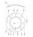
図1は、本発明の実施形態が適用されうる例示的なコンタクトレンズの実施形態(100)の全体構造を示し、レンズを縮尺通りではない正面図(100a)および断面(100b)図で示す。例示的なコンタクトレンズの実施形態(100)の正面図は、光中心(101)と、光ゾーン(102)と、ブレンドゾーン(103)と、対称である非光学周辺キャリアゾーン(104)とレンズ直径(105)とを含む基材をさらに示す。この代表例では、レンズの直径はおよそ14mmであり、光ゾーンの直径はおよそ8mmであり、ブレンドゾーンの幅はおよそ0.25mmであり、キャリアゾーンの幅はおよそ2.75mmである。Figure 1 shows the overall structure of an exemplary contact lens embodiment (100) to which embodiments of the present invention may be applied, showing the lens in a front view (100a) and a cross-sectional view (100b) that are not to scale. The front view of the exemplary contact lens embodiment (100) further shows a substrate including an optical center (101), an optical zone (102), a blend zone (103), a symmetric non-optical peripheral carrier zone (104) and a lens diameter (105). In this representative example, the lens diameter is approximately 14 mm, the optical zone diameter is approximately 8 mm, the blend zone width is approximately 0.25 mm, and the carrier zone width is approximately 2.75 mm.
図2は、別の例示的なコンタクトレンズの実施形態の縮尺通りではない正面図(200a)および断面図(200b)を示す。この例示的なコンタクトレンズの実施形態の正面図は、光中心(201)と、光ゾーン(202)と、ブレンドゾーン(203)と、非光学周辺キャリアゾーン(204)とを含む基材をさらに示す。この代表例では、レンズの直径はおよそ14mmであり、光ゾーン(202)は球面円柱または乱視またはトーリックまたは非対称であり、光ゾーンは楕円形であり、水平方向の径がおよそ8mm、垂直方向の径がおよそ7.5mmであり、ブレンドゾーンは水平経線で幅およそ0.25mm、垂直経線で幅およそ0.38mmであり、対称周辺キャリアゾーンは幅およそ2.75mmである。対称周辺キャリアゾーン(204)のラジアル断面(204a~204h)は、同じまたは実質的に類似の厚さプロファイルを有する。2 shows a front view (200a) and a cross-sectional view (200b) of another exemplary contact lens embodiment, not to scale. The front view of this exemplary contact lens embodiment further shows a substrate including an optical center (201), an optical zone (202), a blend zone (203), and a non-optical peripheral carrier zone (204). In this representative example, the lens has a diameter of approximately 14 mm, the optical zone (202) is sphero-cylindrical or astigmatic or toric or asymmetric, the optical zone is elliptical, has a horizontal diameter of approximately 8 mm and a vertical diameter of approximately 7.5 mm, the blend zone is approximately 0.25 mm wide at the horizontal meridian and approximately 0.38 mm wide at the vertical meridian, and the symmetric peripheral carrier zone is approximately 2.75 mm wide. The radial cross sections (204a-204h) of the symmetric peripheral carrier zone (204) have the same or substantially similar thickness profiles.
ある実施形態では、異なるラジアル断面(204a~204h)に沿った厚さプロファイルの差は、レンズの光学中心の周りの所望の眼上回転を達成するように構成されうる。好ましい眼上回転は、周辺厚さプロファイルを全ての半経線にわたって回転対称に保つことによって達成されうる。In some embodiments, the difference in thickness profile along different radial cross sections (204a-204h) can be configured to achieve a desired on-eye rotation about the optical center of the lens. A preferred on-eye rotation can be achieved by keeping the peripheral thickness profile rotationally symmetric across all semi-meridians.
例えば、ラジアル厚さプロファイル(例えば204a~204h)は、他の任意のラジアル断面の厚さプロファイルがレンズの中心から任意の所与の距離で実質的に同一であるかまたは4%、6%、8%、または10%変動以内であるように構成されうる。For example, the radial thickness profiles (e.g., 204a-204h) can be configured such that the thickness profile of any other radial cross section is substantially the same or within 4%, 6%, 8%, or 10% variation at any given distance from the center of the lens.
一例では、ラジアル厚さプロファイル204aは、レンズの中心から任意の所与の距離で204eのラジアル厚さプロファイルの5%、8%または10%変動以内である。別の例では、ラジアル厚さプロファイル204cは、レンズの中心から任意の所与の距離で204gのラジアル厚さプロファイルの4%、6%または8%変動以内である。In one example,
さらに別の例では、ラジアル厚さプロファイル(例えば204a~204h)は、任意の断面の厚さプロファイルが、レンズの中心から任意の所与の距離で全てのラジアル断面の平均から4%、6%、8%、または10%変動以内であるように構成されうる。非光学周辺キャリアゾーンの製造されたラジアル厚さプロファイル、例えば204a~204hがそれらの公称プロファイルに一致するかを確かめるために、定義されたラジアル距離でのコンタクトレンズのアジマス方向に沿った厚さの断面測定が所望されうる。いくつかの他の例では、非光学周辺キャリアゾーンの一つのラジアル断面で測定されるピーク厚さが別のラジアル断面で測定されるピーク厚さと比較されうる。In yet another example, the radial thickness profiles (e.g., 204a-204h) can be configured such that the thickness profile of any cross section is within 4%, 6%, 8%, or 10% variation from the average of all radial cross sections at any given distance from the center of the lens. Cross-sectional measurements of thickness along the azimuth direction of the contact lens at defined radial distances may be desired to verify that the manufactured radial thickness profiles of the non-optical peripheral carrier zones, e.g., 204a-204h, match their nominal profiles. In some other examples, the peak thickness measured at one radial cross section of the non-optical peripheral carrier zone can be compared to the peak thickness measured at another radial cross section.
いくつかの実施形態では、一つ以上のラジアル断面の間のピーク厚さの差は、20μm、30μm、40μm、50μm、または60μm以下でありうる。いくつかの実施形態では、一つ以上の直角ラジアル断面の間のピーク厚さの差は、20μm、30μm、40μm、50μm、または60μm以下でありうる。In some embodiments, the difference in peak thickness between one or more radial sections may be 20 μm, 30 μm, 40 μm, 50 μm, or 60 μm or less. In some embodiments, the difference in peak thickness between one or more perpendicular radial sections may be 20 μm, 30 μm, 40 μm, 50 μm, or 60 μm or less.
この代表例では、コンタクトレンズの実施形態(200)の球面円柱または乱視またはトーリック光ゾーン(202)の球面屈折力は、-3D近視眼を矯正するための-3Dの球面屈折力および眼の網膜で経線乱視を誘発または導入するための+1.25DCの円柱屈折力を有する。本開示のいくつかの他の例では、近視眼を矯正および管理するためのコンタクトレンズの球面屈折力は、-0.5D~-12Dの間であり得、近視眼の網膜で所望の経線乱視を誘発または導入するための望ましい乱視またはトーリックまたは円柱屈折力は、+0.75DC~+2.5DCの間の範囲でありうる。In this representative example, the spherical power of the sphero-cylindrical or astigmatic or toric optical zone (202) of the contact lens embodiment (200) has a spherical power of -3D to correct -3D myopia and a cylinder power of +1.25DC to induce or introduce meridian astigmatism at the retina of the eye. In some other examples of the present disclosure, the spherical power of the contact lens to correct and manage myopia can be between -0.5D and -12D, and the desired astigmatic or toric or cylinder power to induce or introduce the desired meridian astigmatism at the retina of the myopic eye can range between +0.75DC and +2.5DC.
図3は、図2に示される例示的なコンタクトレンズ(300)の実施形態の正面図を示す。この図は、コンタクトレンズの実施形態(300)、特に光中心(301)の周りに定義された光学ゾーン(302)の向きに対する下(303)および上(304)眼瞼の影響を図式的に示す。Figure 3 shows a front view of the exemplary contact lens (300) embodiment shown in Figure 2. This figure illustrates diagrammatically the effect of the lower (303) and upper (304) eyelids on the contact lens embodiment (300), and in particular the orientation of the optical zone (302) defined about the optical center (301).
下(303)および上(304)眼瞼の複合動作によって促進される自然な瞬きに起因して、コンタクトレンズ(300)は、光学中心(301)の上または周りで回転しうる。これにより、実質的に光学中心または光学軸を中心として定義された光学ゾーン(302)によって与えられる乱視またはトーリックまたは非対称の刺激の向きおよび位置が、実質的に自由な回転および/または偏心を提供する瞬きとともに変動し、その結果、近視の装用者の進行速度を減少させるための時間的および空間的に変動する刺激がもたらされることができ、近視を管理する効果は経時的に実質的に一貫したままである。Due to natural blinking facilitated by the combined movement of the lower (303) and upper (304) eyelids, the contact lens (300) may rotate on or around the optical center (301). This allows the orientation and location of the astigmatic or toric or asymmetric stimulus provided by the optical zone (302) defined substantially about the optical center or optical axis to vary with blinking providing substantially free rotation and/or decentration, resulting in a temporally and spatially varying stimulus for reducing the wearer's rate of progression of myopia, while the effectiveness of managing myopia remains substantially consistent over time.
いくつかの実施形態では、例えば、図2および3を参照して説明されるように、コンタクトレンズは、少なくとも自然な瞬きをする動作の影響下で、実質的に自由な回転が見られるように設計される。例えば、一日のレンズ装用を通して、好ましくは6~12時間にわたって、眼瞼の相互作用により、コンタクトレンズは眼上で多数の異なる向きまたは構成で向けられるように配置されるであろう。実質的に前記コンタクトレンズの光学中心の周りに構成された乱視またはトーリックまたは非対称の光学系に起因して、眼成長の速度を制御するための指向性キューが空間的および時間的に変動するように構成されうる。In some embodiments, for example, as described with reference to Figures 2 and 3, the contact lens is designed to exhibit substantially free rotation at least under the influence of natural blinking motion. For example, throughout a day of lens wear, preferably over a period of 6-12 hours, eyelid interaction will position the contact lens to be oriented on the eye in a number of different orientations or configurations. Directional cues for controlling the rate of eye growth may be configured to vary spatially and temporally due to astigmatic or toric or asymmetric optics configured substantially around the optical center of the contact lens.
いくつかの実施形態では、コンタクトレンズの所望の眼上回転が達成されうるように、コンタクトレンズの実施形態の表面パラメータ、例えばバック表面半径および/または非球面性は、個々の眼に合わせられる。例えば、前記コンタクトレンズは、レンズ装用中の眼上回転の発生を増加させるために、眼の角膜の最も平坦な経線の曲率半径よりも少なくとも0.3mm平坦であるように構成されうる。In some embodiments, the surface parameters of the contact lens embodiment, such as the back surface radius and/or asphericity, are tailored to an individual eye so that a desired on-eye rotation of the contact lens can be achieved. For example, the contact lens can be configured to be at least 0.3 mm flatter than the radius of curvature of the flattest meridian of the cornea of the eye to increase the occurrence of on-eye rotation during lens wear.
他の実施形態では、コンタクトレンズは、レンズ装着から1時間以内に20度未満、および一日一回180度未満の回転を有するように設計されうる。このコンタクトレンズは、挿入時のコンタクトレンズの向きに左右されるレンズの単にランダムな向きによって時間的および空間的に変動する停止信号を生成することがなお可能でありうることが理解されよう。In other embodiments, the contact lens may be designed to have less than 20 degrees rotation within one hour of lens wear and less than 180 degrees rotation once per day. It will be appreciated that the contact lens may still be capable of generating a stop signal that varies in time and space due to merely random orientation of the lens depending on the orientation of the contact lens at the time of insertion.
図4は、矯正されていない-3D近視モデル眼(400)を示す。バージェンスが0Dの可視波長(例えば589nm)の入射光(401)が矯正されていない近視眼に入射したときに、網膜上の結果として生じる像は、焦点ぼけによって引き起こされる対称のぼやけ(402)を有する。この概略図は、網膜面での軸上幾何学的スポット分析を表す。Figure 4 shows an uncorrected -3D myopic model eye (400). When incident light (401) of visible wavelength (e.g. 589 nm) with 0D vergence enters an uncorrected myopic eye, the resulting image on the retina has a symmetric blur (402) caused by defocus. This schematic represents an on-axis geometric spot analysis at the retinal plane.
図5は、図4の-3D近視モデル眼(500)が従来技術の単焦点球面コンタクトレンズ(501)で矯正されたときの網膜面での軸上幾何学的スポット分析の概略図を示す。この例では、バージェンスが0Dの可視波長(例えば589nm)の入射光(502)が矯正された近視眼に入射したときに、網膜上の結果として生じる像は対称の鮮明な焦点(503)を有する。Figure 5 shows a schematic diagram of an on-axis geometric spot analysis at the retinal plane when the -3D myopic model eye (500) of Figure 4 is corrected with a prior art monofocal spherical contact lens (501). In this example, when incident light (502) of visible wavelength (e.g., 589 nm) with 0D vergence is incident on the corrected myopic eye, the resulting image on the retina has a symmetric sharp focus (503).
図6は、図4の-3D近視モデル眼(600)が本明細書に開示される例示的実施形態のコンタクトレンズ(602)で矯正されたときの網膜面での軸上スルーフォーカス幾何学的スポット分析の概略図を示す。この例では、バージェンスが0Dの可視波長(例えば589nm)の入射光(601)が矯正された近視眼(600)に入射したときに、網膜上の結果として生じるスルーフォーカス像は、最小錯乱円(605)ならびにタンジェンシャル面およびサジタル面(604および606)での楕円形ぼやけパターンを有するスタームの円錐体または間隔(603)を形成する。網膜の後ろの像(607および608)はいずれも焦点ずれである。この例では、本開示の例示的実施形態は、サジタル面が網膜上にある一方で、タンジェンシャル面および最小錯乱円がいずれも網膜の前にあるように構成される。ぼやけ円サイズのグラフ寸法は200μmである。Figure 6 shows a schematic diagram of an on-axis through-focus geometric spot analysis at the retinal plane when the -3D myopic model eye (600) of Figure 4 is corrected with an exemplary embodiment contact lens (602) disclosed herein. In this example, when incident light (601) of visible wavelength (e.g., 589 nm) with 0D vergence is incident on the corrected myopic eye (600), the resulting through-focus image on the retina forms a Starm's cone or space (603) with a circle of least confusion (605) and an elliptical blur pattern in the tangential and sagittal planes (604 and 606). The images behind the retina (607 and 608) are both out of focus. In this example, the exemplary embodiment of the present disclosure is configured such that the tangential plane and the circle of least confusion are both in front of the retina while the sagittal plane is on the retina. The graph dimensions of the blur circle size are 200 μm.
網膜の前のタンジェンシャル面(604)の楕円形ぼやけパターンは経線乱視と呼称され、サジタル面(606)の楕円形ぼやけパターンは経線矯正と呼称される。The elliptical blur pattern in the tangential plane (604) in front of the retina is called meridional astigmatism, and the elliptical blur pattern in the sagittal plane (606) is called meridional correction.
別の例では、コンタクトレンズの実施形態(602)は、タンジェンシャル面(604)の楕円形ぼやけパターンが網膜の前にあり、サジタル面(606)の楕円形ぼやけパターンが網膜の後ろにないように処方されうる。スタームの円錐体または間隔の深さ、すなわちサジタル面とタンジェンシャル面との間のスルーフォーカス距離は、約+0.5DC~+3DCの間であるように構成されうる。タンジェンシャル面(604)の楕円形ぼやけパターンの位置は、網膜の0.6mm~0.13mm前の間に位置しうる。サジタル面(606)の楕円形ぼやけパターンの位置は、網膜の約0.13~0mm前の間でありうる。In another example, the contact lens embodiment (602) may be prescribed such that the elliptical blur pattern in the tangential plane (604) is in front of the retina and the elliptical blur pattern in the sagittal plane (606) is not behind the retina. The depth of the Sturm's cone or spacing, i.e., the through-focus distance between the sagittal and tangential planes, may be configured to be between about +0.5 DC and +3 DC. The location of the elliptical blur pattern in the tangential plane (604) may be located between 0.6 mm and 0.13 mm in front of the retina. The location of the elliptical blur pattern in the sagittal plane (606) may be between about 0.13 and 0 mm in front of the retina.
いくつかの例では、前記経線矯正は中心窩下、中心窩、黄斑下、黄斑または傍黄斑領域に限定されうる一方で、他の例では、経線矯正は網膜上のより広い視野角に及び、例えば少なくとも10度、20度、または30度を包含しうる。In some instances, the meridian correction may be limited to the subfoveal, foveal, submacular, macular, or paramacular regions, while in other instances, the meridian correction may span a wider field of view on the retina, encompassing, for example, at least 10 degrees, 20 degrees, or 30 degrees.
いくつかの例では、前記経線乱視は中心窩下、中心窩、黄斑下、黄斑または傍黄斑領域に限定されうる一方で、他の例では、経線乱視は網膜上のより広い視野角に及び、例えば少なくとも10度、20度、または30度を包含しうる。In some instances, the meridian astigmatism may be limited to the subfoveal, foveal, submacular, macular, or paramacular regions, while in other instances, the meridian astigmatism may span a wider angle of vision on the retina, for example encompassing at least 10 degrees, 20 degrees, or 30 degrees.
網膜上の光停止信号の横方向広がりは、乱視もしくはトーリックもしくは非対称の屈折力分布の大きさ、または前記乱視もしくはトーリックもしくは非対称の屈折力分布の表面積によって決定される。The lateral spread of the light-stopping signal on the retina is determined by the magnitude of the astigmatism, toricity or asymmetrical refractive power distribution, or the surface area of said astigmatism, toricity or asymmetrical refractive power distribution.
さらに、回転対称の周辺キャリアゾーンに起因して、網膜の前の光停止刺激すなわち楕円形ぼやけパターンの向きおよび位置は、実質的に経時的に自然な瞬き動作とともに変動する。コンタクトレンズの眼上回転および偏心は、空間的および時間的に変動する信号を提示する。Furthermore, due to the rotationally symmetric peripheral carrier zone, the orientation and position of the light-stop stimulus, i.e., the elliptical blur pattern, in front of the retina varies substantially over time with the natural blinking behavior. On-eye rotation and decentration of the contact lens present spatially and temporally varying signals.
これらの図面および例に開示された特定の構造的および機能的詳細は、限定として読み取られてはならず、開示された実施形態を多数の他のバリエーションにおいて採用することを当業者に教示するための単なる代表的基礎として読み取られねばならない。The specific structural and functional details disclosed in these drawings and examples should not be read as limiting, but merely as a representative basis to teach those skilled in the art to employ the disclosed embodiments in numerous other variations.
図4~6では例示のために概略モデル眼(表1)が選択された。しかし、他の例示的実施形態では、Liou‐Brennan、Escudero‐Navarroおよびその他のような概略レイトレーシングモデル眼が、上の単純なモデル眼の代わりに使用されてもよい。本明細書に開示される実施形態のさらなるシミュレーションを助けるために、角膜、水晶体、網膜、透光体、またはそれらの組み合わせのパラメータを変えてもよい。A schematic model eye (Table 1) was chosen for illustration in Figures 4-6. However, in other exemplary embodiments, schematic ray tracing model eyes such as Liou-Brennan, Escudero-Navarro and others may be used in place of the above simple model eye. Parameters of the cornea, lens, retina, optic body, or combinations thereof may be varied to aid in further simulation of the embodiments disclosed herein.
本明細書に提供される例は、本発明を開示するために-3D近視モデル眼を用いているが、同開示は、他の程度の近視、例えば-1D、-2D、-5Dまたは-6Dに拡張されうる。さらに、当業者が1DCまでの乱視とあわせた様々な程度の近視の眼への拡張を導き出しうるものと理解される。例示的実施形態では589nmの特定の波長に言及したが、当業者が420nm~760nmの間の他の可視波長への拡張を導き出しうるものと理解される。The examples provided herein use a -3D myopic model eye to disclose the invention, but the disclosure may be extended to other degrees of myopia, e.g., -1D, -2D, -5D, or -6D. Furthermore, it is understood that one skilled in the art may derive extensions to eyes with various degrees of myopia combined with astigmatism up to 1 DC. Although the exemplary embodiment refers to a specific wavelength of 589 nm, it is understood that one skilled in the art may derive extensions to other visible wavelengths between 420 nm and 760 nm.
本開示のある実施形態は、自然な瞬き動作に起因して起こるコンタクトレンズの自然な眼上回転および偏心の助けを借りて達成される、時間的および空間的に変動する、換言すれば網膜位置が実質的に経時的に実質的に変動する停止信号を進行中の近視眼に提供しうるコンタクトレンズを対象とする。この時間的および空間的に変動する停止信号は、従来技術で観察される有効性の潜在的な飽和効果を最小化しうる。Certain embodiments of the present disclosure are directed to contact lenses that can provide a time- and space-varying stop signal to an ongoing myopic eye, in other words a stop signal whose retinal position varies substantially over time, achieved with the aid of the natural on-eye rotation and decentration of the contact lens due to the natural blinking motion. This time- and space-varying stop signal can minimize potential saturation effects of efficacy observed in the prior art.
本開示のある実施形態は、コンタクトレンズが装用者によってどの向きに装用または挿入されるかに関わらず、空間的および時間的に変動する停止信号を進行中の近視眼に提供しうるコンタクトレンズを対象とする。Certain embodiments of the present disclosure are directed to contact lenses that can provide a spatially and temporally varying stop signal to an ongoing myopic eye, regardless of the orientation in which the contact lens is worn or inserted by the wearer.
本開示のいくつかの実施形態では、停止信号は、実質的に光中心または光学軸を中心として定義された乱視またはトーリックの非対称の屈折力プロファイルを使用して構成されうる。乱視またはトーリック屈折力プロファイルは、光中心に沿ったラジアルおよび/またはアジマス屈折力分布を使用して構成されうる。In some embodiments of the present disclosure, the stop signal may be configured using an asymmetric astigmatic or toric power profile defined substantially about the optical center or optical axis. The astigmatic or toric power profile may be configured using a radial and/or azimuthal power distribution along the optical center.
図7は、本明細書に開示されるコンタクトレンズの実施形態の乱視、トーリックまたは球面円柱処方(701)のコンタクトレンズの実施形態の一つの光学ゾーン(702)だけの拡大セクションの概略図(700)を示す。本実施形態の光学ゾーン内の屈折力プロファイル分布は、本明細書に開示されるようにラジアル(703)およびアジマス(704)屈折力分布関数を使用して構成される。Figure 7 shows a schematic diagram (700) of a magnified section of only one optical zone (702) of a contact lens embodiment of an astigmatic, toric or spherocylindrical prescription (701) of a contact lens embodiment disclosed herein. The power profile distribution within the optical zone of this embodiment is constructed using radial (703) and azimuth (704) power distribution functions as disclosed herein.
本開示のある実施形態において、乱視またはトーリックまたは非対称の屈折力分布は、下式:トーリック実施形態の屈折力分布=球面+円柱/2*(ラジアル)*(アジマス)屈折力分布関数を用いて構成されうる。いくつかの実施形態では、ラジアル分布関数は、ラジアル屈折力分布=Cρ2の形をとることができ、式中Cは展開係数であり、ロー(ρ)(703)は正規化されたラジアル座標ρ0/ρmaxである。ロー(ρ0)は所与の点でのラジアル座標であるのに対し、ρmaxは光ゾーンの最大ラジアル座標または半直径(705)である。いくつかの実施形態では、アジマス屈折力分布関数は、アジマス屈折力分布=cos mθの形をとることができ、式中mは、いくつかの実施形態において1~6の間の任意の整数であり得、シータ(θ)はアジマス角(704)である。 In certain embodiments of the present disclosure, an astigmatic or toric or asymmetric power distribution may be constructed using the following formula: Power Distribution for Toric Embodiments = Spherical + Cylinder / 2* (Radial)* (Azimuth) Power Distribution Function. In some embodiments, the radial distribution function may take the form Radial Power Distribution =Cρ2 , where C is an expansion coefficient and rho (ρ) (703) is the normalized radial coordinate ρ0 /ρmax . Rho (ρ0 ) is the radial coordinate at a given point while ρmax is the maximum radial coordinate or semi-diameter of the optical zone (705). In some embodiments, the azimuth power distribution function may take the form Azimuth Power Distribution = cos mθ, where m may be any integer between 1 and 6 in some embodiments and theta (θ) is the azimuth angle (704).
本開示のある実施形態では、ほとんどの角膜がいくらかの乱視を有するかまたは矯正を必要とするのに十分に高い眼球乱視を有しうる事実に対処する必要がありうる。角膜または眼球乱視は、コンタクトレンズの円柱屈折力と好都合または不都合に組み合わされ得、企図された実施形態の視覚性能の変動をもたらしうる。Certain embodiments of the present disclosure may need to address the fact that most corneas have some astigmatism or may have ocular astigmatism high enough to require correction. Corneal or ocular astigmatism may combine favorably or unfavorably with the cylindrical power of a contact lens, resulting in variability in the visual performance of contemplated embodiments.
このような性能の変動は、近視進行の有効性の観点から判定される治療または管理効果にとって有益でありうるが、性能の変動は、装用者にとって顕著であるかまたは場合によっては煩わしいものでありうる。このような視覚性能の変動を減少するいくつかの方法は、眼球乱視を矯正するためにトーリックレンズを使用することによって達成されうる。Although such variations in performance may be beneficial for treatment or management outcomes as measured in terms of effectiveness of myopia progression, the variations in performance may be noticeable or even bothersome to the wearer. Some methods of reducing such variations in visual performance may be achieved by using toric lenses to correct ocular astigmatism.
そのような場合には、安定化されたレンズが必要であり得、経時的にレンズを回転させる特定の指示を伴って異なる円柱屈折力および/または軸の複数のコンタクトレンズが人の眼に処方されるかまたは複数のコンタクトレンズ対が人の眼に施用されうる。In such cases, stabilized lenses may be necessary and multiple contact lenses of different cylinder powers and/or axes may be prescribed to the person's eye or multiple contact lens pairs may be applied to the person's eye with specific instructions for rotating the lenses over time.
例えば、異なる日、週、または月に異なるレンズ対が装用されうる。それぞれの眼に二つ以上のレンズが特定の指示の下で装用されるときには、設計の変動により、近視の進行を遅くするための類似の空間的および時間的治療効果を達成することができ、近視の進行を遅くすることは経時的に実質的に一貫している。For example, different lens pairs may be worn on different days, weeks, or months. When two or more lenses are worn in each eye under specific instructions, variations in design can achieve similar spatial and temporal therapeutic effects for slowing myopia progression, and the slowing of myopia progression is substantially consistent over time.
複数のコンタクトレンズは、装用者および眼科医に不便さをもたらすために本開示の好ましい実施形態ではないかもしれないが、本発明の代替的な使用方法として当業者に提供するためにここで企図され取り込まれる。Although multiple contact lenses may not be a preferred embodiment of the present disclosure due to the inconvenience they may cause to the wearer and ophthalmologist, they are contemplated and incorporated herein to provide those skilled in the art with an alternative method of using the present invention.
例えば少なくとも+1.25DC、+1.5DC、+1.75DCまたは+2DCの矯正を必要とするより高い量の乱視の問題に取り組むための本開示の別の実施形態では、罹患眼の球面円柱誤差に対処するために装用されるように眼鏡のレンズが処方されてもよく、眼鏡のレンズと同時に装用されるように専用コンタクトレンズが処方されてもよく、このコンタクトレンズは、時間的および空間的に変動する停止信号として働くように望ましいレベルの乱視またはトーリシティを誘発するように構成される。In another embodiment of the present disclosure to address the problem of higher amounts of astigmatism, e.g., requiring correction of at least +1.25 DC, +1.5 DC, +1.75 DC or +2 DC, a spectacle lens may be prescribed to be worn to address the sphero-cylindrical error of the affected eye, and a specialized contact lens may be prescribed to be worn simultaneously with the spectacle lens, the contact lens configured to induce a desired level of astigmatism or toricity to act as a time- and spatially-varying stop signal.
本開示の例示的実施形態の光学性能結果のシミュレーションのために、概略モデル眼が使用された(図8~図31)。光学モデリングおよび性能のシミュレーションに使用された概略モデル眼の処方パラメータを表1にまとめる。A schematic model eye was used to simulate the optical performance results of the exemplary embodiments of the present disclosure (FIGS. 8-31). The prescription parameters of the schematic model eye used for the optical modeling and performance simulation are summarized in Table 1.
この処方は、589nmの単色波長のために定義された-3D近視眼を提示する。表1に記載される処方は、企図された例示的実施形態の効果を実証するための必須の方法として解釈されてはならない。これは、光学シミュレーションの目的で当業者によって使用されうる多くの方法のうちの一つにすぎない。四(4)つの例示的なコンタクトレンズの実施形態の処方が表2に提供される。This prescription presents a -3D myopia defined for a monochromatic wavelength of 589 nm. The prescriptions set forth in Table 1 should not be construed as a required method for demonstrating the effects of the contemplated exemplary embodiments. It is merely one of many methods that may be used by one of ordinary skill in the art for purposes of optical simulation. Prescriptions for four (4) exemplary contact lens embodiments are provided in Table 2.

モデルコンタクトレンズの例示的実施形態のパラメータは、性能効果に関して光ゾーンをシミュレートするだけである。時間の関数としての性能変動を実証するために、表面上の偏心/傾き関数を使用して、in vivoで生理的に起こるであろう並進および回転が再現されている。光学性能結果のシミュレーションのために、例示的実施形態は0°、45°、90°および135°回転され、または水平および垂直経線に沿って±0.75mm偏心された。The parameters of the exemplary embodiment of the model contact lens only simulate the optical zone with respect to performance effects. To demonstrate performance variations as a function of time, the translations and rotations that would occur physiologically in vivo are replicated using surface decenter/tilt functions. For simulation of optical performance results, the exemplary embodiment was rotated 0°, 45°, 90° and 135° or decentered ±0.75 mm along the horizontal and vertical meridians.
図8は、直径8mmの光ゾーンにわたる例示的実施形態(実施例#1)の2次元屈折力マップ(単位D)を示す。レンズは、-3Dの球面屈折力および+1DCの円柱屈折力で構成され、屈折力プロファイルが二つの主経線に分解されると、一方の主経線(垂直実線、801)はおよそ-3Dの屈折力を有し、他方の主経線(水平破線、802)はおよそ-2Dの屈折力を有する。Figure 8 shows a two-dimensional power map (in D) of an example embodiment (Example #1) across an 8 mm diameter optical zone. The lens is configured with -3D spherical power and +1DC cylindrical power, and when the power profile is decomposed into two principal meridians, one principal meridian (vertical solid line, 801) has approximately -3D power and the other principal meridian (horizontal dashed line, 802) has approximately -2D power.
破線と実線との交点である光学中心の周りのアジマスにわたる屈折力変動は、本明細書に記載されるように単純な余弦分布にしたがう。図8で説明されるコンタクトレンズは、-3D近視モデル眼に少なくとも部分的に中心窩矯正、または少なくとも部分的に経線矯正を提供し、モデル眼の網膜で誘発または導入された経線停止信号をさらに提供するように構成される。The power variation across azimuth around the optical center, which is the intersection of the dashed and solid lines, follows a simple cosine distribution as described herein. The contact lens described in FIG. 8 is configured to provide at least partial foveal correction, or at least partial meridian correction, to a −3D myopic model eye, and further provide a meridian stop signal induced or introduced at the retina of the model eye.
この例では、主経線(801)は少なくとも部分的に経線矯正を提供し、主経線(802)はモデル眼の網膜で経線停止信号を提供する。In this example, the principal meridian (801) provides at least partial meridian correction, and the principal meridian (802) provides a meridian stop signal at the retina of the model eye.
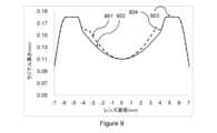
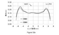
図9は、本発明の例示的実施形態の断面厚さプロファイルを示す。コンタクトレンズの実施例#1(図8)について、光ゾーンの急勾配(901)および平坦(902)セクションに沿った直角経線の二つの厚さプロファイルが示される。Figure 9 shows cross-sectional thickness profiles of an exemplary embodiment of the present invention. For contact lens example #1 (Figure 8), two thickness profiles are shown at perpendicular meridians along the steep (901) and flat (902) sections of the optic zone.
図8に描かれたコンタクトレンズの実施形態の球面円柱屈折力分布は、長軸(902、弱主経線)および短軸(901、強主経線)を備えた楕円形の光学ゾーンをもたらす。この例示的実施形態では、短軸(901、強主経線)と非光学周辺キャリアゾーン(903)との間のゾーンは、段階的遷移またはブレンディングゾーン(904)を生じる。The sphero-cylindrical power distribution of the contact lens embodiment depicted in FIG. 8 results in an elliptical optical zone with a major axis (902, weak principal meridian) and a minor axis (901, strong principal meridian). In this exemplary embodiment, the zone between the minor axis (901, strong principal meridian) and the non-optical peripheral carrier zone (903) creates a gradual transition or blending zone (904).
この例示的実施形態では、例示的実施形態(実施例#1)の主経線にわたる屈折力変動は最小(すなわち平坦な屈折力プロファイル)であるように設計された。しかし、本開示のいくつかの他の実施形態では、主経線にわたる屈折力の変動が企図される。図9に見ることができるように、レンズの周辺非光学ゾーンは実質的に回転対称のキャリアゾーンを有する。この設計は、上眼瞼および下眼瞼の複合動作によって促進される自然な瞬きに起因するコンタクトレンズの実施形態(実施例#1)の光学中心の上またはその周りでの実質的に自由な回転を促進し、これがさらに、光学ゾーンによって与えられる乱視刺激を瞬きとともに変動させ、その結果近視の進行速度を減少させるための時間的および空間的に変動する刺激がもたらされ、眼成長の進行を減少させる指向性キューおよび有効性は経時的に実質的に一貫したままである。In this exemplary embodiment, the exemplary embodiment (Example #1) was designed to have minimal power variation across the principal meridian (i.e., a flat power profile). However, in some other embodiments of the present disclosure, power variation across the principal meridian is contemplated. As can be seen in FIG. 9, the peripheral non-optical zone of the lens has a substantially rotationally symmetric carrier zone. This design promotes substantially free rotation on or around the optical center of the contact lens embodiment (Example #1) due to natural blinking facilitated by the combined action of the upper and lower eyelids, which in turn causes the astigmatic stimulus provided by the optical zone to vary with blinking, resulting in a temporally and spatially varying stimulus for reducing the rate of myopia progression, while the directional cue and effectiveness of reducing eye growth progression remains substantially consistent over time.
バージェンスが0Dの可視波長(589nm)の入射光が例示的実施形態(実施例#1)で矯正された表1の近視眼に入射したときに、レンズの主経線を0°(1001)、45°(1002)、90°(1003)および135°(1104)に置いて結果として生じる網膜面での軸上の時間的および空間的に変動する点広がり関数が図10に示される。When incident light of visible wavelength (589 nm) with 0D vergence is incident on the myopic eye of Table 1 corrected with the exemplary embodiment (Example #1), the resulting on-axis, temporally and spatially varying point spread functions at the retinal plane are shown in Figure 10 with the lens principal meridian at 0° (1001), 45° (1002), 90° (1003) and 135° (1104).
例示的実施形態(実施例#1)の回転対称の周辺キャリアゾーンは、網膜上のサジタル面の点広がり関数として描かれた乱視刺激が自然な瞬き動作とともにコンタクトレンズの回転に起因して変動することを促進し、眼に時間的および空間的に変動する信号を提供する。The rotationally symmetric peripheral carrier zone of the exemplary embodiment (Example #1) facilitates the astigmatic stimulus depicted as a sagittal point spread function on the retina to vary due to contact lens rotation with natural blinking, providing a temporally and spatially varying signal to the eye.
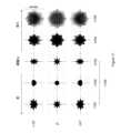
図11は、広角(すなわち±10°視野)の時間的および空間的に変動する信号を示し、コンタクトレンズの実施形態の主経線は、経時的なコンタクトレンズの回転をシミュレートするために光学中心の周りで0°、45°、90°および135°回転されている。Figure 11 shows the temporally and spatially varying signal for a wide angle (i.e., ±10° field of view) where the principal meridian of a contact lens embodiment has been rotated 0°, 45°, 90° and 135° about the optical center to simulate contact lens rotation over time.
図11のスルーフォーカス幾何学的スポット図は、コンタクトレンズの実施形態が-3D近視モデル眼に装着され、空間的および時間的に変動する光停止信号をもたらす前記コンタクトレンズの眼上回転をまねて4つの異なる構成(0°、45°、90°および135°)でさらに回転されたときに得られる応答を積分することによって得られる光停止信号の時間積分の表現である。The through-focus geometric spot diagram in FIG. 11 is a representation of the time integral of the light stopping signal obtained by integrating the response obtained when an embodiment of the contact lens is placed on a −3D myopic model eye and further rotated in four different configurations (0°, 45°, 90° and 135°) mimicking on-eye rotation of the contact lens resulting in a spatially and temporally varying light stopping signal.

網膜面の周りのスルーフォーカス幾何学的スポット分析は、五(5)つの位置1101~1105で計算され、列1101および1102は網膜の-0.3mmおよび-0.1mm前の網膜位置を表し、列1103は網膜上0mmの位置を表し、列1104および1105は網膜の+0.3mmおよび+0.1mm後ろの網膜位置を表す。Through-focus geometric spot analysis around the retinal plane is calculated at five (5) locations 1101-1105, with
見て取れるように、網膜の周りのスルーフォーカス像のモンタージュは、タンジェンシャル面(1101)およびサジタル面(1103)ならびに最小錯乱円(1102)を包含する楕円形ぼやけパターンを有するスタームの円錐体または間隔(1100)を形成する。網膜の後ろでは、楕円形ぼやけパターン(1104、1105)のサイズが大きくなり続ける。好ましい構成では、コンタクトレンズの実施形態は、楕円形焦点の一方(タンジェンシャル)が網膜の前にあり、他方の楕円形焦点(サジタル)が網膜上にあるように処方される。As can be seen, the montage of the through-focus image around the retina forms a Starm's cone or interval (1100) with an elliptical blur pattern encompassing the tangential (1101) and sagittal (1103) planes and the circle of least confusion (1102). Behind the retina, the elliptical blur patterns (1104, 1105) continue to grow in size. In a preferred configuration, the contact lens embodiment is prescribed such that one of the elliptical foci (tangential) is in front of the retina and the other elliptical focus (sagittal) is on the retina.
網膜の前のタンジェンシャル面(1101)の楕円形ぼやけパターンは経線乱視と呼称され、サジタル面(1103)の楕円形ぼやけパターンは経線矯正と呼称される。本開示の他の例では、コンタクトレンズの実施形態は、両方の楕円形焦点(タンジェンシャルおよびサジタル)が網膜の前にあるように処方されることができ、この例では、サジタル面のポジションは、少なくとも部分的に眼への経線矯正を提供するように構成される。さらに別の構成において、コンタクトレンズの実施形態は、楕円形焦点の一方(タンジェンシャル)が網膜の前にあり、最小錯乱円が網膜上にあるように処方されうる。さらに、これらの企図された構成の各々においては、企図された実施形態の中に構成された回転対称の周辺キャリアゾーンのおかげで、網膜の前または網膜上の乱視またはトーリック光刺激は、自然な瞬き動作とともに眼上のコンタクトレンズの回転に起因して変動し、時間的および空間的に変動する光信号を提供する。The elliptical blur pattern in the tangential plane (1101) in front of the retina is referred to as meridional astigmatism, and the elliptical blur pattern in the sagittal plane (1103) is referred to as meridional correction. In another example of the present disclosure, contact lens embodiments can be prescribed such that both elliptical foci (tangential and sagittal) are in front of the retina, in which example the position of the sagittal plane is configured to provide at least a partial meridional correction to the eye. In yet another configuration, contact lens embodiments can be prescribed such that one of the elliptical foci (tangential) is in front of the retina and the circle of least confusion is on the retina. Furthermore, in each of these contemplated configurations, by virtue of the rotationally symmetric peripheral carrier zone configured in the contemplated embodiments, the astigmatic or toric light stimulus in front of or on the retina varies due to the rotation of the contact lens on the eye with the natural blinking motion, providing a temporally and spatially varying light signal.
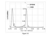
図12は、可視波長(589nm)のバージェンスが0Dの入射光が本明細書に記載されるコンタクトレンズの実施形態(実施例1)で矯正された表1の-3D近視モデル眼に入射したときの、時間的および空間的に変動する点広がり関数の主経線および直角経線についての光学伝達関数の軸上スルーフォーカス絶対値として描かれた網膜信号を示す。Figure 12 shows the retinal signal plotted as the on-axis through-focus absolute value of the optical transfer function for the principal and perpendicular meridians of the time- and spatially varying point spread function when incident light of visible wavelength (589 nm) with 0D vergence is incident on a -3D myopic model eye of Table 1 corrected with an embodiment of a contact lens described herein (Example 1).
この例示的実施形態では、主経線の光学伝達関数のピークは、網膜面またはそのわずかに前に位置し、これにより-3D近視眼への少なくとも部分的に中心窩矯正または少なくとも部分的に経線矯正が提供される。In this exemplary embodiment, the peak of the optical transfer function of the principal meridian is located at or slightly anterior to the retinal plane, thereby providing at least a partial foveal correction or at least a partial meridian correction to the −3D myopic eye.
直角経線の光学伝達関数のピークは網膜の約0.38mm前にあり、これにより誘発または導入された経線停止信号が提供される。この例では、主経線および直角経線のピークは、それぞれサジタル面およびタンジェンシャル面の楕円形ぼやけパターンと同義である。The peak of the optical transfer function for the perpendicular meridian is approximately 0.38 mm anterior to the retina, providing an induced or induced meridian stop signal. In this example, the peaks of the principal and perpendicular meridians are synonymous with elliptical blur patterns in the sagittal and tangential planes, respectively.
いくつかの他の実施形態では、主経線の光学伝達関数のピークは、網膜上にあってもよく、網膜から0.1mmより前ではない。いくつかの他の実施形態では、直角経線の光学伝達関数のピークは、網膜のおよそ0.25mm、0.35mm、0.45mm、または0.6mm前でありうる。いくつかの実施形態では、主経線と直角経線のピークの間の距離は、光停止信号に寄与する所望のレベルの誘発された経線乱視を達成しながら視覚性能を改善するために最適化されうる。In some other embodiments, the peak of the optical transfer function of the principal meridian may be on the retina and not more than 0.1 mm anterior to the retina. In some other embodiments, the peak of the optical transfer function of the perpendicular meridian may be approximately 0.25 mm, 0.35 mm, 0.45 mm, or 0.6 mm anterior to the retina. In some embodiments, the distance between the peaks of the principal and perpendicular meridians may be optimized to improve visual performance while achieving a desired level of induced meridian astigmatism that contributes to the light stopping signal.
図13は、直径8mmの光ゾーンにわたる例示的実施形態(実施例#2)の2次元屈折力マップ(単位D)を示す。レンズは、-3Dの球面屈折力および+1.5DCの円柱屈折力で構成され、屈折力プロファイルが二つの主経線に分解されると、一方の主経線(垂直実線、1301)はおよそ-3Dの屈折力を有し、他方の主経線(水平破線、1302)はおよそ-1.5Dの屈折力を有する。破線と実線との交点である光学中心の周りのアジマスにわたる屈折力変動は、本明細書に記載されるように単純な余弦分布にしたがう。Figure 13 shows a two-dimensional power map (in D) of an example embodiment (Example #2) across an 8 mm diameter optical zone. The lens is configured with -3D spherical power and +1.5DC cylindrical power, and when the power profile is decomposed into two principal meridians, one principal meridian (vertical solid line, 1301) has approximately -3D power and the other principal meridian (horizontal dashed line, 1302) has approximately -1.5D power. The power variation across azimuth around the optical center, the intersection of the dashed and solid lines, follows a simple cosine distribution as described herein.
レンズは、表1に記載される-3Dの近視モデル眼への少なくとも部分的に中心窩矯正、または少なくとも部分的に経線矯正に用いられる一つの主経線に沿って-3Dの球面屈折力を有し、+1.5DCの乱視またはトーリックまたは円柱屈折力がモデル眼の網膜で誘発された経線停止信号を提供する。The lens has a spherical power of -3D along one principal meridian used for at least partial foveal or at least partial meridian correction to the -3D myopic model eye described in Table 1, and a +1.5 DC astigmatism or toric or cylindrical power to provide the meridian stop signal induced at the retina of the model eye.
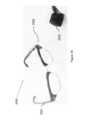
図14は、トーリック光ゾーンを備えた従来技術のレンズの厚さプロファイルを示す。図14の従来技術のレンズは、プリズムバラスト安定化ゾーンを有する。プリズムバラストレンズの垂直および水平経線のラジアル厚さプロファイルをより詳しく調べると、-3.00/+1.50x90°の処方の従来技術のレンズに典型的である。Figure 14 shows the thickness profile of a prior art lens with a toric optic zone. The prior art lens of Figure 14 has a prism ballast stabilization zone. Looking more closely at the radial thickness profile in the vertical and horizontal meridians of the prism ballast lens, it is typical of a prior art lens with a -3.00/+1.50 x 90° prescription.
水平セクション(1401)は対称である一方、垂直セクションは、眼に装着されたときに安定した向きを提供するために、厚い下部(1402)および薄い上部(1403)を有する。垂直セクションの急勾配の厚さの曲率および水平経線における平坦な厚さの曲率は必要とされる角膜乱視に一致し、これにより任意の経線に沿って良好な視力が提供される。The horizontal section (1401) is symmetrical, while the vertical section has a thicker lower section (1402) and a thinner upper section (1403) to provide a stable orientation when worn on the eye. The steeper thickness curvature of the vertical section and the flatter thickness curvature in the horizontal meridian match the required corneal astigmatism, thereby providing good vision along any meridian.
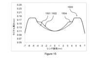
対して、図15は、本発明の例示的実施形態(実施例#2)の厚さプロファイルを示す。コンタクトレンズの実施形態(実施例#2)の、光ゾーンの急勾配および平坦セクションに沿った直角経線の二つの厚さプロファイルが示される。図13に描かれたコンタクトレンズの実施形態の球面円柱屈折力分布は、長軸(1502、弱主経線)および短軸(1501、強主経線)を備えた楕円形の光学ゾーンをもたらす。In contrast, FIG. 15 shows the thickness profile of an exemplary embodiment of the present invention (Example #2). Two thickness profiles are shown for the perpendicular meridians along the steep and flat sections of the optic zone of the contact lens embodiment (Example #2). The sphero-cylindrical power distribution of the contact lens embodiment depicted in FIG. 13 results in an elliptical optic zone with a major axis (1502, the weak principal meridian) and a minor axis (1501, the strong principal meridian).
この例示的実施形態では、短軸(1501、強主経線)と非光学周辺キャリアゾーン(1503)との間のゾーンは、段階的遷移またはブレンディングゾーン(1504)を生じる。この例示的実施形態では、例示的実施形態(実施例#2)の主経線にわたる屈折力変動は最小(すなわち平坦な屈折力プロファイル)であるように設計された。In this exemplary embodiment, the zone between the minor axis (1501, the steepest meridian) and the non-optical peripheral carrier zone (1503) creates a gradual transition or blending zone (1504). In this exemplary embodiment, the exemplary embodiment (Example #2) was designed to have minimal power variation (i.e., a flat power profile) across the principal meridian.
図15に見ることができるように、レンズの周辺非光学ゾーンは実質的に回転対称のキャリアゾーンを有する。この設計は、上眼瞼および下眼瞼の複合動作によって促進される自然な瞬きに起因するコンタクトレンズの実施形態(実施例#2)の光学中心の上またはその周りでの実質的に自由な回転を促進し、これがさらに、光学ゾーンによって与えられる乱視刺激を瞬きとともに変動させ、その結果近視の装用者の近視の進行速度を減少させるための時間的および空間的に変動する刺激がもたらされ、眼成長の速度を減少させる指向性キューおよび効率は経時的に実質的に一貫したままである。As can be seen in FIG. 15, the peripheral non-optical zone of the lens has a substantially rotationally symmetric carrier zone. This design facilitates substantially free rotation on or around the optical center of the contact lens embodiment (Example #2) due to natural blinking facilitated by the combined action of the upper and lower eyelids, which in turn causes the astigmatic stimulus provided by the optical zone to vary with blinking, resulting in a temporally and spatially varying stimulus for reducing the rate of myopic progression in myopic wearers, while the directional cue and efficiency of reducing the rate of eye growth remain substantially consistent over time.
バージェンスが0Dの可視波長(589nm)の入射光が例示的実施形態(実施例#2)で矯正された表1の近視眼に入射したときに、レンズの主経線を0°(1601)、45°(1602)、90°(1603)および135°(1604)に置いて結果として生じる網膜面での軸上の時間的および空間的に変動する点広がり関数が図16に示される。認められるように、実施例1を用いて得られた結果(図10)と比較すると、実施例2(図16)では網膜で捕捉される軸上点広がり関数の長さが増加しており、これはこのコンタクトレンズの実施形態(実施例#2)の円柱屈折力の増加に起因する。When incident light of visible wavelength (589 nm) with 0D vergence is incident on the myopic eye of Table 1 corrected with an exemplary embodiment (Example #2), the resulting on-axis, temporally and spatially varying point spread functions at the retinal plane are shown in FIG. 16 with the lens principal meridian at 0° (1601), 45° (1602), 90° (1603) and 135° (1604). As can be seen, compared to the results obtained with Example 1 (FIG. 10), Example 2 (FIG. 16) has an increased length of the on-axis point spread function captured at the retina, which is due to the increased cylindrical power of this contact lens embodiment (Example #2).
例示的実施形態(実施例#2)の回転対称の周辺キャリアゾーンは、網膜上のサジタル面の点広がり関数として描かれた乱視刺激が自然な瞬き動作とともにコンタクトレンズの回転に起因して変動することを促進し、眼に時間的および空間的に変動する信号を提供する。The rotationally symmetric peripheral carrier zone of the exemplary embodiment (Example #2) facilitates the astigmatic stimulus depicted as a sagittal point spread function on the retina to vary due to contact lens rotation with natural blinking, providing a temporally and spatially varying signal to the eye.
図17は、広角(すなわち±10°視野)の時間的および空間的に変動する信号を示し、コンタクトレンズの実施形態(実施例#2)の主経線は、経時的なコンタクトレンズの回転をシミュレートするために光学中心の周りで0°、45°、90°および135°回転されている。図17のスルーフォーカス幾何学的スポット図は、コンタクトレンズの実施形態が-3D近視モデル眼に装着され、空間的および時間的に変動する光停止信号をもたらす前記コンタクトレンズの眼上回転をまねて4つの異なる構成(0°、45°、90°および135°)でさらに回転されたときに得られる応答を積分することによって得られる光停止信号の時間積分の表現である。Figure 17 shows the time- and spatially varying signal for a wide angle (i.e. ±10° field of view) where the principal meridian of a contact lens embodiment (Example #2) has been rotated 0°, 45°, 90° and 135° about the optical center to simulate contact lens rotation over time. The through-focus geometric spot diagram in Figure 17 is a representation of the time integral of the light stopping signal obtained by integrating the response obtained when a contact lens embodiment is placed on a -3D myopic model eye and further rotated in four different configurations (0°, 45°, 90° and 135°) mimicking on-eye rotation of said contact lens resulting in a spatially and temporally varying light stopping signal.
網膜面の周りのスルーフォーカス幾何学的スポット分析は、五(5)つの位置1701~1705で計算され、列1701および1702は網膜の-0.3mmおよび-0.15mm前の網膜位置を表し、列1703は網膜上0mmの位置を表し、列1704および1705は網膜の+0.3mmおよび+0.15mm後ろの網膜位置を表す。Through-focus geometric spot analysis around the retinal plane is calculated at five (5) locations 1701-1705, with
見て取れるように、網膜の周りのスルーフォーカス像のモンタージュは、タンジェンシャル面(1701)およびサジタル面(1703)ならびに最小錯乱円(1702)を包含する楕円形ぼやけパターンを有するスタームの円錐体または間隔(1700)を形成する。網膜の後ろでは、楕円形ぼやけパターン(1704、1705)のサイズが大きくなり続ける。好ましい構成では、コンタクトレンズの実施形態は、楕円形焦点の一方(タンジェンシャル)が網膜の前にあり、他方の楕円形焦点(サジタル)が網膜上にあるように処方される。As can be seen, the montage of the through-focus image around the retina forms a Starm's cone or interval (1700) with an elliptical blur pattern encompassing the tangential (1701) and sagittal (1703) planes and the circle of least confusion (1702). Behind the retina, the elliptical blur patterns (1704, 1705) continue to grow in size. In a preferred configuration, the contact lens embodiment is prescribed such that one of the elliptical foci (tangential) is in front of the retina and the other elliptical focus (sagittal) is on the retina.
実施例1(図11)と比較すると、実施例2(図17)で得られたスルーフォーカス像に描かれたサジタル面およびタンジェンシャル面の長さが増加しており、これはこのレンズの実施形態(実施例#2)の円柱屈折力の増加に起因する。各スポット図のスケールは300μmであることが注目される。Compared to Example 1 (Figure 11), the lengths of the sagittal and tangential surfaces depicted in the through-focus image obtained in Example 2 (Figure 17) are increased, which is due to the increased cylindrical power of this lens embodiment (Example #2). Note that the scale of each spot diagram is 300 μm.
本開示の他の例では、コンタクトレンズの実施形態は、両方の楕円形焦点(タンジェンシャルおよびサジタル)が網膜の前にあるように処方されうる。さらに別の構成において、コンタクトレンズの実施形態は、楕円形焦点の一方(タンジェンシャル)が網膜の前にあり、最小錯乱円が網膜上にあるように処方されうる。In another example of the present disclosure, contact lens embodiments can be prescribed such that both elliptical foci (tangential and sagittal) are in front of the retina. In yet another configuration, contact lens embodiments can be prescribed such that one of the elliptical foci (tangential) is in front of the retina and the circle of least confusion is on the retina.
さらに、これらの企図された構成の各々においては、企図された実施形態の中に構成された回転対称の周辺キャリアゾーンのおかげで、網膜の前または網膜上の乱視またはトーリック光刺激は、自然な瞬き動作とともに眼上のコンタクトレンズの回転に起因して変動し、時間的および空間的に変動する光信号を提供する。Furthermore, in each of these contemplated configurations, by virtue of the rotationally symmetric peripheral carrier zone configured in the contemplated embodiments, the astigmatic or toric light stimulus in front of or on the retina varies due to the rotation of the contact lens on the eye along with the natural blinking motion, providing a temporally and spatially varying light signal.
図18は、可視波長(589nm)のバージェンスが0Dの入射光が本明細書に記載されるコンタクトレンズの実施形態(実施例2)で矯正された表1の-3D近視モデル眼に入射したときの、時間的および空間的に変動する点広がり関数の主経線および直角経線についての光学伝達関数の軸上スルーフォーカス絶対値として描かれた網膜信号を示す。Figure 18 shows the retinal signal plotted as the on-axis through-focus absolute value of the optical transfer function for the principal and perpendicular meridians of the time- and spatially varying point spread function when incident light of visible wavelength (589 nm) with 0D vergence is incident on a -3D myopic model eye of Table 1 corrected with an embodiment of a contact lens described herein (Example 2).
この例示的実施形態では、主経線の光学伝達関数のピークは、網膜面またはそのわずかに前に位置し、これにより-3D近視眼への少なくとも部分的に中心窩矯正または少なくとも部分的に経線矯正が提供される。In this exemplary embodiment, the peak of the optical transfer function of the principal meridian is located at or slightly anterior to the retinal plane, thereby providing at least a partial foveal correction or at least a partial meridian correction to the −3D myopic eye.
直角経線の光学伝達関数のピークは網膜の約0.64mm前にあり、これにより誘発または導入された経線停止信号が提供される。この例では、主経線および直角経線のピークは、それぞれサジタル面およびタンジェンシャル面の楕円形ぼやけパターンと同義である。The peak of the optical transfer function for the perpendicular meridian is approximately 0.64 mm anterior to the retina, providing an induced or induced meridian stop signal. In this example, the peaks of the principal and perpendicular meridians are synonymous with elliptical blur patterns in the sagittal and tangential planes, respectively.
いくつかの他の実施形態では、主経線の光学伝達関数のピークは、網膜上にあってもよく、網膜から0.1mmより前ではない。いくつかの他の実施形態では、直角経線の光学伝達関数のピークは、網膜のおよそ0.25mm、0.35mm、0.45mm、または0.6mm前でありうる。いくつかの実施形態では、主経線と直角経線のピークの間の距離は、光停止信号に寄与する所望のレベルの誘発された経線乱視を達成しながら視覚性能を改善するために最適化されうる。In some other embodiments, the peak of the optical transfer function of the principal meridian may be on the retina and not more than 0.1 mm anterior to the retina. In some other embodiments, the peak of the optical transfer function of the perpendicular meridian may be approximately 0.25 mm, 0.35 mm, 0.45 mm, or 0.6 mm anterior to the retina. In some embodiments, the distance between the peaks of the principal and perpendicular meridians may be optimized to improve visual performance while achieving a desired level of induced meridian astigmatism that contributes to the light stopping signal.
図19は、直径8mmの光ゾーンにわたる例示的実施形態(実施例#3)の2次元屈折力マップ(単位D)を示す。レンズは-3Dの球面屈折力および+1.5DCの円柱屈折力で構成され、球形円柱屈折力分布に加えて、レンズは光学ゾーンの端に定義された-0.75Dの一次球面収差で構成される。Figure 19 shows a two-dimensional power map (in D) of an exemplary embodiment (Example #3) across an 8 mm diameter optic zone. The lens is configured with -3D spherical power and +1.5DC cylinder power, and in addition to the spherocylinder power distribution, the lens is configured with -0.75D primary spherical aberration defined at the edge of the optic zone.
屈折力マップが二つの主経線に分解されると、一方の主経線(垂直実線、1901)はおよそ-3Dの屈折力を有し、上に定義された大きさの負の一次球面収差が光ゾーン全体に定義され、他方の主経線(水平破線、1902)はおよそ-1.5Dの屈折力を有し、上に定義された大きさの負の一次球面収差が光ゾーン全体に定義される。破線と実線との交点である光学中心の周りのアジマスにわたる屈折力変動は、本明細書に記載されるように複素余弦分布にしたがう。When the power map is decomposed into two principal meridians, one principal meridian (vertical solid line, 1901) has a power of approximately -3D and a negative primary spherical aberration of the magnitude defined above is defined throughout the optical zone, and the other principal meridian (horizontal dashed line, 1902) has a power of approximately -1.5D and a negative primary spherical aberration of the magnitude defined above is defined throughout the optical zone. The power variation across azimuth about the optical center, the intersection of the dashed and solid lines, follows a complex cosine distribution as described herein.
いくつかの例示的実施形態では、実質的に非対称の屈折力分布は、球面+アジマス成分の式によって記述される屈折力分布関数を用いて表され、式中、球面は眼を矯正するための距離球面処方屈折力を指し、屈折力分布関数のアジマス成分はCa*cos(mθ)として記述され、式中、Caはアジマス係数であり、mは1~6の間の整数であり、シータ(θ)は光ゾーンの所与の点のアジマス角である。 In some exemplary embodiments, the substantially asymmetric power distribution is represented with a power distribution function described by the equation sphere+azimuth component, where sphere refers to the distance spherical prescription power for correcting the eye, and the azimuth component of the power distribution function is described as Ca* cos(mθ), where Ca is the azimuth coefficient, m is an integer between 1 and 6, and theta (θ) is the azimuth angle of a given point in the optical zone.
いくつかの他の例示的実施形態では、実質的に非対称の屈折力分布は、球面+(ラジアル成分)*(アジマス成分)の式によって記述される屈折力分布関数を用いて表され、式中、球面は近視眼を矯正するための距離球面処方屈折力を指し、屈折力分布関数のラジアル成分はCr*ρとして記述され、式中、Crは展開係数であり、ロー(ρ)は正規化されたラジアル座標(ρ0/ρmax)であり、屈折力分布関数のアジマス成分はCa*cos(mθ)として記述され、式中、mは1~6の間の任意の整数であり得、シータ(θ)はアジマス角であり、ロー(ρ0)は所与の点でのラジアル座標であり、ρmaxは光ゾーンの最大ラジアル座標または半直径である。実施例#3のコンタクトレンズの実施形態は、表1に記載される-3D近視モデル眼への少なくとも部分的に中心窩矯正、または少なくとも部分的に経線矯正を提供するように構成され、実質的に光学軸を中心とする非対称の屈折力分布(アジマスの周りの複素余弦分布を定義した)がモデル眼の網膜で誘発された経線停止信号を提供する。本開示の他の実施形態では、コンタクトレンズの光ゾーン全体にわたって定義される変動する他の大きさの一次球面収差、例えば-0.5D、-1D、-1.25Dがより望ましい可能性がある。本開示のいくつかの他の実施形態では、所望の大きさの正の球面収差が光ゾーンの小さなエリア、例えば5mm、6mm、または7mmにわたって構成されうる。 In some other exemplary embodiments, the substantially asymmetric power distribution is represented with a power distribution function described by the formula sphere + (radial component)* (azimuth component), where sphere refers to the distance spherical prescription power for correcting myopia, the radial component of the power distribution function is described as Cr* ρ, where Cr is an expansion coefficient, rho (ρ) is the normalized radial coordinate (ρ0 /ρmax ), and the azimuth component of the power distribution function is described as Ca* cos(mθ), where m can be any integer between 1 and 6, theta (θ) is the azimuth angle, rho (ρ0 ) is the radial coordinate at a given point, and ρmax is the maximum radial coordinate or semi-diameter of the optical zone. The contact lens embodiment of
図20は、本発明の例示的実施形態(実施例#3)の断面厚さプロファイルを示す。コンタクトレンズの実施例#3について、光ゾーンの急勾配(2001)および平坦(2002)セクションに沿った直角経線の二つの厚さプロファイルが示される。この例示的実施形態では、図19に描かれたコンタクトレンズの実施形態のアジマス方向に沿って定義される、光学中心の周りの複素余弦分布として表されうる非対称の屈折力分布は、長軸(2002、弱主経線)および短軸(2001、強主経線)を備えた楕円形の光学ゾーンをもたらす。20 shows a cross-sectional thickness profile of an exemplary embodiment of the present invention (Example #3). For contact
この例示的実施形態では、短軸(2001、強主経線)と非光学周辺キャリアゾーン(2003)との間のゾーンは、段階的遷移またはブレンディングゾーン(2004)を生じる。図20に見ることができるように、レンズの周辺非光学ゾーンは実質的に回転対称のキャリアゾーンを有する。この設計は、上眼瞼および下眼瞼の複合動作によって促進される自然な瞬きに起因するコンタクトレンズの実施形態(実施例#3)の光学中心の上またはその周りでの実質的に自由な回転を促進し、これがさらに、光学ゾーンによって与えられる乱視刺激を瞬きとともに変動させ、その結果近視の装用者における進行速度を減少させるための時間的および空間的に変動する刺激がもたらされ、眼成長の進行を減少させる指向性キューおよび有効性は経時的に実質的に一貫したままである。In this exemplary embodiment, the zone between the minor axis (2001, the steepest meridian) and the non-optical peripheral carrier zone (2003) creates a gradual transition or blending zone (2004). As can be seen in FIG. 20, the peripheral non-optical zone of the lens has a substantially rotationally symmetric carrier zone. This design promotes substantially free rotation on or around the optical center of the contact lens embodiment (Example #3) due to natural blinking facilitated by the combined action of the upper and lower eyelids, which in turn causes the astigmatic stimulus provided by the optical zone to vary with blinking, resulting in a temporally and spatially varying stimulus for reducing the rate of progression in myopic wearers, with the directional cue and effectiveness of reducing eye growth progression remaining substantially consistent over time.
バージェンスが0Dの可視波長(589nm)の入射光が例示的実施形態(実施例#3)で矯正された表1の近視眼に入射したときに、レンズの主経線を0°(2101)、45°(2202)、90°(2203)および135°(2204)に置いて結果として生じる網膜面での軸上の時間的および空間的に変動する点広がり関数が図21に示される。When incident light of visible wavelength (589 nm) with 0D vergence is incident on the myopic eye of Table 1 corrected with the exemplary embodiment (Example #3), the resulting on-axis, temporally and spatially varying point spread functions at the retinal plane are shown in Figure 21 with the lens principal meridian at 0° (2101), 45° (2202), 90° (2203) and 135° (2204).
認められるように、実施例1および2を用いて得られた結果(図10および16)と比較すると、実施例3(図21)では網膜で捕捉される軸上点広がり関数の長さが減少しており、これはこのコンタクトレンズの実施形態(実施例#3)の中への負の一次球面収差の導入に起因する。As can be seen, compared to the results obtained with Examples 1 and 2 (Figures 10 and 16), Example 3 (Figure 21) has a reduced length of the on-axis point spread function captured at the retina, which is due to the introduction of negative primary spherical aberration in this contact lens embodiment (Example #3).
例示的実施形態(実施例#3)の回転対称の周辺キャリアゾーンは、網膜上のサジタル面の点広がり関数として描かれた乱視刺激が自然な瞬き動作とともにコンタクトレンズの回転に起因して変動することを促進し、眼に時間的および空間的に変動する信号を提供する。The rotationally symmetric peripheral carrier zone of the exemplary embodiment (Example #3) facilitates the astigmatic stimulus depicted as a sagittal point spread function on the retina to vary due to contact lens rotation with natural blinking, providing a temporally and spatially varying signal to the eye.
図22は、広角(すなわち±10°視野)の時間的および空間的に変動する信号を示し、コンタクトレンズの実施形態(実施例#3)の主経線は、経時的なコンタクトレンズの回転をシミュレートするために光学中心の周りで0°、45°、90°および135°回転されている。Figure 22 shows the temporally and spatially varying signal for a wide angle (i.e., ±10° field of view) where the principal meridian of a contact lens embodiment (Example #3) has been rotated 0°, 45°, 90°, and 135° about the optical center to simulate contact lens rotation over time.
図22のスルーフォーカス幾何学的スポット図は、コンタクトレンズの実施形態が-3D近視モデル眼に装着され、空間的および時間的に変動する光停止信号をもたらす前記コンタクトレンズの眼上回転をまねて4つの異なる構成(0°、45°、90°および135°)でさらに回転されたときに得られる応答を積分することによって得られる光停止信号の時間積分の表現である。The through-focus geometric spot diagram in FIG. 22 is a representation of the time integral of the light stopping signal obtained by integrating the response obtained when an embodiment of the contact lens is placed on a −3D myopic model eye and further rotated in four different configurations (0°, 45°, 90° and 135°) mimicking on-eye rotation of the contact lens resulting in a spatially and temporally varying light stopping signal.
網膜面の周りのスルーフォーカス幾何学的スポット分析は、五(5)つの位置2201~2205で計算され、列2201および2202は網膜の-0.3mmおよび-0.15mm前の網膜位置を表し、列2203は網膜上0mmの位置を表し、列2204および2205は網膜の+0.3mmおよび+0.15mm後ろの網膜位置を表す。Through-focus geometric spot analysis around the retinal plane is calculated at five (5) locations 2201-2205, with
見て取れるように、網膜の周りのスルーフォーカス像のモンタージュは、タンジェンシャル面(2201)およびサジタル面(2203)ならびに最小錯乱円(2202)を包含する楕円形ぼやけパターンを有するスタームの円錐体または間隔(2200)を形成する。網膜の後ろでは、楕円形ぼやけパターン(2204、2205)のサイズが大きくなり続ける。好ましい構成では、コンタクトレンズの実施形態は、楕円形焦点の一方(タンジェンシャル)が網膜の前にあり、他方の楕円形焦点(サジタル)が網膜上にあるように処方される。As can be seen, the montage of the through-focus image around the retina forms a Starm's cone or interval (2200) with an elliptical blur pattern encompassing the tangential (2201) and sagittal (2203) planes and the circle of least confusion (2202). Behind the retina, the elliptical blur patterns (2204, 2205) continue to grow in size. In a preferred configuration, the contact lens embodiment is prescribed such that one of the elliptical foci (tangential) is in front of the retina and the other elliptical focus (sagittal) is on the retina.
実施例1および2(図11および17)と比較すると、実施例2(図17)で得られたスルーフォーカス像に描かれたサジタル面およびタンジェンシャル面の長さが、このレンズの実施形態(実施例#2)の中への負の一次球面収差の導入に起因して減少している。各スポット図のスケールは300μmであることが注目される。本開示の他の例では、コンタクトレンズの実施形態は、両方の楕円形焦点(タンジェンシャルおよびサジタル)が網膜の前にあるように処方されうる。さらに別の構成において、コンタクトレンズの実施形態は、楕円形焦点の一方(タンジェンシャル)が網膜の前にあり、最小錯乱円が網膜上にあるように処方されうる。さらに、これらの企図された構成の各々においては、企図された実施形態の中に構成された回転対称の周辺キャリアゾーンのおかげで、網膜の前または網膜上の非対称のぼやけ刺激は、自然な瞬き動作とともに眼上のコンタクトレンズの回転に起因して変動し、時間的および空間的に変動する光信号を提供する。Compared to Examples 1 and 2 (Figures 11 and 17), the lengths of the sagittal and tangential planes depicted in the through-focus image obtained in Example 2 (Figure 17) are reduced due to the introduction of negative primary spherical aberration into this lens embodiment (Example #2). It is noted that the scale of each spot diagram is 300 μm. In other examples of the present disclosure, contact lens embodiments can be prescribed such that both elliptical foci (tangential and sagittal) are in front of the retina. In yet another configuration, contact lens embodiments can be prescribed such that one of the elliptical foci (tangential) is in front of the retina and the circle of least confusion is on the retina. Furthermore, in each of these contemplated configurations, by virtue of the rotationally symmetric peripheral carrier zone configured in the contemplated embodiments, the asymmetric blur stimuli in front of or on the retina vary due to the rotation of the contact lens on the eye with the natural blinking motion, providing a temporally and spatially varying optical signal.
図23は、可視波長(589nm)のバージェンスが0Dの入射光が本明細書に記載されるコンタクトレンズの実施形態(実施例3)で矯正された表1の-3D近視モデル眼に入射したときの、時間的および空間的に変動する点広がり関数の主経線および直角経線についての光学伝達関数の軸上スルーフォーカス絶対値として描かれた網膜信号を示す。Figure 23 shows the retinal signal plotted as the on-axis through-focus absolute value of the optical transfer function for the principal and perpendicular meridians of the time- and spatially varying point spread function when incident light of visible wavelength (589 nm) with 0D vergence is incident on a -3D myopic model eye of Table 1 corrected with an embodiment of a contact lens described herein (Example 3).
この例示的実施形態では、主経線の光学伝達関数のピークは、網膜面またはそのわずかに前に位置し、これにより-3D近視眼への少なくとも部分的に中心窩矯正または少なくとも部分的に経線矯正が提供される。直角経線の光学伝達関数のピークは網膜の約0.42mm前にあり、これにより誘発または導入された経線停止信号が提供される。この例では、主経線および直角経線のピークは、それぞれサジタル面およびタンジェンシャル面の楕円形ぼやけパターンと同義である。In this exemplary embodiment, the peak of the optical transfer function of the principal meridian is located at or slightly anterior to the retinal plane, thereby providing at least a partial foveal correction or at least a partial meridian correction to the −3D myopic eye. The peak of the optical transfer function of the perpendicular meridian is approximately 0.42 mm anterior to the retina, thereby providing an induced or induced meridian stop signal. In this example, the peaks of the principal and perpendicular meridians are synonymous with elliptical blur patterns in the sagittal and tangential planes, respectively.
いくつかの他の実施形態では、主経線の光学伝達関数のピークは、網膜上にあってもよく、網膜から0.1mmより前ではない。いくつかの他の実施形態では、直角経線の光学伝達関数のピークは、網膜のおよそ0.25mm、0.35mm、0.45mm、または0.6mm前でありうる。いくつかの実施形態では、主経線と直角経線のピークの間の距離は、光停止信号に寄与する所望のレベルの誘発された経線乱視を達成しながら視覚性能を改善するために最適化されうる。In some other embodiments, the peak of the optical transfer function of the principal meridian may be on the retina and not more than 0.1 mm anterior to the retina. In some other embodiments, the peak of the optical transfer function of the perpendicular meridian may be approximately 0.25 mm, 0.35 mm, 0.45 mm, or 0.6 mm anterior to the retina. In some embodiments, the distance between the peaks of the principal and perpendicular meridians may be optimized to improve visual performance while achieving a desired level of induced meridian astigmatism that contributes to the light stopping signal.
図24は、直径8mmの光ゾーンにわたる例示的実施形態(実施例#4)の2次元屈折力マップ(単位D)を示す。レンズは-3Dの球面屈折力および+1.5DCの円柱屈折力で構成され、球形円柱屈折力分布に加えて、レンズは光学ゾーンの端に定義された+0.75Dの一次球面収差で構成される。屈折力マップが二つの主経線に分解されると、一方の主経線(垂直実線、2401)はおよそ-3Dの屈折力を有し、上に定義された大きさの正の一次球面収差が光ゾーン全体に定義され、他方の主経線(水平破線、2402)はおよそ-1.5Dの屈折力を有し、上に定義された大きさの正の一次球面収差が光ゾーン全体に定義される。破線と実線との交点である光学中心の周りのアジマスにわたる屈折力変動は、本明細書に記載されるように複素余弦分布にしたがう。Figure 24 shows a two-dimensional power map (in D) of an exemplary embodiment (Example #4) across an 8 mm diameter optical zone. The lens is configured with -3D spherical power and +1.5DC cylinder power, and in addition to the spherocylinder power distribution, the lens is configured with +0.75D primary spherical aberration defined at the edge of the optical zone. When the power map is decomposed into two principal meridians, one principal meridian (vertical solid line, 2401) has a power of approximately -3D and a positive primary spherical aberration of the magnitude defined above is defined throughout the optical zone, and the other principal meridian (horizontal dashed line, 2402) has a power of approximately -1.5D and a positive primary spherical aberration of the magnitude defined above is defined throughout the optical zone. The power variation across azimuth around the optical center, which is the intersection of the dashed and solid lines, follows a complex cosine distribution as described herein.
いくつかの例示的実施形態では、実質的に非対称の屈折力分布は、少なくとも部分的に(n,m)の一般式の第一種ベッセル円関数の項の少なくとも一つ以上を用いて記述される屈折力分布関数を用いて表され、ベッセル円関数の項の少なくとも一つ以上は、nが1、2、3の値をとり、mが±2の値をとるときに得られる。いくつかの他の例示的実施形態では、アジマス屈折力分布関数はcos2(mθ)の形であり、mは両端値を含む1~6の間の整数である。 In some exemplary embodiments, the substantially asymmetric power distribution is represented by a power distribution function that is at least partially described by at least one or more terms of a Bessel circle function of the first kind of the general formula (n,m), where n takes values of 1, 2, 3, and m takes values of ±2. In some other exemplary embodiments, the azimuth power distribution function is of the formcos2 (mθ), where m is an integer between 1 and 6, inclusive.
実施例#4のコンタクトレンズの実施形態は、表1に記載される-3D近視モデル眼への少なくとも部分的に中心窩矯正、または少なくとも部分的に経線矯正を提供するように構成され、光学軸の周りの非対称の屈折力分布(アジマスの周りの複素余弦分布を定義した)がモデル眼の網膜で誘発された経線停止信号を提供する。The contact lens embodiment of
本開示の他の実施形態では、コンタクトレンズの光ゾーン全体にわたって定義される変動する他の大きさの一次球面収差、例えば+0.5D、+1D、+1.25Dがより望ましい可能性がある。本開示のいくつかの他の実施形態では、所望の大きさの正の球面収差が光ゾーンの小さなエリア、例えば5mm、6mm、または7mmにわたって構成されうる。In other embodiments of the present disclosure, other magnitudes of varying primary spherical aberration defined across the optic zone of the contact lens may be more desirable, e.g., +0.5D, +1D, +1.25D. In some other embodiments of the present disclosure, the desired magnitude of positive spherical aberration may be configured over a small area of the optic zone, e.g., 5mm, 6mm, or 7mm.
図25は、本発明の例示的実施形態(実施例#4)の断面厚さプロファイルを示す。コンタクトレンズの実施例#4について、光ゾーンの急勾配(2501)および平坦(2502)セクションに沿った直角経線の二つの厚さプロファイルが示される。この例示的実施形態では、図24に描かれたコンタクトレンズの実施形態のアジマス方向に沿って定義される、光学中心の周りの複素余弦分布として表されうる非対称の屈折力分布は、長軸(2502、弱主経線)および短軸(2501、強主経線)を備えた楕円形の光学ゾーンをもたらす。この例示的実施形態では、短軸(2501、強主経線)と非光学周辺キャリアゾーン(2503)との間のゾーンは、段階的遷移またはブレンディングゾーン(2504)を生じる。25 shows a cross-sectional thickness profile of an exemplary embodiment of the present invention (Example #4). For contact
図25に見ることができるように、レンズの周辺非光学ゾーンは実質的に回転対称のキャリアゾーンを有する。この設計は、上眼瞼および下眼瞼の複合動作によって促進される自然な瞬きに起因するコンタクトレンズの実施形態(実施例#4)の光学中心の上またはその周りでの実質的に自由な回転を促進し、これがさらに、光学ゾーンによって与えられる非対称刺激を瞬きとともに変動させ、その結果近視の装用者における進行速度を減少させるための時間的および空間的に変動する刺激がもたらされ、眼成長の進行を減少させる指向性キューおよび有効性は経時的に実質的に一貫したままである。As can be seen in FIG. 25, the peripheral non-optical zone of the lens has a substantially rotationally symmetric carrier zone. This design facilitates substantially free rotation on or around the optical center of the contact lens embodiment (Example #4) due to natural blinking facilitated by the combined action of the upper and lower eyelids, which in turn causes the asymmetric stimulus provided by the optical zone to vary with blinking, resulting in a temporally and spatially varying stimulus for reducing progression rate in myopic wearers, with the directional cue and effectiveness of reducing eye growth progression remaining substantially consistent over time.
バージェンスが0Dの可視波長(589nm)の入射光が例示的実施形態(実施例#4)で矯正された表1の近視眼に入射したときに、レンズの主経線を0°(2601)、45°(2602)、90°(2603)および135°(2604)に置いて結果として生じる網膜面での軸上の時間的および空間的に変動する点広がり関数が図26に示される。When incident light of visible wavelength (589 nm) with 0D vergence is incident on the myopic eye of Table 1 corrected with an exemplary embodiment (Example #4), the resulting on-axis, temporally and spatially varying point spread functions at the retinal plane are shown in Figure 26 with the lens principal meridian at 0° (2601), 45° (2602), 90° (2603) and 135° (2604).
認められるように、実施例3を用いて得られた結果(図21)と比較すると、実施例4(図26)では網膜で捕捉される軸上点広がり関数がわずかに鮮明であり、これはこのコンタクトレンズの実施形態(実施例#4)の中への正の一次球面収差の導入に起因する。例示的実施形態(実施例#4)の回転対称の周辺キャリアゾーンは、網膜上のサジタル面の点広がり関数として描かれた非対称刺激が自然な瞬き動作とともにコンタクトレンズの回転に起因して変動することを促進し、眼に時間的および空間的に変動する信号を提供する。As can be seen, the on-axis point spread function captured at the retina is slightly sharper in Example 4 (FIG. 26) compared to the results obtained with Example 3 (FIG. 21), which is due to the introduction of a positive primary spherical aberration in this contact lens embodiment (Example #4). The rotationally symmetric peripheral carrier zone of the exemplary embodiment (Example #4) facilitates the asymmetric stimulus depicted as a sagittal point spread function on the retina that varies due to contact lens rotation with the natural blinking motion, providing a temporally and spatially varying signal to the eye.
図27は、広角(すなわち±10°視野)の時間的および空間的に変動する信号を示し、コンタクトレンズの実施形態(実施例#4)の主経線は、経時的なコンタクトレンズの回転をシミュレートするために光学中心の周りで0°、45°、90°および135°回転されている。図27のスルーフォーカス幾何学的スポット図は、コンタクトレンズの実施形態が-3D近視モデル眼に装着され、空間的および時間的に変動する光停止信号をもたらす前記コンタクトレンズの眼上回転をまねて4つの異なる構成(0°、45°、90°および135°)でさらに回転されたときに得られる応答を積分することによって得られる光停止信号の時間積分の表現である。網膜面の周りのスルーフォーカス幾何学的スポット分析は、五(5)つの位置2701~2705で計算され、列2701および2702は網膜の-0.3mmおよび-0.15mm前の網膜位置を表し、列2703は網膜上0mmの位置を表し、列2704および2705は網膜の+0.3mmおよび+0.15mm後ろの網膜位置を表す。図から分かるように、網膜の周りのスルーフォーカス像のモンタージュは、タンジェンシャル面(2701)およびサジタル面(2703)ならびに最小錯乱円(2702)を包含する楕円形ぼやけパターンを有するスタームの円錐体または間隔(2700)を形成する。網膜の後ろでは、楕円形ぼやけパターン(2704、2705)のサイズが大きくなり続ける。好ましい構成では、コンタクトレンズの実施形態は、楕円形焦点の一方(タンジェンシャル)が網膜の前にあり、他方の楕円形焦点(サジタル)が網膜上にあるように処方される。実施例2(図17)と比較すると、実施例4(図27)のスルーフォーカス像はわずかに増加しており、これはこのレンズの負の球面収差に起因する。各スポット図のスケールは300μmであることが注目される。Figure 27 shows the time- and spatially varying signal for a wide angle (i.e. ±10° field of view) where the principal meridian of a contact lens embodiment (Example #4) has been rotated 0°, 45°, 90° and 135° about the optical center to simulate contact lens rotation over time. The through-focus geometric spot diagram in Figure 27 is a representation of the time integral of the light stopping signal obtained by integrating the response obtained when a contact lens embodiment is placed on a -3D myopic model eye and further rotated in four different configurations (0°, 45°, 90° and 135°) mimicking on-eye rotation of said contact lens resulting in a spatially and temporally varying light stopping signal. A through-focus geometric spot analysis around the retinal plane is calculated at five (5) locations 2701-2705, with
本開示の他の例では、コンタクトレンズの実施形態は、両方の楕円形焦点(タンジェンシャルおよびサジタル)が網膜の前にあるように処方されうる。さらに別の構成において、コンタクトレンズの実施形態は、楕円形焦点の一方(タンジェンシャル)が網膜の前にあり、最小錯乱円が網膜上にあるように処方されうる。さらに、これらの企図された構成の各々においては、企図された実施形態の中に構成された回転対称の周辺キャリアゾーンのおかげで、網膜の前または網膜上の非対称のぼやけ刺激は、自然な瞬き動作とともに眼上のコンタクトレンズの回転に起因して変動し、時間的および空間的に変動する光信号を提供する。In other examples of the present disclosure, contact lens embodiments may be prescribed such that both elliptical foci (tangential and sagittal) are in front of the retina. In yet another configuration, contact lens embodiments may be prescribed such that one of the elliptical foci (tangential) is in front of the retina and the circle of least confusion is on the retina. Furthermore, in each of these contemplated configurations, by virtue of the rotationally symmetric peripheral carrier zone configured in the contemplated embodiments, the asymmetric blur stimulus in front of or on the retina varies due to the rotation of the contact lens on the eye with the natural blinking motion, providing a temporally and spatially varying optical signal.
図28は、可視波長(589nm)のバージェンスが0Dの入射光が本明細書に記載されるコンタクトレンズの実施形態(実施例4)で矯正された表1の-3D近視モデル眼に入射したときの、時間的および空間的に変動する点広がり関数の主経線および直角経線についての光学伝達関数の軸上スルーフォーカス絶対値として描かれた網膜信号を示す。この例示的実施形態では、主経線の光学伝達関数のピークは、網膜面またはそのわずかに前に位置し、これにより-3D近視眼への少なくとも部分的に中心窩矯正または少なくとも部分的に経線矯正が提供される。直角経線の光学伝達関数のピークは網膜の約0.45mm前にあり、これにより誘発または導入された経線停止信号が提供される。この例では、主経線および直角経線のピークは、それぞれサジタル面およびタンジェンシャル面の楕円形ぼやけパターンと同義である。いくつかの他の実施形態では、主経線の光学伝達関数のピークは、網膜上にあってもよく、網膜から0.1mmより前ではない。いくつかの他の実施形態では、直角経線の光学伝達関数のピークは、網膜のおよそ0.25mm、0.35mm、0.45mm、または0.6mm前でありうる。いくつかの実施形態では、主経線と直角経線のピークの間の距離は、光停止信号に寄与する所望のレベルの誘発された経線乱視を達成しながら視覚性能を改善するために最適化されうる。バージェンスが0Dの可視波長(589nm)の入射光が例示的実施形態(実施例#2)で矯正された表1の近視眼に入射したときに、レンズがx軸に沿って0.75mm(2901)および-0.75mm(2902)ならびにy軸に沿って0.75mm(2903)および-0.75mm(2904)偏心されて網膜面で結果として生じる軸上偏心点広がり関数が図29に示される。28 shows the retinal signal plotted as the on-axis through-focus absolute value of the optical transfer function for the principal and perpendicular meridians of the time- and space-varying point spread function when incident light of 0D vergence at visible wavelength (589 nm) is incident on the −3D myopic model eye of Table 1 corrected with an embodiment of the contact lens described herein (Example 4). In this exemplary embodiment, the peak of the optical transfer function of the principal meridian is located at or slightly anterior to the retinal plane, thereby providing at least a partial foveal correction or at least a partial meridian correction to the −3D myopic eye. The peak of the optical transfer function of the perpendicular meridian is approximately 0.45 mm anterior to the retina, thereby providing an induced or induced meridian stop signal. In this example, the peaks of the principal and perpendicular meridians are synonymous with elliptical blur patterns in the sagittal and tangential planes, respectively. In some other embodiments, the peak of the optical transfer function of the principal meridian may be on the retina and not more than 0.1 mm anterior to the retina. In some other embodiments, the peak of the optical transfer function of the perpendicular meridian may be approximately 0.25 mm, 0.35 mm, 0.45 mm, or 0.6 mm in front of the retina. In some embodiments, the distance between the peak of the principal meridian and the perpendicular meridian may be optimized to improve visual performance while achieving a desired level of induced meridian astigmatism contributing to the light stop signal. When incident light of visible wavelength (589 nm) with 0D vergence is incident on the myopic eye of Table 1 corrected with the exemplary embodiment (Example #2), the lens is decentered 0.75 mm (2901) and -0.75 mm (2902) along the x-axis and 0.75 mm (2903) and -0.75 mm (2904) along the y-axis, resulting on-axis decentering point spread functions at the retinal plane are shown in FIG. 29.
図30は、表1の-3D近視モデル眼が本明細書に開示される例示的実施形態の一つ(実施例#2)で矯正されたときの、網膜面の周りの広角(すなわち±10°視野)の時間的および空間的に変動する(すなわちレンズが経時的にx軸およびy軸に沿って±0.75mm偏心される)幾何学的スポット分析を示す。図30のスルーフォーカス幾何学的スポット図は、コンタクトレンズの実施形態が-3D近視モデル眼に装着され、空間的および時間的に変動する光停止信号をもたらす前記コンタクトレンズの眼上回転をまねて2つの異なる構成(x軸およびy軸に沿って±0.75mm)でさらに偏心されたときに得られる応答を積分することによって得られる光停止信号の空間積分の表現である。Figure 30 shows a wide-angle (i.e., ±10° field) time- and spatially-varying (i.e., the lens is decentered ±0.75 mm along the x- and y-axes over time) geometric spot analysis around the retinal plane when the -3D myopic model eye of Table 1 is corrected with one of the exemplary embodiments disclosed herein (Example #2). The through-focus geometric spot diagram of Figure 30 is a representation of the spatial integral of the light stopping signal obtained by integrating the response obtained when an embodiment of a contact lens is placed on the -3D myopic model eye and further decentered in two different configurations (±0.75 mm along the x- and y-axes) mimicking on-eye rotation of the contact lens resulting in a spatially and temporally-varying light stopping signal.
見て取れるように、網膜の周りのスルーフォーカス像のモンタージュは、サジタル面(3002)およびタンジェンシャル面(3003)ならびに最小錯乱円(3001)を備えた楕円形ぼやけパターンを有するスタームの円錐体または間隔(3000)を形成する。網膜の後ろでは、ぼやけパターン(3004、3005)のサイズが大きくなり続ける。コンタクトレンズの実施形態は、楕円形焦点の一つが網膜の前にあるように処方される。さらに、回転対称の周辺キャリアゾーンに起因して、網膜の前の刺激は自然な瞬き動作とともに、すなわちこの例示的実施形態ではレンズの偏心に起因して変動する(時間的および空間的に変動する信号)。As can be seen, the montage of through-focus images around the retina forms a Starm's cone or interval (3000) with an elliptical blur pattern with sagittal (3002) and tangential (3003) planes and a circle of least confusion (3001). Behind the retina, the blur pattern (3004, 3005) continues to grow in size. An embodiment of the contact lens is prescribed such that one of the elliptical foci is in front of the retina. Furthermore, due to the rotationally symmetric peripheral carrier zone, the stimulus in front of the retina varies with the natural blinking behavior, i.e., in this exemplary embodiment, due to the decentering of the lens (a temporally and spatially varying signal).
図31は、可視波長(589nm)のバージェンスが0Dの入射光が本明細書に記載されるコンタクトレンズの実施形態(実施例2)で矯正された表1の-3D近視モデル眼に入射したときの、レンズが偏心されたときの時間的および空間的に変動する点広がり関数の主経線および直角経線についての光学伝達関数の軸上スルーフォーカス絶対値として描かれた網膜信号を示す。主経線の光学伝達関数のピークは、網膜面またはそのわずかに前に位置し、これにより-3D近視眼への経線矯正が提供される。直角経線の光学伝達関数のピークは網膜の約0.64mm前にあり、これにより誘発された経線停止信号が提供される。Figure 31 shows the retinal signal plotted as the on-axis through-focus absolute value of the optical transfer function for the principal and perpendicular meridians of the time- and space-varying point spread function when the lens is decentered, for incident light of 0D vergence at visible wavelength (589 nm) incident on the −3D myopic model eye of Table 1 corrected with an embodiment (Example 2) of a contact lens described herein. The optical transfer function peak for the principal meridian is located at or slightly anterior to the retinal plane, providing the meridian correction to the −3D myopic eye. The optical transfer function peak for the perpendicular meridian is located approximately 0.64 mm anterior to the retina, providing the induced meridian stop signal.
ある他の実施形態では、スタームの円錐体または間隔によって構成される網膜上の軸上領域および軸外領域によって光信号の変化または実質的な変化が受け取られ、光停止信号は、スタームの円錐体または間隔の一部分が網膜の前に収まり、他方でスタームの円錐体または間隔の残部が網膜の周りに収まることを意味する。経線停止信号を提供するスタームの円錐体または間隔の割合は、およそ10%、20%、30%、40%、50%、60%、70%、80%、90%または100%でありうる。In some other embodiments, the change or substantial change in the light signal is received by on-axis and off-axis areas on the retina constituted by the Starm's cones or spaces, and the light stop signal means that a portion of the Starm's cones or spaces falls in front of the retina, while the remainder of the Starm's cones or spaces falls around the retina. The percentage of the Starm's cones or spaces that provide the meridian stop signal can be approximately 10%, 20%, 30%, 40%, 50%, 60%, 70%, 80%, 90% or 100%.
ある実施形態では、コンタクトレンズの実施形態の光学ゾーンの乱視、またはトーリック、一部分が、少なくとも部分的に近視眼への経線矯正、および少なくとも部分的に近視進行の速度を減少させるための経線停止信号を提供する。導入または誘発された乱視、光停止信号は、少なくとも+0.5DC、+0.75DC、+1DC、+1.25DC、+1.5DC、+1.75DC、+2DC、+2.25DCまたは+2.5DCでありうる。In some embodiments, the astigmatic, or toric, portion of the optical zone of the contact lens embodiment provides at least partially a meridian correction to the myopic eye and at least partially a meridian stop signal to reduce the rate of myopia progression. The induced or induced astigmatism, optical stop signal, can be at least +0.5 DC, +0.75 DC, +1 DC, +1.25 DC, +1.5 DC, +1.75 DC, +2 DC, +2.25 DC, or +2.5 DC.
ある実施形態では、少なくとも部分的に近視眼への経線矯正、および少なくとも部分的に近視進行の速度を減少させるための経線停止信号を提供するコンタクトレンズの実施形態の光学ゾーンの乱視、またはトーリック、一部分の短軸および長軸によって定義される表面積は、少なくとも30%、40%、50%、60%、70%、または80%でありうる。In some embodiments, the astigmatism, or toricity, of the optical zone of a contact lens embodiment that provides at least partially a meridian correction to a myopic eye and at least partially a meridian stop signal to reduce the rate of myopia progression, the surface area defined by the minor and major axes of a portion may be at least 30%, 40%, 50%, 60%, 70%, or 80%.
ある他の実施形態では、導入または誘発された乱視、光停止信号の所望される処方は、負の円柱の形式で表されうる。例えば、-3D近視モデル眼を矯正および管理することを目的とした本開示の一実施形態での負の円柱の形の処方は、-2D球面屈折力および-1DC円柱屈折力となることが考えられ、この例において、この実施形態は、近視モデル眼への部分的中心窩矯正、または少なくとも部分的に経線矯正を提供すると考えられ、近視眼に少なくとも1DCの乱視ぼやけ(すなわち停止信号)をさらに提供する。In certain other embodiments, the desired prescription for induced or induced astigmatism, the optical stop signal, may be expressed in the form of a negative cylinder. For example, a prescription in the form of a negative cylinder in one embodiment of the present disclosure intended to correct and manage a -3D myopic model eye may be -2D spherical power and -1DC cylinder power, and in this example, this embodiment may be considered to provide a partial foveal correction, or at least a partial meridional correction, to the myopic model eye, and further provide at least 1DC astigmatic blur (i.e., a stop signal) to the myopic eye.
ある実施形態では、コンタクトレンズのトーリック光学ゾーンの誘発された乱視は、少なくとも+0.5DC、+0.75DC、+1DC、+1.25DC、+1.5DC、+1.75DC、+2DC、+2.25DCまたは+2.5DCでありうる。ある実施形態では、コンタクトレンズのトーリック光学ゾーンの誘発された乱視は、+0.50DC~+0.75DC、+0.5DC~+1DC、および+0.5DC~+1.25DC、+0.5DC~1.5DC、0.5DC~1.75DC、0.5DC~2DC、0.5DC~2.25DCまたは0.5DC~2.5DCの間でありうる。In some embodiments, the induced astigmatism in the toric optical zone of the contact lens may be at least +0.5DC, +0.75DC, +1DC, +1.25DC, +1.5DC, +1.75DC, +2DC, +2.25DC, or +2.5DC. In some embodiments, the induced astigmatism in the toric optical zone of the contact lens may be between +0.50DC to +0.75DC, +0.5DC to +1DC, and +0.5DC to +1.25DC, +0.5DC to 1.5DC, 0.5DC to 1.75DC, 0.5DC to 2DC, 0.5DC to 2.25DC, or 0.5DC to 2.5DC.
ある実施形態では、コンタクトレンズのトーリック光学ゾーンは、直径が少なくとも6mm、6.5mm、7mm、7.5mm、8mm、8.5mm、または9mmでありうる。ある実施形態では、コンタクトレンズのトーリック光学ゾーンは、直径が6mm~7mm、7mm~8mm、7.5mm~8.5mm、または7~9mmの間でありうる。In some embodiments, the toric optical zone of the contact lens may be at least 6 mm, 6.5 mm, 7 mm, 7.5 mm, 8 mm, 8.5 mm, or 9 mm in diameter. In some embodiments, the toric optical zone of the contact lens may be between 6 mm and 7 mm, 7 mm and 8 mm, 7.5 mm and 8.5 mm, or 7 and 9 mm in diameter.
ある実施形態では、コンタクトレンズのブレンドゾーンまたはブレンディングゾーンは、幅が少なくとも0.05mm、0.1mm、0.15mm、0.25mm、0.35または0.5mmでありうる。ある実施形態では、コンタクトレンズのブレンドゾーンまたはブレンディングゾーンは、幅が0.05mm~0.15mm、0.1mm~0.3mm、または0.25mm~0.5mmの間でありうる。いくつかの実施形態では、ブレンディングゾーンは対称であり得、さらにいくつかの他の実施形態では、ブレンディングゾーンは非対称、例えば楕円形でありうる。ある他の実施形態では、当業者は、ブレンドゾーンまたはブレンディングゾーンを使用せずに本発明を実践することを考えうる。In some embodiments, the blend zone or blending zone of the contact lens may be at least 0.05 mm, 0.1 mm, 0.15 mm, 0.25 mm, 0.35, or 0.5 mm wide. In some embodiments, the blend zone or blending zone of the contact lens may be between 0.05 mm and 0.15 mm, 0.1 mm and 0.3 mm, or 0.25 mm and 0.5 mm wide. In some embodiments, the blend zone may be symmetrical, and in some other embodiments, the blend zone may be asymmetrical, e.g., elliptical. In some other embodiments, one skilled in the art may conceive of practicing the invention without the use of a blend zone or blending zone.
ある実施形態では、光学軸または光学中心の周りに実質的に同心に定義された、トーリック矯正を備えて作製されたコンタクトレンズの光学ゾーンの実質的部分は、コンタクトレンズの光学ゾーンの少なくとも50%、60%、70%、80%、90%、95%、98%、または100%を意味すると理解されうる。ある実施形態では、光学軸または光学中心の周りに実質的に同心に定義された、トーリック矯正を備えて作製されたコンタクトレンズの光学ゾーンの実質的部分は、コンタクトレンズの光学ゾーンの50%~70%の間、60%~80%の間、60%~90%の間、50%~95%の間、80%~95%の間、85%~98%の間、または50%~100%の間を意味すると理解されうる。In some embodiments, a substantial portion of the optical zone of a contact lens made with a toric correction, defined substantially concentrically about the optical axis or optical center, may be understood to mean at least 50%, 60%, 70%, 80%, 90%, 95%, 98%, or 100% of the optical zone of the contact lens. In some embodiments, a substantial portion of the optical zone of a contact lens made with a toric correction, defined substantially concentrically about the optical axis or optical center, may be understood to mean between 50% and 70%, between 60% and 80%, between 60% and 90%, between 50% and 95%, between 80% and 95%, between 85% and 98%, or between 50% and 100% of the optical zone of the contact lens.
ある実施形態では、コンタクトレンズの周辺非光学ゾーンまたはキャリアゾーンは、幅が少なくとも2.25mm、2.5mm、2.75mm、または3mmでありうる。ある実施形態では、コンタクトレンズの周辺ゾーンまたはキャリアゾーンは、幅が2.25mm~2.75mm、2.5mm~3mm、または2mm~3.5mmの間でありうる。ある実施形態では、コンタクトレンズの周辺ゾーンまたはキャリアゾーンは実質的に対称であり、ラジアル厚さプロファイルが水平、垂直およびその他の斜め経線にわたって実質的に類似する。In some embodiments, the peripheral non-optical zone or carrier zone of the contact lens may be at least 2.25 mm, 2.5 mm, 2.75 mm, or 3 mm wide. In some embodiments, the peripheral zone or carrier zone of the contact lens may be between 2.25 mm and 2.75 mm, 2.5 mm and 3 mm, or 2 mm and 3.5 mm wide. In some embodiments, the peripheral zone or carrier zone of the contact lens is substantially symmetrical, with a radial thickness profile that is substantially similar across the horizontal, vertical, and other oblique meridians.
ある実施形態では、コンタクトレンズの周辺ゾーンまたはキャリアゾーンは実質的に対称であり、ラジアル厚さプロファイルが水平、垂直およびその他の斜め経線にわたって実質的に類似するが、これは、任意の半経線にわたる周辺キャリアゾーンの厚さプロファイルが任意の他の半経線の厚さプロファイルの7%、9%、11%、13%、または15%変動以内であることを意味しうる。ここで、異なる任意の経線の間で比較されるラジアル厚さプロファイルは、ラジアル距離で測定される。In some embodiments, the peripheral or carrier zone of the contact lens is substantially symmetrical and has a radial thickness profile that is substantially similar across the horizontal, vertical and other oblique meridians, which may mean that the thickness profile of the peripheral carrier zone across any semi-meridian is within 7%, 9%, 11%, 13%, or 15% variation of the thickness profile of any other semi-meridian, where the radial thickness profiles compared between any different meridians are measured over radial distances.
ある実施形態では、コンタクトレンズの周辺ゾーンまたはキャリアゾーンは実質的に対称であり、ラジアル厚さプロファイルが水平、垂直およびその他の斜め経線にわたって実質的に類似するが、これは、任意の経線にわたる周辺キャリアゾーンの厚さプロファイルが任意の他の経線の厚さプロファイルの7%、9%、11%、13%、または15%変動以内であることを意味しうる。ここで、異なる任意の経線の間で比較されるラジアル厚さプロファイルは、ラジアル距離で測定される。ある実施形態では、コンタクトレンズの周辺ゾーンまたはキャリアゾーンは実質的に回転対称であり、ラジアル厚さプロファイルが水平、垂直およびその他の斜め経線にわたって実質的に類似するが、これは、任意の半経線にわたる周辺キャリアゾーン内の最も厚いポイントが任意の他の半経線の最も厚い周辺ポイントの最大10、15、20、25、30、35、または40μm変動以内であることを意味しうる。疑いを避けるために、厚さプロファイルはラジアル方向に測定される。In some embodiments, the peripheral zone or carrier zone of the contact lens is substantially symmetrical and the radial thickness profile is substantially similar across horizontal, vertical and other oblique meridians, which may mean that the thickness profile of the peripheral carrier zone across any meridian is within 7%, 9%, 11%, 13%, or 15% variation of the thickness profile of any other meridian. Here, the radial thickness profiles compared between any different meridians are measured in radial distance. In some embodiments, the peripheral zone or carrier zone of the contact lens is substantially rotationally symmetrical and the radial thickness profile is substantially similar across horizontal, vertical and other oblique meridians, which may mean that the thickest point in the peripheral carrier zone across any semi-meridian is within a maximum of 10, 15, 20, 25, 30, 35, or 40 μm variation of the thickest peripheral point of any other semi-meridian. For the avoidance of doubt, the thickness profile is measured in the radial direction.
ある実施形態では、コンタクトレンズの周辺ゾーンまたはキャリアゾーンは実質的に回転対称であり、ラジアル厚さプロファイルが水平、垂直およびその他の斜め経線にわたって実質的に類似するが、これは、任意の経線にわたる周辺キャリアゾーン内の最も厚いポイントが任意の他の経線の最も厚い周辺ポイントの最大10、15、20、25、30、35、または40μm変動以内であることを意味しうる。疑いを避けるために、厚さプロファイルはラジアル方向に測定される。ある実施形態では、コンタクトレンズの周辺ゾーンまたは非光学キャリアゾーンは、眼上のコンタクトレンズの向きを安定化することを目的とした従来のトーリックコンタクトレンズまたは非対称コンタクトレンズで一般的に使用される、バラストを実質的に含まず、いかなる光学プリズムも含まず、プリズムバラストを含まず、スラブオフ設計を含まず、またはトランケートされた設計を含まないように構成される。In some embodiments, the peripheral zone or carrier zone of the contact lens is substantially rotationally symmetric and has a radial thickness profile that is substantially similar across horizontal, vertical and other oblique meridians, which may mean that the thickest point in the peripheral carrier zone across any meridian is within a maximum variation of 10, 15, 20, 25, 30, 35, or 40 μm of the thickest peripheral point of any other meridian. For the avoidance of doubt, the thickness profile is measured in the radial direction. In some embodiments, the peripheral zone or non-optical carrier zone of the contact lens is configured to be substantially free of ballast, free of any optical prism, free of prism ballast, free of slab-off designs, or free of truncated designs commonly used in conventional toric or asymmetric contact lenses intended to stabilize the orientation of the contact lens on the eye.
ある実施形態では、経時的なコンタクトレンズの実質的に自由な回転は、一日に少なくとも1回、2回、3回、4回、5回または十回180度の、およびレンズ装着から1時間以内に少なくとも10度、15度、20度、または25度の回転でありうる。他の実施形態では、経時的なコンタクトレンズの実質的に自由な回転は、一日に少なくとも1回、2回、3回、4回、5回または10回90度の、およびレンズ装着から2時間以内に少なくとも10度、15度、20度、または25度の回転でありうる。いくつかの実施形態では、コンタクトレンズのトーリック部は、前表面、後表面、またはそれらの組み合わせの上に位置し、形成され、または置かれうる。いくつかの実施形態では、コンタクトレンズの光学軸または光学中心の周りに実質的に同心に定義されるコンタクトレンズのトーリック部は、停止信号の特定の特徴、例えばサジタルまたはタンジェンシャル焦線のいずれかが実質的に網膜の前にある誘発された乱視を生成することに当てられる。In some embodiments, the substantially free rotation of the contact lens over time can be at least 1, 2, 3, 4, 5, or 10
ある他の例では、コンタクトレンズのトーリック部は、コンタクトレンズの二つの表面のうちの一方の上に位置し、形成され、または置かれ、他方の表面は、眼成長をさらに減少させるための他の特徴を有しうる。例えば、眼の成長速度を減少させるための指向性キューまたは停止信号を提示しながら実施形態による視覚性能を改善するためのコマ、トレフォイル、または一次球面収差などの追加の光学特徴の使用。In certain other examples, the toric portion of the contact lens is located, formed, or placed on one of the two surfaces of the contact lens, and the other surface may have other features to further reduce eye growth. For example, the use of additional optical features such as coma, trefoil, or primary spherical aberration to improve visual performance according to embodiments while presenting a directional cue or stop signal to reduce the rate of eye growth.
ある実施形態では、光学ゾーン、ブレンディングゾーンおよび/または周辺キャリアゾーンの形状は、球面、非球面、拡張奇多項式、拡張偶多項式、円錐曲線、双円錐曲線、トーリック面またはゼルニケ多項式の一つ以上によって記述されうる。In some embodiments, the shape of the optical zone, blending zone and/or peripheral carrier zone may be described by one or more of a sphere, an aspheric surface, an extended odd polynomial, an extended even polynomial, a conic section, a biconic section, a toric surface, or a Zernike polynomial.
いくつかの他の実施形態では、光学中心にわたるラジアルおよび/またはアジマス屈折力分布は、適切なベッセル関数、ヤコビ多項式、テイラー多項式、フーリエ展開、またはそれらの組み合わせによって記述されうる。本開示の一実施形態では、停止信号は、もっぱら乱視、乱視またはトーリック屈折力プロファイルを使用して構成されうる。しかし、他の実施形態では、一次球面収差、コマ、トレフォイルのようなより高次の収差が、構成された乱視、トーリックまたは非対称のぼやけと組み合わせられうる。当業者は理解しうるように、本発明は、近視の進行に影響する可能性のあるデバイス/方法のいずれかと組み合わせて使用されうる。これらには、様々な設計の眼鏡のレンズ、カラーフィルタ、医薬品、行動変化、および環境条件が含まれるがこれらに限定されない。In some other embodiments, the radial and/or azimuth power distribution across the optical center may be described by appropriate Bessel functions, Jacobi polynomials, Taylor polynomials, Fourier expansions, or combinations thereof. In one embodiment of the present disclosure, the stop signal may be configured using exclusively astigmatic, astigmatic or toric power profiles. However, in other embodiments, higher order aberrations such as primary spherical aberration, coma, trefoil may be combined with the configured astigmatic, toric or asymmetric blur. As one skilled in the art will appreciate, the present invention may be used in combination with any of the devices/methods that may affect the progression of myopia. These include, but are not limited to, various designs of spectacle lenses, color filters, pharmaceuticals, behavioral changes, and environmental conditions.
プロトタイプコンタクトレンズのレンズ#1およびレンズ#2:設計、計測、臨床データ
視覚性能を評価するため、および眼に装用されたときの経時的なレンズの回転量を判定するために、回転対称の周辺キャリアゾーンを備えた二つのトーリックコンタクトレンズが一人の対象の右目および左目のための処方において製造された。 Prototype Contact
レンズ#1およびレンズ#2は、本明細書に開示される本発明の例示的実施形態である。いずれのレンズも(レンズ#1およびレンズ#2)、-2.00Dの球面屈折力および+1.50DCの円柱屈折力を有した。しかし、コンタクトレンズの実施形態は、経線の負の球面収差を組み込み、球面収差の大きさは、正の円柱で構成された主経線が光ゾーンの端で球面にブレンドされるように選択された。この方法は、8mmの光ゾーンにわたる平均円柱屈折力をおよそ+0.8DCに減少した。いずれのレンズも、単焦点矯正と比較したときに臨床的に許容可能な視覚性能を提供した。
表4は、二つの製造されたレンズ、すなわち右目用のレンズ#1および左目用のレンズ#2の測定されたベースカーブ、レンズ直径および中心厚さの値を示す。コンタクトレンズ材料は、1.432の測定屈折率を有するContaflex42(Contamac、UK)であった。Table 4 shows the measured base curve, lens diameter and center thickness values for two manufactured lenses,

図32aおよび32bは、図19で説明されたコンタクトレンズの実施形態の変形例である二つのプロトタイプコンタクトレンズ#1(図32a)およびレンズ#2(図32b)の二つの直角経線の測定された厚さプロファイルを示す。Figures 32a and 32b show measured thickness profiles at two perpendicular meridians for two prototype contact lenses, #1 (Figure 32a) and #2 (Figure 32b), which are variations of the contact lens embodiment described in Figure 19.
厚さプロファイルはOptimec is830(Optimec Ltd、UK)で測定され、周辺プリズムすなわち各レンズの経線の二つの周辺ピークの間の厚さの差が特定された。レンズ#1(3201)では、厚さの差は経線1および2でそれぞれ32.5μmおよび2.3μmであった。同様に、レンズ#2(3020)では、厚さの差は経線1および2でそれぞれ22.9μmおよび0.4μmであった。Thickness profiles were measured with an Optimec is830 (Optimec Ltd, UK) to identify the peripheral prism, i.e. the thickness difference between the two peripheral peaks of each lens meridian. For lens #1 (3201), the thickness difference was 32.5 μm and 2.3 μm at
これらのプロトタイプコンタクトレンズの周辺回転対称キャリアゾーンの設計から予想されるように、両経線にわたる周辺厚さの差は最小限であり、回転安定化のない周辺キャリアゾーンを提供した。As expected from the peripheral rotationally symmetric carrier zone design of these prototype contact lenses, the peripheral thickness differences across both meridians were minimal, providing a peripheral carrier zone without rotational stabilization.
Optimec is830は周辺厚さプロファイルの確実な測定を可能にするが、中心光ゾーンでは機器の測定変動性が増大し、レンズ#1およびレンズ#2のトーリック光ゾーンの直角経線と水平経線との間の予想される厚さの差をこれらの測定値から正しく評価できない。代わりに、屈折力マッピング機器NIMOevo(Lambda‐X、ベルギー)を使用して、レンズ#1およびレンズ#2の中心光ゾーンの円柱屈折力が測定および確認された。While the Optimec is830 allows for reliable measurement of the peripheral thickness profile, the measurement variability of the instrument increases in the central optic zone, and the expected thickness difference between the perpendicular and horizontal meridians of the toric optic zone of
図33aおよび図33bは、図19で説明されたコンタクトレンズの実施形態の変形例である二つのプロトタイプコンタクトレンズ、レンズ#1(3301)およびレンズ#2(3302)のデータに余弦がフィッティングされた後のNIMOevoからの測定された相対経線屈折力を示す。レンズ#1およびレンズ#2の測定された円柱屈折力は、予想される円柱屈折力(すなわち円柱屈折力+経線の負の球面収差)と合致する、8mmのアパーチャでそれぞれ0.78DCおよび0.74DCであった。Figures 33a and 33b show the measured relative meridian power from the NIMOevo after a cosine was fitted to the data for two prototype contact lenses, Lens #1 (3301) and Lens #2 (3302), which are variations of the contact lens embodiment described in Figure 19. The measured cylinder powers for
図34aおよび34bは、二つの市販のトーリックコンタクトレンズ(対照#1および対照#2)の、垂直および水平経線の測定された厚さプロファイルを示す。疑いを避けるために、対照#1および対照#2は従来技術のレンズの例である。レンズは、-1.25DCの円柱屈折力のBiofinityトーリックレンズ(CooperVision、US)(材料:comfilcon A)であった。Figures 34a and 34b show the measured thickness profiles in the vertical and horizontal meridians of two commercially available toric contact lenses (
この例では、厚さプロファイルはOptimec is830(Optimec Ltd、UK)で測定され、周辺プリズムすなわち各レンズの経線の二つの周辺ピークの間の厚さの差が特定された。対照#1(3401)では、厚さの差は経線1(垂直)および2(水平)でそれぞれ197.5μmおよび28μmであった。対照#2(3402)では、厚さの差は経線1および2でそれぞれ198.5μmおよび0.03μmであった。両方の経線で類似していたプロトタイプコンタクトレンズ、レンズ#1(3201)およびレンズ#2(3202)の厚さプロファイルおよび差とは異なり、二つの市販のトーリックコンタクトレンズ、対照#1(3401)および対照#2(3402)は、経線2に沿ってかなりの周辺プリズムが見られた。これらの周辺プリズムは、トーリックコンタクトレンズ(従来技術)を安定化する目的を有する。In this example, the thickness profile was measured with an Optimec is830 (Optimec Ltd, UK) to determine the peripheral prism, i.e. the thickness difference between the two peripheral peaks of each lens meridian. In Control #1 (3401), the thickness difference was 197.5 μm and 28 μm in meridians 1 (vertical) and 2 (horizontal), respectively. In Control #2 (3402), the thickness difference was 198.5 μm and 0.03 μm in
図35は、経時的なコンタクトレンズの回転の測定に使用されるデバイス(3500)の写真を示す。デバイス(3500)は、小型カメラ(3503)(SQ11ミニHDカメラ)を備えたマウントアームが取り付けられた単純な眼鏡のフレーム(3501)からなる。カメラは、本明細書に開示されるコンタクトレンズの実施形態の回転、すなわち空間的および時間的に変動する刺激を評価するために、眼上に装用されたときのコンタクトレンズのビデオが経時的に撮影されうるように配置された。Figure 35 shows a photograph of the device (3500) used to measure contact lens rotation over time. The device (3500) consists of a simple eyeglass frame (3501) with a mounting arm equipped with a small camera (3503) (SQ11 Mini HD camera). The camera was positioned such that video of the contact lens when worn on the eye could be taken over time to assess the rotation of the contact lens embodiments disclosed herein, i.e., spatially and temporally varying stimuli.
図36は、コンタクトレンズの実施形態の光学中心の上またはその周りでの自由な回転を可能にする下眼瞼(3603)および上眼瞼(3604)の影響下の対称の非光学周辺キャリアゾーン(3601)を含む本明細書に開示されるコンタクトレンズの実施形態(3600)の正面図を示す。正面図は、方法、すなわちコンタクトレンズの実施形態上の同じ経線に沿った二つの異なるマーキング(3605aおよび3605b)をさらに示し、これはデバイス(3500)とあわせて、経時的なコンタクトレンズのアジマスポジション(3602)すなわち回転量を測定するために使用されうる。この例示的実施形態(3600)では、コンタクトレンズのマーキング(3605b)は、45°経線に沿って位置した。他の実施形態では、マーキングは、異なる形状、サイズまたは色であってもよく、マーキングの数は、経時的なコンタクトレンズのアジマスポジションの検出をさらに容易にするために2つより多くてもよい。36 shows a front view of a contact lens embodiment (3600) disclosed herein that includes a symmetric non-optical peripheral carrier zone (3601) under the influence of the lower eyelid (3603) and upper eyelid (3604) that allows free rotation on or around the optical center of the contact lens embodiment. The front view further shows a method, i.e., two different markings (3605a and 3605b) along the same meridian on the contact lens embodiment that can be used in conjunction with the device (3500) to measure the azimuth position (3602) or amount of rotation of the contact lens over time. In this exemplary embodiment (3600), the contact lens marking (3605b) was located along the 45° meridian. In other embodiments, the markings may be of different shapes, sizes, or colors, and the number of markings may be greater than two to further facilitate detection of the azimuth position of the contact lens over time.
図37aおよび37bは、記載されたデバイス(3500)を装用し、記載された方法(3600)にしたがったときの、プロトタイプコンタクトレンズ#1(3701)および市販のトーリックコンタクトレンズ対照#1(3702)の経時的なすなわち約30分のレンズ装用で測定されたアジマスポジションを示す。少量のレンズ回転しか見られなかった市販のトーリックコンタクトレンズ対照#1とは異なり、プロトタイプコンタクトレンズ#1は、およそ25分のレンズ装用後におよそ250°回転した。いくつかの実施形態では、コンタクトレンズは、近視眼上のコンタクトレンズの実質的に自由な回転を可能にする特定の適合性で構成されることができ、コンタクトレンズの実質的に自由な回転は、一日に少なくとも1回、2回、3回、4回または5回180度の、およびレンズ装着から1時間以内に少なくとも15度、20度、25度、30度または35度のコンタクトレンズの回転として判定される。いくつかの他の例示的実施形態が、以下の実施例セットに記載される。37a and 37b show the azimuth positions measured over time, i.e., about 30 minutes of lens wear, of a prototype contact lens #1 (3701) and a commercial toric contact lens control #1 (3702) when wearing the described device (3500) and following the described method (3600). Unlike the commercial toric contact
実施例セット「A」‐乱視屈折力分布
眼用のコンタクトレンズであって、光学中心の周りの光学ゾーンと、光学ゾーンの周りの非光学周辺キャリアゾーンとを含み、光学ゾーンは、実質的に光学中心を中心とする実質的にトーリックまたは乱視の屈折力分布で構成され、少なくとも部分的に眼への経線矯正を提供し、少なくとも部分的に眼への停止信号として働く方向キューを生成する経線乱視を提供し、非光学周辺キャリアゾーンは、光学中心の周りで実質的に回転対称の厚さプロファイルで構成される、コンタクトレンズ。 Example Set "A" - Astigmatic Power Distribution An ophthalmic contact lens comprising an optical zone about an optical center and a non-optical peripheral carrier zone about the optical zone, the optical zone being configured with a substantially toric or astigmatic power distribution substantially centered about the optical center to provide at least in part a meridian correction to the eye and to provide at least in part a meridian astigmatism that generates a directional cue that acts at least in part as a stop signal to the eye, and the non-optical peripheral carrier zone being configured with a substantially rotationally symmetric thickness profile about the optical center.
実質的にトーリックまたは乱視の屈折力分布で構成された光学ゾーンのエリアが光学ゾーンの少なくとも50%を含み、光ゾーンの残部は眼への球面矯正で構成される、実施例セットAの一つ以上の請求項に記載のコンタクトレンズ。A contact lens as described in one or more claims of Example Set A, wherein the area of the optical zone that is substantially configured with a toric or astigmatic power distribution comprises at least 50% of the optical zone, and the remainder of the optical zone is configured with a spherical correction to the eye.
経線矯正および経線乱視は、コンタクトレンズの中心領域の少なくとも4mmにわたって延びる実質的にトーリックまたは乱視の屈折力分布で構成された光学ゾーンの領域によって提供される、実施例セットAの一つ以上の請求項に記載のコンタクトレンズ。A contact lens according to one or more claims of Example Set A, wherein the meridional correction and meridional astigmatism are provided by a region of the optical zone comprised of a substantially toric or astigmatic power distribution extending over at least 4 mm of the central region of the contact lens.
光学ゾーンの実質的にトーリックまたは乱視の屈折力分布は、コンタクトレンズの前表面上に構成される、実施例セットAの一つ以上の請求項に記載のコンタクトレンズ。A contact lens according to one or more claims of Example Set A, wherein the substantially toric or astigmatic power distribution of the optical zone is configured on the anterior surface of the contact lens.
光学ゾーンの実質的にトーリックまたは乱視の屈折力分布は、コンタクトレンズの後表面上に構成される、実施例セットAの一つ以上の請求項のコンタクトレンズ。A contact lens of one or more claims in Example Set A, wherein the substantially toric or astigmatic power distribution of the optical zone is configured on the posterior surface of the contact lens.
光学ゾーンの実質的にトーリックまたは乱視の屈折力分布は、部分的にコンタクトレンズの前表面によって、部分的に後表面によって構成される、実施例セットAの一つ以上の請求項に記載のコンタクトレンズ。A contact lens according to one or more claims of Example Set A, wherein the substantially toric or astigmatic power distribution of the optical zone is constituted in part by the anterior surface and in part by the posterior surface of the contact lens.
任意の半経線にわたる非光学周辺キャリアゾーン内の最も厚いポイントは、任意の他の半経線の最も厚い周辺ポイントの最大30μmの変動以内である、実施例セットAの一つ以上の請求項に記載のコンタクトレンズ。A contact lens according to one or more claims of Example Set A, wherein the thickest point in the non-optical peripheral carrier zone across any semi-meridian is within a maximum variation of 30 μm of the thickest peripheral point of any other semi-meridian.
任意の経線における非光学周辺キャリアゾーンの実質的に回転対称の領域の厚さプロファイルは、コンタクトレンズの光学中心の周りで測定される非光学周辺キャリアゾーンの平均厚さプロファイルの少なくとも6%以内である、実施例セットAの一つ以上の請求項に記載のコンタクトレンズ。A contact lens according to one or more claims of Example Set A, in which the thickness profile of the substantially rotationally symmetric region of the non-optical peripheral carrier zone at any meridian is within at least 6% of the average thickness profile of the non-optical peripheral carrier zone measured about the optical center of the contact lens.
光学ゾーンと非光学周辺キャリアゾーンとの間に球面ブレンディングゾーンを含み、球面ブレンディングゾーンの幅は、コンタクトレンズの光学中心にわたる半弦直径上で測定して少なくとも0.1mmにまたがる、実施例セットAの一つ以上の請求項に記載のコンタクトレンズ。A contact lens according to one or more claims of Example Set A, comprising a spherical blending zone between the optical zone and the non-optical peripheral carrier zone, the width of the spherical blending zone spanning at least 0.1 mm as measured over a half-chord diameter across the optical center of the contact lens.
実質的にトーリックまたは乱視の屈折力分布は、少なくとも+0.75ジオプトリー円柱屈折力の有効な乱視またはトーリシティを有する、実施例セットAの一つ以上の請求項に記載のコンタクトレンズ。A contact lens according to one or more claims of Example Set A, wherein the substantially toric or astigmatic power distribution has an effective astigmatism or toricity of at least +0.75 diopters of cylinder power.
実質的にトーリックまたは乱視の屈折力分布は、少なくとも+1.25ジオプトリー円柱屈折力の有効な乱視またはトーリシティを有する、実施例セットAの一つ以上の請求項に記載のコンタクトレンズ。A contact lens according to one or more claims of Example Set A, wherein the substantially toric or astigmatic power distribution has an effective astigmatism or toricity of at least +1.25 diopters of cylinder power.
実質的にトーリックまたは乱視の屈折力分布は、少なくとも+1.75ジオプトリー円柱屈折力の有効な乱視またはトーリシティを有する、実施例セットAの一つ以上の請求項に記載のコンタクトレンズ。A contact lens according to one or more claims of Example Set A, the substantially toric or astigmatic power distribution having an effective astigmatism or toricity of at least +1.75 diopters of cylinder power.
実質的にトーリックまたは乱視の屈折力分布は、少なくとも+2.25ジオプトリー円柱屈折力の有効な乱視またはトーリシティを有する、実施例セットAの一つ以上の請求項に記載のコンタクトレンズ。A contact lens according to one or more claims of Example Set A, wherein the substantially toric or astigmatic power distribution has an effective astigmatism or toricity of at least +2.25 diopters of cylinder power.
実質的にトーリックまたは乱視の屈折力分布は、光ゾーン全体にわたって定義される少なくとも+1Dの一次球面収差と組み合わされる、実施例セットAの一つ以上の請求項に記載のコンタクトレンズ。A contact lens according to one or more claims of Example Set A, in which a substantially toric or astigmatic power distribution is combined with a primary spherical aberration of at least +1D defined throughout the optical zone.
実質的にトーリックまたは乱視の屈折力分布は、光ゾーン全体にわたって定義される少なくとも-1Dの一次球面収差と組み合わされる、実施例セットAの一つ以上の請求項に記載のコンタクトレンズ。A contact lens according to one or more claims of Example Set A, in which a substantially toric or astigmatic power distribution is combined with a primary spherical aberration of at least -1D defined throughout the optical zone.
実質的にトーリックまたは乱視の屈折力分布で構成された実質的な領域の形状は、実質的に円形または楕円形の光学ゾーンの領域内に提供される、実施例セットAの一つ以上の請求項に記載のコンタクトレンズ。A contact lens according to one or more claims of Example Set A, in which the shape of a substantial area of substantially toric or astigmatic power distribution is provided within a substantially circular or elliptical optical zone area.
非光学周辺キャリアゾーンは、眼の成長を実質的に制御する指向性信号を提供するために装用者の眼への時間的および空間的に変動する光停止信号を提供する特定の適合性を提供する、実施例セットAの一つ以上の請求項に記載のコンタクトレンズ。A contact lens according to one or more claims of Example Set A, wherein the non-optical peripheral carrier zone provides specific adaptability to provide a temporally and spatially varying light stopping signal to the wearer's eye to provide a directional signal that substantially controls eye growth.
非光学周辺キャリアゾーンは、近視眼上の1時間の装用中のコンタクトレンズの少なくとも15度の回転、および8時間の装用中のコンタクトレンズの少なくとも3回の180度の回転のうちの少なくとも一つを可能にするように構成される、実施例セットAの一つ以上の請求項に記載のコンタクトレンズ。A contact lens according to one or more claims of Example Set A, wherein the non-optical peripheral carrier zone is configured to permit at least one of at least 15 degrees of rotation of the contact lens during 1 hour of wear on a myopic eye and at least three 180 degree rotations of the contact lens during 8 hours of wear.
非光学周辺キャリアゾーンは、装用者の眼への時間的および空間的に変動する光停止信号を提供するための特定の適合性を提供し、変動する光信号は、経時的な眼成長を阻害しまたは遅くする実質的に一貫した指向性刺激または方向キューを提供する、実施例セットAの一つ以上の請求項に記載のコンタクトレンズ。A contact lens as described in one or more claims of Example Set A, wherein the non-optical peripheral carrier zone provides specific adaptability for providing a temporally and spatially varying optical stopping signal to the wearer's eye, the varying optical signal providing a substantially consistent directional stimulus or directional cue that inhibits or slows eye growth over time.
コンタクトレンズは、乱視のない、または1ジオプトリー円柱屈折力未満の乱視のある近視眼用に構成される、実施例セットAの一つ以上の請求項に記載のコンタクトレンズ。A contact lens according to one or more claims in Example Set A, wherein the contact lens is configured for a myopic eye with no astigmatism or with less than 1 diopter of cylinder astigmatism.
コンタクトレンズは、正しく装着された市販の単焦点コンタクトレンズで得られる性能に匹敵する適切な視覚性能を装用者に提供することができる、実施例セットAの一つ以上の請求項に記載のコンタクトレンズ。A contact lens as described in one or more claims of Example Set A, which is capable of providing the wearer with adequate visual performance comparable to that achieved with properly fitted commercially available single focus contact lenses.
コンタクトレンズは、光ゾーンを実質的にカバーする乱視またはトーリック屈折力ゾーンを備えて構成され、ラジアル屈折力プロファイルは、標準の円錐曲線、双円錐曲線、偶もしくは奇拡張多項式、またはそれらの組み合わせによって記述される、実施例セットAの一つ以上の請求項に記載のコンタクトレンズ。A contact lens according to one or more claims of Example Set A, wherein the contact lens is configured with an astigmatic or toric power zone that substantially covers the optic zone, and the radial power profile is described by a standard conic section, a biconic section, an even or odd expansion polynomial, or a combination thereof.
コンタクトレンズは、近視になるリスクがある眼用に構成される、実施例セットAの一つ以上の請求項に記載のコンタクトレンズ。A contact lens according to one or more claims in Example Set A, wherein the contact lens is configured for an eye at risk of developing myopia.
光学ゾーンは、眼に少なくとも部分的に適切な中心窩矯正を提供するように構成され、少なくとも部分的に眼成長の速度を減少させるための時間的および空間的に変動する停止信号を提供するようにさらに構成される、実施例セットAの一つ以上の請求項に記載のコンタクトレンズ。A contact lens according to one or more claims of Example Set A, wherein the optical zone is configured to at least partially provide an adequate foveal correction for the eye and further configured to at least partially provide a temporally and spatially varying stop signal for reducing the rate of eye growth.
光学ゾーンは、眼に少なくとも部分的に適切な中心窩矯正を提供するように構成され、少なくとも部分的に一貫した眼成長の速度を減少させるための経時的に実質的に一貫した時間的および空間的に変動する停止信号を提供するようにさらに構成される、実施例セットAの一つ以上の請求項に記載のコンタクトレンズ。A contact lens according to one or more claims of Example Set A, wherein the optical zone is configured to at least partially provide an adequate foveal correction for the eye and is further configured to at least partially provide a substantially consistent temporally and spatially varying stop signal over time for reducing a consistent rate of eye growth.
コンタクトレンズは、入射光を変更することができ、近視進行の速度を減速させるために少なくとも部分的に中心光学ゾーンによって組み込まれた誘発された乱視によって提示される指向性キューを利用する、実施例セットAの一つ以上の請求項に記載のコンタクトレンズ。A contact lens according to one or more claims of Example Set A, the contact lens being capable of modifying incoming light and utilizing directional cues presented by induced astigmatism incorporated at least in part by the central optical zone to slow the rate of myopia progression.
コンタクトレンズは、少なくとも部分的に回転対称の非光学周辺キャリアゾーンによって促進される眼上のコンタクトレンズの回転のおかげで、装用者に時間的および空間的に可変の停止信号を提示する、実施例セットAの一つ以上の請求項に記載のコンタクトレンズ。A contact lens according to one or more claims of Example Set A, wherein the contact lens presents a temporally and spatially variable stop signal to the wearer by virtue of rotation of the contact lens on the eye facilitated by an at least partially rotationally symmetric non-optical peripheral carrier zone.
コンタクトレンズを近視眼に施用するかまたは近視眼に処方するステップを含み、コンタクトレンズは、近視眼に、少なくとも眼の近視誤差を減少するための球面矯正を提供し、近視眼に乱視誤差を導入し、コンタクトレンズの装用中に眼上で回転するために有効な構成を含み、それによって乱視誤差が時間的および空間的に可変である、方法。A method comprising applying or prescribing a contact lens to a myopic eye, the contact lens providing a spherical correction to the myopic eye for at least reducing the myopic error of the eye, introducing astigmatism error to the myopic eye, and including features effective to rotate the contact lens on the eye during wear, whereby the astigmatism error is temporally and spatially variable.
コンタクトレンズは、実施例セットAの上記請求項のいずれか一つ以上に記載のコンタクトレンズである、上記請求項に記載の方法。The method according to any one of the preceding claims, wherein the contact lens is a contact lens according to any one or more of the preceding claims in Example Set A.
実施例セット「B」‐他の屈折力プロファイルのバリエーションで定義される非対称分布
眼用のコンタクトレンズであって、光学中心の周りの光学ゾーンと、光学ゾーンの周りの非光学周辺キャリアゾーンとを含み、光学ゾーンは、実質的に光学中心を中心とする非対称の屈折力分布で構成され、少なくとも部分的に眼への経線矯正を提供し、少なくとも部分的に眼への経線停止信号を提供し、非光学周辺キャリアゾーンは、経線停止信号に実質的な時間的および空間的変動を提供するために実質的にバラストなしで構成されるか、あるいはその他のやり方で眼上にあるときのレンズの回転を可能にするように構成される、コンタクトレンズ。 Example Set "B" - Asymmetric Distribution Defined by Other Power Profile Variations A contact lens for an eye, comprising an optical zone about an optical center and a non-optical peripheral carrier zone about the optical zone, the optical zone being configured with an asymmetric power distribution substantially centered about the optical center to provide at least in part a meridian correction to the eye and at least in part a meridian stop signal to the eye, the non-optical peripheral carrier zone being configured substantially without ballast to provide substantial temporal and spatial variation in the meridian stop signal or otherwise configured to allow rotation of the lens when on the eye.
実質的に光学中心の周りの実質的に非対称の屈折力分布で構成された光学ゾーンのエリアが、光学ゾーンの少なくとも50%を含み、光ゾーンの残部は近視眼への球面矯正で構成される、実施例セットBの一つ以上の請求項に記載のコンタクトレンズ。A contact lens according to one or more claims of Example Set B, wherein the area of the optical zone substantially configured with a substantially asymmetric power distribution about the optical center comprises at least 50% of the optical zone, the remainder of the optical zone being configured with a spherical correction for myopic eyes.
経線矯正および経線停止信号は、コンタクトレンズの中心領域の少なくとも4mmにわたって延びる実質的に非対称の分布で構成された光学ゾーンの領域によって提供される、実施例セットBの一つ以上の請求項に記載のコンタクトレンズ。A contact lens according to one or more claims of Example Set B, wherein the meridian correction and meridian stop signal are provided by an area of the optical zone configured with a substantially asymmetric distribution extending over at least 4 mm of a central region of the contact lens.
光学ゾーンの実質的に非対称の屈折力分布は、コンタクトレンズの前表面上に構成される、実施例セットBの一つ以上の請求項に記載のコンタクトレンズ。A contact lens according to one or more claims of Example Set B, wherein the substantially asymmetric optical power distribution of the optical zone is configured on the anterior surface of the contact lens.
光学ゾーンの実質的に非対称の屈折力分布は、コンタクトレンズの後表面上に構成される、実施例セットBの一つ以上の請求項に記載のコンタクトレンズ。A contact lens according to one or more claims of Example Set B, wherein the substantially asymmetric optical power distribution of the optical zone is configured on the posterior surface of the contact lens.
光学ゾーンの実質的に非対称の屈折力分布は、コンタクトレンズの部分的に前表面によって、および部分的に後表面によって構成される、実施例セットBの一つ以上の請求項に記載のコンタクトレンズ。A contact lens according to one or more claims of Example Set B, wherein the substantially asymmetric power distribution of the optical zone is constituted in part by the anterior surface and in part by the posterior surface of the contact lens.
任意の一つの経線にわたる非光学周辺キャリアゾーン内の最も厚いポイントは、任意の他の経線の最も厚い周辺ポイントの最大30μmの変動以内である、実施例セットBの一つ以上の請求項に記載のコンタクトレンズ。A contact lens according to one or more claims of Example Set B, wherein the thickest point in the non-optical peripheral carrier zone across any one meridian is within a maximum variation of 30 μm of the thickest peripheral point in any other meridian.
任意の経線における非光学周辺キャリアゾーンの実質的に回転対称の領域の厚さプロファイルは、コンタクトレンズの光学中心の周りで測定される非光学周辺キャリアゾーンの平均厚さプロファイルの6%以内である、実施例セットBの一つ以上の請求項に記載のコンタクトレンズ。A contact lens according to one or more claims of Example Set B, in which the thickness profile of the substantially rotationally symmetric region of the non-optical peripheral carrier zone at any meridian is within 6% of the average thickness profile of the non-optical peripheral carrier zone measured around the optical center of the contact lens.
光学ゾーンと非光学周辺キャリアゾーンとの間に球面ブレンディングゾーンを含み、球面ブレンディングゾーンの幅は、コンタクトレンズの光学中心にわたる半弦直径上で測定して少なくとも0.1mmにまたがる、実施例セットBの一つ以上の請求項に記載のコンタクトレンズ。A contact lens according to one or more claims of Example Set B, comprising a spherical blending zone between the optical zone and the non-optical peripheral carrier zone, the width of the spherical blending zone spanning at least 0.1 mm as measured over a half-chord diameter across the optical center of the contact lens.
実質的に非対称の屈折力分布にわたる最小から最大までの屈折力の差は少なくとも+1.25ジオプトリーである、実施例セットBの一つ以上の請求項に記載のコンタクトレンズ。A contact lens according to one or more claims of Example Set B, wherein the difference in minimum to maximum power across the substantially asymmetric power distribution is at least +1.25 diopters.
実質的に非対称の屈折力分布は、球面+アジマス成分の式によって記述される屈折力分布関数を用いて表され、式中、球面は眼を矯正するための距離球面処方屈折力を指し、屈折力分布関数のアジマス成分はCa*cos(mθ)として記述され、式中、Caはアジマス係数であり、mは1~6の間の整数であり、シータ(θ)は光ゾーンの所与の点のアジマス角である、実施例セットBの一つ以上の請求項に記載のコンタクトレンズ。 The contact lens of one or more claims in Example Set B, wherein the substantially asymmetric power distribution is represented using a power distribution function described by the formula sphere+azimuth component, where sphere refers to the distance spherical prescription power for correcting the eye, and the azimuth component of the power distribution function is described as Ca* cos(mθ), where Ca is the azimuth coefficient, m is an integer between 1 and 6, and theta (θ) is the azimuth angle of a given point in the optical zone.
実質的に非対称の屈折力分布は、球面+(ラジアル成分)*(アジマス成分)の式によって記述される屈折力分布関数を用いて表され、式中、球面は近視眼を矯正するための距離球面処方屈折力を指し、屈折力分布関数のラジアル成分はCr*ρとして記述され、式中、Crは展開係数であり、ロー(ρ)は正規化されたラジアル座標(ρ0/ρmax)であり、屈折力分布関数のアジマス成分はCa*cos(mθ)として記述され、式中、mは1~6の間の任意の整数であり得、シータ(θ)はアジマス角であり、ロー(ρ0)は所与の点でのラジアル座標であり、ρmaxは光ゾーンの最大ラジアル座標または半直径である、実施例セットBの一つ以上の請求項に記載のコンタクトレンズ。 The contact lens of one or more claims in Example Set B, wherein the substantially asymmetric power distribution is represented using a power distribution function described by the formula Sphere+(Radial component)* (Azimuth component), where Sphere refers to a distance spherical prescription power for correcting myopia, the radial component of the power distribution function is described as Cr* ρ, where Cr is an expansion coefficient, rho (ρ) is the normalized radial coordinate (ρ0 /ρmax ), and the azimuth component of the power distribution function is described as Ca* cos(mθ), where m can be any integer between 1 and 6, theta (θ) is the azimuth angle, rho (ρ0 ) is the radial coordinate at a given point, and ρmax is the maximum radial coordinate or semi-diameter of the optical zone.
実質的に非対称の屈折力分布は、少なくとも部分的に(n,m)の一般式の第一種ベッセル円関数の項の少なくとも一つ以上を用いて記述される屈折力分布関数を用いて表され、ベッセル円関数の項の少なくとも一つ以上は、nが1、2、3の値をとり、mが±2の値をとるときに得られる、実施例セットBの一つ以上の請求項に記載のコンタクトレンズ。A contact lens according to one or more claims of Example Set B, wherein the substantially asymmetric power distribution is at least partially represented by a power distribution function described using at least one or more terms of a Bessel circle function of the first kind of the general formula (n, m), where at least one or more terms of the Bessel circle function are obtained when n has values of 1, 2, 3 and m has values of ±2.
アジマス屈折力分布関数はcos2(mθ)の形であり、mは両端値を含む1~6の間の整数である、実施例セットBの一つ以上の請求項に記載のコンタクトレンズ。 The contact lens of one or more of the claims in embodiment set B, wherein the azimuth power distribution function has the form cos2 (mθ), where m is an integer between 1 and 6, inclusive.
実質的に非対称の屈折力分布で構成された実質的な領域の形状は、実質的に円形または楕円形の光学ゾーンの領域内に提供される、実施例セットBの一つ以上の請求項に記載のコンタクトレンズ。A contact lens according to one or more claims of Example Set B, wherein the shape of the substantial area of substantially asymmetric optical power distribution is provided within a substantially circular or elliptical optical zone area.
非光学周辺キャリアゾーンは、眼の成長を実質的に制御する指向性信号を提供するために装用者の眼への時間的および空間的に変動する光停止信号を提供する特定の適合性を提供する、実施例セットBの一つ以上の請求項に記載のコンタクトレンズ。A contact lens according to one or more claims of Example Set B, wherein the non-optical peripheral carrier zone provides specific adaptability to provide a temporally and spatially varying light stopping signal to the wearer's eye to provide a directional signal that substantially controls eye growth.
非光学周辺キャリアゾーンは、近視眼上の1時間の装用中のコンタクトレンズの少なくとも15度の回転、または8時間の装用中のコンタクトレンズの少なくとも3回の180度の回転のうちの少なくとも一つを可能にするように構成される、実施例セットBの一つ以上の請求項に記載のコンタクトレンズ。A contact lens according to one or more claims of Example Set B, wherein the non-optical peripheral carrier zone is configured to allow at least one of at least 15 degrees of rotation of the contact lens during one hour of wear on a myopic eye, or at least three 180 degree rotations of the contact lens during eight hours of wear.
非光学周辺キャリアゾーンは、眼の眼成長を実質的に制御する指向性信号を提供するために装用者の眼への時間的および空間的に変動する光停止信号を提供する特定の適合性を提供する、実施例セットBの一つ以上の請求項に記載のコンタクトレンズ。A contact lens as described in one or more claims of Example Set B, wherein the non-optical peripheral carrier zone provides specific adaptability to provide a temporally and spatially varying light stopping signal to the wearer's eye to provide a directional signal that substantially controls ocular growth of the eye.
非光学周辺キャリアゾーンは、経時的に実質的に一貫した眼の眼成長を実質的に制御する指向性信号を提供するために装用者の眼への時間的および空間的に変動する光停止信号を提供する特定の適合性を提供する、実施例セットBの一つ以上の請求項に記載のコンタクトレンズ。A contact lens as described in one or more claims of Example Set B, wherein the non-optical peripheral carrier zone provides specific adaptability to provide a temporally and spatially varying light stopping signal to the wearer's eye to provide a directional signal that substantially controls the eye growth of the eye that is substantially consistent over time.
コンタクトレンズは、乱視のない、または1ジオプトリー円柱屈折力未満の乱視のある近視眼用に構成される、実施例セットBの一つ以上の請求項に記載のコンタクトレンズ。A contact lens according to one or more claims of Example Set B, wherein the contact lens is configured for a myopic eye with no astigmatism or with less than 1 diopter of cylinder astigmatism.
コンタクトレンズは、市販の単焦点コンタクトレンズで得られる性能に匹敵する適切な視覚性能を装用者に提供することができる、実施例セットBの一つ以上の請求項に記載のコンタクトレンズ。A contact lens according to one or more claims of Example Set B, which is capable of providing the wearer with suitable visual performance comparable to that obtained with commercially available single focus contact lenses.
コンタクトレンズは、ベッセル関数、ヤコビ多項式、テイラー多項式、フーリエ展開、またはそれらの組み合わせによって記述される、実質的に光ゾーンにわたる乱視またはトーリックの屈折力プロファイルで構成される、実施例セットBの一つ以上の請求項に記載のコンタクトレンズ。A contact lens according to one or more claims of Example Set B, wherein the contact lens is configured with an astigmatic or toric power profile substantially across the optical zone, the power profile being described by a Bessel function, a Jacobi polynomial, a Taylor polynomial, a Fourier expansion, or a combination thereof.
コンタクトレンズは、近視になるリスクがある眼用に構成される、実施例セットBの一つ以上の請求項に記載のコンタクトレンズ。A contact lens according to one or more claims of Example Set B, wherein the contact lens is configured for an eye at risk of developing myopia.
光学ゾーンは、眼に少なくとも部分的に適切な中心窩矯正を提供するように構成され、少なくとも部分的に眼成長の速度を減少させるための時間的および空間的に変動する停止信号を提供するようにさらに構成される、実施例セットBの一つ以上の請求項に記載のコンタクトレンズ。A contact lens according to one or more claims of Example Set B, wherein the optical zone is configured to at least partially provide an adequate foveal correction to the eye and further configured to at least partially provide a temporally and spatially varying stop signal for reducing the rate of eye growth.
光学ゾーンは、眼に少なくとも部分的に適切な中心窩矯正を提供するように構成され、少なくとも部分的に眼成長の速度を減少させるための時間的および空間的に変動する停止信号を提供するようにさらに構成され、眼成長の治療または管理の有効性は経時的に実質的に一貫している、実施例セットBの一つ以上の請求項に記載のコンタクトレンズ。A contact lens as described in one or more claims of Example Set B, wherein the optical zone is configured to at least partially provide an adequate foveal correction for the eye and further configured to at least partially provide a temporally and spatially varying stop signal for reducing the rate of eye growth, and the effectiveness of treating or managing eye growth is substantially consistent over time.
コンタクトレンズは、入射光を変更することができ、近視進行の速度を減速させるために少なくとも部分的に中心光学ゾーンによって組み込まれた誘発された非対称の光信号によって提示される指向性キューを利用する、実施例セットBの一つ以上の請求項に記載のコンタクトレンズ。A contact lens according to one or more claims of Example Set B, which utilizes directional cues presented by induced asymmetric optical signals incorporated at least in part by the central optical zone to modify incident light and slow the rate of myopia progression.
コンタクトレンズを近視眼に施用するかまたは近視眼に処方するステップを含み、コンタクトレンズは、近視眼に、少なくとも近視眼の近視誤差を減少するための球面矯正を提供し、近視眼に停止信号を導入し、コンタクトレンズの装用中に眼上で回転するために有効な構成を含み、それによって停止信号が時間的および空間的に可変である、方法。A method comprising applying or prescribing a contact lens to a myopic eye, the contact lens providing a spherical correction to the myopic eye for at least reducing myopic error of the myopic eye, and including a structure effective to introduce a stop signal to the myopic eye and rotate on the eye during wear of the contact lens, whereby the stop signal is temporally and spatially variable.
コンタクトレンズは、実施例セットBの上記請求項のいずれか一つ以上に記載のコンタクトレンズである、上記請求項に記載の方法。The method according to any one of the preceding claims, wherein the contact lens is a contact lens according to any one or more of the preceding claims in Example Set B.
Claims (25)
Translated fromJapanese前記一次球面収差は、0Dから少なくとも+1Dの追加された度数を提供する、請求項1に記載のコンタクトレンズ。The contact lens of claim 1 , wherein the primary spherical aberration provides an added power of at least +1D from 0D.
Priority Applications (1)
| Application Number | Priority Date | Filing Date | Title |
|---|---|---|---|
| JP2024207674AJP2025024244A (en) | 2019-09-25 | 2024-11-28 | Contact Lens Solutions for Myopia Management |
Applications Claiming Priority (5)
| Application Number | Priority Date | Filing Date | Title |
|---|---|---|---|
| AU2019903580AAU2019903580A0 (en) | 2019-09-25 | A contact lens for myopia | |
| AU2019903580 | 2019-09-25 | ||
| AU2020900412 | 2020-02-14 | ||
| AU2020900412AAU2020900412A0 (en) | 2020-02-14 | Contact Lens | |
| PCT/AU2020/051004WO2021056057A1 (en) | 2019-09-25 | 2020-09-23 | A contact lens solution for myopia management |
Related Child Applications (1)
| Application Number | Title | Priority Date | Filing Date |
|---|---|---|---|
| JP2024207674ADivisionJP2025024244A (en) | 2019-09-25 | 2024-11-28 | Contact Lens Solutions for Myopia Management |
Publications (3)
| Publication Number | Publication Date |
|---|---|
| JP2022549903A JP2022549903A (en) | 2022-11-29 |
| JPWO2021056057A5 JPWO2021056057A5 (en) | 2024-05-02 |
| JP7597797B2true JP7597797B2 (en) | 2024-12-10 |
Family
ID=75164733
Family Applications (2)
| Application Number | Title | Priority Date | Filing Date |
|---|---|---|---|
| JP2022519374AActiveJP7597797B2 (en) | 2019-09-25 | 2020-09-23 | Contact Lens Solutions for Myopia Management |
| JP2024207674APendingJP2025024244A (en) | 2019-09-25 | 2024-11-28 | Contact Lens Solutions for Myopia Management |
Family Applications After (1)
| Application Number | Title | Priority Date | Filing Date |
|---|---|---|---|
| JP2024207674APendingJP2025024244A (en) | 2019-09-25 | 2024-11-28 | Contact Lens Solutions for Myopia Management |
Country Status (8)
| Country | Link |
|---|---|
| US (1) | US20220334409A1 (en) |
| EP (1) | EP4034938A4 (en) |
| JP (2) | JP7597797B2 (en) |
| KR (1) | KR20220066329A (en) |
| CN (2) | CN114667477B (en) |
| AU (3) | AU2020354783B2 (en) |
| TW (2) | TWI848179B (en) |
| WO (1) | WO2021056057A1 (en) |
Families Citing this family (5)
| Publication number | Priority date | Publication date | Assignee | Title |
|---|---|---|---|---|
| CA3216043A1 (en)* | 2021-04-29 | 2022-11-03 | Baskar ARUMUGAM | Methods of increased contact lens rotation |
| CA3210711C (en)* | 2021-04-29 | 2024-05-28 | Coopervision International Limited | Lens sets for use in preventing or slowing the development or progression of myopia and related methods |
| US20230032140A1 (en)* | 2021-07-28 | 2023-02-02 | Coopervision International Limited | Methods of increased contact lens rotation and related contact lenses |
| CN117170117B (en)* | 2023-07-31 | 2024-10-11 | 北京大学人民医院 | Myopia prevention and control spectacle lens with fractal microstructure |
| TWI853722B (en)* | 2023-09-28 | 2024-08-21 | 視陽光學股份有限公司 | Contact lens |
Citations (6)
| Publication number | Priority date | Publication date | Assignee | Title |
|---|---|---|---|---|
| US20040156013A1 (en) | 2003-01-29 | 2004-08-12 | Lindacher Joseph Michael | Ophthalmic lenses |
| JP2005517976A (en) | 2002-02-14 | 2005-06-16 | ノバルティス アクチエンゲゼルシャフト | Contact lens having an eccentric spherical surface |
| JP2010536070A (en) | 2007-08-07 | 2010-11-25 | ノバルティス アーゲー | Toric lens with improved rear design |
| US20140347622A1 (en) | 2013-05-24 | 2014-11-27 | Hiline Optical Co., Ltd. | Lens and method for correcting vision of a user |
| JP2017010031A (en) | 2015-06-23 | 2017-01-12 | ジョンソン・アンド・ジョンソン・ビジョン・ケア・インコーポレイテッドJohnson & Johnson Vision Care, Inc. | Contact lens comprising non-coaxial lenslets for preventing and/or slowing myopia progression |
| JP2019079055A (en) | 2012-10-17 | 2019-05-23 | ブリエン ホールデン ビジョン インスティテュートBrien Holden Vision Institute | Lenses, devices, methods and systems for addressing refractive error |
Family Cites Families (21)
| Publication number | Priority date | Publication date | Assignee | Title |
|---|---|---|---|---|
| CS198749B1 (en)* | 1978-05-04 | 1980-06-30 | Otto Wichterle | Toric hydrogelic contact lens |
| WO2002083078A2 (en)* | 2001-04-16 | 2002-10-24 | Tracey Technologies, Llc | Determining clinical refraction of eye |
| US6595639B1 (en)* | 2000-11-10 | 2003-07-22 | Ocular Sciences, Inc. | Junctionless ophthalmic lenses and methods for making same |
| US7383321B2 (en)* | 2002-07-09 | 2008-06-03 | Moyer Alan L | Method and system for communicating between a remote printer and a server |
| MXPA03011987A (en)* | 2003-12-19 | 2005-06-23 | Osio Sancho Alberto | Method for treating presbyopia by inducing changes in the corneal power and physiology. |
| US7101041B2 (en)* | 2004-04-01 | 2006-09-05 | Novartis Ag | Contact lenses for correcting severe spherical aberration |
| WO2011061790A1 (en)* | 2009-11-17 | 2011-05-26 | 株式会社メニコン | Contact lens |
| US8668333B2 (en)* | 2010-12-08 | 2014-03-11 | Valdemar Portney | Contra-aspheric toric ophthalmic lens |
| US10394051B2 (en)* | 2010-12-23 | 2019-08-27 | Brien Holden Vision Institute | Toric ophthalmic lens having extended depth of focus |
| US9201250B2 (en)* | 2012-10-17 | 2015-12-01 | Brien Holden Vision Institute | Lenses, devices, methods and systems for refractive error |
| US8974053B2 (en)* | 2013-01-31 | 2015-03-10 | Johnson & Johnson Vision Care, Inc. | Contact lens having peripheral high modulus zones |
| CN111722417B (en)* | 2015-03-18 | 2022-08-30 | 依视路国际公司 | Method for determining an ophthalmic lens with unwanted astigmatism |
| CN107407826B (en)* | 2015-03-20 | 2020-09-01 | 依视路国际公司 | Ophthalmic lens and method of determining the same |
| JP5923640B1 (en)* | 2015-04-13 | 2016-05-24 | 国立大学法人大阪大学 | Method for designing and manufacturing contact lens for suppressing myopia progression |
| US9927633B2 (en)* | 2015-10-28 | 2018-03-27 | Johnson & Johnson Vision Care, Inc. | Friction stabilized contact lenses |
| EP3656350B1 (en)* | 2016-03-23 | 2021-06-23 | Johnson & Johnson Surgical Vision, Inc. | Ophthalmic apparatus with corrective meridians having extended tolerance band by modifying refractive powers in uniform meridian distribution |
| TWI595286B (en)* | 2016-06-07 | 2017-08-11 | 九揚貿易有限公司 | Continuous zoom contact lenses |
| JP6646531B2 (en)* | 2016-06-20 | 2020-02-14 | Hoya株式会社 | Contact lens and method of manufacturing the same |
| KR101936067B1 (en)* | 2017-10-11 | 2019-01-08 | 주식회사 인터로조 | Contact Lens For keratoconus |
| US10901237B2 (en)* | 2018-01-22 | 2021-01-26 | Johnson & Johnson Vision Care, Inc. | Ophthalmic lens with an optically non-coaxial zone for myopia control |
| JP6559866B1 (en)* | 2018-10-11 | 2019-08-14 | Hoya株式会社 | Ophthalmic lens, design method thereof, production method thereof, and ophthalmic lens set |
- 2020
- 2020-09-23EPEP20869910.8Apatent/EP4034938A4/enactivePending
- 2020-09-23CNCN202080067307.7Apatent/CN114667477B/enactiveActive
- 2020-09-23CNCN202411798000.0Apatent/CN119828360A/enactivePending
- 2020-09-23WOPCT/AU2020/051004patent/WO2021056057A1/ennot_activeCeased
- 2020-09-23USUS17/641,086patent/US20220334409A1/enactivePending
- 2020-09-23KRKR1020227012952Apatent/KR20220066329A/enactivePending
- 2020-09-23JPJP2022519374Apatent/JP7597797B2/enactiveActive
- 2020-09-23AUAU2020354783Apatent/AU2020354783B2/enactiveActive
- 2020-09-25TWTW109133378Apatent/TWI848179B/enactive
- 2020-09-25TWTW113123834Apatent/TW202445214A/enunknown
- 2022
- 2022-09-29AUAU2022241546Apatent/AU2022241546B2/enactiveActive
- 2024
- 2024-11-28JPJP2024207674Apatent/JP2025024244A/enactivePending
- 2024-12-19AUAU2024278596Apatent/AU2024278596A1/enactivePending
Patent Citations (7)
| Publication number | Priority date | Publication date | Assignee | Title |
|---|---|---|---|---|
| JP2005517976A (en) | 2002-02-14 | 2005-06-16 | ノバルティス アクチエンゲゼルシャフト | Contact lens having an eccentric spherical surface |
| US20040156013A1 (en) | 2003-01-29 | 2004-08-12 | Lindacher Joseph Michael | Ophthalmic lenses |
| JP2013037373A (en) | 2003-01-29 | 2013-02-21 | Novartis Ag | Ophthalmic lens |
| JP2010536070A (en) | 2007-08-07 | 2010-11-25 | ノバルティス アーゲー | Toric lens with improved rear design |
| JP2019079055A (en) | 2012-10-17 | 2019-05-23 | ブリエン ホールデン ビジョン インスティテュートBrien Holden Vision Institute | Lenses, devices, methods and systems for addressing refractive error |
| US20140347622A1 (en) | 2013-05-24 | 2014-11-27 | Hiline Optical Co., Ltd. | Lens and method for correcting vision of a user |
| JP2017010031A (en) | 2015-06-23 | 2017-01-12 | ジョンソン・アンド・ジョンソン・ビジョン・ケア・インコーポレイテッドJohnson & Johnson Vision Care, Inc. | Contact lens comprising non-coaxial lenslets for preventing and/or slowing myopia progression |
Also Published As
| Publication number | Publication date |
|---|---|
| WO2021056057A1 (en) | 2021-04-01 |
| TW202445214A (en) | 2024-11-16 |
| KR20220066329A (en) | 2022-05-24 |
| EP4034938A4 (en) | 2023-10-18 |
| AU2022241546A1 (en) | 2022-10-27 |
| AU2020354783B2 (en) | 2022-07-07 |
| AU2020354783A1 (en) | 2022-03-10 |
| CN114667477A (en) | 2022-06-24 |
| TWI848179B (en) | 2024-07-11 |
| CN119828360A (en) | 2025-04-15 |
| AU2024278596A1 (en) | 2025-01-16 |
| CN114667477B (en) | 2025-01-10 |
| TW202131060A (en) | 2021-08-16 |
| JP2025024244A (en) | 2025-02-19 |
| JP2022549903A (en) | 2022-11-29 |
| US20220334409A1 (en) | 2022-10-20 |
| AU2022241546B2 (en) | 2024-09-26 |
| EP4034938A1 (en) | 2022-08-03 |
Similar Documents
| Publication | Publication Date | Title |
|---|---|---|
| JP7586902B2 (en) | Freeform contact lens solutions for myopia | |
| JP7597797B2 (en) | Contact Lens Solutions for Myopia Management | |
| AU2022291542B2 (en) | Freeform contact lenses for myopia management | |
| AU2022291412A1 (en) | A contact lens for myopia with or without astigmatism | |
| HK40076358A (en) | A contact lens solution for myopia management | |
| HK40075713A (en) | A freeform contact lens solution for myopia |
Legal Events
| Date | Code | Title | Description |
|---|---|---|---|
| A621 | Written request for application examination | Free format text:JAPANESE INTERMEDIATE CODE: A621 Effective date:20230919 | |
| A521 | Request for written amendment filed | Free format text:JAPANESE INTERMEDIATE CODE: A523 Effective date:20230920 | |
| A711 | Notification of change in applicant | Free format text:JAPANESE INTERMEDIATE CODE: A711 Effective date:20231211 | |
| A521 | Request for written amendment filed | Free format text:JAPANESE INTERMEDIATE CODE: A821 Effective date:20231214 | |
| A521 | Request for written amendment filed | Free format text:JAPANESE INTERMEDIATE CODE: A523 Effective date:20240118 | |
| A977 | Report on retrieval | Free format text:JAPANESE INTERMEDIATE CODE: A971007 Effective date:20240322 | |
| A521 | Request for written amendment filed | Free format text:JAPANESE INTERMEDIATE CODE: A523 Effective date:20240422 | |
| A131 | Notification of reasons for refusal | Free format text:JAPANESE INTERMEDIATE CODE: A131 Effective date:20240430 | |
| A521 | Request for written amendment filed | Free format text:JAPANESE INTERMEDIATE CODE: A523 Effective date:20240731 | |
| A521 | Request for written amendment filed | Free format text:JAPANESE INTERMEDIATE CODE: A523 Effective date:20241004 | |
| TRDD | Decision of grant or rejection written | ||
| A01 | Written decision to grant a patent or to grant a registration (utility model) | Free format text:JAPANESE INTERMEDIATE CODE: A01 Effective date:20241029 | |
| A61 | First payment of annual fees (during grant procedure) | Free format text:JAPANESE INTERMEDIATE CODE: A61 Effective date:20241128 | |
| R150 | Certificate of patent or registration of utility model | Ref document number:7597797 Country of ref document:JP Free format text:JAPANESE INTERMEDIATE CODE: R150 |