JP7596609B2 - Device for rotating panels - Google Patents
Device for rotating panelsDownload PDFInfo
- Publication number
- JP7596609B2 JP7596609B2JP2023526479AJP2023526479AJP7596609B2JP 7596609 B2JP7596609 B2JP 7596609B2JP 2023526479 AJP2023526479 AJP 2023526479AJP 2023526479 AJP2023526479 AJP 2023526479AJP 7596609 B2JP7596609 B2JP 7596609B2
- Authority
- JP
- Japan
- Prior art keywords
- rotating
- leg
- conveyor belt
- rotating arm
- plate
- Prior art date
- Legal status (The legal status is an assumption and is not a legal conclusion. Google has not performed a legal analysis and makes no representation as to the accuracy of the status listed.)
- Active
Links
- 230000033001locomotionEffects0.000claimsdescription68
- 238000000034methodMethods0.000claimsdescription16
- 230000001360synchronised effectEffects0.000claimsdescription4
- 230000005484gravityEffects0.000claimsdescription2
- 230000001133accelerationEffects0.000description5
- 230000000284resting effectEffects0.000description4
- 239000004566building materialSubstances0.000description2
- 239000000463materialSubstances0.000description2
- 230000005540biological transmissionEffects0.000description1
- 239000011248coating agentSubstances0.000description1
- 238000000576coating methodMethods0.000description1
- 230000001419dependent effectEffects0.000description1
- 238000006073displacement reactionMethods0.000description1
- 239000011521glassSubstances0.000description1
- 229910052602gypsumInorganic materials0.000description1
- 239000010440gypsumSubstances0.000description1
- 230000002452interceptive effectEffects0.000description1
- 238000004519manufacturing processMethods0.000description1
- 230000002441reversible effectEffects0.000description1
- 230000007704transitionEffects0.000description1
- 125000000391vinyl groupChemical group[H]C([*])=C([H])[H]0.000description1
- 229920002554vinyl polymerPolymers0.000description1
Images


Classifications
- B—PERFORMING OPERATIONS; TRANSPORTING
- B21—MECHANICAL METAL-WORKING WITHOUT ESSENTIALLY REMOVING MATERIAL; PUNCHING METAL
- B21D—WORKING OR PROCESSING OF SHEET METAL OR METAL TUBES, RODS OR PROFILES WITHOUT ESSENTIALLY REMOVING MATERIAL; PUNCHING METAL
- B21D43/00—Feeding, positioning or storing devices combined with, or arranged in, or specially adapted for use in connection with, apparatus for working or processing sheet metal, metal tubes or metal profiles; Associations therewith of cutting devices
- B21D43/02—Advancing work in relation to the stroke of the die or tool
- B21D43/04—Advancing work in relation to the stroke of the die or tool by means in mechanical engagement with the work
- B21D43/14—Advancing work in relation to the stroke of the die or tool by means in mechanical engagement with the work by turning devices, e.g. turn-tables
- B21D43/145—Turnover devices, i.e. by turning about a substantially horizontal axis
- B—PERFORMING OPERATIONS; TRANSPORTING
- B65—CONVEYING; PACKING; STORING; HANDLING THIN OR FILAMENTARY MATERIAL
- B65G—TRANSPORT OR STORAGE DEVICES, e.g. CONVEYORS FOR LOADING OR TIPPING, SHOP CONVEYOR SYSTEMS OR PNEUMATIC TUBE CONVEYORS
- B65G47/00—Article or material-handling devices associated with conveyors; Methods employing such devices
- B65G47/22—Devices influencing the relative position or the attitude of articles during transit by conveyors
- B65G47/24—Devices influencing the relative position or the attitude of articles during transit by conveyors orientating the articles
- B65G47/248—Devices influencing the relative position or the attitude of articles during transit by conveyors orientating the articles by turning over or inverting them
- B65G47/252—Devices influencing the relative position or the attitude of articles during transit by conveyors orientating the articles by turning over or inverting them about an axis substantially perpendicular to the conveying direction
- B—PERFORMING OPERATIONS; TRANSPORTING
- B65—CONVEYING; PACKING; STORING; HANDLING THIN OR FILAMENTARY MATERIAL
- B65G—TRANSPORT OR STORAGE DEVICES, e.g. CONVEYORS FOR LOADING OR TIPPING, SHOP CONVEYOR SYSTEMS OR PNEUMATIC TUBE CONVEYORS
- B65G2201/00—Indexing codes relating to handling devices, e.g. conveyors, characterised by the type of product or load being conveyed or handled
- B65G2201/02—Articles
- B65G2201/0214—Articles of special size, shape or weigh
- B65G2201/022—Flat
Landscapes
- Engineering & Computer Science (AREA)
- Mechanical Engineering (AREA)
- Attitude Control For Articles On Conveyors (AREA)
- Specific Conveyance Elements (AREA)
Description
Translated fromJapaneseパネルを回転させるための装置Device for rotating the panel
本発明は、請求項1のプリアンブルに記載の、コンベアベルト上に載置されたパネルを搬送し、回転装置によってパネルを回転させるための装置に関する。The present invention relates to a device for conveying panels placed on a conveyor belt and rotating the panels by means of a rotating device, as described in the preamble of
DE 1 958 785 Uは、このような装置を既に開示しており、これは、そこでプレート回転機構と称され、プレートがシリンダコンベアまたはローラコンベアを介して供給される。
プレート回転機構は、星形に配置された回転アームを有し、ローラコンベアからプレートを持ち上げる。The plate rotation mechanism has rotating arms arranged in a star shape to lift the plates off the roller conveyor.
回転アーム上にパネルをクランプおよび保持するためのクランプ装置も、回転アーム間に設けられている。プレート回転機構は、次に、それぞれのクランプされたプレートの、前に下だった側が上になるまで回転する。プレートがこの位置にあることにより、クランプ装置が解放される。スラブは、現在その下方に位置する別のローラコンベアによって持ち上げられてこれに渡され、これにより、当該スラブによって自由にされた面上に、次のスラブが配置可能となる。Clamping devices for clamping and holding the panels on the rotating arms are also provided between the rotating arms. The plate rotation mechanism then rotates each clamped plate until the previously bottom side is now on top. With the plate in this position, the clamping device is released. The slab is then lifted and passed onto another roller conveyor, now located below it, so that the next slab can be placed on the surface freed by the previous slab.
公知の星形回転装置は、ローラコンベア上で回転するパネルの長手方向運動が突然減速し、パネルが減速した水平方向運動から回転方向加速度を受けるという欠点を有する。減速した水平方向運動から、約180°の回転中に回転工程が完了した後、これらは再び減速して回転速度がゼロとなり、再び、これらは水平方向、すなわち、ローラコンベアの方向に加速する。Known star-shaped rotating devices have the disadvantage that the longitudinal movement of the panels rotating on the roller conveyor suddenly decelerates and the panels undergo a rotational acceleration from the decelerated horizontal movement. From the decelerated horizontal movement, after the rotation process is completed during a rotation of about 180°, they again decelerate to zero rotational speed and again they accelerate in the horizontal direction, i.e. in the direction of the roller conveyor.
公知の回転装置の場合、さもなければ、加速および速度の変化によってパネルの端部が特に損傷し得るので、従って、回転工程の速度は制限される。パネルが載置されるローラコンベアおよび回転装置の回転アーム上の面は、損傷することもある。本発明の目的は、コンベアベルトから回転装置へ、かつ回転装置からコンベアベルトへの移行を、強い減速および加速なしで実行する回転装置を形成することである。In the case of known rotating devices, the speed of the turning process is therefore limited, since otherwise the edges of the panels can be particularly damaged by accelerations and speed changes. The surfaces on the roller conveyor and the rotating arms of the rotating device on which the panels rest can also be damaged. The object of the present invention is to create a turning device which performs the transition from the conveyor belt to the turning device and from the turning device to the conveyor belt without strong decelerations and accelerations.
目的は、請求項1に規定されるように解決される。The object is solved as defined in
本発明に係る回転装置は、回転および横方向運動の両方を実行してパネルを回転させる回転アームを有し、コンベアベルトによって横方向に運動させられたパネルは、回転アームによる押す動きによって持ち上げられ、横方向運動から段階的に減速し、次に、段階的なピボット運動に起因する小さい回転方向加速度を受ける。これにより、プレートに損傷を与えるリスクなく、円滑な回転工程が確実となる。The rotating device of the present invention has a rotating arm that performs both rotational and lateral movements to rotate the panel, and the panel moved laterally by the conveyor belt is lifted by a pushing movement of the rotating arm, decelerates stepwise from the lateral movement, and then undergoes a small rotational acceleration due to the gradual pivoting movement. This ensures a smooth rotation process without the risk of damaging the plate.
本発明の有利な実施形態は、従属請求項、明細書および図面のからもたらされ、特に、関連する説明に関連してもたらされる。Advantageous embodiments of the invention result from the dependent claims, the description and the drawings, in particular in conjunction with the associated description.
具体的な利点には、回転アームの回転および横方向運動を調整するための制御装置の使用がある。回転装置はコンベアベルトからプレートを持ち上げるが、回転装置によって持ち上げられたパネルのコンベアベルトに対する運動は、制御装置によって調整される。これにより、回転機構が、コンベアの速度で運動するプレートを持ち上げるので、これらは減速し、次に、段階的に加速して、回転機構によって持ち上げられたプレートを回転させる回転方向加速度に至り、次に、プレートを損傷することなく、これをコンベア上に配置し直す。Specific advantages include the use of a control device to coordinate the rotational and lateral motion of the rotating arms. The rotating device lifts plates from the conveyor belt, but the motion of the panels lifted by the rotating device relative to the conveyor belt is coordinated by the control device. This allows the rotating mechanism to lift plates moving at the speed of the conveyor, so they decelerate and then accelerate in stages to a rotational acceleration that rotates the plates lifted by the rotating mechanism and then replaces them on the conveyor without damaging the plates.
本発明は、コンベアベルト上の指定された位置に、パネル、特に、コンベアベルト上に載置された、前に回転装置に供給されなかったパネル、すなわち、コンベアベルト上に回転せずに残されたパネルを正確に配置することを可能にする。このように、スタックされたボードのペアが、コンベアベルト上に載置された、A面およびB面を有する一連のボードから形成される。これらのA面は、スタックされた状態で、互いに面している。The invention allows for accurate placement of panels, in particular panels placed on the conveyor belt that were not previously fed to the rotating device, i.e. panels that were left on the conveyor belt without being rotated, at designated positions on the conveyor belt. In this way, a pair of stacked boards is formed from a series of boards placed on the conveyor belt, each having an A-side and a B-side, the A-sides facing each other in the stacked state.
従って、本発明に係る回転装置は、建材パネル、石膏ボード、ビニルパネルおよびガラスパネルのような、A面およびB面が互いに異なる全てのタイプのパネルに適している。The rotating device according to the present invention is therefore suitable for all types of panels having different A and B sides, such as building material panels, gypsum boards, vinyl panels and glass panels.
制御装置は、有利には、機械的および/または電子的手段を有する。横方向および回転方向運動は、プレートが回転しているときに互いに干渉せずに重複するので、特に伝送に関連して、別個の駆動手段、例えば、H.To制御エンジンによって、両方のタイプの運動を用いることが可能となる。横方向運動は、コンベアベルトの運動に平行な運動成分と、コンベアベルトの運動に垂直な運動成分とにも分解可能である。運動の鉛直成分は、回転させるパネルを持ち上げるために必要とされ、これにより、これらは、回転しないパネル上に配置可能となる。本発明は、例えば、回転装置から滑り落ちることもある、回転するパネルの配置位置の正確なセッティングを可能にする。The control device advantageously has mechanical and/or electronic means. Since the lateral and rotational movements overlap without interfering with each other when the plate is rotating, it is possible to use both types of movement by separate drive means, for example an H. To control engine, especially in connection with the transmission. The lateral movement can also be resolved into a movement component parallel to the movement of the conveyor belt and a movement component perpendicular to the movement of the conveyor belt. The vertical component of movement is required to lift the panels to be rotated so that they can be placed on the non-rotating panels. The invention allows for example accurate setting of the placement position of the rotating panels, which may slip off the rotating device.
電子制御の場合、回転装置の高さも容易に調節可能であり、このように、異なる厚さのパネルに適合可能となる。With electronic control, the height of the rotating device can also be easily adjusted, thus making it possible to adapt to panels of different thicknesses.
同様に、回転工程の速度も、パネルの搬送速度、コンベアベルト上におけるこれらの相対距離およびパネルの長さに応じて調節しなくてはならない。Similarly, the speed of the rotation process must be adjusted depending on the speed at which the panels are conveyed, their relative distance on the conveyor belt, and the length of the panels.
例えば、回転工程の特に単純かつ柔軟な解決手段は、各運動成分(2つの横方向運動および1つの回転運動)に対して単一のモータが用いられ、そのモータが他のモータから独立して制御される場合に実装可能である。機械的コンポーネントが3つのモータによる純粋な電子制御に代えて用いられる場合、または機械的制御が、回転工程を実行するために、部分的に、または運動サイクル内の特定の期間中にのみ行われる場合、制御装置は、好ましくは、第1回転ジョイントを介して偏心上で動作するプッシュロッドを備え、これは、第2スイベルジョイントに対して順に関節運動し、回転アームは、第2スイベルジョイントを介して回転する。For example, a particularly simple and flexible solution for the rotation process can be implemented if a single motor is used for each movement component (two lateral movements and one rotational movement) and is controlled independently of the other motors. If a mechanical component is used instead of a purely electronic control with three motors, or if mechanical control is only partially or during certain periods in the movement cycle to perform the rotation process, the control device preferably comprises a push rod acting on an eccentric via a first rotary joint, which in turn articulates with a second swivel joint, and a rotating arm rotates via the second swivel joint.
有利には、さらに、回転アームがチェーンまたはベルト駆動を介して駆動され、横方向運動を生成することができることが提供されている。Advantageously, it is further provided that the rotating arm can be driven via a chain or belt drive to generate lateral movement.
さらに有利な実施形態では、横方向運動を生成するための回転アームを、直線または湾曲状輪郭上に、カムディスクに沿って、またはカム機構を通して、ガイドできることが提供されている。In a further advantageous embodiment, it is provided that the rotating arm for generating the lateral movement can be guided on a straight or curved contour, along a cam disc or through a cam mechanism.
電子コントローラは、好ましくは、少なくとも1つの空間方向において回転アームの横方向運動を生成するための第1モータ、および回転アームの回転運動を生成するための第2モータを少なくとも有する。The electronic controller preferably has at least a first motor for generating lateral movement of the rotating arm in at least one spatial direction, and a second motor for generating rotational movement of the rotating arm.
回転装置によって回転させられるパネルの運動がコンベアベルトの運動と同期可能な場合に、特に有利なことが明らかである。It proves to be particularly advantageous if the movement of the panel rotated by the rotating device can be synchronized with the movement of the conveyor belt.
プレートは、好ましくは、コンベアベルト上に順に載置される第1および第2プレートに分割され、これにより、第1プレートは回転アームによって把持され、コンベアベルト上でひっくり返される、または第2プレート上に配置される、またはこれらの間に配置される。これは、回転工程がコンベアベルトの搬送速度に同期することを必要とする。The plate is preferably divided into a first and a second plate which are placed in turn on the conveyor belt, so that the first plate is grasped by the rotating arm and turned over on the conveyor belt or placed on or between the second plate. This requires that the rotating process be synchronized with the conveying speed of the conveyor belt.
本発明によれば、回転装置の単純な設計が提供され、これは、第1および第2脚部を有する回転アームを含み、これらは、端部において互いに接続され、これらの間に、プレートの1つが第1脚部上へと押し出されることによって受け取られる。According to the invention, a simple design of the rotating device is provided, which comprises a rotating arm having a first and a second leg, which are connected to each other at the ends, between which one of the plates is received by being pushed onto the first leg.
好ましくは、本発明によれば、コンベアベルトに対する回転運動を実行するような回転アームの横方向運動および回転運動によって、第1プレートが脚部間に保持されることが提供される。Preferably, the invention provides that the first plate is held between the legs by lateral and rotational movement of the rotating arm to perform a rotational movement relative to the conveyor belt.
この場合、第1パネルは、回転工程の完了後に第2パネル上に配置されるように、有利に回転する。これは、第1プレートがコンベアベルトに対して回転運動のみを実行し、横方向運動を実行しないことを意味する。第2プレートと比較すると、これは、その高さによって、上向きにのみシフトされる。In this case, the first panel is advantageously rotated so that it is placed on the second panel after the completion of the rotation process. This means that the first plate only performs a rotational movement relative to the conveyor belt and no lateral movement. Compared to the second plate, it is only shifted upwards by its height.
別の代替的な実施形態において、回転工程を実行するときに、プレートの重力を用いることも可能であり、その結果として、第1プレートは、回転アームの回転運動中に2つの脚部間でピボットすることができ、これにより、第1脚部から第2脚部上へと配置され、これにより、回転アームの第2脚部からスライドすることによって回転アームの回転および横方向運動が完了した後、最後に第2プレート上またはコンベアベルト自体の上に配置される。In another alternative embodiment, it is also possible to use the gravity of the plate when performing the rotation process, so that the first plate can pivot between the two legs during the rotational movement of the rotating arm, thereby being positioned from the first leg onto the second leg, and finally being positioned on the second plate or on the conveyor belt itself after the rotation and lateral movement of the rotating arm is completed by sliding from the second leg of the rotating arm.
本発明のさらなる利点は、回転アームが、第2脚部の外側端部において、第1スイベルジョイント上に回転可能に取り付けられること、および回転アームが、横方向運動を同時に実行する一方で、スイベルジョイントを介してスイベル可能なことである。A further advantage of the present invention is that the rotating arm is rotatably mounted on the first swivel joint at the outer end of the second leg, and the rotating arm is capable of swiveling through the swivel joint while simultaneously performing lateral movement.
好ましくは、パネルの回転は、同時に、搬送方向におけるパネルの長さによってコンベアベルトに向かうパネルの横方向運動に対応するので、回転アームの横方向および回転運動は、コンベアベルトの横方向運動と同期する。本発明の一実施形態において、回転装置によって回転させられたパネルは、これらが、回転せずにコンベアベルト上に載置されているプレート上に載置されるように回転する。この回転工程の間、回転するパネルは、本質的に、コンベアベルト上に載置されたその後端を中心とする回転運動のみを実行し、コンベアベルト上に載置されたままのパネルの高さによって、回転装置によってその上に配置されるために、わずかに持ち上げられる。Preferably, the rotation of the panel corresponds at the same time to a lateral movement of the panel towards the conveyor belt by the length of the panel in the conveying direction, so that the lateral and rotational movement of the rotating arm is synchronized with the lateral movement of the conveyor belt. In one embodiment of the present invention, the panels rotated by the rotating device rotate so that they are placed on a plate resting on the conveyor belt without rotation. During this rotation process, the rotating panels essentially perform only a rotational movement about their rear end resting on the conveyor belt, and are slightly lifted by the height of the panels that remain resting on the conveyor belt in order to be placed on it by the rotating device.
本発明によれば、接続ロッドと連携して回転装置を用いることによって、コンベアベルトの位置に対して、回転するパネルの横方向変位が可能となる。In accordance with the present invention, the use of a rotating device in conjunction with a connecting rod allows for lateral displacement of the rotating panel relative to the position of the conveyor belt.
本発明に係る回転アームは、多数のプレートフォーマット、すなわち、パネル幅の多数のフォーマットに利用できるような形状である。The rotating arm of the present invention is configured to accommodate multiple plate formats, i.e. multiple panel width formats.
パネルは、例えば600mmから1400mmの幅を有するこれらの広い面の上方で回転する。このタイプのプレートは、同じ回転アームを有する同じ回転装置によって回転可能であり、回転装置を再構築することはなく、または従来の回転アームの場合のように、受容しなければならないダウンタイムはない。The panels rotate above these large surfaces, which have a width of, for example, 600 mm to 1400 mm. This type of plate can be rotated by the same rotating device with the same rotating arm, and there is no need to rebuild the rotating device or accept downtime, as is the case with conventional rotating arms.
回転アームのこの利点は、プレートが押し出される第1脚部が、第2脚部の少なくとも半分の長さであるという事実からもたらされる。第1脚部が第2脚部の長さの4分の3までの長さを有する場合に、特に有利である。回転するパネルは第1脚部上へと容易にスライド可能となるように、これは、好ましくは、パネルの支持としてローラを備える。さらに、第1プレートは、ゴム材料で形成されたスライドするストリップを有してもよい。This advantage of the rotating arm results from the fact that the first leg, from which the plate is pushed out, is at least half as long as the second leg. It is particularly advantageous if the first leg has a length up to three-quarters of the length of the second leg. So that the rotating panel can slide easily onto the first leg, it preferably comprises a roller as support for the panel. Furthermore, the first plate may have a sliding strip made of a rubber material.
本発明は、図面を参照して、例示的な実施形態においてより詳細に説明される。図面は、以下の内容を示す。
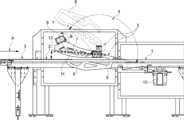
パネル2、3は、搬送方向に隣り合って配置された複数の部分ベルトを備える駆動されたコンベアベルト1(図1から6)上で、矢印Aの方向に搬送されている。製造上の理由のため、パネル2、3は、コンベアベルト1上で、一方が他方の後ろにあるペアとなっている。The
コンベアベルト1は、複数の離間した平行な個々のベルトからなる。回転装置4の部分回転装置は、各事例において、バンド間のフリースペースに配置されている。少なくとも2つの部分回転装置が、パネル2を取るために利用可能である。パネル2のパネル幅によれば、部分回転装置は、コンベアベルト1の個々のバンド間で異なる位置に配置可能である。好ましくは、部分回転装置間の距離は、変化することもできる。特に、部分回転装置は、コンベアベルト1の異なるベルト間に取り付け可能である。The
パネル3がコンベアベルト1上のこれらの位置のままである一方で、パネル2のみを回転装置4によって回転させることが提供される。It is provided that
回転装置4は、順に2つの脚部6、7(図7、8)を有する回転アーム5を有する。The
受け取り位置(図1)において下方に載置された脚部6は、回転ジョイント8を中心とした回転装置4の回転運動によって、その前端が可変位置に配置されるようにわずかに上向きに移動し、これにより、パネル2は、コンベアベルト1によって脚部6上に押し出され、その前端が脚部6上へとスライド可能となる。脚部6は、その表面上にコーティングが設けられ、これにより、パネル2は、十分に減速し、2つの脚部6、7が互いに接続された領域9に影響を及ぼさない。The
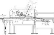
次に、パネル2は、ピボット8を中心とした回転矢印B方向における回転装置4のさらなる回転によって、その前端から持ち上げられ(図2)、これにより、好ましくは、パネル2の後端がパネル3の前端に対して載置される一方で、2つの脚部6、7間で上向きにスライドする。
回転装置4の回転運動は、接続ロッド11を駆動する駆動10によってもたらされ、これにより、偏心12を介して、回転ジョイント8を、位置8'(図2)に到達するように回転させる。同時に、回転装置4は、横方向運動を実行する。ここで、横方向運動は、フレーム13によって制限される。フレーム13は、パネル2の寸法に適合し、さらに、チェーン駆動または別の駆動が、好ましくは、回転装置4の横方向部分を実装するために存在する。回転装置の運動は、好ましくは、フレーム13に取り付けられた輪郭、例えば、湾曲した輪郭によって、またはカムディスクによって制限される。The rotational movement of the
パネル2は、ピボット8の回転運動によって押し上げられ、その後端でコンベアベルト1上に載置され続ける一方で、エリア9(図3、4)に向かって移動する。The
接続ロッド11の後退運動は、パネル2が脚部6、7間でセットアップされる(図4)一方で、回転装置4のピボット点を位置8''' '''にシフトする。The backward movement of the connecting
回転装置4をさらに回転させることによって、パネル2は、パネル3上に配置される(図5、6)。次に、接続ロッド11の運動によって、回転装置4の逆方向運動が完了し、これにより、これはその元の位置に戻り、別のパネル2を受け取る準備ができる。By further rotating the
回転アーム5は、少なくとも1つの連続的なボア14(図7、8)または追加の第2ボア15を有し、これにより、回転装置4の全ての回転アーム5は、接続ロッド15によって互いに接続される(図9)。回転アーム5は、フレーム20に取り付けられ、必要な場合、フレーム20において互いから異なる距離で配置される、例えば、互いに対してシフトされる。回転アーム5間の距離は可変なので、回転装置4は、異なるコンベア装置に容易に設置可能であり、コンベアベルト1のベルト17間で、異なる距離に適合可能である。The rotating
パネル2は、コンベアベルト1を介して回転装置4の回転アーム5に搬送され、これにより、パネル2は、回転アーム5が接続ロッド11を介して駆動10によってピックアップ位置に運び込まれたらすぐに、回転アーム5の脚部6および7の間で持ち上げられることができる。このように、矢印Aの方向に順に配置されるパネル2、3は、回転装置4による回転動作によって後続のパネル3上に配置された前方のパネル2によって重畳される。The
脚部6上にパネル2をスライドさせることは、好ましくは、脚部がその上面にローラ18、19を保持するという事実によって、容易にされる。あるいは、例えば、低滑り摩擦の材料で形成されたランナが脚部6上に設けられる。Sliding the
本発明は、このように、建材のパネルを連続的に回転させるためのマシンを形成する。The invention thus forms a machine for continuously rotating panels of building material.
Claims (15)
Translated fromJapanese前記回転装置は、回転運動および横方向運動の両方により前記複数のプレートを回転させるために使用される回転アームを有し、
前記回転運動の回転軸は、前記コンベアベルトの搬送方向と垂直であって、かつ、前記コンベアベルトの表面と平行であり、
前記横方向運動が、前記コンベアベルトの運動に平行な運動成分と、前記コンベアベルトの運動に垂直な運動成分とに分解され、
前記回転アームが、端部で互いに接続された第1脚部および第2脚部を有し、これらの間で前記複数のプレートの1つが前記第1脚部上にスライドすることにより、前記複数のプレートの前記1つを収容可能である、装置。 1. An apparatus for rotatinga plurality of plates by a rotating device,comprising: a conveyor belt for transportinga plurality of plates placed on the conveyor belt, the apparatus comprising:
the rotating devicehaving a rotating armthat is used to rotate the plurality of plates withbothrotational and lateral motion;
The rotation axis of the rotational motion is perpendicular to the conveying direction of the conveyor belt and parallel to the surface of the conveyor belt;
the lateral motion is resolved into a motion component parallel to the motion of the conveyor belt and a motion component perpendicular to the motion of the conveyor belt;
The apparatus, wherein the rotating arm has a first leg and a second leg connected to each other at an end, and is capable of accommodating one of the plurality of plates between them by sliding the one of the plurality of plates onto the first leg .
前記第1脚部は、前記第2脚部の前記長さの4分の3までの長さを有する、請求項1から8のいずれか一項に記載の装置。 the first leg is at least half as long as the second leg;or
9. The device of claim1, wherein the first leg has a length up to three-quarters of the length of the second leg .
前記複数のプレートが、第1プレートおよび第2プレートに分割され、各プレートが前記コンベアベルト上で、一方が他方の後ろに載置され、the plurality of plates are divided into a first plate and a second plate, each plate being placed one behind the other on the conveyor belt;
前記第1プレートが前記回転アームに把持され、回転させられ、The first plate is gripped by the rotating arm and rotated;
前記第1プレートが、前記コンベアベルト上または前記第2プレート上で、配置され、回転させられる、The first plate is positioned and rotated on the conveyor belt or on the second plate;
方法。method.
前記第1プレートは、前記回転アームの前記回転運動中に、前記回転アームの前記第1脚部から前記第2脚部上へと配置され、
前記回転アームの前記回転運動および前記横方向運動が完了した後、前記回転アームの前記第2脚部から前記第1プレートをスライドすることによって、前記第1プレートが前記第2プレート上に配置される、請求項11または12に記載の方法。the first plate is held by gravity between the first leg and the second leg of the rotating arm;
the first plateis disposed from the first leg onto the second leg of the rotating arm during the rotational movement of the rotating arm;
13. The method of claim 11 or 12, wherein after the rotational and lateral movements of the rotating arms are completed, the first plate is placed onto the second plate by sliding the first plate from the second leg of the rotating arm.
前記回転アームは、同時に前記横方向運動を行う一方で、前記スイベルジョイントを介してピボット可能である、請求項11から13のいずれか一項に記載の方法。14. The method of any one of claims 11 to 13, wherein the rotating arm is pivotable via the swivel joint while simultaneously performing the lateral movement.
Applications Claiming Priority (3)
| Application Number | Priority Date | Filing Date | Title |
|---|---|---|---|
| DE102020006799.9ADE102020006799A1 (en) | 2020-11-05 | 2020-11-05 | Device for turning panels |
| DE102020006799.9 | 2020-11-05 | ||
| PCT/EP2021/025429WO2022096150A1 (en) | 2020-11-05 | 2021-11-04 | Device for turning panels |
Publications (2)
| Publication Number | Publication Date |
|---|---|
| JP2023547500A JP2023547500A (en) | 2023-11-10 |
| JP7596609B2true JP7596609B2 (en) | 2024-12-10 |
Family
ID=78676540
Family Applications (1)
| Application Number | Title | Priority Date | Filing Date |
|---|---|---|---|
| JP2023526479AActiveJP7596609B2 (en) | 2020-11-05 | 2021-11-04 | Device for rotating panels |
Country Status (8)
| Country | Link |
|---|---|
| US (1) | US12286309B2 (en) |
| EP (1) | EP4240546A1 (en) |
| JP (1) | JP7596609B2 (en) |
| KR (1) | KR20230098843A (en) |
| CN (1) | CN116368085A (en) |
| CA (1) | CA3197346A1 (en) |
| DE (1) | DE102020006799A1 (en) |
| WO (1) | WO2022096150A1 (en) |
Families Citing this family (2)
| Publication number | Priority date | Publication date | Assignee | Title |
|---|---|---|---|---|
| CN117680553A (en)* | 2024-01-30 | 2024-03-12 | 四川省机械研究设计院(集团)有限公司 | Stamping structure and working method thereof |
| CN118162870A (en)* | 2024-04-16 | 2024-06-11 | 中国第一汽车股份有限公司 | Multi-vehicle type overturning driving mechanism and method |
Family Cites Families (24)
| Publication number | Priority date | Publication date | Assignee | Title |
|---|---|---|---|---|
| US2836282A (en) | 1957-02-18 | 1958-05-27 | Minnesota & Ontario Paper Co | Roof deck fabricating mechanism |
| DE1958785U (en) | 1967-02-03 | 1967-04-13 | Rudolf Grenzebach | TURNOVER WITH STAR-SHAPED REVERSING ARMS |
| GB1225774A (en) | 1967-05-25 | 1971-03-24 | ||
| DE2550321A1 (en) | 1975-11-08 | 1977-05-18 | Bayerische Motoren Werke Ag | Workpiece turning mechanism - has overlapping pockets on receiving end with pocket openings pointing in different directions |
| US4124126A (en)* | 1977-10-07 | 1978-11-07 | Carver Foundry Products | Roll-over mechanism |
| JPS58134233U (en)* | 1982-03-05 | 1983-09-09 | トヨタ自動車株式会社 | Work transfer device |
| US4484675A (en)* | 1982-12-13 | 1984-11-27 | U. S. Natural Resources, Inc. | Board turner apparatus and method capable of multiple turn inspection |
| JPH0522347Y2 (en) | 1987-03-31 | 1993-06-08 | ||
| US4798278A (en)* | 1987-07-23 | 1989-01-17 | General Machine Design, Inc. | Conveyor for turning packages upside down |
| DE3820523A1 (en) | 1988-05-03 | 1989-11-16 | Winkler Duennebier Kg Masch | DEVICE FOR TURNING CARTONES |
| US4947981A (en)* | 1989-04-13 | 1990-08-14 | Dorner Mfg. Corp. | Apparatus for inverting articles |
| US5605216A (en)* | 1994-12-30 | 1997-02-25 | Hi-Tech Engineering Inc. | Board turning apparatus |
| US5738483A (en)* | 1996-09-11 | 1998-04-14 | Giddings & Lewis, Inc. | Lift and invert mechanism |
| CN1332882A (en)* | 1998-12-18 | 2002-01-23 | 泰特斯工程发展(控股)有限公司 | vending machine |
| DE29905445U1 (en) | 1999-03-24 | 1999-11-11 | Steinbichler Optotechnik GmbH, 83115 Neubeuern | Turning device for turning a tire or the like. |
| CH695266A5 (en)* | 2002-04-03 | 2006-02-28 | Bobst Sa | Device for return of material cell sheet. |
| ATE361254T1 (en)* | 2002-12-03 | 2007-05-15 | Kauppila Richard W | DEVICE AND METHOD FOR TURNING AT HIGH SPEED |
| US20050150743A1 (en)* | 2004-01-08 | 2005-07-14 | Deane Henderson | Wane orientation board turner |
| AT503937B1 (en) | 2006-12-27 | 2008-02-15 | Voest Alpine Ind Anlagen | Turning-over metal slabs or plates of various thicknesses, employs swinging arms and rocker frame in iterative process securing firm parallel grip on plate |
| CN101754819B (en)* | 2007-07-20 | 2012-07-11 | Sms西马格股份公司 | Inspection system for rolled product and method for appraising surface of rolled product of rolling facility |
| AU2016353450B2 (en)* | 2015-11-13 | 2019-04-11 | Usnr, Llc | Board turner |
| DE102016111550A1 (en)* | 2016-06-23 | 2017-12-28 | Sms Group Gmbh | Cooling bed and turning method for turning on a cooling bed with a cross conveyor located, extending longitudinally workpieces |
| CN109719219A (en)* | 2017-10-31 | 2019-05-07 | 北京长征火箭装备科技有限公司 | A kind of automatic turning device with telescopic arms |
| CA3108237A1 (en)* | 2018-07-19 | 2020-01-23 | Claude Gravel | Rotative lumber piece charger for transferring and angularly orienting lumber pieces and method for performing same |
- 2020
- 2020-11-05DEDE102020006799.9Apatent/DE102020006799A1/enactivePending
- 2021
- 2021-11-04WOPCT/EP2021/025429patent/WO2022096150A1/ennot_activeCeased
- 2021-11-04CNCN202180074564.8Apatent/CN116368085A/enactivePending
- 2021-11-04EPEP21810285.3Apatent/EP4240546A1/enactivePending
- 2021-11-04KRKR1020237018744Apatent/KR20230098843A/enactivePending
- 2021-11-04CACA3197346Apatent/CA3197346A1/enactivePending
- 2021-11-04JPJP2023526479Apatent/JP7596609B2/enactiveActive
- 2021-11-04USUS18/035,379patent/US12286309B2/enactiveActive
Also Published As
| Publication number | Publication date |
|---|---|
| CN116368085A (en) | 2023-06-30 |
| US20240002166A1 (en) | 2024-01-04 |
| KR20230098843A (en) | 2023-07-04 |
| JP2023547500A (en) | 2023-11-10 |
| DE102020006799A1 (en) | 2022-05-05 |
| CA3197346A1 (en) | 2022-05-12 |
| WO2022096150A1 (en) | 2022-05-12 |
| EP4240546A1 (en) | 2023-09-13 |
| US12286309B2 (en) | 2025-04-29 |
Similar Documents
| Publication | Publication Date | Title |
|---|---|---|
| JP7596609B2 (en) | Device for rotating panels | |
| US7631744B2 (en) | Device for transporting printed products | |
| US4164996A (en) | Tile stacking machine and method | |
| US5450940A (en) | Delivery system for book-sewing machine | |
| WO1997008085A9 (en) | Stack turner and replenisher and method | |
| JP2001500826A (en) | Method and apparatus for packing flat articles | |
| JP4383573B2 (en) | Cutting machine for automatic cutting of printed matter such as temporary binding book, magazine or book | |
| JPH05338774A (en) | Flip sliding device | |
| JP2935526B2 (en) | Separation equipment for unbound stacking | |
| EP0711719A1 (en) | Equally spaced product conveying method and line | |
| JPH04216099A (en) | Bookbinding device for rounding bookbinding block | |
| KR0157283B1 (en) | Material transfer device | |
| US3789576A (en) | Wrapping apparatus with rotary horizontal lift | |
| EP0033799A1 (en) | Conveying apparatus for sheet-like articles | |
| EA047209B1 (en) | DEVICE FOR ROTTING PANELS | |
| CN209618106U (en) | Transfer device | |
| JPS63202555A (en) | Device for stacking flat article | |
| US3224307A (en) | Method and apparatus for handling sheet materials | |
| JP2558453B2 (en) | Device for adjusting the relative position of products and method for controlling the operation of the device | |
| JP3190047B2 (en) | Conveyor equipment | |
| JPH07241939A (en) | Folding case opening method and opening device | |
| JPH08217307A (en) | Bag delivery device | |
| US4238273A (en) | Rod applicator mechanism for machine for making hanging file folders | |
| JP3608023B2 (en) | Product receiving device for idle process | |
| US3724841A (en) | Sheet discharge mechanism |
Legal Events
| Date | Code | Title | Description |
|---|---|---|---|
| A521 | Request for written amendment filed | Free format text:JAPANESE INTERMEDIATE CODE: A523 Effective date:20230630 | |
| A621 | Written request for application examination | Free format text:JAPANESE INTERMEDIATE CODE: A621 Effective date:20230630 | |
| A131 | Notification of reasons for refusal | Free format text:JAPANESE INTERMEDIATE CODE: A131 Effective date:20240716 | |
| A521 | Request for written amendment filed | Free format text:JAPANESE INTERMEDIATE CODE: A523 Effective date:20241015 | |
| TRDD | Decision of grant or rejection written | ||
| A01 | Written decision to grant a patent or to grant a registration (utility model) | Free format text:JAPANESE INTERMEDIATE CODE: A01 Effective date:20241029 | |
| A61 | First payment of annual fees (during grant procedure) | Free format text:JAPANESE INTERMEDIATE CODE: A61 Effective date:20241030 | |
| R150 | Certificate of patent or registration of utility model | Ref document number:7596609 Country of ref document:JP Free format text:JAPANESE INTERMEDIATE CODE: R150 |