JP7593671B2 - Renewable power generation system and method - Google Patents
Renewable power generation system and methodDownload PDFInfo
- Publication number
- JP7593671B2 JP7593671B2JP2022554700AJP2022554700AJP7593671B2JP 7593671 B2JP7593671 B2JP 7593671B2JP 2022554700 AJP2022554700 AJP 2022554700AJP 2022554700 AJP2022554700 AJP 2022554700AJP 7593671 B2JP7593671 B2JP 7593671B2
- Authority
- JP
- Japan
- Prior art keywords
- temperature
- steam
- low
- working fluid
- renewable energy
- Prior art date
- Legal status (The legal status is an assumption and is not a legal conclusion. Google has not performed a legal analysis and makes no representation as to the accuracy of the status listed.)
- Active
Links
Images


Classifications
- F—MECHANICAL ENGINEERING; LIGHTING; HEATING; WEAPONS; BLASTING
- F03—MACHINES OR ENGINES FOR LIQUIDS; WIND, SPRING, OR WEIGHT MOTORS; PRODUCING MECHANICAL POWER OR A REACTIVE PROPULSIVE THRUST, NOT OTHERWISE PROVIDED FOR
- F03G—SPRING, WEIGHT, INERTIA OR LIKE MOTORS; MECHANICAL-POWER PRODUCING DEVICES OR MECHANISMS, NOT OTHERWISE PROVIDED FOR OR USING ENERGY SOURCES NOT OTHERWISE PROVIDED FOR
- F03G6/00—Devices for producing mechanical power from solar energy
- F03G6/06—Devices for producing mechanical power from solar energy with solar energy concentrating means
- F03G6/065—Devices for producing mechanical power from solar energy with solar energy concentrating means having a Rankine cycle
- F03G6/066—Devices for producing mechanical power from solar energy with solar energy concentrating means having a Rankine cycle of the Organic Rankine Cycle [ORC] type or the Kalina Cycle type
- F—MECHANICAL ENGINEERING; LIGHTING; HEATING; WEAPONS; BLASTING
- F01—MACHINES OR ENGINES IN GENERAL; ENGINE PLANTS IN GENERAL; STEAM ENGINES
- F01D—NON-POSITIVE DISPLACEMENT MACHINES OR ENGINES, e.g. STEAM TURBINES
- F01D15/00—Adaptations of machines or engines for special use; Combinations of engines with devices driven thereby
- F01D15/10—Adaptations for driving, or combinations with, electric generators
- F—MECHANICAL ENGINEERING; LIGHTING; HEATING; WEAPONS; BLASTING
- F01—MACHINES OR ENGINES IN GENERAL; ENGINE PLANTS IN GENERAL; STEAM ENGINES
- F01K—STEAM ENGINE PLANTS; STEAM ACCUMULATORS; ENGINE PLANTS NOT OTHERWISE PROVIDED FOR; ENGINES USING SPECIAL WORKING FLUIDS OR CYCLES
- F01K13/00—General layout or general methods of operation of complete plants
- F01K13/02—Controlling, e.g. stopping or starting
- F—MECHANICAL ENGINEERING; LIGHTING; HEATING; WEAPONS; BLASTING
- F01—MACHINES OR ENGINES IN GENERAL; ENGINE PLANTS IN GENERAL; STEAM ENGINES
- F01K—STEAM ENGINE PLANTS; STEAM ACCUMULATORS; ENGINE PLANTS NOT OTHERWISE PROVIDED FOR; ENGINES USING SPECIAL WORKING FLUIDS OR CYCLES
- F01K3/00—Plants characterised by the use of steam or heat accumulators, or intermediate steam heaters, therein
- F01K3/12—Plants characterised by the use of steam or heat accumulators, or intermediate steam heaters, therein having two or more accumulators
- F—MECHANICAL ENGINEERING; LIGHTING; HEATING; WEAPONS; BLASTING
- F01—MACHINES OR ENGINES IN GENERAL; ENGINE PLANTS IN GENERAL; STEAM ENGINES
- F01K—STEAM ENGINE PLANTS; STEAM ACCUMULATORS; ENGINE PLANTS NOT OTHERWISE PROVIDED FOR; ENGINES USING SPECIAL WORKING FLUIDS OR CYCLES
- F01K3/00—Plants characterised by the use of steam or heat accumulators, or intermediate steam heaters, therein
- F01K3/18—Plants characterised by the use of steam or heat accumulators, or intermediate steam heaters, therein having heaters
- F—MECHANICAL ENGINEERING; LIGHTING; HEATING; WEAPONS; BLASTING
- F03—MACHINES OR ENGINES FOR LIQUIDS; WIND, SPRING, OR WEIGHT MOTORS; PRODUCING MECHANICAL POWER OR A REACTIVE PROPULSIVE THRUST, NOT OTHERWISE PROVIDED FOR
- F03D—WIND MOTORS
- F03D9/00—Adaptations of wind motors for special use; Combinations of wind motors with apparatus driven thereby; Wind motors specially adapted for installation in particular locations
- F—MECHANICAL ENGINEERING; LIGHTING; HEATING; WEAPONS; BLASTING
- F03—MACHINES OR ENGINES FOR LIQUIDS; WIND, SPRING, OR WEIGHT MOTORS; PRODUCING MECHANICAL POWER OR A REACTIVE PROPULSIVE THRUST, NOT OTHERWISE PROVIDED FOR
- F03G—SPRING, WEIGHT, INERTIA OR LIKE MOTORS; MECHANICAL-POWER PRODUCING DEVICES OR MECHANISMS, NOT OTHERWISE PROVIDED FOR OR USING ENERGY SOURCES NOT OTHERWISE PROVIDED FOR
- F03G6/00—Devices for producing mechanical power from solar energy
- F03G6/06—Devices for producing mechanical power from solar energy with solar energy concentrating means
- F03G6/063—Tower concentrators
- F—MECHANICAL ENGINEERING; LIGHTING; HEATING; WEAPONS; BLASTING
- F03—MACHINES OR ENGINES FOR LIQUIDS; WIND, SPRING, OR WEIGHT MOTORS; PRODUCING MECHANICAL POWER OR A REACTIVE PROPULSIVE THRUST, NOT OTHERWISE PROVIDED FOR
- F03G—SPRING, WEIGHT, INERTIA OR LIKE MOTORS; MECHANICAL-POWER PRODUCING DEVICES OR MECHANISMS, NOT OTHERWISE PROVIDED FOR OR USING ENERGY SOURCES NOT OTHERWISE PROVIDED FOR
- F03G6/00—Devices for producing mechanical power from solar energy
- F03G6/06—Devices for producing mechanical power from solar energy with solar energy concentrating means
- F03G6/065—Devices for producing mechanical power from solar energy with solar energy concentrating means having a Rankine cycle
- F03G6/067—Binary cycle plants where the fluid from the solar collector heats the working fluid via a heat exchanger
- F—MECHANICAL ENGINEERING; LIGHTING; HEATING; WEAPONS; BLASTING
- F03—MACHINES OR ENGINES FOR LIQUIDS; WIND, SPRING, OR WEIGHT MOTORS; PRODUCING MECHANICAL POWER OR A REACTIVE PROPULSIVE THRUST, NOT OTHERWISE PROVIDED FOR
- F03G—SPRING, WEIGHT, INERTIA OR LIKE MOTORS; MECHANICAL-POWER PRODUCING DEVICES OR MECHANISMS, NOT OTHERWISE PROVIDED FOR OR USING ENERGY SOURCES NOT OTHERWISE PROVIDED FOR
- F03G6/00—Devices for producing mechanical power from solar energy
- F03G6/06—Devices for producing mechanical power from solar energy with solar energy concentrating means
- F03G6/068—Devices for producing mechanical power from solar energy with solar energy concentrating means having other power cycles, e.g. Stirling or transcritical, supercritical cycles; combined with other power sources, e.g. wind, gas or nuclear
- F—MECHANICAL ENGINEERING; LIGHTING; HEATING; WEAPONS; BLASTING
- F03—MACHINES OR ENGINES FOR LIQUIDS; WIND, SPRING, OR WEIGHT MOTORS; PRODUCING MECHANICAL POWER OR A REACTIVE PROPULSIVE THRUST, NOT OTHERWISE PROVIDED FOR
- F03G—SPRING, WEIGHT, INERTIA OR LIKE MOTORS; MECHANICAL-POWER PRODUCING DEVICES OR MECHANISMS, NOT OTHERWISE PROVIDED FOR OR USING ENERGY SOURCES NOT OTHERWISE PROVIDED FOR
- F03G6/00—Devices for producing mechanical power from solar energy
- F03G6/071—Devices for producing mechanical power from solar energy with energy storage devices
- F—MECHANICAL ENGINEERING; LIGHTING; HEATING; WEAPONS; BLASTING
- F22—STEAM GENERATION
- F22B—METHODS OF STEAM GENERATION; STEAM BOILERS
- F22B1/00—Methods of steam generation characterised by form of heating method
- F22B1/006—Methods of steam generation characterised by form of heating method using solar heat
- F—MECHANICAL ENGINEERING; LIGHTING; HEATING; WEAPONS; BLASTING
- F24—HEATING; RANGES; VENTILATING
- F24S—SOLAR HEAT COLLECTORS; SOLAR HEAT SYSTEMS
- F24S20/00—Solar heat collectors specially adapted for particular uses or environments
- F24S20/20—Solar heat collectors for receiving concentrated solar energy, e.g. receivers for solar power plants
- F—MECHANICAL ENGINEERING; LIGHTING; HEATING; WEAPONS; BLASTING
- F24—HEATING; RANGES; VENTILATING
- F24S—SOLAR HEAT COLLECTORS; SOLAR HEAT SYSTEMS
- F24S60/00—Arrangements for storing heat collected by solar heat collectors
- F24S60/30—Arrangements for storing heat collected by solar heat collectors storing heat in liquids
- F—MECHANICAL ENGINEERING; LIGHTING; HEATING; WEAPONS; BLASTING
- F24—HEATING; RANGES; VENTILATING
- F24S—SOLAR HEAT COLLECTORS; SOLAR HEAT SYSTEMS
- F24S80/00—Details, accessories or component parts of solar heat collectors not provided for in groups F24S10/00-F24S70/00
- F24S80/20—Working fluids specially adapted for solar heat collectors
- F—MECHANICAL ENGINEERING; LIGHTING; HEATING; WEAPONS; BLASTING
- F05—INDEXING SCHEMES RELATING TO ENGINES OR PUMPS IN VARIOUS SUBCLASSES OF CLASSES F01-F04
- F05B—INDEXING SCHEME RELATING TO WIND, SPRING, WEIGHT, INERTIA OR LIKE MOTORS, TO MACHINES OR ENGINES FOR LIQUIDS COVERED BY SUBCLASSES F03B, F03D AND F03G
- F05B2220/00—Application
- F05B2220/70—Application in combination with
- F05B2220/702—Application in combination with the other apparatus being a steam turbine
- F—MECHANICAL ENGINEERING; LIGHTING; HEATING; WEAPONS; BLASTING
- F05—INDEXING SCHEMES RELATING TO ENGINES OR PUMPS IN VARIOUS SUBCLASSES OF CLASSES F01-F04
- F05D—INDEXING SCHEME FOR ASPECTS RELATING TO NON-POSITIVE-DISPLACEMENT MACHINES OR ENGINES, GAS-TURBINES OR JET-PROPULSION PLANTS
- F05D2220/00—Application
- F05D2220/30—Application in turbines
- F05D2220/31—Application in turbines in steam turbines
- F—MECHANICAL ENGINEERING; LIGHTING; HEATING; WEAPONS; BLASTING
- F05—INDEXING SCHEMES RELATING TO ENGINES OR PUMPS IN VARIOUS SUBCLASSES OF CLASSES F01-F04
- F05D—INDEXING SCHEME FOR ASPECTS RELATING TO NON-POSITIVE-DISPLACEMENT MACHINES OR ENGINES, GAS-TURBINES OR JET-PROPULSION PLANTS
- F05D2220/00—Application
- F05D2220/70—Application in combination with
- F05D2220/76—Application in combination with an electrical generator
- Y—GENERAL TAGGING OF NEW TECHNOLOGICAL DEVELOPMENTS; GENERAL TAGGING OF CROSS-SECTIONAL TECHNOLOGIES SPANNING OVER SEVERAL SECTIONS OF THE IPC; TECHNICAL SUBJECTS COVERED BY FORMER USPC CROSS-REFERENCE ART COLLECTIONS [XRACs] AND DIGESTS
- Y02—TECHNOLOGIES OR APPLICATIONS FOR MITIGATION OR ADAPTATION AGAINST CLIMATE CHANGE
- Y02E—REDUCTION OF GREENHOUSE GAS [GHG] EMISSIONS, RELATED TO ENERGY GENERATION, TRANSMISSION OR DISTRIBUTION
- Y02E10/00—Energy generation through renewable energy sources
- Y02E10/40—Solar thermal energy, e.g. solar towers
- Y02E10/46—Conversion of thermal power into mechanical power, e.g. Rankine, Stirling or solar thermal engines
- Y—GENERAL TAGGING OF NEW TECHNOLOGICAL DEVELOPMENTS; GENERAL TAGGING OF CROSS-SECTIONAL TECHNOLOGIES SPANNING OVER SEVERAL SECTIONS OF THE IPC; TECHNICAL SUBJECTS COVERED BY FORMER USPC CROSS-REFERENCE ART COLLECTIONS [XRACs] AND DIGESTS
- Y02—TECHNOLOGIES OR APPLICATIONS FOR MITIGATION OR ADAPTATION AGAINST CLIMATE CHANGE
- Y02E—REDUCTION OF GREENHOUSE GAS [GHG] EMISSIONS, RELATED TO ENERGY GENERATION, TRANSMISSION OR DISTRIBUTION
- Y02E10/00—Energy generation through renewable energy sources
- Y02E10/70—Wind energy
- Y02E10/72—Wind turbines with rotation axis in wind direction
Landscapes
- Engineering & Computer Science (AREA)
- Chemical & Material Sciences (AREA)
- Combustion & Propulsion (AREA)
- Sustainable Energy (AREA)
- Life Sciences & Earth Sciences (AREA)
- Sustainable Development (AREA)
- Mechanical Engineering (AREA)
- General Engineering & Computer Science (AREA)
- Thermal Sciences (AREA)
- Physics & Mathematics (AREA)
- Power Engineering (AREA)
- Engine Equipment That Uses Special Cycles (AREA)
- Wind Motors (AREA)
- Diaphragms For Electromechanical Transducers (AREA)
Description
Translated fromJapanese本出願は、2020年3月8日付で出願された米国仮特許出願第62/987135号に対する優先権を主張し、その全体が本明細書に組み込まれる。This application claims priority to U.S. Provisional Patent Application No. 62/987,135, filed March 8, 2020, which is incorporated herein in its entirety.
本開示は、蒸気タービンなどの原動機(prime mover)を駆動するための高温の過熱蒸気を生成し、及び/又は熱、即ち高温熱を伝達するための再生エネルギーを使用するシステムに関し、再生可能エネルギーシステムの一部のみが高温の過熱蒸気を生成するのに必要な高温の作動流体に耐えられるように設計(designed)、エンジニアリング(engineered)、及び製造(fabricated)される必要がある。This disclosure relates to a system that uses renewable energy to generate high temperature superheated steam to drive a prime mover, such as a steam turbine, and/or to transfer heat, i.e., high temperature heat, where only a portion of the renewable energy system needs to be designed, engineered, and fabricated to withstand the high temperature working fluid required to generate the high temperature superheated steam.
蒸気タービンに動力を供給するための過熱蒸気を生成するため、CO2を加熱するため、又は発電機を駆動するための他の作動流体を加熱するため、及び/又は高温熱を提供するための再生可能エネルギーシステムについて説明する。これらのタイプのシステムは、特定の問題、即ち、蒸気タービンに高温の過熱蒸気を供給して(又は、このような異なる作動流体媒体を高温に加熱するために)全体再生可能システムが高温で動作することを必要とせず、どのようにタービンを最も効率的に作動するようにするかという問題に直面している。上述のように、本開示は、任意の作動流体又は媒体を高温に加熱することに関するものであり、本開示では、主に再生可能なエネルギーを使用して発電機を駆動する蒸気タービンを駆動するための過熱蒸気を生成することに焦点を当てており、システムの一部のみが過熱蒸気を生成するのに必要な高温に耐えるように設計及びエンジニアリングする必要がある。しかし、当業者は、本開示が熱伝達流体又は蓄熱媒体を高温に加熱するのに適用されることを理解すべきである。 Renewable energy systems are described for generating superheated steam to power a steam turbine, for heatingCO2 or other working fluids to drive a generator, and/or for providing high temperature heat. These types of systems face a particular problem: how to provide high temperature superheated steam to the steam turbine (or to heat such a different working fluid medium to a high temperature) to make the turbine operate most efficiently without requiring the entire renewable system to operate at high temperatures. As mentioned above, the present disclosure is concerned with heating any working fluid or medium to high temperatures, and the present disclosure focuses primarily on using renewable energy to generate superheated steam to drive a steam turbine that drives a generator, and only a portion of the system needs to be designed and engineered to withstand the high temperatures required to generate superheated steam. However, one skilled in the art should understand that the present disclosure applies to heating a heat transfer fluid or heat storage medium to high temperatures.
蒸気を過熱するには、通常、再生可能エネルギーシステム全体がこのような高温で動作する必要があり、例えば、再生可能システムによって供給されるエネルギーが大量の蒸気を過熱できるように、そのような高温に耐えられるに再生可能システムを設計する必要がある。従って、これは、再生可能エネルギーシステムとその構成要素(例えば、ポンプ、バルブ、配管など)を非常に高価な高温材料(Inconel(登録商標)合金又は他の高温合金又は材料)で作られる必要があった。タワー内の作動流体を加熱する反射鏡(例えば、ヘリオスタット)を備えた集光型太陽光発電(CSP、concentrated solar power)システムの場合、ヘリオスタットフィールドを非常に大きくする必要があり、過熱蒸気をタービンに供給するために、作動流体をタワー内で加熱する必要があり、例えば、630℃(1166°F)又はそれ以上の高温でシステムに配管接続される必要がある。そのような高温で過熱蒸気を生成するために、作動流体は、生成される過熱蒸気の温度よりも実質的に高い温度まで加熱されなければならず、十分な量のそのような高温の作動流体は、再生可能システムが太陽光発電システム(solar powered electrical generating system)の場合に夜間や曇りの日、又は再生可能システムが風力発電を使用して電気を生成する場合の風が吹かないときなど、長期間利用可能でなければならない。例えば、蒸気を過熱するために使用される作動流体は、過熱蒸気の所望の温度よりも十分に高く、非常に高い温度範囲で加熱及び貯蔵されることが好ましい場合がある。しかし、CSPシステムを使用して適切な作動流体をそのような高温に加熱する場合、これは、システム全体が高温の過熱蒸気を生成するのに必要な高温に耐えられるように設計及び製造される必要があるため、システムにかなりの工学設計上の問題及びコストの発生をもたらし、かなりのエンジニアリング及びコストの問題を賦課する。To superheat steam, the entire renewable energy system typically needs to operate at such high temperatures, e.g., the renewable energy system needs to be designed to withstand such high temperatures so that the energy provided by the renewable system can superheat a large amount of steam. This has therefore required the renewable energy system and its components (e.g., pumps, valves, piping, etc.) to be made of very expensive high-temperature materials (Inconel® alloys or other high-temperature alloys or materials). In the case of concentrated solar power (CSP) systems with reflectors (e.g., heliostats) that heat the working fluid in the tower, the heliostat field needs to be very large, and the working fluid needs to be heated in the tower to supply the superheated steam to the turbine, e.g., needs to be piped into the system at high temperatures of 630° C. (1166° F.) or higher. To generate superheated steam at such high temperatures, the working fluid must be heated to a temperature substantially higher than the temperature of the superheated steam to be generated, and sufficient amounts of such hot working fluid must be available for extended periods of time, such as at night or on cloudy days if the renewable system is a solar powered electrical generating system, or when the wind is not blowing if the renewable system uses wind power to generate electricity. For example, it may be preferable for the working fluid used to superheat the steam to be heated and stored at a very high temperature range, well above the desired temperature of the superheated steam. However, if a CSP system is used to heat a suitable working fluid to such high temperatures, this imposes significant engineering and cost challenges on the system, as the entire system must be designed and manufactured to withstand the high temperatures required to generate hot superheated steam.
CPSシステムによって生成された低/中熱を使用して低温/中温蒸気を生成し、次に別の区画化された再生可能エネルギーシステムを使用して低温/中温蒸気を所望の過熱状態に加熱する、再生可能なエネルギーを使用して蒸気タービンを駆動するシステムを有することは有利であることが認識された。例えば、この第2再生可能エネルギーシステムは、光電池(PV、photovoltaic)システム(又は、電気を生成する異なる再生可能エネルギーシステム)であって、PVシステムによって生成された電気の全部又は一部は、作動流体を、高温の作動流体が低温/中温蒸気を過熱し、過熱蒸気を蒸気タービンに送るために使用され、所望の高温まで局所的に加熱するために使用される。本開示によれば、この高温の作動流体は、第2再生可能エネルギーシステムによって生成された電気によって作動する電気加熱器によって電気的に加熱される高温貯蔵媒体によって加熱される伝熱ガスであり得る。このようにして、システム全体の一部のみを上述した高温で動作するように設計する必要がある。これにより、高温に対処するための高温材料の必要性が最小限に抑えられ、高温での熱損失が最小限に抑えらられる。It has been recognized that it is advantageous to have a system that uses renewable energy to drive a steam turbine, using low/medium heat generated by a CPS system to generate low/medium temperature steam, and then using another compartmentalized renewable energy system to heat the low/medium temperature steam to a desired superheated state. For example, this second renewable energy system can be a photovoltaic (PV) system (or a different renewable energy system that generates electricity), where all or a portion of the electricity generated by the PV system is used to locally heat a working fluid to a desired high temperature, where the high temperature working fluid superheats the low/medium temperature steam and sends the superheated steam to the steam turbine. In accordance with the present disclosure, this high temperature working fluid can be a heat transfer gas heated by a high temperature storage medium that is electrically heated by an electric heater powered by electricity generated by the second renewable energy system. In this way, only a portion of the entire system needs to be designed to operate at the above-mentioned high temperatures. This minimizes the need for high temperature materials to handle the high temperatures and minimizes heat losses at the high temperatures.
本開示は、最も簡単に言えば、集光型太陽光発電(CSP)システムなどの低温/中温蒸気を生成する、低温/中温再生可能エネルギーシステムであり、第1区画(compartment)又はブロックからの熱を使用する区画化された再生可能な発電システムである。本開示によれば、第2区画又はブロックは、電気エネルギーを生産する別の再生可能エネルギーシステムである。この第2区画又はブロックは、光電池(PV)システム、風力タービンシステム、水力発電システム、又は蓄電池バンクシステムなどの任意の再生可能な発電システムであり得る。この第2再生可能エネルギーシステムによって生成された電気エネルギー(又はそのような電気エネルギーの一部分)は、システム全体のごく一部のみを高温に加熱させる必要があるように、低温/中温システムによって生成された蒸気を過熱するのに使用される高温の作動流体の温度を上昇又は強化(即ち、加熱)するのに使用される。より具体的には、2次再生可能システムからの熱は、蓄熱媒体を加熱するために使用され、次に蒸気タービンを効率的に作動するのに必要な十分な量の過熱蒸気を生成するのに十分な高温まで第2作動流体を加熱するために使用される。蓄熱媒体の量は、夜間又は風が吹いていないときなど、第2再生可能な源(source)からのエネルギーが利用できないときに、高温の作動流体を連続的に加熱し続けて過熱蒸気を生成する量である。本開示のこの区画化されたシステムでは、2つの再生可能エネルギーシステムは、2つの再生可能エネルギーシステムが蒸気タービンに動力を供給するような蒸気タービンを含む第3区画又はブロックと呼ばれる共有又はメインパワーサイクルシステム(main power cycle system)に熱を提供する。このようにして、第1再生可能エネルギーシステムは、低/中温度の蒸気を作るために低/中熱を供給し、第2再生可能エネルギーシステム(例えば、PVシステム)は、低温/中温蒸気を過熱して蒸気タービンが効率的に作動するのに必要な過熱蒸気を供給するのに十分に高い温度で作動流体を供給する。The present disclosure is, in its simplest terms, a low/medium temperature renewable energy system that produces low/medium temperature steam, such as a concentrated solar power (CSP) system, and is a compartmentalized renewable power generation system that uses heat from a first compartment or block. According to the present disclosure, a second compartment or block is another renewable energy system that produces electrical energy. This second compartment or block can be any renewable power generation system, such as a photovoltaic (PV) system, a wind turbine system, a hydroelectric power generation system, or a battery bank system. The electrical energy (or a portion of such electrical energy) produced by this second renewable energy system is used to increase or enhance (i.e., heat) the temperature of a hot working fluid that is used to superheat the steam produced by the low/medium temperature system, such that only a small portion of the entire system needs to be heated to a high temperature. More specifically, the heat from the secondary renewable system is used to heat a thermal storage medium, which is then used to heat the second working fluid to a high enough temperature to produce a sufficient amount of superheated steam required to efficiently operate a steam turbine. The amount of thermal storage medium is such that the hot working fluid continues to be heated continuously to produce superheated steam when energy from the second renewable source is not available, such as at night or when the wind is not blowing. In this compartmentalized system of the present disclosure, the two renewable energy systems provide heat to a shared or main power cycle system, called a third compartment or block, that includes a steam turbine in which the two renewable energy systems power the steam turbine. In this way, the first renewable energy system provides low/medium heat to make low/medium temperature steam, and the second renewable energy system (e.g., PV system) provides a working fluid at a high enough temperature to superheat the low/medium temperature steam to provide the superheated steam required for the steam turbine to operate efficiently.
また、本開示によれば、第2再生可能エネルギーシステムの一部のみが蒸気タービンに供給される低温/中温蒸気を過熱するのに必要な高温の作動流体を供給するのに要求される高温に耐えられるようにエンジニアリング(engineered)される必要がある。従って、この区画化されたシステムは、他のシステムよりも設備及び構築のコストがはるかに低くなる。第1及び第2再生可能エネルギーシステムの両方は、夜間、曇りの日、又は風が吹かないときなどの再生可能エネルギーシステムが利用できない場合など、長時間にわたって(例えば、8~12時間以上)発電システムの蒸気タービンに電力を供給するのに十分な蓄熱能力を有する必要がある。Also, according to the present disclosure, only a portion of the second renewable energy system needs to be engineered to withstand the high temperatures required to provide the hot working fluid necessary to superheat the low/medium temperature steam supplied to the steam turbine. Thus, this compartmentalized system is much less expensive to equip and build than other systems. Both the first and second renewable energy systems need to have sufficient thermal storage capacity to power the steam turbine of the power generation system for extended periods of time (e.g., 8-12 hours or more), such as during times when the renewable energy systems are unavailable, such as at night, on cloudy days, or when the wind is not blowing.
より具体的には、本開示の好ましい実施形態は、第3ブロック、即ち発電機を駆動する蒸気タービンなどのパワーシステムに電力を供給する区画化された再生可能な発電システムを説明する。この好ましい実施形態では、低温/中温集光型太陽光発電(CSP)システムなどの第1再生可能エネルギーシステムから又はこれによって収集された熱は、溶融塩などの第1又は低温/中温の作動流体を加熱し、CSPシステムからの熱は、溶融塩作動流体を介したエネルギー貯蔵を組み込んでいる。貯蔵された第1又は低温/中温の作動流体の量は、太陽が照らさない悪天候又は夜間など、第1再生可能エネルギーシステムが効果的に作動しない長時間の間、低温/中温蒸気を生成するのに十分である。この低温/中温再生可能システムからの熱は、第2又は高温の作動流体(例えば、伝熱ガス)を加熱する第2又は高温再生可能エネルギーシステムによって上昇又は強化され、第2再生可能エネルギーシステムの一部のみが蒸気タービンに過熱蒸気を供給するのに必要な高温に耐えられるように設計及び構成される必要がある。第2又は高温再生可能エネルギーシステムは、好ましくは、光電池(PV)発電システム(electricity generation system)、風力発電システム、水力発電システム、電池バックアップ蓄電システムなどの電気を生成するシステムである。第2再生可能エネルギーシステムからの電気は、電気抵抗加熱器などの蓄熱媒体を介して非常に高い温度に加熱する。蓄熱媒体は、必須ではないが、好ましくは溶融金属又は半金属の相変化を利用して高温の熱を蓄える融解潜熱蓄熱システムであることが好ましい。しかし、本開示のより広い態様では、コンクリート、砂、岩石、又はセラミック材料の塊など、相を変化させない蓄熱媒体が使用され得る。伝熱ガスは、低温/中温蒸気を過熱するのに十分な高温に加熱されるように、蓄熱媒体と熱交換関係で循環する。加熱された蓄熱媒体の熱容量は、悪天候、及び/又は太陽が照らさない、夜間、又は風が吹かない場合など、第2再生可能エネルギーシステムが利用できないとき、そのような過熱蒸気を生成するためのシステムを作動させるのに十分である。従って、2つの再生可能エネルギーシステムは、蒸気タービンに過熱蒸気を供給するために熱を提供する。重要なことは、本開示によれば、蓄熱媒体を加熱して貯蔵する第2再生可能エネルギーシステムの一部と、高温の伝熱ガスを過熱器に供給する第2システムの一部のみが高温蓄熱媒体及び伝熱ガスの高温に耐えられるようにエンジニアリングして構成される必要がある。More specifically, a preferred embodiment of the present disclosure describes a compartmentalized renewable power generation system that supplies power to a third block, i.e., a power system such as a steam turbine that drives a generator. In this preferred embodiment, heat collected from or by a first renewable energy system, such as a low/medium temperature concentrating solar power (CSP) system, heats a first or low/medium temperature working fluid, such as molten salt, and the heat from the CSP system incorporates energy storage via the molten salt working fluid. The amount of stored first or low/medium temperature working fluid is sufficient to generate low/medium temperature steam during extended periods when the first renewable energy system does not operate effectively, such as during bad weather or at night when the sun is not shining. The heat from this low/medium temperature renewable system is augmented or enhanced by a second or high temperature renewable energy system that heats a second or high temperature working fluid (e.g., a heat transfer gas), and only a portion of the second renewable energy system needs to be designed and configured to withstand the high temperatures required to supply superheated steam to the steam turbine. The second or high temperature renewable energy system is preferably a system that generates electricity, such as a photovoltaic (PV) electricity generation system, a wind power generation system, a hydroelectric power generation system, a battery backup storage system, etc. Electricity from the second renewable energy system is heated to a very high temperature via a heat storage medium, such as an electric resistance heater. The heat storage medium is preferably, but not necessarily, a molten latent heat storage system that uses a phase change of a molten metal or metalloid to store high temperature heat. However, in broader aspects of the present disclosure, a heat storage medium that does not change phase, such as concrete, sand, rock, or a mass of ceramic material, may be used. A heat transfer gas circulates in a heat exchange relationship with the heat storage medium so that the gas is heated to a high enough temperature to superheat the low/medium temperature steam. The heat capacity of the heated heat storage medium is sufficient to operate the system for generating such superheated steam when the second renewable energy system is unavailable, such as in bad weather and/or when the sun is not shining, at night, or when the wind is not blowing. Thus, the two renewable energy systems provide heat to supply superheated steam to the steam turbine. Importantly, according to the present disclosure, only the portion of the second renewable energy system that heats and stores the heat storage medium and the portion of the second system that supplies the hot heat transfer gas to the superheater need to be engineered and configured to withstand the high temperatures of the hot heat storage medium and the heat transfer gas.
前述のように、その好ましい実施形態における本開示は、集光型太陽光発電(CSP)システムなどの第1又は低温/中温再生可能エネルギーシステムからの熱を利用する、区画化又はセグメント化された再生可能な電力及び/又は熱生成システム及び方法である。この第1再生可能エネルギーシステムからのエネルギーは、溶融塩などの第1作動流体によって、適切な貯蔵タンクなどに貯蔵される。この相対的に低温/中温の熱は、低温/中温蒸気を生成するのに使用される。光電池(PV)発電システムなどの第2再生可能エネルギーシステムからの高温熱は、低温/中温蒸気を設定された共通の動力サイクルで蒸気タービン/発電機に供給される過熱蒸気に上昇させるのに使用される。従って、第2再生可能エネルギーシステムの一部のみを高温材料及び構成要素を有するようにエンジニアリングする必要があるため、システム全体のコストが大きく節減できる。本開示のシステムの好ましい実施形態では、第2再生可能エネルギーシステム(例えば、光電池(PV)システム)によって生成された電気の一部又は全部を使用して電気を生成することができ、このエネルギーの一部を使用して金属又は半金属を溶融するように蓄熱媒体を加熱し、高温エネルギー(溶融金属又は溶融半金属からの融解潜熱の形態で)が貯蔵タンク又は容器に適切な温度で貯蔵されるようにする。蓄熱媒体からの熱は、伝熱ガスを高温に加熱するのに使用され、これは、順に過熱器などに供給され、第1再生可能エネルギーシステムによって生成された低温/中温蒸気を過熱する。従って、これらの2つの再生可能エネルギーシステムは、共通蒸気パワーサイクルで蒸気を形成して過熱するために熱を提供するために使用され、2つの再生可能システムのエネルギー貯蔵容量は、夜間や風が吹かないような再生可能エネルギーシステム又は源からのエネルギーを直接利用できない場合に、長時間にわたって共通蒸気パワーサイクルで予想される電力を提供するのに十分である。本開示の再生可能なエネルギープラントの新規の区画化は、適切な再生工程の組み合わせを使用して、中温/低温蒸気を独立的に生成し、これを共通蒸気パワーサイクル又はシステムで蒸気タービンを駆動するために所望の高温まで過熱する。As previously mentioned, the present disclosure in its preferred embodiments is a compartmentalized or segmented renewable power and/or heat generation system and method that utilizes heat from a first or low/medium temperature renewable energy system, such as a concentrated solar power (CSP) system. The energy from this first renewable energy system is stored, such as in a suitable storage tank, with a first working fluid, such as molten salt. This relatively low/medium temperature heat is used to generate low/medium temperature steam. High temperature heat from a second renewable energy system, such as a photovoltaic (PV) power generation system, is used to raise the low/medium temperature steam to superheated steam that is fed to a steam turbine/generator in a set common power cycle. Thus, significant savings in the overall system cost are achieved since only a portion of the second renewable energy system needs to be engineered to have high temperature materials and components. In a preferred embodiment of the system of the present disclosure, some or all of the electricity generated by the second renewable energy system (e.g., a photovoltaic (PV) system) can be used to generate electricity, and some of this energy is used to heat a heat storage medium to melt the metal or metalloid, such that high temperature energy (in the form of latent heat of fusion from the molten metal or metalloid) is stored at a suitable temperature in a storage tank or vessel. The heat from the heat storage medium is used to heat a heat transfer gas to a high temperature, which in turn is fed to a superheater or the like to superheat the low/medium temperature steam generated by the first renewable energy system. Thus, these two renewable energy systems are used to provide heat to form and superheat steam in a common steam power cycle, and the energy storage capacity of the two renewable systems is sufficient to provide the expected power of the common steam power cycle for an extended period of time when energy from the renewable energy systems or sources is not directly available, such as at night or when the wind is not blowing. The novel compartmentalization of the disclosed renewable energy plant uses a combination of appropriate regenerative processes to independently generate intermediate/low temperature steam, which is superheated to the desired high temperature to drive steam turbines in a common steam power cycle or system.
例えば、例示の目的において、CSPシステムなどの第1又は低温/中温再生可能エネルギーシステムは、例えば、470℃(878°F)までの低温/中温蒸気を生成するのに使用されてもよい。高温の過熱蒸気を作るために必要な残りの熱は、PVシステム又は電気を生成する他の再生可能システムなど、第2又は高温の再生可能エネルギーシステムから得られる。第2再生可能エネルギーシステムによって生成される電気の全部又は一部は、第2又は高温の作動流体(例えば、高温伝熱ガス)を加熱するのに使用され、第2再生可能エネルギーシステムの一部のみが非常に高い温度(例えば、1,500℃(約2,732°F)まで)で動作するように設計及び構成され、発電の全体的なコストを最小限に抑えながら、最大の効率と柔軟性を提供する。For example, and by way of illustration, a first or low/medium temperature renewable energy system, such as a CSP system, may be used to generate low/medium temperature steam, e.g., up to 470°C (878°F). The remaining heat required to create the high temperature superheated steam is obtained from a second or high temperature renewable energy system, such as a PV system or other renewable system that generates electricity. All or a portion of the electricity generated by the second renewable energy system is used to heat a second or high temperature working fluid (e.g., a high temperature heat transfer gas), with only a portion of the second renewable energy system designed and configured to operate at very high temperatures (e.g., up to 1,500°C (about 2,732°F)), providing maximum efficiency and flexibility while minimizing the overall cost of power generation.
本開示の他の態様、目的、及び特徴は、以下に部分的に開示され、当業者には明らかである。Other aspects, objects, and features of the present disclosure are disclosed in part below and will be apparent to those skilled in the art.
対応する参照符号は、図面全体にわたって対応する部分を示す。Corresponding reference characters indicate corresponding parts throughout the drawings.
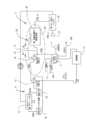
図1に示すように、本開示の区画化又はセグメント化されたシステムは、全体が1で示される。この区画化されたシステムは、一般に3で示され、ブロックCに示されるように、主(又は1次)蒸気動力発電システムを含む。高温の過熱蒸気が蒸気タービン5(原動機)に供給され、次に発電機7を駆動する。過熱蒸気は、一般に9で示される(ブロックAに示される)ように第1又は低温/中温再生可能エネルギーシステムによって部分的に生成され、部分的には、一般に11で示される(ブロックBに示される)ように第2又は高温再生可能エネルギーシステムによって生成される。第1又は低温/中温再生可能エネルギーシステム9は、蒸気タービン5に伝達される高温の過熱蒸気を形成するために、第2又は高温再生可能エネルギーシステム11によって加熱される低温/中温蒸気を生成する。As shown in FIG. 1, the compartmentalized or segmented system of the present disclosure is generally designated 1. The compartmentalized system includes a main (or primary) steam powered generation system, generally designated 3, as shown in Block C. High temperature superheated steam is provided to a steam turbine 5 (prime mover), which in turn drives a
より具体的には、蒸気タービン5及び発電機7に加えて、主又は1次蒸気動力発電システム3は、蒸気タービン5から低温蒸気及び/又は凝縮液(condensate)を受け取る凝縮器(condenser)13を含む。凝縮器13を出た液体給水は、ポンプ17を介して低温/中温エコノマイザ/蒸発器15に供給される。以下で詳細に説明するように、第1又は低温/中温再生可能エネルギーシステム9からの比較的に低温/中温の熱は、エコノマイザ/蒸発器15の給水を加熱して、低温/中温蒸気(例えば、約60℃又は860°F)を形成し、以後再熱器/過熱器19に供給されて第2又は高温再生可能エネルギーシステム11の高温部分20(以下に説明)によって比較的に高温(例えば、約630℃又は1166°F)で再加熱及び過熱される。過熱器に供給される伝熱ガスは、例えば、十分に高い温度(例えば、約800℃~1100℃(1472°F~2012°F))で加熱され、エコノマイザ/蒸発器15からの低温/中温蒸気を過熱して過熱蒸気をタービン5に供給し、タービンが最も効率的に稼動するようにする。第1再生可能エネルギーシステム9の全体が低温/中温で稼動し、全ての構成要素及び配管が低温/中温材料で製造され得ることに特に留意されたい。重要なことは、第2再生可能エネルギーシステム11の高温部分20のみが高温で稼動することである。これは、高温部分20の構成要素だけを第2再生可能エネルギーシステムの構築及び運用コストを低減する高温材料で、設計、エンジニアリング、及び構成する必要があることを意味する。これにより、第1再生可能エネルギーシステム及び第2再生可能エネルギーシステムの両方のコストを抑えることができる。本明細書で使用される「配管」という用語は、パイプ(pipe)に限定されず、ダクト(duct)、ライン(line)、管路(conduit)、チャネル(channel)、チューブ(tube)、及び作動流体を輸送できる他の構造を含み、これらは当業者によって理解される。また、低温/中温蒸気が再熱器/過熱器19で再加熱及び過熱されるが、本開示のより広い態様では、蒸気タービンによっては低温/中温蒸気を再加熱する必要がない場合もあり、過熱器だけが必要になる。More specifically, in addition to the
図1に示すように、第1又は低温/中温再生可能エネルギーシステム9は、好ましくは、例えば、第1作動流体を約470℃又は878°Fなどの低温/中温に加熱するように、タワーの上端部にあるレシーバ21で態様光を反射するように制御される複数のヘリオスタット(図示されていないが、当業者には良く知られている)を使用する減少した温度集光型太陽光発電(CSP)システムである。この第1作動流体は、例えば、レシーバを介して循環して加熱されるCSPシステムとして周知かつ広く使用されている溶融塩であり得る。太陽が照らしている昼間にかけて、レシーバによって低温/中温(例えば、470℃又は878°F)に加熱された溶融塩は、温タンク23(又は他の適切な貯蔵容器又はリザーバ)に貯蔵される。太陽が照らしている又は照らしていない昼間、又は夜間に、このような低温/中温(例えば、470℃)で貯蔵された溶融塩は、ポンプ17によって供給された給水を加熱及び蒸発させて、低温/中温蒸気(例えば、約460℃又は860°F)を形成するために、温タンク23から回収されてエコノマイザ/蒸発器15に供給されてもよい。エコノマイザ/蒸発器15を通過した溶融塩は、冷タンク25に低温(例えば、約290℃又は554°F)で貯蔵され、この低温は、塩を溶融状態に保持するのに十分である。温タンク23に貯蔵された溶融塩の量は、例えば、太陽が低温/中温エネルギーをエコノマイザ/蒸発器15に直接供給できる昼間及び夜間や悪天候のように長時間にわたり太陽が照らさないときの両方において、エコノマイザ/蒸発器15に低温/中温エネルギーを供給するのに十分である。当業者は、システムが、太陽が照らさないとき及び/又は夜間に作動するように設計されている時間の長さに応じて、温タンク23が、より多くの又はより少ない量のそのような低温/中温の溶融塩を保持するようにサイズ設定され得ることを認識するであろう。低温/中温の溶融塩がエコノマイザ/蒸発器15で蒸気を生成した後、例えば、約290℃(554°F)であり得る、現在より低温の溶融塩は冷タンク25に貯蔵される。太陽が照らしているとき、相対的に冷たいが、依然として溶融されている冷タンク25の塩はレシーバ21に供給され、所望の高温(例えば、約470℃、878°F)で再加熱され、温タンク23に貯蔵されてもよい。当業者は、第1再生可能エネルギーシステム9が上述のヘリオスタットシステムであってもよく、又はトラフリフレクタ太陽光システムであってもよく、他のタイプの太陽光熱収集システムであってもよく、又は地熱作動流体加熱システムが使用されてもよく、又は任意の他の再生可能な熱源が使用されてもよいことを理解するであろう。もちろん、タンク23,25は、適切な断熱材で断熱されることが好ましい。As shown in FIG. 1, the first or low/medium temperature
ブロックBに示すように、第2又は高温再生可能エネルギーシステム11は、好ましくは光電池(PV)システムなどの再生可能なエネルギー発電システムを含む。しかし、風力タービン発電機、水力発電システム、又は蓄電池システムなどの他のタイプの再生可能なエネルギー発電システムが光電池システムの代わりに使用されてもよい。図1に示される光電池(PV)システム11の場合、複数の適切なPV太陽光パネル(図1に示されていないが、技術分野では周知である)が配置され、太陽光を受け取り、太陽光を電気に変換する。もちろん、このようなシステムの問題点は、曇りの日や夜間など、太陽が照らさないときに動作するための電気を大量に容易に貯蔵することができないことである。第2再生可能エネルギーシステム11では、PV再生可能なエネルギー電気システムによって生成された電気の全部又は一部のみがエネルギーグリッド27に直接供給されることができ、及び/又は生成された電気の一部が30に示すように大量の適切な高温蓄熱媒体を含む蓄熱タンク29(又は他の適切な貯蔵容器又はリザーバ)内に配置される電力電気加熱器28で使用されてもよい。好ましい実施形態では、この高温蓄熱媒体30は、加熱器によって溶融され、蓄熱タンク内で溶融状態に保持される金属又は半金属である。しかし、本開示のより広い態様では、蓄熱媒体は、溶融金属又は半金属である必要はなく、砂、岩石、コンクリート、又はセラミック材料などの固体蓄熱材料の量又は塊であってもよい。このような固体蓄熱材料は、溶融シリコンなどの半金属の相対的に高温ではないこともあるが、依然として作動流体を蒸気タービン5に供給される蒸気を過熱するのに必要な温度まで加熱するのに十分な熱容量を有する。高温であることに加えて、溶融シリコン蓄熱材料は、販売される蓄熱材料よりも小さな質量と小さなフットプリントを必要とする場合がある。As shown in block B, the second or high temperature
第2再生可能エネルギーシステム11では、例えば、生成された電気の約75%は、エネルギーグリッド27に直接供給することができ、残りの25%は、蓄熱媒体が溶融金属又は溶融半金属であるか、又は砂、岩石、コンクリート、又はセラミックなどの固体蓄熱材料であるかに関わらず、タンク又はリザーバ29内の蓄熱材料30を加熱し、その温度を所望のレベルに保持するため、加熱器28に電力を供給するため使用され得る。もちろん、これらのパーセンテージは、100%がエネルギーグリッドに供給される場合と、100%が電気加熱器に電力を供給するために使用される場合との間で変化し得る。当業者は、電気加熱器28が、電気抵抗加熱器、誘導コイル、電気アーク炉に使用される電気アーク加熱器、マイクロ波加熱器、又は技術分野で公知の他の適切な電気加熱器であり得ることを理解するであろう。In the second
本開示によれば、タンク29内の高温蓄熱材料30は、温タンク23内の溶融塩の温度よりもはるかに高温に加熱され、高温蓄熱材料が第2作動流体(高温伝熱ガス)を蒸気タービン5に供給される低温/中温蒸気を過熱するのに十分な高い温度(例えば、約800℃~1100℃(1472°F~2012°F))まで上昇させる。例えば、タンク29内の高温蓄熱材料は約1,000℃(1832°F)から約1,500℃(2,732°F)の範囲に加熱することができる。従って、伝熱ガスは、所望の温度で過熱蒸気が蒸気タービン5に供給されるように、再加熱器/過熱器19内の低温/中温蒸気を過熱するのに十分な温度まで蓄熱タンク29内の蓄熱媒体によって加熱される。この高温伝熱ガスは、供給ライン31を介して再加熱器/過熱器19に供給され、蒸発器15からの低温/中温蒸気を過熱し、過熱蒸気を蒸気タービン5に十分な量及び所望の高温で供給して蒸気タービンが効率的に稼動するようにする。タンク29内の蓄熱媒体は、十分に高い熱容量及び体積を有し、太陽が照らさない夜間などの長時間にわたって、蒸気タービン5に過熱蒸気を供給するのに十分な高温である。本開示において、用語「半金属」という用語は、一部金属及び一部非金属の特性を示す化学元素又は他の物質を意味するものと定義される。According to the present disclosure, the high temperature
上述のように、好ましい高温蓄熱材料は、好ましくは溶融金属又は半金属であり得る。本開示のより広い態様では、溶融金属又は半金属のいくつかの一般的な例には、ナトリウム、スズ、鉛などの金属又は半金属、又は鉛ビスマス共晶(lead bismuth eutectic)又はLBEなどのそれらの合金又は、ホウ素(boron)、シリコン(silicon)、ゲルマニウム(germanium)、ヒ素(arsenic)、アンチモン(antimony)、テルリウム(tellurium)、ポロニウム(polonium)などの半金属であり得るが、これらに限定されない。特に、好ましい高温蓄熱材料は、溶融シリコンである。上述のように、本開示のより広い態様において、熱伝達媒体は、溶融金属又は半金属である必要はなく、むしろ電気加熱器28によって高温に加熱され、タンク又はリザーバ29に貯蔵された砂、岩石、コンクリート、又はセラミック材料の塊であり得る。As mentioned above, the preferred high temperature heat storage material may preferably be a molten metal or metalloid. In the broader aspects of the present disclosure, some common examples of molten metals or metalloids may include, but are not limited to, metals or metalloids such as sodium, tin, lead, or alloys thereof such as lead bismuth eutectic or LBE, or metalloids such as boron, silicon, germanium, arsenic, antimony, tellurium, polonium, etc. In particular, the preferred high temperature heat storage material is molten silicon. As mentioned above, in the broader aspects of the present disclosure, the heat transfer medium need not be a molten metal or metalloid, but rather may be a mass of sand, rock, concrete, or ceramic material heated to a high temperature by an
本開示によれば、高温熱伝達作動流体は、好ましくは、空気、窒素、CO2、又は不活性ガスなどの伝熱ガスであり、内部にある蓄熱材料によって加熱される貯蔵タンク29内の蓄熱材料と熱伝達関係にあるように循環する。次に、加熱された伝熱ガスは、再熱器/過熱器19を介して流れ、エコノマイザ/蒸発器15からの低温/中温蒸気を過熱する。伝熱ガスは、必須ではないが、好ましくは、比較的低圧で、例えば、約20~40インチの水柱によって加圧されるが、当業者であれば、このガスが正圧又は真空の任意の所望の圧力に加圧され得ることを理解するであろう。適切な高温送風機又はポンプ(図1には図示せず)は、蓄熱タンク29内の高温蓄熱媒体30と熱伝達関係にあるように、伝熱ガスを循環させるのに使用される。伝熱ガスは、蒸気タービン5に供給されるエコノマイザ/蒸発器15からの低温/中温蒸気を過熱するのに十分に高い温度及び十分な量で、再熱器/過熱器19に供給される。伝熱ガスは、タンク29内の蓄熱材料によって再び加熱されるために、戻りライン33を介してタンク29に戻される。このように、第2再生可能エネルギーシステム11の高温部分20のみが、タンク29内の高温蓄熱材料の高温に耐えられるように設計され、高温材料で構築される必要があることが理解されるであろう。具体的には、高温部分20は、タンク29、タンク29内の加熱器28、及びタンク29から再熱器/過熱器19に高温伝熱ガスを循環させる供給配管31を含む。再熱器/過熱器19の構築(construction)及び稼働(operation)により、後者は、エコノマイザ/蒸発器15から流入する低温/中温蒸気によって事実上冷却されるため、このような高温材料で構築する必要はないこともある。同様に、戻りライン33は、高温材料で構成される必要がない。また、このような伝熱ガスを使用することにより、シャットダウンが長引いた場合に、第2再生可能エネルギーシステムの高温部分20で伝熱ガスが「凍結」する危険がないことも理解されるであろう。 In accordance with the present disclosure, the hot heat transfer working fluid is preferably a heat transfer gas such as air, nitrogen, CO2 , or an inert gas, which circulates in heat transfer relationship with the heat storage material in the
必須ではないが、好ましくは、蓄熱媒体は溶融シリコン(Si)である。シリコンの融点は、1,414℃(2,577°F)であり、沸点は、2,355℃(4,270°F)であるため、溶融状態の温度範囲が広くなる。本開示によれば、融点を超える溶融シリコンのいくらかの顕熱(sensible heating)が存在する可能性があるが、この可能な顕熱による追加的な蓄熱は、典型的には、後述するように金属又は半金属の融解潜熱による蓄熱と比較したとき、比較的に小さい。伝熱ガスがタンク29内の溶融シリコンによって長時間加熱されると、シリコンの温度は、シリコンの凝固を引き起こすことなく、凝固点まで低下し得ることが理解されるであろう。これは、シリコンの大きな潜熱容量によるものである。また、溶融シリコンが酸素及び他の材料と化学的に反応することも認識されている。そのため、タンク29は、窒素などの非酸化性ガス、又はヘリウム又はアルゴンなどの不活性ガスで封止及び/又は満たされ、内部の溶融金属又は半金属が大気にさらされないようにすることが好ましい。また、伝熱ガスは、溶融蓄熱媒体の酸化又はその他の化学的劣化を低減するように、タンク29内の溶融金属又は半金属の蓄熱媒体と直接接触しないことが好ましい。もちろん、岩石、砂、コンクリート、又はセラミック材料などの固体の蓄熱媒体を使用する場合、酸化は問題にならない場合がある。Preferably, but not necessarily, the heat storage medium is molten silicon (Si). Silicon has a melting point of 1,414°C (2,577°F) and a boiling point of 2,355°C (4,270°F), resulting in a wide temperature range in the molten state. According to the present disclosure, there may be some sensible heating of the molten silicon above the melting point, but this possible additional heat storage is typically relatively small when compared to the heat storage due to the latent heat of fusion of metals or metalloids, as described below. It will be appreciated that if the heat transfer gas is heated for an extended period of time by the molten silicon in the
「融解潜熱」は、固体から液体に変化するために、融点まで加熱された材料の固体に供給されなければならない熱量である。材料の非潜熱(L)は、相変化中に放出又は吸収される単位質量(m)当たりの熱エネルギー(Q)の尺度であり、材料の融解潜熱と呼ばれ、通常、ジュール/モル[J/mol]として、SI単位で表される。シリコンの溶融温度は約1414℃(2577°F)であり、シリコンの融解潜熱は50.55kJ/molであり、シリコンの気化潜熱は384.22kJ/molである。重要なことは、シリコンの融解熱(50.55kJ/mol)は、液体状態で貯蔵され得る他の金属に比べて非常に大きいことである。例えば、鉛(pb)の融解熱は4.799kJ/molであり、スズ(Sn)の融解潜熱は7.322kJ/molである。物質の特定の質量の潜熱は、Q=m×Lで算出される。"Latent heat of fusion" is the amount of heat that must be supplied to a solid of a material heated to its melting point in order to change from a solid to a liquid. The non-latent heat of a material (L) is a measure of the heat energy (Q) released or absorbed per unit mass (m) during the phase change, called the latent heat of fusion of the material, and is usually expressed in SI units as Joules per mole [J/mol]. The melting temperature of silicon is about 1414°C (2577°F), the latent heat of fusion of silicon is 50.55 kJ/mol, and the latent heat of vaporization of silicon is 384.22 kJ/mol. Importantly, the heat of fusion of silicon (50.55 kJ/mol) is very large compared to other metals that can be stored in the liquid state. For example, the heat of fusion of lead (pb) is 4.799 kJ/mol, and the latent heat of fusion of tin (Sn) is 7.322 kJ/mol. The latent heat of a specific mass of a substance is calculated as Q = m x L.
ここで、
・Qは、物質の相変化中に放出又は吸収されるエネルギーの量(kJ又はBTU)、
・Mは、物質の質量(kg又はlb)、
・Lは、特定の物質の融解潜熱である。 Where:
Q is the amount of energy released or absorbed during the phase change of the substance (kJ or BTU);
M is the mass of the substance (kg or lb),
-L is the latent heat of fusion of a particular substance.
シリコンの高い融解潜熱は、相対的に小さな質量の材料が、同等な質量の他の半金属又は金属よりも多くのエネルギーを蓄えることができるため、有利である。これにより、必要な高温蓄熱媒体の質量が減り、タンク29のサイズが小さくなるため、システムのコストが低減される。溶融シリコンなどを使用するによって達成できる蓄熱媒体の質量が小さい場合でも、再熱器/過熱器19に供給される伝熱ガスの流量及び温度は、第2再生可能エネルギーシステム11からのエネルギーを利用できない場合など、長時間にわたって蒸気タービン5に供給される所望の量の過熱蒸気を過熱するために、蓄熱媒体の温度に応じて調整される。溶融シリコンの代わりに岩石、コンクリート、セラミック、又は砂などの固体の蓄熱媒体が使用される場合、蓄熱媒体の温度は溶融シリコンよりも低くなり、低温の伝熱ガスの流量が増加する必要がある。さらに、固体蓄熱材料によって加熱される伝熱ガスの温度は、再熱器/過熱器19で生成される過熱蒸気の温度よりも十分に高くなければならないことが理解されよう。The high latent heat of fusion of silicon is advantageous because a relatively small mass of the material can store more energy than a comparable mass of other metalloids or metals. This reduces the mass of the high-temperature heat storage medium required, and the size of the
図1を参照すると、第2再生可能エネルギーシステムにおいて、ブロックBに示すように、蓄熱媒体は、好ましくは溶融金属又は半金属であり、より好ましくは高温タンク29に貯蔵される溶融シリコンである。熱は、金属又は半金属の蓄熱媒体を溶融状態に溶融してその溶融状態を保持するために、電気抵抗加熱器28によってタンク29で生成される。適切な熱伝達作動媒体、好ましくは低圧伝熱ガス(空気、CO2、窒素(N2)、又は他の不活性ガス)がタンク29内の高温の溶融金属又は半金属の蓄熱媒体と熱伝達関係にあるように循環する。このようにして、伝熱ガスは、十分に高い温度(例えば、1000℃又は1832°F)に加熱され、供給ライン31を介してタンク29から再熱器/過熱器19に循環されるとき、高温のガスがエコノマイザ/蒸発器150によって再熱器/過熱器19に供給され、低温/中温蒸気を過熱する。伝熱ガスは、再熱器/過熱器19を介して流れるとき、好ましくは低温/中温蒸気を再加熱及び過熱し、タービンの効率的な稼動に必要な量、温度、及び圧力で過熱蒸気をタービンに供給する。しかし、当業者は、本開示によれば、低温/中温蒸気が再加熱することなく、過熱する必要があるときのみ必要であることを認識するであろう。伝熱ガスは、過熱器を出てタンク内の溶融金属又は半金属の蓄熱媒体によって再加熱されるように、戻りライン33を介してタンク29に再循環又は戻される。このようにして、熱は、タンク29内の高温の蓄熱媒体から再熱器/過熱器19に伝達される。蓄熱媒体、特に溶融シリコンの高い融解潜熱によって、液体から固体への状態変化なしに蓄熱媒体から大量の熱を除去できることが理解されよう。 Referring to FIG. 1, in the second renewable energy system, as shown in block B, the heat storage medium is preferably a molten metal or metalloid, more preferably molten silicon stored in a
前述のように、タンク29及び供給配管31は、第2再生可能エネルギーシステム11の高温部分20を構成する。しかし、用途及び稼動条件に応じて、高温部分は、再熱器/過熱器19及び戻り配管33をさらに含み得る。本開示によれば、高温部分20だけを高温材料で設計及び製造する必要がある。上述のように、伝熱ガスは、比較的低圧であることが好ましいため、高温部分20及びその構成要素(配管、送風機、バルブなどを含む)は、低圧で稼動し、これらの高温の構成要素は、過度に高い内圧に耐える必要がある。当業者は、第2再生可能エネルギーシステム11の高温部分20だけがInconel(登録商標)合金などの高温材料(従って高価な)で設計及び製造される必要があることを理解するであろう。また、溶融金属又は半金属の蓄熱媒体がシリコンである場合、窒素、不活性ガス、又はそれらの混合物は、好ましい伝熱ガスであってもよく、このような混合物中の任意の反応性ガスの解離及び/又はシリコンの酸化を最小限に抑えることが理解され得る。しかし、他の溶融金属、又は半金属、又は溶融シリコンよりも温度が低く、及び/又は酸化しにくい固体蓄熱材料(例えば、砂、岩石、コンクリート、又はセラミック材料など)としては、空気が適切な伝熱ガスであり得る。例えば、溶融シリコンの溶融温度よりも低い温度で蓄熱する低温の蓄熱媒体が使用された場合、再熱器/過熱器19に供給される伝熱ガスの温度は、溶融シリコンによって加熱された場合よりも低くなり得ることが理解されるであろう。そのような場合、伝熱ガスの温度は、蒸気タービンに伝達される蒸気の所望の過熱温度よりも十分に高くなければならず、そのような低温蓄熱媒体によって加熱された低温の伝熱ガスの質量流量は、再熱器/過熱器19において、所望の量の蒸気を過熱するために増加させなければならない。As mentioned above, the
当業者であれば、図1に示される単一の再熱蒸気/水電気発電システム3を、複数の再熱亜臨界蒸気/水力サイクル、複数の再熱超臨界蒸気/水力サイクル、及び複数の再熱超亜臨界蒸気/水力サイクルで置換えることができることを理解するであろう。Those skilled in the art will appreciate that the single reheat steam/water electric
稼動中、本開示の区画化システム1の低温/中温再生可能エネルギーシステム9は、エコノマイザ/蒸発器15内で低温/中温蒸気を生成し、次いで再熱器/過熱器19に供給され、高温伝熱ガスによって再加熱及び過熱され(又は、単に過熱され)、タンク29内の蓄熱媒体によって加熱され、低温/中温蒸気を過熱するために供給配管31を介して再熱器/過熱器19に伝達される。上述のように、蓄熱媒体は、好ましくはシリコンであり、これは、第2再生可能エネルギーシステム11によって生成された電気エネルギーによって溶融状態に加熱される。しかし、本開示のより広い態様では、蓄熱媒体は、砂、コンクリート、又はセラミック材料などのより低温の固体材料であり得る。このような、より低温の蓄熱媒体が使用される場合、タンク29及び供給配管31を高温材料で構成する必要がなくなる。しかし、本開示のシステム及び方法は、それにもかかわらず、タービン5に過熱蒸気を供給するのに必要な熱の大部分がより低温の再生可能エネルギーシステムによって提供され、第2再生可能エネルギーシステム11は、第1再生可能エネルギーシステムによって生成された低温/中温蒸気を再加熱/過熱するために必要な高温熱を供給するだけでよいという点で、他のシステムに比べて明らかに長所を有する。During operation, the low/medium temperature
伝熱ガスは、タンク29内の蓄熱媒体によって十分に高い温度に加熱され、伝熱ガスが供給ライン31を介して再熱器/過熱器19に伝達され、そこで伝熱ガスは、タービン5に所望の温度(例えば、約630℃又は1166°F)の過熱蒸気を供給するために、再熱器/過熱器19に供給される低温/中温蒸気を再加熱及び過熱(又は単に過熱)する。過熱器を出る伝熱ガスは、戻り配管33によってタンク29内の蓄熱媒体によって再加熱されるように戻される。第2再生可能エネルギーシステム11の高温の部分20のみが高温材料で設計及び構成される必要があり、蓄熱タンク29及びそれに関連する配管及び構成要素(例えば、バルブ及びポンプ)は低圧で稼動するため、システム11の全体的なコストを削減することができ、改善された耐用年数を有し、区画化されたシステム1の全体に対する保守及び運用コストを大幅に削減することができる。上述したように、本開示によれば、蒸気サイクル及び選択されたタービンによって低温/中温蒸気を再加熱する必要がない場合もある。The heat transfer gas is heated to a sufficiently high temperature by the thermal storage medium in the
例えば、発電サイクルの低温部分、例えば、主に蒸気/水サイクルの高圧(HP)給水加熱に熱を提供し、例えば、低い温度のCO2サイクル、又は有機ランキンサイクルシステムなどの直接発電のための「復熱(recuperation)」又はCO2サイクルの他の部分の熱源として、全体的な効率を高めることが実質的である場合、蒸気/水サイクルにおけるいくつかの場合に、追加される蒸気生成の中圧及び/又は低圧レベルに熱を提供するHRSGなどの任意の電気エネルギー源の低温サブシステムがあり得る。 For example, there can be a low temperature subsystem of any electrical energy source such as aHRSG providing heat for the low temperature portion of the power generation cycle, e.g., primarily the high pressure (HP) feed water heating of the steam/water cycle, and in some cases in the steam/water cycle providing heat for intermediate and/or low pressure levels of added steam generation where it is substantial to increase the overall efficiency, e.g., as a "recuperation" or heat source for other portions of the CO2 cycle for direct power generation such as a low temperature CO2 cycle, or an organic Rankine cycle system.
本開示の区画化されたシステム1の別の有用な利点は、メインパワーサイクルシステム3(ブロックCで示す)で有用な電力を生成することに加えて、再生可能エネルギーシステムのうちのいずれかで生成された熱を水の淡水化、化学、及び/又は石油化学工程、精油工程、又は地域暖房などの他の工程で使用できることにある。熱伝達流体、蒸気/水など、所望の任意の作動流体を使用して有用な熱を排出することができる。Another useful advantage of the
また、当業者は、本開示の区画化されたシステム1は、第2再生可能エネルギーシステム11の高温部分20のみが第1再生可能エネルギーシステムによって生成される低温/中温蒸気を再加熱/過熱するのに必要な高温に加熱する必要があるため、低温/中温で稼動することができ、第1又はCSP再生可能エネルギーシステムのコストを最小化できることを認識するであろう。これにより、本開示の第1再生可能エネルギーシステム9全体が、その構成要素を低コストの炭素鋼及び低コストの鋼又はステンレス鋼を使用できるようになり、第1再生可能エネルギーシステムのコストが低下する。Inconel(登録商標)合金及び高温ステンレス鋼材料などの現在の技術の高温材料は、高価であり、時には製造がより困難である。本開示によれば、これらの高価な材料は、第2再生可能エネルギーシステム11の高温部分20、即ち、温タンク29、供給配管31、及び伝熱ガスをタンク29内の蓄熱媒体及び再熱器/過熱器19に接続する部分に含まれる他の構成要素にのみ必要になる。溶融シリコンを蓄熱媒体として使用する本開示の好ましい実施形態では、再熱器/過熱器19は、過熱される低温/中温蒸気によって冷却されるため、高温材料で作る必要がないことも理解されよう。これにより、システム1の全体的なコストが最小限に抑えられる。しかし、再生可能システム11によって生成された電気エネルギーの一部(さらに多くの部分)は、商用グリッドに販売されるため、このシステムを最小化する必要はない。システム11の高温部分20の高温熱は、上述した電気加熱器28によって生成され、Inconelなどの高温材料が第2再生可能エネルギーシステムの高温部分20にのみ必要であり、従って第2再生可能エネルギーシステム11のサイズ及びコストは最小化される。これにより、プラント全体のコストを最小限に抑えることができる。高温蓄熱媒体、方法、及びコスト、全体的な電力、及び/又は熱の排出、貯蔵容量なども最適化できる。Also, one skilled in the art will recognize that the
さらに、当業者は、第1再生可能エネルギーシステム9の稼動温度が蒸気タービン5に供給される蒸気を過熱するほど高くする必要はないことを認識するであろう。このようにして、システム9の全ての構成要素及び配管の全てを低温材料で作ることができ、これにより、全体の構造及び稼動コストが低減される。Further, those skilled in the art will recognize that the operating temperature of the first
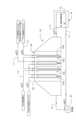
ブロックCに示すように、パワーシステム3の効率をさらに高めるために、蒸気タービン5に高温の過熱蒸気を供給することが必要である(又は非常に好ましい)ことが理解されるであろう。しかし、図2に示すように、蒸気タービンを効率的に稼動させるのに必要な蒸気を過熱するのに十分な温度及び熱容量を有する先行技術の再生可能エネルギーシステムが利用可能であり、供給源(例えば、レシーバ)から貯蔵タンク及び過熱器に向かう高温の作動流体を処理するように設計されている。その結果、システムは、高温の作動流体に耐えるために、さらに高価な高温金属の使用を必要とし、さらに大きなヘリオスタットフィールドなどを必要とした。これらの高温、及び発電に必要とされる規模で使用するための一部の装備(例えば、高温の作動流体ポンプ)は、まだ利用できない可能性があり、開発が必要とされる。このような高温装備のコストは、非常に高く、法外なコストになる可能性がある。It will be appreciated that it is necessary (or highly desirable) to provide hot superheated steam to the
対照的に、本開示の区画化された再生可能エネルギーシステム1の利用と共に、第2再生可能エネルギーシステム11の高温部分20だけが蒸気タービンに供給される蒸気を過熱するのに必要な高温の作動流体を処理するように設計及びエンジニアリングされる必要がある。これは、本開示のシステム1全体の大幅なコストの削減、効率を改善、及び運用及び保持コストを最小限に抑える結果をもたらす。In contrast, with the utilization of the compartmentalized
また、当業者には、現在の再生可能な発電市場では、PV再生エネルギーシステムが発電のために比較的安価な方法を構成することが一般に受け入れられていることも認識されるだろう。また、方法、材料、電気へのエネルギー変換効率などの進歩により、PV発電に関連するコストが継続的に減少する点も一般に認められている。そのため、本明細書に開示されるように、標準的なCSPプラント(例えば、図2など)の最高温度の部分を、PV(又は他の発電)再生可能エネルギーシステムからの熱による高温熱生成に置き換えることが好ましい。さらに、当業者は、溶融金属又は半金属の蓄熱媒体又は作動流体の融解潜熱などの高温蓄熱システムが比較的安価であり、現在利用可能であることを認識するであろう。温タンク29などの高温蓄熱システム内の作動流体を加熱するために、低コストのPV電気を使用することは、CSP再生可能エネルギーシステム9(図2参照)全体で高温の作動流体を生成する必要がなく、発電サイクルに高温熱を提供するための比較的安価な経路を提供する。これは、システムのCSP部分からの熱のコストが大幅に削減される可能性があり、従って、低/中又は第1再生可能エネルギーシステム9で低グレードの作動流体(例えば、溶融塩)を使用でき、構成要素及び配管を、より低温、より低コストの材料で製造できるようにする。Those skilled in the art will also recognize that in the current renewable power generation market, it is generally accepted that PV renewable energy systems constitute a relatively inexpensive way to generate electricity. It is also generally recognized that the costs associated with PV power generation will continue to decrease due to advances in methods, materials, efficiency of energy conversion to electricity, etc. Therefore, as disclosed herein, it is preferable to replace the hottest parts of a standard CSP plant (e.g., FIG. 2, etc.) with high temperature heat generation from heat from a PV (or other power generation) renewable energy system. Furthermore, those skilled in the art will recognize that high temperature heat storage systems, such as molten metal or metalloid heat storage media or latent heat of fusion of working fluids, are relatively inexpensive and currently available. Using low-cost PV electricity to heat the working fluid in a high temperature heat storage system, such as
さらに、本開示によれば、CSPシステムのヘリオスタットフィールドのサイズが減少する可能性があり、これにより、ヘリオスタットシステムのサイズ及びコストが低減される。これは、低温/中温蒸気を生成するための第1又は低温/中温システム9を含む区画化された再生可能エネルギーシステムを使用し、次に蓄熱媒体(例えば、溶融シリコンなど)を高温に加熱して高温蓄熱媒体を温タンク29に貯蔵する光電池(PV)及び/又は他の再生可能なエネルギー発電システムなどの第2再生可能エネルギーシステム11を使用することによって、CSPサイクルの大幅なコスト削減をもたらす。第2再生可能エネルギーシステムが稼動中、及び太陽が照らさない夜間など、第2再生可能エネルギーシステムが動作しない長時間において、第1又はより低温の再生可能エネルギーシステムによって生成される低温/中温蒸気を過熱するのに十分な高温まで伝熱ガスを加熱するだけでなく、タンク29に十分な量の蓄熱媒体があることが理解され得る。Furthermore, according to the present disclosure, the size of the heliostat field of the CSP system may be reduced, thereby reducing the size and cost of the heliostat system. This results in a significant cost reduction of the CSP cycle by using a compartmentalized renewable energy system including a first or low/
当業者には理解されるように、先行技術のCSPシステムは、システム入り、全体にわたって温度を上げることによって、発電サイクルの全体的な効率を上げようとする。前述のように、これは、このような高温を処理するために高温及び高コストの材料を使用する必要があり、従って、より効率的な発電サイクルを加熱するために、高温で十分なレシーバ作動流体の質量の流れを生成するために大きなヘリオスタットフィールドを必要とする。As will be appreciated by those skilled in the art, prior art CSP systems attempt to increase the overall efficiency of the power generation cycle by increasing the temperature into and throughout the system. As previously discussed, this requires the use of high temperature and costly materials to handle such high temperatures, and therefore requires large heliostat fields to generate sufficient receiver working fluid mass flow at high temperatures to heat a more efficient power generation cycle.
発電サイクル:図1は、この場合、太陽熱生成(solar heat generation)の2つの区画又はセグメントであるCSP及びPVを結合し、共通の動力サイクルの個別の部分に熱を共に提供する例示的な蒸気/水力発電サイクルを提示する。図2には、比較/対照のための標準(先行技術)CSP蒸気/水サイクルが示されている。図2では、温タンクを介した太陽光レシーバからの作動流体は、直列配列の蒸気/水力サイクルの蒸気/水過熱セクションを介して処理され、冷タンクに戻り、加熱のために太陽光レシーバに戻される。これには、必要な量の過熱蒸気を供給し、蒸気タービンに過熱蒸気を供給するのに十分な温度及び圧力まで蒸気を加熱するCSPシステムが必要である。これには、CSPレシーバの一部、CSPレシーバを温タンクに接続する配管、及び温タンクから再熱器/過熱器までの配管を高温材料で設計及び構成する必要がある。レシーバから温タンクまで、及び温タンクから再熱器/過熱器まではある程度の距離がある場合があるため、システムのかなりの部分を、Inconel(登録商標)合金などのような高温材料で構成する必要がある。Power generation cycle: FIG. 1 presents an exemplary steam/hydro power cycle that combines two sections or segments of solar heat generation, in this case CSP and PV, together providing heat to separate parts of a common power cycle. In FIG. 2, a standard (prior art) CSP steam/water cycle is shown for comparison/control. In FIG. 2, the working fluid from the solar receiver via the hot tank is processed through the steam/water superheat section of the steam/hydro cycle in series arrangement, back to the cold tank, and back to the solar receiver for heating. This requires the CSP system to provide the required amount of superheated steam and heat the steam to a temperature and pressure sufficient to supply the superheated steam to the steam turbine. This requires parts of the CSP receiver, the piping connecting the CSP receiver to the hot tank, and the piping from the hot tank to the reheater/superheater to be designed and constructed of high temperature materials. Because there may be some distance between the receiver and the hot tank, and from the hot tank to the reheater/superheater, a significant portion of the system must be constructed from high temperature materials such as Inconel® alloys.
発電サイクル(power generating cycle)は、亜臨界(sub-critical)、トランス臨界(trans-critical)、及び/又は超臨界(cuper-critical)CO2パワーサイクル、ORC、又は第2パワーサイクル作動流体が、熱及び/又は電力の生成に有用な方法で、従来の太陽光レシーバ作動流体から熱を受ける多くの選択肢の1つであり得る。 The power generating cycle can be one of many options in which a sub-critical, trans-critical, and/or super-criticalCO2 power cycle, ORC, or second power cycle working fluid receives heat from a conventional solar receiver working fluid in a manner useful for generating heat and/or power.
上述のメインパワーシステム3及び2つの区画化された再生可能エネルギーシステム9,11を有する上記の区画化されたシステム1が好ましい場合があるが、「電力タワー」CSPは「トラフ型」CSPシステムに置換え得ることがわかるであろう。さらに、第2再生可能エネルギーシステム11と関して説明したPVシステムは、風力、水力、又は地熱発電システムに置換えることができ、風力システムによって生成された電気の一部は、例えば、図1に示すPVシステムの代わりに、タンク29内の高温の溶融金属作動流体を加熱するために使用される。風を使用するこのようなシステムでは、温タンク29は、十分な量の高温の蓄熱媒体(例えば、溶融金属又は溶融半金属)を貯蔵して、十分な風が利用できない期間に再熱器/過熱器19の高温の過熱蒸気を生成するために使用できるようにする。もちろん、適切な電池蓄電システムがタンク29及び溶融蓄熱媒体の代わりに使用されてもよく、又はそのような蓄電池システムが、追加の蓄熱又はバックアップの目的に使用されてもよい。もちろん、第2再生可能システム11が水力又は地熱発電システムである場合、蓄熱媒体のサイズ又はさらに必要性さえも減少又は排除することができ、伝熱ガスは、電気加熱器によって直接加熱することができる。PV、風力、及び電池バックアップの様々な組み合わせが使用され得る。また、水力発電、地熱、燃料電池、揚水貯蔵(pumped storage)、及び異なる形態の蓄熱など、異なる形態の再生可能エネルギーシステムが使用され得る。While the above-mentioned
さらに、当業者は、図1に示される単一の再熱蒸気/水電気発電システム3は、例えば、複数の再熱亜臨界蒸気/水力サイクル、複数の再熱超臨界蒸気/水力サイクル、又は複数の再熱超亜臨界蒸気/水力サイクルで、及び/又は次のもので置換えることができることを理解するであろう。
a.説明された高圧(HP)及び再加熱(RH)蒸気システムに加えて、中圧(IP)及び/又は低圧(LP)蒸気システムが追加され得る。
b.電力に加えて有用な熱を送りだすように、工程用の他のシステム加熱器を追加する。
c.例えば、復熱(recuperation)、中間冷却(intercooling)、過給(supercharging)、その他の全てのサイクル構成を有する及び/又は有しない亜臨界、超臨界、混合圧力CO2サイクル。
d.例えば、復熱、中間冷却、過給、その他の全てのサイクル構成、組み合わせ、及び上記の順列を有する及び/又は有しないORCサイクル。 Further, those skilled in the art will appreciate that the single reheat steam/water electric
In addition to the high pressure (HP) and reheat (RH) steam systems described, intermediate pressure (IP) and/or low pressure (LP) steam systems may be added.
b. Add other system heaters to the process to deliver useful heat in addition to power.
c. For example, subcritical, supercritical, mixed pressure CO2cycles with and/or without recuperation, intercooling, supercharging and all other cycle configurations.
d. ORC cycles, for example, with and/or without recuperator, intercooler, supercharger, and all other cycle configurations, combinations, and permutations of the above.
図2に示すように、従来のCSP電力及び/又は熱生成及び貯蔵施設は、一般にヘリオスタットフィールドが受信機の吸収エネルギーで加熱されるCSP作動流体を含む受信機に太陽輻射線を集中させる形態である。現在のプラントでは、蒸気/水のパワーサイクル作動流体を利用して、温タンクからの作動流体から熱を吸収し、その流体を冷タンクに戻してレシーバ内のCSP作動流体を再加熱する。パワーサイクルの効率を上げるために、パワーサイクル作動流体の圧力及び温度は、利用可能な装備の設計能力の範囲内で最大化される。パワーサイクル作動流体の温度を最大化するために、CSP作動流体も非常に高温にする必要があり、実際には、パワーサイクル作動流体に必要な温度よりも高温になる。As shown in FIG. 2, conventional CSP power and/or heat generation and storage facilities are typically configured with a heliostat field concentrating solar radiation onto a receiver containing a CSP working fluid that is heated by the absorbed energy of the receiver. Current plants utilize a steam/water power cycle working fluid to absorb heat from the working fluid from a hot tank and return the fluid to a cold tank to reheat the CSP working fluid in the receiver. To increase the efficiency of the power cycle, the pressure and temperature of the power cycle working fluid are maximized within the design capabilities of the available equipment. To maximize the temperature of the power cycle working fluid, the CSP working fluid must also be very hot, in fact hotter than required for the power cycle working fluid.
特に、太陽と雲が交互に発生する相対的に大きい(少なくとも従来の化学燃料プラントに比べて)負荷変化は、短時間内でライフサイクルの利用率が大幅に強化される可能性がある。これは、特に溶融塩で蒸気/水への熱交換器のCSPアプリケーションで現在一般的に使用されている厚いチューブ/シートシェルアンドチューブ熱交換器(HXs)で、急速な疲労破壊につながる可能性がある。In particular, the relatively large (at least compared to conventional chemical-fuel plants) load changes caused by alternating sun and clouds can significantly enhance life cycle utilization within a short period of time. This can lead to rapid fatigue failure in thick tube/sheet shell-and-tube heat exchangers (HXs) currently commonly used in CSP applications, especially in molten salt to steam/water heat exchangers.
雲が太陽の位置とヘリオスタットフィールドの位置との間を通過するとき、実質的に「瞬時」に消え得る太陽熱の利用可能性の特性は複合的である。これにより、CSP作動流体及びパワーサイクル作動流体の両方の質量の流れ及び温度が急速に変化する。現在、熱は一般にシェルアンドチューブ熱交換器を使用して2つの作動流体の間で伝達されるため、これらの稼動温度差勾配のライフサイクルへの影響を考慮する必要がある。通常、パワーサイクル作動流体の稼動圧力と温度が高いため、これらのシェルアンドチューブ熱交換器は、非常に特殊な設計にする必要があり、及び/又は低サイクルの疲労損傷に悩まされる。CSPレシーバの現在の状態は、シェルアンドチューブ熱交換器が正常に許容できるピーク温度にほぼ到達した状態である。同様に、CSP作動流体及びパワーサイクル作動流体の温度では、パワーサイクル作動流体(PCWF)の圧力も基本的に現在のCSPプラントのスタイルの最大値に到達している。最悪の問題は、温度が最も高く、パワーサイクル作動流体の圧力が非常に高いままのHPSHTRバンドルにある。特に温タンクでの貯蔵には問題がある。塩温度の上昇、及びこれらのより高い温度を保持できる塩の使用は、材料及び溶融塩のコストを上昇させる可能性があり、さらにシェルアンドチューブ熱交換器の問題を複雑にする。The solar heat availability characteristic is compounded as it can disappear virtually "instantaneously" when a cloud passes between the sun's position and the heliostat field's position. This causes rapid changes in mass flow and temperature of both the CSP working fluid and the power cycle working fluid. Currently, heat is generally transferred between the two working fluids using shell-and-tube heat exchangers, so the life cycle impact of these operating temperature difference gradients must be considered. Typically, due to the high operating pressure and temperature of the power cycle working fluid, these shell-and-tube heat exchangers must be very specially designed and/or suffer from low cycle fatigue damage. The current state of the CSP receiver is one where the shell-and-tube heat exchanger has almost reached the peak temperature that can be normally tolerated. Similarly, at the temperatures of the CSP working fluid and the power cycle working fluid, the pressure of the power cycle working fluid (PCWF) has also essentially reached the maximum for the current style of CSP plant. The worst problem is in the HPSHTR bundle, where the temperature is the highest and the pressure of the power cycle working fluid remains very high. Storage in hot tanks is especially problematic. Increasing salt temperatures, and the use of salts that can sustain these higher temperatures, can increase the cost of materials and molten salts, further complicating the problem for shell-and-tube heat exchangers.
現在の技術は、パワーサイクルの効率性のためにCSP溶融塩出口/高温に依存している。この高温の溶融塩の温度を高めることは、2つの主な要因により非常にコストがかかる。1.レシーバ材料及び溶融塩種を、より高温で稼動できる材料及び塩に昇格する必要がある。2.ヘリオスタットフィールドへの重要な活性領域の追加。上記の両方の要因により、CSP発電施設全体にかなりのコストがかかる。追加のコストの増加は、配管、溶融塩タンク、ポンプ、及びその他の周辺機器の高合金材料への増加に関連するものである。発電ランキンサイクルのための蒸気を高めるために使用される現在の溶融塩から蒸気/水へのシェルアンドチューブ熱交換器の配置には、重大な技術的課題が存在する。他のタイプの熱伝達も使用できるが、コストが大幅に増加する。Current technology relies on the CSP molten salt outlet/high temperature for power cycle efficiency. Increasing the temperature of this high temperature molten salt is very costly due to two main factors: 1. The receiver material and molten salt species need to be upgraded to materials and salts that can operate at higher temperatures; and 2. The addition of significant active area to the heliostat field. Both of the above factors add significant cost to the overall CSP power plant. The additional cost increase is associated with the increase to higher alloy materials for the piping, molten salt tanks, pumps, and other peripheral equipment. Significant technical challenges exist with the current molten salt to steam/water shell-and-tube heat exchanger arrangements used to boost steam for the power generation Rankine cycle. Other types of heat transfer can be used but at significantly increased costs.
安価な高温溶融塩又は半金属潜熱エネルギー貯蔵と組合せて安価なPVを利用すると、塩の温度をさらに上昇させる必要がなくなり、付随する全ての問題が回避される。Utilizing cheap PV in combination with cheap high temperature molten salt or metalloid latent heat energy storage would eliminate the need to further increase the temperature of the salt, avoiding all the associated problems.
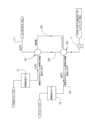
ここで図3Aを参照すると、概略的に101で示される熱回収蒸気生成型(HRSG-like)アセンブリが、図1に示すように再熱器/過熱器19の代替又は拡張実施形態として示されている。より具体的には、アセンブリ101は、図1及び図3に示すように、例えば、HRSG型装置の密閉ハウジング105内に配置された103a,103b,103c、及び103dで示される1つ以上のコイルを加熱するために、第2再生可能エネルギーシステム11から熱を供給される。本説明によれば、同じ目的又は異なる目的のために、より少ない又はより多いコイルをハウジング105に設けることができることを理解されたい。図3Aに示すように、窒素ガスなどの作動流体は、上述のように、電気加熱器28を介して第2再生可能エネルギーシステム11によって加熱される高温貯蔵タンク29内の高温蓄熱材料30(例えば、溶融金属又は半金属)によって加熱される。作動流体は、ライン31を介して十分に高い温度及び十分に高い質量流量でタンク29を出て、後述する目的のために、コイル103a,103b,103c,103d、及び内部の流体を加熱する。もちろん、作動流体がハウジング105を介して流れると、作動流体内の熱エネルギーがコイルに伝達され、作動流体が各コイルを流れる際に冷却される。作動流体は、ハウジング105を出て、高温送風機107は、作動流体をタンク29内の蓄熱媒体30によって再加熱するように、ライン33を介してタンク29に戻される。図に示すように、タンク29を出る作動流体の温度は、例えば、約1100℃であり、送風機107を出る作動流体の温度は、約500℃であり得るが、これらの温度は単なる例示であり、状況に応じてかなり変化し得る。3A, a heat recovery steam generator (HRSG-like) assembly, generally designated 101, is shown as an alternative or extended embodiment of the reheater/
図3Aにさらに示されるように、コイル103dは、約370℃の温度でライン109を介してタービン5の高圧段から蒸気を受け取り、コイル103dを通過して熱回収蒸気発生器型(HRSG)アセンブリ101を介して流れる作動流体によって再加熱される。コイル103dによって再加熱された蒸気は、コイル103dの上流のコイル103bの入口に供給され、そこで約630℃まで過熱され、その後、ライン111を介して蒸気タービン5の中圧段に供給される。あるいは、コイル103bを出る蒸気は、蒸気タービン5の高圧段に供給されてもよい。さらに、蒸発器15からの蒸気は、ライン113を介して、第1高圧過熱器として機能するコイル103cの入口に供給される。コイル103cを出る過熱蒸気は、コイル103aの入口に供給され、コイル103aに合う際に流入する高温の作動流体(最高温度にある)によってさらに過熱される。コイル103aの出口からの過熱蒸気は、ライン113によってタービン5の高圧段に送られる。As further shown in FIG. 3A, the
図4,図4A、及び図4Bを参照すると、図1~図3のエコノマイザ/蒸発器15が蒸発器201及びエコノマイザ203を含むように、より詳細に示されている。温タンク23からの溶融塩は、約470℃で蒸発器201に入り、蒸発器から排出され、より低温でライン205によってエコノマイザ203に伝達されるが、依然としてポンプ17によってエコノマイザ203に供給される給水及び凝縮液の温度よりも十分に高い。ポンプ17によって凝縮器13からエコノマイザ203に供給される給水及び/又は凝縮液は、ライン205を介してエコノマイザ203に流れる蒸発器201から出る溶融塩よりも低い温度である。図4Aに示すように、給水及び/又は凝縮液は、エコノマイザ203内の溶融塩によって加熱される。溶融塩は、ライン207を介して約290℃の温度で冷タンク205に戻される。エコノマイザ203で加熱された給水は、ライン209を介して蒸発器201に供給される。図3Aに示すように、蒸発器201からの蒸気は、ライン211を介して約460℃の温度で高圧過熱器103aに供給される。蒸発器201及びエコノマイザ203は、図4Bに示すように、複数の平行なシェル及び管熱交換器を含み得ることが理解されるであろう。4, 4A, and 4B, the economizer/
図4Bでは、一般に203a,203bで示される一対のエコノマイザ/蒸発器が示されている。それぞれは、蒸発器217a,217b及びエコノマイザ219a,219bを含む。それぞれのエコノマイザ217a,217bは、それぞれのライン221a,221bを介してポンプ17(図1に示すように)を介して凝縮器13から高圧ボイラ給水及び/又は凝縮液を受け取り、給水がそれぞれのエコノマイザ219a,219bで加熱されるようにする。加熱された水は、それぞれのライン223a,223bによってそれぞれの蒸発器217a,217bの入口に供給される。溶融塩は、蒸発器217a,217bからそれぞれのライン225a,225bを介して排出され、凝縮器13から受け取った給水を最初に加熱するために、エコノマイザ219a,219bの入口に供給される。依然として、溶融塩は約290℃の温度でライン227を介してエコノマイザ219a,219bから冷タンク25に戻される。蒸発器217a,217bからの蒸気は、ライン229を介して図3Aの高圧過熱器コイル103aに供給される。In FIG. 4B, a pair of economizer/evaporators are shown, generally designated 203a, 203b. Each includes an
ここで図5及び図5Aを参照すると、図1のエコノマイザ/蒸発器15及び再熱器/過熱器19は、それぞれ概略的に301,303で示されるように、2つの個別のHRSG型アセンブリの一部として示されている。先ず、HRSG型アセンブリ301を参照すると、温タンク23からの高温の溶融塩が、入口端309及び出口端311を有するハウジング307に配置される第1コイル305a及び最後又は第4のコイル305dに供給される。コイル305a,305dは、再循環ダクト又は通路313によって出口311から入口309に再循環される約470℃より幾分低い温度まで空気(又は別の適切な作動流体)を加熱するための溶融塩加熱器として機能する。もちろん、適切な高温ファン又は送風機(図示せず)が、加熱された空気を入口から出口まで、及び再循環ダクトを介してハウジング307を通って移動するように、再循環ダクトに組み込まれる。給水/凝縮液ポンプ17からの凝縮液及び/又は給水は、給水/凝縮液を加熱し、加熱された給水/凝縮液を第2コイル305bの入口317に供給するエコノマイザとして機能する第3コイル305cの入口315に供給される。この最後に述べたコイルは、分離器319に供給される約460℃より幾分低い温度で蒸気を生成するための蒸発器としての機能をする。HRSGアセンブリ301の熱は全て、第1再生可能エネルギーシステム9によって供給されることに留意されたい。5 and 5A, the economizer/
HRSG型アセンブリ303は、323a,323b,323c,323dで示される複数のコイルを収容するハウジング321を含む。ハウジング321は、入口端325及び出口端327を有する。窒素などの作動流体は、タンク29に貯蔵された高温の作動流体によって高温(例えば、約1100℃)に加熱され、ハウジング321の入口端325に供給される。この高温の作動流体は、ハウジングを介して最初にコイル323aを通る又は過ぎるように連続的に流れた後、順次他のコイル323b,323c,323dを通る又は過ぎる。作動流体は、より低温(例えば、約500℃)で出口327を介してハウジングを出て、タンク29の高温蓄熱媒体30によって再加熱されるように、再循環ダクト又は通路329によってタンク29に再び再循環される。もちろん、高温送風機又はファン330は、作動流体を再循環させるために、再循環ダクトに組み込まれる。
蒸気タービン5の高圧段からの蒸気は、再熱器として機能する第4コイル323dの入口端に供給される。再加熱コイル323dを出ると、再加熱された蒸気は、第2再熱器として機能する第2コイル323bの入口に流れる。第2再熱器コイル323bを出る蒸気は、タービン5の中間段に、又は代替的に高圧蒸気タービンの段に供給される。分離器319からの蒸気は、第1高圧過熱器として機能する第3コイル323cの入口に供給される。過熱蒸気は、コイル323cを出て、第2高圧過熱器として機能する第1コイル323aの入口に供給される。過熱された高圧蒸気は、約630℃の温度でコイル323aを出て、タービン5の高圧段に供給される。もちろん、高温の作動流体が入口325から出口327に流れ、コイル323a~323dの上を超える又通過するとき、作動流体の温度は低下する。Steam from the high pressure stage of the
ここで図6、図6Aを参照すると、図1のエコノマイザ/蒸発器15及び再熱器/過熱器19を構成する本開示のシステムと幾分異なる実施形態が示されている。図5Aに示される実施形態と同様に、図6Aは、図1のエコノマイザ/蒸発器15及び再熱器/過熱器19は、それぞれ概略的に401及び403で示されるように、エコノマイザ/蒸発器15の均等物を構成するアセンブリ401と、再熱器/過熱器19の均等物を構成するアセンブリ403とを有する2つの個別のHRSG型アセンブリの部分からなる。Referring now to Figures 6 and 6A, a somewhat different embodiment of the disclosed system is shown that constitutes the economizer/
アセンブリ403は、入口407及び出口409を有するハウジング405と、ハウジング405内に配置される411a,411b,411c、及び411dで示された複数のコイルとを有するように図6Aに示されている。入口407は、タンク29に貯蔵された高温蓄熱媒体30によって高温(例えば、約1100℃)に加熱された窒素などの高温の作動流体を受け取る。高温の作動流体が入口407から出口409までハウジング405を介して流れるとき、ハウジング内のコイルは、後述する目的のためにハウジング405を介して流れる作動流体によって連続的に加熱される。従って、アセンブリ403に配置されるコイルは、第2再生可能エネルギーシステム11によって加熱される。
アセンブリ401は、入口端413及び出口端415を有するハウジング411を有する。417a,417b,417c及び417dで示されるように、複数のコイルがハウジング411内に取り付けられる。出口409を介してハウジング405から排出される作動流体は、ハウジング411の入口413に入るときに約500℃の温度を有する。作動流体がハウジング411を通って流れると、作動流体は、コイル417a~417dを連続的に加熱する。出口415から排出された作動流体は、再循環システム416に入る。より具体的には、再循環システムは、作動流体を、高温蓄熱媒体30によって再加熱されるタンク29に再び再循環させる高温ファン421を有する。
図6Aにさらに示すように、例えば、約565℃の温度の温タンク23からの溶融塩が、第1及び第4コイル417a,417dの入口に導入され、これらの最後のコイルが、ハウジング411を介して流れるHRSG型アセンブリ403から流れる作動流体を加熱(より正確に再加熱)するようにする。アセンブリ403内の作動流体のこの再加熱は、第1再生可能エネルギーシステム9によって実行される。凝縮器13からの給水/凝縮液は、ポンプ17によって、エコノマイザとして機能する第3コイル417cの入口に導入され、ハウジング411を介して流れる作動流体によって加熱される。第3コイル417cを出る加熱された給水は、第1コイル417bの入口に導入され、そこでハウジング411を介して流れる作動流体によって蒸発され、中圧蒸気を形成する。蒸発器コイル417bで蒸発した蒸気は、蒸気を任意の液体水から分離する分離器419に流れ、液体水が凝縮器13に戻され、蒸気がアセンブリ403のコイル411cの入口に供給され、そこで蒸気が過熱されてコイル411cが第1高圧過熱器として機能するようにする。コイル411cの出口からの過熱蒸気は、第2の高圧過熱器コイル411aに供給され、続いて蒸気タービン5の高圧段に供給される。6A, molten salt from the
さらに、図6Aに示すように、タービン5の高圧段からの蒸気がコイル411dの入口に供給され、そこでハウジング405を介して流れる作動流体によって再加熱される。再加熱された蒸気は、コイル411dを出て、コイル411bの入口に供給され、コイル411bが第2再熱器として機能するように再加熱される。コイル411bの出口からの再加熱された蒸気は、タービン5の中間段に供給される。Furthermore, as shown in FIG. 6A, steam from the high pressure stage of
ここで図7を参照すると、図1に関して説明した再熱器/過熱器19のより詳細な図が示されている。図7では、再熱器/過熱器19は、2つのセクション、即ち、高圧過熱器501及び再熱器503を含むように示されている。過熱器501は、ライン505を介して約460℃の温度で蒸発器15から中圧蒸気を受け取る。図1に示すように、再熱器/過熱器19は、ライン31を介して高温タンク29から高温の作動流体、好ましくは窒素を受け取り、ライン31は図7にも示されている。前述したように、タンク29から供給される作動流体は高温であり、例えば約1100℃である。図7に示すように、流入する中圧蒸気は、過熱器501で高温の作動流体によって過熱され、例えば、約630℃の高温の過熱蒸気は、ライン507を経由して蒸気タービン5の高圧段に供給される。7, there is shown a more detailed view of the reheater/
高温の作動流体が過熱器501及び再熱器503を介して又はその周辺に流れるとき、その温度は、高温の作動流体が先ず過熱器の周辺に流れ、次に再熱器の周辺に流れるにつれて低下することが理解されよう。再熱器503は、例えば、約460℃の温度でライン509を介してタービン5の高圧段から排気を受け取る。この蒸気は、約630℃に再加熱され、ライン511を介してタービン5の中圧段に供給される。作動流体が再熱器509から排出されると、ライン33を介して温タンク29に再循環される。It will be appreciated that as the hot working fluid flows through or around the
本開示の広い範囲から逸脱することなく、上述した構築方法に様々な変更を加えることができ、上記の説明に含まれる又は添付の図面に示される全ての事項は、例示として解釈されるべきであり、限定的な意味で解釈されるべきではないことを意図する。Various changes may be made in the construction methods described above without departing from the broad scope of the present disclosure, and it is intended that all matter contained in the above description or shown in the accompanying drawings be interpreted as illustrative and not in a limiting sense.
Claims (47)
Translated fromJapanese発電機を駆動するように構成された蒸気タービンを有する蒸気動力発電システムと、
低温/中温蒸気を生成するように構成された第1又は低温/中温再生可能エネルギーシステムと、
前記第1又は低温/中温再生可能エネルギーシステムによって生成された低温/中温蒸気を過熱し、過熱蒸気を前記蒸気タービンに供給して前記蒸気タービンが効率的に作動するように構成された第2又は高温再生可能エネルギーシステムと、
を含み、
前記第1又は低温/中温再生可能エネルギーシステムは、太陽エネルギーを使用して第1作動流体を低温/中温に加熱し、前記第1又は低温/中温再生可能エネルギーシステムが太陽エネルギーを受けるとき、及び長時間にわたり太陽から直接エネルギーを利用できないときの両方において、前記低温/中温蒸気を生成するのに十分な前記低温/中温に加熱された十分な量の前記第1作動流体を貯蔵するように構成され、
前記第2又は高温再生可能エネルギーシステムは、高温蓄熱媒体を高い温度に加熱するように第2再生可能エネルギー源を使用して過熱蒸気が前記蒸気タービンに供給されるように前記第1又は低温/中温再生可能エネルギーシステムによって生成された前記低温/中温蒸気を過熱するために、高温熱伝達作動媒体を十分に高い温度に加熱するように、前記高温蓄熱媒体を利用するように構成される、
再生可能な発電システム。 1. A renewable power generation system, comprising:
a steam powered power generation system having a steam turbine configured to drive a generator;
a first or low/medium temperature renewable energy system configured to generate low/medium temperature steam;
a second or high temperature renewable energy system configured to superheat low/medium temperature steam produced by thefirst or low/medium temperature renewable energy system and supply the superheated steam to the steam turbine such that the steam turbine operates efficiently;
Including,
the first or low/medium temperature renewable energy system is configured to use solar energy to heat a first working fluid to a low/medium temperature and to store a sufficient amount of the first working fluid heated to the low/medium temperature sufficient to generate the low/medium temperature steam both when the firstor low/medium temperature renewable energy system receives solar energy and when energy is not available directly from the sun for extended periods of time;
the second or high temperature renewable energy system is configured to utilize the high temperature heat storage medium to heat a high temperature heat transfer working medium to a sufficiently high temperature to superheat the low/medium temperature steam produced bythe first or low/medium temperature renewable energy system using a second renewable energy source to heat the high temperature heat storage medium to a high temperature such that the superheated steam is supplied to the steam turbine;
Renewable power generation systems.
発電機を駆動するように構成された蒸気タービンを有する蒸気動力発電システムと、
低温/中温蒸気を生成するように構成された第1又は低温/中温再生可能エネルギーシステムと、
前記第1又は低温/中温再生可能エネルギーシステムによって生成された低温/中温蒸気を過熱し、過熱蒸気を前記蒸気タービンに供給して前記蒸気タービンが効率的に作動するように構成された第2又は高温再生可能エネルギーシステムと、
を含み、
前記第1又は低温/中温再生可能エネルギーシステムは、太陽エネルギーを使用して第1作動流体を低温/中温に加熱し、前記第1又は低温/中温再生可能エネルギーシステムが太陽エネルギーを受けるとき、及び長時間にわたり太陽から直接エネルギーを使用できないときの両方において、前記低温/中温蒸気を生成するのに十分な前記低温/中温に加熱された十分な量の前記第1作動流体を貯蔵するように構成され、
前記第2又は高温再生可能エネルギーシステムは、高温蓄熱媒体を高い温度に加熱できるように第2再生可能エネルギー源を使用して、ガスの高温熱伝達作動媒体を十分に高い温度に加熱するように、前記高温蓄熱媒体を使用して、前記過熱されたガスが前記第1又は低温/中温再生可能エネルギーシステムによって生成された前記低温/中温蒸気を過熱できるように構成され、過熱蒸気が前記蒸気タービンに供給されるようにし、
前記第2又は高温再生可能エネルギーシステムは、電気を生成するように構成され、前記第2又は高温再生可能エネルギーシステムによって生成された電気の少なくとも一部は、前記熱伝達ガスが前記蓄熱媒体と熱伝達関係にあるときに、前記伝熱ガスを加熱するのに十分な高温まで前記高温蓄熱媒体を電気的に加熱するように構成され、
前記伝熱ガスが、前記低温/中温蒸気と、前記高温に加熱された前記蓄熱媒体の供給を保持するためのタンクと、前記第1又は低温/中温再生可能エネルギーシステムによって生成された前記低温/中温蒸気を過熱するための前記伝熱ガスによって加熱されて前記蒸気タービンに過熱蒸気を供給するように構成された過熱器と、を過熱できる、
再生可能な発電システム。 1. A renewable power generation system, comprising:
a steam powered power generation system having a steam turbine configured to drive a generator;
a first or low/medium temperature renewable energy system configured to generate low/medium temperature steam;
a second or high temperature renewable energy system configured to superheat low/medium temperature steam produced by thefirst or low/medium temperature renewable energy system and supply the superheated steam to the steam turbine such that the steam turbine operates efficiently;
Including,
the first or low/medium temperature renewable energy system is configured to use solar energy to heat a first working fluid to a low/medium temperature and to store a sufficient amount of the first working fluid heated to the low/medium temperature sufficient to generate the low/medium temperature steam both when the firstor low/medium temperature renewable energy system receives solar energy and when energy is not available directly from the sun for extended periods of time;
the second or high temperature renewable energy system is configured to use a second renewable energy source to heat a gaseous high temperature heat transfer working medium to a sufficiently high temperature such that a high temperature heat storage medium can be heated to a high temperature, the high temperature heat storage medium can be used to allow the superheated gas to superheat the low temperature/medium temperature steam generated bythe first or low temperature/medium temperature renewable energy system , and the superheated steam can be supplied to the steam turbine;
the second or high temperature renewable energy system is configured to generate electricity, and at least a portion of the electricity generated bythe second or high temperature renewable energy system is configured to electrically heat the high temperature heat storage medium to a high temperature sufficient to heat the heat transfer gas when the heat transfer gas is in heat transfer relationship with the heat storage medium;
the heat transfer gas can superheat the low/medium temperature steam, a tank for holding a supply of the heat storage medium heated to the high temperature, and a superheater configured to be heated by the heat transfer gas for superheating the low/medium temperature steam generated bythe first or low/medium temperature renewable energy system to supply superheated steam to the steam turbine;
Renewable power generation systems.
前記システムは、過熱蒸気を前記蒸気タービンに供給するために、前記低温/中温蒸気を過熱するのに十分な温度及び流量で前記過熱器に前記加熱した伝熱ガスを供給するように構成される、請求項6に記載の再生可能な発電システム。 the system is configured to circulate the heat storage gas at low pressure in heat transfer relationship with the molten heat storage medium;
7. The renewable power generation system of claim 6, wherein the system is configured to supply the heated heat transfer gas to the superheater at a temperature and flow rate sufficient to superheat the low/medium temperature steam to supply superheated steam to the steam turbine.
前記凝縮器からの凝縮液は、前記低温/中温蒸気を生成するために蒸発器に供給される、請求項1に記載の再生可能な発電システム。 the system is configured such that after the superheated steam drives the steam turbine, low temperature steam and/or condensate flows from the steam turbine to a condenser;
The renewable power generation system of claim 1 , wherein condensate from the condenser is fed to an evaporator to generate the low/medium temperature steam.
前記第1作動流体は、溶融塩作動流体である、請求項1に記載の再生可能な発電システム。the first or low/medium temperature renewable energy system is selected from the group consisting of a concentrating solar power system and a trough reflector system;
The renewable power generation system of claim 1 , wherein the first working fluid is a molten salt working fluid.
前記溶融蓄熱媒体、
供給される低温/中温蒸気を過熱するように構成された過熱器、及び
前記溶融蓄熱媒体によって前記伝熱ガスが過熱された後に、前記低温/中温蒸気を過熱するように前記過熱器に前記伝熱ガスを供給するように構成された配管の過度の酸化又は他の劣化を防止し、
前記高温蓄熱タンク及び前記配管は、前記第2又は高温再生可能エネルギーシステムの高温部分を構成し、
前記高温部分のみが特殊な高温材料で構成される必要がある、
請求項6に記載の再生可能な発電システム。the second or high temperature renewable energy system is configured to have a high temperature portion including the high temperature thermal storage medium storage tank configured to contain a molten thermal storage medium;
The molten heat storage medium,
Preventing excessive oxidation or other deterioration of a superheater configured to superheat the supplied low/medium temperature steam, and a piping configured to supply the heat transfer gas to the superheater to superheat the low/medium temperature steam after the heat transfer gas is superheated by the molten heat storage medium;
The high-temperature heat storage tank and the piping constitute a high-temperature portion ofthe second or high-temperature renewable energy system ;
Only the high temperature parts need to be made of special high temperature materials;
The renewable power generation system of claim 6.
前記溶融蓄熱媒体が、前記伝熱ガスを長時間にわたり前記低温/中温蒸気を過熱するのに十分な温度で加熱できるようにする、請求項13に記載の再生可能な発電システム。 the molten heat storage medium is in a sufficient quantity and at a sufficient temperature;
14. The renewable power generation system of claim 13, wherein the molten heat storage medium enables the heat transfer gas to be heated to a temperature sufficient to superheat the low/medium temperature steam for an extended period of time.
前記第1又は低温/中温再生可能エネルギーシステムは、低温/中温蒸気を生成するように前記低温/中温の作動流体を前記高温貯蔵タンクから前記エコノマイザ/蒸発器に供給するように構成される、請求項3に記載の再生可能な発電システム。the first or low temperature/medium temperature renewable energy system includes an economizer/evaporator;
4. The renewable power generation system of claim 3, whereinthe first or low/medium temperature renewable energy system is configured to supply the low/medium temperature working fluid from the high temperature storage tank to the economizer/evaporator to generate low/medium temperature steam.
前記高圧過熱器は、高温蓄熱タンク29内の前記蓄熱材料30によって高温に加熱された前記伝熱ガスによって加熱するように構成され、前記蒸発器から低温/中温蒸気を供給されることによって、前記蒸気タービンの高圧段に伝達される過熱蒸気を生成するように構成され、
前記再熱器は、前記蒸気タービンからの高圧蒸気タービン排気を受けるように構成され、さらに、前記再加熱する過熱器の前記伝熱ガスによって加熱することによって、前記蒸気タービンの中圧段に伝達される中圧蒸気を生成するように構成される、請求項3に記載の再生可能な発電システム。 The superheater includes a high pressure superheater and a reheater,
the high-pressure superheater is configured to be heated by the heat transfer gas heated to a high temperature by the heat storage material 30 in the high-temperature heat storage tank 29, and is configured to generate superheated steam to be transferred to a high-pressure stage of the steam turbine by receiving low-temperature/medium-temperature steam from the evaporator;
4. The renewable power generation system of claim 3, wherein the reheater is configured to receive high-pressure steam turbine exhaust from the steam turbine and is further configured to generate intermediate-pressure steam by heating with the heat transfer gas of the reheating superheater, for delivery to an intermediate-pressure stage of the steam turbine.
前記エコノマイザは、前記第1作動流体を使用して、前記過熱器に伝達される前記低温/中温蒸気を生成するように構成される、請求項3に記載の再生可能な発電システム。 the evaporator (15, 201) includes an economizer (203) configured to receive condensate from the turbine, the evaporator (15, 201) configured to transfer the first working fluid from the evaporator to the economizer (203), the economizer configured to heat the condensate and transfer the heated condensate to the evaporator;
The renewable power generation system of claim 3 , wherein the economizer is configured to use the first working fluid to generate the low/medium temperature steam that is delivered to the superheater.
前記再生可能エネルギーシステムは、蒸発器及びエコノマイザの第2の対をさらに含み、前記対は互いに並列に接続され、前記温タンク23から前記第1作動流体を受け取るように構成され、
各対の蒸発器及び前記タービンから凝縮液を受け取るように構成された各対のエコノマイザは、
前記各対の前記蒸発器の各々は、前記第1作動流体が前記蒸発器を通過した後、前記第1作動流体を各々のエコノマイザに供給するように構成され、
前記エコノマイザの各々は、前記エコノマイザの各々を介して流れる前記第1作動流体によって前記凝縮液を加熱し、前記加熱された凝縮液を各々の前記蒸発器に伝達するように構成され、
前記エコノマイザの各々は、前記エコノマイザから排出される前記作動流体を冷温貯蔵タンクに伝達するように構成される、請求項21に記載の再生可能な発電システム。 the evaporator and the economizer are configured to form a first evaporator-economiser pair;
the renewable energy system further includes a second pair of evaporators and economizers, the pair connected in parallel with each other and configured to receive the first working fluid from the hot tank 23;
a respective pair of economizers configured to receive condensate from each pair of evaporators and the turbine,
each of the evaporators of each of the pairs is configured to supply the first working fluid to a respective economizer after the first working fluid passes through the evaporator;
each of the economizers is configured to heat the condensate with the first working fluid flowing through each of the economizers and transfer the heated condensate to a respective one of the evaporators;
22. The renewable power generation system of claim 21, wherein each of the economizers is configured to communicate the working fluid discharged from the economizer to a cold storage tank.
発電機を駆動するように構成された蒸気タービンを有する蒸気動力発電システムと、低温/中温蒸気を生成するように構成された第1又は低温/中温再生可能エネルギーシステムと、第1又は低温/中温再生可能エネルギーシステムによって生成された低温/中温蒸気を過熱して過熱蒸気を前記蒸気タービンに供給するように構成された第2又は高温再生可能エネルギーシステムと、を含み、
前記第1又は低温/中温再生可能エネルギーシステムは、太陽エネルギーを使用して第1作動流体を低温/中温に加熱し、前記第1又は低温/中温再生可能エネルギーシステムが太陽エネルギーを受けるとき、及び長時間にわたり太陽からエネルギーを利用できないときの両方において、前記低温/中温蒸気を生成するのに十分な前記低温/中温に加熱された十分な量の前記第1作動流体を貯蔵するように構成され、
前記第1又は低温/中温再生可能エネルギーシステムは、前記低温/中温蒸気を生成するために蒸発器に熱を供給するように構成され、
第2又は高温再生可能エネルギーシステムは、前記第1又は低温/中温再生可能エネルギーシステムによって生成された前記低温/中温蒸気を過熱するように十分に高い温度で高温熱伝達作動流体を加熱するために生成可能なエネルギー源を利用するように構成され、過熱蒸気が前記蒸気タービンに供給されるようにし、
前記第2又は高温再生可能エネルギーシステムは、
過熱蒸気を生成するように前記高温の作動流体によって加熱するように構成される過熱器を含み、前記第2又は高温再生可能エネルギーシステムは、電気を生成するように構成され、前記第2又は高温再生可能エネルギーシステムによって生成された電気の少なくとも一部は、前記高温の作動流体が蓄熱媒体と熱伝達関係になったとき、前記高温の作動流体を所望の温度に加熱するために、前記高温蓄熱媒体を十分に高い温度で電気的に加熱するように構成され、前記高温の作動流体が前記過熱器と作動関係にあるときに、前記低温/中温蒸気を過熱して前記蒸気タービンに過熱蒸気を供給するようにし、前記高温に加熱された前記蓄熱媒体の供給を保持するためのタンクを含み、
前記発電システムは、
入口及び出口を有するハウジングを含むHRSG型アセンブリを有し、前記入口は、前記高温の作動流体と共に前記ハウジングから排出されて前記ハウジングを流れる前記高温蓄熱媒体によって加熱された前記高温の作動流体を受け取るように構成され、
前記出口から前記高温の作動流体を伝達されて前記高温蓄熱媒体によって再加熱されるために、前記高温の作動流体を戻すように構成される再循環システムを含み、
前記ハウジングは、前記入口から前記出口まで流れる前記高温の作動流体によって順次加熱するように前記ハウジング内に配置された複数のコイルを含み、
前記複数のコイルは、
前記高温の作動流体が前記ハウジングに入るときに前記高温の作動流体によって加熱される前記コイルのうち1番目のコイルになるように前記ハウジング内に配置される第1コイル、前記第1コイルの前記ハウジング下流に配置される第2コイル、前記2コイルの前記ハウジング下流に配置される第3コイル、及び前記第3コイルの前記ハウジング下流に配置される第4コイルを含み、前記作動流体の温度は、前記各コイルをそれぞれ通過するにつれて低下し、
前記第4コイルは、相対的に低い温度で前記タービンから蒸気が伝達され、前記蒸気を再加熱して、前記再加熱された蒸気を前記第2コイルの入口に供給するように構成され、
前記第2コイルは、前記再加熱された蒸気を再加熱して前記再加熱された蒸気を前記蒸気タービンの適切な段に供給するように構成され、
前記第3コイルは、前記第1又は低温/中温再生可能エネルギーシステムによって加熱された前記蒸発器から蒸気を受け取るように構成された入口を有し、前記第3コイルは、前記蒸発器を出る蒸気の温度よりも幾分高い温度まで内部の前記蒸気を過熱し、前記蒸気をさらに過熱するように構成された第2過熱器を構成する前記第1コイルの入口に前記過熱蒸気を供給するように構成され、前記第1コイルは、前記過熱蒸気を前記タービンに供給する、再生可能な発電システム。 1. A renewable power generation system, comprising:
a steam powered power generation system having a steam turbine configured to drive a generator;a first or low temperature/medium temperature renewable energy system configured to generate low temperature/medium temperature steam; anda second or high temperature renewable energy systemconfigured to superheat the low temperature/medium temperature steam generated by the first or low temperature/medium temperature renewable energy system and supply the superheated steam to the steam turbine;
the first or low/medium temperature renewable energy system is configured to use solar energy to heat a first working fluid to a low/medium temperature and to store a sufficient amount of the first working fluid heated to the low/medium temperature sufficient to generate the low/medium temperature steam both when the firstor low/medium temperature renewable energy system receives solar energy and when energy is not available from the sun for an extended period of time;
the first or low/medium temperature renewable energy system is configured to supply heat to an evaporator to generate the low/medium temperature steam;
a second or high temperature renewable energy system configured to utilize agenerative energy source to heat a high temperature heat transfer working fluid at a temperature sufficiently high to superheat the low temperature/medium temperature steam generated by the first or low temperature/medium temperature renewable energy system, such that the superheated steam is supplied to the steam turbine;
The second or high temperature renewable energy system comprises:
a superheater configured to be heated by the hot working fluid to generate superheated steam;the second or high temperature renewable energy system configured to generate electricity, and at least a portion of the electricity generated bythe second or high temperature renewable energy system configured to electrically heat the hot heat storage medium at a sufficiently high temperature to heat the hot working fluid to a desired temperature when the hot working fluid is in heat transfer relationship with a heat storage medium; superheating the low/medium temperature steam when the hot working fluid is in operative relationship with the superheater to supply superheated steam to the steam turbine; and a tank for holding a supply of the heat storage medium heated to the high temperature;
The power generation system includes:
a HRSG-type assembly including a housing having an inlet and an outlet, the inlet configured to receive the hot working fluid that has been discharged from the housing along with the hot working fluid and that has been heated by the hot heat storage medium flowing through the housing;
a recirculation system configured to transfer the hot working fluid from the outlet and return the hot working fluid to be reheated by the hot thermal storage medium;
the housing includes a plurality of coils disposed within the housing for sequential heating by the hot working fluid flowing from the inlet to the outlet;
The plurality of coils include
a first coil disposed within the housing to be a first of the coils heated by the high-temperature working fluid when the high-temperature working fluid enters the housing, a second coil disposed in the housing downstream of the first coil, a third coil disposed in the housing downstream of the second coil, and a fourth coil disposed in the housing downstream of the third coil, wherein the temperature of the working fluid decreases as it passes through each of the coils;
the fourth coil is configured to receive steam from the turbine at a relatively low temperature, reheat the steam, and supply the reheated steam to an inlet of the second coil;
the second coil is configured to reheat the reheated steam and supply the reheated steam to an appropriate stage of the steam turbine;
A renewable power generation system, wherein the third coil has an inlet configured to receive steam from the evaporator heated by the firstor low/medium temperature renewable energy system , the third coil is configured to superheat the steam therein to a temperature somewhat higher than the temperature of the steam exiting the evaporator, and supply the superheated steam to an inlet of the first coil constituting a second superheater configured to further superheat the steam, and the first coil supplies the superheated steam to the turbine.
発電機7を駆動するように構成された蒸気タービン5を有する蒸気動力発電システム7と、低温/中温蒸気を生成するように構成された第1又は低温/中温再生可能エネルギーシステム9と、前記第1又は低温/中温再生可能エネルギーシステムによって生成された低温/中温蒸気を過熱して過熱蒸気を前記蒸気タービン5に供給するように構成された第2又は高温再生可能エネルギーシステム11と、を含み、
前記第1又は低温/中温再生可能エネルギーシステム9は、太陽エネルギーを使用して第1作動流体(例えば、溶融塩)を低温/中温に加熱し、前記第1又は低温/中温再生可能エネルギーシステム9が太陽エネルギーを受けるとき、及び長時間にわたり太陽からエネルギーを利用できないときの両方において、前記低温/中温蒸気を生成するのに十分な前記低温/中温に加熱した前記第1作動流体の十分な量を貯蔵するように構成され、
前記第1又は低温/中温再生可能エネルギーシステム9は、前記低温/中温蒸気を生成するように蒸発器に熱を供給するように構成され、前記第2又は高温再生可能エネルギーシステム11は、前記第1又は低温/中温再生可能エネルギーシステムによって生成された前記低温/中温蒸気を過熱するために高温熱伝達作動流体を十分に高い温度に加熱するように再生可能エネルギー源を使用するように構成され、過熱蒸気が前記蒸気タービンに供給されるようにし、
前記第2又は高温再生可能エネルギーシステム11は、過熱蒸気を生成するために前記高温の作動流体によって加熱するように構成される過熱器を含み、前記第2又は高温再生可能エネルギーシステム11は、電気を生成するように構成され、前記第2又は高温再生可能エネルギーシステムによって生成された電気の少なくとも一部は、前記高温の作動流体が前記蓄熱媒体と熱伝達関係になったとき、前記高温の作動流体を所望の高温に加熱するために、前記高温蓄熱媒体30の十分な量を十分に高い温度で電気的に加熱するように構成され、前記高温の作動流体が前記過熱器19と作動関係にあるときに、前記低温/中温蒸気を過熱して過熱蒸気を前記蒸気タービンに供給するようにし、前記第2又は高温再生可能エネルギーシステム11が利用可能なとき、及び長時間にわたり利用できないときの両方において、前記タービンに供給される前記過熱蒸気を生成するために前記高温に加熱された前記蓄熱媒体30の十分な量を保持するためのタンク29を含み、
前記発電システム1は、
入口309,325及び出口311,327を有するハウジング307,321を各々含む第1及び第2HRSG型アセンブリ301,303を含み、前記第1HRSG型アセンブリ303のための入口325は、前記第2ハウジング321を流れて前記出口327を介して排出される前記高温の作動流体と共に前記高温蓄熱媒体によって加熱された前記高温の作動流体を受け取るように構成され、
前記第2ハウジング321の出口327から前記高温の作動流体を伝達され、前記高温蓄熱媒体30によって再加熱されるために、前記高温の作動流体を戻すように構成される再循環システム329を含み、
前記第2ハウジング321は、前記入口325から前記出口327を介して流れる前記高温の作動流体によって順次加熱するように構成された前記第2ハウジング321内に配置された複数のコイル323d,323c,323b,323aを含み、
前記複数のコイルは、前記高温の作動流体が前記ハウジング321に入るときに前記高温の作動流体によって加熱される前記コイルの中の最初になるように、前記ハウジング321内に配置される第1コイル323a、前記第1コイル323aの前記ハウジング下流に配置される第2コイル323b、前記第2コイル323bの前記ハウジング下流に配置される第3コイル323c、及び前記第3コイル323cの前記ハウジング下流に配置される第4コイル323dを含み、前記作動流体の温度は、前記コイルの各々を通過するにつれて減少し、
前記第4コイル323dは、相対的に低い温度で前記前記タービンから蒸気が伝達され、前記蒸気を再加熱して、前記再加熱された蒸気を前記第2コイル323bの入口に供給するように構成され、
前記第2コイル323bは、前記再加熱された蒸気を再加熱し、及び前記再加熱された蒸気を前記蒸気タービン5の適切な段に供給するように構成され、
前記第3コイル323cは、前記第1又は低温/中温再生可能エネルギーシステム9によって加熱された蒸気を受け取るように構成された入口を有し、前記第3コイル323cは、前記蒸発器15を出る蒸気の温度よりも幾分高い温度まで内部の前記蒸気を過熱し、前記蒸気をさらに再加熱するように構成された第2過熱器を構成する前記第1コイル323aの入口で前記過熱蒸気を供給するように構成されて、前記第1コイルは、前記タービンで前記過熱蒸気を供給し、
前記第1HRSG型アセンブリ301の前記ハウジング307は、内部に配置される複数のコイル305a,305b,305c,305dを有し、再循環システム313は、前記ハウジング307を介して前記入口309から前記コイルを通過して前記出口311から出る伝熱ガス(例えば、空気)を循環させるように構成され、
前記ハウジング307の前記第1及び最後のコイル305a,305dは、前記ハウジング307を介して流れる前記熱伝達ガスを加熱するために、温タンク23から溶融塩を受け取り、前記第3コイル305cは、前記給水ポンプ17から給水を受け取り、前記給水を高温に加熱して、前記加熱した給水を前記第2コイル305bの入口に供給するように構成され、前記第3コイルは、低温/中温で蒸気を形成し、上記の説明された目的のために前記第2HRSG型アセンブリ内に前記第2コイル323bの入口に前記低温/中温蒸気を供給するように構成される、再生可能な発電システム。 1. A renewable power generation system, comprising:
a steam powered power generation system 7 having a steam turbine 5 configured to drive a generator 7;a first or low temperature/medium temperature renewable energy system 9 configured to generate low temperature/medium temperature steam; anda second or high temperature renewable energy system 11 configured to superheat the low temperature/medium temperature steam generated by the first orlow temperature/medium temperature renewable energy system and supply the superheated steam to the steam turbine 5;
the first or low/medium temperature renewable energy system 9 is configured to use solar energy to heat a first working fluid (e.g., a molten salt) to a low/medium temperature and to store a sufficient amount of the heated first working fluid to generate the low/medium temperature steam both whenthe first or low/medium temperature renewable energy system 9 receives solar energy and when no energy is available from the sun for an extended period of time;
the first or low/medium temperature renewable energy system 9 is configured to supply heat to an evaporator to generate the low/medium temperature steam, andthe second or high temperature renewable energy system 11 is configured to use a renewable energy source to heat a high temperature heat transfer working fluid to a sufficiently high temperature to superheat the low/medium temperature steam generated bythe first or low/medium temperature renewable energy system , such that the superheated steam is supplied to the steam turbine;
the second or high temperature renewable energy system 11 includes a superheater configured to be heated by the hot working fluid to generate superheated steam,the second or high temperature renewable energy system 11 is configured to generate electricity, and at least a portion of the electricity generated bythe second or high temperature renewable energy system is configured to electrically heat a sufficient amount of the hot heat storage medium 30 at a sufficiently high temperature to heat the hot working fluid to a desired high temperature when the hot working fluid is in heat transfer relationship with the heat storage medium, and when the hot working fluid is in operative relationship with the superheater 19, to superheat the low/medium temperature steam to supply the superheated steam to the steam turbine, and a tank 29 for holding a sufficient amount of the heatstorage medium 30 heated to the high temperature to generate the superheated steam to be supplied to the turbine both when the second or high temperature renewable energy system 11 is available and when it is unavailable for an extended period of time;
The power generation system 1 includes:
a first and second HRSG type assemblies 301, 303 each including a housing 307, 321 having an inlet 309, 325 and an outlet 311, 327, the inlet 325 for the first HRSG type assembly 303 being configured to receive the hot working fluid heated by the hot thermal storage medium along with the hot working fluid flowing through the second housing 321 and discharged via the outlet 327;
a recirculation system 329 configured to receive the hot working fluid from the outlet 327 of the second housing 321 and return the hot working fluid to be reheated by the hot heat storage medium 30;
The second housing 321 includes a plurality of coils 323d, 323c, 323b, 323a disposed within the second housing 321 configured to be sequentially heated by the hot working fluid flowing from the inlet 325 through the outlet 327;
the plurality of coils include a first coil 323a disposed within the housing 321 such that the first coil 323a is the first of the coils to be heated by the hot working fluid as the hot working fluid enters the housing 321, a second coil 323b disposed in the housing downstream of the first coil 323a, a third coil 323c disposed in the housing downstream of the second coil 323b, and a fourth coil 323d disposed in the housing downstream of the third coil 323c, wherein a temperature of the working fluid decreases as it passes through each of the coils;
The fourth coil 323d is configured to receive steam from the turbine at a relatively low temperature, reheat the steam, and supply the reheated steam to an inlet of the second coil 323b;
the second coil 323b is configured to reheat the reheated steam and supply the reheated steam to an appropriate stage of the steam turbine 5;
The third coil 323c has an inlet configured to receive steam heated bythe first or low/medium temperature renewable energy system 9, the third coil 323c is configured to superheat the steam therein to a temperature somewhat higher than the temperature of the steam leaving the evaporator 15, and to supply the superheated steam at the inlet of the first coil 323a constituting a second superheater configured to further reheat the steam, the first coil supplying the superheated steam to the turbine,
the housing 307 of the first HRSG type assembly 301 has a plurality of coils 305 a, 305 b, 305 c, 305 d disposed therein, and a recirculation system 313 is configured to circulate a heat transfer gas (e.g., air) from the inlet 309 through the housing 307, past the coils, and out the outlet 311;
The first and last coils 305a, 305d of the housing 307 receive molten salt from a hot tank 23 for heating the heat transfer gas flowing through the housing 307, the third coil 305c is configured to receive feedwater from the feedwater pump 17, heat the feedwater to a high temperature and supply the heated feedwater to the inlet of the second coil 305b, and the third coil is configured to form steam at low/medium temperature and supply the low/medium temperature steam to the inlet of the second coil 323b in the second HRSG type assembly for the purposes described above.
発電機7を駆動するように構成された蒸気タービン5を有する蒸気動力発電システム7と、低温/中温蒸気を生成するように構成された第1又は低温/中温再生可能エネルギーシステム9と、前記第1又は低温/中温再生可能エネルギーシステムによって生成された低温/中温蒸気を過熱して過熱蒸気を前記蒸気タービン5に供給するように構成された第2又は高温再生可能エネルギーシステム11と、を含み、
前記第1又は低温/中温再生可能エネルギーシステム9は、太陽エネルギーを使用して第1作動流体(例えば、溶融塩)を低温/中温に加熱し、前記第1又は低温/中温再生可能エネルギーシステム9が太陽エネルギーを受けるとき、及び長時間にわたり太陽からエネルギーを利用できないときの両方において、前記低温/中温蒸気を生成するのに十分な前記低温/中温に加熱した前記第1作動流体の十分な量を貯蔵するように構成され、
前記第1又は低温/中温再生可能エネルギーシステム9は、前記低温/中温蒸気を生成するように前記蒸発器15に熱を供給するように構成され、前記第2又は高温再生可能エネルギーシステム11は、前記第1又は低温/中温再生可能エネルギーシステムによって生成された前記低温/中温蒸気を過熱するために高温熱伝達流体を十分に高い温度に加熱するように再生可能エネルギー源を使用するように構成され、過熱蒸気が前記蒸気タービンに供給されるようにし、
前記第2又は高温再生可能エネルギーシステム11は、過熱蒸気を生成するために前記高温の作動流体によって加熱するように構成される過熱器を含み、前記第2又は高温再生可能エネルギーシステム11は、電気を生成するように構成され、前記第2又は高温再生可能エネルギーシステムによって生成された電気の少なくとも一部は、前記高温の作動流体が前記蓄熱媒体と熱伝達関係になったとき、前記高温の作動流体を所望の高温に加熱するために、前記高温蓄熱媒体30の十分な量を十分な高温で電気的に加熱するように構成され、前記高温の作動流体が前記過熱器19と作動関係にあるときに、前記低温/中温蒸気を過熱して過熱蒸気を前記蒸気タービンに供給するようにし、前記第2又は高温再生可能エネルギーシステム11が利用可能なとき、及び長時間にわたり利用できないときの両方において、前記タービンに供給される前記過熱蒸気を生成するために前記高温に加熱された前記蓄熱媒体の十分な量を保持するためのタンク29を含み、
前記発電システム1は、
それぞれの入口413,407及び出口415,409を有するそれぞれのハウジング411,405を各々含む第1及び第2HRSG型アセンブリ401,403を含み、前記第2HRSG型アセンブリ403のための入口407は、前記第2ハウジング405を流れて前記出口409を介して排出される前記高温の作動流体と共に前記高温蓄熱媒体30によって加熱された前記高温の作動流体を受け取るように構成され、
前記第1HRSG型アセンブリ401の前記第2ハウジング411の出口415から前記高温の作動流体を伝達され、前記高温蓄熱媒体30によって再加熱されるために、前記高温の作動流体を戻すように構成される再循環システム416を含み、
前記第1HRSG型アセンブリ401の前記ハウジング411は、前記第1HRSG型アセンブリ401を介して流れる前記高温の作動流体によって順次加熱するように配置される複数のコイル417a,417b,417c,417dを含み、
前記複数のコイル417a,417b,417c,417dは、前記高温の作動流体が前記入口413を介して前記ハウジング411に入るときに前記高温の作動流体によって加熱された前記第2ハウジング411内に配置される前記コイルの中の1番目のコイルになるように、前記ハウジング411内に配置される第1コイル417a、前記第1コイル417aの前記ハウジング411下流に配置される第2コイル417b、前記第2コイル417bの前記ハウジング411下流に配置される第3コイル417c、及び前記第3コイル417cの前記ハウジング411下流に配置される第4コイル417dを含み、前記作動流体の温度は、前記コイルの各々を通過するにつれて減少し、
前記第3コイル417cは、相対的に低い温度で前記凝縮器13から凝縮液を伝達され、前記凝縮液を再加熱して、前記再加熱された凝縮液を前記第2コイル417bの入口に供給するように構成され、
前記第2コイル417bは、前記再加熱された凝縮液を蒸発させ、前記蒸気を前記第2HRSG型アセンブリ403に供給するように構成され、
前記第1及び第4コイル417a,417dは、前記第1HRSG型アセンブリ401を介して流れる前記高温の作動流体を加熱するために、前記第1作動流体を前記第1又は低温/中温再生可能エネルギーシステム9によって加熱された前記温タンク23から伝達されるように構成され、
前記第2HRSG型アセンブリ403の前記ハウジング405は、内部に配置される複数のコイル411a,411b,411c,411dを含み、前記再循環システム416は、前記ハウジング407を介して前記入口407から前記コイル411a,411b,411c,411dを通過して前記出口409から出て前記第1HRSG型アセンブリ401の入口413に入る前記高温伝熱ガスの流れを循環させるように構成され、
前記ハウジング411の前記第1及び最後のコイル411a,411dは、前記ハウジング411を介して流れる前記伝熱ガスを加熱するために、温タンク23から溶融塩を受け取り、前記溶融塩が前記第1及び最後のコイルから排出された後前記溶融塩を冷タンク25に戻すように構成され、前記第3コイル417cは、前記給水ポンプ17から給水を受け取り、前記給水を高温に加熱して、前記加熱した給水を前記第3コイル417cの入口に供給するように構成され、前記第3コイル417cは、低温/中温蒸気を形成するために前記加熱した給水を蒸発させ、前記低温/中温蒸気を過熱して前記蒸気タービン5で高圧過熱蒸気を供給するための前記第2HRSG型アセンブリ403内の第3コイル411cの入口に前記低温/中温蒸気を供給するように構成される、再生可能な発電システム。 1. A renewable power generation system, comprising:
a steam powered power generation system 7 having a steam turbine 5 configured to drive a generator 7;a first or low temperature/medium temperature renewable energy system 9 configured to generate low temperature/medium temperature steam; anda second or high temperature renewable energy system 11 configured to superheat the low temperature/medium temperature steam generated by the first orlow temperature/medium temperature renewable energy system and supply the superheated steam to the steam turbine 5;
the first or low/medium temperature renewable energy system 9 is configured to use solar energy to heat a first working fluid (e.g., a molten salt) to a low/medium temperature and to store a sufficient amount of the heated first working fluid to generate the low/medium temperature steam both whenthe first or low/medium temperature renewable energy system 9 receives solar energy and when no energy is available from the sun for an extended period of time;
the first or low/medium temperature renewable energy system 9 is configured to supply heat to the evaporator 15 to generate the low/medium temperature steam, andthe second or high temperature renewable energy system 11 is configured to use a renewable energy source to heat a high temperature heat transfer fluid to a sufficiently high temperature to superheat the low/medium temperature steam generated by the first orlow/medium temperature renewable energy system , such that the superheated steam is supplied to the steam turbine;
the second or high temperature renewable energy system 11 includes a superheater configured to be heated by the hot working fluid to generate superheated steam,the second or high temperature renewable energy system 11 is configured to generate electricity, and at least a portion of the electricity generated bythe second or high temperature renewable energy system is configured to electrically heat a sufficient amount of the hot heat storage medium 30 at a sufficiently high temperature to heat the hot working fluid to a desired high temperature when the hot working fluid is in heat transfer relationship with the heat storage medium, and when the hot working fluid is in operative relationship with the superheater 19, to superheat the low/medium temperature steam to supply the superheated steam to the steam turbine,and a tank 29 for holding a sufficient amount of the heat storage medium heated to the high temperature to generate the superheated steam to be supplied to the turbine both when the second or high temperature renewable energy system 11 is available and when it is unavailable for an extended period of time;
The power generation system 1 includes:
a first and second HRSG type assembly 401, 403 each including a respective housing 411, 405 having a respective inlet 413, 407 and outlet 415, 409, the inlet 407 for the second HRSG type assembly 403 being configured to receive the hot working fluid heated by the hot thermal storage medium 30 along with the hot working fluid flowing through the second housing 405 and discharged via the outlet 409;
a recirculation system 416 configured to receive the hot working fluid from the outlet 415 of the second housing 411 of the first HRSG type assembly 401 and return the hot working fluid to be reheated by the hot heat storage medium 30;
The housing 411 of the first HRSG assembly 401 includes a plurality of coils 417a, 417b, 417c, 417d arranged to be heated in sequence by the hot working fluid flowing through the first HRSG assembly 401;
The plurality of coils 417a, 417b, 417c, 417d include a first coil 417a disposed in the housing 411 so as to be the first coil among the coils disposed in the second housing 411 heated by the high-temperature working fluid when the high-temperature working fluid enters the housing 411 through the inlet 413, a second coil 417b disposed downstream of the first coil 417a in the housing 411, a third coil 417c disposed downstream of the second coil 417b in the housing 411, and a fourth coil 417d disposed downstream of the third coil 417c in the housing 411, and the temperature of the working fluid decreases as it passes through each of the coils,
The third coil 417c is configured to receive condensate from the condenser 13 at a relatively low temperature, reheat the condensate, and supply the reheated condensate to the inlet of the second coil 417b.
the second coil 417b is configured to vaporize the reheated condensate and provide the steam to the second HRSG assembly 403;
the first and fourth coils 417a, 417d are configured to transfer the first working fluid from the hot tank 23 heated bythe first or low/medium temperature renewable energy system 9 to heat the high temperature working fluid flowing through the first HRSG type assembly 401;
the housing 405 of the second HRSG type assembly 403 includes a plurality of coils 411 a, 411 b, 411 c, 411 d disposed therein, and the recirculation system 416 is configured to circulate the flow of the high temperature heat transfer gas from the inlet 407 through the housing 407, past the coils 411 a, 411 b, 411 c, 411 d, and out the outlet 409 into the inlet 413 of the first HRSG type assembly 401;
a first coil 411a, 411d of the housing 411 configured to receive molten salt from a hot tank 23 for heating the heat transfer gas flowing through the housing 411 and return the molten salt to a cold tank 25 after the molten salt is discharged from the first coil 411 and the last coil 417c configured to receive feedwater from the feedwater pump 17, heat the feedwater to a high temperature and supply the heated feedwater to an inlet of the third coil 417c, the third coil 417c configured to evaporate the heated feedwater to form low/medium temperature steam and supply the low/medium temperature steam to an inlet of the third coil 411c in the second HRSG type assembly 403 for superheating the low/medium temperature steam and supplying high pressure superheated steam in the steam turbine 5, said renewable power generation system.
a.前記第1又は低温/中温再生可能エネルギーシステムにおいて、太陽エネルギーを使用して第1作動流体を所望の低温/中温に加熱するステップと、
b.太陽エネルギーが利用可能な間、及び長時間にわたり太陽エネルギーを利用できないときの両方において、前記低温/中温蒸気を生成するのに十分な前記低温/中温に加熱した前記第1作動流体の量を貯蔵するステップと、
c.第2又は高温再生可能エネルギーシステムにおいて、電気を生成するために再生可能なエネルギーを使用するステップと、
d.前記第2又は高温再生可能エネルギーシステムによって生成された電気の少なくとも一部を使用して伝熱ガスを高温に加熱するステップと、
e.前記低温/中温蒸気を過熱して前記蒸気タービンに過熱蒸気を供給するのに十分な量で、前記高温伝熱ガスを過熱器に供給するステップと、
を含む、方法。 1. A method of renewable energy generation using a steam powered power generation system having a steam turbine driving a generator, a first or low/medium temperature renewable energy system generating low/medium temperature steam, anda second or high temperature renewable energy system superheating the low/medium temperature steam and providing the superheated steam to the steam turbine, the high temperature renewable energy system being a renewable energy system generating electricity, comprising:
a. heating a first working fluid to a desired low/medium temperature using solar energy in the first or low/medium temperature renewable energy system;
b. storing a quantity of the first working fluid heated to the low/medium temperature sufficient to produce the low/medium temperature steam both during periods when solar energy is available and during extended periods when solar energy is not available;
c. using the renewable energy ina second or high temperature renewable energy system to generate electricity;
d. heating a heat transfer gas to an elevated temperature using at least a portion of the electricity generated bythe second or high temperature renewable energy system ;
e. supplying the hot heat transfer gas to a superheater in an amount sufficient to superheat the low/medium temperature steam to supply superheated steam to the steam turbine;
A method comprising:
前記方法は、前記所望の低温/中温に加熱された前記溶融塩の量を貯蔵するステップ、及び前記溶融塩を前記所望の低温/中温で前記低温/中温蒸気を生成するように構成された蒸発器に供給するステップをさらに含み、
前記貯蔵された溶融塩の量は、太陽エネルギーが利用可能な間、及び太陽エネルギーを短時間及び/又は長時間にわたり利用できないときの全てにおいて、前記低温/中温蒸気を生成するのに十分である、
請求項26に記載の方法。 the first working fluid is a molten salt heated to the desired low/medium temperature by the firstor low/medium temperature renewable energy system ;
The method further includes storing a quantity of the molten salt heated to the desired low/medium temperature, and supplying the molten salt to an evaporator configured to generate the low/medium temperature steam at the desired low/medium temperature;
the amount of molten salt stored is sufficient to generate the low/medium temperature steam during all times when solar energy is available and during short and/or long periods when solar energy is unavailable;
27. The method of claim 26.
蓄熱媒体を高温に加熱するステップと、
前記蓄熱媒体を使用して、前記過熱器内の前記低温/中温蒸気を過熱できるように、前記伝熱ガスを十分な温度で加熱するステップと、
を含む、請求項28に記載の方法。 The step of heating the transfer gas to an elevated temperature comprises:
heating the thermal storage medium to an elevated temperature;
using the heat storage medium to heat the heat transfer gas to a sufficient temperature so as to superheat the low/medium temperature steam in the superheater;
30. The method of claim 28, comprising:
短時間及び/又は長時間にわたり前記第2又は高温再生可能エネルギーシステムからのエネルギーが利用できないときに、前記伝熱ガスを加熱するのに十分なものであり、前記蓄熱媒体が前記伝熱ガスを過熱し続け、前記短時間又は長時間にわたり前記低温/中温蒸気を過熱し続けることができる、請求項28に記載の方法。 The amount of the heat transfer medium heated to the high temperature is
30. The methodof claim 28, wherein the heat storage medium is sufficient to heat the heat transfer gas when energy from the second or high temperature renewable energy system is unavailable for short and/or long periods of time, and the heat storage medium can continue to superheat the heat transfer gas and superheat the low/medium temperature steam for the short or long periods of time.
前記方法は、前記金属又は半金属を溶融状態に加熱するために、前記第2又は高温再生可能エネルギーシステムによって生成された電気エネルギーを使用するステップをさらに含む、請求項31に記載の方法。 The high temperature heat storage medium is a metal or a metalloid,
32. The method of claim 31 , further comprising using electrical energy generated bythe second or high temperature renewable energy system to heat the metal or metalloid to a molten state.
Applications Claiming Priority (3)
| Application Number | Priority Date | Filing Date | Title |
|---|---|---|---|
| US202062987135P | 2020-03-09 | 2020-03-09 | |
| US62/987,135 | 2020-03-09 | ||
| PCT/US2021/021332WO2021183424A1 (en) | 2020-03-09 | 2021-03-08 | Renewable power generation system and method |
Publications (2)
| Publication Number | Publication Date |
|---|---|
| JP2023527260A JP2023527260A (en) | 2023-06-28 |
| JP7593671B2true JP7593671B2 (en) | 2024-12-03 |
Family
ID=77672116
Family Applications (1)
| Application Number | Title | Priority Date | Filing Date |
|---|---|---|---|
| JP2022554700AActiveJP7593671B2 (en) | 2020-03-09 | 2021-03-08 | Renewable power generation system and method |
Country Status (11)
| Country | Link |
|---|---|
| US (1) | US11619213B1 (en) |
| EP (1) | EP4118305A4 (en) |
| JP (1) | JP7593671B2 (en) |
| KR (1) | KR102719799B1 (en) |
| CN (1) | CN115279994A (en) |
| AU (1) | AU2021234263B2 (en) |
| CL (1) | CL2022002426A1 (en) |
| IL (1) | IL296131A (en) |
| JO (1) | JOP20220208A1 (en) |
| MX (1) | MX2022010769A (en) |
| WO (1) | WO2021183424A1 (en) |
Families Citing this family (7)
| Publication number | Priority date | Publication date | Assignee | Title |
|---|---|---|---|---|
| MX2024010101A (en)* | 2022-03-03 | 2024-08-28 | Nooter/Eriksen Inc | Thermal energy storage system and method with heat recovery steam generator. |
| CN115111010B (en)* | 2022-05-18 | 2025-03-28 | 华北电力大学(保定) | A power generation system with decoupling of boiler regulation process based on high-temperature molten salt energy storage |
| CN114776396B (en)* | 2022-05-27 | 2023-05-05 | 华能国际电力股份有限公司 | Quick starting system and operation method for coal-fired power plant |
| CN115288954B (en)* | 2022-08-17 | 2024-09-03 | 西安热工研究院有限公司 | Energy cascade utilization type light coal complementary steam turbine system and power generation system |
| CN117128494B (en)* | 2023-07-07 | 2024-08-02 | 华北电力大学 | Device and method for starting coal-fired unit by molten salt heat storage and oil-fired boiler |
| CN117366545B (en)* | 2023-11-21 | 2024-08-06 | 李纳军 | Energy storage method and system based on gas self-contained power plant |
| US12348185B1 (en) | 2024-07-05 | 2025-07-01 | Schlumberger Technology Corporation | Integrated hybrid solar energy plant and district heating and cooling network |
Citations (3)
| Publication number | Priority date | Publication date | Assignee | Title |
|---|---|---|---|---|
| US20060260314A1 (en) | 2005-03-25 | 2006-11-23 | Kincaid Ronald F | Method and system integrating combined cycle power plant with a solar rankine power plant |
| US20070209365A1 (en) | 2004-03-12 | 2007-09-13 | Larkden Pty Limited | Method And Apparatus For Storing Heat Energy |
| US20180038352A1 (en) | 2014-06-04 | 2018-02-08 | William M. Conlon | Dispatchable combined cycle power plant |
Family Cites Families (13)
| Publication number | Priority date | Publication date | Assignee | Title |
|---|---|---|---|---|
| US3950949A (en)* | 1974-03-26 | 1976-04-20 | Energy Technology Incorporated | Method of converting low-grade heat energy to useful mechanical power |
| CN101539123B (en)* | 2008-03-19 | 2011-06-29 | 中国科学院工程热物理研究所 | Two-stage heat storage solar thermal power generation system combined with trough and tower |
| US8341960B2 (en)* | 2008-06-30 | 2013-01-01 | Ormat Technologies, Inc. | Multi-heat source power plant |
| WO2010022184A2 (en)* | 2008-08-19 | 2010-02-25 | Ram Power, Inc. | Solar thermal power generation using multiple working fluids in a rankine cycle |
| JP2011047364A (en)* | 2009-08-28 | 2011-03-10 | Toshiba Corp | Steam turbine power generation facility and operation method for the same |
| US8327641B2 (en) | 2009-12-01 | 2012-12-11 | General Electric Company | System for generation of power using solar energy |
| WO2013082481A1 (en)* | 2011-11-30 | 2013-06-06 | Gossamer Space Frames | Hybrid solar power plant |
| AU2013230691A1 (en)* | 2012-03-08 | 2014-10-16 | Graphite Energy N.V. | Solar and renewable/waste energy powered turbine with two stage heating and graphite body heat exchanger |
| US20140223906A1 (en)* | 2013-02-08 | 2014-08-14 | Skyfuel, Inc. | Solar/gas hybrid power system configurations and methods of use |
| JP2017014971A (en) | 2015-06-30 | 2017-01-19 | 三菱日立パワーシステムズ株式会社 | Solar thermal power generation system and solar thermal power generation method |
| ES2940609T3 (en)* | 2015-11-05 | 2023-05-09 | Pintail Power Llc | Available Storage Combined Cycle Power Plants |
| CN108561282B (en)* | 2018-03-20 | 2024-01-09 | 中国科学技术大学 | Trough type direct steam and molten salt combined thermal power generation system |
| CN109900001A (en)* | 2019-04-11 | 2019-06-18 | 南瑞集团有限公司 | A kind of wind light generation joint electric heat storage comprehensive energy supply system |
- 2021
- 2021-03-08KRKR1020227034831Apatent/KR102719799B1/enactiveActive
- 2021-03-08JOJOP/2022/0208Apatent/JOP20220208A1/enunknown
- 2021-03-08USUS17/909,554patent/US11619213B1/enactiveActive
- 2021-03-08AUAU2021234263Apatent/AU2021234263B2/enactiveActive
- 2021-03-08MXMX2022010769Apatent/MX2022010769A/enunknown
- 2021-03-08WOPCT/US2021/021332patent/WO2021183424A1/ennot_activeCeased
- 2021-03-08JPJP2022554700Apatent/JP7593671B2/enactiveActive
- 2021-03-08CNCN202180019854.2Apatent/CN115279994A/enactivePending
- 2021-03-08EPEP21767646.9Apatent/EP4118305A4/ennot_activeWithdrawn
- 2021-03-08ILIL296131Apatent/IL296131A/enunknown
- 2022
- 2022-09-06CLCL2022002426Apatent/CL2022002426A1/enunknown
Patent Citations (3)
| Publication number | Priority date | Publication date | Assignee | Title |
|---|---|---|---|---|
| US20070209365A1 (en) | 2004-03-12 | 2007-09-13 | Larkden Pty Limited | Method And Apparatus For Storing Heat Energy |
| US20060260314A1 (en) | 2005-03-25 | 2006-11-23 | Kincaid Ronald F | Method and system integrating combined cycle power plant with a solar rankine power plant |
| US20180038352A1 (en) | 2014-06-04 | 2018-02-08 | William M. Conlon | Dispatchable combined cycle power plant |
Also Published As
| Publication number | Publication date |
|---|---|
| JOP20220208A1 (en) | 2023-01-30 |
| KR102719799B1 (en) | 2024-10-22 |
| CL2022002426A1 (en) | 2023-04-28 |
| US20230115349A1 (en) | 2023-04-13 |
| EP4118305A4 (en) | 2024-10-23 |
| KR20220148907A (en) | 2022-11-07 |
| AU2021234263A1 (en) | 2022-11-03 |
| BR112022017503A2 (en) | 2022-12-20 |
| JP2023527260A (en) | 2023-06-28 |
| IL296131A (en) | 2022-11-01 |
| AU2021234263B2 (en) | 2024-04-18 |
| EP4118305A1 (en) | 2023-01-18 |
| CN115279994A (en) | 2022-11-01 |
| WO2021183424A1 (en) | 2021-09-16 |
| US11619213B1 (en) | 2023-04-04 |
| MX2022010769A (en) | 2022-09-26 |
Similar Documents
| Publication | Publication Date | Title |
|---|---|---|
| JP7593671B2 (en) | Renewable power generation system and method | |
| CN104603570B (en) | Device for energy production | |
| US6957536B2 (en) | Systems and methods for generating electrical power from solar energy | |
| US7640746B2 (en) | Method and system integrating solar heat into a regenerative rankine steam cycle | |
| US20120216536A1 (en) | Supercritical carbon dioxide power cycle configuration for use in concentrating solar power systems | |
| EP2647841B1 (en) | Solar thermal power system | |
| US20140366536A1 (en) | High temperature thermal energy for grid storage and concentrated solar plant enhancement | |
| US20140352304A1 (en) | Hybrid solar field | |
| US20100162700A1 (en) | Method and device for intermediate superheating in solar direct evaporation in a solar-thermal power plant | |
| EP2834476B1 (en) | A solar thermal power plant and a method for operating a solar thermal power plant | |
| WO2019011309A1 (en) | Heat-transfer and heat-storage separation method and system for solar photothermal utilization | |
| EP2861908B1 (en) | Method for modifying a solar thermal power plant operating on conventional oil based technology into a hybrid solar thermal power plant and such a hybrid solar thermal power plant | |
| US12129773B2 (en) | Start-up and control of liquid salt energy storage combined cycle systems | |
| EP3907390A1 (en) | Power generation plant | |
| EP2765357B1 (en) | Steam power plant with an additional flexible solar system for the flexible integration of solar energy | |
| EP2667028A1 (en) | A steam Rankine cycle solar plant and method for operating such plants | |
| BR112022017503B1 (en) | RENEWABLE ENERGY GENERATION SYSTEM AND METHOD | |
| WO2010043236A2 (en) | Method and device for collecting solar energy | |
| US9634169B1 (en) | Hybrid solar concentrator utilizing a dielectric spectrum splitter |
Legal Events
| Date | Code | Title | Description |
|---|---|---|---|
| A529 | Written submission of copy of amendment under article 34 pct | Free format text:JAPANESE INTERMEDIATE CODE: A529 Effective date:20221108 | |
| A521 | Request for written amendment filed | Free format text:JAPANESE INTERMEDIATE CODE: A523 Effective date:20230316 | |
| A621 | Written request for application examination | Free format text:JAPANESE INTERMEDIATE CODE: A621 Effective date:20230316 | |
| A131 | Notification of reasons for refusal | Free format text:JAPANESE INTERMEDIATE CODE: A131 Effective date:20240220 | |
| A601 | Written request for extension of time | Free format text:JAPANESE INTERMEDIATE CODE: A601 Effective date:20240510 | |
| A521 | Request for written amendment filed | Free format text:JAPANESE INTERMEDIATE CODE: A523 Effective date:20240721 | |
| TRDD | Decision of grant or rejection written | ||
| A01 | Written decision to grant a patent or to grant a registration (utility model) | Free format text:JAPANESE INTERMEDIATE CODE: A01 Effective date:20241022 | |
| A61 | First payment of annual fees (during grant procedure) | Free format text:JAPANESE INTERMEDIATE CODE: A61 Effective date:20241114 | |
| R150 | Certificate of patent or registration of utility model | Ref document number:7593671 Country of ref document:JP Free format text:JAPANESE INTERMEDIATE CODE: R150 |