JP7593564B2 - Battery management device and method - Google Patents
Battery management device and methodDownload PDFInfo
- Publication number
- JP7593564B2 JP7593564B2JP2022563934AJP2022563934AJP7593564B2JP 7593564 B2JP7593564 B2JP 7593564B2JP 2022563934 AJP2022563934 AJP 2022563934AJP 2022563934 AJP2022563934 AJP 2022563934AJP 7593564 B2JP7593564 B2JP 7593564B2
- Authority
- JP
- Japan
- Prior art keywords
- voltage
- battery
- capacity
- peak
- degree
- Prior art date
- Legal status (The legal status is an assumption and is not a legal conclusion. Google has not performed a legal analysis and makes no representation as to the accuracy of the status listed.)
- Active
Links
Images


Classifications
- G—PHYSICS
- G01—MEASURING; TESTING
- G01R—MEASURING ELECTRIC VARIABLES; MEASURING MAGNETIC VARIABLES
- G01R1/00—Details of instruments or arrangements of the types included in groups G01R5/00 - G01R13/00 and G01R31/00
- G01R1/40—Modifications of instruments to indicate the maximum or the minimum value reached in a time interval, e.g. by maximum indicator pointer
- G—PHYSICS
- G01—MEASURING; TESTING
- G01R—MEASURING ELECTRIC VARIABLES; MEASURING MAGNETIC VARIABLES
- G01R19/00—Arrangements for measuring currents or voltages or for indicating presence or sign thereof
- G01R19/10—Measuring sum, difference or ratio
- G—PHYSICS
- G01—MEASURING; TESTING
- G01R—MEASURING ELECTRIC VARIABLES; MEASURING MAGNETIC VARIABLES
- G01R19/00—Arrangements for measuring currents or voltages or for indicating presence or sign thereof
- G01R19/165—Indicating that current or voltage is either above or below a predetermined value or within or outside a predetermined range of values
- G01R19/16533—Indicating that current or voltage is either above or below a predetermined value or within or outside a predetermined range of values characterised by the application
- G01R19/16538—Indicating that current or voltage is either above or below a predetermined value or within or outside a predetermined range of values characterised by the application in AC or DC supplies
- G01R19/16542—Indicating that current or voltage is either above or below a predetermined value or within or outside a predetermined range of values characterised by the application in AC or DC supplies for batteries
- G—PHYSICS
- G01—MEASURING; TESTING
- G01R—MEASURING ELECTRIC VARIABLES; MEASURING MAGNETIC VARIABLES
- G01R31/00—Arrangements for testing electric properties; Arrangements for locating electric faults; Arrangements for electrical testing characterised by what is being tested not provided for elsewhere
- G01R31/36—Arrangements for testing, measuring or monitoring the electrical condition of accumulators or electric batteries, e.g. capacity or state of charge [SoC]
- G01R31/3644—Constructional arrangements
- G01R31/3648—Constructional arrangements comprising digital calculation means, e.g. for performing an algorithm
- G—PHYSICS
- G01—MEASURING; TESTING
- G01R—MEASURING ELECTRIC VARIABLES; MEASURING MAGNETIC VARIABLES
- G01R31/00—Arrangements for testing electric properties; Arrangements for locating electric faults; Arrangements for electrical testing characterised by what is being tested not provided for elsewhere
- G01R31/36—Arrangements for testing, measuring or monitoring the electrical condition of accumulators or electric batteries, e.g. capacity or state of charge [SoC]
- G01R31/367—Software therefor, e.g. for battery testing using modelling or look-up tables
- G—PHYSICS
- G01—MEASURING; TESTING
- G01R—MEASURING ELECTRIC VARIABLES; MEASURING MAGNETIC VARIABLES
- G01R31/00—Arrangements for testing electric properties; Arrangements for locating electric faults; Arrangements for electrical testing characterised by what is being tested not provided for elsewhere
- G01R31/36—Arrangements for testing, measuring or monitoring the electrical condition of accumulators or electric batteries, e.g. capacity or state of charge [SoC]
- G01R31/382—Arrangements for monitoring battery or accumulator variables, e.g. SoC
- G—PHYSICS
- G01—MEASURING; TESTING
- G01R—MEASURING ELECTRIC VARIABLES; MEASURING MAGNETIC VARIABLES
- G01R31/00—Arrangements for testing electric properties; Arrangements for locating electric faults; Arrangements for electrical testing characterised by what is being tested not provided for elsewhere
- G01R31/36—Arrangements for testing, measuring or monitoring the electrical condition of accumulators or electric batteries, e.g. capacity or state of charge [SoC]
- G01R31/392—Determining battery ageing or deterioration, e.g. state of health
- H—ELECTRICITY
- H02—GENERATION; CONVERSION OR DISTRIBUTION OF ELECTRIC POWER
- H02J—CIRCUIT ARRANGEMENTS OR SYSTEMS FOR SUPPLYING OR DISTRIBUTING ELECTRIC POWER; SYSTEMS FOR STORING ELECTRIC ENERGY
- H02J7/00—Circuit arrangements for charging or depolarising batteries or for supplying loads from batteries
- H02J7/0047—Circuit arrangements for charging or depolarising batteries or for supplying loads from batteries with monitoring or indicating devices or circuits
- H02J7/005—Detection of state of health [SOH]
- H—ELECTRICITY
- H02—GENERATION; CONVERSION OR DISTRIBUTION OF ELECTRIC POWER
- H02J—CIRCUIT ARRANGEMENTS OR SYSTEMS FOR SUPPLYING OR DISTRIBUTING ELECTRIC POWER; SYSTEMS FOR STORING ELECTRIC ENERGY
- H02J7/00—Circuit arrangements for charging or depolarising batteries or for supplying loads from batteries
- H02J7/007—Regulation of charging or discharging current or voltage
- H02J7/00712—Regulation of charging or discharging current or voltage the cycle being controlled or terminated in response to electric parameters
- H02J7/007182—Regulation of charging or discharging current or voltage the cycle being controlled or terminated in response to electric parameters in response to battery voltage
- Y—GENERAL TAGGING OF NEW TECHNOLOGICAL DEVELOPMENTS; GENERAL TAGGING OF CROSS-SECTIONAL TECHNOLOGIES SPANNING OVER SEVERAL SECTIONS OF THE IPC; TECHNICAL SUBJECTS COVERED BY FORMER USPC CROSS-REFERENCE ART COLLECTIONS [XRACs] AND DIGESTS
- Y02—TECHNOLOGIES OR APPLICATIONS FOR MITIGATION OR ADAPTATION AGAINST CLIMATE CHANGE
- Y02E—REDUCTION OF GREENHOUSE GAS [GHG] EMISSIONS, RELATED TO ENERGY GENERATION, TRANSMISSION OR DISTRIBUTION
- Y02E60/00—Enabling technologies; Technologies with a potential or indirect contribution to GHG emissions mitigation
- Y02E60/10—Energy storage using batteries
Landscapes
- Physics & Mathematics (AREA)
- General Physics & Mathematics (AREA)
- Engineering & Computer Science (AREA)
- Power Engineering (AREA)
- General Health & Medical Sciences (AREA)
- Medical Informatics (AREA)
- Health & Medical Sciences (AREA)
- Secondary Cells (AREA)
- Charge And Discharge Circuits For Batteries Or The Like (AREA)
- Tests Of Electric Status Of Batteries (AREA)
- Manufacturing & Machinery (AREA)
- Chemical & Material Sciences (AREA)
- Chemical Kinetics & Catalysis (AREA)
- Electrochemistry (AREA)
- General Chemical & Material Sciences (AREA)
Description
Translated fromJapanese本出願は、2021年1月25日付け出願の韓国特許出願第10-2021-0010308号に基づく優先権を主張し、当該出願の明細書及び図面に開示された内容は、すべて本出願に組み込まれる。This application claims priority to Korean Patent Application No. 10-2021-0010308, filed on January 25, 2021, the entire contents of which are incorporated herein by reference in their entirety in the specification and drawings.
本発明は、バッテリー管理装置及び方法に関し、より詳しくは、バッテリーの退化状態に基づいてバッテリーの運用条件を設定することができるバッテリー管理装置及び方法に関する。The present invention relates to a battery management device and method, and more particularly to a battery management device and method that can set battery operating conditions based on the degradation state of the battery.
近年、ノートパソコン、ビデオカメラ、携帯電話などのような携帯用電子製品の需要が急激に伸び、電気自動車、エネルギー貯蔵用蓄電池、ロボット、衛星などの開発が本格化するにつれて、繰り返して充放電可能な高性能バッテリーに対する研究が活発に行われている。In recent years, as the demand for portable electronic products such as laptops, video cameras, and mobile phones has grown rapidly and the development of electric vehicles, energy storage batteries, robots, satellites, and other products has accelerated, active research is being conducted into high-performance batteries that can be repeatedly charged and discharged.
現在、ニッケルカドミウム電池、ニッケル水素電池、ニッケル亜鉛電池、リチウムバッテリーなどのバッテリーが商用化しているが、中でもリチウムバッテリーはニッケル系のバッテリーに比べてメモリ効果が殆ど起きず充放電が自在であって、自己放電率が非常に低くてエネルギー密度が高いという長所から脚光を浴びている。Currently, nickel-cadmium batteries, nickel-metal hydride batteries, nickel-zinc batteries, lithium batteries, and other batteries are commercially available, but lithium batteries are attracting attention due to their advantages over nickel-based batteries, such as almost no memory effect, the ability to be charged and discharged freely, a very low self-discharge rate, and a high energy density.
このようなバッテリーは、サイクルが増加するほど(運用されるにつれて)退化し、退化によってバッテリーの性能が低下する。バッテリーの退化度を考慮せず、BOL(Beginning of Life)状態のバッテリーに対して設定された運用条件を退化したバッテリーにそのまま適用すると、退化したバッテリーが過放電及び/または過充電され得る。過放電及び/または過充電が持続されると、バッテリーの退化が加速化するか、または、発火または爆発などのような予期せぬ事故が発生するおそれがある。Such batteries degrade as the number of cycles increases (as they are used), and degradation reduces the battery's performance. If the operating conditions set for a battery in a BOL (Beginning of Life) state are applied to a degraded battery without taking into account the degree of degradation of the battery, the degraded battery may be over-discharged and/or over-charged. If over-discharge and/or over-charge continues, the battery degradation may accelerate or unexpected accidents such as fire or explosion may occur.
したがって、バッテリーの期待寿命を延ばし、予期せぬ事故の発生を予め防止するためには、バッテリーの退化状態を考慮してバッテリーに対する適切な運用条件を設定する必要がある。Therefore, in order to extend the expected battery life and prevent unexpected accidents, it is necessary to set appropriate operating conditions for the battery, taking into account the battery's degradation state.
本発明は、上記問題点に鑑みてなされたものであり、バッテリーの退化状態に基づいてバッテリーの運用条件を設定するバッテリー管理装置及び方法を提供することを目的とする。The present invention was made in consideration of the above problems, and aims to provide a battery management device and method that sets the operating conditions of a battery based on the degradation state of the battery.
本発明の他の目的及び長所は、下記の説明によって理解でき、本発明の実施形態によってより明らかに分かるであろう。また、本発明の目的及び長所は、特許請求の範囲に示される手段及びその組合せによって実現することができる。Other objects and advantages of the present invention can be understood from the following description and will become more apparent from the embodiments of the present invention. The objects and advantages of the present invention can be realized by the means and combinations thereof described in the claims.
本発明の一態様によるバッテリー管理装置は、バッテリーの容量及び電圧に対するバッテリー情報を取得し、容量及び電圧に基づいた微分電圧と容量との対応関係を示す微分プロファイルを生成するように構成されたプロファイル生成部と、プロファイル生成部から微分プロファイルを取得し、取得された微分プロファイルから複数のピークを検出し、検出された複数のピークのそれぞれに対応する容量に基づいてバッテリーの退化度を算出し、算出された退化度と予め設定された基準退化度とを比較した結果に応じてバッテリーに対する充電終了電圧の上限を設定するように構成された制御部と、を含む。A battery management device according to one aspect of the present invention includes a profile generation unit configured to acquire battery information on the capacity and voltage of the battery and generate a differential profile showing the correspondence between the capacity and the differential voltage based on the capacity and voltage, and a control unit configured to acquire the differential profile from the profile generation unit, detect multiple peaks from the acquired differential profile, calculate the degree of degradation of the battery based on the capacity corresponding to each of the detected multiple peaks, and set an upper limit of the charging end voltage for the battery according to the result of comparing the calculated degree of degradation with a preset reference degree of degradation.
制御部は、微分プロファイルから第1ターゲットピーク及び第2ターゲットピークを検出し、第1ターゲットピークに対応する第1ターゲット容量と第2ターゲットピークに対応する第2ターゲット容量との容量差を算出し、算出された容量差及び予め設定された基準プロファイルに対する基準容量差に基づいて退化度を算出するように構成され得る。The control unit may be configured to detect a first target peak and a second target peak from the differential profile, calculate a capacity difference between a first target capacity corresponding to the first target peak and a second target capacity corresponding to the second target peak, and calculate a degree of degeneration based on the calculated capacity difference and a reference capacity difference with respect to a preset reference profile.
制御部は、複数のピークのうちの基準プロファイルの第1容量区間に含まれたピークを第1ターゲットピークとして検出し、複数のピークのうちの基準プロファイルの第2容量区間に含まれたピークを第2ターゲットピークとして検出するように構成され得る。The control unit may be configured to detect a peak among the multiple peaks that is included in a first volume section of the reference profile as a first target peak, and to detect a peak among the multiple peaks that is included in a second volume section of the reference profile as a second target peak.
基準容量差は、基準プロファイルにおいて、第1ターゲットピークに対応する第1基準ピークの第1基準容量と第2ターゲットピークに対応する第2基準ピークの第2基準容量との容量差として設定され得る。The reference volume difference can be set in the reference profile as the volume difference between a first reference volume of a first reference peak corresponding to a first target peak and a second reference volume of a second reference peak corresponding to a second target peak.
制御部は、算出された退化度が基準退化度未満であれば、充電終了電圧の上限をバッテリーに対して予め設定されたBOL電圧に設定するように構成され得る。The control unit can be configured to set the upper limit of the charging end voltage to a preset BOL voltage for the battery if the calculated degree of degradation is less than the reference degree of degradation.
制御部は、算出された退化度が基準退化度以上であれば、充電終了電圧の上限を予め設定された基準電圧以下に設定するように構成され得る。The control unit can be configured to set the upper limit of the charging end voltage to a preset reference voltage or lower if the calculated degree of degradation is equal to or greater than a reference degree of degradation.
基準電圧は、基準プロファイルにおいて、第2ターゲットピークに対応する第2基準ピークに対応する電圧に設定され得る。The reference voltage can be set to a voltage corresponding to a second reference peak in the reference profile that corresponds to the second target peak.
基準電圧は、第2基準ピークの第2基準容量に対応する電圧に設定され得る。The reference voltage can be set to a voltage corresponding to a second reference capacitance of a second reference peak.
制御部は、算出された退化度が基準退化度以上である場合、算出された退化度と基準退化度との間の退化差を算出し、基準電圧から退化差に比例するように減少された電圧を充電終了電圧の上限として設定するように構成され得る。The control unit may be configured to calculate the degeneration difference between the calculated degeneration degree and the reference degeneration degree when the calculated degeneration degree is equal to or greater than the reference degeneration degree, and set a voltage that is reduced from the reference voltage in proportion to the degeneration difference as the upper limit of the charging termination voltage.
制御部は、算出された退化差が予め設定された臨界差以上である場合、バッテリーをEOL(End of Life)状態と診断するように構成され得る。The control unit may be configured to diagnose the battery as being in an End of Life (EOL) state if the calculated degradation difference is equal to or greater than a preset critical difference.
本発明の他の一態様によるバッテリーパックは、本発明の一態様によるバッテリー管理装置を含む。A battery pack according to another aspect of the present invention includes a battery management device according to an aspect of the present invention.
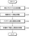
本発明のさらに他の一態様によるバッテリー管理方法は、バッテリーの容量及び電圧に基づいた微分電圧と容量との対応関係を示す微分プロファイルを生成する微分プロファイル生成段階と、微分プロファイルから複数のピークを検出する複数のピーク検出段階と、検出された複数のピークのそれぞれに対応する容量に基づいてバッテリーの退化度を算出するバッテリー退化度算出段階と、算出された退化度と予め設定された基準退化度とを比較した結果に応じてバッテリーに対する充電終了電圧の上限を設定する充電終了電圧上限設定段階と、を含む。A battery management method according to yet another aspect of the present invention includes a differential profile generating step of generating a differential profile showing the correspondence between differential voltage and capacity based on the capacity and voltage of the battery, a multiple peak detecting step of detecting multiple peaks from the differential profile, a battery degeneration degree calculating step of calculating the degree of degeneration of the battery based on the capacity corresponding to each of the multiple detected peaks, and a charging end voltage upper limit setting step of setting an upper limit of the charging end voltage for the battery according to a result of comparing the calculated degeneration degree with a preset reference degeneration degree.
本発明の一態様によれば、バッテリーの退化度を考慮してバッテリーに対する充電終了電圧の上限が適切に設定されるため、バッテリーの退化が加速することが防止されてバッテリーの期待寿命が増加することができる。According to one aspect of the present invention, the upper limit of the end-of-charge voltage for the battery is appropriately set taking into account the degree of degradation of the battery, thereby preventing the battery from deteriorating faster and increasing the expected lifespan of the battery.
また、バッテリーに対する充電終了電圧の上限がバッテリーの性能を過度に制限しない範囲で設定されるため、バッテリーの期待寿命が増加し、性能効率が向上することができる。In addition, the upper limit of the charging end voltage for the battery is set within a range that does not excessively limit the battery's performance, which increases the battery's expected lifespan and improves performance efficiency.
本発明の効果は上述した効果に制限されず、言及されていない本発明の他の効果は請求範囲の記載から当業者により明らかに理解されるだろう。The effects of the present invention are not limited to those described above, and other effects of the present invention not mentioned will be clearly understood by those skilled in the art from the description of the claims.
本明細書に添付される次の図面は、後述する発明の詳細な説明とともに本発明の技術的な思想をさらに理解させる役割をするものであり、本発明は図面に記載された事項だけに限定されて解釈されてはならない。The following drawings attached to this specification, together with the detailed description of the invention described below, serve to further understand the technical concept of the present invention, and the present invention should not be interpreted as being limited to only the matters depicted in the drawings.
本明細書及び特許請求の範囲において使われた用語や単語は通常的及び辞書的な意味に限定して解釈されてはならず、発明者自らは発明を最善の方法で説明するために用語の概念を適切に定義できるという原則に則して本発明の技術的な思想に応ずる意味及び概念で解釈されねばならない。The terms and words used in this specification and claims should not be interpreted in a limited manner based on their ordinary and dictionary meanings, but should be interpreted in a manner that reflects the technical concept of the present invention, based on the principle that the inventor himself can appropriately define the concept of the term in order to best describe the invention.
したがって、本明細書に記載された実施形態及び図面に示された構成は、本発明のもっとも望ましい一実施形態に過ぎず、本発明の技術的な思想のすべてを代弁するものではないため、本出願の時点においてこれらに代替できる多様な均等物及び変形例があり得ることを理解せねばならない。Therefore, it should be understood that the embodiment described in this specification and the configuration shown in the drawings are merely the most preferred embodiment of the present invention and do not represent the entire technical idea of the present invention, and that there may be various equivalents and modifications that can be substituted for them at the time of this application.
また、本発明の説明において、関連する公知の構成または機能についての具体的な説明が本発明の要旨を不明瞭にし得ると判断される場合、その詳細な説明を省略する。In addition, in describing the present invention, if it is determined that a detailed description of related publicly known configurations or functions may obscure the gist of the present invention, the detailed description will be omitted.
第1、第2などのように序数を含む用語は、多様な構成要素のうちのある一つをその他の要素と区別するために使われたものであり、これら用語によって構成要素が限定されることはない。Terms including ordinal numbers such as first, second, etc. are used to distinguish one of various components from the other components, and do not limit the components.
明細書の全体において、ある部分がある構成要素を「含む」とするとき、これは特に言及されない限り、他の構成要素を除外するものではなく、他の構成要素をさらに含み得ることを意味する。Throughout the specification, when a part "comprises" a certain component, this does not mean to exclude other components, but means that it may further include other components, unless otherwise specified.
さらに、明細書の全体において、ある部分が他の部分と「連結(接続)」されるとするとき、これは「直接的な連結(接続)」だけでなく、他の素子を介在した「間接的な連結(接続)」も含む。Furthermore, throughout the specification, when a part is referred to as being "connected" to another part, this includes not only a "direct connection" but also an "indirect connection" via other elements.
以下、添付された図面を参照して本発明の望ましい実施形態を詳しく説明する。Below, a preferred embodiment of the present invention will be described in detail with reference to the attached drawings.
図1は、本発明の一実施形態によるバッテリー管理装置100を概略的に示した図である。Figure 1 is a schematic diagram of a
図1を参照すると、本発明の一実施形態によるバッテリー管理装置100は、プロファイル生成部110及び制御部120を含む。Referring to FIG. 1, a
プロファイル生成部110は、バッテリーの容量及び電圧に対するバッテリー情報を取得するように構成され得る。The
ここで、バッテリーは、負極端子及び正極端子を備え、物理的に分離可能な一つの独立したセルを意味する。一例として、リチウムイオン電池またはリチウムポリマー電池をバッテリーとして見なし得る。Here, a battery refers to a single independent cell that has a negative terminal and a positive terminal and can be physically separated. As an example, a lithium ion battery or a lithium polymer battery may be considered a battery.
例えば、プロファイル生成部110は、バッテリーの容量と電圧との対応関係を示すバッテリープロファイルを取得し得る。すなわち、バッテリープロファイルにはバッテリーの容量と電圧とがマッピングされたバッテリー情報が含まれ得る。For example, the
プロファイル生成部110は、容量及び電圧に基づいた微分電圧と容量との対応関係を示す微分プロファイルPdを生成するように構成され得る。The
ここで、微分電圧は、バッテリー情報に含まれた電圧を容量で微分した値であって、「dV/dQ」で表され得る。すなわち、微分電圧は、容量に対する電圧の瞬間変化率を示す値であり得る。微分プロファイルPdは、図2の実施形態を挙げて説明する。Here, the differential voltage is a value obtained by differentiating the voltage included in the battery information by the capacity, and can be expressed as "dV/dQ." That is, the differential voltage can be a value indicating the instantaneous rate of change of the voltage with respect to the capacity. The differential profile Pd will be described with reference to the embodiment shown in FIG. 2.
図2は、本発明の一実施形態による微分プロファイルPd及び基準プロファイルPrefを概略的に示した図である。Figure 2 is a schematic diagram showing a differential profile Pd and a reference profile Pref according to one embodiment of the present invention.
図2の実施形態において、プロファイル生成部110は、取得されたバッテリー情報に基づいて、容量と微分電圧との対応関係を示す微分プロファイルPdを生成し得る。In the embodiment of FIG. 2, the
そして、図2の実施形態において、基準プロファイルPrefは、BOLバッテリーに対する容量と微分電圧との対応関係を示すプロファイルであり得る。また、図2の実施形態において、容量はBOLバッテリーの容量を基準にする相対容量であり得る。In the embodiment of FIG. 2, the reference profile Pref may be a profile showing the correspondence between capacity and differential voltage for the BOL battery. Also, in the embodiment of FIG. 2, the capacity may be a relative capacity based on the capacity of the BOL battery.
制御部120は、プロファイル生成部110から微分プロファイルPdを取得するように構成され得る。The
例えば、制御部120とプロファイル生成部110とは、通信可能に接続され得る。プロファイル生成部110は生成した微分プロファイルPdを制御部120に送信し、制御部120はプロファイル生成部110から微分プロファイルPdを受信し得る。For example, the
制御部120は、取得された微分プロファイルPdから複数のピークを検出するように構成され得る。The
ここで、ピークは、微分プロファイルPdにおいて下方に向かって凸状の概形を有する地点であり得る。すなわち、ピークは、容量に対する微分電圧の変化率が0である地点であって、ピークを基準にして低容量側は変化率が負であり、高容量側は変化率が正であり得る。Here, the peak may be a point in the differential profile Pd that has a generally downwardly convex shape. In other words, the peak is a point where the rate of change of the differential voltage with respect to the capacitance is 0, and the rate of change on the low capacitance side relative to the peak may be negative, and the rate of change on the high capacitance side may be positive.
具体的には、制御部120は、複数のピークのうちの基準プロファイルPrefの第1容量区間RLに含まれたピークを第1ターゲットピークTP1として検出するように構成され得る。Specifically, the
例えば、第1容量区間RLは、基準プロファイルPrefの全体容量区間のうちの低容量区間を意味し得る。図2の実施形態において、0以上0.5未満の容量区間が第1容量区間RLに予め設定され得る。そして、制御部120は、第1容量区間RLに含まれた複数のピークのうちの対応する容量が最も大きいピークを第1ターゲットピークTP1として検出し得る。検出された第1ターゲットピークTP1は、第1ターゲット容量TQ1に対応するピークであり得る。For example, the first capacity section RL may refer to a low capacity section of the entire capacity section of the reference profile Pref. In the embodiment of FIG. 2, a capacity section greater than or equal to 0 and less than 0.5 may be preset as the first capacity section RL. Then, the
また、制御部120は、複数のピークのうちの基準プロファイルPrefの第2容量区間RHに含まれたピークを第2ターゲットピークTP2として検出するように構成され得る。The
例えば、第2容量区間RHは、基準プロファイルPrefの全体容量区間のうちの高容量区間を意味し得る。図2の実施形態において、0.5以上1以下の容量区間が第2容量区間RHに予め設定され得る。そして、制御部120は、第2容量区間RHに含まれた複数のピークのうちの対応する容量が最も大きいピークを第2ターゲットピークTP2として検出し得る。検出された第2ターゲットピークTP2は、第2ターゲット容量TQ2に対応するピークであり得る。For example, the second capacity range RH may refer to a high capacity range among the entire capacity range of the reference profile Pref. In the embodiment of FIG. 2, a capacity range of 0.5 to 1 may be preset as the second capacity range RH. Then, the
すなわち、図2の実施形態に含まれた微分プロファイルPd及び基準プロファイルPrefは、BOLバッテリーの全体容量を基準にして容量区間が0~1に正規化され得る。したがって、0以上0.5未満の容量区間は低容量区間であって第1容量区間RLに設定され、0.5以上1以下の容量区間は高容量区間であって第2容量区間RHに設定され得る。That is, the differential profile Pd and the reference profile Pref included in the embodiment of FIG. 2 may be normalized to a capacity range of 0 to 1 based on the total capacity of the BOL battery. Therefore, the capacity range of 0 to less than 0.5 may be set as a low capacity range, which is the first capacity range RL, and the capacity range of 0.5 to 1 may be set as a high capacity range, which is the second capacity range RH.
制御部120は、検出された複数のピークのそれぞれに対応する容量に基づいてバッテリーの退化度を算出するように構成され得る。The
具体的には、制御部120は、第1ターゲットピークTP1に対応する第1ターゲット容量TQ1と第2ターゲットピークTP2に対応する第2ターゲット容量TQ2との間の容量差を算出するように構成され得る。例えば、図2の実施形態において、制御部120は「TQ2-TQ1」の数式を計算して第1ターゲット容量TQ1と第2ターゲット容量TQ2との間の容量差を算出し得る。Specifically, the
そして、制御部120は、算出された容量差及び予め設定された基準プロファイルPrefに対する基準容量差に基づいて退化度を算出するように構成され得る。The
ここで、基準容量差は、基準プロファイルPrefにおいて、第1ターゲットピークTP1に対応する第1基準ピークRP1の第1基準容量RQ1と第2ターゲットピークTP2に対応する第2基準ピークRP2の第2基準容量RQ2との間の容量差として設定され得る。Here, the reference capacity difference can be set as the capacity difference between the first reference capacity RQ1 of the first reference peak RP1 corresponding to the first target peak TP1 and the second reference capacity RQ2 of the second reference peak RP2 corresponding to the second target peak TP2 in the reference profile Pref.
例えば、図2の実施形態において、基準プロファイルPrefには第1基準ピークRP1及び第2基準ピークRP2が含まれ得る。第1基準ピークRP1は、BOLバッテリーに対するピークであって、第1ターゲットピークTP1に対応するピークであり得る。第2基準ピークRP2は、BOLバッテリーに対するピークであって、第2ターゲットピークTP2に対応するピークであり得る。For example, in the embodiment of FIG. 2, the reference profile Pref may include a first reference peak RP1 and a second reference peak RP2. The first reference peak RP1 may be a peak for the BOL battery and may correspond to the first target peak TP1. The second reference peak RP2 may be a peak for the BOL battery and may correspond to the second target peak TP2.
そして、制御部120は、予め設定された基準容量差を取得するか、または、基準プロファイルPrefに基づいて基準容量差を直接算出し得る。例えば、制御部120は「RQ2-RQ1」の数式を計算して基準容量差を直接算出してもよい。The
制御部120は、基準容量差に対する容量差の比率を計算し、バッテリーの退化度を算出し得る。具体的には、制御部120は、下記の数式1に基づいてバッテリーの退化度を算出し得る。The
[数1]
D = {1 - (TD ÷ RD)} × 100 … 数式1 [Equation 1]
D = {1 - (TD ÷ RD)} × 100 … Formula 1
ここで、Dはバッテリーの退化度であり、TDは第1ターゲット容量TQ1と第2ターゲット容量TQ2との間の容量差である。RDは、第1基準容量RQ1と第2基準容量RQ2との間の基準容量差であり得る。そして、100は算出される退化度の単位を[%]で表すために乗ずる定数であり得る。Here, D is the degree of degradation of the battery, TD is the capacity difference between the first target capacity TQ1 and the second target capacity TQ2, RD can be the reference capacity difference between the first reference capacity RQ1 and the second reference capacity RQ2, and 100 can be a constant by which to multiply the calculated degree of degradation in units of [%].
例えば、図2の実施形態において、第1ターゲット容量TQ1と第2ターゲット容量TQ2との間の容量差TDが0.594であり、第1基準容量RQ1と第2基準容量RQ2との間の基準容量差RDが0.607であると仮定する。制御部120は、上記の数式1に容量差TD及び基準容量差RDを代入して、バッテリーの退化度Dを2.14%と算出し得る。For example, in the embodiment of FIG. 2, assume that the capacity difference TD between the first target capacity TQ1 and the second target capacity TQ2 is 0.594, and the reference capacity difference RD between the first reference capacity RQ1 and the second reference capacity RQ2 is 0.607. The
制御部120は、算出された退化度と予め設定された基準退化度とを比較した結果に応じてバッテリーに対する充電終了電圧の上限を設定するように構成され得る。The
望ましくは、バッテリーに対する充電終了電圧の上限は、BOLバッテリーのSOC(State of Charge:充電状態)100%に対応する電圧として予め設定され得る。例えば、バッテリーの充電終了電圧の上限は4.2Vに予め設定され得る。しかし、バッテリーの退化度を考慮せず、充電終了電圧の上限が4.2Vに維持されれば、過充電が繰り返されることでバッテリーの寿命が急激に減少するおそれがある。Preferably, the upper limit of the end-of-charge voltage for the battery can be preset as a voltage corresponding to a 100% SOC (State of Charge) of the BOL battery. For example, the upper limit of the end-of-charge voltage for the battery can be preset to 4.2V. However, if the upper limit of the end-of-charge voltage is maintained at 4.2V without taking into account the degree of degradation of the battery, repeated overcharging may result in a rapid reduction in the battery's lifespan.
したがって、本発明の一実施形態によるバッテリー管理装置100は、算出されたバッテリーの退化度及び基準退化度に基づいてバッテリーに対する充電終了電圧の上限を適切に設定することで、バッテリーの退化が加速することを防止してバッテリーの期待寿命を増加させることができる。Therefore, the
一方、バッテリー管理装置100に備えられた制御部120は、本発明で行われる多様な制御ロジックを実行するため、当業界に知られたプロセッサ、ASIC(Application-Specific Integrated Circuit、特定用途向け集積回路)、他のチップセット、論理回路、レジスタ、通信モデム、データ処理装置などを選択的に含み得る。また、制御ロジックがソフトウェアとして具現されるとき、制御部120は、プログラムモジュールの集合として具現され得る。このとき、プログラムモジュールはメモリに保存され、制御部120によって実行され得る。メモリは、制御部120の内部または外部に備えられ得、周知の多様な手段で制御部120に接続され得る。Meanwhile, the
また、バッテリー管理装置100は、保存部130をさらに含み得る。保存部130は、バッテリー管理装置100の各構成要素が動作及び機能を行うのに必要なデータ、若しくは、プログラムまたは動作及び機能が行われる過程で生成されるデータなどを保存し得る。保存部130は、データを記録、消去、更新及び読出できると知られた公知の情報記録手段であれば、その種類に特に制限がない。一例として、情報記録手段にはRAM、フラッシュ(登録商標)メモリ、ROM、EEPROM、レジスタなどが含まれ得る。また、保存部130は、制御部120によって実行可能なプロセスが定義されたプログラムコードを保存し得る。The
例えば、保存部130は、バッテリーの電圧と容量との対応関係を示すバッテリー情報を保存し得る。また、保存部130は、BOLバッテリーの電圧と容量との対応関係を示すBOLバッテリー情報を保存し得る。そして、プロファイル生成部110は、保存部130にアクセスしてバッテリー情報を取得し、取得されたバッテリー情報に基づいてバッテリーに対する微分プロファイルPdを生成し得る。For example, the
また、保存部130は、プロファイル生成部110によって生成された微分プロファイルPdを保存し得る。制御部120は、プロファイル生成部110から微分プロファイルPdを直接受信してもよく、保存部130にアクセスして保存された微分プロファイルPdを取得してもよい。また、制御部120は、保存部130にアクセスしてバッテリー情報及びBOLバッテリー情報も取得し得る。The
制御部120は、算出された退化度が基準退化度未満であれば、充電終了電圧の上限をバッテリーに対して予め設定されたBOL電圧に設定するように構成され得る。The
ここで、BOL電圧は、BOLバッテリーに対して設定された充電終了電圧の上限であり得る。すなわち、制御部120は、算出されたバッテリーの退化度が基準退化度未満であれば、バッテリーの性能効率を最大に維持するため、バッテリーに対する充電終了電圧の上限を変更しなくてもよい。Here, the BOL voltage may be the upper limit of the end-of-charge voltage set for the BOL battery. That is, if the calculated deterioration degree of the battery is less than the reference deterioration degree, the
例えば、算出されたバッテリーの退化度が2%であり、基準退化度が5%であると仮定する。この場合、制御部120は、バッテリーに対する充電終了電圧の上限を変更しなくてもよい。すなわち、バッテリーの充電終了電圧の上限は、BOLバッテリーの充電終了電圧の上限に維持され得る。For example, assume that the calculated battery degradation level is 2% and the reference degradation level is 5%. In this case, the
制御部120は、算出された退化度が基準退化度以上であれば、充電終了電圧の上限を予め設定された基準電圧以下に設定するように構成され得る。The
ここで、基準電圧は、BOL電圧未満であり得る。具体的には、基準電圧は、基準プロファイルPrefにおいて、第2ターゲットピークTP2に対応する第2基準ピークRP2に対応する電圧に設定され得る。例えば、基準電圧は、第2基準ピークRP2の第2基準容量RQ2に対応する電圧に設定され得る。Here, the reference voltage may be less than the BOL voltage. Specifically, the reference voltage may be set to a voltage corresponding to the second reference peak RP2, which corresponds to the second target peak TP2, in the reference profile Pref. For example, the reference voltage may be set to a voltage corresponding to the second reference capacity RQ2 of the second reference peak RP2.
例えば、算出されたバッテリーの退化度が5%であり、基準退化度が5%であると仮定する。この場合、制御部120は、バッテリーに対する充電終了電圧の上限を第2基準容量RQ2に対応する電圧に設定し得る。For example, assume that the calculated degree of degradation of the battery is 5% and the reference degree of degradation is 5%. In this case, the
具体的には、制御部120は、BOLバッテリーに対する電圧と容量との対応関係を示すBOLバッテリー情報を予め取得して保存しているか、または、保存部130にアクセスして取得し得る。そして、制御部120は、BOLバッテリー情報から第2基準容量RQ2に対応する電圧を選択し、選択された電圧を充電終了電圧の上限として設定し得る。Specifically, the
図2の実施形態において、第2基準ピークRP2は、BOLバッテリーの相転移(phase transition)が終了し、相平衡(phase equilibrium)が始まる地点であり得る。同様に、第2ターゲットピークTP2は、現在バッテリーの相転移が終了し、相平衡が始まる地点であり得る。In the embodiment of FIG. 2, the second reference peak RP2 may be the point where the phase transition of the BOL battery ends and phase equilibrium begins. Similarly, the second target peak TP2 may be the point where the phase transition of the current battery ends and phase equilibrium begins.
もし、第2ターゲット容量TQ2を基準にしてバッテリーの充電終了電圧の上限を設定する場合、設定された充電終了電圧の上限はバッテリーの退化による過電圧に影響を受け得る。すなわち、MOL(Middle of life)状態のバッテリーに対する過電圧によって、第2ターゲット容量TQ2に対応する電圧とMOLバッテリーの相平衡が始まる実際電圧とには誤差が存在し得る。If the upper limit of the battery's end-of-charge voltage is set based on the second target capacity TQ2, the upper limit of the set end-of-charge voltage may be affected by overvoltage caused by battery degradation. That is, due to overvoltage on a battery in the MOL (middle of life) state, there may be an error between the voltage corresponding to the second target capacity TQ2 and the actual voltage at which phase equilibrium of the MOL battery begins.
例えば、図2の実施形態において、理想的には第2基準容量RQ2に対応する電圧と第2ターゲット容量TQ2に対応する電圧とが同一であり得る。しかし、実際に運用されるバッテリーは、退化による過電圧の影響を受けるため、第2ターゲット容量TQ2に対応する電圧は第2基準容量RQ2に対応する電圧と異なり得る。具体的には、第2ターゲット容量TQ2に対応する電圧が第2基準容量RQ2に対応する電圧よりも大きくなり得る。したがって、第2ターゲット容量TQ2を基準にして充電終了電圧の上限を設定する場合、現在バッテリーの相転移が終了する地点(相平衡が始まる地点)に対応する電圧よりも高電圧に充電終了電圧の上限が設定され得る。すなわち、バッテリーの相平衡が進行している電圧が充電終了電圧の上限として設定される可能性がある。この場合、バッテリーは相平衡が進行する電圧まで充電され得、これによってバッテリーの退化が加速され得る。For example, in the embodiment of FIG. 2, ideally, the voltage corresponding to the second reference capacity RQ2 and the voltage corresponding to the second target capacity TQ2 may be the same. However, since a battery actually operated is affected by overvoltage due to degradation, the voltage corresponding to the second target capacity TQ2 may differ from the voltage corresponding to the second reference capacity RQ2. Specifically, the voltage corresponding to the second target capacity TQ2 may be greater than the voltage corresponding to the second reference capacity RQ2. Therefore, when setting the upper limit of the charging end voltage based on the second target capacity TQ2, the upper limit of the charging end voltage may be set to a voltage higher than the voltage corresponding to the point where the phase transition of the battery currently ends (the point where phase equilibrium begins). In other words, the voltage at which phase equilibrium of the battery is progressing may be set as the upper limit of the charging end voltage. In this case, the battery may be charged to the voltage at which phase equilibrium is progressing, which may accelerate the degradation of the battery.
したがって、制御部120は、バッテリーの退化による過電圧の影響を考慮してバッテリーの期待寿命を増加させるため、バッテリーの充電終了電圧の上限をBOLバッテリーの相転移終了電圧(第2基準容量RQ2に対応する電圧)に設定し得る。Therefore, the
本発明の一実施形態によるバッテリー管理装置100は、BOLバッテリーに対する第2基準容量RQ2に対応する電圧をバッテリーの充電終了電圧の上限として設定することで、バッテリーに対する急激な退化を防止するとともに、バッテリーの性能効率を最大限に維持することができる。すなわち、バッテリーに対する充電終了電圧の上限がバッテリーの性能を過度に制限しない範囲で設定されるため、バッテリーの期待寿命が増加し、性能効率が向上することができる。The
一方、このような第2基準ピークRP2及び第2ターゲットピークTP2は、バッテリーの正極材に含まれるニッケル(Ni)の含量が高い場合(例えば、80%以上)だけでなく、ニッケルの含量が低い場合(例えば、80%未満)にも現れ得る。これは、基準プロファイルPrefが容量Qと微分電圧dV/dQとの間の対応関係を示すプロファイルであって、容量に基づいて電圧の瞬間変化率を示すプロファイルであるためである。Meanwhile, such second reference peak RP2 and second target peak TP2 may appear not only when the nickel (Ni) content in the battery positive electrode material is high (e.g., 80% or more), but also when the nickel content is low (e.g., less than 80%). This is because the reference profile Pref is a profile that indicates the correspondence between the capacity Q and the differential voltage dV/dQ, and is a profile that indicates the instantaneous rate of change of voltage based on the capacity.
例えば、図2の実施形態において、微分プロファイルPd及び基準プロファイルPrefは、正極材に含まれたニッケルの含量が60%であり、負極材は黒鉛であるバッテリーに対するプロファイルである。For example, in the embodiment of FIG. 2, the differential profile Pd and the reference profile Pref are profiles for a battery in which the nickel content in the positive electrode material is 60% and the negative electrode material is graphite.
基準プロファイルPrefとは反対に、電圧Vと微分容量dQ/dVとの間の対応関係を示すプロファイルでは、ニッケル含量が低い場合(例えば、80%未満)、第2基準ピークRP2及び第2ターゲットピークTP2に対応するピークが現れないこともある。第2基準ピークRP2及び第2ターゲットピークTP2が現れない場合、バッテリーの退化度を算出し難いため、バッテリーに対する充電終了電圧の上限が適切に設定されないおそれがある。In contrast to the reference profile Pref, in the profile showing the correspondence between the voltage V and the differential capacity dQ/dV, when the nickel content is low (e.g., less than 80%), the peaks corresponding to the second reference peak RP2 and the second target peak TP2 may not appear. If the second reference peak RP2 and the second target peak TP2 do not appear, it is difficult to calculate the degree of degradation of the battery, and therefore the upper limit of the end-of-charge voltage for the battery may not be set appropriately.
したがって、本発明の一実施形態では、バッテリーの正極材に含まれたニッケル含量が低い場合にも、バッテリーに対する充電終了電圧の上限を適切に設定することができる。Therefore, in one embodiment of the present invention, even if the nickel content in the battery's positive electrode material is low, the upper limit of the end-of-charge voltage for the battery can be appropriately set.
制御部120は、算出された退化度が基準退化度以上である場合、算出された退化度と基準退化度との間の退化差を算出するように構成され得る。The
例えば、制御部120は、算出された退化度と基準退化度との間の差を計算して退化差を算出し得る。For example, the
[数2]
DV=D-RD … 数式2 [Equation 2]
DV=D-RD … Equation 2
ここで、DVは退化差であり、Dは数式1によって算出されたバッテリーの退化度であり、RDは基準退化度である。Here, DV is the degradation difference, D is the degree of degradation of the battery calculated by Equation 1, and RD is the reference degree of degradation.
制御部120は、基準電圧から退化差に比例するように減少された電圧を充電終了電圧の上限として設定するように構成され得る。The
例えば、算出されたバッテリーの退化度が6%であり、基準退化度が5%であり、第2基準容量RQ2に対応する基準電圧が4.0Vであると仮定する。For example, assume that the calculated battery degradation level is 6%, the reference degradation level is 5%, and the reference voltage corresponding to the second reference capacity RQ2 is 4.0 V.
制御部120は、「バッテリーの退化度(6%)-基準退化度(5%)」を計算して退化差を1%と算出し得る。そして、制御部120は、基準電圧から退化差(1%)に比例するように減少された3.96Vをバッテリーに対する充電終了電圧の上限として設定し得る。The
すなわち、制御部120は、バッテリーが退化するほど充電終了電圧の上限を減少させることで、バッテリーの退化が急激に進行することを防止するとともに、バッテリーの性能効率を高く維持することができる。In other words, the
制御部120は、算出された退化差が予め設定された臨界差以上である場合、バッテリーをEOL状態と診断するように構成され得る。The
例えば、臨界差は15%に設定され得る。すなわち、バッテリーの退化度が基準退化度よりも臨界差以上に大きい場合、制御部120は、バッテリーを不用バッテリー(EOLバッテリー)と診断し得る。For example, the critical difference may be set to 15%. That is, if the deterioration level of the battery is greater than the reference deterioration level by more than the critical difference, the
すなわち、本発明の一実施形態によるバッテリー管理装置100は、バッテリーがBOLバッテリーよりも臨界差以上に退化した場合、バッテリーをEOL状態と診断することで、退化したバッテリーが運用されることで発生する発火または爆発などの問題を予め防止することができる。In other words, the
本発明によるバッテリー管理装置100は、BMS(Battery Management System、バッテリー管理システム)に適用可能である。すなわち、本発明によるBMSは、上述したバッテリー管理装置100を含み得る。このような構成において、バッテリー管理装置100の各構成要素の少なくとも一部は、従来のBMSに含まれた構成の機能を補完または追加することで具現され得る。例えば、バッテリー管理装置100のプロファイル生成部110、制御部120及び保存部130は、BMSの構成要素として具現され得る。The
また、本発明によるバッテリー管理装置100は、バッテリーパックに備えられ得る。すなわち、本発明によるバッテリーパックは、上述したバッテリー管理装置100及び一つ以上のバッテリーセルを含み得る。また、バッテリーパックは、電装品(リレー、ヒューズなど)及びケースなどをさらに含み得る。The
図3は、本発明の他の一実施形態によるバッテリーパック1の例示的構成を概略的に示した図である。Figure 3 is a schematic diagram illustrating an exemplary configuration of a battery pack 1 according to another embodiment of the present invention.
測定部200は、第1センシングラインSL1、第2センシングラインSL2及び第3センシングラインSL3に接続され得る。The
具体的には、第1センシングラインSL1は、バッテリーセルBの正極と測定部200とに接続され得る。また、第2センシングラインSL2は、バッテリーセルBの負極と測定部200とに接続され得る。測定部200は、第1センシングラインSL1を通じて測定されたバッテリーセルBの正極電圧と第2センシングラインSL2を通じて測定されたバッテリーセルBの負極電圧との差を計算し、バッテリーセルBの電圧を測定し得る。Specifically, the first sensing line SL1 may be connected to the positive electrode of the battery cell B and the
また、測定部200は、第3センシングラインSL3と接続された電流測定ユニットAを通じてバッテリーセルBの充電電流及び/または放電電流を測定し得る。例えば、電流測定ユニットAは、シャント抵抗または電流計であり得る。The
測定部200によって測定されたバッテリーセルBの電圧及び電流に対するバッテリー情報は、バッテリー管理装置100に送信され得る。具体的には、プロファイル生成部110は、測定部200からバッテリーセルBのバッテリー情報を受信し得る。そして、プロファイル生成部110は、受信したバッテリーセルBの電圧及び電流に基づいてバッテリーセルBの容量と微分電圧との対応関係を示す微分プロファイルPdを生成し得る。また、測定部200によって測定されたバッテリーセルBのバッテリー情報は、保存部130に保存され得る。Battery information regarding the voltage and current of battery cell B measured by the
図4は、本発明のさらに他の一実施形態によるバッテリー管理方法を概略的に示した図である。Figure 4 is a schematic diagram illustrating a battery management method according to yet another embodiment of the present invention.
望ましくは、バッテリー管理方法の各段階は、バッテリー管理装置100によって実行できる。以下では、上述した説明と重なる内容は省略するか又は簡単に説明する。Preferably, each step of the battery management method can be performed by the
図4を参照すると、バッテリー管理方法は、微分プロファイル生成段階S100、複数のピーク検出段階S200、バッテリー退化度算出段階S300、及び充電終了電圧上限設定段階S400を含む。Referring to FIG. 4, the battery management method includes a differential profile generating step S100, a plurality of peak detection steps S200, a battery degradation degree calculation step S300, and a charging end voltage upper limit setting step S400.
微分プロファイル生成段階S100は、バッテリーの容量及び電圧に基づいた微分電圧と容量との対応関係を示す微分プロファイルPdを生成する段階であって、プロファイル生成部110によって実行できる。The differential profile generation step S100 is a step of generating a differential profile Pd that indicates the correspondence between the differential voltage and capacity based on the capacity and voltage of the battery, and can be executed by the
例えば、図2の実施形態において、プロファイル生成部110は、バッテリーの容量と微分電圧との対応関係を示す微分プロファイルPdを生成し得る。For example, in the embodiment of FIG. 2, the
複数のピーク検出段階S200は、微分プロファイルPdから複数のピークを検出する段階であって、制御部120によって実行できる。The multiple peak detection step S200 is a step of detecting multiple peaks from the differential profile Pd, and can be executed by the
例えば、図2の実施形態において、制御部120は、第1容量区間RLから第1ターゲットピークTP1を検出し、第2容量区間RHから第2ターゲットピークTP2を検出し得る。ここで、第1容量区間RLは、正規化された容量区間において0以上0.5未満の容量区間であり、第2容量区間RHは、正規化された容量区間において0.5以上1以下の容量区間であり得る。For example, in the embodiment of FIG. 2, the
バッテリー退化度算出段階S300は、検出された複数のピークのそれぞれに対応する容量に基づいてバッテリーの退化度を算出する段階であって、制御部120によって実行できる。The battery degradation degree calculation step S300 is a step of calculating the battery degradation degree based on the capacity corresponding to each of the detected multiple peaks, and can be executed by the
例えば、図2の実施形態において、制御部120は、第1基準容量RQ1、第2基準容量RQ2、第1ターゲット容量TQ1及び第2ターゲット容量TQ2に基づいてバッテリーの退化度を算出し得る。具体的には、制御部120は、上記の数式1に基準容量差(第1基準容量RQ1と第2基準容量RQ2との間の容量差)及び容量差(第1ターゲット容量TQ1と第2ターゲット容量TQ2との間の容量差)を代入してバッテリーの退化度を算出し得る。For example, in the embodiment of FIG. 2, the
充電終了電圧上限設定段階S400は、算出された退化度と予め設定された基準退化度とを比較した結果に応じてバッテリーに対する充電終了電圧の上限を設定する段階であって、制御部120によって実行できる。The charging end voltage upper limit setting step S400 is a step of setting an upper limit of the charging end voltage for the battery according to the result of comparing the calculated degradation degree with a preset reference degradation degree, and can be executed by the
例えば、算出された退化度が基準退化度未満である場合、制御部120は、バッテリーに対する充電終了電圧の上限をBOLバッテリーに対する充電終了電圧の上限に設定し得る。For example, if the calculated degree of degradation is less than the reference degree of degradation, the
他の例として、算出された退化度が基準退化度以上である場合、制御部120は、バッテリーに対する充電終了電圧の上限を基準電圧以下に設定し得る。図2の実施形態において、基準電圧は、第2基準容量RQ2に対応する電圧であり得る。As another example, if the calculated degree of degradation is equal to or greater than the reference degree of degradation, the
また、制御部120は、算出された退化度と基準退化度との間の退化差を算出し得る。そして、制御部120は、基準電圧から退化差に比例するように減少された電圧を充電終了電圧の上限として設定し得る。The
上述した本発明の実施形態は、装置及び方法のみによって具現されるものではなく、本発明の実施形態の構成に対応する機能を実現するプログラムまたはそのプログラムが記録された記録媒体を通じても具現され得、このような具現は上述した実施形態の記載から当業者であれば容易に具現できるであろう。The above-described embodiments of the present invention may be realized not only by devices and methods, but also by a program that realizes functions corresponding to the configurations of the embodiments of the present invention or a recording medium on which the program is recorded. Such realization would be easily possible for a person skilled in the art based on the description of the above-described embodiments.
以上のように、本発明を限定された実施形態と図面によって説明したが、本発明はこれに限定されるものではなく、本発明の属する技術分野で通常の知識を持つ者によって本発明の技術思想と特許請求の範囲の均等範囲内で多様な修正及び変形が可能であることは言うまでもない。As described above, the present invention has been described using limited embodiments and drawings, but the present invention is not limited thereto, and it goes without saying that various modifications and variations are possible within the scope of the technical concept of the present invention and the scope of the claims by a person with ordinary skill in the art to which the present invention pertains.
また、上述した本発明は、本発明が属する技術分野で通常の知識を持つ者により、本発明の技術的思想を逸脱しない範囲内で様々な置換、変形及び変更が可能であって、上述した実施形態及び添付の図面によって限定されるものではなく、多様な変形のため各実施形態の全部または一部が選択的に組み合わせられて構成され得る。Furthermore, the present invention described above may be variously substituted, modified, and altered by a person having ordinary knowledge in the technical field to which the present invention pertains, without departing from the technical concept of the present invention, and is not limited to the above-described embodiments and the accompanying drawings, but may be configured by selectively combining all or part of each embodiment for various modifications.
1:バッテリーパック
100:バッテリー管理装置
110:プロファイル生成部
120:制御部
130:保存部
200:測定部 1: Battery pack 100: Battery management device 110: Profile generation unit 120: Control unit 130: Storage unit 200: Measurement unit
Claims (9)
Translated fromJapanese前記プロファイル生成部から前記微分プロファイルを取得し、取得された微分プロファイルから複数のピークを検出し、検出された複数のピークのそれぞれに対応する容量に基づいて前記バッテリーの退化度を算出し、算出された退化度と予め設定された基準退化度とを比較した結果に応じて前記バッテリーに対する充電終了電圧の上限を設定する制御部と、を含み、
前記制御部は、
前記算出された退化度が前記基準退化度以上である場合、前記充電終了電圧の上限を予め設定された基準電圧以下に設定し、
前記基準電圧は、
前記複数のピークのうちのいずれかのピークに対応する基準ピークの電圧に予め設定され、
前記制御部は、
前記微分プロファイルから第1ターゲットピーク及び第2ターゲットピークを検出し、
前記第1ターゲットピークに対応する第1ターゲット容量と前記第2ターゲットピークに対応する第2ターゲット容量との容量差を算出し、
算出された容量差及び予め設定された基準プロファイルに対する基準容量差に基づいて前記退化度を算出し、
前記基準電圧は、
前記基準プロファイルにおいて、前記第2ターゲットピークに対応する第2基準ピークに対応する電圧に設定されている、バッテリー管理装置。a profile generating unit that acquires battery information regarding a capacity and a voltage of a battery, and generates a differential profile that indicates a correspondence relationship between the capacity and a differential voltage based on the capacity and the voltage;
a control unit that acquires the differential profile from the profile generating unit, detects a plurality of peaks from the acquired differential profile, calculates a degree of degradation of the battery based on a capacity corresponding to each of the detected plurality of peaks, and sets an upper limit of a charge end voltage for the battery in accordance with a result of comparing the calculated degree of degradation with a preset reference degree of degradation,
The control unit is
If the calculated degradation degree is equal to or greater than the reference degradation degree, the upper limit of the charge end voltage is set to a predetermined reference voltage or less;
The reference voltage is
a voltage of a reference peak corresponding to any one of the plurality of peaks is preset;
The control unit is
Detecting a first target peak and a second target peak from the differential profile;
Calculating a capacity difference between a first target capacity corresponding to the first target peak and a second target capacity corresponding to the second target peak;
Calculating the degree of degeneration based on the calculated capacitance difference and a reference capacitance difference with respect to a preset reference profile;
The reference voltage is
The battery management deviceis set to a voltage corresponding to a second reference peak in the reference profile, the second reference peak corresponding to the second target peak .
前記複数のピークのうちの前記基準プロファイルの第1容量区間に含まれたピークを前記第1ターゲットピークとして検出し、
前記複数のピークのうちの前記基準プロファイルの第2容量区間に含まれたピークを前記第2ターゲットピークとして検出する、請求項1に記載のバッテリー管理装置。 The control unit is
Detecting a peak included in a first volume section of the reference profile as the first target peak from among the plurality of peaks;
The battery management device of claim1 , wherein a peak included in a second capacity section of the reference profile among the plurality of peaks is detected as the second target peak.
前記基準プロファイルにおいて、前記第1ターゲットピークに対応する第1基準ピークの第1基準容量と前記第2ターゲットピークに対応する第2基準ピークの第2基準容量との容量差として設定されている、請求項1または2に記載のバッテリー管理装置。 The reference capacity difference is
3. The battery management device of claim 1, wherein in the reference profile, a capacity difference is set between a first reference capacity of a first reference peak corresponding to the first target peak and a second reference capacity of asecond reference peak corresponding to thesecond target peak.
前記算出された退化度が前記基準退化度未満である場合、前記充電終了電圧の上限を前記バッテリーに対して予め設定されたBOL電圧以下に設定する、請求項1から3のいずれか一項に記載のバッテリー管理装置。 The control unit is
4. The battery management device according to claim1 , further comprising: a first charging voltage limit setting unit configured to set a first charging voltage limit for the battery when the calculated deterioration degree is less than the reference deterioration degree;
前記第2基準ピークの第2基準容量に対応する電圧に設定されている、請求項4に記載のバッテリー管理装置。 The reference voltage is
5. The battery management device according to claim4 , wherein the second reference peak is set to a voltage corresponding to a second reference capacity.
前記算出された退化度が前記基準退化度以上である場合、前記算出された退化度と前記基準退化度との間の退化差を算出し、前記基準電圧から前記退化差に比例するように減少された電圧を前記充電終了電圧の上限として設定する、請求項4または5に記載のバッテリー管理装置。 The control unit is
6. The battery management device according to claim 4, further comprising: a degeneration difference between the calculated degeneration degreeand the reference degeneration degree when the calculated degeneration degree is equal to or greater than the reference degeneration degree; and a voltage reduced from the reference voltage in proportion to the degeneration difference is set as the upper limit of the charging end voltage.
前記算出された退化差が予め設定された臨界差以上である場合、前記バッテリーをEOL状態と診断する、請求項4から6のいずれか一項に記載のバッテリー管理装置。 The control unit is
The battery management device of claim4 , further comprising: a step of diagnosing the battery as being in an EOL state when the calculated degradation difference is equal to or greater than a preset critical difference.
前記微分プロファイルから第1ターゲットピーク及び第2ターゲットピークを含む複数のピークを検出する複数のピーク検出段階と、
検出された複数のピークのそれぞれに対応する容量に基づいて前記バッテリーの退化度を算出するバッテリー退化度算出段階と、
算出された退化度と予め設定された基準退化度とを比較した結果に応じて前記バッテリーに対する充電終了電圧の上限を設定する充電終了電圧上限設定段階と、を含み、
前記充電終了電圧上限設定段階は、
前記算出された退化度が前記基準退化度以上である場合、前記充電終了電圧の上限を予め設定された基準電圧以下に設定することを含み、
前記基準電圧は、
前記複数のピークのうちのいずれかのピークに対応する基準ピークの電圧に予め設定され、
前記バッテリー退化度算出段階は、
前記第1ターゲットピークに対応する第1ターゲット容量と前記第2ターゲットピークに対応する第2ターゲット容量との容量差を算出する段階と、
算出された容量差及び予め設定された基準プロファイルに対する基準容量差に基づいて前記退化度を算出する段階と、を含み、
前記基準電圧は、
前記基準プロファイルにおいて、前記第2ターゲットピークに対応する第2基準ピークに対応する電圧に設定されている、
バッテリー管理方法。 generating a differential profile indicating a correspondence relationship between a differential voltage and the capacity based on the capacity and voltage of the battery;
a multiple peak detection step of detecting multiple peaksincluding a first target peak and a second target peak from the differential profile;
calculating a degree of degradation of the battery based on a capacity corresponding to each of the detected peaks;
and setting an upper limit of a charging end voltage of the battery according to a result of comparing the calculated deterioration degree with a preset reference deterioration degree,
The charging end voltage upper limit setting step includes:
If the calculated degradation degree is equal to or greater than the reference degradation degree, setting an upper limit of the charge end voltage to a preset reference voltage or less;
The reference voltage is
a voltage of a reference peak corresponding to any one of the plurality of peaks is preset;
The battery degradation degree calculation step includes:
calculating a capacity difference between a first target capacity corresponding to the first target peak and a second target capacity corresponding to the second target peak;
calculating the degree of degeneration based on the calculated capacitance difference and a reference capacitance difference with respect to a preset reference profile;
The reference voltage is
In the reference profile, the voltage is set to a voltage corresponding to a second reference peak corresponding to the second target peak.
Battery management methods.
Applications Claiming Priority (3)
| Application Number | Priority Date | Filing Date | Title |
|---|---|---|---|
| KR1020210010308AKR20220107549A (en) | 2021-01-25 | 2021-01-25 | Apparatus and method for managing battery |
| KR10-2021-0010308 | 2021-01-25 | ||
| PCT/KR2022/001330WO2022158948A2 (en) | 2021-01-25 | 2022-01-25 | Battery management device and method |
Publications (2)
| Publication Number | Publication Date |
|---|---|
| JP2023524645A JP2023524645A (en) | 2023-06-13 |
| JP7593564B2true JP7593564B2 (en) | 2024-12-03 |
Family
ID=82548944
Family Applications (1)
| Application Number | Title | Priority Date | Filing Date |
|---|---|---|---|
| JP2022563934AActiveJP7593564B2 (en) | 2021-01-25 | 2022-01-25 | Battery management device and method |
Country Status (6)
| Country | Link |
|---|---|
| US (1) | US20230179007A1 (en) |
| EP (1) | EP4148950A4 (en) |
| JP (1) | JP7593564B2 (en) |
| KR (1) | KR20220107549A (en) |
| CN (1) | CN115699507A (en) |
| WO (1) | WO2022158948A2 (en) |
Families Citing this family (15)
| Publication number | Priority date | Publication date | Assignee | Title |
|---|---|---|---|---|
| US20230361590A1 (en)* | 2022-05-09 | 2023-11-09 | The Boeing Company | Methods and Systems for Enhancing Battery Configuration and Performance |
| KR20240113319A (en)* | 2023-01-13 | 2024-07-22 | 주식회사 엘지에너지솔루션 | Apparatus for diagnosing fault of battery and operating method thereof |
| CN116520159B (en)* | 2023-04-10 | 2025-02-11 | 岚图汽车科技有限公司 | Method and electronic device for determining charging cut-off voltage of lithium-ion battery |
| KR20250042968A (en)* | 2023-09-21 | 2025-03-28 | 주식회사 엘지에너지솔루션 | Apparatus and method for managing battery |
| CN117293425B (en)* | 2023-11-24 | 2024-04-19 | 宁德时代新能源科技股份有限公司 | Battery module, battery, power-consuming device and battery discharge control method |
| KR20250109422A (en)* | 2024-01-10 | 2025-07-17 | 주식회사 엘지에너지솔루션 | Apparatus and method for diagnosing battery |
| KR20250118686A (en)* | 2024-01-30 | 2025-08-06 | 주식회사 엘지에너지솔루션 | Apparatus and method for managing battery |
| KR20250119126A (en)* | 2024-01-31 | 2025-08-07 | 주식회사 엘지에너지솔루션 | Apparatus and method for diagnosing battery |
| KR20250119268A (en)* | 2024-01-31 | 2025-08-07 | 주식회사 엘지에너지솔루션 | Apparatus and method for diagnosing battery |
| KR20250119278A (en)* | 2024-01-31 | 2025-08-07 | 주식회사 엘지에너지솔루션 | Apparatus and method for diagnosing battery |
| KR20250119127A (en)* | 2024-01-31 | 2025-08-07 | 주식회사 엘지에너지솔루션 | Apparatus and method for diagnosing battery |
| EP4597134A1 (en)* | 2024-01-31 | 2025-08-06 | LG Energy Solution, Ltd. | Apparatus and method for diagnosing battery |
| KR20250119125A (en)* | 2024-01-31 | 2025-08-07 | 주식회사 엘지에너지솔루션 | Apparatus and method for diagnosing battery |
| CN117719345B (en)* | 2024-02-06 | 2024-05-17 | 湖北工业大学 | A battery micro-short circuit quantification method based on IC curve considering aging |
| KR102757503B1 (en)* | 2024-02-08 | 2025-01-21 | 주식회사 엘지에너지솔루션 | Battery diagnostic device and method |
Citations (5)
| Publication number | Priority date | Publication date | Assignee | Title |
|---|---|---|---|---|
| JP2009252381A (en) | 2008-04-01 | 2009-10-29 | Toyota Motor Corp | Secondary battery system |
| WO2013157132A1 (en) | 2012-04-20 | 2013-10-24 | 日立ビークルエナジー株式会社 | Secondary battery system and secondary battery degradation state determination method |
| WO2015025402A1 (en) | 2013-08-22 | 2015-02-26 | 株式会社日立製作所 | Charge/discharge control method and charge/discharge control apparatus for lithium ion battery |
| JP2018206612A (en) | 2017-06-05 | 2018-12-27 | 三菱自動車工業株式会社 | Secondary battery system |
| US20190202299A1 (en) | 2017-12-29 | 2019-07-04 | Samsung Electronics Co., Ltd. | Battery charging method and appartus |
Family Cites Families (52)
| Publication number | Priority date | Publication date | Assignee | Title |
|---|---|---|---|---|
| US4460870A (en)* | 1981-07-23 | 1984-07-17 | Curtis Instruments, Inc. | Quiescent voltage sampling battery state of charge meter |
| JP4032934B2 (en)* | 2002-11-15 | 2008-01-16 | ソニー株式会社 | Battery capacity calculation method, battery capacity calculation device, and battery capacity calculation program |
| US7646171B2 (en)* | 2004-01-06 | 2010-01-12 | Sion Power Corporation | Methods of charging lithium sulfur cells |
| CN101855773B (en)* | 2007-09-14 | 2015-01-21 | A123系统公司 | Lithium rechargeable battery with reference electrode for state of health monitoring |
| US10177398B2 (en)* | 2010-11-23 | 2019-01-08 | Eocell Ltd | Li-ion battery capacity and voltage prediction using quantum simulations |
| US10847832B2 (en)* | 2010-11-23 | 2020-11-24 | Eocell Ltd | Hybrid model for discharge profile prediction of battery electrode materials using quantum simulations |
| US20120130690A1 (en)* | 2010-11-23 | 2012-05-24 | Nanoexa Corporation | Quantum-Simulations Database and Design Engine for Development of Lithium Batteries |
| US9589098B2 (en)* | 2008-12-12 | 2017-03-07 | Eocell Ltd. | Simulated X-ray diffraction spectra for analysis of crystalline materials |
| US8866444B2 (en)* | 2010-06-08 | 2014-10-21 | Tesla Motors, Inc. | Methodology for charging batteries safely |
| JP5682955B2 (en)* | 2010-08-04 | 2015-03-11 | Necエナジーデバイス株式会社 | Lithium secondary battery control system and lithium secondary battery state detection method |
| US8928286B2 (en)* | 2010-09-03 | 2015-01-06 | Envia Systems, Inc. | Very long cycling of lithium ion batteries with lithium rich cathode materials |
| US20120100403A1 (en)* | 2010-10-26 | 2012-04-26 | Gm Global Technology Operations, Inc. | Electrolytic cell and method of estimating a state of charge thereof |
| US8680815B2 (en)* | 2010-11-01 | 2014-03-25 | GM Global Technology Operations LLC | Method and apparatus for assessing battery state of health |
| US8531158B2 (en)* | 2010-11-01 | 2013-09-10 | GM Global Technology Operations LLC | Method and apparatus for assessing battery state of health |
| JP5315369B2 (en)* | 2011-03-01 | 2013-10-16 | 株式会社日立製作所 | Abnormally charged state detection device and inspection method for lithium secondary battery |
| JP5888609B2 (en)* | 2012-02-06 | 2016-03-22 | 国立大学法人東京工業大学 | Sulfide solid electrolyte material, battery, and method for producing sulfide solid electrolyte material |
| JP5662968B2 (en)* | 2012-06-19 | 2015-02-04 | 株式会社日立製作所 | Secondary battery inspection system, charger / discharger, and inspection method |
| JP5817657B2 (en)* | 2012-06-20 | 2015-11-18 | トヨタ自動車株式会社 | Battery system, battery system manufacturing method, battery control device |
| US9461490B2 (en)* | 2013-03-13 | 2016-10-04 | GM Global Technology Operations LLC | Method and apparatus for evaluating a rechargeable battery |
| KR20150024561A (en)* | 2013-08-27 | 2015-03-09 | 삼성에스디아이 주식회사 | Battery management system and driving method thereof |
| JP2015060761A (en)* | 2013-09-19 | 2015-03-30 | 株式会社東芝 | Deterioration diagnostic system and deterioration diagnostic method of secondary battery |
| US9419313B2 (en)* | 2013-10-18 | 2016-08-16 | Ford Global Technologies, Llc | Lithium battery with reference electrode plated on an interior surface of a neutral metal can |
| EP2990818B1 (en)* | 2014-09-01 | 2019-11-27 | Yokogawa Electric Corporation | Secondary battery capacity measurement system and secondary battery capacity measurement method |
| US9509021B2 (en)* | 2014-10-17 | 2016-11-29 | Ford Global Technologies, Llc | Estimation of lithium-ion battery capacity as function of state-of-lithiation swing |
| KR102595114B1 (en)* | 2015-11-19 | 2023-10-26 | 더 리젠츠 오브 더 유니버시티 오브 미시건 | Battery health status estimation based on swelling characteristics |
| JP6380417B2 (en)* | 2016-01-21 | 2018-08-29 | 横河電機株式会社 | Secondary battery capacity measuring system and secondary battery capacity measuring method |
| US9840161B2 (en)* | 2016-03-10 | 2017-12-12 | Ford Global Technologies, Llc | Circuit and method for detection of battery cell degradation events |
| US10427106B2 (en)* | 2016-05-02 | 2019-10-01 | Georgia Southern University Research and Service Foundation | Asymmetric membranes |
| US11527783B2 (en)* | 2016-06-21 | 2022-12-13 | The Board of Trustees of the Leland Standford Junior Universitv | Battery state monitoring using ultrasonic guided waves |
| WO2019022065A1 (en)* | 2017-07-28 | 2019-01-31 | 株式会社村田製作所 | Charging device and charging method |
| JP7289063B2 (en)* | 2018-03-07 | 2023-06-09 | パナソニックIpマネジメント株式会社 | Secondary battery residual performance evaluation method, secondary battery residual performance evaluation program, arithmetic device, and residual performance evaluation system |
| DE112018007494B4 (en)* | 2018-04-17 | 2024-06-13 | Mitsubishi Electric Corporation | STORAGE BATTERY DIAGNOSTIC DEVICE, STORAGE BATTERY DIAGNOSTIC PROCEDURE AND STORAGE BATTERY CONTROL SYSTEM |
| WO2019230464A1 (en)* | 2018-05-29 | 2019-12-05 | パナソニックIpマネジメント株式会社 | Charging method for nonaqueous electrolyte secondary cell and charging system for nonaqueous electrolyte secondary cell |
| JP7106362B2 (en)* | 2018-06-15 | 2022-07-26 | 大和製罐株式会社 | Storage battery charge/discharge curve estimation device and charge/discharge curve estimation method |
| US20210359347A1 (en)* | 2018-08-06 | 2021-11-18 | The Regents Of The University Of Michigan | Electrode Diagnostics For Lithium Ion Battery |
| WO2020032545A1 (en)* | 2018-08-09 | 2020-02-13 | 주식회사 엘지화학 | Method for precisely analyzing degree of impregnation of electrolyte of electrode in cell |
| KR102259415B1 (en)* | 2018-08-29 | 2021-06-01 | 주식회사 엘지에너지솔루션 | Battery management apparatus, battery management method, battery pack and electric vehicle |
| KR102351637B1 (en)* | 2018-09-12 | 2022-01-14 | 주식회사 엘지에너지솔루션 | Apparatus and method for managing battery |
| JP6968774B2 (en)* | 2018-09-26 | 2021-11-17 | 本田技研工業株式会社 | Lithium-ion battery control device, lithium-ion battery control method, and program |
| JP7378921B2 (en)* | 2018-10-19 | 2023-11-14 | 三菱重工業株式会社 | Secondary battery management system, secondary battery management method, secondary battery management program, secondary battery system |
| KR102684199B1 (en)* | 2019-04-17 | 2024-07-10 | 주식회사 엘지에너지솔루션 | Apparatus, method and battery pack for determining degradation state of battery |
| KR102824995B1 (en)* | 2019-04-19 | 2025-06-24 | 주식회사 엘지에너지솔루션 | Apparatus and method for managing battery using nondestructive resistance analysis |
| KR102659679B1 (en)* | 2019-04-22 | 2024-04-19 | 주식회사 엘지에너지솔루션 | Apparatus and method for determining differential voltage curve of battery, and battery pack including the apparatus |
| KR102687127B1 (en)* | 2019-05-15 | 2024-07-23 | 에스케이온 주식회사 | An apparatus and a control method for battery management system |
| US11577624B2 (en)* | 2019-06-05 | 2023-02-14 | GM Global Technology Operations LLC | Low voltage battery SOC confirmation and cell balancing |
| KR102508853B1 (en)* | 2019-06-12 | 2023-03-09 | 주식회사 엘지에너지솔루션 | Manufacturing Method of Lithium Secondary Battery Comprising Additional Heat-treatment Process and Lithium Secondary Battery Manufactured by the Same |
| WO2021020250A1 (en)* | 2019-08-01 | 2021-02-04 | 株式会社デンソー | Device for assessing degree of degradation of secondary battery, and assembled battery |
| JP6818947B1 (en)* | 2020-02-25 | 2021-01-27 | 三菱電機株式会社 | Storage battery state estimation device and storage battery state estimation method |
| DE112020006860T5 (en)* | 2020-03-10 | 2022-12-22 | Mitsubishi Electric Corporation | DEGRADATION DIAGNOSTIC DEVICE |
| US11614489B2 (en)* | 2020-04-13 | 2023-03-28 | Samsung Electronics Co., Ltd. | Battery management system and method for determining active material content in electrode of battery |
| KR20210010308A (en) | 2020-05-11 | 2021-01-27 | (주) 에이앤티에스 | Antenna for mobile communication |
| US20230333165A1 (en)* | 2020-08-04 | 2023-10-19 | Mitsubishi Electric Corporation | Storage battery internal state estimation device and storage battery internal state estimation method |
- 2021
- 2021-01-25KRKR1020210010308Apatent/KR20220107549A/enactivePending
- 2022
- 2022-01-25WOPCT/KR2022/001330patent/WO2022158948A2/ennot_activeCeased
- 2022-01-25CNCN202280004339.1Apatent/CN115699507A/enactivePending
- 2022-01-25USUS17/924,023patent/US20230179007A1/enactivePending
- 2022-01-25JPJP2022563934Apatent/JP7593564B2/enactiveActive
- 2022-01-25EPEP22742924.8Apatent/EP4148950A4/enactivePending
Patent Citations (5)
| Publication number | Priority date | Publication date | Assignee | Title |
|---|---|---|---|---|
| JP2009252381A (en) | 2008-04-01 | 2009-10-29 | Toyota Motor Corp | Secondary battery system |
| WO2013157132A1 (en) | 2012-04-20 | 2013-10-24 | 日立ビークルエナジー株式会社 | Secondary battery system and secondary battery degradation state determination method |
| WO2015025402A1 (en) | 2013-08-22 | 2015-02-26 | 株式会社日立製作所 | Charge/discharge control method and charge/discharge control apparatus for lithium ion battery |
| JP2018206612A (en) | 2017-06-05 | 2018-12-27 | 三菱自動車工業株式会社 | Secondary battery system |
| US20190202299A1 (en) | 2017-12-29 | 2019-07-04 | Samsung Electronics Co., Ltd. | Battery charging method and appartus |
Also Published As
| Publication number | Publication date |
|---|---|
| WO2022158948A3 (en) | 2022-09-15 |
| CN115699507A (en) | 2023-02-03 |
| WO2022158948A2 (en) | 2022-07-28 |
| EP4148950A2 (en) | 2023-03-15 |
| JP2023524645A (en) | 2023-06-13 |
| KR20220107549A (en) | 2022-08-02 |
| US20230179007A1 (en) | 2023-06-08 |
| EP4148950A4 (en) | 2024-03-20 |
Similar Documents
| Publication | Publication Date | Title |
|---|---|---|
| JP7593564B2 (en) | Battery management device and method | |
| US20230333174A1 (en) | Apparatus and Method for Diagnosing State of Battery | |
| CN112639498B (en) | Apparatus and method for determining degradation state of battery, battery pack, and electric vehicle | |
| US11183859B2 (en) | Apparatus for preventing over-discharge | |
| KR20220009918A (en) | Apparatus and method for managing battery | |
| US12422499B2 (en) | Battery management apparatus and method | |
| KR102730220B1 (en) | Apparatus and method for diagnosing battery | |
| JP2022532544A (en) | Battery condition diagnostic device and method | |
| JP7517661B2 (en) | Battery management device and method | |
| US20230148088A1 (en) | Battery management apparatus and method | |
| JP7516720B2 (en) | Battery classification device and method | |
| KR20180031206A (en) | Battery management system and method for protecting a battery from over-discharge | |
| JP7700408B2 (en) | Battery management device and method | |
| EP4152020A1 (en) | Battery management apparatus and method | |
| JP7609351B2 (en) | Battery management device and method | |
| US11835586B2 (en) | Battery management apparatus and method | |
| KR102698009B1 (en) | Apparatus and method for diagnosing battery | |
| JP7467820B2 (en) | Battery diagnostic device and method | |
| JP2025525819A (en) | Battery diagnostic device and method | |
| JP2025534748A (en) | Battery diagnostic device and method | |
| JP2025525758A (en) | Battery diagnostic device and method | |
| JP2025533929A (en) | Battery charging device and method | |
| KR20250090923A (en) | Apparatus and method for managing battery | |
| CN120604133A (en) | Apparatus and method for diagnosing battery |
Legal Events
| Date | Code | Title | Description |
|---|---|---|---|
| A621 | Written request for application examination | Free format text:JAPANESE INTERMEDIATE CODE: A621 Effective date:20221021 | |
| A977 | Report on retrieval | Free format text:JAPANESE INTERMEDIATE CODE: A971007 Effective date:20231023 | |
| A131 | Notification of reasons for refusal | Free format text:JAPANESE INTERMEDIATE CODE: A131 Effective date:20231114 | |
| A521 | Request for written amendment filed | Free format text:JAPANESE INTERMEDIATE CODE: A523 Effective date:20240214 | |
| A131 | Notification of reasons for refusal | Free format text:JAPANESE INTERMEDIATE CODE: A131 Effective date:20240604 | |
| A521 | Request for written amendment filed | Free format text:JAPANESE INTERMEDIATE CODE: A523 Effective date:20240829 | |
| TRDD | Decision of grant or rejection written | ||
| A01 | Written decision to grant a patent or to grant a registration (utility model) | Free format text:JAPANESE INTERMEDIATE CODE: A01 Effective date:20241022 | |
| A61 | First payment of annual fees (during grant procedure) | Free format text:JAPANESE INTERMEDIATE CODE: A61 Effective date:20241108 | |
| R150 | Certificate of patent or registration of utility model | Ref document number:7593564 Country of ref document:JP Free format text:JAPANESE INTERMEDIATE CODE: R150 |