JP7592835B2 - Ultrasound imaging system to provide needle insertion guidance - Google Patents
Ultrasound imaging system to provide needle insertion guidanceDownload PDFInfo
- Publication number
- JP7592835B2 JP7592835B2JP2023206609AJP2023206609AJP7592835B2JP 7592835 B2JP7592835 B2JP 7592835B2JP 2023206609 AJP2023206609 AJP 2023206609AJP 2023206609 AJP2023206609 AJP 2023206609AJP 7592835 B2JP7592835 B2JP 7592835B2
- Authority
- JP
- Japan
- Prior art keywords
- needle
- image
- ultrasound
- imaging system
- beams
- Prior art date
- Legal status (The legal status is an assumption and is not a legal conclusion. Google has not performed a legal analysis and makes no representation as to the accuracy of the status listed.)
- Active
Links
- 238000003780insertionMethods0.000titleclaimsdescription22
- 230000037431insertionEffects0.000titleclaimsdescription22
- 238000012285ultrasound imagingMethods0.000titleclaimsdescription12
- 238000002604ultrasonographyMethods0.000claimsdescription79
- 238000012545processingMethods0.000claimsdescription22
- 239000000523sampleSubstances0.000claimsdescription14
- 230000006870functionEffects0.000description56
- 238000000034methodMethods0.000description19
- 230000004044responseEffects0.000description15
- 238000003384imaging methodMethods0.000description14
- 238000002592echocardiographyMethods0.000description10
- 238000003491arrayMethods0.000description7
- 210000003484anatomyAnatomy0.000description5
- 230000009977dual effectEffects0.000description4
- 230000009467reductionEffects0.000description4
- 238000004458analytical methodMethods0.000description3
- 230000008859changeEffects0.000description3
- 230000001427coherent effectEffects0.000description3
- 230000000295complement effectEffects0.000description3
- 230000005540biological transmissionEffects0.000description2
- 238000001574biopsyMethods0.000description2
- 230000015572biosynthetic processEffects0.000description2
- 230000017531blood circulationEffects0.000description2
- 210000004204blood vesselAnatomy0.000description2
- 238000013461designMethods0.000description2
- 238000001514detection methodMethods0.000description2
- 230000000694effectsEffects0.000description2
- 206010011732CystDiseases0.000description1
- 230000008901benefitEffects0.000description1
- 230000003139buffering effectEffects0.000description1
- 238000004891communicationMethods0.000description1
- 238000013329compoundingMethods0.000description1
- 238000004590computer programMethods0.000description1
- 230000001276controlling effectEffects0.000description1
- 230000002596correlated effectEffects0.000description1
- 208000031513cystDiseases0.000description1
- 230000007423decreaseEffects0.000description1
- 230000003247decreasing effectEffects0.000description1
- 230000001066destructive effectEffects0.000description1
- 238000002059diagnostic imagingMethods0.000description1
- 238000010586diagramMethods0.000description1
- 230000002349favourable effectEffects0.000description1
- 238000001914filtrationMethods0.000description1
- 239000000463materialSubstances0.000description1
- 231100000989no adverse effectToxicity0.000description1
- 230000003287optical effectEffects0.000description1
- 230000000149penetrating effectEffects0.000description1
- 230000008569processEffects0.000description1
- 229910052704radonInorganic materials0.000description1
- SYUHGPGVQRZVTB-UHFFFAOYSA-Nradon atomChemical compound[Rn]SYUHGPGVQRZVTB-UHFFFAOYSA-N0.000description1
- 210000003813thumbAnatomy0.000description1
- 238000012549trainingMethods0.000description1
- 210000005166vasculatureAnatomy0.000description1
Images


Classifications
- A—HUMAN NECESSITIES
- A61—MEDICAL OR VETERINARY SCIENCE; HYGIENE
- A61B—DIAGNOSIS; SURGERY; IDENTIFICATION
- A61B8/00—Diagnosis using ultrasonic, sonic or infrasonic waves
- A61B8/08—Clinical applications
- A61B8/0833—Clinical applications involving detecting or locating foreign bodies or organic structures
- A61B8/0841—Clinical applications involving detecting or locating foreign bodies or organic structures for locating instruments
- A—HUMAN NECESSITIES
- A61—MEDICAL OR VETERINARY SCIENCE; HYGIENE
- A61B—DIAGNOSIS; SURGERY; IDENTIFICATION
- A61B34/00—Computer-aided surgery; Manipulators or robots specially adapted for use in surgery
- A61B34/20—Surgical navigation systems; Devices for tracking or guiding surgical instruments, e.g. for frameless stereotaxis
- A—HUMAN NECESSITIES
- A61—MEDICAL OR VETERINARY SCIENCE; HYGIENE
- A61B—DIAGNOSIS; SURGERY; IDENTIFICATION
- A61B8/00—Diagnosis using ultrasonic, sonic or infrasonic waves
- A61B8/44—Constructional features of the ultrasonic, sonic or infrasonic diagnostic device
- A61B8/4483—Constructional features of the ultrasonic, sonic or infrasonic diagnostic device characterised by features of the ultrasound transducer
- A61B8/4488—Constructional features of the ultrasonic, sonic or infrasonic diagnostic device characterised by features of the ultrasound transducer the transducer being a phased array
- A—HUMAN NECESSITIES
- A61—MEDICAL OR VETERINARY SCIENCE; HYGIENE
- A61B—DIAGNOSIS; SURGERY; IDENTIFICATION
- A61B8/00—Diagnosis using ultrasonic, sonic or infrasonic waves
- A61B8/46—Ultrasonic, sonic or infrasonic diagnostic devices with special arrangements for interfacing with the operator or the patient
- A61B8/461—Displaying means of special interest
- A61B8/463—Displaying means of special interest characterised by displaying multiple images or images and diagnostic data on one display
- A—HUMAN NECESSITIES
- A61—MEDICAL OR VETERINARY SCIENCE; HYGIENE
- A61B—DIAGNOSIS; SURGERY; IDENTIFICATION
- A61B8/00—Diagnosis using ultrasonic, sonic or infrasonic waves
- A61B8/54—Control of the diagnostic device
- G—PHYSICS
- G01—MEASURING; TESTING
- G01S—RADIO DIRECTION-FINDING; RADIO NAVIGATION; DETERMINING DISTANCE OR VELOCITY BY USE OF RADIO WAVES; LOCATING OR PRESENCE-DETECTING BY USE OF THE REFLECTION OR RERADIATION OF RADIO WAVES; ANALOGOUS ARRANGEMENTS USING OTHER WAVES
- G01S15/00—Systems using the reflection or reradiation of acoustic waves, e.g. sonar systems
- G01S15/88—Sonar systems specially adapted for specific applications
- G01S15/89—Sonar systems specially adapted for specific applications for mapping or imaging
- G01S15/8906—Short-range imaging systems; Acoustic microscope systems using pulse-echo techniques
- G01S15/8909—Short-range imaging systems; Acoustic microscope systems using pulse-echo techniques using a static transducer configuration
- G01S15/8915—Short-range imaging systems; Acoustic microscope systems using pulse-echo techniques using a static transducer configuration using a transducer array
- G01S15/892—Short-range imaging systems; Acoustic microscope systems using pulse-echo techniques using a static transducer configuration using a transducer array the array being curvilinear
- G—PHYSICS
- G01—MEASURING; TESTING
- G01S—RADIO DIRECTION-FINDING; RADIO NAVIGATION; DETERMINING DISTANCE OR VELOCITY BY USE OF RADIO WAVES; LOCATING OR PRESENCE-DETECTING BY USE OF THE REFLECTION OR RERADIATION OF RADIO WAVES; ANALOGOUS ARRANGEMENTS USING OTHER WAVES
- G01S7/00—Details of systems according to groups G01S13/00, G01S15/00, G01S17/00
- G01S7/52—Details of systems according to groups G01S13/00, G01S15/00, G01S17/00 of systems according to group G01S15/00
- G01S7/52017—Details of systems according to groups G01S13/00, G01S15/00, G01S17/00 of systems according to group G01S15/00 particularly adapted to short-range imaging
- G01S7/52023—Details of receivers
- G01S7/52036—Details of receivers using analysis of echo signal for target characterisation
- A—HUMAN NECESSITIES
- A61—MEDICAL OR VETERINARY SCIENCE; HYGIENE
- A61B—DIAGNOSIS; SURGERY; IDENTIFICATION
- A61B34/00—Computer-aided surgery; Manipulators or robots specially adapted for use in surgery
- A61B34/20—Surgical navigation systems; Devices for tracking or guiding surgical instruments, e.g. for frameless stereotaxis
- A61B2034/2046—Tracking techniques
- A61B2034/2063—Acoustic tracking systems, e.g. using ultrasound
- G—PHYSICS
- G01—MEASURING; TESTING
- G01S—RADIO DIRECTION-FINDING; RADIO NAVIGATION; DETERMINING DISTANCE OR VELOCITY BY USE OF RADIO WAVES; LOCATING OR PRESENCE-DETECTING BY USE OF THE REFLECTION OR RERADIATION OF RADIO WAVES; ANALOGOUS ARRANGEMENTS USING OTHER WAVES
- G01S15/00—Systems using the reflection or reradiation of acoustic waves, e.g. sonar systems
- G01S15/88—Sonar systems specially adapted for specific applications
- G01S15/89—Sonar systems specially adapted for specific applications for mapping or imaging
- G01S15/8906—Short-range imaging systems; Acoustic microscope systems using pulse-echo techniques
- G01S15/8909—Short-range imaging systems; Acoustic microscope systems using pulse-echo techniques using a static transducer configuration
- G01S15/8915—Short-range imaging systems; Acoustic microscope systems using pulse-echo techniques using a static transducer configuration using a transducer array
- G01S15/8927—Short-range imaging systems; Acoustic microscope systems using pulse-echo techniques using a static transducer configuration using a transducer array using simultaneously or sequentially two or more subarrays or subapertures
Landscapes
- Health & Medical Sciences (AREA)
- Life Sciences & Earth Sciences (AREA)
- Engineering & Computer Science (AREA)
- Surgery (AREA)
- Physics & Mathematics (AREA)
- Public Health (AREA)
- Nuclear Medicine, Radiotherapy & Molecular Imaging (AREA)
- Heart & Thoracic Surgery (AREA)
- Medical Informatics (AREA)
- Molecular Biology (AREA)
- Animal Behavior & Ethology (AREA)
- General Health & Medical Sciences (AREA)
- Biomedical Technology (AREA)
- Veterinary Medicine (AREA)
- Biophysics (AREA)
- Pathology (AREA)
- Radiology & Medical Imaging (AREA)
- Radar, Positioning & Navigation (AREA)
- Remote Sensing (AREA)
- Gynecology & Obstetrics (AREA)
- Robotics (AREA)
- Computer Networks & Wireless Communication (AREA)
- General Physics & Mathematics (AREA)
- Acoustics & Sound (AREA)
- Ultra Sonic Daignosis Equipment (AREA)
Description
Translated fromJapanese本発明は、医用超音波イメージングシステムに関し、具体的には、生検針及び他の侵襲的デバイスの挿入のための画像誘導を提供する超音波システムに関する。The present invention relates to medical ultrasound imaging systems, and more particularly to ultrasound systems that provide image guidance for the insertion of biopsy needles and other invasive devices.
超音波画像誘導は、生検針といった侵襲的デバイスを体内に挿入するための簡単で効果的なやり方を提供する。イメージングは、体内の針と標的解剖学的構造との両方を見るために使用されるため、臨床医は、針が挿入されるにつれて標的への挿入経路を見て計画することができる。主要な血管や石灰化組織といったスムーズな挿入の障害を回避することができる。しかし、針の鮮明で完全な画像を得ることは、超音波の物理的特性のために問題になることがある。臨床医は、手順中、超音波画像内の標的解剖学的構造を観察して、標的に向けられ、超音波プローブの画像フィールドを通過する方向に、超音波プローブに隣接して針を挿入する。この進行経路は、超音波スキャンビームに対して比較的急な角度にある場合がある。金属製の針は、超音波を強く反射するため、画像に鮮明に現れると推定されるが、急角度の関係により、超音波エネルギーがそれて、画像収集のためにプローブに直接反射して戻るのではなく、体のより奥深くまで進んでしまう可能性がある。したがって、針のシャフトと超音波ビーム方向との角度関係によっては、針のイメージングが問題になる可能性がある。挿入中に針の鮮明で完全な画像が得られるようにイメージングシステムをデザインして、臨床医が体内の針の場所及び位置を常に知ることができるようにすることが望ましい。Ultrasound image guidance provides a simple and effective way to insert invasive devices, such as biopsy needles, into the body. Imaging is used to view both the needle and the target anatomical structure inside the body, allowing the clinician to see and plan the insertion path to the target as the needle is inserted. Obstacles to smooth insertion, such as major blood vessels and calcified tissue, can be avoided. However, obtaining a clear and complete image of the needle can be problematic due to the physical characteristics of ultrasound. During the procedure, the clinician observes the target anatomical structure in the ultrasound image and inserts the needle adjacent to the ultrasound probe in a direction that is directed toward the target and passes through the image field of the ultrasound probe. This path of travel can be at a relatively steep angle to the ultrasound scanning beam. Metallic needles are presumed to reflect ultrasound strongly and therefore appear clearly in the image, but the steep angle relationship can deflect the ultrasound energy and cause it to travel deeper into the body rather than reflecting directly back to the probe for image collection. Thus, imaging of the needle can be problematic depending on the angular relationship of the needle shaft to the ultrasound beam direction. It is desirable to design an imaging system that provides a clear and complete image of the needle during insertion, allowing the clinician to know the location and position of the needle within the body at all times.
超音波ビームの角度は、鮮明で完全な針のイメージングに追加の障害をもたらす可能性がある。つまり、戻りエコーが、プローブの開口に対して急な角度にある可能性があり、これは、グレーティングローブ(サイドローブ)アーチファクトを発生させる。このアーチファクトは、画像内の実際の針の場所の周りで画像内に出現する可能性があり、これにより、針を周囲のクラッタから判別することが難しくなる。The angle of the ultrasound beam can pose an additional obstacle to clear, complete needle imaging: the returning echo may be at a steep angle to the aperture of the probe, which creates grating lobe (side lobe) artifacts. These artifacts can appear in the image around the actual needle location in the image, making it difficult to distinguish the needle from the surrounding clutter.
したがって、針挿入誘導中に、このクラッタアーチファクトを防止又は除去することが望ましい。It is therefore desirable to prevent or eliminate this clutter artifact during needle insertion guidance.
幾つかの態様では、本開示は、針挿入の画像誘導のために超音波イメージングシステムを操作する方法を含む。この方法は、超音波トランスデューサから、被験者内の画像フィールド全体にステアリングされていないビームを送信するステップと、画像フィールド内の針から最大振幅のエコー戻りを生成する送信ビームのピーク角を特定するステップと、ピーク角で複数の平行のステアリングされたビームを送信するステップと、画像フィールド内の針の超音波画像を表示するステップとを含む。特定の態様では、方法は、超音波画像内の針鏡面反射ラインを特定するステップ、及び/又は、針鏡面反射ラインに沿って最も明るい点を特定するステップを含む。幾つかの態様では、送信ビームの角度を特定するステップは、最も明るい点において、針鏡面反射ラインと交差する送信ビームを特定するステップを含み、特定された送信ビームは更に、ピーク角を示す。針の超音波画像を表示するステップは、画像内に針誘導グラフィックを表示するステップを含む。針誘導グラフィックを表示するステップは、超音波画像内の針の位置に、グラフィックラインを表示するステップを含む。針誘導グラフィックを表示するステップは、超音波画像内の針の位置の両側に針誘導グラフィックラインを表示するステップを含む。針誘導グラフィックを表示するステップは、超音波画像内の針の位置及び超音波画像内の針の位置の両側にグラフィックラインを表示するステップを含む。In some aspects, the disclosure includes a method of operating an ultrasound imaging system for image guidance of needle insertion. The method includes transmitting an unsteered beam from an ultrasound transducer across an image field within a subject, identifying a peak angle of the transmit beam that produces a maximum amplitude echo return from the needle within the image field, transmitting a plurality of parallel steered beams at the peak angle, and displaying an ultrasound image of the needle within the image field. In certain aspects, the method includes identifying a needle specular reflection line within the ultrasound image and/or identifying a brightest point along the needle specular reflection line. In some aspects, identifying an angle of the transmit beam includes identifying a transmit beam that intersects the needle specular reflection line at the brightest point, the identified transmit beam further indicating a peak angle. Displaying the ultrasound image of the needle includes displaying a needle guidance graphic within the image. Displaying the needle guidance graphic includes displaying a graphic line at the location of the needle within the ultrasound image. Displaying the needle guidance graphic includes displaying needle guidance graphic lines on either side of the location of the needle within the ultrasound image. Displaying the needle guidance graphic includes displaying the location of the needle in the ultrasound image and graphic lines on either side of the location of the needle in the ultrasound image.
幾つかの態様では、本開示は、針挿入の画像誘導のために超音波イメージングシステムを操作する方法を含む。この方法は、複数のトランスデューサ素子を用いて、針を含むと見なされる被験者内の画像フィールドから画像データを収集するステップと、2つの異なるアポダイゼーション関数で画像データを処理して画像データ内のクラッタを分離するステップと、2つの異なるアポダイゼーション関数で処理された画像データを使用して、クラッタが低減された画像データを生成するステップと、画像フィールド内の針のクラッタが低減された超音波画像を表示するステップとを含む。2つの異なるアポダイゼーション関数で画像データを処理するステップは、画像データから、異なるアポダイゼーション関数をそれぞれ使用して2つの超音波画像を形成するステップを含む。2つの異なるアポダイゼーション関数で処理された画像データを使用するステップは、2つの超音波画像からの画像データを結合する又は相関させて、クラッタが低減された画像データを生成するステップを含む。2つの異なるアポダイゼーション関数で画像データを処理するステップは、相補的なアポダイゼーション関数で画像データを処理するステップを含む。相補的なアポディゼーション関数で画像データを処理するステップは、サイドローブアーチファクトデータに異なる影響を与えるアポディゼーション関数で画像データを処理するステップを含む。サイドローブアーチファクトデータに異なる影響を与えるアポディゼーション関数で画像データを処理するステップは、サイドローブデータ又はメインローブデータのノッチフィルタとして機能するアポディゼーション関数を使用するステップを含む。2つの異なるアポダイゼーション関数で処理された画像データを使用するステップは、サイドローブデータ及びメインローブデータの両方を有する画像データを、サイドローブデータ又はメインローブデータしか有さない画像データと結合するステップを含む。In some aspects, the disclosure includes a method of operating an ultrasound imaging system for image guidance of needle insertion. The method includes collecting image data from an image field in a subject that is deemed to include a needle using a plurality of transducer elements, processing the image data with two different apodization functions to separate clutter in the image data, using the image data processed with the two different apodization functions to generate clutter-reduced image data, and displaying an ultrasound image with reduced clutter of the needle in the image field. Processing the image data with two different apodization functions includes forming two ultrasound images from the image data, each using a different apodization function. Using the image data processed with the two different apodization functions includes combining or correlating image data from the two ultrasound images to generate clutter-reduced image data. Processing the image data with two different apodization functions includes processing the image data with complementary apodization functions. Processing the image data with complementary apodization functions includes processing the image data with apodization functions that have different effects on side lobe artifact data. Processing the image data with an apodization function that differentially affects the side lobe artifact data includes using an apodization function that acts as a notch filter for the side lobe data or the main lobe data. Using image data processed with two different apodization functions includes combining image data having both side lobe data and main lobe data with image data having only side lobe data or only main lobe data.
本発明の原理によれば、超音波システムと、凸状曲面アレイトランスデューサを有するプローブとが針挿入誘導に使用される。アレイの自然な湾曲により、ステアリングされていないそのビームは、プローブのフットプリントを超えて広がる広いセクタ角を横断し、最初に挿入されたときの針をすばやく捕捉する。針の画像は解析されて、超音波ビームと針のシャフトとの入射角が針画像収集に最適である点が決定され、針の画像は、最適なビーム角で曲面アレイから平行にステアリングされたビームを用いて収集される。画像内の針の位置は、針誘導グラフィックで示される。最適なビーム角は、手順中に定期的に更新される。本発明の更なる態様によれば、急なビームステアリング角に起因して生じるクラッタが、2つの異なるアポディゼーション関数を用いてスキャンフィールドの画像を生成した後、これらの画像を、画像クラッタを低減するように比較又は組み合わせることによって低減される。In accordance with the principles of the present invention, an ultrasound system and a probe having a convex curved array transducer are used for needle insertion guidance. Due to the natural curvature of the array, its unsteered beams traverse a wide sector angle that extends beyond the footprint of the probe, quickly capturing the needle when it is first inserted. The needle image is analyzed to determine the point at which the angle of incidence between the ultrasound beam and the needle shaft is optimal for needle image collection, and the needle image is collected with a parallel steered beam from the curved array at the optimal beam angle. The needle's position in the image is indicated by a needle guidance graphic. The optimal beam angle is updated periodically during the procedure. In accordance with a further aspect of the present invention, clutter caused by steep beam steering angles is reduced by generating images of the scan field using two different apodization functions and then comparing or combining these images to reduce image clutter.
ここで図1を参照すると、本発明の原理に従って構成された超音波診断イメージングシステムをブロック図形式で示す。超音波を送信し、エコー情報を受信するために、超音波プローブ10内に凸状曲面トランスデューサアレイ12が設けられる。曲面アレイトランスデューサは、プローブケーブルによって送信/受信(T/R)スイッチ16に結合される。送信/受信(T/R)スイッチ16は、送信と受信とを切り替え、高エネルギー送信信号からメインビームフォーマ20を保護する。曲面アレイ12からの超音波ビームの送信は、T/Rスイッチに結合された送信コントローラ18と、ユーザインターフェース又は制御パネル38のユーザ操作による入力を受信するビームフォーマ20との制御下で行われる。送信コントローラによって制御される送信特性には、送信波形の振幅、位相及び極性並びにビームフォーマ制御と共にもたらされる超音波ビームのフォーカシング及びステアリングがある。超音波送信方向に形成されるビームは、ステアリングされない(トランスデューサの正面に直交する方向)か、又は、アレイの正面に対して様々な角度でステアリングされてよい。アクティブ開口と呼ばれるトランスデューサ素子の隣接グループによって受信されたエコーは、エコーを適切に遅延させた後、それらを組み合わせてコヒーレントエコー信号を形成することにより、ビームフォーマ20内でビーム形成される。1, an ultrasound diagnostic imaging system constructed in accordance with the principles of the present invention is shown in block diagram form. A convex
信号プロセッサ26によって、コヒーレントエコー信号に、デジタルフィルタによるフィルタリング及び空間又は周波数合成によるノイズ低減を含む信号処理が行われる。信号プロセッサはまた、周波数帯域をより低い又はベースバンド周波数範囲にシフトすることができる。信号プロセッサ26のデジタルフィルタは、例えば米国特許第5,833,613号(Averkiou他)に開示されているタイプのフィルタであってよい。本発明の一態様によれば、クラッタプロセッサ50が信号プロセッサに結合されて、以下でより詳しく説明するように、ビームステアリング中に生じるサイドローブクラッタが除去される。処理されたエコー信号は、信号位相情報を提供する直交復調器28によって直交(I及びQ)成分に復調される。The coherent echo signals are subjected to signal processing by the
ビーム形成及び処理されたコヒーレントエコー信号は、Bモード組織画像を生成するBモードプロセッサ52に結合される。Bモードプロセッサは、(I2+Q2)1/2の形でエコー信号振幅を計算することにより、直交復調されたI及びQ信号成分の振幅(エンベロープ)検出を行う。直交エコー信号成分はまた、ドップラープロセッサ54に結合される。ドップラープロセッサ54は、画像フィールド内の離散点からのエコー信号のアンサンブルを格納し、これらのアンサンブルを使用して、高速フーリエ変換(FFT)プロセッサで画像内の点におけるドップラーシフトを推定する。カラードップラー画像では、血管内の各点において推定されるドップラー血流値がウォールフィルタリングされ、ルックアップテーブルを使用して色値に変換される。Bモード画像信号及びドップラー血流値は、Bモードサンプル及びドップラーサンプルをそれらの収集されたR-θ座標からデカルト(x,y)座標に、所望の表示形式、直線表示形式又は例えば図3及び図5に示すようなセクタ表示形式での表示のために変換するスキャンコンバータ32に結合される。Bモード画像又はドップラー画像は、単独で表示されても、2つを解剖学的に位置合わせして一緒に表示することもできる。この場合、カラードップラーオーバーレイが画像における組織及び血管構造内の血流を示す。 The beamformed and processed coherent echo signals are coupled to a B-
スキャンコンバータ32によって生成される超音波画像データは、画像プロセッサ30及び3D画像データメモリに結合される。画像プロセッサ30は、画像ディスプレイ40での超音波画像の表示のために、更なる強調、バッファリング及び一時的記憶を行う。3D画像データメモリは、画像データ値を3D空間におけるそれらの座標に関連するアドレスに格納する。3D画像データメモリから画像データ値にアクセスし3D画像を形成することができる。3D画像データメモリは、多平面リフォーマッタ44及びボリュームレンダラ42に結合される。多平面リフォーマッタは、米国特許第6,443,896号(Detmer)に説明されているように、身体のボリュメトリック領域内の共通平面における点から受信されたエコーを当該平面の超音波画像に変換する。ボリュームレンダラ42は、米国特許第6,530,885号(Entrekin他)に説明されているように、3Dデータセットのエコー信号を、所与の基準点から見た投影3D画像に変換する。3D画像データから生成された2D又は3D画像は、画像プロセッサ30に結合される。超音波画像と共に表示するために、患者IDといったテキスト及び他のグラフィック情報を含むグラフィック表示オーバーレイがグラフィックプロセッサ36によって生成される。The ultrasound image data generated by the
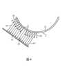
図2は、曲面アレイトランスデューサによって送信及び受信されるステアリングされていないビーム62によってスキャンされる画像フィールド60を示す。ビームの方向はアレイの湾曲形状によって決定されるため、ビームはステアリングされていない。各ビームは、アレイの正面に沿ったその原点に垂直に向けられている。ビーム形成において、ステアリングされていないビームは、原点の両側のアクティブ開口の対称的な位置で受信されたエコーに等しく重み付けすることによって形成される。ビームは、ビームフォーマ内で対称的な重み付けプロファイルを有する。同じ対称重み付けプロファイルを使用して、アレイに沿って各ビームを形成することができるが、アレイの幾何学的な湾曲によって、ビームの角度方向は異なる。したがって、アレイの自然な湾曲により、各ビーム62は、画像フィールドにわたって異なる角度に方向付けられ、したがって、セクタ形のフィールド60をスキャンする。これは、各異なるビーム方向に沿ったスキャン及びエコー形成のためにビームフォーマに1つの重み付けテーブルしかロードしなくてよいので、針挿入イメージングには有利である。広いセクタ画像フィールドは、針がプローブの片側からスキャン面に沿って体内に挿入されるため、針挿入イメージングに有利である。針は、数ミリメートル挿入した直後からセクタの片側においてビームと交差し始めるため、広い画像のエッジにおいて素早く収集される。2 shows an
しかし、ビーム角に対する挿入された針の角度が、針に衝突するビームの入射角に応じて、異なる送信ビームから検出されるエコーの程度が異なる。図2では、中央の暗い部分72の前後で針70と交差するビームは、針のシャフトに対して直交角度にない。これらのビームからのエコーは、ビーム経路から離れる方向に散乱し、アレイ素子に戻るそれらのエネルギーは少ない。ビーム64の両側の暗いビームは、針70のシャフトにより直交し、それらのエネルギーのより多くがアレイに直接反射して戻る。ビーム64は、その交差点において針に対してほぼ直交であり、このビームからのエコーは、鏡面反射針からアレイに最も強く戻るので最適である。したがって、図3の実際の超音波画像66に鮮明に示されているように、これらのより強いエコー戻りを生成する針部分72は、超音波画像に最もはっきりと現れる。(この画像は、分かり易くするために、白黒を反転させて表示している。)However, depending on the angle of the inserted needle relative to the beam angle, different degrees of echoes are detected from the different transmit beams, depending on the angle of incidence of the beams striking the needle. In FIG. 2, the beams that intersect the
本発明によれば、超音波システムは、針位置プロセッサ46を含む。針位置プロセッサ46は、超音波画像66内のはっきりと見える針部分72、具体的には、最適ビーム64の角度を特定する。針位置プロセッサは、画像処理を使用して、画像内の針部分72からの強いエコーの直線を探し、特定する。これは、ハフ変換、ラドン変換、1次及び2次方向性テクスチャ解析又は最大輝度解析といったヒューリスティック基準といった画像処理技術を使用して行うことができる。このエコー戻り部分が画像内に特定されると、最強エコー戻り部分に沿った点が、最適なステアリングされていないビームが針と交差する点を示し、したがって、ビームのアイデンティティが、単純なジオメトリによって決定される。ビーム64が針を最も強くイメージングするための最適角度を有するステアリングされていないビームとしてこのように特定されると、針位置プロセッサは、送信コントローラ18及びビームフォーマ20に命令して、アレイ12からステアリングされたビームを送受信させる。これらのビームはすべて、ビーム64の特定された最適角度でステアリングされる。このことは、アレイ12がビーム64’、…、64、…64’’を送信している図4に示される。これらのビームはすべて、針70に対してほぼ直交する角度である、針70に対して同じ角度で送受信される。比較のために、アレイ12からのステアリングされていないビームの角度を表す矢印62も示されている。ステアリングされたビーム64’、…、64、…64’’は、ステアリングされていないビームと同じアレイの正面Fに沿った点から生じているように見えるが、ビームをすべて平行に向け、直交角又はほぼ直交角で針に衝突させるアレイの正面Fに対する異なる各自の角度でのフェーズド操作によってステアリングされている。これらの平行にステアリングされたビームで針を撮像すると、針70から比較的強いエコーが戻り、超音波画像内により鮮明に且つはっきりと針が現れる。In accordance with the present invention, the ultrasound system includes a
曲面アレイから平行にステアリングされたビームでのスキャンは、曲面アレイの非自明の使用である。これは、曲面アレイには、その湾曲形状により、固有の優先的なラジアルスキャンパターンがあるからである。比較として、標準的なフラットリニアアレイには、固有のラジアルスキャンパターンはない。その平坦な形状により、リニアビームステアリング及びフェーズドビームステアリングのために選択されるアレイになっている。いわゆる「ステアリングされたリニア」スキャンは、フェーズドセクタスキャンのように、米国特許第5,014,710号(Maslak他)によって例示されるように、カラードップラーイメージングのためのフラットリニアアレイのフェーズド操作によって長い間行われてきている。超音波イメージングの当業者は、ステアリングされた平行ビームスキャンでの使用ではなく、その自然なラジアルスキャンパターンを利用するために、特に曲面アレイを選択するであろう。曲面アレイはこの動作モードには幾何学的に適していないだけでなく、曲面アレイからのビームのフェーズドステアリングは、以下で詳細に説明するように、急なビームステアリング角によってサイドローブアーティファクトクラッタをすぐに発生させる。Scanning with parallel steered beams from a curved array is a non-obvious use of the curved array because curved arrays have an inherent preferential radial scan pattern due to their curved geometry. In comparison, standard flat linear arrays have no inherent radial scan pattern. Their flat geometry makes them the array of choice for linear and phased beam steering. So-called "steered linear" scanning has long been performed by phased manipulation of flat linear arrays for color Doppler imaging, as exemplified by U.S. Pat. No. 5,014,710 (Maslak et al.), such as phased sector scanning. Those skilled in the art of ultrasound imaging would specifically choose a curved array to take advantage of its natural radial scan pattern, rather than for use in steered parallel beam scanning. Not only are curved arrays geometrically unsuited for this mode of operation, but phased steering of beams from a curved array quickly produces side lobe artifact clutter due to steep beam steering angles, as described in more detail below.
針位置プロセッサ46は、前述のとおりに動作して、説明したとおりに超音波画像内の針の位置を特定すると、グラフィックプロセッサ36に更に命令して、図5に示すように超音波画像66を針位置グラフィックでオーバーレイする。従来技術の針誘導システムは、概して、体内の針の位置に配置された点線のグラフィック80によって示すように、針の位置自体に針位置グラフィックを配置していた。これは、針の画像がグラフィックによって不明瞭になるため、困難をもたらす可能性がある。多くの場合、臨床医は、特に針先の周りに遮るものがない状態で針が画像内にあることを好む。臨床医は、通常、挿入を誘導するために針先に最も集中する。画像内の針を遮らない好適なグラフィックは、針の画像をその間に収めるグラフィックライン82a及び82bを有する。グラフィック82a、82bは、針又は針先の画像を不明瞭にすることなく、臨床医のために針の位置を素早く特定する。一部の臨床医は、両方のグラフィックス、つまり、針の位置を囲むライン82a、82bと、画像内の針のシャフトを明確に特定する明るい又は破線のグラフィック80との両方を使用することを好む場合がある。Once the
針の挿入が進むにつれ、臨床医が血管を貫通しないように又は体内の堅い物質を回避するために針を操作すると、挿入方向が変わる可能性がある。針の向きは、針の操作又はプローブの動きによって変化する可能性があるため、画像処理、最適ビーム角特定及びビームステアリングは、針位置プロセッサ46によって定期的に繰り返され、必要に応じてビーム64、64’のステアリング角を更新して、手順によって提供できる針の最も鮮明な画像が維持される。As needle insertion progresses, the insertion direction may change as the clinician manipulates the needle to avoid penetrating a blood vessel or to avoid hard material within the body. Because needle orientation may change due to needle manipulation or probe movement, image processing, optimal beam angle determination and beam steering are periodically repeated by
無線アンテナのような超音波アレイは、アレイによって送受信される超音波エネルギーのエネルギープロファイルを示す。超音波アレイのこのアンテナパターンは、ローブパターンと知られている。このパターンには、ビーム方向と軸方向に整列するメインローブ、即ち、中央ローブと、軸外エコーの受信に敏感なサイドローブとがある。ほとんどの場合、臨床医は、ビーム方向における強くて細いメインローブと、実質的に存在しないサイドローブとを好む。これは、画像フィールドにおけるサイドローブで受け取られるエネルギーは、ビーム形成中に、画像にアーチファクト、即ち、針の画像を不明瞭にする可能性があるクラッタを発生させるからである。ビームフォーマは、すべてのエネルギーがビーム軸に沿って受け取られることを前提にプログラムされている。サイドローブから受け取られる軸外エネルギーは、不所望のビームを形成し、結果として得られる画像にアーチファクトとして現れる。サイドローブクラッタアーチファクトは、素子ピッチ(中心間の間隔)が超音波周波数波長の半分未満であるプローブを使用することにより防止される。曲面アレイのビームがステアリングされていない場合、半波長素子ピッチによって、サイドローブクラッタの出現が回避される。しかし、ビームが、アレイ正面に対して増加する非直交角でステアリングされると、サイドローブが大きくなり、特に、アレイの湾曲によって、フラットリニアアレイの場合よりも急であるアレイの正面におけるステアリング角をもたらす曲面アレイの場合にサイドアーチファクトの可能性が増加する。図4では、最も外側の針イメージングビーム64’及び64’’は、アレイ12の正面Fに対して著しく非直交のステアリング角にあることが分かるが、これらのより急なステアリング角は、サイドローブ画像クラッタの原因となる可能性がある。本発明の更なる態様によれば、サイドローブクラッタは、超音波システム内のクラッタプロセッサ50によって低減される。クラッタプロセッサ50は、異なるアポダイゼーション関数をそれぞれ使用して、画像フィールドのスキャンから生成されるエコーから2つの超音波画像を形成する。2つの異なるアポダイズ画像のピクセル値を組み合わせて、最終画像のサイドローブクラッタアーチファクトが低減される。Ultrasound arrays, like radio antennas, exhibit an energy profile of the ultrasonic energy transmitted and received by the array. This antenna pattern of an ultrasound array is known as a lobe pattern. This pattern has a main lobe, or central lobe, that is axially aligned with the beam direction, and side lobes that are sensitive to receiving off-axis echoes. In most cases, clinicians prefer a strong, narrow main lobe in the beam direction and virtually non-existent side lobes. This is because energy received at the side lobes in the image field will generate artifacts in the image during beamforming, i.e. clutter that can obscure the image of the needle. The beamformer is programmed with the assumption that all energy is received along the beam axis. Off-axis energy received from the side lobes will form undesired beams and appear as artifacts in the resulting image. Side lobe clutter artifacts are prevented by using probes with element pitch (center-to-center spacing) less than half the ultrasound frequency wavelength. If the curved array is not beam-steered, a half-wave element pitch avoids the appearance of side lobe clutter. However, as the beams are steered at increasingly non-orthogonal angles relative to the front of the array, the side lobes become larger and the likelihood of side artifacts increases, especially for curved arrays where the curvature of the array results in steering angles at the front of the array that are steeper than for flat linear arrays. In FIG. 4, it can be seen that the outermost needle imaging beams 64' and 64'' are at significantly non-orthogonal steering angles relative to the front face F of the
図6に、クラッタ除去のためのアポディゼーション関数の1つのセットを示す。図6の下部には、方向yに延在するトランスデューサ素子eのアレイ12がある。アレイ12の上方に、2つの異なるアポダイゼーション関数92及び92を空間的に対応させて示す。1つのアポダイゼーション関数は、画像フィールドから受信したエコー信号をビーム形成して第1の画像を形成するときに使用され、もう1つのアポダイゼーション関数は、同じエコー信号をビーム形成して第2の画像を形成するときに使用される。アポディゼーション関数92は、2つの隣接する素子からの信号に重み1で重み付けし、次の2つの素子からの信号に重み0で重み付けし、そして、次の2つの信号に重み1で重み付けし、同様に続けられることがわかる。アポダイゼーション関数94は、開口にわたって重み1及び0を同じように交互にするが、逆である。2つの画像のビーム形成されたエコー信号は、振幅検出され、2つの画像のピクセル値が生成される。次に、2つの画像の同じ空間位置にあるピクセル値が比較又は相関される。2つの値の相関が高い(例えば50%を超える)場合、値の一方又は両方が、結果として得られる画像のピクセル値に使用される。2つの値の相関が比較的低い(例えば50%未満の)場合、値は画像から省略される。これは、2つの相補的なアポダイゼーション関数によって処理されるメインローブ信号がほぼ同じになるのに対し、2つの画像におけるメインローブの両側のサイドローブ(クラッタの最大の原因)からの信号は極性が逆で無相関だからである。したがって、サイドローブクラッタは、結果として得られる画像において低減される。この処理はすべて単一の画像収集で行われるため、表示のフレームレートに悪影響がない。また、このクラッタ低減処理は、振幅検出を使用するので、結果として得られるピクセル値は、Bモードプロセッサ52によってBモード画像に直ぐに処理することができる。6 shows one set of apodization functions for clutter rejection. At the bottom of FIG. 6 is an
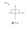
図7a及び図7bに、針画像のクラッタ低減のための好適なアポダイゼーション関数を示す。これら2つの図のグラフは、超音波トランスデューサアレイの中心からの距離yに対する電圧の重みvとしてプロットされている。図7aのグラフ410は、矩形アポダイゼーション関数の形の第1のアポダイゼーション関数の一例を示す。このアポダイゼーション関数により、トランスデューサアレイのすべての素子からの信号が、1といった等しい重みを受け取る。図8aに、この関数を受信エコーデータに適用した結果を示す。Figures 7a and 7b show suitable apodization functions for clutter reduction of needle images. The graphs in these two figures are plotted as voltage weight v versus distance y from the center of the ultrasound transducer array.
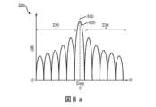
図8aは、ステアリング角θに対するdBで測定された振幅のプロット500を示す。このプロットは、アレイの視野内のすべてのステアリング角にわたるトランスデューサアレイの各トランスデューサ素子によって受信されたすべてのエコー信号の合計を示す。より具体的には、このプロットは、図7aに示す第1のアポダイゼーション関数410を使用してビーム形成された画像データ内のメインローブ及びサイドローブの応答を示す。これは、標準的なアポダイズされていないBモード超音波画像の応答特性であり、0°のステアリング角510において高強度応答、即ち、メインローブ応答520を有する。0°のステアリング角からの信号は、トランスデューサアレイにコヒーレントに到着し、均一なアポディゼーション関数410を使用して画像のメインローブ応答を形成する。空間分解能の制限により、メインローブ520は、0度の両側に小さい範囲の角度を含む有限の幅を有する。この特性を有する画像データはまた、メインローブから広がる減少する強度の複数の信号、即ち、サイドローブ530も含む。サイドローブは、メインローブの範囲外のステアリング角を有する信号の応答である。様々な角度での建設的干渉効果及び相殺的干渉効果により、サイドローブにピーク及びトラフが作成される。サイドローブは、超音波画像内にクラッタを引き起こす一方で、メインローブは、超音波画像標的からの所望の信号を提供する。8a shows a
図7bの第2のグラフ420は、図8bに示すように、画像データ応答にヌルポイントを導入するために使用される、y=1/xといった逆関数の形の第2のアポダイゼーション関数の一例を示す。このノッチフィルタがパスフィルタとしてローブ特性500に適用されると、アレイのビームパターンのメインローブからの信号は、高い重みを受け取り、これは、より横側のサイドローブからの信号に向かって指数関数的に減少する。図9に、この関数を受信エコーデータに適用した結果を示す。使用されるアポダイゼーション関数の形状は、超音波システムのユーザによってデザインされるか、システムに事前にロードされ、ユーザによって選択されて、所望の関数を行うようにされてもよい。アポダイゼーション関数の形状は、選択又はデザインされると、単一の制御パラメータを介して調整することができる。このパラメータは、超音波システムの使用を通じてユーザによって経験的に決定することができるスケーリング係数kである。The
線形音響学により、超音波ビームパターンは、使用されるアポダイゼーション関数のフーリエ変換と同等である。この関係は、解析及びビームパターンデザインのためのツールを提供する。より具体的には、所望のビームパターンを達成するように、アポディゼーション関数をデザインすることができる。例えば図8bに示すように、アポディゼーション関数420を使用することによって生成される画像データは、メインローブ位置における鋭いヌルと、軸外ステアリング角における減少した振幅とを示す。アポディゼーション関数420と第2の画像データのビームパターンとのフーリエ変換関係を使用して、所望のビームパターンを達成するために使用すべきアポダイゼーション関数のタイプを判別することができる。By linear acoustics, the ultrasound beam pattern is equivalent to the Fourier transform of the apodization function used. This relationship provides a tool for analysis and beam pattern design. More specifically, the apodization function can be designed to achieve a desired beam pattern. For example, as shown in FIG. 8b, the image data generated by using the
逆数の第2のアポディゼーション関数420をエコー信号データに適用することにより、アポディゼーション関数410を使用して処理された画像データのメインローブ520と同じステアリング角においてヌル560が生成される。この例では、第2のアポダイゼーション関数420は、ノッチフィルタとして機能しているが、用途に応じて、多くの異なる形状のアポダイゼーション関数を利用することができる。Applying the inverse
図9は、画像ピクセルについて第1のアポダイゼーション関数410及び第2のアポダイゼーション関数420を使用することにより得られる画像データを示す図8a及び図8bからのプロットの重ね合わせを示すプロット600を示す。アポディゼーション関数によって処理された第1の画像及び第2の画像のピクセルを比較することにより、ステアリング角全体での最小の信号振幅が分かる。これは、サイドローブ応答の破線630によって強調表示される。所望のメインローブ610の信号は、第2のアポダイゼーション関数620の特性であるノッチに入る。このようにして、サイドローブ630のクラッタ信号が選択され、メインローブ610の信号から分離される。次に、サイドローブ応答630からの不所望の値が、図8aに示す応答を有する第1のアポダイゼーション関数410を使用して得られた画像データから差し引かれる。結果として、メインローブ応答520から主に返された信号が得られ、ローブパターンのサイドローブ530の信号は実質的に除去され、つまり、画像形成に使用される結果として得られる信号は、主にローブ特性のメインローブ応答からの信号である。このようにして、サイドローブクラッタは超音波画像から実質的に除去される。9 shows a
図7bのグラフ420に示す第2のアポディゼーション関数の形状は、第2の画像データにおけるヌル関数560の幅を変更するために変えることができる。このようにすると、残りの信号の角度の広がりを制御することができる。このノッチ関数の幅を小さくすることにより、最終的な超音波画像の空間分解能を高めることができる。The shape of the second apodization function shown in
図10に、本発明による超音波画像誘導針挿入の手順を概説する。臨床医は、曲面アレイトランスデューサプローブを被験者の体に配置し、手順の標的解剖学的構造が視野に入るまでプローブを操作することによって手順を開始する。標的解剖学的構造は、例えば針を使用して生検を行う嚢胞である。標的解剖学的構造が超音波画像内にある状態で、ステップ102に示すように、臨床医は、画像の平面に沿って針を挿入し始める。ステップ104に示すように、挿入が進むにつれて、曲面アレイトランスデューサは、ステアリングされていないビームを視野全体に送信して、視野を画像化し、針の挿入を捕捉する。ステップ106において、超音波システムの針位置プロセッサが、画像内に、曲面アレイから放射状に向けられたビームが最も好適な角度の周辺で針と交差する針の鏡面反射ラインを特定する。ステップ108において、針位置プロセッサは、針反射ラインに沿った最も明るい点を特定する。これにより、ステップ110に示すように、当該明るい点を生成した送信ビームの角度が特定される。次に、ステップ112に示すように、針位置プロセッサは、送信コントローラに、特定されたビーム角において、針に向けて平行なステアリングされたビームを送信するように曲面アレイトランスデューサを制御させる。平行なステアリングされたビームを用いてスキャンすると、針の最も強い画像が生成され、ステップ114において、画像と共に針誘導グラフィックが、好適には、超音波画像内の針の位置の両側に表示される。次に、前述したように、2重アポダイゼーション処理手法の1つを使用して、クラッタを低減することができる。FIG. 10 outlines the procedure for ultrasound image-guided needle insertion according to the present invention. The clinician begins the procedure by placing a curved array transducer probe on the subject's body and manipulating the probe until the target anatomical structure of the procedure is in view. The target anatomical structure is, for example, a cyst to be biopsied using the needle. With the target anatomical structure in the ultrasound image, the clinician begins to insert the needle along the plane of the image, as shown in
なお、本発明の実施態様における使用に適した超音波システム、特に図1の超音波システムのコンポーネント構造は、ハードウェア、ソフトウェア又はこれらの組み合わせで実施することができる。超音波システムの様々な実施形態及び/又はコンポーネント、例えば針位置プロセッサ46及びクラッタプロセッサ50又はその中のコンポーネント及びコントローラも、1つ以上のコンピュータ又はマイクロプロセッサの一部として実施することができる。コンピュータ又はプロセッサは、コンピューティングデバイス、入力デバイス、表示ユニット及び例えばインターネットにアクセスするためのインターフェースを含む。コンピュータ又はプロセッサは、マイクロプロセッサを含む。マイクロプロセッサは、例えばPACSシステム又はトレーニング画像をインポートするためのデータネットワークにアクセスするための通信バスに接続される。コンピュータ又はプロセッサはまた、メモリを含む。3D画像データメモリ48といったメモリデバイスは、ランダムアクセスメモリ(RAM)及び読み取り専用メモリ(ROM)を含む。コンピュータ又はプロセッサは更に、ハードディスクドライブ、又は、フロッピー(登録商標)ディスクドライブ、光学ディスクドライブ、ソリッドステートサムドライブ等といったリムーバブルストレージドライブであってよいストレージデバイスを含む。ストレージデバイスはまた、コンピュータ又はプロセッサにコンピュータプログラム又は他の命令をロードするための他の同様の手段であってもよい。It should be noted that the ultrasound system suitable for use in the implementation of the present invention, and in particular the component structure of the ultrasound system of FIG. 1, may be implemented in hardware, software, or a combination thereof. Various embodiments and/or components of the ultrasound system, such as the
本明細書において使用する場合、「コンピュータ」、「モジュール」、「プロセッサ」又は「ワークステーション」との用語には、マイクロコントローラ、縮小命令セットコンピュータ(RISC)、ASIC、論理回路及び本明細書に説明される機能を実行可能な任意の他の回路又はプロセッサを使用するシステムを含む任意のプロセッサベース又はマイクロプロセッサベースのシステムを含んでよい。上記例は単なる例示であり、したがって、これらの用語の定義及び/又は意味を決して限定するものではない。As used herein, the terms "computer," "module," "processor," or "workstation" may include any processor-based or microprocessor-based system, including systems using microcontrollers, reduced instruction set computers (RISC), ASICs, logic circuits, and any other circuits or processors capable of performing the functions described herein. The above examples are merely illustrative and thus do not limit in any way the definition and/or meaning of these terms.
コンピュータ又はプロセッサは、入力データを処理するために、1つ以上のストレージ要素に格納されている命令セットを実行する。ストレージ要素はまた、所望通りに又は必要に応じてデータ又は他の情報を格納することもできる。ストレージ要素は、情報源又は処理マシン内の物理メモリ要素の形であってもよい。The computer or processor executes a set of instructions stored in one or more storage elements to process input data. The storage elements may also store data or other information as desired or needed. The storage elements may be in the form of information sources or physical memory elements within the processing machine.
上述したような超音波画像の収集、処理及び送信を制御する命令を含む超音波システムの命令のセットは、本発明の様々な実施形態の方法及びプロセスといった特定の動作を行うように、処理マシンとしてのコンピュータ又はプロセッサに命令する様々なコマンドを含んでよい。命令のセットは、ソフトウェアプログラムの形式であってよい。ソフトウェアは、システムソフトウェア又はアプリケーションソフトウェアといった様々な形であってよく、また、有形及び非一時的なコンピュータ可読媒体として具現化されてよい。更に、ソフトウェアは、別個のプログラム又は針位置モジュール、クラッタモジュールといったモジュールの集合、より大きなプログラム内のプログラムモジュール又はプログラムモジュールの一部の形であってもよい。ソフトウェアはまた、オブジェクト指向プログラミングの形のモジュラープログラミングを含んでもよい。処理マシンによる入力データの処理は、オペレータのコマンドに応答するものであっても、前の処理の結果に応答するものであっても、別の処理マシンによる要求に応答するものであってもよい。The set of instructions for the ultrasound system, including instructions for controlling the acquisition, processing and transmission of ultrasound images as described above, may include various commands that instruct a computer or processor as a processing machine to perform certain operations, such as the methods and processes of various embodiments of the present invention. The set of instructions may be in the form of a software program. The software may be in various forms, such as system software or application software, and may be embodied as a tangible and non-transitory computer readable medium. Furthermore, the software may be in the form of a separate program or collection of modules, such as a needle location module, a clutter module, a program module within a larger program, or a portion of a program module. The software may also include modular programming in the form of object-oriented programming. The processing of input data by the processing machine may be in response to an operator's commands, in response to results of previous processing, or in response to a request by another processing machine.
更に、以下の請求項の限定は、ミーンズプラスファンクション形式で書かれておらず、当該請求項の限定が更なる構造のない機能の記述が続く「means for」との語句を明示的に使用していない限り、米国特許法第112条第6段落に基づいて解釈されることを意図していない。Furthermore, the following claim limitations are not written in means-plus-function form and are not intended to be construed under 35 U.S.C. 35 U.S.C. 112, sixth paragraph, unless such claim limitations expressly use the phrase "means for" followed by a description of a function without further structure.
Claims (5)
Translated fromJapanese曲面アレイトランスデューサを含むプローブであって、前記曲面アレイトランスデューサは、前記被験者内の画像フィールド全体に、ステアリングされていないビームを送信し、これにより前記ステアリングされていないビームを使用して前記画像フィールドの超音波画像を得る、プローブと、
前記超音波画像への画像処理の適用に基づいて、前記画像フィールド内の針から最大振幅のエコー戻りを生成する送信ビームのピーク角を特定する針位置プロセッサと、を有し、
前記針位置プロセッサは更に、前記曲面アレイトランスデューサを制御して前記ピーク角で複数の平行のステアリングされたビームを送信し、
前記針位置プロセッサは更に、前記超音波画像内の針鏡面反射ラインを特定し、
前記針位置プロセッサは更に、前記針鏡面反射ラインに沿って最も明るい点を特定し、
前記送信ビームの前記ピーク角を特定することは、前記最も明るい点において、前記針鏡面反射ラインと交差する前記送信ビームを特定することを含み、
特定された前記送信ビームは、前記ピーク角を示す、
超音波イメージングシステム。 1. An ultrasound imagingsystemfor image guidance of needle insertion into a subject,the ultrasound imaging system comprising:
a probe including a curved array transducer thattransmits unsteered beams across an image field within the subject, thereby obtaining an ultrasound image of the image field using the unsteered beams;
a needle position processor that identifies a peak angle of a transmit beam that produces a maximum amplitude echo return from the needle within the image fieldbased on application of image processing to the ultrasound image ;
The needle position processor further controls the curved array transducer to transmit a plurality of parallel steered beams at the peak angle;
The needle location processor further identifies a needle specular reflection line within the ultrasound image;
The needle position processor further identifies the brightest point along the needle specular reflection line;
Identifying the peak angle of the transmit beam includes identifying the transmit beam that intersects the needle specular reflection line at the brightest point;
The identified transmit beam exhibits the peak angle.
Ultrasound imaging systems .
前記画像ディスプレイは更に、前記画像フィールド内の前記針の更なる超音波画像を表示し、前記更なる超音波画像は、前記ステアリングされたビームに基づいて得られ、
前記画像ディスプレイは更に、前記超音波画像内に、針誘導グラフィックを表示する、請求項1に記載の超音波イメージングシステム。the ultrasound imaging system further comprising an image display;
the image display further displays a further ultrasound image of the needle within the image field, the further ultrasound image being obtained based on the steered beam;
The ultrasound imaging system of claim 1 ,wherein the image display furtherdisplays a needle guidance graphic within the ultrasound image.
Applications Claiming Priority (4)
| Application Number | Priority Date | Filing Date | Title |
|---|---|---|---|
| US201862620512P | 2018-01-23 | 2018-01-23 | |
| US62/620,512 | 2018-01-23 | ||
| JP2020560552AJP7401459B2 (en) | 2018-01-23 | 2019-01-15 | Ultrasound imaging system providing needle insertion guidance |
| PCT/EP2019/050844WO2019145183A1 (en) | 2018-01-23 | 2019-01-15 | Ultrasound imaging system providing needle insertion guidance |
Related Parent Applications (1)
| Application Number | Title | Priority Date | Filing Date |
|---|---|---|---|
| JP2020560552ADivisionJP7401459B2 (en) | 2018-01-23 | 2019-01-15 | Ultrasound imaging system providing needle insertion guidance |
Publications (2)
| Publication Number | Publication Date |
|---|---|
| JP2024026301A JP2024026301A (en) | 2024-02-28 |
| JP7592835B2true JP7592835B2 (en) | 2024-12-02 |
Family
ID=65036779
Family Applications (3)
| Application Number | Title | Priority Date | Filing Date |
|---|---|---|---|
| JP2020560552AActiveJP7401459B2 (en) | 2018-01-23 | 2019-01-15 | Ultrasound imaging system providing needle insertion guidance |
| JP2023083092AActiveJP7550919B2 (en) | 2018-01-23 | 2023-05-19 | Ultrasound imaging system to provide needle insertion guidance |
| JP2023206609AActiveJP7592835B2 (en) | 2018-01-23 | 2023-12-07 | Ultrasound imaging system to provide needle insertion guidance |
Family Applications Before (2)
| Application Number | Title | Priority Date | Filing Date |
|---|---|---|---|
| JP2020560552AActiveJP7401459B2 (en) | 2018-01-23 | 2019-01-15 | Ultrasound imaging system providing needle insertion guidance |
| JP2023083092AActiveJP7550919B2 (en) | 2018-01-23 | 2023-05-19 | Ultrasound imaging system to provide needle insertion guidance |
Country Status (5)
| Country | Link |
|---|---|
| US (2) | US11918300B2 (en) |
| EP (1) | EP3742981B1 (en) |
| JP (3) | JP7401459B2 (en) |
| CN (2) | CN119014903A (en) |
| WO (1) | WO2019145183A1 (en) |
Families Citing this family (1)
| Publication number | Priority date | Publication date | Assignee | Title |
|---|---|---|---|---|
| CN117321444A (en)* | 2021-04-26 | 2023-12-29 | 飞利浦影像引导治疗公司 | Filtering and apodization combination for ultrasound image generation and associated systems, methods, and devices |
Citations (6)
| Publication number | Priority date | Publication date | Assignee | Title |
|---|---|---|---|---|
| JP2003126093A (en) | 2001-10-23 | 2003-05-07 | Olympus Optical Co Ltd | Ultrasonic diagnostic apparatus |
| JP2004208859A (en) | 2002-12-27 | 2004-07-29 | Toshiba Corp | Ultrasound diagnostic equipment |
| JP2013223639A (en) | 2012-04-23 | 2013-10-31 | Fujifilm Corp | Ultrasound diagnostic apparatus and ultrasound image display method |
| US20140155738A1 (en) | 2012-11-30 | 2014-06-05 | General Electric Company | Apparatus and method for ultrasound imaging |
| JP2014100556A (en) | 2012-10-23 | 2014-06-05 | Toshiba Corp | Ultrasonic diagnostic apparatus and ultrasonic diagnostic apparatus control method |
| JP2014138847A (en) | 2013-01-03 | 2014-07-31 | Siemenscorp | Needle enhancement in diagnostic ultrasound imaging |
Family Cites Families (27)
| Publication number | Priority date | Publication date | Assignee | Title |
|---|---|---|---|---|
| US5014710A (en) | 1988-09-13 | 1991-05-14 | Acuson Corporation | Steered linear color doppler imaging |
| US5105814A (en)* | 1990-08-15 | 1992-04-21 | Hewlett-Packard Company | Method of transforming a multi-beam ultrasonic image |
| US5235982A (en)* | 1991-09-30 | 1993-08-17 | General Electric Company | Dynamic transmit focusing of a steered ultrasonic beam |
| US5833613A (en) | 1996-09-27 | 1998-11-10 | Advanced Technology Laboratories, Inc. | Ultrasonic diagnostic imaging with contrast agents |
| US6193659B1 (en)* | 1997-07-15 | 2001-02-27 | Acuson Corporation | Medical ultrasonic diagnostic imaging method and apparatus |
| US20020173721A1 (en)* | 1999-08-20 | 2002-11-21 | Novasonics, Inc. | User interface for handheld imaging devices |
| US6436044B1 (en)* | 2000-02-14 | 2002-08-20 | Siemens Medical Solutions Usa, Inc. | System and method for adaptive beamformer apodization |
| US6530885B1 (en) | 2000-03-17 | 2003-03-11 | Atl Ultrasound, Inc. | Spatially compounded three dimensional ultrasonic images |
| US6443896B1 (en) | 2000-08-17 | 2002-09-03 | Koninklijke Philips Electronics N.V. | Method for creating multiplanar ultrasonic images of a three dimensional object |
| US6524247B2 (en) | 2001-05-15 | 2003-02-25 | U-Systems, Inc. | Method and system for ultrasound imaging of a biopsy needle |
| US6951542B2 (en) | 2002-06-26 | 2005-10-04 | Esaote S.P.A. | Method and apparatus for ultrasound imaging of a biopsy needle or the like during an ultrasound imaging examination |
| EP1815796A4 (en)* | 2004-11-17 | 2009-10-28 | Hitachi Medical Corp | ULTRASONIC UNIT AND METHOD FOR DISPLAYING AN ULTRASOUND IMAGE |
| US8254654B2 (en)* | 2007-10-31 | 2012-08-28 | University Of Southern California | Sidelobe suppression in ultrasound imaging using dual apodization with cross-correlation |
| WO2011057252A1 (en)* | 2009-11-09 | 2011-05-12 | Sonosite, Inc. | Systems and methods for beam enhancement |
| US20130258805A1 (en)* | 2010-10-11 | 2013-10-03 | B-K Medical Aps | Methods and systems for producing compounded ultrasound images |
| JP5961623B2 (en)* | 2010-11-19 | 2016-08-02 | コーニンクレッカ フィリップス エヌ ヴェKoninklijke Philips N.V. | Method for guiding the insertion of surgical instruments using three-dimensional ultrasound imaging |
| JP5435751B2 (en)* | 2011-03-03 | 2014-03-05 | 富士フイルム株式会社 | Ultrasonic diagnostic apparatus, ultrasonic transmission / reception method, and ultrasonic transmission / reception program |
| WO2015029499A1 (en)* | 2013-08-30 | 2015-03-05 | 富士フイルム株式会社 | Ultrasonic diagnostic device and ultrasonic image generation method |
| US9622724B2 (en)* | 2014-03-31 | 2017-04-18 | General Electric Company | Ultrasound imaging system and method for tracking a specular reflector |
| EP3126872B1 (en)* | 2014-03-31 | 2021-05-12 | Koninklijke Philips N.V. | System and method for acoustic imaging with coherent compounding using intercostal spaces |
| JP6309340B2 (en)* | 2014-05-08 | 2018-04-11 | キヤノンメディカルシステムズ株式会社 | Ultrasonic diagnostic apparatus and ultrasonic imaging program |
| US10624612B2 (en)* | 2014-06-05 | 2020-04-21 | Chikayoshi Sumi | Beamforming method, measurement and imaging instruments, and communication instruments |
| US11020143B2 (en)* | 2015-07-20 | 2021-06-01 | Edan Instruments, Inc. | Adaptive steering adjustment for needle visualization |
| US10292678B2 (en)* | 2015-09-23 | 2019-05-21 | Analogic Corporation | Real-time image based risk assessment for an instrument along a path to a target in an object |
| US10281568B2 (en)* | 2015-10-16 | 2019-05-07 | The Board Of Trustees Of The University Of Illinois | Method and apparatus for null subtraction ultrasound imaging |
| KR20170060852A (en)* | 2015-11-25 | 2017-06-02 | 삼성메디슨 주식회사 | Method and ultrasound apparatus for providing ultrasound images |
| JP6668817B2 (en)* | 2016-02-26 | 2020-03-18 | コニカミノルタ株式会社 | Ultrasound diagnostic apparatus and control program |
- 2019
- 2019-01-15EPEP19700888.1Apatent/EP3742981B1/enactiveActive
- 2019-01-15JPJP2020560552Apatent/JP7401459B2/enactiveActive
- 2019-01-15USUS16/963,859patent/US11918300B2/enactiveActive
- 2019-01-15CNCN202411098051.2Apatent/CN119014903A/enactivePending
- 2019-01-15WOPCT/EP2019/050844patent/WO2019145183A1/ennot_activeCeased
- 2019-01-15CNCN201980009884.8Apatent/CN111629672B/enactiveActive
- 2023
- 2023-05-19JPJP2023083092Apatent/JP7550919B2/enactiveActive
- 2023-12-07JPJP2023206609Apatent/JP7592835B2/enactiveActive
- 2024
- 2024-01-30USUS18/426,712patent/US20240164847A1/enactivePending
Patent Citations (6)
| Publication number | Priority date | Publication date | Assignee | Title |
|---|---|---|---|---|
| JP2003126093A (en) | 2001-10-23 | 2003-05-07 | Olympus Optical Co Ltd | Ultrasonic diagnostic apparatus |
| JP2004208859A (en) | 2002-12-27 | 2004-07-29 | Toshiba Corp | Ultrasound diagnostic equipment |
| JP2013223639A (en) | 2012-04-23 | 2013-10-31 | Fujifilm Corp | Ultrasound diagnostic apparatus and ultrasound image display method |
| JP2014100556A (en) | 2012-10-23 | 2014-06-05 | Toshiba Corp | Ultrasonic diagnostic apparatus and ultrasonic diagnostic apparatus control method |
| US20140155738A1 (en) | 2012-11-30 | 2014-06-05 | General Electric Company | Apparatus and method for ultrasound imaging |
| JP2014138847A (en) | 2013-01-03 | 2014-07-31 | Siemenscorp | Needle enhancement in diagnostic ultrasound imaging |
Also Published As
| Publication number | Publication date |
|---|---|
| JP7550919B2 (en) | 2024-09-13 |
| CN111629672B (en) | 2024-08-23 |
| JP2023106510A (en) | 2023-08-01 |
| CN119014903A (en) | 2024-11-26 |
| JP7401459B2 (en) | 2023-12-19 |
| EP3742981B1 (en) | 2024-03-13 |
| WO2019145183A1 (en) | 2019-08-01 |
| US20210038320A1 (en) | 2021-02-11 |
| US20240164847A1 (en) | 2024-05-23 |
| EP3742981A1 (en) | 2020-12-02 |
| JP2024026301A (en) | 2024-02-28 |
| CN111629672A (en) | 2020-09-04 |
| US11918300B2 (en) | 2024-03-05 |
| JP2021510618A (en) | 2021-04-30 |
Similar Documents
| Publication | Publication Date | Title |
|---|---|---|
| EP3797702B1 (en) | Multi-frequency mapping catheter and method of mapping | |
| US9597054B2 (en) | Ultrasonic guidance of a needle path during biopsy | |
| KR102396008B1 (en) | Ultrasound imaging system and method for tracking a specular reflector | |
| JP6342212B2 (en) | Ultrasonic diagnostic equipment | |
| JP7449278B2 (en) | 3D ultrasound imaging with wide focused transmit beam at high display frame rate | |
| US9204862B2 (en) | Method and apparatus for performing ultrasound elevation compounding | |
| EP3512432B1 (en) | An apparatus and method for detecting an interventional tool | |
| CN107997783B (en) | Self-adaptive ultrasonic beam synthesis method and system based on ultrasonic directionality | |
| JP7592835B2 (en) | Ultrasound imaging system to provide needle insertion guidance | |
| US11607194B2 (en) | Ultrasound imaging system with depth-dependent transmit focus | |
| CN110431443A (en) | Method and system for being filtered to ultrasound image clutter | |
| US8394027B2 (en) | Multi-plane/multi-slice processing for 2-D flow imaging in medical diagnostic ultrasound | |
| CN110636799B (en) | Optimal scan plane selection for organ viewing | |
| JP4917259B2 (en) | Method and system for angle-dependent backscatter space synthesis | |
| WO2018050885A1 (en) | An apparatus and method for detecting an interventional tool |
Legal Events
| Date | Code | Title | Description |
|---|---|---|---|
| A521 | Request for written amendment filed | Free format text:JAPANESE INTERMEDIATE CODE: A523 Effective date:20231220 | |
| A621 | Written request for application examination | Free format text:JAPANESE INTERMEDIATE CODE: A621 Effective date:20231220 | |
| A977 | Report on retrieval | Free format text:JAPANESE INTERMEDIATE CODE: A971007 Effective date:20241016 | |
| TRDD | Decision of grant or rejection written | ||
| A01 | Written decision to grant a patent or to grant a registration (utility model) | Free format text:JAPANESE INTERMEDIATE CODE: A01 Effective date:20241022 | |
| A61 | First payment of annual fees (during grant procedure) | Free format text:JAPANESE INTERMEDIATE CODE: A61 Effective date:20241120 | |
| R150 | Certificate of patent or registration of utility model | Ref document number:7592835 Country of ref document:JP Free format text:JAPANESE INTERMEDIATE CODE: R150 |