JP7592063B2 - Information processing system and information processing method - Google Patents
Information processing system and information processing methodDownload PDFInfo
- Publication number
- JP7592063B2 JP7592063B2JP2022212311AJP2022212311AJP7592063B2JP 7592063 B2JP7592063 B2JP 7592063B2JP 2022212311 AJP2022212311 AJP 2022212311AJP 2022212311 AJP2022212311 AJP 2022212311AJP 7592063 B2JP7592063 B2JP 7592063B2
- Authority
- JP
- Japan
- Prior art keywords
- storage
- data
- storage controller
- server
- controller
- Prior art date
- Legal status (The legal status is an assumption and is not a legal conclusion. Google has not performed a legal analysis and makes no representation as to the accuracy of the status listed.)
- Active
Links
Images


Classifications
- G—PHYSICS
- G06—COMPUTING OR CALCULATING; COUNTING
- G06F—ELECTRIC DIGITAL DATA PROCESSING
- G06F13/00—Interconnection of, or transfer of information or other signals between, memories, input/output devices or central processing units
- G06F13/14—Handling requests for interconnection or transfer
- G06F13/16—Handling requests for interconnection or transfer for access to memory bus
- G06F13/1668—Details of memory controller
- G—PHYSICS
- G06—COMPUTING OR CALCULATING; COUNTING
- G06F—ELECTRIC DIGITAL DATA PROCESSING
- G06F11/00—Error detection; Error correction; Monitoring
- G06F11/07—Responding to the occurrence of a fault, e.g. fault tolerance
- G06F11/16—Error detection or correction of the data by redundancy in hardware
- G06F11/20—Error detection or correction of the data by redundancy in hardware using active fault-masking, e.g. by switching out faulty elements or by switching in spare elements
- G06F11/2053—Error detection or correction of the data by redundancy in hardware using active fault-masking, e.g. by switching out faulty elements or by switching in spare elements where persistent mass storage functionality or persistent mass storage control functionality is redundant
- G06F11/2089—Redundant storage control functionality
- G06F11/2092—Techniques of failing over between control units
- G—PHYSICS
- G06—COMPUTING OR CALCULATING; COUNTING
- G06F—ELECTRIC DIGITAL DATA PROCESSING
- G06F11/00—Error detection; Error correction; Monitoring
- G06F11/07—Responding to the occurrence of a fault, e.g. fault tolerance
- G06F11/16—Error detection or correction of the data by redundancy in hardware
- G06F11/20—Error detection or correction of the data by redundancy in hardware using active fault-masking, e.g. by switching out faulty elements or by switching in spare elements
- G06F11/2053—Error detection or correction of the data by redundancy in hardware using active fault-masking, e.g. by switching out faulty elements or by switching in spare elements where persistent mass storage functionality or persistent mass storage control functionality is redundant
- G06F11/2056—Error detection or correction of the data by redundancy in hardware using active fault-masking, e.g. by switching out faulty elements or by switching in spare elements where persistent mass storage functionality or persistent mass storage control functionality is redundant by mirroring
- G06F11/2069—Management of state, configuration or failover
- G—PHYSICS
- G06—COMPUTING OR CALCULATING; COUNTING
- G06F—ELECTRIC DIGITAL DATA PROCESSING
- G06F11/00—Error detection; Error correction; Monitoring
- G06F11/07—Responding to the occurrence of a fault, e.g. fault tolerance
- G06F11/14—Error detection or correction of the data by redundancy in operation
- G06F11/1402—Saving, restoring, recovering or retrying
- G06F11/1446—Point-in-time backing up or restoration of persistent data
- G—PHYSICS
- G06—COMPUTING OR CALCULATING; COUNTING
- G06F—ELECTRIC DIGITAL DATA PROCESSING
- G06F11/00—Error detection; Error correction; Monitoring
- G06F11/07—Responding to the occurrence of a fault, e.g. fault tolerance
- G06F11/16—Error detection or correction of the data by redundancy in hardware
- G06F11/1658—Data re-synchronization of a redundant component, or initial sync of replacement, additional or spare unit
- G06F11/1662—Data re-synchronization of a redundant component, or initial sync of replacement, additional or spare unit the resynchronized component or unit being a persistent storage device
- G—PHYSICS
- G06—COMPUTING OR CALCULATING; COUNTING
- G06F—ELECTRIC DIGITAL DATA PROCESSING
- G06F11/00—Error detection; Error correction; Monitoring
- G06F11/07—Responding to the occurrence of a fault, e.g. fault tolerance
- G06F11/16—Error detection or correction of the data by redundancy in hardware
- G06F11/20—Error detection or correction of the data by redundancy in hardware using active fault-masking, e.g. by switching out faulty elements or by switching in spare elements
- G06F11/202—Error detection or correction of the data by redundancy in hardware using active fault-masking, e.g. by switching out faulty elements or by switching in spare elements where processing functionality is redundant
- G06F11/2023—Failover techniques
- G06F11/203—Failover techniques using migration
- G—PHYSICS
- G06—COMPUTING OR CALCULATING; COUNTING
- G06F—ELECTRIC DIGITAL DATA PROCESSING
- G06F11/00—Error detection; Error correction; Monitoring
- G06F11/07—Responding to the occurrence of a fault, e.g. fault tolerance
- G06F11/16—Error detection or correction of the data by redundancy in hardware
- G06F11/20—Error detection or correction of the data by redundancy in hardware using active fault-masking, e.g. by switching out faulty elements or by switching in spare elements
- G06F11/2053—Error detection or correction of the data by redundancy in hardware using active fault-masking, e.g. by switching out faulty elements or by switching in spare elements where persistent mass storage functionality or persistent mass storage control functionality is redundant
- G06F11/2056—Error detection or correction of the data by redundancy in hardware using active fault-masking, e.g. by switching out faulty elements or by switching in spare elements where persistent mass storage functionality or persistent mass storage control functionality is redundant by mirroring
- G06F11/2087—Error detection or correction of the data by redundancy in hardware using active fault-masking, e.g. by switching out faulty elements or by switching in spare elements where persistent mass storage functionality or persistent mass storage control functionality is redundant by mirroring with a common controller
- G—PHYSICS
- G06—COMPUTING OR CALCULATING; COUNTING
- G06F—ELECTRIC DIGITAL DATA PROCESSING
- G06F11/00—Error detection; Error correction; Monitoring
- G06F11/07—Responding to the occurrence of a fault, e.g. fault tolerance
- G06F11/16—Error detection or correction of the data by redundancy in hardware
- G06F11/20—Error detection or correction of the data by redundancy in hardware using active fault-masking, e.g. by switching out faulty elements or by switching in spare elements
- G06F11/2053—Error detection or correction of the data by redundancy in hardware using active fault-masking, e.g. by switching out faulty elements or by switching in spare elements where persistent mass storage functionality or persistent mass storage control functionality is redundant
- G06F11/2089—Redundant storage control functionality
- G—PHYSICS
- G06—COMPUTING OR CALCULATING; COUNTING
- G06F—ELECTRIC DIGITAL DATA PROCESSING
- G06F11/00—Error detection; Error correction; Monitoring
- G06F11/07—Responding to the occurrence of a fault, e.g. fault tolerance
- G06F11/16—Error detection or correction of the data by redundancy in hardware
- G06F11/20—Error detection or correction of the data by redundancy in hardware using active fault-masking, e.g. by switching out faulty elements or by switching in spare elements
- G06F11/2053—Error detection or correction of the data by redundancy in hardware using active fault-masking, e.g. by switching out faulty elements or by switching in spare elements where persistent mass storage functionality or persistent mass storage control functionality is redundant
- G06F11/2094—Redundant storage or storage space
Landscapes
- Engineering & Computer Science (AREA)
- Theoretical Computer Science (AREA)
- Physics & Mathematics (AREA)
- General Engineering & Computer Science (AREA)
- General Physics & Mathematics (AREA)
- Quality & Reliability (AREA)
- Information Retrieval, Db Structures And Fs Structures Therefor (AREA)
Description
Translated fromJapanese本発明は情報処理システム及び情報処理方法に関し、例えば、分散ストレージシステムに適用して好適なものである。The present invention relates to an information processing system and an information processing method, and is suitable for application to, for example, a distributed storage system.
近年、クラウドの利用拡大に伴い、クラウド上のデータを管理するストレージのニーズが高まっている。特に、クラウドは複数の拠点(以下、適宜、これをアベイラビリティゾーンと呼ぶ)で構成されており、アベイラビリティゾーン単位での障害に耐え得る高可用なストレージシステムが求められている。In recent years, with the expansion of cloud usage, there has been a growing need for storage to manage data on the cloud. In particular, clouds are made up of multiple locations (hereinafter referred to as availability zones), and there is a demand for highly available storage systems that can withstand failures on an availability zone basis.
なお、ストレージシステムを高可用化する技術として、例えば、特許文献1には、データセンタ内/データセンタ間で階層的にデータを冗長化する技術が開示されている。また特許文献2には、ユーザデータの格納先とは異なる1つ以上のストレージノードにデータ復元用の符号(パリティ)を格納する技術が開示されている。As a technique for increasing the availability of storage systems, for example,
ところで、通常、クラウドの各アベイラビリティゾーンは地理的に離れており、アベイラビリティゾーンを跨いで分散ストレージシステムを構成すると、アベイラビリティゾーン間の通信が発生し、その通信遅延によりI/O性能に影響を与えるという問題があった。またアベイラビリティゾーン間は通信量に応じて課金が発生するため、通信量が多いと高コストになるという問題もあった。However, cloud availability zones are usually geographically separated, and configuring a distributed storage system across availability zones creates the problem of communication between the availability zones, which can affect I/O performance due to communication delays. In addition, charges are incurred between availability zones according to the amount of communication, which can lead to high costs if the amount of communication is large.
本発明は以上の点を考慮してなされたもので、本発明の主たる目的は、拠点(アベイラビリティゾーン)単位での障害に耐え得る高可用な情報処理システム及び情報処理方法を提案することであり、本発明の他の目的は、さらに拠点間の通信に伴う通信遅延を原因とするI/O性能の低下や、拠点間の通信に起因するコストの発生を抑制し得る情報処理システム及び情報処理方法を提案することである。The present invention has been made in consideration of the above points, and the main object of the present invention is to propose a highly available information processing system and information processing method that can withstand failures at the base (availability zone) level, and another object of the present invention is to propose an information processing system and information processing method that can further suppress degradation of I/O performance caused by communication delays associated with communication between bases, and the occurrence of costs due to communication between bases.
かかる課題を解決するため本発明においては、ネットワークで接続された複数の拠点にそれぞれ複数配置されたストレージサーバを有する情報処理システムにおいて、前記拠点にそれぞれ配置され、データを記憶する記憶装置と、前記ストレージサーバに実装され、上位アプリケーションに論理ボリュームを提供し、前記論理ボリュームを介して前記記憶装置に読み書きされるデータを処理するストレージコントローラと、前記ストレージサーバを管理する管理サーバとを設け、異なる拠点に配置された複数の前記ストレージコントローラを含む冗長化グループを形成し、前記冗長化グループは、データを処理するアクティブ状態のストレージコントローラと、前記アクティブ状態のストレージコントローラに障害が発生した場合に、前記データの処理を引き継ぐスタンバイ状態のストレージコントローラとが含まれており、前記アクティブ状態のストレージコントローラは、同じ前記拠点に配置された上位アプリケーションからの前記データを当該拠点に配置された前記記憶装置に格納すると共に、同じ拠点の記憶装置に格納するデータを復元するための冗長化データを、同じ冗長化グループのスタンバイ状態のストレージコントローラが配置されている他の前記拠点に配置された前記記憶装置に格納するための処理を実行し、前記ストレージコントローラは、所定の条件に基づいて、前記論理ボリュームを同じ拠点の他のストレージコントローラに移動させ、前記アクティブ状態のストレージコントローラが配置された拠点に障害が発生した場合に、前記障害が発生した拠点のアクティブ状態のストレージコントローラと同じ前記冗長化グループに属し、他の拠点に配置されたスタンバイ状態のストレージコントローラが、アクティブ状態に変化して前記データの処理を引き継ぎ、前記障害が発生した拠点の記憶装置に格納されたデータを、前記他の拠点の記憶装置に格納した冗長データを用いて、前記ストレージコントローラの処理を引き継いだ前記ストレージコントローラが存在する前記拠点の記憶装置に復元し、前記管理サーバは、前記ストレージコントローラの処理を引き継いだ前記ストレージコントローラが存在する前記拠点において、前記上位アプリケーションと同じアプリケーションを起動させるようにした。
また本発明においては、ネットワークで接続された複数の拠点にそれぞれ複数配置されたストレージサーバを有する情報処理システムにおいて、前記拠点にそれぞれ配置され、データを記憶する記憶装置と、前記ストレージサーバに実装され、上位アプリケーションに論理ボリュームを提供し、前記論理ボリュームを介して前記記憶装置に読み書きされるデータを処理するストレージコントローラと、前記拠点ごとに、当該拠点内の各前記ストレージサーバの使用容量又は残容量を監視する容量監視部とを設け、異なる拠点に配置された複数の前記ストレージコントローラを含む冗長化グループを形成し、前記冗長化グループは、データを処理するアクティブ状態のストレージコントローラと、前記アクティブ状態のストレージコントローラに障害が発生した場合に、前記データの処理を引き継ぐスタンバイ状態のストレージコントローラとが含まれており、前記アクティブ状態のストレージコントローラは、同じ前記拠点に配置された上位アプリケーションからの前記データを当該拠点に配置された前記記憶装置に格納すると共に、同じ拠点の記憶装置に格納するデータを復元するための冗長化データを、同じ冗長化グループのスタンバイ状態のストレージコントローラが配置されている他の前記拠点に配置された前記記憶装置に格納するための処理を実行し、前記容量監視部は、いずれかの前記ストレージサーバの前記使用容量又は前記残容量が所定の条件となった場合に、当該ストレージサーバに実装された前記ストレージコントローラが属する前記冗長化グループを構成する各前記ストレージコントローラがそれぞれ実装された各前記ストレージサーバの容量を拡張し、前記ストレージサーバに実装された前記ストレージコントローラが属する前記冗長化グループを構成する各前記ストレージコントローラがそれぞれ実装された各前記ストレージサーバの容量を拡張できない場合には、前記ストレージサーバのストレージコントローラが提供する論理ボリュームを、同じ前記拠点に設置された他の前記ストレージサーバに移動するようにした。 In order to solve such problems, the present invention provides an information processing system having a plurality of storage servers arranged at each of a plurality of bases connected by a network, comprising: a storage device arranged at each of the bases and storing data; a storage controller implemented in the storage server, providing a logical volume to an upper level application and processing data read and written to the storage device via the logical volume; anda management server for managing the storage server ; and a redundancy group including a plurality of the storage controllers arranged at different bases is formed, and the redundancy group includes an active storage controller that processes data, and a standby storage controller that takes over the processing of the data when a failure occurs in the active storage controller. The active storage controller stores the data from the upper level application arranged at the same base in the storage device arranged at that base, and also provides a redundancy data for restoring data to be stored in the storage device at the same base.and the storage controller executes a process for storing the logical volume in the storage device arranged at the other base where a standby storage controller of the same redundancy group is arranged, the storage controller moves the logical volume to the other storage controller at the same base based on a predetermined condition, and when a failure occurs at the base where the active storage controller is arranged, a standby storage controller which belongs to the same redundancy group as the active storage controller at the base where the failure occurred and is arranged at the other base changes to an active state and takes over the processing of the data, and the data stored in the storage device at the base where the failure occurred is restored to the storage device at the base where the storage controller that took over the processing of the storage controller is located by using the redundant data stored in the storage device at the other base, and the management server starts up an application that is the same as the upper level application at the base where the storage controller that took over the processing of the storage controller is located .
Further, in the present invention, in an information processing system having a plurality of storage servers arranged at a plurality of bases connected by a network, a storage device arranged at each of the bases and storing data, a storage controller implemented in the storage server, providing a logical volume to an upper level application and processing data read and written to the storage device via the logical volume, and a capacity monitoring unit for monitoring a used capacity or remaining capacity of each of the storage servers in the base are provided, and a redundancy group is formed including the plurality of storage controllers arranged at different bases, and the redundancy group includes a storage controller in an active state that processes data, and a storage controller in a standby state that takes over the processing of the data when a failure occurs in the storage controller in the active state, and the storage controller in the active state receives the data from the upper level application arranged at the same base, and stores the data in the storage device arranged at the base, and executes a process of storing redundancy data for restoring the data to be stored in the storage device at the same base in the storage device arranged at the other base where a standby storage controller of the same redundancy group is arranged, and when the used capacity or the remaining capacity of any of the storage servers reaches a predetermined condition, the capacity monitoring unit expands the capacity of each of the storage servers in which the storage controllers constituting the redundancy group to which the storage controller arranged in the storage server belongs are respectively implemented, and when it is not possible to expand the capacity of each of the storage servers in which the storage controllers constituting the redundancy group to which the storage controller arranged in the storage server belongs are respectively implemented, the capacity monitoring unit moves a logical volume provided by the storage controller of the storage server to the other storage server installed at the same base.
また本発明においては、ネットワークで接続された複数の拠点にそれぞれ複数配置されたストレージサーバを有する情報処理システムにおいて実行される情報処理方法であって、前記情報処理システムは、前記拠点にそれぞれ配置され、データを記憶する記憶装置と、前記ストレージサーバに実装され、上位アプリケーションに論理ボリュームを提供し、前記論理ボリュームを介して前記記憶装置に読み書きされるデータを処理するストレージコントローラと、前記ストレージサーバを管理する管理サーバとを有し、異なる拠点に配置された複数の前記ストレージコントローラを含む冗長化グループを形成し、前記冗長化グループは、データを処理するアクティブ状態のストレージコントローラと、前記アクティブ状態のストレージコントローラに障害が発生した場合に、前記データの処理を引き継ぐスタンバイ状態のストレージコントローラとが含まれており、前記アクティブ状態のストレージコントローラが、同じ前記拠点に配置された上位アプリケーションからのデータを当該拠点に配置された前記記憶装置に格納すると共に、同じ前記拠点の記憶装置に格納するデータを復元するための冗長化データを、同じ冗長化グループのスタンバイ状態のストレージコントローラが配置されている他の前記拠点に配置された前記記憶装置に格納するための処理を実行する第1のステップと、前記ストレージコントローラが、所定の条件に基づいて、前記論理ボリュームを同じ拠点の他のストレージコントローラに移動させる一方、前記アクティブ状態のストレージコントローラが配置された拠点に障害が発生した場合に、前記障害が発生した拠点のアクティブ状態のストレージコントローラと同じ前記冗長化グループに属し、他の拠点に配置されたスタンバイ状態のストレージコントローラが、アクティブ状態に変化して前記データの処理を引き継ぎ、前記障害が発生した拠点の記憶装置に格納されたデータを、前記他の拠点の記憶装置に格納した冗長データを用いて、前記ストレージコントローラの処理を引き継いだ前記ストレージコントローラが存在する前記拠点の記憶装置に復元し、前記管理サーバが、前記ストレージコントローラの処理を引き継いだ前記ストレージコントローラが存在する前記拠点において、前記上位アプリケーションと同じアプリケーションを起動させる第2のステップとを設けるようにした。
また本発明においては、ネットワークで接続された複数の拠点にそれぞれ複数配置されたストレージサーバを有する情報処理システムにおいて実行される情報処理方法であって、前記情報処理システムは、前記拠点にそれぞれ配置され、データを記憶する記憶装置と、前記ストレージサーバに実装され、上位アプリケーションに論理ボリュームを提供し、前記論理ボリュームを介して前記記憶装置に読み書きされるデータを処理するストレージコントローラと前記拠点ごとに、当該拠点内の各前記ストレージサーバの使用容量又は残容量を監視する容量監視部とを有し、異なる拠点に配置された複数の前記ストレージコントローラを含む冗長化グループを形成し、前記冗長化グループは、データを処理するアクティブ状態のストレージコントローラと、前記アクティブ状態のストレージコントローラに障害が発生した場合に、前記データの処理を引き継ぐスタンバイ状態のストレージコントローラとが含まれており、前記アクティブ状態のストレージコントローラが、同じ前記拠点に配置された上位アプリケーションからの前記データを当該拠点に配置された前記記憶装置に格納すると共に、同じ拠点の記憶装置に格納するデータを復元するための冗長化データを、同じ冗長化グループのスタンバイ状態のストレージコントローラが配置されている他の前記拠点に配置された前記記憶装置に格納するための処理を実行する第1のステップと、前記容量監視部が、いずれかの前記ストレージサーバの前記使用容量又は前記残容量が所定の条件となった場合に、当該ストレージサーバに実装された前記ストレージコントローラが属する前記冗長化グループを構成する各前記ストレージコントローラがそれぞれ実装された各前記ストレージサーバの容量を拡張し、前記ストレージサーバに実装された前記ストレージコントローラが属する前記冗長化グループを構成する各前記ストレージコントローラがそれぞれ実装された各前記ストレージサーバの容量を拡張できない場合には、前記ストレージサーバのストレージコントローラが提供する論理ボリュームを、同じ前記拠点に設置された他の前記ストレージサーバに移動する第2のステップとを設けるようにした。 Also, in the present invention, there is provided an information processing method executed in an information processing system having a plurality of storage servers arranged at each of a plurality of bases connected by a network, the information processing system having storage devices arranged at each of the bases and storing data, a storage controller implemented in the storage server, providing a logical volume to an upper level application and processing data read from and written to the storage device via the logical volume, anda management server for managing the storage server , and forming a redundancy group including a plurality of the storage controllers arranged at different bases, the redundancy group including an active storage controller that processes data, and a standby storage controller that takes over the processing of the data when a failure occurs in the active storage controller, the active storage controller storing data from an upper level application arranged at the same base in the storage device arranged at the base, and storing redundancy data for restoring data to be stored in the storage device at the same base. and asecond step of, when the storage controller moves the logical volume to another storage controller at the same basebased on a predetermined condition, while a failure occurs at the base where the active storage controller is located, a standby storage controller that belongs to the same redundancy group as the active storage controller at the base where the failure occurred and is located at the other base, changes to an active state and takes over the processing of the data, and restores the data stored in the storage device at the base where the failure occurred to the storage device at the base where the storage controller that took over the processing of the storage controller is located, using redundant data stored in the storage device at the other base, and the management server starts up an application that is the same as the upper application at the base where the storage controller that took over the processing of the storage controller is located .
Also, in the present invention,there is provided an information processing method executed in an information processing system having a plurality of storage servers arranged at each of a plurality of bases connected by a network, the information processing system including a storage device arranged at each of the bases and storing data, a storage controller implemented in the storage server, providing a logical volume to an upper-level application and processing data read from and written to the storage device via the logical volume, and a capacity monitoring unit for monitoring a used capacity or remaining capacity of each of the storage servers in the base, and forming a redundancy group including a plurality of the storage controllers arranged at different bases, the redundancy group including an active storage controller that processes data, and a standby storage controller that takes over the processing of the data when a failure occurs in the active storage controller, and the active storage controller receives the data from the upper application arranged at the same base, The method includes a first step of storing data in the storage device arranged at the base, and executing a process of storing redundancy data for restoring data to be stored in the storage device at the same base, in the storage device arranged at the other base where a standby storage controller of the same redundancy group is arranged; and a second step of, when the used capacity or the remaining capacity of any of the storage servers reaches a predetermined condition, expanding the capacity of each of the storage servers in which the storage controllers constituting the redundancy group to which the storage controller implemented in the storage server belongs, and, when it is not possible to expand the capacity of each of the storage servers in which the storage controllers constituting the redundancy group to which the storage controller implemented in the storage server belongs, moving a logical volume provided by the storage controller of the storage server to the other storage server installed at the same base.
本発明の情報処理システム及び情報処理方法によれば、データローカリティを確保しつつ、冗長化データを他の拠点に格納することができる。よって、アクティブ状態のストレージコントローラが配置された拠点に拠点単位の障害が発生した場合においても、それまでアクティブ状態のストレージコントローラが行っていた処理を、同じ冗長化グループを構成するスタンバイ状態のストレージコントローラによって引き継ぐことができる。According to the information processing system and information processing method of the present invention, it is possible to store redundant data at another base while ensuring data locality. Therefore, even if a base-level failure occurs at the base where the active storage controller is located, the processing that was previously performed by the active storage controller can be taken over by a standby storage controller that is part of the same redundancy group.
本発明によれば、拠点単位での障害に耐え得る高可用な情報処理システム及び情報処理方法を実現できる。The present invention makes it possible to realize a highly available information processing system and information processing method that can withstand failures at individual bases.
以下図面について、本発明の一実施の形態を詳述する。なお、以下の記載及び図面は、本発明を説明するための一例であり、本発明の技術的範囲を限定するものではない。また各図において、共通の構成については同一の参照番号が付されている。One embodiment of the present invention will be described in detail below with reference to the drawings. Note that the following description and drawings are an example for explaining the present invention and do not limit the technical scope of the present invention. In addition, the same reference numbers are used for common components in each drawing.
以下の説明では、「テーブル」、「表」、「リスト」、「キュー」等の表現にて各種情報を説明することがあるが、各種情報は、これら以外のデータ構造で表現されていてもよい。データ構造に依存しないことを示すために「XXテーブル」、「XXリスト」等を「XX情報」と呼ぶことがある。各情報の内容を説明する際に、「識別情報」、「識別子」、「名」、「ID」、「番号」等の表現を用いるが、これらについてはお互いに置換が可能である。In the following explanation, various types of information may be explained using expressions such as "table," "list," and "queue," but the various types of information may also be expressed in other data structures. To indicate independence from data structure, "XX table," "XX list," and so on may be referred to as "XX information." When explaining the content of each piece of information, expressions such as "identification information," "identifier," "name," "ID," and "number" are used, but these are interchangeable.
また、以下の説明では、同種の要素を区別しないで説明する場合には、参照符号又は参照符号における共通番号を使用し、同種の要素を区別して説明する場合は、その要素の参照符号を使用又は参照符号に代えてその要素に割り振られたIDを使用することがある。In addition, in the following explanation, when describing elements of the same type without distinguishing between them, reference signs or common numbers in reference signs will be used, and when describing elements of the same type with distinction between them, the reference signs of those elements will be used or an ID assigned to those elements will be used instead of the reference signs.
また、以下の説明では、プログラムを実行して行う処理を説明する場合があるが、プログラムは、少なくとも1以上のプロセッサ(例えばCPU)によって実行されることで、定められた処理を、適宜に記憶資源(例えばメモリ)及び/又はインターフェースデバイス(例えば通信ポート)等を用いながら行うため、処理の主体がプロセッサとされてもよい。同様に、プログラムを実行して行う処理の主体が、プロセッサを有するコントローラ、装置、システム、計算機、ノード、ストレージシステム、ストレージ装置、サーバ、管理計算機、クライアント、又はホストであってもよい。プログラムを実行して行う処理の主体(例えばプロセッサ)は、処理の一部又は全部を行うハードウェア回路を含んでもよい。例えば、プログラムを実行して行う処理の主体は、暗号化及び復号化、又は圧縮及び伸張を実行するハードウェア回路を含んでもよい。プロセッサは、プログラムに従って動作することによって、所定の機能を実現する機能部として動作する。プロセッサを含む装置及びシステムは、これらの機能部を含む装置及びシステムである。In the following description, the processing performed by executing a program may be described, but the program is executed by at least one processor (e.g., a CPU) to perform a predetermined processing while appropriately using a storage resource (e.g., a memory) and/or an interface device (e.g., a communication port), and therefore the subject of the processing may be a processor. Similarly, the subject of the processing performed by executing a program may be a controller, device, system, computer, node, storage system, storage device, server, management computer, client, or host having a processor. The subject of the processing performed by executing a program (e.g., a processor) may include a hardware circuit that performs part or all of the processing. For example, the subject of the processing performed by executing a program may include a hardware circuit that performs encryption and decryption, or compression and decompression. The processor operates as a functional unit that realizes a specified function by operating according to the program. Devices and systems that include a processor are devices and systems that include these functional units.
プログラムは、プログラムソースから計算機のような装置にインストールされてもよい。プログラムソースは、例えば、プログラム配布サーバ又は計算機が読み取り可能な記憶メディアであってもよい。プログラムソースがプログラム配布サーバの場合、プログラム配布サーバはプロセッサ(例えばCPU)と記憶資源を含み、記憶資源はさらに配布プログラムと配布対象であるプログラムとを記憶してよい。そして、プログラム配布サーバのプロセッサが配布プログラムを実行することで、プログラム配布サーバのプロセッサは配布対象のプログラムを他の計算機に配布してよい。また、以下の説明において、2以上のプログラムが1つのプログラムとして実現されてもよいし、1つのプログラムが2以上のプログラムとして実現されてもよい。A program may be installed in a device such as a computer from a program source. The program source may be, for example, a program distribution server or a computer-readable storage medium. When the program source is a program distribution server, the program distribution server includes a processor (e.g., a CPU) and a storage resource, and the storage resource may further store a distribution program and a program to be distributed. Then, the processor of the program distribution server may execute the distribution program, thereby distributing the program to be distributed to other computers. Also, in the following description, two or more programs may be realized as one program, and one program may be realized as two or more programs.
(1)本実施の形態によるストレージシステムの構成
(1-1)本実施の形態によるストレージシステムの構成
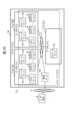
図1において、1は全体として本実施の形態によるクラウドシステムを示す。このクラウドシステム1は、それぞれ異なるアベイラビリティゾーンに設置された第1、第2及び第3のデータセンタ2A,2B,2Cを備えて構成される。なお、以下においては、第1~第3のデータセンタ2A~2Cを特に区別する必要がない場合には、これらを纏めてデータセンタ2と呼ぶものとする。(1) Configuration of a storage system according to this embodiment (1-1) Configuration of a storage system according to this embodiment In Fig. 1, 1 indicates a cloud system according to this embodiment as a whole. This
これらのデータセンタ2間は、専用ネットワーク3を介して相互に接続されている。また専用ネットワーク3には管理サーバ4が接続されると共に、管理サーバ4にはインターネット等のネットワーク5を介してユーザ端末6が接続されている。また、各データセンタ2A~2Cには、それぞれ分散ストレージシステムを構成する1又は複数台のストレージサーバ7と、1又は複数台のネットワークドライブ8とが配置されている。ストレージサーバ7の構成については後述する。These
ネットワークドライブ8は、SAS(Serial Attached SCSI(Small Computer System Interface))、SSD(Solid State Drive)、NVMe(Non Volatile Memory express)又はSATA(Serial ATA(Advanced Technology Attachment))などの大容量かつ不揮発性の記憶装置から構成される。各ネットワークドライブ8は、それぞれ同じデータセンタ2内のいずれかのストレージサーバ7に論理的に接続され、接続先のストレージサーバ7に対してそれぞれ物理的な記憶領域を提供する。The
ネットワークドライブ8は、各ストレージサーバ7内に収容されていても、ストレージサーバ7とは別個に設けられていてもよいが、以下においては、図3に示すように、ストレージサーバ7とは別個に設けられているものとする。各ストレージサーバ7は、LAN(Local Area Network)などのデータセンタ内ネットワーク34(図3)を介して同じデータセンタ2内の各ネットワークドライブ8とそれぞれ物理的に接続される。The network drives 8 may be housed within each
また各データセンタ2には、データベースアプリケーションなどのアプリケーション33(図3)が実装されたホストサーバ9も配置される。ホストサーバ9は物理的なコンピュータ装置、又は、仮想的なコンピュータ装置である仮想マシンなどから構成される。In addition, each
管理サーバ4は、CPU(Central Processing Unit)、メモリ及び通信装置などを内蔵する汎用のコンピュータ装置から構成され、各データセンタ2にそれぞれ配置された各ストレージサーバ7と、管理サーバ4とから構成されるストレージシステム10の管理者により、当該ストレージシステム10を管理するために利用される。The
管理サーバ4は、例えば、管理者の操作入力や、ユーザ端末6を介したストレージシステム10の利用者(ユーザ)からの要求に応じたコマンドを各データセンタ2のストレージサーバ7等に送信するようにして、これらストレージサーバ7に対する各種設定及びその設定の変更を行ったり、各データセンタ2のストレージサーバ7から必要な情報を収集する。The
ユーザ端末6は、ストレージシステム10のユーザが利用する通信端末装置であり、汎用のコンピュータ装置から構成される。ユーザ端末6は、ユーザの操作に応じた要求等をネットワーク5を介して管理サーバ4に送信したり、管理サーバ4から送信されてきた情報を表示する。The
図2は、ストレージサーバ7の物理構成を示す。ストレージサーバ7は、ホストサーバ9に実装されたアプリケーション33(図3)からのI/O要求に応じて、ネットワークドライブ8が提供する記憶領域にユーザデータをリード/ライト(読み書き)する機能を有する汎用のサーバ装置である。Figure 2 shows the physical configuration of the
図2に示すように、ストレージサーバ7は、内部ネットワーク20を介して相互に接続されたCPU21、データセンタ内通信装置22及びデータセンタ間通信装置23と、CPU21に接続されたメモリ24とをそれぞれ1以上備えて構成される。As shown in FIG. 2, the
CPU21は、ストレージサーバ7の動作制御を司るプロセッサである。またデータセンタ内通信装置22は、ストレージサーバ7が同じデータセンタ2内の他のストレージサーバ7と通信を行ったり、同じデータセンタ2内のネットワークドライブ8にアクセスするためのインタフェースであり、例えばLANカードやNIC(Network Interface Card)などから構成される。The
データセンタ間通信装置23は、ストレージサーバ7が専用ネットワーク3(図1)を介して他のデータセンタ2内のストレージサーバ7と通信を行うためのインタフェースであり、例えばNICやファイバーチャネルカードなどから構成される。The data
メモリ24は、例えばSRAM(Static RAM(Random Access Memory))やDRAM(Dynamic RAM)などの揮発性の半導体メモリから構成され、各種プログラムや必要なデータを一時的に保持するために利用される。メモリ24に格納されたプログラムをCPU21が実行することにより、後述のようなストレージサーバ7全体としての各種処理が実行される。後述するストレージ制御ソフト25もこのメモリ24に格納されて保持される。The
図3は、ストレージサーバ7の論理構成を示す。この図3に示すように、各データセンタ2に配置された各ストレージサーバ7は、それぞれSDS(Software Defined Storage)を構成する1又は複数のストレージコントローラ30を備える。ストレージコントローラ30は、メモリ24(図2)に格納されたストレージ制御ソフト25(図2)をCPU21(図2)が実行することにより具現化される機能部である。このストレージコントローラ30は、データプレーン31及びコントロールプレーン32を備える。Figure 3 shows the logical configuration of a
データプレーン31は、ホストサーバ9に実装されたアプリケーション33からのライト要求やリード要求(以下、適宜、これらを纏めてI/O(Input/Output)要求と呼ぶ)に応じて、データセンタ内ネットワーク34を介してネットワークドライブ8にユーザデータをリード/ライトする機能を有する機能部である。The
実際上、本ストレージシステム10では、ホストサーバ9に実装されたアプリケーション33に対して、ネットワークドライブ8が提供する物理的な記憶領域をストレージサーバ7内で仮想化した仮想的な論理ボリューム(以下、これをホストボリュームと呼ぶ)HVOLがユーザデータをリード/ライトするための記憶領域として提供される。また、このホストボリュームHVOLは、そのホストボリュームHVOLが作成されたストレージサーバ7内のいずれかのストレージコントローラ30と対応付けられる。In practice, in this
そしてデータプレーン31は、自身を備えるストレージコントローラ(以下、これを自ストレージコントローラと呼ぶ)30と対応付けられたホストボリュームHVOL内のライト先を指定したライト要求と、ライト対象のユーザデータとがホストサーバ9のアプリケーション33から与えられた場合、そのホストボリュームHVOL内のそのライト先として指定された仮想的な記憶領域に対して、自ストレージコントローラ30が実装されたストレージサーバ7に論理的に接続されたネットワークドライブ8が提供する物理的な記憶領域を動的に割り当て、かかるユーザデータをその物理領域に格納する。When the
またデータプレーン31は、ホストボリュームHVOL内のリード先を指定したリード要求がホストサーバ9のアプリケーション33から与えられた場合、ホストボリュームHVOL内のそのリード先に割り当てられた対応するネットワークドライブ8の対応する物理領域からユーザデータを読み出し、読み出したユーザデータをそのアプリケーション33に送信する。When a read request specifying a read destination within the host volume HVOL is given by an
コントロールプレーン32は、ストレージシステム10の構成を管理する機能を有する機能部である。例えば、コントロールプレーン32は、各データセンタ2にそれぞれどのようなストレージサーバ7が配置され、これらストレージサーバ7にどのネットワークドライブ8が論理的に接続されているかといった情報を図4に示すストレージ構成管理テーブル35を利用して管理する。The
この図4に示すように、ストレージ構成管理テーブル35は、データセンタID欄35A、サーバID欄35B及びネットワークドライブID欄35Cを備えて構成される。As shown in FIG. 4, the storage configuration management table 35 includes a data
そしてデータセンタID欄35Aには、各データセンタ2に対してそれぞれ付与されたそのデータセンタ2に固有の識別子(データセンタID)が格納される。またサーバID欄35Bは、対応するデータセンタ2に配置されたストレージサーバ7にそれぞれ対応させて区分されており、区分された各欄(以下、これらをサーバ欄と呼ぶ)にそれぞれ対応するストレージサーバ7に付与されたそのストレージサーバ7に固有の識別子(サーバID)が格納される。The data
さらにネットワークドライブID欄35Cは、各サーバID欄35Bにそれぞれ対応させて区分されており、対応するサーバID欄35BにサーバIDが格納されたストレージサーバ7と論理的に接続された(そのストレージサーバ7が利用可能な)すべてのネットワークドライブ8の識別子(ネットワークドライブID)がそれぞれ格納される。Furthermore, the network
従って、図4の例の場合、例えば「000」というデータセンタIDが付与されたデータセンタ2には、「000」というサーバIDが付与されたストレージサーバ7と、「001」というサーバIDが付与されたストレージサーバ7とが配置され、「000」というストレージサーバ7には、「000」というネットワークドライブIDが付与されたネットワークドライブ8と、「001」というネットワークドライブIDが付与されたネットワークドライブ8とがそれぞれ論理的に接続されていることが示されている。Therefore, in the example of Figure 4, for example, a
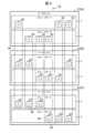
図5は、本ストレージシステム10におけるストレージコントローラ30の冗長化構成の構成例を示す。本ストレージシステム10において、ストレージサーバ7に実装された各ストレージコントローラ30は、それぞれ互いに異なるデータセンタ2内のいずれかのストレージサーバ7に実装された1又は複数の他のストレージコントローラ30と共に冗長化のための1つのグループ(以下、これを冗長化グループと呼ぶ)36として管理される。Figure 5 shows an example of a redundant configuration of
なお図5は、互いに異なるデータセンタ2内の3つのストレージコントローラ30により1つの冗長化グループ36が構成される例を示したものである。以下においてもこれら3つのストレージコントローラ30により1つの冗長化グループ36が構成されるものとして説明を進めるが、2又は4以上のストレージコントローラ30により冗長化グループ36を構成するようにしてもよい。Note that FIG. 5 shows an example in which one
冗長化グループ36では、各ストレージコントローラ30に優先順位が設定される。そして最も優先順位が高いストレージコントローラ30が、そのデータプレーン31(図3)がホストサーバ9からのI/O要求を受け付けることができる動作モード(現用系の状態であり、以下、これをアクティブモードと呼ぶ)に設定され、残りのストレージコントローラ30が、そのデータプレーン31がホストサーバ9からのI/O要求を受け付けない動作モード(待機系の状態であり、以下、これをスタンバイモードと呼ぶ)に設定される。図5では、アクティブモードに設定されたストレージコントローラ30が「A」で示され、スタンバイモードに設定されたストレージコントローラ30が「S」で示されている。In the
そして冗長化グループ36では、アクティブモードに設定されたストレージコントローラ30又はそのストレージコントローラ30が実装されたストレージサーバ7に障害が発生した場合などに、それまでスタンバイモードに設定されていた残りのストレージコントローラ30の中で最も優先順位が高いストレージコントローラ30の動作モードがアクティブモードに切り替えられる。これにより、アクティブモードに設定されたストレージコントローラ30が稼働し得なくなった場合にも、そのストレージコントローラ30が実行していたI/O処理をそれまでスタンバイモードに設定されていた他のストレージコントローラ30により引き継ぐことができる(フェイルオーバ機能)。In the
このようなフェイルオーバ機能を実現するため、同じ冗長化グループ36に属するストレージコントローラ30のコントロールプレーン32は、常に同一内容のメタデータを保持している。メタデータは、容量仮想化機能や、アクセス頻度の多いデータをより応答速度が速い記憶領域に移動させる階層記憶制御機能、格納されたデータの中から重複するデータを削除する重複排除機能、データを圧縮して記憶する圧縮機能、ある時点でのデータの状態を保持するスナップショット機能、及び、災害対策のために同期又は非同期で遠隔地にデータをコピーするリモートコピー機能などの各種機能に関する処理をストレージコントローラ30が実行するために必要な情報である。またメタデータには、図4について上述したストレージ構成管理テーブル35や、図8について後述するストレージコントローラ管理テーブル40、図9について後述するチャンクグループ管理テーブル41及び図11について後述するホストボリューム管理テーブル52なども含まれる。To realize such a failover function, the
そして構成変更などにより冗長化グループ36を構成するアクティブモードのストレージコントローラ30のメタデータが更新された場合、そのストレージコントローラ30のコントロールプレーン32(図3)により、更新前後のそのメタデータの差分が差分データとしてその冗長化グループ36を構成する他のストレージコントローラ30に転送され、この差分データに基づいて当該他のストレージコントローラ30において、そのストレージコントローラ30が保持するメタデータがそのストレージコントローラ30のコントロールプレーン32により更新される。これにより冗長化グループ36を構成する各ストレージコントローラ30のメタデータが常に同期した状態に維持される。When the metadata of an active
このように冗長化グループ36を構成する各ストレージコントローラ30が常に同じ内容のメタデータを保持することにより、アクティブモードに設定されたストレージコントローラ30や、当該ストレージコントローラ30が稼働するストレージサーバ7に障害が発生した場合にも、それまでそのストレージコントローラ30が実行していた処理を、そのストレージコントローラ30と同じ冗長化グループ36を構成する他のストレージコントローラ30により直ちに引き継ぐことができる。In this way, each
他方、図6は、ストレージシステム10における記憶領域の管理方法を示す。本ストレージシステム10では、各ネットワークドライブ8が提供する記憶領域が固定サイズ(例えば数100GB)の物理領域に分割されて管理される。以下においては、この物理領域を物理チャンク37と呼ぶ。On the other hand, FIG. 6 shows a method of managing storage areas in the
物理チャンク37は、それぞれ互いに異なるデータセンタ2内のいずれかのネットワークドライブ8内に定義された1又は複数の他の物理チャンク37と共に、ユーザデータを冗長化するための1つのグループ(以下、これをチャンクグループと呼ぶ)38として管理される。The
図6では、それぞれ互いに異なるデータセンタ2内にそれぞれ存在する3つの物理チャンク37(図中、斜線で示した各物理チャンク37)により1つのチャンクグループ38が構成されている例を示しており、以下においても異なるデータセンタ2内にそれぞれ存在する3つの物理チャンク37により1つのチャンクグループ38が構成されるものとして説明を進める。Figure 6 shows an example in which one
同じチャンクグループ38を構成する各物理チャンク37は、原則として、それぞれ同じ冗長化グループ36を構成するその物理チャンク37と同じデータセンタ2内のストレージコントローラ30に割り当てられる。In principle, each
従って、例えば、あるチャンクグループ38を構成する第1のデータセンタ2A内の物理チャンク37は、ある冗長化グループ36を構成する第1のデータセンタ2A内のストレージコントローラ30に割り当てられる。また、そのチャンクグループ38を構成する第2のデータセンタ2B内の物理チャンク37は、その冗長化グループ36を構成する第2のデータセンタ2B内のストレージコントローラ30に割り当てられ、そのチャンクグループ38を構成する第3のデータセンタ2C内の物理チャンク37は、その冗長化グループ36を構成する第3のデータセンタ2C内のストレージコントローラ30に割り当てられる。Therefore, for example, the
チャンクグループ38に対するユーザデータの書き込みは、予め設定されたデータ保護ポリシに従って行われる。本実施の形態のストレージシステム10に適用されるデータ保護ポリシとしては、ミラーリング及びEC(Erasure Coding)がある。「ミラーリング」は、ある物理チャンク37に格納されたユーザデータと全く同じユーザデータを、その物理チャンク37と同じチャンクグループ38を構成する他の物理チャンク37に格納する方式である。また「EC」としては、データローカリティを保証しない第1の方式と、データローカリティを保証する第2の方式とがあるが、本実施の形態では、データセンタ2内でのデータローカリティを保証する第2の方式を適用するものとする。User data is written to
すなわち本実施の形態のストレージシステム10では、チャンクグループ38におけるデータ保護ポリシとしてミラーリング及びECのいずれを指定された場合においても、ホストサーバ9に実装されたアプリケーション33(図3)が使用するユーザデータ及びそのユーザデータに関するメタデータを、そのアプリケーション33と同じデータセンタ2内で保持する。In other words, in the
このような本ストレージシステム10に適用されるECの第2の方式の一例について、図7を参照して具体的に説明する。なお、この例によるECの第2の方式の場合には、冗長化グループ36を構成する各ストレージコントローラ30に対して同じチャンクグループ38を構成する物理チャンク37をそれぞれ割り当てる必要がない。An example of the second EC method applied to the
以下においては、図7に示すように、第1のデータセンタ2A内のホストサーバが第1のストレージサーバ7A内のホストボリュームHVOLに第1のユーザデータD1(図中の「a」及び「b」から構成されるデータ)を書き込み、この第1のユーザデータD1が第1のストレージサーバ7A内の第1の物理チャンク37Aに格納されるものとする。In the following, as shown in FIG. 7, the host server in the
また第2のデータセンタ2B内の第2のストレージサーバ7B内には、第1の物理チャンク37Aと同じチャンクグループ38を構成する第2の物理チャンク37Bが存在し、第1の物理チャンク37における第1のユーザデータD1が格納された記憶領域と同じ第2の物理チャンク37B内の記憶領域に第2のユーザデータD2(図中の「c」及び「d」から構成されるデータ)が格納されているものとする。In addition, a second
同様に、第3のデータセンタ2C内の第3のストレージサーバ7C内には、第1の物理チャンク37Aと同じチャンクグループ38を構成する第3の物理チャンク37Cが存在し、第1の物理チャンク37Aにおける第1のユーザデータD1が格納された記憶領域と同じ第3の物理チャンク37C内の記憶領域に第3のユーザデータD3が格納されているものとする。Similarly, in a
かかる構成において、第1のデータセンタ2A内の第1のホストサーバ9Aに実装された第1のアプリケーション33Aが自身に割り当てられた第1のホストボリュームHVOL1に第1のユーザデータD1を書き込むと、その第1のユーザデータD1は対応するストレージコントローラ30Aのデータプレーン31Aによりそのまま第1の物理チャンク37Aに格納される。In this configuration, when a
また、かかるデータプレーン31Aは、その第1のユーザデータD1を「a」及び「b」という同じ大きさの2つの部分データD1A,D1Bに分割し、これら部分データD1Aのうちの一方の部分データD1A(図では「a」)を第2のデータセンタ2B内の第2の物理チャンク37Bを提供する第2のストレージサーバ7Bに転送し、他方の部分データD1B(図では「b」)を第3のデータセンタ2C内の第3の物理チャンク37Cを提供する第3のストレージサーバ7Cに転送する。The
さらに、かかるデータプレーン31Aは、第2のデータセンタ2B内の第2のストレージサーバ7Bの対応するストレージコントローラ30Bのデータプレーン31Bを介して第2の物理チャンク37Bから、第2のユーザデータD2を「c」及び「d」という同じ大きさの2つの部分データD2A,D2Bに分割したうちの一方の部分データD2A(図では「c」)を読み出す。またデータプレーン31Aは、第3のデータセンタ2C内の第3のストレージサーバ7Cの対応するストレージコントローラ30Cのデータプレーン31Cを介して第3の物理チャンク37Cから、第3のユーザデータD3を「e」及び「f」という同じ大きさの2つの部分データD3A,D3Bに分割したうちの一方の部分データD3A(図では「e」)を読み出す。そして、データプレーン31Aは、これら読み出した「c」という部分データD2Aと、「e」という部分データD3AとからパリティP1を生成し、生成したパリティP1を第1の物理チャンク37Aに格納する。Furthermore, the
第2のストレージサーバ7B内の第2の物理チャンク37Bと対応付けられたストレージコントローラ30Bのデータプレーン31Bは、第1のストレージサーバ7Aから「a」という部分データD1Aが転送されてくると、第3のデータセンタ2C内の第3のストレージサーバ7Cの対応するストレージコントローラ30Cのデータプレーン31Cを介して、第3の物理チャンク37Cから上述した「e」及び「f」という部分データD3A,D3Bの一方(図では「f」)を読み出す。また、かかるデータプレーン31Bは、読み出した「f」という部分データD3Bと、第1のストレージサーバ7Aから転送されてきた「a」という部分データD1AとからパリティP2を生成し、生成したパリティP2を第2の物理チャンク37Bに格納する。When partial data D1A named "a" is transferred from the
また第3のストレージサーバ7C内の第3の物理チャンク37Cと対応付けられたストレージコントローラ30Cのデータプレーン31Cは、第1のストレージサーバ7Aから「b」という部分データD1Bが転送されてくると、第2のデータセンタ2Bに配置された第2のストレージサーバ7Bの対応するストレージコントローラ30Bのデータプレーン31Bを介して、第2の物理チャンク37Bから上述した「c」及び「d」という部分データD2A,D2Bのうちの一方(図では「d」)を読み出す。また、かかるデータプレーン31Bは、読み出した「d」という部分データD2Bと、第1のストレージサーバ7Aから転送されてきた「b」という部分データD1BとからパリティP3を生成し、生成したパリティP3を第3の物理チャンク37Cに格納する。When partial data D1B "b" is transferred from the
以上の処理は、第2のデータセンタ2Bにおいて、第2のホストサーバ9Bに実装された第2のアプリケーション33Bが第2のストレージサーバ7Bの第2のホストボリュームHVOL2にユーザデータD2を書き込んだ場合や、第3のデータセンタ2Cにおいて、第3のホストサーバ9Cに実装された第3のアプリケーション33Cが第3のストレージサーバ7Cの第3のホストボリュームHVOL3にユーザデータD3を書き込んだ場合にも同様に行われる。The above processing is also performed when, in the
このようなユーザデータD1~D3の冗長化処理により、第1~第3のホストサーバ9A~9Cに実装された第1~第3のアプリケーション33A~33Cが使用する第1~第3のユーザデータD1~D3を冗長化しながら、その第1~第3のユーザデータD1~D3を常にその第1~第3のアプリケーション33A~33Cと同じ第1~第3のデータセンタ2A~2C内に保持することができる。ホストサーバ9に障害が発生した場合には、ホストサーバ9に格納されたユーザデータを、パリティと、そのパリティの生成の基となり他のホストサーバ9に格納されたユーザデータを用いて復元することができる。これにより第1~第3のアプリケーション33A~33Cが使用する第1~第3のユーザデータD1~D3の第1~第3のデータセンタ2A~2C間でのデータ転送を防止し、かかるデータ転送に起因するI/O性能の低下や通信コストの高コスト化を回避することができる。なお、ユーザデータ数やパリティ数は、2D1Pに限らず任意の数を設定することができる。By performing such a redundancy process for the user data D1 to D3, the first to third user data D1 to D3 used by the first to
このような冗長化グループ36(図5)やチャンクグループ38(図6)を管理するため、各ストレージコントローラ30のコントロールプレーン32は、図8に示すようなストレージコントローラ管理テーブル40と、図9に示すようなチャンクグループ管理テーブル41とを上述のメタデータの一部として管理している。To manage such redundancy groups 36 (Figure 5) and chunk groups 38 (Figure 6), the
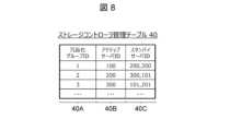
ストレージコントローラ管理テーブル40は、管理者やユーザ等により設定された上述の冗長化グループ36を管理するためのテーブルであり、図8に示すように、冗長化グループID欄40A、アクティブサーバID欄40B及びスタンバイサーバID欄40Cを備えて構成される。ストレージコントローラ管理テーブル40では、1つの行が1つの冗長化グループ36に対応する。The storage controller management table 40 is a table for managing the above-mentioned
そして冗長化グループID欄40Aには、対応する冗長化グループ36に対して付与された、その冗長化グループ36に固有の識別子(冗長化グループID)が格納され、アクティブサーバID欄40Bには、対応する冗長化グループ36の中でアクティブモードに設定されたストレージコントローラ30が実装されたストレージサーバ7のサーバIDが格納される。またスタンバイサーバID欄40Cには、その冗長化グループ36の中でスタンバイモードに設定されたストレージコントローラ30がそれぞれ実装されたストレージサーバ7のサーバIDが格納される。The redundancy
従って、図8の例の場合、「1」という冗長化グループIDが付与された冗長化グループ36では、アクティブモードに設定されたストレージコントローラ30が「100」というサーバIDが付与されたストレージサーバ7に実装され、スタンバイモードに設定された残りの2つのストレージコントローラ30がそれぞれ「200」というサーバIDが付与されたストレージサーバ7と、「300」というサーバIDが付与されたストレージサーバ7とに実装されていることが示されている。Therefore, in the example of Figure 8, in a
またチャンクグループ管理テーブル41は、管理者やユーザ等により設定された上述のチャンクグループ38を管理するためのテーブルであり、図9に示すように、チャンクグループID欄41A、データ保護ポリシ欄41B及び物理チャンクID欄41Cを備えて構成される。チャンクグループ管理テーブル41では、1つの行が1つのチャンクグループ38に対応する。The chunk group management table 41 is a table for managing the
そしてチャンクグループID欄41Aには、対応するチャンクグループ38に対して付与されたそのチャンクグループ38に固有の識別子(チャンクグループID)が格納され、データ保護ポリシ欄41Bには、そのチャンクグループ38に対して設定されたデータ保護ポリシが格納される。データ保護ポリシとしては、同じデータを格納する「ミラーリング」及び「ECの第2の方式」などがある。これらの方式では、ユーザデータを自データセンタ2内のストレージサーバ7に格納しているため、アベイラビリティ間通信を行うことなくユーザデータをリードできるため、リード性能が高いとともにネットワーク負荷が低い。The chunk
従って、図9の例の場合、「0」というチャンクグループIDが付与されたチャンクグループ38のデータ保護ポリシは「ミラーリング」であり、「100」という物理チャンクIDが付与された物理チャンク37と、「200」という物理チャンクIDが付与された物理チャンク37と、「300」という物理チャンクIDが付与された物理チャンク37とによりそのチャンクグループ38が構成されていることが示されている。すなわち、データを自データセンタ2内に格納するとともに、ミラーデータを他データセンタ2に転送して格納する。Therefore, in the example of FIG. 9, the data protection policy of
これらストレージコントローラ管理テーブル40や、チャンクグループ管理テーブル41は、例えばいずれかの冗長化グループ36にフェイルオーバが発生などして冗長化グループ36の構成が変更した場合や、新たなネットワークドライブ8がストレージサーバ7に論理的に接続された場合などに、そのストレージコントローラ管理テーブル40や、チャンクグループ管理テーブル41を保持するストレージコントローラ30のコントロールプレーン32により更新される。The storage controller management table 40 and chunk group management table 41 are updated by the
図10は、ホストサーバ9に実装されたアプリケーション33からストレージサーバ7内のホストボリュームHVOLへのアクセスの制御手法を示す。本ストレージシステム10では、冗長化グループ36を構成する各ストレージコントローラ30にそれぞれ対応付けて、そのストレージコントローラ30が実装されたストレージサーバ7内にそれぞれホストボリュームHVOLが作成される。また、これらのホストボリュームHVOLが同一のホストボリュームHVOLとしてホストサーバ9に実装されたアプリケーション33に提供される。以下においては、冗長化グループ36を構成する各ストレージコントローラ30にそれぞれ対応させて作成されたホストボリュームHVOLの集合体をホストボリュームグループ50と呼ぶ。Figure 10 shows a method of controlling access from an
そしてアプリケーション33は、各ストレージサーバ7内の各ホストボリュームHVOLにログインしたときにそのホストボリュームHVOLと対応付けられたストレージコントローラ30から通知される情報に基づいて、提供された各ホストボリュームHVOLへのパス51のうち、対応する冗長化グループ36においてアクティブモードに設定されたストレージコントローラ30と対応付けられたホストボリュームHVOLへのパス51をユーザデータへのアクセスに用いるパス51として最適化(「Optimized」)パスに設定し、これ以外のホストボリュームHVOLへのパス51を非最適化(「Non-Optimized」)パスに設定する。またアプリケーション33は、ユーザデータへのアクセスは常に最適化パスを介して行う。従って、アプリケーション33からホストボリュームHVOLへのアクセスは、常に、アクティブモードに設定されたストレージコントローラ30と対応付けられたホストボリュームHVOLに対して行われる。Then, based on information notified from the
この場合において、アクティブモードに設定されたストレージコントローラ30は、上述のようにそのストレージコントローラ30が実装されたストレージサーバ7に接続された、同じデータセンタ2内のネットワークドライブ8(図1)が提供する物理的な記憶領域にユーザデータを格納するため、そのユーザデータが常にそのアプリケーション33と同じデータセンタ2内に存在する。これによりアプリケーション33がユーザデータにアクセスする際にデータセンタ2間でのデータ転送が発生せず、かかるデータ転送に起因するI/O性能の低下や通信コストの高コスト化を回避することができる。In this case, the
図11は、上述のようにストレージサーバ7に作成されたホストボリュームHVOLを管理するために利用されるホストボリューム管理テーブル52を示す。このホストボリューム管理テーブル52は、ホストサーバ9に実装されたアプリケーション33に対して同一のホストボリュームHVOLとして提供される複数のホストボリュームHVOLのうち、アクティブモードに設定されたストレージコントローラ30と対応付けられたホストボリューム(以下、これをオーナホストボリュームと呼ぶ)HVOLの所在を管理するために利用されるテーブルである。Figure 11 shows a host volume management table 52 used to manage the host volumes HVOLs created in the
実際上、ホストボリューム管理テーブル52は、ホストボリューム(HVOL)ID欄52A、オーナデータセンタID欄52B、オーナサーバID欄52C及びサイズ欄52Dを備えて構成される。ホストボリューム管理テーブル52では、1つの行が、ホストサーバ9に実装されたアプリケーション33に提供される1つのオーナホストボリュームHVOLに対応する。In practice, the host volume management table 52 is configured with a host volume (HVOL)
そしてホストボリュームID欄52Aには、ホストサーバ9に実装されたアプリケーション33に提供されるホストボリューム(オーナホストボリュームを含む)HVOLのボリュームIDが格納され、サイズ欄52Dには、そのホストボリュームHVOLのボリュームサイズが格納される。またオーナデータセンタID欄52Bには、そのホストボリュームHVOLのうちのオーナホストボリュームHVOLが存在するデータセンタ(オーナデータセンタ)2のデータセンタIDが格納され、オーナサーバID欄52Cには、そのオーナホストボリュームHVOLが作成されたストレージサーバ(オーナサーバ)7のサーバIDが格納される。The host
従って、図11の例では、アプリケーション33が「1」というホストボリュームIDで認識するホストボリュームHVOLのサイズは「100GB」であり、そのオーナホストボリュームHVOLが「1」というデータセンタIDが付与されたデータセンタ2内の「100」というサーバIDが付与されたストレージサーバ7内に作成されていることが示されている。Therefore, in the example of Figure 11, the size of the host volume HVOL recognized by
(1-2)障害発生時におけるフェイルオーバの流れ
次に、かかる本実施の形態のストレージシステム10において、データセンタ単位の障害が発生した場合に実行されるフェイルオーバの処理の流れについて説明する。図12は、図5に示した平常状態から、いずれかのデータセンタ2(ここでは第1のデータセンタ2Aとする)にデータセンタ単位の障害が発生した場合に実行されるフェイルオーバの様子を示す。(1-2) Flow of Failover When a Fault Occurs Next, a flow of failover processing executed when a fault occurs on a data center basis in the
本ストレージシステム10において、各ストレージコントローラ30のコントロールプレーン32(図3)は、自ストレージコントローラ30と同じ冗長化グループ36を構成する他のストレージコントローラ30のコントロールプレーン32との間でハートビート信号を所定周期でやり取りすることにより、これらの他のストレージコントローラ30がそれぞれ実装された各ストレージサーバ7の生死監視を行っている。そしてコントロールプレーン32は、監視先のストレージサーバ7のコントロールプレーン32からのハートビート信号を一定期間受信できなかった場合、そのストレージサーバ7に障害が発生したと判断して、そのストレージサーバ(以下、これを障害ストレージサーバと呼ぶ)7を閉塞する。In this
また、閉塞された障害ストレージサーバ7にいずれかの冗長化グループ36のアクティブモードのストレージコントローラ30が存在していた場合には、その冗長化グループ36において、そのストレージコントローラ30の次に優先順位が高いストレージコントローラ30の動作モードがアクティブモードに切り替えられ、元のアクティブモードのストレージコントローラ(以下、これを元アクティブストレージコントローラと呼ぶ)30が実行していた処理が、新たにアクティブモードに設定されたストレージコントローラ(以下、これを新規アクティブストレージコントローラと呼ぶ)30に引き継がれる。In addition, if the blocked failed
例えば、図12の左端に示した冗長化グループ36や、左端から4番目の冗長化グループ36では、障害が発生した第1のデータセンタ2Aに配置されていたストレージコントローラ30がアクティブモードであったため、同じ冗長化グループ36を構成する第2のデータセンタ2B内のストレージコントローラ30(図12の斜線で示された各ストレージコントローラ30)の動作モードがアクティブモードに切り替えられた例を示している。従って、この場合、閉塞されたストレージサーバ7に実装された元アクティブストレージコントローラ30がそれまで実行していたI/O処理を、第2のデータセンタ2B内の新規アクティブストレージコントローラ30が引き継いで実行することになる。For example, in the
このため、元アクティブストレージコントローラ30の処理を引き継いだ新規アクティブストレージコントローラ30は、ユーザデータが格納されていた物理チャンク37に適用されていたデータ保護ポリシが上述のECの第2の方式であった場合、障害が発生していない残りのデータセンタ2B,2Cに存在するデータやパリティ等によってユーザデータを復元する。また、かかる新規アクティブストレージコントローラ30は、復元したユーザデータを、そのユーザデータが元々格納されていた障害ストレージサーバ内のホストボリューム(以下、これを障害ホストボリュームと呼ぶ)HVOLと同じホストボリュームグループ50(図10)を構成する自ストレージサーバ7内のホストボリュームHVOLと対応付けられた物理チャンク37(図6)に格納する。データ保護ポリシがミラーリングであった場合には、ミラーデータをユーザデータとして使用する。データセンタ2が異なる場合には、ユーザデータとなったミラーデータを、新規アクティブストレージコントローラ30と同じデータセンタ2に移動させる。Therefore, if the data protection policy applied to the
さらに管理サーバ4は、いずれかのデータセンタ2においてデータセンタ単位の障害や、ストレージサーバ7単位の障害が発生したことを検知した場合、図13に示すように、障害が発生したストレージサーバ(障害ストレージサーバ)7内のホストボリューム(障害ホストボリューム)HVOLにユーザデータのリード/ライトを行っていたホストサーバ9のアプリケーション33(以下、これを障害アプリケーション33と呼ぶ)と同じアプリケーション33を、かかる新規アクティブストレージコントローラ30が存在するデータセンタ2内のホストサーバ9で起動し、そのアプリケーション33にかかる障害アプリケーション33がそれまで実行していた処理を引き継がせる。Furthermore, when the
そして障害アプリケーション33の処理を引き継いだアプリケーション33から、新規アクティブストレージコントローラ30と対応付けられたホストボリュームHVOLへのパス51が最適化(「Optimized」)パスに設定され、これ以外の当該ホストボリュームHVOLへのパス51が非最適化(「Non-Optimized」)パスに設定される。これにより障害アプリケーション33の処理を引き継いだアプリケーション33が、復元されたユーザデータにアクセスすることができるようになる。Then, from the
このように本ストレージシステム10では、障害発生時に元アクティブストレージコントローラ30の処理を引き継いだ新規アクティブストレージコントローラ30と同じデータセンタ2内で障害アプリケーション33と同じアプリケーション33を起動し、そのアプリケーション33が処理を継続できるようにするため、各データセンタ2内のホストサーバ9から構成されるグループ(以下、これをホストサーバグループと呼ぶ)内では、各ホストサーバ9がいずれも同じアプリケーション33及びそのアプリケーション33が処理を実行するために必要な情報(以下、これをアプリケーションメタ情報と呼ぶ)を保持している。In this manner, in this
そしてホストサーバグループにおいて、いずれかのホストサーバ9に実装されたいずれかのアプリケーション33のアプリケーションメタ情報が更新された場合には、更新前後のそのアプリケーションメタ情報の差分を差分データとしてホストサーバグループに属する他のホストサーバ9に転送する。また、かかる他のホストサーバ9は、かかる差分データが転送されてくると、この差分データに基づいてそのホストサーバ9が保持するアプリケーションメタ情報を更新する。これにより、同じホストサーバグループを構成する各ホストサーバ9がそれぞれ保持するアプリケーションメタ情報の内容が常に同じ状態に維持される。In the host server group, when application meta information for any
このようにホストサーバグループを構成する各ホストサーバ9が常に同じ内容のアプリケーションメタ情報を保持することにより、いずれかのデータセンタ2のホストサーバ9やストレージサーバ7が障害により稼働し得なくなった場合においても、それまでそのホストサーバ9に実装されたアプリケーション33が実行していた処理を、他のデータセンタ2のホストサーバ9に実装された同じアプリケーション33により直ちに処理を引き継ぐことが可能となる。In this way, each
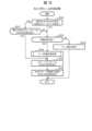
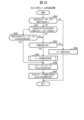
図14は、ストレージコントローラ30のコントロールプレーン32が、そのストレージコントローラ30と同じ冗長化グループ36を構成する他のストレージコントローラ30が実装されたストレージサーバ7の障害(データセンタ単位の障害を含む)を検出した場合に実行するサーバ障害復旧処理の流れを示す。Figure 14 shows the flow of server failure recovery processing that is executed when the
コントロールプレーン32は、自ストレージコントローラ30と同じ冗長化グループ36を構成する他のストレージコントローラ30のコントロールプレーン32からのハートビート信号を一定時間受信できなかった場合、この図14に示すサーバ障害復旧処理を開始する。If the
そして、コントロールプレーン32は、まず、ハートビート信号を一定時間受信できなかったストレージコントローラ30(以下、これを障害ストレージコントローラ30と呼ぶ)が実装されたストレージサーバ7を閉塞するための閉塞処理を実行する(S1)。この閉塞処理には、例えば図4について上述したストレージ構成管理テーブル35の更新などの処理も含まれる。Then, the
続いて、コントロールプレーン32は、ストレージコントローラ管理テーブル40(図8)を参照して、障害ストレージコントローラ30が、自ストレージコントローラ30が属する冗長化グループ36においてアクティブモードに設定されたストレージコントローラであるか否かを判断する(S2)。Then, the
そしてコントロールプレーン32は、この判断で肯定結果を得ると、自身で管理しているメタデータに基づいて、自ストレージコントローラ30が属する冗長化グループ36において、障害ストレージコントローラ30の次に自ストレージコントローラ30の優先順位が高いか否かを判断する(S3)。If the
そしてコントロールプレーン32は、この判断で肯定結果を得ると、障害ストレージコントローラ30がそれまで行っていた処理を自ストレージコントローラ30に引き継がせるためのフェイルオーバ処理を実行する(S4)。このフェイルオーバ処理には、自ストレージコントローラ30の動作モードをアクティブモードに切り替えることや、自ストレージコントローラ30がアクティブモードとなったことを同じ冗長化グループ36内の障害ストレージコントローラ30以外のストレージコントローラ30に通知すること、及び、図8について上述したストレージコントローラ管理テーブル40や、図9について上述したチャンクグループ管理テーブル41及び図11について上述したホストボリューム管理テーブル52を含む必要なメタデータを更新することなどが含まれる。If the
次いで、コントロールプレーン32は、障害ストレージコントローラ30と対応付けられたホストボリューム(以下、これを障害ホストボリュームと呼ぶ)HVOLと同じホストボリュームグループ50を構成する、自ストレージコントローラ30が実装されたストレージサーバ7内のホストボリューム(以下、これをフェイルオーバ先ホストボリュームと呼ぶ)HVOLへのパスを最適化(「Optimized」)パスに設定する(S5)。Next, the
この結果、この後、障害が発生したデータセンタ2で障害ホストボリュームHVOLにデータをリード/ライトしていたアプリケーション33と同じアプリケーション33が、そのコントロールプレーン32が存在するデータセンタ2内で管理サーバ4により起動されて、当該アプリケーション33が自ストレージコントローラ30にログインしてきたときに、そのコントロールプレーン32は自ストレージコントローラ30内の対応するホストボリュームHVOLへのパスを最適化(「Optimized」)パスに設定するようそのアプリケーション33に通知する。これにより、そのアプリケーション33が当該通知に応じてそのホストボリュームHVOLへのパスを最適化(「Optimized」)パスに設定する。以上によりこのサーバ障害復旧処理が終了する。As a result, when the
一方、コントロールプレーン32は、ステップS2で否定結果を得た場合には、自ストレージコントローラ30が属する冗長化グループ36の中で最も優先順位が高いストレージコントローラ30(ここではアクティブモードのストレージコントローラ30)に対して、障害ストレージコントローラ30が実装されたストレージサーバ7を閉塞した旨を通知する(S6)。On the other hand, if the
この結果、この通知を受信したストレージコントローラ30は、この通知の内容に応じて図8について上述したストレージコントローラ管理テーブル40等を含む必要なメタデータの更新を行うなどの所定の処理を実行する。以上により、このサーバ障害復旧処理が終了する。As a result, the
またコントロールプレーン32は、ステップS3で否定結果を得た場合には、自ストレージコントローラ30が属する冗長化グループ36の中で障害ストレージコントローラ30の次に優先順位が高いストレージコントローラ30に対して、障害ストレージコントローラ30が実装されたストレージサーバ7を閉塞した旨を通知する(S6)。If the
この結果、この通知を受信したストレージコントローラ30のコントロールプレーン32により、ステップS4及びステップS5と同様の処理が実行される。そして、この後、このサーバ障害復旧処理が終了する。As a result, the
(1-3)ホストボリュームの作成の流れ
次に、ユーザが所望するデータセンタ2内に所望するボリュームサイズのオーナホストボリュームHVOLを作成するまでの流れについて説明する。(1-3) Flow of Creating a Host Volume Next, a flow of creating an owner host volume HVOL of a desired volume size in a
図15は、所定操作によりユーザ端末6(図1)に表示させ得るホストボリューム作成画面60の構成例を示す。このホストボリューム作成画面60は、ホストサーバ9に実装されたアプリケーション33に提供するホストボリュームHVOLのうち、アクティブモードのストレージコントローラ30と対応付けるホストボリューム(オーナホストボリューム)HVOLをユーザが作成するための画面である。Figure 15 shows an example of the configuration of a host
このホストボリューム作成画面60は、ボリューム番号指定欄61、ボリュームサイズ指定欄62及び作成先データセンタ指定欄63と、OKボタン64とを備えて構成される。This host
そしてホストボリューム作成画面60では、ユーザがユーザ端末6を操作することによって、そのとき作成しようとするオーナホストボリュームHVOLのボリュームID(ここでは番号)をボリューム番号指定欄61に入力することで指定することができ、そのオーナホストボリュームHVOLのボリュームサイズをボリュームサイズ指定欄62に入力することで指定することができる。Then, on the host
またホストボリューム作成画面60では、作成先データセンタ指定欄63の右側に設けられたプルダウンメニュー65をクリックすることによって各データセンタ2のデータセンタIDが掲載されたプルダウンメニュー66を表示させることができる。In addition, on the host
そしてユーザは、このプルダウンメニュー66に表示されたデータセンタIDの中から所望するデータセンタ2のデータセンタIDをクリックにより選択することによって、そのデータセンタ2をオーナホストボリュームHVOLの作成先のデータセンタ2として指定することができる。このとき、選択されたデータセンタ2のデータセンタIDが作成先データセンタ指定欄63に表示される。The user can then select the data center ID of the desired
そしてホストボリューム作成画面60では、上述のようにしてオーナホストボリュームHVOLのボリュームID、ボリュームサイズ及び作成先のデータセンタ2を指定した上でOKボタン64をクリックすることによって、そのボリュームID及びそのボリュームサイズのオーナホストボリュームHVOLをそのデータセンタ2に作成すべきことを管理サーバ4に指示することができる。Then, on the host
実際上、ホストボリューム作成画面60のOKボタン64がクリックされると、そのときホストボリューム作成画面60上でユーザが指定したボリュームID、ボリュームサイズ及び作成先のデータセンタ2の各情報を含むボリューム作成要求がそのホストボリューム作成画面60を表示していたユーザ端末6において作成され、作成されたボリューム作成要求が管理サーバ4(図1)に送信される。In practice, when the
そして管理サーバ4は、かかるボリューム作成要求が与えられると、図16に示す処理手順に従って、要求されたボリュームID及びボリュームサイズのオーナホストボリュームHVOLを、指定されたデータセンタ2内のいずれかのストレージサーバ7内に作成する。When the
実際上、管理サーバ4は、かかるボリューム作成要求が与えられるとこの図16に示すホストボリューム作成処理を開始し、まず、ボリューム作成要求においてオーナホストボリュームHVOLの作成先として指定されたデータセンタ2(以下、これを指定データセンタ2と呼ぶ)内に、ユーザにより指定されたボリュームサイズのオーナホストボリュームHVOLを作成可能な容量をもつストレージサーバ7が存在するか否かを判断する(S10)。In practice, when such a volume creation request is given, the
具体的に、管理サーバ4は、指定データセンタ2の各ストレージサーバ7にそれぞれ実装されたいずれかのストレージコントローラ30に対して、そのストレージサーバ7の容量と、現在の使用容量とをそれぞれ問い合わせる。そして管理サーバは4、この問合わせに対してこれらストレージコントローラ30のコントロールプレーン32からそれぞれ通知されたこれらストレージサーバ7の容量及び現在の使用容量に基づいて、指定されたボリュームサイズのオーナホストボリュームHVOLを作成可能か否かを判定する。Specifically, the
そして管理サーバ4は、この判断で肯定結果を得ると、かかるオーナホストボリュームHVOLを作成可能なストレージサーバ7において、そのオーナホストボリュームHVOLと対応付けるストレージコントローラ30(例えば既存のストレージコントローラ30又は新たに作成したストレージコントローラ30)と同じ冗長化グループ36を構成する他の各ストレージコントローラ30がそれぞれ実装された他のデータセンタ2内の各ストレージサーバ7が、いずれも指定されたボリュームサイズのホストボリュームHVOLを作成可能か否かを上述のオーナホストサーバHVOLの場合と同様にして判定する(S11)。If the
そして管理サーバ4は、この判定で肯定結果を得ると、ステップS10でオーナホストボリュームHVOLを作成可能と判定されたストレージサーバ7のうち、ステップS11でも肯定結果が得られたストレージサーバ7の中から1つのストレージサーバ7を選択し、そのストレージサーバ7においてオーナホストボリュームHVOLと対応付けるストレージコントローラ30に対して、かかるオーナホストボリュームHVOLの作成指示を与える(S15)。これにより、そのストレージコントローラ30により、指定されたボリュームサイズのオーナホストボリュームHVOLがそのストレージコントローラ30と対応付けてそのストレージサーバ7内に作成される。また、そのストレージコントローラ30の動作モードがアクティブモードに設定される。If the
また管理サーバ4は、この後、そのストレージコントローラ30と同じ冗長化グループ36を構成する他のデータセンタ2内の各ストレージコントローラ30に対してもかかるオーナホストボリュームHVOLと同じボリュームサイズのホストボリュームHVOLの作成指示をそれぞれ与える(S16)。これにより、これらのストレージコントローラ30によりそのオーナホストボリュームHVOLと同じボリュームサイズのホストボリュームHVOLがこれらのストレージコントローラ30とそれぞれ対応付けて、これらストレージコントローラ30と同じストレージサーバ4内にそれぞれ作成される。また、これらストレージコントローラ30の動作モードがスタンバイモードに設定される。The
なお、上述のステップS15及びステップS16において、各データセンタ2内にそれぞれ新たに作成した各ホストボリュームHVOL(オーナホストボリュームHVOLを含む)とストレージコントローラ30との対応付けや、これらのホストボリュームHVOLとそれぞれ対応付けられるストレージコントローラ30の動作モード(アクティブモード又はスタンバイモード)の設定は、ストレージシステム10の管理者やユーザが手動で行うようにしてもよい。以下においても同様である。In addition, in the above-mentioned steps S15 and S16, the association of each host volume HVOL (including the owner host volume HVOL) newly created in each
他方、管理サーバ4は、ステップS10やステップS11の判断で否定結果を得た場合には、指定データセンタ2内の各ストレージサーバ7のうち、指定ホストボリュームHVOLを作成可能となるまで容量を拡張可能なストレージサーバ7が存在するか否かを判断する(S12)。On the other hand, if the
具体的に、管理サーバ4は、指定データセンタ2のいずれかのストレージサーバ7に実装されたいずれかのストレージコントローラ30に対して指定データセンタ2内の各ストレージサーバ7にそれぞれ論理的に接続されているネットワークドライブ8(図1)の数を問い合わせる。これは、ストレージサーバ7に論理的に接続可能なネットワークドライブ8の数は決まっているため、各ストレージサーバ7に対して追加的にネットワークドライブ8を接続して容量を拡張できるか否かを確認するためである。Specifically, the
また管理サーバ4は、かかるストレージコントローラ30に対して、指定データセンタ2に配置され、いずれのストレージサーバ7にも論理的に接続されていないネットワークドライブ8の数及びこれらネットワークドライブ8の容量も問い合わせる。そして管理サーバ4は、上述のようにして得た各情報に基づいて、指定データセンタ2内のネットワークドライブ8を追加的に接続することで、指定ホストボリュームHVOLを作成可能となるまで容量を拡張可能なストレージサーバ7が指定データセンタ2内に存在するか否かを判定する。The
この際、管理サーバ4は、あるストレージサーバ7が拡張可能である場合には、そのストレージサーバ7においてオーナホストボリュームHVOLを対応付けようとするストレージコントローラ30と冗長化グループ36を構成する他のストレージコントローラ30がそれぞれ実装された他のデータセンタ2のストレージサーバ7についても同じ容量を拡張可能であるか否かを判定する。これは、これらのストレージサーバ7についてもオーナストレージコントローラ30と同じボリュームサイズのホストボリュームHVOLを作成する必要があるためである。At this time, if a
そして管理サーバ4は、ステップS12の判断で否定結果を得ると、エラー通知を上述のボリューム作成要求の送信元のユーザ端末6に送信し(S13)、この後、このボリューム作成処理を終了する。この結果、かかるエラー通知に基づいて、指定ホストボリュームHVOLを作成できない旨の警告がそのユーザ端末6に表示される。If the
これに対して、管理サーバ4は、ステップS12の判断で肯定結果を得ると、ステップS12において容量を拡張可能(他のデータセンタ2内の対応するストレージサーバ7の容量拡張を含む)と判定した指定データセンタ2内のストレージサーバ7の中から1つのストレージサーバ7を選択し、選択したストレージサーバ7(以下、これを選択ストレージサーバ7と呼ぶ)に対してネットワークドライブ8を追加的に論理接続することによりその選択ストレージサーバ7の容量を拡張するサーバ容量拡張処理を実行する(S14)。In response to this, if the
また管理サーバ4は、容量を拡張した選択ストレージサーバ7内のオーナホストボリュームHVOLと対応付けようとするストレージコントローラ30に対して、かかるオーナホストボリュームHVOLの作成指示を与える(S15)。これにより、そのストレージコントローラ30により指定されたボリュームサイズのオーナホストボリュームHVOLがそのストレージコントローラ30と対応付けてそのストレージコントローラ30と同じストレージサーバ7内に作成される。また、そのストレージコントローラ30の動作モードがアクティブモードに設定される。The
また管理サーバ4は、この後、そのストレージコントローラ30と同じ冗長化グループ36を構成する他のデータセンタ2内の各ストレージコントローラ30に対してもかかるオーナホストボリュームHVOLと同じボリュームサイズのホストボリュームHVOLの作成を指示する(S16)。これにより、これらのストレージコントローラ30によりオーナホストボリュームHVOLと同じボリュームサイズのホストボリュームHVOLが、これらのストレージコントローラ30とそれぞれ対応付けてこれらストレージコントローラ30と同じストレージサーバ7内にそれぞれ作成される。また、これらストレージコントローラ30の動作モードがスタンバイモードに設定される。The
そして管理サーバ4は、この後、このホストボリューム作成処理を終了する。Then,
なお、このホストボリューム作成処理のステップS14で管理サーバ4により実行されるサーバ容量拡張処理の流れを図17に示す。The flow of the server capacity expansion process executed by
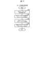
管理サーバ4は、図16のステップS14に進むとこの図17に示すサーバ容量拡張処理を開始し、まず、上述のオーナホストボリュームHVOLが属するホストボリュームグループ50(図10)を構成する各ホストボリュームHVOL(オーナホストボリュームHVOLを含む)とそれぞれ対応付けようとする各ストレージコントローラ30がそれぞれ実装された各データセンタ2内のストレージサーバ7(以下、これらのストレージサーバ7を容量拡張対象ストレージサーバ7と呼ぶ)の拡張容量をそれぞれ決定する(S20)。When the
続いて、管理サーバ4は、各容量拡張対象ストレージサーバ7の容量を等しく拡張できるように、これらの容量拡張対象ストレージサーバ7にそれぞれ論理的に接続するネットワークドライブ8を決定し(S21)、決定したネットワークドライブ8をそれぞれ対応する容量拡張対象ストレージサーバ7に論理的に接続する(S22)。Next, the
具体的に、管理サーバ4は、かかるホストボリュームグループを構成する各ホストボリュームHVOLをそれぞれ対応付ける各データセンタ2のストレージコントローラ30に対して、そのネットワークドライブ8を論理的に接続したことを通知する。また管理サーバ4は、本ストレージシステム10内の各冗長化グループ36のアクティブモードのストレージコントローラ30に対して、図4について上述したストレージ構成管理テーブル35の容量拡張対象ストレージサーバ7に対応するネットワークドライブID欄35Cに、そのとき論理的に接続したネットワークドライブ8のネットワークドライブIDを追加した状態に更新するよう指示を与える。Specifically, the
次いで、管理サーバ4は、各容量拡張対象ストレージサーバ7にそれぞれ接続した各ネットワークドライブ8がそれぞれ提供する記憶領域間でチャンクグループ38(図6)を作成し、作成したチャンクグループ38を図9について上述したチャンクグループ管理テーブル41に登録した状態に更新するよう、本ストレージシステム10内の各冗長化グループ36のアクティブモードのストレージコントローラ30にそれぞれ指示を与える(S23)。そして管理サーバ4は、この後、このサーバ容量拡張処理を終了してホストボリューム作成処理のステップS15に進む。Then, the
(1-4)サーバ使用容量監視処理の流れ
他方、図18は、各データセンタ2において、いずれかのストレージサーバ7に実装された特定のストレージコントローラ30のコントロールプレーン(以下、これを特定コントロールプレーンと呼ぶ)32によりそれぞれ定期的に実行されるサーバ使用容量監視処理の流れを示す。(1-4) Flow of Server Usage Capacity Monitoring Process On the other hand, FIG. 18 shows the flow of server usage capacity monitoring process that is periodically executed by the control plane (hereinafter referred to as the specific control plane) 32 of a
特定コントロールプレーン32は、この図18に示す処理手順に従って自ストレージコントローラ30が存在するデータセンタ(以下、これを自データセンタと呼ぶ)2内の各ストレージサーバ7の使用容量を監視し、いずれかのストレージサーバ7の使用容量が予め設定された閾値(以下、これを使用容量閾値と呼ぶ)を超過した場合に、そのストレージサーバ7の容量を拡張するための処理を実行する。The
実際上、特定コントロールプレーン32は、この図18に示すサーバ容量監視処理を開始すると、まず、自データセンタ2内の各ストレージサーバ7に実装されたいずれかのストレージコントローラ30から、そのストレージサーバ7の容量と、現在の使用容量とをそれぞれ取得する。この際、自ストレージコントローラ30が実装されたストレージサーバ7の容量及び現在の使用容量も取得する(S30)。In practice, when the
続いて、特定コントロールプレーン32は、取得したこれらの情報に基づいて、自データセンタ2内のいずれかのストレージサーバ7の使用容量が上述の使用容量閾値を超過したか否かを判断する(S31)。そして、特定コントロールプレーン32は、この判断で否定結果を得るとこのストレージサーバ使用容量監視処理を終了する。Then, based on the acquired information, the
これに対して、特定コントロールプレーン32は、ステップS31の判断で否定結果を得ると、使用容量が使用容量閾値を超過したストレージサーバ7(以下、これを使用容量超過ストレージサーバ7と呼ぶ)は拡張可能か否かを、図16について上述したホストボリューム作成処理のステップS12と同様にして判断する(S32)。In response to this, if the
そして、特定コントロールプレーン32は、この判断で肯定結果を得ると、図17について上述したサーバ容量拡張処理と同様の処理を実行することにより、その使用容量超過ストレージサーバ7の容量と、使用容量超過ストレージサーバ7に実装されたストレージコントローラ30と冗長化グループ36を構成する他のストレージコントローラ30が実装されたストレージサーバ7の容量とをそれぞれ拡張し(S33)、この後、このサーバ使用容量監視処理を終了する。If the
これに対して、特定コントロールプレーン32は、ステップS32の判断で否定結果を得ると、使用容量超過ストレージサーバ7と同一又は別のデータセンタ2のストレージサーバ7であって、使用容量超過ストレージサーバ7内のいずれかのホストボリュームHVOLを移動可能な空き容量を有するストレージサーバ7にそのホストボリュームHVOLを移動させるホストボリューム移動処理を実行し(S34)、この後、このサーバ使用容量監視処理を終了する。In response to this, if the
なお、かかるホストボリューム移動処理の具体的な処理内容を図19に示す。特定コントロールプレーン32は、サーバ使用容量監視処理のステップS34に進むと、この図19に示すホストボリューム移動処理を開始する。The specific processing contents of this host volume migration process are shown in FIG. 19. When the
そして特定コントロールプレーン32は、まず、サーバ使用容量監視処理のステップS30で取得した自データセンタ2内の各ストレージサーバ7の容量及び現在の使用容量に基づいて、自データセンタ2内のストレージサーバ7であって、使用容量超過ストレージサーバ7内のいずれかのホストボリュームHVOLを移動可能な程度の空き容量を有するストレージサーバ7の中から1つのストレージサーバ7を選択する(S40)。Then, the
そして特定コントロールプレーン32は、このステップS40において、そのようなストレージサーバ7を選択できたか否かを判断し(S41)、選択できた場合にはステップS43に進む。Then, in step S40, the
これに対して特定コントロールプレーン32は、ステップS41の判断で否定結果を得ると、自データセンタ2とは別の各データセンタ2内のいずれかのストレージサーバ7のいずれかのストレージコントローラ30のコントロールプレーン32にそのデータセンタ2内の各ストレージサーバ7の容量及び現在の使用容量を問い合わせることにより取得する。そして管理サーバ4は、取得したこれらの情報に基づいて、自データセンタ2とは別のデータセンタ2内のストレージサーバ7の中から、使用容量超過ストレージサーバ7内のいずれかのホストボリュームHVOLを移動可能な空き容量を有するストレージサーバ7を選択する(S42)。In response to this, if the
続いて、特定コントロールプレーン32は、使用容量超過ストレージサーバ7内のホストボリュームHVOLの中から他のストレージサーバ7に移動する移動対象のホストボリューム(以下、これを移動対象ホストボリュームと呼ぶ)HVOLを選択し、選択した移動対象ホストボリュームHVOLのデータをステップS40又はステップS42で選択したストレージサーバ7にコピーする(S43)。Then, the
具体的に、特定コントロールプレーン32は、まず、移動対象ホストボリュームHVOLの移動先のストレージサーバ7内にホストボリュームHVOLを作成し、作成したホストボリュームHVOLをそのストレージサーバ7に実装されたいずれかのアクティブモードのストレージコントローラ30と対応付ける。そして特定コントロールプレーン32は、このホストボリュームHVOLに、移動対象ホストボリュームHVOLのデータをコピーする。Specifically, the
また特定コントロールプレーン32は、このストレージコントローラ30と冗長化グループ36を構成する他のデータセンタ2内の他のストレージコントローラ(以下、これを関連ストレージコントローラと呼ぶ)30とそれぞれ対応付けて、当該関連ストレージコントローラ30が実装されたストレージサーバ7内にもかかる移動対象ホストボリュームHVOLのデータがコピーされたホストボリュームHVOLと共にホストボリュームグループ50(図10)を構成するホストボリュームHVOLをそれぞれ作成する。The
そして特定コントロールプレーン32は、作成したこれらのホストボリュームHVOLをそれぞれ同じストレージサーバ7内の関連ストレージコントローラ30と対応付ける。The
次いで、特定コントロールプレーン32は、それまで移動対象ホストボリュームHVOLにユーザデータをリード/ライトしていたアプリケーション33から、移動対象ホストボリュームHVOLのデータをコピーしたホストボリューム(以下、これをデータコピー先ホストボリュームと呼ぶ)HVOLへのパスを最適化(「Optimized」)パスに設定する(S44)。Next, the
これにより、この後、かかるアプリケーション33からかかるデータコピー先ホストボリュームHVOLへのログインがあったときに、そのパスを最適化(「Optimized」)パスに設定すべき旨の通知がそのアプリケーション33に与えられ、この通知に基づいてそのアプリケーション33がそのパスを最適化(「Optimized」)パスに設定し、他のパスを非最適化(「Non-Optimized」)パスに設定する。そして管理サーバは、この後、このボリューム移動処理を終了する。As a result, when the
なお、容量以外でも、ボリュームの負荷をリバランスさせる目的で、データセンタ2内においてストレージサーバ7間でホストボリュームHVOLの移動処理を行ってもよい。In addition, other than for capacity, migration processing of host volumes HVOLs may be performed between
(1-5)本実施の形態の効果
以上の構成を有する本実施の形態のストレージシステム10によれば、データローカリティを確保しつつ、冗長化データを他のデータセンタ2(他のアベイラビリティゾーン)に格納することができるため、アクティブモードのストレージコントローラ30が配置されたデータセンタ2にデータセンタ単位(アベイラビリティゾーン単位)での障害が発生した場合においても、それまでそのストレージコントローラ30が行っていた処理を、同じ冗長化グループ36を構成するスタンバイモードに設定されていたストレージコントローラ30によって引き継ぐことができる。よって、本実施の形態によれば、アベイラビリティゾーン単位での障害に耐え得る高可用なストレージシステム10を実現できる。(1-5) Effects of this embodiment According to the
また本ストレージコントローラ30によれば、アプリケーション33と、当該アプリケーション33が使用するユーザデータとを常に同じアベイラビリティゾーンに存在させることができるため、アクティブモードのストレージコントローラ30がアプリケーション33からのI/O要求を処理する際にアベイラビリティゾーンを跨ぐ通信が発生するのを抑制することができる。よって、本ストレージシステム10によれば、アベイラビリティゾーン間の通信に伴う通信遅延を原因とするI/O性能の低下や、拠点間の通信に起因するコストの発生を抑制することができる。In addition, according to the
さらに本ストレージシステム10によれば、データセンタ単位の障害が発生した場合においても、ストレージコントローラ30をフェイルオーバするだけでなく、アプリケーション33やユーザデータもフェイルオーバ先のデータセンタ2に移動するため、アベイラビリティゾーン単位での障害に耐え得る可用性の高いシステム構築を実現することができる。フェイルオーバのために、通常稼働時にデータセンタ2間で通信が必要であるが、本ストレージシステム10においてはその通信量が少なくなるようにしてある。Furthermore, according to the
(2)第2の実施の形態
図1との対応部分に同一符号を付して示す図20は、第2の実施の形態によるクラウドシステム70を示す。このクラウドシステム70は、互いに異なるアベイラビリティゾーンに設置された第1~第3のデータセンタ71A,71B,71Cを備えて構成される。(2) Second embodiment Figure 20, in which the same reference numerals are used to denote parts corresponding to those in Figure 1, shows a
これら第1~第3のデータセンタ71A~71C間は、専用ネットワーク3を介して相互に接続されている。また専用ネットワーク3には管理サーバ72が接続されており、第1~第3のデータセンタ71A~71Cと、管理サーバ72とによりストレージシステム73が構成されている。なお、以下においては、第1~第3のデータセンタ71A~71Cを特に区別する必要がない場合には、これらを纏めてデータセンタ71と呼ぶものとする。The first to
第1及び第2のデータセンタ71A,71Bには、それぞれ分散ストレージシステムを構成する複数台のストレージサーバ74と、複数台のネットワークドライブ8とが配置されている。また第3のデータセンタ71Cには、ネットワークドライブ8が配置されておらず、少なくとも1台のストレージサーバ75のみが配置されている。これらストレージサーバ74,75のハードウェア構成は、図2について上述した第1の実施の形態のストレージサーバ4と同様であるため、ここでの説明は省略する。The first and
図3との対応部分に同一符号を付した図21は、各データセンタ71にそれぞれ配置されたストレージサーバ74,75の論理構成を示す。この図21に示すように、第1及び第2のデータセンタ71A,71Bに配置された各ストレージサーバ74は、第1の実施の形態のストレージサーバ7と同様の論理構成を有する。Figure 21, in which parts corresponding to those in Figure 3 are given the same reference numerals, shows the logical configuration of the
実際上、ストレージサーバ74は、データプレーン77及びコントロールプレーン78を有する1又は複数のストレージコントローラ76を備えて構成される。データプレーン77は、ホストサーバ9に実装されたアプリケーション33からのI/O要求に応じて、データセンタ内ネットワーク34を介してネットワークドライブ8にユーザデータをリード/ライトする機能を有する機能部である。またコントロールプレーン78は、ストレージシステム73(図20)の構成を管理する機能を有する機能部である。In practice, the
これらデータプレーン77及びコントロールプレーン78の動作は、第1の実施の形態のストレージシステム10において1つのデータセンタ2にデータセンタ単位の障害が発生したときに、残りの2つのデータセンタ2内のストレージサーバ7にそれぞれ実装されたストレージコントローラ30が実行する動作と同様であるため、ここでの説明は省略する。なお本実施の形態におけるユーザデータの冗長化は、常にミラーリングにより行われる。The operations of the
一方、第3のデータセンタ71Cに配置されたストレージサーバ75は、コントロールプレーン80のみを有する1又は複数のストレージコントローラ79を備えて構成される。このため本実施の形態のストレージシステム73では、第3のデータセンタ71Cのストレージサーバ75がユーザデータのI/O処理を行うことができない。このため第3のデータセンタ71Cには、ホストサーバ9及びネットワークドライブ8のいずれも存在せず、ホストボリュームHVOLも作成されない。つまり本ストレージシステム73の場合、第3のデータセンタ71Cでは、ユーザデータを保持することができない。On the other hand, the
ストレージコントローラ79のコントロールプレーン80は、第1及び第2のデータセンタ71A,71B内のストレージサーバ74に実装された同じ冗長化グループ36(図5)を構成するストレージコントローラ76のコントロールプレーン78との間でハートビート信号をやり取りすることにより、これら第1及び第2のデータセンタ71A,71B内のストレージサーバ74の生死監視を行う機能を有する。The
図22は、本実施の形態のストレージシステム73において、図16について上述した第1の実施の形態のホストボリューム作成処理に代えて本実施の形態の管理サーバ72により実行されるホストボリューム作成処理の処理手順を示す。Figure 22 shows the processing steps of the host volume creation process executed by the
本ストレージシステム73においても、ユーザは、図15について上述したホストボリューム作成画面60を用いて、そのとき作成しようとするオーナホストボリュームHVOLのボリュームID、ボリュームサイズ及び作成先のデータセンタ71を上述のようにして指定した後に、OKボタン64をクリックするようにしてそのオーナホストボリュームHVOLの作成を管理サーバ72に指示する。In this
この結果、ユーザが指定したボリュームID、ボリュームサイズ及び作成先のデータセンタ71の各情報を含むボリューム作成要求がそのホストボリューム作成画面60を表示していたユーザ端末6(図20)において作成され、作成されたボリューム作成要求が管理サーバ72に送信される。As a result, a volume creation request including the volume ID, volume size, and information on the
管理サーバ72は、かかるボリューム作成要求が与えられると、図22に示す処理手順に従って、要求されたボリュームID及びボリュームサイズのオーナホストボリュームHVOLを、ボリューム作成要求においてオーナホストボリュームHVOLの作成先として指定されたデータセンタ(指定データセンタ)71内のいずれかのストレージサーバ74内に作成する。When the
具体的に、管理サーバ72は、かかるボリューム作成要求が与えられるとこの図22に示すホストボリューム作成処理を開始し、まず、ボリューム作成要求における指定データセンタ71が、ユーザデータを保持できるデータセンタ71であるか否かを判断する(S50)。Specifically, when such a volume creation request is given, the
例えばボリューム作成要求においてオーナホストボリュームHVOLの作成先として指定されたデータセンタ(指定データセンタ)71内のいずれかのストレージコントローラ76のコントールプレーン78,80に、その指定データセンタ71内の各ストレージサーバ74,75にそれぞれ論理的に接続されているネットワークドライブ8の数等を問合せることにより、その指定データセンタ71がデータを保持できるデータセンタであるか否かを判断することができる。For example, by querying the
そして管理サーバ72は、この判断で否定結果を得るとエラー通知をボリューム作成要求の送信元のユーザ端末6に送信し(S54)、この後、このホストボリューム作成処理を終了する。この結果、かかるユーザ端末6に、ユーザにより指定されたデータセンタ71にホストボリュームHVOLを作成できない旨の警告が表示される。If the
これに対して管理サーバ72は、ステップS50の判断で肯定結果を得ると、ステップS51~ステップS57の処理を、図16について上述した第1の実施の形態のホストボリューム作成処理のステップS10~ステップS16と同様に実行する。これによりユーザにより指定されたホストボリュームID及びボリュームサイズのホストボリュームHVOLがユーザにより指定されたデータセンタ71内のいずれかのストレージサーバ7等に作成される。そして管理サーバ72は、この後、このホストボリューム作成処理を終了する。In response to this, if the
以上の構成を有する本実施の形態のストレージシステム73によれば、2つのデータセンタ2でユーザデータのI/O処理を行う場合においても第1の実施の形態のストレージシステム10と同様の効果を得ることができる。According to the
(3)他の実施の形態
なお上述の実施の形態においては、現用系のストレージコントローラ30と対応付けるホストボリュームHVOLを作成するアベイラビリティゾーンを指定するためのユーザインタフェースである図15について上述したホストボリューム作成画面60を提示するユーザインタフェース提示装置がユーザ端末6である場合について述べたが、本発明はこれに限らず、かかるホストボリューム作成画面60を管理サーバ4,72に表示し、管理者がユーザからの要求に応じてホストボリューム作成画面60を表示するようにしてもよい。(3) Other Embodiments In the above-described embodiment, the user interface presentation device that presents the host
また上述の実施の形態においては、データセンタ2ごとに、当該データセンタ2内の各ストレージサーバ7,74の使用容量を監視する容量監視部としてそのデータセンタ2内のストレージコントローラ30を適用するようにした場合について述べたが、本発明はこれに限らず、かかる容量監視部としての機能を有する容量監視装置を監視サーバ4,72で代用したり、かかる容量監視装置を各データセンタ2内にストレージサーバ7とは別個に設けるようにしてもよい。また、ストレージコントローラ30やかかる容量監視装置が、データセンタ2内の各ストレージサーバ7,74の使用容量を監視するのではなく、各ストレージサーバ7,74の残容量を監視するようにしてもよい。In the above embodiment, the
本発明は、情報処理システムに関し、それぞれ異なるアベイラビリティゾーンに配置された複数のストレージサーバから構成される分散ストレージシステムに広く適用することができる。The present invention relates to an information processing system and can be widely applied to a distributed storage system consisting of multiple storage servers located in different availability zones.
1,70……クラウドシステム、2,2A~2C,71,71A~71C……データセンタ、4,72……管理サーバ、6……ユーザ端末、7,74,75……ストレージサーバ、8……ネットワークドライブ、9……ホストサーバ、10,73……ストレージシステム、30,76……ストレージコントローラ、31,77……データプレーン、32,78……コントロールプレーン、33……アプリケーション、36……冗長化グループ、37……物理チャンク、38……チャンクグループ、50……ホストボリュームグループ、51……パス、60……ホストボリューム作成画面、HVOL……ホストボリューム。
1, 70...cloud system, 2, 2A to 2C, 71, 71A to 71C...data center, 4, 72...management server, 6...user terminal, 7, 74, 75...storage server, 8...network drive, 9...host server, 10, 73...storage system, 30, 76...storage controller, 31, 77...data plane, 32, 78...control plane, 33...application, 36...redundancy group, 37...physical chunk, 38...chunk group, 50...host volume group, 51...path, 60...host volume creation screen, HVOL...host volume.
Claims (7)
Translated fromJapanese前記拠点にそれぞれ配置され、データを記憶する記憶装置と、
前記ストレージサーバに実装され、上位アプリケーションに論理ボリュームを提供し、前記論理ボリュームを介して前記記憶装置に読み書きされるデータを処理するストレージコントローラと、
前記ストレージサーバを管理する管理サーバと
を備え、
異なる拠点に配置された複数の前記ストレージコントローラを含む冗長化グループを形成し、前記冗長化グループは、データを処理するアクティブ状態のストレージコントローラと、前記アクティブ状態のストレージコントローラに障害が発生した場合に、前記データの処理を引き継ぐスタンバイ状態のストレージコントローラとが含まれており、
前記アクティブ状態のストレージコントローラは、
同じ前記拠点に配置された上位アプリケーションからの前記データを当該拠点に配置された前記記憶装置に格納すると共に、
同じ拠点の記憶装置に格納するデータを復元するための冗長化データを、同じ冗長化グループのスタンバイ状態のストレージコントローラが配置されている他の前記拠点に配置された前記記憶装置に格納するための処理を実行し、
前記ストレージコントローラは、所定の条件に基づいて、前記論理ボリュームを同じ拠点の他のストレージコントローラに移動させ、
前記アクティブ状態のストレージコントローラが配置された拠点に障害が発生した場合に、
前記障害が発生した拠点のアクティブ状態のストレージコントローラと同じ前記冗長化グループに属し、他の拠点に配置されたスタンバイ状態のストレージコントローラが、アクティブ状態に変化して前記データの処理を引き継ぎ、
前記障害が発生した拠点の記憶装置に格納されたデータを、前記他の拠点の記憶装置に格納した冗長データを用いて、前記ストレージコントローラの処理を引き継いだ前記ストレージコントローラが存在する前記拠点の記憶装置に復元し、
前記管理サーバは、
前記ストレージコントローラの処理を引き継いだ前記ストレージコントローラが存在する前記拠点において、前記上位アプリケーションと同じアプリケーションを起動させる
ことを特徴とする情報処理システム。 In an information processing system having a plurality of storage servers arranged at each of a plurality of bases connected to a network,
A storage device that is arranged at each of the bases and stores data;
a storage controller implemented in the storage server, providing a logical volume to a higher-level application and processing data read from and written to the storage device via the logical volume;
a management server for managing the storage server;
Equipped with
forming a redundancy group including a plurality of the storage controllers arranged at different bases, the redundancy group including an active storage controller for processing data and a standby storage controller for taking over the processing of the data when a failure occurs in the active storage controller;
The active storage controller includes:
storing the data from the upper level application disposed at the same site in the storage device disposed at the site;
execute a process for storing redundancy data for restoring data to be stored in a storage device at the same site in a storage device arranged at another site where a standby storage controller of the same redundancy group is arranged;
The storage controller migrates the logical volume to another storage controller at the same site based on a predetermined condition,
When a failure occurs in the site where the active storage controller is located,
a standby storage controller located at another site, which belongs to the same redundancy group as the active storage controller at the site where the failure occurred, changes to an active state and takes over the processing of the data;
restoring the data stored in the storage device of the site where the failure occurred to the storage device of the site where the storage controller that has taken over the processing of the storage controller is located, by using redundant data stored in the storage device of the other site;
The management server includes:
At the base where the storage controller that has taken over the processing of the storage controller is located, an application that is the same as the upper application is started.
An information processing system comprising:
前記拠点に障害が発生し、前記アクティブ状態のストレージコントローラの処理が同じ前記冗長化グループ内の他の前記ストレージコントローラに引き継がれた場合には、前記上位アプリケーションから当該処理を引き継いだ前記ストレージコントローラへのパスが、当該上位アプリケーションを引き継ぐために起動したアプリケーションが前記データを読み書きするためのパスに設定される
ことを特徴とする請求項1に記載の情報処理システム。 Among paths from the upper level application to each of the logical volumes, the path associated with the storage controller in the active state is set as an optimized path for the upper level application to read and write data;
The information processing system of claim 1, characterized in that when a failure occurs at the site and the processing of the active storage controller is taken over by another storage controller in the same redundancy group, a path from the upper application to the storage controller that has taken over the processing is set as a path for an application launched to take over theupper application to read and write the data.
ことを特徴とする請求項2に記載の情報処理システム。 3. The information processing system according to claim2 , further comprising a user interface presenting unit that presents a user interface for designating the base for creating the logical volume to be associated with the storage controller in an active state.
前記アクティブ状態のコントローラは、
前記同じ拠点の記憶装置に格納するデータを、前記ミラーデータまたはパリティを生成するために、前記冗長化データを格納する他の前記拠点に転送し、
前記論理ボリュームにかかるデータを当該論理ボリュームと同じ拠点の記憶装置の記憶装置に格納することで、いずれかの他の拠点ともデータ転送を行うことなくデータの読み出し処理が可能である
ことを特徴とする請求項1に記載の情報処理システム。 the redundant data stored in the storage device located at the other base is mirror data or parity generated based on a plurality of data stored at different bases,
The active controller comprises:
Transferring the data to be stored in the storage device at the same base to another base where the redundant data is stored in order to generate the mirror data or the parity;
The information processing system according to claim 1, characterized in that by storing data relating to the logical volume in a storage device of a storage device at the same site as the logical volume, data can be read without transferring data to any other site.
前記拠点にそれぞれ配置され、データを記憶する記憶装置と、
前記ストレージサーバに実装され、上位アプリケーションに論理ボリュームを提供し、前記論理ボリュームを介して前記記憶装置に読み書きされるデータを処理するストレージコントローラと、
前記拠点ごとに、当該拠点内の各前記ストレージサーバの使用容量又は残容量を監視する容量監視部と
を備え、
異なる拠点に配置された複数の前記ストレージコントローラを含む冗長化グループを形成し、前記冗長化グループは、データを処理するアクティブ状態のストレージコントローラと、前記アクティブ状態のストレージコントローラに障害が発生した場合に、前記データの処理を引き継ぐスタンバイ状態のストレージコントローラとが含まれており、
前記アクティブ状態のストレージコントローラは、
同じ前記拠点に配置された上位アプリケーションからの前記データを当該拠点に配置された前記記憶装置に格納すると共に、
同じ拠点の記憶装置に格納するデータを復元するための冗長化データを、同じ冗長化グループのスタンバイ状態のストレージコントローラが配置されている他の前記拠点に配置された前記記憶装置に格納するための処理を実行し、
前記容量監視部は、
いずれかの前記ストレージサーバの前記使用容量又は前記残容量が所定の条件となった場合に、当該ストレージサーバに実装された前記ストレージコントローラが属する前記冗長化グループを構成する各前記ストレージコントローラがそれぞれ実装された各前記ストレージサーバの容量を拡張し、
前記ストレージサーバに実装された前記ストレージコントローラが属する前記冗長化グループを構成する各前記ストレージコントローラがそれぞれ実装された各前記ストレージサーバの容量を拡張できない場合には、前記ストレージサーバのストレージコントローラが提供する論理ボリュームを、同じ前記拠点に設置された他の前記ストレージサーバに移動する
ことを特徴とする情報処理システム。In an information processing system having a plurality of storage servers arranged at each of a plurality of bases connected to a network,
A storage device that is arranged at each of the bases and stores data;
a storage controller implemented in the storage server, providing a logical volume to a higher-level application and processing data read from and written to the storage device via the logical volume;
a capacity monitoring unit for monitoring a used capacity or a remaining capacity of each of the storage servers in each of the bases;
Equipped with
forming a redundancy group including a plurality of the storage controllers arranged at different bases, the redundancy group including an active storage controller for processing data and a standby storage controller for taking over the processing of the data when a failure occurs in the active storage controller;
The active storage controller includes:
storing the data from the upper level application disposed at the same site in the storage device disposed at the site;
execute a process for storing redundancy data for restoring data to be stored in a storage device at the same site in a storage device arranged at another site where a standby storage controller of the same redundancy group is arranged;
The capacity monitoring unit is
When the used capacity or the remaining capacity of any one of the storage servers reaches a predetermined condition, the capacity of each of the storage servers in which the storage controllers constituting the redundancy group to which the storage controller implemented in the storage server belongs is expanded;
an information processing system characterized in that, when it is not possible to expand the capacity of each of the storage servers in which the storage controllers constituting the redundancy group to which the storage controller implemented in the storage server belongs are implemented, the logical volume provided by thestorage controller of the storage server is moved to another storage server installed at the same site.
前記情報処理システムは、
前記拠点にそれぞれ配置され、データを記憶する記憶装置と、
前記ストレージサーバに実装され、上位アプリケーションに論理ボリュームを提供し、前記論理ボリュームを介して前記記憶装置に読み書きされるデータを処理するストレージコントローラと、
前記ストレージサーバを管理する管理サーバと
を有し、
異なる拠点に配置された複数の前記ストレージコントローラを含む冗長化グループを形成し、前記冗長化グループは、データを処理するアクティブ状態のストレージコントローラと、前記アクティブ状態のストレージコントローラに障害が発生した場合に、前記データの処理を引き継ぐスタンバイ状態のストレージコントローラとが含まれており、
前記アクティブ状態のストレージコントローラが、同じ前記拠点に配置された上位アプリケーションからのデータを当該拠点に配置された前記記憶装置に格納すると共に、同じ前記拠点の記憶装置に格納するデータを復元するための冗長化データを、同じ冗長化グループのスタンバイ状態のストレージコントローラが配置されている他の前記拠点に配置された前記記憶装置に格納するための処理を実行する第1のステップと、
前記ストレージコントローラが、所定の条件に基づいて、前記論理ボリュームを同じ拠点の他のストレージコントローラに移動させる一方、前記アクティブ状態のストレージコントローラが配置された拠点に障害が発生した場合に、前記障害が発生した拠点のアクティブ状態のストレージコントローラと同じ前記冗長化グループに属し、他の拠点に配置されたスタンバイ状態のストレージコントローラが、アクティブ状態に変化して前記データの処理を引き継ぎ、前記障害が発生した拠点の記憶装置に格納されたデータを、前記他の拠点の記憶装置に格納した冗長データを用いて、前記ストレージコントローラの処理を引き継いだ前記ストレージコントローラが存在する前記拠点の記憶装置に復元し、前記管理サーバが、前記ストレージコントローラの処理を引き継いだ前記ストレージコントローラが存在する前記拠点において、前記上位アプリケーションと同じアプリケーションを起動させる第2のステップと
を備えることを特徴とする情報処理方法。 1. An information processing method executed in an information processing system having a plurality of storage servers arranged at each of a plurality of bases connected via a network, comprising:
The information processing system includes:
A storage device that is arranged at each of the bases and stores data;
a storage controller implemented in the storage server, providing a logical volume to a higher-level application and processing data read from and written to the storage device via the logical volume;
a management server for managing the storage server;
having
forming a redundancy group including a plurality of the storage controllers arranged at different bases, the redundancy group including an active storage controller for processing data and a standby storage controller for taking over the processing of the data when a failure occurs in the active storage controller;
a first step in which the storage controller in an active state stores data from a higher-level application arranged at the same base in the storage device arranged at the base, and executes a process for storing redundancy data for restoring the data to be stored in the storage device at the same base in the storage device arranged at another base where a storage controller in a standby state of thesame redundancy group is arranged;
a second step in which, when the storage controller moves the logical volume to another storage controller at the same base based on a predetermined condition, while a failure occurs at the base where the active storage controller is located, a standby storage controller that belongs to the same redundancy group as the active storage controller at the base where the failure occurred and is located at the other base changes to an active state and takes over the processing of the data, the data stored in the storage device at the base where the failure occurred is restored to the storage device at the base where the storage controller that took over the processing of the storage controller is located by using redundant data stored in the storage device at the other base, and the management server starts up an application that is the same as the upper level application at the base where the storage controller that took over the processing of the storage controller is located;
An information processing method comprising:
前記情報処理システムは、The information processing system includes:
前記拠点にそれぞれ配置され、データを記憶する記憶装置と、A storage device that is arranged at each of the bases and stores data;
前記ストレージサーバに実装され、上位アプリケーションに論理ボリュームを提供し、前記論理ボリュームを介して前記記憶装置に読み書きされるデータを処理するストレージコントローラとa storage controller implemented in the storage server, providing a logical volume to a higher-level application and processing data read from and written to the storage device via the logical volume;
前記拠点ごとに、当該拠点内の各前記ストレージサーバの使用容量又は残容量を監視する容量監視部とa capacity monitoring unit for monitoring a used capacity or a remaining capacity of each of the storage servers in each of the bases;
を有し、having
異なる拠点に配置された複数の前記ストレージコントローラを含む冗長化グループを形成し、前記冗長化グループは、データを処理するアクティブ状態のストレージコントローラと、前記アクティブ状態のストレージコントローラに障害が発生した場合に、前記データの処理を引き継ぐスタンバイ状態のストレージコントローラとが含まれており、forming a redundancy group including a plurality of the storage controllers arranged at different bases, the redundancy group including an active storage controller for processing data and a standby storage controller for taking over the processing of the data when a failure occurs in the active storage controller;
前記アクティブ状態のストレージコントローラが、同じ前記拠点に配置された上位アプリケーションからの前記データを当該拠点に配置された前記記憶装置に格納すると共に、同じ拠点の記憶装置に格納するデータを復元するための冗長化データを、同じ冗長化グループのスタンバイ状態のストレージコントローラが配置されている他の前記拠点に配置された前記記憶装置に格納するための処理を実行する第1のステップと、a first step in which the storage controller in an active state stores the data from a higher-level application arranged at the same base in the storage device arranged at the base, and executes a process of storing redundancy data for restoring the data to be stored in the storage device at the same base in the storage device arranged at another base where a storage controller in a standby state of the same redundancy group is arranged;
前記容量監視部が、いずれかの前記ストレージサーバの前記使用容量又は前記残容量が所定の条件となった場合に、当該ストレージサーバに実装された前記ストレージコントローラが属する前記冗長化グループを構成する各前記ストレージコントローラがそれぞれ実装された各前記ストレージサーバの容量を拡張し、前記ストレージサーバに実装された前記ストレージコントローラが属する前記冗長化グループを構成する各前記ストレージコントローラがそれぞれ実装された各前記ストレージサーバの容量を拡張できない場合には、前記ストレージサーバのストレージコントローラが提供する論理ボリュームを、同じ前記拠点に設置された他の前記ストレージサーバに移動する第2のステップとa second step of the capacity monitoring unit expanding the capacity of each of the storage servers in which the storage controllers constituting the redundancy group to which the storage controller implemented in the storage server belongs when the used capacity or the remaining capacity of any of the storage servers reaches a predetermined condition, and migrating a logical volume provided by the storage controller of the storage server to another storage server installed at the same site when the capacity monitoring unit cannot expand the capacity of each of the storage servers in which the storage controllers constituting the redundancy group to which the storage controller implemented in the storage server belongs;
を備えることを特徴とする情報処理方法。An information processing method comprising:
Priority Applications (3)
| Application Number | Priority Date | Filing Date | Title |
|---|---|---|---|
| JP2022212311AJP7592063B2 (en) | 2022-12-28 | 2022-12-28 | Information processing system and information processing method |
| CN202310222127.7ACN118260222A (en) | 2022-12-28 | 2023-03-09 | Information processing system and information processing method |
| US18/119,414US20240220378A1 (en) | 2022-12-28 | 2023-03-09 | Information processing system and information processing method |
Applications Claiming Priority (1)
| Application Number | Priority Date | Filing Date | Title |
|---|---|---|---|
| JP2022212311AJP7592063B2 (en) | 2022-12-28 | 2022-12-28 | Information processing system and information processing method |
Publications (2)
| Publication Number | Publication Date |
|---|---|
| JP2024095203A JP2024095203A (en) | 2024-07-10 |
| JP7592063B2true JP7592063B2 (en) | 2024-11-29 |
Family
ID=91603064
Family Applications (1)
| Application Number | Title | Priority Date | Filing Date |
|---|---|---|---|
| JP2022212311AActiveJP7592063B2 (en) | 2022-12-28 | 2022-12-28 | Information processing system and information processing method |
Country Status (3)
| Country | Link |
|---|---|
| US (1) | US20240220378A1 (en) |
| JP (1) | JP7592063B2 (en) |
| CN (1) | CN118260222A (en) |
Families Citing this family (1)
| Publication number | Priority date | Publication date | Assignee | Title |
|---|---|---|---|---|
| US12436852B2 (en)* | 2023-04-06 | 2025-10-07 | Netapp, Inc. | Methods and systems for negotiating a primary bias state in a distributed storage system |
Citations (6)
| Publication number | Priority date | Publication date | Assignee | Title |
|---|---|---|---|---|
| US20120290714A1 (en) | 2011-05-13 | 2012-11-15 | Nokia Corporation | Method and apparatus for providing heuristic-based cluster management |
| US20170235950A1 (en) | 2016-02-12 | 2017-08-17 | Nutanix, Inc. | Self-healing virtualized file server |
| CN107402850A (en) | 2017-07-31 | 2017-11-28 | 郑州云海信息技术有限公司 | The redundancy approach and device of a kind of database datafile |
| JP2020021277A (en) | 2018-07-31 | 2020-02-06 | 株式会社日立製作所 | Information processing system, managing method for information processing system, and program |
| JP2021036450A (en) | 2020-11-05 | 2021-03-04 | 株式会社日立製作所 | Storage system and method for controlling the same |
| JP2021128390A (en) | 2020-02-10 | 2021-09-02 | 株式会社日立製作所 | Storage system, processing method |
Family Cites Families (6)
| Publication number | Priority date | Publication date | Assignee | Title |
|---|---|---|---|---|
| US8621275B1 (en)* | 2010-08-06 | 2013-12-31 | Open Invention Network, Llc | System and method for event-driven live migration of multi-process applications |
| US9239765B2 (en)* | 2010-08-31 | 2016-01-19 | Avaya Inc. | Application triggered state migration via hypervisor |
| US10009228B2 (en)* | 2013-06-28 | 2018-06-26 | International Business Machines Corporation | Automated validation of contract-based policies by operational data of managed IT services |
| US20190138398A1 (en)* | 2017-11-03 | 2019-05-09 | EMC IP Holding Company LLC | Enhancing data backup and recovery performance |
| US10621059B2 (en)* | 2017-12-19 | 2020-04-14 | International Business Machines Corporation | Site recovery solution in a multi-tier storage environment |
| US12063273B2 (en)* | 2018-02-05 | 2024-08-13 | Microsoft Technology Licensing, Llc. | Server system |
- 2022
- 2022-12-28JPJP2022212311Apatent/JP7592063B2/enactiveActive
- 2023
- 2023-03-09CNCN202310222127.7Apatent/CN118260222A/enactivePending
- 2023-03-09USUS18/119,414patent/US20240220378A1/enactivePending
Patent Citations (6)
| Publication number | Priority date | Publication date | Assignee | Title |
|---|---|---|---|---|
| US20120290714A1 (en) | 2011-05-13 | 2012-11-15 | Nokia Corporation | Method and apparatus for providing heuristic-based cluster management |
| US20170235950A1 (en) | 2016-02-12 | 2017-08-17 | Nutanix, Inc. | Self-healing virtualized file server |
| CN107402850A (en) | 2017-07-31 | 2017-11-28 | 郑州云海信息技术有限公司 | The redundancy approach and device of a kind of database datafile |
| JP2020021277A (en) | 2018-07-31 | 2020-02-06 | 株式会社日立製作所 | Information processing system, managing method for information processing system, and program |
| JP2021128390A (en) | 2020-02-10 | 2021-09-02 | 株式会社日立製作所 | Storage system, processing method |
| JP2021036450A (en) | 2020-11-05 | 2021-03-04 | 株式会社日立製作所 | Storage system and method for controlling the same |
Also Published As
| Publication number | Publication date |
|---|---|
| JP2024095203A (en) | 2024-07-10 |
| CN118260222A (en) | 2024-06-28 |
| US20240220378A1 (en) | 2024-07-04 |
Similar Documents
| Publication | Publication Date | Title |
|---|---|---|
| CN109857445B (en) | Storage system and control software configuration method | |
| US10838829B2 (en) | Method and apparatus for loading data from a mirror server and a non-transitory computer readable storage medium | |
| US11221935B2 (en) | Information processing system, information processing system management method, and program thereof | |
| US6571354B1 (en) | Method and apparatus for storage unit replacement according to array priority | |
| JP5068081B2 (en) | Management apparatus and management method | |
| US20050243611A1 (en) | Flexible data replication mechanism | |
| JP7167078B2 (en) | Distributed storage system and storage control method | |
| US20140122816A1 (en) | Switching between mirrored volumes | |
| US7702757B2 (en) | Method, apparatus and program storage device for providing control to a networked storage architecture | |
| JP2021135703A (en) | Information processing system and method | |
| US7886186B2 (en) | Storage system and management method for the same | |
| WO2017145375A1 (en) | Storage system | |
| US7849264B2 (en) | Storage area management method for a storage system | |
| JP7506707B2 (en) | Storage system and failure handling method | |
| JP7592063B2 (en) | Information processing system and information processing method | |
| JP6557785B2 (en) | Computer system and storage device control method | |
| JP7057408B2 (en) | Storage system and its control method | |
| JP6227771B2 (en) | System and method for managing logical volumes | |
| US10552342B1 (en) | Application level coordination for automated multi-tiering system in a federated environment | |
| JP2025133228A (en) | Storage system and path management method | |
| JP6858812B2 (en) | Storage control system and method | |
| JP2023151189A (en) | Storage system and method for controlling the same | |
| JP2022124054A (en) | STORAGE SYSTEM, STORAGE DEVICE, AND STORAGE DEVICE MANAGEMENT METHOD | |
| JP2016024656A (en) | Storage control device, storage system, and storage control program | |
| JP2015069342A (en) | Storage control device, storage control method, and storage control program |
Legal Events
| Date | Code | Title | Description |
|---|---|---|---|
| A621 | Written request for application examination | Free format text:JAPANESE INTERMEDIATE CODE: A621 Effective date:20230623 | |
| A131 | Notification of reasons for refusal | Free format text:JAPANESE INTERMEDIATE CODE: A131 Effective date:20240806 | |
| A711 | Notification of change in applicant | Free format text:JAPANESE INTERMEDIATE CODE: A712 Effective date:20240809 | |
| A521 | Request for written amendment filed | Free format text:JAPANESE INTERMEDIATE CODE: A523 Effective date:20241004 | |
| TRDD | Decision of grant or rejection written | ||
| A01 | Written decision to grant a patent or to grant a registration (utility model) | Free format text:JAPANESE INTERMEDIATE CODE: A01 Effective date:20241022 | |
| A61 | First payment of annual fees (during grant procedure) | Free format text:JAPANESE INTERMEDIATE CODE: A61 Effective date:20241119 | |
| R150 | Certificate of patent or registration of utility model | Ref document number:7592063 Country of ref document:JP Free format text:JAPANESE INTERMEDIATE CODE: R150 |