JP7591521B2 - Electronic Module Cooling System - Google Patents
Electronic Module Cooling SystemDownload PDFInfo
- Publication number
- JP7591521B2 JP7591521B2JP2021569205AJP2021569205AJP7591521B2JP 7591521 B2JP7591521 B2JP 7591521B2JP 2021569205 AJP2021569205 AJP 2021569205AJP 2021569205 AJP2021569205 AJP 2021569205AJP 7591521 B2JP7591521 B2JP 7591521B2
- Authority
- JP
- Japan
- Prior art keywords
- liquid coolant
- cooling
- cold plate
- electronic
- electronic device
- Prior art date
- Legal status (The legal status is an assumption and is not a legal conclusion. Google has not performed a legal analysis and makes no representation as to the accuracy of the status listed.)
- Active
Links
Images


Classifications
- H—ELECTRICITY
- H05—ELECTRIC TECHNIQUES NOT OTHERWISE PROVIDED FOR
- H05K—PRINTED CIRCUITS; CASINGS OR CONSTRUCTIONAL DETAILS OF ELECTRIC APPARATUS; MANUFACTURE OF ASSEMBLAGES OF ELECTRICAL COMPONENTS
- H05K7/00—Constructional details common to different types of electric apparatus
- H05K7/20—Modifications to facilitate cooling, ventilating, or heating
- H05K7/20218—Modifications to facilitate cooling, ventilating, or heating using a liquid coolant without phase change in electronic enclosures
- H05K7/20236—Modifications to facilitate cooling, ventilating, or heating using a liquid coolant without phase change in electronic enclosures by immersion
- H—ELECTRICITY
- H05—ELECTRIC TECHNIQUES NOT OTHERWISE PROVIDED FOR
- H05K—PRINTED CIRCUITS; CASINGS OR CONSTRUCTIONAL DETAILS OF ELECTRIC APPARATUS; MANUFACTURE OF ASSEMBLAGES OF ELECTRICAL COMPONENTS
- H05K7/00—Constructional details common to different types of electric apparatus
- H05K7/20—Modifications to facilitate cooling, ventilating, or heating
- H05K7/20218—Modifications to facilitate cooling, ventilating, or heating using a liquid coolant without phase change in electronic enclosures
- H05K7/20254—Cold plates transferring heat from heat source to coolant
- H—ELECTRICITY
- H05—ELECTRIC TECHNIQUES NOT OTHERWISE PROVIDED FOR
- H05K—PRINTED CIRCUITS; CASINGS OR CONSTRUCTIONAL DETAILS OF ELECTRIC APPARATUS; MANUFACTURE OF ASSEMBLAGES OF ELECTRICAL COMPONENTS
- H05K7/00—Constructional details common to different types of electric apparatus
- H05K7/20—Modifications to facilitate cooling, ventilating, or heating
- H05K7/20218—Modifications to facilitate cooling, ventilating, or heating using a liquid coolant without phase change in electronic enclosures
- H05K7/20263—Heat dissipaters releasing heat from coolant
- H—ELECTRICITY
- H05—ELECTRIC TECHNIQUES NOT OTHERWISE PROVIDED FOR
- H05K—PRINTED CIRCUITS; CASINGS OR CONSTRUCTIONAL DETAILS OF ELECTRIC APPARATUS; MANUFACTURE OF ASSEMBLAGES OF ELECTRICAL COMPONENTS
- H05K7/00—Constructional details common to different types of electric apparatus
- H05K7/20—Modifications to facilitate cooling, ventilating, or heating
- H05K7/20218—Modifications to facilitate cooling, ventilating, or heating using a liquid coolant without phase change in electronic enclosures
- H05K7/20272—Accessories for moving fluid, for expanding fluid, for connecting fluid conduits, for distributing fluid, for removing gas or for preventing leakage, e.g. pumps, tanks or manifolds
- H—ELECTRICITY
- H05—ELECTRIC TECHNIQUES NOT OTHERWISE PROVIDED FOR
- H05K—PRINTED CIRCUITS; CASINGS OR CONSTRUCTIONAL DETAILS OF ELECTRIC APPARATUS; MANUFACTURE OF ASSEMBLAGES OF ELECTRICAL COMPONENTS
- H05K7/00—Constructional details common to different types of electric apparatus
- H05K7/20—Modifications to facilitate cooling, ventilating, or heating
- H05K7/2039—Modifications to facilitate cooling, ventilating, or heating characterised by the heat transfer by conduction from the heat generating element to a dissipating body
- H—ELECTRICITY
- H05—ELECTRIC TECHNIQUES NOT OTHERWISE PROVIDED FOR
- H05K—PRINTED CIRCUITS; CASINGS OR CONSTRUCTIONAL DETAILS OF ELECTRIC APPARATUS; MANUFACTURE OF ASSEMBLAGES OF ELECTRICAL COMPONENTS
- H05K7/00—Constructional details common to different types of electric apparatus
- H05K7/20—Modifications to facilitate cooling, ventilating, or heating
- H05K7/20709—Modifications to facilitate cooling, ventilating, or heating for server racks or cabinets; for data centers, e.g. 19-inch computer racks
- H05K7/20763—Liquid cooling without phase change
- H05K7/20772—Liquid cooling without phase change within server blades for removing heat from heat source
- H—ELECTRICITY
- H05—ELECTRIC TECHNIQUES NOT OTHERWISE PROVIDED FOR
- H05K—PRINTED CIRCUITS; CASINGS OR CONSTRUCTIONAL DETAILS OF ELECTRIC APPARATUS; MANUFACTURE OF ASSEMBLAGES OF ELECTRICAL COMPONENTS
- H05K7/00—Constructional details common to different types of electric apparatus
- H05K7/20—Modifications to facilitate cooling, ventilating, or heating
- H05K7/20709—Modifications to facilitate cooling, ventilating, or heating for server racks or cabinets; for data centers, e.g. 19-inch computer racks
- H05K7/20763—Liquid cooling without phase change
- H05K7/20781—Liquid cooling without phase change within cabinets for removing heat from server blades
Landscapes
- Engineering & Computer Science (AREA)
- Microelectronics & Electronic Packaging (AREA)
- Physics & Mathematics (AREA)
- Thermal Sciences (AREA)
- Computer Hardware Design (AREA)
- General Engineering & Computer Science (AREA)
- Cooling Or The Like Of Electrical Apparatus (AREA)
- Cooling Or The Like Of Semiconductors Or Solid State Devices (AREA)
Description
Translated fromJapanese 本開示の技術分野
本開示は、電子モジュールに収容された複数の電子デバイスを冷却するシステムに関する。システムは、電子モジュール内の第1の電子デバイスを冷却するように構成された第1の冷却循環装置と、電子モジュール内の第2の電子デバイスを冷却するように構成された第2の冷却循環装置とを備える。第1の冷却循環装置内を循環する冷却剤は、熱交換器を介して第2の冷却循環装置内を循環する冷却剤に熱を伝達することによって冷却される。さらに、電子モジュールに収容された複数の電子デバイスを冷却する方法を説明する。 TECHNICAL FIELD OF THE DISCLOSURE The present disclosure relates to a system for cooling a plurality of electronic devices housed in an electronic module. The system comprises a first cooling circuit configured to cool a first electronic device in the electronic module and a second cooling circuit configured to cool a second electronic device in the electronic module. A coolant circulating in the first cooling circuit is cooled by transferring heat to a coolant circulating in the second cooling circuit via a heat exchanger. Additionally, a method for cooling a plurality of electronic devices housed in an electronic module is described.
本開示はまた、ラック内に設置するように構成された電子モジュールを冷却するためのシステムに関する。本開示は、電子モジュールのための液冷式システムの設置方法、および設置方法に使用するためのキットをさらに検討する。The present disclosure also relates to a system for cooling electronic modules configured for installation within a rack. The present disclosure further contemplates a method of installing a liquid-cooled system for electronic modules, and a kit for use in the installation method.
本開示の背景
コンピュータ、サーバ、またはデータ処理に使用される他のデバイス(ITまたは情報技術と称される)内には、集積回路(IC)と呼ばれるいくつかの電子デバイスがある。集積回路内の電子デバイスは、中央処理装置(CPU)、特定用途向け集積回路(ASIC)、グラフィックス処理装置(GPU)、ランダムアクセスメモリ(RAM)などを含むことができる。これらのデバイスの各々は、使用時に熱を発生させる。デバイスを正しい動作のために最適な温度に維持するために、この熱をデバイスから外方に伝達することが重要である。ITの処理能力が増大し、したがってコンピュータ、サーバ、または他のIT内の電子デバイスの数が増加するにつれて、電子デバイスによって生成される十分な熱を除去するという課題が増大する。 2. Background of the Disclosure Within a computer, server, or other device used for data processing (referred to as IT or Information Technology), there are several electronic devices called integrated circuits (ICs). The electronic devices within an integrated circuit may include a central processing unit (CPU), an application specific integrated circuit (ASIC), a graphics processing unit (GPU), a random access memory (RAM), etc. Each of these devices generates heat when in use. It is important to transfer this heat outward from the device to keep the device at an optimal temperature for correct operation. As the processing power of IT increases, and thus the number of electronic devices within a computer, server, or other IT, the challenge of removing sufficient heat generated by the electronic devices increases.
通常はプリント回路基板(PCB)上に実装される電子デバイスは、通常、ケースまたはシャーシ内に収容または封入されて、電子モジュールを形成する。例えば、コンピュータサーバは、多くの場合、ラックに搭載され、必要なIT設備を提供するためにともに接続された複数の電子モジュールを備える。シャーシ内の電子デバイスを適切な温度に維持するために、各ケースまたはシャーシから熱を除去する方法が必要である。Electronic devices, typically implemented on a printed circuit board (PCB), are typically housed or enclosed within a case or chassis to form an electronic module. For example, a computer server often comprises multiple electronic modules mounted in a rack and connected together to provide the necessary IT facilities. To maintain the electronic devices within the chassis at the proper temperature, a method of removing heat from each case or chassis is required.
空気を各ケースまたはシャーシの上または中に通すことによって電子モジュールを冷却することが一般的である。空気の流れは、筐体内部から周囲環境へといくらかの熱を除去するのに十分であり得る。この冷却方法は、最近まで、ほぼ大量生産のITおよびサーバ機器にのみ使用されてきた。しかしながら、同じ性能に対する技術的サイズが縮小するにつれて、フットプリントが縮小しても電子デバイスによって生成される熱が増加していることが分かっている。このように、ITシステムのピーク性能は、空冷式システムによって電子モジュールを冷却するという制限によって抑制されてきた。It is common to cool electronic modules by passing air over or through their respective cases or chassis. The airflow can be sufficient to remove some heat from inside the enclosure to the surrounding environment. Until recently, this cooling method has been used almost exclusively for mass-produced IT and server equipment. However, as technology size for the same performance has decreased, it has been found that the heat generated by electronic devices has increased even with a smaller footprint. Thus, the peak performance of IT systems has been held back by the limitations of cooling electronic modules with air-cooled systems.
したがって、電子モジュールを冷却するためのより複雑なシステムおよび方法が提案されている。場合によっては、液体冷却が使用されており、液体冷却において、液体冷却剤が、電子デバイスに結合されたヒートシンクの上に流されるか、またはヒートシンクに近接して流される。次いで、熱を、電子デバイスから外方に、液体冷却剤から熱を除去することができる領域または要素に伝達することができる。液体冷却は、場合によっては、電子デバイスまたは構成要素から外方への熱のより効率的な伝達を提供することができ、したがって、空冷式システムよりも大きな冷却能を提供することができる。しかしながら、先行技術の液体冷却システムは、設置が複雑で費用がかかる、カスタマイズされたシステムを必要とすることが多い。Thus, more complex systems and methods have been proposed for cooling electronic modules. In some cases, liquid cooling has been used, in which a liquid coolant is flowed over or in close proximity to a heat sink coupled to the electronic device. Heat can then be transferred outward from the electronic device to an area or element where the heat can be removed from the liquid coolant. Liquid cooling can in some cases provide a more efficient transfer of heat outward from the electronic device or component, and therefore can provide greater cooling capacity than air-cooled systems. However, prior art liquid cooling systems often require customized systems that are complex and expensive to install.
したがって、本発明の目的は、従来技術のシステムのこれらの欠点を克服する、電子モジュールを冷却するためのシステム、さらにはそのようなシステムを冷却する方法を提供することである。The object of the present invention is therefore to provide a system for cooling electronic modules, and also a method for cooling such a system, which overcomes these drawbacks of the prior art systems.
本開示の要約
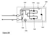
この背景に対して、電子モジュールのハウジング内に収容された複数の電子デバイスを冷却するためのシステムおよび方法が提供される。特に、システムは、各々がそれぞれの第1の液体冷却剤および第2の液体冷却剤を循環させる第1の冷却循環装置および第2の冷却循環装置、または第1の冷却ループおよび第2の冷却ループを備える。冷却循環システムの各々は、電子モジュール内の複数のデバイスの電子デバイスを冷却するために使用される。一方、第2の冷却循環装置は、熱交換器を介して第1の液体冷却剤と第2の液体冷却剤との間で熱交換することによって、第1の冷却循環システム内を循環する冷却剤を冷却するようにさらに構成される。第1の冷却循環装置および第2の冷却循環装置は、異なる効率を有することができ、したがって、第2の冷却循環装置によって提供されるより効率的な冷却を使用して、第1の液体冷却剤を冷却することができる。さらに、より効率的な第2の冷却循環装置は、(比較的多くの熱を生成する)特定の高出力電子デバイスに集中することができる。第1の液体冷却剤は、電子モジュール内の環境全体のために概してより低い温度を維持するために使用することができる。 SUMMARY OF THE DISCLOSURE Against this background, a system and method are provided for cooling a plurality of electronic devices contained within a housing of an electronic module. In particular, the system comprises a first cooling circulation device and a second cooling circulation device, or a first cooling loop and a second cooling loop, each of which circulates a respective first liquid coolant and a second liquid coolant. Each of the cooling circulation systems is used to cool the electronic devices of the plurality of devices within the electronic module. Meanwhile, the second cooling circulation device is further configured to cool the coolant circulating within the first cooling circulation system by exchanging heat between the first liquid coolant and the second liquid coolant via a heat exchanger. The first cooling circulation device and the second cooling circulation device may have different efficiencies, and thus the more efficient cooling provided by the second cooling circulation device may be used to cool the first liquid coolant. Furthermore, the more efficient second cooling circulation device may be focused on certain high-power electronic devices (which generate relatively more heat). The first liquid coolant may be used to maintain a generally lower temperature for the entire environment within the electronic module.
好ましい例では、第2の冷却循環装置は、複数の電子デバイスのうちの特定の電子デバイスに熱的に結合することができるコールドプレートを備えることができる。比較すると、第1の冷却循環システムは、電子モジュール内のリザーバに部分的に収容された第1の液体冷却剤を循環させることができ、いくつかの電子デバイスは、第1の液体冷却剤のリザーバに少なくとも部分的に浸漬される。さらに、第1の冷却循環システム内に堰または浴槽のヒートシンクを含めることによって、後述するように、記載されているシステムおよび方法にさらなる利点を提供することができる。In a preferred example, the second cooling circulation apparatus may comprise a cold plate that may be thermally coupled to a particular electronic device of the plurality of electronic devices. In comparison, the first cooling circulation system may circulate a first liquid coolant partially contained in a reservoir within the electronic module, with some electronic devices being at least partially immersed in the reservoir of the first liquid coolant. Additionally, the inclusion of a weir or bath heat sink within the first cooling circulation system may provide further advantages to the described systems and methods, as described below.
第1の態様では、電子モジュールのハウジング内に収容された複数の電子デバイスを冷却するためのシステムであって、
複数の電子デバイスのうちの第1の電子デバイスと熱交換器との間で第1の液体冷却剤を循環させるように構成された第1の冷却循環装置であって、第1の電子デバイスは、熱が第1の電子デバイスから第1の液体冷却剤に伝達されるように第1の液体冷却剤に熱的に結合されている、第1の冷却循環装置と、
複数の電子デバイスのうちの第2の電子デバイスと熱交換器との間で第2の液体冷却剤を循環させるように構成された第2の冷却循環装置であって、第2の電子デバイスは、熱が第2の電子デバイスから第2の液体冷却剤に伝達されるように第2の液体冷却剤に熱的に結合されている、第2の冷却循環装置と
を備え、
第1の冷却循環装置および第2の冷却循環装置は、熱が熱交換器を介して第1の液体冷却剤から第2の液体冷却剤に伝達されるように、少なくとも熱交換器を介して熱的に結合されている、システムが説明される。 In a first aspect, a system for cooling a plurality of electronic devices contained within an electronic module housing includes:
a first cooling circulation apparatus configured to circulate a first liquid coolant between a first electronic device of the plurality of electronic devices and a heat exchanger, the first electronic device being thermally coupled to the first liquid coolant such that heat is transferred from the first electronic device to the first liquid coolant;
a second cooling circulation apparatus configured to circulate a second liquid coolant between a second electronic device of the plurality of electronic devices and a heat exchanger, the second electronic device being thermally coupled to the second liquid coolant such that heat is transferred from the second electronic device to the second liquid coolant;
A system is described in which the first cooling circulation device and the second cooling circulation device are thermally coupled via at least a heat exchanger such that heat is transferred from the first liquid coolant to the second liquid coolant via the heat exchanger.
電子デバイスは、中央処理装置(CPU)、特定用途向け集積回路(ASIC)、グラフィックス処理装置(GPU)、ランダムアクセスメモリ(RAM)などを含む集積回路(IC)を含む任意の発熱デバイスまたは構成要素であってもよい。デバイスはともに接続されて、サーバもしくは他のコンピュータ処理機能、または他のITを形成してもよい。An electronic device may be any heat-generating device or component, including integrated circuits (ICs) including central processing units (CPUs), application specific integrated circuits (ASICs), graphics processing units (GPUs), random access memories (RAMs), etc. Devices may be connected together to form a server or other computer processing functionality, or other IT.
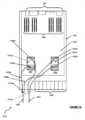
電子モジュールまたはサーバモジュールは、コンピュータサーバの一部を形成するモジュールであってもよい。電子モジュールは、電子デバイスの各々が搭載されるシャーシまたはハウジングを有してもよい。電子モジュールは、ラック内に搭載または設置するように構成されてもよい。例えば、電子モジュールは、標準的なサーバラック(1RU(1ラックユニット)または1OU(1オープンユニット)として知られている)に適合するために必要な業界標準寸法に準拠することができる。このようなユニットは、ブレードサーバと呼ばれることがある。The electronics module or server module may be a module that forms part of a computer server. The electronics module may have a chassis or housing in which each of the electronic devices is mounted. The electronics module may be configured to be mounted or installed in a rack. For example, the electronics module may conform to industry standard dimensions required to fit into a standard server rack (known as 1RU (one rack unit) or 1OU (one open unit)). Such a unit may be referred to as a blade server.
システムは、第1の冷却循環装置および第2の冷却循環装置(または第1の冷却ループおよび第2の冷却ループ)を備える。冷却循環装置は、電子モジュールを通るそれぞれの第1の冷却剤および第2の冷却剤の流れのための構成を提供する。The system includes a first cooling circulation device and a second cooling circulation device (or a first cooling loop and a second cooling loop). The cooling circulation devices provide an arrangement for the flow of the respective first and second coolants through the electronic module.
具体的には、第1の冷却循環装置は、少なくとも第1の電子発熱デバイス(第1の液体冷却剤によって当該デバイスから熱が吸収される)から熱交換器へと第1の液体冷却剤を循環させるかまたは流す。熱交換器において第1の液体冷却剤から熱を除去することができる。Specifically, the first cooling circulation system circulates or channels a first liquid coolant from at least a first electronic heat generating device (from which heat is absorbed by the first liquid coolant) to a heat exchanger, where heat can be removed from the first liquid coolant.
第2の冷却循環装置は、少なくとも第2の電子発熱デバイス(第2の液体冷却剤によって当該デバイスから熱が吸収される)から熱交換器へと第2の液体冷却剤を循環させるかまたは流す。熱交換器において、第1の液体冷却剤からの熱は、第2の液体冷却剤によって受け取られる。The second cooling circulation system circulates or flows the second liquid coolant from at least a second electronic heat generating device (where heat is absorbed by the second liquid coolant) to a heat exchanger, where heat from the first liquid coolant is received by the second liquid coolant.
場合によっては、第2の冷却循環装置を閉じてもよい(換言すれば、液体冷却剤は、ループ内で再循環およびリサイクルされる)が、これは常にそうであるとは限らない。代替的な場合には、第2の冷却循環装置は、液体冷却剤が受け入れられ、既述の経路の周りを流れ、次いで排液系に送られる開ループを表すことができる。例えば、熱交換器を通過した後、第2の冷却循環装置内の第2の液体冷却剤は、(電子モジュールに戻る前に冷却システムを通過することによって)冷却されるか、または補充される(例えば、第2の液体冷却剤が、施設給水設備などの施設規模の冷却剤供給設備の一部である場合)。In some cases, the second cooling circuit may be closed (in other words, the liquid coolant is recirculated and recycled within the loop), but this is not always the case. In alternative cases, the second cooling circuit may represent an open loop in which the liquid coolant is received, flows around the path already described, and then sent to a drainage system. For example, after passing through the heat exchanger, the second liquid coolant in the second cooling circuit may be cooled (by passing through a cooling system before returning to the electronics module) or replenished (e.g., if the second liquid coolant is part of a facility-wide coolant supply, such as a facility water supply).
有益なことに、既述のシステムは、2つの冷却循環装置のハイブリッドシステムである。そのようなハイブリッドシステムを使用することにより、特に高温の構成要素(少なくとも第2の電子デバイスを対象とする第2の冷却循環装置)を対象とする、より高性能でより効率的な冷却構成、ならびに他のデバイスを冷却するためのさらなる冷却構成の使用が可能になる。しかしながら、単純に2つの完全に別個の冷却システムを並列に使用するよりも、本発明者らは、より高性能の冷却装置の戻り流を使用して、他方のより性能の低い冷却装置から熱を除去することもできることを認識した。ある程度まで、第1の冷却循環装置は、第2の冷却循環装置と入れ子になっていると考えることができる。Advantageously, the system described is a hybrid system of two cooling circuits. The use of such a hybrid system allows for a higher performance and more efficient cooling configuration, particularly for the hot components (the second cooling circuit for at least the second electronic device), as well as the use of further cooling configurations for cooling other devices. However, rather than simply using two completely separate cooling systems in parallel, the inventors have recognized that the return flow of the higher performance cooling circuit can also be used to remove heat from the other, less powerful cooling circuit. To some extent, the first cooling circuit can be considered nested with the second cooling circuit.
任意選択的に、第1の液体冷却剤は誘電性液体であり、第2の液体冷却剤は水である。本明細書では液体冷却剤という用語が使用されているが、任意の適切な流体冷却剤が使用されてもよいことが理解されよう。Optionally, the first liquid coolant is a dielectric liquid and the second liquid coolant is water. Although the term liquid coolant is used herein, it will be understood that any suitable fluid coolant may be used.
任意選択的に、第2の冷却循環装置は冷却システムをさらに備え、第2の冷却循環装置は、複数の電子デバイスのうちの第2の電子デバイス、熱交換器、および冷却システムの間で第2の液体冷却剤を循環させるように構成され、熱が、冷却システムによって第2の液体冷却剤から除去される。好ましくは、冷却システムは、電子モジュールの外部にあるように配置される。言い換えれば、第2の冷却循環装置は閉ループを形成し、電子モジュールから受け取った第2の液体冷却剤は、第2の電子デバイスを冷却するために電子モジュールに戻される前に、冷却システムによって冷却される。Optionally, the second cooling circulation device further comprises a cooling system, the second cooling circulation device configured to circulate a second liquid coolant between a second electronic device of the plurality of electronic devices, the heat exchanger, and the cooling system, and heat is removed from the second liquid coolant by the cooling system. Preferably, the cooling system is arranged to be external to the electronic module. In other words, the second cooling circulation device forms a closed loop, and the second liquid coolant received from the electronic module is cooled by the cooling system before being returned to the electronic module for cooling the second electronic device.
あるいは、第2の冷却循環装置は、第2の液体冷却剤供給設備に接続され、第2の冷却循環装置は、第2の液体冷却剤供給設備から受け取った第2の液体冷却剤を複数の電子デバイスのうちの第2の電子デバイスと熱交換器との間で循環させ、第2の液体冷却剤供給設備に戻すように構成される。言い換えれば、第2の冷却循環装置は開ループであり、第2の液体冷却剤は、施設レベルの供給設備から供給され、絶えず補充される。例えば、第2の液体冷却剤供給設備は給水設備であってもよく、そこから水が(第2の液体冷却剤として)受け取られ、第2の冷却循環装置を通って循環され、次いで第2の冷却循環装置を施設排水路へと出ることができる。Alternatively, the second cooling circulation device is connected to a second liquid coolant supply facility, and the second cooling circulation device is configured to circulate the second liquid coolant received from the second liquid coolant supply facility between a second electronic device of the plurality of electronic devices and the heat exchanger and return it to the second liquid coolant supply facility. In other words, the second cooling circulation device is open loop, and the second liquid coolant is supplied from a facility-level supply facility and is constantly replenished. For example, the second liquid coolant supply facility may be a water facility, from which water is received (as the second liquid coolant), circulated through the second cooling circulation device, and then exits the second cooling circulation device to a facility drain.
好ましくは、熱交換器は、熱界面によって分離された少なくとも第1のチャンバおよび第2のチャンバを備え、熱交換器は、熱が熱界面を通じて第1の液体冷却剤から第2の液体冷却剤に伝達されるように、少なくとも第1のチャンバを通る第1の液体冷却剤の流れ、および少なくとも第2のチャンバを通る第2の液体冷却剤の流れのために構成される。熱交換器は、第1の液体冷却剤および第2の液体冷却剤の間で熱を交換するように構成された専用の要素である。第1の液体冷却剤および第2の液体冷却剤の各々は、熱交換器の1つまたは複数の専用のチャンバを通過することができ、熱は、チャンバ間の熱界面を介して第1の液体冷却剤から第2の液体冷却剤に通過することができる。熱交換器は、任意の適切な設計であってもよく、熱交換の効率を改善するために、複数のチャンバおよび複数の熱界面を提供することができる。熱界面の表面積を増加させ、第1の液体冷却剤と第2の液体冷却剤との間の熱交換の効率を促進するために、熱界面にフィンまたは他の突出物を設けることができる。任意選択的に、熱交換器はプレート熱交換器である。Preferably, the heat exchanger comprises at least a first chamber and a second chamber separated by a thermal interface, the heat exchanger being configured for flow of the first liquid coolant through at least the first chamber and for flow of the second liquid coolant through at least the second chamber, such that heat is transferred from the first liquid coolant to the second liquid coolant through the thermal interface. The heat exchanger is a dedicated element configured to exchange heat between the first liquid coolant and the second liquid coolant. Each of the first liquid coolant and the second liquid coolant can pass through one or more dedicated chambers of the heat exchanger, and heat can pass from the first liquid coolant to the second liquid coolant through the thermal interface between the chambers. The heat exchanger may be of any suitable design and may provide multiple chambers and multiple thermal interfaces to improve the efficiency of the heat exchange. The thermal interfaces may be provided with fins or other protrusions to increase the surface area of the thermal interfaces and promote the efficiency of the heat exchange between the first liquid coolant and the second liquid coolant. Optionally, the heat exchanger is a plate heat exchanger.
好ましくは、熱交換器は、電子モジュールのハウジング内に配置される。特に、熱交換器は、電子モジュール内に収容される。これにより、少なくとも第1の液体冷却剤を電子モジュール内に完全に保持することができる。これにより、電子モジュールへの接続および電子モジュールからの接続の複雑さが低減される。これはまた、電子モジュールを密閉モジュールとして提供することを可能にし、これは、第2の液体冷却剤が誘電体である場合に有利であり得、モジュールから放出されると人間に有害であり得、漏れまたは紛失の場合に交換するのに費用がかかる可能性がある。Preferably, the heat exchanger is arranged within the housing of the electronic module. In particular, the heat exchanger is housed within the electronic module. This allows at least the first liquid coolant to be kept entirely within the electronic module. This reduces the complexity of the connections to and from the electronic module. This also allows the electronic module to be provided as a sealed module, which may be advantageous if the second liquid coolant is a dielectric, which may be harmful to humans if released from the module and may be expensive to replace in case of leakage or loss.
任意選択的に、第1の冷却循環装置は、電子モジュールのハウジング内に完全に収容される。言い換えれば、第1の冷却循環装置は、通常動作時に第1の液体冷却剤が電子モジュールのハウジングの範囲から出ないように配置される。Optionally, the first cooling circulation device is entirely contained within the housing of the electronic module. In other words, the first cooling circulation device is positioned such that the first liquid coolant does not leave the confines of the housing of the electronic module during normal operation.
第1の冷却循環装置は、第2の液体冷却剤が最も低温である、第2の冷却冷却剤が第2の電子デバイスに循環する前の第2の冷却循環装置の部分において、第2の冷却循環装置から少なくとも部分的に断熱することができる。第1の冷却循環装置は、第1の冷却循環装置および第2の冷却循環装置が熱的に結合される熱交換器を除いて、第2の冷却循環装置から少なくとも部分的に断熱することができる。言い換えれば、第2の冷却循環装置の(言い換えると、第2の電子デバイスから熱を受け取った後の)戻り流は、第1の液体冷却剤を冷却するために使用される。これは、第2の電子デバイスにおける冷却能(またはより具体的には、温度勾配)を最大化するために、第2の電子デバイスに到達する前に第2の液体冷却剤の温度を上昇させることを回避する。The first cooling circulation device can be at least partially insulated from the second cooling circulation device in the portion of the second cooling circulation device before the second liquid coolant is circulated to the second electronic device, where the second liquid coolant is at its coldest. The first cooling circulation device can be at least partially insulated from the second cooling circulation device, except for the heat exchanger to which the first cooling circulation device and the second cooling circulation device are thermally coupled. In other words, the return flow of the second cooling circulation device (in other words, after receiving heat from the second electronic device) is used to cool the first liquid coolant. This avoids increasing the temperature of the second liquid coolant before it reaches the second electronic device in order to maximize the cooling capacity (or more specifically, the temperature gradient) at the second electronic device.
任意選択的に、電子モジュールのハウジングは、第1の液体冷却剤を収容し、第1の電子デバイスは、第1の液体冷却剤に少なくとも部分的に浸漬される。言い換えれば、第1の冷却循環装置は、浸漬冷却装置である。熱は、第1の液体冷却剤に少なくとも部分的に浸漬されている第1の電子デバイスの表面から第1の液体冷却剤に直接伝達することができる。第2の電子デバイスを含む第2の冷却循環装置の部分もまた、第1の液体冷却剤に少なくとも部分的に浸漬されてもよい。Optionally, the housing of the electronic module contains a first liquid coolant and the first electronic device is at least partially immersed in the first liquid coolant. In other words, the first cooling circulation apparatus is an immersion cooling apparatus. Heat can be transferred directly to the first liquid coolant from a surface of the first electronic device that is at least partially immersed in the first liquid coolant. The portion of the second cooling circulation apparatus that includes the second electronic device may also be at least partially immersed in the first liquid coolant.
対照的に、第2の冷却循環装置は、冷却モジュールおよび熱交換器を通じて第2の液体冷却剤を循環させるように構成することができ、冷却モジュールは、冷却モジュールの搭載面において第2の電子デバイスに搭載される。このため、第2の冷却モジュールの搭載面を介して、第2の電子デバイスと第2の液体冷却剤との間で間接的に熱が交換される。第2の冷却循環装置の一部を形成する冷却モジュールについては、下記により詳細に説明する。In contrast, the second cooling circulation apparatus may be configured to circulate the second liquid coolant through a cooling module and a heat exchanger, the cooling module being mounted to the second electronic device at a mounting surface of the cooling module. Thus, heat is exchanged indirectly between the second electronic device and the second liquid coolant via the mounting surface of the second cooling module. The cooling module forming part of the second cooling circulation apparatus is described in more detail below.
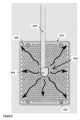
好ましい例では、第1の冷却循環装置は堰を備え、堰は、
基部および基部から延在する保持壁であって、基部および保持壁は、第1の液体冷却剤の一部を維持するための容積を画定する、基部および保持壁と、
第1の液体冷却剤が容積に流入する入口と
を備え、
入口を通って容積内に十分な第1の液体冷却剤が流れることにより、第1の液体冷却剤が保持壁から溢れ出て、電子モジュールのハウジング内に収容されており、かつ堰の外部にある第1の液体冷却剤と合流する。 In a preferred embodiment, the first cooling circuit comprises a weir, the weir comprising:
a base and a retaining wall extending from the base, the base and the retaining wall defining a volume for retaining a portion of the first liquid coolant;
an inlet through which a first liquid coolant flows into the volume;
Flow of sufficient first liquid coolant through the inlet and into the volume causes the first liquid coolant to overflow the retaining wall and merge with the first liquid coolant contained within the housing of the electronic module and external to the weir.
基部および保持壁は、第1の冷却剤がそこから溢れ出ることができる容器または「浴槽」を提供することができる。堰は、第1の電子デバイスのヒートシンクとして機能するために、第1の電子デバイスの表面に結合することができる。したがって、堰は、液体冷却剤を発熱電子デバイスに対して維持または保持するための容積を提供する。代替的または付加的に、堰は、電子デバイス内の他の構成要素と比較して、および/または電子モジュールのハウジングのキャビティ内の第1の冷却剤の液位と比較して上昇したPCB上に搭載されてもよい。このようにして、第1の液体冷却剤は、堰から溢れ出ると、第1の電子デバイスおよび電子モジュール内に収容されたいくつかの他の電子デバイスまたは構成要素の上を流れるように作用する。The base and retaining wall can provide a container or "bath" from which the first coolant can overflow. The weir can be coupled to a surface of the first electronic device to act as a heat sink for the first electronic device. The weir thus provides a volume for maintaining or holding the liquid coolant against the heat-generating electronic device. Alternatively or additionally, the weir may be mounted on the PCB elevated relative to other components in the electronic device and/or relative to the level of the first coolant in the cavity of the housing of the electronic module. In this way, the first liquid coolant, upon overflowing the weir, acts to flow over the first electronic device and any other electronic devices or components housed within the electronic module.
堰は、第1の冷却循環装置を通って循環する第1の液体冷却剤の流れを導くように構成することができる。言い換えれば、堰は、堰から溢れ出る第1の液体冷却剤が電子モジュール内に収容された特定の電子デバイスの上へとまたはその上で流れるように構成することができる。有利には、堰を第1の冷却循環装置に含めることによって、液体冷却剤を、最も熱が発生する1つまたは複数の場所により効果的に適用することができる。したがって、より少ない冷却剤を使用することができる。冷却剤は高価で重いため、冷却剤の量を減らすことにより、可撓性、効率および信頼性を向上させることができる(例えば、冷却剤の漏れが起こりにくく、容積中の冷却剤が、システム内の他の構成要素の障害によって引き起こされる瞬間的な温度変化に耐えることができるため、)。The weir can be configured to direct the flow of the first liquid coolant circulating through the first cooling circulation apparatus. In other words, the weir can be configured to allow the first liquid coolant overflowing the weir to flow to or over the particular electronic device contained within the electronic module. Advantageously, by including the weir in the first cooling circulation apparatus, the liquid coolant can be more effectively applied to the location or locations where the most heat is generated. Thus, less coolant can be used. Because coolant is expensive and heavy, reducing the amount of coolant can improve flexibility, efficiency, and reliability (e.g., because coolant leaks are less likely to occur and the volume of coolant can withstand momentary temperature changes caused by the failure of other components in the system).
堰に関して、第1の液体冷却剤を維持または保持するための容積は、基部および保持壁(一体であってもよく、または分離していてもよい)によって画定することができる。基部は、電子デバイス(より具体的には、電子デバイスの伝熱面)の上部に搭載することができ、伝熱面から熱を伝達する堰の部分である。基部は、典型的には、容積を画定する平坦面を有する(また、基部自体が平坦な形状であってもよい)。基部(特に、容積を画定するその表面)を通って伝達される(典型的には伝導された)熱は、容積内に維持された液体冷却剤に伝達される。保持壁は、基部から延在する。With respect to the weir, a volume for maintaining or retaining a first liquid coolant can be defined by a base and a retaining wall (which may be integral or separate). The base is the portion of the weir that can be mounted on top of an electronic device (more specifically, a heat transfer surface of the electronic device) and transfers heat from the heat transfer surface. The base typically has a planar surface that defines the volume (and the base itself may be of planar shape). Heat transferred (typically conducted) through the base (particularly its surface that defines the volume) is transferred to the liquid coolant maintained within the volume. The retaining wall extends from the base.
堰の1つの効果は、堰の容積内に維持された冷却剤の液位をその容積の外部よりも高くし(少なくとも冷却モジュールが電子デバイスおよび/または回路基板の平面を水平にして動作する場合)、冷却モジュールの容器内の冷却剤の量を保持壁の高さよりも低くすることである。One effect of the weir is to maintain the level of coolant maintained within the weir volume higher than outside that volume (at least when the cooling module is operated with the plane of the electronic device and/or circuit board horizontal) and to reduce the amount of coolant within the cooling module's container below the height of the retaining wall.
有利には、ヒートシンクは、容積内で基部(またはあまり好ましくないが、保持壁から)から延在する突出部(ピンおよび/またはフィンなど)を有する。突出部は、液体冷却剤を基部の表面上の所定の点から外方に(例えば、電子デバイスの最も高温の部分と一致して)半径方向に広げることができる。特に、突出部は、非線形パターンに形成することができる。Advantageously, the heat sink has protrusions (such as pins and/or fins) extending from the base (or, less preferably, from the retaining wall) within the volume. The protrusions can spread the liquid coolant radially outwardly (e.g., coincident with the hottest portion of the electronic device) from a predetermined point on the surface of the base. In particular, the protrusions can be formed in a non-linear pattern.
好ましくは、堰への入口は、容積内に流入する第1の液体冷却剤を導くためのノズル装置をさらに備える。ノズル装置は、1つまたは複数のノズル(押し込み式であってもよい)を備えることができ、その各々は、流れるまたは圧送される第1の液体冷却剤を堰の容積のそれぞれの部分、特に堰の基部の一部に導く。1つまたは複数のノズルは各々、基部の中、保持壁の中、または容積の上部の上に配置されて、第1の液体冷却剤を容積に流入させることができる。例えば、各ノズルは、最大温度または閾値レベルを超える温度を有する電子デバイスの伝熱面の一部(すなわち、デバイスの最も高温な部分の1つ)に隣接する堰の容積のそれぞれの部分に、流れるまたは圧送される液体冷却剤を導くことができる。最も好ましくは、ノズル装置は、流れるまたは圧送される液体冷却剤を堰の基部に垂直な方向に導く。これにより、冷却剤を容積内に直接押し込むことができ、熱放散を改善することができる。Preferably, the inlet to the weir further comprises a nozzle arrangement for directing the first liquid coolant flowing into the volume. The nozzle arrangement may comprise one or more nozzles (which may be push-in type), each of which directs the flowing or pumped first liquid coolant into a respective portion of the weir volume, in particular a portion of the base of the weir. The one or more nozzles may each be positioned in the base, in the retaining wall, or on the top of the volume to direct the first liquid coolant into the volume. For example, each nozzle may direct the flowing or pumped liquid coolant into a respective portion of the weir volume adjacent to a portion of the heat transfer surface of the electronic device having a maximum temperature or a temperature above a threshold level (i.e., one of the hottest portions of the device). Most preferably, the nozzle arrangement directs the flowing or pumped liquid coolant in a direction perpendicular to the base of the weir. This allows the coolant to be directly pushed into the volume, improving heat dissipation.
好ましくは、第1の冷却循環装置は、第1の冷却循環装置を巡って第1の液体冷却剤を循環させるように構成されたポンプをさらに備える。ポンプは、電子モジュール内に収容された液体冷却剤のリザーバから第1の液体冷却剤を受け取るように構成することができ、少なくとも第1の電子デバイスは、少なくとも部分的に浸漬される。次いで、ポンプは、受け取った第1の液体冷却剤を電子モジュールの別の領域、例えば熱交換器に移動させ、次いで堰の入口に移動させることができる。ポンプは、第1の液体冷却剤に少なくとも部分的に浸漬することができ、それによって第1の液体冷却剤はポンプの冷却も支援する。Preferably, the first cooling circulation apparatus further comprises a pump configured to circulate the first liquid coolant around the first cooling circulation apparatus. The pump may be configured to receive the first liquid coolant from a reservoir of liquid coolant contained within the electronic module, with at least the first electronic device being at least partially submerged. The pump may then move the received first liquid coolant to another region of the electronic module, for example a heat exchanger, and then to the inlet of the weir. The pump may be at least partially submerged in the first liquid coolant, whereby the first liquid coolant also assists in cooling the pump.
第1の冷却循環装置は、電子モジュールのハウジング内に収容され且つ堰の外側にある第1の液体冷却剤を受け入れるように配置されたポンプ入口をさらに備えることができる。言い換えれば、電子モジュール内に収容された第1の液体冷却剤は、ポンプ入口によって受け入れられ、ポンプに送ることができる。The first cooling circulation device may further comprise a pump inlet arranged to receive a first liquid coolant contained within the housing of the electronic module and outside the weir. In other words, the first liquid coolant contained within the electronic module may be received by the pump inlet and delivered to the pump.
好ましくは、第1の冷却循環装置は、第1の液体冷却剤をポンプから熱交換器に、熱交換器から堰の入口にそれぞれ輸送するように構成された少なくとも第1のパイプおよび第2のパイプをさらに備える。Preferably, the first cooling circulation device further comprises at least a first pipe and a second pipe configured to transport the first liquid coolant from the pump to the heat exchanger and from the heat exchanger to the inlet of the weir, respectively.
好ましくは、第2の冷却循環装置は、第2の電子デバイスを第2の液体冷却剤に熱的に結合するように構成された冷却モジュールをさらに備える。冷却モジュールは、第2の電子デバイスから第2の液体冷却剤への効率的な熱伝達のための特定の構成要素であり得る。冷却モジュールは、冷却モジュールの搭載面を介して第2の電子デバイスに搭載することができ、その結果、熱は、第2の電子デバイスから搭載面を通じて第2の液体冷却剤に伝達される。Preferably, the second cooling circulation device further comprises a cooling module configured to thermally couple the second electronic device to the second liquid coolant. The cooling module may be a specific component for efficient heat transfer from the second electronic device to the second liquid coolant. The cooling module may be mounted on the second electronic device via a mounting surface of the cooling module, such that heat is transferred from the second electronic device through the mounting surface to the second liquid coolant.
好ましくは、冷却モジュールはコールドプレートを備え、コールドプレートは、
コールドプレートハウジングであって、コールドプレートハウジングの表面が、コールドプレートハウジングに熱的に結合された第2の電子デバイスを冷却するための熱界面を提供するように構成されている、コールドプレートハウジングと、
コールドプレートハウジング内の、コールドプレートハウジングの表面に近接した少なくとも1つのチャネルであって、少なくとも1つのチャネルは、第2の電子デバイスからコールドプレートハウジングの表面を通じて受け取られる熱が第2の液体冷却剤に伝達されるように、第2の液体冷却剤がチャネルを通って流れるように構成されている、少なくとも1つのチャネルと
を備える。 Preferably, the cooling module comprises a cold plate, the cold plate comprising:
a cold plate housing, a surface of the cold plate housing configured to provide a thermal interface for cooling a second electronic device thermally coupled to the cold plate housing;
at least one channel within the cold plate housing proximate a surface of the cold plate housing, the at least one channel configured to allow a second liquid coolant to flow therethrough such that heat received through the surface of the cold plate housing from the second electronic device is transferred to the second liquid coolant.
有利には、コールドプレートは、電子モジュール内の特定の電子デバイスを冷却するための効率的かつ効果的な機構を提供する。コールドプレートは、それが熱的に結合されている第2の電子デバイスに高性能冷却を提供する。したがって、電子モジュール内の1つまたは複数の最も高温の構成要素にコールドプレートを結合して、これらの構成要素に最大の冷却能を提供することができる。Advantageously, the cold plate provides an efficient and effective mechanism for cooling a particular electronic device within an electronic module. The cold plate provides high performance cooling to a second electronic device to which it is thermally coupled. Thus, the cold plate can be coupled to one or more of the hottest components within an electronic module to provide maximum cooling capacity to those components.
任意選択的に、コールドプレートハウジングの表面は、第2の電子デバイスの表面に直接結合されてもよい。あるいは、ハウジングは、さらなる界面または構成要素によって結合されてもよい。それにもかかわらず、コールドプレートおよび第2の電子デバイスは、第2の電子デバイスから第2の液体冷却剤への効果的かつ効率的な熱伝達を促進するために熱的に結合される。Optionally, a surface of the cold plate housing may be directly coupled to a surface of the second electronic device. Alternatively, the housing may be coupled by additional interfaces or components. Nevertheless, the cold plate and the second electronic device are thermally coupled to facilitate effective and efficient heat transfer from the second electronic device to the second liquid coolant.
第2の冷却循環装置の一部として、2つ以上のコールドプレートを電子モジュール内に配置することができる。2つ以上のコールドプレートを第2の冷却循環装置内に並列または直列に配置することができ、または3つ以上のコールドプレートが使用される場合、並列構成と直列構成との組み合わせを実施することができる。Two or more cold plates can be arranged in the electronics module as part of the second cooling circulation system. Two or more cold plates can be arranged in parallel or series in the second cooling circulation system, or a combination of parallel and series configurations can be implemented if more than two cold plates are used.
好ましくは、第2の冷却循環装置は、コールドプレートと熱交換器との間で第2の液体冷却剤を輸送するとともに、電子モジュールの外部にある任意の冷却システムまたは冷却剤供給設備に接続するように構成された複数の導管を備える。Preferably, the second cooling circulation device comprises a plurality of conduits configured to transport a second liquid coolant between the cold plate and the heat exchanger and to connect to any cooling system or coolant supply facility external to the electronic module.
第2の態様では、電子モジュールのハウジング内に収容された複数の電子デバイスを冷却するための方法であって、
第1の冷却循環装置を巡って第1の液体冷却剤を循環させるステップであって、複数の電子デバイスのうちの第1の電子デバイスと熱交換器との間で第1の液体冷却剤を循環させることを含み、第1の電子デバイスは、熱が第1の電子デバイスから第1の液体冷却剤に伝達されるように第1の液体冷却剤に熱的に結合されている、第1の液体冷却剤を循環させるステップと、
第2の冷却循環装置を巡って第2の液体冷却剤を循環させるステップであって、複数の電子デバイスのうちの第2の電子デバイスと熱交換器との間で第2の液体冷却剤を循環させることを含み、第2の電子デバイスは、熱が第2の電子デバイスから第2の液体冷却剤に伝達されるように第2の液体冷却剤に熱的に結合されている、第2の液体冷却剤を循環させるステップと
を含み、
第1の冷却循環装置および第2の冷却循環装置は、熱が熱交換器を介して第1の液体冷却剤から第2の液体冷却剤に伝達されるように、少なくとも熱交換器を介して熱的に結合されている、方法が説明される。 In a second aspect, a method for cooling a plurality of electronic devices contained within a housing of an electronic module, comprising:
circulating a first liquid coolant around a first cooling circulation apparatus, the first liquid coolant including circulating the first liquid coolant between a first electronic device of the plurality of electronic devices and a heat exchanger, the first electronic device being thermally coupled to the first liquid coolant such that heat is transferred from the first electronic device to the first liquid coolant;
circulating a second liquid coolant around a second cooling circulation apparatus, the second liquid coolant including circulating the second liquid coolant between a second electronic device of the plurality of electronic devices and a heat exchanger, the second electronic device being thermally coupled to the second liquid coolant such that heat is transferred from the second electronic device to the second liquid coolant;
A method is described in which the first cooling circulation device and the second cooling circulation device are thermally coupled via at least a heat exchanger such that heat is transferred from the first liquid coolant to the second liquid coolant via the heat exchanger.
言い換えれば、本方法は、第1の冷却循環装置を巡って第1の液体冷却剤を循環させるステップと、第2の冷却循環装置を巡って第2の液体冷却剤を循環させるステップとを含むことができる。第1の冷却循環装置および第2の冷却循環装置の各々は、少なくともそれぞれの第1の電子デバイスおよび第2の電子デバイスを冷却するように構成される。さらに、第2の冷却循環装置は、第2の液体冷却剤が熱交換器において第1の液体冷却剤から伝達される熱を受け取るように構成される。有利には、このハイブリッド冷却システムは、最も高温の構成要素(第1の電子デバイスを標的とする第2の冷却循環装置)に関して高性能冷却システムの利点を提供するが、その後、電子モジュール内の他の構成要素を冷却するためのさらなる冷却システムを使用する。特に、電子モジュール内のすべての構成要素に目標とする冷却システム(第2の冷却循環装置によって提供されるものなど)を搭載することは実際的ではない場合があり、したがって、第1の冷却循環装置は、残りの構成要素に追加の冷却システムを提供し、電子モジュール内の全般的な環境の温度を低下させることができる。さらに、高性能の第2の冷却循環装置の戻り流自体を利用して、第1の冷却システムから熱を除去することもできる。In other words, the method can include circulating a first liquid coolant through a first cooling circulation device and circulating a second liquid coolant through a second cooling circulation device. Each of the first and second cooling circulation devices is configured to cool at least the respective first and second electronic devices. Furthermore, the second cooling circulation device is configured such that the second liquid coolant receives heat transferred from the first liquid coolant in a heat exchanger. Advantageously, this hybrid cooling system provides the benefits of a high-performance cooling system for the hottest component (the second cooling circulation device targeting the first electronic device), but then uses an additional cooling system to cool other components in the electronic module. In particular, it may be impractical to equip all components in the electronic module with a targeted cooling system (such as that provided by the second cooling circulation device), and therefore the first cooling circulation device can provide an additional cooling system for the remaining components to reduce the temperature of the general environment in the electronic module. Additionally, the return flow of the high-performance second cooling circuit can itself be used to remove heat from the first cooling system.
システムに関して上述した特徴は、電子モジュールのハウジングに収容された複数の電子デバイスを冷却するための方法の使用においても開示されると考えることができることが理解されよう。It will be appreciated that the features described above with respect to the system may also be considered to be disclosed in the use of a method for cooling a plurality of electronic devices contained in a housing of an electronic module.
特に、好ましくは、第2の冷却循環装置は冷却システムをさらに備え、第2の冷却循環装置を巡って第2の液体冷却剤を循環させるステップは、複数の電子デバイスのうちの第2の電子デバイス、熱交換器、および冷却システムの間で第2の液体冷却剤を循環させることを含み、熱が、冷却システムによって第2の液体冷却剤から除去される。冷却システムは、電子モジュールの外部にあってもよく、第2の液体冷却剤から外方に熱を伝達するように構成されてもよい。例えば、冷却システムは、さらなる(第3の)冷却剤液体または媒体に熱を伝達するための熱交換器を備えることができる。In particular, preferably, the second cooling circulation device further comprises a cooling system, and the step of circulating the second liquid coolant around the second cooling circulation device comprises circulating the second liquid coolant between a second electronic device of the plurality of electronic devices, a heat exchanger, and the cooling system, and heat is removed from the second liquid coolant by the cooling system. The cooling system may be external to the electronic module and may be configured to transfer heat outwardly from the second liquid coolant. For example, the cooling system may comprise a heat exchanger for transferring heat to a further (third) coolant liquid or medium.
あるいは、第2の冷却循環装置は、第2の液体冷却剤供給設備をさらに備え、第2の冷却循環装置を巡って第2の液体冷却剤を循環させるステップは、第2の液体冷却剤供給設備から第2の液体冷却剤を受け取ることと、第2の液体冷却剤を複数の電子デバイスのうちの第2の電子デバイスと熱交換器との間で循環させて、次いで、第2の液体冷却剤供給設備に戻すこととを含む。例えば、第2の液体冷却剤は水であってもよく、第2の冷却循環装置は施設給水設備に接続されてもよい。水が第2の冷却循環装置を通って循環されると、それは排水システムに入ることができる(したがって、第2の冷却循環装置を通って再循環されない)。Alternatively, the second cooling circulation device further comprises a second liquid coolant supply facility, and the step of circulating the second liquid coolant around the second cooling circulation device includes receiving the second liquid coolant from the second liquid coolant supply facility, circulating the second liquid coolant between a second electronic device of the plurality of electronic devices and the heat exchanger, and then returning it to the second liquid coolant supply facility. For example, the second liquid coolant may be water, and the second cooling circulation device may be connected to a facility water supply. Once the water has been circulated through the second cooling circulation device, it may enter the drainage system (and thus not be recirculated through the second cooling circulation device).
熱交換器は、熱界面によって分離された少なくとも第1のチャンバおよび第2のチャンバを備えることができ、熱交換器は、熱が熱界面を通じて第1の液体冷却剤から第2の液体冷却剤に伝達されるように、少なくとも第1のチャンバを通る第1の液体冷却剤の流れ、および少なくとも第2のチャンバを通る第2の液体冷却剤の流れのために構成される。熱交換器は、第1の液体冷却剤および第2の液体冷却剤の間で効率的に熱を伝達するように構成された特定の要素である。熱交換器は、それを通る第1の液体冷却剤および第2の液体冷却剤の流れを可能にし、それらの間で熱を交換するための任意の適切な設計であってもよい。任意選択的に、熱交換器はプレート熱交換器である。The heat exchanger may comprise at least a first chamber and a second chamber separated by a thermal interface, the heat exchanger configured for flow of a first liquid coolant through at least the first chamber and a second liquid coolant through at least the second chamber such that heat is transferred from the first liquid coolant to the second liquid coolant through the thermal interface. A heat exchanger is a specific element configured to efficiently transfer heat between the first liquid coolant and the second liquid coolant. The heat exchanger may be of any suitable design for allowing flow of the first liquid coolant and the second liquid coolant therethrough and exchanging heat therebetween. Optionally, the heat exchanger is a plate heat exchanger.
好ましくは、熱交換器は、電子モジュールのハウジング内に配置されるか、またはその中に収容される。有益なことに、これは、第1の液体冷却剤が電子モジュールから出ることを回避する。これは、電子モジュールのハウジングにおける接続の複雑さを低減するとともに、第1の液体冷却剤の漏れまたは損失のリスクも低減する。Preferably, the heat exchanger is located or contained within the housing of the electronic module. Advantageously, this prevents the first liquid coolant from exiting the electronic module. This reduces the complexity of the connections in the housing of the electronic module and also reduces the risk of leakage or loss of the first liquid coolant.
好ましくは、第1の冷却循環装置および第2の冷却循環装置は、第2の冷却循環装置の戻り流において熱交換器を介して熱的に結合される。言い換えると、第1の冷却循環装置および第2の冷却循環装置は、(第2の冷却循環装置の始動時に最も低温の第2の液体冷却剤が見出されると考える場合)第2の電子デバイスから熱を受け取った後に第2の液体冷却剤が熱交換器を通過するように、熱交換器を介して熱的に結合される。第1の冷却循環装置は、熱交換器の前に、第2の冷却循環装置から少なくとも部分的に断熱することができる。これは、第2の液体冷却剤と第2の電子デバイスとの間に可能な限り最大の温度勾配を提供する。Preferably, the first cooling circulation device and the second cooling circulation device are thermally coupled via a heat exchanger in the return flow of the second cooling circulation device. In other words, the first cooling circulation device and the second cooling circulation device are thermally coupled via a heat exchanger such that the second liquid coolant passes through the heat exchanger after receiving heat from the second electronic device (considering that the coldest second liquid coolant is found at the start of the second cooling circulation device). The first cooling circulation device can be at least partially insulated from the second cooling circulation device before the heat exchanger. This provides the largest possible temperature gradient between the second liquid coolant and the second electronic device.
好ましくは、電子モジュールのハウジングは、第1の液体冷却剤を収容し、第1の電子デバイスは、第1の液体冷却剤に少なくとも部分的に浸漬される。言い換えれば、電子デバイスのハウジングは、少なくとも第1の電子デバイスが少なくとも部分的に浸漬される第1の液体冷却剤のリザーバを収容する。したがって、熱は、第1の液体冷却剤に少なくとも部分的に浸漬されている第1の電子デバイスの表面から第1の液体冷却剤に直接伝達される。Preferably, the housing of the electronic module contains a first liquid coolant and the first electronic device is at least partially immersed in the first liquid coolant. In other words, the housing of the electronic device contains a reservoir of the first liquid coolant in which the first electronic device is at least partially immersed. Thus, heat is transferred directly to the first liquid coolant from a surface of the first electronic device that is at least partially immersed in the first liquid coolant.
好ましくは、第1の冷却循環装置は堰を備えることができる。堰は、
基部および基部から延在する保持壁であって、基部および保持壁は、第1の液体冷却剤の一部を維持するための容積を画定する、基部および保持壁と、
第1の液体冷却剤が容積に流入する入口と
を備え、
入口を通って容積内に十分な第1の液体冷却剤が流れることにより、第1の液体冷却剤が保持壁から溢れ出て、電子モジュールのハウジング内に収容されており、かつ堰の外部にある第1の液体冷却剤と合流する。 Preferably, the first cooling circuit device comprises a weir.
a base and a retaining wall extending from the base, the base and the retaining wall defining a volume for retaining a portion of the first liquid coolant;
an inlet through which a first liquid coolant flows into the volume;
Flow of sufficient first liquid coolant through the inlet and into the volume causes the first liquid coolant to overflow the retaining wall and merge with the first liquid coolant contained within the housing of the electronic module and external to the weir.
有利には、堰は、電子モジュール内の第1の液体冷却剤の流れを促進するように作用する。堰は、第1の冷却循環装置を通って特定の電子構成要素へと循環する第1の液体冷却剤の流れを導くようにさらに構成することができる。Advantageously, the weir acts to facilitate flow of the first liquid coolant within the electronic module. The weir may be further configured to direct the flow of the first liquid coolant circulating through the first cooling circulation device to the particular electronic component.
特に好ましい例では、堰の基部は、第1の電子デバイスに熱的に結合することができる。このようにして、堰は、第1の電子デバイスのための効果的なヒートシンクとして作用する。堰はまた、堰が結合される第1の電子デバイスの周りに配置された発熱構成要素を冷却することができる第1の液体冷却剤の流れを維持する。In a particularly preferred example, the base of the weir can be thermally coupled to the first electronic device. In this manner, the weir acts as an effective heat sink for the first electronic device. The weir also maintains a flow of a first liquid coolant that can cool heat generating components disposed around the first electronic device to which the weir is coupled.
入口は、容積内に流入する第1の液体冷却剤を導くためのノズル装置をさらに備える。ノズル装置は、1つまたは複数のノズルを備える。The inlet further comprises a nozzle arrangement for directing the first liquid coolant flowing into the volume. The nozzle arrangement comprises one or more nozzles.
堰は、堰の容積内で基部および/または保持壁から延在する突出部をさらに備えることができる。The weir may further comprise a protrusion extending from the base and/or the retaining wall within the volume of the weir.
本方法は、第1の冷却循環装置内にポンプを設けるステップをさらに含むことができ、ポンプは、第1の冷却循環装置を巡って第1の液体冷却剤を循環させるように構成される。第1の冷却循環装置は、電子モジュールのハウジング内に収容され且つ堰の外側にある第1の液体冷却剤を受け入れるように配置されたポンプ入口をさらに備えることができる。The method may further include providing a pump within the first cooling circulation device, the pump configured to circulate the first liquid coolant around the first cooling circulation device. The first cooling circulation device may further include a pump inlet disposed to receive the first liquid coolant contained within the housing of the electronic module and outside the weir.
本方法は、第1の液体冷却剤をそれぞれポンプから熱交換器に、および、熱交換器から堰の入口に輸送するように構成された複数のパイプを、第1の冷却循環装置内に設けるステップをさらに含むことができる。The method may further include providing a plurality of pipes within the first cooling circulation device configured to transport the first liquid coolant from the pump to the heat exchanger and from the heat exchanger to the inlet of the weir, respectively.
好ましくは、方法は、第2の電子デバイスを第2の液体冷却剤に熱的に結合するように構成された冷却モジュールを第2の冷却循環装置内に設けるステップを含む。冷却モジュールは、第2の電子デバイスの表面に搭載または結合されてもよい。冷却モジュールは、冷却モジュールを介して、第2の電子デバイスから第2の液体冷却剤への熱の間接的な伝達のための機構を提供することができる(言い換えれば、第2の液体冷却剤は、第2の電子デバイスの表面と直接接触せず、代わりに、第2の電子デバイスから冷却モジュールの一部を通じて熱が伝達されて、第2の液体冷却剤において受け取られる)。冷却モジュールは、より高い冷却能を提供し、他の様態で第1の冷却循環装置によって提供され得るよりも効率的な、第2の電子デバイスの冷却を支援することができる。Preferably, the method includes providing a cooling module in the second cooling circulation apparatus configured to thermally couple the second electronic device to the second liquid coolant. The cooling module may be mounted or coupled to a surface of the second electronic device. The cooling module may provide a mechanism for indirect transfer of heat from the second electronic device to the second liquid coolant via the cooling module (in other words, the second liquid coolant is not in direct contact with a surface of the second electronic device, but instead heat is transferred from the second electronic device through a portion of the cooling module and received in the second liquid coolant). The cooling module may provide a higher cooling capacity and assist in cooling the second electronic device more efficiently than could otherwise be provided by the first cooling circulation apparatus.
好ましい例では、第2の冷却循環装置内に冷却モジュールは設けるステップは、コールドプレートを設けることを含み、コールドプレートは、
コールドプレートハウジングであって、コールドプレートハウジングの表面が、コールドプレートハウジングに熱的に結合された第2の電子デバイスを冷却するための熱界面を提供するように構成されている、コールドプレートハウジングと、
コールドプレートハウジング内の、コールドプレートハウジングの表面に近接した少なくとも1つのチャネルであって、少なくとも1つのチャネルは、第2の電子デバイスからコールドプレートハウジングの表面を通じて受け取られる熱が第2の液体冷却剤に伝達されるように、第2の液体冷却剤がチャネルを通って流れるように構成されている、少なくとも1つのチャネルと
を備える。 In a preferred example, the step of providing a cooling module in the second cooling circuit includes providing a cold plate, the cold plate comprising:
a cold plate housing, a surface of the cold plate housing configured to provide a thermal interface for cooling a second electronic device thermally coupled to the cold plate housing;
at least one channel within the cold plate housing proximate a surface of the cold plate housing, the at least one channel configured to allow a second liquid coolant to flow therethrough such that heat received through the surface of the cold plate housing from the second electronic device is transferred to the second liquid coolant.
第2の冷却循環装置内に並列または直列に配置することができる2つ以上のコールドプレートを設けることができる。コールドプレートハウジングの表面は、第2の電子デバイスの表面に直接結合されてもよく、または、効率的な熱伝達を促進するためにインターフェースを介して結合されてもよい。There may be two or more cold plates in the second cooling circulation device that may be arranged in parallel or series. The surface of the cold plate housing may be directly coupled to the surface of the second electronic device or may be coupled via an interface to facilitate efficient heat transfer.
方法は、第2の冷却循環装置内に、コールドプレート、熱交換器および冷却システムの間で第2の液体冷却剤を輸送するように構成された複数の導管またはパイプを設けるステップをさらに含むことができる。The method may further include providing a plurality of conduits or pipes within the second cooling circulation device configured to transport a second liquid coolant between the cold plate, the heat exchanger and the cooling system.
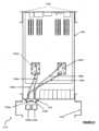
またさらなる態様では、ラック(またはサーバラック)に設置するように構成された、電子モジュール(またはサーバモジュール)を冷却するためのシステムが説明される。システムは、電子モジュール内に搭載された少なくとも第1のコールドプレートおよび第2のコールドプレート(またはコールドプレートモジュールもしくはコールドプレートアセンブリ)を備え、当該コールドプレートを通じて、液体冷却剤(例えば水、または誘電性流体であってもよい)が冷却ループ内で循環する。第1のコールドプレートおよび第2のコールドプレートは各々、冷却ループの別個の並列分岐上に配置される。液体冷却剤がコールドプレートを通って循環する間、熱は、コールドプレートに熱的に結合された1つまたは複数の電子デバイスから第1のコールドプレートおよび第2のコールドプレートの各々を通過する液体冷却剤に伝達される。冷却システムは、冷却ループ内を循環する液体から外方に熱を除去するかまたは熱を伝達するために、冷却ループ内に接続される。液体冷却剤は、電子モジュールのシャーシまたはハウジングの外部または内部のいずれに配置されてもよい。In yet a further aspect, a system for cooling an electronic module (or server module) configured for installation in a rack (or server rack) is described. The system comprises at least a first cold plate and a second cold plate (or a cold plate module or cold plate assembly) mounted in the electronic module through which a liquid coolant (which may be, for example, water or a dielectric fluid) circulates in a cooling loop. The first cold plate and the second cold plate are each disposed on a separate parallel branch of the cooling loop. As the liquid coolant circulates through the cold plates, heat is transferred from one or more electronic devices thermally coupled to the cold plates to the liquid coolant passing through each of the first cold plate and the second cold plate. A cooling system is connected in the cooling loop to remove or transfer heat outward from the liquid circulating in the cooling loop. The liquid coolant may be disposed either externally or internally to the chassis or housing of the electronic module.
さらなる態様では、電子モジュールのモジュールハウジング内に搭載された第1のコールドプレートおよび第2のコールドプレートを備える、ラックに設置するように構成された電子モジュールを冷却するためのシステムがある。各コールドプレートはハウジングを備え、ハウジングの表面は、それに熱的に結合された電子デバイスを冷却するための熱界面を提供するように構成される。各コールドプレートは、熱界面によって受け取られる熱が液体冷却剤に伝達されるように液体冷却剤が流れるように構成された、ハウジング内にあり、表面に近接する少なくとも1つのチャネルをさらに含む。システムの第1のコールドプレートおよび第2のコールドプレートは、冷却ループ内で並列に結合され、冷却ループは液体冷却剤を循環させるように構成される。In a further aspect, there is a system for cooling an electronic module configured for installation in a rack, comprising a first cold plate and a second cold plate mounted within a module housing of the electronic module. Each cold plate comprises a housing, a surface of the housing configured to provide a thermal interface for cooling an electronic device thermally coupled thereto. Each cold plate further includes at least one channel within the housing and proximate the surface configured for liquid coolant to flow therethrough such that heat received by the thermal interface is transferred to the liquid coolant. The first cold plate and the second cold plate of the system are coupled in parallel within a cooling loop, the cooling loop configured to circulate the liquid coolant.
好ましくは、システムは、冷却システムであって、冷却システムは、液体冷却剤から熱を除去するように構成されている、冷却システムと、冷却ループ内を循環する液体冷却剤を第1のコールドプレートおよび第2のコールドプレートならびに冷却システムの間で移送するために、第1のコールドプレートおよび第2のコールドプレートならびに冷却システムに結合された複数の導管とをさらに備える。導管は、パイプまたは配管であってもよく、これは、電子モジュール内の構成要素の周りに導管を配置することを可能にするために、好ましくは可撓性である。パイプは、電子モジュール内の構成要素の既存の構成内での配置を助けるために、空孔のサイズまたは直径が小さくてもよい(例えば、2~20mm、より好ましくは3~10mm)。これはまた、モジュールハウジングまたはシャーシ内の既存の孔、開口部または開口を通るパイプまたはチューブの貫通を可能にするのにも有益である。冷却システムは少なくとも、液体冷却剤から別の冷却媒体(第2の液体冷却剤、または空気など)に熱を伝達するための熱交換器を備えることができる。冷却システムは、電子モジュールのハウジングまたはシャーシ内に配置されてもよく、またはモジュールの外部に配置されてもよい。Preferably, the system further comprises a cooling system configured to remove heat from the liquid coolant, and a plurality of conduits coupled to the first and second cold plates and the cooling system for transporting the liquid coolant circulating in the cooling loop between the first and second cold plates and the cooling system. The conduits may be pipes or tubing, which are preferably flexible to allow for placement of the conduits around components in the electronic module. The pipes may have small void sizes or diameters (e.g., 2-20 mm, more preferably 3-10 mm) to aid placement within an existing configuration of components in the electronic module. This is also beneficial to allow for the passage of the pipes or tubes through existing holes, openings or apertures in the module housing or chassis. The cooling system may comprise at least a heat exchanger for transferring heat from the liquid coolant to another cooling medium (such as a second liquid coolant or air). The cooling system may be located within the housing or chassis of the electronic module, or may be located external to the module.
好ましくは、複数の導管は少なくとも、第1のコールドプレートに結合された第1の入力導管と、第2のコールドプレートに結合された第2の入力導管と、第1の入力導管および第2の入力導管が並列に結合されている供給導管と、第1のコールドプレートに結合された第1の出力導管と、第2のコールドプレートに結合された第2の出力導管と、第1の出力導管および第2の出力導管が並列に結合された受け入れ導管とを備える。言い換えれば、複数の導管は少なくとも、冷却ループの第1の並列分岐および第2の並列分岐(それぞれ第1の入力導管および第1の出力導管、ならびに、第2の入力導管および第2の出力導管)を形成する導管と、冷却ループの並列分岐に液体冷却剤を供給しまたは受け取るための2つのさらなる導管とを含む。Preferably, the plurality of conduits comprises at least a first input conduit coupled to the first cold plate, a second input conduit coupled to the second cold plate, a supply conduit to which the first input conduit and the second input conduit are coupled in parallel, a first output conduit coupled to the first cold plate, a second output conduit coupled to the second cold plate, and a receiving conduit to which the first output conduit and the second output conduit are coupled in parallel. In other words, the plurality of conduits includes at least conduits forming a first parallel branch and a second parallel branch of the cooling loop (the first input conduit and the first output conduit, and the second input conduit and the second output conduit, respectively), and two further conduits for supplying or receiving liquid coolant to the parallel branches of the cooling loop.
第1の入力導管および第2の入力導管ならびに供給導管の間の結合、ならびに第1の出力導管および第2の出力導管ならびに受け入れ導管との間の結合は、両方ともモジュールハウジング内に配置されてもよい。この場合、供給導管および受け入れ導管は、モジュールハウジングの壁の開口部を通過するように配置される。あるいは、第1の入力導管および第2の入力導管ならびに供給導管の間の結合、ならびに第1の出力導管および第2の出力導管ならびに受け入れ導管との間の結合は、モジュールハウジングの外部に配置されてもよい。この場合、第1の入力導管および第2の入力導管ならびに第1の出力導管および第2の出力導管は、モジュールハウジングの壁の開口部を通過するように配置される。The couplings between the first and second input conduits and the supply conduit, and the couplings between the first and second output conduits and the receiving conduit may both be located within the module housing. In this case, the supply conduit and the receiving conduit are arranged to pass through an opening in the wall of the module housing. Alternatively, the couplings between the first and second input conduits and the supply conduit, and the couplings between the first and second output conduits and the receiving conduit may be located outside the module housing. In this case, the first and second input conduits and the first and second output conduits are arranged to pass through an opening in the wall of the module housing.
任意選択的に、システムは、第1の入力導管および第2の入力導管を供給導管に結合するための、および/または第1の出力導管および第2の出力導管を受け入れ導管に結合するためのマニホールドをさらに備える。任意選択的に、システムは、供給導管を複数の導管のうちの第1のさらなる導管に結合するための、および/または受け入れ導管を複数の導管のうちの第2のさらなる導管に結合するためのマニホールドを備える。マニホールドは、導管を接合または結合するためのユニットであってもよい。有益なことに、マニホールドは、より堅牢な結合を提供することができる。マニホールドは、入力導管および供給導管、ならびに出力導管および受け入れ導管を結合するための単一のユニット(適切な仕切りを有する)であってもよい。しかしながら、各々が冷却ループの供給側および受け入れ側に関連付けられた2つのマニホールドが使用されてもよい。Optionally, the system further comprises a manifold for coupling the first and second input conduits to the supply conduit and/or the first and second output conduits to the receiving conduit. Optionally, the system comprises a manifold for coupling the supply conduit to a first further conduit of the plurality of conduits and/or the receiving conduit to a second further conduit of the plurality of conduits. The manifold may be a unit for joining or coupling the conduits. Advantageously, the manifold may provide a more robust coupling. The manifold may be a single unit (with appropriate partitions) for coupling the input and supply conduits and the output and receiving conduits. However, two manifolds may be used, each associated with a supply side and a receiving side of the cooling loop.
システムは、第1の入力導管および第2の入力導管ならびに/または第1の出力導管および第2の出力導管をマニホールドに接続するための少なくとも1つのコネクタを備えることができる。システムは、供給導管および/または受け入れ導管をマニホールドに接続するための少なくとも1つのコネクタを備えることができる。導管をマニホールドに接続するために、任意のタイプの適切なコネクタを使用することができる。一例では、設置者による直接的な手動操作を必要とする、滴りのない手動コネクタが使用される。さらなる例では、ブラインドメイトコネクタが使用されてもよく、これは、コネクタをともに嵌合してシールするための特定の操作を必要としない押し込み式コネクタである。手動で接続された滴りのないコネクタは、開口部または開口がある場合はいつでもチューブがモジュールハウジングから出ることができるため、既存のITと有利に接続することができる。ブラインドメイトコネクタは、各電子モジュールに特注のブラケットを必要とするが、より容易な嵌合を提供することができる。The system may include at least one connector for connecting the first and second input conduits and/or the first and second output conduits to the manifold. The system may include at least one connector for connecting the supply conduit and/or the receiving conduit to the manifold. Any type of suitable connector may be used to connect the conduits to the manifold. In one example, a drip-free manual connector is used, which requires direct manual manipulation by the installer. In a further example, a blind-mate connector may be used, which is a push-fit connector that does not require specific manipulation to mate and seal the connectors together. A manually connected drip-free connector may advantageously interface with existing IT, since the tubes can exit the module housing whenever there is an opening or aperture. A blind-mate connector requires a custom bracket for each electronic module, but may provide easier mating.
一例では、システムは、マニホールドをモジュールハウジングに固定するためのブラケットを備えることができる。さらなる例では、システムは、マニホールドをラックに固定するためのブラケットを備えることができる。電子モジュールへのマニホールドのラックへの搭載は、ラック内で利用可能なスペースおよびシステムの要件に従って選択することができる。マニホールドの電子モジュールへの接続は、導管間の接続部上での動きおよび歪みを低減することができる。しかしながら、マニホールドのラックへの接続は、よりコンパクトであり得、強打されるかまたは偶発的な損傷に遭遇する可能性が低い。In one example, the system may include a bracket for securing the manifold to the module housing. In a further example, the system may include a bracket for securing the manifold to the rack. Mounting of the manifold to the electronics module on the rack may be selected according to the space available in the rack and the requirements of the system. The connection of the manifold to the electronics module may reduce movement and strain on the connections between the conduits. However, the connection of the manifold to the rack may be more compact and less likely to be banged up or encounter accidental damage.
特定の有利な例では、マニホールドは、電子モジュールに接続されたケーブルを通すためにラック内に画定されたダクト内で、ラックに搭載されてもよい。上述したように、電子モジュールおよびラックは、典型的には、業界標準に準拠している。一般に、ラックは、個々の電子モジュールに接続する前に、電子ケーブルおよびデータケーブルを収容または通過させることができる後方キャビティ、部分またはダクトを含む。このキャビティまたはダクトは、内部に搭載された1つまたは複数のマニホールドを収容するために使用することができる。これにより、より堅牢なシステムが提供され、マニホールドはダクトによって保護され、部分的に封入される。ダクトの壁はまた、マニホールドのための適切な固定点を提供する(特に、ダクトは、典型的には、ケーブルの貫通または固定のための孔の既存の開口を含むため)。In certain advantageous examples, the manifolds may be mounted to the rack within ducts defined within the rack for passing cables connected to the electronic modules. As mentioned above, the electronic modules and racks typically conform to industry standards. Generally, the rack includes a rear cavity, portion or duct through which electronic and data cables can be housed or passed prior to connection to the individual electronic modules. This cavity or duct can be used to house one or more manifolds mounted therein. This provides a more robust system, with the manifolds protected and partially enclosed by the duct. The walls of the duct also provide suitable fastening points for the manifolds (especially since the duct typically includes pre-existing openings for holes for cable penetration or fastening).
好ましくは、システムは、第3のコールドプレートを備え、第3のコールドプレートは、冷却ループ内の第1のコールドプレートまたは第2のコールドプレートのいずれかと直列に結合される。実際、システムは、4つ以上または任意の数のコールドプレートを備えることができる。特に、システムは、冷却ループの各並列分岐上に2つ以上のコールドプレートを含むことができる。例えば、冷却ループの第1の並列分岐は、単一の第1のコールドプレートを含むことができ、冷却ループの第2の並列分岐は、第2のコールドプレートおよび第3のコールドプレートを含むことができ、第2のコールドプレートおよび第3のコールドプレート自体は直列に配置される。3つ以上のコールドプレートを、冷却ループの各並列分岐上に直列に配置することができる。Preferably, the system includes a third cold plate, which is coupled in series with either the first or second cold plate in the cooling loop. In fact, the system can include four or more or any number of cold plates. In particular, the system can include two or more cold plates on each parallel branch of the cooling loop. For example, the first parallel branch of the cooling loop can include a single first cold plate, and the second parallel branch of the cooling loop can include a second cold plate and a third cold plate, which are themselves arranged in series. Three or more cold plates can be arranged in series on each parallel branch of the cooling loop.
さらに、冷却ループの3つ以上の並列分岐が電子モジュール内に配置されてもよく、各並列分岐は、その上に接続された1つまたは複数のコールドプレートを有する。冷却ループの特定の並列分岐上に2つ以上のコールドプレートが配置される場合、追加のコールドプレートは所与の分岐上に直列に配置することができる。Additionally, three or more parallel branches of a cooling loop may be disposed within an electronics module, with each parallel branch having one or more cold plates connected thereto. If more than one cold plate is disposed on a particular parallel branch of a cooling loop, additional cold plates may be disposed in series on a given branch.
有利には、記載されているシステムは、例えば、個別にもしくはグループで、並列もしくは直列に、または両方の混合として、コールドプレートを通る液体冷却剤の循環を可能にすることができる。Advantageously, the described system can allow for the circulation of liquid coolant through the cold plates, for example, individually or in groups, in parallel or in series, or as a mixture of both.
さらなる態様では、ラック内に設置するように構成された電子モジュールを冷却するための方法であって、冷却ループを巡って液体冷却剤を循環させるステップを含み、第1のコールドプレートおよび第2のコールドプレートが冷却ループ内で並列に結合され、第1のコールドプレートおよび第2のコールドプレートが電子モジュールのモジュールハウジング内に収容される、方法が説明される。第1のコールドプレートおよび第2のコールドプレートの各々は、ハウジングであって、ハウジングの表面は、ハウジングに熱的に結合された電子デバイスを冷却するための熱界面を提供するように構成されている、ハウジングと、ハウジング内の、表面に近接している少なくとも1つのチャネルであって、熱界面によって受け取られる熱が液体冷却剤に伝達されるように液体冷却剤が当該チャネルを流れるように構成されている、少なくとも1つのチャネルとを備える。冷却のためのシステムに関して本開示内で言及されている特徴の各々は、この本態様の冷却のための方法によって実施することができる。In a further aspect, a method for cooling an electronic module configured for installation in a rack is described, comprising circulating a liquid coolant around a cooling loop, where a first cold plate and a second cold plate are coupled in parallel in the cooling loop, and the first cold plate and the second cold plate are contained within a module housing of the electronic module. Each of the first cold plate and the second cold plate comprises a housing, where a surface of the housing is configured to provide a thermal interface for cooling an electronic device thermally coupled to the housing, and at least one channel in the housing proximate the surface, where the liquid coolant is configured to flow through the channel such that heat received by the thermal interface is transferred to the liquid coolant. Each of the features mentioned in this disclosure with respect to the system for cooling can be implemented by the method for cooling of this aspect.
本開示に記載の冷却システムは、ラック(またはサーバラック)に設置するように構成されたタイプの典型的または標準的な電子モジュール(またはサーバモジュール)内に収めることができる。特に、説明した冷却システムは、有利には、既存の電子モジュール(またはサーバラック内のサーバモジュールのパネル)に後付けすることができる。記載されている冷却システムは、一般的な、または大量生産されたサーバモジュール内で典型的な空冷式システムなどの既存の冷却システムに置き換えるために使用することができる。そのような空冷システムは、一般に、サーバモジュールのシャーシ内に空冷式ヒートシンクを含み、これは、取り外して、本開示の冷却システムの一部として説明されるコールドプレートと交換することができる。したがって、「フットプリント」(すなわち、サーバモジュールの平面内の各コールドプレートの寸法、例えば50mm×50mm~150mm×150mm)は、この種のサーバモジュールにおいて使用される典型的な空冷式ヒートシンクと同じまたは同様であってもよい。The cooling system described in this disclosure can be housed within a typical or standard electronic module (or server module) of the type configured for installation in a rack (or server rack). In particular, the described cooling system can be advantageously retrofitted to an existing electronic module (or panel of a server module in a server rack). The described cooling system can be used to replace an existing cooling system, such as a typical air-cooled system, in a generic or mass-produced server module. Such an air-cooling system typically includes an air-cooled heat sink within the chassis of the server module, which can be removed and replaced with a cold plate described as part of the cooling system of the present disclosure. Thus, the "footprint" (i.e., the dimensions of each cold plate in the plane of the server module, e.g., 50 mm x 50 mm to 150 mm x 150 mm) may be the same or similar to a typical air-cooled heat sink used in this type of server module.
有利には、液冷式コールドプレートに基づく本開示の冷却システムは、交換が意図されている空冷式システムよりも効率的であり、より大きな冷却能を提供する。電子モジュールまたはサーバモジュールのためのより効率的な冷却システムを提供することにより、より多数の構成要素を特定の電子モジュールに含めることが可能になり(したがって、空間効率が改善され)、および/または電子モジュール内の構成要素をより高い電力性能率で動作させることが可能になる。特に、記載されているコールドプレート(および冷却システム)を使用すると、記載されているシステムが熱を除去するのにより効果的であるため、電子モジュール内の構成要素(CPUなど)をより高い速度でより長く動作させることができる。したがって、説明した冷却システムを提供することにより、従来技術のシステムに見られる十分な冷却の課題の結果として、コンピューティング性能および電子モジュールまたはサーバモジュール内のスペースの使用に現在課されている制限のいくつかが取り除かれる。Advantageously, the disclosed cooling system based on liquid-cooled cold plates is more efficient and provides greater cooling capacity than the air-cooled systems it is intended to replace. Providing a more efficient cooling system for an electronic or server module allows a greater number of components to be included in a particular electronic module (thus improving space efficiency) and/or allows components within the electronic module to operate at higher power performance ratios. In particular, using the described cold plates (and cooling systems) allows components within the electronic module (such as CPUs) to operate at higher speeds and for longer because the described systems are more effective at removing heat. Thus, providing the described cooling system removes some of the limitations currently imposed on computing performance and use of space within an electronic or server module as a result of the challenges of adequate cooling found in prior art systems.
したがって、本開示に記載の冷却システムを、代替の冷却システムを以前に利用していた既存の電子モジュール内に後付けすることが特に有益である。このように、またさらなる態様では、ラックに設置するように構成された電子モジュールのための液冷式システムを設置する方法であって、電子モジュールのモジュールハウジング内に収容された空冷式ヒートシンクを取り外すステップと、空冷式ヒートシンクの以前の位置において、モジュールハウジング内にコールドプレートを搭載するステップと、入力導管をコールドプレートの入口冷却ポートに結合するステップと、出力導管をコールドプレートの出口冷却ポートに結合するステップと、液体冷却剤流体ループを巡って循環する液体冷却剤が少なくとも入力導管、コールドプレート、および出力導管を通過するように、入力導管と出力導管とを液体冷却剤流体ループ内で接続するステップとを含む、方法が提供される。第1のコールドプレートおよび第2のコールドプレートの各々は、ハウジングであって、ハウジングの表面は、ハウジングに熱的に結合された電子デバイスを冷却するための熱界面を提供するように構成されている、ハウジングと、ハウジング内の、表面に近接している少なくとも1つのチャネルであって、熱界面によって受け取られる熱が液体冷却剤に伝達されるように液体冷却剤が当該チャネルを流れるように構成されている、少なくとも1つのチャネルと、液体冷却剤を少なくとも1つのチャネルに移送するための、ハウジングの外部に延在する入口冷却剤ポートと、液体冷却剤を少なくとも1つのチャネルから移送するための、ハウジングの外部に延在する出口冷却剤ポートとを備えることができる。この方法に従って2つ以上のコールドプレートを取り付けることができることが理解されよう。特に、2つ以上の空冷式ヒートシンクを電子モジュールから取り外し、それぞれの2つ以上のコールドプレートと交換することができる。2つ以上のコールドプレートは、(上記の態様で説明したように)冷却ループ内に並列に嵌合して配置することができ、または代替的に、冷却ループ内に直列に配置することができる。It is therefore particularly beneficial to retrofit the cooling system described herein into an existing electronic module that previously utilized an alternative cooling system. Thus, in yet a further aspect, a method of installing a liquid-cooled system for an electronic module configured for installation in a rack is provided, the method comprising the steps of removing an air-cooled heat sink contained within a module housing of the electronic module, mounting a cold plate within the module housing at the previous location of the air-cooled heat sink, coupling an input conduit to an inlet cooling port of the cold plate, coupling an output conduit to an outlet cooling port of the cold plate, and connecting the input conduit and the output conduit in a liquid coolant fluid loop such that liquid coolant circulating around the liquid coolant fluid loop passes through at least the input conduit, the cold plate, and the output conduit. Each of the first and second cold plates may include a housing, the surface of the housing being configured to provide a thermal interface for cooling an electronic device thermally coupled to the housing, at least one channel in the housing proximate the surface, the at least one channel being configured for liquid coolant to flow through the channel such that heat received by the thermal interface is transferred to the liquid coolant, an inlet coolant port extending to the exterior of the housing for transporting the liquid coolant to the at least one channel, and an outlet coolant port extending to the exterior of the housing for transporting the liquid coolant from the at least one channel. It will be appreciated that more than one cold plate may be installed according to this method. In particular, two or more air-cooled heat sinks may be removed from the electronic module and replaced with two or more respective cold plates. The two or more cold plates may be arranged in a parallel fit in the cooling loop (as described in the above aspect) or, alternatively, may be arranged in series in the cooling loop.
好ましくは、方法は、モジュールハウジングの壁の開口部を通過するように入力導管および出力導管を配置するステップをさらに含む。Preferably, the method further includes the step of positioning the input conduit and the output conduit to pass through openings in a wall of the module housing.
好ましくは、液体冷却剤流体ループ内で入力導管と出力導管とを接続するステップは、入力導管をマニホールドの第1の出口ポートに結合することと、出力導管をマニホールドの第1の入口ポートに結合することと、液体冷却剤を熱交換器からマニホールドに移送するために、供給導管をマニホールドの第2の入口ポートに結合することと、液体冷却剤をマニホールドから熱交換器に移送するために、受け入れ導管をマニホールドの第2の出口ポートに結合することとを含むことができる。Preferably, the step of connecting the input conduit and the output conduit in the liquid coolant fluid loop may include coupling the input conduit to a first outlet port of the manifold, coupling the output conduit to a first inlet port of the manifold, coupling a supply conduit to a second inlet port of the manifold for transferring the liquid coolant from the heat exchanger to the manifold, and coupling a receiving conduit to a second outlet port of the manifold for transferring the liquid coolant from the manifold to the heat exchanger.
任意選択的に、本方法は、マニホールドをラックに固定するステップをさらに含む。一例では、マニホールドをラックに固定するステップは、電子モジュールに接続されたケーブルを通すために、ラック内に画定されたダクト内にマニホールドを固定することを含む。Optionally, the method further includes securing the manifold to the rack. In one example, securing the manifold to the rack includes securing the manifold within a duct defined in the rack for routing cables connected to the electronic modules.
方法は、供給導管と受け入れ導管との間に熱交換器を接続するステップをさらに含むことができ、熱交換器は液体冷却剤から外方に熱を伝達するように構成される。この方法はまた、供給導管と受け入れ導管との間にポンプを接続するステップを含んでもよく、ポンプは液体冷却剤流体ループを巡って液体冷却剤を循環させるように構成される。The method may further include connecting a heat exchanger between the supply conduit and the receiving conduit, the heat exchanger configured to transfer heat outwardly from the liquid coolant. The method may also include connecting a pump between the supply conduit and the receiving conduit, the pump configured to circulate the liquid coolant around the liquid coolant fluid loop.
あるいは、例えば、マニホールドが冷却ループ内に存在しない場合、熱交換器は、入力導管と出力導管との間に接続されてもよい。同様に、ポンプは、入力導管と出力導管との間に接続されてもよい。この例は、冷却ループ全体が電子モジュールのモジュールハウジング内に存在する場合に使用することができる。したがって、ポンプ、冷却システム(または熱交換器)、およびコールドプレートはすべてモジュールハウジング内にある。冷却システムは、冷却ループ内の液体冷却剤から外方に、別の媒体(ハウジングを通過するように配置された第2の冷却ループなどに熱を伝達するために使用することができる。Alternatively, for example, if no manifold is present in the cooling loop, a heat exchanger may be connected between the input and output conduits. Similarly, a pump may be connected between the input and output conduits. This example can be used when the entire cooling loop is present within the module housing of the electronics module. Thus, the pump, cooling system (or heat exchanger), and cold plate are all within the module housing. The cooling system can be used to transfer heat from the liquid coolant in the cooling loop outwardly to another medium (such as a second cooling loop arranged to pass through the housing).
なおまたさらなる態様では、上述の設置する方法において使用するためのキットが開示される。キットは、少なくとも1つのコールドプレートと、入力導管として使用するための第1のパイプと、第2の導管として使用するための第2のパイプとを備えることができる。キットは、例えば、他の態様に関連して上述した構成要素のいずれかを含み得る。各構成要素に関して上述したオプション、特性、および利点は、この態様に適用される。In still yet a further aspect, a kit is disclosed for use in the above-described installation method. The kit may include at least one cold plate, a first pipe for use as an input conduit, and a second pipe for use as a second conduit. The kit may include, for example, any of the components described above in connection with other aspects. The options, features, and advantages described above with respect to each component apply to this aspect.
好ましくは、コールドプレートの入口冷却剤ポートおよび出口冷却剤ポートは各々、独立して回転する流体コネクタを備え、それによって、それぞれの冷却剤ポートに結合された第1のパイプまたは第2のパイプの方向の調整を可能にする。Preferably, the inlet and outlet coolant ports of the cold plate each include an independently rotating fluid connector, thereby allowing adjustment of the orientation of the first or second pipe coupled to the respective coolant port.
好ましくは、コールドプレートは、少なくとも1つのチャネル内に配置されたピンおよび/またはフィンをさらに備える。任意選択的に、ピンおよび/またはフィンは、熱界面を提供するように構成されたハウジングの表面の近位にある少なくとも1つのチャネルの底面から、熱界面を提供するように構成されたハウジングの表面の遠位にある少なくとも1つのチャネルの上面まで延在するように構成される。Preferably, the cold plate further comprises pins and/or fins disposed within the at least one channel. Optionally, the pins and/or fins are configured to extend from a bottom surface of the at least one channel proximal to a surface of the housing configured to provide a thermal interface to a top surface of the at least one channel distal to a surface of the housing configured to provide a thermal interface.
好ましくは、キットは、液体冷却剤流体ループ内で入力導管および出力導管を接続するためのマニホールドをさらに備え、マニホールドは、出力導管に結合するための第1の入口ポートと、入力導管に結合するための第1の出口ポートと、供給導管を通してマニホールドにおいて液体冷却剤を受け取るための第2の入口ポートと、受け入れ導管を通じてマニホールドから液体冷却剤を移送するための第2の出口ポートとを備える。任意選択的に、例えば、それぞれ、入力導管を供給導管に結合するため、および出力導管を受け入れ導管に結合するために、2つの別個のマニホールドを設けることができ、2つのマニホールドは適切なポートを有する。Preferably, the kit further comprises a manifold for connecting the input and output conduits in a liquid coolant fluid loop, the manifold comprising a first inlet port for coupling to the output conduit, a first outlet port for coupling to the input conduit, a second inlet port for receiving liquid coolant at the manifold through a supply conduit, and a second outlet port for transferring liquid coolant from the manifold through a receiving conduit. Optionally, for example, two separate manifolds can be provided for coupling the input conduit to the supply conduit and the output conduit to the receiving conduit, respectively, the two manifolds having appropriate ports.
任意選択的に、マニホールドは、ラックに固定されるように構成され、より好ましくは、電子モジュールに接続するためのケーブルを通すためにラック内に画定されたダクト内で、ラックに固定される。Optionally, the manifold is configured to be secured to the rack, more preferably within a duct defined in the rack for passing cables for connection to the electronic modules.
キットは、熱交換器および/またはポンプをさらに備えることができる。熱交換器および/またはポンプは、冷却ループの構成に応じて、供給導管と受け入れ導管との間の接続のため、または供給導管と受け入れ導管との間の接続のためのものであってもよい。The kit may further comprise a heat exchanger and/or a pump. The heat exchanger and/or pump may be for connection between the supply conduit and the receiving conduit or for connection between the supply conduit and the receiving conduit, depending on the configuration of the cooling loop.
またさらなる例では、ラックに設置するように構成された電子モジュールを冷却するためのシステムであって、第1の液体冷却剤が循環される第1の冷却ループであって、第1の冷却剤ループは、少なくとも1つのコールドプレートを備える、第1の冷却ループと、第2の液体冷却剤が循環される第2の冷却ループと、第1の液体冷却剤から第2の液体冷却剤へ熱を伝達するための冷却システムとを備え、第1の冷却剤ループおよび冷却システムは、電子モジュールのハウジング内に収容される、システムが存在する。In yet a further example, there is a system for cooling an electronic module configured for installation in a rack, the system comprising: a first cooling loop through which a first liquid coolant is circulated, the first coolant loop comprising at least one cold plate; a second cooling loop through which a second liquid coolant is circulated; and a cooling system for transferring heat from the first liquid coolant to the second liquid coolant, the first coolant loop and the cooling system being contained within a housing of the electronic module.
第1の冷却ループおよび第2の冷却ループは、それぞれ第1の冷却循環装置および第2の冷却循環装置と考えることができる。有益なことに、記載されている構成は、少なくとも1つのコールドプレートを通って循環する第1の液体冷却剤を完全に電子モジュール内に保持することを可能にする(すなわち、電子モジュールのハウジングまたはシャーシ内に封入される)。このように、電子モジュールがラックから設置されるかまたは取り外されると、第1の冷却剤ループへの接続または接続切断は必要とされず、第1の冷却剤ループは設置プロセス全体を通して「閉ループ」である。したがって、高価で時には有毒な冷却剤流体の漏れまたは損失のリスクを低減または回避することができる。さらに、異なる種類の冷却剤流体(例えば、より高価な誘電性液体)を第1の液体冷却剤として使用することができ、第2のより豊富に利用可能な流体(例えば、水)を第2の液体冷却剤として使用することができる。第2の液体冷却剤として水を使用することは、大流量を可能にし、冷却能を増加させるのに役立つことができるが、有利には、記載されている構成は、第2の液体冷却剤を、シャーシ内に収容された任意の電気構成要素または電子デバイスから離して維持することができる。The first and second cooling loops can be considered as a first and second cooling circulation device, respectively. Beneficially, the described configuration allows the first liquid coolant circulating through at least one cold plate to be kept entirely within the electronic module (i.e., enclosed within the housing or chassis of the electronic module). In this way, no connection or disconnection to the first coolant loop is required when the electronic module is installed or removed from the rack, and the first coolant loop is "closed loop" throughout the entire installation process. Thus, the risk of leakage or loss of expensive and sometimes toxic coolant fluid can be reduced or avoided. Furthermore, a different type of coolant fluid (e.g., a more expensive dielectric liquid) can be used as the first liquid coolant, and a second, more abundantly available fluid (e.g., water) can be used as the second liquid coolant. While using water as the second liquid coolant can help allow for high flow rates and increased cooling capacity, advantageously, the described configuration allows the second liquid coolant to be maintained away from any electrical components or electronic devices housed within the chassis.
好ましくは、各コールドプレートは、ハウジングであって、ハウジングの表面は、ハウジングに熱的に結合された電子デバイスを冷却するための熱界面を提供するように構成されている、ハウジングと、ハウジング内の、表面に近接している少なくとも1つのチャネルであって、熱界面によって受け取られる熱が第1の液体冷却剤に伝達されるように第1の液体冷却剤が当該チャネルを流れるように構成されている、少なくとも1つのチャネルとを備える。Preferably, each cold plate comprises a housing, the surface of the housing being configured to provide a thermal interface for cooling an electronic device thermally coupled to the housing, and at least one channel within the housing proximate the surface, the channel being configured for a first liquid coolant to flow through the channel such that heat received by the thermal interface is transferred to the first liquid coolant.
任意選択的に、第1の冷却剤ループは、電子モジュールのハウジング内に搭載された第1のコールドプレートおよび第2のコールドプレートを備え、第1のコールドプレートおよび第2のコールドプレートは、第1の冷却ループ内で並列に結合される。Optionally, the first coolant loop comprises a first cold plate and a second cold plate mounted within the housing of the electronic module, the first cold plate and the second cold plate being coupled in parallel within the first cooling loop.
好ましくは、第1の冷却ループは、第1の冷却ループを巡って第1の液体冷却剤を循環させるためのポンプをさらに備え、ポンプは、電子モジュールのハウジングまたはシャーシ内に収容される。Preferably, the first cooling loop further comprises a pump for circulating the first liquid coolant around the first cooling loop, the pump being contained within a housing or chassis of the electronic module.
好ましくは、冷却システムは熱交換器である。任意選択的に、冷却システムは第1の冷却システムであり、第2の冷却ループは、第2の液体冷却剤から外方に熱を伝達するための第2の冷却システムをさらに備える。Preferably, the cooling system is a heat exchanger. Optionally, the cooling system is a first cooling system and the second cooling loop further comprises a second cooling system for transferring heat outwardly from the second liquid coolant.
好ましくは、第2の冷却ループは、第2の冷却ループを巡って第2の液体冷却剤を循環させるためのポンプをさらに備える。Preferably, the second cooling loop further comprises a pump for circulating the second liquid coolant around the second cooling loop.
以下の番号が付けられた項は、例示的な例のみを示す。
1.ラックに設置するように構成された電子モジュールを冷却するためのシステムであって、
電子モジュールのモジュールハウジング内に搭載された第1のコールドプレートおよび第2のコールドプレートを備え、各コールドプレートは、
ハウジングであって、ハウジングの表面は、ハウジングに熱的に結合された電子デバイスを冷却するための熱界面を提供するように配置されている、ハウジングと、
ハウジング内の、表面に近接する少なくとも1つのチャネルであって、熱界面によって受け取られる熱が液体冷却剤に伝達されるように、液体冷却剤が流れるように構成された少なくとも1つのチャネルとを備え、
第1のコールドプレートおよび第2のコールドプレートは、冷却ループ内で並列に結合され、冷却ループは、液体冷却剤を循環させるように構成されている、システム。 The following numbered paragraphs provide illustrative examples only.
1. A system for cooling electronic modules configured for installation in a rack, comprising:
a first cold plate and a second cold plate mounted within a module housing of the electronic module, each cold plate comprising:
a housing, a surface of the housing arranged to provide a thermal interface for cooling an electronic device thermally coupled to the housing;
at least one channel within the housing and proximate the surface, the at least one channel configured for liquid coolant to flow therethrough such that heat received by the thermal interface is transferred to the liquid coolant;
The system, wherein the first cold plate and the second cold plate are coupled in parallel in a cooling loop, the cooling loop being configured to circulate a liquid coolant.
2.冷却システムであって、冷却システムは、液体冷却剤から熱を除去するように構成されている、冷却システムと、冷却ループ内を循環する液体冷却剤を第1のコールドプレートおよび第2のコールドプレートならびに冷却システムの間で移送するために、第1のコールドプレートおよび第2のコールドプレートならびに冷却システムに結合された複数の導管とをさらに備える、項1に記載のシステム。2. The system of claim 1, further comprising a cooling system configured to remove heat from a liquid coolant, and a plurality of conduits coupled to the first and second cold plates and the cooling system for transporting liquid coolant circulating in a cooling loop between the first and second cold plates and the cooling system.
3.冷却システムが、液体冷却剤からさらなる冷却媒体に熱を伝達するための熱交換器を備える、項2に記載のシステム。3. The system of claim 2, wherein the cooling system includes a heat exchanger for transferring heat from the liquid coolant to a further cooling medium.
4.複数の導管は少なくとも、
第1のコールドプレートに結合された第1の入力導管と、
第2のコールドプレートに結合された第2の入力導管と、
第1の入力導管および第2の入力導管が並列に結合されている供給導管と、
第1のコールドプレートに結合された第1の出力導管と、
第2のコールドプレートに結合された第2の出力導管と、
第1の出力導管および第2の出力導管が並列に結合された受け入れ導管と
を含む、項2または3に記載のシステム。 4. The plurality of conduits includes at least:
a first input conduit coupled to the first cold plate;
a second input conduit coupled to the second cold plate;
a supply conduit to which the first input conduit and the second input conduit are coupled in parallel;
a first output conduit coupled to the first cold plate;
a second output conduit coupled to the second cold plate;
a receiving conduit to which the first output conduit and the second output conduit are coupled in parallel.
5.第1の入力導管および第2の入力導管ならびに供給導管の間の結合が、モジュールハウジング内に配置されており、
第1の出力導管および第2の出力導管ならびに受け入れ導管の間の結合は、モジュールハウジング内に配置され、
供給導管および受け入れ導管は、モジュールハウジングの壁の開口部を通過するように構成されている、項4に記載のシステム。 5. A connection between the first and second input conduits and the supply conduit is disposed within the module housing;
a coupling between the first and second output conduits and the receiving conduit disposed within the module housing;
5. The system of claim 4, wherein the supply conduit and the receiving conduit are configured to pass through openings in a wall of the module housing.
6.第1の入力導管および第2の入力導管ならびに供給導管の間の結合が、モジュールハウジングの外部に配置されており、
第1の出力導管および第2の出力導管ならびに受け入れ導管の間の結合は、モジュールハウジングの外部に配置され、
第1の入力導管および第2の入力導管ならびに第1の出力導管および第2の出力導管は、モジュールハウジングの壁の開口部を通過するように構成されている、項4に記載のシステム。 6. The coupling between the first and second input conduits and the supply conduit is located external to the module housing;
a coupling between the first and second output conduits and the receiving conduit is disposed external to the module housing;
5. The system of claim 4, wherein the first and second input conduits and the first and second output conduits are configured to pass through an opening in a wall of the module housing.
7.第1の入力導管および第2の入力導管を供給導管に結合するための、および/または第1の出力導管および第2の出力導管を受け入れ導管に結合するためのマニホールドをさらに備える、項4または6に記載のシステム。7. The system of claim 4 or 6, further comprising a manifold for coupling the first input conduit and the second input conduit to a supply conduit and/or for coupling the first output conduit and the second output conduit to a receiving conduit.
8.第1の入力導管および第2の入力導管ならびに/または第1の出力導管および第2の出力導管をマニホールドに接続するための少なくとも1つのコネクタをさらに備える、項7に記載のシステム。8. The system of claim 7, further comprising at least one connector for connecting the first and second input conduits and/or the first and second output conduits to the manifold.
9.供給導管を複数の導管のうちの第1のさらなる導管に結合するための、および/または受け入れ導管を複数の導管のうちの第2のさらなる導管に結合するためのマニホールドをさらに備える、項4~6のいずれか一項に記載のシステム。9. The system of any one of claims 4 to 6, further comprising a manifold for coupling the supply conduit to a first further conduit of the plurality of conduits and/or for coupling the receiving conduit to a second further conduit of the plurality of conduits.
10.供給導管および/または受け入れ導管をマニホールドに接続するための少なくとも1つのコネクタをさらに備える、項9に記載のシステム。10. The system of claim 9, further comprising at least one connector for connecting the supply conduit and/or the receiving conduit to the manifold.
11.マニホールドをモジュールハウジングに固定するためのブラケットをさらに備える、項7~10のいずれか一項に記載のシステム。11. The system described in any one of claims 7 to 10, further comprising a bracket for fixing the manifold to the module housing.
12.マニホールドをラックに固定するためのブラケットをさらに備える、項7~11のいずれか一項に記載のシステム。12. The system described in any one of claims 7 to 11, further comprising a bracket for fixing the manifold to the rack.
13.マニホールドは、電子モジュールに接続されたケーブルを通すためにラック内に画定されたダクト内で、ラックに固定されるように構成されている、項12に記載のシステム。13. The system described in paragraph 12, wherein the manifold is configured to be fixed to the rack within a duct defined in the rack for passing cables connected to the electronic modules.
14.第3のコールドプレートをさらに備え、第3のコールドプレートは、冷却ループ内の第1のコールドプレートまたは第2のコールドプレートのいずれかと直列に結合される、項1~13のいずれか一項に記載のシステム。14. The system of any one of claims 1 to 13, further comprising a third cold plate, the third cold plate being coupled in series with either the first cold plate or the second cold plate in the cooling loop.
15.ラックに設置するように構成された電子モジュールを冷却するための方法であって、
冷却ループを巡って液体冷却剤を循環させるステップを含み、第1のコールドプレートおよび第2のコールドプレートが冷却ループ内で並列に結合され、第1のコールドプレートおよび第2のコールドプレートが電子モジュールのモジュールハウジング内に収容され、さらに、第1のコールドプレートおよび第2のコールドプレートの各々が、
ハウジングであって、ハウジングの表面は、ハウジングに熱的に結合された電子デバイスを冷却するための熱界面を提供するように構成されている、ハウジングと、
熱界面によって受け取られる熱が液体冷却剤に伝達されるように、液体冷却剤が流れるように構成された、ハウジング内の、表面に近接する少なくとも1つのチャネルと
を備える、方法。 15. A method for cooling an electronic module configured for installation in a rack, comprising:
The method includes circulating a liquid coolant around a cooling loop, the first cold plate and the second cold plate being coupled in parallel within the cooling loop, the first cold plate and the second cold plate being contained within a module housing of the electronic module, and each of the first cold plate and the second cold plate being:
a housing, a surface of the housing configured to provide a thermal interface for cooling an electronic device thermally coupled to the housing;
at least one channel within the housing and proximate to the surface configured for liquid coolant to flow therethrough such that heat received by the thermal interface is transferred to the liquid coolant.
16.ラックに設置するように構成された電子モジュールのための液冷式システムを設置する方法であって、
電子モジュールのモジュールハウジング内に収容された空冷式ヒートシンクを取り外すステップと、
空冷式ヒートシンクの以前の位置において、モジュールハウジング内にコールドプレートを搭載するステップであって、コールドプレートは、
ハウジングであって、ハウジングの表面は、ハウジングに熱的に結合された電子デバイスを冷却するための熱界面を提供するように構成されている、ハウジングと、
ハウジング内の、表面に近接する少なくとも1つのチャネルであって、熱界面によって受け取られる熱が液体冷却剤に伝達されるように、液体冷却剤が流れるように構成された少なくとも1つのチャネルと、
液体冷却剤を少なくとも1つのチャネルに移送するための、ハウジングの外部に延在する入口冷却剤ポートと、
少なくとも1つのチャネルから液体冷却剤を移送するための、ハウジングの外部に延在する出口冷却剤ポートと
を備える、コールドプレートを搭載するステップと、
入力導管をコールドプレートの入口冷却ポートに結合するステップと、
出力導管をコールドプレートの出口冷却ポートに結合するステップと、
液体冷却剤流体ループを巡って循環する液体冷却剤が少なくとも入力導管、コールドプレート、および出力導管を通過するように、液体冷却剤流体ループ内で入力導管と出力導管とを接続するステップと
を含む、方法。 16. A method of installing a liquid cooling system for electronic modules configured for installation in a rack, comprising:
Removing an air-cooled heat sink contained within a module housing of the electronic module;
Mounting a cold plate within the module housing at the previous location of the air-cooled heat sink, the cold plate comprising:
a housing, a surface of the housing configured to provide a thermal interface for cooling an electronic device thermally coupled to the housing;
at least one channel within the housing and proximate the surface, the at least one channel configured for liquid coolant to flow therethrough such that heat received by the thermal interface is transferred to the liquid coolant;
an inlet coolant port extending outside the housing for transporting liquid coolant to the at least one channel;
an outlet coolant port extending to an exterior of the housing for transporting liquid coolant from the at least one channel;
coupling an input conduit to an inlet cooling port of a cold plate;
coupling an output conduit to an outlet cooling port of the cold plate;
and connecting an input conduit and an output conduit in a liquid coolant fluid loop such that liquid coolant circulating around the liquid coolant fluid loop passes through at least the input conduit, the cold plate, and the output conduit.
17.モジュールハウジングの壁の開口部を通過するように入力導管および出力導管を配置するステップをさらに含む、項16に記載の方法。17. The method of claim 16, further comprising positioning the input and output conduits through openings in a wall of the module housing.
18.液体冷却剤流体ループ内で入力導管と出力導管とを接続するステップは、
入力導管をマニホールドの第1の出口ポートに結合することと、
出力導管をマニホールドの第1の入口ポートに結合することと、
液体冷却剤を熱交換器からマニホールドに移送するために、供給導管をマニホールドの第2の入口ポートに結合することと、
液体冷却剤をマニホールドから熱交換器に移送するために、受け入れ導管をマニホールドの第2の出口ポートに結合することと
を含む、項16または17に記載の方法。 18. The step of connecting an input conduit and an output conduit in a liquid coolant fluid loop comprises:
coupling an input conduit to a first outlet port of a manifold;
coupling an output conduit to a first inlet port of a manifold;
coupling a supply conduit to a second inlet port of the manifold for transporting liquid coolant from the heat exchanger to the manifold;
and coupling a receiving conduit to the second outlet port of the manifold for transporting liquid coolant from the manifold to the heat exchanger.
19.マニホールドをラックに固定するステップをさらに含む、項18に記載の方法。
20.マニホールドをラックに固定するステップは、電子モジュールに接続されたケーブルを通すために、ラック内に画定されたダクト内にマニホールドを固定することを含む、項19に記載の方法。 19. The method of claim 18, further comprising the step of securing the manifold to a rack.
20. The method of claim 19, wherein the step of securing the manifold to the rack includes securing the manifold within a duct defined in the rack for routing cables connected to the electronic modules.
21.方法は、供給導管と受け入れ導管との間に熱交換器を接続するステップをさらに含み、
熱交換器は液体冷却剤から外方に熱を伝達するように構成される、項18~20のいずれか一項に記載の方法。 21. The method further includes connecting a heat exchanger between the supply conduit and the receiving conduit;
21. The method of any one of clauses 18-20, wherein the heat exchanger is configured to transfer heat outwardly from the liquid coolant.
22.方法は、供給導管と受け入れ導管との間にポンプを接続するステップをさらに含み、ポンプは液体冷却剤流体ループを巡って液体冷却剤を循環させるように構成される、項18~21のいずれか一項に記載の方法。22. The method of any one of claims 18 to 21, further comprising connecting a pump between the supply conduit and the receiving conduit, the pump configured to circulate the liquid coolant around the liquid coolant fluid loop.
23.方法は、入力導管と出力導管との間に熱交換器を接続するステップをさらに含み、熱交換器は液体冷却剤から外方に熱を伝達するように構成される、項16または17のいずれか一項に記載の方法。23. The method of any one of claims 16 or 17, further comprising connecting a heat exchanger between the input conduit and the output conduit, the heat exchanger being configured to transfer heat outwardly from the liquid coolant.
24.方法は、入力導管と出力導管との間にポンプを接続するステップをさらに含み、ポンプは液体冷却剤流体ループを巡って液体冷却剤を循環させるように構成される、項16、17または23に記載の方法。24. The method of claim 16, 17 or 23, further comprising connecting a pump between the input conduit and the output conduit, the pump configured to circulate the liquid coolant around the liquid coolant fluid loop.
25.項16~24の設置する方法において使用するためのキットであって、
コールドプレートと、
入力導管として使用するための第1のパイプと、
第2の導管として使用するための第2のパイプと
を備える、キット。 25. A kit for use in the installation method according to any one of items 16 to 24, comprising:
A cold plate;
a first pipe for use as an input conduit;
a second pipe for use as the second conduit.
26.コールドプレートの入口冷却剤ポートおよび出口冷却剤ポートは各々、独立して回転する流体コネクタを備え、以て、それぞれの冷却剤ポートに結合された第1のパイプまたは第2のパイプの方向の調整を可能にする、項25に記載のキット。26. The kit of claim 25, wherein the inlet and outlet coolant ports of the cold plate each have an independently rotating fluid connector, thereby allowing adjustment of the orientation of the first or second pipe coupled to the respective coolant port.
27.コールドプレートは、少なくとも1つのチャネル内に配置されたピンおよび/またはフィンをさらに備える、項25または26に記載のキット。27. The kit of claim 25 or 26, wherein the cold plate further comprises pins and/or fins disposed within at least one channel.
28.ピンおよび/またはフィンは、熱界面を提供するように構成されたハウジングの表面の近位にある少なくとも1つのチャネルの底面から、熱界面を提供するように構成されたハウジングの表面の遠位にある少なくとも1つのチャネルの上面まで延在するように構成される、項27に記載のキット。28. The kit of claim 27, wherein the pins and/or fins are configured to extend from a bottom surface of at least one channel proximal to a surface of the housing configured to provide a thermal interface to a top surface of at least one channel distal to a surface of the housing configured to provide a thermal interface.
29.キットは、液体冷却剤流体ループ内で入力導管および出力導管を接続するためのマニホールドをさらに備え、マニホールドは、
出力導管に結合するための第1の入口ポートと、
入力導管に結合するための第1の出口ポートと、
供給導管を通してマニホールドにおいて液体冷却剤を受け取るための第2の入口ポートと、
受け入れ導管を通じてマニホールドから液体冷却剤を移送するための第2の出口ポートと
を備える、項25~28のいずれか一項に記載のキット。 29. The kit further comprises a manifold for connecting the input conduit and the output conduit in a liquid coolant fluid loop, the manifold comprising:
a first inlet port for coupling to an output conduit;
a first outlet port for coupling to an input conduit;
a second inlet port for receiving liquid coolant at the manifold through a supply conduit;
and a second outlet port for transferring liquid coolant from the manifold through a receiving conduit.
30.マニホールドは、電子モジュールへの接続のためのケーブルを通すためにラック内に画定されたダクト内で、ラックに固定されるように構成されている、項29に記載のキット。30. The kit of claim 29, wherein the manifold is configured to be secured to the rack within a duct defined in the rack for passing cables for connection to the electronic modules.
31.供給導管と受け入れ導管との間の接続のための熱交換器をさらに備える、項29または30に記載のキット。31. The kit according to claim 29 or 30, further comprising a heat exchanger for connection between the supply conduit and the receiving conduit.
32.キットは、供給導管と受け入れ導管との間の接続のためのポンプをさらに備え、ポンプは液体冷却剤流体ループを巡って液体冷却剤を循環させるように構成される、項29~31のいずれか一項に記載のキット。32. The kit of any one of claims 29 to 31, further comprising a pump for connection between the supply conduit and the receiving conduit, the pump configured to circulate the liquid coolant around the liquid coolant fluid loop.
33.入力導管と出力導管との間の接続のための熱交換器をさらに備える、項25~29のいずれか一項に記載のキット。33. The kit according to any one of claims 25 to 29, further comprising a heat exchanger for connection between the input conduit and the output conduit.
34.キットは、供給導管と受け入れ導管との間の接続のためのポンプをさらに備え、ポンプは液体冷却剤流体ループを巡って液体冷却剤を循環させるように構成される、項25~29または33のいずれか一項に記載のキット。34. The kit of any one of claims 25 to 29 or 33, further comprising a pump for connection between the supply conduit and the receiving conduit, the pump configured to circulate the liquid coolant around the liquid coolant fluid loop.
図面の簡単な説明
本開示は、多くの方法で実践することができ、ここで、好ましい実施形態を、単なる例示として、添付の図面を参照して以下に説明する。 BRIEF DESCRIPTION OF THE DRAWINGS The present disclosure can be practiced in many ways and preferred embodiments will now be described, by way of example only, with reference to the accompanying drawings, in which:
図面において、同様の部分は同様の参照符号によって示されている。図面は原寸に比例して描かれていない。In the drawings, like parts are designated by like reference numerals. The drawings are not drawn to scale.
好ましい実施形態の詳細な説明
液体冷却剤の2つの協働する循環ループを含むハイブリッド冷却システムを有する電子モジュール100が説明される。最初に図1を参照すると、一般的なサーバラック(図示せず)内に収まるように適切な寸法および外側コネクタを有する、モジュールまたはサーバブレードであってもよい電子モジュール100の好ましい実施形態が示されている。同じ電子モジュール100が図2および図3に示されており、これらの図は各々がモジュールの異なる斜視図を示している。 DETAILED DESCRIPTION OF THE PREFERRED EMBODIMENT An
電子モジュールは、外側ハウジングまたは筐体110を有し、基部、壁および蓋を有し、シール可能であってもよい。ハウジング内には、複数の電子デバイス(または発熱構成要素)が搭載されている。場合によっては、構成要素は、ハウジングの基部、蓋、または壁に接続され得るプリント回路基板(PCB)120上に搭載されてもよい。記載されているシステムは、電子デバイスによって発生した熱を電子モジュール内から除去することを目的としている。The electronic module has an outer housing or
第1の冷却循環装置(または第1の冷却ループ)は、電子モジュール内に搭載された複数の電子デバイスのうちの特定の電子デバイスを冷却するために使用される。第2の冷却循環装置(または第2の冷却ループ)は、他の発熱構成要素を冷却するために使用される。例えば、第2の冷却循環装置は、より大きな冷却能を提供され得、したがって、第1の冷却循環装置によって冷却される構成要素よりも大量の熱を生成する特定の構成要素を冷却するために使用することができる。The first cooling circuit (or first cooling loop) is used to cool a particular electronic device among the multiple electronic devices mounted in the electronic module. The second cooling circuit (or second cooling loop) is used to cool other heat-generating components. For example, the second cooling circuit may be provided with a greater cooling capacity and therefore may be used to cool a particular component that generates a greater amount of heat than the component cooled by the first cooling circuit.
図1、図2、および図3に示す例では、電子モジュールは、浸漬冷却を提供する第1の冷却循環装置(または第1の冷却ループ)を有する。第1の冷却循環装置は、電子モジュールのハウジング110内に完全に収容される。特に、第1の液体冷却剤は、電子モジュールのシール可能なハウジング内に収容され、それにより、冷却されるべきいくつかの構成要素115が第1の液体冷却剤に少なくとも部分的に浸漬される。電子モジュールのハウジングの容積に収容される第1の液体冷却剤は、第1の液体冷却剤のリザーバと考えることができる。In the example shown in Figures 1, 2 and 3, the electronic module has a first cooling circuit (or first cooling loop) that provides immersion cooling. The first cooling circuit is contained entirely within the
第1の液体冷却剤のリザーバからの第1の液体冷却剤は、ポンプ入力190において収集または受け取られる。ポンプ入力190は、ポンプ185に向かう液体冷却剤の流れを改善するように成形されてもよい。ポンプ185は、第1の冷却循環装置(または第1の冷却ループ)を通じて第1の液体冷却剤を移動させる。ポンプ185を通過した第1の液体冷却剤は、パイプ195を通って熱交換器170に移動し、そこで冷却される。特に、下記に説明するように、第1の冷却剤流体内に保持された熱は、第2の冷却剤流体に伝達することができ、第2の冷却剤流体もまた熱交換器に通される。理解されるように、熱交換器に入る第1の液体冷却剤は、熱交換器から出る第1の液体冷却剤よりも高い温度にある。The first liquid coolant from a reservoir of first liquid coolant is collected or received at the
図1、図2および図3の例では、パイプ200が熱交換器に接続されて、熱交換器170から出力される第1の冷却流体を搬送する。パイプ200の遠位端には、1つまたは複数の出口またはノズル205a、205bがある。図1、図2、および図3の特定の例では、出口またはノズル205aは各々、堰202a、202bへの入口を形成する。堰はヒートシンクとして作用し、第1の冷却循環装置の一部である。堰は、図6~図11に関してさらに詳細に後述される。In the example of Figures 1, 2 and 3, a
第1の冷却流体は、電子モジュール100のハウジング110の容積内に収容された第1の液体冷却剤のリザーバ内に収集されるまで、出口またはノズル205a、205bから外方に堰202a、202bを通過する。このようにして、熱交換器を通過したより低温の第1の冷却流体は、ハウジング110内の第1の冷却流体の槽またはリザーバに再導入され、リザーバに部分的に浸漬された電子構成要素を冷却することができる。具体的には、冷却された第1の液体冷却剤は、電子デバイス(冷却剤が接触している第1の電子デバイスを含む)の表面から熱を吸収する。最終的に、第1の液体冷却剤は、再びポンプ入力において収集され、それによって第1の冷却循環装置(または第1の冷却ループ)を流れ終わる。The first cooling fluid passes outwardly from the outlets or
図1、図2および図3は、第2の冷却循環装置も示す。第2の冷却循環装置は、各々が1つまたは複数の電子デバイス130a、130bに搭載された1つまたは複数のコールドプレート125a、125bを組み込んでいる。理想的には、電子デバイス130a、130bは、より高性能の冷却を必要とする。コールドプレート125a、125bは、第2の冷却流体(水など)を通過させることができるモジュールまたはチャンバである。所与の電子デバイスに結合されたコールドプレートの搭載面を介して熱を伝導することによって、電子デバイス130a、130bからコールドプレート内の第2の冷却剤流体に熱を伝達することができる。第2の冷却循環装置のコールドプレート125a、125bは、図12A、図12Bおよび図12Cに関して下記により詳細に説明される。1, 2 and 3 also show a second cooling circulation apparatus. The second cooling circulation apparatus incorporates one or more
図1、図2および図3の第2の冷却循環装置は、並列に接続された2つのコールドプレートを有する。特に、電子モジュールへの第2の冷却剤流体入力を受け入れるために、単一の入力導管135がハウジングの壁の入口145に接続されている。入口145は、簡易着脱コネクタを含む任意の適切なタイプのコネクタであり得るコネクタを備える。遠位端において、単一の入力導管135は入力マニホールド150に接続され、入力マニホールドには2つのさらなる入力導管140a、140bが接続される。さらなる入力導管140a、140bは各々、それぞれのコールドプレート125a、125bに接続されている。このようにして、第2の冷却剤流体は、電子モジュール内のコールドプレート125a、125bの各々に、並列に輸送することができる。次いで、図12A、図12Bおよび図12Cに関連して下記に説明するように、第2の液体冷却剤がコールドプレートを通過する。1, 2 and 3 has two cold plates connected in parallel. In particular, a
出力導管155a、155bは、それぞれのコールドプレート125a、125bの各々に接続されている。出力導管155a、155bは、コールドプレート125a、125bの各々から並列に出力された第2の液体冷却剤を受け入れる。出力導管155a、155bは、出力マニホールド160に接続され、出力マニホールド160には、第2の液体冷却剤を出力マニホールド160から外方に輸送するための単一の出力導管165も接続されている。
単一の出力導管165は、第1の冷却循環装置に関して上述した熱交換器170に接続されている。熱交換器170は、全体が電子モジュールのハウジング110内に配置される。図1、図2、および図3の特定の例では、熱交換器170はプレート熱交換器であり、ハウジング110の壁に接続されている。しかしながら、他の適切なタイプの熱交換器(下記にさらに説明する)が使用されてもよく、電子モジュール内のどこにでも(また、あまり好ましくないが電子モジュールの外部にも)配置することができる。The
熱交換器170は、第1の冷却剤流体と第2の冷却剤流体との間の熱交換を可能にすると同時に、2つの液体冷却剤の分離(混合ではない)を維持する任意の適切なタイプのものであってもよい。例えば、熱交換器は、第1の液体冷却剤が流れる第1のチャンバを有することができ、第1のチャンバは、第2の冷却剤流体が流れる第2のチャンバから分離されている。第1のチャンバおよび第2のチャンバを分離する1つまたは複数の壁は、熱を伝達することができる熱界面として作用する。特に、熱は、熱界面にわたる温度勾配の結果として、より高温の液体冷却剤(この例では、通常動作下の第2の液体冷却剤)から、より低温の液体冷却剤(この例では、通常動作下の第1の液体冷却剤)に伝達することができる。当業者によって想定され得るように、3つ以上のチャンバを熱交換器内に含めることができ、異なる液体冷却剤が流れるチャンバを分離するために2つ以上の熱界面を設けることができる。熱交換器は、熱交換を促進するために熱界面にフィンまたは他の特徴部を備えることができる。The
図1、図2および図3に戻ると、熱交換器170に接続された出力パイプ175は、熱交換器を通過した第2の液体冷却剤を受け取るように構成される。理解されるように、熱交換器170から出る第2の液体冷却剤は、熱交換器170内で第1の液体冷却剤から熱が吸収される結果として、熱交換器170に入る第2の液体冷却剤よりも高い温度になる。出力パイプ175は、電子モジュールのハウジング110の壁の出口180に接続されている。出口180は、簡易着脱コネクタを含む任意の適切なタイプのコネクタであり得るコネクタを備える。Returning to Figures 1, 2 and 3, an
図1、図2および図3には示されていないが、入口145および出口180は各々、冷却システムまたは第2の液体冷却剤供給設備に(例えば、必要に応じて入口145および出口180に接続されたさらなるパイプによって)接続されてもよい。これについては、図4Aおよび図4Bに関連して下記にさらに詳細に説明する。Although not shown in Figures 1, 2 and 3, the
理解されるように、電子モジュール内の異なるデバイスは、他の構成要素とは異なる量の熱を生成する可能性があり、したがって異なる冷却速度を必要とする。したがって、本発明は、電子モジュール内のすべての電子デバイスに効果的かつ効率的な冷却をもたらす冷却システムを提供する。特に、第2の冷却循環装置は、最も高温の構成要素の高性能冷却を提供することができる一方で、第1の冷却循環装置は、電子モジュール内の他の構成要素の冷却を提供することができる。特定の以前のシステムは、電子モジュール内の第1の冷却ループおよび第2の冷却ループの使用を記載しているが(例えば、米国特許第7,724,524号明細書に記載されているように)、本出願における第1の冷却循環装置および第2の冷却循環装置間で熱を交換するための熱交換器の使用は、冷却の全体的な効率を改善する。対照的に、従来技術のシステムでは、冷却は、第1の冷却剤のリザーバを第2の冷却剤によって冷却されたコールドプレートに曝露することによって制限され得る。As will be appreciated, different devices within an electronic module may generate different amounts of heat than other components, and therefore require different cooling rates. Thus, the present invention provides a cooling system that provides effective and efficient cooling for all electronic devices within the electronic module. In particular, the second cooling circuit can provide high performance cooling for the hottest components, while the first cooling circuit can provide cooling for other components within the electronic module. While certain previous systems have described the use of a first cooling loop and a second cooling loop within an electronic module (e.g., as described in U.S. Pat. No. 7,724,524), the use of a heat exchanger in the present application to exchange heat between the first and second cooling circuits improves the overall efficiency of the cooling. In contrast, in prior art systems, cooling may be limited by exposing a reservoir of the first coolant to a cold plate cooled by the second coolant.
図4Aおよび図4Bは、電子モジュール100がラック400内に接続されているときの第1の冷却循環装置および第2の冷却循環装置の概略図を示す。電子モジュール内の第1の冷却循環装置および第2の冷却循環装置の構成は、図4Aおよび図4Bの両方の例について同じであり、図1、図2および図3の第1の冷却循環装置および第2の冷却循環装置と整列する(図4Aおよび図4Bの第1の冷却循環システムの例では単一の堰202のみを設けることを除く)。しかしながら、電子モジュールに低温の第2の液体冷却剤を供給するための装置は、図4Aおよび図4Bの2つの例において異なる。4A and 4B show schematic diagrams of the first and second cooling circulation devices when the
共通の態様を最初に考慮すると、図4Aおよび図4Bは、電子モジュール100のハウジング内で第1の液体冷却剤401を循環させるためのポンプ入口190、ポンプ185、熱交換器170、および堰202を有する、上記の第1の冷却循環システムを示す。図4Aおよび図4Bは、上述の第2の冷却循環装置をさらに示す。この構成では、第2の液体冷却剤402は、入口145を通り、かつ並列に配置された2つのコールドプレート125a、125bに冷却剤を供給するための導管を通って電子モジュール100内に受け入れられる。コールドプレート125a、125bを通過した後、第2の液体冷却剤は様々な導管を通って熱交換器170に輸送され、そこで、第1の液体冷却剤から第2の液体冷却剤に熱が伝達される。熱交換器170から、第2の液体冷却剤は、出口180を介して電子モジュールから排出される。入口145および出口180は各々、電子モジュール100が搭載されているサーバラック400の入口405または出口410のマニホールドにそれぞれ接続することができる。Considering the common aspects first, Figures 4A and 4B show the first cooling circulation system described above, having a
図4Aの例では、冷却システム450は、第2の冷却循環装置の一部として接続される。特に、電子モジュールの出口180から出て出口マニホールド410に通された第2の液体冷却剤は、冷却システム450に入力される。冷却システム450は、熱交換器455およびポンプ460を備える。熱は、第2の液体冷却剤から外方に熱交換器455においてさらなる冷却媒体470に伝達され、冷却された第2の液体冷却剤は、入口マニホールド405および電子モジュール100の入口145に圧送し戻される。さらなる冷却媒体470は、例えば、空気、またはさらなる液体冷却剤であってもよい。In the example of FIG. 4A, the
図4Bの例では、第2の冷却循環装置は、施設レベルの提供により、より低温の第2の液体冷却剤を提供され得る。特に、第2の液体冷却剤は水であり、施設レベルで主給水設備490から供給される。電子モジュールから受け取られる、より高温の第2の液体冷却剤は、施設レベルで主排水路495に通すことができる。In the example of FIG. 4B, the second cooling circulation system may be provided with a lower temperature second liquid coolant by a facility level provision. In particular, the second liquid coolant is water and is provided from a
図5は、図4Aのラック400に搭載された図1、図2、および図3の例によるいくつかの電子モジュール100の例を示す。ここで、第2の冷却循環装置は、ラックレベル冷却システム450に接続されている。特に、ラック400内の電子モジュール100の各々に供給される二次液体冷却剤を冷却するために使用される(図4Aに関連して上述したような)単一の冷却システム450を用いて、いくつかの電子モジュールが並列に接続される。Figure 5 shows an example of several
図5に示すようにラック400内に搭載された複数の電子モジュールの第2の冷却循環装置には、図4Bに示す水道によって供給される施設レベル冷却水システムなどの施設レベル冷却システムに接続することによって、より低温の第2の液体冷却剤を供給することもできることが理解されよう。It will be appreciated that the second cooling circulation system for the multiple electronic modules mounted in the
ここで、図6~図11を参照して、第1の冷却循環システムの堰をより詳細に説明する。堰は、第1の冷却循環装置内の第1の液体冷却剤の流れを方向付けて増大させるための特定の利点を提供する。堰を使用することにより、第1の液体冷却剤は、電子モジュール、およびその中に搭載された任意の電子デバイスの特定の領域の上または中を流れるように導くことができる。いくつかの例では、堰の基部は、第1の電子デバイス(または別の電子デバイス)に結合することができ、したがって、結合されたデバイスのヒートシンクとして作用することができる。さらに、堰の使用は、下記にさらに説明するように、電子モジュールで必要とされる第1の液体冷却剤の液位を低減することを可能にする。6-11, the weir of the first cooling circulation system will now be described in more detail. The weir provides particular advantages for directing and increasing the flow of the first liquid coolant in the first cooling circulation apparatus. By using the weir, the first liquid coolant can be directed to flow over or through a particular area of the electronic module and any electronic devices mounted therein. In some examples, the base of the weir can be coupled to the first electronic device (or another electronic device) and thus act as a heat sink for the coupled device. Additionally, the use of the weir allows for a reduction in the level of the first liquid coolant required at the electronic module, as further described below.
最初に図6を参照すると、第1の冷却循環システムにおいて使用するための堰または堰ヒートシンクの第1の実施形態が示されている。図7を参照すると、図6の実施形態の分解図が示されている。堰600は、マウント610、および、マウント610に固定された平面基板615から構成された基部と、平面基板615に取り付けられた保持壁620と、突出部(ピンの形態で示されている)625と、基板615をマウント610に取り付ける固定ねじ630とを備える。このようにして、平面基板615は、第1の電子デバイス635であってもよい高温構成要素上に直接位置する。したがって、熱は、第1の電子デバイス635から、突出部625が設けられた平面基板615および保持壁620によって画定される容積に伝達される。Referring first to FIG. 6, a first embodiment of a weir or weir heat sink for use in a first cooling circulation system is shown. Referring to FIG. 7, an exploded view of the embodiment of FIG. 6 is shown. Weir 600 comprises a base made up of
堰ヒートシンク600は、例えばダイカスト、ロストワックス鋳造、射出成形金型(MIM)、積層造形または鍛造によって単一の構成要素から作製することができる。また、ヒートシンクは、材料のブロックから機械加工されてもよく、またはスカイビングされてもよい。堰ヒートシンク600は、金属または他の熱伝導体などの熱伝導性である任意の材料から形成されてもよい。いくつかの例は、アルミニウム、銅または炭素を含んでもよい。The dam heat sink 600 can be fabricated from a single component, for example, by die casting, lost wax casting, mold injection molding (MIM), additive manufacturing, or forging. The heat sink may also be machined or skived from a block of material. The dam heat sink 600 may be formed from any material that is thermally conductive, such as a metal or other thermal conductor. Some examples may include aluminum, copper, or carbon.
図6および図7には、パイプ640およびノズル645における堰への入口も示されている。第1の液体冷却剤は、ノズル645を介して堰ヒートシンク600に送達される。ノズル645は、基板615の平面に対して垂直に冷却剤を導くように配置される。これにより、液体冷却剤のジェットまたは流れは、基板615およびヒートシンク600の保持壁620によって画定される容積内に直接押し込まれる。その結果、熱放散が向上する。これは、空冷式システムなど、冷却剤がヒートシンク基板の平面に平行な方向にヒートシンクの上を流れるように誘導されるシステムと比較して特に当てはまる。6 and 7 also show the inlet to the weir at the
図6および図7に示す例では、ノズル645は、基板615および保持壁620によって画定される容積の中心に冷却剤を直接送達する。この例では、その容積の中心は、高温構成要素635に隣接する(および直上にある)基板615の領域の最も高温の部分に対応する。これにより、最も低温の冷却剤が堰ヒートシンクの最も高温の領域に接触するように導かれるように、逆方向の流れが提供される。冷却剤は、最も高温の部分から外方に半径方向に移動する。6 and 7, the
図8を参照すると、動作時の図6の堰ヒートシンクの断面図が示されている。前の図面に示されたものと同じ特徴は、同じ参照符号によって識別される。矢印は、基板615およびヒートシンク600の保持壁620によって画定される容積内に第1の液体冷却剤805を提供し、ヒートシンク1の外部に第1の液体冷却剤810を提供するための、パイプ640内の冷却剤の流れを示す。前述したように、ノズル645から出る第1の液体冷却剤は、容積の中心(基板615の表面領域の中心に対応する)に向かって導かれ、そこから外方に保持壁620に向かって半径方向に移動する。十分な第1の液体冷却剤が、ノズル645を介して容積内に圧送され、それにより、保持壁620から溢れ出て810、堰ヒートシンク600の外部の残りの第1の液体冷却剤815と合流する。Referring to FIG. 8, a cross-sectional view of the weir heat sink of FIG. 6 in operation is shown. Features that are the same as those shown in the previous figures are identified by the same reference numbers. The arrows indicate the flow of coolant in the
側壁として作用する保持壁620は、冷却剤の複数の異なる液位を可能にする。堰ヒートシンク600の容積内の第1の液体冷却剤805は比較的高い液位にあり、電子モジュール内の複数の他の電子デバイス(この図には示されていない)を少なくとも部分的に浸漬する液体冷却剤815はより低い液位にある。これにより、同じ高さにあるすべての構成要素をカバーする他の同様のシステムよりも大幅に少ない液体冷却剤を使用することが可能になる。The retaining
これにより、いくつかの利点が実現される。第一に、第1の液体冷却剤として誘電性冷却剤が使用される場合、使用される第1の液体冷却剤は少なくなる。これには2つの主な利点がある、すなわち、誘電冷却剤は高価であり得、したがってコストを大幅に削減することができ、誘電液体冷却剤は典型的には非常に重く、したがって電子モジュールの重量を低減することができる。さらに、より少ない液体冷却剤を使用することによって、電子モジュール100をより容易に設置および/または持ち上げることができる。また、電子モジュール100を設置することにより、必要なインフラストラクチャを少なくすることができる。さらに、電子モジュール100は、相当に多くの一次液体冷却剤を使用するシステムである同様のデバイスよりも取り扱いが容易である。容器110の大部分の中の第1の液体冷却剤815の液位は、容器の上部に近くない。その結果、構成要素の保守または交換時の漏出が起こりにくくなる。漏れのリスクも低減される。This achieves several advantages. First, when a dielectric coolant is used as the first liquid coolant, less first liquid coolant is used. This has two main advantages: dielectric coolants can be expensive, thus significantly reducing costs, and dielectric liquid coolants are typically very heavy, thus reducing the weight of the electronic module. Furthermore, by using less liquid coolant, the
保持壁630は、堰効果を生み出し、第1の液体冷却剤の流れを促進する。相対的に低い液位にある冷却剤815は、電子モジュール100内の電子デバイス(第1の電子デバイス、および任意の他の電子デバイス)を冷却する。第1の電子デバイスおよび任意の他の電子デバイスは、第1の液体冷却剤に完全に浸漬される必要はない。堰ヒートシンク600内に保持された第1の液体冷却剤はまた、ポンプ185または他の構成要素の障害の場合に、第1の冷却循環装置の冷却にいくらかの冗長性を提供することができる。The retaining
次に図9を参照すると、ノズル装置を示す、図7の実施形態の上面図が示されている。前述のように、ノズル645はパイプ640に結合されている。ノズル645は、基板615(この図には示されていない)の表面領域の中心に面するように位置付けられる。冷却剤の半径方向の流れが、この図に矢印で示されている。Referring now to FIG. 9, a top view of the embodiment of FIG. 7 is shown showing the nozzle arrangement. As previously described,
ノズル640の代替的な位置が可能である。ここで、図6の実施形態のノズル装置の第1の変形例の上面図が示されている図10を参照して、および図6の実施形態のノズル装置の第2の変形例の上面図が示されている図11を参照して、いくつかのそのような位置について説明する。最初に図10を参照すると、ノズル645は中心から外れて示されている。このような配置は、第1の電子デバイスの最も高温の部分(図示せず、堰ヒートシンク600が結合され得る)が基板615の中心に隣接しない場合に設けられ得る。図11を参照すると、2つのノズルが示されている。2つのノズル645は、第1の電子デバイスの最も高温の部分(図示せず、堰ヒートシンク600が結合され得る)の2つに隣接して基板615(図示せず)の表面領域の上に位置付けられている。Alternative locations of the
突出部625(ピンおよび/またはフィンとしての)は、堰ヒートシンク600の残りの部分と一体に形成されてもよく、または別個の構成要素から作製されてもよい。突出部625は、所定の位置に公差嵌め、接着またはろう付けすることができる。付加的または代替的に、保持壁620は、例えば押出成形または組立板金部品によって、ヒートシンク600の残りの部分と一体的に形成されるか、または別個に作製されてもよい。次いで、保持壁620は、公差フィッティング、適所に接着、ろう付けまたは溶接することができる。The protrusions 625 (as pins and/or fins) may be integrally formed with the remainder of the weir heat sink 600 or may be made from separate components. The
次に、図12A~図12Cを参照して、第2の冷却循環装置のコールドプレートをより詳細に説明する。コールドプレートは、コールドプレートが結合される特定の電子デバイスの高性能で効率的な冷却を提供するための特定の利点を有する。したがって、第2の冷却循環装置、より具体的にはコールドプレートは、最大量の熱を生成する電子モジュール内の電子デバイスに結合することができる。このように電子モジュール内のすべての電子デバイスを冷却することは実際的ではないが、第2の冷却循環装置の一部としてコールドプレートを使用することにより、第1の冷却循環システムによって電子モジュールの全容積を冷却する負担を軽減することができる集中冷却が可能になる。したがって、第1の冷却循環装置および第2の冷却循環装置は、電子モジュールのための特に効率的かつ効果的な冷却システムを提供するように協働する。The cold plate of the second cooling circulation device will now be described in more detail with reference to Figures 12A-12C. The cold plate has particular advantages for providing high performance and efficient cooling of the particular electronic device to which it is coupled. Thus, the second cooling circulation device, and more particularly the cold plate, can be coupled to the electronic device in the electronic module that generates the greatest amount of heat. While it is impractical to cool all electronic devices in the electronic module in this manner, the use of a cold plate as part of the second cooling circulation device allows for centralized cooling that can relieve the burden of cooling the entire volume of the electronic module by the first cooling circulation system. Thus, the first cooling circulation device and the second cooling circulation device cooperate to provide a particularly efficient and effective cooling system for the electronic module.
第2の冷却循環装置内のコールドプレートのさらなる利点は、第2の液体冷却剤がいかなる電子デバイスとも直接接触しない、閉鎖された密閉システムを提供することである。これにより、(例えば、誘電性液体ではなく)低コストで容易に入手可能な水を第2の液体冷却剤に使用することが可能になる。第2の冷却循環装置が施設給水設備および排水路、または電子モジュールの外部の強力なポンプシステムに接続されている場合、第2の冷却循環装置を通る水の大きなスループットが可能であり、第2の冷却循環装置の潜在的な冷却能がさらに増加する。An additional advantage of the cold plate in the second cooling circuit is that it provides a closed, sealed system where the second liquid coolant does not come into direct contact with any electronic devices. This allows for the use of low-cost, readily available water for the second liquid coolant (rather than, for example, a dielectric liquid). If the second cooling circuit is connected to the facility water supply and drain, or to a powerful pumping system external to the electronics module, a large throughput of water through the second cooling circuit is possible, further increasing the potential cooling capacity of the second cooling circuit.
一般的に、本明細書では、ハウジング(一体的に形成されてもよい)を備えるコールドプレートであって、ハウジングの表面(典型的には平面)が、ハウジングに熱的に結合された電子デバイスを冷却するための熱界面(伝導面と呼ばれる場合がある)を提供するように構成されている、コールドプレートが説明される。コールドプレートは、ハウジング内にあり、表面に近接する少なくとも1つのチャネルをさらに備える。1つまたは複数のチャネルは、内部チャンバ(または複数のチャンバ)、容積、または液体冷却剤(例えば、水、水系冷却剤、水、または、鉱油もしくは誘電性流体などの比熱容量の高い液体代替物を本質的に含む冷却剤)を収容するための他の空間から形成されてもよい。1つまたは複数のチャネルは、熱界面によって受け取られる熱が液体冷却剤に伝達されるように、液体冷却剤がそれを通って流れるように配置構成される。任意選択的に、各々が冷却剤ポートから延在する複数の並列なチャネルを設けることができる。下記にさらに説明するように、ピンおよび/またはフィンが、好ましくは、少なくとも1つのチャネル内に配置される。Generally described herein is a cold plate comprising a housing (which may be integrally formed), where a surface (typically planar) of the housing is configured to provide a thermal interface (sometimes referred to as a conduction surface) for cooling an electronic device thermally coupled to the housing. The cold plate further comprises at least one channel within the housing and proximate the surface. The one or more channels may be formed from an internal chamber (or chambers), volume, or other space for containing a liquid coolant (e.g., a coolant that essentially comprises water, a water-based coolant, water, or a liquid substitute with a high specific heat capacity, such as mineral oil or a dielectric fluid). The one or more channels are arranged and configured for liquid coolant to flow therethrough such that heat received by the thermal interface is transferred to the liquid coolant. Optionally, multiple parallel channels may be provided, each extending from a coolant port. As further described below, pins and/or fins are preferably disposed within at least one channel.
コールドプレートはまた、液体冷却剤を少なくとも1つのチャネルにおよび/または少なくとも1つのチャネルから移送するために、ハウジングの外部に延在する冷却剤ポートを備える。冷却剤ポートは、コネクタ、結合部、ジョイント、または他の同様の構造であってもよい。入口および出口冷却剤ポートが設けられてもよい。冷却剤ポートにおよび/または冷却剤ポートから液体冷却剤を移送するために、パイプ、ホースまたはチューブ(好ましくは可撓性)などの少なくとも1つの導管を冷却剤ポートに結合することができる。有利には、コールドプレートは、冷却システム全体にわたって液体冷却剤が実質的に液体状態(すなわち、単相液冷)のままであるように構成される。The cold plate also includes a coolant port extending to the exterior of the housing for transporting liquid coolant to and/or from at least one channel. The coolant port may be a connector, coupling, joint, or other similar structure. Inlet and outlet coolant ports may be provided. At least one conduit, such as a pipe, hose, or tube (preferably flexible), may be coupled to the coolant port for transporting liquid coolant to and/or from the coolant port. Advantageously, the cold plate is configured such that the liquid coolant remains in a substantially liquid state (i.e., single-phase liquid cooling) throughout the cooling system.
最初に図12Aを参照すると、第2の冷却循環装置の冷却モジュールとして使用するためのコールドプレート(またはコールドプレートアセンブリ)1200の一実施形態が概略的に示されている。特に、コールドプレートは、電子モジュールまたはサーバブレード(または同様のモジュール)における使用に有利である。コールドプレートアセンブリは、コールドプレートハウジング1210(好ましくは一体的に作製される)と、コールドプレートの入口/出口ポートを形成するコネクタ1220a、1220bと、入口/出口導管1225(ここではパイプまたはチューブである)とを備える。コールドプレート1200の固定点1230も示されている。これらの固定点は、典型的なサーバシャーシ内の空冷式ヒートシンクに見られるものを有益に複製することができ、コールドプレートをサーバブレードに後付けすることを可能にする。Referring initially to FIG. 12A, one embodiment of a cold plate (or cold plate assembly) 1200 for use as a cooling module in a second cooling circulation system is shown in schematic form. In particular, the cold plate is advantageous for use in an electronic module or a server blade (or similar module). The cold plate assembly comprises a cold plate housing 1210 (preferably made integrally),
好ましい例では、図12Aに示すように、複数の冷却剤ポート1220a、1220bが使用される。そして、コールドプレート1200に液体冷却剤を移送するための第1の液体冷却剤ポート1220aと、コールドプレート1200から液体冷却剤を移送するための第2の液体冷却剤ポート1220aとが設けられている。図12Aの例では、冷却剤ポート1220a、1220bは、独立して回転する流体コネクタ(またはスイベルジョイントまたはスイベルエルボコネクタ、これらの用語は、本明細書において同義的に使用される)に結合され、それによって冷却剤ポート1220a、1220bに結合された入口/出口導管1225a、1225bの方向の調整を可能にする。したがって、このタイプのコネクタは、動作のためにコールドプレートアセンブリを構成または設置するのに特に有用である。スイベルジョイントは、コールドプレートの配置の柔軟性を高めることができる。これにより、ユニットまたはシステムに任意の他の変更を加える必要なしに、サーバまたは他のコンピュータシステムなどの既存の電子モジュールへのコールドプレートの後付けをより容易に可能にすることができる。コールドプレートは、例えば、空冷式ヒートシンクの代わりに嵌合するように構成されてもよい。In a preferred example,
好ましくは、コールドプレートが結合される電子デバイス(第2の電子デバイスなど)に熱界面を提供するように構成された表面は、コールドプレートハウジングの底面(例えば、図12Aのコールドプレートハウジング1210の図示されていない下面)である。次いで、冷却剤ポート1220a、1220bは、有利には、底面の反対側のハウジング1210の上面に設けられる。好ましい実施形態では、冷却剤ポートは、ハウジングの上面に垂直な方向に延在する。次いで、スイベルジョイントは、冷却剤ポートを異なる方向に、典型的にはハウジングの上面により平行に延伸することができる。有益なことに、スイベルジョイントは、パイプの方向をハウジングの上面に垂直な軸の周りで調整することを可能にする。特に、スイベルジョイントは、パイプの方向を、特にハウジングの上面に垂直な軸の周りで、少なくとも90度、180度、270度、好ましくは360度まで(360度を含む)調整することを可能にすることができる。したがって、スイベルコネクタは、冷却剤ポートの完全な回転自由度を可能にすることができる。Preferably, the surface configured to provide a thermal interface to an electronic device (such as a second electronic device) to which the cold plate is coupled is the bottom surface of the cold plate housing (e.g., the unillustrated underside of the
原則として、単一の冷却剤ポートは、チャネルへの液体冷却剤の入口とチャネルからの液体冷却剤の出口の両方を提供することができる。好ましい実施形態では、図12Aに示すように、複数の冷却剤ポートが使用される。このとき、冷却剤ポートは、液体冷却剤を少なくとも1つのチャネルに移送するための第1の冷却剤ポートである。コールドプレートは、少なくとも1つのチャネルから液体冷却剤を移送するための第2の冷却剤ポートを備えてもよい。In principle, a single coolant port can provide both inlet and outlet for liquid coolant to the channels. In a preferred embodiment, multiple coolant ports are used, as shown in FIG. 12A. The coolant port is then a first coolant port for transferring liquid coolant to at least one channel. The cold plate may also include a second coolant port for transferring liquid coolant from at least one channel.
コールドプレートのハウジング、およびコールドプレート上のポートの配置構成は、コールドプレートを通る冷却剤の流れ、およびコールドプレートが結合される第2の電子デバイスの部分への冷却剤の流れを促進するのに有益な任意の形状をとることができる。いくつかの例では、ハウジングは細長く、第1の冷却剤ポートおよび第2の冷却剤ポートは、伸長方向に沿ってハウジングの対向する両方の端部に配置され、これにより、熱界面表面にわたる液体冷却剤の流れを促進し、および/またはコールドプレートの柔軟な配置を助けることができる。付加的または代替的に、第2の冷却剤ポートは、(第1の冷却剤ポートと同様に)スイベルジョイントを含んでもよく、それによって第2の冷却剤ポートに結合されたパイプの方向の調整を可能にする。各々がスイベルジョイントを有する2つの冷却剤ポートを設けることにより、コールドプレートをともに結合する可能性を含む、冷却システム内でコールドプレートを結合する改善された方法を可能にすることができる。The housing of the cold plate and the arrangement of the ports on the cold plate can take any shape useful for facilitating the flow of coolant through the cold plate and to the portion of the second electronic device to which the cold plate is coupled. In some examples, the housing is elongated and the first and second coolant ports are located at opposite ends of the housing along the elongation direction, which can facilitate the flow of liquid coolant across the thermal interface surface and/or aid in flexible positioning of the cold plate. Additionally or alternatively, the second coolant port (as well as the first coolant port) can include a swivel joint, thereby allowing for adjustment of the direction of the pipe coupled to the second coolant port. Providing two coolant ports, each with a swivel joint, can allow for improved methods of coupling cold plates in a cooling system, including the possibility of coupling cold plates together.
図12Bを参照すると、図12Aの例による例示的なコールドプレートの上面内部(平面)図が示されている。この図では、明確にするために蓋およびノズルが取り外されている。Referring to FIG. 12B, a top internal (plan) view of an exemplary cold plate according to the example of FIG. 12A is shown, with the lid and nozzle removed for clarity.
図12Bには、冷却剤入口ポート1225a、冷却剤出口または排出ポート1225b、冷却剤流路1235、およびピン1240が示されている。冷却剤入口ポート1225aと冷却剤出口または排気ポート1225bとの間に流路が形成されており、この流路を通って、コールドプレートが使用されているときに第2の液体冷却剤が流れることができることが分かる。この構成、特にピン1240の構成は、冷却剤の流れをコールドプレート内の全方向に分配し、冷却剤がコールドプレート全体に均一に広がることを可能にする。12B shows
図12Cを参照すると、コネクタがポート1225a、1225b、コールドプレート基部1245に結合された、図12Bの実施形態の側面(断面)図が示されている。コールドプレート蓋1250も示されている。基部プレート1245および蓋1250は、図12Aに示すコールドプレートハウジング1210を共に形成することができる。図12Cに示されるように、ピン1240は、基部1245および蓋1250に接続される。これにより、チャネル106を通過する液体冷却剤の流れがピン109をショートカットまたは迂回することがないようにすることができる。このようにして、ピン109は、冷却剤の流れをコールドプレート内に導くことができる。Referring to FIG. 12C, a side (cross-sectional) view of the embodiment of FIG. 12B is shown with connectors coupled to
基部プレート1245は、第2の電子デバイスが結合され得る熱界面を提供することができる。特に、コールドプレート1200は、コールドプレートの基部プレート125が第2の電子デバイスの表面と直接接触した状態で、電子デバイス(例えば、図1、図2、および図3に示すような、第2または第3の電子デバイス130a、130b)に搭載することができる。このようにして、熱は、電子デバイスの表面から、基部プレート1245によって提供される熱界面を通って、コールドプレート内を流れる液体冷却剤に伝達することができる。The
本明細書に開示される特徴のすべては、そのような特徴および/またはステップの少なくともいくつかが相互に排他的である組み合わせを除いて、任意の組み合わせにおいて組み合わせることができる。特に、本発明の好ましい特徴は、本発明のすべての態様に適用可能であり、任意の組み合わせで使用することができる。同様に、必須ではない組み合わせで記載されている特徴は、別個に(組み合わせではなく)使用されてもよい。All of the features disclosed herein may be combined in any combination, except combinations in which at least some of such features and/or steps are mutually exclusive. In particular, preferred features of the invention are applicable to all aspects of the invention and may be used in any combination. Similarly, features described in non-essential combinations may be used separately (and not in combination).
特に、上記の図1~図4Bは、1つまたは複数の堰が第1の冷却循環システム内に組み込まれ、1つまたは複数のコールドプレートが第2の冷却循環装置内に組み込まれる本発明の特定の好ましい実施形態を説明しているが、これらの構成要素は必ずしも必要ではない。特に、その最も一般的な形態では、本明細書に記載の概念は、第1および第2の協働する冷却循環システム(または冷却ループ)の使用であり、それにより、第1の冷却循環装置および第2の冷却循環装置の両方が各々、電子モジュール内の異なる電子デバイスを冷却し、さらに、第2の冷却循環装置は、第1の冷却循環システムを冷却するために使用される。In particular, although FIGS. 1-4B above describe certain preferred embodiments of the invention in which one or more weirs are incorporated into the first cooling circulation system and one or more cold plates are incorporated into the second cooling circulation device, these components are not necessarily required. In particular, in its most general form, the concept described herein is the use of first and second cooperating cooling circulation systems (or cooling loops) whereby both the first and second cooling circulation devices each cool a different electronic device within an electronic module, and further, the second cooling circulation device is used to cool the first cooling circulation system.
この最も一般的な概念は、図13Aおよび図13Bに示されている。図13Aおよび図13Bの例は、以下の第1の共通の特徴、すなわち、複数の電子デバイスのうちの第1の電子デバイス1320と熱交換器1330との間で第1の液体冷却剤を循環させるように構成された第1の冷却循環システム(点線)を示す。図13Aおよび図13Bの特定の例では、ポンプ1325が第1の冷却循環システムの一部を形成するものとして示されているが、これは必須ではなく、循環は他の機構(対流など)によって行われてもよい。図13Aおよび図13Bの第1の冷却循環システムにおいて、第1の電子デバイス1320は、熱が第1の電子デバイス1320から第1の液体冷却剤に伝達されるように、循環する第1の液体冷却剤に熱的に結合されている(システムの使用時)。This most general concept is illustrated in Figures 13A and 13B. The examples of Figures 13A and 13B show a first common feature: a first cooling circulation system (dashed lines) configured to circulate a first liquid coolant between a first
図13Aおよび図13Bの例は、以下の第2の共通の特徴を示す、すなわち、第2の冷却循環装置(太線)は、複数の電子デバイスのうちの第2の電子デバイス1335(および並列な第3の電子デバイス1340)と熱交換器1330との間で第2の液体冷却剤を循環させるように構成される。第2の電子デバイス1335および第3の電子デバイス1340は、熱が第2の電子デバイス1335および第3の電子デバイス1340から第2の液体冷却剤に伝達されるように、(システムの使用時に)第2の冷却循環装置を循環する第2の液体冷却剤に熱的に結合される。13A and 13B illustrate a second common feature: the second cooling circulation device (bold line) is configured to circulate a second liquid coolant between a second electronic device 1335 (and a parallel third electronic device 1340) of the plurality of electronic devices and the
図13Aおよび図13Bの例は、以下の第3の共通の特徴を示す、すなわち、第1の冷却循環装置および第2の冷却循環装置は、熱交換器1330を介して熱的に結合される。言い換えると、第1の液体冷却剤および第2の液体冷却剤が各々、熱交換器1330を通過するとき、熱は、熱交換器1330内の熱界面を介して第1の液体冷却剤から第2の液体冷却剤に伝達される。13A and 13B illustrate a third common feature: the first and second cooling circulation devices are thermally coupled via a
さらに、図13Aは、第2の冷却循環装置の一部としての冷却システムを示し、図13Bは、第2の冷却循環装置が水道および排水路に接続されていることを示す。これは、図4Aおよび図4Bに関して上述した第2の冷却循環装置のこれらの部分に相当する。Furthermore, FIG. 13A shows the cooling system as part of a second cooling circuit, and FIG. 13B shows the second cooling circuit connected to a water line and a drain. This corresponds to those portions of the second cooling circuit described above with respect to FIGS. 4A and 4B.
したがって、第2の冷却循環装置内の第2の液体冷却剤への熱伝達によって、第1の冷却循環装置内の第1の液体冷却剤から熱が除去されて外方に伝達されるシステムが示されている。熱伝達は、主に、第1の冷却循環装置からの熱の効率的な除去を提供する専用の熱交換器1330において行われる。記載されているシステムは、(第2の冷却循環装置による)電子モジュールの特定の構成要素の効率的な冷却を可能にするとともに、(第1の冷却循環装置による)電子モジュールの全容積の冷却も可能にする。記載されているシステムは、業界標準のサーバブレードまたはシャーシ内で使用することができるようにさらにコンパクトであり、閉ループの第1の冷却循環装置、および、第2の冷却循環装置の簡易着脱機構の結果として、一般的なサーバラックにより容易に設置することができる。Thus, a system is shown in which heat is removed from the first liquid coolant in the first cooling circuit and transferred outward by heat transfer to the second liquid coolant in the second cooling circuit. The heat transfer occurs primarily in a
このように、記載されているシステムは、電子モジュール内の的を絞った冷却と容積の冷却とのハイブリッド構成を利用する効率的で適応可能なシステムを記載する。The system described thus describes an efficient and adaptable system that utilizes a hybrid configuration of targeted and volumetric cooling within an electronic module.
電子モジュール内の2つのコールドプレートの特定の構成が上記の図1~図4Bに示されているが、様々なコールドプレート構成が可能であることが理解されよう。さらに、コールドプレートの異なる構成、および関連する循環システムのラック(またはサーバ)への接続は、いくつかの利点を提供することができる。ここで、ラックに設置するように構成された電子モジュールを冷却するための様々なシステム、ならびに電子モジュールのための液冷式システムを設置する方法について説明する。記載されている構成の各々は、少なくとも1つのコールドプレート(図12A、図12Bおよび図12Cに関して上述したような)を組み込んでおり、特に第2の冷却循環装置内への組み込みに関して、上述の実施形態と組み合わせることができる。While a particular configuration of two cold plates in an electronic module is shown in Figures 1-4B above, it will be understood that various cold plate configurations are possible. Furthermore, different configurations of cold plates and associated connection of circulation systems to a rack (or server) can provide several advantages. Various systems for cooling an electronic module configured for installation in a rack, as well as methods of installing a liquid-cooled system for an electronic module, are now described. Each of the described configurations incorporates at least one cold plate (as described above with respect to Figures 12A, 12B, and 12C) and can be combined with the embodiments described above, particularly with respect to incorporation into a second cooling circulation device.
図14は、コールドプレートアセンブリ1401が配置された電子モジュール(またはサーバモジュール)の平面図を示す。電子モジュールは、既存のラックサーバシステムに搭載するタイプのものである。コールドプレートアセンブリ1401は、以前の空冷式ヒートシンクモジュールの代わりに設置されてもよい。有利には、コールドプレートアセンブリは、空冷式ヒートシンクモジュールと同じフットプリントに設置することができる。したがって、コールドプレートアセンブリは、一般的に使用される空冷式ヒートシンクモジュールと同じまたは類似のフットプリントまたは寸法を有する。Figure 14 shows a plan view of an electronics module (or server module) in which a
コールドプレートアセンブリ1401は、電子モジュール1410のハウジングまたはシャーシ(またはサーバシャーシ)1420内に搭載される。サーバシャーシ1420は、例えば、確立された業界標準に準拠する1RUサーバシャーシであってもよい。コールドプレートモジュール1401の基部プレートは、ハウジング内に搭載された電子デバイスに熱的に結合されるように構成される。コールドプレートモジュールは、モジュールハウジング1420の基部を形成する基板(またはプリント回路基板)1425に向けて搭載することができる。入力導管1430は、コールドプレートの入口ポート1435に結合されている。出力導管1440は、コールドプレートの出口ポート1445に接続されている。コールドプレートアセンブリに関連する新規な特徴に加えて、図示された電子モジュールはまた、標準的な電子モジュールで典型的であろう様々な他の特徴、特に、(モジュールがラック内に搭載されているときに見た場合に、電子モジュールの前面にある)電気またはデータ接続のための入口/出口ポート1450(USB、QSFPおよびイーサネット(登録商標)ポートを含む)、および(モジュールがラック内に搭載されているときに見た場合に、電子モジュールの後部にある)モジュールハウジング内のキャビティを空冷するためのファン1455を示す。モジュールハウジングは、様々な電子構成要素またはデバイス1460(RAMチップ等)を収容することができる。The
使用時には、コールドプレートアセンブリ1401ならびに入口導管1430および出口導管1440は、冷却システムおよびポンプ(図14には図示せず)と共に冷却ループ内に接続される。冷却ループを巡って液体冷却剤が循環される。具体的には、液体冷却剤は、入力導管1430を通じてコールドプレートアセンブリ1401に通される。液体冷却剤は、図12A、図12Bおよび図12Cに関連して上述したように、コールドプレートハウジングに熱的に結合された電子デバイスから液体冷却剤に伝達される熱を受け取るために、コールドプレートアセンブリのハウジング内のチャネルを通過する。したがって、コールドプレートアセンブリ1401を出る液体冷却剤は、コールドプレートアセンブリ1401に入る液体冷却剤よりも高い温度を有する。In use, the
コールドプレートアセンブリ1401を出る液体冷却剤は、出口導管1440を通って受け入れられる。次いで、液体冷却剤は、出力導管1440を通じて冷却システムおよびポンプに移送される(図示せず、組み合わせユニットを含んでもよい)。冷却システムには、液体冷却剤から第2の冷却媒体に熱を伝達するための熱交換器が設けられる。第2の冷却媒体は、例えば空気であってもよく、または第2の液体冷却剤が循環している第2の冷却ループであってもよい。冷却システムは、液体冷却剤の温度を低下させ、または液体冷却剤を冷却する。液体冷却剤冷却ループは、大規模冷却設備(建造物冷却水ループなど)の一部として形成されてもよい。別の例では、液体冷却ループは、サーバモジュール、またはサーバモジュールが接続されているラックに局所的なより小さいループとして形成されてもよい。液体冷却ループは、局所的な規定および要件に従って構成することができる。The liquid coolant leaving the
冷却システムにおける冷却後、冷却された液体冷却剤は、次に、冷却ループを巡って、入力導管1430を通ってコールドプレートモジュール1401にさらに循環され、それによって冷却ループを流れ終わる。After cooling in the cooling system, the cooled liquid coolant is then further circulated around the cooling loop through
当業者によって理解されるように、様々な他の構成要素が冷却ループ内に含まれてもよい(スイッチ、バルブ、マニホールド、または追加のポンプなど)。下記に説明するように、追加のコールドプレートアセンブリも冷却ループ内に含まれてもよい。記載されている冷却ループは、例示を目的として提供されており、限定的であるとは考えられない。As will be appreciated by those skilled in the art, various other components may be included within the cooling loop (such as switches, valves, manifolds, or additional pumps). Additional cold plate assemblies may also be included within the cooling loop, as described below. The cooling loops described are provided for illustrative purposes and are not intended to be limiting.
図15は、2つのコールドプレートアセンブリ1401a、1401bが配置された電子モジュール(またはサーバモジュール)1510のさらなる例を説明する。同じ例が、図16に平面図で示されている。電子モジュール1510は、基板1425、入力/出力ポート1450、およびファン1455を有するモジュールハウジング1420を備える。コンピュータRAM1460およびコンデンサ1565を含む電気構成要素が、モジュールハウジング1520内に収容される。Figure 15 illustrates a further example of an electronic module (or server module) 1510 in which two
第1のコールドプレートアセンブリ1401aの蓋には、第1の入口ポート1435aおよび第1の出口ポート1445aが設けられている。同様に、第2のコールドプレートアセンブリ1401bの蓋には、第2の入口ポート1435bおよび第2の出口ポート1445bが設けられている。第1の入力導管1430aおよび第2の入力導管1430bがそれぞれの第1の入口ポート1435aおよび第2の入口ポート1435bに取り付けられ、第1の出力導管1440aおよび第2の出力導管1440bがそれぞれの第1の出口ポート1445aおよび第2の出口ポート1445bに取り付けられる。第1のコールドプレートアセンブリ1401aおよび第2のコールドプレートアセンブリ1401bは、並列構成において冷却ループ内に配置される。したがって、単一の供給導管1550が、第1の入口導管1430aおよび第2の入口導管1430bの両方に接続される。同様に、単一の受け入れ導管1555が、第1の出力導管1440aおよび第2の出力導管1440bの両方に接続される。供給導管1550は、例えば、第1の入力導管および第2の入力導管によって提供される並列管路に「分割」されると考えることができる。The lid of the first
供給導管1550を第1の入口導管1430aおよび第2の入口導管1430bに接続するため、および/または第1の出力導管1440aおよび第2の出力導管1440bを受け入れ導管1555に接続するために、少なくとも1つの結合部1570a、1570bが設けられる。この例では、結合部1570a、1570bは、モジュールハウジング1420の外部に存在する。したがって、第1の入力導管1430aおよび第2の入力導管1430bならびに第1の出力導管1440aおよび第2の出力導管1440bは、ハウジング1420の壁の開口部1480を通過して、電子モジュール内のキャビティの内部と外部との間で液体冷却剤を移送するように構成されている。有利には、開口部1480は、図15に示すように、例えば既存のPCIEカードスロットなど、典型的なサーバモジュールの後部に設けられた開口である。At least one
図3および図4に示すように、入力導管1430a、1430bおよび出力導管1440a、1440bは、モジュールハウジング内に配置された電気構成要素1565、1460の周りに配置されている。有益には、導管は、狭い直径(または空孔サイズサイズ)を有する可撓性の配管またはパイプによって提供される。したがって、導管を電気構成要素の周りにより容易に嵌合することができる。さらに、配管は、モジュールハウジングの壁の典型的に設けられた、または既存の開口(例えば、電気もしくはデータポートのもの、またはデータカードなどの構成要素のものなど)を通過するように配置することができる。As shown in FIGS. 3 and 4, the
コールドプレートアセンブリ1401a、1401bの記載されている特性は、電気構成要素がモジュールハウジング内に既に設置されており、既存の構成要素が移動または再配置されないことが望ましいため、例えば空冷式ヒートシンクの代わりに、コールドプレートアセンブリが後付けされる場合に特に有用である。このように、コールドプレートアセンブリを後付けするとき、整備士は、(コールドプレートアセンブリの寸法の結果として)前の冷却デバイスのフットプリント内にコールドプレートモジュールを有利に嵌合することができ、さらに、導管に使用される可撓性の狭い配管は、各コールドプレートアセンブリへのポートにあるスイベルノズルと共に、設置業者が、サーバシャーシを通って既存の構成要素を巡る配管の最も自然なルートを評価し適用することを可能にすることができる。The described properties of the
使用時には、液体冷却剤は、結合部1570aを介して供給導管1550を通じて第1の入力導管1430aおよび第2の入力導管1430bに通される。ここから、第1のコールドプレートアセンブリ1401aおよび第2のコールドプレートアセンブリ1401bは、冷却ループの別個の第1の並列分岐および第2の並列分岐の一部を形成する。液体冷却剤は、それぞれの第1の入力導管および第2の入力導管のために第1のコールドプレートおよび第2のコールドプレートの各々の入口ポート1435a、1435bを通って入力されるように、第1の入力導管1430aおよび第2の入力導管1430bの各々を並列に通って循環される。次いで、液体冷却剤は、各コールドプレートの内側チャネルを通過し、熱的に結合された電子デバイスから伝達される熱を受け取り、その後、出口ポート1445a、1445bを通ってコールドプレートを出る。次いで、液体冷却剤は、第1の出力導管1440aおよび第2の出力導管1440bの各々に移送されて、結合部1570bにおいて受け入れ導管1555につながる。In use, liquid coolant is passed through the
使用時には、供給導管1550および受け入れ導管1555は、図14の例に関して上述したように、冷却ループを完成させるために冷却システムおよび/またはポンプに接続される。冷却システムは、液体冷却剤から熱を除去するように作用し、したがって、元々は電気構成要素から伝達されていた熱を、冷却ループから除去する。In use, the
図17は、4つのコールドプレートアセンブリを含む電子モジュール1710のさらなる例の平面図を示す。第1のコールドプレートアセンブリ1401aおよび第2のコールドプレートアセンブリ1401b、さらには第3のコールドプレートアセンブリ1401cおよび第4のコールドプレートアセンブリ1401dの構成は各々、図15および図16に示す第1のコールドプレートアセンブリおよび第2のコールドプレートアセンブリの構成と同様である。17 shows a plan view of a further example of an
より詳細には、第1のコールドプレートアセンブリ1401aおよび第2のコールドプレートアセンブリ1401bは、図15および図16に関して説明したものと同様の構成(ただし、電子モジュールの基板1425上の第1のコールドプレートアセンブリ1401aおよび第2のコールドプレートアセンブリ1401bの位置は、第1の入力導管1430aおよび第2の入力導管1430bならびに第1の出力導管1440aおよび第2の出力導管1440bを形成する配管の構成を最適化するために、図15および図16のものとは異なる)で、液体冷却剤ループ内で並列に接続される。この例では、供給導管および受け入れ導管は、第1の供給導管1550aおよび第1の受け入れ導管1555aを表す。More specifically, the first
第3のコールドプレート1401cおよび第4のコールドプレート1401dも設けられている。第3のコールドプレートおよび第4のコールドプレート、第3の入力導管1430cおよび第4の入力導管1430d、ならびに第3の出力導管1440cおよび第4の出力導管1440dから成るシステムは、それぞれ第1のコールドプレートおよび第2のコールドプレート、第1の入力導管および第2の入力導管、ならびに第1の出力導管および第2の出力導管から成るシステムと同等である。したがって、第3のコールドプレートアセンブリ1401cおよび第4のコールドプレートアセンブリ1401dは、液体冷却剤ループ内で並列に接続される。第3の入力導管1430cおよび第4の入力導管1430dは、第2の供給導管1550bに結合され、そこから液体冷却剤を受け取る。同様に、第3の出力導管1440cおよび第4の出力導管1440dは、第2の受け入れ導管1555bに結合され、そこに液体冷却剤を移送する。A third cold plate 1401c and a fourth cold plate 1401d are also provided. The system of the third and fourth cold plates, the third and
図17に示される第1の供給導管1550aおよび第2の供給導管1550bは、液体冷却ループ内で並列に接続され得る。換言すれば、冷却ループの冷却システムからの単一の出力は、各々が第1の供給導管1550aおよび第2の供給導管1550bに接続するように分割され得る。同様に、第1の受け入れ導管1555aおよび第2の受け入れ導管1555bは、第1の受け入れ導管および第2の受け入れ導管が単一の実体として冷却システムの入力へと進むように接合するように、並列に接続されることができる。The
代替例では、第1の供給導管1550aおよび第2の供給導管1550bならびに第1の受け入れ導管1555aおよび第2の受け入れ導管1555bは、各々が冷却システムを有する別個のそれぞれの第1の冷却ループおよび第2の冷却ループに接続されてもよい。これは、第1の供給導管1550aおよび第2の供給導管1550bならびに第1の受け入れ導管1555aおよび第2の受け入れ導管1555bが直列に配置される上記の構成よりも大きな冷却能を提供し得る。しかしながら、それはまた、より複雑なインフラストラクチャを必要とし、よりコストがかかる可能性がある。図17の例(および本明細書に示す他の例)に示す装置に接続された冷却ループの特定の構成は、特定のサーバ設備の冷却要件およびインフラストラクチャに従って選択することができる。In an alternative example, the
図18は、第1のコールドプレートアセンブリ1401aおよび第2のコールドプレートアセンブリ1401bが搭載された電子モジュール1810を示す。この例では、第1のコールドプレートおよび第2のコールドプレートは、図15および図16とほぼ同じ方法で配置された第1の入力導管1430aおよび第2の入力導管1430bと、第1の出力導管1440aおよび第2の出力導管1440bと、結合部1570a、1570bと、供給導管1550および受け入れ導管1555とを有する冷却ループ内に並列に配置される。しかしながら、この例では、第1の入力導管1430aおよび第2の入力導管1430bが供給導管1555に結合され、第1の出力導管1440aおよび第2の出力導管1440bが受け入れ導管1555に結合される結合部1570a、1570bは、モジュールハウジング1420内に配置される。この場合、供給導管1550および受け入れ導管1555は、モジュールハウジング内の開口部を通過するように配置される。18 shows an
図15および図16の配置と比較して、この構成は、モジュールハウジングの壁を貫通しなければならないパイプまたはチューブが少なくなるという利点がある。しかしながら、第1の冷却アセンブリおよび第2の冷却アセンブリを通る液体冷却剤の概して効率的な流れを維持するために、供給導管および受け入れ導管は、典型的には、第1の入力導管および第2の入力導管ならびに第1の出力導管および第2の出力導管の各々よりも大きい空孔サイズまたは直径を有するチューブによって提供される。したがって、いくつかのシナリオでは、各導管の貫通の配置においてより大きな柔軟性を可能にするため、モジュールハウジング内に結合部を配置すること(図15および図16の例に示すように)が好ましい場合がある。Compared to the arrangement of Figs. 15 and 16, this configuration has the advantage that fewer pipes or tubes must penetrate the wall of the module housing. However, to maintain a generally efficient flow of liquid coolant through the first and second cooling assemblies, the supply and receiving conduits are typically provided by tubes having a larger bore size or diameter than the first and second input conduits and the first and second output conduits, respectively. Therefore, in some scenarios, it may be preferable to place the couplings within the module housing (as shown in the example of Figs. 15 and 16) to allow greater flexibility in the placement of the penetrations of each conduit.
図19は、第1のコールドプレート1401aおよび第2のコールドプレート1401bを収容する電子モジュールハウジング1910の平面図を示す。しかしながら、前の例と比較して、第1のコールドプレート1401aおよび第2のコールドプレート1401bは、冷却ループ内に直列に配置されている。このように、第1の入力導管1430aは第1のコールドプレートの第1の入口ポート1435aに接続され、第2の出力導管1440bは第2のコールドプレートの出口ポート1440bに接続されているが、前述のように、この場合、第1の出口ポート1445aはリンク導管1915を介して第2の入口ポート1435bに直接結合されている。第1の入力導管1430aおよび第2の出力導管1440bは、モジュールハウジング1420の壁の開口を通過するように配置される。第1の入力導管1430aおよび第2の出力導管1440bは、続いて前述のように冷却ループに接続される。19 shows a plan view of an
使用中、液体冷却剤は、第1の入力導管1430aを通って移送され、第1のコールドプレート1401aの入口ポート1435aにおいて受け入れられる。液体冷却剤は、第1のコールドプレートのチャネルを通過し、第1のコールドプレートに熱的に結合された電子デバイスから伝達される熱を受け取る。次いで、液体冷却剤は、第1の出口ポート1445aを介して第1のコールドプレートから出て、リンク導管1915を通って第2のコールドプレート1401bの入口ポート1435aに移送される。次いで、液体冷却剤は、第2のコールドプレートのチャネルをさらに通過し、第2のコールドプレートに熱的に結合された電子デバイスから伝達される熱を受け取る。次いで、液体冷却剤は、第2の出口ポート1445bを介して第2のコールドプレートから外方に、第2の出力導管1440bへと通される。液体冷却剤は、冷却ループ内の冷却システムに向かってさらに循環される。In use, liquid coolant is transported through the
図19の直列接続されたコールドプレートでは、液体冷却剤は、第1のコールドプレートに入る前の第1の温度(すなわち、第1の入力導管1430a内)、第1のコールドプレートから出た後であって第2のコールドプレートに入る前の第2の温度(すなわち、リンク導管1915内)、および第2のコールドプレートから出た後の第3の温度(すなわち、第2の出力導管1440b内)を有する。第1の温度は第2の温度よりも低くなり、第2の温度は第3の温度よりも低くなる。言い換えれば、液体冷却剤は、各コールドプレートのチャネル内で伝達される熱を考慮すると、追加のコールドプレートを通過するにつれて徐々に高温になる。In the series-connected cold plates of FIG. 19, the liquid coolant has a first temperature before entering the first cold plate (i.e., in the
電子デバイスからコールドプレートのチャネル内の液体冷却剤への熱の伝達効率は、電子デバイスと液体冷却剤との間の温度勾配(または温度差)に依存する。したがって、液体冷却剤の温度がより高く、したがって電子デバイスの動作温度に近い場合、電子デバイスから液体冷却剤への熱伝達(すなわち、冷却)の効率が低下する可能性がある。したがって、図19に示すコールドプレートの直列構成では、第1のコールドプレート1401aに熱的に結合された電子デバイスは、第2のコールドプレート1401bに熱的に結合された電子デバイスよりも効率的に冷却され得る。しかしながら、コールドプレートモジュールの直列構成はよりコンパクトであり、導管として機能するために必要なパイプおよびチューブがより少ない。さらに、最大限可能な冷却効率は、所与の電子モジュール内のすべての電子デバイスに必要とされない場合がある。したがって、直列構成の一連のコールドプレートモジュールは、冷却される各電子デバイスに十分な冷却を提供するように選択することができる。The efficiency of heat transfer from the electronic device to the liquid coolant in the channels of the cold plate depends on the temperature gradient (or temperature difference) between the electronic device and the liquid coolant. Thus, if the temperature of the liquid coolant is higher and therefore closer to the operating temperature of the electronic device, the efficiency of heat transfer (i.e., cooling) from the electronic device to the liquid coolant may be reduced. Thus, in the series configuration of cold plates shown in FIG. 19, the electronic device thermally coupled to the first
図19に記載されている第1のコールドプレートと第2のコールドプレートとの間の冷却効率の差は、例えば、図15、図16、図17および図18の例に示されているように、冷却ループ内に並列にコールドプレートの各々を設けることによって効果的に克服することができる。並列構成では、各コールドプレートを循環する液体冷却剤の温度は同じである。したがって、冷却ループの各並列分岐内に取り付けられた各コールドプレートは、所与の温度で動作する電子デバイスに対して同じ潜在的な冷却効率を有する。The difference in cooling efficiency between the first and second cold plates described in FIG. 19 can be effectively overcome by providing each of the cold plates in parallel within a cooling loop, for example as shown in the examples of FIGS. 15, 16, 17, and 18. In a parallel configuration, the temperature of the liquid coolant circulating through each cold plate is the same. Thus, each cold plate mounted in each parallel branch of the cooling loop has the same potential cooling efficiency for an electronic device operating at a given temperature.
それにもかかわらず、説明した並列構成は、並列構成を達成するためにより多くの導管(パイプまたはチューブ)および結合部が必要とされるため、特に特定の電子モジュールまたはサーバブレード内により多くのコールドプレートが追加されるため、(特に冷却システムが後付けされる場合に)サーバブレード内に設置するのがより煩雑になる可能性がある。並列に配置されたコールドプレートモジュールにサービスするために、モジュールハウジングの壁の既存の開口または開口部を通してより多くの導管を貫通させる必要があり得る。したがって、場合によっては、特定の電子モジュールの特定のスペースの考慮事項および冷却要件に応じて、コールドプレートモジュールの並列構成よりもコールドプレートモジュールの直列配置が好ましい場合がある。Nevertheless, the described parallel configuration may be more cumbersome to install within a server blade (especially if a cooling system is retrofitted), especially as more cold plates are added within a particular electronic module or server blade, since more conduits (pipes or tubes) and connections are required to achieve the parallel configuration. More conduits may need to be threaded through existing openings or apertures in the walls of the module housing to service the cold plate modules arranged in parallel. Thus, in some cases, a series arrangement of cold plate modules may be preferred over a parallel arrangement of cold plate modules, depending on the particular space considerations and cooling requirements of a particular electronic module.
これを念頭に置いて、図20は、電子モジュール2010内に設置された液体冷却システムのさらなる例を示す。この例では、冷却ループの2つの並列分岐が、電子モジュール内に搭載されたコールドプレートを通って循環する。冷却ループの第1の分岐には、第1のコールドプレート、第2のコールドプレート、および第3のコールドプレートが直列に配置されている。冷却ループの第2の分岐には、第4のコールドプレートおよび第5のコールドプレートが直列に配置されている。第1の分岐上の各コールドプレート(第1のコールドプレート、第2のコールドプレートおよび第3のコールドプレート)のフットプリントおよび容積は、第2の分岐上の各コールドプレート(第4のコールドプレートおよび第5のコールドプレート)のフットプリントおよび容積よりも小さい。より大きいコールドプレート(第4のコールドプレートおよび第5のコールドプレート)の冷却能は、電子デバイスから液体冷却剤への熱の伝達のためのより大きい表面積を提供するため、より小さいコールドプレート(第1のコールドプレート、第2のコールドプレートおよび第3のコールドプレート)の冷却能よりも大きくすることができる。しかしながら、冷却能は、冷却ループの各分岐を通る液体冷却剤の流量によって一部制限される(冷却ループは、コールドプレートの接続のための導管を形成するパイプの空孔サイズまたは直径によって決定され得る)。With this in mind, FIG. 20 illustrates a further example of a liquid cooling system installed within an
図20の特定の液体冷却システムは、第1のコールドプレート1401aと、第2のコールドプレート1401bと、第3のコールドプレート1401cと、第4のコールドプレート1401dと、第五のコールドプレート1401eとを備える。各コールドプレートは、それぞれの入口ポートおよび出口ポートを有する。供給導管350は、冷却ループの2つの並列分岐に分割する前に、冷却システムから受け取られる液体冷却剤のための通路を提供する。供給導管からの第1の分岐において、第1の入力導管1430aは、液体冷却剤を第1のコールドプレートの入口ポート1435aに移送するように配置され、第1のリンク導管1915aは、液体冷却剤を第1のコールドプレートの第1の出口ポート1445aから第2のコールドプレートの第2の入口ポート1435bに移送するように配置され、第2のリンク導管1915bは、液体冷却剤を第2のコールドプレートの第2の出口ポート1445bから第3のコールドプレートの第3の入口ポート1435aに移送するように配置され、第1の出力導管1440aは、液体導管を第3のコールドプレートの出口ポート1445cから受け入れ導管1555との結合部1570bに移送するように配置される。(第1の分岐に並列に配置される)供給導管からの第2の分岐において、第2の入力導管1430bは、液体冷却剤を第4のコールドプレートの入口ポート1435dに移送するように配置され、第3のリンク導管1915cは、液体冷却剤を第4のコールドプレートの出口ポート1445dから第5のコールドプレートの入口ポート1435eに移送するように配置され、第2の出力導管1440bは、液体冷却剤を第5のコールドプレートの出口ポート1445eから受け入れ導管1555との結合部に移送するように配置される。The particular liquid cooling system of FIG. 20 includes a first
使用時には、冷却ループの各分岐を巡って液体冷却剤が循環される。比較的低温の液体冷却剤が供給導管によって各分岐の入力導管に供給され、比較的高温の液体冷却剤が各分岐の各出力導管から受け入れ導管において受け入れられる。液体冷却剤を循環させ、液体冷却剤から外方に熱を伝達するために、ポンプおよび冷却システム(上述)を冷却ループ内の受け入れ導管と供給導管との間に配置することができる。In use, liquid coolant is circulated around each branch of the cooling loop. Relatively cool liquid coolant is supplied by a supply conduit to an input conduit of each branch, and relatively hot liquid coolant is received in a receiving conduit from each output conduit of each branch. A pump and cooling system (described above) may be disposed in the cooling loop between the receiving and supply conduits to circulate the liquid coolant and transfer heat outwardly from the liquid coolant.
理解されるように、コールドプレートおよび冷却ループの任意の数の構成を、概説した例に基づいて配置することができる。冷却ループの3つ以上の並列分岐を電子モジュール内に配置することができ、冷却ループの各分岐に任意の数のコールドプレートを直列に配置することができる。特定の配置が、特定の電子モジュールの冷却要件に従って、かつ電子モジュールの空間および構成の制限を考慮して(特に、記載されている冷却システムを既存の電子モジュールに後付けする場合)選択される。特定の配置は、これらの要件および制約を考慮して電子モジュールの効率的な冷却を最適化するように(例えば、設置業者によって)選択することができる。As will be appreciated, any number of configurations of cold plates and cooling loops can be arranged based on the examples outlined. Three or more parallel branches of a cooling loop can be arranged within an electronics module, with any number of cold plates arranged in series in each branch of the cooling loop. A particular arrangement is selected according to the cooling requirements of a particular electronics module and taking into account the space and configuration limitations of the electronics module (especially when the described cooling system is retrofitted to an existing electronics module). A particular arrangement can be selected (e.g., by an installer) to optimize efficient cooling of the electronics module given these requirements and constraints.
図21は、電子モジュール2110内に設置された冷却システムのさらなる例の平面図を示す。電子モジュール2110は、ラック2100内に搭載されて示されている。この例では、第1のコールドプレート1401aおよび第2のコールドプレート1401bは、冷却ループ内に並列に配置される。モジュールハウジング1420の境界内で、第1の入力導管1430aおよび第2の入力導管1430b、第1の出力導管1440aおよび第2の出力導管1440bならびに第1のコールドプレートおよび第2のコールドプレートの構成は、図15および図16の例に関して上述したものと同じである。しかしながら、この例では、第1のマニホールド2120aおよび第2のマニホールド2120bが電子モジュールの外部に設けられている。第1のマニホールド2120aは第1の入力導管1430aおよび第2の入力導管1430bに結合されており、第2のマニホールド2120bは第1の出力導管1440aおよび第2の出力導管1440bに結合されている。各々が図15および図16に関して上述した供給導管および受け入れ導管と同様の機能を冷却ループ内に有する供給源および受け入れ導管が、それぞれ第1のマニホールドおよび第2のマニホールドに接続されることが理解されよう。図21では、供給導管および受け入れ導管は見えず、入力導管および出力導管内の液体冷却剤の流れの方向に対して垂直なマニホールドに接続されている(すなわち、供給導管および受け入れ導管を通る液体冷却剤の流れは、図21の電子モジュールの面内/面外となる。)。21 shows a plan view of a further example of a cooling system installed in an
各マニホールドは、導管に液体冷却剤を供給するための通路またはチャネルを有するユニットを提供する。マニホールド内の通路またはチャネルは、マニホールドを通る液体冷却剤の流量に対する制限を回避するために、導管よりも広い直径または空孔サイズを有することができる。マニホールドユニットは剛性にされ、(例えば、図15および図16の結合部1570a、1570bに関して示すように)可撓性配管間の単純な結合よりも容易な電子モジュールまたはラックへの固定を可能にする。さらに、入力導管および出力導管をそれぞれの供給導管および受け入れ導管に結合する点として剛性マニホールドを設けることは、結合部の歪みを低減し、したがって液体冷却剤の漏れまたは液体冷却ループ内の圧力の低下を防止するのに役立つ。最後に、説明したマニホールドの使用は、導管間の分離可能な接続を可能にし、したがって冷却システムの様々な構成要素の配置の柔軟性を可能にするため、冷却システムの設置および嵌合に役立つ。Each manifold provides a unit having passages or channels for supplying liquid coolant to the conduits. The passages or channels in the manifold can have a wider diameter or pore size than the conduits to avoid restrictions on the flow rate of liquid coolant through the manifold. The manifold unit is made rigid, allowing easier fastening to an electronic module or rack (e.g., as shown with respect to
マニホールドは、図21の例ではモジュールハウジングの後部に接続されているブラケット2130によって支持することができる。別の例では、ブラケットはラックに接続されてもよい。The manifold may be supported by a
第1の入力導管および第2の入力導管の各々は、コネクタ2125a、2125b、より具体的にはブラインドメイトコネクタを使用して第1のマニホールドに接続または結合されるが、他のタイプのコネクタも使用されてもよい。ブラインドメイトコネクタは、「押し込み式」である、言い換えれば、コネクタプラグをソケットにスライドまたはスナップ嵌めすることによる嵌合動作を有する。したがって、コネクタは、レンチなどの工具を使用せずにより容易に嵌合される。さらに、嵌合時に導管を提供する配管またはパイプにトルクを加える必要はない(これにより、冷却システム内の導管の配置をより大きく制御することが可能になる)。さらに、ブラインドメイトコネクタは、嵌合時に小さな位置ずれに対する復元力を可能にする自己整列機構を有する。したがって、このタイプのコネクタは、特に空冷式ヒートシンクシステムの代わりに既存の電子モジュールに設置される場合に、冷却システムの嵌合をより容易にする。Each of the first and second input conduits is connected or coupled to the first
図22は、電子モジュール2200内に設置された冷却システムのさらなる例の平面図を示す。この例もまた、マニホールドを含むが、図21に示されるものと比較してさらに別の構成にある。図22の冷却システムは、冷却ループ内に並列に配置された第1のコールドプレート1401aおよび第2のコールドプレート1401bを備える。第1のコールドプレート1401aおよび第2のコールドプレート1401b、第1の入力導管1430aおよび第2の入力導管1430b、第1の出力導管1440aおよび第2の出力導管1440b、ならびに供給導管1550および受け入れ導管1555の配置は、図15および図16の例に関して上述したものと同一である。22 shows a plan view of a further example of a cooling system installed in an
図22の例では、供給導管1550および受け入れ導管1555は各々、それぞれの第1のマニホールド2120aおよび第2のマニホールド2120bに接続されている。マニホールドは、前述のように、供給導管および受け入れ導管を冷却ループ内へと接続することができる。図21に関して上述したマニホールドと同様に、マニホールド2120a、2120bは、導管に液体冷却剤を供給するための通路またはチャネルを有するユニットまたは要素である。それらは剛性であってもよく、上記で概説した様々な利点を提供する。In the example of FIG. 22, the
供給導管および受け入れ導管は、コネクタ2225a、2225bを介してマニホールドに接続することができる。上記コネクタは、例えば、設置中に手動接続(またはラックから電子モジュールを取り外すための手動接続切断)を必要とする手動コネクタであってもよい。そのようなコネクタは、他のタイプのコネクタよりも設置が比較的容易であり、複雑度が低い。したがって、このタイプの滴りのない手動コネクタは、説明した冷却システムを既存の電子モジュールに後付けする場合に特に有用であり得る。The supply and receiving conduits can be connected to the manifold via connectors 2225a, 2225b. The connectors can be, for example, manual connectors that require manual connection during installation (or manual disconnection for removing the electronic module from the rack). Such connectors are relatively easier and less complicated to install than other types of connectors. Thus, this type of drip-free manual connector can be particularly useful when retrofitting the described cooling system to an existing electronic module.
図22の例では、第1のマニホールド2120aおよび第2のマニホールド2120bはラック2100によって支持されている。より具体的には、第1のマニホールド2120aおよび第2のマニホールド2120bは、電気ケーブルおよびデータケーブルを収容するための典型的なラックに設けられたダクト(または通路またはキャビティ)2101内に搭載されている。ダクト2101は、内部に搭載された第1のマニホールド2120aおよび第2のマニホールド2120bがコンパクトかつ確実に収容されるように、電子モジュール2100の後部に隣接するキャビティを提供する。有益なことに、マニホールド2120a、2120bを収容するためのこの構成は、マニホールドの支持のために追加のブラケットまたはインフラストラクチャを必ずしも設ける必要はなく、依然としてマニホールドを定位置に確実かつ強固に取り付ける。In the example of FIG. 22, the first manifold 2120a and the
図21および図22に関して上述したマニホールドは、冷却ループの入口部分および出口部分の各々について別個のマニホールドユニットとして示されていることに留意されたい。入力部分および出口部分の両方は、内部に適切な仕切りを有する単一のマニホールドユニットによってサービスされてもよいことが理解されよう。それにもかかわらず、特に冷却システムを既存のサーバブレードに後付けする場合、入力部分および出口部分の各々に対する別個のマニホールドは、マニホールドの配置構成にさらなる柔軟性を提供するのに有益であり得る。Note that the manifolds described above with respect to Figures 21 and 22 are shown as separate manifold units for each of the inlet and outlet portions of the cooling loop. It will be appreciated that both the input and outlet portions may be served by a single manifold unit with appropriate partitions therein. Nonetheless, separate manifolds for each of the input and outlet portions may be beneficial to provide additional flexibility in manifold arrangement configurations, particularly when retrofitting cooling systems to existing server blades.
上述したコールドプレート装置がその一部を形成する冷却ループについて上述した。図23は、例として、冷却ループ全体の特定の構成の概略図を示す。図23は、電子モジュールまたはサーバシャーシ2300、本開示による第1のコールドプレート2320aおよび第2のコールドプレート2320b、水冷ループ2330(これは、上記の例を参照して説明したように、コールドプレートを通って循環する「冷却ループ」である)、第1のマニホールド2340aおよび第2のマニホールド2340b、液体冷却ループ2330内の液体冷却剤からヒートシンク2380に熱を伝達するための熱交換器2360(または冷却システム)を備える冷却分配ユニット(CDU)2350を示す。施設レベルポンプ2370が、冷却ループ2330内のすべてのコールドプレート2320a、2320bに冷却剤を分配するために使用される。電子モジュールまたはサーバシャーシ2300はラック2310内に搭載されてもよく、マニホールド2340a、2340bはラックに搭載され、他のサーバ(図示せず)に、および、他のサーバから冷却剤を導くためにも使用される。マニホールドは、図22に示すように、電子ケーブルおよびデータケーブルの格納および通過のためにラックのダクト内に搭載することができる。The cooling loop of which the above-mentioned cold plate device forms a part has been described above. FIG. 23 shows, by way of example, a schematic diagram of a particular configuration of the entire cooling loop. FIG. 23 shows an electronic module or
図23では、ポンプおよび熱交換器がユニット(CDU)内に示されているが、代わりに、別個の冷却システム(または熱交換器)およびポンプが冷却ループ2330内に実装されてもよいことが理解されよう。In FIG. 23, the pump and heat exchanger are shown within the unit (CDU), but it will be understood that a separate cooling system (or heat exchanger) and pump may alternatively be implemented within the
図24は、上記の例で説明した1つまたは複数のコールドプレートがその一部を形成することができる冷却ループの代替例を示す。図24は、本開示による第1のコールドプレート2420aおよび第2のコールドプレート2420bと、第1の冷却ループ2430(これは、上記の例を参照して説明したように、コールドプレートを通って循環する「冷却ループ」である)と、熱交換器2465、第1のポンプ2475、第2の冷却ループ2435、第1のマニホールド2440aおよび第2のマニホールド2440bを備える冷却システムと、ヒートシンク2480および施設レベルポンプ2470に熱を伝達するための熱交換器2460を備える冷却分配ユニット(CDU)2450とを備える、ラック2410に搭載された電子モジュール2400の概略図を示す。24 shows an alternative example of a cooling loop of which one or more of the cold plates described in the examples above may form a part. FIG. 24 shows a schematic diagram of an
この例では、第1の冷却ループ2430(または上記の図13~図22に関して説明した「冷却ループ」)は、コールドプレート2420a、2420bを通って循環し、電子モジュール2400のシャーシ内に完全に収容される。第1の冷却ループ2430は、同じくシャーシ内に収容されたポンプ2475によって循環される。第1の冷却ループ2430は、ここでは第1の冷却ループ内を循環する液体冷却剤から第2の冷却ループ2435内を循環する冷却媒体(例えば、水、または別の液体冷却剤)へ熱を伝達するための熱交換器2465を備える冷却システムに接続されている。このようにして、第1の冷却ループ2430から熱が除去される。この例の冷却システムもまた、電子モジュール2400のシャーシ内に収容される。In this example, a first cooling loop 2430 (or "cooling loop" as described above with respect to Figures 13-22) circulates through
第2の冷却ループ2435は、熱交換器と冷却分配ユニットとの間を循環する。循環は、CDU内のポンプ2470によって行われてもよい。第2の冷却ループ2435は、施設レベル冷却ループ(すなわち、建造物水冷却ループ)であってもよい。あるいは、それは、例えば、電子モジュール、電子モジュールのラック、モジュールが収容されているサーバルームに対して局所的であり得る。第2の冷却ループは、ラック2410に搭載されたマニホールド2440a、2440bを通過することができる。代替形態では、マニホールドを電子モジュールに搭載することができる。The
CDUにおいて、熱は、熱交換器2460を介して第2の冷却ループ2435から伝達される。熱はヒートシンク2480に伝達される。ヒートシンク2480は、空冷式ヒートシンクを表すことができることが理解されよう。あるいは、ヒートシンク2480は、液体冷却剤が循環されるさらなる(第3の)冷却ループの一部を形成することができる。これは、第2の冷却ループが電子モジュールの特定のラックに局所的であり、第3の冷却ループが施設レベル冷却ループ(建造物水冷却ループなど)である場合に適切であり得る。In the CDU, heat is transferred from the
当業者には理解されるように、図14~図24に関して上述したような電子モジュールは、ラックに嵌合するように構成される。特に、各ラックは、複数の電子モジュールを収容することができる。このようにして、電子モジュールのバンクが形成され、例えば、各々がサーババンク内にサーバを提供する。したがって、個々の電子モジュールに関して上述した冷却システムは、ラックまたは1つまたは複数のラック内の複数の電子モジュールにサービスすることができるより大きな冷却システムの一部を形成する。As will be appreciated by those skilled in the art, electronic modules such as those described above with respect to Figures 14-24 are configured to fit into racks. In particular, each rack can house multiple electronic modules. In this manner, banks of electronic modules are formed, each providing a server within a server bank, for example. Thus, the cooling system described above with respect to an individual electronic module forms part of a larger cooling system that can service multiple electronic modules within a rack or one or more racks.
図25は、各々が冷却システムを設置された複数の電子モジュールを備える例示的な冷却システムの概略図を示す。図25は、ラック2510内に搭載されたサーバシャーシまたは電子モジュール2500を示す。複数のラックが設けられてもよく、その各々は最大42個の電子モジュール2500を収容することができる。この例では、水冷ループ2530がすべての電子モジュール2500にわたって設けられている。冷却ループ2530は、単一の冷却剤分配ユニット(CDU)2550を使用して冷却される。CDU 2550は、熱交換器2560および施設レベルポンプ2570を備え、ヒートシンク2580に熱が伝達される。ヒートシンク2580自体が空冷されてもよい。あるいは、ヒートシンク2580は、第2の冷却剤ループ(図示せず)の一部を形成してもよい。いずれの場合も、熱交換器は、冷却ループ2530内を循環する液体冷却剤からの熱の伝達を助ける。したがって、単一のポンプ2570を、複数(さらには数百)の電子モジュール2500を有するシステムにおいて使用することができる。FIG. 25 shows a schematic diagram of an exemplary cooling system comprising multiple electronic modules, each having a cooling system installed. FIG. 25 shows a server chassis or
図25に示すサーバシャーシまたは電子モジュール2500の各々は、図23により詳細に示すサーバシャーシまたは電子モジュール2300による冷却ループによって構成されることに留意されたい。しかしながら、図25の電子モジュール2500の各々は、代わりに、図24に示される電子モジュール2400による構成を有してもよいことが理解されよう。特に、図25の各電子モジュール2500は、図24の図示の電子モジュール2400に従って、冷却システム(少なくとも、第2の冷却ループ2435に熱を伝達するための熱交換器2465を備える)と、電子モジュールまたはサーバシャーシの本体内のポンプ2475とを含むことができる。Note that each of the server chassis or
要約すると、一連の利益が、本開示による実施形態によって提供される。これらは、高密度用途(例えば、複数のラック内の1Uサイズのサーバ)および超高密度用途における電子機器冷却のためのコールドプレートにおいて特に有利である。特定の利点は、既存の電子モジュールまたはサーバラックシステムに後付けすることを特に適切にする、説明した冷却システムの適応性および構成によって提供される。さらに、記載されているシステムは、複雑なカスタマイズなしに、標準的または典型的なサーバシャーシまたはサーバラックに適用することができる。In summary, a series of benefits are provided by the embodiments according to the present disclosure. These are particularly advantageous in cold plates for electronic device cooling in high density applications (e.g., 1U size servers in multiple racks) and ultra-high density applications. Particular advantages are provided by the adaptability and configuration of the described cooling system, which makes it particularly suitable for retrofitting into existing electronic module or server rack systems. Moreover, the described system can be applied to standard or typical server chassis or server racks without complex customization.
さらに、図14~図25のコールドプレートについて説明した構成のいずれも、図1~図4Bに関して上述したように、第1の冷却循環装置および第2の冷却循環装置に適用することができる。特に、説明した第1の冷却循環装置は、第1の冷却循環装置と第2の冷却循環装置との間で熱を伝達するための適切な熱交換器170を追加して、図14~図25を参照して説明した、記載されているコールドプレート構成のいずれか(第2の冷却循環装置として実装される)と組み合わせることができる。Furthermore, any of the configurations described for the cold plate of Figures 14-25 can be applied to the first and second cooling circulation devices as described above with respect to Figures 1-4B. In particular, the first cooling circulation device described can be combined with any of the described cold plate configurations (implemented as a second cooling circulation device) described with reference to Figures 14-25 with the addition of a
様々な記載されている実施形態のいくつかの組み合わせが当業者によって想定され得る。本明細書に開示される特徴のすべては、そのような特徴および/またはステップの少なくともいくつかが相互に排他的である組み合わせを除いて、任意の組み合わせにおいて組み合わせることができる。特に、本発明の好ましい特徴は、本発明のすべての態様に適用可能であり、任意の組み合わせで使用することができる。同様に、必須ではない組み合わせで記載されている特徴は、別個に(組み合わせではなく)使用されてもよい。Several combinations of the various described embodiments may be envisioned by one of ordinary skill in the art. All of the features disclosed herein may be combined in any combination, except combinations in which at least some of such features and/or steps are mutually exclusive. In particular, preferred features of the invention are applicable to all aspects of the invention and may be used in any combination. Similarly, features described in non-essential combinations may be used separately (not in combination).
Claims (21)
Translated fromJapanese前記電子モジュールのハウジングであって、複数の電子デバイスが前記ハウジング内に収容されるハウジングと、
前記電子モジュールの前記ハウジング内に配置された熱交換器と、
前記複数の電子デバイスのうちの第1の電子デバイスと前記熱交換器との間で第1の液体冷却剤を循環させるように構成された第1の冷却循環装置であって、前記電子モジュールの前記ハウジングは前記第1の液体冷却剤を収容し、前記第1の電子デバイスは、熱が前記第1の液体冷却剤と接触している前記第1の電子デバイスの表面から前記第1の液体冷却剤に伝達されるように前記第1の液体冷却剤に接触している、第1の冷却循環装置と、
前記複数の電子デバイスのうちの第2の電子デバイスと前記熱交換器との間で第2の液体冷却剤を循環させるように構成された第2の冷却循環装置であって、前記第2の電子デバイスは、熱が前記第2の電子デバイスから前記第2の液体冷却剤に伝達されるように前記第2の液体冷却剤に熱的に結合されている、第2の冷却循環装置と
を備え、
前記第1の冷却循環装置および前記第2の冷却循環装置は、熱が前記熱交換器を介して前記第1の液体冷却剤から前記第2の液体冷却剤に伝達されるように、少なくとも前記熱交換器を介して熱的に結合され、
前記熱交換器は、熱界面によって分離された少なくとも第1のチャンバおよび第2のチャンバを備え、前記熱交換器は、熱が前記熱界面を通じて前記第1の液体冷却剤から前記第2の液体冷却剤に伝達されるように、少なくとも前記第1のチャンバを通る前記第1の液体冷却剤の流れ、および少なくとも前記第2のチャンバを通る前記第2の液体冷却剤の流れのために構成される、システム。1. A system for cooling a plurality of electronic devices housedwithin an electronic module , comprising:
a housing for the electronic module, the housing including a plurality of electronic devices housed within the housing;
a heat exchanger disposed within the housing of the electronic module;
a first cooling circulation apparatus configured to circulate a first liquid coolant between a first electronic device of the plurality of electronic devices and the heat exchanger,the housing of the electronic module containing the first liquid coolant and the first electronic devicein contact with the first liquid coolant such that heat is transferred to the first liquid coolant from a surface of the first electronic device in contact with the firstliquidcoolant;
a second cooling circulation apparatus configured to circulate a second liquid coolant between a second electronic device of the plurality of electronic devices and the heat exchanger, the second electronic device being thermally coupled to the second liquid coolant such that heat is transferred from the second electronic device to the second liquid coolant;
the first cooling circulation device and the second cooling circulation device are thermally coupled through at least the heat exchanger such that heat is transferred from the first liquid coolant to the second liquid coolant through the heat exchanger;
the heat exchanger comprises at least a first chamber and a second chamber separated by a thermal interface, the heat exchanger being configured for flow of the first liquid coolant through at least the first chamber and for flow of the second liquid coolant through at least the second chamber such that heat is transferred from the first liquid coolant to the second liquid coolant through the thermal interface .
基部および前記基部から延在する保持壁であって、前記基部および前記保持壁は、前記第1の液体冷却剤の一部を維持するための容積を画定する、基部および保持壁と、
前記第1の液体冷却剤が前記容積に流入する入口と
を備え、
前記入口を通って前記容積内に十分な前記第1の液体冷却剤が流れることにより、前記第1の液体冷却剤が前記第1の電子デバイスの前記表面と接触するように前記保持壁から溢れ出て、溢れ出た前記第1の液体冷却剤を、前記電子モジュールの前記ハウジング内に収容されており、かつ前記堰の外部にある第1の液体冷却剤と前記第1の冷却循環装置に循環されるように合流させる、請求項4に記載のシステム。The first cooling circuit further comprises a dam, the dam comprising:
a base and a retaining wall extending from the base, the base and the retaining wall defining a volume for retaining a portion of the first liquid coolant;
an inlet through which the first liquid coolant enters the volume;
5. The system of claim 4, wherein flowing sufficient of the first liquid coolant through the inlet and into the volume causes the firstliquid coolant to overflow the retaining wallinto contact with the surface of the first electronic device andcombine with first liquid coolant contained within the housing of the electronic module and external to the weirfor circulation to the first cooling circulation device.
前記第1の冷却循環装置を巡って前記第1の液体冷却剤を循環させるように構成されたポンプをさらに備える、請求項1~8のいずれか一項に記載のシステム。The first cooling circulation device is
The system of claim1 , further comprising a pump configured to circulate the first liquid coolant around the first cooling circulation device.
前記第1の液体冷却剤を前記ポンプから前記熱交換器に、前記熱交換器から堰の入口にそれぞれ輸送するように構成された少なくとも第1のパイプおよび第2のパイプをさらに備える、請求項9または10に記載のシステム。The first cooling circulation device is
11. The system of claim 9 or 10, further comprising at least a first pipe and a second pipe configured to transport the first liquid coolant from the pump to the heat exchanger andfrom the heat exchanger to an inlet of a weir,respectively .
コールドプレートハウジングであって、前記コールドプレートハウジングの表面が、前記コールドプレートハウジングに熱的に結合された前記第2の電子デバイスを冷却するための熱界面を提供するように構成されている、コールドプレートハウジングと、
前記コールドプレートハウジング内の、前記コールドプレートハウジングの表面に近接した少なくとも1つのチャネルであって、前記少なくとも1つのチャネルは、前記第2の電子デバイスからコールドプレートハウジングの表面を通じて受け取られる熱が前記第2の液体冷却剤に伝達されるように、前記第2の液体冷却剤が前記チャネルを通って流れるように構成されている、少なくとも1つのチャネルと
を備える、請求項12に記載のシステム。The cooling module includes a cold plate, the cold plate comprising:
a cold plate housing, a surface of the cold plate housing configured to provide a thermal interface for cooling the second electronic device thermally coupled to the cold plate housing;
13. The system of claim 12, comprising: at least one channel within the cold plate housing proximate a surface of the cold plate housing, the at least one channel configured to allow the second liquid coolant to flow therethrough such that heat received through a surface of the cold plate housing from thesecond electronic device is transferred to the second liquid coolant.
第1の冷却循環装置を巡って第1の液体冷却剤を循環させるステップであって、前記複数の電子デバイスのうちの第1の電子デバイスと熱交換器との間で第1の液体冷却剤を循環させることを含み、前記熱交換器は前記電子モジュールのハウジング内に配置され、前記電子モジュールの前記ハウジングは前記第1の液体冷却剤を収容し、前記第1の電子デバイスは、熱が前記第1の液体冷却剤と接触している前記第1の電子デバイスの表面から前記第1の液体冷却剤に伝達されるように前記第1の液体冷却剤に接触している、第1の液体冷却剤を循環させるステップと、
第2の冷却循環装置を巡って第2の液体冷却剤を循環させるステップであって、前記複数の電子デバイスのうちの第2の電子デバイスと前記熱交換器との間で第2の液体冷却剤を循環させることを含み、前記第2の電子デバイスは、熱が前記第2の電子デバイスから前記第2の液体冷却剤に伝達されるように前記第2の液体冷却剤に熱的に結合されている、第2の液体冷却剤を循環させるステップと
を含み、
前記第1の冷却循環装置および前記第2の冷却循環装置は、熱が前記熱交換器を介して前記第1の液体冷却剤から前記第2の液体冷却剤に伝達されるように、少なくとも前記熱交換器を介して熱的に結合され、
前記熱交換器は、熱界面によって分離された少なくとも第1のチャンバおよび第2のチャンバを備え、前記熱交換器は、熱が前記熱界面を通じて前記第1の液体冷却剤から前記第2の液体冷却剤に伝達されるように、少なくとも前記第1のチャンバを通る前記第1の液体冷却剤の流れ、および少なくとも前記第2のチャンバを通る前記第2の液体冷却剤の流れのために構成される、方法。1. A method for cooling a plurality of electronic devices contained within a housing of an electronic module, comprising:
circulating a first liquid coolant through a first cooling circulation apparatus, the first liquid coolant including circulating the first liquid coolant between a first electronic device of the plurality of electronic devices and a heat exchanger,the heat exchanger being disposed within a housing of the electronic module, the housing of the electronic module containing the first liquid coolant, and the first electronic devicebeing in contact with the first liquid coolant such that heat is transferred to the first liquid coolant froma surface of the first electronic devicein contact with the first liquid coolant;
circulating a second liquid coolant around a second cooling circulation apparatus, the second liquid coolant including circulating the second liquid coolant between a second electronic device of the plurality of electronic devices and the heat exchanger, the second electronic device being thermally coupled to the second liquid coolant such that heat is transferred from the second electronic device to the second liquid coolant;
the first cooling circulation device and the second cooling circulation device are thermally coupled through at least the heat exchanger such that heat is transferred from the first liquid coolant to the second liquid coolant through the heat exchanger;
The method of claim 1, wherein the heat exchanger comprises at least a first chamber and a second chamber separated by a thermal interface, the heat exchanger being configured for flow of the first liquid coolant through at least the first chamber and for flow of the second liquid coolant through at least the second chamber such that heat is transferred from the first liquid coolant to the second liquid coolant through the thermal interface .
基部および前記基部から延在する保持壁であって、前記基部および前記保持壁は、前記第1の液体冷却剤の一部を維持するための容積を画定する、基部および保持壁と、
前記第1の液体冷却剤が前記容積に流入する入口と
を備え、
前記入口を通って前記容積内に十分な前記第1の液体冷却剤が流れることにより、前記第1の液体冷却剤が前記第1の電子デバイスの前記表面と接触するように前記保持壁から溢れ出て、溢れ出た前記第1の液体冷却剤を、前記電子モジュールの前記ハウジング内に収容されており、かつ前記堰の外部にある第1の液体冷却剤と前記第1の冷却循環装置に循環されるように合流させる、請求項15~18のいずれか一項に記載の方法。The first cooling circuit further comprises a dam, the dam comprising:
a base and a retaining wall extending from the base, the base and the retaining wall defining a volume for retaining a portion of the first liquid coolant;
an inlet through which the first liquid coolant enters the volume;
19. The method of claim 15, wherein flowing sufficient of the first liquid coolant through the inlet and into the volume causes the first liquid coolant to overflow the retaining wallinto contact with the surface of the first electronic device , and causesthe overflowing first liquid coolantto merge with first liquid coolant contained within the housing of the electronicmodule and external to the weirfor circulation to the first cooling circulation device.
コールドプレートハウジングであって、前記コールドプレートハウジングの表面が、前記コールドプレートハウジングに熱的に結合された前記第2の電子デバイスを冷却するための熱界面を提供するように構成されている、コールドプレートハウジングと、
前記コールドプレートハウジング内の、前記コールドプレートハウジングの表面に近接した少なくとも1つのチャネルであって、前記少なくとも1つのチャネルは、前記第2の電子デバイスから前記コールドプレートハウジングの表面を通じて受け取られる熱が前記第2の液体冷却剤に伝達されるように、前記第2の液体冷却剤が前記チャネルを通って流れるように構成されている、少なくとも1つのチャネルと
を備える、請求項15~20のいずれか一項に記載の方法。Thecooling module includes a cold plate, the cold plate comprising:
a cold plate housing, a surface of the cold plate housing configured to provide a thermal interface for cooling the second electronic device thermally coupled to the cold plate housing;
and at least one channel within the cold plate housing proximate a surface of the cold plate housing, the at least one channel configured to allow the second liquid coolant to flow through the channel such that heat received through a surface of thecold plate housing from the second electronic device is transferred to the secondliquid coolant.
Applications Claiming Priority (5)
| Application Number | Priority Date | Filing Date | Title |
|---|---|---|---|
| GB1907182.8 | 2019-05-21 | ||
| GBGB1907182.8AGB201907182D0 (en) | 2019-05-21 | 2019-05-21 | Cooling system for electronic moduels |
| GB1916767.5 | 2019-11-18 | ||
| GBGB1916767.5AGB201916767D0 (en) | 2019-11-18 | 2019-11-18 | Cooling system for electronics modules |
| PCT/GB2020/051245WO2020234600A1 (en) | 2019-05-21 | 2020-05-21 | Cooling system for electronic modules |
Publications (2)
| Publication Number | Publication Date |
|---|---|
| JP2022533426A JP2022533426A (en) | 2022-07-22 |
| JP7591521B2true JP7591521B2 (en) | 2024-11-28 |
Family
ID=70918723
Family Applications (1)
| Application Number | Title | Priority Date | Filing Date |
|---|---|---|---|
| JP2021569205AActiveJP7591521B2 (en) | 2019-05-21 | 2020-05-21 | Electronic Module Cooling System |
Country Status (7)
| Country | Link |
|---|---|
| US (1) | US20220201896A1 (en) |
| EP (2) | EP3973752B1 (en) |
| JP (1) | JP7591521B2 (en) |
| KR (2) | KR20250076690A (en) |
| CN (1) | CN114097311A (en) |
| IL (1) | IL288253A (en) |
| WO (1) | WO2020234600A1 (en) |
Families Citing this family (49)
| Publication number | Priority date | Publication date | Assignee | Title |
|---|---|---|---|---|
| AU2009282170B2 (en) | 2008-08-11 | 2014-11-27 | Green Revolution Cooling, Inc. | Liquid submerged, horizontal computer server rack and systems and methods of cooling such a server rack |
| GB2584991B (en)* | 2019-05-21 | 2022-01-26 | Iceotope Group Ltd | Cold plate |
| US11490546B2 (en) | 2019-05-21 | 2022-11-01 | Iceotope Group Limited | Cooling system for electronic modules |
| GB201916768D0 (en)* | 2019-11-18 | 2020-01-01 | Iceotope Group Ltd | Cold plate and system for cooling electronic devices |
| EP3923689B1 (en) | 2020-06-12 | 2024-04-24 | Aptiv Technologies AG | Cooling device and its manufacturing method |
| EP3955716B1 (en) | 2020-08-13 | 2024-07-31 | Aptiv Technologies AG | Cooling device and method of manufacturing the same |
| WO2022047360A1 (en)* | 2020-08-31 | 2022-03-03 | Hoffman Enclosures Inc. | Mounting interface for liquid manifold and electronics rack |
| US20220151114A1 (en)* | 2020-11-11 | 2022-05-12 | Nvidia Corporation | Intelligent above-platform push coupling for datacenter cooling systems |
| US12389566B2 (en) | 2020-11-12 | 2025-08-12 | Green Revolution Cooling, Inc. | Multi-rack immersion cooling distribution system |
| GB2601299B (en)* | 2020-11-18 | 2025-09-17 | Iceotope Group Ltd | System for cooling electronic devices in an electronic module |
| EP4025024A1 (en)* | 2021-01-04 | 2022-07-06 | Aptiv Technologies Limited | Cooling device and method of manufacturing the same |
| US11445632B1 (en)* | 2021-02-17 | 2022-09-13 | ZT Group Int'l, Inc. | Apparatus for maintaining airflow while servicing component |
| US20210185850A1 (en)* | 2021-02-25 | 2021-06-17 | Intel Corporation | Hybrid liquid cooling |
| EP4068930B1 (en) | 2021-04-01 | 2024-03-13 | Ovh | A rack system for housing an electronic device |
| CA3153037A1 (en)* | 2021-04-01 | 2022-10-01 | Ovh | Hybrid immersion cooling system for rack-mounted electronic assemblies |
| CA3152605A1 (en) | 2021-04-01 | 2022-10-01 | Ovh | Systems and methods for autonomously activable redundant cooling of a heat generating component |
| EP4068921B1 (en) | 2021-04-01 | 2024-07-17 | Ovh | Immersion cooling systems for electronic components |
| CA3151725A1 (en) | 2021-04-01 | 2022-10-01 | Ovh | Immersion cooling system with dual dielectric cooling liquid circulation |
| EP4316220A1 (en)* | 2021-04-01 | 2024-02-07 | Ovh | Hybrid liquid cooling system with leak detection |
| JP7197628B2 (en)* | 2021-05-07 | 2022-12-27 | Necプラットフォームズ株式会社 | Cooling system |
| JP7610183B2 (en)* | 2021-05-07 | 2025-01-08 | ウシオ電機株式会社 | Heating light source device |
| US11622471B2 (en)* | 2021-06-24 | 2023-04-04 | Quanta Computer Inc. | Cooling method for a cold plate module |
| US20230026424A1 (en)* | 2021-07-20 | 2023-01-26 | Dell Products, L.P. | Immersion cooling of information handling systems with on-node boost pumps |
| US11930617B2 (en)* | 2021-07-20 | 2024-03-12 | Dell Products, L.P. | Enhanced information handling system component immersion cooling via pump return connection |
| CN115734556A (en)* | 2021-08-25 | 2023-03-03 | 华为技术有限公司 | Liquid cooling heat radiation structure based on double cooling passages |
| US11805624B2 (en) | 2021-09-17 | 2023-10-31 | Green Revolution Cooling, Inc. | Coolant shroud |
| GB2611028A (en) | 2021-09-17 | 2023-03-29 | Aptiv Tech Ltd | A method of fitting a cooling device to a circuit board and a circuit board cooling device |
| US20230232524A1 (en)* | 2022-01-18 | 2023-07-20 | Liquidcool Solutions, Inc. | Liquid submersion cooled electronic device with clamshell enclosure |
| GB2616291A (en) | 2022-03-03 | 2023-09-06 | Iceotope Group Ltd | Two-stage cooling of heat generating components |
| US11925946B2 (en) | 2022-03-28 | 2024-03-12 | Green Revolution Cooling, Inc. | Fluid delivery wand |
| AU2023250924B2 (en)* | 2022-04-05 | 2025-09-18 | Modine LLC | Liquid immersion cooling platform with an adjustable weir and multifunctional compute device handles |
| TWI800371B (en)* | 2022-05-06 | 2023-04-21 | 緯創資通股份有限公司 | Fluid distribution assembly and cooling system including the same |
| CN119278510A (en)* | 2022-05-27 | 2025-01-07 | 尼得科株式会社 | Cooling unit and cooling system |
| CN117311459A (en)* | 2022-06-21 | 2023-12-29 | 超聚变数字技术有限公司 | Electronic equipment and server |
| EP4152907A1 (en)* | 2022-08-26 | 2023-03-22 | Ovh | Hybrid liquid cooling arrangement for autonomous and immersion cooled racks |
| WO2024059016A1 (en) | 2022-09-14 | 2024-03-21 | Green Revolution Cooling, Inc. | System and method for supplying uniform flow of dielectric cooling fluid for data servers |
| EP4595715A1 (en)* | 2022-09-30 | 2025-08-06 | INTEL Corporation | Immersion cooling systems, apparatus, and related methods |
| GB2623755B (en)* | 2022-10-24 | 2025-03-26 | Iceotope Group Ltd | Heat exchanger for liquid coolant |
| US12382605B2 (en)* | 2022-12-07 | 2025-08-05 | Microsoft Technology Licensing, Llc | Devices, systems, and methods for a cooling system |
| US12414273B2 (en) | 2023-01-25 | 2025-09-09 | Green Revolution Cooling, Inc. | Immersion cooling reservoir level control |
| EP4432798B1 (en)* | 2023-03-16 | 2025-04-23 | Ovh | Hybrid cooling arrangement for autonomous and immersion cooled racks |
| US12419008B2 (en)* | 2023-04-28 | 2025-09-16 | Hewlett Packard Enterprise Development Lp | Immersion cooling using cooling containers for an electronic device |
| US12382611B2 (en)* | 2023-05-17 | 2025-08-05 | Quanta Computer Inc. | Modular liquid cooling for multi-node computing systems |
| GB202308443D0 (en)* | 2023-06-07 | 2023-07-19 | Rolls Royce Plc | Heat exchanger |
| US20240431070A1 (en)* | 2023-06-20 | 2024-12-26 | Carrier Corporation | Server cooling with immersed heat sink |
| CN116528572B (en)* | 2023-06-21 | 2023-09-12 | 苏州浪潮智能科技有限公司 | Single-phase cold plate liquid cooling system and control method and electronic equipment thereof |
| TWI872599B (en)* | 2023-07-06 | 2025-02-11 | 華碩電腦股份有限公司 | Node unit, electronic device and immersion cooling type equipment |
| WO2025042574A1 (en)* | 2023-08-18 | 2025-02-27 | Microsoft Technology Licensing, Llc | Optimized chip cooling infrastructure |
| FR3153966A1 (en)* | 2023-10-09 | 2025-04-11 | Valeo Systemes Thermiques | Cooling device configured to cool at least two electronic modules |
Citations (3)
| Publication number | Priority date | Publication date | Assignee | Title |
|---|---|---|---|---|
| US20170177007A1 (en) | 2015-12-21 | 2017-06-22 | Dell Products, L.P. | Liquid flow control management for shared infrastructure servers |
| JP2018018857A (en) | 2016-07-25 | 2018-02-01 | 富士通株式会社 | Immersion cooling device, immersion cooling system, and control method of immersion cooling device |
| WO2019048864A1 (en) | 2017-09-06 | 2019-03-14 | Iceotope Limited | Heat Sink, Heat Sink Arrangement and Module for Liquid Immersion Cooling |
Family Cites Families (17)
| Publication number | Priority date | Publication date | Assignee | Title |
|---|---|---|---|---|
| CS200909B1 (en)* | 1977-12-23 | 1980-10-31 | Petr Slovak | Haemodlialysation device |
| US7298618B2 (en)* | 2005-10-25 | 2007-11-20 | International Business Machines Corporation | Cooling apparatuses and methods employing discrete cold plates compliantly coupled between a common manifold and electronics components of an assembly to be cooled |
| US9496200B2 (en)* | 2011-07-27 | 2016-11-15 | Coolit Systems, Inc. | Modular heat-transfer systems |
| US7808783B2 (en)* | 2008-02-25 | 2010-10-05 | International Business Machines Corporation | Multiple chip module cooling system and method of operation thereof |
| US7883266B2 (en)* | 2008-03-24 | 2011-02-08 | International Business Machines Corporation | Method and apparatus for defect detection in a cold plate |
| US7724524B1 (en) | 2008-11-12 | 2010-05-25 | International Business Machines Corporation | Hybrid immersion cooled server with integral spot and bath cooling |
| WO2010130993A2 (en)* | 2009-05-12 | 2010-11-18 | Iceotope Limited | Cooled electronic system |
| US9354676B2 (en)* | 2012-05-22 | 2016-05-31 | Dell Products L.P. | System and method for cooling information handling resources |
| US8925333B2 (en)* | 2012-09-13 | 2015-01-06 | International Business Machines Corporation | Thermoelectric-enhanced air and liquid cooling of an electronic system |
| US10130006B2 (en)* | 2016-04-21 | 2018-11-13 | Hanon Systems | Thermal control within an enclosure with circular cross-section |
| GB201619987D0 (en)* | 2016-11-25 | 2017-01-11 | Iceotope Ltd | Fluid cooling system |
| JP6790855B2 (en)* | 2017-01-18 | 2020-11-25 | 富士通株式会社 | Immersion cooling system, immersion cooling system and electronic device cooling method |
| US10667437B2 (en)* | 2018-04-12 | 2020-05-26 | Baidu Usa Llc | Liquid distribution unit design for liquid cooling of electronic racks of a data center |
| CN108811472B (en)* | 2018-08-15 | 2020-08-04 | 北京百度网讯科技有限公司 | Liquid cooling server equipment, servers and liquid cooling devices |
| US10609839B1 (en)* | 2018-09-28 | 2020-03-31 | Liquidcool Solutions, Inc. | Liquid submersion cooled electronic systems and devices |
| US11490546B2 (en)* | 2019-05-21 | 2022-11-01 | Iceotope Group Limited | Cooling system for electronic modules |
| GB201916768D0 (en)* | 2019-11-18 | 2020-01-01 | Iceotope Group Ltd | Cold plate and system for cooling electronic devices |
- 2020
- 2020-05-21WOPCT/GB2020/051245patent/WO2020234600A1/ennot_activeCeased
- 2020-05-21KRKR1020257016780Apatent/KR20250076690A/enactivePending
- 2020-05-21USUS17/611,392patent/US20220201896A1/ennot_activeAbandoned
- 2020-05-21EPEP20729165.9Apatent/EP3973752B1/enactiveActive
- 2020-05-21JPJP2021569205Apatent/JP7591521B2/enactiveActive
- 2020-05-21EPEP25194094.6Apatent/EP4618708A2/enactivePending
- 2020-05-21CNCN202080048067.6Apatent/CN114097311A/enactivePending
- 2020-05-21KRKR1020217041371Apatent/KR102812837B1/enactiveActive
- 2021
- 2021-11-21ILIL288253Apatent/IL288253A/enunknown
Patent Citations (3)
| Publication number | Priority date | Publication date | Assignee | Title |
|---|---|---|---|---|
| US20170177007A1 (en) | 2015-12-21 | 2017-06-22 | Dell Products, L.P. | Liquid flow control management for shared infrastructure servers |
| JP2018018857A (en) | 2016-07-25 | 2018-02-01 | 富士通株式会社 | Immersion cooling device, immersion cooling system, and control method of immersion cooling device |
| WO2019048864A1 (en) | 2017-09-06 | 2019-03-14 | Iceotope Limited | Heat Sink, Heat Sink Arrangement and Module for Liquid Immersion Cooling |
Also Published As
| Publication number | Publication date |
|---|---|
| IL288253A (en) | 2022-01-01 |
| EP3973752B1 (en) | 2025-09-03 |
| EP4618708A2 (en) | 2025-09-17 |
| KR20250076690A (en) | 2025-05-29 |
| KR20220010013A (en) | 2022-01-25 |
| WO2020234600A1 (en) | 2020-11-26 |
| JP2022533426A (en) | 2022-07-22 |
| EP3973752A1 (en) | 2022-03-30 |
| KR102812837B1 (en) | 2025-05-26 |
| CN114097311A (en) | 2022-02-25 |
| US20220201896A1 (en) | 2022-06-23 |
Similar Documents
| Publication | Publication Date | Title |
|---|---|---|
| JP7591521B2 (en) | Electronic Module Cooling System | |
| US11963338B2 (en) | Cooling system for electronic modules | |
| US20240032243A1 (en) | System for cooling electronic devices in an electronic module | |
| US11737247B2 (en) | Fluid cooling system | |
| US10070560B2 (en) | Drawer-level immersion-cooling with hinged, liquid-cooled heat sink | |
| CN111095541B (en) | Heat sink, heat sink device and module for liquid immersion cooling | |
| US9282678B2 (en) | Field-replaceable bank of immersion-cooled electronic components and separable heat sinks | |
| US8964390B2 (en) | Sectioned manifolds facilitating pumped immersion-cooling of electronic components | |
| US20160295741A1 (en) | Flexible coolant manifold - heat sink assembly | |
| CN114731773A (en) | System and cold plate for cooling electronic devices | |
| US20140146468A1 (en) | Immersion-cooled and conduction-cooled method for electronic system | |
| US20150053388A1 (en) | Fabricating thermal transfer structure with in-plane tube lengths and out-of-plane tube bend(s) | |
| US11219142B2 (en) | Liquid drain mechanism for immersion cooling system | |
| CN114138082A (en) | Cooling system and server system | |
| US11737246B2 (en) | Dual-radiator cooling device | |
| US11096302B2 (en) | Server |
Legal Events
| Date | Code | Title | Description |
|---|---|---|---|
| A621 | Written request for application examination | Free format text:JAPANESE INTERMEDIATE CODE: A621 Effective date:20230501 | |
| A977 | Report on retrieval | Free format text:JAPANESE INTERMEDIATE CODE: A971007 Effective date:20240516 | |
| A131 | Notification of reasons for refusal | Free format text:JAPANESE INTERMEDIATE CODE: A131 Effective date:20240625 | |
| A521 | Request for written amendment filed | Free format text:JAPANESE INTERMEDIATE CODE: A523 Effective date:20240925 | |
| TRDD | Decision of grant or rejection written | ||
| A01 | Written decision to grant a patent or to grant a registration (utility model) | Free format text:JAPANESE INTERMEDIATE CODE: A01 Effective date:20241022 | |
| A61 | First payment of annual fees (during grant procedure) | Free format text:JAPANESE INTERMEDIATE CODE: A61 Effective date:20241118 | |
| R150 | Certificate of patent or registration of utility model | Ref document number:7591521 Country of ref document:JP Free format text:JAPANESE INTERMEDIATE CODE: R150 |