JP7589833B1 - ROBOT CONTROL DEVICE, ROBOT CONTROL SYSTEM, AND ROBOT CONTROL METHOD - Google Patents
ROBOT CONTROL DEVICE, ROBOT CONTROL SYSTEM, AND ROBOT CONTROL METHODDownload PDFInfo
- Publication number
- JP7589833B1 JP7589833B1JP2023563279AJP2023563279AJP7589833B1JP 7589833 B1JP7589833 B1JP 7589833B1JP 2023563279 AJP2023563279 AJP 2023563279AJP 2023563279 AJP2023563279 AJP 2023563279AJP 7589833 B1JP7589833 B1JP 7589833B1
- Authority
- JP
- Japan
- Prior art keywords
- robot
- display
- display image
- processing unit
- person
- Prior art date
- Legal status (The legal status is an assumption and is not a legal conclusion. Google has not performed a legal analysis and makes no representation as to the accuracy of the status listed.)
- Active
Links
Images


Classifications
- B—PERFORMING OPERATIONS; TRANSPORTING
- B25—HAND TOOLS; PORTABLE POWER-DRIVEN TOOLS; MANIPULATORS
- B25J—MANIPULATORS; CHAMBERS PROVIDED WITH MANIPULATION DEVICES
- B25J19/00—Accessories fitted to manipulators, e.g. for monitoring, for viewing; Safety devices combined with or specially adapted for use in connection with manipulators
- B25J19/06—Safety devices
Landscapes
- Engineering & Computer Science (AREA)
- Robotics (AREA)
- Mechanical Engineering (AREA)
- Manipulator (AREA)
Abstract
Translated fromJapaneseDescription
Translated fromJapaneseこの開示はロボット制御装置、ロボット制御システム、およびロボット制御方法に関するものである。This disclosure relates to a robot control device, a robot control system, and a robot control method.
ロボット制御装置は、制御プログラムや、ユーザーインターフェイスを通じたユーザからの指令に従ってロボットの動作を制御する。このようなロボット制御装置に制御されたロボットと作業者が作業空間を共有して作業をする場合、作業者の安全性を担保する必要がある。作業者がロボットの近くで安全に作業できるよう支援する方法が提案されている。A robot control device controls the robot's movements according to a control program or instructions from the user via a user interface. When a worker works in a shared workspace with a robot controlled by such a robot control device, the worker's safety must be ensured. Methods have been proposed to help workers work safely near robots.
例えば、特許文献1のロボット用の表示システムでは、ロボットの動作を制御する制御プログラムを先読みし分岐命令がある場合に、分岐元位置から分岐先毎のそれぞれの目標位置までの軌跡である複数の予想軌跡を仮想画像として生成し、ロボットとともに表示する。さらに、分岐先となる可能性に応じて複数の予想軌跡の太さ等を変える。For example, in the robot display system of
しかしながら、特許文献1においては、ロボットの予想軌跡が分岐可能性とともに表示されるにすぎない。したがって、作業者がその予想軌跡を見ただけでは人の安全に関わる重要なものであるか否か素早く判断することが難しい。However, in
本開示は上記問題に鑑みてなされたものであって、人の安全に関わるロボットの動作を人が把握しやすい、ロボット制御装置、ロボット制御システム、およびロボット制御方法を提供することを目的としている。This disclosure has been made in consideration of the above problems, and aims to provide a robot control device, a robot control system, and a robot control method that make it easy for people to understand the behavior of a robot that affects human safety.
この開示によるロボット制御装置は、制御プログラムで動作するロボット制御装置であって、ユーザの設定により変更可能な表示区間を記憶装置に記憶する表示区間設定部を有し、制御プログラムを先読みし、制御プログラムに規定されたロボットの動作を示すロボット動作情報を算出する先読み動作計算部と、ロボット動作情報を示す表示画像であって、表示区間に対応したロボットの位置を含む表示画像を生成する表示画像生成部と、ロボットの動作領域内の人および物体を検出する検出装置から受信した検出信号に人が含まれるか否かを認識する認識処理部と、認識処理部が人を含むと認識した場合は、前記表示画像に警告表示を追加し、人を含まないと認識した場合は、前記表示画像に警告表示を追加しない表示切替処理部とを備え、表示切替処理部は、回避行動をとらなければ人がロボットと衝突しそうな場合に、物体がロボットと衝突する場合よりも目立つ態様で警告表示を追加するものである。 The robot control device according to this disclosure is a robot control device that operates on a control program and has a display interval setting unit that stores in a storage device a display interval that can be changed by a user's setting, and is equipped with a look-ahead operation calculation unit that reads ahead the control program and calculates robot operation information that shows the robot's operation defined in the control program, a display image generation unit that generates a display image that shows the robot operation information, the display image including the position of the robot corresponding to the display interval, a recognition processing unit that recognizes whether or not a person is included in a detection signal received from a detection device that detects people and objects within the robot's operation area,and a display switching processing unit that adds a warning display to the display image if the recognition processing unit recognizes that it includes a person, and does not add the warning display to the display image if it recognizes that it does not include a person, and the display switching processing unit adds a warning display in a manner that is more noticeable than when an object is to collide with the robot if evasive action is not taken ,
この開示によるロボット制御システムは、この開示によるロボット制御装置と、ロボット制御装置により制御されるロボットと、ロボットの動作領域を含む領域を検出する検出装置と、ロボット制御装置から表示画像を受信し表示する表示装置とを備えるものである。The robot control system according to this disclosure comprises a robot control device according to this disclosure, a robot controlled by the robot control device, a detection device that detects an area including the robot's operating area, and a display device that receives and displays a display image from the robot control device.
この開示によるロボット制御方法は、ユーザの設定により変更可能な表示区間を記憶装置に記憶するステップと、制御プログラムを先読みし、制御プログラムに規定されたロボットの動作を示すロボット動作情報を算出するステップと、ロボット動作情報を示す表示画像であって、表示区間に対応したロボットの位置を含む表示画像を生成するステップと、ロボットの動作領域内の人および物体を検出する検出装置から受信した検出信号に人が含まれるか否かを認識するステップと、人を含むと認識した場合は、前記表示画像に警告表示を追加し、人を含まないと認識した場合は、前記表示画像に警告表示を追加しない表示切替ステップとを含み、表示切替ステップは、回避行動をとらなければ人がロボットと衝突しそうな場合に、物体がロボットと衝突する場合よりも目立つ態様で警告表示を追加するものである。
The robot control method disclosed herein includes the steps of: storing in a storage device a display section that can be changed by a user's settings; reading ahead a control program and calculating robot operation information that indicates the robot's operation defined in the control program; generating a display image that indicates the robot operation information, the display image including the position of the robot corresponding to the display section; recognizing whether a person is included in a detection signal received from a detection device that detects people and objects within the robot's operation area; and a display switching step of adding a warning display to the display image if it is recognized that a person is included, and not adding the warning display to the display image if it is recognized that a person is not included, wherein the displayswitchingstep adds a warning display in a manner that is more noticeable than when an object is to collide with the robot if an evasive action is not taken .
本開示によれば、人の安全に関わるロボットの動作を人が熟練度に応じて把握しやすくなる。
According to the present disclosure, it becomes easier for people to understand the behavior of a robot that is related to human safetyaccording to their level of proficiency .
以下、本開示の実施の形態について、図を用いて説明する。図中の同一の符号は、同一または相当する部分を表す。Hereinafter, the embodiments of the present disclosure will be described with reference to the drawings. The same reference numerals in the drawings represent the same or corresponding parts.
実施の形態1.
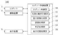
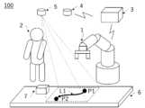
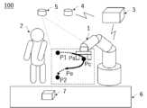
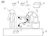
図1はロボット制御システム100を示す概略構成図である。ロボット制御システム100は、ロボット1、ロボット1の動作を制御するロボット制御装置3、ロボット1の動作領域にある作業者2等の人や物体を検出する撮像装置4、後述するロボット動作情報を実作業空間に表示する表示装置5を備える。
1 is a schematic diagram showing a
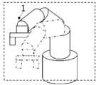
ロボット1は、例えば6軸の垂直多関節型ロボットであり、各軸に搭載されたモータにより、各軸のアームが駆動する。ロボット1には図示しないエンコーダが備えられ、エンコーダはモータの現在の回転角度を計測する。例えば、ロボット1はベルトコンベア6に置かれたワーク7を把持し、移動させる等の作業を作業者と協働して行う。
ここでは、ロボット1がベルトコンベア6に置かれたワーク7に対し動作を行う例について説明するが、これに限られない。ベルトコンベア6以外の作業台等の周辺装置があってもよいし、ワーク7への動作ではなく他の動作を行ってもよい。Here, an example will be described in which the
作業者2は、ロボット1と同じ作業空間で作業を行う協働作業者である。作業者2はロボット1の動作領域を含む作業空間でワーク7に対し作業を行う。撮像装置4は、ロボット1の動作領域を含む領域を検出する。すなわち、撮像装置4は、ロボットの周囲に存在する人および物体を検出する検出装置であり、撮像装置4で撮像した撮像情報は検出信号である。
ロボット制御装置3は制御プログラムを先読みし、ロボット1のアームやエンドエフェクタの位置を参照したロボット1の動作開始位置、現在位置、目的位置、動作経路(軌跡)、動作方向、動作速度、等のロボット動作情報を算出する。ここで、制御プログラムに規定されたロボット1の動作に関する情報をロボット動作情報とする。またロボット制御装置3は、各軸のアームの長さや回転方向を持つロボットモデルを有しており、ロボット1のエンコーダから送られるモータの回転角度を取得することで、エンドエフェクタの現在フィードバック位置、現在フィードバック姿勢、現在フィードバック速度等を計算する。ロボット制御装置3は、作業者2にロボット動作情報を示す画像を生成し表示装置5に送信する。The
表示装置5は、例えばプロジェクタでありロボット制御装置3と無線または有線で接続される。表示装置5は、ロボット制御装置3から受信したロボット動作情報を示す画像を作業空間上に表示する。図1では、点線で囲まれた部分が表示画像である。表示画像は、エンドエフェクタの動作開始位置P1、現在位置Pc、目的位置P2、動作経路L1、動作方向等を含む。動作方向は矢印で表現されている。動作開始位置P1、現在位置Pc、目的位置P2、動作経路L1、動作方向、動作速度は、ロボット動作情報である。動作経路L1は動作開始位置P1から目的位置P2の間の動作軌跡である。The
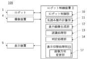
図2は、実施の形態1にかかるロボット制御システム100の機能ブロック図である。ロボット制御装置3は、ロボット制御部10、先読み動作計算部11、表示画像生成部12、認識処理部13、判定処理部14、表示切替処理部15を備える。2 is a functional block diagram of the
先読み動作計算部11は、制御プログラムを先読みし、目的位置P2および動作補間の種類を取得する。動作補間の種類は、エンドエフェクタを直線上に動作させる補間、円弧上を動作させる補間、あらかじめ設定された自由曲線上を動作させる補間等があり、その他の補間方法を指定することも可能である。The look-ahead
先読み動作計算部11は、制御プログラムの目的位置P2および動作補間の種類から、各時刻t毎のエンドエフェクタの指令位置P(t)を計算することで補間処理を行う。先読み動作計算部11は、指令位置P(t)をもとに動作経路L1を算出する。先読み動作計算部11は、ロボット動作情報として、動作経路L1、動作開始位置P1、目的位置P2、現在位置Pc、動作速度等を計算し、表示画像生成部12、認識処理部13およびロボット制御部10に送信する。ここで動作開始位置P1は、目的位置P2までの補間が開始される位置またはロボットの停止中の位置から得られる位置である。The look-ahead
ロボット制御部10は、先読み動作計算部11から取得したロボット動作情報に基づき、ロボット1の各軸のモータを駆動させることでロボット1の動きを制御する。The
認識処理部13は、撮像装置4から撮像情報を受信し、工作機械、構造物、ワーク7等の物体および作業者2等の人の位置や動きを含む情報を取得する。認識処理部13は、撮像情報に人が含まれるか否かを認識する。また、人が含まれる場合どの位置に人がいるか、人がどのような動き(例えば動作方向、動作速度等)をしているか等を撮像情報に基づき解析する。また認識処理部13は、どの位置に物体があるか等を解析する。例えば、工作機械や構造物等の物体や人のモデル画像をあらかじめ登録しておき、撮像情報とモデル画像とを照合することで解析する。認識処理部13は、解析結果を判定処理部14に送信する。The
判定処理部14は、先読み動作計算部11から受信したロボット動作情報、および認識処理部13の解析結果に基づき、人とロボット1が接近しているか否かを判定する。人とロボット1が接近しているか否かの判定は、例えば、人とロボット1の時間ごとの相対距離を算出し、相対距離が時間経過に従い短くなっていれば、接近していると判定する。判定処理部14は、判定結果を表示切替処理部15に送信する。The
表示画像生成部12は、先読み動作計算部11から得たロボット動作情報から、ロボット動作情報を示す表示画像を生成し、表示切替処理部15に送信する。図1の例では、動作開始位置P1、現在位置Pc、目的位置P2、動作経路L1の表示画像を生成する。The display
表示切替処理部15は、判定処理部14の判定結果に基づき、表示画像を切り替える。表示切替処理部15は、認識処理部13が人を含むと認識した場合と、人を含まないと認識した場合で表示画像を切り替える。具体的には、判定処理部14により人がロボット1の動作方向に接近していると判定されれば、表示画像生成部12から受信した表示画像に警告を追加等することで表示画像を変更し、変更後の表示画像を表示装置5に送信する。The display
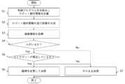
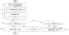
図3は、実施の形態1にかかるロボット制御装置3が行う処理のフローチャートである。まず、ロボット制御装置3の先読み動作計算部11は、制御プログラムを先読みしてロボット動作情報を計算し、表示画像生成部12に送信する(ステップS1)。次に、表示画像生成部12は、ロボット動作情報に基づき表示画像を生成し、表示切替処理部15に送信する(ステップS2)。次に、認識処理部13は、撮像装置4が撮像した撮像情報を取得する(ステップS3)。Figure 3 is a flowchart of the processing performed by the
次に、認識処理部13は、撮像情報から、どの位置に物体があるか、人がいるか、人がいる場合にはどの位置にいるのか、人の動作方向および動作速度等を解析し、解析結果を判定処理部14に送信する(ステップS4)。人がいる場合(ステップS4 Yes)、ステップS5に進み、人がいない場合(ステップS4 No)、ステップS7に進む。判定処理部14は、受信した解析結果から、人とロボット1が接近しているか否かを判定し、表示切替処理部15に結果を送信する(ステップS5)。Next, the
人とロボット1が接近している場合(ステップS5 Yes)、表示切替処理部15は、表示画像に警告の追加等の変更を加えた表示画像を表示装置5に送信する(ステップS6)。具体的な変更内容は、例えば、警告を追加する、文字の大きさを変える等であり、警告以外の表示画像が警告と干渉する場合は警告を優先して表示する。人とロボット1が接近していない場合(ステップS5 No)、表示切替処理部15は、表示画像生成部12から受信した表示画像をそのまま表示装置5に送信する(ステップS7)。If the person and the
ここで、ステップS1およびステップS2と、ステップS3およびステップS4の順序はこれに限られない。ステップS3およびステップS4が、ステップS1およびステップS2の前であってもよい。Here, the order of steps S1 and S2 and steps S3 and S4 is not limited to this. Steps S3 and S4 may be performed before steps S1 and S2.
図4に点線で示す表示画像は、図1に示す表示画像を表示切替処理部15によって変更した例である。例えば表示切替処理部15は、警告を表す文字20および警告を示すマーク21を追加し、文字「P1」、「Pc」の大きさを警告を表す文字20より小さくし、優先順位の低い文字「P2」、「L1」、および矢印を削除する変更を行っている。The display image indicated by the dotted line in Figure 4 is an example of the display image shown in Figure 1 modified by the display switching
図5は、ロボット制御装置3を実現するためのハードウェア構成図である。図5に示すとおり、上記ロボット制御装置3の一部又は全部は、具体的には、CPU31(Central Processing Unit)、記憶装置32、IO(INPUT OUTPUT:入出力)インターフェース33等により構成される。Figure 5 is a hardware configuration diagram for realizing the
記憶装置32はROM(Read Only Memory)、HDD(Hard Disk Drive)等から構成される。ロボット制御装置3のIOインターフェース33には、撮像装置4、表示装置5、ロボット1が無線または有線で接続される。記憶装置32には、制御プログラム、認識処理部13で用いる工作機械、構造物等の物体や人のモデル画像、ロボット1のアームモデル等が保存されている。ロボット制御装置3の一連の処理は、記憶装置32に保存されている制御プログラムをCPU31が実行することで実現される。The
このように、本実施の形態によれば、撮像装置4でロボット1の周囲の状況を取得し、人がいるか否かを検出し、人がいる場合にはロボット動作情報および人の動きに基づいて人とロボット1が近づいているか否かを判定処理部14で判定する。人が近づいている(危険が予想される)場合には、表示画像生成部12で生成した画像に警告を追加する等画像を変更して表示するので、人の安全に関わるロボットの動作を人にわかりやすく表示することができる。Thus, according to this embodiment, the
なお、ロボット制御システム100が撮像装置4を備える場合について述べたが、撮像装置4の代わりに距離センサ、視覚センサ、赤外線センサ、位置受信機を用いてもよい。位置受信機を用いる場合には、作業者2は位置送信機を所持して作業を行えばよい。位置受信機が作業者2の位置送信機から位置を受信すると、認識処理部13でその位置に人がいると認識できる。この場合にも上述と同様の効果を奏する。Although the
また、認識処理部13が、あらかじめ登録された画像とのマッチングを行うことで解析を行う例を示したが、取得した撮像情報の時刻毎の変化量から人と物体を識別してもよい。撮像装置4の代わりに距離センサ、視覚センサ等を用いる場合には、取得したセンサ情報の時刻毎の変化量から人と物体を識別する。撮像装置4の代わりに赤外線センサを用いた場合には、人の体温に対応する閾値をあらかじめ登録しておき、センサ出力が閾値を超えた場合に人であると認識処理部13に認識させればよい。これらの場合にも上述と同様の効果を奏する。Although an example has been shown in which the
また、図3のステップS7で、人とロボットが接近していない場合に表示画像をそのまま送信する例を示したが、人とロボットが接近している場合(ステップS6)の変更と異なる変更を行ってもよい。その場合には、人に注意を向けさせるステップS6の変更よりも目立たない変更を行う。具体的には色を目立たなくする、字を小さくする等の変更を行う。In addition, in step S7 of FIG. 3, an example was shown in which the display image is sent as is when the person and the robot are not in close proximity, but changes different from those made when the person and the robot are in close proximity (step S6) may be made. In that case, changes that are less noticeable than the changes made in step S6 to draw the person's attention are made. Specifically, changes are made such as making the colors less noticeable or making the text smaller.
また、ロボット動作情報として、動作開始位置P1、現在位置Pc、目的位置P2、動作経路L1、動作方向を表示させたが、ロボット1の姿勢をロボット動作情報として表示させてもよい。図6は、ロボット動作情報をロボット1の姿勢とした表示画像の一例である。この場合、表示画像生成部12は、アームモデルを用いて一定時間後のロボットの姿勢を生成する。このようにすると、ロボット動作情報を人に立体的に認識させることができる。つまり、人の安全に関わるロボットの動作を、よりわかりやすく表示できる。In addition, while the operation start position P1, current position Pc, destination position P2, operation path L1, and operation direction are displayed as the robot operation information, the posture of the
また、表示装置5が空間上に画像を表示させる例について説明したが、表示装置5がプロジェクタであれば投影面を決めて画像を表示させてもよい。図7は、投影面をベルトコンベア6とした例である。Although an example in which the
また、表示装置5をヘッドマウントディスプレイとしてもよいし、LEDディスプレイとしてもよい。図8は、ロボット1の台座に表示装置5であるLEDディスプレイを組み込んだ例である。ロボット動作情報として、動作方向を図形で、動作速度を文字で表示している。The
また、ロボット1が停止中の場合、警告の追加に加えロボット1が停止中である旨の表示をしてもよい。図9はロボット1が停止中であることを表示させた例である。実際の作業では、ロボット1を一時停止し、再始動により動作を途中から行う場合がある。人がロボット1の動作範囲内にいると、再始動したときにロボット1と衝突したり、人がロボット1の動作に驚いて転倒したりする可能性がある。そのため、停止中であること、および、再始動後の動作軌跡を表示することで、停止中であっても再始動時のロボット1の動作であって、人の安全に関わる動作を人に知らせることができる。Furthermore, when the
また、作業者2を人の例として説明したが、指令者、見学者等の作業者2以外の人を検出して、同様の操作をすることも可能である。Although the
実施の形態2.
図10は実施の形態2にかかるロボット制御システム100を示す機能ブロック図である。実施の形態1と同じ箇所は説明を省略する。
10 is a functional block diagram showing a
図10に基づき、実施の形態2にかかるロボット制御システム100について説明する。実施の形態2のロボット制御システム100は、実施の形態1のロボット制御システム100に対し、判定処理部14が衝突判定部16となる点が異なる。その他は、実施の形態1と同様である。A
認識処理部13は、撮像情報から、人がいるか、どの位置に人がいるか、どの位置に物体があるか、人または物体の速度等を解析し、結果を衝突判定部16に送信する。衝突判定部16は、先読み動作計算部11から受信したロボット動作情報、および認識処理部13の解析結果に基づいて、人または物体がロボット1と衝突するか否かを判定する。衝突判定部16は、判定結果を表示切替処理部15に送信する。The
図11は、実施の形態2にかかるロボット制御装置3が行う処理のフローチャートである。図3のフローチャートと比べると、ステップS5およびステップS6がなく、ステップS8からステップS11が追加されている点が異なり、その他は同様である。図3と同様の箇所は説明を省略する。Figure 11 is a flowchart of the processing performed by the
まず、ステップS4がYesの場合、衝突判定部16は認識処理部13の解析結果から、人がロボット1と衝突するか否かを判定する(ステップS8)。衝突すると判定された場合(ステップS8 Yes)、表示切替処理部15は、表示画像に警告を追加して表示装置5に送信する(ステップS10)。衝突しない場合(ステップS8 No)、表示切替処理部15は表示画像をそのまま送信する(ステップS7)。First, if step S4 is Yes, the
ステップS4で人がいると判定されない場合(ステップS4 No)、衝突判定部16は認識処理部13の解析結果から、物体がロボット1と衝突するか否かを判定する(ステップS9)。物体がロボット1と衝突する場合(ステップS9 Yes)、表示切替処理部15は、ステップS10の警告より目立たない態様で表示画像に警告を追加して表示装置5に送信する(ステップS11)。衝突しない場合(ステップS9 No)、表示切替処理部15は表示画像をそのまま送信する(ステップS7)。If it is not determined in step S4 that a person is present (step S4 No), the
ステップS10では、例えば、警告に用いる線の太さを、物体とロボット1が衝突した場合の警告に用いる線の太さより太くしたり、文字の大きさを大きくしたり、色をステップS11の警告とは異なる色にして、警告を目立たせる。ここで、ステップS10では、画像の変更だけでなく音を発生させてもよい。In step S10, the warning is made more noticeable by, for example, making the line thickness used for the warning thicker than the line thickness used for the warning when the object collides with the
このように本実施の形態によれば、回避行動をとらなければ人がロボット1と衝突しそうな場合に、表示切替処理部15が、物体がロボット1と衝突する場合よりも目立つ態様で警告を追加する。これにより、回避行動をとらなければ人と衝突してしまうという安全上影響が大きいロボット1の動作を、作業者2が把握しやすくなる。Thus, according to this embodiment, when a person is likely to collide with the
ロボット1と作業者2の協働作業中には、作業者2が作業していたワーク7をロボット1の動作軌跡上に置いてしまうことがある。本実施の形態によれば、物体がロボット1と衝突しそうな場合に表示切替処理部15が警告を追加するので、このような場合でも、作業者2が、ワーク7の衝突前にワーク7を取り除く等の対処をさせることができる。すなわち、作業を一時的に停止することなく、物体とロボット1との干渉が防げるので作業効率が向上する。When the
なお、本実施の形態において実施の形態1の判定処理部14の代わりに衝突判定部16を備えたが、判定処理部14に加え衝突判定部16があってもよい。その場合には、人が衝突すると判定された場合、表示切替処理部15は、人が接近している場合の警告よりも目立つ態様で警告を追加して表示する。これにより、人の安全に関わるロボット1の動作について、安全に関わるレベルを分けて作業者に知らせることができる。In this embodiment, a
実施の形態3.
図12は、実施の形態3にかかるロボット制御システム100を示す機能ブロック図である。図12に基づき、実施の形態3にかかるロボット制御システム100について説明する。実施の形態3では、実施の形態1の表示切替処理部15に画像方向変更部17が追加されている点が異なり、その他の構成は同様である。実施の形態1と同じ箇所は説明を省略する。
Fig. 12 is a functional block diagram showing a
画像方向変更部17は、認識処理部13から人の位置を取得する。画像方向変更部17は、取得した位置から見やすくなるよう、警告等追加した表示画像をさらに変更する。すなわち、画像方向変更部17は、人の位置によって表示画像の向きを変更する。図13は、画像方向変更部17により文字方向を変更した一例である。表示画像生成部12が作成した表示画像の文字を作業者2の位置が正面になるよう回転させる変更を行っている。The image
このようにすれば、作業者2に表示画像を把握させやすくなるので、人の安全に関わるロボットの動作をより把握しやすくできる。This makes it easier for
なお、実施の形態1のロボット制御システム100の表示切替処理部15に画像方向変更部17を追加させる例について説明したが、同様に実施の形態2のロボット制御システム100に追加させてもよい。この場合にも人の安全に関わるロボット1の動作をより把握しやすくできる。Although an example of adding the image
実施の形態4.
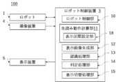
図14は、実施の形態4にかかるロボット制御システム100を示す機能ブロック図である。図14に基づき、実施の形態4にかかるロボット制御システム100について説明する。実施の形態4のロボット制御システム100は、実施の形態1における先読み動作計算部11に表示区間設定部18を備える点が異なり、その他の構成は同様である。実施の形態1と同じ箇所は説明を省略する。
Fig. 14 is a functional block diagram showing a
先読み動作計算部11は、表示画像の表示区間を取得する表示区間設定部18を有する。表示区間設定部18は、図示しないROM等の記憶装置32を有し、作業者2からあらかじめ取得した表示区間を記憶装置32に記憶させる。図15は、表示区間を説明する図である。図15において、現在位置はPc、現在時刻はTc、動作開始位置はP1、開始時刻はT1、目的位置はP2、目的位置に対応する時刻はT2である。現在時刻Tcを起点に過去表示区間Tsだけ過去の時刻Tc-Tsから、現在時刻Tcを起点に未来表示区間Teだけ未来の時刻Tc+Teまでが表示区間である。表示区間設定部18は、過去表示区間Tsおよび未来表示区間Teを記憶装置32に記憶させる。The look-ahead
先読み動作計算部11は、過去表示区間Ts、未来表示区間Teを用いて、時刻Tc-Tsに対応する変更表示開始位置Ps、時刻Tc+Teに対応する変更表示終了位置Pe、および変更表示開始位置Psから変更表示終了位置Peまでのロボット1の動作軌跡をロボット動作情報として算出し、表示画像生成部12に送信する。先読み動作計算部11は、現在時刻Tcから未来表示区間Teの時間未来に到る時刻(Tc+Te)に対応するロボット1の位置をロボット動作情報として算出する。The look-ahead
表示画像生成部12は、現在時刻Tcから未来表示区間Te分未来の時刻(Tc+Te)に対応するロボット1の位置を含む表示画像を生成する。The display
図16は、実施の形態4にかかる表示画像生成部12により表示区間を変更した一例である。表示画像は、動作開始位置P1、現在位置Pc、動作経路L1、動作開始位置P1と現在位置Pcの間の軌跡上にある変更表示開始位置Ps、現在位置Pcと目的位置P2の間の軌跡上にある変更表示終了位置Pe、変更表示開始位置Psから変更表示終了位置Peまでの動作軌跡、動作方向を含んでいる。Figure 16 is an example in which the display section is changed by the display
図17、図18は、実施の形態4にかかるロボット制御システム100における表示区間の設定例である。図17は、図18よりも表示区間を長く設定している。表示区間の長さは作業者2に応じて決定する。例えば、作業者2が初心者の場合、作業者2はロボットの動作を予測することが難しいため、表示区間を長くする。逆に作業者2が熟練者の場合、作業者2はロボットの動作を予測することができるので、表示区間を短くする。図18の例では、変更表示開始位置Psは現在位置Pcと同じ位置としている。Figures 17 and 18 are examples of display interval settings in the
このように、本実施の形態では、表示区間設定部18で表示区間を設定できるようにしたので、例えば作業者2の熟練度に応じて表示区間の変更が可能となる。表示区間を長くすることで、ロボット1の動作の予測が難しい作業者2でもロボットの動作を把握でき、安全性が向上する。また、表示区間を短くすることで、作業者2が作業に集中でき作業効率を向上させることができる。In this way, in this embodiment, the display interval can be set by the display
なお、ここでは過去表示区間Tsおよび未来表示区間Teを取得する例について説明したが、過去表示区間Tsと未来表示区間Teを同一の値とし、1つの値を取得してもよい。過去表示区間Tsを固定値とし、未来表示区間Teのみ取得してもよい。これらの場合も上述と同様の効果を奏する。Note that, although an example of acquiring the past display section Ts and the future display section Te has been described here, the past display section Ts and the future display section Te may be set to the same value and a single value may be acquired. The past display section Ts may be set to a fixed value and only the future display section Te may be acquired. In these cases, the same effect as described above is achieved.
また、実施の形態1のロボット制御システム100の先読み動作計算部11に表示区間設定部18を備える例について説明したが、実施の形態2、実施の形態3のロボット制御システム100に備えてもよい。これらの場合も上述と同様の効果を奏する。Although an example in which the look-ahead
以上の実施の形態に示した構成は、本開示の内容の一例を示すものであり、別の公知の技術と組み合わせることも可能であるし、上記の実施の形態の組み合わせや、本開示の要旨を逸脱しない範囲で、構成の一部を省略、変更することも可能である。The configurations shown in the above embodiments are examples of the contents of the present disclosure, and may be combined with other known technologies. It is also possible to combine the above embodiments, or omit or modify parts of the configurations without departing from the gist of the present disclosure.
1 ロボット、2 作業者、3 ロボット制御装置、4 撮像装置、5 表示装置、6 ベルトコンベア、7 ワーク、10 ロボット制御部、11 先読み動作計算部、12 表示画像生成部、13 認識処理部、14 判定処理部、15 表示切替処理部、16 衝突判定部、17 画像方向変更部、100 ロボット制御システム。1 Robot, 2 Worker, 3 Robot control device, 4 Imaging device, 5 Display device, 6 Conveyor belt, 7 Work, 10 Robot control unit, 11 Look-ahead operation calculation unit, 12 Display image generation unit, 13 Recognition processing unit, 14 Judgment processing unit, 15 Display switching processing unit, 16 Collision judgment unit, 17 Image direction change unit, 100 Robot control system.
Claims (5)
Translated fromJapaneseユーザの設定により変更可能な表示区間を記憶装置に記憶する表示区間設定部を有し、前記制御プログラムを先読みし、前記制御プログラムに規定されたロボットの動作を示すロボット動作情報を算出する先読み動作計算部と、
前記ロボット動作情報を示す表示画像であって、前記表示区間に対応した前記ロボットの位置を含む前記表示画像を生成する表示画像生成部と、
前記ロボットの動作領域内の人および物体を検出する検出装置から受信した検出信号に人が含まれるか否かを認識する認識処理部と、
前記認識処理部が人を含むと認識した場合は、前記表示画像に警告表示を追加し、人を含まないと認識した場合は、前記表示画像に警告表示を追加しない表示切替処理部と、
を備え、
前記表示切替処理部は、回避行動をとらなければ前記認識処理部により前記検出信号に含まれると認識された人が前記ロボットと衝突しそうな場合に、前記物体が前記ロボットと衝突する場合よりも目立つ態様で前記警告表示を追加する、
ロボット制御装置。 A robot control device that operates according to a control program,
a display section setting unit that stores a display section that can be changed by a user in a storage device, and a look-ahead motion calculation unit that looks ahead at the control program and calculates robot motion information that indicates a robot motion defined in the control program;
a display image generating unit that generates a display image showing the robot operation information, the display image including a position of the robot corresponding to the display section;
a recognition processing unit that recognizes whether a person is included in a detection signal received from a detection device that detects people and objects within an operating area of the robot;
a display switching processing unit that adds a warning display to the display image when the recognition processing unit recognizes that the display image includes a person, and does not add a warning display to the display image when the recognition processing unit recognizes that the display image does not include a person;
Equipped with
the display switching processing unit, when a person recognized by the recognition processing unit as being included in the detection signal is likely to collide with the robot unless an avoidance action is taken, adds the warning display in a more conspicuous manner than when the object is to collide with the robot.
Robot control device.
前記表示切替処理部は、前記人の位置によって前記表示画像の向きを変更する画像方向変更部を有することを特徴とする請求項1に記載のロボット制御装置。 The recognition processing unit analyzes a position of the person,
The robot control device according to claim 1 , wherein the display switching processing unit includes an image direction changing unit that changes the direction of the display image depending on the position of the person.
前記ロボット制御装置により制御されるロボットと、
前記ロボットの動作領域を含む領域を検出する検出装置と、
前記ロボット制御装置から表示画像を受信し表示する表示装置と
を備えるロボット制御システム。 A robot control device according to any one of claims 1 to 3,
a robot controlled by the robot control device;
A detection device for detecting an area including a motion area of the robot;
A robot control system comprising a display device that receives and displays a display image from the robot control device.
制御プログラムを先読みし、前記制御プログラムに規定されたロボットの動作を示すロボット動作情報を算出するステップと、
前記ロボット動作情報を示す表示画像であって、前記表示区間に対応した前記ロボットの位置を含む前記表示画像を生成するステップと、
前記ロボットの動作領域内の人および物体を検出する検出装置から受信した検出信号に人が含まれるか否かを認識する認識ステップと、
人を含むと認識した場合は、前記表示画像に警告表示を追加し、人を含まないと認識した場合は、前記表示画像に警告表示を追加しない表示切替ステップと
を含み、
前記表示切替ステップは、回避行動をとらなければ前記認識ステップにおいて前記検出信号に含まれると認識された人が前記ロボットと衝突しそうな場合に、前記物体が前記ロボットと衝突する場合よりも目立つ態様で前記警告表示を追加する、
ロボット制御方法。 storing a display section that can be changed by a user in a storage device;
A step of reading ahead a control program and calculating robot operation information indicating a robot operation defined in the control program;
generating a display image showing the robot operation information, the display image including a position of the robot corresponding to the display section;
a recognition step of recognizing whether a person is included in a detection signal received from a detection device that detects people and objects within an operating area of the robot;
a display switching step of adding a warning display to the display image when it is recognized that the display image includes a person, and not adding a warning display to the display image when it is recognized that the display image does not include a person,
the display switching step adds the warning display in a more conspicuous manner than in a case where the object collides with the robot, when the person recognized in the recognition step as being included in the detection signal is likely to collide with the robot unless an avoidance action is taken;
A method for controlling a robot.
Applications Claiming Priority (1)
| Application Number | Priority Date | Filing Date | Title |
|---|---|---|---|
| PCT/JP2023/004112WO2024166238A1 (en) | 2023-02-08 | 2023-02-08 | Robot control device, robot control system, and robot control method |
Publications (3)
| Publication Number | Publication Date |
|---|---|
| JPWO2024166238A1 JPWO2024166238A1 (en) | 2024-08-15 |
| JP7589833B1true JP7589833B1 (en) | 2024-11-26 |
| JPWO2024166238A5 JPWO2024166238A5 (en) | 2025-01-15 |
Family
ID=92262159
Family Applications (1)
| Application Number | Title | Priority Date | Filing Date |
|---|---|---|---|
| JP2023563279AActiveJP7589833B1 (en) | 2023-02-08 | 2023-02-08 | ROBOT CONTROL DEVICE, ROBOT CONTROL SYSTEM, AND ROBOT CONTROL METHOD |
Country Status (2)
| Country | Link |
|---|---|
| JP (1) | JP7589833B1 (en) |
| WO (1) | WO2024166238A1 (en) |
Citations (7)
| Publication number | Priority date | Publication date | Assignee | Title |
|---|---|---|---|---|
| WO2011089885A1 (en)* | 2010-01-25 | 2011-07-28 | パナソニック株式会社 | Danger presentation device, danger presentation system, danger presentation method, and program |
| JP2018051653A (en)* | 2016-09-27 | 2018-04-05 | 株式会社デンソーウェーブ | Display system for robot |
| US20190299412A1 (en)* | 2018-03-29 | 2019-10-03 | Sick Ag | Augmented Reality System |
| JP2019188531A (en)* | 2018-04-25 | 2019-10-31 | ファナック株式会社 | Simulation device of robot |
| JP2021024028A (en)* | 2019-08-05 | 2021-02-22 | キヤノン株式会社 | Information processing device, control method of information processing device, and manufacturing method of article |
| WO2021095316A1 (en)* | 2019-11-11 | 2021-05-20 | 株式会社日立製作所 | Robot system |
| JP2021084218A (en)* | 2019-11-29 | 2021-06-03 | オムロン株式会社 | Information presentation device, information presentation method, and information presentation program |
- 2023
- 2023-02-08JPJP2023563279Apatent/JP7589833B1/enactiveActive
- 2023-02-08WOPCT/JP2023/004112patent/WO2024166238A1/enactivePending
Patent Citations (7)
| Publication number | Priority date | Publication date | Assignee | Title |
|---|---|---|---|---|
| WO2011089885A1 (en)* | 2010-01-25 | 2011-07-28 | パナソニック株式会社 | Danger presentation device, danger presentation system, danger presentation method, and program |
| JP2018051653A (en)* | 2016-09-27 | 2018-04-05 | 株式会社デンソーウェーブ | Display system for robot |
| US20190299412A1 (en)* | 2018-03-29 | 2019-10-03 | Sick Ag | Augmented Reality System |
| JP2019188531A (en)* | 2018-04-25 | 2019-10-31 | ファナック株式会社 | Simulation device of robot |
| JP2021024028A (en)* | 2019-08-05 | 2021-02-22 | キヤノン株式会社 | Information processing device, control method of information processing device, and manufacturing method of article |
| WO2021095316A1 (en)* | 2019-11-11 | 2021-05-20 | 株式会社日立製作所 | Robot system |
| JP2021084218A (en)* | 2019-11-29 | 2021-06-03 | オムロン株式会社 | Information presentation device, information presentation method, and information presentation program |
Also Published As
| Publication number | Publication date |
|---|---|
| WO2024166238A1 (en) | 2024-08-15 |
| JPWO2024166238A1 (en) | 2024-08-15 |
Similar Documents
| Publication | Publication Date | Title |
|---|---|---|
| US11207777B2 (en) | Robot controlling device and automatic assembling system | |
| JP5987842B2 (en) | Communication pull-in system, communication pull-in method and communication pull-in program | |
| JP5059978B2 (en) | Danger presentation device, danger presentation system, danger presentation method and program | |
| JP6420229B2 (en) | A robot system including a video display device that superimposes and displays an image of a virtual object on a video of a robot | |
| US10427298B2 (en) | Robot system displaying information for teaching robot | |
| JP7000364B2 (en) | Robot system | |
| JP2009123045A (en) | MOBILE ROBOT AND METHOD FOR DISPLAYING HAZARD RANGE OF MOBILE ROBOT | |
| JP6801333B2 (en) | Display system for robots | |
| US7653458B2 (en) | Robot device, movement method of robot device, and program | |
| JP2008229800A (en) | Arm-mounted mobile robot and its control method | |
| JP2018176342A (en) | Robot system and operating method thereof | |
| JP2016209991A (en) | Robot control device, controlling method, and program | |
| JP6823018B2 (en) | Coordination support device | |
| JP2016196069A (en) | Avoidance trajectory generation apparatus and avoidance trajectory generation method for industrial robot | |
| CN119501929A (en) | A robot teleoperation method and system based on virtual reality and digital twin | |
| JP7589833B1 (en) | ROBOT CONTROL DEVICE, ROBOT CONTROL SYSTEM, AND ROBOT CONTROL METHOD | |
| JP7079435B2 (en) | Robot control device, robot control method and robot control program | |
| JP7282016B2 (en) | robot system | |
| JP6885909B2 (en) | Robot control device | |
| WO2020067445A1 (en) | Control device | |
| JP2020001137A (en) | Robot controller and robot system | |
| JP6965981B2 (en) | Display system for robots | |
| US11752629B2 (en) | Scanner controller and scanner control system | |
| KR102681939B1 (en) | robot system | |
| CN113396031A (en) | Force-limited travel of at least one element of a production machine in manual operation |
Legal Events
| Date | Code | Title | Description |
|---|---|---|---|
| A521 | Request for written amendment filed | Free format text:JAPANESE INTERMEDIATE CODE: A523 Effective date:20231016 | |
| A621 | Written request for application examination | Free format text:JAPANESE INTERMEDIATE CODE: A621 Effective date:20231016 | |
| A871 | Explanation of circumstances concerning accelerated examination | Free format text:JAPANESE INTERMEDIATE CODE: A871 Effective date:20231016 | |
| A131 | Notification of reasons for refusal | Free format text:JAPANESE INTERMEDIATE CODE: A131 Effective date:20240123 | |
| A521 | Request for written amendment filed | Free format text:JAPANESE INTERMEDIATE CODE: A523 Effective date:20240228 | |
| A131 | Notification of reasons for refusal | Free format text:JAPANESE INTERMEDIATE CODE: A131 Effective date:20240514 | |
| A521 | Request for written amendment filed | Free format text:JAPANESE INTERMEDIATE CODE: A523 Effective date:20240621 | |
| RD01 | Notification of change of attorney | Free format text:JAPANESE INTERMEDIATE CODE: A7421 Effective date:20240704 | |
| TRDD | Decision of grant or rejection written | ||
| A01 | Written decision to grant a patent or to grant a registration (utility model) | Free format text:JAPANESE INTERMEDIATE CODE: A01 Effective date:20241015 | |
| A61 | First payment of annual fees (during grant procedure) | Free format text:JAPANESE INTERMEDIATE CODE: A61 Effective date:20241028 | |
| R150 | Certificate of patent or registration of utility model | Ref document number:7589833 Country of ref document:JP Free format text:JAPANESE INTERMEDIATE CODE: R150 |