JP7589424B2 - Multi-directional input device - Google Patents
Multi-directional input deviceDownload PDFInfo
- Publication number
- JP7589424B2 JP7589424B2JP2024505982AJP2024505982AJP7589424B2JP 7589424 B2JP7589424 B2JP 7589424B2JP 2024505982 AJP2024505982 AJP 2024505982AJP 2024505982 AJP2024505982 AJP 2024505982AJP 7589424 B2JP7589424 B2JP 7589424B2
- Authority
- JP
- Japan
- Prior art keywords
- strain
- cylindrical portion
- generating body
- substrate
- input device
- Prior art date
- Legal status (The legal status is an assumption and is not a legal conclusion. Google has not performed a legal analysis and makes no representation as to the accuracy of the status listed.)
- Active
Links
Images


Classifications
- G—PHYSICS
- G05—CONTROLLING; REGULATING
- G05G—CONTROL DEVICES OR SYSTEMS INSOFAR AS CHARACTERISED BY MECHANICAL FEATURES ONLY
- G05G25/00—Other details or appurtenances of control mechanisms, e.g. supporting intermediate members elastically
- G—PHYSICS
- G05—CONTROLLING; REGULATING
- G05G—CONTROL DEVICES OR SYSTEMS INSOFAR AS CHARACTERISED BY MECHANICAL FEATURES ONLY
- G05G9/00—Manually-actuated control mechanisms provided with one single controlling member co-operating with two or more controlled members, e.g. selectively, simultaneously
- G05G9/02—Manually-actuated control mechanisms provided with one single controlling member co-operating with two or more controlled members, e.g. selectively, simultaneously the controlling member being movable in different independent ways, movement in each individual way actuating one controlled member only
- G05G9/04—Manually-actuated control mechanisms provided with one single controlling member co-operating with two or more controlled members, e.g. selectively, simultaneously the controlling member being movable in different independent ways, movement in each individual way actuating one controlled member only in which movement in two or more ways can occur simultaneously
- G05G9/047—Manually-actuated control mechanisms provided with one single controlling member co-operating with two or more controlled members, e.g. selectively, simultaneously the controlling member being movable in different independent ways, movement in each individual way actuating one controlled member only in which movement in two or more ways can occur simultaneously the controlling member being movable by hand about orthogonal axes, e.g. joysticks
- G—PHYSICS
- G06—COMPUTING OR CALCULATING; COUNTING
- G06F—ELECTRIC DIGITAL DATA PROCESSING
- G06F3/00—Input arrangements for transferring data to be processed into a form capable of being handled by the computer; Output arrangements for transferring data from processing unit to output unit, e.g. interface arrangements
- G06F3/01—Input arrangements or combined input and output arrangements for interaction between user and computer
- G06F3/03—Arrangements for converting the position or the displacement of a member into a coded form
- G06F3/033—Pointing devices displaced or positioned by the user, e.g. mice, trackballs, pens or joysticks; Accessories therefor
- G06F3/0338—Pointing devices displaced or positioned by the user, e.g. mice, trackballs, pens or joysticks; Accessories therefor with detection of limited linear or angular displacement of an operating part of the device from a neutral position, e.g. isotonic or isometric joysticks
- H—ELECTRICITY
- H01—ELECTRIC ELEMENTS
- H01H—ELECTRIC SWITCHES; RELAYS; SELECTORS; EMERGENCY PROTECTIVE DEVICES
- H01H13/00—Switches having rectilinearly-movable operating part or parts adapted for pushing or pulling in one direction only, e.g. push-button switch
- H—ELECTRICITY
- H01—ELECTRIC ELEMENTS
- H01H—ELECTRIC SWITCHES; RELAYS; SELECTORS; EMERGENCY PROTECTIVE DEVICES
- H01H25/00—Switches with compound movement of handle or other operating part
- H01H25/06—Operating part movable both angularly and rectilinearly, the rectilinear movement being along the axis of angular movement
- G—PHYSICS
- G05—CONTROLLING; REGULATING
- G05G—CONTROL DEVICES OR SYSTEMS INSOFAR AS CHARACTERISED BY MECHANICAL FEATURES ONLY
- G05G9/00—Manually-actuated control mechanisms provided with one single controlling member co-operating with two or more controlled members, e.g. selectively, simultaneously
- G05G9/02—Manually-actuated control mechanisms provided with one single controlling member co-operating with two or more controlled members, e.g. selectively, simultaneously the controlling member being movable in different independent ways, movement in each individual way actuating one controlled member only
- G05G9/04—Manually-actuated control mechanisms provided with one single controlling member co-operating with two or more controlled members, e.g. selectively, simultaneously the controlling member being movable in different independent ways, movement in each individual way actuating one controlled member only in which movement in two or more ways can occur simultaneously
- G05G9/047—Manually-actuated control mechanisms provided with one single controlling member co-operating with two or more controlled members, e.g. selectively, simultaneously the controlling member being movable in different independent ways, movement in each individual way actuating one controlled member only in which movement in two or more ways can occur simultaneously the controlling member being movable by hand about orthogonal axes, e.g. joysticks
- G05G2009/0474—Manually-actuated control mechanisms provided with one single controlling member co-operating with two or more controlled members, e.g. selectively, simultaneously the controlling member being movable in different independent ways, movement in each individual way actuating one controlled member only in which movement in two or more ways can occur simultaneously the controlling member being movable by hand about orthogonal axes, e.g. joysticks characterised by means converting mechanical movement into electric signals
- G05G2009/04744—Switches
- G—PHYSICS
- G05—CONTROLLING; REGULATING
- G05G—CONTROL DEVICES OR SYSTEMS INSOFAR AS CHARACTERISED BY MECHANICAL FEATURES ONLY
- G05G9/00—Manually-actuated control mechanisms provided with one single controlling member co-operating with two or more controlled members, e.g. selectively, simultaneously
- G05G9/02—Manually-actuated control mechanisms provided with one single controlling member co-operating with two or more controlled members, e.g. selectively, simultaneously the controlling member being movable in different independent ways, movement in each individual way actuating one controlled member only
- G05G9/04—Manually-actuated control mechanisms provided with one single controlling member co-operating with two or more controlled members, e.g. selectively, simultaneously the controlling member being movable in different independent ways, movement in each individual way actuating one controlled member only in which movement in two or more ways can occur simultaneously
- G05G9/047—Manually-actuated control mechanisms provided with one single controlling member co-operating with two or more controlled members, e.g. selectively, simultaneously the controlling member being movable in different independent ways, movement in each individual way actuating one controlled member only in which movement in two or more ways can occur simultaneously the controlling member being movable by hand about orthogonal axes, e.g. joysticks
- G05G2009/0474—Manually-actuated control mechanisms provided with one single controlling member co-operating with two or more controlled members, e.g. selectively, simultaneously the controlling member being movable in different independent ways, movement in each individual way actuating one controlled member only in which movement in two or more ways can occur simultaneously the controlling member being movable by hand about orthogonal axes, e.g. joysticks characterised by means converting mechanical movement into electric signals
- G05G2009/04762—Force transducer, e.g. strain gauge
Landscapes
- Engineering & Computer Science (AREA)
- Physics & Mathematics (AREA)
- General Physics & Mathematics (AREA)
- General Engineering & Computer Science (AREA)
- Theoretical Computer Science (AREA)
- Automation & Control Theory (AREA)
- Human Computer Interaction (AREA)
- Switches With Compound Operations (AREA)
- Mechanical Control Devices (AREA)
- Position Input By Displaying (AREA)
- Push-Button Switches (AREA)
Description
Translated fromJapanese本発明は、多方向入力装置に関する。The present invention relates to a multi-directional input device.
下記特許文献1には、操作子の操作方向及び操作量を操作子によって押圧されて変形する弾性板に設けた複数の歪検知体によって検出する多方向入力装置が開示されている。The following Patent Document 1 discloses a multi-directional input device that detects the direction and amount of operation of an operator using multiple strain detectors attached to an elastic plate that is deformed when pressed by the operator.
しかしながら、特許文献1の技術は、操作子の押圧操作を開始してから、操作子が弾性板を押圧するまでは、弾性板が変形しないため、複数の歪検知体による検出を行うことができず、すなわち、押圧操作を検出することができない。However, in the technology of Patent Document 1, the elastic plate does not deform from the time the pressing operation of the operator is started until the operator presses the elastic plate, so detection by multiple strain detectors cannot be performed, i.e., the pressing operation cannot be detected.
一実施形態に係る多方向入力装置は、傾倒操作および押圧操作が可能な多方向入力装置であって、筒状部と、筒状部の外側に設けられた変形部とを有する起歪体と、起歪体の筒状部の内部に設けられたプランジャーと、起歪体の変形部に設けられた歪検知素子と、起歪体の筒状部の底部に設けられた基板と、基板とプランジャーの底部との間に設けられた弾性部材とを備え、起歪体は、変形部の外側の端部で機器本体に固定され、基板は、起歪体に固定される。A multi-directional input device according to one embodiment is a multi-directional input device capable of tilting and pressing operations, and includes a strain-generating body having a cylindrical portion and a deformation portion provided on the outside of the cylindrical portion, a plunger provided inside the cylindrical portion of the strain-generating body, a strain detection element provided on the deformation portion of the strain-generating body, a substrate provided on the bottom of the cylindrical portion of the strain-generating body, and an elastic member provided between the substrate and the bottom of the plunger, with the strain-generating body being fixed to the device body at the outer end of the deformation portion, and the substrate being fixed to the strain-generating body.
一実施形態に係る多方向入力装置によれば、押圧操作の微量な荷重を高精度に検出することができる。According to one embodiment of the multi-directional input device, minute loads of pressing operations can be detected with high accuracy.
以下、一実施形態について説明する。なお、以降の説明では、便宜上、図中Z軸方向を、上下方向とし、図中X軸方向および図中Y軸方向を水平方向とする。An embodiment will be described below. For the sake of convenience, in the following description, the Z-axis direction in the figure is taken as the up-down direction, and the X-axis and Y-axis directions in the figure are taken as the horizontal directions.
〔第1実施形態〕
(多方向入力装置100の構成)
図1は、第1実施形態に係る多方向入力装置100の外観斜視図である。図2は、第1実施形態に係る多方向入力装置100の上面側を示す分解斜視図である。図3は、第1実施形態に係る多方向入力装置100の下面側を示す分解斜視図である。図4は、第1実施形態に係る多方向入力装置100の断面図である。図5は、第1実施形態に係る多方向入力装置100の断面斜視図である。 First Embodiment
(Configuration of multi-directional input device 100)
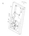
Fig. 1 is an external perspective view of the
図1~図5に示す多方向入力装置100は、ゲーム機、産業車両、ロボット操作等に用いられる、多方向(X軸方向、Y軸方向、およびこれらを組み合わせた方向)への傾倒操作、および、下方(Z軸負方向)への押圧操作が可能な入力装置である。図1~図5に示すように、多方向入力装置100は、キャップ102、起歪体120、荷重検出器130、基板160、弾性部材170、および機器本体110を備える。The
<キャップ102>
キャップ102は、起歪体120の筒状部125に取り付けられ、ユーザによる傾倒操作および押圧操作がなされる樹脂製の部材である。キャップ102は、上部が閉じ、且つ、下部が開口した円筒形状を有する。 <
The
キャップ102の筒内における中央には、上下方向(Z軸方向)に延びる棒状のプランジャー103がキャップ102と一体に設けられている。キャップ102は、起歪体120の筒状部125に取り付けられて、筒状部125の上部および外側を覆う。プランジャー103は、起歪体120の筒状部125の上部空間125A内に挿通される。なお、プランジャー103の外周面には、4方向に突出した、4つの突起103Aが設けられている。A rod-shaped
<起歪体120>
起歪体120は、キャップ102から操作荷重を受けて歪を発生する樹脂製の部材である。起歪体120は、筒状部125と、4つの変形部122とを有する。筒状部125は、起歪体120の中央に設けられており、上下方向(Z軸方向)を筒方向とする、円筒状の部分である。筒状部125の内部は、上部空間125Aと下部空間125Bとを有する。上部空間125Aは、筒状部125の内部の上側(Z軸正側)の部分である。上部空間125Aには、プランジャー103が挿通される。上部空間125Aの内径は、プランジャー103の外径と略同寸法である。下部空間125Bは、筒状部125の内部の下側(Z軸負側)の部分である。下部空間125Bは、上部空間125Aよりも内径が大きい。下部空間125Bには、基板160および弾性部材170が配置される。4つの変形部122は、筒状部125の下端部から、90°間隔で4つの方向に突出して設けられている。4つの変形部122の各々は、上下方向の厚みより平面方向の幅が広い板状である。 <
The
筒状部125の内周面には、4方向に設けられた4本の溝125Cが、上下方向(Z軸方向)に延在して設けられている。プランジャー103が有する4つの突起103Aの各々は、4本の溝125Cの各々の内部を上下方向にスライド可能である。Four
4つの変形部122の各々は、外側の端部に貫通穴122Aが形成されている。起歪体120は、4つの変形部122の各々の貫通穴122Aを上側(Z軸正側)から貫通する4本のネジ(図示省略)により、外側の端部が機器本体110にネジ止め固定される。Each of the four
なお、機器本体110は、変形部122の外側の端部と対向する位置に、平面部111から上方に突出して設けられた機器側突出部112を有する。4つの変形部122の各々の外側の端部は、機器本体110の機器側突出部112にネジ止め固定される。The
また、図4および図5に示すように、4つの変形部122の各々の外側の端部は、変形部122の他の部分よりも厚さが厚くなっており、これにより、変形部122の他の部分よりも下方に突出している。Also, as shown in Figures 4 and 5, the outer ends of each of the four
<荷重検出器130>
荷重検出器130は、キャップ102の傾倒操作および押圧操作に伴う、起歪体120の歪みを検出する。荷重検出器130は、FPC131および4つの歪検知素子133を有する。 <
The
FPC131は、「フレキシブルプリント配線基板」の一例であり、可撓性を有するフィルム状の配線部材である。FPC131は、基部131A、引き出し部131B、および接続部131Cを有する。基部131Aは、起歪体120の底面の中央部(キャップ102の中心軸と同軸上)に接着される、平面視において円形状の部分である。引き出し部131Bは、基部131Aから水平方向に多方向入力装置100の外部へ延在する部分である。接続部131Cは、引き出し部131Bの先端に設けられており、外部(コネクタ等)と電気的に接続される部分である。また、FPC131は、基部131Aから90°間隔で4方向に突出して設けられた4つの突出部132を有する。The FPC 131 is an example of a "flexible printed wiring board" and is a film-like wiring member having flexibility. The FPC 131 has a
4つの歪検知素子133の各々は、FPC131の4つの突出部132の各々に配置される。すなわち、4つの歪検知素子133の各々は、FPC131において、キャップ102の中心軸に対して4つの方向の各々に配置される。4つの突出部132の各々は、起歪体120の4つの変形部122の各々の底面に接着される。これにより、4つの歪検知素子133の各々は、FPC131とともに、起歪体120の4つの変形部122の各々の底面に配置される。各歪検知素子133は、FPC131に印刷された抵抗体である。このため、各歪検知素子133は、FPC131とともに変形することで、抵抗値が変化する。Each of the four
荷重検出器130は、起歪体120の筒状部125に操作荷重が加わることによって生じる起歪体120の4つの変形部122の歪みを、4つの歪検知素子133によって検出し、検出された歪みを表す歪み検出信号(アナログ信号)を、荷重が加えられた方向および荷重の大きさ表す検出信号として、外部へ出力することができる。The
<基板160>
基板160は、起歪体120の筒状部125の内部の下側の下部空間125B内に設けられている、樹脂製且つ板状の部材である。基板160は、90°間隔で配置された4本の腕部162を有して十字状に形成されている。基板160は、4本の腕部162の各々の先端に形成されている貫通穴162Aを下側(Z軸負側)から貫通する4本のネジ165により、起歪体120にネジ止め固定される。具体的には、起歪体120は、筒状部125の下端から90°間隔(但し、4つの変形部122とは45°ずれている)で4方向に突出して設けられた4つの固定片123を有する。基板160は、4本の腕部162の各々が、4つの固定片123の各々に、ネジ止め固定される。 <
The
なお、起歪体120の各変形部122は、起歪体120の固定片123よりも下方に突出した位置に設けられている。In addition, each
<弾性部材170>
弾性部材170は、起歪体120の筒状部125の内部の下側の下部空間125B内において、基板160とプランジャー103の底部との間に設けられている。弾性部材170は、ゴム、シリコン等の弾性素材が用いられて形成され、上下方向(Z軸方向)に弾性変形可能である。弾性部材170は、キャップ102の押圧操作がなされていないとき、上方(Z軸正方向)に凸状のドーム状を有する。 <
The
弾性部材170の中央部の底面には、可動接点171が設けられている。一方、基板160の中央部の上面には、2つの固定接点161A,161Bが設けられている。可動接点171は、弾性部材170が弾性変形したときに、2つの固定接点161A,161Bに接触することにより、2つの固定接点161A,161Bを互いに導通させることができる。A
(多方向入力装置100の動作)
以上のように構成された多方向入力装置100は、キャップ102の傾倒操作がなされると、プランジャー103を介して、起歪体120の筒状部125に対して傾倒操作方向に荷重が加わる。これにより、筒状部125を支えている起歪体120の4つの変形部122の各々に荷重が加わるが、4つの変形部122の各々の外側の端部が機器本体110に固定されているため、4つの変形部122の各々に、傾倒操作に応じた歪みが生じる。そして、多方向入力装置100は、荷重検出器130に設けられた4つの歪検知素子133により、4つの変形部122の各々の歪みを検出し、4つの変形部122の各々の歪みを表す歪み検出信号(アナログ信号)を、傾倒操作の方向および荷重の大きさ表す検出信号として、FPC131を介して外部へ出力することができる。 (Operation of the multi-directional input device 100)
In the
一方、多方向入力装置100は、キャップ102の押圧操作がなされると、プランジャー103および弾性部材170を介して、基板160に対して下方(Z軸負方向)への荷重が加わる。これにより、基板160が固定されている起歪体120に荷重が加わり、起歪体120を支えている4つの変形部122の各々に荷重が加わるが、4つの変形部122の各々の外側の端部が機器本体110に固定されているため、4つの変形部122に、押圧操作に応じた歪みが生じる。具体的には、4つの変形部122の各々に、同一方向且つ略同量の歪みが生じる。そして、多方向入力装置100は、荷重検出器130に設けられた4つの歪検知素子133により、4つの変形部122の各々の歪みを検出し、4つの変形部122の各々の歪みを表す歪み検出信号(アナログ信号)を、押圧操作の荷重の大きさ表す検出信号として、FPC131を介して外部へ出力することができる。On the other hand, when the
また、多方向入力装置100は、キャップ102の押圧操作の操作量が所定量に達すると、プランジャー103に押し下げられた弾性部材170が弾性変形して、当該押圧操作にクリック感を呈示できるともに、弾性部材170の下面に設けられている可動接点171が、基板160の上面に設けられている2つの固定接点161A,161Bに接触することにより、2つの固定接点161A,161Bを互いに導通状態にすることができる。これにより、多方向入力装置100は、4つの歪検知素子133による押圧操作の検出とは別に、2つの固定接点161A,161Bを互いに導通することによる押圧操作の検出が可能である。In addition, when the amount of pressing operation of the
さらに、多方向入力装置100は、キャップ102の押圧操作の操作量が所定量に達した後、キャップ102がさらに下方(Z軸負方向)へ押圧された場合、このさらなる押圧による荷重を、4つの歪検知素子133によって検出することができる。Furthermore, when the
(効果)
以上説明したように、第1実施形態に係る多方向入力装置100は、傾倒操作および押圧操作が可能な多方向入力装置100であって、筒状部125と、筒状部125の外側に設けられた変形部122とを有する起歪体120と、起歪体120の筒状部125の内部に設けられたプランジャー103と、起歪体120の変形部122に設けられた歪検知素子133と、起歪体120の筒状部125の底部に設けられた基板160と、基板160とプランジャー103の底部との間に設けられた弾性部材170とを備え、起歪体120が、変形部122の外側の端部で機器本体110に固定され、基板160が、起歪体120に固定される。 (effect)
As described above, the
これにより、第1実施形態に係る多方向入力装置100は、キャップ102の押圧操作の操作量が微量であっても、プランジャー103によって、弾性部材170を介して基板160を下方に押圧することができる。このため、第1実施形態に係る多方向入力装置100は、キャップ102の押圧操作の操作量が微量(例えば、キャップ102に触れる程度)であっても、起歪体120に歪みを生じさせることができ、よって、当該押圧操作の微量な荷重を歪検知素子133によって高精度に検知することができる。As a result, the
また、第1実施形態に係る多方向入力装置100は、キャップ102の押圧操作がなされていないとき、弾性部材170はドーム状を有する。In addition, in the
これにより、第1実施形態に係る多方向入力装置100は、キャップ102の押圧操作の操作量が所定量を超えたとき、当該押圧操作に対してクリック感を呈示することができる。As a result, the
また、第1実施形態に係る多方向入力装置100において、基板160は、当該基板160の上面に、2つの固定接点161A,161Bを有し、弾性部材170は、当該弾性部材170の下面に、当該弾性部材170の弾性変形に伴って基板160の2つの固定接点161A,161Bに接触する可動接点171を有する。In addition, in the
これにより、第1実施形態に係る多方向入力装置100は、キャップ102の押圧操作の操作量が所定量を超えたとき、当該押圧操作に対してクリック感を呈示するとともに、2つの固定接点161A,161Bを互いに導通状態にすることができる。As a result, the
また、第1実施形態に係る多方向入力装置100は、プランジャー103が一体に設けられており、且つ、起歪体120の筒状部125の上部および外側を覆う、キャップ102を備える。In addition, the
これにより、第1実施形態に係る多方向入力装置100は、キャップ102の傾倒操作がなされたとき、キャップ102によって起歪体120の筒状部125の側面を押圧して、起歪体120に歪みを生じさせることができるため、当該傾倒操作を歪検知素子133によって高精度に検知することができる。As a result, in the
また、第1実施形態に係る多方向入力装置100において、起歪体120の筒状部125の内部は、プランジャー103が挿通される上部空間125Aと、上部空間125Aの下側に形成され、上部空間125Aよりも内径が大きく、且つ、弾性部材170が配置される下部空間125Bとを有する。In addition, in the
これにより、第1実施形態に係る多方向入力装置100は、弾性部材170を下部空間125Bに配置したことで、弾性部材170が変形する際に、弾性部材170が起歪体120と干渉してクリック感が阻害されることを抑制することができる。また、第1実施形態に係る多方向入力装置100は、上部空間125Aでは、起歪体120とプランジャー103との間の隙間を小さくできるため、キャップ102と筒状部125の傾きを一致させることができる。As a result, in the
また、第1実施形態に係る多方向入力装置100において、プランジャー103の外周面には、4方向に突出した突起103Aが設けられており、起歪体120の筒状部125の内周面には、4方向に設けられ、突起103Aがスライド可能な溝125Cが上下方向に延在して設けられている。In addition, in the
これにより、第1実施形態に係る多方向入力装置100は、キャップ102の傾倒操作がなされたとき、プランジャー103から起歪体120に加わる横方向の荷重を、歪検知素子133によって高精度に検知することができる。As a result, when the
また、第1実施形態に係る多方向入力装置100において、起歪体120の変形部122は、筒状部125の下端から4方向に向かう上下方向の厚みより平面方向の幅が広い板状である。In addition, in the
これにより、第1実施形態に係る多方向入力装置100は、変形部122を薄型化できることで、変形部122と他の部品との干渉を抑制することができ、且つ、変形部122を変形し易くすることができるため、起歪体120に加わる荷重を歪検知素子133によって高精度に検知することができる。As a result, the
また、第1実施形態に係る多方向入力装置100において、機器本体110は、変形部122の外側の端部と対向する位置に、平面部111から上方に突出して設けられた機器側突出部112を有し、変形部122の外側の端部は、機器側突出部112に固定される。In addition, in the
これにより、第1実施形態に係る多方向入力装置100は、変形部122と他の部品との干渉を抑制することができ、且つ、変形部122を変形し易くすることができるため、起歪体120に加わる荷重を歪検知素子133によって高精度に検知することができる。As a result, the
また、第1実施形態に係る多方向入力装置100において、変形部122の外側の端部は、変形部122の他の部分よりも下方に突出している。In addition, in the
これにより、第1実施形態に係る多方向入力装置100は、変形部122と他の部品との干渉を抑制することができ、且つ、変形部122を変形し易くすることができるため、起歪体120に加わる荷重を歪検知素子133によって高精度に検知することができる。As a result, the
また、第1実施形態に係る多方向入力装置100において、起歪体120は、筒状部125の下端から4方向に突出して設けられた固定片123を有し、固定片123に基板160が固定される。In addition, in the
これにより、第1実施形態に係る多方向入力装置100は、押圧操作の荷重を基板160から固定片123を介して起歪体120の変形部122に効率的に伝達できるため、起歪体120に加わる押圧操作の荷重を歪検知素子133によって高精度に検知することができる。As a result, the
また、第1実施形態に係る多方向入力装置100において、起歪体120の変形部122は、起歪体120の固定片123よりも下方に突出した位置に設けられている。In addition, in the
これにより、第1実施形態に係る多方向入力装置100は、起歪体120の変形部122の高さ位置を、起歪体120の固定片123よりも低くすることができる。As a result, the
なお、第1実施形態に係る多方向入力装置100において、なお、基板160の上面に設けられている2つの固定接点161A,161Bは、起歪体120の変形部122の下面に接着されているFPC131に電気的に接続され、FPC131を介して、外部に電気的に接続されてもよい。この場合、2つの固定接点161A,161Bは、基板160に設けられたスルーホールを(図示省略)介して、基板160の底面側に設けられているFPC131に電気的に接続されてもよい。In the
これにより、第1実施形態に係る多方向入力装置100は、別途配線部材を設けることなく、2つの固定接点161A,161Bを、外部に電気的に接続することができる。As a result, the
〔第2実施形態〕
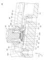
図6は、第2実施形態に係る多方向入力装置100-2の外観斜視図である。図7は、第2実施形態に係る多方向入力装置100-2の上面側を示す分解斜視図である。図8は、第2実施形態に係る多方向入力装置100-2の下面側を示す分解斜視図である。図9は、第2実施形態に係る多方向入力装置100-2の断面図である。図10は、第2実施形態に係る多方向入力装置100-2の断面斜視図である。 Second Embodiment
Fig. 6 is an external perspective view of the multi-directional input device 100-2 according to the second embodiment. Fig. 7 is an exploded perspective view showing the upper surface side of the multi-directional input device 100-2 according to the second embodiment. Fig. 8 is an exploded perspective view showing the lower surface side of the multi-directional input device 100-2 according to the second embodiment. Fig. 9 is a cross-sectional view of the multi-directional input device 100-2 according to the second embodiment. Fig. 10 is a cross-sectional perspective view of the multi-directional input device 100-2 according to the second embodiment.
以下、第2実施形態に係る多方向入力装置100-2に関し、第1実施形態からの変更点について説明する。Below, we will explain the changes made to the multi-directional input device 100-2 according to the second embodiment from the first embodiment.
図6~図8に示すように、第2実施形態に係る多方向入力装置100-2は、起歪体120の固定片123がより外側に設けられている点で、第1実施形態に係る多方向入力装置100と異なる。As shown in Figures 6 to 8, the multi-directional input device 100-2 of the second embodiment differs from the
また、図9および図10に示すように、第2実施形態に係る多方向入力装置100-2は、FPC131が起歪体120の変形部122の下面に接着されている点では第1実施形態と変わらないが、基板160および弾性部材170が、起歪体120の変形部122の下面よりも下側に設けられている点で、第1実施形態と異なる。Also, as shown in Figures 9 and 10, the multi-directional input device 100-2 according to the second embodiment is the same as the first embodiment in that the
但し、第2実施形態に係る多方向入力装置100-2は、FPC131の基部131Aの中央に円形の開口部131Dが形成されており、弾性部材170の一部(中央の凸部)が、開口部131Dを貫通して、開口部131Dよりも上方に突出している。However, in the multi-directional input device 100-2 according to the second embodiment, a
また、第2実施形態に係る多方向入力装置100-2は、FPC131の基部131Aが円形状を有しており、FPC131が突出部132を有していない。このため、第2実施形態に係る多方向入力装置100-2は、4つの歪検知素子133が、FPC131の基部131Aに搭載されている。In addition, in the multi-directional input device 100-2 according to the second embodiment, the
以上、本発明の一実施形態について詳述したが、本発明はこれらの実施形態に限定されるものではなく、特許請求の範囲に記載された本発明の要旨の範囲内において、種々の変形又は変更が可能である。Although one embodiment of the present invention has been described in detail above, the present invention is not limited to these embodiments, and various modifications and variations are possible within the scope of the gist of the present invention as described in the claims.
例えば、多方向入力装置100において、弾性部材170は、可動接点171を有さず、基板160は、161A,161Bを有さなくてもよい。また、多方向入力装置100において、弾性部材170は、クリック感を呈示しないものであってもよい。For example, in the
本国際出願は、2022年3月10日に出願した日本国特許出願第2022-037451号に基づく優先権を主張するものであり、当該出願の全内容を本国際出願に援用する。This international application claims priority to Japanese Patent Application No. 2022-037451, filed on March 10, 2022, the entire contents of which are incorporated herein by reference.
100,100-2 多方向入力装置
102 キャップ
103 プランジャー
103A 突起
110 機器本体
111 平面部
112 機器側突出部
120 起歪体
122 変形部
122A 貫通穴
123 固定片
125 筒状部
125A 上部空間
125B 下部空間
125C 溝
130 荷重検出器
131 FPC
131A 基部
131B 引き出し部
131C 接続部
131D 開口部
132 突出部
133 歪検知素子
160 基板
161A,161B 固定接点
162 腕部
162A 貫通穴
165 ネジ
170 弾性部材
171 可動接点 100, 100-2
Claims (13)
Translated fromJapanese筒状部と、前記筒状部の外側に設けられた変形部とを有する起歪体と、
前記起歪体の筒状部の内部に設けられたプランジャーと、
前記起歪体の変形部に設けられた歪検知素子と、
前記起歪体の前記筒状部の底部に設けられた基板と、
前記基板と前記プランジャーの底部との間に設けられた弾性部材と
を備え、
前記起歪体は、前記変形部の外側の端部で機器本体に固定され、
前記基板は、前記起歪体に固定され、
前記プランジャーが一体に設けられており、且つ、前記筒状部の上部および外側を覆う、キャップを備え、
前記起歪体の筒状部の内部は、
前記プランジャーが挿通される上部空間と、
前記上部空間の下側に形成され、前記上部空間よりも内径が大きく、且つ、前記弾性部材が配置される下部空間とを有する
ことを特徴とする多方向入力装置。 A multi-directional input device capable of tilting and pressing,
A strain generating body having a cylindrical portion and a deformation portion provided on the outside of the cylindrical portion;
A plunger provided inside the cylindrical portion of the strain generating body;
A strain sensing element provided on a deformation portion of the strain generating body;
A substrate provided at a bottom of the cylindrical portion of the strain generating body;
an elastic member provided between the base plate and the bottom of the plunger;
The strain body is fixed to a device body at an outer end of the deformation portion,
The substrate is fixed to the strain body,
a cap provided integrally with the plunger and covering an upper portion and an outside of the cylindrical portion;
The inside of the cylindrical portion of the strain generating body is
an upper space through which the plunger is inserted;
a lower space formed below the upper space, having an inner diameter larger than that of the upper space, and in which the elastic member is disposed;
A multi-directional input device comprising:
前記筒状部の下端から4方向に向かう上下方向の厚みより平面方向の幅が広い板状であるThe cylindrical portion has a plate shape whose width in a planar direction is wider than its thickness in the up-down direction in four directions from the lower end of the cylindrical portion.
ことを特徴とする請求項1に記載の多方向入力装置。The multi-directional input device according to claim 1 .
筒状部と、前記筒状部の外側に設けられた変形部とを有する起歪体と、
前記起歪体の筒状部の内部に設けられたプランジャーと、
前記起歪体の変形部に設けられた歪検知素子と、
前記起歪体の前記筒状部の底部に設けられた基板と、
前記基板と前記プランジャーの底部との間に設けられた弾性部材と
を備え、
前記起歪体は、前記変形部の外側の端部で機器本体に固定され、
前記基板は、前記起歪体に固定され、
前記プランジャーが一体に設けられており、且つ、前記筒状部の上部および外側を覆う、キャップを備え、
前記プランジャーの外周面には、4方向に突出した突起が設けられており、
前記起歪体の前記筒状部の内周面には、4方向に設けられ、前記突起がスライド可能な溝が上下方向に延在して設けられている
ことを特徴とする多方向入力装置。A multi-directional input device capable of tilting and pressing,
A strain generating body having a cylindrical portion and a deformation portion provided on the outside of the cylindrical portion;
A plunger provided inside the cylindrical portion of the strain generating body;
A strain sensing element provided on a deformation portion of the strain generating body;
A substrate provided at a bottom of the cylindrical portion of the strain generating body;
an elastic member provided between the substrate and the bottom of the plunger;
Equipped with
The strain body is fixed to a device body at an outer end of the deformation portion,
The substrate is fixed to the strain body,
a cap provided integrally with the plunger and covering an upper portion and an outside of the cylindrical portion;
The plunger has four projections on its outer circumferential surface.
a groove extending in avertical direction and in which the protrusions can slide is provided on an inner peripheral surface of the cylindrical portion of the strain generating body in four directions.
前記筒状部の下端から4方向に向かう上下方向の厚みより平面方向の幅が広い板状である
ことを特徴とする請求項3に記載の多方向入力装置。 The deformation portion of the strain generating body is
The multi-directional input device according to claim3 , wherein the cylindrical portion is in the form of a plate having a width in a planar direction greater than a thickness in a vertical direction extending in four directions from a lower end of the cylindrical portion.
筒状部と、前記筒状部の外側に設けられた変形部とを有する起歪体と、
前記起歪体の筒状部の内部に設けられたプランジャーと、
前記起歪体の変形部に設けられた歪検知素子と、
前記起歪体の前記筒状部の底部に設けられた基板と、
前記基板と前記プランジャーの底部との間に設けられた弾性部材と
を備え、
前記起歪体は、前記変形部の外側の端部で機器本体に固定され、
前記基板は、前記起歪体に固定され、
前記起歪体の前記変形部は、
前記筒状部の下端から4方向に向かう上下方向の厚みより平面方向の幅が広い板状であり、
前記機器本体は、
前記変形部の前記外側の端部と対向する位置に、平面部から上方に突出して設けられた機器側突出部を有し、
前記変形部の前記外側の端部は、
前記機器側突出部に固定される
ことを特徴とする多方向入力装置。A multi-directional input device capable of tilting and pressing,
A strain generating body having a cylindrical portion and a deformation portion provided on the outside of the cylindrical portion;
A plunger provided inside the cylindrical portion of the strain generating body;
A strain sensing element provided on a deformation portion of the strain generating body;
A substrate provided at a bottom of the cylindrical portion of the strain generating body;
an elastic member provided between the substrate and the bottom of the plunger;
Equipped with
The strain body is fixed to a device body at an outer end of the deformation portion,
The substrate is fixed to the strain body,
The deformation portion of the strain generating body is
The cylindrical portion has a plate shape whose width in a planar direction is wider than its thickness in a vertical direction in four directions from the lower end of the cylindrical portion,
The device body includes:
a device-side protrusion provided at a position opposite to the outer end of the deformation portion and protruding upward from the flat portion,
The outer end of the deformation portion is
Amulti-directional input device, characterized in that it is fixed to the device-side protrusion.
筒状部と、前記筒状部の外側に設けられた変形部とを有する起歪体と、
前記起歪体の筒状部の内部に設けられたプランジャーと、
前記起歪体の変形部に設けられた歪検知素子と、
前記起歪体の前記筒状部の底部に設けられた基板と、
前記基板と前記プランジャーの底部との間に設けられた弾性部材と
を備え、
前記起歪体は、前記変形部の外側の端部で機器本体に固定され、
前記基板は、前記起歪体に固定され、
前記起歪体の前記変形部は、
前記筒状部の下端から4方向に向かう上下方向の厚みより平面方向の幅が広い板状であり、
前記変形部の前記外側の端部は、
前記変形部の他の部分よりも下方に突出している
ことを特徴とする多方向入力装置。A multi-directional input device capable of tilting and pressing,
A strain generating body having a cylindrical portion and a deformation portion provided on the outside of the cylindrical portion;
A plunger provided inside the cylindrical portion of the strain generating body;
A strain sensing element provided on a deformation portion of the strain generating body;
A substrate provided at a bottom of the cylindrical portion of the strain generating body;
an elastic member provided between the substrate and the bottom of the plunger;
Equipped with
The strain body is fixed to a device body at an outer end of the deformation portion,
The substrate is fixed to the strain body,
The deformation portion of the strain generating body is
The cylindrical portion has a plate shape whose width in a planar direction is wider than its thickness in a vertical direction in four directions from the lower end of the cylindrical portion,
The outer end of the deformation portion is
Amulti-directional input device, characterized in that the deformation portion protrudes downward further than other portions of the deformation portion.
筒状部と、前記筒状部の外側に設けられた変形部とを有する起歪体と、
前記起歪体の筒状部の内部に設けられたプランジャーと、
前記起歪体の変形部に設けられた歪検知素子と、
前記起歪体の前記筒状部の底部に設けられた基板と、
前記基板と前記プランジャーの底部との間に設けられた弾性部材と
を備え、
前記起歪体は、前記変形部の外側の端部で機器本体に固定され、
前記基板は、前記起歪体に固定され、
前記起歪体の前記変形部は、
前記筒状部の下端から4方向に向かう上下方向の厚みより平面方向の幅が広い板状であり、
前記起歪体は、
前記筒状部の下端から4方向に突出して設けられた固定片を有し、
前記固定片に前記基板が固定される
ことを特徴とする多方向入力装置。A multi-directional input device capable of tilting and pressing,
A strain generating body having a cylindrical portion and a deformation portion provided on the outside of the cylindrical portion;
A plunger provided inside the cylindrical portion of the strain generating body;
A strain sensing element provided on a deformation portion of the strain generating body;
A substrate provided at a bottom of the cylindrical portion of the strain generating body;
an elastic member provided between the substrate and the bottom of the plunger;
Equipped with
The strain body is fixed to a device body at an outer end of the deformation portion,
The substrate is fixed to the strain body,
The deformation portion of the strain generating body is
The cylindrical portion has a plate shape whose width in a planar direction is wider than its thickness in a vertical direction in four directions from the lower end of the cylindrical portion,
The strain body is
The cylindrical portion has a fixing piece protruding in four directions from a lower end thereof,
Amulti-directional input device, characterized in that the substrate is fixed to the fixing piece.
前記起歪体の前記固定片よりも下方に突出した位置に設けられている
ことを特徴とする請求項7に記載の多方向入力装置。 The deformation portion of the strain generating body is
The multi-directional input device according to claim7 , wherein the strain generating body is provided at a position protruding downward from the fixed piece.
フレキシブルプリント配線基板に搭載されており、
前記フレキシブルプリント配線基板は、
前記起歪体の前記変形部の下面に接着されており、
前記基板は、
前記起歪体の前記変形部の前記下面よりも上側に設けられており、
前記基板の上面に設けられている2つの固定接点は、前記基板に設けられたスルーホー
ルを介して、前記フレキシブルプリント配線基板に電気的に接続される
ことを特徴とする請求項8に記載の多方向入力装置。 The strain sensing element is
It is mounted on a flexible printed circuit board,
The flexible printed wiring board is
The strain generating body is bonded to a lower surface of the deformation portion,
The substrate is
The deformation portion of the strain generating body is provided above the lower surface of the strain generating body,
The multi-directional input device according to claim8 , wherein the two fixed contacts provided on the upper surface of the substrate are electrically connected to the flexible printed wiring board via through holes provided in the substrate.
筒状部と、前記筒状部の外側に設けられた変形部とを有する起歪体と、
前記起歪体の筒状部の内部に設けられたプランジャーと、
前記起歪体の変形部に設けられた歪検知素子と、
前記起歪体の前記筒状部の底部に設けられた基板と、
前記基板と前記プランジャーの底部との間に設けられた弾性部材と
を備え、
前記起歪体は、前記変形部の外側の端部で機器本体に固定され、
前記基板は、前記起歪体に固定され、
前記歪検知素子は、
フレキシブルプリント配線基板に搭載されており、
前記フレキシブルプリント配線基板は、
前記起歪体の前記変形部の下面に接着されており、
前記基板は、
前記起歪体の前記変形部の前記下面よりも下側に設けられており、
前記フレキシブルプリント配線基板は、
前記弾性部材の一部が貫通する開口部が形成されている。
ことを特徴とする多方向入力装置。A multi-directional input device capable of tilting and pressing,
A strain generating body having a cylindrical portion and a deformation portion provided on the outside of the cylindrical portion;
A plunger provided inside the cylindrical portion of the strain generating body;
A strain sensing element provided on a deformation portion of the strain generating body;
A substrate provided at a bottom of the cylindrical portion of the strain generating body;
an elastic member provided between the substrate and the bottom of the plunger;
Equipped with
The strain body is fixed to a device body at an outer end of the deformation portion,
The substrate is fixed to the strain body,
The strain sensing element is
It is mounted on a flexible printed circuit board,
The flexible printed wiring board is
The strain generating body is bonded to a lower surface of the deformation portion,
The substrate is
The strain gauge is provided below the lower surface of the deformation portion of the strain gauge,
The flexible printed wiring board is
An opening is formed through which a portion of the elastic member passes.
Amulti-directional input device comprising:
ことを特徴とする請求項1~10のいずれか一項に記載の多方向入力装置。The multi-directional input device according to any one of claims 1 to 10.
前記弾性部材は、当該弾性部材の下面に、当該弾性部材の弾性変形に伴って前記基板の前記2つの固定接点に接触する可動接点を有するThe elastic member has a movable contact on a lower surface of the elastic member, the movable contact being adapted to come into contact with the two fixed contacts of the substrate as the elastic member is elastically deformed.
ことを特徴とする請求項11に記載の多方向入力装置。The multi-directional input device according to claim 11 .
ことを特徴とする請求項5~10のいずれか一項に記載の多方向入力装置。The multi-directional input device according to any one of claims 5 to 10.
Applications Claiming Priority (3)
| Application Number | Priority Date | Filing Date | Title |
|---|---|---|---|
| JP2022037451 | 2022-03-10 | ||
| JP2022037451 | 2022-03-10 | ||
| PCT/JP2023/005033WO2023171259A1 (en) | 2022-03-10 | 2023-02-14 | Multidirectional input device |
Publications (3)
| Publication Number | Publication Date |
|---|---|
| JPWO2023171259A1 JPWO2023171259A1 (en) | 2023-09-14 |
| JPWO2023171259A5 JPWO2023171259A5 (en) | 2024-05-28 |
| JP7589424B2true JP7589424B2 (en) | 2024-11-26 |
Family
ID=87936720
Family Applications (1)
| Application Number | Title | Priority Date | Filing Date |
|---|---|---|---|
| JP2024505982AActiveJP7589424B2 (en) | 2022-03-10 | 2023-02-14 | Multi-directional input device |
Country Status (4)
| Country | Link |
|---|---|
| US (1) | US20240411337A1 (en) |
| JP (1) | JP7589424B2 (en) |
| CN (1) | CN118715586A (en) |
| WO (1) | WO2023171259A1 (en) |
Citations (4)
| Publication number | Priority date | Publication date | Assignee | Title |
|---|---|---|---|---|
| JP2003084915A (en) | 2001-09-11 | 2003-03-20 | Alps Electric Co Ltd | Coordinate input device |
| JP2003092045A (en) | 2001-09-19 | 2003-03-28 | Hosiden Corp | Multi-direction input device |
| JP2008059210A (en) | 2006-08-30 | 2008-03-13 | Alps Electric Co Ltd | Input device |
| JP2013047871A (en) | 2011-08-29 | 2013-03-07 | Alps Electric Co Ltd | Input device |
Family Cites Families (2)
| Publication number | Priority date | Publication date | Assignee | Title |
|---|---|---|---|---|
| US5541622A (en)* | 1990-07-24 | 1996-07-30 | Incontrol Solutions, Inc. | Miniature isometric joystick |
| US5594618A (en)* | 1995-02-06 | 1997-01-14 | Compaq Computer Corporation | Collapsible pointing stick apparatus for a portable computer |
- 2023
- 2023-02-14WOPCT/JP2023/005033patent/WO2023171259A1/ennot_activeCeased
- 2023-02-14JPJP2024505982Apatent/JP7589424B2/enactiveActive
- 2023-02-14CNCN202380021780.5Apatent/CN118715586A/enactivePending
- 2024
- 2024-08-23USUS18/813,564patent/US20240411337A1/enactivePending
Patent Citations (4)
| Publication number | Priority date | Publication date | Assignee | Title |
|---|---|---|---|---|
| JP2003084915A (en) | 2001-09-11 | 2003-03-20 | Alps Electric Co Ltd | Coordinate input device |
| JP2003092045A (en) | 2001-09-19 | 2003-03-28 | Hosiden Corp | Multi-direction input device |
| JP2008059210A (en) | 2006-08-30 | 2008-03-13 | Alps Electric Co Ltd | Input device |
| JP2013047871A (en) | 2011-08-29 | 2013-03-07 | Alps Electric Co Ltd | Input device |
Also Published As
| Publication number | Publication date |
|---|---|
| CN118715586A (en) | 2024-09-27 |
| US20240411337A1 (en) | 2024-12-12 |
| JPWO2023171259A1 (en) | 2023-09-14 |
| WO2023171259A1 (en) | 2023-09-14 |
Similar Documents
| Publication | Publication Date | Title |
|---|---|---|
| US6373265B1 (en) | Electrostatic capacitive touch sensor | |
| US6530283B2 (en) | Force sensor | |
| US9292051B2 (en) | Touch pad input device | |
| US6894507B2 (en) | Capacitance type sensor | |
| US6867601B2 (en) | Capacitance type sensor | |
| JP3380996B2 (en) | Capacitive force sensor | |
| JP7589424B2 (en) | Multi-directional input device | |
| JP4629621B2 (en) | Switch device | |
| JP3380998B2 (en) | Capacitive force sensor | |
| JP4459428B2 (en) | Operation amount detection device | |
| US20030066739A1 (en) | Controller with tactile feedback | |
| JP3971079B2 (en) | Input device and detection device | |
| CN116209885B (en) | Load sensor device | |
| CN213814621U (en) | Device for measuring force and position | |
| JP3842016B2 (en) | Input device | |
| JP7596628B2 (en) | Multi-directional input device | |
| JP2011238516A (en) | Switching device with touch detection function | |
| JPH10333822A (en) | Coordinate inputting device | |
| WO2023157299A1 (en) | Input device and controller | |
| JP2002236552A (en) | Coordinate input device | |
| CN105304382A (en) | Key device | |
| JP4664873B2 (en) | Switch device | |
| JP2003084915A (en) | Coordinate input device | |
| US12148582B2 (en) | Input device | |
| KR102075578B1 (en) | Force sensor switch with double elastic structure |
Legal Events
| Date | Code | Title | Description |
|---|---|---|---|
| A521 | Request for written amendment filed | Free format text:JAPANESE INTERMEDIATE CODE: A523 Effective date:20240304 | |
| A621 | Written request for application examination | Free format text:JAPANESE INTERMEDIATE CODE: A621 Effective date:20240304 | |
| A131 | Notification of reasons for refusal | Free format text:JAPANESE INTERMEDIATE CODE: A131 Effective date:20240903 | |
| A521 | Request for written amendment filed | Free format text:JAPANESE INTERMEDIATE CODE: A523 Effective date:20241002 | |
| TRDD | Decision of grant or rejection written | ||
| A01 | Written decision to grant a patent or to grant a registration (utility model) | Free format text:JAPANESE INTERMEDIATE CODE: A01 Effective date:20241015 | |
| A61 | First payment of annual fees (during grant procedure) | Free format text:JAPANESE INTERMEDIATE CODE: A61 Effective date:20241023 | |
| R150 | Certificate of patent or registration of utility model | Ref document number:7589424 Country of ref document:JP Free format text:JAPANESE INTERMEDIATE CODE: R150 |