JP7589294B1 - Ultrasound diagnostic device and storage medium - Google Patents
Ultrasound diagnostic device and storage mediumDownload PDFInfo
- Publication number
- JP7589294B1 JP7589294B1JP2023101164AJP2023101164AJP7589294B1JP 7589294 B1JP7589294 B1JP 7589294B1JP 2023101164 AJP2023101164 AJP 2023101164AJP 2023101164 AJP2023101164 AJP 2023101164AJP 7589294 B1JP7589294 B1JP 7589294B1
- Authority
- JP
- Japan
- Prior art keywords
- point
- indicator
- probe
- distance
- corresponding point
- Prior art date
- Legal status (The legal status is an assumption and is not a legal conclusion. Google has not performed a legal analysis and makes no representation as to the accuracy of the status listed.)
- Active
Links
Images


Classifications
- A—HUMAN NECESSITIES
- A61—MEDICAL OR VETERINARY SCIENCE; HYGIENE
- A61B—DIAGNOSIS; SURGERY; IDENTIFICATION
- A61B8/00—Diagnosis using ultrasonic, sonic or infrasonic waves
- A61B8/44—Constructional features of the ultrasonic, sonic or infrasonic diagnostic device
- A61B8/4444—Constructional features of the ultrasonic, sonic or infrasonic diagnostic device related to the probe
- A—HUMAN NECESSITIES
- A61—MEDICAL OR VETERINARY SCIENCE; HYGIENE
- A61B—DIAGNOSIS; SURGERY; IDENTIFICATION
- A61B8/00—Diagnosis using ultrasonic, sonic or infrasonic waves
- A61B8/46—Ultrasonic, sonic or infrasonic diagnostic devices with special arrangements for interfacing with the operator or the patient
- A61B8/461—Displaying means of special interest
- A—HUMAN NECESSITIES
- A61—MEDICAL OR VETERINARY SCIENCE; HYGIENE
- A61B—DIAGNOSIS; SURGERY; IDENTIFICATION
- A61B8/00—Diagnosis using ultrasonic, sonic or infrasonic waves
- A61B8/52—Devices using data or image processing specially adapted for diagnosis using ultrasonic, sonic or infrasonic waves
- A61B8/5215—Devices using data or image processing specially adapted for diagnosis using ultrasonic, sonic or infrasonic waves involving processing of medical diagnostic data
Landscapes
- Health & Medical Sciences (AREA)
- Life Sciences & Earth Sciences (AREA)
- Engineering & Computer Science (AREA)
- Radiology & Medical Imaging (AREA)
- Heart & Thoracic Surgery (AREA)
- Biophysics (AREA)
- Nuclear Medicine, Radiotherapy & Molecular Imaging (AREA)
- Pathology (AREA)
- Veterinary Medicine (AREA)
- Biomedical Technology (AREA)
- Physics & Mathematics (AREA)
- Medical Informatics (AREA)
- Molecular Biology (AREA)
- Surgery (AREA)
- Animal Behavior & Ethology (AREA)
- General Health & Medical Sciences (AREA)
- Public Health (AREA)
- Computer Vision & Pattern Recognition (AREA)
- Ultra Sonic Daignosis Equipment (AREA)
Abstract
Translated fromJapanese
Description
Translated fromJapanese本発明は、インジケータを表示する超音波診断装置、当該超音波診断装置で実行される命令を含む記憶媒体に関する。The present invention relates to an ultrasound diagnostic device that displays an indicator, and a storage medium that contains instructions that are executed by the ultrasound diagnostic device.
超音波診断装置、CT、MRIなどの様々な医用装置は、非侵襲的に被検体を検査することができるので、定期検診や人間ドッグなどで使用されている。定期検診や人間ドッグでは、医用装置を用いて被検体の検査部位の3Dの医用画像データを取得し、医師が医用画像に基づいて被検体の画像診断が行われる。この画像診断によって、被検体に腫瘍や病変と考えられる部位を発見することがある。このような部位が発見された場合、医師は、超音波診断装置を使用して、患者に穿刺針を刺し入れて組織を採取したり、患者に穿刺針を差し入れて治療することがある。Various medical devices such as ultrasound diagnostic devices, CT scanners, and MRI scanners can examine subjects non-invasively, and are therefore used in routine checkups and health screenings. During routine checkups and health screenings, the medical devices are used to obtain 3D medical image data of the subject's examination area, and a doctor performs image diagnosis on the subject based on the medical images. This image diagnosis may discover an area in the subject that is thought to be a tumor or lesion. If such an area is discovered, the doctor may use the ultrasound diagnostic device to insert a puncture needle into the patient to extract tissue or to insert a puncture needle into the patient to provide treatment.
患者に穿刺針を刺し入れて治療又は組織の採取を行なう場合、骨や大血管などを避けながらターゲット(例えば、腫瘍)に穿刺針を刺す必要がある。そこで、穿刺針を刺し入れる前に、超音波画像を見ながら穿刺針の挿入経路に適した領域を特定し、挿入経路を特定する事前準備が行われる。事前準備で挿入経路を決定した後、穿刺作業が実行される。穿刺作業では、表示部に、事前準備で特定した領域を表示させて、穿刺が行われる。When inserting a puncture needle into a patient for treatment or tissue sampling, it is necessary to insert the needle into the target (e.g., a tumor) while avoiding bones, large blood vessels, etc. Therefore, before inserting the puncture needle, a preparation is performed in advance to identify an area suitable for the insertion path of the puncture needle while viewing an ultrasound image and to identify the insertion path. After the insertion path is determined in the preparation, the puncture operation is carried out. In the puncture operation, the area identified in the preparation is displayed on the display unit, and the puncture is performed.
穿刺作業は、事前準備とは別の日時で行われる場合がある。また、事前準備の作業者と別の人が穿刺作業をする場合もある。このような場合、穿刺作業では、事前準備で特定された領域を探索して、同じ領域を表示させる必要がある。しかし、穿刺を行うときに、事前準備で特定された領域と同じ領域を探索することは容易ではない。そこで、事前準備で特定された領域と同じ領域を探索する手法が開示されている(特許文献1参照)。The puncture operation may be performed on a different date and time from the advance preparation. Also, the puncture operation may be performed by a different person than the operator who performed the advance preparation. In such cases, the puncture operation needs to search for the area identified in the advance preparation and display the same area. However, when performing the puncture, it is not easy to search for the same area as the area identified in the advance preparation. Therefore, a method for searching for the same area as the area identified in the advance preparation has been disclosed (see Patent Document 1).
特許文献1では、事前準備で特定された領域の角部C1′,C2′,C3′,C4′の位置情報を記憶しておき、穿刺作業のときに、角部C1′,C2′,C3′,C4′の位置情報に基づいて、事前準備で特定された領域を探索する。具体的には、事前準備で特定された領域の角部C1′,C2′,C3′,C4′と、リアルタイムの超音波画像の送受信領域の角部C1,C2,C3,C4との間の距離D1、D2、D3、D4を表すインジケータId1,Id2,Id3,Id4を表示部に表示させる。インジケータId1,Id2,Id3,Id4は、距離D1、D2、D3、D4に応じた面積の四角形で表されている。距離が短くなると、インジケータの四角形の面積が小さくなり、距離が零になると、インジケータは「+」の図形に変化する。したがって、ユーザは、インジケータが表す四角形の面積の大きさを参考にして、事前準備で特定された領域を探索することが可能である。In
しかし、特許文献1の手法では、ユーザは、4つのインジケータId1,Id2,Id3,Id4の四角形の面積の大きさを同時に確認しながら、事前準備で特定された領域が表示されるように、プローブを操作する必要がある。したがって、ユーザは、4つのインジケータId1,Id2,Id3,Id4の四角形の面積がどのように変化しているかを同時に把握しながら、プローブを操作する必要があるので、プローブの位置合わせに手間が掛かるという問題がある。However, in the method of
したがって、事前に特定した領域を探索する場合に、プローブを容易に位置合わせすることができる技術が望まれている。Therefore, there is a need for technology that can easily align a probe when searching a pre-specified area.
本発明の第1の観点は、プローブであって、前記プローブの超音波の送受信領域は、第1の点と、前記第1の点とは異なる第2の点と、前記第1および第2の点とは異なる第3の点とを含む、プローブと、
表示部と、
少なくとも1つのプロセッサと
を含む超音波診断装置であって、
前記少なくとも1つのプロセッサは、
前記被検体の前記送受信領域に対応する第1の領域の位置情報をメモリに記憶させることであって、前記被検体の第1の領域は、前記第1の点に対応する第1の対応点と、前記第2の点に対応する第2の対応点と、前記第3の点に対応する第3の対応点とを含み、前記第1の対応点、前記第2の対応点、および前記第3の対応点の位置情報をメモリに記憶させること、
前記第1の対応点、前記第2の対応点、および前記第3の対応点の位置情報を記憶した後、リアルタイムの超音波の送受信領域の前記第1の点と前記第1の対応点との間の第1の距離を示す第1のインジケータを表示部に表示させること、
第1のインジケータが、前記第1の距離が零であることを示す表示態様に変化した後で、リアルタイムの前記プローブの超音波の送受信領域の前記第2の点と前記第2の対応点との間の第2の距離を示す第2のインジケータを表示部に表示させること、
前記第2のインジケータが、前記第2の距離が零であることを示す表示態様に変化した後で、リアルタイムの超音波の送受信領域の前記第3の点と前記第3の対応点との間の第3の距離を示す第3のインジケータを表示部に表示させること
を実行する、超音波診断装置である。 A first aspect of the present invention is a probe, the ultrasonic wave transmission/reception region of the probe including a first point, a second point different from the first point, and a third point different from the first and second points;
A display unit;
at least one processor,
The at least one processor
storing position information of a first region of the subject corresponding to the transmitting/receiving region in a memory, the first region of the subject including a first corresponding point corresponding to the first point, a second corresponding point corresponding to the second point, and a third corresponding point corresponding to the third point, and storing position information of the first corresponding point, the second corresponding point, and the third corresponding point in a memory;
displaying, on a display unit, a first indicator indicating a first distance between the first point and the first corresponding point in a transmission/reception region of ultrasonic waves in real time, after storing position information of the first corresponding point, the second corresponding point, and the third corresponding point;
displaying, on a display unit, a second indicator indicating a second distance between the second point and the second corresponding point in a transmission/reception region of ultrasonic waves of the probe in real time after the first indicator has changed to a display mode indicating that the first distance is zero;
The ultrasound diagnostic device executes, after the second indicator changes to a display mode indicating that the second distance is zero, displaying a third indicator on a display unit, the third indicator indicating a third distance between the third point in a real-time ultrasound transmission/reception area and the third corresponding point.
本発明の第2の観点は、プローブであって、前記プローブの超音波の送受信領域は、第1の点と、前記第1の点とは異なる第2の点と、前記第1および第2の点とは異なる第3の点とを含む、プローブと、
表示部と、
少なくとも1つのプロセッサと
を含む超音波診断装置に含まれる記憶媒体であって、
前記被検体の前記送受信領域に対応する第1の領域は、前記第1の点に対応する第1の対応点と、前記第2の点に対応する第2の対応点と、前記第3の点に対応する第3の対応点とを含み、
前記記憶媒体は、前記少なくとも1つのプロセッサに実行される命令を記憶しており、前記命令は、前記少なくとも1つのプロセッサに、
前記第1の対応点、前記第2の対応点、および前記第3の対応点の位置情報を前記記憶媒体又は他の記憶媒体に記憶させること、
前記第1の対応点、前記第2の対応点、および前記第3の対応点の位置情報を記憶した後、リアルタイムの超音波の送受信領域の前記第1の点と前記第1の対応点との間の第1の距離を示す第1のインジケータを表示部に表示させること、
第1のインジケータが、前記第1の距離が零であることを示す表示態様に変化した後で、リアルタイムの前記プローブの超音波の送受信領域の前記第2の点と前記第2の対応点との間の第2の距離を示す第2のインジケータを表示部に表示させること、
前記第2のインジケータが、前記第2の距離が零であることを示す表示態様に変化した後で、リアルタイムの超音波の送受信領域の前記第3の点と前記第3の対応点との間の第3の距離を示す第3のインジケータを表示部に表示させること
を実行させる、記憶媒体である。 A second aspect of the present invention is a probe, the ultrasonic wave transmission/reception region of the probe including a first point, a second point different from the first point, and a third point different from the first and second points;
A display unit;
At least one processor.
a first region corresponding to the transmission/reception region of the subject includes a first corresponding point corresponding to the first point, a second corresponding point corresponding to the second point, and a third corresponding point corresponding to the third point;
The storage medium stores instructions for execution by the at least one processor, the instructions causing the at least one processor to:
storing position information of the first corresponding point, the second corresponding point, and the third corresponding point in the storage medium or another storage medium;
displaying, on a display unit, a first indicator indicating a first distance between the first point and the first corresponding point in a transmission/reception region of ultrasonic waves in real time, after storing position information of the first corresponding point, the second corresponding point, and the third corresponding point;
displaying, on a display unit, a second indicator indicating a second distance between the second point and the second corresponding point in a transmission/reception region of ultrasonic waves of the probe in real time after the first indicator has changed to a display mode indicating that the first distance is zero;
The storage medium executes to cause a display unit to display a third indicator indicating a third distance between the third point in the real-time ultrasonic transmission/reception area and the third corresponding point after the second indicator changes to a display mode indicating that the second distance is zero.
本発明では、被検体の前記送受信領域に対応する第1の領域の位置情報をメモリに記憶させることであって、前記被検体の第1の領域は、前記第1の点に対応する第1の対応点と、前記第2の点に対応する第2の対応点と、前記第3の点に対応する第3の対応点とを含み、前記第1の対応点、前記第2の対応点、および前記第3の対応点の位置情報をメモリに記憶させる。そして、第1の対応点、第2の対応点、および第3の対応点の位置情報をメモリに記憶した後、ユーザが、前記被検体の第1の領域を表示部に再び表示させる作業を行う場合、先ず、表示部に、第1のインジケータが表示される。第1のインジケータは、第1の点と第1の対応点との間の第1の距離を表している。ユーザは、第1のインジケータを見ながら、第1の距離が零になるように、プローブを操作する。第1のインジケータは、例えば、第1の距離に応じて、第1のインジケータの表示態様が変化するように設定することができる。したがって、ユーザは、表示部の第1のインジケータを見ることによって、第1の点が第1の対応点に対して遠くに離れているのか、あるいは近づいているのかを、視覚的に容易に認識することができる。ユーザがプローブを操作することにより、第1のインジケータが、「第1の距離は零である」ことを表す表示態様に変化した場合、ユーザは、第1の点が第1の対応点に一致したことを、視覚的に認識することができる。つまり、ユーザは、第1の点を第1の対応点に位置合わせできたことがわかる。そして、第1のインジケータが「第1の距離は零である」ことを示す表示態様に変化した後に、プロセッサは、表示部に次のインジケータ、即ち、第2のインジケータを表示する。In the present invention, position information of a first region corresponding to the transmitting/receiving region of a subject is stored in a memory, and the first region of the subject includes a first corresponding point corresponding to the first point, a second corresponding point corresponding to the second point, and a third corresponding point corresponding to the third point, and position information of the first corresponding point, the second corresponding point, and the third corresponding point is stored in a memory. Then, after storing the position information of the first corresponding point, the second corresponding point, and the third corresponding point in the memory, when a user performs an operation to display the first region of the subject on a display unit again, a first indicator is first displayed on the display unit. The first indicator represents a first distance between the first point and the first corresponding point. While watching the first indicator, the user operates the probe so that the first distance becomes zero. The first indicator can be set so that the display mode of the first indicator changes depending on the first distance, for example. Therefore, by looking at the first indicator on the display unit, the user can easily visually recognize whether the first point is far away from or close to the first corresponding point. When the user operates the probe and the first indicator changes to a display state indicating that "the first distance is zero," the user can visually recognize that the first point coincides with the first corresponding point. In other words, the user knows that the first point has been aligned with the first corresponding point. Then, after the first indicator changes to a display state indicating that "the first distance is zero," the processor displays the next indicator, i.e., the second indicator, on the display unit.
第2のインジケータは、第2の点と第2の対応点との間の第2の距離を表している。ユーザは、第1の点が第1の対応点からズレないように注意しながら、第2のインジケータを参考にして、第2の距離が零になるように、プローブを操作する。第2のインジケータは、例えば、第2の距離に応じて、第2のインジケータの表示態様が変化するように設定することができる。したがって、ユーザは、表示部の第2のインジケータを見ることによって、第2の点が第2の対応点に対して遠くに離れているのか、あるいは近づいているのかを、視覚的に容易に認識することができる。ユーザがプローブを操作することにより、第2のインジケータが、「第2の距離は零である」ことを表す表示態様に変化した場合、ユーザは、第2の点が第2の対応点に一致したことを、視覚的に認識することができる。つまり、ユーザは、第2の点を第2の対応点に位置合わせできたことがわかる。そして、第2のインジケータが、「第2の距離は零である」ことを表す表示態様に変化した後で、プロセッサは、表示部に次のインジケータ、即ち、第3のインジケータを表示する。The second indicator represents a second distance between the second point and the second corresponding point. The user operates the probe so that the second distance becomes zero, referring to the second indicator, while being careful not to cause the first point to deviate from the first corresponding point. The second indicator can be set, for example, so that the display mode of the second indicator changes according to the second distance. Therefore, by looking at the second indicator on the display unit, the user can visually easily recognize whether the second point is far away from or close to the second corresponding point. When the user operates the probe and the second indicator changes to a display mode indicating that the "second distance is zero", the user can visually recognize that the second point coincides with the second corresponding point. In other words, the user can know that the second point has been aligned with the second corresponding point. Then, after the second indicator changes to a display mode indicating that the "second distance is zero", the processor displays the next indicator, i.e., the third indicator, on the display unit.
第3のインジケータは、第3の点と第3の対応点との間の第3の距離を表している。ユーザは、第1の点が第1の対応点からズレないように、更に、第2の点が第2の対応点からズレないように注意しながら、第3のインジケータを参考にして、第3の距離が零になるように、プローブを操作する。第3のインジケータは、例えば、第3の距離に応じて、第3のインジケータの表示態様が変化するように設定することができる。したがって、ユーザは、表示部の第3のインジケータを見ることによって、第3の点が第3の対応点に対して遠くに離れているのか、あるいは近づいているのかを、視覚的に容易に認識することができる。ユーザがプローブを操作することにより、第3のインジケータが、「第3の距離は零である」ことを示す表示態様に変化した場合、ユーザは、第3の点が第3の対応点に一致したことを、視覚的に認識することができる。つまり、ユーザは、第3の点を第3の対応点に位置合わせできたことがわかる。The third indicator represents the third distance between the third point and the third corresponding point. The user operates the probe so that the third distance becomes zero while referring to the third indicator, while being careful not to displace the first point from the first corresponding point and not to displace the second point from the second corresponding point. The third indicator can be set, for example, so that the display mode of the third indicator changes according to the third distance. Therefore, by looking at the third indicator on the display unit, the user can visually and easily recognize whether the third point is far away from or approaching the third corresponding point. When the user operates the probe and the display mode of the third indicator changes to one indicating that the "third distance is zero", the user can visually recognize that the third point coincides with the third corresponding point. In other words, the user can recognize that the third point has been aligned with the third corresponding point.
したがって、プローブの送受信領域の第1の点、第2の点、および第3の点を、メモリに記憶した第1の対応点、第2の対応点、および第3の対応点に一致させることができるので、被検体の第1の領域を表示部に再び表示することができる。Therefore, the first point, second point, and third point of the transmitting and receiving area of the probe can be matched with the first corresponding point, second corresponding point, and third corresponding point stored in the memory, so that the first area of the subject can be displayed again on the display unit.
また、本発明では、第1のインジケータ、第2のインジケータ、および第3のインジケータを表示部に一斉に表示するのでは無く、先ず、第1のインジケータを表示する。したがって、表示部には、第1のインジケータが表示されているが、第2及び第3のインジケータは表示されていないので、ユーザは第1の点の位置合わせのみに集中することができる。第1の点の位置合わせが完了した後、第2のインジケータが表示されるので、ユーザは、第1の点が第1の対応点からズレないように注意しながら、第2のインジケータを参考にして、第2の点の位置合わせに集中することができる。そして、第2の点の位置合わせが完了した後、第3のインジケータが表示され、ユーザは、第3の点の位置合わせを行う。このように、本発明では、3つのインジケータを一斉に表示するのでは無く、第1のインジケータを表示し、第1の点の位置合わせができたら、第2のインジケータを表示し、第2の点の位置合わせができたら、第3の点インジケータを表示する。したがって、ユーザは第1の点の位置合わせ、第2の点の位置合わせ、および第3の点の位置合わせに集中することができるので、第1の点、第2の点、および第3の点の位置合わせを容易に行うことができる。In addition, in the present invention, the first indicator, the second indicator, and the third indicator are not displayed on the display unit all at once, but the first indicator is displayed first. Therefore, the display unit displays the first indicator, but the second and third indicators are not displayed, so the user can concentrate only on aligning the first point. After the alignment of the first point is completed, the second indicator is displayed, so the user can concentrate on aligning the second point by referring to the second indicator, while being careful not to cause the first point to deviate from the first corresponding point. Then, after the alignment of the second point is completed, the third indicator is displayed, and the user aligns the third point. In this way, in the present invention, the three indicators are not displayed all at once, but the first indicator is displayed, and when the alignment of the first point is completed, the second indicator is displayed, and when the alignment of the second point is completed, the third point indicator is displayed. Therefore, the user can focus on aligning the first point, aligning the second point, and aligning the third point, and can easily align the first point, the second point, and the third point.
以下、発明を実施するための形態について説明するが、本発明は、以下の形態に限定されることはない。The following describes the form for implementing the invention, but the present invention is not limited to the form below.
(1)第1の実施形態
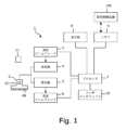
図1は、第1の実施形態における超音波診断装置1のブロック図である。
超音波診断装置1は、超音波プローブ2、送信ビームフォーマ3、送信器4、受信器5、受信ビームフォーマ6、プロセッサ7、表示部8、メモリ9、およびユーザインターフェース10を有している。(1) First Embodiment FIG. 1 is a block diagram of an ultrasonic
The ultrasound
超音波プローブ2は、アレイ状に配置された複数の振動素子2aを有している。送信ビームフォーマ3および送信器4は、超音波プローブ2内に配列された複数の振動素子2aをドライブし、振動素子2aから超音波が送信される。The
また、超音波プローブ2には磁気センサ12が設けられている。磁気センサ12は、例えばホール素子を含むことができる。磁気センサ12は、磁気発生部11から発生する磁気を検出する。磁気センサ12により検出された検出信号は、有線通信又は無線通信によりプロセッサ7に入力される。The
超音波プローブ2の振動素子2aから送信された超音波は被検体内において反射し、反射エコーが振動素子2aで受信される。振動素子2aは、受信したエコーを電気信号に変換し、この電気信号をエコー信号として受信器5に出力する。受信器5はエコー信号に対して所定の処理を実行し、受信ビームフォーマ6に出力する。受信ビームフォーマ6は、受信器5から受け取った信号に受信ビームフォーミングを実行し、エコーデータを出力する。The ultrasound waves transmitted from the
受信ビームフォーマ6は、ハードウェアビームフォーマであってもよいし、ソフトウェアビームフォーマであってもよい。受信ビームフォーマ6がソフトウェアビームフォーマである場合、受信ビームフォーマ6は、i)グラフィックス処理ユニット(GPU)、ii)マイクロプロセッサ、iii)中央処理装置(CPU)、iv)デジタル信号プロセッサ(DSP)、v)論理演算を実行することができる他の種類のプロセッサ、のうちの1つまたは複数を含む1つまたは複数のプロセッサを備えることができる。受信ビームフォーマ6を構成するプロセッサは、プロセッサ7とは別のプロセッサで構成されていてもよいし、プロセッサ7で構成されていてもよい。The receive beamformer 6 may be a hardware beamformer or a software beamformer. When the receive beamformer 6 is a software beamformer, the receive beamformer 6 may include one or more processors, including one or more of: i) a graphics processing unit (GPU); ii) a microprocessor; iii) a central processing unit (CPU); iv) a digital signal processor (DSP); v) other types of processors capable of performing logical operations. The processors constituting the receive beamformer 6 may be separate from the
超音波プローブ2は、送信ビームフォーミングおよび/または受信ビームフォーミングの全部または一部を行うための電気回路を含むことができる。例えば、送信ビームフォーマ3、送信器4、受信器5、および受信ビームフォーマ6の全部または一部は、超音波プローブ2内に設けることができる。The
プロセッサ7は、送信ビームフォーマ3、送信器4、受信器5、および受信ビームフォーマ6を制御する。また、プロセッサ7は、超音波プローブ2と電子通信している。プロセッサ7は、振動素子2aのどれがアクティブであるか、および超音波プローブ2から送信される超音波ビームの形状を制御する。プロセッサ7は表示部8とも電子通信している。プロセッサ7は、エコーデータを処理して超音波画像を生成することができる。「電子通信」という用語は、有線通信と無線通信の両方を含むように定義することができる。プロセッサ7は、一実施形態によれば中央処理装置(CPU)を含むことができる。他の実施形態によれば、プロセッサ7は、デジタル信号プロセッサ、フィールドプログラマブルゲートアレイ(FPGA)、グラフィックスプロセッシングユニット(GPU)、または他のタイプのプロセッサなど、処理機能を実行することができる他の電子構成要素や1つ以上のプロセッサを含むことができる。他の実施形態によれば、プロセッサ7は、処理機能を実行することができる複数の電子構成要素を含むことができる。例えばプロセッサ7は、中央処理装置、デジタル信号プロセッサ、フィールドプログラマブルゲートアレイ、およびグラフィックスプロセッシングユニットを含む電子構成要素のリストから選択された2つ以上の電子構成要素を含むことができる。The
また、プロセッサは、磁気センサ12からの磁気検出信号に基づいて、磁気発生部11を原点とする三次元空間の座標系における前記超音波プローブ2の位置及び傾きの情報を算出する。さらに、プロセッサ7は、プローブの位置および傾きの情報に基づいてエコー信号の三次元空間の座標系における位置情報を算出する。第1の実施形態では、磁気発生部11を原点とする三次元空間の座標系を、超音波画像の座標系というものとする。The processor also calculates information on the position and inclination of the
プロセッサ7は、RFデータを復調する複合復調器(図示せず)を含むこともできる。別の実施形態では、処理チェーン(processing chain)の早い段階で復調を実行することができる。
また、プロセッサ7は、受信ビームフォーマ6による処理によって得られたデータに基づいて、様々な超音波画像(例えば、Bモード画像、カラードップラ画像、Mモード画像、カラーMモード画像、スペクトルドップラ画像、エラストグラフィ画像、TVI画像、歪み画像、歪み速度画像、など)を生成することができる。また、1つまたは複数のモジュールが、これらの超音波画像を生成することができる。The
画像ビームおよび/または画像フレームは保存され、データがメモリに取得された時を示すタイミング情報を記録することができる。前記モジュールは、例えば、画像フレームを座標ビーム空間から表示空間座標に変換するために走査変換演算を実行する走査変換モジュールを含むことができる。被検体に処置が実施されている間にメモリから画像フレームを読み取り、その画像フレームをリアルタイムで表示する映像プロセッサモジュールを設けることもできる。映像プロセッサモジュールは画像フレームを画像メモリに保存することができ、超音波画像は画像メモリから読み取られ表示部8に表示される。The image beams and/or image frames may be stored and timing information recorded indicating when the data was acquired in memory. The modules may include, for example, a scan conversion module that performs a scan conversion operation to convert the image frames from coordinate beam space to display space coordinates. A video processor module may be provided that reads the image frames from the memory and displays the image frames in real time while a procedure is being performed on the subject. The video processor module may store the image frames in an image memory, and the ultrasound images are read from the image memory and displayed on the
本明細書において、「画像」という用語は、可視画像と可視画像を表すデータの両方を広く指すものとすることができる。また、「データ」という用語は、走査変換演算前の超音波データであるローデータ(raw data)と、走査変換演算後のデータである画像データを含み得る。
尚、プロセッサ7が担当する上述の処理タスクを、複数のプロセッサで実行するようにしてもよい。 As used herein, the term "image" may refer broadly to both a visible image and data representing a visible image, and the term "data" may include raw data, which is ultrasound data before a scan conversion operation, and image data, which is data after a scan conversion operation.
The above-mentioned processing tasks handled by the
また、受信ビームフォーマ6がソフトウェアビームフォーマである場合、ビームフォーマが実行する処理を、単一のプロセッサで実行させてもよいし、複数のプロセッサで実行させてもよい。In addition, if the receive beamformer 6 is a software beamformer, the processing performed by the beamformer may be executed by a single processor or multiple processors.
表示部8は、例えば、LED(Light Emitting Diode)表示部、LCD(Liquid Crystal Display)、有機EL(Electro-Luminescence)表示部である。また、表示部8は、モニタとタッチパネルとの組合せとしてもよい。The
メモリ9は、任意の既知のデータ記憶媒体である。一例では、超音波診断装置は、メモリとして、非一過性の記憶媒体および一過性の記憶媒体を含む。また、超音波診断装置は、複数のメモリを含むこともできる。非一過性の記憶媒体は、例えば、HDD(Hard Disk Drive:ハードディスクドライブ)、ROM(Read Only Memory)などの不揮発性の記憶媒体である。非一過性の記憶媒体は、CD(Compact Disk)やDVD(Digital Versatile Disk)などの可搬性の記憶媒体を含むことができる。プロセッサ7によって実行されるプログラムは、非一過性の記憶媒体に記憶されている。一過性の記憶媒体は、RAM(Random Access Memory)などの揮発性の記憶媒体である。The
また、メモリ9には、医用画像装置100で被検体の事前検査を行うことにより取得された3次元(3D)医用画像データ(ボリュームデータ)が記憶される。3D医用画像データは、ユーザがエコーガイド下穿刺の準備作業や、エコーガイド下穿刺の穿刺作業などを実行するときに使用される画像である。エコーガイド下穿刺において、3D医用画像データがどのように使用されるかについては後述する。The
尚、プロセッサ7は、外部記憶装置に有線接続又は無線接続することができるように構成することもできる。この場合、プロセッサ7に実行させる命令を、メモリ9と外部記憶装置との両方に分散させて記憶させることも可能である。The
ユーザインターフェース10は、ユーザ(例えば、医師、技師、操作者)の入力を受け付けることができる。例えば、ユーザインターフェース10は、ユーザからの指示や情報の入力を受け付ける。ユーザインターフェース10は、キーボード(keyboard)、ハードキー(hard key)、トラックボール(trackball)、ロータリーコントロール(rotary control)およびソフトキー等を含んでいる。ユーザインターフェース10は、ソフトキー等を表示するタッチスクリーンを含んでいてもよい。
超音波診断装置1は上記のように構成されている。 The
The ultrasonic
以下では、超音波診断装置1を用いて、被検体に穿刺を行う例を説明する。具体的には、ユーザが、被検体の穿刺ルートを決定する作業を行い、この作業の後に、ユーザが被検体に穿刺針を刺入する作業を行う例を取り挙げて、第1の実施形態の説明をする。The following describes an example of performing puncture on a subject using the ultrasound
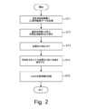
図2は、穿刺針の穿刺ルートを決定する作業のフローチャートである。
ステップST1では、医用画像装置100(図1参照)で取得された3次元(3D)の医用画像データ(ボリュームデータ)を、超音波診断装置のメモリ9に記憶する。 FIG. 2 is a flowchart showing the process of determining the puncture route of the puncture needle.
In step ST1, three-dimensional (3D) medical image data (volume data) acquired by the medical imaging device 100 (see FIG. 1) is stored in the
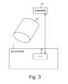
図3は、ステップST1の説明図である。
ユーザ(例えば、医師、超音波診断技師)は、超音波診断装置1を医用画像装置100に(有線又は無線)接続し、医用画像装置100で取得された3D医用画像データ(ボリュームデータ)VDを、超音波診断装置1のメモリ9に記憶する。この3D医用画像データVDは、ユーザがエコーガイド下穿刺の準備作業や、エコーガイド下穿刺の穿刺作業などを実行するときに使用される画像である。医用画像装置100は、例えば、MRI装置、CT装置、PET装置、超音波診断装置などである。尚、3D医用画像データVDを、メモリ9ではなく、超音波診断装置1がアクセス可能な外部記憶装置に記憶してもよい。
3D医用画像データVDを、超音波診断装置1のメモリ9に記憶した後、ステップST2に進む。 FIG. 3 is an explanatory diagram of step ST1.
A user (e.g., a doctor or an ultrasound diagnostic technician) connects the ultrasound
After the 3D medical image data VD is stored in the
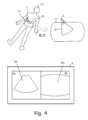
ステップST2では、表示部8に超音波画像および参照医用画像を表示する。
図4は、ステップST2の説明図である。
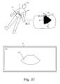
ステップST2では、ユーザは超音波プローブ2を被検体の体表面に当接させて超音波の送受信を開始する。図4の上半分には、被検体110と、被検体110の断面111の拡大図が示されている。超音波の送受信により被検体110のスキャンが行われる領域(以下、「送受信領域」と呼ぶ)を符号60で示してある。プロセッサ7は、被検体110から得られたエコー信号に基づいて作成された超音波画像UGを前記表示部8に表示させる。超音波画像UGは画像表示領域8aに表示される。超音波画像UGは例えばBモード画像である。また、プロセッサ7は、表示部8に、参照医用画像MGを表示させる。参照医用画像MGは、メモリ9に記憶された3D医用画像データVD(図3参照)に基づいて作成された断面画像である。参照医用画像MGは画像表示領域8bに表示される。超音波画像UG及び参照医用画像MGは表示部8に並べて表示されている。超音波画像UG及び参照医用画像MGを表示部8に表示させた後、ステップST3に進む。 In step ST2, the ultrasonic image and the reference medical image are displayed on the
FIG. 4 is an explanatory diagram of step ST2.
In step ST2, the user brings the
ステップST3では、ユーザは、超音波画像UGの座標系と参照医用画像MGの座標系とを対応付ける処理を行なう。具体的には、ユーザは、表示部8に表示された超音波画像UGと参照医用画像MGとを見比べながら、いずれか一方又は両方の画像の断面位置を調整して、同一断面の超音波画像UGと参照医用画像MGとを表示させる。超音波画像UGの断面の移動は、ユーザが前記超音波プローブ2を操作することによって実行される。また、参照医用画像MGの断面の移動は、ユーザがユーザインターフェース10を操作して、参照医用画像の断面を変更する指示を入力することにより実行される。In step ST3, the user performs a process of associating the coordinate system of the ultrasound image UG with the coordinate system of the reference medical image MG. Specifically, while comparing the ultrasound image UG and the reference medical image MG displayed on the
超音波画像UGの断面と、参照医用画像MGの断面が同一であるかどうかは、例えばユーザが特徴的な部位を基準にして判断する。ユーザは、表示部8に同一断面の超音波画像UGおよび参照医用画像MGが表示されていると判断したら、ユーザインターフェース10を操作して、超音波画像UGの任意の箇所に点を指定する。また、操作者は、参照医用画像MGから、超音波画像UGに指定した点と同一位置と思われる箇所を特定し、参照医用画像MGの特定した箇所にも点を指定する。ユーザは、超音波画像および参照医用画像の複数の箇所について、このような点の指定を行なう。Whether the cross section of the ultrasound image UG and the cross section of the reference medical image MG are the same is determined, for example, by the user based on characteristic sites. When the user determines that the ultrasound image UG and the reference medical image MG of the same cross section are displayed on the
上記のように、点を指定すると、これら超音波画像UGの座標系と参照医用画像MGの座標系とを対応付けることができる。したがって、前記超音波画像UGの座標系と前記参照医用画像MGの座標系との座標変換が可能になる。図5に、座標系の対応付けが終了した後の表示部8を示す。プロセッサ7は、画像表示領域8aにリアルタイムの超音波画像UGが表示されるように、表示部8を制御する。また、プロセッサ7は、3D医用画像データVDの中から、リアルタイムの超音波画像UGに対応する断面の画像を特定し、その特定した断面の画像を、参照医用画像MGとして画像表示領域8bに表示されるように、表示部8を制御する。プロセッサ7は、リアルタイムの超音波画像の座標系の位置情報を、参照医用画像MGの座標系の位置情報に座標変換することによって、3D医用画像データVDの中から、リアルタイムの超音波画像UGに対応する断面を特定することができる。また、プロセッサ7は、参照医用画像MGに重なるように輪郭線OLも表示する。輪郭線OLで囲まれる領域は、超音波画像UGに対応する領域である。座標系の対応付けが終了したら、ステップST4に進む。As described above, when a point is specified, the coordinate system of the ultrasound image UG can be associated with the coordinate system of the reference medical image MG. Therefore, it is possible to convert the coordinate system of the ultrasound image UG to the coordinate system of the reference medical image MG. FIG. 5 shows the
ステップST4では、ユーザは、超音波プローブ2で被検体110の体内を走査しながら、ターゲット(例えば、腫瘍)にアクセスするための穿刺ルート(例えば、穿刺針を刺入する位置及び刺入角度)を探索する。In step ST4, the user searches for a puncture route (e.g., the position and angle at which the puncture needle will be inserted) to access a target (e.g., a tumor) while scanning the inside of the subject 110 with the
図6はステップST4の説明図である。
ステップST4では、ユーザは、被検体110における同一断面についてのリアルタイムの超音波画像UG及び参照医用画像MGを見て、超音波プローブ2の位置を調整するとともに、プローブ2の体表面に対する角度を変えながら、穿刺ルートを探索する。図6では、ユーザは、超音波の送受信領域60に対応する被検体110の領域61(グレーでハイライトされた部分)に、最適な穿刺ルートを発見することができた例が示されている。ユーザは、最適な穿刺ルートが得られる領域61を探索することができたら、ステップST5に進む。 FIG. 6 is an explanatory diagram of step ST4.
In step ST4, the user searches for a puncture route while viewing a real-time ultrasound image UG and a reference medical image MG of the same cross section of the subject 110, and adjusting the position of the
ステップST5では、ユーザは、ユーザインターフェース10を操作して、最適な穿刺ルートが得られる領域61の位置情報を記憶させるための命令を入力する。In step ST5, the user operates the
図7は、最適な穿刺ルートが得られる領域61の位置情報を記憶させるときの説明図である。
図7では、説明の便宜上、送受信領域60と、最適な穿刺ルートが得られる領域61とを別々に示してある。
第1の実施形態では、送受信領域60の輪郭上に位置する3点C1、C2、およびC3が、最適な穿刺ルートが得られる領域61の位置情報を記憶するための基準点となる。点C1は、プローブ2のプローブ面2bの中央部2cに対応する点である。点C2は、プローブ面2bの長手方向の端部2dに対応する点である。点C3は、送受信領域60の最深部の点である。 FIG. 7 is an explanatory diagram when storing the position information of the
For ease of explanation, FIG. 7 shows a transmission/
In the first embodiment, three points C1, C2, and C3 located on the contour of the transmission/
最適な穿刺ルートが得られる領域61は、点C1に対応する対応点B1と、点C2に対応する対応点B2と、点C3に対応する対応点B3とを有している。
プロセッサ7は、最適な穿刺ルートが得られる領域61の対応点B1、B2、およびB3の位置情報を記憶する(図8参照)。 A
The
図8は、対応点の位置情報を記憶するときの説明図である。
プロセッサは、対応点B1、B2、およびB3の位置情報を、3D医用画像データVDの座標系の位置情報としてメモリに記憶する。具体的には、ユーザがユーザインターフェース10を操作して、対応点B1、B2、およびB3の位置情報を記憶させる命令を入力すると、プロセッサ7は、対応点B1、B2、およびB3の位置情報を、3D医用画像VDの座標系における点b1、b2、およびb3の位置情報としてメモリ9に記憶する。 FIG. 8 is an explanatory diagram for storing the position information of the corresponding points.
The processor stores the position information of the corresponding points B1, B2, and B3 in the memory as position information in the coordinate system of the 3D medical image data VD. Specifically, when the user operates the
これらの対応点B1、B2、およびB3の位置情報は、後述する穿刺準備時に、最適な穿刺ルートが得られる領域61をユーザが再び見つけ出すことができるようにするために使用される。最適な穿刺ルートが得られる領域61をユーザが再び見つけ出す手順については、後述する。対応点B1、B2、およびB3の位置情報が記憶されると、穿刺針の穿刺ルートを決定する作業が終了する。
穿刺針の穿刺ルートを決定する作業が終了したら、ユーザは穿刺作業を行う。 The position information of these corresponding points B1, B2, and B3 is used to enable the user to find again the
After the operation of determining the puncture route of the puncture needle is completed, the user performs the puncture operation.
図9は、穿刺作業のフロー図である。
ステップST20では、ユーザは、被検体110をプローブ2で操作して、最適な穿刺ルートが得られる領域61(図8参照)を再び見つけ出すための作業を行う。
尚、ステップST20は、ステップST11~ST16を含んでいるので、以下、ステップST11~ST16について、順に説明する。 FIG. 9 is a flow diagram of the puncture operation.
In step ST20, the user manipulates the subject 110 with the
Incidentally, since step ST20 includes steps ST11 to ST16, steps ST11 to ST16 will be described in order below.
ステップST11では、ユーザは、最適な穿刺ルートが得られる領域61を見つけ出す作業を開始する。
図10は、探索の開始直後の説明図である。
図10の左上には、被検体110をz方向から見た図、図10の右上には、被検体をx方向から見た図が示されており、図10の下半分には、表示部8が示されている。 In step ST11, the user starts the task of finding an
FIG. 10 is an explanatory diagram of the state immediately after the start of a search.
10 shows a view of the subject 110 seen from the z direction, and the top right shows a view of the subject seen from the x direction. The lower half of FIG. 10 shows the
尚、図10では、リアルタイムの送受信領域60の点C1、C2、およびC3と、最適な穿刺ルートが得られる領域61の対応点B1、B2、およびB3との位置関係を理解しやすくするため、被検体110内に、図8に示した領域61(および対応点B1、B2、およびB3)が破線で示されている。In addition, in FIG. 10, in order to make it easier to understand the positional relationship between points C1, C2, and C3 in the real-time transmission/
表示部8の画像表示領域8aは超音波画像を表示する領域であり、画像表示領域8bは超音波画像に対応する参照医用画像を表示する領域である。図10では、プローブ2は被検体110から離れており、プローブ2が空中放置された状態が示されている。したがって、画像表示領域8aおよび8bに、被検体の画像は表示されていない。The
ユーザは、ユーザインターフェース10を操作して、送受信領域60の点C1に関するインジケータId1を表示部8に表示するための命令を入力する。この命令が入力されると、プロセッサは、表示部8の画像表示領域8bにインジケータId1を表示する。インジケータId1は、リアルタイムの超音波の送受信領域60の点C1と対応点B1との間の距離D1を示している。第1の実施形態では、インジケータId1は、距離D1に応じた□(四角形)の面積で表される。距離D1が長いほどインジケータId1の面積は大きくなり、距離D1が短いほどインジケータId1の面積は小さくなる。また、距離D1が零の場合は、インジケータId1は「+」の図形で表される。したがって、ユーザは、表示部8に表示されているインジケータId1を見ることによって、点C1と対応点B1との位置関係を視覚的に容易に認識することができる。図10では、プローブ2は被検体110の体表面から離れているので、表示部8には、被検体の超音波画像および参照医用画像は表示されておらず、インジケータId1は大きい面積の四角形で表されている。The user operates the
したがって、ユーザは、表示部8のインジケータId1を見ることによって、送受信領域60の点C1が対応点B1から離れていることを視覚的に容易に認識することができる。インジケータId1が表示された後、ステップST12に進む。Therefore, by looking at the indicator Id1 on the
ステップST12では、ユーザは、最適な穿刺ルートが得られる領域61(図6参照)を見つけるために、プローブ2を被検体110の体表に接触させる。In step ST12, the user contacts the
図11は、プローブ2を被検体110の体表に接触させたときの説明図である。
ユーザがプローブ2を被検体110の体表に接触させると、表示部8の画像表示領域8aに、送受信領域60におけるスキャンにより得られた超音波画像70が表示される。また、表示部8の画像表示領域8bには、3D医用画像データVDのうち、超音波画像70に対応する断面の画像が、参照医用画像71として表示される。更に、参照医用画像71には、超音波画像70の輪郭に対応する輪郭線OLも表示される。輪郭線OLで囲まれる領域は、超音波画像70に対応する領域である。 FIG. 11 is an explanatory diagram when the
When the user brings the
また、画像表示領域8bには、インジケータId1が表示されている。ユーザがプローブ2を被検体110の体表に接触させると距離D1が短くなるので、プロセッサ7は、距離D1が短くなった分、インジケータId1の面積が小さくなるように、インジケータId1の表示態様を制御する。したがって、ユーザは画像表示領域8bのインジケータId1を見ることによって、送受信領域60の点C1が対応点B1に近づいていることを認識することができる。Indicator Id1 is also displayed in
ユーザは、画像表示領域8aおよび8bの画像を確認しながら、送受信領域60の点C1が対応点B1に一致するように、プローブ2を操作する(図12参照)。While checking the images in the
図12は、ユーザがプローブ2を操作した後の様子を示す図である。
ユーザがプローブ2を操作することによって、送受信領域60の点C1が、最適な穿刺ルートが得られる領域61の対応点B1に一致すると、距離D1がD1=0となる。D1=0になると、プロセッサ7は、インジケータId1を、「距離D1が零である」ことを示す表示態様に変化させる。具体的には、プロセッサは、インジケータId1を、「□(四角形)」から「+」の表示態様に変化させる。ユーザは、画像表示領域8bに表示されたインジケータId1が「□」から「+」の表示態様に変化することを確認することによって、点C1が対応点B1に一致したことを認識することができる。尚、第1の実施形態では、プロセッサ7は、距離D1の値が、所定の閾値TH以下(又は閾値TH未満)の値になった場合に、距離D1が零(D1=0)であると判定し、インジケータId1の表示態様を「□」から「+」に変化させる。したがって、「距離D1が零である」とは、必ずしも厳密にD1=0である必要はなく、点C1が対応点B1に十分に近い位置に存在しており、その結果、距離D1が実質的に零であると見なせる場合も含むものとして解釈されるべきである。
ユーザは、インジケータId1が「+」に変化したことを確認できたら、ステップST13に進む。 FIG. 12 is a diagram showing a state after the user operates the
When the user operates the
When the user confirms that the indicator Id1 has changed to "+", the process proceeds to step ST13.
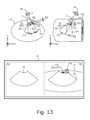
ステップST13では、次のインジケータを表示する。
図13は、ステップST13の説明図である。
ステップST13では、ユーザは、ユーザインターフェース10を操作して、次のインジケータId2を表示する命令を入力する。ユーザインターフェース10が次のインジケータId2を表示するためのユーザの入力を受け付けると、プロセッサ7は、次のインジケータId2を表示部8に表示させる。 In step ST13, the following indicators are displayed.
FIG. 13 is an explanatory diagram of step ST13.
In step ST13, the user inputs a command to display the next indicator Id2 by operating the
インジケータId2は、リアルタイムの超音波の送受信領域60の点C2と、点C2の対応点B2との間の距離D2を表している。第1の実施形態では、インジケータId2は、距離D2に応じた四角形の面積で表される。距離D2が長いほどインジケータId2の面積は大きくなり、距離D2が短いほどインジケータId2の面積は小さくなる。また、距離D2が零の場合は、インジケータId2は「+」の図形で表される。したがって、ユーザは、表示部8に表示されているインジケータId2を見ることによって、点C2と対応点B2との位置関係を視覚的に容易に認識することができる。図13では、点C2は対応点B2から離れているので、表示部8には、インジケータId2は四角形で表されている。The indicator Id2 represents the distance D2 between the point C2 in the real-time ultrasonic transmission/
したがって、ユーザは、点C2が対応点B2から離れていることを視覚的に認識することができる。インジケータId2が表示された後、ステップST14に進む。Therefore, the user can visually recognize that point C2 is far away from corresponding point B2. After indicator Id2 is displayed, proceed to step ST14.
ステップST14では、ユーザは、画像表示領域8bのインジケータId2を確認しながら、送受信領域60の点C2が対応点B2に一致するように、プローブ2を操作する。具体的には、ユーザは、点C1が対応点B1からズレないようにプローブ2を被検体110の体表面に押し当てた状態で、中心軸2eを中心にプローブ2を右回り(又は左回り)に回転する。In step ST14, while checking the indicator Id2 in the
点C1が対応点B1からズレないようにプローブ2を被検体110の体表面に押し当てた状態で、ユーザが中心軸2eを中心にプローブ2を回転すると、送受信領域60の点C2が対応点B2に近づいていく。点C2が対応点B2に近づいていくと、それに伴って距離D2が短くなるので、インジケータId2の四角形の面積が小さくなっていく。したがって、ユーザは、プローブ2を回転することによって、点C2が対応点B2に近づいていることを視覚的に認識することができる。ユーザはインジケータId2の四角形の大きさを確認しながら、点C2が対応点B2に重なるように、プローブ2の回転角度を調整する(図14参照)。When the user rotates the
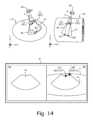
図14は、点C2が対応点B2に一致した様子を示す図である。
ユーザがプローブ2の回転角度θを調整することによって、送受信領域60の点C2が、最適な穿刺ルートが得られる領域61の対応点B2に一致すると、距離D2がD2=0となる。D2=0になると、プロセッサ7は、インジケータId2を、「距離D2が零である」ことを示す表示態様に変化させる。具体的には、プロセッサは、インジケータId2を「□(四角形)」から「+」の表示態様に変化させる。ユーザは、画像表示領域8bに表示されたインジケータId2が「□」から「+」に変化することを確認することによって、点C2が対応点B2に一致したことを認識することができる。尚、第1の実施形態では、プロセッサ7は、距離D2の値が、所定の閾値TH以下(又は閾値TH未満)の値になった場合に、距離D2が零(D2=0)であると判定し、インジケータId2の表示態様を「□」から「+」に変化させる。したがって、「距離D2が零である」とは、必ずしも厳密にD2=0である必要はなく、点C2が対応点B2に十分に近い位置に存在しており、その結果、距離D2が実質的に零であると見なせる場合も含むものとして解釈されるべきである。
ユーザは、インジケータId2が「+」に変化したことを確認できたら、ステップST15に進む。 FIG. 14 is a diagram showing a state where point C2 coincides with corresponding point B2.
When the user adjusts the rotation angle θ of the
When the user confirms that the indicator Id2 has changed to "+", the process proceeds to step ST15.
ステップST15では、次のインジケータを表示する。
図15は、ステップST15の説明図である。
ステップST15では、ユーザは、ユーザインターフェース10を操作して、次のインジケータId3を表示する命令を入力する。ユーザインターフェース10が次のインジケータId3を表示するためのユーザの入力を受け付けると、プロセッサ7は、次のインジケータId3を表示部8に表示させる。 In step ST15, the following indicators are displayed.
FIG. 15 is an explanatory diagram of step ST15.
In step ST15, the user inputs a command to display the next indicator Id3 by operating the
インジケータId3は、リアルタイムの超音波の送受信領域60の点C3と、点C3の対応点B3との間の距離D3を表している。第1の実施形態では、インジケータId3は、距離D3に応じた四角形の面積で表される。距離D3が長いほどインジケータId3の面積は大きくなり、距離D3が短いほどインジケータId3の面積は小さくなる。また、距離D3が零の場合は、インジケータId3は「+」の図形で表される。したがって、ユーザは、表示部8に表示されているインジケータId3を見ることによって、点C3と対応点B3との位置関係を視覚的に容易に認識することができる。図15では、点C3は対応点B3から離れているので、表示部8には、インジケータId3は四角形で表されている。The indicator Id3 represents the distance D3 between point C3 in the real-time ultrasonic transmission/
したがって、ユーザは、点C3が対応点B3から離れていることを視覚的に認識することができる。インジケータId3が表示された後、ステップST16に進む。Therefore, the user can visually recognize that point C3 is far away from corresponding point B3. After indicator Id3 is displayed, proceed to step ST16.
ステップST16では、ユーザは、画像表示領域8bの画像を確認しながら、送受信領域60の点C3が対応点B3に一致するように、プローブ2を操作する(図16参照)。In step ST16, while checking the image in the
図16は、プローブ2の操作方法の説明図である。
ユーザは、点C1およびC2が対応点B1およびB2からそれぞれズレないようにプローブ2を被検体110の体表面に押し当てた状態で、中心軸2eを含み送受信領域60に対して垂直な面62内でプローブ2を傾ける。 FIG. 16 is an explanatory diagram of a method for operating the
The user presses the
プローブ2を垂直面62内で矢印方向Aに傾けると、垂直面62内におけるプローブ2の傾き角δを調整することができるので、送受信領域60の点C3を対応点B3に近づけることができる。点C3が対応点B3に近づいていくと、それに伴って距離D3が短くなるので、インジケータId3(図15参照)の四角形の面積が小さくなっていく。そこで、ユーザは、インジケータId3の四角形の大きさを確認しながら、点C3が対応点B3に重なるように、プローブ2の傾き角δを調整する(図17参照)。By tilting the
図17は、点C3が対応点B3に一致した様子を示す図である。
ユーザが、プローブ2の傾き角δを調整することによって、送受信領域60の点C3が、最適な穿刺ルートが得られる領域61の対応点B3に一致すると、距離D3がD3=0となる。D3=0になると、プロセッサ7は、インジケータId3を、「距離D3が零である」ことを示す表示態様に変化させる。具体的には、プロセッサは、インジケータId3を「□(四角形)」から「+」の図形に変化させる。ユーザは、画像表示領域8bに表示されたインジケータId3が「□」から「+」に変化することを確認することによって、点C3が対応点B3に一致したことを認識することができる。尚、第1の実施形態では、プロセッサ7は、距離D3の値が、所定の閾値TH以下(又は閾値TH未満)の値になった場合に、距離D3が零(D3=0)であると判定し、インジケータId3の表示態様を「□」から「+」に変化させる。したがって、「距離D3が零である」とは、必ずしも厳密にD3=0である必要はなく、点C3が対応点B3に十分に近い位置に存在しており、その結果、距離D3が実質的に零であると見なせる場合も含むものとして解釈されるべきである。 FIG. 17 is a diagram showing a state where point C3 coincides with corresponding point B3.
When the user adjusts the tilt angle δ of the
このようにして、3つの点C1、C2、およびC3を対応点B1、B2、およびB3に位置合わせすることができる。したがって、ユーザは、最適な穿刺ルートが得られる被検体110の領域61を表示部8に再び表示することができる。最適な穿刺ルートが得られる領域61が表示部8に表示された後、ステップST21に進み、ユーザは、表示部8に表示された超音波画像70および参照医用画像71を確認しながら、被検体110に実際に穿刺を行い、フローを終了する。In this way, the three points C1, C2, and C3 can be aligned with the corresponding points B1, B2, and B3. Therefore, the user can display again on the
第1の実施形態では、ユーザは、先ず、図2に示すフローに従って、穿刺ルートを決める作業を実行する。穿刺ルートを決める場合、ユーザは、被検体110の体内から、最適な穿刺ルートが得られる領域61を特定する。最適な穿刺ルートが得られる領域61は、送受信領域60の点C1、点C2、および点C3に対応する対応点B1、対応点B2、および対応点B3を含んでいる。これらの対応点B1、対応点B2、および対応点B3の位置情報はメモリ9に記憶される。そして、対応点B1、対応点B2、および対応点B3の位置情報をメモリ9に記憶した後、ユーザは、穿刺の作業を実行する。穿刺の作業を実行する場合、ユーザは、ステップST20において、最適な穿刺ルートが得られる領域61を再び見つけ出すための作業を行う。ステップST20では、ユーザは、先ず、表示部8に、インジケータId1を表示する。インジケータId1は、点C1と対応点B1との間の距離D1を表している。ユーザは、インジケータId1を見ながら、距離D1が零になるように、プローブ2を操作する。インジケータId1は距離D1(すなわち、点C1と対応点B1との間の距離)を表している。インジケータId1は、距離D1に応じて表示態様が変化する。第1の実施形態では、□(四角形)の面積で距離D1を表し、点C1が対応点B1に一致すると、「+」に変化する。したがって、ユーザは、表示部8のインジケータId1を見ることによって、点C1が対応点B1に対して遠くに離れているのか、あるいは近づいているのかを、視覚的に容易に認識することができる。ユーザがプローブ2を操作することにより、インジケータId1が、「+」(つまり、D1=0)の表示態様に変化した場合、ユーザは、点C1が対応点B1に一致したことを、視覚的に認識することができる。つまり、ユーザは、点C1を対応点B1に位置合わせできたことがわかる。そして、インジケータId1が、「距離D1は零である」ことを表す表示態様に変化した後で、ユーザは、表示部8に次のインジケータ、即ち、インジケータId2を表示させる。In the first embodiment, the user first performs the task of determining the puncture route according to the flow shown in FIG. 2. When determining the puncture route, the user identifies an
インジケータId2は、点C2と対応点B2との間の距離D2(図13参照)を表している。ユーザは、点C1が対応点B1からズレないように注意しながら、インジケータId2を参考にして、距離D2が零になるように、プローブ2を操作する。第1の実施形態では、インジケータId2は、距離D2に応じて表示態様が変化し、□(四角形)の面積で距離D2を表し、点C2が対応点B2に一致すると、「+」に変化する。したがって、ユーザは、表示部8のインジケータId2を見ることによって、点C2が対応点B2に対して遠くに離れているのか、あるいは近づいているのかを、視覚的に容易に認識することができる。ユーザがプローブ2を操作することにより、インジケータId2が、「+」(つまり、D2=0)の表示態様に変化した場合(図14参照)、ユーザは、点C2が対応点B2に一致したことを、視覚的に認識することができる。つまり、ユーザは、点C2を対応点B2に位置合わせできたことがわかる。そして、インジケータId2が、「+」(つまり、D2=0)の表示態様に変化した後で、ユーザは、表示部8に次のインジケータ、即ち、インジケータId3を表示させる。The indicator Id2 represents the distance D2 (see FIG. 13) between the point C2 and the corresponding point B2. The user operates the
インジケータId3は、点C3と対応点B3との間の距離D3(図15参照)を表している。ユーザは、点C1が対応点B1からズレないように、更に、点C2が対応点B2からズレないように注意しながら、インジケータId3を参考にして、距離D3が零になるように、プローブ2を操作する。第1の実施形態では、インジケータId3は、距離D3に応じて表示態様が変化し、□(四角形)の面積で距離D3を表し、点C3が対応点B3に一致すると、「+」に変化する。したがって、ユーザは、表示部8のインジケータId3を見ることによって、点C3が対応点B3に対して遠くに離れているのか、あるいは近づいているのかを、視覚的に容易に認識することができる。ユーザがプローブ2を操作することにより、インジケータId3が、「+」の表示態様に変化した場合、ユーザは、点C3が対応点B3に一致したことを、視覚的に認識することができる。つまり、ユーザは、点C3を対応点B3に位置合わせできたことがわかる。The indicator Id3 represents the distance D3 (see FIG. 15) between the point C3 and the corresponding point B3. The user operates the
したがって、プローブ2の送受信領域60の点C1、点C2、および点C3を、メモリ9に記憶した対応点B1、対応点B2、および対応点B3に一致させることができるので、ユーザは、最適な穿刺ルートが得られる領域61を再び見つけ出すことができる。Therefore, points C1, C2, and C3 of the transmission/
また、第1の実施形態では、表示部8にインジケータId1、インジケータId2、およびインジケータId3を表示部8に一斉に表示するのでは無く、先ず、インジケータId1を表示する。したがって、ユーザが点C1の位置合わせを行っている間、表示部8には、図11に示すように、インジケータId1が表示されているが、インジケータId2およびId3は表示されていないので、ユーザは点C1の位置合わせのみに集中することができる。そして、点C1の位置合わせが完了した後、インジケータId2が表示されるので(図13参照)、ユーザは、点C1が対応点B1からズレないように注意しながら、インジケータId2を参考にして、点C2の位置合わせに集中することができる。点C2の位置合わせが完了した後(図14参照)、インジケータId3が表示され(図15参照)、ユーザは、点C3の位置合わせを行う。このように、第1の実施形態では、3つのインジケータId1、Id2、およびId3を一斉に表示するのでは無く、インジケータId1を表示し、点C1の位置合わせができたら、インジケータId2を表示し、点C2の位置合わせができたら、インジケータId3を表示していく。したがって、ユーザは点C1の位置合わせ、点C2の位置合わせ、および点C3の位置合わせに集中することができるので、プローブの位置合わせを容易に行うことができる。In the first embodiment, the indicator Id1 is displayed first, instead of simultaneously displaying the indicators Id1, Id2, and Id3 on the
第1の実施形態では、3つのインジケータId1、Id2、およびId3のうちのインジケータId1を最初に表示部8に表示して、点C1の位置決めを最初に行っている。点C1は、図7に示すように、プローブ2のプローブ面2bの中央部2cに対応する点である。したがって、点C1の位置決めを最初に行うと、被検体の体表面に対してプローブ面2bの中央部2cの位置を確定することができるので、残りの点C2およびC3を、プローブ2の簡単な操作で位置合わせすることができる。例えば、第1の実施形態では、点C1を最初に位置決めすることによって、点C2は、プローブ2を回転操作するだけで位置合わせすることができ(図14参照)、点C3は、プローブ2を傾ける操作をするだけで位置合わせすることができる(図17参照)。したがって、プローブ2の簡単な操作で、最適な穿刺ルートが得られる領域61を容易に見つけ出すことができる。尚、第1の実施形態では、点C1を、プローブ2のプローブ面2bの中央部2cに対応する点として設定されている。しかし、点C1は、必ずしも、プローブ面2bの中央部2cに対応する点として設定する必要は無く、プローブ面2b内の他の部分に対応する点として設定することができる。例えば、点C1をプローブ面2bの端部2f(図7参照)に対応するように設定することができる。点C1を端部2fに対応する点として設定した場合、点C1を位置決めすることによって、被検体の体表面に対してプローブ面2bの端部2fの位置を確定することができるので、残りの点C2およびC3を、プローブ2の簡単な操作で位置合わせすることができる。In the first embodiment, the indicator Id1 of the three indicators Id1, Id2, and Id3 is displayed on the
第1の実施形態では、インジケータId1、Id2、およびId3は、インジケータId1、Id2、およびId3の順で、表示部8に表示されている。しかし、インジケータId1、Id2、およびId3を表示する順序は、インジケータId1、Id2、およびId3の順に限定されることはなく、他の順でインジケータId1、Id2、およびId3を表示してもよい。例えば、インジケータId1、Id3、およびId2の順にインジケータを表示するようにしてもよい。この場合、点C1を位置決めした後、ユーザは、プローブ2を傾ける操作をすることによって、点C3を対応点B3に位置合わせする。したがって、点C2を位置合わせする前に、点C3の位置合わせが実行される。点C3を位置合わせした後、ユーザは、点C1および点C3が位置ずれしないようにプローブ2を回転操作することによって、点C2を対応点B2に位置合わせする。したがって、点C1、点C3、および点C2の順で位置決めをする場合も、プローブ2の簡単な操作で、最適な穿刺ルートが得られる領域61を容易に見つけ出すことができる。In the first embodiment, the indicators Id1, Id2, and Id3 are displayed on the
また、第1の実施形態では、点C1、点C2、および点C3のうち、点C1を最初に位置決めしている。しかし、点C1ではなく、点C2又は点C3を最初に位置決めしてもよい。In the first embodiment, point C1 is positioned first among points C1, C2, and C3. However, point C2 or C3 may be positioned first instead of point C1.
また、第1の実施形態では、送受信領域60の点C1は、プローブ面の中央部に対応し、点C2はプローブ面の端部に対応し、点C3は送受信領域60の深部に対応している。しかし、点C1、C2、およびC3を、別の位置に設置してもよい。図18は、点C1、C2、およびC3を別の位置に設定した例を示す図である。図18の(a)は、点C1、C2、およびC3が送受信領域60の角部に位置している例を示しており、図18の(b)は、点C1が送受信領域60の内部に配置されている例を示している。このように、点C1、C2、C3の位置は、送受信領域60の輪郭上の位置だけでなく、送受信領域60の内部に設定することもできる。In the first embodiment, point C1 of the transmission/
また、第1の実施形態では、3つのインジケータを使用して、最適な穿刺ルートが得られる領域61を見つけ出しているが、4つ以上のインジケータを使用してもよい。In addition, in the first embodiment, three indicators are used to find the
また、第1の実施形態では、表示部8に、扇形の超音波画像が表示される例について説明されているが、本発明は、扇形の超音波画像に限定されることはなく、任意の形状の超音波画像(例えば、正方形の超音波画像)に適用することができる。In addition, in the first embodiment, an example in which a sector-shaped ultrasound image is displayed on the
(第2の実施形態)
次に、第2の実施形態について説明する。ただし、第1の実施形態と同一事項については説明を省略する。Second Embodiment
Next, a second embodiment will be described, but the same points as those in the first embodiment will not be described.
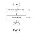
第2の実施形態では、参照医用画像を使用せずに穿刺ルートを決定する例について、図19のフローチャートを参照しながら説明する。In the second embodiment, an example of determining a puncture route without using a reference medical image will be described with reference to the flowchart in FIG. 19.
ステップST31では、ユーザは、超音波プローブ2で被検体110の体内を走査しながら、最適な穿刺ルートを探索する作業を行う。In step ST31, the user searches for the optimal puncture route while scanning the inside of the subject 110 with the
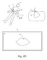
図20はステップST31の説明図である。
ステップS31では、ユーザは超音波プローブ2を被検体110の体表面に当接させて超音波の送受信を開始する。そして、プロセッサ7は、エコー信号に基づいて作成された超音波画像UGを前記表示部8に表示させる。超音波画像UGは画像表示領域8cに表示される。超音波画像UGは例えばBモード画像である。
次に、ユーザは、超音波プローブ2で被検体110の体内を走査しながら、ターゲット(例えば、腫瘍)にアクセスするための穿刺ルート(例えば、穿刺針を刺入する位置及び刺入角度)を探索する。 FIG. 20 is an explanatory diagram of step ST31.
In step S31, the user brings the
Next, the user searches for a puncture route (eg, the position and angle at which the puncture needle is inserted) for accessing a target (eg, a tumor) while scanning the inside of the subject 110 with the
図21は、穿刺ルートを探索するときの説明図である。
ユーザは、プローブ2を操作し、穿刺ルートを探索する。図21では、ユーザは、超音波の送受信領域60に対応する被検体110の領域61(グレーでハイライトされた部分)に、最適な穿刺ルートを発見することができた例が示されている。ユーザは、最適な穿刺ルートが得られる領域61を探索することができたら、ステップST32に進む。 FIG. 21 is an explanatory diagram for searching for a puncture route.
The user operates the
ステップST32では、ユーザは、ユーザインターフェース10を操作して、最適な穿刺ルートが得られる領域61の対応点B1、B2、およびB3の位置情報を記憶させるための命令を入力する。この命令が入力されると、プロセッサ7は、対応点B1、B2、およびB3の位置情報を、超音波画像UGの座標系の位置情報として記憶する。In step ST32, the user operates the
つまり、第2の実施形態では、プロセッサ7は、点C1、C2、およびC3の位置情報を、参照医用画像のボリュームデータVDではなく、超音波画像UGの座標系における位置情報として記憶する。In other words, in the second embodiment, the
最適な穿刺ルートが得られる領域61の対応点B1、B2、およびB3の位置情報を記憶した後、ユーザは穿刺作業を行う。穿刺作業については、図9のフローを参照しながら説明する。尚、第2の実施形態では、ステップS32で穿刺針を刺入する位置及び刺入角度を決めてから、穿刺作業を開始するまで、被検体110は動いておらず、同じ位置に留まっているものとする。After storing the position information of the corresponding points B1, B2, and B3 in the
ステップST20では、ユーザは、被検体110をプローブ2で操作して、最適な穿刺ルートが得られる領域61(図21参照)を再び見つけ出すための作業を行う。
尚、第2の実施形態におけるステップST20は、第1の実施形態と基本的に共通しているので、ステップST20について以下に簡単に説明する。 In step ST20, the user manipulates the subject 110 with the
Since step ST20 in the second embodiment is basically the same as in the first embodiment, step ST20 will be briefly described below.
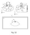
ステップST11において、プロセッサ7は、表示部8にインジケータId1を表示させる。図22は、表示部8に表示されたインジケータId1を示す図である。インジケータId1は、点C1と点E1との間の距離を示している。第1の実施形態では、インジケータId1は参照医用画像71に重なるように表示されていたが(図11参照)、第2の実施形態では、インジケータId1は、超音波画像70に重なるように表示される。インジケータId1を表示させたら、ステップST12に進む。In step ST11, the
ステップST12では、ユーザは、インジケータId1を見ながら、点C1の位置合わせを行う。図23に示すように、インジケータId1が「+」の表示形態に変化したら、ステップST13に進む。In step ST12, the user aligns point C1 while looking at indicator Id1. When indicator Id1 changes to a "+" display form as shown in FIG. 23, proceed to step ST13.
ステップST13では、次のインジケータId2が表示される。図24は、表示部8に表示されたインジケータId2を示す図である。インジケータId2は、点C2と点E2との間の距離を示している。インジケータId2を表示させたら、ステップST14に進む。In step ST13, the next indicator Id2 is displayed. FIG. 24 is a diagram showing the indicator Id2 displayed on the
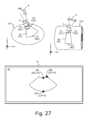
ステップST14では、ユーザは、インジケータId2を見ながら、プローブ2を回転させて点C2の位置合わせを行う。図25に示すように、インジケータId2が「+」の表示形態に変化したら、ステップST15に進む。In step ST14, the user rotates the
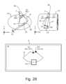
ステップST15では、次のインジケータId3が表示される。図26は、表示部8に表示されたインジケータId3を示す図である。インジケータId3は、点C3と点E3との間の距離を示している。インジケータId3を表示させたら、ステップST16に進む。In step ST15, the next indicator Id3 is displayed. FIG. 26 is a diagram showing the indicator Id3 displayed on the
ステップST16では、ユーザは、インジケータId3を見ながら、プローブ2の傾き角を調整して点C3の位置合わせを行う。図27に示すように、インジケータId3が「+」の表示形態に変化したら、ステップST21に進み、ユーザは、表示部8に表示された超音波画像を参照しながら、被検体110に実際に穿刺を行い、フローを終了する。In step ST16, the user adjusts the tilt angle of the
第2の実施形態の超音波診断装置1によっても第1の実施形態と同一の効果を得ることができる。また、第2の実施形態では、参照医用画像のボリュームデータVDではなく、超音波画像UGの座標系における位置情報が記憶されるので、参照医用画像の座標系と超音波画像の座標系とを対応付ける作業が不要となり、ユーザの作業負担を軽減することができる。The ultrasound
1 超音波診断装置
2 超音波プローブ
2a 振動素子
2b プローブ面
2c 中央部
2d、2f 端部
2e 中心軸
3 送信ビームフォーマ
4 送信器
5 受信器
6 受信ビームフォーマ
7 プロセッサ
8 表示部
8a、8b、8c 画像表示領域
9 メモリ
10 ユーザインターフェース
11 磁気発生部
12 磁気センサ
60 送受信領域
61 領域
62 垂直面
70 超音波画像
71 参照医用画像
100 医用画像装置
110 被検体
111 断面REFERENCE SIGNS
Claims (16)
Translated fromJapanese表示部と、
少なくとも1つのプロセッサと
を含む超音波診断装置であって、
前記少なくとも1つのプロセッサは、
被検体の前記送受信領域に対応する第1の領域の位置情報をメモリに記憶させることであって、前記被検体の第1の領域は、前記第1の点に対応する第1の対応点と、前記第2の点に対応する第2の対応点と、前記第3の点に対応する第3の対応点とを含み、前記第1の対応点、前記第2の対応点、および前記第3の対応点の位置情報をメモリに記憶させること、
前記第1の対応点、前記第2の対応点、および前記第3の対応点の位置情報を記憶した後、リアルタイムの超音波の送受信領域の前記第1の点と前記第1の対応点との間の第1の距離を示す第1のインジケータを表示部に表示させること、
第1のインジケータが、前記第1の距離が零であることを示す表示態様に変化した後で、リアルタイムの前記プローブの超音波の送受信領域の前記第2の点と前記第2の対応点との間の第2の距離を示す第2のインジケータを表示部に表示させること、
前記第2のインジケータが、前記第2の距離が零であることを示す表示態様に変化した後で、リアルタイムの超音波の送受信領域の前記第3の点と前記第3の対応点との間の第3の距離を示す第3のインジケータを表示部に表示させること
を実行する、超音波診断装置。
A probe, the ultrasonic transmission/reception region of the probe including a first point, a second point different from the first point, and a third point different from the first and second points;
A display unit;
at least one processor,
The at least one processor
storing position information of a first region ofa subject corresponding to the transmitting/receiving region in a memory, the first region of the subject including a first corresponding point corresponding to the first point, a second corresponding point corresponding to the second point, and a third corresponding point corresponding to the third point, and storing position information of the first corresponding point, the second corresponding point, and the third corresponding point in a memory;
displaying, on a display unit, a first indicator indicating a first distance between the first point and the first corresponding point in a transmission/reception region of ultrasonic waves in real time, after storing position information of the first corresponding point, the second corresponding point, and the third corresponding point;
displaying, on a display unit, a second indicator indicating a second distance between the second point and the second corresponding point in a transmission/reception region of ultrasonic waves of the probe in real time after the first indicator has changed to a display mode indicating that the first distance is zero;
and after the second indicator changes to a display mode indicating that the second distance is zero, a third indicator indicating a third distance between the third point in a real-time ultrasonic transmission/reception area and the third corresponding point is displayed on a display unit.
The ultrasonic diagnostic device according to claim 1 , wherein position information of the first corresponding point, the second corresponding point, and the third corresponding point is stored as position information in a coordinate system of an ultrasonic image acquired by the ultrasonicdiagnostic device.
The ultrasound diagnostic apparatus according to claim 1 , wherein the at least one processor causes amedical image to be displayed on a display unit.
The ultrasonic diagnostic apparatus according to claim 1 , wherein the first point corresponds to a first portion ofa probe surface.
前記第3の点は、前記プローブの送受信領域の深部に対応する点である、請求項6に記載の超音波診断装置。 the second point corresponds to a second portion of the probe surface;
The ultrasonic diagnostic apparatus according to claim 6 , wherein the third point corresponds to a deep portion of a transmitting/receiving region of the probe.
前記第3の点は、前記プローブ面の第2の部分に対応する点である、請求項6に記載の超音波診断装置。 the second point corresponds to a deep portion of a transmitting/receiving region of the probe;
The ultrasonic diagnostic apparatus according to claim 6 , wherein the third point corresponds to a second portion of the probe surface.
表示部と、
少なくとも1つのプロセッサと
を含む超音波診断装置に含まれる記憶媒体であって、
被検体の前記送受信領域に対応する第1の領域は、前記第1の点に対応する第1の対応点と、前記第2の点に対応する第2の対応点と、前記第3の点に対応する第3の対応点とを含み、
前記記憶媒体は、前記少なくとも1つのプロセッサに実行される命令を記憶しており、前記命令は、前記少なくとも1つのプロセッサに、
前記第1の対応点、前記第2の対応点、および前記第3の対応点の位置情報を前記記憶媒体又は他の記憶媒体に記憶させること、
前記第1の対応点、前記第2の対応点、および前記第3の対応点の位置情報を記憶した後、リアルタイムの超音波の送受信領域の前記第1の点と前記第1の対応点との間の第1の距離を示す第1のインジケータを表示部に表示させること、
第1のインジケータが、前記第1の距離が零であることを示す表示態様に変化した後で、リアルタイムの前記プローブの超音波の送受信領域の前記第2の点と前記第2の対応点との間の第2の距離を示す第2のインジケータを表示部に表示させること、
前記第2のインジケータが、前記第2の距離が零であることを示す表示態様に変化した後で、リアルタイムの超音波の送受信領域の前記第3の点と前記第3の対応点との間の第3の距離を示す第3のインジケータを表示部に表示させること
を実行させる、記憶媒体。 A probe, the ultrasonic transmission/reception region of the probe including a first point, a second point different from the first point, and a third point different from the first and second points;
A display unit;
At least one processor.
a first region corresponding to the transmission/reception region ofthe subject includes a first corresponding point corresponding to the first point, a second corresponding point corresponding to the second point, and a third corresponding point corresponding to the third point;
The storage medium stores instructions for execution by the at least one processor, the instructions causing the at least one processor to:
storing position information of the first corresponding point, the second corresponding point, and the third corresponding point in the storage medium or another storage medium;
displaying, on a display unit, a first indicator indicating a first distance between the first point and the first corresponding point in a transmission/reception region of ultrasonic waves in real time, after storing position information of the first corresponding point, the second corresponding point, and the third corresponding point;
displaying, on a display unit, a second indicator indicating a second distance between the second point and the second corresponding point in a transmission/reception region of ultrasonic waves of the probe in real time after the first indicator has changed to a display mode indicating that the first distance is zero;
A storage medium that causes a display unit to display a third indicator indicating a third distance between the third point in the real-time ultrasonic transmission/reception area and the third corresponding point after the second indicator changes to a display mode indicating that the second distance is zero.
Priority Applications (2)
| Application Number | Priority Date | Filing Date | Title |
|---|---|---|---|
| JP2023101164AJP7589294B1 (en) | 2023-06-20 | 2023-06-20 | Ultrasound diagnostic device and storage medium |
| CN202410799255.2ACN119157565A (en) | 2023-06-20 | 2024-06-20 | Ultrasonic diagnostic device and storage medium |
Applications Claiming Priority (1)
| Application Number | Priority Date | Filing Date | Title |
|---|---|---|---|
| JP2023101164AJP7589294B1 (en) | 2023-06-20 | 2023-06-20 | Ultrasound diagnostic device and storage medium |
Publications (2)
| Publication Number | Publication Date |
|---|---|
| JP7589294B1true JP7589294B1 (en) | 2024-11-25 |
| JP2025001531A JP2025001531A (en) | 2025-01-08 |
Family
ID=93588017
Family Applications (1)
| Application Number | Title | Priority Date | Filing Date |
|---|---|---|---|
| JP2023101164AActiveJP7589294B1 (en) | 2023-06-20 | 2023-06-20 | Ultrasound diagnostic device and storage medium |
Country Status (2)
| Country | Link |
|---|---|
| JP (1) | JP7589294B1 (en) |
| CN (1) | CN119157565A (en) |
Citations (3)
| Publication number | Priority date | Publication date | Assignee | Title |
|---|---|---|---|---|
| WO2006059668A1 (en) | 2004-12-03 | 2006-06-08 | Hitachi Medical Corporation | Ultrasonic device, ultrasonic imaging program, and ultrasonic imaging method |
| JP2013070794A (en) | 2011-09-27 | 2013-04-22 | Ge Medical Systems Global Technology Co Llc | Ultrasonic diagnostic apparatus and control program of the same |
| JP2017196129A (en) | 2016-04-27 | 2017-11-02 | ゼネラル・エレクトリック・カンパニイ | Ultrasound image display apparatus and control program therefor |
- 2023
- 2023-06-20JPJP2023101164Apatent/JP7589294B1/enactiveActive
- 2024
- 2024-06-20CNCN202410799255.2Apatent/CN119157565A/enactivePending
Patent Citations (4)
| Publication number | Priority date | Publication date | Assignee | Title |
|---|---|---|---|---|
| WO2006059668A1 (en) | 2004-12-03 | 2006-06-08 | Hitachi Medical Corporation | Ultrasonic device, ultrasonic imaging program, and ultrasonic imaging method |
| JP2010051817A (en) | 2004-12-03 | 2010-03-11 | Hitachi Medical Corp | Ultrasonic device, ultrasonic imaging program and ultrasonic imaging method |
| JP2013070794A (en) | 2011-09-27 | 2013-04-22 | Ge Medical Systems Global Technology Co Llc | Ultrasonic diagnostic apparatus and control program of the same |
| JP2017196129A (en) | 2016-04-27 | 2017-11-02 | ゼネラル・エレクトリック・カンパニイ | Ultrasound image display apparatus and control program therefor |
Also Published As
| Publication number | Publication date |
|---|---|
| JP2025001531A (en) | 2025-01-08 |
| CN119157565A (en) | 2024-12-20 |
Similar Documents
| Publication | Publication Date | Title |
|---|---|---|
| US6500123B1 (en) | Methods and systems for aligning views of image data | |
| JP6274421B2 (en) | Ultrasonic diagnostic apparatus and control program therefor | |
| JP6873647B2 (en) | Ultrasonic diagnostic equipment and ultrasonic diagnostic support program | |
| US11109839B2 (en) | Imaging systems and methods for positioning a 3D ultrasound volume in a desired orientation | |
| US10368841B2 (en) | Ultrasound diagnostic apparatus | |
| JP6615603B2 (en) | Medical image diagnostic apparatus and medical image diagnostic program | |
| JP6097452B2 (en) | Ultrasonic imaging system and ultrasonic imaging method | |
| US20090069679A1 (en) | Ultrasound diagnostic apparatus | |
| KR102607013B1 (en) | Ultrasound imaging apparatus and control method for the same | |
| JP6956483B2 (en) | Ultrasonic diagnostic equipment and scanning support program | |
| JP2009089736A (en) | Ultrasonic diagnostic equipment | |
| JP5601684B2 (en) | Medical imaging device | |
| JP5682873B2 (en) | Ultrasonic diagnostic equipment | |
| EP2921116B1 (en) | Medical image display apparatus, method, and program | |
| US12369892B2 (en) | Ultrasound diagnosis apparatus and medical image processing method | |
| US20150351725A1 (en) | Ultrasonic diagnosis apparatus and medical image processing apparatus | |
| JP7589294B1 (en) | Ultrasound diagnostic device and storage medium | |
| JP5202916B2 (en) | Ultrasound image diagnostic apparatus and control program thereof | |
| JP2001017433A (en) | Ultrasonic diagnostic device and ultrasonic image display device | |
| JP2021023697A (en) | Ultrasonic diagnostic device and ultrasonic image processing method | |
| JPH10216127A (en) | Ultrasonic diagnostic apparatus and adapter device for image processing | |
| JP6878042B2 (en) | Ultrasonic diagnostic equipment and ultrasonic diagnostic support program | |
| JP2006346176A (en) | Ultrasonic diagnostic apparatus and image display apparatus | |
| JP3040306U (en) | Ultrasonic diagnostic device and its image processing adapter device |
Legal Events
| Date | Code | Title | Description |
|---|---|---|---|
| A621 | Written request for application examination | Free format text:JAPANESE INTERMEDIATE CODE: A621 Effective date:20230622 | |
| A131 | Notification of reasons for refusal | Free format text:JAPANESE INTERMEDIATE CODE: A131 Effective date:20240515 | |
| A521 | Request for written amendment filed | Free format text:JAPANESE INTERMEDIATE CODE: A523 Effective date:20240814 | |
| TRDD | Decision of grant or rejection written | ||
| A01 | Written decision to grant a patent or to grant a registration (utility model) | Free format text:JAPANESE INTERMEDIATE CODE: A01 Effective date:20241016 | |
| A61 | First payment of annual fees (during grant procedure) | Free format text:JAPANESE INTERMEDIATE CODE: A61 Effective date:20241113 | |
| R150 | Certificate of patent or registration of utility model | Ref document number:7589294 Country of ref document:JP Free format text:JAPANESE INTERMEDIATE CODE: R150 |