JP7589229B2 - Surgical Instrument Wearable Display System - Google Patents
Surgical Instrument Wearable Display SystemDownload PDFInfo
- Publication number
- JP7589229B2 JP7589229B2JP2022507853AJP2022507853AJP7589229B2JP 7589229 B2JP7589229 B2JP 7589229B2JP 2022507853 AJP2022507853 AJP 2022507853AJP 2022507853 AJP2022507853 AJP 2022507853AJP 7589229 B2JP7589229 B2JP 7589229B2
- Authority
- JP
- Japan
- Prior art keywords
- imaging device
- medical imaging
- surgical instrument
- ray
- display
- Prior art date
- Legal status (The legal status is an assumption and is not a legal conclusion. Google has not performed a legal analysis and makes no representation as to the accuracy of the status listed.)
- Active
Links
- 238000002059diagnostic imagingMethods0.000claimsdescription178
- 210000003484anatomyAnatomy0.000claimsdescription98
- 238000000034methodMethods0.000claimsdescription78
- 230000000007visual effectEffects0.000claimsdescription70
- 210000000988bone and boneAnatomy0.000claimsdescription38
- 238000004891communicationMethods0.000claimsdescription22
- 230000033001locomotionEffects0.000claimsdescription20
- 230000004044responseEffects0.000claimsdescription17
- 230000008859changeEffects0.000claimsdescription9
- 238000005553drillingMethods0.000description33
- 238000003384imaging methodMethods0.000description30
- 238000012545processingMethods0.000description15
- 230000001054cortical effectEffects0.000description12
- 239000007943implantSubstances0.000description11
- 238000002594fluoroscopyMethods0.000description9
- 230000008569processEffects0.000description9
- 230000003213activating effectEffects0.000description6
- 238000003708edge detectionMethods0.000description6
- 230000005540biological transmissionEffects0.000description4
- 238000001356surgical procedureMethods0.000description4
- 238000013459approachMethods0.000description3
- 238000010586diagramMethods0.000description3
- 230000005484gravityEffects0.000description3
- 239000000463materialSubstances0.000description3
- 210000004872soft tissueAnatomy0.000description3
- 238000004873anchoringMethods0.000description2
- 230000006870functionEffects0.000description2
- 238000005259measurementMethods0.000description2
- 239000003826tabletSubstances0.000description2
- 208000032767Device breakageDiseases0.000description1
- 230000009471actionEffects0.000description1
- 230000004913activationEffects0.000description1
- 238000007792additionMethods0.000description1
- 230000008901benefitEffects0.000description1
- 230000001934delayEffects0.000description1
- 230000003111delayed effectEffects0.000description1
- 238000009429electrical wiringMethods0.000description1
- 238000005516engineering processMethods0.000description1
- 230000001815facial effectEffects0.000description1
- 210000000527greater trochanterAnatomy0.000description1
- 230000002452interceptive effectEffects0.000description1
- 210000000528lesser trochanterAnatomy0.000description1
- 230000007246mechanismEffects0.000description1
- 238000012986modificationMethods0.000description1
- 230000004048modificationEffects0.000description1
- 238000012544monitoring processMethods0.000description1
- 230000003287optical effectEffects0.000description1
- 239000013307optical fiberSubstances0.000description1
- 238000007747platingMethods0.000description1
- 230000009467reductionEffects0.000description1
- 230000008439repair processEffects0.000description1
- 230000002207retinal effectEffects0.000description1
Images


Classifications
- A—HUMAN NECESSITIES
- A61—MEDICAL OR VETERINARY SCIENCE; HYGIENE
- A61B—DIAGNOSIS; SURGERY; IDENTIFICATION
- A61B6/00—Apparatus or devices for radiation diagnosis; Apparatus or devices for radiation diagnosis combined with radiation therapy equipment
- A61B6/44—Constructional features of apparatus for radiation diagnosis
- A61B6/4429—Constructional features of apparatus for radiation diagnosis related to the mounting of source units and detector units
- A61B6/4435—Constructional features of apparatus for radiation diagnosis related to the mounting of source units and detector units the source unit and the detector unit being coupled by a rigid structure
- A61B6/4441—Constructional features of apparatus for radiation diagnosis related to the mounting of source units and detector units the source unit and the detector unit being coupled by a rigid structure the rigid structure being a C-arm or U-arm
- A—HUMAN NECESSITIES
- A61—MEDICAL OR VETERINARY SCIENCE; HYGIENE
- A61B—DIAGNOSIS; SURGERY; IDENTIFICATION
- A61B17/00—Surgical instruments, devices or methods
- A61B17/16—Instruments for performing osteoclasis; Drills or chisels for bones; Trepans
- A61B17/1613—Component parts
- A61B17/1626—Control means; Display units
- A—HUMAN NECESSITIES
- A61—MEDICAL OR VETERINARY SCIENCE; HYGIENE
- A61B—DIAGNOSIS; SURGERY; IDENTIFICATION
- A61B17/00—Surgical instruments, devices or methods
- A61B17/16—Instruments for performing osteoclasis; Drills or chisels for bones; Trepans
- A61B17/17—Guides or aligning means for drills, mills, pins or wires
- A61B17/1703—Guides or aligning means for drills, mills, pins or wires using imaging means, e.g. by X-rays
- A—HUMAN NECESSITIES
- A61—MEDICAL OR VETERINARY SCIENCE; HYGIENE
- A61B—DIAGNOSIS; SURGERY; IDENTIFICATION
- A61B17/00—Surgical instruments, devices or methods
- A61B17/16—Instruments for performing osteoclasis; Drills or chisels for bones; Trepans
- A61B17/17—Guides or aligning means for drills, mills, pins or wires
- A61B17/1725—Guides or aligning means for drills, mills, pins or wires for applying transverse screws or pins through intramedullary nails or pins
- A—HUMAN NECESSITIES
- A61—MEDICAL OR VETERINARY SCIENCE; HYGIENE
- A61B—DIAGNOSIS; SURGERY; IDENTIFICATION
- A61B34/00—Computer-aided surgery; Manipulators or robots specially adapted for use in surgery
- A61B34/25—User interfaces for surgical systems
- A—HUMAN NECESSITIES
- A61—MEDICAL OR VETERINARY SCIENCE; HYGIENE
- A61B—DIAGNOSIS; SURGERY; IDENTIFICATION
- A61B6/00—Apparatus or devices for radiation diagnosis; Apparatus or devices for radiation diagnosis combined with radiation therapy equipment
- A61B6/12—Arrangements for detecting or locating foreign bodies
- A—HUMAN NECESSITIES
- A61—MEDICAL OR VETERINARY SCIENCE; HYGIENE
- A61B—DIAGNOSIS; SURGERY; IDENTIFICATION
- A61B6/00—Apparatus or devices for radiation diagnosis; Apparatus or devices for radiation diagnosis combined with radiation therapy equipment
- A61B6/46—Arrangements for interfacing with the operator or the patient
- A61B6/461—Displaying means of special interest
- A61B6/462—Displaying means of special interest characterised by constructional features of the display
- A—HUMAN NECESSITIES
- A61—MEDICAL OR VETERINARY SCIENCE; HYGIENE
- A61B—DIAGNOSIS; SURGERY; IDENTIFICATION
- A61B6/00—Apparatus or devices for radiation diagnosis; Apparatus or devices for radiation diagnosis combined with radiation therapy equipment
- A61B6/54—Control of apparatus or devices for radiation diagnosis
- A61B6/547—Control of apparatus or devices for radiation diagnosis involving tracking of position of the device or parts of the device
- A—HUMAN NECESSITIES
- A61—MEDICAL OR VETERINARY SCIENCE; HYGIENE
- A61B—DIAGNOSIS; SURGERY; IDENTIFICATION
- A61B90/00—Instruments, implements or accessories specially adapted for surgery or diagnosis and not covered by any of the groups A61B1/00 - A61B50/00, e.g. for luxation treatment or for protecting wound edges
- A61B90/36—Image-producing devices or illumination devices not otherwise provided for
- A61B90/37—Surgical systems with images on a monitor during operation
- A—HUMAN NECESSITIES
- A61—MEDICAL OR VETERINARY SCIENCE; HYGIENE
- A61B—DIAGNOSIS; SURGERY; IDENTIFICATION
- A61B17/00—Surgical instruments, devices or methods
- A61B2017/00017—Electrical control of surgical instruments
- A61B2017/00022—Sensing or detecting at the treatment site
- A61B2017/00075—Motion
- A—HUMAN NECESSITIES
- A61—MEDICAL OR VETERINARY SCIENCE; HYGIENE
- A61B—DIAGNOSIS; SURGERY; IDENTIFICATION
- A61B17/00—Surgical instruments, devices or methods
- A61B2017/00017—Electrical control of surgical instruments
- A61B2017/00199—Electrical control of surgical instruments with a console, e.g. a control panel with a display
- A—HUMAN NECESSITIES
- A61—MEDICAL OR VETERINARY SCIENCE; HYGIENE
- A61B—DIAGNOSIS; SURGERY; IDENTIFICATION
- A61B17/00—Surgical instruments, devices or methods
- A61B2017/00017—Electrical control of surgical instruments
- A61B2017/00203—Electrical control of surgical instruments with speech control or speech recognition
- A—HUMAN NECESSITIES
- A61—MEDICAL OR VETERINARY SCIENCE; HYGIENE
- A61B—DIAGNOSIS; SURGERY; IDENTIFICATION
- A61B17/00—Surgical instruments, devices or methods
- A61B2017/00017—Electrical control of surgical instruments
- A61B2017/00221—Electrical control of surgical instruments with wireless transmission of data, e.g. by infrared radiation or radiowaves
- A—HUMAN NECESSITIES
- A61—MEDICAL OR VETERINARY SCIENCE; HYGIENE
- A61B—DIAGNOSIS; SURGERY; IDENTIFICATION
- A61B34/00—Computer-aided surgery; Manipulators or robots specially adapted for use in surgery
- A61B34/10—Computer-aided planning, simulation or modelling of surgical operations
- A61B2034/107—Visualisation of planned trajectories or target regions
- A—HUMAN NECESSITIES
- A61—MEDICAL OR VETERINARY SCIENCE; HYGIENE
- A61B—DIAGNOSIS; SURGERY; IDENTIFICATION
- A61B34/00—Computer-aided surgery; Manipulators or robots specially adapted for use in surgery
- A61B34/20—Surgical navigation systems; Devices for tracking or guiding surgical instruments, e.g. for frameless stereotaxis
- A61B2034/2046—Tracking techniques
- A61B2034/2048—Tracking techniques using an accelerometer or inertia sensor
- A—HUMAN NECESSITIES
- A61—MEDICAL OR VETERINARY SCIENCE; HYGIENE
- A61B—DIAGNOSIS; SURGERY; IDENTIFICATION
- A61B34/00—Computer-aided surgery; Manipulators or robots specially adapted for use in surgery
- A61B34/25—User interfaces for surgical systems
- A61B2034/252—User interfaces for surgical systems indicating steps of a surgical procedure
- A—HUMAN NECESSITIES
- A61—MEDICAL OR VETERINARY SCIENCE; HYGIENE
- A61B—DIAGNOSIS; SURGERY; IDENTIFICATION
- A61B90/00—Instruments, implements or accessories specially adapted for surgery or diagnosis and not covered by any of the groups A61B1/00 - A61B50/00, e.g. for luxation treatment or for protecting wound edges
- A61B90/06—Measuring instruments not otherwise provided for
- A61B2090/062—Measuring instruments not otherwise provided for penetration depth
- A—HUMAN NECESSITIES
- A61—MEDICAL OR VETERINARY SCIENCE; HYGIENE
- A61B—DIAGNOSIS; SURGERY; IDENTIFICATION
- A61B90/00—Instruments, implements or accessories specially adapted for surgery or diagnosis and not covered by any of the groups A61B1/00 - A61B50/00, e.g. for luxation treatment or for protecting wound edges
- A61B90/36—Image-producing devices or illumination devices not otherwise provided for
- A61B90/37—Surgical systems with images on a monitor during operation
- A61B2090/372—Details of monitor hardware
- A—HUMAN NECESSITIES
- A61—MEDICAL OR VETERINARY SCIENCE; HYGIENE
- A61B—DIAGNOSIS; SURGERY; IDENTIFICATION
- A61B90/00—Instruments, implements or accessories specially adapted for surgery or diagnosis and not covered by any of the groups A61B1/00 - A61B50/00, e.g. for luxation treatment or for protecting wound edges
- A61B90/36—Image-producing devices or illumination devices not otherwise provided for
- A61B90/37—Surgical systems with images on a monitor during operation
- A61B2090/376—Surgical systems with images on a monitor during operation using X-rays, e.g. fluoroscopy
- A—HUMAN NECESSITIES
- A61—MEDICAL OR VETERINARY SCIENCE; HYGIENE
- A61B—DIAGNOSIS; SURGERY; IDENTIFICATION
- A61B34/00—Computer-aided surgery; Manipulators or robots specially adapted for use in surgery
- A61B34/20—Surgical navigation systems; Devices for tracking or guiding surgical instruments, e.g. for frameless stereotaxis
- A—HUMAN NECESSITIES
- A61—MEDICAL OR VETERINARY SCIENCE; HYGIENE
- A61B—DIAGNOSIS; SURGERY; IDENTIFICATION
- A61B90/00—Instruments, implements or accessories specially adapted for surgery or diagnosis and not covered by any of the groups A61B1/00 - A61B50/00, e.g. for luxation treatment or for protecting wound edges
- A61B90/10—Instruments, implements or accessories specially adapted for surgery or diagnosis and not covered by any of the groups A61B1/00 - A61B50/00, e.g. for luxation treatment or for protecting wound edges for stereotaxic surgery, e.g. frame-based stereotaxis
- A61B90/11—Instruments, implements or accessories specially adapted for surgery or diagnosis and not covered by any of the groups A61B1/00 - A61B50/00, e.g. for luxation treatment or for protecting wound edges for stereotaxic surgery, e.g. frame-based stereotaxis with guides for needles or instruments, e.g. arcuate slides or ball joints
Landscapes
- Health & Medical Sciences (AREA)
- Life Sciences & Earth Sciences (AREA)
- Surgery (AREA)
- Engineering & Computer Science (AREA)
- Medical Informatics (AREA)
- Nuclear Medicine, Radiotherapy & Molecular Imaging (AREA)
- General Health & Medical Sciences (AREA)
- Heart & Thoracic Surgery (AREA)
- Molecular Biology (AREA)
- Animal Behavior & Ethology (AREA)
- Public Health (AREA)
- Veterinary Medicine (AREA)
- Biomedical Technology (AREA)
- Oral & Maxillofacial Surgery (AREA)
- Pathology (AREA)
- Radiology & Medical Imaging (AREA)
- Orthopedic Medicine & Surgery (AREA)
- Dentistry (AREA)
- High Energy & Nuclear Physics (AREA)
- Optics & Photonics (AREA)
- Biophysics (AREA)
- Physics & Mathematics (AREA)
- Human Computer Interaction (AREA)
- Robotics (AREA)
- Gynecology & Obstetrics (AREA)
- Apparatus For Radiation Diagnosis (AREA)
- Surgical Instruments (AREA)
Description
Translated fromJapanese本発明は、医療用撮像と併せて使用され得るシステムに関する。The present invention relates to a system that can be used in conjunction with medical imaging.
Cアーム又は移動増強装置は、X線技術に基づく医療用撮像装置の一例である。Cアームという名前は、X線源とX線検出器とを互いに接続するために使用されるC字形状のアームに由来している。Cアーム装置などの様々な医療用撮像装置は、モニタ上に連続的なX線画像を示すタイプの医療用撮像であるX線透視法を実施することができる。X線透視法による処置中、X線源又はトランスミッタは、患者の身体を貫通するX線を放射する。X線検出器又は画像増強装置は、身体を通過するX線を、医療用撮像装置のモニタ上に表示される可視画像に変換する。Cアーム装置などの医療用撮像装置は、リアルタイムで高解像度X線画像を表示することができるため、医師は、手術中のいかなるときにも進行を監視することができ、したがって、表示された画像に基づいて適切な措置を取ることができる。しかしながら、画像を監視することは、特定の処置中、例えば、患者の解剖学的構造だけでなく、医療用撮像装置のディスプレイにも注意を払わなければならない処置中、困難となることが多い。更に、患者に対してCアームを調整して、壁内釘のねじ孔の位置を特定することは、困難となり、かつ時間を要することになり得る。ねじが真円に見えるようにCアームをねじ孔の軸線とフリーハンドで位置合わせさせることは、他の問題の中でも、とりわけ、不必要な放射線照射、費用がかかる稼働時間、及びストレスをもたらし得る共通のプロセスである。A C-arm or mobile intensifier is an example of a medical imaging device based on X-ray technology. The name C-arm comes from the C-shaped arm used to connect the X-ray source and the X-ray detector together. Various medical imaging devices, such as C-arm devices, can perform fluoroscopy, a type of medical imaging that shows continuous X-ray images on a monitor. During a fluoroscopy procedure, an X-ray source or transmitter emits X-rays that penetrate the patient's body. An X-ray detector or image intensifier converts the X-rays that pass through the body into a visible image that is displayed on the monitor of the medical imaging device. Medical imaging devices, such as C-arm devices, can display high-resolution X-ray images in real time, allowing the physician to monitor progress at any time during the procedure and therefore take appropriate action based on the displayed images. However, monitoring the images is often difficult during certain procedures, such as those that require attention to not only the patient's anatomy but also the display of the medical imaging device. Additionally, adjusting the C-arm to the patient to locate the screw holes for intramural nails can be difficult and time-consuming. Freehand aligning the C-arm with the axis of the screw hole so that the screw appears round is a common process that can result in unnecessary radiation exposure, costly operating time, and stress, among other problems.
一例では、外科用器具アセンブリは、プロセッサと、解剖学的構造に作用するように構成された外科用器具と、プロセッサに結合され、外科用器具に取り付けられたディスプレイと、を含む。ディスプレイは、解剖学的構造のX線透視データ、例えばX線画像又はビデオデータを表示するように構成され得る。X線透視データは、医療用撮像装置によって生成される。外科用器具アセンブリは、プロセッサと通信するメモリを更に含むことができる。メモリは、その中に命令を記憶してもよく、その命令は、プロセッサによって実行されると、外科用器具アセンブリに、例えば無線通信チャネルを介して、撮像装置からX線透視データをリアルタイムで受信させるようにするものである。更に、外科用器具は、近位端部と、その近位端部の反対側にある作業端部と、を含むことができる。作業端部は、解剖学的構造に作用するように構成され得るものであり、ディスプレイは、外科用器具の近位の場所から作業端部とディスプレイの両方への視線を提供するように配置され得る。更にまた、ディスプレイは、撮像装置のX線トランスミッタから撮像装置のX線レシーバへのX線の進行方向に対する、外科用器具の切断器具の位置合わせの可視指示を提供するように構成され得る。In one example, a surgical instrument assembly includes a processor, a surgical instrument configured to act on an anatomical structure, and a display coupled to the processor and attached to the surgical instrument. The display may be configured to display fluoroscopic data, e.g., x-ray images or video data, of the anatomical structure. The fluoroscopic data is generated by a medical imaging device. The surgical instrument assembly may further include a memory in communication with the processor. The memory may store instructions therein that, when executed by the processor, cause the surgical instrument assembly to receive fluoroscopic data in real time from the imaging device, e.g., via a wireless communication channel. Additionally, the surgical instrument may include a proximal end and a working end opposite the proximal end. The working end may be configured to act on the anatomical structure, and the display may be positioned to provide a line of sight to both the working end and the display from a location proximal to the surgical instrument. Furthermore, the display may be configured to provide a visual indication of the alignment of the cutting tool of the surgical instrument relative to the direction of travel of the x-rays from the x-ray transmitter of the imaging device to the x-ray receiver of the imaging device.
別の例では、外科用器具アセンブリは、髄内釘の同一性を決定するために、複数の髄内釘から髄内釘を識別することができる。髄内釘は、それぞれの係止ねじを受容するようにサイズ決めされた複数の係止孔を画定し得る。外科用器具アセンブリは、医療用撮像装置から第1のX線画像を受信し得る。第1のX線画像は、第1のX線画像が髄内釘の一部分を含むように、医療用撮像装置が第1の位置にあるときに、医療用撮像装置によって生成される。髄内釘の該一部分は、複数の係止孔のうちの少なくとも2つの係止孔の一部分を含む。少なくとも2つの係止孔の該一部分及び髄内釘の同一性に基づいて、外科用器具アセンブリは、医療用撮像装置が第1の位置とは異なる医療用撮像装置の第2の位置に配置され、該第2の位置から第2のX線画像を生成するとき、該第2のX線画像が、それぞれの円、例えば真円として示される少なくとも2つの係止孔を含むように、第2の位置を決定し得る。具体的に言えば、プロセッサは、円、例えば真円として示される髄内釘の孔を含むX線画像を医療用撮像装置が生成し得る、医療用撮像装置の位置を決定するように構成され得る。In another example, the surgical instrument assembly can identify an intramedullary nail from a plurality of intramedullary nails to determine an identity of the intramedullary nail. The intramedullary nail can define a plurality of locking holes sized to receive respective locking screws. The surgical instrument assembly can receive a first x-ray image from a medical imaging device. The first x-ray image is generated by the medical imaging device when the medical imaging device is in a first position such that the first x-ray image includes a portion of the intramedullary nail. The portion of the intramedullary nail includes a portion of at least two of the plurality of locking holes. Based on the portion of the at least two locking holes and the identity of the intramedullary nail, the surgical instrument assembly can determine a second position such that when the medical imaging device is placed in a second position of the medical imaging device different from the first position and generates a second x-ray image from the second position, the second x-ray image includes at least two locking holes shown as respective circles, e.g., perfect circles. Specifically, the processor may be configured to determine a position of the medical imaging device at which the medical imaging device may generate an X-ray image that includes the intramedullary nail hole shown as a circle, e.g., a perfect circle.
更に別の例において、外科用器具アセンブリの加速度計は、医療用撮像装置のX線発生器からX線レシーバへのX線の進行方向を用いて較正される。外科用器具アセンブリは、ドリルビットを有するドリルを含むことができる。外科用器具アセンブリは、医療用撮像装置によって生成された解剖学的構造のX線画像を表示することができる。X線画像は、標的部位を含むことができる。ドリルビットの先端部は解剖学的構造上に配置され得るものであり、外科用器具アセンブリは、標的部位と共にドリルビットの先端部の位置の表現を表示することができる。外科用器具アセンブリは、静止領域と、ドリルビットの配向を表現する可動インジケータとを含む配向画像を更に表示することができ、ドリルは、可動インジケータが静止領域に対する所定の空間的関係を有するときの、X線の進行方向に配向される。ドリルビットの先端部が標的部位と位置合わせされている間、かつ可動インジケータが静止領域に対する所定の空間的関係を有している間に、解剖学的構造が穿孔され得る。In yet another example, the accelerometer of the surgical instrument assembly is calibrated using a direction of travel of the x-rays from an x-ray generator to an x-ray receiver of the medical imaging device. The surgical instrument assembly can include a drill having a drill bit. The surgical instrument assembly can display an x-ray image of the anatomical structure generated by the medical imaging device. The x-ray image can include a target site. A tip of the drill bit can be positioned on the anatomical structure, and the surgical instrument assembly can display a representation of the position of the tip of the drill bit along with the target site. The surgical instrument assembly can further display an orientation image including a stationary region and a movable indicator representing an orientation of the drill bit, the drill being oriented in a direction of travel of the x-rays when the movable indicator has a predetermined spatial relationship to the stationary region. The anatomical structure can be drilled while the tip of the drill bit is aligned with the target site and while the movable indicator has a predetermined spatial relationship to the stationary region.
前述は、本開示の数個の態様を要約しており、本開示の完全な範囲を反映するものではない。本開示の更なる特徴及び利点は、以下の説明に示されているか、その説明から明らかになり得るか、又は本発明の実施により知ることができる。更に、前述の概要及び以下の詳細な説明はいずれも、例示及び説明するものであり、本開示の更なる説明を提供するよう意図されている。The foregoing summarizes several aspects of the present disclosure and does not reflect the complete scope of the present disclosure. Additional features and advantages of the present disclosure will be set forth in or will be obvious from the following description, or may be learned by the practice of the invention. Moreover, both the foregoing general description and the following detailed description are exemplary and explanatory and are intended to provide further explanation of the present disclosure.
前述の概要、並びに本開示の実施形態例の以下の詳細な説明は、添付の図面と共に読むことにより、よりよく理解されよう。本開示の実施形態例を図示する目的のために、図面が参照される。しかしながら、本出願が示される正確な配置及び手段に限定されないことを、理解しなければならない。
医療専門家は、患者に対して様々な医療処置を実施するために、医療用撮像装置、例えばCアーム装置を使用し得る。例えば、医療専門家は、骨折を判定し、外科的処置を案内し、又は外科修復の結果を検証するために、撮像装置を使用し得る。Cアーム装置は、連続的でリアルタイムの動画の生成を可能にする、例えば、スポット撮像及びX線透視撮像を提供する。このような画像は、Cアーム装置のディスプレイに提供される。本明細書では、場合によって、Cアームシステムのディスプレイが医療専門家を適切に支援するような様式で配置されていないことが認識されている。本明細書に記載される様々な実施形態において、撮像装置によって提供される画像は、外科用器具に装着され得るディスプレイにリアルタイムで送信され、それにより、撮像装置によって提供されるX線透視撮像は、外科用器具の作業端部を医療専門家が操作し、見ているときに、医療専門家によって見られ得る。ディスプレイは画像をリアルタイムで受信することができ、そのことで、画像が撮像装置によって生成されるのと同時に、画像がディスプレイによって表示される。一例では、ディスプレイは、撮像装置によって提供されるX線透視画像を髄内(IM)釘打ち処置中に見ることができるように、外科用ドリルに取り付けられる。一実施形態では、IM釘打ち処置中に医療専門家を案内するために、位置合わせの適用をも、外科用ドリルに装着されたディスプレイによって行うことができる。ディスプレイは対話型であってもよく、IM釘打ち処理の様々な態様を支援し得る。例えば、ディスプレイは、所与のIM釘の適切な進入点軌道を決定及び有効化すること、並びにIM釘のための遠位係止ねじの適切な配置及び配向を決定及び有効化することを補助し得る。A medical professional may use a medical imaging device, such as a C-arm device, to perform various medical procedures on a patient. For example, a medical professional may use an imaging device to determine a fracture, guide a surgical procedure, or verify the results of a surgical repair. The C-arm device provides, for example, spot imaging and fluoroscopic imaging, which allows for the generation of continuous, real-time moving images. Such images are provided on a display of the C-arm device. It is recognized herein that in some cases, the display of a C-arm system is not positioned in a manner that adequately assists the medical professional. In various embodiments described herein, images provided by the imaging device are transmitted in real time to a display that may be attached to a surgical instrument, such that fluoroscopic imaging provided by the imaging device may be viewed by the medical professional as the medical professional manipulates and views the working end of the surgical instrument. The display may receive images in real time, such that the images are displayed by the display at the same time that the images are generated by the imaging device. In one example, a display is attached to a surgical drill such that fluoroscopic images provided by the imaging device may be viewed during an intramedullary (IM) nailing procedure. In one embodiment, the application of alignment may also be performed by a display mounted on the surgical drill to guide the medical professional during the IM nailing procedure. The display may be interactive and may assist with various aspects of the IM nailing process. For example, the display may assist in determining and validating the proper entry point trajectory for a given IM nail, as well as determining and validating the proper placement and orientation of the distal locking screw for the IM nail.
最初に、X線透視法は連続的なX線画像をモニタ上に示すタイプの医療用撮像であるため、X線透視データ、X線透視画像、ビデオデータ、及びX線画像という用語は、別段の指定がない限り、本明細書では互換的に用いられ得るが、それに限定するものではない。したがって、X線画像は、X線ビームが患者の解剖学的構造を通過するX線透視処置中に生成された画像を指し得る。更に、X線透視データは、X線画像、ビデオデータ、又はコンピュータ生成視覚表現を含み得ることが理解されよう。したがって、X線透視データは、静止画又は動画を含み得る。First, because fluoroscopy is a type of medical imaging in which continuous x-ray images are shown on a monitor, the terms fluoroscopy data, fluoroscopy image, video data, and x-ray image may be used interchangeably herein, unless otherwise specified, but are not limited thereto. Thus, an x-ray image may refer to an image produced during a fluoroscopy procedure in which an x-ray beam passes through a patient's anatomy. Additionally, it will be understood that fluoroscopy data may include x-ray images, video data, or computer-generated visual representations. Thus, fluoroscopy data may include still or moving images.
図1を参照すると、医療用撮像システム102は、医療用撮像装置104と、撮像装置104と電気通信する外科用器具アセンブリ202と、を含み得る。Cアーム装置であり得る医療用撮像装置104は、身体(例えば骨)にX線を透過させように構成されたX線発生器又はトランスミッタ106と、X線トランスミッタ106からのX線を受信するように構成されたX線検出器又はレシーバ108と、を含み得る。したがって、医療用撮像装置104は、X線トランスミッタ106からX線レシーバ108へのX線の進行方向128を画定し得る。X線トランスミッタ106は、X線レシーバ108に面する平坦な表面106aを画定し得る。医療用撮像装置104は、X線トランスミッタ106をX線レシーバ108と物理的に接続するアーム110を更に含み得る。医療用撮像装置104は、医療用撮像装置104の位置を検出するように構成された運動センサ269を含み得る。運動センサ269は、例えば、X線の進行方向128の向きを検出するように構成されるように、例えば、トランスミッタ106上に、したがって医療用撮像装置104上に位置付けられ得る。上述のように、医療用撮像装置104は、Cアームとして構成され得る。したがって、運動センサ269は、Cアーム上に装着されてもよく、あるいは別様にCアームによって支持されてもよい。一例では、運動センサ269は、慣性測定ユニット(inertial measurement unit、IMU)として構成され得る。特に、例えば、運動センサ269は、トランスミッタ106の位置を検出するように構成されてもよく、したがって、トランスミッタ106の位置に基づいてX線の進行方向128を決定し得る。医療用撮像装置104は更に、X線検出器108からのX線画像を表示するように構成された医療用撮像装置ディスプレイ112と通信し得る。場合によっては、ディスプレイ112がアーム110に対して固定位置に位し得るように、医療用撮像装置ディスプレイ112はX線検出器108に物理的に組み込まれ得る。1, the
医療用撮像装置104は、開示される主題の説明を容易にするためにCアーム装置として提示されており、本開示の範囲を限定することを意図するものではない。更に、撮像システム102及び撮像装置104は、開示される主題の説明を容易にするために、それぞれ医療用撮像システム及び医療用撮像装置として提示されており、本開示の範囲を限定することを意図するものではない。したがって、システム102などのシステムに加えて、あるいはその代わりに、本明細書に開示される実施形態を実装するために、他の装置、システム、及び構成が用いられ得るが、そのような全ての実施形態は本開示の範囲内で企図されることが理解されよう。本明細書では、ディスプレイ112の位置が医療専門家にとっての問題を生じ得ることが認識されている。例えば、場合によっては、医療専門家は、X線発生器106とX線検出器108との間に配置された患者を見ながら、ディスプレイ112によってレンダリングされた画像又はデータを見ることが必要となり得る。一例では、医療専門家は、近位ねじの配置に使用される照準アームなどの補助器具又は誘導システムが不十分であることが原因で、IM釘打ち処置中に遠位側のロックねじを配置する課題に直面し得る。The
遠位ねじは一般に、X線透視の誘導下にてフリーハンド技術で挿入される。フリーハンド技術は一般的に、真円技術(perfect circle technique)と称される。フリーハンド技術を使用して、髄内(IM)釘の中にねじ孔を位置決めするために、髄内釘のX線画像が取得され得る。例を続けると、Cアーム及び/又は患者(したがって髄内釘)が調整され得、別のX線画像が取得され得る。目的のねじ孔がX線画像上で真円に見えるように、X線の進行方向128が目的のねじ孔に対して垂直となるまで、Cアーム及び/又は患者が調整され続けてもよく、X線画像が生成され続けてもよい。ねじ孔が円に見えるとき、外科医は、ねじの適切な穿孔の向きを決定することができる。試行錯誤によるアプローチと称され得るこのアプローチは、精度を欠くことがあり、撮像の時間及び量に関して高コストとなり、したがって、他の技術的な欠点の中でも、患者への不必要な放射線曝露をもたらし得ることが理解されよう。The distal screws are typically inserted with a freehand technique under fluoroscopic guidance. The freehand technique is commonly referred to as the perfect circle technique. Using the freehand technique, an x-ray image of the intramedullary (IM) nail may be acquired to position the screw holes in the IM nail. Continuing with the example, the C-arm and/or the patient (and thus the IM nail) may be adjusted and another x-ray image may be acquired. The C-arm and/or the patient may continue to be adjusted and x-ray images may continue to be generated until the
更に、IM釘打ち処置中に真円が確立されると、放射線画像を使用している間に視認性が不足するため、ドリルビットを遠位係止孔の軸線に適切に位置合わせすることが困難となり得る。不適切な位置合わせは、パイロット孔の穿孔中に埋没物の破壊又は亀裂を生じさせる可能性があり、このことは結果として、埋没物の破損、整復/固定不良、手術の遅延などを引き起こし得る。本明細書では更に、ディスプレイ112によってレンダリングされるX線画像の配向が患者の解剖学的構造の配向に一致しない場合があり、それによって医療専門家にとって更なる課題が生じることが認識されている。Additionally, once a true circle is established during an IM nailing procedure, it may be difficult to properly align the drill bit with the axis of the distal anchoring hole due to lack of visibility while using radiographic images. Improper alignment may cause the implant to break or crack during drilling of the pilot hole, which may result in implant breakage, poor reduction/fixation, delayed surgery, etc. It is further recognized herein that the orientation of the x-ray image rendered by the
本明細書に記載された実施形態によって対処される技術的問題の別の例として、遠位側係止ねじが配置される前に、補助器具又は誘導システムが不十分であることが原因で、医療専門家がIM釘を配置する課題に直面し得る。IM釘は一般に、X線透視の誘導下にてフリーハンド技術で挿入される。しかしながら、不適切な配置により、患者に痛みが生じる場合がある。例えば、異なる骨及び異なるIM釘は、痛みを最小限に抑えるために、IM釘を異なる進入点及び異なる軌道で骨に挿入されることを必要とする。更に、例えば技術ガイドに相談することによって、特定の骨に対する適切な進入点及び軌道を決定するための現在のアプローチは、誤り又は遅延をもたらす可能性がある。本明細書に記載される様々な例では、外科用器具アセンブリは、IM釘打ち処置などの様々な操作中に医療専門家を案内及び支援するように構成され得る。As another example of a technical problem addressed by the embodiments described herein, a medical professional may face challenges placing an IM nail due to insufficient auxiliary instruments or guidance systems before the distal locking screw is placed. IM nails are typically inserted with a freehand technique under fluoroscopic guidance. However, improper placement may cause pain to the patient. For example, different bones and different IM nails require the IM nail to be inserted into the bone at different entry points and different trajectories to minimize pain. Furthermore, current approaches to determining the appropriate entry point and trajectory for a particular bone, for example by consulting a technical guide, may result in errors or delays. In various examples described herein, the surgical instrument assembly may be configured to guide and assist the medical professional during various operations, such as an IM nailing procedure.
図21を参照すると、ユーザは、ディスプレイ112によって表示され得る例示的なユーザインターフェース2100上のオプションを作動させることによって、1つ又は2つ以上の動作を選択することができる。例えば、ユーザは、IM穿孔操作を実施するために、IM軌道オプション2104を選択することができる。ユーザは、プレートを骨に固定することと関連付けられた操作を実施するために、プレート付けオプション2103を選択することができる。ユーザは、遠位係止ねじで釘を固定することと関連する操作を実施するために、釘打ちオプション2102を選択することができる。所望に応じて、代替又は追加のオプションがユーザインターフェース2100によってレンダリングされてもよいことが理解されるであろう。更に、オプションの作動により、特定の操作又は操作の段階を通してユーザを案内するために、更なる表示がレンダリングされ得ることが理解されるであろう。21, a user may select one or more operations by activating an option on an
ここで図3を参照すると、一実施形態において、医療用撮像装置104によって提供されるデータ(例えば、ビデオ又は静止画)は、任意の好適な計算装置上で稼働され得るソフトウェア若しくはハードウェア又はそれら両方の組み合わせなどのプログラムであり得る器具アプリケーション、例えばX線透視鏡アプリケーションによって受信され得る。ユーザは、医療用撮像装置104によって生成された画像を見るために、器具アプリケーションを使用し得る。器具アプリケーションは、様々な部位で、例えば患者の視界と位置合わせされた部位で、X線透視画像を受信及び表示し得る。Now referring to FIG. 3, in one embodiment, the data provided by the medical imaging device 104 (e.g., video or still images) may be received by an instrument application, e.g., a fluoroscope application, which may be a program such as software or hardware or a combination of both that may run on any suitable computing device. A user may use the instrument application to view images generated by the
図2及び図3を参照すると、任意の好適な計算装置204が、器具アプリケーションをホストするように構成され得る。計算装置204が任意の適切な装置を含んでもよく、その例には、ラップトップ、タブレット、若しくはスマートフォンなどの可搬式の計算装置が挙げられることが理解されよう。別の例において、計算装置204は、外科用器具203の内部にあってもよい。2 and 3, any
例示的な構成において、計算装置204は、処理部分又はユニット206と、電源208と、入力部分210と、ディスプレイ212と、メモリ部分214と、ユーザインターフェース部分216と、加速度計215と、を含む。計算装置204のブロック図による描写は一例であり、特定の実装及び/又は構成を示唆することを意図したものではないことを強調する。処理部分206と、入力部分210と、ディスプレイ212と、メモリ214と、ユーザインターフェース216と、加速度計215は、それらの間の通信を可能にするように共に結合され得る。加速度計215は、計算装置204の配向に対応する加速度計情報を生成するように構成され得る。理解されるであろうように、上述の構成要素のうちのいずれも、1つ又は2つ以上の別個の装置及び/又は位置にわたって分布されてもよい。In an exemplary configuration, the
様々な実施形態において、入力部分210は、計算装置204のレシーバ、計算装置204のトランスミッタ、又はこれらの組み合わせを含む。入力部分210は、情報、例えばX線透視データを医療用撮像装置104からリアルタイムで受信することが可能である。場合によっては、計算装置204の入力部分210は、医療用撮像装置104が位置を変化させたときに、運動センサ269から位置データを受信し得る。理解されるであろうように、送信及び受信機能は、計算装置204に対して、したがって外科用器具アセンブリ202に対して外部にある1つ又は2つ以上の装置によっても提供され得る。In various embodiments, the
プロセッサの正確な構成及びタイプに応じて、メモリ部214は、揮発性(いくつかのタイプのRAMなど)、不揮発性(ROM、フラッシュメモリなど)、又はこれらの組み合わせであってもよい。計算装置204は、テープ、フラッシュメモリ、スマートカード、CD-ROM、デジタル多用途ディスク(digital versatile disk、DVD)若しくは他の光学記憶装置、磁気カセット、磁気テープ、磁気ディスク記憶装置若しくは他の磁気記憶装置、ユニバーサルシリアルバス(universal serial bus、USB)互換メモリ、又は情報を記憶するために使用され得、かつ計算装置204によりアクセスされ得る任意の他の媒体を含むが、これらに限定されない、追加の記憶装置(例えば、リムーバブル記憶装置及び/又は非リムーバブル記憶装置)を含むことができる。Depending on the exact configuration and type of processor,
計算装置204は、計算装置204とのユーザの通信を可能にするユーザインターフェース部分216も含み得る。ユーザインターフェース216は、例えば、ボタン、ソフトキー、マウス、声で作動する制御装置、タッチスクリーン、計算装置204の移動、視覚的合図(例えば、計算装置204上のカメラの前で手を動かす)などによって計算装置204を制御する能力を提供する入力を含んでもよい。ユーザインターフェース部分216は、視覚情報(例えば、ディスプレイを介して)、聴覚情報(例えば、スピーカーを介して)、機械的(例えば、振動機構を介して)、又はこれらの組み合わせを含む出力を提供してもよい。様々な構成において、ユーザインターフェース部分216は、ディスプレイ、タッチスクリーン、キーボード、マウス、加速度計、動作感知器、スピーカ、マイクロホン、カメラ、チルトセンサ、又はこれらの任意の組み合わせを含んでもよい。ユーザインターフェース部分216は、例えば、指紋情報、網膜情報、声情報、及び/又は顔の特徴情報などの生物測定情報を入力するための任意の好適な装置を更に含んでもよい。したがって、例えば計算装置204などのコンピュータシステムは、プロセッサと、プロセッサに結合されたディスプレイと、プロセッサと通信するメモリと、を含み得る。メモリは、内部に命令を記憶していてもよく、これらの命令は、プロセッサによって実行されると、本明細書に記載される動作などの動作をコンピュータシステムに実行させる。ディスプレイ212は、図4A~図4D、図5A~図5C、及び図10A~図22を参照して記述されるような視覚情報を表示するように構成されてもよい。The
図1及び図3を参照すると、トランスミッタユニット114は、医療用撮像装置104に電気的に結合されてもよく、あるいは医療用撮像装置の一部であってもよい。トランスミッタユニット114は、画像、例えば、X線透視画像を含むビデオ信号を受信及び送信するように構成された任意の好適な計算装置であってもよい。トランスミッタユニット114は任意の適切な装置を含んでもよく、その例には、ラップトップ、タブレット、又はスマートフォンなどの可搬式の計算装置が挙げられることが理解されよう。1 and 3, the
特に図3を参照すると、例示的な構成において、トランスミッタユニット114は、処理部分又はユニット116と、電源118と、入力部分120と、出力部分122と、を含み得る。トランスミッタユニット114のブロック図描写は一例であり、特定の実装及び/又は構成を示唆することを意図したものではないことが強調される。処理部分116、入力部分120、及び出力部分122は、それらの間の通信を可能にするように共に結合され得る。理解されるであろうように、上述の構成要素のうちのいずれも、1つ又は2つ以上の別個の装置及び/又は位置にわたって分布されてもよい。3, in an exemplary configuration, the
様々な実施形態において、入力部分120はトランスミッタユニット114のレシーバを含み、出力部分122はトランスミッタユニット114のトランスミッタを含む。入力部分120は、医療用撮像装置104、特に医療用撮像装置104の出力インターフェース105から、情報、例えばX線透視画像又はビデオデータを受信することが可能である。出力インターフェース105は、同軸出力部、USB出力部、構成要素出力部、無線出力部などを含み得る。理解されるであろうように、送信及び受信機能もまた、医療用撮像装置104によって提供されてもよい。一例では、トランスミッタユニット114は医療用撮像装置104の出力インターフェース105に電気的に結合されて、トランスミッタユニット114とディスプレイ112との間の有線又は無線電気接続を確立する。出力インターフェース105は、整合する入力モジュールを使用するより多くのビデオ出力コネクタを含み得る。一例では、組み込みオペレーティングシステム上で動作するプロセッサを含み得る処理部分116は、信号、例えばX線透視画像を含むビデオ信号の存在を、医療用撮像装置104から検出し得る。処理部分116は、外科用器具アセンブリ202に送信するために、必要に応じて信号を処理し得る。例えば、処理部分116は、信号を送信するために使用される帯域幅を低減するために、信号を圧縮し得る。In various embodiments, the
処理部分116が必要に応じてビデオ信号に対する処理を実行した後、X線透視画像を含み得るビデオ信号は、トランスミッタユニット114の出力部分122によって、計算装置204の入力部分210に送信され得る。トランスミッタユニット114の出力部分122は、所望に応じて、任意の通信プロトコルに従ってX線透視画像を送信するように構成され得る。例えば、出力部分122が任意のZigBeeプロトコルに従って無線で(無線通信チャネルを介して)データを送信できるようにするため、出力部分122は、ユニバーサルシリアルバス(USB)を介して処理部分206に接続されるZigBeeモジュールを含んでもよい。出力部分122は、所望により、Wi-Fi、Bluetooth、ブロードキャスト、又は任意の他の無線通信チャネルを介して、ビデオ信号、例えば、X線透視画像を送信し得る。After the processing portion 116 performs processing on the video signal as necessary, the video signal, which may include a fluoroscopic image, may be transmitted by the
したがって、装置204の入力部分210は、医療用撮像装置104から無線通信チャネルを介して送信されるデータ又はビデオ信号、例えばX線透視画像又は位置データを、リアルタイムで受信することができる。入力部分210は、所望により、ZigBeeメッセージ、Wi-Fiメッセージ、Bluetoothメッセージ、ブロードキャストメッセージ、又は任意の無線プロトコルに従ってフォーマットされたメッセージを受信するように構成され得る。一例では、装置204の入力部分210が医療用撮像装置104からX線透視画像を受信すると、その画像は、計算装置204の処理部分206によって取得及び検証され得る。例えば、処理部分206は、受信された画像が適切な医療用撮像装置からのものであることを検証し得る。画像は、例えば、その画像が検証されたときに、ディスプレイ212に転送され得る。処理部分206はまた、有効なデータが表示されていることを確実にし得る。例えば、計算装置204と医療用撮像装置104との間の無線通信チャネル又は接続に中断が存在する場合、処理部分206は、その中断を識別し、ディスプレイ212を見る医療専門家に中断が伝達されるように、ディスプレイ212にメッセージを送信し得る。場合によっては、プロセッサ206は、撮像装置104と外科用器具アセンブリ202との間の通信リンクの質が所定の閾値を下回ったときに、外科用器具アセンブリ202にエラーの指示をディスプレイ212上に表示させるようにすることができる。したがって、トランスミッタユニット114と計算装置204との間の無線ポイントツーポイント通信チャネル又は接続が確立され得るが、この無線ポイントツーポイント接続は、物理層上の入力部分210及び出力部分122、並びにアプリケーション層における処理部分116及び206によって管理され得る。Thus, the
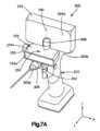
概して図2A~図2D、図7A~図7B、及び図13を参照すると、医療用撮像システム102は、外科用器具203に装着された計算装置204を含み得る外科用器具アセンブリ202を含み得る。外科用器具203は、解剖学的構造体124などの解剖学的構造に作用するように構成され得る。外科用器具203は本体205を画定することができ、計算装置204は、所望により本体205の任意の位置に取り付けられてもよい。一例では、図2A~図2Dを参照すると、計算装置204は、ひいてはディスプレイ212は、マウント228によって支持され得る。マウント228は支持表面230を含み得るが、この支持表面は、計算装置204を、ひいてはディスプレイ212を支持するものである。マウント228は、外科用器具203の支持表面230及び本体205に取り付けられたアーム232を更に含むことができ、それにより、ディスプレイ212は、外科用器具203の本体205に対して固定位置にある。アーム232又は支持表面230は、ディスプレイ212の視角を調整するために回転するように構成され得る。マウント228は、ディスプレイが外科用器具203の操作に干渉しないように配置され得る。計算装置204は、所望により、外科用器具205に代替的に取り付けられ得ることが理解されよう。2A-2D, 7A-7B, and 13, the
図7A、図7B、及び図8を参照すると、例えば、外科用器具アセンブリ202は、深さゲージ250を更に含み得る。深さゲージ250は、本明細書で更に説明するように、解剖学的構造に対して実行される穿孔操作の深さに関連するデータを測定し、決定し、かつ送信するように構成された1つ又は2つ以上のプロセッサを含み得る。いくつかの例では、深さゲージ250は、国際公開第2017/083992号に記載されている骨ねじの長さの決定に好適な測定装置に従って具現化され、この開示は、その全体が本明細書に記載されているかのように参照により組み込まれる。深さゲージ250は、代替的に具現化され得ることが理解されるであろう。深さゲージ250はディスプレイ212と通信することができる。深さゲージ250は、外科用器具203がドリルとして動作するときに外科用器具203の穿孔深さを測定するように構成され得る。深さゲージ250は、外科用器具203に対して固定位置で外科用器具203に固定され得る。深さゲージ250は、本体205に対して固定位置に固定されるように、外科用器具203の本体205に取り外し可能に取り付けられるか又は固定され得る。深さゲージ250は、本体205及び深さゲージ250に固定され得るアダプタ252によって支持され得る。アダプタ252は、外科用器具203が動作するときにアダプタ252、したがって深さゲージ250が本体250に対して固定位置に留まるように、本体205にクランプするために所望されるようにサイズ決めされ得る。一例では、アダプタ252は、例えば、アクチュエータ255を動かすことによって調整することができる。アクチュエータ255は、ノブなどとして構成され得る。例えば、アクチュエータ255を時計回り方向に回転させてアダプタ252を締め付けることができ、また、アクチュエータを反時計回り方向に回転させてアダプタ252を緩めることができる。7A, 7B, and 8, for example, the
深さゲージ250は、第1の端部又は前端部254aと、長手方向Lに沿って第1の端部254aの反対にある第2の端部又は後端部254bと、を画定する深さゲージ本体254を画定し得る。深さゲージ本体254は、第3の端部又は上端部254cと、長手方向Lに対して実質的に垂直な横断方向Tに沿って第3の端部254cの反対側にある第4の端部又は底端部254dと、を更に画定し得る。アダプタ252は、深さゲージ250の第4の端部254dに固定され得るが、深さゲージ250は、所望により、代替的にアダプタ252に固定され得ることが理解されるであろう。アダプタ252は、外科用器具203の本体205に圧入され得る。アダプタ252は、外科用器具203の本体205に固定されるクランプカラーを画定し得るが、アダプタ252は外科用器具203に代替的に固定され得ることが理解されるであろう。別の例では、深さゲージ250は、アダプタ252を使用せずに、外科用器具203に直接固定され得る。The
更に図7A、図7B、及び図8を参照すると、深さゲージ250は、深さゲージ本体254から、例えば、深さゲージ本体254の第2の端部254bにおいて延在する深さゲージ部材256を更に含み得る。計算装置204は、計算装置本体204a、及び深さゲージ部材256に取り付けられるように本体204aから延在する計算装置部材258を更に画定し得る。計算装置部材258は、計算装置部材258が計算装置本体204aに対して固定位置にあり得るように一体化され得る、又は他の方法で計算装置本体204aに取り付けられ得る。更に、ディスプレイ212は、計算装置本体204aに対して固定位置にあり得る。したがって、ディスプレイ212は、計算装置部材258に対して固定位置にあり得る。計算装置部材258は、深さゲージ部材256に対して回転するように構成され得る。一例では、計算装置部材は、横断方向Tと実質的に平行な軸線260を中心として回転するように構成される。したがって、ディスプレイ212は、横断方向Tと実質的に平行な軸線260を中心として回転するように構成され得る。例えば、ディスプレイ212は、操作が実施されている間にディスプレイ212の視角を調整するために、軸線260を中心として回転するように構成され得る。軸線260は、長手方向Lと横断方向Tの両方に対して実質的に垂直である横方向Aに沿って画定されるディスプレイ212の幅に対して中心に置かれ得る。ディスプレイ212は所望により代替の軸線を中心として回転するように構成され得ることが理解されるであろう。深さゲージ250の1つ又は2つ以上のプロセッサは、計算装置204に、したがってディスプレイ212に通信可能に結合され得る。一例では、深さゲージ250は、計算装置204にデータを無線で送信するように構成されている。例えば、深さゲージ250は、Wi-Fiネットワークを介して計算装置204にリアルタイムデータを提供することができる。7A, 7B, and 8, the
また、計算装置204は、代替的に外科用器具203と一体化され得ることも理解されよう。更に、外科用器具203は、例示を目的として外科用ドリルとして示されているが、計算装置204及び深さゲージ250は、多数の好適な代替的装置又は器具に装着され得るか、あるいはそれらと一体化され得ることが理解されよう。例えば、外科用器具アセンブリ202は、所望により、骨の領域若しくは解剖学的構造の他の部分を標的とし、医療用埋没物を取り除く、骨切り術若しくは任意の他の処置、例えば蛍光透視法を使用する任意の他の処置を実施するように構成された器具又は機器を含み得る。したがって、解剖学的構造124は骨として提示されているが、外科用器具アセンブリが動作するように構成され得る構造は、骨に限定されないことが理解されよう。It will also be appreciated that the
計算装置204は、したがって外科用器具アセンブリ202は、外科用器具に取り付けられ得るディスプレイ212を含み得る。ディスプレイ212は、撮像装置104によって生成された解剖学的構造124のX線透視画像を表示するように構成され得る。例示的な構成では、画像が撮像装置104によって生成されるのと同時に、解剖学的構造124の画像がディスプレイ212によって表示されるように、ディスプレイ212は解剖学的構造124のX線透視画像をリアルタイムで表示することができる。場合によっては、ディスプレイ212は、ひいては外科用器具アセンブリ202は、複数のディスプレイ、例えば、第1のディスプレイ212aと、第1のディスプレイ212aの配向と比較して異なる配向を有する第2のディスプレイ212bと、を含み得る。別の例示的な構成では、例えば図7A、図7B、図8、及び図13に示されるように、ディスプレイ212は、ひいては外科用器具アセンブリ202は、たった1つのディスプレイを含む。The
図2A~図2D、図7A~図7B、及び図13を参照すると、外科用器具203は、近位端部203b、及び近位端部203bの反対側にある作業端部203aを画定し得る。作業端部203aは、例えば、切断するか、穿孔するか、さもなければ標的、構造、例えば、内科患者の解剖学的構造124を操作するように構成され得る。ディスプレイ212は、近位端部203bに面し得る。ディスプレイ212、特に第1のディスプレイ212a及び第2のディスプレイ212bは、外科用器具203の近位の場所から作業端部203aとディスプレイ212の両方への視線をもたらすように配置され得る。したがって、場合によっては、例えば、医療専門家は、外科用器具203を操作している間に、外科用器具203のディスプレイ212と作業端部203aの両方を見ることができる。2A-2D, 7A-7B, and 13, the
一例では、外科用器具203は、外科用器具203の本体205に隣接する近位端部226bと、切断器具226の近位端部226bの反対側にある切断先端部226aとを含む、切断器具226を含む。切断先端部226aは、切断器具226の近位端部226bとは反対側にある切断器具の末端部を画定することができる。切断器具226は、解剖学的構造、例えば解剖学的構造124から解剖学的物質を取り除くように構成され得る切断先端部226aを有することができる。図示の例において、切断器具226はドリルビットであり、切断先端部226aはドリルビットの先端部であるが、切断器具226などの器具に加えてあるいはそれに代わって、他の器具及び構成が、本明細書で開示される実施形態を実装するために使用されてもよく、そのような全ての実施形態が、本開示の範囲内に含まれるものとして企図されることを理解されたい。In one example, the
外科用器具アセンブリ202は、外科用器具203の本体205に装着された、例えば軸線位置合わせツールなどの位置合わせツール218を含み得る。位置合わせツール218は、代替的に外科用器具203と一体化され得ることも理解されよう。位置合わせツール218は、外科用器具203の本体205に堅固に取り付けられ得る。一例では、切断器具226は外科用器具203の作業端部203aに位置し、位置合わせツール218は外科用器具の近位端部203bに位置するが、位置合わせツール218は、所望により代替的に位置し得ることが理解されよう。位置合わせツール218は、外科用器具203に近接する第1の表面218aと、第1表面218aの反対側にある第2の表面218bと、を画定することができる。第2の表面218bは平坦な表面を画定することができ、したがって位置合わせツール218は平坦な表面を画定することができる。したがって、位置合わせツール218の第2の表面218bは、平面を画定することができる。切断器具226(例えば、ドリルビット)は、位置合わせツール218の第2の表面218bによって画定される平面に対して垂直に配向され得る。一例では、位置合わせツール218は、位置合わせツールの第2の表面218bによって画定される平面に対して垂直に配向されるピンを含む。そのピンは、外科用器具203の近位端部203bによって画定された孔によって受容されるように構成され得る。外科用器具203の近位端部203bによって画定された孔は、切断器具226と平行な配向を有することができ、これにより、位置合わせツール218のピンが、位置合わせツール218の近位端部203bによって画定された孔によって受容されると、位置合わせツールの第2の表面218bは、切断器具226の配向に対して垂直な平面を画定する。The
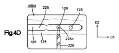
同様に図4A~図4Dを参照すると、解剖学的構造124のX線透視画像は、1つ又は2つ以上の標的部位126を含み得る。標的部位126は、外科用器具203が穿孔、切断、又は別様に標的とし得る解剖学的構造124上の部位を表し得る。図示の例によれば、標的部位126は、骨内の埋没物125、例えばIM釘又はロッドによって画定され得る。外科用器具アセンブリによって実施される例示的な手術は、開示される主題の説明を容易にするためにIM釘打ち手術として提示されているが、この例示的なIM手術は、本開示の範囲を限定することを意図したものではないことが理解されよう。したがって、外科用器具アセンブリ202は、例示的なIM釘打ち手術などの手術に加えて、あるいはその代わりに、他の手術を実施するために使用されてもよく、そのような全ての実施形態が本開示の範囲内で企図されることが理解されよう。4A-4D, the fluoroscopic image of the
ディスプレイ212は、とりわけ、IM釘打ち手術と関連するX線透視画像を表示することができる。ディスプレイ212は、遠位係止孔を穿孔すること、又は骨内にIM釘を配置することに関連する情報を表示することができる。更に、ディスプレイ212は、深さゲージ250と関連する画像又はデータを表示することができる。更に、ディスプレイ212は、ディスプレイ212がX線透視画像をレンダリングするのと同時に、深さゲージ250と関連する画像若しくはデータ並びに/又はIM釘打ち手術に関する情報を表示することができる。ディスプレイ212は、X線透視画像、例えば、医療用撮像装置104によって生成され、医療用撮像装置104から受信された、解剖学的構造124の例示的なX線透視画像400a~400dを表示するように構成され得る。特に図4Aを参照すると、ディスプレイ212、例えば第1のディスプレイ212aは、解剖学的構造124内の埋没物125の第1のX線画像400aを表示することができる。埋没物125は、解剖学的構造124から物質が取り除かれ得る1つ又は2つ以上の標的部位126を画定することができる。例示的なIM釘打ち手術では、画像装置104からのX線透視画像を表示するディスプレイ212を見ることによって、医療専門家は、図4Bに示すように、標的部位126が真円を画定するまで、患者とディスプレイ212とを同時に見ながら、患者又は撮像装置104を操作することができる。IM釘打ちの例では、1つ又は2つ以上の標的部位126が真円を画定するとき、ねじを係止するための孔を標的部位126において穿孔し得る。The
IM係止孔の状況において本明細書で使用されるとき、別段の指定がない限り、真円及び円は互換的に使用され得る。真円又は円は、幾何学的な円と比較して所定の閾値内にある係止孔の可視描画像を指し得る。該所定の閾値は、円によって表される位置に孔を穿孔するために必要な運用許容範囲によって定義され得る。一例では、係止孔の可視描画像は、その中心からその外周までの最小距離がその中心からその外周までの最大距離の少なくとも90%から最大で100%であるときに、真円を画定する。As used herein in the context of IM locking holes, perfect circle and circle may be used interchangeably unless otherwise specified. Perfect circle or circle may refer to a visual depiction of a locking hole that is within a predetermined threshold compared to a geometric circle. The predetermined threshold may be defined by the operational tolerance required to drill a hole at a location represented by the circle. In one example, a visual depiction of a locking hole defines a perfect circle when the minimum distance from its center to its circumference is at least 90% and at most 100% of the maximum distance from its center to its circumference.
再び図4Aを参照すると、例示的な実施形態において、遠位係止ねじの真円が、第1のX線画像400aに基づいて生成され得る。第1のX線画像400aは、医療用撮像装置104によって生成され得、またX線画像400aは、外科用器具アセンブリ202のプロセッサによって受信され得る。X線画像400aは、X線画像400aが埋没物125、例えばIM釘225の一部分を含むように、医療用撮像装置104が第1の位置にあるときに、医療用撮像装置104によって生成され得る。特に、IM釘225の該一部分は、第1の位置において医療用撮像装置104によって生成されたX線画像400aがIM釘225の該一部分を含むように、X線の進行方向128内にあり得る。4A again, in an exemplary embodiment, the true circle of the distal locking screw may be generated based on a
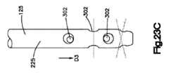
同様に図23A~図23Cを参照すると、IM釘225は、IM釘225を解剖学的構造124に固着又は固定するために、それぞれの係止ねじ304を受容するようにサイズ決めされた複数の係止孔302を画定し得る。第1のX線画像400aに示されるIM釘225の該一部分は、係止孔302の一部分、例えば、複数の係止孔302のうちの少なくとも2つの係止孔の一部分を含み得る。X線の進行方向128は、X線画像400aが取得される第1の方向又は視点を画定し得る。IM釘225は、第2の方向D2に沿った幅と、該第2の方向D2に実質的に垂直である第3の方向D3に沿った長さと、を画定し得る。第1のX線画像400aに映し出される係止孔302は、IM釘225の長さに沿って互いに離間され得る。医療用撮像装置104が第1のX線画像400aを生成する第1の位置にあるとき、X線の進行方向128は、少なくとも2つの係止孔302の一部分がX線画像400a上でそれぞれの楕円又はレンズ306として視認可能であるように、第2及び第3の方向D2及びD3の少なくとも1つ、例えば、両方と比較して、非直交であり得る。レンズは、それらの終端点で画定された2つの半円を画定し得ることが理解されよう。23A-23C, the
したがって、手術中、医療用撮像装置104は、IM釘225に対して第1の位置に配され得る。医療用撮像装置104が第1の位置にある間、医療用撮像装置104は、IM釘225の一部分を含む第1のX線画像400aを生成することができる。第1のX線画像400aに示されるIM釘225の該一部分は、IM釘225によって画定された係止孔の第1の視覚的視点を含み得、したがって第1のX線画像400aも該第1の視覚的視点を含み得る。例えば、第1の視覚的視点は、IM釘225によって画定された少なくとも2つの係止孔を含み得る。第1の視覚的視点は、X線画像400aに示される係止孔のそれぞれの外周に対応する楕円又はレンズを画定し得る。一例では、第1の視覚的視点は、X線画像400aに示される係止孔の対応する外周の各々の50%未満、例えば30%を含み得る。Thus, during surgery, the
図4Aを引き続き参照すると、外科用器具アセンブリ202のプロセッサは、IM釘の同一性を判定するために、複数のIM釘からIM釘225を識別することができる。一例では、図22を参照すると、ディスプレイ212は、釘オプション2202を含む可視指示、例えば、係止孔スクリーン2200を提供するように構成され得る。ユーザは、対応する釘オプション2202を作動させることによって、所与の手術で使用されるIM釘を選択することができ、これにより、プロセッサが、選択された釘オプション2202と関連付けられたIM釘同一性を判定することができる。したがって、場合によっては、プロセッサは、ユーザインターフェース216を介したユーザ選択に応じてIM釘225の同一性を判定することができる。例えば、ディスプレイ212は、所与のIM手術に利用可能な複数のIM釘の視覚画像又は説明テキストを含み得る、釘オプション2202を表示することができる。ユーザ、例えば医療専門家は、適切なIM釘オプション2202を、例えばタッチなどによって作動させることができる。代替的に、プロセッサは、第1のX線画像400aからIM釘225の画像を認識することによってIM釘225を識別するように構成され得る。IM釘の同一性に基づいて、プロセッサは、係止孔の位置及びサイズを含み得る、その物理的特性又は特徴など、IM釘225と関連付けられる情報を取得することができる。4A, the processor of the
IM釘225に関する取得された情報に基づいて、したがってIM釘の同一性に基づいて、プロセッサは、第1のX線画像400a上で可視である係止孔304を識別することができる。例として、IM釘が5つの係止孔を含む場合、プロセッサは、識別されたIM釘225の物理的特性に基づいて、5つの係止孔のうちのどの2つがX線画像400a上に映し出されるかを識別することができる。更なる例として、プロセッサは、特定の係止孔がIM釘の終端部から離れている距離をX線画像400aから識別してもよく、また、所与の係止孔を識別するために、取得され得るIM釘の物理的特性と該距離を比較することができる。代替的に、図22を再び参照すると、係止孔スクリーン2200は、孔オプション2204を含み得る。場合によっては、IM釘が識別された後、識別されたIM釘によって画定された孔に対応する孔オプション2204が表示される。ユーザは、所与の穿孔操作の対象である係止孔を選択することができ、あるいはユーザは、X線画像400aで可視である1つ又は2つ以上の係止孔を選択することができる。したがって、場合によっては、プロセッサは、ユーザインターフェース216を介したユーザ選択に応答して穿孔される標的部位126を画定する係止孔302を決定することができる。例えば、ディスプレイ212は、特定のIM釘によって画定された複数の係止孔の視覚画像又は説明テキストを含み得る、係止孔オプション2204を表示することができる。ユーザ、例えば医療専門家は、例えば、タッチなどによって適切な係止孔オプション2202を作動させることができ、それによって医療用撮像装置104は、適切な係止孔を円として示す適切な係止孔の画像を生成するように、その位置の調整を行うことができる。Based on the acquired information regarding the
したがって、第1のX線画像400aに示される少なくとも2つの係止孔302の一部分に基づいて、またIM釘の同一性に基づいて、外科用器具アセンブリのプロセッサは、医療用撮像装置104の第1の位置とは異なる第2の位置を決定することができる。別の言い方をすれば、X線画像400aに示される係止孔の視覚的視点に基づいて、IM釘225に対する医療用撮像装置104の第2の位置が決定され得る。特に、第2の位置にある医療用撮像装置104によって画定されるX線の進行方向128は、第1の位置にある医療用撮像装置104によって画定されるX線の進行128とは異なり得る。図4Bを参照すると、医療用撮像装置104が第2の位置に配置され、第2の位置から第2のX線画像400bを生成するとき、又は医療用撮像装置104が第2の位置にある間、第2のX線画像400bは、対応する円308として示される係止孔302を含み得る。したがって、第2のX線画像400bは、第1のX線画像400aに示される係止孔の第2の視覚的視点を含み得、第2の視覚的視点は、係止孔の外周に対応する円を画定し得る。場合によっては、第2のX線画像400bは、第1のX線画像400aに示される少なくとも2つの係止孔の第2の視覚的視点を含み得、第2の視覚的視点は、少なくとも2つの係止孔の外周に対応する円を画定し得る。Thus, based on a portion of at least two locking
X線の進行方向128は、医療用撮像装置104が第2の位置にあるときに、IM釘225の長さに対して実質的に垂直又は直交をなし得る。X線の進行方向128は、少なくとも2つの係止孔302が第2のX線画像400b上でそれぞれの円に見えるように、医療用撮像装置104が第2の位置にあるときに、第2及び第3の方向D2及びD3に対して実質的に垂直をなし得る。したがって、医療用撮像装置104は、係止孔の第2の視覚的視点(例えば、X線画像400b)の円の外周によって画定される平面に対して実質的に垂直であるX線の進行方向128が医療用撮像装置によって画定されるように、第2の位置に配され得る。The
場合によっては、第1のX線画像400aに示されるIM釘225の一部分は、2つの係止孔のみの可視部分を含む。更に、X線画像に示される2つの係止孔の一部分は、2つの係止孔302の30%未満、例えば、2つの係止孔302の表面積の30%未満など、50%未満であり得る。したがって、例示的な操作として、医療専門家は、2つの係止孔の一部分のみを含むIM釘の1つのX線画像を取得することによって、係止孔を穿孔する向きを識別することができ、2つの係止孔の該一部分は、1つのX線画像上でそれぞれの楕円又はレンズとして視認可能であり得る。したがって、2つの係止孔の視覚的視点及びIM釘の物理的特徴のみに基づいて、医療用撮像装置の第2の位置が、2つの係止孔を真円として表すために決定され得る。更に、IM釘の物理的特徴及び第1のX線画像400aのみに基づいて、複数の係止孔302、例えば、(X線画像400aに映し出される係止孔だけでなく)IM釘の全ての係止孔を穿孔するための配向が決定され得る。その結果、場合によっては、医療用撮像装置104は、第1のX線画像400a及びIM釘の同一性のみに基づいて、特定のIM釘の全ての係止孔302を表示するように調整され得る。真円の位置は、例えば、2017年6月27日に発行された米国特許第9,687,308号に記載されている任意の好適な方法を使用して、楕円の画像に基づいて決定され得る。この特許の開示は、参照により全体が本明細書に組み込まれる。In some cases, the portion of the
したがって、図4Aを参照すると、外科用器具アセンブリ202のプロセッサは、医療用撮像装置104が第3の位置に配置され、第3の位置からX線画像、例えば第3のX線画像を生成するときに、該生成されたX線画像が、円として示されるIM釘の所与の係止孔、例えば第3の係止孔302aを含むように、医療用撮像装置104の第3の位置を決定することができ、第3の係止孔302aは、第1のX線画像400aに示された(楕円又はレンズとして示される)係止孔302のうちのいずれの係止孔とも異なり、これに基づいて、第3の位置が決定される。特に、第1のX線画像400aに示される少なくとも2つの係止孔302の視覚的視点に基づいて、かつIM釘225の物理的特徴に基づいて、該少なくとも2つの係止孔のうちの1つではない所与の係止孔(例えば、係止孔302a)を真円として表すための医療用撮像装置104の位置が決定され得る。実施例について続けると、医療用撮像装置104が第3の位置にある間、医療用撮像装置104は、IM釘225の第3の係止孔302aの視点を含む第3のX線画像を生成することができ、係止孔302aの少なくとも外周、例えば係止孔302a全体は、第1のX線画像400aにおいて可視ではない。第3の位置から生成される係止孔302aの視点は、係止孔302aの外周に対応する円を画定し得る。4A, the processor of the
外科用器具アセンブリ202のプロセッサは、IM釘の同一性に基づいて、メモリから所与のIM釘の物理的特徴を取り出すことができる。いくつかの例では、医療用撮像装置104は、ユーザが孔オプション2204上の特定の係止孔を選択したことに応答して、円として示される特定の係止孔のX線画像を生成するように位置を自動的に変更する。The processor of the
再び図22を参照すると、プロセッサは、医療用撮像装置104の第1の位置及び第2の位置に基づいて調整座標2206を決定することができる。ディスプレイ212、例えば、ロック画面2200は、調整座標2206を表示することができる。医療用撮像装置104は、調整座標2206に従って、その位置を調整するために、特にX線の進行方向128を調整するために、その運動センサ269からのデータに依存し得る。代替的に、あるいは追加的に、医療専門家は、調整座標2206に従って、患者と、特にIM釘225が、第1のX線画像400aが生成されたときと同じ位置に留まっている間、医療用撮像装置104を移動させることができる。調整座標2206は、X線の進行方向128が、第1の位置から第2の位置又は第3の位置に到達するようにどのように調整されるかを示し得る。例として、調整座標2206は、X線の進行方向128(したがって、医療用撮像装置104の方向)がどのようにして第1の平面に沿って調整されるかを示す第1の座標2208と、X線の進行方向128(したがって、医療用撮像装置104の方向)がどのようにして、第1の平面に対して実質的に垂直である第2の平面に沿って調整されるかを示す第2の座標2210と、を含み得る。図示のように、第1の座標2208及び第2の座標及び2210は、第1のX線画像400aが生成されたときのそれらの位置に対する度で示されているが、実施形態が度に限定されないことが理解されるであろう。例えば、運動センサ269は、X線トランスミッタ106及びX線レシーバ108の実際の位置に対応する位置座標を検出することができ、またディスプレイ212は該位置座標を表示することができる。位置座標は、X線トランスミッタ106及びX線レシーバ108の位置が変化するときに、例えば、外科用器具アセンブリ202のプロセッサによって、医療用撮像装置104から受信され得るが、その結果、表示される位置座標は、X線トランスミッタ106及びX線レシーバ108が移動するときに変化する。22, the processor can determine an adjustment coordinate 2206 based on the first and second positions of the
引き続き図22を参照すると、ディスプレイ212は、外科用器具アセンブリ202のプロセッサが医療用撮像装置104から第1のX線画像400aを受信したことに応答して、医療用撮像装置104の第2の位置及び/又は第3の位置を示すように構成され得る。指示は調整座標2206を含んでもよく、あるいは該指示は、所望により、可聴コマンド又は代替的なグラフィック指示を含んでもよく、それによって、ユーザは、係止孔を真円として示す画像を生成するために、医療用撮像装置104を第1の位置から別の位置、例えば第2又は第3の位置に調整することができることが理解されるであろう。例示的な手術では、医療用撮像装置104が、所与の係止孔が真円として表示される第2の位置にあるとき、第2の位置にある医療用撮像装置104によって画定されるX線の進行方向128に沿って所与の係止孔のための孔が穿孔される。22, the
ここで図4Cを参照すると、ディスプレイ212は、例示的なX線透視画像400cを表示することができる。したがって、ディスプレイ212は、解剖学的構造124のX線透視画像上の標的部位126に対する、切断器具226の切断先端部226aの位置を表示するように構成され得る。X線透視画像400cは、例えば、図6Bに示される切断先端部226aの位置を示すことができる。切断先端部226aは、解剖学的構造124の1つ又は2つ以上の標的部位126から解剖学的物質を取り除くように構成され得る。更に、図4Dに示されるように、切断器具226(例えばドリルビット)の先端部226aは、例えば標的部位126の中心で解剖学的構造124上に配置され得る。ディスプレイ212は、外科用器具203の近位の場所から先端部226a及びディスプレイ212の両方への視線を提供するように配置されてもよく、それにより、医療専門家は、先端部226aを標的部位126で中心に置くために、X線透視画像400cと400dの両方を、ひいては先端部226a、及び解剖学的構造124を見ることができる。外科用器具203のディスプレイ212は、医療用撮像装置104のディスプレイ112をミラーリングすることができ、それにより、外科用器具アセンブリ202のディスプレイ212は、撮像装置104のディスプレイ112がレンダリングするのと同じ画像を同時にレンダリングして、画像をリアルタイムで表示することができる。4C, the
場合によっては、例えば、ユーザインターフェース216を介したユーザ選択に基づいて、外科用器具アセンブリ202は、ディスプレイ212における垂直又は水平方向が、解剖学的構造124に対する外科用器具203の移動のそれぞれ垂直又は水平方向に対応するような回転配向へと、ディスプレイ212に表示されるX線透視画像を回転することができる。したがって、場合によっては、ディスプレイ212によって表示される回転配向のX線透視画像は、外科用器具203に結合されるディスプレイ212とは別個の医療用撮像装置ディスプレイ112上に表示されるX線透視画像と比較して、回転され得る。In some cases, for example, based on a user selection via the
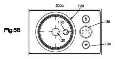
ここで図5A~図5Cを参照すると、ディスプレイ212はまた、可視指示、例えば、X線トランスミッタ106からX線レシーバ108へのX線の進行方向128に対する切断先端部226aの位置合わせの配向画像129を提供するように構成され得る。一例では、ディスプレイ212は、第1のディスプレイ212aと、第2のディスプレイ212bとを含み、第1のディスプレイ212aは、撮像装置104からX線透視画像(例えば、X線透視画像400a~400c)を表示するように構成され、第2のディスプレイ212bは、切断器具226の配向の可視指示を含んだ配向画面(例えば、配向画面500a~500c)を表示するように構成される。第1のディスプレイ212aが同様にあるいは代替的に、配向画面を表示してもよく、また、第2のディスプレイ212bが同様にあるいは代替的に、X線透視画像を表示してもよいことが理解されよう。更に、ディスプレイ212は、場合によっては、X線透視画像及び配向画面の両方を同時に表示し得るたった1つのディスプレイを含み得る。更に、図11及び図12を参照すると、ディスプレイ212は、場合によっては、X線透視画像、配向画面、及び深さゲージデータの任意の組み合わせを同時に表示することができるたった1つのディスプレイを含み得る。一例では、ユーザは、ユーザインターフェース216を介してオプションを選択して、ディスプレイ212によって表示されるX線透視画像、配向画面、又は深さゲージデータを選択することができる。別の例では、ディスプレイ212は、X線透視画像、配向画面、及び深さゲージデータの任意の組み合わせがディスプレイ212によって同時に表示され得るように、分割、例えば半分に分割、又は3つに分割されてもよい。本明細書に記載される、ディスプレイ212によって表示され得る画像(例えば、図4A~図4C、図5A~図5C、図10A~図22)は、網羅的ではないことが理解されるであろう。ディスプレイ212は、様々な構成又は代替的な可視描画像を介して、様々な情報をユーザに提供することができる。5A-5C, the
位置合わせの可視指示、例えば配向画像129は、X線の進行方向128に基づくものであってもよく、また切断器具226の配向に対応する加速度計情報に更に基づくものであってもよい。例えば、外科用器具アセンブリ202の加速度計215は、医療用撮像装置104のX線発生器106からX線レシーバ108へのX線の進行方向128を用いて較正され得る。例示的な較正において、外科用器具203に取り付けられた位置合わせツール218は、切断器具226(例えばドリルビット)をX線の進行方向128と位置合わせするために、所定の配向を有する医療用撮像装置104の表面と見当合わせされるように構成される。一例では、位置合わせツール218は、X線トランスミッタの平坦な表面106aと見当合わせされるように構成されるが、位置合わせツール218は、必要に応じて医療用撮像装置104の他の表面と見当合わせされるように構成され得ることが理解されよう。特に、位置合わせツール218の第2の表面218bは、切断器具226がX線の進行方向128と位置合わせされたときに、医療用撮像装置104の平坦な表面106aに当接し得る平坦な表面であり得る。引き続きこの例について言えば、医療用撮像装置104によって、具体的には医療用撮像装置104によって生成されるX線ビームの方向を用いて加速度計215を較正するために、位置合わせツール218の表面218bがX線発生器106の平坦な表面106aに当接するときに、ゼロ値が設定され得る。一例では、ゼロ値を設定し、それにより、X線の進行方向128を用いて加速度計215を較正するために、切断器具226がX線の進行方向128に沿って配向されたときにゼロ値が設定されるように、位置合わせツールの表面218bがX線発生器106の平坦な表面106aに対して平坦であるときに、ユーザがディスプレイ212上で較正オプション134を作動させることができる。The visual indication of alignment, e.g.,
別の例において、較正器具は、医療用撮像装置104の一部であってもよいか、又はそれに取り付けられてもよい。医療用撮像装置104、特にX線の進行方向128が、ある操作を実施するために所望の位置に配向されているとき、医療用撮像装置104の較正器具は、ゼロ値が所望のX線の進行方向128に対応するように、重力に対するゼロ値を識別することができる。医療用撮像装置104の較正器具は、重力に対するゼロ値を加速度計215に送ることができる。したがって、外科用器具アセンブリ202は、医療用撮像装置104によって画定されるX線の進行方向128を用いて、外科用器具アセンブリ202の加速度計215を較正するように、医療用撮像装置104のX線発生器106からX線レシーバ108へのX線の進行方向128を表すゼロ値を医療用撮像装置104から受信することができる。加速度計215は、重力に対するゼロ値を、医療用撮像装置104の較正器具から受信するゼロ値に設定することができ、それにより、加速度計215はX線の進行方向128を用いて較正される。したがって、加速度計215は、切断器具226がX線の進行方向128に沿って配向されたときにゼロ値を示すことができる。In another example, the calibration tool may be part of or attached to the
一例では、加速度計215はディスプレイ212の配向に対応する。したがって、場合によっては、切断器具226に対するディスプレイ212の配向が調整されると、ゼロ値は、X線の進行方向128を用いて加速度計215を再較正するように再設定される。いくつかの例では、ディスプレイ212は、切断器具226に対して1つ又は2つ以上の事前設定された配向(例えば、90度、75度など)を有する。したがって、場合によっては、第1の事前設定された配向における較正後、ディスプレイ212は、第2の事前設定された配向へと移動され得る。一例では、ユーザは、ユーザインターフェース216を使用して、ディスプレイ212が配置される事前設定された配向を選択することができる。加速度計215は、第2の事前設定された配向を受信し、それに応じてゼロ値を調整することができ、それにより、加速度計が再較正されることなくディスプレイ212が調整される。更に別の例では、医療用撮像装置104は、X線の進行方向の配向の変化を識別し得る加速度計を含む。この例では、医療用撮像装置の加速度計は、X線の進行方向の配向の変化を外科用器具アセンブリ202に送信することができ、それにより、加速度計215を再較正することなくゼロ値が再設定され得る。したがって、ゼロ値は、X線発生器106及びX線レシーバ108の配向の変化に従って調整され得る。In one example, the
例えば、外科用器具アセンブリ202の加速度計215がX線の進行方向を用いて較正されるとき、加速度計は、X線の進行方向128に対する切断器具226の配向を示す加速度計情報を生成することができる。加速度計情報は、ディスプレイ212によって、様々な配向画面、例えば、配向画像129を含み得る配向画面500a~500cに表示され得る。IM釘打ちの例として、外科用器具アセンブリ202を使用しながら配向画像129を見ることによって、切断器具226は穿孔中も適切な配向に維持され得る。すなわち、真円を画定する孔が標的部位126に穿孔され得る。For example, when the
例えば、図5A~図5Cを参照すると、配向画面500a~500cは、静止領域130と可動インジケータ132とを含み得る配向画像129を含むことができる。可動インジケータ132は、切断器具226の配向の典型であり得る。一例では、可動インジケータ132が静止領域130に対する所定の空間的関係を有するとき、切断器具226はX線の進行方向128に配向される。一例では、切断器具226の先端部226a(例えばドリルビット)が標的部位126と位置合わせされ、可動インジケータ132が静止領域130に対する所定の空間的関係を有している間に、孔が解剖学的構造124に穿孔される。所定の空間的関係は、所望により異なり得ることが理解されよう。いくつかの例では、可動インジケータ132が静止領域130の上に重なるとき、切断器具226はX線の進行方向128に配向される。いくつかの例では、図5Cに示すように、可動インジケータ132が静止領域130によって画定される境界内にあるとき、切断器具226はX線の進行方向128に配向される。For example, referring to FIGS. 5A-5C, the orientation screens 500a-500c can include an
図4A~図4Dを参照して上述されたように、ディスプレイ212は、IM釘を固定するために係止ねじを配置することに関連するX線透視画像及びユーザインターフェースを表示することができる。ここで図13~20を参照するが、ディスプレイ212は、追加的にあるいは代替的に、X線画像又はX線透視画像、並びに、埋没物125、例えばIM釘を配置することと関連するユーザインターフェースを表示することができる。ディスプレイ212は、X線画像、例えば、X線データ又は画像602(図13、図14A、図14B)、X線画像604(図15)、X線画像606(図16)、X線画像608(図17)、X線画像610(図18)、並びにX線画像630a及び630b(図20)を表示するように構成され得る。本明細書で使用されるとき、特に断らない限り、X線データとX線画像は、限定することなく、互換的に使用され得る。特に図14Aを参照すると、ディスプレイ212は、解剖学的構造124のX線データ602を表示することができる。図示の例によれば、X線データ602は、埋没物125用に解剖学的構造224に孔を穿孔するように位置付けられた切断器具226を含む。X線データ602は、穿孔操作のために軟組織を移動させるように位置付けられたクランプ612を更に含む。一例では、解剖学的構造又は骨124のIM管に会合するように孔が穿孔され得る。したがって、孔は、骨への進入点と、進入点とIM管との間の軌道と、を画定することができ、埋没物125(例えば、IM釘又はロッド)は、埋没物125を受容するようにサイズ決めされた孔に挿入され得る。本明細書では、穿孔操作の適切な軌道及び進入点(例えば、痛みを最小限にするため)は、骨及び/又は挿入される埋没物のタイプに応じて異なり得ることが認識される。本明細書では、適切な軌道及び進入点が所与の手術室内で容易にはアクセス可能でない場合もあり、したがって、所与の医療専門家は個人的な知識に依存して、適切な軌道及び進入点を推定する場合もあることが、本明細書において更に認識される。更に、適切な軌道及び入口点が既知である場合であっても、穿孔操作は通常はフリーハンドで実施されるものであり、したがって、実際の軌道及び進入点は適切な軌道及び進入点とは異なり得る。As described above with reference to FIGS. 4A-4D, the
例示的な実施形態では、図14B及び図17を参照すると、外科用器具アセンブリ202のプロセッサは、解剖学的構造124の境界614、例えば第1の境界若しくは前後方向(AP)の境界615(図14B及び図15)又は第2の境界若しくは横方向の境界617(図16及び図17)を識別又は判定し得る。境界614は、解剖学的構造124の第1の最外縁部614aと、第1の最外縁部614aの反対側の解剖学的構造124の第2の最外縁部614bと、を画定し得る。いくつかの例では、プロセッサは、その開示は、その全体が本明細書に記載されるように参照により組み込まれる米国特許出願公開第2007/0274584号に記載されている縁部検出プロセスを実施することによって境界614を判定することができる。他の縁部検出アルゴリズムが所望に応じて実施されてもよく、上述の縁部検出プロセスは、例示を目的として提示されたものであることが理解されるであろう。場合によっては、プロセッサは、ユーザインターフェース216を介したユーザ選択に基づいて境界614を識別することができる。例えば、ディスプレイ212は、手動位置合わせオプション646などのオプションを表示することができる。ユーザ、例えば医療専門家は、手動位置合わせオプション646を、例えばタッチなどによって作動させることができる。手動位置合わせオプション646が作動されると、ユーザは、X線データ上に1つ又は2つ以上の画像を手動でオーバーレイすることができ、それにより、ディスプレイ212はX線データ上に1つ又は2つ以上の画像を表示する。ユーザが手動でオーバーレイし得る画像の例は、境界614である。例として、ユーザは、スタイラス、指などを使用して、X線データ上に画像を手動でオーバーレイすることができる。一例では、ユーザは、外科用器具アセンブリ202のプロセッサによって判定される境界614を調整するために、手動位置合わせオプション646を作動させることができる。例えば、プロセッサは、境界614を判定するために縁部検出プロセスを実施することができるが、場合によっては、縁部検出プロセスは、解剖学的構造124の実際の最外縁部からオフセットする境界614の部分を得ることになり得る。例えば、縁部検出プロセスは、解剖学的構造124内の骨折を境界614の一部分として誤って識別することがある。この例では、ユーザは、ユーザインターフェース216を介して、解剖学的構造124の最外縁部を表現するものとして誤って識別される境界614の部分を調整することができる。したがって、外科用器具アセンブリ202は、ユーザがユーザインターフェース216のオプションのうちの少なくとも1つを作動させていることに応答して、境界614の少なくとも一部分、例えば全てを調整することができる。In an exemplary embodiment, referring to FIGS. 14B and 17, the processor of the
図14B、図15、図16、及び図17に示されるように、ディスプレイ212は、解剖学的構造124の境界614を表示するために、解剖学的構造124のX線画像上に境界614をオーバーレイすることができる。図18及び図20を参照すると、外科用器具アセンブリ202のプロセッサは、解剖学的構造124の軸線616を判定することができる。外科用器具アセンブリ202のプロセッサは、解剖学的構造への進入点620を画定する軌道618の表現を決定することができる。図14B~図18及び図20を参照すると、ディスプレイ212は、軌道の表現618を表示するために、解剖学的構造124のX線画像上に軌道618の表現をオーバーレイすることができる。軌道618の表現は、解剖学的構造124のIM管と会合するように孔が穿孔され得る線を画定し得る。軌道618の表現は、軸線616に基づいて決定され得る。更に、図18及び図20を参照すると、ディスプレイ212は、解剖学的構造124の軸線616を表示するために、解剖学的構造のX線画像上に境界616をオーバーレイすることができる。As shown in Figures 14B, 15, 16, and 17, the
いくつかの例では、軸線616は、解剖学的構造の長さに沿って中心線を画定し得る。図14B~図17を参照すると、軌道は、軌道618の表現と軸線616とが互いに重なり合い得るように、軸線616と一致し得る。例えば、第1の最外縁部614aは、解剖学的構造の長さに対して実質的に垂直な解剖学的構造の幅を画定するように、第2の最外縁部614bから離間され得る。したがって、軸線616は、解剖学的構造体124の長さに沿って、第1の最外縁部614aと第2の最外縁部614bから等距離にあってもよい。場合によっては、プロセッサは、ユーザインターフェース216を介したユーザ選択に基づいて軸線616を識別することができる。例として、ユーザ、例えば医療専門家は、手動位置合わせオプション646を、例えばタッチなどによって作動させることができる。手動位置合わせオプション646が作動されると、ユーザは、X線データ上に1つ又は2つ以上の画像を手動でオーバーレイすることができ、それにより、ディスプレイ212はX線データ上に1つ又は2つ以上の画像を表示する。ユーザが手動でオーバーレイし得る画像の例は、軸線616である。図示のように、軸線616は破線として表現されているが、軸線616は、例えば実線によって、所望に応じて代替的に表現され得ることが理解されるであろう。例として、ユーザは、スタイラス、指などを使用して、X線データ上に画像を手動でオーバーレイすることができる。一例では、ユーザは、境界614、具体的には第1の最外縁部614a及び第2の最外縁614bに基づいて、外科用器具アセンブリ202のプロセッサによって決定される軸線616を調整するために、手動位置合わせオプション646を作動させることができる。したがって、外科用器具アセンブリ202は、ユーザがユーザインターフェース216のオプションのうちの少なくとも1つを作動させたことに応答して、軸線616の少なくとも一部分、例えば全てを調整又は決定することができる。更に、外科用器具アセンブリ202は、解剖学的構造体124の境界614に基づいて解剖学的構造124の軸線616を決定することができ、そのため、解剖学的構造体の境界614が変化する場合、解剖学的構造124の軸線616は境界線614への変化に従って変化する。例えば、第2の最外縁部614bは、第1の最外縁部614aから離れるように調整され、外科用器具アセンブリ202は、境界614が調整される前に軸線616が表示される場合と比較して、軸線616が第1の最外縁部614aから更に離れて表示され得るように、軸線616を第2の最外縁部614bに向かって移動させることができる。In some examples, the
理論に束縛されるものではないが、本明細書に記載される実施形態は、手術室で撮影されるX線画像の数を減少させることができ、それによって所与の操作を実施するのにかかる時間を短縮することができることが認識される。一例では、図14A~図15及び図20のX線画像630aを参照すると、ディスプレイ212は、第1の視野又は前後方向(AP)の視野からの解剖学的構造124のX線画像を表示することができる。外科用器具アセンブリは、解剖学的構造124への進入点620を画定する軌道618の表現を決定し得る。ディスプレイ212は、軌道618の表現を表示するために、解剖学的構造124のX線画像上に軌道618の表現をオーバーレイすることができる。Without being bound by theory, it is recognized that the embodiments described herein may reduce the number of x-ray images taken in an operating room, thereby reducing the time it takes to perform a given procedure. In one example, referring to x-ray image 630a in FIGS. 14A-15 and 20, the
場合によっては、プロセッサは、ユーザインターフェース216を介したユーザ選択に応じて軌道618の表現を決定することができる。例えば、ディスプレイ212は、自動位置合わせオプション622などのオプションを表示することができる。ユーザ、例えば医療専門家は、自動位置合わせオプション622を、例えばタッチなどによって作動させることができる。自動位置合わせオプション622が作動されると、外科用器具アセンブリ202のプロセッサは、解剖学的構造124への進入点620を画定する軌道618の表現を決定することができる。外科用器具アセンブリはまた、自動位置合わせオプション622が選択又は作動されたことに応じて、軸線616若しくは境界614、又は軸線616と境界614との両方を決定することができる。更に、自動位置合わせオプション622が作動されたことに応じて、ディスプレイ212は、軌道618の表現、軸線616、及び/又は境界614を表示するために、解剖学的構造124のX線画像上に、軌道618の表現、軸線616、及び境界614のうちの少なくとも1つ、例えばそれらのうちの1つのみ、例えばそれらの任意の組み合わせをオーバーレイすることができる。In some cases, the processor can determine a representation of the
いくつかの例では、外科用器具アセンブリ202は、技術情報、例えば、メモリ214に記憶された技術情報に基づいて軌道618の表現を決定することができる。このような技術情報は、IM釘を配置するために、様々な骨に孔を穿孔するのに適切な軌道を含み得る。この技術情報に基づいて、外科用器具アセンブリ202は、軌道の表現を決定することができる。例として、技術情報は、APの視野から見た所与の骨に対する軌道が、小転子のすぐ下の点から測定される軸線から5度の横方向であることを明記したものであってもよい。引き続きこの例に関して言えば、技術情報は、横方向の視点からの所与の骨に対する軌道が、大転子の中心にあり、髄管と一直線をなすことを明記したものであってもよい。一例では、骨及び釘のタイプがユーザインターフェース216を介してプロセッサに入力されてもよく、またX線画像に対応する視野(例えば、横方向又はAP)がユーザインターフェース216を介してプロセッサに入力されてもよい。これに応答して、プロセッサは、X線画像の視野、骨のタイプ、及び釘に対応する技術情報を取得することができる。取得された技術情報に基づいて、軌道が決定され得る。場合によっては、プロセッサは、境界614を最初に決定し、次いで境界に基づいて軸線616を決定する。軌道618の表現は、軸線616及び技法情報に基づいて決定され得る。例えば、技術情報は、軌道が第1の視野においては軸線616と一致し、第1の視野に対して実質的に垂直な第2の視野においては特定の角度だけ軸線から角度的にオフセットしている(図19を参照)ことを示すものであってもよい。In some examples, the
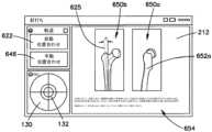
図19を参照すると、所与のユーザは、ユーザインターフェース216を介してユーザ選択を作動させる外科用器具アセンブリから技術情報を取得することができる。例えば、ユーザ選択により、ディスプレイ212に技術情報650a及び650bを表示させることができる。技術情報650aは、APの視野からの適切な軌道652aのグラフィック描写を含み得る。技術情報650bは、横方向の視野からの適切な軌道652bのグラフィック描写を含み得る。表示され得る技術情報は、いくつかの操作の中でも特に、IM釘を配置するための、テキストで指示654を含み得る。一例では、ユーザ選択に応じて、ユーザインターフェース216は、とりわけ、IM釘打ち操作と関連付けられた可聴指示をレンダリングすることができる。19, a given user may obtain technical information from the surgical instrument assembly actuating a user selection via the
場合によっては、所与のユーザ、例えば医療専門家が、外科用器具アセンブリ202によってレンダリングされた技術情報を利用して、所与のX線画像上に軌道618の表現を手動でオーバーレイすることができる。例えば、ユーザは、手動位置合わせオプション646を、例えばタッチなどによって作動させることができる。手動位置合わせオプション646が作動されると、ユーザは、ディスプレイ212がX線データ上に軌道618を表示するように、軌道618の表現を手動でオーバーレイすることができる。軌道618の表現は、実線、破線などを画定することができる。一例では、ユーザは、自動位置合わせオプション622が選択された後に外科用器具アセンブリ202のプロセッサによって判定される境界616を調整するために、手動位置合わせオプション646を作動させることができる。外科用器具アセンブリ202は、ユーザがユーザインターフェース216のオプションのうちの少なくとも1つを作動させていることに応答して、軌道の表現の少なくとも一部分、例えば全てを調整又は決定することができる。したがって、外科用器具アセンブリ202のプロセッサは、軌道の新しい表現を画定するように軌道の表現を調整することができ、ディスプレイ212は、新しい軌道の新しい表現を表示するために、解剖学的構造のX線画像上に新しい軌道の新しい表現をオーバーレイすることができる。一例では、プロセッサは、ユーザがユーザインターフェース216のオプションのうちの少なくとも1つを作動させていることに応答して、軌道の表現を調整することができる。In some cases, a given user, e.g., a medical professional, may utilize technical information rendered by the
図14Bを参照すると、X線画像602上で見ることができる軌道618及び切断器具226の表現を見ることによって、ユーザは、図15のX線画像604に示されるように、切断器具226を移動させて軌道の表現と位置合わせされ得る。代替的に、自動化されたシナリオでは、切断器具226は、軌道618の表現と位置合わせされるように自動的に移動され得る。一例では、切断器具226が軌道618の表現と位置合わせされると、医療用撮像装置104は、X線画像606及び608を生成するために、X線画像602及び604を生成したX線移動の方向とは異なる、X線トランスミッタ106からX線レシーバ108へのX線移動128の新たな方向を画定するように調整され得る。例えば、医療用撮像装置104は、図14B及び図15に示される第1の視野又はAPの視野に対してほぼ垂直な第2の視野又は横方向の視野を生成するように調整され得る。14B, by viewing the representation of the
図14B、図15、及び図20を参照すると、軌道618の表現は、第1の視点からの、例えばAPの視点からの軌道の第1の表現618aと称され得る。一例では、図16、図17及び図20を参照すると、外科用器具アセンブリ202は、解剖学的構造124への進入点620を画定する軌道の第2の表現618bを決定することができる。第2の表現618bは、第2の視点からのものであってもよい。例として、第2の視点は、第1の視点がAPの視野を画定し得、第2の視点が横方向の視野を画定し得るように、第1の視点に対してほぼ眼窩周囲にあってもよい。軌道の第2の表現618bは、軌道618の表現を決定及び表示するための、本明細書に記載された実施形態のいずれかに従って、決定及び表示され得る。14B, 15, and 20, the representation of the
図14B~図18を参照すると、ディスプレイ212は、解剖学的構造の進入点620に対する切断先端部226aの位置を表示することができる。軌道の第2の表現618bと、X線画像606及び608上で見ることができる切断器具226と、を見ることによって、ユーザは、切断器具226を、したがって切断先端部226aを移動させて、軌道の第2の表現618bと位置合わせすることができる。代替的に、自動化されたシナリオでは、切断器具226は、軌道の第2の表現618bと位置合わせされるように自動的に移動され得る。With reference to FIGS. 14B-18, the
場合によっては、切断器具226が、したがって切断先端部226aが軌道の第1の表現618a及び軌道の第2の表現618bと位置合わせされると、本明細書に記載の技術情報から決定され得る適切な進入点及び軌道に、切断器具226が位置合わせされたときに、穿孔操作が開始され得る。ディスプレイ212は、外科用器具203の近位の場所から先端部226aとディスプレイ212との両方への見通し線を提供するように配置されてもよく、それにより、医療専門家は、先端部226aを進入点620で中心に置くために、両方のX線画像を、したがって先端部226aと解剖学的構造124を見ることができる。In some cases, when the cutting
ここで図18を参照すると、ディスプレイ212はまた、軌道の第1の表現618a及び軌道の第2の表現618bに対する切断器具226の位置合わせの可視指示、例えば配向画像629を提供するように構成され得る。位置合わせの可視指示、例えば配向画像629は、X線の進行方向128に基づくものであってもよく、また切断器具226の配向に対応する加速度計情報に更に基づくものであってもよい。例えば、外科用器具アセンブリ202の加速度計215は、第1の視点からX線画像604が取られるときにX線発生器106から医療用撮像装置104のX線レシーバ108へと移動するX線移動の方向128を用いて、また第1の視点に対して実質的に垂直である第2の視点からX線画像608が取られるときのX線移動の方向128を用いて較正され得る。18, the
例えば、図18を参照すると、配向画像629は、静止領域130と可動インジケータ132とを含み得る。可動インジケータ132は、切断器具226の配向の典型であり得る。一例では、可動インジケータ132が静止領域130に対する所定の空間的関係を有するとき、切断器具226は軌道の第1及び第2の表現618a及び618bを用いて配向される。一例では、切断器具226(例えばドリルビット)が軌道の第1及び第2の表現と位置合わせされ、可動インジケータ132が静止領域130に対する所定の空間的関係を有している間に、孔が解剖学的構造124に穿孔される。所定の空間的関係は、所望により異なり得ることが理解されよう。いくつかの例では、可動インジケータ132が静止領域130の上にオーバーレイされているとき、切断器具226は軌道の第1及び第2の表現を用いて配向される。いくつかの例では、可動インジケータ132が静止領域130によって画定される境界内にあるとき、切断器具226は軌道の第1及び第2の表現を用いて配向される。For example, referring to FIG. 18, the orientation image 629 may include a
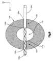
ここで図10A~図12を参照すると、ディスプレイ212はまた、解剖学的構造124の1つ又は2つ以上の部分に対する切断先端部226aの深さの可視指示、例えば深さゲージ画像262を提供するように構成され得る。一例では、図9を参照すると、解剖学的構造124は、第1の皮質、つまり近位皮質123、及び穿孔の方向であり得る、第1の方向D1、つまりX線の進行方向128に沿って第1の皮質123の反対側にある第2の皮質、つまり遠位皮質127を画定する。第1の皮質123は、第1の表面、つまり近位表面123aと、第1の方向D1に沿って第1の表面123aの反対側にある第2の表面、つまり遠位表面123bと、を画定し得る。同様に、第2の皮質127は、第1の表面、つまり近位表面127a、及びX線の進行方向128沿いでもあり得る第1の方向D1に沿って第1の表面127aの反対側にある第2の表面、つまり遠位表面127bを画定し得る。解剖学的構造124は中空部分131を画定し得る。例えば、中空部分131は、第1の皮質123の第2の表面123bと第2の皮質127の第1の表面127bとの間に画定され得る。深さの可視指示、例えば深さゲージ画像262は、切断器具226、特に切断先端部226aが解剖学的構造124に進入するときに変化し得る。具体的には、深さゲージ画像262は、切断器具先端部226aが第1の皮質123及び第2の皮質127のそれぞれの第1の表面及び第2の表面に接触するときに変化し得るデータを含むことができる。10A-12, the
例示的な操作では、例示的な深さゲージ画面1000a及び例示的な分割画面1200をそれぞれ示す図10A及び図12をまず参照すると、深さゲージ画像262は、解剖学的構造124の一部分に対する基準位置の第1の距離を測定するように構成されており、ディスプレイ212は、解剖学的構造124の該一部分に対する切断先端部226aの第2の距離を示すように構成されている。深さゲージ250は、外科用器具203の穿孔時に第1の距離を測定するように構成され得る。ディスプレイ212は、第2の距離をリアルタイムで示すように、外科用器具の穿孔時に第2の距離を示すように構成され得る。第1の皮質123は、解剖学的構造124の一部分を画定することができる。一例では、第1の皮質123、特に第1の皮質123の第1の表面123aは、基準位置からの距離が深さゲージ250によって測定される基準位置を画定する。一例では、切断先端部226aは、第1の距離が第2の距離に等しいように、基準位置を画定する。In an exemplary operation, referring first to FIGS. 10A and 12, which show an exemplary
代替例では、外科用器具203は、第1の距離が第2の距離よりも大きいように、解剖学的構造124の一部分からの距離が深さゲージ250によって測定される基準位置を画定するドリルスリーブを含み得る。切断器具226は、他の理由の中でも、骨を取り囲む軟組織を保護するためにスリーブ内に配置され得る。穿孔中、深さゲージ250は、ドリルスリーブの末端部から第1の皮質123の第1の表面123aまでの距離を決定することができる。ドリルスリーブの末端部から第1の皮質の第1の表面123aまでの距離は、切断先端部226aから第1の皮質123の第1の表面123aまでの距離よりも大きくてもよい。したがって、深さゲージ250は、ディスプレイ212が表示するリアルタイムのドリル深さ距離よりも大きいリアルタイムのドリル深さ距離を測定することができる。第1の距離と第2の距離との差は、切断先端部226aとドリルスリーブの末端部との間の距離(オフセット距離と称され得る)を考慮するように、ディスプレイ212を較正することによって決定され得、ディスプレイ212は、切断器具先端部から第1の皮質123の第1の表面123aまでの距離を示す総ドリル深さ表示264を提供する。一例では、ユーザは、ユーザインターフェース216で較正オプションを選択することによってオフセット距離を入力することができる。別の例では、深さゲージ250は、較正モード中にオフセット距離を決定することができる。In an alternative example, the
ディスプレイ212は、深さゲージ画面1000a及び例示的な分割画面1000を表示することができる。図示の例では、切断器具先端部226aが第1の皮質123の第1の表面123aに当接するときに、総ドリル深さ表示264はゼロ(0)を示す。あるいは、深さゲージは、ドリルスリーブが第1の皮質123の第1の表面123aに当接するときに、総ドリル深さ表示264がゼロ(0)を示し得るように較正され得る。外科用器具203は、第1の皮質123から第2の皮質127に向かって第1の方向D1に穿孔するように構成され得る。したがって、総ドリル深さ表示264は、穿孔操作前にゼロ(0)を示すことができ、それによって切断器具先端部226aは、穿孔操作中に解剖学的構造124に入る。穿孔操作が進行し、切断器具先端部226aが第1の皮質123を通って移動するときの例示的な深さゲージ画面1000b及び例示的な分割画面1100をそれぞれ示す、図10B及び図11を更に参照すると、総ドリル深さ表示264は、切断器具先端226aが第1の皮質123の第1の表面123aに対して進んだリアルタイム距離を示すように増加し得る。図示のように、深さゲージ画像262の表示はミリメートルでレンダリングされるが、表示は任意の代替単位でレンダリングされてもよいことが理解されるであろう。The
深さゲージ画像262は、直近に穿孔された皮質の遠位表面までの切断器具先端部226aからの距離を示す、最近の皮質出口点表示266を更に含み得る。したがって、ディスプレイ212は、切断先端部226aが第1の皮質123を出るときに第3の距離を示すように構成され得、第3の距離は、第1の方向D1に沿った第1の皮質123の幅を表し得る。一例として、切断器具先端部226aが、第1の皮質123の第2の表面123bから出るように、X線の進行方向128であり得る第1の方向D1に沿って進むとき、最近の皮質出口点表示266は、第1の皮質123の第1の表面123aから第1の皮質123の第2の表面123bまでの距離を示す。したがって、一例では、切断器具先端部226aが第1の皮質123の第2の表面123bを通って進む瞬間に、最近の皮質出口点表示266は、総穿孔深さ指示264と同じ値を示し得る。The
穿孔操作の例を続けると、切断器具先端部226aが、第2の皮質127の第2の表面127bから出るように第1の方向D1に沿って進むとき、最近の皮質出口点表示266は、第1の皮質123の第1の表面123aから第2の皮質127の第2の表面127bまでの距離を表示する。したがって、ディスプレイ212は、切断先端部226aが第2の皮質127から出るときに第4の距離を示すように構成され得、第4の距離は、第1の方向D1に沿った骨の骨幅を表し得る。ディスプレイ212は、第2の距離、第3の距離、及び第4の距離を同時に示すように構成され得る。更に、切断器具先端部226aが第2の皮質127の第2の表面127bを通って進む瞬間に、最近の皮質出口点表示266は、総ドリル深さ表示264と同じ値を示し得る。深さゲージ画像262は、以前の皮質出口点ではあるが、直近ではない皮質出口点と関連する表示又は値を表示する、以前の皮質出口点表示268を更に含み得る。したがって、この例を続けると、切断器具先端部226aが第2の皮質127の第2の表面127bを出るとき、以前の皮質出口点268は、第1の皮質123の第1の表面123aから第1の皮質123の第2の表面123bまでの距離を表示する。したがって、最近の皮質出口点表示266に表示された値は、以前の皮質出口点表示268に移る。切断器具先端部226aが第2の皮質127の第2の表面127bから離れるように進むとき、総ドリル深さ表示264は、図10B及び図11に例示されるように、切断器具先端部226aが第1の皮質123の第1の表面123aに対して進んだリアルタイム距離を示すように、増加し得る。Continuing with the example of the drilling operation, as the cutting
理論に束縛されるものではないが、ユーザは、穿孔操作をより良好に行うために、外科用器具203がユーザの制御下で又は自律的にのいずれかで動作している間に、深さゲージ画像262を見ることができる。例えば、ユーザは、総穿孔深さ表示264に基づいて外科用器具を制御するために、穿孔操作の実施中に総ドリル深さ表示264を見ることができる。外科用器具203は、切断器具203が、完全な又は部分的な穿孔が意図されていない軟組織又は遠皮質など解剖学的構造の不要な部分に入らないように、深さゲージ画像262の情報に基づいて制御され得る。場合によっては、ユーザは、穿孔操作の実施後に孔を測定する必要がある代わりに、深さゲージ画像262、特に総穿孔深さ表示264又は最近の皮質出口点表示266を見て、ねじの長さが穿孔されたそれぞれの孔と一致させることができる。一例では、計算装置204は、解剖学的構造124内の孔の深さに基づいて、ねじが穿孔される孔に自動的に一致するように、利用可能なねじの在庫を記憶する。一例では、ユーザは、例えば最近の皮質出口点表示266又は総穿孔深さ表示262など深さゲージ画像262に関する表示のうちの1つに対応するねじが選択されるように、ユーザインターフェース216でねじ選択オプションを作動させることができる。Without being bound by theory, the user may view the
したがって、手術中、ディスプレイ212は、複数のX線画像をリアルタイムで受信し、表示することができ、ディスプレイ212は、外科用器具203の操作時に配向画像129及び深さゲージ画像262、特に総穿孔深さ指示262を表示することができる。具体的には、深さゲージ画像262は、切断器具203が移動する距離を表すことができる。X線透視画像、配向画像、及び深さゲージ画像は、ディスプレイ212によって同時に表示され得る。切断器具203が穿孔方向に沿って移動するときにディスプレイ212によって表示される距離は、距離をリアルタイムで更新するように変化し得る。Thus, during surgery, the
一例では、図6Aを参照すると、外科用器具203は、X線の進行方向128に対して平行である第1の方向D1に沿って、その第1の方向D1に沿って穿孔するように操作され得る。穿孔の間、例えば、切断器具226の配向がゼロ値から離れると、可動インジケータ132は静止領域130から離れる方向に移動し得る。可動インジケータ132は、切断器具226の配向がゼロ値に対して移動するのと同時に静止領域130に対して移動することができ、それにより、可動インジケータ132は、切断器具226の配向のリアルタイム表現を提供する。例えば、切断器具226の近位端部226bが切断器具226の切断先端部226aに対する第2の方向D2に沿って移動するとき、可動インジケータ132は、第2の方向D2に沿って移動し得る(例えば、図5Aを参照)。第2の方向D2は、第1の方向D1に対して垂直であり得る。同様に、切断器具226の近位端部226bが切断器具226の切断先端部226aに対する第3の方向D3に沿って移動するとき、可動インジケータ132は、第3の方向D3に沿って移動し得る(例えば、図5Bを参照)。第3の方向D3は、それぞれ第1の方向D1及び第2の方向D2の両方に対して垂直であり得る。更に、切断器具226の近位端部226bが切断器具226の切断先端部226aに対する第2及び第3の方向の両方に沿って移動するとき、可動インジケータ132は、第2及び第3の方向D3の両方に沿って移動し得ることが理解されよう。更に、配向画面500a~500cは、第2及び第3の方向D2及びD3に沿った切断器具226の配向の数値表現136を含み得る。In one example, referring to FIG. 6A, the
特に図5Cを参照すると、切断器具226がゼロ値に従って配向されるとき、可動式インジケータ132は、静止領域130によって画定される境界内に配置され得る。更に、場合によっては、切断器具226がX線の進行方向128と正確に位置合わせされる場合、数値表現136は、第2及び第3の方向の両方と関連するゼロ値を示し得る。IM釘打ち例として、医療専門家は、標的部位126において適切な配向を有する孔を穿孔するために、図5Cに示す配向画像129を穿孔中に維持し得る。With particular reference to FIG. 5C, when the cutting
開示される技術を実行するための装置の実施形態例が本明細書に記載されているが、根底にある概念は、本明細書に記載されるような情報を通信及び提示することができる任意の計算装置、プロセッサ、又はシステムに適用されてもよい。本明細書に記載される様々な技術は、ハードウェア若しくはソフトウェアに関連して、又は適切な場合にはこれらの両方の組み合わせに関連して実装されてもよい。かくして、本明細書に記載される方法及び装置を実装することができ、又はそれらのある特定の態様又は部分は、フロッピーディスケット、CD-ROM、ハードドライブ、又は任意の他の機械可読記憶媒体(コンピュータ可読記憶媒体)などの有形の非一時的記憶媒体内に具現化されたプログラムコード(即ち、命令)の形態をとることができ、プログラムコードがコンピュータなどの機械にロードされてそれによって実行されると、この機械は、本明細書に記載される技術を実行するための装置になる。プログラマブルコンピュータ上で実行されるプログラムコードの場合、計算装置は、一般に、プロセッサ、プロセッサ可読記憶媒体(揮発性及び不揮発性メモリ、並びに/又は記憶素子を含む)、少なくとも1つの入力装置、及び少なくとも1つの出力装置、例えばディスプレイを含む。ディスプレイは、視覚情報を表示するように構成されてもよい。例えば、表示される視覚情報は、X線画像、X線透視画像、配向画面、又はコンピュータ生成視覚的表現などのX線透視データを含むことができる。Although example embodiments of apparatus for carrying out the disclosed techniques are described herein, the underlying concepts may be applied to any computing device, processor, or system capable of communicating and presenting information as described herein. The various techniques described herein may be implemented in connection with hardware or software, or, where appropriate, a combination of both. Thus, the methods and apparatus described herein may be implemented, or certain aspects or portions thereof, may take the form of program code (i.e., instructions) embodied in a tangible, non-transitory storage medium, such as a floppy diskette, CD-ROM, hard drive, or any other machine-readable storage medium (computer-readable storage medium), which when loaded into and executed by a machine, such as a computer, becomes an apparatus for carrying out the techniques described herein. In the case of program code executed on a programmable computer, a computing device generally includes a processor, a processor-readable storage medium (including volatile and non-volatile memory and/or storage elements), at least one input device, and at least one output device, such as a display. The display may be configured to display visual information. For example, the displayed visual information may include fluoroscopic data, such as an x-ray image, a fluoroscopic image, an orientation screen, or a computer-generated visual representation.
プログラムは、所望によりアセンブリ又は機械語に実装されてもよい。この機械語は、コンパイラ型言語又はインタープリタ型言語であってもよく、ハードウェア実装と組み合わされてもよい。The programs may be implemented in assembly or machine code, if desired. The machine code may be a compiled or interpreted language, and combined with hardware implementations.
本明細書に記載される技術はまた、いくつかの送信媒体を介して、例えば電気配線又はケーブル配線を介して、光ファイバーを通して、又は送信の任意の他の形態を介して送信されるプログラムコードの形態で具現化された通信を介して実施されてもよい。汎用プロセッサ上で実装される場合、プログラムコードはプロセッサと組み合わされて、本明細書に記載される機能性をもたらすように操作する独自の装置を提供する。加えて、本明細書に記載される技術に関連して使用される任意の記憶技術は、常にハードウェアとソフトウェアとの組み合わせであってもよい。The techniques described herein may also be implemented via communication embodied in the form of program code transmitted over some transmission medium, such as over electrical wiring or cabling, through optical fiber, or over any other form of transmission. When implemented on a general-purpose processor, the program code combines with the processor to provide a unique apparatus that operates to provide the functionality described herein. In addition, any storage techniques used in connection with the techniques described herein may invariably be a combination of hardware and software.
本明細書に記載される技術が、様々な図面の様々な実施形態に関連して実施されてもよく、かつ記載されている一方で、他の類似の実施形態が使用されてもよく、又は記載の実施形態に、それから逸脱することなく修正及び追加が加えられてもよいことを理解されたい。例えば、上に開示されるステップが、上に示される順序で、又は所望により任意の他の順序で実行されてもよいことを理解されたい。更に、当業者であれば、本出願に記載される技術が、有線又は無線にかかわらず、任意の環境に適用することができ、通信ネットワークを介して接続され、かつネットワーク全域で情報交換する任意の数のそのような装置に適用され得ることを認識するであろう。したがって、本明細書に記載される技術は、いずれの単一の実施形態にも制限されるべきではなく、むしろ添付の特許請求の範囲に従う広がり及び範囲内で解釈されるべきである。While the techniques described herein may be implemented in connection with and described in various embodiments of the various drawings, it should be understood that other similar embodiments may be used, or modifications and additions may be made to the described embodiments without departing from them. For example, it should be understood that the steps disclosed above may be performed in the order shown above, or in any other order as desired. Furthermore, one skilled in the art will recognize that the techniques described in this application may be applied to any environment, whether wired or wireless, and to any number of such devices connected via a communications network and exchanging information across the network. Thus, the techniques described herein should not be limited to any single embodiment, but rather should be construed in breadth and scope in accordance with the appended claims.
〔実施の態様〕
(1) 外科用器具アセンブリであって、
プロセッサと、
解剖学的構造に作用するように構成された外科用器具と、
前記プロセッサに結合され、前記外科用器具に取り付けられたディスプレイであって、前記解剖学的構造のX線データを表示するように構成されており、前記X線データが医療用撮像装置によって生成されたものである、ディスプレイと、
前記プロセッサと通信するメモリであって、前記メモリが、その中に命令を記憶しており、前記プロセッサを実行すると、前記命令が、前記プロセッサに
髄内釘の同一性を判定するために複数の髄内釘から髄内釘を識別することであって、前記髄内釘が、それぞれの係止ねじを受容するようにサイズ決めされた複数の係止孔を画定する、識別することと、
前記医療用撮像装置から第1のX線画像を受信することであって、前記第1のX線画像は、前記第1のX線画像が前記髄内釘の一部分を含むように、前記医療用撮像装置が第1の位置にあるときに前記医療用撮像装置によって生成されたものであり、前記髄内釘の前記一部分が、前記複数の係止孔のうちの少なくとも2つの係止孔の一部分を含む、受信することと、
前記少なくとも2つの係止孔の前記一部分及び前記髄内釘の同一性に基づいて、前記第1の位置とは異なる前記医療用撮像装置の第2の位置を、前記医療用撮像装置が前記第2の位置に配置され、前記第2の位置から第2のX線画像を生成するとき、前記第2のX線画像がそれぞれの円として示される前記少なくとも2つの係止孔を含むように決定することと、を行わせる、メモリと、を備える外科用器具アセンブリ。
(2) 前記少なくとも2つの係止孔が、前記髄内釘の長さに沿って互いに離間され、前記医療用撮像装置が、X線トランスミッタとX線レシーバとを、前記X線トランスミッタから前記X線レシーバへのX線の進行方向を画定するように含み、前記X線の進行方向は、前記医療用撮像装置が前記第2の位置にあるときに、前記髄内釘の前記長さに対して実質的に垂直である、実施態様1に記載の外科用器具アセンブリ。
(3) 前記メモリがその中に、更なる命令を記憶しており、前記プロセッサを実行すると、前記命令が、前記プロセッサに、
前記医療用撮像装置の前記第1の位置及び前記第2の位置に基づいて調整座標を決定することであって、前記調整座標が、前記第1の位置から前記第2の位置に到達するために前記X線の進行方向がどのように調整されるかを示す、決定することを行わせる、実施態様2に記載の外科用器具アセンブリ。
(4) 前記ディスプレイが、前記調整座標を表示するように更に構成されている、実施態様3に記載の外科用器具アセンブリ。
(5) 前記ディスプレイが、前記X線トランスミッタ及び前記X線レシーバの実際の位置に対応する位置座標を表示するように更に構成され、前記位置座標は、前記X線トランスミッタ及び前記X線レシーバの前記実際の位置が調整されたときに、前記医療用撮像装置から受信され、それにより、表示される前記位置座標は、前記X線トランスミッタ及び前記X線レシーバが移動したときに変化する、実施態様4に記載の外科用器具アセンブリ。[Embodiment]
(1) A surgical instrument assembly, comprising:
A processor;
a surgical instrument configured to act on an anatomical structure;
a display coupled to the processor and attached to the surgical instrument, the display configured to display x-ray data of the anatomical structure, the x-ray data being generated by a medical imaging device; and
a memory in communication with the processor, the memory having instructions stored therein that, when executed by the processor, cause the processor to: identify an intramedullary nail from a plurality of intramedullary nails to determine an identity of the intramedullary nail, the intramedullary nail defining a plurality of locking holes sized to receive respective locking screws;
receiving a first x-ray image from the medical imaging device, the first x-ray image being generated by the medical imaging device when the medical imaging device was in a first position such that the first x-ray image includes a portion of the intramedullary nail, the portion of the intramedullary nail including portions of at least two of the plurality of locking holes;
and determining a second position of the medical imaging device, different from the first position, based on the portion of the at least two locking holes and an identity of the intramedullary nail, such that when the medical imaging device is placed at the second position and a second X-ray image is generated from the second position, the second X-ray image includes the at least two locking holes shown as respective circles.
2. The surgical instrument assembly of claim 1, wherein the at least two locking holes are spaced apart from one another along a length of the intramedullary nail, and the medical imaging device includes an x-ray transmitter and an x-ray receiver to define a direction of travel of x-rays from the x-ray transmitter to the x-ray receiver, the direction of travel of x-rays being substantially perpendicular to the length of the intramedullary nail when the medical imaging device is in the second position.
(3) the memory has further instructions stored therein, the instructions, when executed by the processor, causing the processor to:
3. The surgical instrument assembly of claim 2, further comprising: determining an adjustment coordinate based on the first position and the second position of the medical imaging device, the adjustment coordinate indicating how a direction of travel of the X-rays is adjusted to reach the second position from the first position.
(4) The surgical instrument assembly according to claim 3, wherein the display is further configured to display the adjustment coordinates.
5. The surgical instrument assembly of claim 4, wherein the display is further configured to display position coordinates corresponding to actual positions of the X-ray transmitter and the X-ray receiver, the position coordinates being received from the medical imaging device when the actual positions of the X-ray transmitter and the X-ray receiver are adjusted, whereby the displayed position coordinates change when the X-ray transmitter and the X-ray receiver are moved.
(6) 前記ディスプレイは、前記プロセッサが前記医療用撮像装置から前記第1のX線画像を受信したことに応答して、前記第2の位置を示すように更に構成されている、実施態様1に記載の外科用器具アセンブリ。
(7) 前記メモリが、その中に命令を更に記憶しており、前記プロセッサを実行すると、前記命令が、前記プロセッサに、
前記医療用撮像装置の第3の位置を、前記医療用撮像装置が前記第3の位置に配置され、前記第3の位置から第3のX線画像を生成するときに、前記第3のX線画像が円として示される前記髄内釘の第3の係止孔を含むように決定することであって、前記第3の係止孔が前記少なくとも2つの係止孔とは異なる、決定することを更に行わせる、実施態様1に記載の外科用器具アセンブリ。
(8) 前記ディスプレイは、前記プロセッサが前記医療用撮像装置から前記第1のX線画像を受信したことに応答して、前記第3の位置を示すように更に構成されている、実施態様7に記載の外科用器具アセンブリ。
(9) 前記少なくとも2つの係止孔の前記一部分が、前記第1のX線画像上でそれぞれの楕円として視認可能である、実施態様1に記載の外科用器具アセンブリ。
(10) 前記第1のX線画像の前記髄内釘の前記一部分が、2つの係止孔のみを含む、実施態様1に記載の外科用器具アセンブリ。6. The surgical instrument assembly of claim 1, wherein the display is further configured to indicate the second position in response to the processor receiving the first x-ray image from the medical imaging device.
(7) The memory further stores therein instructions, the instructions causing the processor to:
2. The surgical instrument assembly of claim 1, further comprising determining a third position of the medical imaging device such that when the medical imaging device is disposed at the third position and a third X-ray image is generated from the third position, the third X-ray image includes a third locking hole of the intramedullary nail shown as a circle, the third locking hole being different from the at least two locking holes.
8. The surgical instrument assembly of claim 7, wherein the display is further configured to indicate the third position in response to the processor receiving the first x-ray image from the medical imaging device.
9. The surgical instrument assembly of claim 1, wherein the portions of the at least two locking holes are visible as respective ellipses on the first x-ray image.
10. The surgical instrument assembly of claim 1, wherein the portion of the intramedullary nail in the first x-ray image includes only two locking holes.
(11) 前記X線画像に示される前記2つの係止孔の前記一部分が、前記2つの係止孔の30%未満である、実施態様10に記載の外科用器具アセンブリ。
(12) 髄内釘を骨に固定するために係止ねじ用の孔を穿孔する向きを決定するための方法であって、
無線通信チャネルを介して、前記骨及び前記骨内にある前記髄内釘の一部分の第1のX線画像を受信するステップであって、前記第1のX線画像は、医療用撮像装置が第1の位置にある間に、前記医療用撮像装置によって生成され、前記第1のX線画像が、前記髄内釘によって画定された少なくとも係止孔の第1の視覚的視点を含む、受信するステップと、
前記髄内釘の物理的特徴を取得するステップと、
前記少なくとも2つの係止孔の前記第1の視覚的視点に基づいて、かつ前記髄内釘の前記物理的特徴に基づいて、前記医療用撮像装置の第2の位置を決定するステップと、を含み、
前記医療用撮像装置が前記第2の位置にある間に前記医療用撮像装置が第2のX線画像を生成するとき、前記第2のX線画像が、前記少なくとも2つの係止孔の第2の視覚的視点を含み、前記第2の視覚的視点が、前記少なくとも2つの係止孔のそれぞれの外周に対応する円を画定する、方法。
(13) 前記第1の視覚的視点が、前記少なくとも2つの係止孔のそれぞれの外周に対応する楕円又はレンズを画定する、実施態様12に記載の方法。
(14) 前記少なくとも2つの係止孔の前記第1の視覚的視点に基づいて、かつ前記髄内釘の前記物理的特徴に基づいて、前記医療用撮像装置の第3の位置を決定することを更に含み、
前記医療用撮像装置が前記第3の位置にある間に前記医療用撮像装置が第3のX線画像を生成するとき、前記第3のX線画像が、前記髄内釘の第3の係止孔の第3の視覚的視点を含み、前記第3の係止孔が前記第1のX線画像において可視ではなく、前記第3の視覚的視点が、前記第3の係止孔の外周に対応する円を画定する、実施態様12に記載の方法。
(15) 髄内釘を骨に固定するために係止ねじ用の孔を穿孔する方法であって、
前記髄内釘に対して医療用撮像装置を第1の位置に配することと、
前記医療用撮像装置が前記第1の位置にある間に、前記骨の第1のX線画像を生成することであって、前記第1のX線画像が前記髄内釘の一部分を含み、前記髄内釘の前記一部分が、前記髄内釘によって画定された係止孔の第1の視覚的視点を含む、生成することと、
前記係止孔の前記第1の視覚的視点に基づいて、前記髄内釘に対する前記医療用撮像装置の第2の位置を決定することと、
前記医療用撮像装置を前記髄内釘に対して前記第2の位置に配することと、
前記医療用撮像装置が前記第2の位置にある間に、前記骨の第2のX線画像を生成することと、を含み、
前記第2のX線画像が前記係止孔の第2の視覚的視点を含み、前記第2の視覚的視点が、前記係止孔の外周に対応する円を画定する、方法。11. The surgical instrument assembly of claim 10, wherein the portion of the two locking holes shown in the x-ray image is less than 30% of the two locking holes.
(12) A method for determining an orientation for drilling a hole for a locking screw to fix an intramedullary nail to a bone, comprising:
receiving, via a wireless communication channel, a first x-ray image of the bone and a portion of the intramedullary nail within the bone, the first x-ray image being generated by the medical imaging device while the medical imaging device is in a first position, the first x-ray image including a first visual perspective of at least a locking hole defined by the intramedullary nail;
obtaining a physical characteristic of the nail;
determining a second position of the medical imaging device based on the first visual perspective of the at least two locking holes and based on the physical characteristics of the nail;
The method, wherein when the medical imaging device generates a second X-ray image while the medical imaging device is in the second position, the second X-ray image includes a second visual perspective of the at least two engagement holes, the second visual perspective defining a circle corresponding to an outer periphery of each of the at least two engagement holes.
13. The method of
determining a third position of the medical imaging device based on the first visual perspective of the at least two locking holes and based on the physical characteristics of the nail;
13. The method of
(15) A method for drilling a hole for a locking screw to fix an intramedullary nail to a bone, comprising:
Positioning a medical imaging device at a first position relative to the nail;
generating a first x-ray image of the bone while the medical imaging device is in the first position, the first x-ray image including a portion of the nail, the portion of the nail including a first visual perspective of a locking hole defined by the nail;
determining a second position of the medical imaging device relative to the nail based on the first visual perspective of the locking hole;
positioning the medical imaging device at the second position relative to the nail;
generating a second x-ray image of the bone while the medical imaging device is in the second position;
The method, wherein the second x-ray image includes a second visual perspective of the locking hole, the second visual perspective defining a circle corresponding to a periphery of the locking hole.
(16) 前記医療用撮像装置が、前記係止孔の前記第2の視覚的視点の前記円の外周によって画定される平面に対して実質的に垂直であるX線の進行方向を画定するように、前記医療用撮像装置を前記第2の位置に配することを更に含む、実施態様15に記載の方法。
(17) 前記医療用撮像装置によって支持された運動センサを更に備え、前記運動センサが、前記医療用撮像装置のX線発生器からX線レシーバへのX線の進行方向を用いて加速度計を較正するために、前記X線の進行方向の向きを決定するように構成されている、実施態様16に記載の外科用器具アセンブリ。
(18) 前記医療用撮像装置が前記第2の位置にあるときに、前記医療用撮像装置によって画定された前記X線の進行方向に沿って前記孔を穿孔することを更に含む、実施態様16に記載の方法。
(19) 前記第2の位置が前記第1のX線画像及び前記髄内釘の物理的特徴にのみ基づいて決定されるように、前記髄内釘の前記物理的特徴に更に基づいて、前記医療用撮像装置の前記第2の位置を決定することを更に含む、実施態様15に記載の方法。
(20) 前記第2の位置の指示を表示することを更に含み、前記医療用撮像装置が、前記第1の位置から前記第2の位置に位置的に調整可能である、実施態様15に記載の方法。16. The method of claim 15, further comprising positioning the medical imaging device in the second position such that the medical imaging device defines a direction of x-ray travel that is substantially perpendicular to a plane defined by a circumference of the circle of the second visual perspective of the locking hole.
17. The surgical instrument assembly of claim 16, further comprising a motion sensor supported by the medical imaging device, the motion sensor configured to determine an orientation of a direction of travel of x-rays from an x-ray generator to an x-ray receiver of the medical imaging device to calibrate an accelerometer with the direction of travel of x-rays.
18. The method of claim 16, further comprising drilling the holes along a direction of travel of the x-rays defined by the medical imaging device when the medical imaging device is in the second position.
19. The method of claim 15, further comprising determining the second position of the medical imaging device further based on the physical characteristics of the nail, such that the second position is determined based only on the first x-ray image and physical characteristics of the nail.
20. The method of claim 15, further comprising displaying an indication of the second position, wherein the medical imaging device is positionally adjustable from the first position to the second position.
Claims (18)
Translated fromJapaneseプロセッサと、
解剖学的構造に作用するように構成された外科用器具と、
前記プロセッサに結合され、前記外科用器具に取り付けられたディスプレイであって、前記解剖学的構造のX線データを表示するように構成されており、前記X線データが医療用撮像装置によって生成されたものである、ディスプレイと、
前記プロセッサと通信するメモリであって、前記メモリが、その中に命令を記憶しており、前記プロセッサを実行すると、前記命令が、前記プロセッサに
オプションとして選択可能な複数の髄内釘のいずれかと、手術で使用される髄内釘の同一性を識別することであって、前記髄内釘が、それぞれの係止ねじを受容するようにサイズ決めされた複数の係止孔を画定する、識別することと、
前記医療用撮像装置から第1のX線画像を受信することであって、前記第1のX線画像は、前記第1のX線画像が前記髄内釘の一部分を含むように、前記医療用撮像装置が第1の位置にあるときに前記医療用撮像装置によって生成されたものであり、前記髄内釘の前記一部分が、前記複数の係止孔のうちの少なくとも2つの係止孔の一部分を含む、受信することと、
前記少なくとも2つの係止孔のそれぞれの外周に対応する楕円又はレンズを画定する前記第1のX線画像及び前記髄内釘の前記同一性に基づいて、前記第1の位置とは異なる前記医療用撮像装置の第2の位置を、前記医療用撮像装置が前記第2の位置に配置され、前記第2の位置から第2のX線画像を生成するとき、前記第2のX線画像がそれぞれの円として示される前記少なくとも2つの係止孔を含むように決定することと、を行わせる、メモリと、を備える外科用器具アセンブリ。 1. A surgical instrument assembly comprising:
A processor;
a surgical instrument configured to act on an anatomical structure;
a display coupled to the processor and attached to the surgical instrument, the display configured to display x-ray data of the anatomical structure, the x-ray data being generated by a medical imaging device; and
a memory in communication with the processor, the memory having instructions stored therein, the instructions being executed by the processor to
identifyingthe identity of the intramedullary nailto be used in the procedure as any of a plurality ofoptional intramedullary nails, the intramedullary nail defining a plurality of locking holes sized to receive respective locking screws;
receiving a first x-ray image from the medical imaging device, the first x-ray image being generated by the medical imaging device when the medical imaging device was in a first position such that the first x-ray image includes a portion of the intramedullary nail, the portion of the intramedullary nail including portions of at least two of the plurality of locking holes;
and determining a second position of the medical imaging device, different from the first position, based onthe first X-ray image defining an ellipse or lens corresponding to the outer periphery of eachof the at least two locking holes and the identity of the intramedullary nail, such that when the medical imaging device is placed at the second position and a second X-ray image is generated from the second position, the second X-ray image includes the at least two locking holes shown as respective circles.
前記医療用撮像装置の前記第1の位置及び前記第2の位置に基づいて調整座標を決定することであって、前記調整座標が、前記第1の位置から前記第2の位置に到達するために前記X線の進行方向がどのように調整されるかを示す、決定することを行わせる、請求項2に記載の外科用器具アセンブリ。 The memory has further instructions stored therein, thefurther instructions, when executed by the processor, causing the processor to:
3. The surgical instrument assembly of claim 2, further comprising: determining adjustment coordinates based on the first and second positions of the medical imaging device, the adjustment coordinates indicating how a direction of travel of the x-rays is adjusted to reach the second position from the first position.
前記医療用撮像装置の第3の位置を、前記医療用撮像装置が前記第3の位置に配置され、前記第3の位置から第3のX線画像を生成するときに、前記第3のX線画像が円として示される前記髄内釘の第3の係止孔を含むように決定することであって、前記第3の係止孔が前記少なくとも2つの係止孔とは異なる、決定することを更に行わせる、請求項1に記載の外科用器具アセンブリ。 The memory hasfurther instructions stored therein, thefurther instructions, when executed by the processor, causing the processor to:
2. The surgical instrument assembly of claim 1, further comprising determining a third position of the medical imaging device such that when the medical imaging device is disposed at the third position and a third X-ray image is generated from the third position, the third X-ray image includes a third locking hole of the intramedullary nail shown as a circle, the third locking hole being different from the at least two locking holes.
前記外科用器具アセンブリのプロセッサが、前記外科用器具アセンブリの無線通信チャネルを介して、前記骨及び前記骨内にある前記髄内釘の一部分の第1のX線画像を受信するステップであって、前記第1のX線画像は、医療用撮像装置が第1の位置にある間に、前記医療用撮像装置によって生成され、前記第1のX線画像が、前記髄内釘によって画定された少なくとも2つの係止孔の第1の視覚的視点を含む、受信するステップと、
前記プロセッサが、前記髄内釘の物理的特徴を取得するステップと、
前記プロセッサが、前記少なくとも2つの係止孔のそれぞれの外周に対応する楕円又はレンズを画定する前記第1の視覚的視点に基づいて、かつ前記髄内釘の前記少なくとも2つの係止孔の位置及びサイズを含む前記物理的特徴に基づいて、前記少なくとも2つの係止孔のいずれかの外周に対応する円を画定し得る前記医療用撮像装置の第2の位置を決定するステップと、を含み、
前記医療用撮像装置が前記第2の位置にある間に前記医療用撮像装置が第2のX線画像を生成するとき、前記第2のX線画像が、前記少なくとも2つの係止孔の第2の視覚的視点を含み、前記第2の視覚的視点が、前記少なくとも2つの係止孔のそれぞれの外周に対応する円を画定する、外科用器具アセンブリの作動方法。 1. A methodof operating a surgical instrument assembly for orienting a hole for a locking screw to secure an intramedullary nail to a bone, comprising:
receiving, by a processor of the surgical instrument assembly, via a wireless communication channel of the surgical instrument assembly , a first x-ray image of the bone and a portion of the intramedullary nail within the bone, the first x-ray image being generated by the medical imaging device while the medical imaging device is in a first position, the first x-ray image including a first visual perspective of at leasttwo locking holes defined by the intramedullary nail;
said processor acquiring physical characteristics of said nail;
and determining a second position ofthe medical imaging device based on the first visual viewpointthat defines an ellipse or lens corresponding to an outer periphery of each of the at least two locking holes and based on the physical characteristics of the nail including a position and a size of the at least two locking holes, the second position of the medical imaging devicemay define a circle corresponding to an outer periphery of any of the at least two locking holes ,
A method of operating a surgical instrument assembly, wherein when the medical imaging device generates a second X-ray image while the medical imaging device is in the second position, the second X-ray image includes a second visual perspective of the at least two locking holes, the second visual perspective defining a circle corresponding to an outer periphery of each of the at least twolocking holes.
前記プロセッサが、前記医療用撮像装置が前記第3の位置にある間に前記医療用撮像装置が第3のX線画像を生成するとき、前記第3のX線画像が、前記髄内釘の前記第3の係止孔の第3の視覚的視点を含み、前記第3の係止孔が前記第1のX線画像において可視ではなく、前記第3の視覚的視点が、前記第3の係止孔の外周に対応する円を画定する、請求項11に記載の外科用器具アセンブリの作動方法。The processor further includesdetermining a third position of the medical imaging device that can represent a third lockinghole of the intramedullary nail as a perfect circle based on the first visual viewpoint thatdefines an ellipse or lens corresponding to an outer periphery of each of the at least two locking holes and based on the physical characteristics of the intramedullary nail including a position and a sizeof the at least two locking holes, the third locking hole being different from the at least two locking holes ;
12. The method of operatinga surgical instrument assembly according to claim 11, wherein the processor determines that when the medical imaging device generates a third X-ray image while the medical imaging device is in the thirdposition , the third X-ray image includes a third visual perspective of the third locking hole ofthe intramedullary nail , the third locking hole being not visible in the first X-ray image, and thethird visual perspective defining a circle corresponding to a circumference of the third locking hole.
前記外科用器具アセンブリのプロセッサが、医療用撮像装置が前記髄内釘に対する第1の位置にある間に、前記骨の第1のX線画像を生成することであって、前記第1のX線画像が前記髄内釘の一部分を含み、前記髄内釘の前記一部分が、前記髄内釘によって画定された係止孔の第1の視覚的視点を含む、生成することと、
前記プロセッサが、前記係止孔の外周に対応する楕円又はレンズを画定する前記第1の視覚的視点に基づいて、前記係止孔の外周に対応する円を画定し得る前記髄内釘に対する前記医療用撮像装置の第2の位置を決定することと、
前記プロセッサが、前記医療用撮像装置が前記第2の位置にある間に、前記骨の第2のX線画像を生成することと、を含み、
前記第2のX線画像が前記係止孔の第2の視覚的視点を含み、前記係止孔の外周に対応する楕円又はレンズを画定する前記第2の視覚的視点が、前記係止孔の外周に対応する円を画定する、外科用器具アセンブリの作動方法。 1. A methodof operating a surgical instrument assembly fordefining a holelocation for a locking screw to secure an intramedullary nail to a bone, comprising:
a processor of the surgical instrument assembly generating a first x-ray image of the bone while a medical imaging device is in a first positionrelative to the nail , the first x-ray image including a portion of the nail, the portion of the nail including a first visual perspective of a locking hole defined by the nail;
determining a second position of the medical imaging device relative to the nail, the second positionmay define a circle corresponding to a periphery of the locking hole based on the first visual viewpoint, the second position defining an ellipse or a lens corresponding to a periphery of the locking hole;
generating a second x-ray image of the bone while the medical imagingdevice is in the second position;
A method of operating a surgical instrument assembly, wherein the second x-ray image includes a second visual perspective of the locking hole, the second visual perspectivedefining an ellipse or lens corresponding to an outer periphery of the locking hole , the secondvisual perspective defining a circle corresponding to an outer periphery of the locking hole.
Applications Claiming Priority (3)
| Application Number | Priority Date | Filing Date | Title |
|---|---|---|---|
| US16/536,773 | 2019-08-09 | ||
| US16/536,773US11559359B2 (en) | 2019-08-09 | 2019-08-09 | Surgical instrument mounted display system |
| PCT/IB2020/057446WO2021028796A1 (en) | 2019-08-09 | 2020-08-06 | Surgical instrument mounted display system |
Publications (2)
| Publication Number | Publication Date |
|---|---|
| JP2022543869A JP2022543869A (en) | 2022-10-14 |
| JP7589229B2true JP7589229B2 (en) | 2024-11-25 |
Family
ID=72046970
Family Applications (1)
| Application Number | Title | Priority Date | Filing Date |
|---|---|---|---|
| JP2022507853AActiveJP7589229B2 (en) | 2019-08-09 | 2020-08-06 | Surgical Instrument Wearable Display System |
Country Status (8)
| Country | Link |
|---|---|
| US (2) | US11559359B2 (en) |
| EP (2) | EP4437998A3 (en) |
| JP (1) | JP7589229B2 (en) |
| CN (1) | CN114599287A (en) |
| AU (1) | AU2020327694A1 (en) |
| BR (1) | BR112022002396A2 (en) |
| CA (1) | CA3148153A1 (en) |
| WO (1) | WO2021028796A1 (en) |
Families Citing this family (6)
| Publication number | Priority date | Publication date | Assignee | Title |
|---|---|---|---|---|
| US11559359B2 (en)* | 2019-08-09 | 2023-01-24 | DePuy Synthes Products, Inc. | Surgical instrument mounted display system |
| US11882365B2 (en)* | 2021-02-18 | 2024-01-23 | Canon U.S.A., Inc. | Continuum robot apparatus, method, and medium |
| FR3124942B1 (en)* | 2021-07-08 | 2024-11-22 | Amplitude | System for assisting in fixing a surgical implant in a patient's bone. |
| WO2023135491A1 (en)* | 2022-01-12 | 2023-07-20 | DePuy Synthes Products, Inc. | X-wing enhanced guidance system for distal targeting |
| US12201379B2 (en) | 2022-01-12 | 2025-01-21 | DePuy Synthes Products, Inc. | X-wing enhanced guidance system for distal targeting |
| WO2023244566A2 (en)* | 2022-06-13 | 2023-12-21 | Stryker Corporation | Trajectory guidance of hand-held surgical tools during a surgical procedure |
Citations (3)
| Publication number | Priority date | Publication date | Assignee | Title |
|---|---|---|---|---|
| JP2005529667A (en) | 2002-06-17 | 2005-10-06 | メイザー サージカル テクノロジーズ リミテッド | Robots for use with orthopedic inserts |
| JP2018011982A (en) | 2007-02-28 | 2018-01-25 | スミス アンド ネフュー インコーポレイテッド | System and method for identifying object |
| US20190082178A1 (en) | 2016-03-30 | 2019-03-14 | Electronics And Telecommunications Research Institute | Method and apparatus for encoding and decoding video using picture division information |
Family Cites Families (30)
| Publication number | Priority date | Publication date | Assignee | Title |
|---|---|---|---|---|
| US5031203A (en) | 1990-02-09 | 1991-07-09 | Trecha Randal R | Coaxial laser targeting device for use with x-ray equipment and surgical drill equipment during surgical procedures |
| US6718194B2 (en) | 2000-11-17 | 2004-04-06 | Ge Medical Systems Global Technology Company, Llc | Computer assisted intramedullary rod surgery system with enhanced features |
| US7060075B2 (en) | 2002-07-18 | 2006-06-13 | Biosense, Inc. | Distal targeting of locking screws in intramedullary nails |
| US7660623B2 (en)* | 2003-01-30 | 2010-02-09 | Medtronic Navigation, Inc. | Six degree of freedom alignment display for medical procedures |
| EP1491150A1 (en)* | 2003-06-27 | 2004-12-29 | Universite Libre De Bruxelles | Method of acquiring informations in order to insert a locking screw in a hole of a metallic object |
| US8064660B2 (en) | 2004-02-27 | 2011-11-22 | National University Of Singapore | Method and system for detection of bone fractures |
| ITMI20040695A1 (en)* | 2004-04-08 | 2004-07-08 | Teleios S R L | AUTOMATIC POINTING EQUIPMENT FOR THE CORRECT POSITIONING OF THE DISTAL LOCKING SCREWS OF AN ENDOMIDOLLAR NAIL |
| WO2006091494A1 (en)* | 2005-02-22 | 2006-08-31 | Mako Surgical Corp. | Haptic guidance system and method |
| US9402639B2 (en)* | 2005-12-14 | 2016-08-02 | General Electric Company | Method and apparatus for alignment of a mobile fluoroscopic imaging system |
| EP2023811B1 (en) | 2006-05-17 | 2018-08-08 | NuVasive, Inc. | Surgical trajectory monitoring system |
| EP2051647B1 (en)* | 2006-08-15 | 2010-12-01 | AO Technology AG | Method and device for computer assisted distal locking of intramedullary nails |
| JP2010537673A (en) | 2007-05-04 | 2010-12-09 | スミス アンド ネフュー インコーポレーテッド | Surgical camera system |
| DE112008002851B4 (en)* | 2007-10-24 | 2018-06-21 | Nuvasive, Inc. | Surgical pathway monitoring system and related procedures |
| US9031637B2 (en)* | 2009-04-27 | 2015-05-12 | Smith & Nephew, Inc. | Targeting an orthopaedic implant landmark |
| BR112013021042B1 (en) | 2011-02-18 | 2021-08-17 | DePuy Synthes Products, LLC | MANUAL TOOL |
| US9498231B2 (en) | 2011-06-27 | 2016-11-22 | Board Of Regents Of The University Of Nebraska | On-board tool tracking system and methods of computer assisted surgery |
| US9687308B2 (en) | 2011-12-15 | 2017-06-27 | AO Technolgoy AG | Method and a device for computer assisted surgery |
| US9241682B2 (en)* | 2013-03-12 | 2016-01-26 | Depuy Synthes Products, Inc | Apparatus and method for calibrating an x-ray image of a knee of a patient |
| US9301723B2 (en)* | 2013-03-15 | 2016-04-05 | Covidien Lp | Microwave energy-delivery device and system |
| GB201320019D0 (en) | 2013-11-13 | 2013-12-25 | Univ Singapore | Method and hand held laboratory device to control screen navigation |
| US20160030062A1 (en) | 2014-07-29 | 2016-02-04 | Rich Technologies, LLC | Hole locating system |
| US10013808B2 (en) | 2015-02-03 | 2018-07-03 | Globus Medical, Inc. | Surgeon head-mounted display apparatuses |
| WO2017062466A2 (en) | 2015-10-05 | 2017-04-13 | Stryker Corporation | Sterilizable enclosure for securing a portable electronic device |
| WO2017083989A1 (en) | 2015-11-16 | 2017-05-26 | Ao Technology Ag | Surgical power drill including a measuring unit suitable for bone screw length determination |
| JP6876065B2 (en)* | 2015-12-14 | 2021-05-26 | ニューヴェイジヴ,インコーポレイテッド | 3D visualization during surgery with reduced radiation |
| TWI572322B (en)* | 2015-12-16 | 2017-03-01 | The method of positioning the fixation hole of bone marrow | |
| US10517612B2 (en)* | 2017-09-19 | 2019-12-31 | Biosense Webster (Israel) Ltd. | Nail hole guiding system |
| US11166766B2 (en)* | 2017-09-21 | 2021-11-09 | DePuy Synthes Products, Inc. | Surgical instrument mounted display system |
| US11259771B2 (en)* | 2019-01-03 | 2022-03-01 | Brainlab Ag | Determining a target position of an X-ray device |
| US11559359B2 (en)* | 2019-08-09 | 2023-01-24 | DePuy Synthes Products, Inc. | Surgical instrument mounted display system |
- 2019
- 2019-08-09USUS16/536,773patent/US11559359B2/enactiveActive
- 2020
- 2020-08-06BRBR112022002396Apatent/BR112022002396A2/enunknown
- 2020-08-06CNCN202080056575.9Apatent/CN114599287A/enactivePending
- 2020-08-06EPEP24194174.9Apatent/EP4437998A3/ennot_activeWithdrawn
- 2020-08-06CACA3148153Apatent/CA3148153A1/enactivePending
- 2020-08-06AUAU2020327694Apatent/AU2020327694A1/enactivePending
- 2020-08-06WOPCT/IB2020/057446patent/WO2021028796A1/ennot_activeCeased
- 2020-08-06EPEP20754389.3Apatent/EP4009883B1/enactiveActive
- 2020-08-06JPJP2022507853Apatent/JP7589229B2/enactiveActive
- 2022
- 2022-12-19USUS18/067,759patent/US11839437B2/enactiveActive
Patent Citations (3)
| Publication number | Priority date | Publication date | Assignee | Title |
|---|---|---|---|---|
| JP2005529667A (en) | 2002-06-17 | 2005-10-06 | メイザー サージカル テクノロジーズ リミテッド | Robots for use with orthopedic inserts |
| JP2018011982A (en) | 2007-02-28 | 2018-01-25 | スミス アンド ネフュー インコーポレイテッド | System and method for identifying object |
| US20190082178A1 (en) | 2016-03-30 | 2019-03-14 | Electronics And Telecommunications Research Institute | Method and apparatus for encoding and decoding video using picture division information |
Also Published As
| Publication number | Publication date |
|---|---|
| US20230118881A1 (en) | 2023-04-20 |
| AU2020327694A1 (en) | 2022-03-31 |
| EP4009883C0 (en) | 2024-08-14 |
| EP4009883A1 (en) | 2022-06-15 |
| JP2022543869A (en) | 2022-10-14 |
| US20210038178A1 (en) | 2021-02-11 |
| CN114599287A (en) | 2022-06-07 |
| US11839437B2 (en) | 2023-12-12 |
| CA3148153A1 (en) | 2021-02-18 |
| BR112022002396A2 (en) | 2022-07-05 |
| WO2021028796A1 (en) | 2021-02-18 |
| EP4437998A3 (en) | 2024-11-20 |
| US11559359B2 (en) | 2023-01-24 |
| EP4009883B1 (en) | 2024-08-14 |
| EP4437998A2 (en) | 2024-10-02 |
Similar Documents
| Publication | Publication Date | Title |
|---|---|---|
| JP7589229B2 (en) | Surgical Instrument Wearable Display System | |
| JP7604373B2 (en) | Surgical Instrument Wearable Display System | |
| JP7242646B2 (en) | surgical instrument mounted display system | |
| JP2024170543A (en) | Surgical Instrument Wearable Display System | |
| HK40069548A (en) | Surgical instrument mounted display system | |
| HK40069548B (en) | Surgical instrument mounted display system |
Legal Events
| Date | Code | Title | Description |
|---|---|---|---|
| A621 | Written request for application examination | Free format text:JAPANESE INTERMEDIATE CODE: A621 Effective date:20230731 | |
| A977 | Report on retrieval | Free format text:JAPANESE INTERMEDIATE CODE: A971007 Effective date:20240216 | |
| A131 | Notification of reasons for refusal | Free format text:JAPANESE INTERMEDIATE CODE: A131 Effective date:20240220 | |
| A601 | Written request for extension of time | Free format text:JAPANESE INTERMEDIATE CODE: A601 Effective date:20240520 | |
| A601 | Written request for extension of time | Free format text:JAPANESE INTERMEDIATE CODE: A601 Effective date:20240719 | |
| A521 | Request for written amendment filed | Free format text:JAPANESE INTERMEDIATE CODE: A523 Effective date:20240816 | |
| TRDD | Decision of grant or rejection written | ||
| A01 | Written decision to grant a patent or to grant a registration (utility model) | Free format text:JAPANESE INTERMEDIATE CODE: A01 Effective date:20241015 | |
| A61 | First payment of annual fees (during grant procedure) | Free format text:JAPANESE INTERMEDIATE CODE: A61 Effective date:20241113 | |
| R150 | Certificate of patent or registration of utility model | Ref document number:7589229 Country of ref document:JP Free format text:JAPANESE INTERMEDIATE CODE: R150 |