JP7588832B2 - Operation status display program - Google Patents
Operation status display programDownload PDFInfo
- Publication number
- JP7588832B2 JP7588832B2JP2021019572AJP2021019572AJP7588832B2JP 7588832 B2JP7588832 B2JP 7588832B2JP 2021019572 AJP2021019572 AJP 2021019572AJP 2021019572 AJP2021019572 AJP 2021019572AJP 7588832 B2JP7588832 B2JP 7588832B2
- Authority
- JP
- Japan
- Prior art keywords
- information
- user
- measurement value
- input
- server
- Prior art date
- Legal status (The legal status is an assumption and is not a legal conclusion. Google has not performed a legal analysis and makes no representation as to the accuracy of the status listed.)
- Active
Links
Images


Classifications
- Y—GENERAL TAGGING OF NEW TECHNOLOGICAL DEVELOPMENTS; GENERAL TAGGING OF CROSS-SECTIONAL TECHNOLOGIES SPANNING OVER SEVERAL SECTIONS OF THE IPC; TECHNICAL SUBJECTS COVERED BY FORMER USPC CROSS-REFERENCE ART COLLECTIONS [XRACs] AND DIGESTS
- Y02—TECHNOLOGIES OR APPLICATIONS FOR MITIGATION OR ADAPTATION AGAINST CLIMATE CHANGE
- Y02P—CLIMATE CHANGE MITIGATION TECHNOLOGIES IN THE PRODUCTION OR PROCESSING OF GOODS
- Y02P90/00—Enabling technologies with a potential contribution to greenhouse gas [GHG] emissions mitigation
- Y02P90/30—Computing systems specially adapted for manufacturing
Landscapes
- Management, Administration, Business Operations System, And Electronic Commerce (AREA)
Description
Translated fromJapanese本発明は、コンピュータを、企業の従業員などの複数の利用者の稼働状況を表示する稼働状況表示手段として機能させる、稼働状況表示プログラムに関する。The present invention relates to an operation status display program that causes a computer to function as an operation status display means that displays the operation status of multiple users, such as company employees.
近年、様々な「モノ(物)」がインターネットに接続されて情報交換することにより相互に制御する仕組みであるIoT(Internet of Things)の技術が、種々の分野に広がっている。例えば製造業の分野では、製造ラインの装置や設備の稼働状況を自動的に取得し、取得した稼働状況表示情報をインターネットを介して収集し、装置や設備の稼働状況等を可視化する種々のシステムの開発が進められている。In recent years, the technology of IoT (Internet of Things), a mechanism in which various "things" are connected to the Internet and control each other by exchanging information, has spread to various fields. For example, in the field of manufacturing, various systems are being developed that automatically obtain the operating status of devices and equipment on the production line, collect the obtained operating status display information via the Internet, and visualize the operating status of the devices and equipment.
例えば特許文献1には、外部サーバが、ネットワークを介して、工作機械を制御しているNC装置(数値制御装置)から各種信号データを取得し、加工の良否を判断する工作機械の管理システムが開示されている。For example,
IoTの技術の進歩によって機械の稼働状況を可視化することで、機械の生産性をより向上させることができる、ということが確認されている。近年では、さらに、人(利用者(従業員等))の稼働状況を可視化することで、人の生産性をより向上させることが所望されている。It has been confirmed that advances in IoT technology can make it possible to further improve machine productivity by visualizing the operating status of machines. In recent years, there has been a desire to further improve human productivity by visualizing the operating status of people (users (employees, etc.)).
特許文献1に記載の工作機械の管理システムは、加工の良否の判断結果を表示して機械(製造装置や設備等)の稼働状況等を可視化することはできるが、人(利用者(従業員等))の稼働状況等を可視化することはできない。対象が機械(製造装置や設備等)の場合、予め決められた動作を行うことが保障されており、異常停止時を含む停止中であるか、動作中であるか、を判定するだけでよく、動作中であれば順調に稼働中である、とみなすことができる。あるいは、測定対象物の測定値や予測値を取得し、許容範囲と比較することで、順調に稼働中であるか否か、比較的容易に判断することができる。The machine tool management system described in
しかし、対象が人(利用者(従業員等))の場合、保障された動作・行動がある訳ではなく、出勤しているから業務が順調に進んでいる稼働中である、とは限らない。人(利用者(従業員等))の場合、出勤していても、何らかの要因により、業務が滞っている場合が多々発生するからである。複数の利用者(人)のそれぞれが、順調に業務を進めているか否かを示す稼働状況を可視化することが望まれている。However, when the subject is a person (user (employee, etc.)), there is no guaranteed action or behavior, and just because someone is at work does not necessarily mean that work is progressing smoothly. This is because in the case of people (users (employee, etc.)), even if they are at work, there are often cases where work is delayed due to some factor. There is a need to visualize the operating status of multiple users (people), showing whether or not they are progressing smoothly with their work.
本発明は、このような点に鑑みて創案されたものであり、コンピュータを用いて、複数の利用者のそれぞれの稼働状況を適切に把握して可視化することができる、稼働状況表示プログラムを提供することを課題とする。The present invention was devised in light of these points, and aims to provide an operation status display program that can use a computer to properly grasp and visualize the operation status of each of multiple users.
上記課題を解決するため、本発明の第1の発明は、複数の利用者の稼働状況を表示する、稼働状況表示プログラムであって、前記利用者ごとに割付けられた利用者IDが記憶された記憶装置を用い、コンピュータを、それぞれの前記利用者が所定期間内に行う予定の業務であって当該業務の作業内容である単数または複数の作業予定項目を含むとともに前記利用者IDに対応付けて入力された前記業務を、前記利用者IDごとのスケジュール情報として前記記憶装置に記憶させる、スケジュール作成支援手段、前記スケジュール情報に記憶されているそれぞれの前記作業予定項目に対して作業が完了した旨を示す完了情報の入力を受け付け、前記完了情報をそれぞれの前記作業予定項目に対応付けて記憶させる、実績入力支援手段、前記所定期間の開始からの経過時間に対応させて、前記利用者IDごとに、前記スケジュール情報に記憶されている前記作業予定項目の数に関連する作業予定項目関連数と、前記完了情報が記憶されている前記作業予定項目である作業完了項目の数である実績作業完了項目数と、に基づいて前記利用者IDごとに稼働状況を算出させる、稼働状況算出手段、前記利用者IDごとに割付けられた主アイコンを表示装置に一覧状に表示させるとともに、前記利用者IDごとの前記主アイコンの表示状態を前記利用者IDごとの前記稼働状況に応じて変更させる、稼働状況表示手段、として機能させる、稼働状況表示プログラムである。In order to solve the above problem, the first aspect of the present invention is an operation status display program that displays the operation status of multiple users, using a storage device in which a user ID assigned to each of the users is stored, and a computer, a schedule creation support means that causes each of the users to store, in the storage device, one or more scheduled work items that are the work content of the work that each of the users plans to perform within a specified period of time and that are input in association with the user ID, as schedule information for each of the user IDs, accepts input of completion information indicating that work has been completed for each of the scheduled work items stored in the schedule information, and inputs the completion information into each of the scheduled work items. The operation status display program functions as: a performance input support means for storing the number of planned work items in association with the items; an operation status calculation means for calculating an operation status for each user ID based on the number of planned work items related to the number of planned work items stored in the schedule information and the number of actual completed work items, which is the number of completed work items that are the planned work items for which the completion information is stored, in association with the elapsed time from the start of the specified period; and an operation status display means for displaying a list of main icons assigned to each user ID on a display device and changing the display state of the main icon for each user ID in accordance with the operation status for each user ID.
次に、本発明の第2の発明は、上記第1の発明に係る稼働状況表示プログラムであって、前記記憶装置には、予め複数の前記業務が登録された業務候補情報が記憶されており、前記コンピュータを前記スケジュール作成支援手段として機能させる際、前記記憶装置に記憶されている前記業務候補情報に基づいた複数の前記業務である候補業務を前記表示装置に表示させ、表示させた前記候補業務の中から選択された前記業務を、前記スケジュール情報として前記記憶装置に記憶させる、稼働状況表示プログラムである。The second aspect of the present invention is an operation status display program according to the first aspect of the present invention, in which the storage device stores job candidate information in which a plurality of the jobs are registered in advance, and when the computer is caused to function as the schedule creation support means, the operation status display program displays candidate jobs, which are a plurality of the jobs based on the job candidate information stored in the storage device, on the display device, and stores the job selected from the displayed candidate jobs in the storage device as the schedule information.
次に、本発明の第3の発明は、上記第2の発明に係る稼働状況表示プログラムであって、前記業務候補情報に登録されている複数の前記業務は、予め設定された業務グループ名称ごとに分類されており、前記コンピュータを前記スケジュール作成支援手段として機能させる際、前記候補業務を前記表示装置に表示させる場合、前記業務グループ名称を表示させるとともに、表示させた前記業務グループ名称ごとに、当該業務グループ名称に分類されている前記業務を表示させる、稼働状況表示プログラムである。The third invention of the present invention is an operation status display program according to the second invention, in which the multiple operations registered in the operation candidate information are classified into preset operation group names, and when the computer is made to function as the schedule creation support means, when the candidate operations are displayed on the display device, the operation group names are displayed, and for each displayed operation group name, the operations classified into the corresponding operation group name are displayed.
次に、本発明の第4の発明は、上記第1の発明~第3の発明のいずれか1つに係る稼働状況表示プログラムであって、前記利用者IDに対応させて前記記憶装置に記憶された前記スケジュール情報に含まれている前記作業予定項目のそれぞれには、前記完了情報の入力を受け付ける実績入力部が対応付けられており、前記コンピュータを前記実績入力支援手段として機能させる際、前記利用者IDに対応させて前記記憶装置に記憶されている前記スケジュール情報を前記表示装置に表示させ、表示させた前記スケジュール情報の前記業務に含まれている前記作業予定項目に対応付けられている前記実績入力部へ前記完了情報が入力されると、前記実績入力部に入力された前記完了情報を前記作業予定項目に対応付けて記憶させる、稼働状況表示プログラムである。Next, the fourth invention of the present invention is an operation status display program according to any one of the first to third inventions, in which each of the planned work items included in the schedule information stored in the storage device in association with the user ID is associated with a performance input unit that accepts input of the completion information, and when the computer is made to function as the performance input support means, the schedule information stored in the storage device in association with the user ID is displayed on the display device, and when the completion information is input to the performance input unit associated with the planned work item included in the task of the displayed schedule information, the completion information input to the performance input unit is stored in association with the planned work item.
次に、本発明の第5の発明は、上記第4の発明に係る稼働状況表示プログラムであって、前記実績入力部は、対応付けられている前記作業予定項目の作業内容の作業を実施したことを示す作業済情報の入力を受け付ける作業済入力部、または、対応付けられている前記作業予定項目の作業内容の作業として所定の測定装置を用いて指定された測定対象物を測定して得られた測定値情報の入力を受け付ける測定値入力部、であり、前記作業済入力部に前記作業済情報が入力されると、当該作業済情報を前記完了情報として、当該作業済入力部が対応付けられている前記作業予定項目に対応付けて記憶させ、前記測定値入力部に前記測定値情報が入力されると、当該測定値情報を前記完了情報として、当該測定値入力部が対応付けられている前記作業予定項目に対応付けて記憶させる、稼働状況表示プログラムである。Next, the fifth aspect of the present invention is an operation status display program according to the fourth aspect of the present invention, in which the performance input unit is a work-done input unit that accepts input of work-done information indicating that the work content of the associated scheduled work item has been completed, or a measurement value input unit that accepts input of measurement value information obtained by measuring a specified measurement object using a specified measuring device as the work content of the associated scheduled work item, and when the work-done information is input to the work-done input unit, the work-done information is stored as the completion information in association with the associated scheduled work item, and when the measurement value information is input to the measurement value input unit, the measurement value information is stored as the completion information in association with the associated scheduled work item.
次に、本発明の第6の発明は、上記第5の発明に係る稼働状況表示プログラムであって、前記測定値入力部には、入力された前記測定値情報に対する許容範囲が対応付けられており、前記コンピュータを前記実績入力支援手段として機能させる際、前記利用者IDに対応させて前記記憶装置に記憶された前記スケジュール情報に、前記測定値入力部が前記実績入力部として対応付けられている前記作業予定項目が有る場合、前記測定値入力部へ前記測定値情報が入力されると、入力された前記測定値情報と、前記測定値入力部に対応付けられている前記許容範囲と、に基づいて前記測定値情報を評価し、評価した結果である測定値評価結果を、前記測定値入力部が対応付けられている前記作業予定項目に対応付けて記憶させ、前記コンピュータを前記稼働状況表示手段として機能させる際、前記測定値入力部が前記実績入力部として対応付けられている前記作業予定項目を含む前記業務が含まれている前記スケジュール情報に対応する前記利用者IDに割付けられた前記主アイコンについては、当該主アイコンに隣接する位置に、補助アイコンを追加して表示させ、当該補助アイコンの表示状態を前記測定値評価結果に応じて変更して表示させる、稼働状況表示プログラムである。Next, the sixth aspect of the present invention is an operation status display program according to the fifth aspect of the present invention, in which the measurement value input unit is associated with an acceptable range for the input measurement value information, and when the computer is made to function as the performance input support means, if the schedule information stored in the storage device in association with the user ID includes a planned work item to which the measurement value input unit is associated as the performance input unit, when the measurement value information is input to the measurement value input unit, the measurement value information is evaluated based on the input measurement value information and the acceptable range associated with the measurement value input unit, and the measurement value evaluation result, which is the result of the evaluation, is stored in association with the planned work item to which the measurement value input unit is associated, and when the computer is made to function as the operation status display means, an auxiliary icon is added and displayed adjacent to the main icon for the main icon assigned to the user ID corresponding to the schedule information including the task including the planned work item to which the measurement value input unit is associated as the performance input unit, and the display state of the auxiliary icon is changed and displayed according to the measurement value evaluation result.
次に、本発明の第7の発明は、上記第1の発明~第6の発明のいずれか1つに係る稼働状況表示プログラムであって、前記所定期間は、特定された1日に対して設定された期間開始時刻から期間終了時刻であり、前記コンピュータを前記稼働状況算出手段として機能させる際、前記利用者IDごとに、前記所定期間の前記期間開始時刻からの所定の経過時間までに前記完了情報が記憶されるべき前記作業予定項目の数であって前記作業予定項目関連数である目標作業完了項目数と、前記実績作業完了項目数とを求めさせ、前記利用者IDごとの前記目標作業完了項目数に対する前記実績作業完了項目数の割合を、前記利用者IDごとの前記稼働状況として算出させる、稼働状況表示プログラムである。Next, the seventh aspect of the present invention is an operation status display program according to any one of the first to sixth aspects, wherein the specified period is from a period start time to a period end time set for a specific day, and when the computer is made to function as the operation status calculation means, the program has the computer calculate, for each user ID, a target number of completed work items, which is the number of planned work items for which completion information should be stored by a specified time elapsed from the period start time of the specified period and is the number related to the planned work items, and the actual number of completed work items, and calculate the ratio of the number of actual completed work items to the target number of completed work items for each user ID as the operation status for each user ID.
次に、本発明の第8の発明は、上記第1の発明~第7の発明のいずれか1つに係る稼働状況表示プログラムであって、前記コンピュータを前記稼働状況表示手段として機能させる際、前記利用者IDごとの前記主アイコンの色彩または形状または点滅周期を、前記利用者IDごとの前記稼働状況に応じて変更して前記表示装置に表示させる、稼働状況表示プログラムである。The eighth aspect of the present invention is an operation status display program according to any one of the first to seventh aspects, which, when the computer is caused to function as the operation status display means, changes the color, shape, or blinking cycle of the main icon for each user ID according to the operation status for each user ID and displays it on the display device.
次に、本発明の第9の発明は、上記第7の発明に係る稼働状況表示プログラムであって、前記コンピュータを前記稼働状況表示手段として機能させる際、前記稼働状況を前記割合に応じた3段階に分類し、前記利用者IDごとの前記主アイコンの色彩または形状または点滅周期を、前記利用者IDごとの前記割合に応じて分類した3段階のそれぞれに対応させた色彩または形状または点滅周期に変更して前記表示装置に表示させる、稼働状況表示プログラムである。The ninth aspect of the present invention is an operation status display program according to the seventh aspect of the present invention, which, when the computer is caused to function as the operation status display means, classifies the operation status into three stages according to the ratio, and changes the color, shape, or blinking cycle of the main icon for each user ID to a color, shape, or blinking cycle corresponding to each of the three stages classified according to the ratio for each user ID, and displays the changed color, shape, or blinking cycle on the display device.
次に、本発明の第10の発明は、上記第6の発明に係る稼働状況表示プログラムであって、前記コンピュータを前記稼働状況表示手段として機能させる際、さらに、前記補助アイコンの色彩または形状または点滅周期を、当該補助アイコンに対応する前記利用者IDに対応付けられている前記測定値評価結果に応じて変更して前記表示装置に表示させる、稼働状況表示プログラムである。The tenth aspect of the present invention is an operation status display program according to the sixth aspect of the present invention, which, when causing the computer to function as the operation status display means, further changes the color, shape, or blinking cycle of the auxiliary icon in accordance with the measurement value evaluation result associated with the user ID corresponding to the auxiliary icon, and displays the changed color, shape, or blinking cycle on the display device.
次に、本発明の第11の発明は、上記第10の発明に係る稼働状況表示プログラムであって、前記コンピュータを前記稼働状況表示手段として機能させる際、前記測定値評価結果を、前記許容範囲と、入力された前記測定値情報と、の関係に基づいた3段階に分類し、前記利用者IDに対応する前記補助アイコンの色彩または形状または点滅周期を、前記利用者IDに対応付けられている前記測定値評価結果を分類した3段階のそれぞれに対応させた色彩または形状または点滅周期に変更して前記表示装置に表示させる、稼働状況表示プログラムである。Next, the eleventh aspect of the present invention is an operation status display program according to the tenth aspect of the present invention, which, when the computer is caused to function as the operation status display means, classifies the measurement value evaluation results into three stages based on the relationship between the allowable range and the input measurement value information, and changes the color, shape, or blinking cycle of the auxiliary icon corresponding to the user ID to a color, shape, or blinking cycle corresponding to each of the three stages into which the measurement value evaluation results associated with the user ID are classified, and displays the color, shape, or blinking cycle on the display device.
次に、本発明の第12の発明は、上記第5の発明または第6の発明に係る稼働状況表示プログラムであって、前記所定期間は、特定された1日に対して設定された期間開始時刻から期間終了時刻であり、前記記憶装置には、前記所定期間が終了するごとに、前記利用者IDごとの前記スケジュール情報が日付とともに記憶されており、前記測定値入力部が前記実績入力部として対応付けられている前記作業予定項目には、過去の測定値情報が入力される過去測定値入力部が対応付けられており、前記コンピュータを前記スケジュール作成支援手段として機能させる際、前記利用者IDごとの新たな前記スケジュール情報を前記記憶装置に記憶させた場合、かつ当該スケジュール情報の前記作業予定項目に前記過去測定値入力部が対応付けられている場合には、前記利用者IDに対応する過去の前記スケジュール情報を前記記憶装置から抽出させ、新たに記憶させた前記スケジュール情報の前記過去測定値入力部に対応付けられた前記作業予定項目の前記作業内容と一致する前記作業予定項目の前記作業内容が、前記記憶装置から抽出させた過去の前記スケジュール情報に有る場合には、抽出させた過去の前記スケジュール情報における前記作業内容が一致した前記作業予定項目に対応付けられた前記測定値入力部に記憶されている前記測定値情報を、新たに記憶させた前記スケジュール情報における前記作業内容が一致した前記作業予定項目に対応付けられた前記過去測定値入力部に記憶させる、稼働状況表示プログラムである。Next, the twelfth invention of the present invention is an operation status display program according to the fifth or sixth invention, wherein the predetermined period is from a period start time to a period end time set for a specified day, and the storage device stores the schedule information for each user ID together with a date each time the predetermined period ends, and the measurement value input unit is associated with the planned work item to which the measurement value input unit is associated as the performance input unit, and a past measurement value input unit to which past measurement value information is input is associated, and when the computer is caused to function as the schedule creation support means, when new schedule information for each user ID is stored in the storage device, and the planned work item of the schedule information is associated with the past measurement value information, When a value input unit is associated with the user ID, the past schedule information corresponding to the user ID is extracted from the storage device, and when the work content of the planned work item that matches the work content of the planned work item associated with the past measurement value input unit of the newly stored schedule information is present in the past schedule information extracted from the storage device, the measurement value information stored in the measurement value input unit associated with the planned work item whose work content in the extracted past schedule information matches is stored in the past measurement value input unit associated with the planned work item whose work content in the newly stored schedule information matches.
第1の発明によれば、利用者ごとに利用者IDを割付け、利用者IDごとのスケジュール情報を記憶装置に記憶する。そしてスケジュール情報には、作業予定項目を含む業務が入力されている。また各作業予定項目に対して、作業の完了を示す完了情報が入力されると、当該完了情報を作業予定項目に対応付けて記憶する。そして、所定期間の開始からの経過時間に対応させて、利用者IDごとに稼働状況を算出する。そして、利用者IDごとに割付けた主アイコンを一覧状に表示するとともに、稼働状況に応じて表示状態を変更する。このように、利用者IDごとの作業予定項目を予め記憶しておき、作業予定項目ごとに完了したか否かを実績として記憶し、予定と実績に基づいて利用者IDごとに稼働状況を算出して表示状態を変更して一覧状に表示する。これにより、コンピュータを用いて、複数の利用者のそれぞれの稼働状況を適切に把握して可視化することができる。According to the first invention, a user ID is assigned to each user, and schedule information for each user ID is stored in a storage device. Tasks including scheduled work items are input to the schedule information. When completion information indicating the completion of work is input for each scheduled work item, the completion information is stored in association with the scheduled work item. Then, the operation status is calculated for each user ID in association with the elapsed time from the start of a predetermined period. Then, the main icon assigned to each user ID is displayed in a list, and the display state is changed according to the operation status. In this way, scheduled work items for each user ID are stored in advance, and whether or not each scheduled work item has been completed is stored as an actual result, and the operation status is calculated for each user ID based on the schedule and actual results, and the display state is changed and displayed in a list. In this way, the operation status of each of multiple users can be appropriately grasped and visualized using a computer.
第2の発明によれば、表示させた候補業務の中から選択された業務をスケジュール情報として記憶装置に記憶させるので、利用者はスケジュール情報を手間なく容易に作成して記憶させることができる。According to the second invention, a task selected from the displayed candidate tasks is stored in a storage device as schedule information, so that the user can easily create and store schedule information without hassle.
第3の発明によれば、候補業務を表示装置に表示した際、業務グループ名称ごとに業務が表示されるので、利用者が業務を選択する際、該当する業務を探す手間を、より低減させることができる。According to the third invention, when candidate tasks are displayed on the display device, the tasks are displayed by task group name, so that the effort required for the user to search for the corresponding task when selecting a task can be further reduced.
第4の発明によれば、スケジュール情報の作業予定項目には、完了情報の入力を受け付ける実績入力部が対応付けられているので、作業予定項目に対する完了情報の入力が容易であるとともに、完了情報を適切に記憶することができる。According to the fourth invention, the planned work items in the schedule information are associated with a performance input section that accepts input of completion information, making it easy to input completion information for the planned work items and allowing the completion information to be appropriately stored.
第5の発明によれば、実績入力部は、作業済入力部または測定値入力部とされている。例えば作業予定項目が、測定装置を用いて測定対象物を測定する測定作業の場合は実績入力部が測定値入力部とされており、作業予定項目が測定作業でない場合は実績入力部が作業済入力部とされている。これにより、作業予定項目の作業内容に応じた適切な完了情報を、適切に入力させ、記憶することができる。According to the fifth invention, the achievement input unit is a task completed input unit or a measurement value input unit. For example, if the scheduled task is a measurement task in which a measurement device is used to measure an object to be measured, the achievement input unit is a measurement value input unit, and if the scheduled task is not a measurement task, the achievement input unit is a task completed input unit. This allows appropriate completion information according to the task content of the scheduled task to be appropriately input and stored.
第6の発明によれば、測定値入力部には、測定値の許容範囲が設定されている。そして、利用者IDに対応付けて、稼働状況に応じて主アイコンの表示状態を変更するとともに、測定値入力部が対応付けられている作業予定項目の利用者IDの主アイコンに隣接する位置に補助アイコンを表示し、許容範囲に基づいた測定値評価結果に応じて補助アイコンの表示状態を変更する。これにより、主アイコンにて利用者のそれぞれの稼働状況が可視化され、補助アイコンにて、その利用者が測定した測定対象物に異常が発生しているか否かも可視化される。According to the sixth invention, the measurement value input unit has an acceptable range of measurement values set. Then, in association with the user ID, the display state of the main icon is changed according to the operating status, and an auxiliary icon is displayed adjacent to the main icon of the user ID of the scheduled work item to which the measurement value input unit is associated, and the display state of the auxiliary icon is changed according to the measurement value evaluation result based on the acceptable range. In this way, the operating status of each user is visualized by the main icon, and whether or not an abnormality has occurred in the measurement object measured by that user is also visualized by the auxiliary icon.
第7の発明によれば、所定期間は、特定された1日の期間開始時刻から期間終了時刻である。そして、利用者IDごとの、所定期間の期間開始時刻から所定の経過時間までの目標作業完了項目数に対する実績作業完了項目数の割合を、利用者IDごとの稼働状況として算出する。これにより、利用者IDごとの稼働状況を、予定に対する実績として、適切に算出することができる。According to the seventh invention, the specified period is from the start time to the end time of the specified day. Then, for each user ID, the ratio of the number of actual completed work items to the number of target completed work items from the start time of the specified period to a specified elapsed time is calculated as the operating status for each user ID. This makes it possible to appropriately calculate the operating status for each user ID as the actual performance against the schedule.
第8の発明によれば、稼働状況に応じて主アイコンの表示状態を変更する際、稼働状況に応じて色彩または形状または点滅周期を変更することで、視認性に優れた表示状態にして稼働状況(主アイコン)を可視化することができる。According to the eighth invention, when changing the display state of the main icon according to the operation status, the color, shape, or blinking cycle is changed according to the operation status, thereby making it possible to visualize the operation status (main icon) in a display state with excellent visibility.
第9の発明によれば、例えば割合(稼働率)に応じて稼働状況を、問題の無い「良好」、やや問題と考えられる「低下」、大きな問題であって早急に対処が必要な「悪化」、の3段階に分類する。そして、この3段階に応じた色彩または形状または点滅周期にて、主アイコンの表示状態を変更する。これにより、可視化とともに、問題点(問題が有る利用者)の把握が容易になり、非常に便利である。According to the ninth invention, for example, the operating status is classified into three stages according to the ratio (operating rate): "Good" where there are no problems, "Deteriorated" where there is a slight problem, and "Deteriorated" where there is a major problem and immediate action is required. Then, the display state of the main icon is changed to a color, shape, or blinking cycle according to these three stages. This makes it easy to visualize and grasp the problem areas (users with problems), which is very convenient.
第10の発明によれば、測定値評価結果に応じて補助アイコンの表示状態を変更する際、測定値評価結果に応じて色彩または形状または点滅周期を変更することで、視認性に優れた表示状態にして測定値評価結果(補助アイコン)を可視化することができる。According to the tenth invention, when changing the display state of the auxiliary icon according to the measurement value evaluation result, the color, shape, or blinking cycle can be changed according to the measurement value evaluation result, thereby making it possible to visualize the measurement value evaluation result (auxiliary icon) in a display state with excellent visibility.
第11の発明によれば、例えば許容範囲に対する測定値に応じて測定値評価結果を、許容範囲に対して余裕のある「品質良好」、許容範囲内ではあるが余裕があまりない「品質低下」、今にも許容範囲を逸脱しそうな「品質危険」、の3段階に分類する。そして、この3段階に応じた色彩または形状または点滅周期にて、補助アイコンの表示状態を変更する。これにより、可視化とともに、問題点(問題が有る測定対象物)の把握が容易になり、非常に便利である。According to the eleventh invention, for example, the measurement value evaluation results are classified into three levels according to the measurement value relative to the tolerance range: "good quality" which has a margin relative to the tolerance range, "poor quality" which is within the tolerance range but not very close, and "dangerous quality" which is likely to deviate from the tolerance range at any moment. Then, the display state of the auxiliary icon is changed with a color, shape, or blinking frequency according to these three levels. This makes it easy to visualize and grasp problems (measurement objects with problems), which is very convenient.
第12の発明によれば、作業予定項目の作業内容が測定対象物の測定である場合、作業予定項目には、測定値を入力する測定値入力部に加えて、過去の測定値情報が自動的に入力される過去測定値入力部、が対応付けられている。これにより、利用者は、その測定対象物の過去の測定値情報を確認することで、測定対象物の測定結果で異常が発見された場合、突発的に発生した異常なのか、徐々に進行してきた異常であるか、を推定することができるので、適切な対処の支援をすることができる。また利用者が、異常発生の前に予防処理をするべき判断の支援をすることができる。According to the twelfth invention, when the work content of a scheduled work item is the measurement of a measurement object, the scheduled work item is associated with a measurement value input section for inputting measurement values, as well as a past measurement value input section for automatically inputting past measurement value information. This allows the user to check the past measurement value information of the measurement object, and when an abnormality is found in the measurement results of the measurement object, to estimate whether the abnormality occurred suddenly or has progressed gradually, thereby providing support for appropriate countermeasures. It can also provide support for the user in determining whether preventive measures should be taken before an abnormality occurs.
●[稼働状況表示システム1の全体構成(図1)と、サーバ10の機能(図2)]
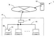
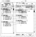
以下、本発明を実施するための形態を図面を用いて説明する。図1は、本発明の稼働状況表示プログラムを動作させるコンピュータ(サーバ10)を含む稼働状況表示システム1の全体構成を示しており、図2は、稼働状況表示システム1のサーバ10の機能を示すブロック図である。なお、本発明の稼働状況表示プログラムは、複数の利用者の稼働状況(人の稼働状況)を、適切に把握して可視化するプログラムである。[Overall configuration of the operation status display system 1 (FIG. 1) and functions of the server 10 (FIG. 2)]
Hereinafter, an embodiment of the present invention will be described with reference to the drawings. Fig. 1 shows the overall configuration of an operation
本発明の稼働状況表示プログラムは、サーバ10(コンピュータに相当)にインストールされており、サーバ10の動作を制御する。なお端末装置50は、一般的なブラウザ(閲覧ソフト)を有していればよく、当該ブラウザを介して表示画面での入出力や、サーバ10との送受信を行う。The operating status display program of the present invention is installed in the server 10 (corresponding to a computer) and controls the operation of the
図1に示すように、稼働状況表示システム1は、通信回線Nに接続されたサーバ10(コンピュータに相当)と、通信関連機器40を介して通信回線Nに接続された複数の端末装置50等にて構成されている。As shown in FIG. 1, the operation
例えば端末装置50は、企業α内のパーソナルコンピュータであり、表示装置51を有しており、通信回線41(有線LAN、無線LAN)にて通信関連機器40に接続されている。また通信関連機器40は、終端装置、ルータ、ファイヤウォール等である。企業αの利用者(この場合、従業員)は、自身に割り当てられた端末装置50を用いて、以降に説明するように端末装置50を用いて入力等を行い、端末装置50の表示装置51に種々の画面等を表示させる。また通信回線Nは例えばインターネットであり、本発明の稼働状況表示プログラムは、インターネット上のサーバ10にていわゆるクラウドサービスを提供するプログラムである。なお、サーバ10を通信回線Nに接続するのでなく、通信回線41に接続して、企業α内でサービスを提供するようにしてもよい。For example, the
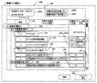
図2に示すように、サーバ10は記憶装置12を有しており、サーバ10の機能としては、ログイン支援手段11A、スケジュール作成支援手段11B、実績入力支援手段11C、稼働状況算出手段11D、稼働状況表示手段11E等を有している。なお、利用者が画面を確認する表示装置は、端末装置50の表示装置である。以下、第1の実施の形態、及び第2の実施の形態について説明する。第1の実施の形態は、図18に示すように、稼働状況表示画面として、利用者ID(すなわち利用者)に対応付けた主アイコンG52のみを一覧状に表示するものである。第2の実施の形態は、図27に示すように、稼働状況表示画面として、利用者ID(すなわち利用者)に対応付けた主アイコンG52と補助アイコンG53(主アイコンに隣接する小型のアイコン)を一覧状に表示するものである。As shown in FIG. 2, the
なお以下の説明では、利用者は企業αの従業員とする。また企業αは、始業時刻(期間開始時刻に相当)が8:00、休憩時刻が12:00~13:00、終業時刻(期間終了時刻に相当)が17:00、の勤務時間が8時間であるものとする。また第1の実施の形態では、図6の登録ユーザ情報J10における利用者ID:B001の利用者の例を説明する。In the following explanation, the user is assumed to be an employee of company α. Furthermore, company α has an eight-hour work day, with a start time (corresponding to the start time of the period) of 8:00, a break time from 12:00 to 13:00, and an end time (corresponding to the end time of the period) of 17:00. In the first embodiment, an example of a user with user ID: B001 in the registered user information J10 in Figure 6 will be explained.
利用者ID:B001の利用者は、始業時刻前に出勤し、端末装置50を操作して、サーバ10にログインし、本日分(特定された1日、所定期間に相当)の自身の作業予定であるスケジュール情報J40(図12参照)を作成する。そして当該利用者は、勤務時間内にスケジュール情報の各作業予定項目の作業を進め、実績を入力していく。サーバは、始業時刻からの経過時間に応じて、作業予定項目と実績に基づいて稼働状況(稼働率)を算出し、可視化した稼働状況表示画面G50(図18参照)を利用者の端末装置に表示させる。以下、第1の実施の形態における、ログイン、スケジュール作成、実績入力、稼働状況の算出、稼働状況の表示について順に説明する。A user with user ID: B001 arrives at work before the start of work, operates
●[第1の実施の形態(図3~図18)]
●[ログイン支援処理(図3~図6)と、ログイン支援処理にて更新されたアイコン情報の例(図7)]
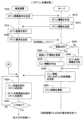
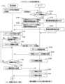
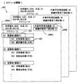
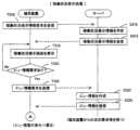
図3は、図2に示すログイン支援手段11Aとしてのサーバ10の処理を説明するための、サーバ10及び端末装置50の処理手順を説明するフローチャートである。利用者ID:B001の利用者は、出社すると、自身の端末装置50を起動してサーバ10にアクセスし、ログイン要求の操作を行う。[First embodiment (FIGS. 3 to 18)]
[Login support process (Figures 3 to 6) and an example of icon information updated by the login support process (Figure 7)]
Fig. 3 is a flowchart illustrating the processing procedure of the
ステップT010にて端末装置50は、利用者がログイン情報要求を入力すると、ログイン情報要求をサーバ10に送信し、サーバ10からのログイン情報を待つ。In step T010, when the user inputs a login information request, the
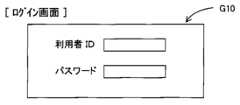
ステップS010にてサーバ10は、ログイン情報要求を受信すると、ログイン情報を作成し、ステップS015へ処理を進める。なおログイン情報は、図4に示すログイン画面G10を端末装置50の表示装置51に表示させるための情報である。When the
ステップS015にてサーバ10は、作成したログイン情報を端末装置50に送信し、端末装置50からのログイン要求を待つ。In step S015, the
ステップT015にて端末装置50は、サーバ10からログイン情報を受信すると、ログイン画面G10(図4)を表示装置に表示し、利用者からの利用者IDの入力と、パスワードの入力を待つ。利用者IDは、利用者ごとに割付けられた識別情報であり、パスワードは、利用者IDごとに設定されている。When the
記憶装置12には、図6に示す登録ユーザ情報J10が予め記憶されている。登録ユーザ情報J10には、利用者ID、パスワード、最終ログイン日時、ログイン状態、氏名、部署等、利用者に関する情報が記憶されている。なお、「最終ログイン日時」には、対象の利用者が最後にログインした日時が記憶されており、「ログイン状態」には、対象の利用者が現在ログインしているか否かを示す情報が記憶されている。Registered user information J10 shown in FIG. 6 is prestored in the
ステップT020にて端末装置50は、ログイン画面G10(図4)に、利用者から利用者IDとパスワードが入力されると、入力された利用者IDとパスワードを含むログイン要求をサーバ10に送信し、サーバ10からのメニュー情報を待つ。In step T020, when the user inputs a user ID and password on the login screen G10 (Figure 4), the
ステップS020にてサーバ10は、端末装置から利用者ID及びパスワードを含むログイン要求を受信すると、ログイン要求に含まれている利用者ID及びパスワードと、登録ユーザ情報J10(図6参照)に記憶されている利用者ID及びパスワードと、を認証(照合)し、認証が成功か否かを判定する。サーバ10は、認証が成功した場合(Yes)はステップS025へ処理を進め、認証が成功しなかった場合(No)はステップS040へ処理を進める。In step S020, when the
ステップS025へ処理を進めた場合、サーバ10は、登録ユーザ情報J10(図6)を更新し、ステップS030へ処理を進める。なお、登録ユーザ情報J10の更新個所は、この場合、「最終ログイン日時」と「ログイン状態」である。If the process proceeds to step S025, the
ステップS030にてサーバ10は、メニュー情報を作成してステップS050へ処理を進める。なおメニュー情報は、図5に示すメニュー画面G20を端末装置50の表示装置に表示させるための情報である。In step S030, the
ステップS040へ処理を進めた場合、サーバ10は、ログイン失敗情報を作成してステップS050へ処理を進める。なおログイン失敗情報の表示画面については図示省略する。If the process proceeds to step S040, the
ステップS050へ処理を進めた場合、サーバ10は、作成したメニュー情報(認証成功の時)またはログイン失敗情報(認証失敗の時)を端末装置50に送信し、ステップS060へ処理を進める。If the process proceeds to step S050, the
ステップS060にてサーバ10は、図7に示すアイコン情報J20を更新し、端末装置50からの次の要求等を待つ。なお、図7に示すアイコン情報J20は、始業時刻よりも前(例えば時刻4:00等)に、サーバ10が事前に作成しており、作成時において「利用者ID」と「部署」は、登録ユーザ情報J10(図6)から転記されている。ステップS060でのアイコン情報J20の更新個所は、図7に符号J23にて示す「ログイン状態」である。利用者ID:B001が、端末装置50を用いて上記の処理にてログインすると、図7に示すように、利用者ID:B001の「ログイン状態」には「ログイン」が記憶される。なお図7に示すアイコン情報J20の例は、始業時刻8:00におけるアイコン情報の例を示している。またログインしていない利用者IDに対応する「ログイン状態」には、「ログアウト」が記憶される。In step S060, the
なお図7に示すアイコン情報J20には、例として符号J21の位置には、現在日時(図7の例では、2021年1月27日8:00)が記憶され、符号J22の位置には、始業時刻や終業時刻や勤務時間などが記憶されている。In the icon information J20 shown in FIG. 7, for example, the current date and time (8:00 on January 27, 2021 in the example of FIG. 7) is stored at the position of symbol J21, and the start time, end time, working hours, etc. are stored at the position of symbol J22.
ステップT025にて端末装置50は、メニュー情報を受信すると、メニュー画面G20(図5参照)を表示装置に表示し、利用者からの入力を待つ。なお、ログイン失敗情報を受信した場合のログイン失敗画面の例については説明を省略する。なおステップT025への符号Aは、後述する「スケジュール作成支援処理」、「実績入力支援処理」、「稼働状況表示処理」にて、利用者が「メニューに戻る」を入力(選択)した場合に処理が戻る位置を示している。When the
ステップT030にて端末装置50は、メニュー画面G20に、利用者からの入力が有るか否かを判定する。端末装置50は、利用者からの入力が有った場合(Yes)はメニュー画面G20(図5参照)の各入力の処理を実施する。端末装置50は、メニュー画面G20にて「スケジュール作成」が入力(選択)された場合は後述する「スケジュール作成支援処理」へ処理を進め、「実績入力」が入力(選択)された場合は後述する「実績入力支援処理」へ処理を進め、「稼働状況を表示」が入力(選択)された場合は後述する「稼働状況表示処理」へ処理を進める。In step T030, the
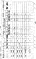
●[アイコン情報J20の構成(図7)]
アイコン情報J20は、サーバ10が、図18の例に示す稼働状況表示画面G50を作成する際に利用する情報である。アイコン情報J20は、上述したように、サーバ10が、例えば始業時刻よりも充分前の4:00に作成する。作成時のアイコン情報J20には、利用者ID、部署が登録ユーザ情報J10(図6参照)からコピーされており、他の欄は空白状態である。また図7のアイコン情報J20は、始業時刻である8:00の例を示しており、ログイン状態J23に、各利用者のログイン状態が記憶されている。また図7のアイコン情報J20には、出張/休業J24、スケジュール情報の登録有無J25、作業予定項目総数J26、各時刻までの目標と実績J26X、稼働率J27、測定値評価結果J28などが空白状態(未入力状態)であるが、これらについては後述する。[Configuration of Icon Information J20 (FIG. 7)]
The icon information J20 is information used when the
●[メニュー画面G20から「出張」を入力(選択)した場合]
また、例えば利用者ID:B002の利用者が、その日は出張の場合や、社内で進める作業が無くスケジュールを作成できない場合では、図5に示すメニュー画面G20から「出張」を入力(選択)する。図5に示すメニュー画面G20から「出張」が入力(選択)された場合、端末装置50は、利用者IDを含む出張情報をサーバ10に送信する。サーバ10は、出張情報を受信すると、図13のアイコン情報J20に示すように、利用者ID:B002に対応する出張/休業J24に「出張」を記憶する。● [When you enter (select) "Business trip" from the menu screen G20]
For example, if a user with user ID: B002 is on a business trip that day, or if there is no work to be done in the company and a schedule cannot be created, the user inputs (selects) "business trip" from the menu screen G20 shown in Fig. 5. When "business trip" is input (selected) from the menu screen G20 shown in Fig. 5, the
また利用者ID:B002の利用者が、すでに「出張」を入力したが、「出張」が取りやめになった場合、図5に示すメニュー画面G20から「出張をキャンセル」を入力する。この場合、アイコン情報J20(図13参照)の利用者ID:B002の出張/休業J24に記憶されていた「出張」が削除される。In addition, if the user with user ID: B002 has already entered "business trip" but the "business trip" is canceled, the user enters "Cancel business trip" from the menu screen G20 shown in FIG. 5. In this case, the "business trip" stored in the business trip/absence J24 for user ID: B002 in the icon information J20 (see FIG. 13) is deleted.
●[メニュー画面G20から「ログアウト」が入力(選択)された場合]
例えば利用者ID:B002の利用者が、図5に示すメニュー画面G20から「ログアウト」を入力(選択)した場合、端末装置50は、利用者IDを含むログアウト要求をサーバ10に送信する。サーバ10は、ログアウト要求を受信すると、図13のアイコン情報J20に示すように、利用者ID:B002に対応するログイン状態J23に「ログアウト」を記憶する。[When "Logout" is entered (selected) on the menu screen G20]
For example, when a user with user ID: B002 inputs (selects) "Logout" from the menu screen G20 shown in Fig. 5, the
サーバ10を動作させる稼働状況表示プログラムは、上記の「ログイン支援処理」に説明したように、サーバ10(コンピュータ)を、ログイン支援手段11A(図2参照)として機能させる。The operation status display program that runs the
●[スケジュール作成支援処理(図8~図12)と、スケジュール作成支援処理にて更新されたアイコン情報の例(図13)]
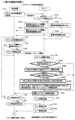
次に、図5に示すメニュー画面G20から「スケジュール作成」が入力(選択)された場合の処理である「スケジュール作成支援処理」について説明する。利用者ID:B001の利用者が、図5に示すメニュー画面G20から「スケジュール作成」を入力(選択)すると、端末装置50は、図8に示すステップT110へ処理を進める。[Schedule creation support process (FIGS. 8 to 12) and an example of icon information updated in the schedule creation support process (FIG. 13)]
Next, a description will be given of a "schedule creation support process" which is a process performed when "schedule creation" is input (selected) from the menu screen G20 shown in Fig. 5. When a user with user ID: B001 inputs (selects) "schedule creation" from the menu screen G20 shown in Fig. 5, the
ステップT110にて端末装置50は、利用者IDを含むスケジュール作成支援要求をサーバ10に送信し、サーバ10からの応答を待つ。In step T110, the
ステップS110にてサーバ10は、スケジュール作成支援要求を受信すると、受信したスケジュール作成支援要求に含まれている利用者IDに対応する本日分のスケジュール情報が記憶装置12に記憶されているか否かを判定する。サーバ10は、利用者IDに対応する本日分のスケジュール情報がすでに記憶装置12に記憶されている場合(Yes)はステップS120へ処理を進め、記憶されていない場合(No)はステップS130へ処理を進める。In step S110, when the
ステップS120へ処理を進めた場合、サーバ10は、記憶装置12から利用者IDに対応する本日分のスケジュール情報J40(図12参照)と、業務候補情報J30(図10参照)を読み出し、ステップS125へ処理を進める。なおスケジュール情報J40と業務候補情報J30の詳細については後述する。If the process proceeds to step S120, the
スケジュール情報J40(図12参照)は、利用者IDに対応する利用者が、出社時に、その日に行う予定の業務として作成する情報である。また業務候補情報J30(図10参照)は、スケジュール情報J40(図12参照)の作成を容易にするため、予め複数の業務が登録されている。利用者は、業務候補情報J30(図10参照)の中から所望する業務を選択して自身のスケジュール情報J40(図12参照)を作成して記憶装置12に記憶する。なお、スケジュール作成画面G30(図9)を用いたスケジュール情報の作成手順等については後述する。Schedule information J40 (see FIG. 12) is information that a user corresponding to a user ID creates when arriving at work as the tasks that the user plans to perform that day. In addition, in order to facilitate the creation of schedule information J40 (see FIG. 12), multiple tasks are preregistered in the task candidate information J30 (see FIG. 10). The user selects the desired task from the task candidate information J30 (see FIG. 10), creates his/her own schedule information J40 (see FIG. 12), and stores it in the
ステップS125へ処理を進めた場合、サーバ10は、記憶装置12から読み出したスケジュール情報J40(図12参照)と業務候補情報J30(図10参照)を端末装置50に送信し、端末装置50からの次の要求等を待つ。If the process proceeds to step S125, the
ステップS130へ処理を進めた場合、サーバ10は、記憶装置12から業務候補情報J30(図10参照)を読み出し、ステップS135へ処理を進める。If processing proceeds to step S130, the
ステップS135に処理を進めた場合、サーバ10は、記憶装置12から読み出した業務候補情報J30(図10参照)を端末装置50に送信し、端末装置50からの次の要求等を待つ。If the process proceeds to step S135, the
ステップT115にて端末装置50は、スケジュール情報J40(図12参照)と業務候補情報J30(図10参照)(または業務候補情報J30)を受信すると、図9の例に示すスケジュール作成画面G30を表示装置に表示し、ステップT120へ処理を進める。In step T115, when the
図9に示すように、例えばスケジュール作成画面G30には、左側に業務候補情報J30(図10参照)が表示され、右側にはスケジュール情報J40(図12参照)が表示される。なお、スケジュール情報J40を受信しなかった場合、利用者ID:B001の利用者がスケジュール作成画面G30の「新規作成」を入力(選択)すると、白紙状態の(何もスケジュールが入っていない)スケジュール情報J40が右側に作成される。すでに本日分のスケジュール情報J40を作成して記憶装置12に記憶させていた場合、スケジュール情報J40が自動的に読み出され、利用者は業務の追加や削除等を行うことができる。As shown in FIG. 9, for example, the schedule creation screen G30 displays task candidate information J30 (see FIG. 10) on the left side and schedule information J40 (see FIG. 12) on the right side. If schedule information J40 is not received, when a user with user ID: B001 inputs (selects) "Create new" on the schedule creation screen G30, blank schedule information J40 (with no schedule) is created on the right side. If schedule information J40 for today has already been created and stored in the
ステップT120にて端末装置50は、スケジュール情報の更新要求が入力されたか否かを判定する。端末装置50は、図9に示すスケジュール作成画面G30の中の「更新」が入力(選択)された場合(Yes)はステップT125へ処理を進め、「更新」が入力されていない場合(No)はステップT130へ処理を進める。In step T120, the
ステップT125へ処理を進めた場合、端末装置50は、図9に示すスケジュール作成画面G30の右側に表示されているスケジュール情報J40(利用者が新規作成または更新したスケジュール情報)をサーバ10に送信し、ステップT130へ処理を進める。なお、送信されたスケジュール情報J40には、図12の符号J40Aに示すように、利用者ID(この例では、利用者ID:B001)と日付が含まれている。スケジュール情報J40(図12参照)は、利用者IDごと、かつ日付ごとに作成され、記憶装置12には、本日分のスケジュール情報だけでなく、過去のスケジュール情報も記憶されている。If the process proceeds to step T125, the
ステップS140にてサーバ10は、スケジュール情報を受信すると、受信したスケジュール情報を記憶装置12に記憶(更新)し、ステップS145へ処理を進める。サーバ10は、対象の利用者IDの本日分のスケジュール情報がすでに記憶装置12に記憶されている場合、対象の利用者IDの本日分のスケジュール情報を上書きして記憶する。またサーバ10は、対象の利用者IDのスケジュール情報が記憶装置12に記憶されていない場合、対象の利用者IDの本日分のスケジュール情報として新規に記憶する。またサーバ10は、スケジュール情報の更新の際、受信したスケジュール情報J40(図9参照)の作業予定項目総数J40Bの値を算出して記憶し、スケジュール情報J40を更新する。In step S140, when the
ステップS145にてサーバ10は、更新したスケジュール情報(作業予定項目総数J40B(図9参照)を更新したスケジュール情報)を端末装置50に送信し、ステップS150へ処理を進める。In step S145, the
ステップS150にてサーバ10は、図13に示すようにアイコン情報J20を更新し、端末装置50からの次の要求等を待つ。図13に示すアイコン情報J20は、始業時刻8:00の時点の図7のアイコン情報J20に対して、始業時刻8:00から50分経過後の8:50の状態の例を示しており、各利用者IDの利用者からのスケジュール情報J40(図12参照)の記憶がなされた状態の例を示している。In step S150, the
図13に示すアイコン情報J20において、サーバ10は、ステップS150のアイコン情報の更新にて、アイコン情報J20のスケジュールの登録有無J25に、本日分のスケジュール情報を記憶した利用者IDに対応する位置に「有り」を記憶する。なおアイコン情報J20の更新の詳細については後述する。In the icon information J20 shown in FIG. 13, the
ステップT130へ処理を進めた場合、端末装置50は、メニュー情報要求が入力されたか否かを判定する。端末装置50は、図9に示すスケジュール作成画面G30の中の「メニューに戻る」が入力(選択)された場合(Yes)はステップT135へ処理を進め、「メニューに戻る」が入力(選択)されていない場合(No)はステップT115へ処理を戻す。If the process proceeds to step T130, the
ステップT135へ処理を進めた場合、端末装置50は、メニュー情報要求をサーバ10に送信し、サーバ10からのメニュー情報を待つ。なおメニュー情報は、図5に示すメニュー画面G20を端末装置50の表示装置に表示させるための情報である。そして端末装置50は、サーバ10からメニュー情報を受信すると、図3に示すフローチャートの符号Aの位置に戻り、ステップT025の処理にてメニュー画面G20(図5参照)を表示して利用者からの入力を待つ。If the process proceeds to step T135, the
ステップS155にてサーバ10は、メニュー情報要求を受信すると、メニュー情報を作成してステップS160へ処理を進める。When the
ステップS160にてサーバ10は、作成したメニュー情報を端末装置50に送信し、端末装置50からの次の要求等を待つ。In step S160, the
●[業務候補情報J30の全体構成(図10)と詳細(図11)]
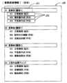
図10は、業務候補情報J30の全体構成の例を示しており、業務候補情報J30には、各利用者が自身のスケジュールとしての各業務を選択できるように、想定された種々の業務J32が登録されている。業務J32(候補業務)は、予め設定された業務グループ名称J31ごとに分類されている。図10の例では、「01営業部[顧客X]」、「02営業部[顧客Y]」、「03営業部[顧客Z]」、「04工程内品質チェック」というそれぞれの業務グループ名称J31ごとに業務J32(候補業務)が分類されている。[Overall configuration of job candidate information J30 (FIG. 10) and details (FIG. 11)]
10 shows an example of the overall configuration of the job candidate information J30, in which various assumed jobs J32 are registered so that each user can select each job for his/her own schedule. The jobs J32 (candidate jobs) are classified according to a preset job group name J31. In the example of FIG. 10, the jobs J32 (candidate jobs) are classified according to each job group name J31, such as "01 Sales Department [Customer X]", "02 Sales Department [Customer Y]", "03 Sales Department [Customer Z]", and "04 In-process quality check".
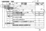
また図11は、図10に示す業務グループ名称J31=「01営業部[顧客X]」、業務J32=「001日常業務(毎日)」、の詳細の例を示している。図11に示すように、業務J32には、単数または複数の作業予定項目J34、作業予定項目J34の作業タイトルJ33、作業予定項目J34に対応させた実績入力部J35、が設定されている。図11に示すように、作業予定項目J34には、業務J32及び作業タイトルJ33に対応させた具体的な作業内容が示されている。Figure 11 also shows an example of details of the task group name J31 = "01 Sales Department [Customer X]" and task J32 = "001 Daily Tasks (Every Day)" shown in Figure 10. As shown in Figure 11, task J32 has one or more scheduled work items J34, task titles J33 for the scheduled work items J34, and a performance input section J35 corresponding to the scheduled work items J34 set. As shown in Figure 11, the scheduled work items J34 show specific work contents corresponding to the task J32 and task title J33.
また図11の例では、実績入力部J35には、作業済入力部J36と、チェック者日時記録部J37と、が設定されている。作業済入力部J36は、作業予定項目J34の作業内容を実施したことを示す作業済情報(完了譲歩)の入力(利用者からの入力)を受け付ける入力部である。また作業タイトルJ33の「一括チェック」に作業済情報を入力すると、対応する作業済入力部J36にそれぞれ適切な情報が自動的に入力される。図11の例では、利用者が、作業タイトルJ33の「ラベル出力」の「一括チェック」に入力すると、対応する作業予定項目J34である「1ラベル印刷内容を確認」、「2パソコンにてラベルを出力」のそれぞれに対応する作業済入力部J36に、作業済情報(完了情報)が自動的に入力される。In the example of FIG. 11, the performance input section J35 is configured with a work done input section J36 and a checker date and time recording section J37. The work done input section J36 is an input section that accepts input (input from the user) of work done information (completion concession) indicating that the work content of the planned work item J34 has been completed. When work done information is input into the "Bulk check" of the work title J33, appropriate information is automatically input into the corresponding work done input section J36. In the example of FIG. 11, when the user inputs into the "Bulk check" of the work title J33 "Label output", work done information (completion information) is automatically input into the work done input section J36 corresponding to each of the corresponding planned work items J34, "1 Check label print contents" and "2 Output labels on PC".
またチェック者日時記録部J37は、作業済入力部J36に作業済情報が入力された際に、入力した利用者の利用者ID(または氏名)と日時を、サーバ10が自動的に入力する記録部である。なお、サーバ10によるチェック者日時記録部J37への入力の詳細については、後述する実績入力の説明に記載する。The checker date and time recording unit J37 is a recording unit into which the
●[スケジュール作成画面G30(図9)とスケジュール情報J40(図9、図12)]
図9に示すように、端末装置50の表示装置に表示されるスケジュール作成画面G30は、左側に業務候補情報J30、右側にスケジュール情報J40が表示される。サーバ10の記憶装置に本日分のスケジュール情報J40がすでに記憶されている場合は、記憶されているスケジュール情報J40が読み出されて表示される。本日分のスケジュール情報J40を新規作成する場合は、利用者が「新規作成」を入力することで、白紙状態のスケジュール情報から作成することができる。[Schedule creation screen G30 (FIG. 9) and schedule information J40 (FIG. 9, FIG. 12)]
9, the schedule creation screen G30 displayed on the display device of the
利用者は、左側に表示された業務候補情報J30の中から、自身が本日作業を予定する業務J32をダブルクリックしたり、ドラッグして右側のスケジュール情報J40にコピーさせたりすることで、右側に表示されている自身の本日分のスケジュール情報J40を作成することができる。作成が終了した場合、利用者は、スケジュール作成画面G30の「更新」を入力(選択)することで、作成したスケジュール情報J40をサーバ10の記憶装置12に記憶させることができる。The user can create their own schedule information J40 for today, which is displayed on the right side, by double-clicking or dragging the task J32 that they plan to work on today from the task candidate information J30 displayed on the left side and copying it to the schedule information J40 on the right side. When creation is complete, the user can store the created schedule information J40 in the
なお、業務候補情報J30には、すべての利用者が業務J32を選択できるように非常に多数の業務J32が登録されている。従って、すべての業務J32を表示させて、その中から必要な業務J32を選択するのは非常に手間がかかる。そこで、スケジュール作成画面G30には、図9に示す符号G31にて示す個所に、部署と利用者IDを入力して「検索」を入力することで、左側に表示される業務候補情報J30の数を自動的に絞る仕組みが施されている。In addition, a large number of tasks J32 are registered in the task candidate information J30 so that all users can select a task J32. Therefore, it is very time-consuming to display all tasks J32 and select the required task J32 from among them. Therefore, the schedule creation screen G30 has a mechanism that automatically narrows down the number of task candidate information J30 displayed on the left side by entering the department and user ID in the area indicated by symbol G31 in FIG. 9 and then selecting "search."
また作成されたスケジュール情報J40(図9、図12参照)は、図9のスケジュール作成画面G30に示すように、業務候補情報J30に表示されているとおりのものがコピーされる。つまり、図11に示す詳細も、そのままコピーされる。The created schedule information J40 (see Figures 9 and 12) is a copy of what is displayed in the job candidate information J30, as shown in the schedule creation screen G30 in Figure 9. In other words, the details shown in Figure 11 are also copied as is.
上述したように、サーバ10を動作させる稼働状況表示プログラムは、記憶装置に記憶されている業務候補情報に基づいた複数の業務である候補業務を端末装置の表示装置に表示させ、表示された候補業務の中から選択された業務を、スケジュール情報として記憶装置に記憶させる。As described above, the operation status display program that operates the
●[利用者の操作と、ステップS150でのアイコン情報J20(図13)の更新]
例えば利用者ID:B001の利用者は、8:00にログインして、図5に示すメニュー画面G20にて「スケジュール作成」を入力すると、図9の例に示すスケジュール作成画面G30が端末装置50に表示される。なお、本日の最初の「スケジュール作成」の場合、利用者はスケジュール作成画面G30の「新規作成」を入力することで、本日分のスケジュール情報を作成することができる。[User Operation and Update of Icon Information J20 (FIG. 13) in Step S150]
For example, when a user with user ID: B001 logs in at 8:00 and inputs "Create Schedule" on the menu screen G20 shown in Fig. 5, the schedule creation screen G30 shown in the example of Fig. 9 is displayed on the
利用者がスケジュール作成画面G30(図9参照)にて作成中は、スケジュール作成画面G30の作業予定項目総数J40Bの値は更新されない。利用者が、スケジュール作成画面G30の「更新」を入力すると、図8に示すステップT125にてスケジュール情報がサーバ10に送信される。そしてサーバ10が、ステップT140にてスケジュール情報J40(図12参照)に含まれている作業予定項目の数を計算し、作業予定項目総数J40Bの値を更新してスケジュール情報J40を更新し、更新したスケジュール情報J40をステップS145にて端末装置50に送信する。更新したスケジュール情報を受信した端末装置50のスケジュール作成画面G30(図9参照)では、作業予定項目総数J40Bは更新された値が表示される。While the user is creating a schedule on the schedule creation screen G30 (see FIG. 9), the value of the total number of scheduled work items J40B on the schedule creation screen G30 is not updated. When the user inputs "Update" on the schedule creation screen G30, the schedule information is sent to the
作業予定項目総数J40Bには、そのスケジュール情報に記憶されている業務の中の各作業予定項目J34(図11参照)の総数が、サーバ10によって計算されて記憶される。作業予定項目総数J40Bは、スケジュール情報に含まれている作業予定項目J34(図11参照)の総数であり、実績入力部J35へ実績情報を入力するべき作業予定項目J34の総数である。また実績作業完了項目数J40Cには、そのスケジュール情報J40の中に記憶されている実績情報の総数である。なお実績情報の入力については、後述する「実績入力支援処理」にて詳細を説明する。図9及び図12に示すスケジュール情報J40は、スケジュール情報J40を作成した時点の状態を示しているので、実績作業完了項目数には0(ゼロ)が記憶されている。The total number of scheduled work items J40B is calculated by the
図8に示すステップS150のアイコン情報の更新では、この作業予定項目総数J40Bの値が、図13に示すようにアイコン情報J20の作業予定項目総数J26に反映される。例えば図9及び図12に示すように、利用者ID:B001に対応するスケジュール情報J40の作業予定項目総数J40Bが「24」である場合、サーバ10は、図13に示すアイコン情報J20における作業予定項目総数J26の利用者ID:B001に対応する個所に「24」を記憶する。When updating the icon information in step S150 shown in FIG. 8, this value of the total number of scheduled work items J40B is reflected in the total number of scheduled work items J26 of the icon information J20 as shown in FIG. 13. For example, as shown in FIG. 9 and FIG. 12, if the total number of scheduled work items J40B of the schedule information J40 corresponding to user ID: B001 is "24," the
また図13に示すように、アイコン情報J20には、各時刻までの目標と実績J26Xが設定されている。この例では、始業時刻8:00、休憩12:00~13:00、終業時刻17:00、勤務時間:8時間、に基づいて、始業時刻からの経過時間が1時間である「9:00」、経過時間が2時間である「10:00」~経過時間が7時間(休憩を除く)である「16:00」、経過時間が8時間(休憩を除く)である「17:00」、のそれぞれの時刻に対して、目標作業完了項目数J26Yと実績作業完了項目数J26Zが設定されている。As shown in FIG. 13, the icon information J20 has targets and results J26X set up to each time. In this example, based on a work start time of 8:00, a break from 12:00 to 13:00, an end time of 17:00, and eight hours of work, the target number of completed work items J26Y and the actual number of completed work items J26Z are set for each of the following times: "9:00", which is one hour after the work start time; "10:00", which is two hours after the work start time, "16:00", which is seven hours after the work start time (excluding breaks); and "17:00", which is eight hours after the work start time (excluding breaks).
次に、図13の例に示すアイコン情報J20において、サーバ10が、利用者ID:B001に対応する各目標作業完了項目J26Yに、各数値を算出して記憶する手順について説明する。例えばサーバ10は、利用者ID:B001に対応する本日分のスケジュール情報J40(図9、図12参照)を記憶(更新)すると、記憶したスケジュール情報J40に含まれている作業予定項目総数J40Bの数値(この場合、「24」)を、図13に示すアイコン情報J20における利用者ID:B001に対応する作業予定項目総数J26に「24」を記憶する。次にサーバ10は、各時刻までの目標と実績J26Xの各時刻までに、どれだけの作業予定項目を終了させるべきか、を算出する。作業予定項目総数J26が「24」の場合、勤務時間が8時間であるので、サーバ10は、1時間ごとに「3」ずつ増加する3、6、9・・21、24を算出し、9:00(1時間経過)に対応する目標作業完了項目数J26Aには「3(=24*1/8)」を記憶し、10:00(2時間経過)に対応する目標作業完了項目数J26Bには「6(=24*2/8)」を記憶する。同様にサーバ10は、16:00(7時間経過)に対応する目標作業完了項目数J26Cには「21(=24*7/8)」を記憶し、17:00(8時間経過)に対応する目標作業完了項目数J26Dには「24(=24*8/8)」を記憶する。Next, the procedure for the
サーバ10を動作させる稼働状況表示プログラムは、上記の「スケジュール作成支援処理」に説明したように、サーバ10(コンピュータ)を、それぞれの利用者が、所定期間(この場合、本日)内に行う予定の業務であって当該業務の作業内容である単数または複数の作業予定項目を含むとともに利用者IDに対応付けて入力された業務を、利用者IDごとのスケジュール情報として記憶装置に記憶させる、スケジュール作成支援手段11B(図2参照)として機能させる。The operation status display program that operates the
●[実績入力支援処理(図14、図15)と、実績入力支援処理にて更新されたアイコン情報の例(図16)]
次に、図5に示すメニュー画面G20から「実績入力」が入力(選択)された場合の処理である「実績入力支援処理」について説明する。利用者ID:B001の利用者が、図5に示すメニュー画面G20から「実績入力」を入力(選択)すると、端末装置50は、図14に示すステップT210へ処理を進める。[Results input support process (FIGS. 14 and 15) and an example of icon information updated by the results input support process (FIG. 16)]
Next, a description will be given of the "achievement input support process" which is a process performed when "achievement input" is input (selected) from the menu screen G20 shown in Fig. 5. When the user with user ID: B001 inputs (selects) "achievement input" from the menu screen G20 shown in Fig. 5, the
ステップT210にて端末装置50は、利用者IDを含む実績入力支援要求をサーバ10に送信し、サーバ10からの応答を待つ。In step T210, the
ステップS210にてサーバ10は、実績入力支援要求を受信すると、受信した実績入力支援要求に含まれている利用者IDに対応する本日分のスケジュール情報が記憶装置12に記憶されているか否かを判定する。サーバ10は、利用者IDに対応する本日分のスケジュール情報がすでに記憶装置12に記憶されている場合(Yes)はステップS220へ処理を進め、記憶されていない場合(No)はステップS230へ処理を進める。In step S210, when the
ステップS220へ処理を進めた場合、サーバ10は、記憶装置12から利用者IDに対応する本日分のスケジュール情報J40(図12参照)を読み出し、ステップS225へ処理を進める。If the process proceeds to step S220, the
ステップS225へ処理を進めた場合、サーバ10は、記憶装置12から読み出したスケジュール情報J40(図12参照)を端末装置50に送信し、端末装置50からの次の要求等を待つ。If the process proceeds to step S225, the
ステップS230へ処理を進めた場合、サーバ10は、実績を入力するべき本日分のスケジュール情報が無いため、エラー情報(エラー画面(図示省略)を端末装置に表示させるための情報であり、「本日分のスケジュール情報がありません」等を含む情報)を作成し、ステップS235へ処理を進める。なお、エラー画面の図示は省略する。If the process proceeds to step S230, the
ステップS235に処理を進めた場合、サーバ10は、作成したエラー情報を端末装置50に送信し、端末装置50からの次の要求等を待つ。If the process proceeds to step S235, the
ステップT215にて端末装置50は、スケジュール情報J40(図12参照)を受信すると、図15の例に示す実績入力画面G40を表示装置に表示し、ステップT220へ処理を進める。When the
図15に示す実績入力画面G40の例は、利用者ID:B001の利用者の実績入力画面の例を示している。当該利用者は、上述したスケジュール作成支援処理にて作成してサーバ10に登録(記憶装置12に記憶)させた、自身の本日分のスケジュール情報J40を実績入力支援処理にて読み出して、作業が完了した旨を示す完了情報を入力していく。なお、エラー情報を受信した場合の画面及び処理については説明を省略する(エラー画面からメニュー画面に戻ることができる)。当該利用者は、自身の本日分のスケジュール情報J40(図15参照)に記憶されている作業予定項目J44(図15参照)に沿った作業を実施し、作業が完了した作業予定項目J44に対応する実績入力部J45(作業済入力部J46)に完了情報(作業を実施したことを示す作業済情報であり、この例では「V」印)を入力していく。なお、完了情報の入力手順等の詳細については後述する。The example of the performance input screen G40 shown in FIG. 15 shows an example of the performance input screen of a user with user ID: B001. The user reads out the schedule information J40 for today, which was created in the schedule creation support process described above and registered in the server 10 (stored in the storage device 12), in the performance input support process, and inputs completion information indicating that the work has been completed. Note that the screen and processing when error information is received will not be described (the user can return to the menu screen from the error screen). The user performs work according to the scheduled work items J44 (see FIG. 15) stored in the user's schedule information J40 for today (see FIG. 15), and inputs completion information (work completed information indicating that the work has been performed, in this example, a "V" mark) in the performance input section J45 (work completed input section J46) corresponding to the scheduled work items J44 for which the work has been completed. Note that the details of the procedure for inputting completion information will be described later.
ステップT220にて端末装置50は、完了情報の記憶要求が入力されたか否かを判定する。端末装置50は、図15に示す実績入力画面G40の中の「確認」が入力(選択)された場合(Yes)はステップT225へ処理を進め、「確認」が入力されていない場合(No)はステップT230へ処理を進める。In step T220, the
ステップT225へ処理を進めた場合、端末装置50は、図15に示す実績入力画面G40のスケジュール情報J40(完了情報が入力されたスケジュール情報J40)をサーバ10に送信し、ステップT230へ処理を進める。If the process proceeds to step T225, the
ステップS240にてサーバ10は、スケジュール情報を受信すると、受信したスケジュール情報を記憶装置12に記憶(上書き更新)し、ステップS245へ処理を進める。つまり、サーバ10は、作業済入力部J46(図15参照)に作業済情報(チェック印(V))が入力されると、作業済情報を完了情報として、作業済入力部J46が対応付けされている作業予定項目J44(図15参照)に対応付けて記憶する。In step S240, when the
またサーバ10は、更新の際、受信したスケジュール情報J40に新たに入力された作業済入力部J46(図15の例では、符号J46Aの個所)に対応するチェック者日時記録部J47(図15の例では、符号J47Aの個所)に、チェック者の氏名(この場合、利用者ID:B001の氏名「B1」)と日時情報(この例では、2021/1/27 8:40:00と、2021/1/27 8:43:00)を更新して記憶する。またサーバ10は、更新の際、さらに、作業済入力部J46に完了情報が入力されている作業予定項目J44の数を計算し、実績作業完了項目数J40C(図12、図15参照)の値を更新して記憶する。なお、作業済入力部J46からチェック印(V)を削除した場合、対応するチェック者日時記録部J47は空白状態(未入力状態)に自動的に戻される。When updating, the
ステップS245にてサーバ10は、更新したスケジュール情報を端末装置50に送信し、ステップS250へ処理を進める。更新したスケジュール情報を受信した端末装置50は、チェック者日時記録部J47と実績作業完了項目数J40Cが更新されたスケジュール情報を、実績入力画面G40(図15参照)に表示させる。In step S245, the
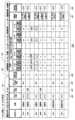
ステップS250にてサーバ10は、図16に示すようにアイコン情報J20を更新し、端末装置50からの次の要求等を待つ。図16に示すアイコン情報J20は、始業時刻8:50の時点の図13のアイコン情報J20に対して、始業時刻8:00から1時間経過後の9:00の状態の例を示しており、各利用者IDの利用者からの実績入力(完了情報の入力)が進んだ状態の例を示している。なお、アイコン情報J20の更新の詳細な説明については後述する。In step S250, the
ステップT230へ処理を進めた場合、端末装置50は、メニュー情報要求が入力されたか否かを判定する。端末装置50は、図15に示す実績入力画面G40の中の「メニューに戻る」が入力(選択)された場合(Yes)はステップT235へ処理を進め、「メニューに戻る」が入力(選択)されていない場合(No)はステップT215へ処理を戻す。When the process proceeds to step T230, the
ステップT235へ処理を進めた場合、端末装置50は、メニュー情報要求をサーバ10に送信し、サーバ10からのメニュー情報を待つ。そして端末装置50は、サーバ10からメニュー情報を受信すると、図3に示すフローチャートの符号Aの位置に戻り、ステップT025の処理にてメニュー画面G20(図5参照)を表示して利用者からの入力を待つ。なおメニュー情報は、図5に示すメニュー画面G20を端末装置50の表示装置に表示させるための情報である。If the process proceeds to step T235, the
ステップS255にてサーバ10は、メニュー情報要求を受信すると、メニュー情報を作成してステップS260へ処理を進める。When the
ステップS260にてサーバ10は、作成したメニュー情報を端末装置50に送信し、端末装置50からの次の要求等を待つ。In step S260, the
●[実績入力画面G40(図15)と利用者の操作]
次に、図15に示す実績入力画面G40の詳細について説明する。利用者ID:B001の利用者は、図15に示す実績入力画面G40に表示された作業予定項目J44に沿って作業を進めていき、作業が完了した作業予定項目J44に対して、作業が完了したことを示す完了情報(この例では、作業済情報である「V」印)を、実績入力部J45の作業済入力部J46へ入力し、「確認」を入力することでサーバ10の記憶装置12に記憶させる。[Results input screen G40 (FIG. 15) and user operations]
Next, details of the performance input screen G40 shown in Fig. 15 will be described. The user with user ID: B001 proceeds with the work according to the scheduled work items J44 displayed on the performance input screen G40 shown in Fig. 15, and for the scheduled work items J44 for which the work has been completed, inputs completion information indicating that the work has been completed (in this example, a "V" mark indicating that the work has been completed) into the work-completed input section J46 of the performance input section J45, and then inputs "confirm" to store the information in the
例えば利用者ID:B001の利用者は、図15に示す実績入力画面G40を表示装置に表示させ、自身のスケジュール情報J40に記憶されている業務の中から、今から作業する業務の個所を表示装置に表示させる。スケジュール情報J40をサーバ10の記憶装置12に記憶させた時点では、実績入力部J45はすべて空白状態(未入力状態)である。なお、実績入力部J45は、作業済入力部J46とチェック者日時記録部J47とを有している。例えば利用者ID:B001の利用者は、図15の例に示した実績入力画面G40の中から、作業予定項目J44=「1:ラベル印刷内容を確認」と「2:パソコンにてラベルを出力」、の作業内容を実施した場合、対応する実績入力部J45である作業済入力部J46(図15の符号J46Aの個所)をマウス等でクリックすることで、完了情報である作業済情報(V)印を入力する。For example, the user with user ID: B001 displays the results input screen G40 shown in FIG. 15 on the display device, and among the tasks stored in the user's schedule information J40, the user has the display device display the task that the user is about to perform. When the schedule information J40 is stored in the
そして利用者が、図15に示す実績入力画面G40の「確認」を入力(選択)すると、上述した完了情報が入力されたスケジュール情報J40がサーバ10に送信される。サーバ10は、受信したスケジュール情報J40において、新たに完了情報が入力された作業済入力部J46(図15の例では、符号J46Aの個所)に対応するチェック者日時記録部J47(図15の例では、符号J47Aの個所)に、上述したように氏名と日時を記憶し、さらに、実績作業完了項目数J40Cの値を再計算して更新し、スケジュール情報を更新して記憶する。図15の例では、符号J46Aの個所に完了情報が入力されたことで、実績作業完了項目数J40Cの値が「2」とされた例を示している。When the user then inputs (selects) "Confirm" on the performance input screen G40 shown in FIG. 15, the schedule information J40 with the completion information inputted therein is sent to the
●[ステップS250でのアイコン情報J20(図16)の更新]
アイコン情報J20(図16参照)の各時刻までの目標と実績J26Xにおける「9:00」の欄の実績作業完了項目数J26Zには、始業時刻8:00~8:59の期間に端末装置50からスケジュール情報J40を受信して更新した際の実績作業完了項目数J40C(図15参照)の値がコピーされる。同様に、各時刻までの目標と実績J26Xにおける「10:00」の欄の実績作業完了項目数J26Zには、9:00~9:59の期間に端末装置50からスケジュール情報J40を受信して更新した際の実績作業完了項目数J40C(図15参照)の値がコピーされる。[Updating the icon information J20 (FIG. 16) in step S250]
The number of completed work items J40C (see FIG. 15) when schedule information J40 is received from
例えば利用者ID:B001の利用者が、端末装置50を操作して図15に示す実績入力画面G40に示すように完了情報を入力した後、8:50に「確認」を入力すると、サーバ10は、8:50に利用者ID:B001を含むスケジュール情報J40を受信する。そしてサーバ10は、スケジュール情報J40を受信して更新した際、利用者ID:B001、実績作業完了項目数「2」、受信時刻8:50等を用いて、図16に示すアイコン情報J20の利用者ID:B001に対応する「9:00」の実績作業完了項目数J26Zの欄(符号J26AAの個所)に、「2」を記憶する。For example, if a user with user ID: B001 operates
サーバ10を動作させる稼働状況表示プログラムは、上記の「実績入力支援処理」に説明したように、サーバ10(コンピュータ)を、スケジュール情報に記憶されているそれぞれの作業予定項目に対して作業が完了した旨を示す完了情報の入力を受け付け、完了情報をそれぞれの作業予定項目に対応付けて記憶させる、実績入力支援手段11C(図2参照)として機能させる。The operation status display program that operates the
●[サーバ10による稼働状況(稼働率)算出処理(図17)と、アイコン情報J20(図16)の更新]
次に、サーバ10が定期的に実行する「稼働状況算出処理」について、図17に示すフローチャートを用いて説明する。サーバ10は、例えば、始業時刻8:00から1時間経過後の9:00、2時間経過後の10:00、・・・7時間経過後(12:00~13:00を除く)の16:00、8時間経過後(12:00~13:00を除く)の17:00に、以下に説明する稼働状況算出処理を自動的に起動してステップS510へ処理を進め、アイコン情報J20(図16参照)の稼働率J27を算出して更新し、稼働状況表示画面G50(図18参照)を作成する。[Operation Status (Operation Rate) Calculation Process by Server 10 (FIG. 17) and Update of Icon Information J20 (FIG. 16)]
Next, the "operation status calculation process" periodically executed by the
ステップS510にてサーバ10は、稼働状況算出タイミングであるか否かを判定する。この場合、9:00、10:00、11:00、12:00、14:00(12:00~13:00は休憩)、15:00、16:00、17:00、のいずれかの時刻であるか否かを判定する。サーバ10は、稼働状況算出タイミングである場合(Yes)はステップS515へ処理を進め、そうでない場合(No)は処理を終了する。なお、上記のタイミングで図17の処理を起動しているので、ステップS510は省略してもよい。In step S510, the
ステップS515へ処理を進めた場合、サーバ10は、利用者IDごとの稼働率(稼働状況)を算出してステップS520へ処理を進める。なお、利用者IDごとの稼働率の算出手順については後述する。If the process proceeds to step S515, the
なお、サーバ10は、例えば始業時刻8:00から1時間経過後の9:00の場合、アイコン情報J20(図16参照)における「ログイン状態J23」=「ログアウト」、かつ「スケジュールの登録有無J25」=「-(登録無し)」となっている利用者IDの利用者は休業中で出社していない、と判定し、該当する利用者ID(図16の例では利用者ID:A002)に対応する「出張/休業J24」に「休業」を記憶する。なお図16のアイコン情報J20の例では、利用者ID:A002に対応する「出張/休業J24」に、「休業」を記憶した例を示している。For example, when it is 9:00, one hour after the start of work at 8:00, the
ステップS520にてサーバ10は、算出した稼働率を用いてアイコン情報を更新し、ステップS525へ処理を進める。なお、アイコン情報の更新の詳細については後述する。In step S520, the
ステップS525にてサーバ10は、更新したアイコン情報に基づいて、稼働状況表示画面G50(図18参照)を作成して記憶し、図17に示す処理を終了する。なお、稼働状況表示画面G50の作成手順については後述する。In step S525, the
●[利用者IDごとの稼働率(稼働状況)の算出と、アイコン情報(図16)の更新]
サーバ10は、図16に示すアイコン情報J20の「各時刻までの目標と実績J26X」の各時刻である9:00、10:00、11:00、12:00、14:00(12:00~13:00は休憩)、15:00、16:00、17:00の各時刻に達するごとに、稼働状況算出処理を起動し、利用者IDごとの稼働率J27を算出して記憶する。[Calculation of operation rate (operation status) for each user ID and update of icon information (FIG. 16)]
The
例えばサーバ10は、9:00に達した場合、利用者IDごとの、「各時刻までの目標と実績J26X」における「9:00」の「目標作業完了項目数J26Y」と「実績作業完了項目数J26Z」を用いて、利用者IDごとの、9:00の時点の稼働率を算出する。例えば利用者ID:B001に対しては、サーバ10は、「9:00」の実績作業完了項目数である「2(符号J26AAの個所の数値)」/目標作業完了項目数である「3(符号J26Aの個所の数値)」=0.666と算出し、利用者ID:B001に対応する稼働率J27に「66.6%」を記憶する。For example, when it reaches 9:00, the
またサーバ10は、算出した稼働率を、数値に応じた3段階に分類(評価)し、評価結果をアイコン情報J20(図16参照)の稼働率J27の数値とともに記憶する。例えばサーバ10は、稼働率が95%以上である場合を「良好」、95%未満かつ80%以上を「低下」、80%未満を「悪化」、という具合の3段階に評価する。そしてサーバ10は、図16に示すように、アイコン情報J20の稼働率J27の数値に加えて、3段階の評価結果を記憶する。図16のアイコン情報J20の例において例えば利用者ID:B001に対しては、サーバ10は、稼働率=2/3=66.6%と算出し、3段階評価=「悪化」と評価し、対応する稼働率J27(符号J27Aの個所)には、「66.6%(悪化)」を記憶する。また図16のアイコン情報J20における、符号J27B~J27Dの個所も同様に算出されて記憶される。The
なお、サーバ10は、図16に示すアイコン情報J20において、出張/休業J24=「休業」の利用者IDに対応する稼働率J27には「-(休業中)」を記憶する(図16の例では、符号J27Eの個所)。またサーバ10は、図16に示すアイコン情報J20において、出張/休業J24=「出張」の利用者IDに対応する稼働率J27には「-(出勤中)」を記憶する(図16の例では、符号J27Fの個所)。またサーバ10は、図16に示すアイコン情報J20において、ログイン状態J23=「ログイン」、かつ、スケジュールの登録有無J25=「-(登録なし)」の利用者IDに対応する稼働率J27には「-(出勤中)」を記憶する(図16の例では、符号J27Gの個所)。In the icon information J20 shown in FIG. 16, the
サーバ10を動作させる稼働状況表示プログラムは、上記の「稼働状況算出処理」に説明したように、サーバ10(コンピュータ)を、所定期間(この場合、本日の始業時刻から終業時刻)の開始からの経過時間に対応させて、利用者IDごとに、スケジュール情報に記憶されている作業予定項目の数に関連する作業予定項目関連数(目標作業完了項目数J26Y)と、完了情報が記憶されている作業予定項目の数である実績作業完了項目数J26Zと、に基づいて、利用者IDごとに稼働状況(稼働率)を算出させる、稼働状況算出手段11D(図2参照)として機能させる。The operation status display program that operates the
上述したように、サーバ10は、利用者IDごとに、所定期間の期間開始時刻からの所定の経過時間までに(この場合、本日の始業時刻8:00からの1時間、2時間、3時間・・経過までに)、完了情報が記憶されるべき作業予定項目の数(作業予定項目関連数に相当)である目標作業完了項目数と、実績作業完了項目数と、を求め、利用者IDごとの目標作業完了項目数に対する実績作業完了項目数の割合(=実績作業完了項目数/目標作業完了項目数)を、利用者IDごとの稼働状況(稼働率)として算出する。As described above, for each user ID, the
●[稼働状況表示画面G50(図18)の詳細]
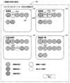
次に図18を用いて、サーバ10が作成する稼働状況表示画面G50の詳細について説明する。稼働状況表示画面G50では、利用者IDごとに割付けられた主アイコンG52を稼働状況(稼働率)に応じた表示状態とされて表示される。なお図18に示す例では、主アイコンG52として、稼働率に応じた色彩とされた円形状のアイコンを用いている。[Details of the operation status display screen G50 (FIG. 18)]
Next, the operation status display screen G50 created by the
図18に示すように、稼働状況表示画面G50では、表示グループG51ごとに(利用者の所属するグループごとに)、利用者IDに割付けられた個々の主アイコンG52が表示される。図18に示す例では、利用者IDに対応する利用者の部署ごとに表示グループG51が形成されている。例えば営業部には、利用者ID:B001~B008の利用者が所属しており、表示グループG51=「営業部」の領域に表示されている。また利用者ID:B001の利用者に対応する主アイコン(符号J52Aの個所)には、利用者IDである「B001」が表示されている。As shown in FIG. 18, on the operation status display screen G50, for each display group G51 (for each group to which a user belongs), an individual main icon G52 assigned to a user ID is displayed. In the example shown in FIG. 18, a display group G51 is formed for each department of users corresponding to the user ID. For example, the sales department includes users with user IDs B001 to B008, and is displayed in the display group G51 = "Sales department" area. In addition, the main icon (indicated by symbol J52A) corresponding to the user with user ID B001 displays the user ID "B001".
各主アイコンG52は、対応付けられている利用者IDの利用者の稼働率に応じて3段階の色彩で表示状態が変更されている。例えば、稼働率が95%以上の場合は緑色(稼働率良好)、稼働率が95%未満かつ80%以上の場合はオレンジ色(稼働率低下)、稼働率が80%未満の場合は赤色(稼働率悪化)、に表示状態が変更されて表示されている。図18の例では、緑色をドットハッチング、オレンジ色を横線ハッチング、赤色を斜めクロスハッチングで表現している。The display state of each main icon G52 is changed to three different colors depending on the operating rate of the user with the associated user ID. For example, if the operating rate is 95% or higher, the display state is changed to green (good operating rate), if the operating rate is less than 95% and greater than or equal to 80%, the display state is changed to orange (low operating rate), and if the operating rate is less than 80%, the display state is changed to red (worsening operating rate). In the example of Figure 18, green is represented by dot hatching, orange by horizontal line hatching, and red by diagonal cross hatching.
また、出勤しているが、社外に出張中の利用者や、業務候補情報J30(図10)に用意されていない突発的に発生した業務などスケジュール情報J40(図9、図12参照)を作成できない利用者(利用者ID)に対応する主アイコンは、実線の輪郭とされた白色の主アイコンにて表示されている(図18の例では、利用者ID:B002、B003の主アイコン(符号G52Eの個所))。また、出勤していない休業中の利用者(利用者ID)に対応する主アイコンは、点線の輪郭とされた白色の主アイコンにて表示されている(図18の例では、利用者ID:A002の主アイコン(符号G52Dの個所))。Also, the main icon corresponding to a user (user ID) who is at work but out of the office, or who cannot create schedule information J40 (see Figs. 9 and 12) due to an unexpected task that is not prepared in the task candidate information J30 (Fig. 10), is displayed as a white main icon with a solid outline (in the example of Fig. 18, the main icons for user IDs: B002 and B003 (G52E)). Also, the main icon corresponding to a user (user ID) who is not at work and is on leave is displayed as a white main icon with a dotted outline (in the example of Fig. 18, the main icon for user ID: A002 (G52D)).
●[稼働状況表示画面G50(図18)の作成手順]
例えば9:00の時点の稼働状況表示画面G50(図18参照)を作成する場合、サーバ10は、まず図18に示す表示グループG51の各領域を決める。この場合、図16に示すアイコン情報J20の「部署」を表示グループG51とするので、サーバ10は、アイコン情報J20の「部署」である「総務部」、「営業部」、「生産技術部」、「製造部1課」のそれぞれの表示グループG51の各領域を決める(図18参照)。[Procedure for creating the operation status display screen G50 (FIG. 18)]
For example, when creating an operation status display screen G50 (see FIG. 18) as of 9:00, the
次にサーバ10は、図16のアイコン情報J20に基づいて、各表示グループG51(この場合、「部署」)内に、対応する利用者IDの主アイコンを配置する。例えばアイコン情報J20において利用者ID:B001~B008の部署=「営業部」である場合、サーバ10は、表示グループG51=「営業部」の領域に、「部署」=「営業部」である利用者ID:B001~B008の主アイコンG52を配置する(図18参照)。Next, the
次にサーバ10は、図16のアイコン情報J20の稼働率J27に記憶されている情報に基づいて、配置した各主アイコンの表示状態を変更する。例えば図16のアイコン情報J20において、利用者ID:B001に対応する稼働率J27(符号J27A)には「66.6%(悪化)」が記憶されているので、サーバ10は、利用者ID:B001に対応する主アイコン(図18の符号G52A)の表示状態を、「稼働率悪化」に対応付けられた赤色(80%未満)に変更して表示する。同様に、図16のアイコン情報J20において利用者ID:C001に対応する稼働率J27(符号J27B)には「80.0%(低下)」が記憶されているので、サーバ10は、利用者ID:C001に対応する主アイコン(図18の符号G52B)の表示状態を、「稼働率低下」に対応付けられたオレンジ色(95%未満かつ80%以上)に変更して表示する。同様に、図16のアイコン情報J20において利用者ID:D001に対応する稼働率J27(符号J27C)には「100.0%(良好)」が記憶されているので、サーバ10は、利用者ID:D001に対応する主アイコン(図18の符号G52C)の表示状態を、「稼働率良好」に対応付けられた緑色(95%以上)に変更して表示する。他の主アイコンの色彩も同様に変更する。Next, the
次にサーバ10は、図16のアイコン情報J20において、稼働率J27に「-(休業中)」が記憶されている利用者ID(図16の例では、利用者ID:A002(図16の符号J27D)が該当)に対応する主アイコン(図18の符号G52D)の表示状態を、「停止中・休業中」に対応付けられた点線の輪郭の白色に変更して表示する。Next, the
次にサーバ10は、図16のアイコン情報J20において、稼働率J27に「-(出勤中)」が記憶されている利用者ID(図16の例では、利用者ID:B002、B003(図16の符号J27F、J27G)が該当)に対応する主アイコン(図18の符号G52)の表示状態を、「稼働中・出勤中」に対応付けられた実線の輪郭の白色に変更して表示する。Next, the
なおサーバ10は、作成した稼働状況表示画面G50(図18参照)を記憶装置12に記憶する。そしてサーバ10は、後述する「稼働状況表示処理」にて、端末装置50からの要求があれば、稼働状況表示画面G50を表示させるための稼働状況表示情報を作成して端末装置に送信する。The
●[稼働状況表示処理(図19)と、稼働状況表示画面G50の例(図18)]
次に、図5に示すメニュー画面G20から「稼働状況を表示」が入力(選択)された場合の処理である「稼働状況表示処理」について説明する。利用者ID:B001の利用者が、図5に示すメニュー画面G20から「稼働状況を表示」を入力(選択)すると、端末装置50は、図19に示すステップT310へ処理を進める。[Operation status display process (FIG. 19) and example of operation status display screen G50 (FIG. 18)]
Next, a description will be given of the "operational status display process" which is the process performed when "display operational status" is input (selected) from the menu screen G20 shown in Fig. 5. When the user with user ID: B001 inputs (selects) "display operational status" from the menu screen G20 shown in Fig. 5, the
ステップT310にて端末装置50は、稼働状況表示情報要求をサーバ10に送信し、サーバ10からの応答を待つ。In step T310, the
ステップS310にてサーバ10は、稼働状況表示情報要求を受信すると、記憶装置12に記憶されている稼働状況表示画面G50から、端末装置50の表示装置に稼働状況表示画面G50(図8参照)を表示させるための情報である稼働状況表示情報を作成し、ステップS315へ処理を進める。なお、サーバ10による稼働状況表示画面G50(図18参照)の作成手順については上述したとおりである。When the
ステップS315にてサーバ10は、作成した稼働状況表示情報を端末装置50に送信し、端末装置50からの次の要求等を待つ。In step S315, the
ステップT315にて端末装置50は、稼働状況表示情報を受信すると、図18の例に示す稼働状況表示画面G50を表示装置に表示し、ステップT320へ処理を進める。なお、稼働状況表示画面G50の詳細は上述したとおりである。When the
ステップS320にて端末装置50は、メニュー情報要求が入力されたか否かを判定する。端末装置50は、図18に示す稼働状況表示画面G50の中の「メニューに戻る」が入力(選択)された場合(Yes)はステップT325へ処理を進め、「メニューに戻る」が入力(選択)されていない場合(No)はステップT315へ処理を戻す。In step S320, the
ステップT325へ処理を進めた場合、端末装置50は、メニュー情報要求をサーバ10に送信し、サーバ10からのメニュー情報を待つ。そして端末装置50は、サーバ10からメニュー情報を受信すると、図3に示す符号Aの位置に戻り、ステップT025の処理にてメニュー画面G20(図5参照)を表示して利用者からの入力を待つ。If the process proceeds to step T325, the
ステップS320にてサーバ10は、メニュー情報要求を受信すると、メニュー情報を作成し、ステップS325へ処理を進める。なお、メニュー情報は、端末装置50にメニュー画面G20(図5参照)を表示させるための情報である。When the
ステップS325にてサーバ10は、作成したメニュー情報を端末装置50に送信し、端末装置50からの次の要求等を待つ。In step S325, the
サーバ10が、稼働状況表示画面G50を表示させるための稼働状況表示情報を作成する際、アイコン情報J20を用いて作成する。図16の例に示すように、アイコン情報J20には、利用者IDごとの稼働率J27がサーバ10にて算出されて記憶されるが、サーバ10の稼働率J27の算出は、9:00の時点、10:00の時点、11:00の時点、12:00の時点、14:00の時点、15:00の時点、16:00の時点、17:00の時点にて算出されて記憶される。When the
上述したように、サーバ10は、9:00、10:00・・・16:00、17:00に稼働状況表示画面G50を作成するので、例えば利用者ID:B001の利用者が9:30に、図5に示すメニュー画面G20から「稼働状況を表示」を入力すると、サーバ10が9:00の時点に作成した稼働状況表示画面G50(図18参照)が、端末装置50の表示装置に表示される。図18に示す稼働状況表示画面G50を見れば、利用者は、一目で各利用者の稼働状況(稼働率)を確認することが可能であり、稼働率低下(オレンジ色)や稼働率悪化(赤色)の利用者を瞬時に認識できる。従って、フォローが必要と思われる利用者を、適切にフォローすることが可能となり、「人」の生産性をより向上させることができる。As described above, the
上述したように、サーバ10を動作させる稼働状況表示プログラムは、利用者IDごとに割付けられた主アイコンを表示装置に一覧状に表示させるとともに、利用者IDごとの主アイコンの表示状態(この場合、色彩)を、利用者IDごとの稼働状況(稼働率)に応じて変更させる、稼働状況表示手段11E(図2参照)として機能させる。As described above, the operation status display program that operates the
●[第2の実施の形態(図20~図27)]
次に図20~図27を用いて、稼働状況表示プログラムの第2の実施の形態について説明する。第2の実施の形態では、利用者ID:C001の利用者を例として説明する。第2の実施の形態では、業務候補情報J30及びスケジュール情報J40(図21参照)に含まれている業務J32の作業予定項目J34A~J34E(図22参照)に示すように、測定対象物の測定が含まれている点が、第1の実施の形態とは異なる。[Second embodiment (FIGS. 20 to 27)]
Next, a second embodiment of the operating status display program will be described with reference to Figures 20 to 27. In the second embodiment, a user with user ID: C001 will be described as an example. The second embodiment differs from the first embodiment in that it includes measurement of a measurement target, as shown in the scheduled work items J34A to J34E (see Figure 22) of task J32 included in task candidate information J30 and schedule information J40 (see Figure 21).
図23の例に示すように、スケジュール情報J40の作業予定項目J44A~J44Eが測定対象物の測定である場合、実績入力部J45が、測定値を入力する測定値入力部J461、J462等とされている。また入力された測定値に対して、サーバ10が評価を行い、測定値の評価結果を、図26のアイコン情報J20の測定値評価結果J28に記憶する。そしてサーバ10は、図27に示す稼働状況表示画面G50を作成する際、図26のアイコン情報J20の稼働率J27に基づいて主アイコンG52を種々の表示状態にして表示し、図26のアイコン情報J20の測定値評価結果J28に基づいて補助アイコンG53を種々の表示状態にして表示する。以下、第1の実施の形態との相違点について主に説明する。As shown in the example of FIG. 23, when the planned work items J44A-J44E of the schedule information J40 are measurements of measurement objects, the performance input section J45 is made into measurement input sections J461, J462, etc., for inputting measurement values. The
●[スケジュール作成支援処理(図20)]
次に図20を用いて、第2の実施の形態のスケジュール作成支援処理について説明する。図20に示す第2の実施の形態のスケジュール作成支援処理は、図8に示す第1の実施の形態のスケジュール作成支援処理に対して、ステップS142A~S142Eが追加されている点と、ステップS145で送信されるスケジュール情報(測定値入力部を有する場合がある)が異なるが、他は同じである。以下、相違点を主に説明する。[Schedule Creation Support Process (Fig. 20)]
Next, the schedule creation support process of the second embodiment will be described with reference to Fig. 20. The schedule creation support process of the second embodiment shown in Fig. 20 differs from the schedule creation support process of the first embodiment shown in Fig. 8 in that steps S142A to S142E are added and that the schedule information sent in step S145 (which may have a measurement value input section) is different, but otherwise is the same. The following mainly describes the differences.
ステップS140にてサーバ10は、スケジュール情報を受信すると、受信したスケジュール情報を記憶装置12に記憶(更新)し、ステップS142Aへ処理を進める。サーバ10は、対象の利用者IDの本日分のスケジュール情報がすでに記憶装置12に記憶されている場合、対象の利用者IDの本日分のスケジュール情報を上書きして記憶する。またサーバ10は、対象の利用者IDのスケジュール情報が記憶装置12に記憶されていない場合、対象の利用者IDの本日分のスケジュール情報として新規に記憶する。In step S140, when the
ステップS142Aにてサーバ10は、記憶したスケジュール情報J40(図23参照)の作業予定項目の中に、実績入力部J45(図23参照)が測定値入力部J461、J462(図23参照)である作業予定項目が有るか否かを判定する。なお、作業予定項目には、作業IDが割付けられており、サーバ10は、作業IDを確認することで測定値入力部があるか否かを判定できる。例えば図23にて符号J44Bの作業予定項目である「04工程内品質チェック」-「003製品測定(月初)」-「4バリ高さ<0.1 ダイヤルゲージで測定」には、作業ID「04-003-4」が割付けられている。サーバ10は、測定値入力部が有る作業予定項目がある場合(Yes)はステップS142Bへ処理を進め、測定値入力部が有る作業予定項目が無い場合(No)はステップS145へ処理を進める。In step S142A, the
ステップS142Bへ処理を進めた場合、サーバ10は、対象の利用者ID(この場合、利用者ID:C001)の過去のスケジュール情報(記憶装置12に記憶されている)を検索し、ステップS142Cへ処理を進める。この場合、サーバ10は、今回記憶したスケジュール情報の中で、測定値入力部を有する作業予定項目の作業IDに対して、対象の利用者ID:C001を有する過去のスケジュール情報の中から一致する作業IDを検索する。検索の場合、1日前の利用者ID:C001のスケジュール情報、2日前の利用者ID:C001のスケジュール情報、という具合に順番にさかのぼって検索する。また、例えば1か月前までさかのぼっても一致する作業IDが無い場合は検索を中止し、一致した作業IDが見つかった場合は、その時点で検索を中止する。If the process proceeds to step S142B, the
ステップS142Cにてサーバ10は、対象の利用者IDの過去のスケジュール情報の中に、作業IDが一致する作業予定項目があったか否かを判定する。サーバ10は、一致する作業IDがあった場合(Yes)はステップS142Dへ処理を進め、一致する作業IDが無かった場合(No)はステップS145へ処理を進める。In step S142C, the
ステップS142Dへ処理を進めた場合、サーバ10は、一致した過去の作業予定項目の測定値入力部J462に記憶されている測定値情報を抽出し、ステップS142Eへ処理を進める。なお、図25に示すように、測定値入力部は、製品ロットの初品(ロットの初期の頃の製品)の測定値である測定値入力部J461と、製品ロットの終品(ロットの終期の頃の製品)の測定値である測定値入力部J462が有り、この場合、測定値入力部J462のほうの測定値情報を抽出する。If processing proceeds to step S142D, the
ステップS142Eにてサーバ10は、抽出した測定値情報を、ステップS140にて新たに記憶したスケジュール情報の中の対応する作業予定項目の過去測定値入力部J48(図23参照)に記憶(コピー)し、スケジュール情報を更新し、ステップS145へ処理を進める。この結果、図23の例に示すように、作業予定項目J44A~J44Eのそれぞれに対応する過去測定値入力部J48には、過去に測定したときの測定値情報がコピーされる。In step S142E, the
このようにサーバ10は、スケジュール情報の作業予定項目に過去測定値入力部が対応付けされている場合には、対象の利用者IDの過去のスケジュール情報を記憶装置から抽出し、新たに記憶したスケジュール情報の過去測定値入力部に対応付けられた作業予定項目の作業内容と一致する作業予定項目の作業内容が、記憶装置から抽出した過去のスケジュール情報に有る場合には、抽出した過去のスケジュール情報における作業内容が一致した作業予定項目に対応付けられた測定値入力部に記憶されている測定値情報を、新たに記憶したスケジュール情報における作業内容が一致した作業予定項目に対応付けられた過去測定値入力部に記憶する。In this way, when a past measurement value input section is associated with a planned work item in the schedule information, the
ステップS145にてサーバ10は、ステップS140またはステップS142Eにて更新したスケジュール情報J40を端末装置50に送信し、ステップS150へ処理を進める。更新されたスケジュール情報を受信した端末装置50は、ステップT115へ戻った際、更新されたスケジュール情報を含むスケジュール作成画面G30(図21参照)を、表示装置に表示する。In step S145, the
これにより、利用者ID:C001の利用者は、実績入力にて測定値を入力する際、過去の測定値と、今回の測定値とを比較して、安定傾向、増加傾向、減少傾向などを推定することが可能であり、不具合の発生を予測して未然に防止できる可能性が高くなる。As a result, when the user with user ID: C001 inputs a measurement value in the performance input screen, they can compare the current measurement value with past measurements to estimate whether the measurement value is stable, increasing, or decreasing, and can therefore more easily predict and prevent malfunctions.
●[スケジュール作成画面G30(図21)]
スケジュール作成画面G30は、図21に示すように、第1の実施の形態のスケジュール作成画面G30(図9参照)と同様である。図21の例は、利用者ID:C001(生産技術部)の利用者のスケジュール作成画面G30の例であり、業務グループ名称J31=「04工程内品質チェック」、業務J32(候補業務)=「003製品測定(月初)」を、自身のスケジュール情報に追加した例を示している。[Schedule creation screen G30 (Figure 21)]
The schedule creation screen G30 is similar to the schedule creation screen G30 (see FIG. 9) of the first embodiment, as shown in Fig. 21. The example in Fig. 21 is an example of the schedule creation screen G30 of a user with user ID: C001 (production technology department), and shows an example in which a task group name J31 = "04 in-process quality check" and a task J32 (candidate task) = "003 product measurement (beginning of month)" have been added to the user's own schedule information.
●[測定値入力部J35を有する業務候補情報J30の作業予定項目の例(図22)]
図22は、図21に示した、業務グループ名称J31=「04工程内品質チェック」、業務J32(候補業務)=「003製品測定(月初)」、に含まれている作業予定項目J34A~J34Eの例を示している。作業予定項目J34A~J34Eには、所定の測定値を用いて指定された測定対象物を測定する作業内容等が含まれている。なお、図22におけるJ33Aには、対象製品を製造する設備の場所、測定対象物の製品番号等が指定されている。[Example of scheduled work items in job candidate information J30 having a measurement input section J35 (FIG. 22)]
Fig. 22 shows an example of scheduled work items J34A to J34E included in the work group name J31 = "04 In-process quality check" and work J32 (candidate work) = "003 Product measurement (beginning of month)" shown in Fig. 21. The scheduled work items J34A to J34E include work content for measuring a specified measurement object using a predetermined measurement value. Note that in J33A in Fig. 22, the location of the equipment that manufactures the target product, the product number of the measurement object, etc. are specified.
●[スケジュール情報J40の過去測定値入力部J48に自動的に過去の測定値が入力された例(図23)]
図23に示すスケジュール情報J40は、図22に示す業務候補情報J30に対して、上述したサーバ10の処理(ステップS142A~S142E)によって、過去に測定した際の測定値情報が自動的に抽出されて、過去測定値入力部J48に記憶(入力)された状態の例を示している。[An example in which past measurement values are automatically input into the past measurement value input section J48 of the schedule information J40 (FIG. 23)]
The schedule information J40 shown in FIG. 23 shows an example of a state in which measurement value information from past measurements is automatically extracted from the job candidate information J30 shown in FIG. 22 by the above-mentioned processing of the server 10 (steps S142A to S142E) and stored (input) in the past measurement value input section J48.
図20におけるステップT125にて端末装置50からサーバ10に送信されるスケジュール情報には、過去測定値入力部J48(図23参照)は空白の状態である。しかし、ステップS142A~S142Eにて、サーバ10が、過去のスケジュール情報を用いて自動的に過去測定値入力部J48(図23参照)を記憶(入力)して、ステップD145にて更新したスケジュール情報を送信してくれるので、利用者の手間を省略することができて便利である。In the schedule information sent from the
●[実績入力支援処理(図24)]
次に図24を用いて、第2の実施の形態の実績入力支援処理について説明する。図24に示す第2の実施の形態の実績入力支援処理は、図14に示す第1の実施の形態の実績入力支援処理に対して、ステップS242A~S242Cが追加されている点と、ステップS245で送信されるスケジュール情報(測定値入力部を有する場合がある)と、ステップS250にてアイコン情報の更新内容(測定値評価結果を更新する場合がある)が異なり、他は同じである。以下、相違点を主に説明する。[Results input support process (Fig. 24)]
Next, the result input support process of the second embodiment will be described with reference to Fig. 24. The result input support process of the second embodiment shown in Fig. 24 is the same as the result input support process of the first embodiment shown in Fig. 14 except that steps S242A to S242C are added, and the schedule information (which may have a measurement value input section) sent in step S245 and the update contents of the icon information (which may update the measurement value evaluation result) in step S250 are different. The following mainly describes the differences.
ステップS240にてサーバ10は、スケジュール情報を受信すると、受信したスケジュール情報を記憶装置12に記憶(更新)し、ステップS242Aへ処理を進める。When the
ステップS242Aにてサーバ10は、更新したスケジュール情報に、測定値入力部J461、J462(図25参照)があるか否かを判定する。上述したように、例えば図25の作業予定項目J44B(「04工程内品質チェック」-「003製品測定(月初)」-「4バリ高さ<0.1 ダイヤルゲージで測定」)には、作業ID「04-003-4」が割付けられており、サーバ10は、作業IDを確認することで、測定値入力部の有無を判定することができる。サーバ10は、更新したスケジュール情報に、測定値入力部を有する作業予定項目が有る場合(Yes)はステップS242Bへ処理を進め、そうでない場合(No)はステップS245へ処理を進める。In step S242A, the
ステップS242Bへ処理を進めた場合、サーバ10は、測定値入力部J461、J462(図25参照)に、完了情報(測定値情報)の入力があるか否かを判定する。サーバ10は、測定値入力部に完了情報(測定値情報)の入力がある場合(Yes)はステップS242Cへ処理を進め、そうでない場合(No)はステップS245へ処理を進める。If the process proceeds to step S242B, the
ステップS242Cへ処理を進めた場合、サーバ10は、入力された完了情報(測定値情報)を評価し、評価結果とともにスケジュール情報を更新して記憶装置12に記憶し、ステップS245へ処理を進める。つまり、サーバ10は、測定値入力部J461、J462(図25参照)に測定値情報が入力されると、測定値情報を完了情報として、測定値入力部J461、J462(図25参照)が対応付けられている作業予定項目J44A~J44E(図25参照)に対応付けて記憶する。If the process proceeds to step S242C, the
例えば図25の例に示す作業予定項目J44Bには、許容範囲「<0.1(0.1[mm]未満)」が設定されている。また許容範囲には、3段階の評価基準が対応付けられている。例えば許容範囲「<0.1(0.1[mm]未満)には、品質良好(0.05[mm]未満)、品質低下(0.05[mm]以上、かつ0.09[mm]未満)、品質危険(0.09[mm]以上)、が対応付けられている。そしてサーバ10は、許容範囲と、入力された測定値情報との関係に基づいて、測定値評価結果を上記の3段階(品質良好/品質低下/品質危険)に分類する。なお、サーバ10による測定値の評価については後述する。For example, the work schedule item J44B shown in the example of Figure 25 has a tolerance range of "<0.1 (less than 0.1 mm)". The tolerance range is associated with three evaluation criteria. For example, the tolerance range of "<0.1 (less than 0.1 mm)" is associated with good quality (less than 0.05 mm), poor quality (0.05 mm or more and less than 0.09 mm), and dangerous quality (0.09 mm or more). The
ステップS245にてサーバ10は、ステップS240またはステップS242Cにて更新したスケジュール情報を端末装置50に送信し、ステップS250へ処理を進める。なお、更新したスケジュール情報を受信した端末装置50は、ステップT215へ戻った際、更新したスケジュール情報を含む実績入力画面G40(図25参照)を表示装置に表示する。In step S245, the
ステップS250にてサーバ10は、図26に示すようにアイコン情報J20を更新し、端末装置50からの次の要求を待つ。このステップS250では、図14に示す第1の実施の形態のステップS250でのアイコン情報の更新(実績作業完了項目数J26Zの更新)に加えて、測定値評価結果J28の更新を実施する。なお、アイコン情報J20の更新の詳細については後述する。In step S250, the
●[実績入力画面G40(測定値入力部への測定値情報の入力画面)の例(図25)]
利用者ID:C001の利用者は、ステップT215にて端末装置50の表示装置に表示された実績入力画面G40(図25参照)にて、完了情報を入力する。完了情報を入力する前のスケジュール情報J40の状態は、図23の例に示すとおりである。例えば利用者ID:C001の利用者は、図25の例に示す実績入力画面G40にて、作業予定項目J44Bにて指定された測定対象物(コイルNo A5-K0)を、所定の測定装置(ダイヤルゲージ)で測定して取得した測定値(バリ高さ)を、測定値入力部J461B、J462Bに入力する。[Example of performance input screen G40 (screen for inputting measurement value information into the measurement value input unit) (FIG. 25)]
In step T215, the user with user ID: C001 inputs completion information on the performance input screen G40 (see FIG. 25) displayed on the display device of the
なお利用者の測定は、初期の頃のロットの該当製品の測定と、終期の頃のロットの該当製品の測定と、の2回が指定されている。利用者は、初期の頃のロットの該当製品の測定値を測定値入力部J461Bに入力し、終期の頃のロットの該当製品の測定値を測定値入力部J462Bに入力する。例えば図25に示す測定値入力部J461Bに測定値が入力されると、測定値入力部J461に対応するチェック者日時記録部J471Bに、チェック者の氏名(この場合、利用者ID:C001の利用者の氏名「C1」)と、日時情報(図25の例では、「2021/1/27 9:32:00」)が、第1の実施の形態で説明したようにサーバ10によって自動的に入力される。測定値入力部J461Bから測定値を削除した場合、対応するチェック者日時記録部J471Bは空白状態(未入力状態)に自動的に戻される。The user is specified to measure two times, one for the corresponding product of the initial lot and one for the corresponding product of the final lot. The user inputs the measurement value of the corresponding product of the initial lot into the measurement value input section J461B, and the measurement value of the corresponding product of the final lot into the measurement value input section J462B. For example, when a measurement value is input into the measurement value input section J461B shown in FIG. 25, the name of the checker (in this case, the name of the user "C1" of user ID: C001) and the date and time information (in the example of FIG. 25, "2021/1/27 9:32:00") are automatically input by the
また利用者が、図25の実績入力画面G40にて測定値入力部J461Bに測定値「0.04」を入力して「確認」を入力すると、チェック者日時記録部J471Bが、第1の実施の形態で説明したようにサーバ10のステップS242Cにて自動的に入力される。またサーバ10は、ステップS242Cにて、図25の測定値入力部J461Bに入力された測定値に対して、設定されている許容範囲に基づいて評価した結果を、測定値入力部J461Bの色彩に反映する。When the user inputs the measurement value "0.04" in the measurement value input section J461B on the performance input screen G40 in FIG. 25 and selects "Confirm," the checker date and time recording section J471B is automatically input in step S242C of the
例えば図25の測定値入力部J461Bには、許容範囲「<0.1(0.1[mm]未満)」が設定されており、評価基準として品質良好(0.05[mm]未満、「緑色」)、品質低下(0.05[mm]以上、かつ0.09[mm]未満、「オレンジ色」)、品質危険(0.09[mm]以上、「赤色」)、が対応付けられている。この場合、サーバ10は、入力された「0.04」に対して「品質良好、緑色」」と判定し、スケジュール情報の測定値入力部J461Bを緑色に変更し、図25の測定値評価結果J40Dに「品質良好」を記憶する。For example, the measurement input section J461B in FIG. 25 is set with an allowable range of "<0.1 (less than 0.1 mm)," and is associated with evaluation criteria of good quality (less than 0.05 mm, "green"), poor quality (0.05 mm or more and less than 0.09 mm, "orange"), and dangerous quality (0.09 mm or more, "red"). In this case, the
この更新後のスケジュール情報が端末装置50に送信され、端末装置50の表示装置に表示される実績入力画面G40(図25参照)の表示内容が更新される。利用者は、入力した測定値入力部J461Bの色彩が、サーバ10の評価結果によって変更されたことで、測定値=「品質良好、緑色」、「品質低下、オレンジ色」、「品質危険、赤色」のいずれであるか、瞬時に、かつ容易に判断することができるので便利である。なお図25の例では、ドットハッチングは緑色であることを示し、横線ハッチングはオレンジ色であることを示し、傾斜クロスハッチングは赤色であることを示している。This updated schedule information is sent to the
また利用者が、図25の実績入力画面G40にて測定値入力部J462Eに測定値「0.65」を入力して「確認」を入力すると、チェック者日時記録部J472Eが、第1の実施の形態で説明したようにサーバ10のステップS242Cにて自動的に入力される。またサーバ10は、ステップS242Cにて、図25の測定値入力部J462Eに入力された測定値に対して、設定されている許容範囲に基づいて評価した結果を、測定値入力部J462Eの色彩に反映する。When the user inputs the measurement value "0.65" in the measurement value input section J462E on the performance input screen G40 in FIG. 25 and selects "Confirm," the checker date and time recording section J472E is automatically input in step S242C of the
例えば図25の測定値入力部J462Eには、許容範囲「上限0.7(0.7[mm]以下)、下限0.3(0.3[mm]以上)」が設定されており、評価基準として品質良好(0.45[mm]以上かつ0.55[mm]以下、「緑色」)、品質低下(0.45[mm]未満かつ0.40[mm]より大、または、0.55[mm]より大かつ0.6[mm]以下、「オレンジ色」)、品質危険(0.40[mm]以下、または0.60[mm]以上、「赤色」)、が対応付けられている。この場合、サーバ10は、入力された「0.65」に対して「品質危険、赤色」」と判定し、スケジュール情報の測定値入力部J462Eを赤色に変更し、図25の測定値評価結果J40Dに「品質危険」を記憶する。For example, the measurement input section J462E in FIG. 25 is set with an allowable range of "upper limit 0.7 (0.7 mm or less), lower limit 0.3 (0.3 mm or more)," and is associated with evaluation criteria of good quality (0.45 mm or more and 0.55 mm or less, "green"), poor quality (less than 0.45 mm and greater than 0.40 mm, or greater than 0.55 mm and less than 0.6 mm, "orange"), and dangerous quality (0.40 mm or less, or 0.60 mm or more, "red"). In this case, the
上述したように、サーバ10は、スケジュール情報に実績入力部として測定値入力部が対応付けられている作業予定項目が有る場合、測定値入力部へ測定値情報が入力されると、入力された測定値情報と、測定値入力部(測定値入力部が対応付けられている作業予定項目)に対応付けられている許容範囲と、に基づいて測定値情報を評価し、評価した結果である測定値評価結果を、測定値入力部が対応付けされている作業予定項目に対応付けて記憶する。As described above, when the schedule information includes a planned work item to which a measurement input section is associated as an actual result input section, when measurement value information is input to the measurement input section, the
なお、測定値評価結果が複数ある場合、測定値評価結果J40Dには、最も悪い評価結果が記憶される。例えば「品質良好」と「品質危険」の測定値評価結果がある場合、「品質危険」が記憶される。この更新後のスケジュール情報が端末装置50に送信され、端末装置50の表示装置に表示される実績入力画面G40(図25参照)の表示内容が更新される。利用者は、入力した測定値入力部J462Eの色彩が、サーバ10の評価結果によって変更されたことで、測定値=「品質良好、緑色」、「品質低下、オレンジ色」、「品質危険、赤色」のいずれであるか、瞬時に、かつ容易に判断することができるので便利である。When there are multiple measurement value evaluation results, the worst evaluation result is stored in the measurement value evaluation result J40D. For example, when there are measurement value evaluation results of "good quality" and "dangerous quality," "dangerous quality" is stored. This updated schedule information is sent to the
●[アイコン情報J20の更新(図26)]
またサーバ10は、図24に示すステップS250にて、上述した図14のステップS250でのアイコン情報の更新に加えて、さらに、更新したスケジュール情報J40の測定値評価結果J40D(図25参照)の内容を、アイコン情報J20(図26参照)の対応する利用者IDの測定値評価結果J28にコピーする。例えば利用者ID:C001の利用者の実績入力の結果、図25の例に示すように測定値評価結果J40Dに「品質危険」が記憶されている場合、サーバ10は、図26の例に示すようにアイコン情報J20の利用者ID:C001に対応する測定値評価結果J28に「品質危険」(符号J28Bの個所)を記憶する。[Updating Icon Information J20 (FIG. 26)]
In addition to updating the icon information in step S250 of Fig. 14 described above, the
●[稼働状況算出処理と、稼働状況表示画面G50(図27)の作成]
サーバ10による稼働状況算出処理(稼働状況表示画面の作成を含む)は、図17に示す第1の実施の形態と同様である。ただし、作成される稼働状況表示画面G50は、図27に示すように、主アイコンG52だけでなく、補助アイコンG53が追加される。以下、図27に示す稼働状況表示画面G50の作成手順について説明する。なお以下では、第1の実施の形態との相違点である補助アイコンG53について主に説明する。[Operation status calculation process and creation of operation status display screen G50 (FIG. 27)]
The operation status calculation process (including the creation of the operation status display screen) by the
例えばサーバ10は、16:00の時点で、図17に示す「稼働状況算出処理」を起動し、第1の実施の形態と同様、まず表示グループG51の各領域を決め、各領域に主アイコンG52を配置する。そして主アイコンG52の表示状態(この場合、色彩)を、図26のアイコン情報J20(16:00の時点のアイコン情報)の稼働率J27に基づいて変更して表示する。第1の実施の形態と同様、稼働率J27=「良好」の場合は緑色、「低下」の場合はオレンジ色、「悪化」の場合は赤色に変更して表示する。図27の例は、ドットハッチングが緑色を示し、横線ハッチングがオレンジ色を示し、傾斜クロスハッチングが赤色を示している。For example, the
次にサーバ10は、図16に示すアイコン情報J20の測定値評価結果J28に「品質良好」が記憶されている利用者IDの主アイコンG52に隣接する位置に、補助アイコンG53を配置し、補助アイコンG53の表示状態を、評価結果に応じて変更して表示する。この場合、評価結果に応じて色彩を変更して表示する。The
例えば図26のアイコン情報J20において、利用者ID:C001に対応する測定値評価結果J28(符号J28Bの個所)には、「品質危険」が記憶されているので、サーバ10は、図27に示す稼働状況表示画面G50における利用者ID:C001に対応する主アイコンG52に隣接する位置に補助アイコンG53を表示し、補助アイコンG53の色彩を赤色(品質危険に相当)に変更して表示する(図27の符号G52Bの個所)。同様に、例えば図26のアイコン情報J20において、利用者ID:D001に対応する測定値評価結果J28(符号J28Cの個所)には、「品質良好」が記憶されているので、サーバ10は、図27に示す稼働状況表示画面G50における利用者ID:D001に対応する主アイコンG52に隣接する位置に補助アイコンG53を表示し、補助アイコンG53の色彩を緑色(品質良好に相当)に変更して表示する(図27の符号G52Cの個所)。For example, in the icon information J20 in FIG. 26, the measurement evaluation result J28 (at the location of the symbol J28B) corresponding to the user ID: C001 stores "quality danger", so the
上述したように、サーバ10は、測定値入力部が実績入力部として対応付けられている作業予定項目を含む業務が含まれているスケジュール情報に対応する利用者IDに割付けられた主アイコンについては、主アイコンに隣接する位置に、補助アイコンを追加して表示し、補助アイコンの表示状態を測定値評価結果に応じて変更して表示する。As described above, for a main icon assigned to a user ID corresponding to schedule information that includes a task that includes a planned work item to which the measurement value input section is associated as the performance input section, the
そしてサーバ10は、作成した稼働状況表示画面G50(図27参照)を記憶装置12に記憶する。そしてサーバ10は、後述する「稼働状況表示処理」にて、端末装置50からの要求があれば、稼働状況表示画面G50を表示させるための稼働状況表示情報を作成して端末装置に送信する。The
●[稼働状況表示処理]
稼働状況表示処理は、図19に示した第1の実施の形態と同じであるので、説明を省略する。ステップS310、S315にてサーバ10にて作成されて送信される稼働状況表示情報が、図27に示す稼働状況表示画面G50から作成されて送信される点が異なるのみである。● [Operation status display process]
The operational status display process is the same as that of the first embodiment shown in Fig. 19, and therefore will not be described. The only difference is that the operational status display information created and transmitted by the
例えば利用者ID:C002の利用者が16:30に、図5に示すメニュー画面G20から「稼働状況を表示」を入力すると、サーバ10が16:00の時点に作成した稼働状況表示画面G50(図27参照)が、端末装置50の表示画面に表示される。図27に示す稼働状況表示画面G50を見た利用者ID:C002の利用者は、利用者ID:C001の利用者が測定した製品が「品質危険」であったことを瞬時に認識できるので、利用者ID:C001の利用者とともに、対処方法を考案するなどの処置を適切に行うことができる。この場合、「人」及び「機械」の生産性をより向上させることができる。For example, if user ID: C002 inputs "Display operation status" from menu screen G20 shown in FIG. 5 at 16:30, operation status display screen G50 (see FIG. 27) created by
本発明の、稼働状況表示プログラムは、本実施の形態で説明したフローチャート等に限定されず、本発明の要旨を変更しない範囲で種々の変更、追加、削除が可能である。The operating status display program of the present invention is not limited to the flowcharts and the like described in this embodiment, and various modifications, additions, and deletions are possible without departing from the spirit of the present invention.
また、本実施の形態にて説明した各種の情報(登録ユーザ情報J10、アイコン情報J20、業務候補情報J30、スケジュール情報J40)の構成や項目などは、これらに限定されるものではない。また、本実施の形態にて説明した各種の画面(ログイン画面G10、メニュー画面G20、スケジュール作成画面G30、実績入力画面G40、稼働状況表示画面G50)の構成や項目などは、これらに限定されるものではない。Furthermore, the configurations and items of the various information described in this embodiment (registered user information J10, icon information J20, job candidate information J30, schedule information J40) are not limited to these.Furthermore, the configurations and items of the various screens described in this embodiment (login screen G10, menu screen G20, schedule creation screen G30, performance input screen G40, operation status display screen G50) are not limited to these.
また、本実施の形態の説明では、稼働状況表示画面G50に表示する主アイコンG52の表示状態の変更を、稼働状況(稼働率)に応じて色彩を変更して表示したが、形状を変更したり、点滅周期を変更して表示するようにしてもよい。また稼働率の評価結果は、良好/低下/悪化の3段階でなくてもよい。同様に、稼働状況表示画面G50に補助アイコンG53を表示する場合、補助アイコンG53の表示状態の変更を、測定値評価結果に応じて色彩を変更して表示したが、形状を変更したり、点滅周期を変更して表示するようにしてもよい。また測定値評価結果は、品質良好/品質低下/品質危険の3段階でなくてもよい。In the description of this embodiment, the change in the display state of the main icon G52 displayed on the operation status display screen G50 was displayed by changing the color according to the operation status (operation rate), but it may also be displayed by changing the shape or the blinking cycle. The evaluation result of the operation rate does not have to be in three stages of good/deteriorated/worsened. Similarly, when the auxiliary icon G53 is displayed on the operation status display screen G50, the change in the display state of the auxiliary icon G53 was displayed by changing the color according to the measurement value evaluation result, but it may also be displayed by changing the shape or the blinking cycle. The measurement value evaluation result does not have to be in three stages of good quality/deteriorated quality/dangerous quality.
本実施の形態の説明では、第2の実施の形態の実績入力画面G40における測定値入力部は、ロットの初期の頃の測定値入力部J461と、ロットの終期の頃の測定値入力部J462と、の2つを有する例を説明したが、ロットの初期の頃の測定値入力部J461のみの1つであってもよい。また、過去測定値入力部J48を省略してもよい。In the description of this embodiment, an example was given in which the measurement value input section on the performance input screen G40 of the second embodiment has two sections, a measurement value input section J461 for the beginning of the lot and a measurement value input section J462 for the end of the lot, but it may also be a single measurement value input section J461 for the beginning of the lot. Also, the past measurement value input section J48 may be omitted.
本実施の形態の説明では、1時間ごとに稼働率を算出してアイコン情報に記憶し、1時間ごとの稼働率(稼働状況)を表示する例を説明したが、1時間ごとに限定されるものではない。例えば、30分ごとに稼働率を算出し、30分ごとの稼働率を表示するようにしてもよい。In the description of this embodiment, an example has been described in which the operating rate is calculated every hour, stored in the icon information, and the operating rate (operating status) for each hour is displayed, but this is not limited to every hour. For example, the operating rate may be calculated every 30 minutes, and the operating rate for each 30 minutes may be displayed.
また、以上(≧)、以下(≦)、より大きい(>)、未満(<)等は、等号を含んでも含まなくてもよい。また、本実施の形態の説明に用いた数値は一例であり、この数値に限定されるものではない。In addition, terms such as "greater than or equal to" (≧), "less than or equal to" (≦), "greater than" (>), and "less than" (<) may or may not include an equal sign. In addition, the numerical values used in the explanation of this embodiment are merely examples, and the present invention is not limited to these numerical values.
1 稼働状況表示システム
10 サーバ(コンピュータ)
11A ログイン支援手段
11B スケジュール作成支援手段
11C 実績入力支援手段
11D 稼働状況算出手段
11E 稼働状況表示手段
12 記憶装置
40 通信関連機器
41 通信回線
50 端末装置
51 表示装置
G10 ログイン画面
G20 メニュー画面
G30 スケジュール作成画面
G40 実績入力画面
G50 稼働状況表示画面
G51 表示グループ
G52 主アイコン
G53 補助アイコン
J10 登録ユーザ情報
J20 アイコン情報
J26、J40B 作業予定項目総数
J26Y、J26A、 目標作業完了項目数
J26Z、J40C 実績作業完了項目数
J27 稼働率
J28 測定値評価結果
J30 業務候補情報
J31、J41 業務グループ名称
J32、J42 業務
J33、J43 作業タイトル
J34、J44 作業予定項目
J35、J45 実績入力部
J36、J46 作業済入力部
J361、J362、J461、J462 測定値入力部
J37、J47 チェック者日時記録部
J371、J372、J471、J472 チェック者日時記録部
J38、J48 過去測定値入力部
J40 スケジュール情報
J40B 作業予定項目総数
J40C 実績作業完了項目数
J40D 測定値評価結果
N 通信回線
α 企業 1 Operation
11A Login support means 11B Schedule creation support means 11C Results input support means 11D Operation status calculation means 11E Operation status display means 12
Claims (9)
Translated fromJapanese前記利用者ごとに割付けられた利用者IDが記憶された記憶装置を用い、
コンピュータを、
それぞれの前記利用者が所定期間内に行う予定の業務であって当該業務の作業内容である単数または複数の作業予定項目を含むとともに前記利用者IDに対応付けて入力された前記業務を、前記利用者IDごとのスケジュール情報として前記記憶装置に記憶させる、スケジュール作成支援手段、
前記スケジュール情報に記憶されているそれぞれの前記作業予定項目に対して作業が完了した旨を示す完了情報の入力を受け付け、前記完了情報をそれぞれの前記作業予定項目に対応付けて記憶させる、実績入力支援手段、
前記所定期間の開始からの経過時間に対応させて、前記利用者IDごとに、前記スケジュール情報に記憶されている前記作業予定項目の数に関連する作業予定項目関連数と、前記完了情報が記憶されている前記作業予定項目である作業完了項目の数である実績作業完了項目数と、に基づいて前記利用者IDごとに稼働状況を算出させる、稼働状況算出手段、
前記利用者IDごとに割付けられた主アイコンを表示装置に一覧状に表示させるとともに、前記利用者IDごとの前記主アイコンの表示状態を前記利用者IDごとの前記稼働状況に応じて変更させる、稼働状況表示手段、
として機能させ、
前記利用者IDに対応させて前記記憶装置に記憶された前記スケジュール情報に含まれている前記作業予定項目のそれぞれには、前記完了情報の入力を受け付ける実績入力部が対応付けられており、
前記コンピュータを前記実績入力支援手段として機能させる際、
前記利用者IDに対応させて前記記憶装置に記憶されている前記スケジュール情報を前記表示装置に表示させ、表示させた前記スケジュール情報の前記業務に含まれている前記作業予定項目に対応付けられている前記実績入力部へ前記完了情報が入力されると、前記実績入力部に入力された前記完了情報を前記作業予定項目に対応付けて記憶させ、
前記実績入力部は、対応付けられている前記作業予定項目の作業内容の作業を実施したことを示す作業済情報の入力を受け付ける作業済入力部、または、対応付けられている前記作業予定項目の作業内容の作業として所定の測定装置を用いて指定された測定対象物を測定して得られた測定値情報の入力を受け付ける測定値入力部、であり、
前記作業済入力部に前記作業済情報が入力されると、当該作業済情報を前記完了情報として、当該作業済入力部が対応付けられている前記作業予定項目に対応付けて記憶させ、
前記測定値入力部に前記測定値情報が入力されると、当該測定値情報を前記完了情報として、当該測定値入力部が対応付けられている前記作業予定項目に対応付けて記憶させ、
前記測定値入力部には、入力された前記測定値情報に対する許容範囲が対応付けられており、
前記コンピュータを前記実績入力支援手段として機能させる際、
前記利用者IDに対応させて前記記憶装置に記憶された前記スケジュール情報に、前記測定値入力部が前記実績入力部として対応付けられている前記作業予定項目が有る場合、前記測定値入力部へ前記測定値情報が入力されると、入力された前記測定値情報と、前記測定値入力部に対応付けられている前記許容範囲と、に基づいて前記測定値情報を評価し、評価した結果である測定値評価結果を、前記測定値入力部が対応付けられている前記作業予定項目に対応付けて記憶させ、
前記コンピュータを前記稼働状況表示手段として機能させる際、
前記測定値入力部が前記実績入力部として対応付けられている前記作業予定項目を含む前記業務が含まれている前記スケジュール情報に対応する前記利用者IDに割付けられた前記主アイコンについては、当該主アイコンに隣接する位置に、補助アイコンを追加して表示させ、当該補助アイコンの表示状態を前記測定値評価結果に応じて変更して表示させる、
稼働状況表示プログラム。 An operation status display program for displaying operation statuses of a plurality of users,
Using a storage device in which a user ID assigned to each user is stored,
Computer,
a schedule creation support means for storing in the storage device, in the form of schedule information for each of the users, the tasks being tasks that each of the users is scheduled to perform within a predetermined period of time, the tasks including one or more scheduled work items that are the work contents of the tasks, and the tasks input in association with the user ID;
an achievement input support means for accepting an input of completion information indicating that work has been completed for each of the planned work items stored in the schedule information, and storing the completion information in association with each of the planned work items;
an operating status calculation means for calculating an operating status for each user ID based on a planned work item related number related to the number of planned work items stored in the schedule information and an actual completed work item number which is the number of completed work items which are the planned work items for which the completion information is stored, in correspondence with the elapsed time from the start of the predetermined period;
an operation status display means for displaying a list of main icons assigned to each of the user IDs on a display device and changing a display state of the main icon for each of the user IDs in accordance with the operation status for each of the user IDs;
Function as a
a performance input unit that receives input of the completion information is associated with each of the scheduled work items included in the schedule information stored in the storage device in association with the user ID;
When the computer is caused to function as the performance input support means,
displaying the schedule information stored in the storage device in association with the user ID on the display device, and when the completion information is input to the achievement input section associated with the planned work item included in the task of the displayed schedule information, storing the completion information input to the achievement input section in association with the planned work item;
the performance input unit is a work-done input unit that receives input of work-done information indicating that the work content of the associated scheduled work item has been completed, or a measurement value input unit that receives input of measurement value information obtained by measuring a specified measurement object using a predetermined measuring device as the work content of the associated scheduled work item,
When the task completion information is input to the task completion input unit, the task completion information is stored as the completion information in association with the scheduled task item to which the task completion input unit is associated;
When the measurement value information is input to the measurement value input unit, the measurement value information is stored as the completion information in association with the scheduled work item associated with the measurement value input unit;
a tolerance range for the input measurement value information is associated with the measurement value input unit,
When the computer is caused to function as the performance input support means,
when the schedule information stored in the storage device in association with the user ID includes a planned work item to which the measurement value input unit is associated as the result input unit, when the measurement value information is input to the measurement value input unit, the measurement value information is evaluated based on the input measurement value information and the allowable range associated with the measurement value input unit, and a measurement value evaluation result, which is the result of the evaluation, is stored in association with the planned work item to which the measurement value input unit is associated,
When the computer is caused to function as the operation status display means,
For the main icon assigned to the user ID corresponding to the schedule information including the task including the planned work item to which the measurement value input unit is associated as the performance input unit, an auxiliary icon is additionally displayed at a position adjacent to the main icon, and a display state of the auxiliary icon is changed and displayed according to the measurement value evaluation result.
Operational status display program.
前記記憶装置には、予め複数の前記業務が登録された業務候補情報が記憶されており、
前記コンピュータを前記スケジュール作成支援手段として機能させる際、
前記記憶装置に記憶されている前記業務候補情報に基づいた複数の前記業務である候補業務を前記表示装置に表示させ、表示させた前記候補業務の中から選択された前記業務を、前記スケジュール情報として前記記憶装置に記憶させる、
稼働状況表示プログラム。 2. The operating status display program according to claim 1,
The storage device stores job candidate information in which a plurality of jobs are registered in advance,
When the computer is caused to function as the schedule creation support means,
displaying, on the display device, candidate jobs which are the plurality of jobs based on the job candidate information stored in the storage device, and storing, in the storage device, the job selected from the displayed candidate jobs as the schedule information;
Operational status display program.
前記業務候補情報に登録されている複数の前記業務は、予め設定された業務グループ名称ごとに分類されており、
前記コンピュータを前記スケジュール作成支援手段として機能させる際、
前記候補業務を前記表示装置に表示させる場合、前記業務グループ名称を表示させるとともに、表示させた前記業務グループ名称ごとに、当該業務グループ名称に分類されている前記業務を表示させる、
稼働状況表示プログラム。 3. The operating status display program according to claim 2,
The plurality of tasks registered in the task candidate information are classified into preset task group names,
When the computer is caused to function as the schedule creation support means,
When the candidate services are displayed on the display device, the service group names are displayed, and for each of the displayed service group names, the services classified into the service group names are displayed.
Operational status display program.
前記所定期間は、特定された1日に対して設定された期間開始時刻から期間終了時刻であり、
前記コンピュータを前記稼働状況算出手段として機能させる際、
前記利用者IDごとに、前記所定期間の前記期間開始時刻からの所定の経過時間までに前記完了情報が記憶されるべき前記作業予定項目の数であって前記作業予定項目関連数である目標作業完了項目数と、前記実績作業完了項目数とを求めさせ、前記利用者IDごとの前記目標作業完了項目数に対する前記実績作業完了項目数の割合を、前記利用者IDごとの前記稼働状況として算出させる、
稼働状況表示プログラム。The operating status display program according to any one ofclaims 1 to 3 ,
the predetermined period is from a period start time to a period end time set for a specified day,
When the computer is caused to function as the operation status calculation means,
a target number of completed work items, which is the number of scheduled work items for which the completion information should be stored by a predetermined elapsed time from the start time of the predetermined period and is a number related to the scheduled work items, and the number of actual completed work items are calculated for each user ID, and a ratio of the number of actual completed work items to the target number of completed work items for each user ID is calculated as the operating status for each user ID.
Operational status display program.
前記コンピュータを前記稼働状況表示手段として機能させる際、
前記利用者IDごとの前記主アイコンの色彩または形状または点滅周期を、前記利用者IDごとの前記稼働状況に応じて変更して前記表示装置に表示させる、
稼働状況表示プログラム。The operating status display program according to any one ofclaims 1 to 4 ,
When the computer is caused to function as the operation status display means,
changing a color, a shape, or a blinking cycle of the main icon for each of the user IDs in accordance with the operation status for each of the user IDs and displaying the icon on the display device;
Operational status display program.
前記コンピュータを前記稼働状況表示手段として機能させる際、
前記稼働状況を前記割合に応じた3段階に分類し、前記利用者IDごとの前記主アイコンの色彩または形状または点滅周期を、前記利用者IDごとの前記割合に応じて分類した3段階のそれぞれに対応させた色彩または形状または点滅周期に変更して前記表示装置に表示させる、
稼働状況表示プログラム。5. The operating status display program according toclaim 4 ,
When the computer is caused to function as the operation status display means,
classifying the operating status into three stages according to the ratio, and changing the color, shape, or blinking cycle of the main icon for each user ID into a color, shape, or blinking cycle corresponding to each of the three stages classified according to the ratio for each user ID, and displaying the changed color, shape, or blinking cycle on the display device;
Operational status display program.
前記コンピュータを前記稼働状況表示手段として機能させる際、
さらに、前記補助アイコンの色彩または形状または点滅周期を、当該補助アイコンに対応する前記利用者IDに対応付けられている前記測定値評価結果に応じて変更して前記表示装置に表示させる、
稼働状況表示プログラム。The operating status display program according toany one of claims 1 to 3 ,
When the computer is caused to function as the operation status display means,
Furthermore, a color, a shape, or a blinking cycle of the auxiliary icon is changed according to the measurement value evaluation result associated with the user ID corresponding to the auxiliary icon, and the auxiliary icon is displayed on the display device.
Operational status display program.
前記コンピュータを前記稼働状況表示手段として機能させる際、
前記測定値評価結果を、前記許容範囲と、入力された前記測定値情報と、の関係に基づいた3段階に分類し、前記利用者IDに対応する前記補助アイコンの色彩または形状または点滅周期を、前記利用者IDに対応付けられている前記測定値評価結果を分類した3段階のそれぞれに対応させた色彩または形状または点滅周期に変更して前記表示装置に表示させる、
稼働状況表示プログラム。8. The operating status display program according toclaim 7 ,
When the computer is caused to function as the operation status display means,
classifying the measurement value evaluation result into three levels based on the relationship between the allowable range and the input measurement value information, and changing the color, shape, or blinking cycle of the auxiliary icon corresponding to the user ID into a color, shape, or blinking cycle corresponding to each of the three levels into which the measurement value evaluation result associated with the user ID has been classified, and displaying the icon on the display device.
Operational status display program.
前記所定期間は、特定された1日に対して設定された期間開始時刻から期間終了時刻であり、
前記記憶装置には、前記所定期間が終了するごとに、前記利用者IDごとの前記スケジュール情報が日付とともに記憶されており、
前記測定値入力部が前記実績入力部として対応付けられている前記作業予定項目には、過去の測定値情報が入力される過去測定値入力部が対応付けられており、
前記コンピュータを前記スケジュール作成支援手段として機能させる際、
前記利用者IDごとの新たな前記スケジュール情報を前記記憶装置に記憶させた場合、かつ当該スケジュール情報の前記作業予定項目に前記過去測定値入力部が対応付けられている場合には、前記利用者IDに対応する過去の前記スケジュール情報を前記記憶装置から抽出させ、
新たに記憶させた前記スケジュール情報の前記過去測定値入力部に対応付けられた前記作業予定項目の前記作業内容と一致する前記作業予定項目の前記作業内容が、前記記憶装置から抽出させた過去の前記スケジュール情報に有る場合には、抽出させた過去の前記スケジュール情報における前記作業内容が一致した前記作業予定項目に対応付けられた前記測定値入力部に記憶されている前記測定値情報を、新たに記憶させた前記スケジュール情報における前記作業内容が一致した前記作業予定項目に対応付けられた前記過去測定値入力部に記憶させる、
稼働状況表示プログラム。
The operating status display program according toany one of claims 1 to 3 ,
the predetermined period is from a period start time to a period end time set for a specified day,
the storage device stores the schedule information for each user ID together with a date each time the predetermined period ends,
a past measurement value input section to which past measurement value information is input is associated with the scheduled work item to which the measurement value input section is associated as the result input section,
When the computer is caused to function as the schedule creation support means,
When new schedule information for each user ID is stored in the storage device, and when the past measurement value input unit is associated with the planned work item of the schedule information, the past schedule information corresponding to the user ID is extracted from the storage device;
when the work content of the scheduled work item that matches the work content of the scheduled work item associated with the past measurement value input section of the newly stored schedule information is present in the past schedule information extracted from the storage device, the measurement value information stored in the measurement value input section associated with the scheduled work item whose work content matches in the extracted past schedule information is stored in the past measurement value input section associated with the scheduled work item whose work content matches in the newly stored schedule information;
Operational status display program.
Priority Applications (1)
| Application Number | Priority Date | Filing Date | Title |
|---|---|---|---|
| JP2021019572AJP7588832B2 (en) | 2021-02-10 | 2021-02-10 | Operation status display program |
Applications Claiming Priority (1)
| Application Number | Priority Date | Filing Date | Title |
|---|---|---|---|
| JP2021019572AJP7588832B2 (en) | 2021-02-10 | 2021-02-10 | Operation status display program |
Publications (2)
| Publication Number | Publication Date |
|---|---|
| JP2022122383A JP2022122383A (en) | 2022-08-23 |
| JP7588832B2true JP7588832B2 (en) | 2024-11-25 |
Family
ID=82939583
Family Applications (1)
| Application Number | Title | Priority Date | Filing Date |
|---|---|---|---|
| JP2021019572AActiveJP7588832B2 (en) | 2021-02-10 | 2021-02-10 | Operation status display program |
Country Status (1)
| Country | Link |
|---|---|
| JP (1) | JP7588832B2 (en) |
Families Citing this family (2)
| Publication number | Priority date | Publication date | Assignee | Title |
|---|---|---|---|---|
| JP2024019387A (en)* | 2022-07-30 | 2024-02-09 | 株式会社三洋物産 | gaming machine |
| JP2024019386A (en)* | 2022-07-30 | 2024-02-09 | 株式会社三洋物産 | gaming machine |
Citations (8)
| Publication number | Priority date | Publication date | Assignee | Title |
|---|---|---|---|---|
| JP2003256630A (en) | 2002-02-28 | 2003-09-12 | Fuji Xerox Information Systems Co Ltd | Data flow management system |
| JP2007018163A (en) | 2005-07-06 | 2007-01-25 | Ns Solutions Corp | Progress management device |
| US20070143169A1 (en) | 2005-12-21 | 2007-06-21 | Grant Chad W | Real-time workload information scheduling and tracking system and related methods |
| JP2009245285A (en) | 2008-03-31 | 2009-10-22 | Internatl Business Mach Corp <Ibm> | Computer system for managing progress of plurality of tasks, and its method and computer program |
| US20100306020A1 (en) | 2009-05-27 | 2010-12-02 | Clevest Solutions, Inc. | System and method for workflow management with configurable states and extensibility |
| JP2013020364A (en) | 2011-07-08 | 2013-01-31 | Konica Minolta Business Technologies Inc | Information processing device, control method therefor, and display control program |
| JP2013117881A (en) | 2011-12-02 | 2013-06-13 | Mitsubishi Heavy Ind Ltd | Work state management server, work state management system, work state management method, and work state management program |
| JP2020161161A (en) | 2020-06-11 | 2020-10-01 | ジオサイン株式会社 | Server device and program |
- 2021
- 2021-02-10JPJP2021019572Apatent/JP7588832B2/enactiveActive
Patent Citations (8)
| Publication number | Priority date | Publication date | Assignee | Title |
|---|---|---|---|---|
| JP2003256630A (en) | 2002-02-28 | 2003-09-12 | Fuji Xerox Information Systems Co Ltd | Data flow management system |
| JP2007018163A (en) | 2005-07-06 | 2007-01-25 | Ns Solutions Corp | Progress management device |
| US20070143169A1 (en) | 2005-12-21 | 2007-06-21 | Grant Chad W | Real-time workload information scheduling and tracking system and related methods |
| JP2009245285A (en) | 2008-03-31 | 2009-10-22 | Internatl Business Mach Corp <Ibm> | Computer system for managing progress of plurality of tasks, and its method and computer program |
| US20100306020A1 (en) | 2009-05-27 | 2010-12-02 | Clevest Solutions, Inc. | System and method for workflow management with configurable states and extensibility |
| JP2013020364A (en) | 2011-07-08 | 2013-01-31 | Konica Minolta Business Technologies Inc | Information processing device, control method therefor, and display control program |
| JP2013117881A (en) | 2011-12-02 | 2013-06-13 | Mitsubishi Heavy Ind Ltd | Work state management server, work state management system, work state management method, and work state management program |
| JP2020161161A (en) | 2020-06-11 | 2020-10-01 | ジオサイン株式会社 | Server device and program |
Also Published As
| Publication number | Publication date |
|---|---|
| JP2022122383A (en) | 2022-08-23 |
Similar Documents
| Publication | Publication Date | Title |
|---|---|---|
| Sokolov et al. | Structural quantification of the ripple effect in the supply chain | |
| JP7588832B2 (en) | Operation status display program | |
| US7603308B2 (en) | Security analyst estimates performance viewing system and method | |
| CA3059918C (en) | Technician control system | |
| JP4160399B2 (en) | Creating and displaying indicators in the process plant | |
| JP3723074B2 (en) | Data server, information processing system and method, storage medium, and facility data management method | |
| US20160217406A1 (en) | Self-Learning Supply Chain System | |
| SA517390058B1 (en) | System and Method for Tuning Process Models | |
| US20140108080A1 (en) | System and method for managing vehicle dispatch and fleet workflow | |
| JP5646108B1 (en) | Business support system for wood precut factory | |
| JP4488656B2 (en) | Data server, information processing system and method, storage medium, facility-related service providing method, and facility data management method | |
| JP6430052B1 (en) | Time management system and time management method | |
| JP7376309B2 (en) | Work performance analysis server, work performance analysis method, and work performance analysis program | |
| CN119225320A (en) | A factory task management method and system based on Internet of Things | |
| CN113361895A (en) | Performance information display method and device, electronic equipment and storage medium | |
| US9807076B2 (en) | Networked score communications system | |
| JP5606613B1 (en) | Business support system for wood precut factory | |
| JP2011227601A (en) | Information providing device and program therefor | |
| WO2013114439A1 (en) | Mobile terminal management server, and mobile terminal management program | |
| WO2013114438A1 (en) | Mobile terminal management server, and mobile terminal management program | |
| JP5597769B2 (en) | Mobile terminal management server and mobile terminal management program | |
| Chang et al. | Applying a fuzzy analytic network process to construct a purchase project. A case for the purchase of a slicing diamond cutting machine | |
| US20200250353A1 (en) | System for managing buildings | |
| JP2001117983A (en) | Cost managing device and recording medium | |
| Hu et al. | A dynamic WIP control strategy for bottlenecks in a wafer fabrication system |
Legal Events
| Date | Code | Title | Description |
|---|---|---|---|
| A621 | Written request for application examination | Free format text:JAPANESE INTERMEDIATE CODE: A621 Effective date:20231121 | |
| A131 | Notification of reasons for refusal | Free format text:JAPANESE INTERMEDIATE CODE: A131 Effective date:20240827 | |
| A977 | Report on retrieval | Free format text:JAPANESE INTERMEDIATE CODE: A971007 Effective date:20240828 | |
| A521 | Request for written amendment filed | Free format text:JAPANESE INTERMEDIATE CODE: A523 Effective date:20241015 | |
| TRDD | Decision of grant or rejection written | ||
| A01 | Written decision to grant a patent or to grant a registration (utility model) | Free format text:JAPANESE INTERMEDIATE CODE: A01 Effective date:20241029 | |
| A61 | First payment of annual fees (during grant procedure) | Free format text:JAPANESE INTERMEDIATE CODE: A61 Effective date:20241106 | |
| R150 | Certificate of patent or registration of utility model | Ref document number:7588832 Country of ref document:JP Free format text:JAPANESE INTERMEDIATE CODE: R150 |