JP7588333B2 - Dishwasher and control method - Google Patents
Dishwasher and control methodDownload PDFInfo
- Publication number
- JP7588333B2 JP7588333B2JP2021097101AJP2021097101AJP7588333B2JP 7588333 B2JP7588333 B2JP 7588333B2JP 2021097101 AJP2021097101 AJP 2021097101AJP 2021097101 AJP2021097101 AJP 2021097101AJP 7588333 B2JP7588333 B2JP 7588333B2
- Authority
- JP
- Japan
- Prior art keywords
- water
- cleaning
- residue
- filter
- washing
- Prior art date
- Legal status (The legal status is an assumption and is not a legal conclusion. Google has not performed a legal analysis and makes no representation as to the accuracy of the status listed.)
- Active
Links
Images

Classifications
- A—HUMAN NECESSITIES
- A47—FURNITURE; DOMESTIC ARTICLES OR APPLIANCES; COFFEE MILLS; SPICE MILLS; SUCTION CLEANERS IN GENERAL
- A47L—DOMESTIC WASHING OR CLEANING; SUCTION CLEANERS IN GENERAL
- A47L15/00—Washing or rinsing machines for crockery or tableware
- A47L15/14—Washing or rinsing machines for crockery or tableware with stationary crockery baskets and spraying devices within the cleaning chamber
- A47L15/18—Washing or rinsing machines for crockery or tableware with stationary crockery baskets and spraying devices within the cleaning chamber with movably-mounted spraying devices
- A47L15/22—Rotary spraying devices
- A47L15/23—Rotary spraying devices moved by means of the sprays
- A—HUMAN NECESSITIES
- A47—FURNITURE; DOMESTIC ARTICLES OR APPLIANCES; COFFEE MILLS; SPICE MILLS; SUCTION CLEANERS IN GENERAL
- A47L—DOMESTIC WASHING OR CLEANING; SUCTION CLEANERS IN GENERAL
- A47L15/00—Washing or rinsing machines for crockery or tableware
- A47L15/0018—Controlling processes, i.e. processes to control the operation of the machine characterised by the purpose or target of the control
- A47L15/0021—Regulation of operational steps within the washing processes, e.g. optimisation or improvement of operational steps depending from the detergent nature or from the condition of the crockery
- A47L15/0028—Washing phases
- A—HUMAN NECESSITIES
- A47—FURNITURE; DOMESTIC ARTICLES OR APPLIANCES; COFFEE MILLS; SPICE MILLS; SUCTION CLEANERS IN GENERAL
- A47L—DOMESTIC WASHING OR CLEANING; SUCTION CLEANERS IN GENERAL
- A47L15/00—Washing or rinsing machines for crockery or tableware
- A47L15/42—Details
- A—HUMAN NECESSITIES
- A47—FURNITURE; DOMESTIC ARTICLES OR APPLIANCES; COFFEE MILLS; SPICE MILLS; SUCTION CLEANERS IN GENERAL
- A47L—DOMESTIC WASHING OR CLEANING; SUCTION CLEANERS IN GENERAL
- A47L15/00—Washing or rinsing machines for crockery or tableware
- A47L15/42—Details
- A47L15/4202—Water filter means or strainers
- A—HUMAN NECESSITIES
- A47—FURNITURE; DOMESTIC ARTICLES OR APPLIANCES; COFFEE MILLS; SPICE MILLS; SUCTION CLEANERS IN GENERAL
- A47L—DOMESTIC WASHING OR CLEANING; SUCTION CLEANERS IN GENERAL
- A47L15/00—Washing or rinsing machines for crockery or tableware
- A47L15/42—Details
- A47L15/4214—Water supply, recirculation or discharge arrangements; Devices therefor
- A47L15/4217—Fittings for water supply, e.g. valves or plumbing means to connect to cold or warm water lines, aquastops
- A—HUMAN NECESSITIES
- A47—FURNITURE; DOMESTIC ARTICLES OR APPLIANCES; COFFEE MILLS; SPICE MILLS; SUCTION CLEANERS IN GENERAL
- A47L—DOMESTIC WASHING OR CLEANING; SUCTION CLEANERS IN GENERAL
- A47L15/00—Washing or rinsing machines for crockery or tableware
- A47L15/42—Details
- A47L15/4214—Water supply, recirculation or discharge arrangements; Devices therefor
- A47L15/4223—Devices for water discharge, e.g. devices to prevent siphoning, non-return valves
- A—HUMAN NECESSITIES
- A47—FURNITURE; DOMESTIC ARTICLES OR APPLIANCES; COFFEE MILLS; SPICE MILLS; SUCTION CLEANERS IN GENERAL
- A47L—DOMESTIC WASHING OR CLEANING; SUCTION CLEANERS IN GENERAL
- A47L15/00—Washing or rinsing machines for crockery or tableware
- A47L15/42—Details
- A47L15/46—Devices for the automatic control of the different phases of cleaning ; Controlling devices
- A—HUMAN NECESSITIES
- A47—FURNITURE; DOMESTIC ARTICLES OR APPLIANCES; COFFEE MILLS; SPICE MILLS; SUCTION CLEANERS IN GENERAL
- A47L—DOMESTIC WASHING OR CLEANING; SUCTION CLEANERS IN GENERAL
- A47L15/00—Washing or rinsing machines for crockery or tableware
- A47L15/42—Details
- A47L15/50—Racks ; Baskets
- A47L15/501—Baskets, e.g. for conveyor-type, in-sink type or hood-type machines
Landscapes
- Engineering & Computer Science (AREA)
- Water Supply & Treatment (AREA)
- Washing And Drying Of Tableware (AREA)
Description
Translated fromJapanese本開示は、洗浄槽内に収納された食器等の被洗浄物を洗浄する食器洗い機および制御方法に関する。This disclosure relates to a dishwasher that washes items such as dishes stored in a washing tank, and a control method thereof.
従来の食器洗い機は、本体内に食器類を収容する洗浄槽が設けられる。洗浄槽の底部には、底部から水を吸引し洗浄槽内に散水する洗浄ポンプが設けられる。排水ポンプは、洗浄槽の底部から水を吸引し、排水路を介して機外に排水する。残滓フィルタは、残滓かご、金属板、金属メッシュ部により構成される。残滓かごは、洗浄排水時に大型の食物残滓を捕集する。金属板は、残滓を残滓かごへ流す傾斜部と水切孔を有する。金属メッシュ部は、残滓が洗浄ポンプへ侵入するのを防止する。注水手段としての注水管は、金属メッシュ部の外周辺に設けられ、外側から内側へ噴射注水して金属メッシュ部に付着する残滓を除去する。Conventional dishwashers are provided with a washing tank in which dishes are stored within the main body. A washing pump is provided at the bottom of the washing tank, which draws in water from the bottom and sprays it into the washing tank. A drain pump draws water from the bottom of the washing tank and drains it outside the machine via a drainage channel. The residue filter is composed of a residue basket, a metal plate, and a metal mesh section. The residue basket collects large food residue when the washing water is drained. The metal plate has an inclined section and a drain hole that allows the residue to flow into the residue basket. The metal mesh section prevents the residue from entering the washing pump. A water injection pipe, which serves as a water injection means, is provided around the outer periphery of the metal mesh section, and sprays water from the outside to the inside to remove residue adhering to the metal mesh section.
食器洗い機の運転が開始されると、水が供給され、洗浄槽の底部に水が溜る。この溜った水は洗浄ポンプによって洗浄槽内へ散水し、食器を洗浄する。洗浄終了後、排水ポンプが動作し、洗浄槽内の水を排水路を介して機外へ排出する。排水ポンプの運転が停止すると、残滓フィルタの金属メッシュ部の外周辺にある注水管より金属メッシュ部の外側から噴射して残滓の付着を内側へ除去する。注水が終わると再び排水ポンプが作動し、溜った水は洗浄槽の底部から排水ポンプによって吸引され排水路を介して機外へ排出される。When the dishwasher starts, water is supplied and accumulates at the bottom of the washing tub. This accumulated water is sprayed into the washing tub by the washing pump to wash the dishes. After the wash is finished, the drain pump starts to discharge the water in the washing tub to the outside of the machine through the drainage channel. When the drain pump stops, water is sprayed from the outside of the metal mesh part of the residue filter through a water injection pipe located around the outer periphery of the metal mesh part to remove any residue adhering to the inside. When the water injection is finished, the drain pump starts again and the accumulated water is sucked up by the drain pump from the bottom of the washing tub and discharged outside the machine through the drainage channel.
上記構成によれば、残滓フィルタへ付着した細かな食物残滓が金属メッシュ部の内側へ洗い流される。このため、洗浄終了後、食器洗い機庫内に食物残滓臭が残留せず、食器にも臭い移りがおこらない。With the above configuration, fine food residue adhering to the residue filter is washed away to the inside of the metal mesh section. Therefore, after washing is completed, no food residue odor remains in the dishwasher chamber, and the odor does not transfer to the dishes.
従来の食器洗い機は、残滓フィルタを構成するメッシュ部に対して外側から水を噴射して、メッシュ部に付着した残滓を除去する。しかし、外側からメッシュ部全体に水を噴射するためには、メッシュ部の周囲に相当数の噴射口を設けたり、噴射口が周囲を移動するように構成したりする必要がある。これでは、噴射手段の構成が複雑になるという課題がある。Conventional dishwashers spray water from the outside onto the mesh that makes up the residue filter to remove residue adhering to the mesh. However, in order to spray water onto the entire mesh from the outside, it is necessary to provide a significant number of spray nozzles around the mesh, or to configure the spray nozzles to move around the periphery. This creates an issue in that the spraying means becomes complicated in configuration.
また、メッシュ部を構成する線材が太い場合や、メッシュの代わりに小孔を多数有する金属板で構成した場合など、外側から水を噴射しても線材や板材の裏側にある残滓を剥がせないという課題がある。In addition, when the wire that makes up the mesh is thick, or when it is made up of a metal plate with many small holes instead of a mesh, there is an issue that the residue on the back of the wire or plate cannot be peeled off even when water is sprayed from the outside.
本開示は、前記従来の課題を解決するもので、食器洗い機における残滓の残留を低減せせることを目的とする。The present disclosure aims to solve the above-mentioned conventional problems and reduce residue left behind in dishwashers.
本開示における食器洗い機は、筐体と、筐体内に設けられ被洗浄物を収容する洗浄槽と、洗浄槽の底部に設けられる水溜部と、水溜部に設置され水溜部に流入する洗浄水に含まれる残滓を捕捉する残滓フィルタと、水溜部と筐体の外部とを連通する排水路と、残滓フィルタにより捕捉された残滓を洗い流すための洗浄水を残滓フィルタに向けて吐出する吐出口と、を備える。洗浄槽の内部の洗浄水が排水路を介して筐体外に排出されるときに、残滓フィルタに捕捉されていた残滓が洗浄水と共に排出されるように構成される。洗浄槽の内部の洗浄水の水位が吐出口より高いときに吐出口から洗浄水が残滓フィルタに向けて吐出される。The dishwasher of the present disclosure comprises a housing, a washing tank provided within the housing for containing items to be washed, a water reservoir provided at the bottom of the washing tank, a residue filter installed in the water reservoir for capturing residue contained in the washing water flowing into the water reservoir, a drainage channel connecting the water reservoir to the outside of the housing, and a discharge port for discharging washing water toward the residue filter to wash away the residue captured by the residue filter. When the washing water inside the washing tank is discharged outside the housing via the drainage channel, the residue captured in the residue filter is discharged together with the washing water. When the water level of the washing water inside the washing tank is higher than the discharge port, the washing water is discharged from the discharge port toward the residue filter.
本開示によれば、食器洗い機における残滓の残留を低減させることができる。This disclosure makes it possible to reduce residue left behind in dishwashers.
以下、図面を参照しながら実施の形態を詳細に説明する。但し、必要以上に詳細な説明は省略する場合がある。例えば、既によく知られた事項の詳細説明、または、実質的に同一の構成に対する重複説明を省略する場合がある。Below, the embodiments will be described in detail with reference to the drawings. However, more detailed explanation than necessary may be omitted. For example, detailed explanation of already well-known matters or duplicate explanation of substantially the same configuration may be omitted.
なお、添付図面および以下の説明は、当業者が本開示を十分に理解するために提供されるのであって、これらにより特許請求の範囲に記載の主題を限定することを意図していない。The accompanying drawings and the following description are provided to enable those skilled in the art to fully understand the present disclosure, and are not intended to limit the subject matter described in the claims.
(実施の形態1)
以下、図1~16を用いて、実施の形態1を説明する。 (Embodiment 1)
Hereinafter, the first embodiment will be described with reference to FIGS.
[1-1.構成]
図1は、本開示の実施の形態1における食器洗い機の側面断面模式図である。図1は、食器洗い機がシステムキッチンSKにビルトインされた状態を示す。なお、各実施の形態の記載において、図中に示すように、前方向は扉体5および洗浄槽2が引き出される方向、後方向は洗浄槽2が収納され扉体5が閉じられる方向、として説明する。また、食器洗い機の設置側を下方、反対側を上方とし、さらに、扉体5の正面に向かって右側を右方、左側を左方として、説明する。 [1-1. Configuration]
Fig. 1 is a schematic side cross-sectional view of a dishwasher according to a first embodiment of the present disclosure. Fig. 1 shows a state in which the dishwasher is built into a system kitchen SK. In the description of each embodiment, as shown in the figure, the front direction is the direction in which the door body 5 and the washing tub 2 are pulled out, and the rear direction is the direction in which the washing tub 2 is stored and the door body 5 is closed. In addition, the side on which the dishwasher is installed is referred to as the lower side, and the opposite side is referred to as the upper side, and further, the right side facing the front of the door body 5 is referred to as the right side, and the left side is referred to as the left side.
図1に示すように、本実施の形態の食器洗い機は、筐体1と、洗浄槽2と、洗浄装置3と、給水部4と、扉体5と、排水部7などを含む。As shown in FIG. 1, the dishwasher of this embodiment includes a housing 1, a washing tank 2, a washing device 3, a water supply section 4, a door body 5, and a drain section 7.
筐体1は、前面に前面開口部1aを有する。洗浄槽2は、内部に食器かご6と、洗浄ノズル3cと、水溜部8と、残滓フィルタ9などを含む。洗浄槽2は、筐体1の内部に前後方向に出し入れ可能に設けられる。洗浄槽2は、上面に上面開口部2aを有する。上面開口部2aは、洗浄槽2が筐体1内に収容されたときに、筐体1内に配設された内蓋10で閉塞される。内蓋10は、洗浄槽2の出し入れと連動してリンク機構11により上下動する。上面開口部2aの周縁に変形可能な中空状のゴムチューブで形成されたシール部12が設けられる。シール部12は、洗浄槽2が筐体1内に収容された際に、下降する内蓋10により圧縮されて上面開口部2aが密閉される。The housing 1 has a front opening 1a on the front side. The washing tank 2 includes a dish basket 6, a washing nozzle 3c, a water reservoir 8, a residue filter 9, etc. inside. The washing tank 2 is provided inside the housing 1 so that it can be inserted and removed in the front-rear direction. The washing tank 2 has a top opening 2a on the top side. When the washing tank 2 is housed in the housing 1, the top opening 2a is closed by an inner lid 10 arranged in the housing 1. The inner lid 10 moves up and down by a link mechanism 11 in conjunction with the insertion and removal of the washing tank 2. A seal portion 12 formed of a deformable hollow rubber tube is provided on the periphery of the top opening 2a. When the washing tank 2 is housed in the housing 1, the seal portion 12 is compressed by the descending inner lid 10 to seal the top opening 2a.
食器かご6は、食器などの被洗浄物13が載置される。扉体5は、洗浄槽2の前部に設けられ、収納時に筐体1の前面を覆う。給水部4は、給水路4aおよび給水弁4bなどを含む。給水路4aは、図示しない水道管に接続される。給水弁4bは、筐体1内部の後部の給水路4aに設けられる。給水弁4bは、開放により、洗浄水となる水道水を洗浄槽2か水溜部8内の残滓フィルタ9の少なくともいずれか一方に供給可能なように分岐しており、給水弁4bの開放を切り替えることで、洗浄槽2か水溜部8内のいずれかまたは両方に給水可能となっている。なお給水弁4bは給水ポンプで構成してもよい。The dish basket 6 holds dishes and other items to be washed 13. The door 5 is provided at the front of the washing tank 2 and covers the front of the housing 1 when stored. The water supply section 4 includes a water supply line 4a and a water supply valve 4b. The water supply line 4a is connected to a water pipe (not shown). The water supply valve 4b is provided in the water supply line 4a at the rear inside the housing 1. The water supply valve 4b is branched so that tap water to be used as washing water can be supplied to at least one of the washing tank 2 or the residue filter 9 in the water reservoir 8 when opened, and water can be supplied to either the washing tank 2 or the water reservoir 8 or both by switching the opening of the water supply valve 4b. The water supply valve 4b may be configured as a water supply pump.
洗浄装置3は、循環水路3aと、洗浄ポンプ3bと、洗浄ノズル3cなどを含み、被洗浄物13を洗浄する。循環水路3aは、水溜部8と洗浄ノズル3cとを連通する。洗浄ポンプ3bは、循環水路3aに設けられ、洗浄槽底部2bの外側に固定される。洗浄ポンプ3bは、吸い込み側が水溜部8に連通され、残滓フィルタ9で残滓が除去された洗浄水を循環させる。The cleaning device 3 includes a circulating water channel 3a, a cleaning pump 3b, a cleaning nozzle 3c, etc., and cleans the object to be cleaned 13. The circulating water channel 3a connects the water reservoir 8 to the cleaning nozzle 3c. The cleaning pump 3b is provided in the circulating water channel 3a and is fixed to the outside of the bottom 2b of the cleaning tank. The suction side of the cleaning pump 3b connects to the water reservoir 8, and circulates cleaning water from which residue has been removed by the residue filter 9.
洗浄ノズル3cは、洗浄槽底部2bに設けられる。洗浄ポンプ3bは、洗浄水を洗浄ノズル3cに圧送する。洗浄ノズル3cは、圧送された洗浄水の反力により回転しながら、被洗浄物13に向けて洗浄水を噴射する。つまり、洗浄ポンプ3bは、洗浄槽2内に溜められた洗浄水を加圧して洗浄ノズル3cに供給する。洗浄ノズル3cから噴射された洗浄水は、被洗浄物13に衝突して汚れを落とし、洗浄を行う。なお、洗浄水は、洗剤を含んで被洗浄物13に噴射される洗浄液と、被洗浄物13をすすぐためのすすぎ水とを含む。The cleaning nozzle 3c is provided at the bottom 2b of the cleaning tank. The cleaning pump 3b pumps cleaning water to the cleaning nozzle 3c. The cleaning nozzle 3c rotates due to the reaction force of the pumped cleaning water, while spraying the cleaning water toward the object 13 to be cleaned. In other words, the cleaning pump 3b pressurizes the cleaning water stored in the cleaning tank 2 and supplies it to the cleaning nozzle 3c. The cleaning water sprayed from the cleaning nozzle 3c collides with the object 13 to remove dirt and perform cleaning. The cleaning water includes a cleaning liquid containing detergent that is sprayed toward the object 13 to be cleaned, and rinsing water for rinsing the object 13 to be cleaned.
水溜部8は、洗浄槽2内の洗浄槽底部2bに設けられる。残滓フィルタ9は、水溜部8に着脱自在に設けられ、被洗浄物13から洗浄、除去された残滓を捕捉する。水溜部8と残滓フィルタ9については、後で詳細に説明する。なお、残滓フィルタ9は水溜部8に固定されて着脱できないように構成されてもよい。ヒータ(図示せず)が洗浄槽底部2bに設置され、洗い工程またはすすぎ工程において、洗浄槽2内に溜められた洗浄水を加熱する。ヒータは、乾燥工程において、洗浄槽2内の乾燥用空気を加熱する。温度センサ(図示せず)は、洗浄槽底部2bの外側に配設され、洗浄槽2の温度を検知する。洗浄槽2内に洗剤を供給する洗剤供給装置(図示せず)は、扉体5と対向する洗浄槽2の側面に設けられる。The water reservoir 8 is provided at the bottom 2b of the cleaning tank 2. The residue filter 9 is detachably provided in the water reservoir 8 and captures residues cleaned and removed from the object 13. The water reservoir 8 and the residue filter 9 will be described in detail later. The residue filter 9 may be fixed to the water reservoir 8 and configured not to be detachable. A heater (not shown) is provided at the bottom 2b of the cleaning tank and heats the cleaning water stored in the cleaning tank 2 during the washing process or rinsing process. The heater heats the drying air in the cleaning tank 2 during the drying process. A temperature sensor (not shown) is provided on the outside of the bottom 2b of the cleaning tank and detects the temperature of the cleaning tank 2. A detergent supply device (not shown) that supplies detergent into the cleaning tank 2 is provided on the side of the cleaning tank 2 facing the door body 5.
排水部7は、水溜部8に流入する洗浄水を筐体1外に排出する。排水部7は、排水路7aと、排水ポンプ7bと排水口7cなどを含む。なお、排水ポンプ7bについては、洗浄ポンプ3bを循環時のモータの回転方向を反転させることにより、排水ポンプとして代用できるように構成されてもよい。また、排水ポンプ7bの代わりに排水弁が設けられ、排水弁の開放により、重力による自然落下で洗浄水が排水されるように構成されてもよい。The drainage section 7 discharges the cleaning water flowing into the water reservoir section 8 to the outside of the housing 1. The drainage section 7 includes a drainage channel 7a, a drainage pump 7b, and a drainage port 7c. The drainage pump 7b may be configured to be used as a substitute for the cleaning pump 3b by reversing the direction of rotation of the motor during circulation. Alternatively, a drainage valve may be provided instead of the drainage pump 7b, and the cleaning water may be drained by natural fall due to gravity when the drainage valve is opened.
洗浄運転を制御する制御部17は、扉体5の内側に設けられている。制御部17は、被洗浄物13を洗う洗い工程と、被洗浄物13に付着した洗剤および残滓を洗い流すすすぎ工程と、すすぎ終わった被洗浄物13を乾かす乾燥工程と、を逐次制御し、洗浄運転を実行する。The control unit 17 that controls the washing operation is provided on the inside of the door body 5. The control unit 17 sequentially controls the washing process for washing the object 13, the rinsing process for washing away detergent and residues adhering to the object 13, and the drying process for drying the object 13 after rinsing, thereby executing the washing operation.
次に、洗浄槽底部2bに設けられる水溜部8、および、水溜部8に設けられる残滓フィルタ9の構成について詳細に説明する。Next, we will explain in detail the configuration of the water reservoir 8 provided at the bottom 2b of the cleaning tank and the residue filter 9 provided in the water reservoir 8.
図2は、洗浄槽底部2bに設けられる構成の詳細を示す斜視図である。図3は、図2に示した構成から洗浄ノズル3cを除いた構成の上面図である。洗浄槽底部2bには、洗浄ノズル3cと、水溜部8が設けられる。洗浄槽底部2bは、水溜部8の位置が最も低くなるように傾斜がつけられており、洗い工程およびすすぎ工程において供給された洗浄水は、残滓とともに水溜部8に集められる。水溜部8は、概略円筒形に形成される。水溜部8には、残滓フィルタ9が設けられる。水溜部8には、洗浄ポンプ3bと、排水ポンプ7bが接続される。Figure 2 is a perspective view showing the details of the configuration provided at the bottom 2b of the washing tank. Figure 3 is a top view of the configuration shown in Figure 2 excluding the washing nozzle 3c. The washing nozzle 3c and a water reservoir 8 are provided at the bottom 2b of the washing tank. The bottom 2b of the washing tank is inclined so that the position of the water reservoir 8 is the lowest, and the washing water supplied in the washing process and the rinsing process is collected in the water reservoir 8 together with the residue. The water reservoir 8 is formed in a roughly cylindrical shape. The water reservoir 8 is provided with a residue filter 9. The washing pump 3b and the drain pump 7b are connected to the water reservoir 8.
図4Aは、図3のAA断面図である。図4Bは、図3のBB断面図である。残滓フィルタ9は、格子フィルタ30と、パンチングフィルタ31と、メッシュフィルタ32を含む。Figure 4A is a cross-sectional view taken along line AA in Figure 3. Figure 4B is a cross-sectional view taken along line BB in Figure 3. The residue filter 9 includes a lattice filter 30, a punching filter 31, and a
図5Aは、残滓フィルタ9の分解斜視図である。図5Bは、残滓フィルタ9の斜視図である。Figure 5A is an exploded perspective view of the residue filter 9. Figure 5B is a perspective view of the residue filter 9.
格子フィルタ30は、円筒部分の下部に格子状に設けられた複数の孔を有し、比較的大きな残滓を捕捉する。格子フィルタ30の上部には、使用者が格子フィルタ30を取り外して、捕捉された残滓を捨てる際に把持するための取っ手が設けられる。The lattice filter 30 has multiple holes arranged in a lattice pattern on the lower part of the cylindrical part, and captures relatively large residues. The upper part of the lattice filter 30 has a handle that the user can grasp when removing the lattice filter 30 and discarding the captured residues.
パンチングフィルタ31は、ステンレス製のパンチングメタルなどにより平面上に形成される。格子フィルタ30またはメッシュフィルタ32が目詰まりしたときにも洗浄水を循環させるために、格子フィルタ30の開口の外側からも水溜部8に洗浄水が流入できるように構成されているが、格子フィルタ30の開口の外側から水溜部8に流入する洗浄水に含まれる残滓を捕捉するためにパンチングフィルタ31が設けられる。The punching filter 31 is formed on a flat surface using punching metal made of stainless steel or the like. In order to circulate the cleaning water even when the lattice filter 30 or
メッシュフィルタ32は、樹脂などにより概略円筒状に形成された格子の周側面に設けられた金網平織メッシュ(例えば、50メッシュ~100メッシュ、または、0.28mm程度の角孔メッシュ)などの微細口を有するメッシュ部材32aを有する。メッシュフィルタ32は、格子フィルタ30を通過した微細な残滓を捕捉する。The
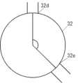
図6Aは、残滓フィルタ9の断面図である。メッシュフィルタ32は、残滓を捕捉するためのメッシュ部材32aと、メッシュフィルタ32の内側を洗浄するための洗浄水を流すためのフィルタ洗浄流路32bと、フィルタ洗浄流路32bを流れる洗浄水をメッシュ部材32aに向けて吐出するための吐出口32cと、フィルタ洗浄流路32bに洗浄水を導入するための導水口32dとを有する。Figure 6A is a cross-sectional view of the residue filter 9. The
導水口32dは、メッシュフィルタ32の側面に設けられる。フィルタ洗浄流路32bは、メッシュフィルタ32の上部の、メッシュ部材32aよりも上方に設けられる。吐出口32cは、フィルタ洗浄流路32bの下面の、メッシュ部材32aが設けられた位置に設けられる。本実施の形態においては、メッシュ部材32aは円筒の全周にわたって設けられるので、吐出口32cも全周にわたって設けられる。The
導水口32dからフィルタ洗浄流路32bに導入された洗浄水が、複数の吐出口32cからメッシュ部材32aに向けて吐出されることにより、メッシュ部材32aの内側に捕捉された残滓を削ぎ落とすことができる。The cleaning water introduced into the filter cleaning flow path 32b from the
残滓フィルタ9を洗浄するための洗浄水として、給水部4から供給される水道水を利用してもよいが、本実施の形態においては、洗い工程やすすぎ工程において使用され、洗浄槽2内に残っている洗浄水を洗浄ポンプ3bにより導水口32dからフィルタ洗浄流路32bに導水する。そのため、食器洗い機は、洗浄ポンプ3bから送られる洗浄水を洗浄ノズル3cと導水口32dの間で分水するための分水器を備える。分水器の詳細については後述する。Although tap water supplied from the water supply unit 4 may be used as the washing water for washing the residue filter 9, in this embodiment, the washing water used in the washing and rinsing processes and remaining in the washing tank 2 is guided from the
導水口32dをフィルタ洗浄流路32bの近傍の側面に設けることにより、導水口32dからフィルタ洗浄流路32bに至る流路を短くすることができるので、圧力損失を抑えることができる。これにより、吐出口32cから洗浄水を吐出する圧力を高めることができるので、メッシュ部材32aの洗浄効率を高めることができる。また、使用者が洗浄槽2の内部を見たときに、導水口32d付近に残っている洗浄水が見えにくいようにすることができる。By providing the
図6Bは、残滓フィルタ9の別の例の断面図である。図6Aに示した例では、導水口32dが残滓フィルタ9の側面に設けられたが、図6Bに示す例では、導水口32dが残滓フィルタ9の底部に設けられる。この場合も、導水口32dからフィルタ洗浄流路32bに導入された洗浄水が、複数の吐出口32cからメッシュ部材32aに向けて吐出されることにより、メッシュ部材32aの内側に捕捉された残滓を削ぎ落とすことができる。Figure 6B is a cross-sectional view of another example of the residue filter 9. In the example shown in Figure 6A, the
洗い工程やすすぎ工程の初期においては、図7Aに示すように、メッシュフィルタ32のメッシュ部材32aのうち、捕捉された残滓によって閉塞された部分の面積は小さいので、メッシュフィルタ32の抵抗は小さい。したがって、洗浄水に含まれる残滓の大部分は、図7Aにおいて実線矢印で示すように、メッシュフィルタ32の内側に流れ込んでメッシュ部材32aにより捕捉される。残滓が取り除かれた洗浄水は、循環水路吸込口32eから循環水路3aに吸い込まれ、洗浄ポンプ3bにより循環される。In the early stages of the washing and rinsing processes, as shown in FIG. 7A, the area of the mesh member 32a of the
洗い工程やすすぎ工程の中期においては、図7Bに示すように、循環水路吸込口32eに近いメッシュ部材32aに、捕捉された残滓が蓄積され、残滓によって閉塞された部分の面積が次第に大きくなるので、メッシュフィルタ32の抵抗が大きくなる。したがって、洗浄水に含まれる残滓の一部は、図7Bにおいて破線矢印で示すように、メッシュフィルタ32の外側のパンチングフィルタ31のパンチング孔や各構成の隙間などから循環水路3aに吸い込まれる。In the middle of the washing and rinsing steps, as shown in FIG. 7B, the captured residue accumulates in the mesh member 32a close to the circulating water
洗い工程やすすぎ工程の後期においては、図7Cに示すように、メッシュ部材32aのより大きい面積が残滓によって閉塞されうる。循環水路3aに残滓が吸い込まれたとしても、その残滓が循環している間にメッシュフィルタ32の内側に流れ込んでメッシュ部材32aにより捕捉されればよいが、循環している間にメッシュ部材32aによって捕捉されず、運転終了時に洗浄槽2の内部に残った残滓は、被洗浄物13に再付着する可能性がある。In the later stages of the washing and rinsing processes, as shown in FIG. 7C, a larger area of the mesh member 32a may become clogged with residue. Even if residue is sucked into the circulation water channel 3a, it is sufficient if the residue flows inside the
洗い工程やすすぎ工程が終了した後、洗浄水を排水ポンプ7bにより排出する際に、残滓フィルタ9により捕捉された残滓の一部は洗浄水とともに排出される。しかし、とくに循環水路吸込口32eに近い位置において、捕捉された残滓が洗浄ポンプ3bによる水圧によってメッシュ部材32aに押し付けられ、メッシュ部材32aに強く付着している場合は、洗浄水を排出してもメッシュ部材32aの内側に残滓が残る場合がある。メッシュ部材32aの多くが残滓により閉塞されたまま次の工程にうつると、工程の初期から図7Bまたは図7Cに示すように残滓が残滓フィルタ9の外側を循環することになるので、運転終了時に残滓が洗浄槽2の内部に残ったままになりやすい。After the washing and rinsing processes are completed, when the cleaning water is discharged by the drain pump 7b, some of the residue captured by the residue filter 9 is discharged together with the cleaning water. However, if the captured residue is pressed against the mesh member 32a by the water pressure of the cleaning pump 3b and adheres strongly to the mesh member 32a, especially near the circulating water
本実施の形態においては、洗浄水を排水する際に、吐出口32cから洗浄水を吐出することにより、メッシュ部材32aの内側に捕捉された残滓を削ぎ落とし、洗浄水とともに食器洗い機の外部に排出する。これにより、次の工程において、図7Aに示すように残滓が残滓フィルタ9の内側に流入しやすくすることができるので、洗浄槽2内に残留していた残滓を残滓フィルタ9により捕捉することができる。したがって、運転終了時に洗浄槽2内に残る残滓の量をより低減させることができるので、残滓が被洗浄物13に再付着するのを抑えることができる。また、残滓フィルタ9に残る残滓の量も低減させることができるので、食器洗い機を衛生的に保ち、臭いや雑菌の増殖などを抑えることができる。In this embodiment, when the washing water is drained, the washing water is discharged from the discharge port 32c, scraping off the residue trapped inside the mesh member 32a and discharging it to the outside of the dishwasher together with the washing water. This makes it easier for the residue to flow into the residue filter 9 in the next step as shown in FIG. 7A, so that the residue remaining in the washing tank 2 can be captured by the residue filter 9. Therefore, the amount of residue remaining in the washing tank 2 at the end of operation can be further reduced, and the residue can be prevented from reattaching to the objects to be washed 13. In addition, the amount of residue remaining in the residue filter 9 can be reduced, so that the dishwasher can be kept hygienic and odors and the growth of bacteria can be suppressed.
洗浄水の排出中に残滓フィルタ9を洗浄する場合、図8Aに示すように、洗浄槽2内の洗浄水の水位33が吐出口32cよりも高いときに吐出口32cから洗浄水を吐出するのが好ましい。洗浄水を水中で吐出することにより、気泡の発生を抑えることができるので、洗浄ポンプ3bに気泡が混入することによる不具合(エア噛み)を抑えることができる。また、洗浄水を水中で吐出することにより、より広範囲に水勢を到達させることができるので、洗浄性能を向上させることができる。また、洗浄水を水中で吐出することにより、水面で水しぶきが上がるのを抑えることができるので、残滓の巻上げを低減し、洗浄効率を向上させることができる。When cleaning the residue filter 9 while the cleaning water is being discharged, it is preferable to discharge the cleaning water from the discharge port 32c when the water level 33 of the cleaning water in the cleaning tank 2 is higher than the discharge port 32c, as shown in FIG. 8A. Discharging the cleaning water underwater can suppress the generation of air bubbles, thereby suppressing problems caused by air bubbles getting into the cleaning pump 3b (air entrapment). Discharging the cleaning water underwater can also make the water pressure reach a wider area, improving the cleaning performance. Discharging the cleaning water underwater can also suppress splashes on the water surface, reducing the stirring up of residue and improving cleaning efficiency.
排水が進み、図8Bに示すように、水位33が吐出口32cより低くなっても、吐出口32cからの洗浄水の吐出を継続してもよい。残滓フィルタ9の上部に付着していた残滓は、排水の初期において削ぎ落とされているので、水位33が吐出口32cより低くなったときに吐出口32cから洗浄水を吐出しても、残滓フィルタ9の上部に付着していた残滓が飛び散る不具合はない。As the drainage progresses, even if the water level 33 becomes lower than the outlet 32c as shown in FIG. 8B, the discharge of cleaning water from the outlet 32c may continue. Since the residue adhering to the upper part of the residue filter 9 is scraped off in the early stages of drainage, even if the cleaning water is discharged from the outlet 32c when the water level 33 becomes lower than the outlet 32c, there is no problem in that the residue adhering to the upper part of the residue filter 9 is scattered.
さらに排水が進み、図8Cに示すように、水位33が循環水路吸込口32eより低くなる前に、残滓フィルタ9の洗浄を終了する。上述したように、残滓フィルタ9の洗浄中には、洗浄ポンプ3bが駆動され、循環水路吸込口32eから吸い込まれた洗浄水が洗浄ポンプ3bによりメッシュフィルタ32のフィルタ洗浄流路32bに導水されるので、水位33が循環水路吸込口32eより低くなると、洗浄ポンプ3bに空気が吸い込まれて不具合(エア噛み)が生じる。したがって、水位33が循環水路吸込口32eより低くなる前に洗浄ポンプ3bを停止して残滓フィルタ9の洗浄を終了する。As the water continues to be discharged, the cleaning of the residue filter 9 is terminated before the water level 33 becomes lower than the circulation water
洗い工程およびすすぎ工程において、洗浄ポンプ3bにより洗浄水が循環されるので、図7Bおよび図7Cに示したように、循環水路吸込口32eの近傍のメッシュ部材32aの内側に残滓が蓄積されやすい。図9Aに示すように、導水口32dが循環水路吸込口32eの近傍にあると、循環水路吸込口32eの近傍のメッシュ部材32aが残滓により閉塞されたときに、吐出口32cから導水口32dを経由してメッシュ部材32aの外側から循環水路吸込口32eに洗浄水が流れるので、残滓をメッシュ部材32aにより捕捉することができない。したがって、図9Bに示すように、導水口32dを循環水路吸込口32eから離れた位置に配置する。これにより、吐出口32cから導水口32dを経由してメッシュ部材32aの外側から循環水路吸込口32eに至る経路に洗浄水が逃げてしまうのを抑えることができるので、洗浄効率を向上させることができる。導水口32dは、循環水路吸込口32eの近傍に配置されなければよい。例えば、図9Cに示すように、メッシュフィルタ32を上から見たときに、メッシュフィルタ32の中心と導水口32dを結ぶ直線と、メッシュフィルタ32の中心と循環水路吸込口32eを結ぶ直線とのなす角は、45°以上、50°以上、55°以上、60°以上、65°以上、70°以上、75°以上、80°以上、85°以上、90°以上、95°以上、100°以上、110°以上、120°以上、130°以上、140°以上、150°以上、160°以上、170°以上であってもよい。導水口32dは、循環水路吸込口32eに対向する位置に配置されてもよい。In the washing and rinsing steps, the washing water is circulated by the washing pump 3b, so that residues tend to accumulate inside the mesh member 32a near the circulation water
図10Aに示すように、循環水路吸込口32eに近いほど、洗浄水が通過する量が多いので、メッシュ部材32aの内側に残滓が蓄積されやすい。したがって、図10Bに示すように、循環水路吸込口32eに近いほど、吐出口32cの数または面積を多くして、より多くの洗浄水をメッシュ部材32aに向けて吐出する。これにより、洗浄性能を向上させることができる。As shown in FIG. 10A, the closer to the
図11に示すように、メッシュ部材32aの内側面に対して鋭角に吐出口32cから洗浄水を吐出することにより、メッシュ部材32aの内側に付着した残滓をより効果的に削ぎ落とすことができる。したがって、吐出口32cから洗浄水を吐出する角度は、メッシュ部材32aの内側面に対して、40°以下、30°以下、20°以下、10°以下、9°以下、8°以下、7°以下、6°以下、5°以下、4°以下、3°以下、2°以下、1°以下であってもよい。As shown in FIG. 11, by ejecting cleaning water from outlet 32c at an acute angle with respect to the inner surface of mesh member 32a, residues adhering to the inside of mesh member 32a can be scraped off more effectively. Therefore, the angle at which cleaning water is ejected from outlet 32c with respect to the inner surface of mesh member 32a may be 40° or less, 30° or less, 20° or less, 10° or less, 9° or less, 8° or less, 7° or less, 6° or less, 5° or less, 4° or less, 3° or less, 2° or less, or 1° or less.
図6Aに示すように、導水口32dをメッシュフィルタ32の側面に設ける場合、メッシュフィルタ32を水溜部8に設置する際に、洗浄ポンプ3bから導水口32dに至るフィルタ流路と導水口32dとが接続されるように、メッシュフィルタ32を位置決めをする必要がある。本実施の形態においては、図12Aに示すように、メッシュフィルタ32の側面に突出する導水口32dと嵌合する嵌合部34が水溜部8に設けられる。嵌合部34は、導水口32dの外周に嵌合するC字型のリブである。メッシュフィルタ32を水溜部8に設置する際には、図12Bに示すように、メッシュフィルタ32を水溜部8に挿入した後、メッシュフィルタ32を回転させる。図12Cに示すように、導水口32dと嵌合部34とが嵌合することにより、フィルタ流路と導水口32dが接続された位置でメッシュフィルタ32が位置決めされる。このとき、導水口32dの外側面に設けられたストッパー32fが嵌合部34に当接することにより、メッシュフィルタ32の過度な回転が抑えられる。また、嵌合部34は、弾性を有する材料により構成されており、導水口32dを外側から締め付けるように付勢されているので、メッシュフィルタ32の逆方向への回転が抑えられる。これにより、フィルタ流路と導水口32dとが接続された状態で維持することができるので、洗浄水の圧力損失を抑え、洗浄性能を向上させることができる。また、導水口32dの近傍でメッシュフィルタ32を位置決めするので、フィルタ流路と導水口32dとをより精度良く接続することができる。As shown in FIG. 6A, when the
図13に示すように、フィルタ流路35と導水口32dとの間の接続部35aは、二重以上の多層構造を有する。これにより、接続部35aに生じた隙間の抵抗を高め、隙間から洗浄水が漏れるのを抑えることができるので、洗浄水の圧力損失を抑え、洗浄性能を向上させることができる。As shown in FIG. 13, the connection 35a between the filter flow path 35 and the
図14は、洗浄ポンプ3bから送られる洗浄水を洗浄ノズル3cに導水する洗浄ノズル流路37とフィルタ流路35との間で分水する分水器38の例を示す。分水器38は、洗浄ポンプ3bから送られる洗浄水の流路36の途中に設けられ、洗浄ノズル流路37を開いてフィルタ流路35を閉じる状態と、洗浄ノズル流路37を閉じてフィルタ流路35を開く状態との間で切り替える。分水器38は、洗浄ノズル流路37とフィルタ流路35との間で摺動する面材であってもよいし、弁などであってもよい。分水器38の状態は、制御部17により制御される。Figure 14 shows an example of a water distributor 38 that distributes water between the cleaning nozzle flow path 37, which guides the cleaning water sent from the cleaning pump 3b to the cleaning nozzle 3c, and the filter flow path 35. The water distributor 38 is provided midway along the flow path 36 of the cleaning water sent from the cleaning pump 3b, and switches between a state in which the cleaning nozzle flow path 37 is open and the filter flow path 35 is closed, and a state in which the cleaning nozzle flow path 37 is closed and the filter flow path 35 is open. The water distributor 38 may be a surface material that slides between the cleaning nozzle flow path 37 and the filter flow path 35, or may be a valve. The state of the water distributor 38 is controlled by the control unit 17.
[1-2.動作]
以上のように構成された食器洗い機について、以下その動作、作用を説明する。 [1-2. Operation]
The operation and function of the dishwasher constructed as above will now be described.
まず、使用者は、扉体5のハンドル5aを把持して食器洗い機の筐体1から洗浄槽2を引き出す。このとき、内蓋10は、洗浄槽2の引き出し動作に連動してリンク機構11により上昇し、上面開口部2aから離れる。次に、使用者は、洗浄槽2の上面開口部2aから食器などの被洗浄物13を食器かご6にセットする。そして、所定量の洗剤を、洗浄槽2内の洗剤供給装置(図示せず)に投入する。つぎに、使用者は、洗浄槽2を筐体1内に押し込んで扉体5を閉じる。このとき、内蓋10は、洗浄槽2の押し込み動作に連動してリンク機構11により下降し、シール部12を圧縮して上面開口部2aが密閉される。First, the user grasps the handle 5a of the door body 5 and pulls out the washing tub 2 from the housing 1 of the dishwasher. At this time, the inner lid 10 rises by the link mechanism 11 in conjunction with the pulling out operation of the washing tub 2, and moves away from the top opening 2a. Next, the user places the items to be washed 13, such as dishes, in the dish basket 6 through the top opening 2a of the washing tub 2. Then, a predetermined amount of detergent is poured into the detergent supply device (not shown) in the washing tub 2. Next, the user pushes the washing tub 2 into the housing 1 and closes the door body 5. At this time, the inner lid 10 descends by the link mechanism 11 in conjunction with the pushing in operation of the washing tub 2, compressing the seal portion 12 and sealing the top opening 2a.
使用者は、制御部17に接続された操作部(図示せず)で、運転コースを設定した後、開始ボタン(図示せず)を操作して、洗浄運転を開始する。これにより、制御部17は、運転コースに基づいて、洗浄運転を実行する。制御部17は、洗い工程、すすぎ工程および乾燥工程を、以下で説明する方法により、順番に実行する。The user sets the operation course on the operation unit (not shown) connected to the control unit 17, and then operates the start button (not shown) to start the cleaning operation. This causes the control unit 17 to execute the cleaning operation based on the operation course. The control unit 17 executes the washing process, rinsing process, and drying process in sequence using the method described below.
まず、洗浄運転の洗い工程について、説明する。制御部17は、はじめに、給水弁4bを動作させて洗浄槽2に給水するように給水弁4bを制御し、所定量の洗浄水を洗浄槽2に供給する。給水が完了すると、洗剤供給装置(図示せず)により洗剤が投入される。そして、洗浄ポンプ3bを駆動して洗浄水を圧送し、洗浄槽底部2bに配設された洗浄ノズル3cから洗浄水を噴射し、洗浄水を循環させる。制御部17は、洗浄水を循環させながらヒータ(図示せず)に通電し、洗浄水を加熱する。このとき、制御部17は、温度センサ(図示せず)により洗浄槽底部2bの壁を介して、洗浄水の温度を検知する。そして、制御部17は、洗浄水が所定温度となるように制御する。First, the washing process of the washing operation will be described. First, the control unit 17 operates the water supply valve 4b to control the water supply valve 4b to supply water to the washing tank 2, and supplies a predetermined amount of washing water to the washing tank 2. When the water supply is completed, detergent is added by a detergent supply device (not shown). Then, the washing pump 3b is driven to pump the washing water, and the washing water is sprayed from the washing nozzle 3c arranged on the bottom part 2b of the washing tank, and the washing water is circulated. While circulating the washing water, the control unit 17 energizes the heater (not shown) to heat the washing water. At this time, the control unit 17 detects the temperature of the washing water through the wall of the bottom part 2b of the washing tank using a temperature sensor (not shown). Then, the control unit 17 controls the washing water to be at a predetermined temperature.
噴射された洗浄水は、被洗浄物13の汚れを洗浄し、残滓フィルタ9と水溜部8を通過して、再度、洗浄ポンプ3bに吸い込まれる。このとき、洗浄水に含まれる残滓は、残滓フィルタ9に捕捉される。洗浄ポンプ3bは、吸い込んだ洗浄水を圧送し、洗浄ノズル3cに洗浄水を供給する。つまり、洗浄水は、上記のように循環して、被洗浄物13を洗浄する。制御部17は、上記のような循環動作を所定時間(例えば、30分)だけ行う。The sprayed cleaning water cleans the dirt from the object to be cleaned 13, passes through the residue filter 9 and the water reservoir 8, and is sucked back into the cleaning pump 3b. At this time, the residue contained in the cleaning water is captured by the residue filter 9. The cleaning pump 3b pumps the sucked cleaning water and supplies it to the cleaning nozzle 3c. In other words, the cleaning water circulates as described above to clean the object to be cleaned 13. The control unit 17 performs the above-mentioned circulation operation for a predetermined time (e.g., 30 minutes).
制御部17は、循環動作を終了すると、汚れを含む洗浄水を筐体1外に排出する。このとき、残滓フィルタ9に捕捉された残滓は、洗浄水とともに筐体1外に排出される。そして、制御部17は、洗い工程を終了するとともにすすぎ工程を開始し、新たに洗浄水を、洗浄槽2内に供給する。When the control unit 17 finishes the circulation operation, it discharges the cleaning water containing dirt out of the housing 1. At this time, the residue captured in the residue filter 9 is discharged out of the housing 1 together with the cleaning water. Then, the control unit 17 finishes the washing process and starts the rinsing process, supplying new cleaning water into the cleaning tank 2.
つぎに、制御部17は、洗い工程と同様に、洗浄ポンプ3bを運転し、洗浄ノズル3cから新しい洗浄水を、被洗浄物13に向けて噴射する。そして、洗浄水で、残留する洗剤および残滓などを、被洗浄物13から洗い流す。このとき、制御部17は、洗浄水の排出、洗浄水の供給などの動作を、複数回(例えば、2回~3回)繰り返して実行し、すすぎ工程を行う。特に最後のすすぎ動作において、洗浄水を高温に加熱する加熱すすぎを行う。これにより、被洗浄物13および洗浄槽2内部が高温に加熱され、乾燥工程での水分蒸発が促進される。Next, the control unit 17 operates the cleaning pump 3b, as in the washing process, and sprays new cleaning water from the cleaning nozzle 3c towards the object 13 to be cleaned. The cleaning water is then used to wash away any remaining detergent and residue from the object 13 to be cleaned. At this time, the control unit 17 repeats operations such as draining the cleaning water and supplying the cleaning water multiple times (e.g., two to three times) to perform the rinsing process. In particular, in the final rinsing operation, a heated rinse is performed in which the cleaning water is heated to a high temperature. This heats the object 13 to the inside of the cleaning tank 2 to a high temperature, accelerating the evaporation of water in the drying process.
そして、制御部17は、すすぎ工程が終了すると、乾燥工程を行う。制御部17は、送風ファン(図示せず)およびヒータ(図示せず)を制御し、洗浄槽2内に導入される空気を加熱しながら連通通路(図示せず)を通じて洗浄槽2内の湿潤空気を排出し、被洗浄物13を乾燥させる。制御部17は、乾燥工程を所定時間(例えば、30分)行ったのち、食器洗い機の洗浄運転を終了する。Then, when the rinsing process is completed, the control unit 17 performs the drying process. The control unit 17 controls the blower fan (not shown) and heater (not shown) to heat the air introduced into the cleaning tank 2 while discharging the moist air in the cleaning tank 2 through a communication passage (not shown), thereby drying the items 13 to be cleaned. After performing the drying process for a predetermined time (e.g., 30 minutes), the control unit 17 ends the cleaning operation of the dishwasher.
図15は、洗い工程またはすすぎ工程における1回の洗浄動作またはすすぎ動作の詳細を示すフローチャートである。図16は、1回の洗浄動作またはすすぎ動作における各構成の状態を示すタイミングチャートである。Figure 15 is a flow chart showing the details of one cleaning or rinsing operation in the washing or rinsing process. Figure 16 is a timing chart showing the state of each component in one cleaning or rinsing operation.
制御部17は、給水弁4bをオンにし(S10)、所定量の水が洗浄槽2内に供給されるまで(S12のN)、水道水を洗浄槽2内に導入する。所定量の水が洗浄槽2内に供給されると(S12のY)、制御部17は、洗浄ポンプ3bをオンにし(S14)、所定時間が経過するまで(S16のN)、洗浄ノズル3cから洗浄水を噴射して被洗浄物13を洗浄する。洗い工程と加熱すすぎ工程においては、制御部17は、ヒータをオンにする。所定時間が経過すると(S16のY)、制御部17は、洗浄ポンプ3bをオフにする(S18)。以上で、庫内洗浄工程を終了する。The control unit 17 turns on the water supply valve 4b (S10) and introduces tap water into the cleaning tank 2 until a predetermined amount of water is supplied into the cleaning tank 2 (N in S12). When a predetermined amount of water has been supplied into the cleaning tank 2 (Y in S12), the control unit 17 turns on the cleaning pump 3b (S14) and sprays cleaning water from the cleaning nozzle 3c to clean the object 13 until a predetermined time has elapsed (N in S16). In the washing process and the heated rinsing process, the control unit 17 turns on the heater. When the predetermined time has elapsed (Y in S16), the control unit 17 turns off the cleaning pump 3b (S18). This completes the interior cleaning process.
制御部17は、分水器38をオンにし(S20)、洗浄ノズル流路37が閉じられ、フィルタ流路35が開かれるまで(S22のN)、分水器38を駆動する。洗浄ポンプ3bからの流路がフィルタ流路35に切り替えられると(S22のY)、制御部17は、分水器38をオフにし、排水ポンプ7bをオンにして排水を開始する(S24)。つづいて、制御部17は、洗浄ポンプ3bをオンにして(S26)、所定時間が経過するまで(S28のN)、洗浄水を吐出口32cからメッシュ部材32aに向けて吐出し、メッシュ部材32aに付着していた残滓を洗浄水とともに外部に排出させる。洗浄水の水位が吐出口32cより低くなるまでの時間として予め設定された所定時間が経過すると(S28のY)、制御部17は、洗浄ポンプ3bをオフにして(S30)、残滓フィルタ9の洗浄を終了する。洗浄槽2内の洗浄水を外部に排出するための時間として予め設定された時間が経過すると、制御部17は、排水ポンプ7bをオフにして(S32)、排水を終了する。制御部17は、分水器38をオンにし(S34)、洗浄ノズル流路37が開かれ、フィルタ流路35が閉じられるまで(S36のN)、分水器を駆動する。洗浄ポンプ3bからの流路が洗浄ノズル流路37に切り替えられると(S36のY)、フィルタ洗浄工程を終了し、1回の洗浄またはすすぎ動作を終了する。The control unit 17 turns on the water distributor 38 (S20) and drives the water distributor 38 until the cleaning nozzle flow path 37 is closed and the filter flow path 35 is opened (N in S22). When the flow path from the cleaning pump 3b is switched to the filter flow path 35 (Y in S22), the control unit 17 turns off the water distributor 38 and turns on the drain pump 7b to start draining (S24). Next, the control unit 17 turns on the cleaning pump 3b (S26) and discharges the cleaning water from the outlet 32c toward the mesh member 32a until a predetermined time has elapsed (N in S28), and discharges the residue attached to the mesh member 32a to the outside together with the cleaning water. When a predetermined time has elapsed (Y in S28) that is preset as the time until the water level of the cleaning water becomes lower than the outlet 32c, the control unit 17 turns off the cleaning pump 3b (S30) and ends the cleaning of the residue filter 9. When a preset time has elapsed for discharging the cleaning water in the cleaning tank 2 to the outside, the control unit 17 turns off the drain pump 7b (S32) and ends the drainage. The control unit 17 turns on the water distributor 38 (S34) and drives the water distributor until the cleaning nozzle flow path 37 is opened and the filter flow path 35 is closed (N in S36). When the flow path from the cleaning pump 3b is switched to the cleaning nozzle flow path 37 (Y in S36), the filter cleaning process ends and one cleaning or rinsing operation is completed.
加熱すすぎの開始時に、リンス剤が洗浄槽2内に投入されてもよい。これにより、水の接触角を小さくすることができるので、乾燥工程での水分蒸発がさらに促進される。また、加熱すすぎの後の排水中にフィルタ洗浄工程を実行することにより、洗浄水に含まれるリンス剤でフィルタ洗浄流路32bやフィルタ流路35をコーティングすることができるので、これらの流路の乾燥も促進することができ、衛生面を向上させることができる。加熱すすぎが実行されるまでの洗い工程やすすぎ工程において、ほとんどの残滓は外部に排出されるので、加熱すすぎ中または加熱すすぎ後に、洗浄水を排水せずに洗浄ポンプ3bを駆動してフィルタ洗浄工程を実行してもよい。これにより、メッシュフィルタ32などに付着した油成分などの汚れを効率良く除去することができる。At the start of the heated rinse, a rinse agent may be added to the cleaning tank 2. This reduces the contact angle of water, further accelerating the evaporation of water during the drying process. In addition, by performing the filter cleaning process during the drainage after the heated rinse, the filter cleaning flow path 32b and the filter flow path 35 can be coated with the rinse agent contained in the cleaning water, which also accelerates the drying of these flow paths and improves hygiene. Since most of the residue is discharged to the outside during the washing process and rinsing process before the heated rinse is performed, the filter cleaning process may be performed by driving the cleaning pump 3b during or after the heated rinse without draining the cleaning water. This allows for efficient removal of dirt such as oil components attached to the
[1-3.効果等]
以上のように、本実施の形態において、食器洗い機は、筐体1と、筐体1内に設けられ被洗浄物13を収容する洗浄槽2と、洗浄槽2の底部に設けられる水溜部8と、水溜部8に設置され水溜部8に流入する洗浄水に含まれる残滓を捕捉する残滓フィルタ9と、水溜部8と筐体1の外部とを連通する排水路7aと、残滓フィルタ9により捕捉された残滓を洗い流すための洗浄水を残滓フィルタ9に向けて吐出する吐出口32cと、を備え、洗浄槽2の内部の洗浄水が排水路7aを介して筐体1外に排出されるときに、残滓フィルタ9に捕捉されていた残滓が洗浄水と共に排出されるように構成され、洗浄槽2の内部の洗浄水の水位が吐出口32cより高いときに吐出口32cから洗浄水が残滓フィルタ9に向けて吐出される。これにより、気泡の発生を抑えることができるので、洗浄ポンプ3bに気泡が混入することによる不具合(エア噛み)を抑えることができる。また、より広範囲に水勢を到達させることができるので、洗浄性能を向上させることができる。また、水面で水しぶきが上がるのを抑えることができるので、残滓の巻上げを低減し、洗浄効率を向上させることができる。 [1-3. Effects, etc.]
As described above, in this embodiment, the dishwasher includes the housing 1, the washing tank 2 that is provided in the housing 1 and that contains the object 13 to be washed, the water reservoir 8 that is provided at the bottom of the washing tank 2, the residue filter 9 that is installed in the water reservoir 8 and captures residues contained in the washing water that flows into the water reservoir 8, the drainage channel 7a that connects the water reservoir 8 to the outside of the housing 1, and the outlet 32c that discharges washing water to wash away the residues captured by the residue filter 9 toward the residue filter 9. When the washing water inside the washing tank 2 is discharged outside the housing 1 through the drainage channel 7a, the residues captured by the residue filter 9 are discharged together with the washing water, and when the water level of the washing water inside the washing tank 2 is higher than the outlet 32c, the washing water is discharged from the outlet 32c toward the residue filter 9. This makes it possible to suppress the generation of air bubbles, thereby suppressing problems (air entrapment) caused by air bubbles being mixed into the washing pump 3b. In addition, the water pressure can be directed over a wider area, improving cleaning performance. Also, the amount of splashing water on the water surface can be reduced, reducing the amount of residue stirred up and improving cleaning efficiency.
また、本実施の形態において、食器洗い機は、水溜部8に流入した洗浄水を洗浄槽2に循環させるための洗浄ポンプ3bを備え、洗浄ポンプ3bに洗浄水を吸い込むための循環水路吸込口32eに近いほど、吐出口32cの数または面積が大きい。これにより、洗浄効率を向上させることができる。In addition, in this embodiment, the dishwasher is equipped with a washing pump 3b for circulating the washing water that has flowed into the water reservoir 8 to the washing tank 2, and the number or area of the discharge ports 32c is larger the closer they are to the circulation water
また、本実施の形態において、残滓フィルタ9は、残滓フィルタ9の外側に突出するように設けられ吐出口32cに洗浄水を導水するための導水口32dを備え、食器洗い機は、導水口32dと嵌合することにより残滓フィルタ9を位置決めするための嵌合部34を備える。これにより、洗浄水の圧力損失を抑えることができるので、洗浄効率を向上させることができる。In addition, in this embodiment, the residue filter 9 has a
また、本実施の形態において、残滓フィルタ9は、残滓フィルタ9の底部に設けられ吐出口32cに洗浄水を導水するための導水口32dを備える。これにより、洗浄効率を向上させることができる。In addition, in this embodiment, the residue filter 9 is provided with a
また、本実施の形態において、上記の食器洗い機を制御する方法は、洗浄槽2に洗浄水を給水して被洗浄物13を洗浄するステップと、洗浄するステップの終了後に洗浄水を排水するステップと、排水するステップにおいて、洗浄槽2の内部の水位が吐出口32cより高いときに、洗浄水を吐出口32cから吐出するステップと、を備える。これにより、気泡の発生を抑えることができるので、洗浄ポンプ3bに気泡が混入することによる不具合(エア噛み)を抑えることができる。また、より広範囲に水勢を到達させることができるので、洗浄性能を向上させることができる。また、水面で水しぶきが上がるのを抑えることができるので、残滓の巻上げを低減し、洗浄効率を向上させることができる。In this embodiment, the method of controlling the dishwasher includes the steps of supplying washing water to the washing tank 2 to wash the object 13, draining the washing water after the washing step, and discharging the washing water from the discharge port 32c when the water level inside the washing tank 2 is higher than the discharge port 32c during the draining step. This makes it possible to suppress the generation of air bubbles, thereby suppressing problems (air entrapment) caused by air bubbles being mixed into the washing pump 3b. In addition, the water pressure can be made to reach a wider area, thereby improving the washing performance. In addition, it is possible to suppress water splashes on the water surface, thereby reducing the stirring up of residue and improving washing efficiency.
(他の実施の形態)
以上のように、本出願において開示する技術の例示として、実施の形態1を説明した。しかしながら、本開示における技術は、これに限定されず、変更、置き換え、付加、省略などを行った実施の形態にも適用できる。また、上記実施の形態1で説明した各構成要素を組み合わせて、新たな実施の形態とすることも可能である。 Other Embodiments
As described above, the first embodiment has been described as an example of the technology disclosed in the present application. However, the technology in the present disclosure is not limited to this, and can be applied to embodiments in which modifications, substitutions, additions, omissions, etc. are made. In addition, it is also possible to combine the components described in the first embodiment to create a new embodiment.
そこで、以下、他の実施の形態を例示する。Therefore, other embodiments are given below as examples.
実施の形態1では、ビルトイン型の食器洗い機について説明したが、実施の形態1の技術は、卓上型の食器洗い機にも同様に適用可能である。In the first embodiment, a built-in dishwasher is described, but the technology of the first embodiment can be similarly applied to a countertop dishwasher.
実施の形態1では、食器洗い機の運転中、洗い工程やすすぎ工程における排水中にフィルタ洗浄を実行したが、被洗浄物13を洗浄するための運転コースの他に、残滓フィルタ9を洗浄するための専用の運転コースが設けられてもよい。この場合、実施の形態1と同様に洗浄水が洗浄槽2内に給水されてもよいし、給水路4aから直接メッシュフィルタ32のフィルタ洗浄流路32bに水道水が導水されてもよい。また、洗剤が洗浄槽2内に自動的に投入されてもよい。In the first embodiment, filter cleaning is performed during drainage in the washing and rinsing processes while the dishwasher is in operation, but in addition to the operating course for cleaning the items to be cleaned 13, a dedicated operating course for cleaning the residue filter 9 may be provided. In this case, cleaning water may be supplied to the cleaning tank 2 as in the first embodiment, or tap water may be introduced directly from the water supply passage 4a to the filter cleaning flow passage 32b of the
なお、上述の実施の形態は、本開示における技術を例示するためのものであるから、特許請求の範囲またはその均等の範囲において種々の変更、置き換え、付加、省略などを行うことができる。The above-described embodiments are intended to illustrate the technology disclosed herein, and various modifications, substitutions, additions, omissions, etc. may be made within the scope of the claims or their equivalents.
本開示は、食器洗い機に利用可能である。This disclosure can be used in dishwashers.
1 筐体
1a 前面開口部
2 洗浄槽
2a 上面開口部
2b 洗浄槽底部
3 洗浄装置
3a 循環水路
3b 洗浄ポンプ
3c 洗浄ノズル
4 給水部
4a 給水路
4b 給水弁
5 扉体
6 食器かご
7 排水部
7a 排水路
7b 排水ポンプ
7c 排水口
8 水溜部
9 残滓フィルタ
9c メッシュ部
10 内蓋
11 リンク機構
12 シール部
13 被洗浄物
14 注水部
14a 注水口
17 制御部
20 案内部
20a 壁面
20b 流路
20c 吐出口
21 循環部
21a 循環路
21b 循環ポンプ
30 格子フィルタ
31 パンチングフィルタ
32 メッシュフィルタ
32a メッシュ部材
32b フィルタ洗浄流路
32c 吐出口
32d 導水口
32e 循環水路吸込口
32f ストッパー
33 水位
34 嵌合部
35 フィルタ流路
35a 接続部
36 流路
37 洗浄ノズル流路
38 分水器 LIST OF SYMBOLS 1 Housing 1a Front opening 2 Washing tank 2a Top opening 2b Washing tank bottom 3 Washing device 3a Circulating water channel 3b Washing pump 3c Washing nozzle 4 Water supply section 4a Water supply channel 4b Water supply valve 5 Door body 6 Dish basket 7 Drain section 7a Drain channel 7b Drain pump 7c Drain outlet 8 Water reservoir section 9 Residue filter 9c Mesh section 10 Inner lid 11 Link mechanism 12 Sealing section 13 Object to be washed 14 Water injection section 14a Water injection port 17 Control section 20 Guide section 20a Wall surface 20b Flow path 20c Discharge port 21 Circulation section 21a Circulation channel 21b Circulation pump 30 Lattice filter 31
Claims (5)
Translated fromJapanese前記筐体内に設けられ被洗浄物を収容する洗浄槽と、
前記洗浄槽の底部に設けられる水溜部と、
前記水溜部に設置され前記水溜部に流入する洗浄水に含まれる残滓を捕捉する残滓フィルタと、
前記水溜部と前記筐体の外部とを連通する排水路と、
前記残滓フィルタにより捕捉された残滓を洗い流すための洗浄水を前記残滓フィルタに向けて吐出する吐出口と、
を備え、
前記洗浄槽の内部の洗浄水が前記排水路を介して前記筐体外に排出されるときに、前記残滓フィルタに捕捉されていた残滓が洗浄水と共に排出されるように構成され、
前記洗浄槽の内部の洗浄水の水位が前記吐出口より高いときに前記吐出口から洗浄水が前記残滓フィルタに向けて吐出される
食器洗い機。 A housing and
A cleaning tank provided in the housing and configured to accommodate an object to be cleaned;
a water reservoir provided at the bottom of the cleaning tank;
a residue filter disposed in the water reservoir and configured to capture residue contained in the cleaning water flowing into the water reservoir;
a drainage channel that communicates the water reservoir with the outside of the housing;
a discharge port for discharging cleaning water toward the residue filter to wash away the residue captured by the residue filter;
Equipped with
When the cleaning water in the cleaning tank is discharged to the outside of the housing through the drainage channel, the residue captured in the residue filter is discharged together with the cleaning water,
When the water level of the washing water in the washing tub is higher than the discharge outlet, the washing water is discharged from the discharge outlet toward the residue filter.
前記洗浄ポンプに洗浄水を吸い込むための吸込口に近いほど、前記吐出口の数または面積が大きい
請求項1に記載の食器洗い機。 a cleaning pump for circulating the cleaning water flowing into the water reservoir to the cleaning tank;
2. The dishwasher according to claim 1, wherein the number or area of the discharge ports is larger the closer the discharge ports are to a suction port for drawing wash water into the wash pump.
前記導水口と嵌合することにより前記残滓フィルタを位置決めするための嵌合部を備える
請求項1または2に記載の食器洗い機。 the residue filter includes a water guide port that is provided so as to protrude outward from the residue filter and that guides cleaning water to the discharge port;
3. The dishwasher according to claim 1, further comprising a fitting portion for positioning the residue filter by fitting with the water inlet.
請求項1または2に記載の食器洗い機。 3. The dishwasher according to claim 1, wherein the residue filter includes a water inlet provided at a bottom of the residue filter for guiding wash water to the discharge port.
前記洗浄槽に洗浄水を給水して前記被洗浄物を洗浄するステップと、
前記洗浄するステップの終了後に前記洗浄水を排水するステップと、
前記排水するステップにおいて、前記洗浄槽の内部の水位が前記吐出口より高いときに、洗浄水を前記吐出口から吐出するステップと、
を備える制御方法。 A method for controlling a dishwasher according to any one of claims 1 to 4, comprising the steps of:
supplying cleaning water to the cleaning tank to clean the object;
A step of draining the cleaning water after the cleaning step is completed;
a step of discharging cleaning water from the outlet when a water level inside the cleaning tank is higher than the outlet in the draining step;
A control method comprising:
Priority Applications (3)
| Application Number | Priority Date | Filing Date | Title |
|---|---|---|---|
| JP2021097101AJP7588333B2 (en) | 2021-06-10 | 2021-06-10 | Dishwasher and control method |
| CN202111190855.1ACN113892886B (en) | 2021-06-10 | 2021-10-13 | Tableware cleaning machine and control method |
| JP2024190423AJP2025010306A (en) | 2021-06-10 | 2024-10-30 | Control Method |
Applications Claiming Priority (1)
| Application Number | Priority Date | Filing Date | Title |
|---|---|---|---|
| JP2021097101AJP7588333B2 (en) | 2021-06-10 | 2021-06-10 | Dishwasher and control method |
Related Child Applications (1)
| Application Number | Title | Priority Date | Filing Date |
|---|---|---|---|
| JP2024190423ADivisionJP2025010306A (en) | 2021-06-10 | 2024-10-30 | Control Method |
Publications (2)
| Publication Number | Publication Date |
|---|---|
| JP2022188855A JP2022188855A (en) | 2022-12-22 |
| JP7588333B2true JP7588333B2 (en) | 2024-11-22 |
Family
ID=79191625
Family Applications (2)
| Application Number | Title | Priority Date | Filing Date |
|---|---|---|---|
| JP2021097101AActiveJP7588333B2 (en) | 2021-06-10 | 2021-06-10 | Dishwasher and control method |
| JP2024190423APendingJP2025010306A (en) | 2021-06-10 | 2024-10-30 | Control Method |
Family Applications After (1)
| Application Number | Title | Priority Date | Filing Date |
|---|---|---|---|
| JP2024190423APendingJP2025010306A (en) | 2021-06-10 | 2024-10-30 | Control Method |
Country Status (2)
| Country | Link |
|---|---|
| JP (2) | JP7588333B2 (en) |
| CN (1) | CN113892886B (en) |
Families Citing this family (1)
| Publication number | Priority date | Publication date | Assignee | Title |
|---|---|---|---|---|
| CN116458819A (en)* | 2023-03-29 | 2023-07-21 | 宁波方太厨具有限公司 | Cleaning machine |
Citations (1)
| Publication number | Priority date | Publication date | Assignee | Title |
|---|---|---|---|---|
| JP2019205599A (en) | 2018-05-29 | 2019-12-05 | パナソニックIpマネジメント株式会社 | dishwasher |
Family Cites Families (14)
| Publication number | Priority date | Publication date | Assignee | Title |
|---|---|---|---|---|
| US4038103A (en)* | 1976-07-27 | 1977-07-26 | Hobart Corporation | Dishwasher filter flushing system |
| SE459554B (en)* | 1987-11-26 | 1989-07-17 | Asea Cylinda Ab | PROCEDURE FOR SOIL CLEANING OF SILVER SYSTEM BY DISHWASHER AND DISHWASHER WITH ORGAN BEFORE IMPLEMENTATION OF THE PROCEDURE |
| JPH0249626A (en)* | 1988-05-26 | 1990-02-20 | Mitsubishi Electric Corp | Dishwasher |
| JPH04224725A (en)* | 1990-12-26 | 1992-08-14 | Matsushita Electric Ind Co Ltd | dishwasher |
| JPH09248267A (en)* | 1996-03-15 | 1997-09-22 | Sanyo Electric Co Ltd | Automatized dish washing apparatus and dish washing method using the same |
| KR0165044B1 (en)* | 1996-09-24 | 1999-05-01 | 삼성전자주식회사 | dish washer |
| US7472712B2 (en)* | 2003-09-05 | 2009-01-06 | Whirlpool Corporation | Dishwasher filter |
| DE102010063711A1 (en)* | 2010-12-21 | 2012-06-21 | Premark Feg L.L.C. (N.D.Ges.D. Staates Delaware) | Dishwasher with automatic dirt removal |
| JP2013075096A (en)* | 2011-09-30 | 2013-04-25 | Hoshizaki Electric Co Ltd | Dishwasher |
| US9943210B2 (en)* | 2014-05-13 | 2018-04-17 | Illinois Tool Works Inc. | Warewasher with automated scrapping system |
| DE102017202783A1 (en)* | 2017-02-21 | 2018-08-23 | BSH Hausgeräte GmbH | Dishwasher with hydraulic arrangement for cleaning a filter device and method |
| CN108514395B (en)* | 2018-04-04 | 2024-06-25 | 广东美的厨房电器制造有限公司 | Dishwasher and its filter system |
| US10791905B2 (en)* | 2019-02-08 | 2020-10-06 | Haier Us Appliance Solutions, Inc. | Methods for determining operation mode of dishwasher appliance fluid circulation system |
| CN112656331A (en)* | 2020-12-03 | 2021-04-16 | 华帝股份有限公司 | Dish washing machine capable of washing and filtering device |
- 2021
- 2021-06-10JPJP2021097101Apatent/JP7588333B2/enactiveActive
- 2021-10-13CNCN202111190855.1Apatent/CN113892886B/enactiveActive
- 2024
- 2024-10-30JPJP2024190423Apatent/JP2025010306A/enactivePending
Patent Citations (1)
| Publication number | Priority date | Publication date | Assignee | Title |
|---|---|---|---|---|
| JP2019205599A (en) | 2018-05-29 | 2019-12-05 | パナソニックIpマネジメント株式会社 | dishwasher |
Also Published As
| Publication number | Publication date |
|---|---|
| JP2025010306A (en) | 2025-01-20 |
| JP2022188855A (en) | 2022-12-22 |
| CN113892886B (en) | 2025-07-22 |
| CN113892886A (en) | 2022-01-07 |
Similar Documents
| Publication | Publication Date | Title |
|---|---|---|
| US9282874B2 (en) | Rotary drum filter for a dishwashing machine | |
| JP7113307B2 (en) | dishwasher | |
| US8104489B2 (en) | Dishwasher | |
| JP2025142274A (en) | dishwasher | |
| JP2025010306A (en) | Control Method | |
| US20130019899A1 (en) | Dishwasher and control method thereof | |
| US11330957B2 (en) | Dishwasher and method of controlling the same | |
| EP2611351B1 (en) | Control method for a dishwasher | |
| EP1973459B1 (en) | Dish washer | |
| KR20140100072A (en) | Dish washer | |
| KR100686096B1 (en) | dish washer | |
| JP7113171B2 (en) | dishwasher | |
| KR0122437Y1 (en) | A dish-washer | |
| KR0146301B1 (en) | Dish-washer | |
| KR100269473B1 (en) | Passage opening and shutting apparatus of dish washer with united pump | |
| KR101241870B1 (en) | dish washer | |
| KR100800001B1 (en) | dish washer | |
| JP2023140416A (en) | dishwasher | |
| KR100761171B1 (en) | Sump structure of dishwasher | |
| JP2019208538A (en) | dishwasher | |
| JPH11178773A (en) | Dishwasher | |
| KR100269474B1 (en) | Passage opening and shutting apparatus of dish washer with united pump | |
| KR0146299B1 (en) | Dish-washer | |
| JP2000014620A (en) | Dishwasher | |
| JP2004222901A (en) | Dishwasher |
Legal Events
| Date | Code | Title | Description |
|---|---|---|---|
| A621 | Written request for application examination | Free format text:JAPANESE INTERMEDIATE CODE: A621 Effective date:20240419 | |
| A977 | Report on retrieval | Free format text:JAPANESE INTERMEDIATE CODE: A971007 Effective date:20240925 | |
| TRDD | Decision of grant or rejection written | ||
| A01 | Written decision to grant a patent or to grant a registration (utility model) | Free format text:JAPANESE INTERMEDIATE CODE: A01 Effective date:20241001 | |
| A61 | First payment of annual fees (during grant procedure) | Free format text:JAPANESE INTERMEDIATE CODE: A61 Effective date:20241030 | |
| R150 | Certificate of patent or registration of utility model | Ref document number:7588333 Country of ref document:JP Free format text:JAPANESE INTERMEDIATE CODE: R150 |