JP7585754B2 - Display device, mobile object, display method, and program - Google Patents
Display device, mobile object, display method, and programDownload PDFInfo
- Publication number
- JP7585754B2 JP7585754B2JP2020205061AJP2020205061AJP7585754B2JP 7585754 B2JP7585754 B2JP 7585754B2JP 2020205061 AJP2020205061 AJP 2020205061AJP 2020205061 AJP2020205061 AJP 2020205061AJP 7585754 B2JP7585754 B2JP 7585754B2
- Authority
- JP
- Japan
- Prior art keywords
- image
- vehicle
- foreground
- moving object
- presentation
- Prior art date
- Legal status (The legal status is an assumption and is not a legal conclusion. Google has not performed a legal analysis and makes no representation as to the accuracy of the status listed.)
- Active
Links
Images


Landscapes
- Instructional Devices (AREA)
- Navigation (AREA)
- Instrument Panels (AREA)
- Traffic Control Systems (AREA)
Description
Translated fromJapanese本発明は、表示装置、移動体、表示方法、及びプログラムに関する。The present invention relates to a display device, a mobile object, a display method, and a program.
従来、各種情報を含む被投射画像を車両のフロントウインドシールド等に投射することで、各種情報を車両の前景に重畳表示し、車両の運転者に視認させるヘッドアップディスプレイ等の表示装置が知られている。Conventionally, there are known display devices such as head-up displays that project a projected image containing various information onto the front windshield of a vehicle, superimposing the various information on the foreground of the vehicle and allowing the driver of the vehicle to view it.
また、このような表示装置における表示情報の一つとして、車両の経路を案内する経路案内情報として、車両の走行予定経路(移動予定経路)を提示する画像を表示し、報知したい場所までの残距離に基づいて、この表示形態を変化させる技術が開示されている(例えば、特許文献1参照)。In addition, as one type of display information for such a display device, a technology has been disclosed in which an image showing the planned route of the vehicle (planned travel route) is displayed as route guidance information that provides guidance on the vehicle's route, and the display format is changed based on the remaining distance to the location to be notified (see, for example, Patent Document 1).
しかしながら、特許文献1の技術では、画像を表示するために広角の投射画角が求められ、表示装置のサイズやコストが増大する場合がある。However, the technology of
本発明は、狭い投射画角でも経路案内情報を提示可能にすることを課題とする。The objective of the present invention is to make it possible to present route guidance information even with a narrow projection angle.
本発明の一態様に係る表示装置は、被投射画像を表示する表示装置であって、経路案内情報を提示する提示画像を生成する画像生成部と、移動体に備えられ、前記提示画像を含む前記被投射画像を投射する投射部と、を備え、前記提示画像は、前記移動体の移動予定方向を提示し、前記提示画像の虚像を前記移動体の前景に重畳表示し、前記提示画像の虚像は、前記前景内の垂直方向に沿う方向に配列された複数の図形で前記移動予定方向を提示し、前記複数の図形のそれぞれの間隔は、前記垂直方向に沿う方向における前記投射部の最大投射画角以下であり、前記複数の図形の表示間隔は、前記移動体の走行方向における重畳範囲の長さを示す重畳距離よりも小さい。
A display device according to one embodiment of the present invention is a display device that displays a projected image, and includes an image generation unit that generates a presentation image that presents route guidance information, and a projection unit that is provided on a moving body and projects the projected image including the presentation image, wherein the presentation image presents the planned direction of movement of the moving body, and a virtual image of the presentation image is superimposed on the foreground of the moving body, and the virtual image of the presentation image presents the planned direction of movement with a plurality of figures arranged in a direction along a vertical direction in the foreground, and the spacing between each of the plurality of figures is less than the maximum projection angle of the projection unit in the direction along the vertical direction, and the display spacing of the plurality of figures is smaller than an overlap distance indicating the length of the overlap range in the traveling direction of the moving body .
本発明によれば、狭い投射画角でも経路案内情報を提示できる。According to the present invention, route guidance information can be presented even with a narrow projection angle.
以下、図面を参照して発明を実施するための形態について説明する。なお、各図面において、同一構成の部分には同一符号を付し、重複した説明を省略する場合がある。Below, a description will be given of an embodiment of the invention with reference to the drawings. Note that in each drawing, parts with the same configuration are given the same reference numerals, and duplicate descriptions may be omitted.
実施形態では、経路案内情報として移動体の移動予定方向を提示する提示画像を生成し、移動体に備えられた投射部により提示画像を含む被投射画像を投射して表示する。移動体の移動予定経路を提示するための大きな画像を投射せず、移動体の移動予定方向を提示する小さな画像を投射することで、狭い投射画角であっても経路案内情報を提示可能にする。In the embodiment, a presentation image presenting the planned direction of travel of the moving body is generated as route guidance information, and a projected image including the presentation image is projected and displayed by a projection unit provided on the moving body. By projecting a small image presenting the planned direction of travel of the moving body rather than projecting a large image presenting the planned route of travel of the moving body, route guidance information can be presented even with a narrow projection angle of view.
<実施形態における用語について>
(移動体)
移動可能な物体をいう。例えば移動体は、自動車、車両、電車、汽車又はフォークリフト等の陸上を移動可能な陸上移動体を含み、飛行機、気球又はドローン等の空中を移動可能な空中移動体を含み、船、船舶、汽船又はボート等の水上を移動可能な水上移動体を含む。 <Terminology in the embodiment>
(Mobile)
This refers to a movable object. For example, a mobile body includes a land mobile body that can move on land, such as an automobile, a vehicle, a train, a steam train, or a forklift, an aerial mobile body that can move in the air, such as an airplane, a balloon, or a drone, and a water mobile body that can move on water, such as a ship, a vessel, a steamship, or a boat.
(前景)
移動体の運転者が視認する移動体の前方の風景をいう。例えば、フロントウインドシールドを通じて運転者が視認する車両前方の風景が前景に該当する。 (foreground)
The term "foreground" refers to the scenery ahead of a moving body as seen by the driver of the moving body. For example, the scenery ahead of the vehicle as seen by the driver through the front windshield corresponds to the foreground.
(移動予定経路)
移動体が出発地から目的地まで移動する予定の経路のうち、移動体が直近に移動する予定の経路をいう。実施形態では、移動体が車両である場合を一例とするため、移動予定経路を車両の走行予定経路と称して説明を行う。 (Planned route)
The planned travel route refers to a route along which a moving object is scheduled to travel in the near future among routes along which a moving object is scheduled to travel from a departure point to a destination. In the embodiment, since a case where the moving object is a vehicle is taken as an example, the planned travel route will be described as a planned driving route of the vehicle.
(移動予定方向)
移動体の移動予定経路において、移動体が移動する予定の方向をいう。例えば、移動予定経路に交差点がある場合には、交差点で移動体が進むべき方向が移動予定方向に該当する。実施形態では、移動体が車両である場合を一例とするため、移動予定方向を車両の走行予定方向と称して説明を行う。 (Planned direction of travel)
The planned direction of travel of a moving object is the direction in which the moving object is scheduled to move along the planned travel route of the moving object. For example, if there is an intersection on the planned travel route, the direction in which the moving object should proceed at the intersection corresponds to the planned travel direction. In the embodiment, the moving object is a vehicle, and therefore the planned travel direction is described as the planned driving direction of the vehicle.
(経路案内情報)
移動体が出発地から目的地まで移動する経路を案内する情報をいう。経路案内情報には、移動予定経路(走行予定経路)の情報や、移動予定方向(走行予定方向)、経路案内情報を提示する地点の情報等が含まれる。 (Route guidance information)
This refers to information that guides a route along which a moving object will travel from a departure point to a destination. Route guidance information includes information on the planned route (planned driving route), the planned direction of travel (planned driving direction), and information on points where route guidance information is presented.
(被投射画像)
投射部により投射され、移動体の運転者に視認させる画像をいう。 (Projected image)
This refers to an image that is projected by a projection unit and is visible to the driver of a mobile vehicle.
(提示画像)
経路案内情報を提示する画像をいう。投射部により投射されることで移動体の運転者に視認される。実施形態に係る提示画像は、移動体の移動予定方向(車両の走行予定方向)を提示できる。 (Presented image)
The presentation image refers to an image that presents route guidance information. The presentation image is projected by a projection unit and is visually recognized by a driver of a moving object. The presentation image according to the embodiment can present a planned moving direction of the moving object (planned traveling direction of the vehicle).
(運転者)
移動体を運転又は操縦する者のことをいう。 (Driver)
A person who drives or operates a mobile vehicle.
以下、車両に搭載されるヘッドアップディスプレイ(HUD;Head Up Display)を表示装置の一例として、実施形態を説明する。The following describes an embodiment using a head-up display (HUD) mounted on a vehicle as an example of a display device.
<構成例>
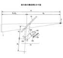
図1は実施形態に係る表示装置1が自車両8に搭載された構成の一例を示す図である。 <Configuration example>
FIG. 1 is a diagram showing an example of a configuration in which a
表示装置1は自車両8に設けられたダッシュボードの内部に埋め込まれており、表示装置1の上面に設けられた射出窓3からフロントウインドシールド71に向けて被投射画像を投射する。被投射画像はフロントウインドシールド71よりも正のY方向に虚像Iとして表示され、自車両8の運転者Vにより視認される。運転者Vは、虚像Iを視認することで、自車両8の正のY方向にある他の車両や路面等に視線を保ったまま、少ない視線移動で運転のために有用な情報を取得できる。The
なお、表示装置1はフロントウインドシールド71に被投射画像を投射できればよく、ダッシュボードの他、天井やサンバイザなどに設置されていてもよい。The
図1に示すように、表示装置1は、主要な構成要素として、投射部10と、制御部20とを備えている。投射部10は、フロントウインドシールド71に向けて被投射画像を投射する。投射部10による被投射画像の投射方式としては、レーザ走査方式及びパネル方式が知られている。レーザ走査方式は、レーザ光源から射出されたレーザビームを2次元走査デバイスで走査し中間像(後述するスクリーンに投射される実像)を形成する方式である。パネル方式は、液晶パネル、DMD(Digital Micro-mirror Device)パネル、蛍光表示管(VFD;Vacuum Fluorescent Display)等のイメージングデバイスで中間像を形成する方式である。As shown in FIG. 1, the
レーザ走査方式は、全画面を発光して部分的に遮光することで画像を形成するパネル方式とは違い、各画素に対して発光/非発光を割り当てることができるため、一般に高コントラストの画像を形成できる点で好適である。高コントラストであることで視認性が向上するため、パネル方式のHUDよりも少ない注意資源で車両の乗員が情報を視認できることが明らかになっている。Unlike the panel method, which forms an image by illuminating the entire screen and then partially blocking it, the laser scanning method can assign light emission/non-emission to each pixel, so it is generally advantageous in that it can form a high-contrast image. Since high contrast improves visibility, it has been shown that vehicle occupants can view information with fewer attention resources than with a panel-type HUD.
特に、パネル方式では情報がない領域でも遮光しきれない光が投射され、HUDが画像を表示できる範囲に表示枠が投射されてしまう(この現象をポストカードという)。レーザ走査方式ではこのような現象がなく、コンテンツのみを投影できる。特に、AR(Augmented Reality)において、実在する風景に生成した画像を重ねて表示する際のリアリティが向上する。In particular, with the panel method, light that cannot be completely blocked is projected even into areas where there is no information, resulting in a display frame being projected into the area where the HUD can display an image (this phenomenon is called a postcard). With the laser scanning method, this phenomenon does not occur, and only the content can be projected. In particular, in AR (Augmented Reality), this improves the realism when a generated image is superimposed on an existing landscape.
なお、ARとは、「拡張現実」と訳され、実在する風景に実在しないオブジェクトの画像を重ねて表示することで、目の前にある世界を仮想的に拡張する技術をいう。但し、パネル方式のHUDであってもより少ない注意資源で視認できる(疲れにくい)態様で情報を表示できるHUDであればよい。AR, translated as "augmented reality," is a technology that virtually expands the world in front of you by overlaying images of non-existent objects onto real scenery. However, even if it is a panel-type HUD, it is sufficient as long as it can display information in a way that requires less attentional resources (less fatigue).
図2は、投射部10の構成の一例を示す図である。投射部10は、主に、光源部101と、光偏向器102と、ミラー103と、スクリーン104と、凹面ミラー105とを備えている。なお、図2は主要な構成要素を示したに過ぎず、図示する以外の構成要素を備えてもよいし、図示する構成要素の一部を備えていなくてもよい。Figure 2 is a diagram showing an example of the configuration of the
光源部101は、Red(R)、Green(G)及びBlue(B)に対応した3つのレーザ光源(以下、LD:レーザダイオードとする)、カップリングレンズ、アパーチャ、合成素子及びレンズ等を備えており、3つのLDから出射されたレーザビームを合成して光偏向器102の反射面に向かって導く。光偏向器102の反射面に導かれたレーザビームは、光偏向器102により2次元的に偏向される。The
光偏向器102としては、直交する2軸に対して揺動する1つの微小なミラーや、1軸に揺動又は回動する2つの微小なミラー等を用いることができる。光偏向器102は、半導体プロセス等で作製されたMEMS(Micro Electro Mechanical Systems)ミラーとすることができる。光偏向器102は、圧電素子の変形力を駆動力とするアクチュエータにより駆動できる。但し、光偏向器102として、ガルバノミラーやポリゴンミラー等を用いてもよい。The
光偏向器102により2次元的に偏向されたレーザビームはミラー103に入射し、ミラー103により折り返され、スクリーン104の表面(被走査面)上に2次元の画像(中間像)を描画する。ミラー103としては、凹面鏡等を用いることができるが、凸面鏡や平面鏡を用いてもよい。光偏向器102とミラー103でレーザビームの方向を偏向することで、投射部10の小型化又は構成要素の配置を柔軟に変更できる。The laser beam deflected two-dimensionally by the
スクリーン104としては、レーザビームを所望の発散角で発散させる機能を有するマイクロレンズアレイやマイクロミラーアレイを用いると好適であるが、レーザビームを拡散させる拡散板、表面が平滑な透過板や反射板等を用いてもよい。一般に光源部101からスクリーン104まではHUD装置と呼ばれる。但し、この他の部品を含んでもよい。As the screen 104, it is preferable to use a microlens array or a micromirror array that has the function of diverging the laser beam at a desired divergence angle, but a diffusion plate that diffuses the laser beam, a transparent plate or a reflective plate with a smooth surface, etc. may also be used. In general, the components from the
スクリーン104から射出されたレーザビームは、凹面ミラー105で反射され、フロントウインドシールド71に投影される。凹面ミラー105はレンズと似た働きを備え、所定の焦点距離に像を結像させる機能を備える。このため、凹面ミラー105がレンズであるとすると物体に相当するスクリーン104上の像は凹面ミラー105の焦点距離によって定まる距離R2の位置に結像する。従って、自車両8の運転者V等の乗員から見た場合、フロントウインドシールド71から距離R1+R2の位置に虚像Iが表示される。自車両8の運転者Vからフロントウインドシールド71までの距離をR3とすると、図2では自車両8の運転者Vの視点Eから距離R(=R1+R2+R3)の位置に虚像Iが表示される(結像する)。 The laser beam emitted from the screen 104 is reflected by the
フロントウインドシールド71への光束の少なくとも一部は自車両8の運転者Vの視点Eに向けて反射される。この結果、自車両8の運転者Vはフロントウインドシールド71を介してスクリーン104の中間像が拡大された虚像Iを視認可能となる。換言すると、自車両8の運転者Vから見て、フロントウインドシールド71越しに中間像が拡大表示された虚像Iが表示される。At least a portion of the light beam toward the
なお、一般にフロントウインドシールド71は平面ではなく僅かに湾曲している。このため、凹面ミラー105の焦点距離だけでなくフロントウインドシールド71の曲面によっても虚像Iの結像位置が決定されるが、距離Rは上述したようにほぼ距離R1+R2によって定まる。視線移動が少なくて済むように虚像Iを遠方に結像させるには、距離R1又はR2を長くする。距離R1を長くする方法としてはミラーで光路を折り返す方法があり、距離R2を長くする方法としては凹面ミラー105の焦点距離を調整する方法がある。 Generally, the
なお、フロントウインドシールド71の影響で中間像の水平線が上又は下に凸形状となる光学歪みが生じるため、ミラー103及び凹面ミラー105の少なくとも一方は、歪みを補正するように設計、配置されることが好ましい。あるいは、投影される映像が歪みを考慮して補正されることが好ましい。In addition, because the
また、フロントウインドシールド71よりも視点E側に透過反射部材としてコンバイナを配置してもよい。コンバイナに凹面ミラー105からの光を照射するようにしても、フロントウインドシールド71に凹面ミラー105からの光を照射した場合と同様に、虚像Iとして情報を提示することができる。A combiner may also be placed as a transmissive reflective member closer to viewpoint E than the
<表示装置1が搭載される車載システム2の構成例>
次に、表示装置1が自車両8に搭載された車載システム2を、図3を参照して説明する。図3は、表示装置1が自車両8に搭載された車載システム2の構成の一例を示すブロック図である。 <Configuration Example of In-
Next, an in-
車載システム2はCAN(Controller Area Network)バス等の車載ネットワークNWを介して通信するカーナビゲーションシステム11と、エンジンECU(Electronic Control Unit)12と、表示装置1と、ブレーキECU13と、ステアリングECU14と、認識装置15と、検出装置16とを備えている。The in-
カーナビゲーションシステム11は、GPS(Global Positioning System)に代表されるGNSS(Global Navigation Satellite System)を備え、自車両8の現在地を検出して電子地図上に自車両8の位置を表示する。The
また、出発地と目的地の入力を受け付け、出発地から目的地までの経路案内情報を検索して電子地図上に表示したり、進路変更の手前で自車両8の乗員に進行方向を音声、文字(ディスプレイに表示される)、又はアニメーション等で案内したりする。なお、カーナビゲーションシステム11は携帯電話網などを介してサーバと通信してもよい。この場合、サーバが電子地図を自車両8に送信したり経路検索を行ったりすることができる。The system also accepts input of the departure point and destination, searches for route guidance information from the departure point to the destination and displays it on an electronic map, and provides guidance to the occupants of the
エンジンECU12は、各センサからの情報と自車両8の状況に合わせ、理想となる燃料噴射量の決定、点火時期の進角・遅角、動弁機構等の制御を行う。また、現在車速とアクセル開度の関係に対し変速段の切り替え線が定められたマップを参照する等して変速の必要性を判断する。エンジンECU12はこれらを組み合わせ先行車への追従走行時の加速や減速制御を行う。なお、エンジンと共に又はエンジンを動力とすることなく電気モータを動力としてもよい。The
ブレーキECU13は、ABS(Antilock Braking System)制御、先行車への追従走行時の制動制御、対象物とのTTC(Time To Collision)に基づく自動制動、坂道発進時の停止状態維持制御等、自車両8の運転者Vによるブレーキペダルの操作がなくても自車両8の車輪毎に制動力を制御する。The
ステアリングECU14は、自車両8の運転者Vによるハンドルの操舵の方向と操舵量を検出し、操舵方向に操舵トルクを付加するパワーステアリング制御を行う。また、走行レーンからの逸脱を回避する方向、走行レーンの中央の走行を維持する方向、又は障害物との接近を回避する方向に、自車両8の運転者Vによるハンドル操作がなくても操舵する。The steering
検出装置16は各種のセンサを備えており、自車両8の周囲の対象物の検出や、運転者Vによる自車両8の操作情報の検出等を行う。The
認識装置15は検出装置16が検出した対象物が何か、自車両8に対する対象物の相対位置(方向と距離)及び自車両8を示す表示部品に対する対象物の相対位置(方向と距離)を認識する。車速等の情報、及び対象物の識別結果と相対位置は表示装置1に入力される。The
<検出装置16の構成例>
次に、検出装置16の構成を、図4を参照して説明する。図4は、検出装置16の構成の一例を示すブロック図である。検出装置16は、表示装置1が表示する車速を検出する車速センサ161、表示装置1が表示する車両情報を取得する車両情報センサ162、対象物を検出するレーダセンサ163と周囲カメラ164、乗員に関する情報である乗員状態情報を取得する乗員状態情報センサ165、外部から渋滞情報などを受信するVICS受信装置166(登録商標。VICS:Vehicle Information and Communication System Center)、及びインターネットなどに接続する外部通信装置167等を備えている。 <Configuration example of
Next, the configuration of the
なお、検出装置16が備える各センサは検出装置16にまとまって存在する必要はなく、車載されていればよい。Note that the sensors provided in the
車速センサ161は、ドライブトレイン系のシャフトの回転と共に回転する磁石を、車体に固定されたセンサ部が検出し、回転速度に比例したパルス波を発生させる。単位時間のパルス数により車速を検出できる。The
車両情報センサ162は、車速センサ161以外の車両情報を検出する1つ以上のセンサを備えている。例えば、燃料計センサ、シフトレバー位置センサ、オドメータ、トリップメータ、ウィンカセンサ、及び水温センサ等である。これらは一般的な構成で各車両情報を取得できればよい。燃料計センサは現在の残燃料を検出する。The
シフトレバー位置センサは自車両8の運転者Vが操作したシフトレバー位置を検出する。オドメータは自車両8の走行距離を累積して総走行距離を提供する。トリップメータは自車両8の運転者Vが初期化してから現在までの区間走行距離を提供する。The shift lever position sensor detects the shift lever position operated by the driver V of the
ウィンカセンサは自車両8の運転者Vが操作したウィンカの方向を検出する。水温センサはエンジン冷却水の温度を検出する。これらは車両から取得できる情報の一例に過ぎず、この他、自車両8から取得できる情報は車両情報となりうる。例えば、電気自動車やハイブリッド車ではバッテリ残量、回生電力量、又は、消費電力量等も取得できる。The turn signal sensor detects the direction of the turn signal operated by the driver V of the
周囲カメラ164は車両の周囲を撮像する撮像装置である。取り付け場所は好ましくは車用の側方から後方を撮像できるように、複数の場所に設置される。例えば、自車両8のルーフやバンパにおいて車両の左後方コーナー、右後方コーナー、及び後部等に設置される。後部に設置された撮像装置をバックモニタというが、後部の周囲カメラ164はバックモニタに限られない。この他、サイドミラー、ピラー、ルーフのサイド部分、又はドアなどに配置されてもよい。なお、周囲カメラ164には前方を撮像する撮像装置が含まれてよい。例えばルームミラーの裏側やその近くに取り付けられる。The surrounding
周囲カメラ164は単眼カメラの場合とステレオカメラの場合がある。距離情報を取得できる単眼カメラ又はステレオカメラの場合、レーダセンサ163がなくてもよい。しかし、距離情報を取得できる周囲カメラ164に加え、レーダセンサ163があることで、周囲カメラ164の距離情報とレーダセンサ163の距離情報をフュージョンし(統合し)、互いのデメリットを補完しあって高精度な距離情報を取得できる。なお、レーダセンサ163と周囲カメラ164の他にソニックセンサ(超音波センサ)等を有していてもよい。The surrounding
レーダセンサ163は自車両8の前方、側方、後方など自車両8の周囲にレーダを送信し、物体で反射して戻ってくるレーダを受信する。配置場所は自車両8の周囲の障害物を検出できる場所であればよい。レーダセンサ163は送信から受信までの時間により物体までの距離を検出すると共に、レーダの照射方向により物体の方向を検出するTOF方式(Time Of Fright)がある。The
TOF方式のレーダセンサとしてLIDAR(Light Detection and Ranging、Laser Imaging Detection and Ranging)が知られている。また、連続的に送信波の周波数を大きくしながら受信波と送信波の混合波を生成し、周波数がわずかに異なることで生じる混合波のうなり周波数を距離に換算するFMCW方式(Frequency Modulation Continuous Wave)がある。FMCW方式では複数の受信アンテナで受信波の位相ずれを検出することで物体の方向を推定する。LIDAR (Light Detection and Ranging, Laser Imaging Detection and Ranging) is known as a TOF radar sensor. There is also the FMCW (Frequency Modulation Continuous Wave) method, which generates a mixed wave of the received wave and the transmitted wave while continuously increasing the frequency of the transmitted wave, and converts the beat frequency of the mixed wave, which occurs due to slight differences in frequency, into distance. With the FMCW method, the direction of an object is estimated by detecting the phase shift of the received wave with multiple receiving antennas.
乗員状態情報センサ165は自車両8の乗員から直接又は間接的に検出される乗員状態情報を検出するセンサである。代表的なものに顔カメラがある。顔カメラは自車両8の乗員の顔を撮像して顔認証を行い、自車両8の乗員を特定又は識別する。また、顔画像から顔の向きや視線方向を検出することが可能になる。The occupant
この他、乗員状態情報センサ165は、例えば、心電センサ、心拍数センサ、血圧センサ、体温センサ、脈拍センサ、呼吸センサ、発汗センサ、瞬きセンサ、瞳孔センサ、脳波センサ、又は、筋電位センサ等でもよい。乗員状態情報センサ165としては例えば、腕時計型のウェアラブル端末(スマートウォッチ)を車両の乗員が装着する形態がある。In addition, the occupant
VICS受信装置166はVICSが配信する電波を受信する。なお、VICSは渋滞や交通規制等の道路交通情報を、FM多重放送やビーコンを使ってリアルタイムに車載装置に送信するシステムである。外部通信装置167は3G、4G、5G、LTE及び無線LAN等のネットワークを介してインターネット等に接続し各種の情報を受信する。例えば、雨、雪、霧などの天候情報を受信できる。The
また、ニュース、音楽、動画等を受信してもよい。また、外部通信装置167は、例えば信号機の状態情報と信号が変わるまでの時間等を取得できる。このように、VICS受信装置166と外部通信装置167は路車間通信を行う場合がある。この他、外部通信装置167は車間通信で他車両6が検出した情報を取得してもよい。It may also receive news, music, videos, etc. The
なお、先進運転システム(ADAS)では情報を表示して警告するだけでなく、自車両8の制御を行う場合もある。この場合、ECUはレーダセンサ163又は周囲カメラ164の少なくとも一方が検出する対象物の距離情報に基づいてエンジンECU12、ブレーキECU13及びステアリングECU14と連携して各種の運転支援を行う。例えば、先行車への追従走行時の加減速制御、自動制動、走行レーンからの逸脱回避、レーンキープ走行、及び、対象物の回避操舵等を行う。このような制御のために、周囲カメラ164が撮像した画像から、ECUが白線等の道路ペイント等を認識する。Note that the advanced driving system (ADAS) may not only display information and warn, but may also control the
追従走行時の加減速制御では、ECUは車速に応じた目標の距離を維持するように動力と制動力を制御する。自動制動では、TTCに応じて、警告、ブレーキペダルの押下を促す表示及び衝突の可能性が高い場合におけるシートベルトの巻き上げと衝突回避制動等を行う。走行レーンからの逸脱回避では、運転支援ECU36は撮像された画像から白線(走行区分線)を認識し、走行レーンを逸脱する方向と反対方向に操舵トルクを付加する。In acceleration and deceleration control during following, the ECU controls power and braking to maintain a target distance according to the vehicle speed. In automatic braking, depending on the TTC, it issues a warning, displays a message encouraging the driver to press the brake pedal, and, if there is a high possibility of a collision, it retracts the seat belt and applies collision avoidance braking. In avoiding deviation from the driving lane, the driving assistance ECU 36 recognizes white lines (traffic lane markings) from the captured image and applies steering torque in the opposite direction to the direction of deviation from the driving lane.
また、レーンキープ走行では走行レーンの中央を目標走行ラインに設定し、目標走行ラインからの乖離に比例した操舵トルクを乖離とは反対方向に付加する。対象物の回避操舵では、制動では衝突を回避できないと判断した場合に、対象物を回避するための走行ラインを決定し、この走行ラインを走行する操舵トルクを付加する。In lane keeping driving, the center of the driving lane is set as the target driving line, and a steering torque proportional to the deviation from the target driving line is applied in the opposite direction to the deviation. In object avoidance steering, if it is determined that a collision cannot be avoided by braking, a driving line to avoid the object is determined, and a steering torque is applied to drive along this driving line.
また、例えば車線変更時にレーダセンサ163又は周囲カメラ164により、隣の車線のドアミラーに映らない領域(死角領域)を併走する車両を検知した場合に、乗員に警告する。このような支援をブラインドスポットモニタという。For example, when changing lanes, if the
<認識装置15の機能構成例>
次に、認識装置15の機能構成について図5を参照して説明する。図5は認識装置15が備える機能構成の一例を示すブロック図である。認識装置15は対象判断部151と相対位置決定部152を備える。 <Example of functional configuration of
Next, the functional configuration of the
対象判断部151は主に周囲カメラ164が撮像して得た周囲画像データを解析して写っている対象物の分類を判断する。実施形態では、例えば、他車両、歩行者、二輪車、又はその他等を判断する。The
なお、周囲カメラ164がステレオカメラの場合、周囲画像データの各画素又は画素ブロックには距離情報が含まれている。このような周囲画像データを距離画像という。また、対象判断部151は周囲画像データだけでなく、レーダ測距情報からも対象物を判断できる。例えば、LIDARの点群の密度が十分に高い場合、対象物の形状が得られるので、形状を解析して対象物の分類を判断できる。When the surrounding
対象判断部151が対象を判断する方法の1つとして、機械学習を用いた画像認識方法がある。機械学習とは、コンピュータに人のような学習能力を獲得させるための技術であり,コンピュータが,データ識別等の判断に必要なアルゴリズムを,事前に取り込まれる学習データから自律的に生成し,新たなデータについてこれを適用して予測を行う技術のことをいう。機械学習のための学習方法は、教師あり学習、教師なし学習、半教師学習、強化学習、深層学習のいずれかの方法でもよく、更に、これらの学習方法を組み合わせた学習方法でもよく、機械学習のための学習方法は問わない。なお、機械学習の手法には、パーセプトロン、ディープラーニング、サポートベクターマシン、ロジスティック回帰、ナイーブベイズ、決定木、ランダムフォレストなどがある。One method by which the
相対位置決定部152は、図6に示すように、自車両8又は自車両8を示す表示部品62に対する対象物の相対位置(方向と距離)を決定する。図6は、自車両8又は自車両8を示す表示部品62に対する対象物の相対位置の一例を説明する図である。図6に示すように、自車両8を示す表示部品62(虚像Iの中心)が、自車両8の中心から車幅方向にQ、車長方向にPの位置に表示されるものとする。The relative
周囲画像データ又はレーダ測距情報により他車両6が自車両8の中心を原点に(A,B)の座標であることが検出されたものとする。また、自車両8の中心から他車両6までの距離をL1、その方向をθ1で表す。なお、周囲画像データが距離画像の場合、(A,B)を直接求められるが、レーダ測距情報の場合は距離と方向を(A,B)に分解すればよい。相対位置決定部152は座標(A,B)を、自車両8を示す表示部品62を基準とする座標(C,D)に変換する。 It is assumed that the coordinates of the
自車両8を示す表示部品62は虚像Iとして提示されるので自車両8の前方の決まった位置に存在する。上記のように車両の中心から自車両8を示す表示部品62までの車幅方向の距離をQ、車長方向の距離をPとすると座標(C,D)は以下のように決定される。
(C、D)=(A+Q,B+P) The
(C, D)=(A+Q,B+P)
相対位置決定部152は車両に配置された各レーダセンサ又は周囲カメラ毎に同様の処理を行い、自車両8を示す表示部品62に対する対象物の相対位置を決定する。相対位置を決定することで距離と方向も求められる。自車両8を示す表示部品62から他車両6までの距離をL2、その方向をθ2で表す。図6の例では、距離L2=√(C2+D2)、方向θ2=arctan(D/C)である。なお、方向θ1、θ2の基準(どの方向を0度とするか)は適宜設定されてよい。図6では9時の方向を0度としている。 The relative
認識装置15は、対象判断部151が判断した対象物の分類を示す分類情報と、相対位置決定部152が取得した自車両8から対象物までの距離情報と、自車両8に対する対象物の相対位置を示す位置情報とを制御部20に出力する。The
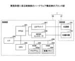
<制御部20のハードウェア構成例>
次に、制御部20のハードウェア構成を、図7を参照して説明する。図7は、制御部20のハードウェア構成の一例を示すブロック図である。図7に示すように、制御部20は、FPGA(Field-Programmable Gate Array)201と、CPU(Central Processing Unit)202と、ROM(Read Only Memory)203と、RAM(Random Access Memory)204と、I/F(Interface)205と、バスライン206と、LDドライバ207と、MEMSコントローラ208とを備えている。FPGA201、CPU202、ROM203、RAM204、及びI/F205は、バスライン206を介して相互に接続されている。 <Example of Hardware Configuration of
Next, the hardware configuration of the
CPU202は、制御部20の各機能を制御する。ROM203は、CPU202が、制御部20の各機能を制御するために実行するプログラム203pを記憶している。RAM204にはプログラム203pが展開され、CPU202がプログラム203pを実行するためのワークエリアとして使用される。また、RAM204は画像メモリ209を備えている。The
画像メモリ209は虚像Iとして投影される画像の生成に使用される。I/F205は、認識装置15や検出装置16と通信するためのインターフェイスであり、車両9のCAN(Controller Area Network)バス又はイーサネット(登録商標)等に接続される。The
FPGA201は、CPU202が作成した画像に基づいてLDドライバ207を制御する。LDドライバ207は投射部10の光源部101のLDを駆動することで、画像に応じたLDの発光を制御する。FPGA201は、画像の画素位置に応じた方向にレーザビームが偏向されるようにMEMSコントローラ208を介して投射部10の光偏向器102を動作させる。The
<制御部20の機能構成例>
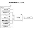
次に、制御部20の機能構成について、図8を参照して説明する。図8は、制御部20の機能構成の一例を示すブロック図である。 <Example of functional configuration of
Next, the functional configuration of the
図8に示すように、制御部20は、残距離取得部21と、判定部22と、方向決定部23と、画像生成部24と、出力部25とを備えている。これらのうち、残距離取得部21、判定部22、方向決定部23及び画像生成部24の機能は、図7のCPU202が所定のプログラムを実行すること等により実現される。また出力部25の機能は図7のI/F205等により実現される。As shown in FIG. 8, the
残距離取得部21は、カーナビゲーションシステム11から入力した経路案内情報に基づいて、提示画像を提示する地点に自車両8が到達するまでの残距離情報を取得し、取得結果を判定部22に出力する。The remaining
判定部22は、残距離が所定の提示閾値以下になったか否かを判定し、判定結果を方向決定部23に出力する。The
方向決定部23は、残距離が提示閾値以下になった場合に、カーナビゲーションシステム11から入力した経路案内情報に基づき、自車両8の走行予定経路における走行予定方向を決定し、決定結果を画像生成部24に出力する。例えば、自車両8の走行予定経路に交差点がある場合には、交差点で自車両8が進むべき方向を決定する。When the remaining distance becomes equal to or less than the presentation threshold, the
画像生成部24は、方向決定部23が決定した走行予定方向に応じて、自車両8の走行予定経路における走行予定方向を提示するための提示画像を生成する。そして、生成した提示画像の画像データを、出力部25を介して投射部10に出力する。The
投射部10(図1参照)は、入力した提示画像データに基づき、フロントウインドシールド71に提示画像を含む被投射画像を投射し、提示画像の虚像を自車両8の運転者Vに視認させる。The projection unit 10 (see FIG. 1) projects a projected image including a presentation image onto the
なお、画像生成部24は、提示画像だけでなく、残距離取得部21が取得した残距離情報を表示する残距離画像や、図4の車速センサ161が検出した自車両8の車速情報を表示する車速画像等の他の画像を生成することもできる。そして、提示画像や残距離画像、車速画像等が1つの画像内に配置された被投射画像データを、出力部25を介して投射部10に出力できる。The
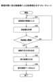
<制御部20による処理例>
次に、制御部20による処理の流れを、図9を参照して説明する。図9は、制御部20による処理の一例を示すフローチャートである。 <Example of processing by
Next, the flow of processing by the
まず、ステップS91において、残距離取得部21及び方向決定部23は、カーナビゲーションシステム11から経路案内情報を入力する。First, in step S91, the remaining
続いて、ステップS92において、残距離取得部21は、経路案内情報に基づいて、自車両8が提示画像を提示する地点に到達するまでの残距離情報を取得し、取得結果を判定部22に出力する。Next, in step S92, the remaining
続いて、ステップS93において、判定部22は、残距離が提示閾値以下になったか否かを判定する。Next, in step S93, the
ステップS93で残距離が提示閾値以下でないと判定された場合には(ステップS93、No)、ステップS91以降の処理が再度繰り返される。If it is determined in step S93 that the remaining distance is not equal to or less than the presentation threshold (step S93, No), the processing from step S91 onwards is repeated again.
一方、ステップS93で残距離が提示閾値以下であると判定された場合には(ステップS93、Yes)、ステップS94において、方向決定部23は、経路案内情報に基づき、自車両8の走行予定方向を決定する。On the other hand, if it is determined in step S93 that the remaining distance is equal to or less than the presentation threshold (step S93, Yes), in step S94, the
続いて、ステップS95において、画像生成部24は、方向決定部23が決定した走行予定方向に応じて提示画像を生成する。Next, in step S95, the
続いて、ステップS96において、出力部25は提示画像データを投射部10に出力する。Next, in step S96, the
このようにして、制御部20は提示画像を生成し、投射部10に出力できる。なお、ステップS91~S94までの間に、画像生成部24は、上述した残距離画像や車速画像等を生成し、これらを含む被投射画像データを、出力部25を介して投射部10に出力することもできる。この場合は、提示画像が含まれずに残距離画像や車速画像等が含まれる被投射画像が自車両8の前景に重畳表示される。In this way, the
(各種表示例)
次に、表示装置1による各種表示例について説明する。以下では、図3のカーナビゲーションシステム11を用いて目的地が設定された状態で、自車両8の前景に画像が重畳表示された場合を一例として説明する。また一般的なカーナビゲーションシステムでは、交差点や道路が分岐する分岐点毎で、車両の走行予定経路を案内する。そのため、これに対応して交差点や分岐点毎で提示画像を表示して、走行予定経路を案内する場合を一例として説明する。 (Various display examples)
Next, various display examples by the
まず、図10は、残距離が提示閾値以下でない場合における自車両8の前景300への表示の一例を示す図である。First, FIG. 10 shows an example of a display on the
前景300には、先行車両301や道路302等が含まれている。また、前景300には、車速画像303と、残距離画像304とが重畳表示されている。The
車速画像303は、自車両8の現在の車速を表示する画像である。図10の例では、車速として70(km/h)が表示されている。The
残距離画像304は、提示画像を提示する地点に自車両8が到達するまでの残距離を表示する画像である。図10の例では、提示画像を提示する地点として「都筑I.C.」が表示されるとともに、「都筑I.C.」までの残距離である200mmが表示されている。The remaining
残距離画像304は、残距離が所定の表示閾値(例えば500m)以下になった場合に表示され、残距離が提示閾値(例えば100m)以下になるまで表示される。図10では残距離が提示閾値以下ではないため、提示画像がまだ表示されていない。The remaining
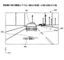
次に、図11は、残距離が提示閾値以下である場合における自車両8の前景300aへの表示の一例を示す図である。Next, FIG. 11 shows an example of a display in the
前景300aには、道路302に交差する交差道路305が現れている。また、残距離が提示閾値以下になったため、前景300aでは、図10における残距離画像304が非表示となり、提示画像306が新たに表示されている。In the
提示画像306は、交差道路305に案内(誘導)するように、自車両8の走行予定方向を提示する画像である。図11に示すように、提示画像306は、2つの矢印図形306a及び306bを含んで構成されている。The
矢印図形306a及び306bは、交差道路305を指示するように方向性を備えている。矢印図形306a及び306bが指示する方向が自車両8の走行予定方向(移動体の移動予定方向)に対応する。The arrow shapes 306a and 306b have a directionality that indicates the intersecting
また矢印図形306a及び306bのそれぞれは、Z方向における投射部10の投射画角に対応するサイズより小さい画像サイズの図形であり、正のZ方向から負のZ方向に向けて断続的に表示されている。Each of the arrow figures 306a and 306b is a figure with an image size smaller than the size corresponding to the projection angle of the
ここで、図11に矢印で示したZ方向は、前景300a内の垂直方向に沿う方向に対応し、X方向は前景300a内の水平方向に沿う方向に対応する。この点は、以降の図12~15に示すX方向及びZ方向においても同様である。なお、被投射画像のサイズと投射画角との関係は、図13を用いて後述する。The Z direction indicated by the arrow in FIG. 11 corresponds to the vertical direction in the
自車両8の運転者Vは、前景300aに重畳表示された提示画像306を視認することで、走行予定経路における走行予定方向を分かりやすく認識できる。The driver V of the
この矢印図形306a及び306bは「複数の図形」の一例である。なお、図11の例では、2個の矢印を示したが、これに限定されるものではなく、矢印の個数はさらに増加させてもよい。また、図形は矢印に限定されるものではなく、方向を指示するものであれば任意の形状の図形であってもよい。These arrow shapes 306a and 306b are an example of "multiple shapes." Note that, although two arrows are shown in the example of FIG. 11, this is not limiting and the number of arrows may be increased. Also, the shapes are not limited to arrows and may be shapes of any shape as long as they indicate a direction.
また、図11において、破線で示した領域307は、被投射画像が表示される領域を示している。前景300aにおける領域307の領域内に被投射画像が表示されている。提示画像306は被投射画像に含まれる画像であるため、この領域307内に表示される。なお、領域307は被投射画像が表示される領域を説明するために図示したものであり、自車両8の前景300aに表示されるものではない。In addition, in FIG. 11,
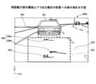
次に、図12は、被投射画像のサイズと提示画像との関係を説明する図である。(a)は比較例に係る被投射画像のサイズと提示画像との関係を示す図、(b)は実施形態に係る被投射画像のサイズと提示画像との関係を示す図である。また、図12は、図10及び図11における前景への被投射画像の重畳表示を、自車両8の上方(上空から見下ろす方向)から見た図に対応する。Next, FIG. 12 is a diagram explaining the relationship between the size of the projected image and the presented image. (a) is a diagram showing the relationship between the size of the projected image and the presented image in a comparative example, and (b) is a diagram showing the relationship between the size of the projected image and the presented image in the embodiment. Also, FIG. 12 corresponds to a view of the superimposed display of the projected image on the foreground in FIGS. 10 and 11 as viewed from above the vehicle 8 (looking down from the sky).
図12(a)では、道路302を走行する自車両8の走行予定経路を提示するために、経路に沿って伸びる太矢印の提示画像306'が表示されている。この場合、走行予定経路に沿って太矢印を伸ばす必要があるため、提示画像306'を含む被投射画像には、重畳範囲308'を提示可能なサイズが要求される。ここで重畳範囲とは、投射部10の投射画角と俯角(見下ろし角)により決定される範囲であり、前景と被投射画像とが重畳する範囲をいう。In FIG. 12(a), a presentation image 306' of a thick arrow extending along the route is displayed to present the planned driving route of the
これに対し、図12(b)に示すように、実施形態に係る提示画像306は、走行予定方向を提示するため、経路全体を示すように提示画像306を提示しなくてもよい。そのため、図12(a)における重畳範囲308'と比較して小さい重畳範囲308を提示可能なサイズで被投射画像を生成可能になっている。In contrast, as shown in FIG. 12(b), the
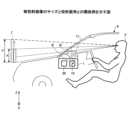
次に、図13は、被投射画像のサイズと投射部10による投射画角との関係の一例を説明する図である。図13において、虚像I'は比較例に係る虚像を示している。虚像I'は、投射画角φ'で被投射画像が投射されることで、運転者Vに視認される被投射画像の虚像である。一方、虚像Iは実施形態に係る虚像を示している。虚像Iは投射画角φで被投射画像が投射されることで、運転者Vに視認される被投射画像の虚像である。Next, FIG. 13 is a diagram illustrating an example of the relationship between the size of the projected image and the projection angle of the
実施形態に係る提示画像306を含む被投射画像の虚像IのZ方向におけるサイズhは、比較例に係る提示画像306'を含む被投射画像の虚像I'のZ方向におけるサイズh'と比較して小さい。そのため、投射画角φ'と比較して狭い投射画角φで提示画像306を提示し、経路案内情報を提示することが可能になっている。The size h in the Z direction of the virtual image I of the projected image including the presented
ここで、投射画角φは、垂直方向に沿うZ方向における投射部10の最大投射画角に対応する。Here, the projection angle of view φ corresponds to the maximum projection angle of the
次に、図14は、提示画像306における矢印図形306a及び306bの表示間隔と、重畳範囲との関係の一例を説明する図である。図14において、表示間隔dは矢印図形306a及び306bの表示間隔を示し、重畳距離eは自車両8の走行方向(X方向及びY方向の両方に直交する方向)における重畳範囲の長さ(距離)を示している。図14に示すように、表示間隔dは重畳距離eより小さいことが好ましい。また表示間隔dを、Z方向における投射部10の最大投射画角以下にすると、矢印図形306a及び306b等の複数の図形を前景に表示でき、複数の図形で走行予定方向をより分かりやすく提示できるため、好適である。Next, FIG. 14 is a diagram illustrating an example of the relationship between the display interval of the arrow figures 306a and 306b in the presented
<表示装置1による作用効果>
以上説明したように、実施形態では、経路案内情報として自車両8の走行予定方向を提示する提示画像を生成し、自車両8に備えられた投射部10で提示画像を含む被投射画像を投射して表示する。自車両8の走行予定経路を提示するための大きな画像を投射せず、自車両8の移動予定方向を提示する小さな画像を投射するため、狭い投射画角φ(図13参照)で提示画像306を提示して経路案内情報を提示できる。これにより、表示装置1のサイズやコストが増大することを回避できる。 <Functions and Effects of
As described above, in the embodiment, a presentation image presenting the planned driving direction of the
また、実施形態に係る提示画像306は、投射部10の投射画角に対応するサイズより小さい画像サイズの複数の図形である矢印図形306a及び306bを含んで構成されている。また、矢印図形306a及び306bは、正のZ方向から負のZ方向に向けて断続的に表示されている。このようにすることで、走行予定経路に沿って伸びる太矢印の提示画像を前景の道路に重畳させる場合と比較して、前景の道路に重畳される提示画像306の面積を小さくすることができる。これにより、前景における視覚的な煩わしさ(煩雑さ)を解消できる。In addition, the presented
ここで、提示画像306における矢印図形306a及び306bの表示位置によっても、走行予定方向を提示できる。図15は提示画像306における矢印図形306a及び306bの表示位置の一例を説明する図である。Here, the planned driving direction can also be presented based on the display positions of the arrow figures 306a and 306b in the
矢印図形306a及び306bを、運転者Vの中心軸309上に表示すると最も簡易的であるが、交差点の基準位置310を定め、基準位置310と運転者Vとを結ぶ直線状に矢印図形306a及び306bが配置されるように表示してもよい。It is simplest to display the arrow figures 306a and 306b on the
このような表示状態を自車両8の前景300aを視認した場合に置き換えて説明する。提示画像306の虚像は、前景300a内の垂直方向に沿う方向に配列された複数の図形で、走行予定方向を提示する。この複数の図形は、前景内の垂直方向に沿う方向における交差点に近い位置で走行予定方向を提示する図形ほど、前景内の水平方向に沿う方向における交差点に近い位置で走行予定方向を提示する。This display state will be explained by replacing it with a case where the
図11を参照してより具体的に述べると、提示画像306を構成する矢印図形306a及び306bのうち、前景300a内の垂直方向に沿う方向(Z方向)における交差道路305に近い位置で走行予定方向を提示する矢印図形306aは、矢印図形306bと比較して、前景300a内の水平方向に沿う方向(X方向)における交差道路305に近い位置で走行予定方向を提示する。More specifically, referring to FIG. 11, of the arrow figures 306a and 306b constituting the
このようにすることで、矢印図形306a及び306bの向きだけでなく、矢印図形306a及び306bの表示位置によっても、運転者Vは走行予定方向を認識可能になる。By doing this, the driver V can recognize the intended driving direction not only from the direction of the arrow figures 306a and 306b but also from the display position of the arrow figures 306a and 306b.
なお、上述した実施形態における残距離画像304は、提示画像を提示する地点の情報と、この地点に自車両8が到達するまでの残距離の情報を提示するため、経路案内情報を提示する提示画像ということもできる。但し、残距離画像304は文字情報であり、表示のために広い投射画角を必要とするものではないため、投射画角への影響は小さい。Note that the remaining
<その他の好適例>
以上、本発明を実施するための最良の形態について実施例を用いて説明したが、本発明はこうした実施例に限定されるものではなく、本発明の要旨を逸脱しない範囲内において種々の変形及び置換を加えることができる。 <Other preferred examples>
The above describes the best mode for carrying out the present invention using examples, but the present invention is not limited to these examples, and various modifications and substitutions can be made within the scope that does not deviate from the gist of the present invention.
なお、上述した実施形態において、認識装置15の備える機能の一部、又は全部を制御部20が備える構成にしてもよい。また、制御部20の備える機能の一部を認識装置15やカーナビゲーションシステム11、検出装置16等の他の構成要素が備える構成にしてもよい。In the above-described embodiment, some or all of the functions of the
また、実施形態は表示方法も含む。例えば、表示方法は、被投射画像を表示する表示装置による表示方法であって、経路案内情報を提示する提示画像を生成する工程と、移動体に備えられた投射部により前記提示画像を含む前記被投射画像を投射する工程と、を行い、前記提示画像は、前記移動体の移動予定方向を提示する。このような表示方法により、上述した表示装置と同様の効果を得ることができる。The embodiment also includes a display method. For example, the display method is a display method using a display device that displays a projected image, and includes a step of generating a presentation image that presents route guidance information, and a step of projecting the projected image including the presentation image by a projection unit provided on a moving object, and the presentation image presents the planned direction of movement of the moving object. Such a display method can provide the same effect as the display device described above.
また、実施形態はプログラムも含む。例えば、プログラムは、被投射画像を表示する表示装置で動作するプログラムであって、経路案内情報を提示する提示画像を生成し、移動体に備えられた投射部により前記提示画像を含む前記被投射画像を投射する処理をコンピュータに実行させ、前記提示画像は、前記移動体の移動予定方向を提示する。このようなプログラムにより、上述した表示装置と同様の効果を得ることができる。The embodiment also includes a program. For example, the program is a program that runs on a display device that displays a projected image, and causes a computer to execute a process of generating a presentation image that presents route guidance information, and projecting the projected image including the presentation image by a projection unit provided on a moving object, and the presentation image presents the planned direction of movement of the moving object. Such a program can provide the same effect as the display device described above.
上記で説明した実施形態の各機能は、一又は複数の処理回路によって実現することが可能である。ここで、本明細書における「処理回路」とは、電子回路により実装されるプロセッサのようにソフトウェアによって各機能を実行するようプログラミングされたプロセッサや、上記で説明した各機能を実行するよう設計されたASIC(Application Specific Integrated Circuit)、DSP(digital signal processor)、FPGA(field programmable gate array)や従来の回路モジュール等のデバイスを含むものとする。Each function of the above-described embodiments can be realized by one or more processing circuits. In this specification, the term "processing circuit" includes a processor programmed to execute each function by software, such as a processor implemented by an electronic circuit, and devices such as an ASIC (Application Specific Integrated Circuit), DSP (digital signal processor), FPGA (field programmable gate array), and conventional circuit modules designed to execute each function described above.
1 表示装置
2 車載システム
8 自車両(移動体の一例)
10 投射部
11 カーナビゲーションシステム
15 認識装置
16 検出装置
164 周囲カメラ
20 制御部
21 残距離取得部
22 判定部
23 方向決定部
24 画像生成部
25 出力部
300、300a 前景
301 先行車両
302 道路
303 車速画像
304 残距離画像
305 交差道路
306 提示画像
306a、306b 矢印図形(複数の図形の一例)
307 領域
308 重畳範囲
d 表示間隔
e 重畳距離
h Z方向における虚像のサイズ
I 虚像
V 運転者
X 前景における水平方向に沿う方向
Z 前景における垂直方向に沿う方向
φ 投射画角1
10
307
Claims (6)
Translated fromJapanese経路案内情報を提示する提示画像を生成する画像生成部と、
移動体に備えられ、前記提示画像を含む前記被投射画像を投射する投射部と、を備え、
前記提示画像は、前記移動体の移動予定方向を提示し、
前記提示画像の虚像を前記移動体の前景に重畳表示し、
前記提示画像の虚像は、前記前景内の垂直方向に沿う方向に配列された複数の図形で前記前景内の交差点における前記移動予定方向を提示し、
前記複数の図形のそれぞれの間隔は、前記垂直方向に沿う方向における前記投射部の最大投射画角以下であり、
前記複数の図形の表示間隔は、前記移動体の走行方向における重畳範囲の長さを示す重畳距離よりも小さい
表示装置。 A display device that displays a projected image,
an image generating unit that generates a presentation image that presents route guidance information;
a projection unit that is provided on a moving object and projects the projected image including the presentation image;
the presentation image presents a planned movement direction of the moving object,
A virtual image of the presented image is superimposed on the foreground of the moving object,
the virtual image of the presentation image presents the intended travel direction at the intersection in the foreground with a plurality of figures arranged in a vertical direction in the foreground,
an interval between each of the plurality of figures is equal to or smaller than a maximum projection angle of the projection unit in a direction along the vertical direction;
The display interval of the plurality of figures is smaller than an overlap distance indicating the length of the overlap range in the running direction of the moving object.
Display device.
請求項1に記載の表示装置。 The display device according to claim1 , wherein the graphic is an image of an arrow graphic having a direction indicating the intended direction of movement.
請求項1、又は2に記載の表示装置。The display device ofclaim 1 or 2, wherein the plurality of figures present the intended direction of travel at a position closer to the intersection in a direction along the vertical direction inthe foreground, and the figure presents the intended direction of travel at a position closer to the intersection inadirection along the horizontal direction in the foreground.
経路案内情報を提示する提示画像を生成する工程と、
移動体に備えられた投射部により前記提示画像を含む前記被投射画像を投射する工程と、を行い、
前記提示画像は、前記移動体の移動予定方向を提示し、
前記提示画像の虚像を前記移動体の前景に重畳表示し、
前記提示画像の虚像は、前記前景内の垂直方向に沿う方向に配列された複数の図形で前記移動予定方向を提示し、
前記複数の図形のそれぞれの間隔は、前記垂直方向に沿う方向における前記投射部の最大投射画角以下であり、
前記複数の図形の表示間隔は、前記移動体の走行方向における重畳範囲の長さを示す重畳距離よりも小さい
表示方法。 A display method for displaying a projected image by a display device,the display device comprising:
generating a presentation image presenting route guidance information;
projecting the projected image including the presented image by a projection unit provided on a moving object;
the presentation image presents a planned movement direction of the moving object,
A virtual image of the presented image is superimposed on the foreground of the moving object,
the virtual image of the presentation image presents the intended movement direction with a plurality of figures arranged in a vertical direction in the foreground;
an interval between each of the plurality of figures is equal to or smaller than a maximum projection angle of the projection unit in a direction along the vertical direction;
The display interval of the plurality of figures is smaller than an overlap distance indicating the length of the overlap range in the running direction of the moving object.
Display method.
経路案内情報を提示する提示画像を生成し、
移動体に備えられた投射部により前記提示画像を含む前記被投射画像を投射する
処理をコンピュータに実行させ、
前記提示画像は、前記移動体の移動予定方向を提示し、
前記提示画像の虚像を前記移動体の前景に重畳表示し、
前記提示画像の虚像は、前記前景内の垂直方向に沿う方向に配列された複数の図形で前記移動予定方向を提示し、
前記複数の図形のそれぞれの間隔は、前記垂直方向に沿う方向における前記投射部の最大投射画角以下であり、
前記複数の図形の表示間隔は、前記移動体の走行方向における重畳範囲の長さを示す重畳距離よりも小さい
プログラム。 A program that operates on a display device that displays a projected image,
generating a presentation image presenting route guidance information;
causing a computer to execute a process of projecting the projected image including the presented image by a projection unit provided on a moving object;
the presentation image presents a planned movement direction of the moving object,
A virtual image of the presented image is superimposed on the foreground of the moving object,
the virtual image of the presentation image presents the intended movement direction with a plurality of figures arranged in a vertical direction in the foreground;
an interval between each of the plurality of figures is equal to or smaller than a maximum projection angle of the projection unit in a direction along the vertical direction;
The display interval of the plurality of figures is smaller than an overlap distance indicating the length of the overlap range in the running direction of the moving object.
program.
Priority Applications (2)
| Application Number | Priority Date | Filing Date | Title |
|---|---|---|---|
| EP21704029.4AEP4093629A1 (en) | 2020-01-24 | 2021-01-20 | Display apparatus, movable body, display method, program, and non-transitory recording medium |
| PCT/JP2021/001913WO2021149740A1 (en) | 2020-01-24 | 2021-01-20 | Display apparatus, movable body, display method, program, and non-transitory recording medium |
Applications Claiming Priority (2)
| Application Number | Priority Date | Filing Date | Title |
|---|---|---|---|
| JP2020010358 | 2020-01-24 | ||
| JP2020010358 | 2020-01-24 |
Publications (2)
| Publication Number | Publication Date |
|---|---|
| JP2021117220A JP2021117220A (en) | 2021-08-10 |
| JP7585754B2true JP7585754B2 (en) | 2024-11-19 |
Family
ID=77174650
Family Applications (1)
| Application Number | Title | Priority Date | Filing Date |
|---|---|---|---|
| JP2020205061AActiveJP7585754B2 (en) | 2020-01-24 | 2020-12-10 | Display device, mobile object, display method, and program |
Country Status (1)
| Country | Link |
|---|---|
| JP (1) | JP7585754B2 (en) |
Citations (5)
| Publication number | Priority date | Publication date | Assignee | Title |
|---|---|---|---|---|
| JP2017021019A (en) | 2015-07-08 | 2017-01-26 | 日産自動車株式会社 | Vehicular display apparatus and vehicular display method |
| WO2017056211A1 (en) | 2015-09-30 | 2017-04-06 | 日産自動車株式会社 | Vehicular display device |
| WO2017134865A1 (en) | 2016-02-05 | 2017-08-10 | 日立マクセル株式会社 | Head-up display device |
| JP2019119318A (en) | 2017-12-28 | 2019-07-22 | アルパイン株式会社 | On-vehicle system |
| JP2019174456A (en) | 2018-03-29 | 2019-10-10 | 株式会社リコー | Image control device, display device, vehicle, image control method, and program |
- 2020
- 2020-12-10JPJP2020205061Apatent/JP7585754B2/enactiveActive
Patent Citations (5)
| Publication number | Priority date | Publication date | Assignee | Title |
|---|---|---|---|---|
| JP2017021019A (en) | 2015-07-08 | 2017-01-26 | 日産自動車株式会社 | Vehicular display apparatus and vehicular display method |
| WO2017056211A1 (en) | 2015-09-30 | 2017-04-06 | 日産自動車株式会社 | Vehicular display device |
| WO2017134865A1 (en) | 2016-02-05 | 2017-08-10 | 日立マクセル株式会社 | Head-up display device |
| JP2019119318A (en) | 2017-12-28 | 2019-07-22 | アルパイン株式会社 | On-vehicle system |
| JP2019174456A (en) | 2018-03-29 | 2019-10-10 | 株式会社リコー | Image control device, display device, vehicle, image control method, and program |
Also Published As
| Publication number | Publication date |
|---|---|
| JP2021117220A (en) | 2021-08-10 |
Similar Documents
| Publication | Publication Date | Title |
|---|---|---|
| JP7222285B2 (en) | DISPLAY CONTROL DEVICE, DISPLAY DEVICE, DISPLAY SYSTEM, MOBILE OBJECT, PROGRAM, IMAGE GENERATION METHOD | |
| JP7254832B2 (en) | HEAD-UP DISPLAY, VEHICLE DISPLAY SYSTEM, AND VEHICLE DISPLAY METHOD | |
| JP7074432B2 (en) | Vehicle control systems, vehicle control methods, and vehicle control programs | |
| JP6699675B2 (en) | Information provision device | |
| US20210016793A1 (en) | Control apparatus, display apparatus, movable body, and image display method | |
| CN109032124A (en) | Vehicle control system, control method for vehicle and storage medium | |
| CN108973857A (en) | Vehicle control system, control method for vehicle and storage medium | |
| CN110834583A (en) | Display system for vehicle and vehicle | |
| WO2020208989A1 (en) | Display control device and display control program | |
| JP2021117704A (en) | Display device and display method | |
| US11412205B2 (en) | Vehicle display device | |
| WO2019189515A1 (en) | Control apparatus, display apparatus, movable body, and image display method | |
| JP2019172243A (en) | Control device, display device, movable body, control method and program | |
| JP7577988B2 (en) | Display device, mobile object, display method, and program | |
| JP7111121B2 (en) | Display control device and display control program | |
| WO2021132259A1 (en) | Display apparatus, display method, and program | |
| JP7400242B2 (en) | Vehicle display control device and vehicle display control method | |
| JP7585754B2 (en) | Display device, mobile object, display method, and program | |
| JP2021117089A (en) | Display device and display method | |
| WO2021149740A1 (en) | Display apparatus, movable body, display method, program, and non-transitory recording medium | |
| EP4081421B1 (en) | Display apparatus, moving body, display method, and program | |
| JP7037764B2 (en) | Travel route guidance device, mobile body, travel route guidance method and program | |
| JP2021104803A (en) | Display device, display method and program | |
| JP2021109555A (en) | Display control device, system, display system, information display method | |
| WO2021132250A1 (en) | In-vehicle display device and program |
Legal Events
| Date | Code | Title | Description |
|---|---|---|---|
| A621 | Written request for application examination | Free format text:JAPANESE INTERMEDIATE CODE: A621 Effective date:20231011 | |
| A131 | Notification of reasons for refusal | Free format text:JAPANESE INTERMEDIATE CODE: A131 Effective date:20240702 | |
| A521 | Request for written amendment filed | Free format text:JAPANESE INTERMEDIATE CODE: A523 Effective date:20240830 | |
| TRDD | Decision of grant or rejection written | ||
| A01 | Written decision to grant a patent or to grant a registration (utility model) | Free format text:JAPANESE INTERMEDIATE CODE: A01 Effective date:20241008 | |
| A61 | First payment of annual fees (during grant procedure) | Free format text:JAPANESE INTERMEDIATE CODE: A61 Effective date:20241021 | |
| R150 | Certificate of patent or registration of utility model | Ref document number:7585754 Country of ref document:JP Free format text:JAPANESE INTERMEDIATE CODE: R150 |