JP7585737B2 - Plasticizing equipment, injection molding equipment, and 3D modeling equipment - Google Patents
Plasticizing equipment, injection molding equipment, and 3D modeling equipmentDownload PDFInfo
- Publication number
- JP7585737B2 JP7585737B2JP2020194250AJP2020194250AJP7585737B2JP 7585737 B2JP7585737 B2JP 7585737B2JP 2020194250 AJP2020194250 AJP 2020194250AJP 2020194250 AJP2020194250 AJP 2020194250AJP 7585737 B2JP7585737 B2JP 7585737B2
- Authority
- JP
- Japan
- Prior art keywords
- barrel
- communication hole
- plasticizing
- thermal conductivity
- drive motor
- Prior art date
- Legal status (The legal status is an assumption and is not a legal conclusion. Google has not performed a legal analysis and makes no representation as to the accuracy of the status listed.)
- Active
Links
- 238000001746injection mouldingMethods0.000titleclaimsdescription35
- 239000000463materialSubstances0.000claimsdescription145
- 238000004891communicationMethods0.000claimsdescription62
- 239000004014plasticizerSubstances0.000claimsdescription41
- 239000012768molten materialSubstances0.000claimsdescription35
- 230000003746surface roughnessEffects0.000claimsdescription19
- 2380000101463D printingMethods0.000claimsdescription3
- 238000002347injectionMethods0.000description20
- 239000007924injectionSubstances0.000description20
- 230000007246mechanismEffects0.000description16
- 238000010586diagramMethods0.000description9
- 239000000843powderSubstances0.000description9
- 229910010293ceramic materialInorganic materials0.000description8
- 229910052751metalInorganic materials0.000description8
- 239000002184metalSubstances0.000description8
- 239000007769metal materialSubstances0.000description8
- 239000004696Poly ether ether ketoneSubstances0.000description7
- 238000002844meltingMethods0.000description7
- 230000008018meltingEffects0.000description7
- 229920002530polyetherether ketonePolymers0.000description7
- -1polypropylenePolymers0.000description7
- 238000000465mouldingMethods0.000description6
- 239000004734Polyphenylene sulfideSubstances0.000description5
- 229920000122acrylonitrile butadiene styrenePolymers0.000description5
- 229920000069polyphenylene sulfidePolymers0.000description5
- 239000012815thermoplastic materialSubstances0.000description5
- 229920005992thermoplastic resinPolymers0.000description5
- 239000004952PolyamideSubstances0.000description4
- 239000004693PolybenzimidazoleSubstances0.000description4
- JUJWROOIHBZHMG-UHFFFAOYSA-NPyridineChemical compoundC1=CC=NC=C1JUJWROOIHBZHMG-UHFFFAOYSA-N0.000description4
- 230000009477glass transitionEffects0.000description4
- 230000004048modificationEffects0.000description4
- 238000012986modificationMethods0.000description4
- 229920002647polyamidePolymers0.000description4
- 229920002480polybenzimidazolePolymers0.000description4
- 229920005989resinPolymers0.000description4
- 239000011347resinSubstances0.000description4
- 239000002904solventSubstances0.000description4
- 239000010935stainless steelSubstances0.000description4
- 229910001220stainless steelInorganic materials0.000description4
- OISVCGZHLKNMSJ-UHFFFAOYSA-N2,6-dimethylpyridineChemical compoundCC1=CC=CC(C)=N1OISVCGZHLKNMSJ-UHFFFAOYSA-N0.000description3
- ZWEHNKRNPOVVGH-UHFFFAOYSA-N2-ButanoneChemical compoundCCC(C)=OZWEHNKRNPOVVGH-UHFFFAOYSA-N0.000description3
- CSCPPACGZOOCGX-UHFFFAOYSA-NAcetoneChemical compoundCC(C)=OCSCPPACGZOOCGX-UHFFFAOYSA-N0.000description3
- UHOVQNZJYSORNB-UHFFFAOYSA-NBenzeneChemical compoundC1=CC=CC=C1UHOVQNZJYSORNB-UHFFFAOYSA-N0.000description3
- XEKOWRVHYACXOJ-UHFFFAOYSA-NEthyl acetateChemical compoundCCOC(C)=OXEKOWRVHYACXOJ-UHFFFAOYSA-N0.000description3
- PXHVJJICTQNCMI-UHFFFAOYSA-NNickelChemical compound[Ni]PXHVJJICTQNCMI-UHFFFAOYSA-N0.000description3
- YXFVVABEGXRONW-UHFFFAOYSA-NTolueneChemical compoundCC1=CC=CC=C1YXFVVABEGXRONW-UHFFFAOYSA-N0.000description3
- XECAHXYUAAWDEL-UHFFFAOYSA-Nacrylonitrile butadiene styreneChemical compoundC=CC=C.C=CC#N.C=CC1=CC=CC=C1XECAHXYUAAWDEL-UHFFFAOYSA-N0.000description3
- 239000004676acrylonitrile butadiene styreneSubstances0.000description3
- 230000000694effectsEffects0.000description3
- 230000002093peripheral effectEffects0.000description3
- 239000004626polylactic acidSubstances0.000description3
- 238000004381surface treatmentMethods0.000description3
- 238000003466weldingMethods0.000description3
- HXVNBWAKAOHACI-UHFFFAOYSA-N2,4-dimethyl-3-pentanoneChemical compoundCC(C)C(=O)C(C)CHXVNBWAKAOHACI-UHFFFAOYSA-N0.000description2
- FKNQCJSGGFJEIZ-UHFFFAOYSA-N4-methylpyridineChemical compoundCC1=CC=NC=C1FKNQCJSGGFJEIZ-UHFFFAOYSA-N0.000description2
- IAZDPXIOMUYVGZ-UHFFFAOYSA-NDimethylsulphoxideChemical compoundCS(C)=OIAZDPXIOMUYVGZ-UHFFFAOYSA-N0.000description2
- LFQSCWFLJHTTHZ-UHFFFAOYSA-NEthanolChemical compoundCCOLFQSCWFLJHTTHZ-UHFFFAOYSA-N0.000description2
- LRHPLDYGYMQRHN-UHFFFAOYSA-NN-ButanolChemical compoundCCCCOLRHPLDYGYMQRHN-UHFFFAOYSA-N0.000description2
- 239000004698PolyethyleneSubstances0.000description2
- 239000004743PolypropyleneSubstances0.000description2
- VYPSYNLAJGMNEJ-UHFFFAOYSA-NSilicium dioxideChemical compoundO=[Si]=OVYPSYNLAJGMNEJ-UHFFFAOYSA-N0.000description2
- GWEVSGVZZGPLCZ-UHFFFAOYSA-NTitan oxideChemical compoundO=[Ti]=OGWEVSGVZZGPLCZ-UHFFFAOYSA-N0.000description2
- YRKCREAYFQTBPV-UHFFFAOYSA-NacetylacetoneChemical compoundCC(=O)CC(C)=OYRKCREAYFQTBPV-UHFFFAOYSA-N0.000description2
- 229910045601alloyInorganic materials0.000description2
- 239000000956alloySubstances0.000description2
- 239000011230binding agentSubstances0.000description2
- DKPFZGUDAPQIHT-UHFFFAOYSA-Nbutyl acetateChemical compoundCCCCOC(C)=ODKPFZGUDAPQIHT-UHFFFAOYSA-N0.000description2
- 239000000919ceramicSubstances0.000description2
- 239000011651chromiumSubstances0.000description2
- 239000011248coating agentSubstances0.000description2
- 238000000576coating methodMethods0.000description2
- 239000010949copperSubstances0.000description2
- 229920001971elastomerPolymers0.000description2
- 239000000806elastomerSubstances0.000description2
- 229920006351engineering plasticPolymers0.000description2
- 239000012530fluidSubstances0.000description2
- NGAZZOYFWWSOGK-UHFFFAOYSA-Nheptan-3-oneChemical compoundCCCCC(=O)CCNGAZZOYFWWSOGK-UHFFFAOYSA-N0.000description2
- 238000003754machiningMethods0.000description2
- 239000011777magnesiumSubstances0.000description2
- 150000002739metalsChemical class0.000description2
- 229920000747poly(lactic acid)Polymers0.000description2
- 229920000573polyethylenePolymers0.000description2
- 229920006324polyoxymethylenePolymers0.000description2
- 229920001155polypropylenePolymers0.000description2
- 230000001737promoting effectEffects0.000description2
- YKYONYBAUNKHLG-UHFFFAOYSA-Npropyl acetateChemical compoundCCCOC(C)=OYKYONYBAUNKHLG-UHFFFAOYSA-N0.000description2
- UMJSCPRVCHMLSP-UHFFFAOYSA-NpyridineNatural productsCOC1=CC=CN=C1UMJSCPRVCHMLSP-UHFFFAOYSA-N0.000description2
- 239000007787solidSubstances0.000description2
- 239000010936titaniumSubstances0.000description2
- JOLQKTGDSGKSKJ-UHFFFAOYSA-N1-ethoxypropan-2-olChemical compoundCCOCC(C)OJOLQKTGDSGKSKJ-UHFFFAOYSA-N0.000description1
- ARXJGSRGQADJSQ-UHFFFAOYSA-N1-methoxypropan-2-olChemical compoundCOCC(C)OARXJGSRGQADJSQ-UHFFFAOYSA-N0.000description1
- VXQBJTKSVGFQOL-UHFFFAOYSA-N2-(2-butoxyethoxy)ethyl acetateChemical compoundCCCCOCCOCCOC(C)=OVXQBJTKSVGFQOL-UHFFFAOYSA-N0.000description1
- XNWFRZJHXBZDAG-UHFFFAOYSA-N2-METHOXYETHANOLChemical compoundCOCCOXNWFRZJHXBZDAG-UHFFFAOYSA-N0.000description1
- ZNQVEEAIQZEUHB-UHFFFAOYSA-N2-ethoxyethanolChemical compoundCCOCCOZNQVEEAIQZEUHB-UHFFFAOYSA-N0.000description1
- XWKFPIODWVPXLX-UHFFFAOYSA-N2-methyl-5-methylpyridineNatural productsCC1=CC=C(C)N=C1XWKFPIODWVPXLX-UHFFFAOYSA-N0.000description1
- 239000004925Acrylic resinSubstances0.000description1
- 229920000178Acrylic resinPolymers0.000description1
- 229910000838Al alloyInorganic materials0.000description1
- VYZAMTAEIAYCRO-UHFFFAOYSA-NChromiumChemical compound[Cr]VYZAMTAEIAYCRO-UHFFFAOYSA-N0.000description1
- 229910000531Co alloyInorganic materials0.000description1
- RYGMFSIKBFXOCR-UHFFFAOYSA-NCopperChemical compound[Cu]RYGMFSIKBFXOCR-UHFFFAOYSA-N0.000description1
- XEEYBQQBJWHFJM-UHFFFAOYSA-NIronChemical compound[Fe]XEEYBQQBJWHFJM-UHFFFAOYSA-N0.000description1
- FYYHWMGAXLPEAU-UHFFFAOYSA-NMagnesiumChemical compound[Mg]FYYHWMGAXLPEAU-UHFFFAOYSA-N0.000description1
- 229910001240Maraging steelInorganic materials0.000description1
- NTIZESTWPVYFNL-UHFFFAOYSA-NMethyl isobutyl ketoneChemical compoundCC(C)CC(C)=ONTIZESTWPVYFNL-UHFFFAOYSA-N0.000description1
- UIHCLUNTQKBZGK-UHFFFAOYSA-NMethyl isobutyl ketoneNatural productsCCC(C)C(C)=OUIHCLUNTQKBZGK-UHFFFAOYSA-N0.000description1
- 229910000990Ni alloyInorganic materials0.000description1
- CTQNGGLPUBDAKN-UHFFFAOYSA-NO-XyleneChemical compoundCC1=CC=CC=C1CCTQNGGLPUBDAKN-UHFFFAOYSA-N0.000description1
- 229930182556PolyacetalNatural products0.000description1
- 239000004962Polyamide-imideSubstances0.000description1
- 239000004695Polyether sulfoneSubstances0.000description1
- 239000004697PolyetherimideSubstances0.000description1
- 239000004642PolyimideSubstances0.000description1
- 229910001069Ti alloyInorganic materials0.000description1
- RTAQQCXQSZGOHL-UHFFFAOYSA-NTitaniumChemical compound[Ti]RTAQQCXQSZGOHL-UHFFFAOYSA-N0.000description1
- WAIPAZQMEIHHTJ-UHFFFAOYSA-N[Cr].[Co]Chemical class[Cr].[Co]WAIPAZQMEIHHTJ-UHFFFAOYSA-N0.000description1
- MTHLBYMFGWSRME-UHFFFAOYSA-N[Cr].[Co].[Mo]Chemical compound[Cr].[Co].[Mo]MTHLBYMFGWSRME-UHFFFAOYSA-N0.000description1
- 150000001242acetic acid derivativesChemical class0.000description1
- 239000000654additiveSubstances0.000description1
- 150000001298alcoholsChemical class0.000description1
- 229910052782aluminiumInorganic materials0.000description1
- XAGFODPZIPBFFR-UHFFFAOYSA-NaluminiumChemical compound[Al]XAGFODPZIPBFFR-UHFFFAOYSA-N0.000description1
- 239000003963antioxidant agentSubstances0.000description1
- 150000004945aromatic hydrocarbonsChemical class0.000description1
- 229920002678cellulosePolymers0.000description1
- 239000001913celluloseSubstances0.000description1
- 230000008859changeEffects0.000description1
- 229910052804chromiumInorganic materials0.000description1
- 239000010941cobaltSubstances0.000description1
- 229910017052cobaltInorganic materials0.000description1
- GUTLYIVDDKVIGB-UHFFFAOYSA-Ncobalt atomChemical compound[Co]GUTLYIVDDKVIGB-UHFFFAOYSA-N0.000description1
- 238000001816coolingMethods0.000description1
- 229910052802copperInorganic materials0.000description1
- PMHQVHHXPFUNSP-UHFFFAOYSA-Mcopper(1+);methylsulfanylmethane;bromideChemical compoundBr[Cu].CSCPMHQVHHXPFUNSP-UHFFFAOYSA-M0.000description1
- 229920006038crystalline resinPolymers0.000description1
- CCAFPWNGIUBUSD-UHFFFAOYSA-Ndiethyl sulfoxideChemical compoundCCS(=O)CCCCAFPWNGIUBUSD-UHFFFAOYSA-N0.000description1
- 238000005516engineering processMethods0.000description1
- 239000003822epoxy resinSubstances0.000description1
- LYCAIKOWRPUZTN-UHFFFAOYSA-Nethylene glycolNatural productsOCCOLYCAIKOWRPUZTN-UHFFFAOYSA-N0.000description1
- 239000003063flame retardantSubstances0.000description1
- 239000012760heat stabilizerSubstances0.000description1
- 238000010438heat treatmentMethods0.000description1
- WGCNASOHLSPBMP-UHFFFAOYSA-NhydroxyacetaldehydeNatural productsOCC=OWGCNASOHLSPBMP-UHFFFAOYSA-N0.000description1
- 239000002608ionic liquidSubstances0.000description1
- GJRQTCIYDGXPES-UHFFFAOYSA-Niso-butyl acetateNatural productsCC(C)COC(C)=OGJRQTCIYDGXPES-UHFFFAOYSA-N0.000description1
- FGKJLKRYENPLQH-UHFFFAOYSA-MisocaproateChemical compoundCC(C)CCC([O-])=OFGKJLKRYENPLQH-UHFFFAOYSA-M0.000description1
- JMMWKPVZQRWMSS-UHFFFAOYSA-Nisopropanol acetateNatural productsCC(C)OC(C)=OJMMWKPVZQRWMSS-UHFFFAOYSA-N0.000description1
- 229940011051isopropyl acetateDrugs0.000description1
- GWYFCOCPABKNJV-UHFFFAOYSA-Nisovaleric acidChemical compoundCC(C)CC(O)=OGWYFCOCPABKNJV-UHFFFAOYSA-N0.000description1
- OQAGVSWESNCJJT-UHFFFAOYSA-Nisovaleric acid methyl esterNatural productsCOC(=O)CC(C)COQAGVSWESNCJJT-UHFFFAOYSA-N0.000description1
- 150000002576ketonesChemical class0.000description1
- 229910052749magnesiumInorganic materials0.000description1
- 239000000155meltSubstances0.000description1
- 238000000034methodMethods0.000description1
- 229910052759nickelInorganic materials0.000description1
- 229910052575non-oxide ceramicInorganic materials0.000description1
- 239000011225non-oxide ceramicSubstances0.000description1
- 229910052574oxide ceramicInorganic materials0.000description1
- 239000011224oxide ceramicSubstances0.000description1
- TWNQGVIAIRXVLR-UHFFFAOYSA-Noxo(oxoalumanyloxy)alumaneChemical compoundO=[Al]O[Al]=OTWNQGVIAIRXVLR-UHFFFAOYSA-N0.000description1
- RVTZCBVAJQQJTK-UHFFFAOYSA-Noxygen(2-);zirconium(4+)Chemical compound[O-2].[O-2].[Zr+4]RVTZCBVAJQQJTK-UHFFFAOYSA-N0.000description1
- 239000000049pigmentSubstances0.000description1
- 229920002492poly(sulfone)Polymers0.000description1
- 229920002312polyamide-imidePolymers0.000description1
- 229920001230polyarylatePolymers0.000description1
- 229920001707polybutylene terephthalatePolymers0.000description1
- 239000004417polycarbonateSubstances0.000description1
- 229920000515polycarbonatePolymers0.000description1
- 229920000647polyepoxidePolymers0.000description1
- 229920006393polyether sulfonePolymers0.000description1
- 229920001601polyetherimidePolymers0.000description1
- 229920000139polyethylene terephthalatePolymers0.000description1
- 239000005020polyethylene terephthalateSubstances0.000description1
- 229920001721polyimidePolymers0.000description1
- 229920001955polyphenylene etherPolymers0.000description1
- 239000004800polyvinyl chlorideSubstances0.000description1
- 239000012255powdered metalSubstances0.000description1
- BDERNNFJNOPAEC-UHFFFAOYSA-Npropan-1-olChemical compoundCCCOBDERNNFJNOPAEC-UHFFFAOYSA-N0.000description1
- 239000002994raw materialSubstances0.000description1
- 230000004044responseEffects0.000description1
- 239000000377silicon dioxideSubstances0.000description1
- 235000012239silicon dioxideNutrition0.000description1
- 229920002050silicone resinPolymers0.000description1
- 150000003462sulfoxidesChemical class0.000description1
- 239000000057synthetic resinSubstances0.000description1
- 229920003002synthetic resinPolymers0.000description1
- MCZDHTKJGDCTAE-UHFFFAOYSA-Mtetrabutylazanium;acetateChemical compoundCC([O-])=O.CCCC[N+](CCCC)(CCCC)CCCCMCZDHTKJGDCTAE-UHFFFAOYSA-M0.000description1
- 229920001169thermoplasticPolymers0.000description1
- 239000004416thermosoftening plasticSubstances0.000description1
- 229910052719titaniumInorganic materials0.000description1
- 239000004408titanium dioxideSubstances0.000description1
- XLYOFNOQVPJJNP-UHFFFAOYSA-NwaterSubstancesOXLYOFNOQVPJJNP-UHFFFAOYSA-N0.000description1
- 239000001993waxSubstances0.000description1
- 239000008096xyleneSubstances0.000description1
- 229910001928zirconium oxideInorganic materials0.000description1
Images


Classifications
- B—PERFORMING OPERATIONS; TRANSPORTING
- B29—WORKING OF PLASTICS; WORKING OF SUBSTANCES IN A PLASTIC STATE IN GENERAL
- B29C—SHAPING OR JOINING OF PLASTICS; SHAPING OF MATERIAL IN A PLASTIC STATE, NOT OTHERWISE PROVIDED FOR; AFTER-TREATMENT OF THE SHAPED PRODUCTS, e.g. REPAIRING
- B29C45/00—Injection moulding, i.e. forcing the required volume of moulding material through a nozzle into a closed mould; Apparatus therefor
- B29C45/17—Component parts, details or accessories; Auxiliary operations
- B29C45/46—Means for plasticising or homogenising the moulding material or forcing it into the mould
- B29C45/58—Details
- B29C45/62—Barrels or cylinders
- B—PERFORMING OPERATIONS; TRANSPORTING
- B29—WORKING OF PLASTICS; WORKING OF SUBSTANCES IN A PLASTIC STATE IN GENERAL
- B29C—SHAPING OR JOINING OF PLASTICS; SHAPING OF MATERIAL IN A PLASTIC STATE, NOT OTHERWISE PROVIDED FOR; AFTER-TREATMENT OF THE SHAPED PRODUCTS, e.g. REPAIRING
- B29C45/00—Injection moulding, i.e. forcing the required volume of moulding material through a nozzle into a closed mould; Apparatus therefor
- B29C45/17—Component parts, details or accessories; Auxiliary operations
- B29C45/72—Heating or cooling
- B29C45/74—Heating or cooling of the injection unit
- B—PERFORMING OPERATIONS; TRANSPORTING
- B29—WORKING OF PLASTICS; WORKING OF SUBSTANCES IN A PLASTIC STATE IN GENERAL
- B29C—SHAPING OR JOINING OF PLASTICS; SHAPING OF MATERIAL IN A PLASTIC STATE, NOT OTHERWISE PROVIDED FOR; AFTER-TREATMENT OF THE SHAPED PRODUCTS, e.g. REPAIRING
- B29C64/00—Additive manufacturing, i.e. manufacturing of three-dimensional [3D] objects by additive deposition, additive agglomeration or additive layering, e.g. by 3D printing, stereolithography or selective laser sintering
- B29C64/20—Apparatus for additive manufacturing; Details thereof or accessories therefor
- B29C64/205—Means for applying layers
- B29C64/209—Heads; Nozzles
- B—PERFORMING OPERATIONS; TRANSPORTING
- B29—WORKING OF PLASTICS; WORKING OF SUBSTANCES IN A PLASTIC STATE IN GENERAL
- B29C—SHAPING OR JOINING OF PLASTICS; SHAPING OF MATERIAL IN A PLASTIC STATE, NOT OTHERWISE PROVIDED FOR; AFTER-TREATMENT OF THE SHAPED PRODUCTS, e.g. REPAIRING
- B29C64/00—Additive manufacturing, i.e. manufacturing of three-dimensional [3D] objects by additive deposition, additive agglomeration or additive layering, e.g. by 3D printing, stereolithography or selective laser sintering
- B29C64/20—Apparatus for additive manufacturing; Details thereof or accessories therefor
- B29C64/295—Heating elements
- B—PERFORMING OPERATIONS; TRANSPORTING
- B29—WORKING OF PLASTICS; WORKING OF SUBSTANCES IN A PLASTIC STATE IN GENERAL
- B29C—SHAPING OR JOINING OF PLASTICS; SHAPING OF MATERIAL IN A PLASTIC STATE, NOT OTHERWISE PROVIDED FOR; AFTER-TREATMENT OF THE SHAPED PRODUCTS, e.g. REPAIRING
- B29C64/00—Additive manufacturing, i.e. manufacturing of three-dimensional [3D] objects by additive deposition, additive agglomeration or additive layering, e.g. by 3D printing, stereolithography or selective laser sintering
- B29C64/30—Auxiliary operations or equipment
- B29C64/307—Handling of material to be used in additive manufacturing
- B29C64/314—Preparation
- B—PERFORMING OPERATIONS; TRANSPORTING
- B33—ADDITIVE MANUFACTURING TECHNOLOGY
- B33Y—ADDITIVE MANUFACTURING, i.e. MANUFACTURING OF THREE-DIMENSIONAL [3-D] OBJECTS BY ADDITIVE DEPOSITION, ADDITIVE AGGLOMERATION OR ADDITIVE LAYERING, e.g. BY 3-D PRINTING, STEREOLITHOGRAPHY OR SELECTIVE LASER SINTERING
- B33Y30/00—Apparatus for additive manufacturing; Details thereof or accessories therefor
- B—PERFORMING OPERATIONS; TRANSPORTING
- B33—ADDITIVE MANUFACTURING TECHNOLOGY
- B33Y—ADDITIVE MANUFACTURING, i.e. MANUFACTURING OF THREE-DIMENSIONAL [3-D] OBJECTS BY ADDITIVE DEPOSITION, ADDITIVE AGGLOMERATION OR ADDITIVE LAYERING, e.g. BY 3-D PRINTING, STEREOLITHOGRAPHY OR SELECTIVE LASER SINTERING
- B33Y40/00—Auxiliary operations or equipment, e.g. for material handling
- B—PERFORMING OPERATIONS; TRANSPORTING
- B29—WORKING OF PLASTICS; WORKING OF SUBSTANCES IN A PLASTIC STATE IN GENERAL
- B29K—INDEXING SCHEME ASSOCIATED WITH SUBCLASSES B29B, B29C OR B29D, RELATING TO MOULDING MATERIALS OR TO MATERIALS FOR MOULDS, REINFORCEMENTS, FILLERS OR PREFORMED PARTS, e.g. INSERTS
- B29K2995/00—Properties of moulding materials, reinforcements, fillers, preformed parts or moulds
- B29K2995/0012—Properties of moulding materials, reinforcements, fillers, preformed parts or moulds having particular thermal properties
- B29K2995/0013—Conductive
- Y—GENERAL TAGGING OF NEW TECHNOLOGICAL DEVELOPMENTS; GENERAL TAGGING OF CROSS-SECTIONAL TECHNOLOGIES SPANNING OVER SEVERAL SECTIONS OF THE IPC; TECHNICAL SUBJECTS COVERED BY FORMER USPC CROSS-REFERENCE ART COLLECTIONS [XRACs] AND DIGESTS
- Y02—TECHNOLOGIES OR APPLICATIONS FOR MITIGATION OR ADAPTATION AGAINST CLIMATE CHANGE
- Y02P—CLIMATE CHANGE MITIGATION TECHNOLOGIES IN THE PRODUCTION OR PROCESSING OF GOODS
- Y02P10/00—Technologies related to metal processing
- Y02P10/25—Process efficiency
Landscapes
- Engineering & Computer Science (AREA)
- Manufacturing & Machinery (AREA)
- Chemical & Material Sciences (AREA)
- Materials Engineering (AREA)
- Mechanical Engineering (AREA)
- Physics & Mathematics (AREA)
- Optics & Photonics (AREA)
- Injection Moulding Of Plastics Or The Like (AREA)
- Moulds For Moulding Plastics Or The Like (AREA)
Description
Translated fromJapanese本発明は、可塑化装置、射出成形装置、および三次元造形装置に関する。The present invention relates to a plasticization device, an injection molding device, and a three-dimensional modeling device.
可塑化装置によって可塑化された材料を、一対の金型で形成されたキャビティーに供給し、ノズルから射出させる射出成形装置が知られている。There is a known injection molding device that supplies material plasticized by a plasticizing device to a cavity formed by a pair of molds and injects the material from a nozzle.
例えば特許文献1には、材料流入通路が一端面に開口するバレルと、バレルの一端面に対して摺接する端面を有するローターと、ローターの端面に形成された螺旋溝と、を備えた可塑化送出装置が記載されている。螺旋溝は、径方向外側端部から材料が供給されるとともに、径方向内側端部がバレルの材料流入通路の開口端に連通している。For example,
上記のようなローターを備えた可塑化送出装置では、材料の搬送と材料の溶融とのバランスによって、安定して材料を可塑化することができる。理想的には、螺旋溝の径方向外側端部である材料の供給部では、材料が固体の状態であり、螺旋溝の径方向内側端部に向かうにつれて、材料が溶融した状態となっていることが望ましい。供給部で材料が溶融した状態であると、材料を径方向内側端部に搬送するための搬送力が得られず吐出が安定しない上に、新たな材料が供給されないブリッジ現象が生じる。In a plasticizing delivery device equipped with a rotor as described above, the material can be stably plasticized by balancing the transport of the material with the melting of the material. Ideally, the material is in a solid state at the material supply section, which is the radially outer end of the spiral groove, and the material is in a molten state as it moves toward the radially inner end of the spiral groove. If the material is in a molten state at the supply section, the transport force required to transport the material to the radially inner end cannot be obtained, and discharge is unstable, and a bridge phenomenon occurs in which new material is not supplied.
本発明に係る可塑化装置の一態様は、
材料を可塑化する可塑化装置であって、
駆動モーターと、
前記駆動モーターによって回転し、溝が形成された溝形成面を有するスクリューと、
前記溝形成面に対向する対向面を有し、ヒーターおよび連通孔が設けられたバレルと、を含み、
前記バレルは、
第1部材と、
前記第1部材と熱伝導率が異なる第2部材と、
を有し、
前記第1部材よりも前記連通孔の近くに前記第2部材が設けられている。 One aspect of the plasticizing device according to the present invention is
A plasticizing device for plasticizing a material, comprising:
A drive motor;
a screw that is rotated by the drive motor and has a groove forming surface on which grooves are formed;
a barrel having an opposing surface facing the groove forming surface, the barrel being provided with a heater and a communication hole;
The barrel comprises:
A first member;
A second member having a thermal conductivity different from that of the first member;
having
The second member is provided closer to the communication hole than the first member.
本発明に係る射出成形装置の一態様は、
材料を可塑化して溶融材料にする可塑化装置と、
前記可塑化装置から供給された前記溶融材料を成形型に射出するノズルと、
を含み、
前記可塑化装置は、
駆動モーターと、
前記駆動モーターによって回転し、溝が形成された溝形成面を有するスクリューと、
前記溝形成面に対向する対向面を有し、ヒーターおよび連通孔が設けられたバレルと、を含み、
前記バレルは、
第1部材と、
前記第1部材と熱伝導率が異なる第2部材と、
を有し、
前記第1部材よりも前記連通孔の近くに前記第2部材が設けられている。 One aspect of the injection molding apparatus according to the present invention is
a plasticizer for plasticizing the material into a molten material;
a nozzle for injecting the molten material supplied from the plasticizer into a mold;
Including,
The plasticizing device comprises:
A drive motor;
a screw that is rotated by the drive motor and has a groove forming surface on which grooves are formed;
a barrel having an opposing surface facing the groove forming surface, the barrel being provided with a heater and a communication hole;
The barrel comprises:
A first member;
A second member having a thermal conductivity different from that of the first member;
having
The second member is provided closer to the communication hole than the first member.
本発明に係る三次元造形装置の一態様は、
材料を可塑化して溶融材料にする可塑化装置と、
前記可塑化装置から供給された前記溶融材料をステージに向かって吐出させるノズルと、
を含み、
前記可塑化装置は、
駆動モーターと、
前記駆動モーターによって回転し、溝が形成された溝形成面を有するスクリューと、
前記溝形成面に対向する対向面を有し、ヒーターおよび連通孔が設けられたバレルと、を含み、
前記バレルは、
第1部材と、
前記第1部材と熱伝導率が異なる第2部材と、
を有し、
前記第1部材よりも前記連通孔の近くに前記第2部材が設けられている。 One aspect of the three-dimensional printing apparatus according to the present invention is to
a plasticizer for plasticizing the material into a molten material;
a nozzle for ejecting the molten material supplied from the plasticizer toward a stage;
Including,
The plasticizing device comprises:
A drive motor;
a screw that is rotated by the drive motor and has a groove forming surface on which grooves are formed;
a barrel having an opposing surface facing the groove forming surface, the barrel being provided with a heater and a communication hole;
The barrel comprises:
A first member;
A second member having a thermal conductivity different from that of the first member;
having
The second member is provided closer to the communication hole than the first member.
以下、本発明の好適な実施形態について、図面を用いて詳細に説明する。なお、以下に説明する実施形態は、特許請求の範囲に記載された本発明の内容を不当に限定するものではない。また、以下で説明される構成の全てが本発明の必須構成要件であるとは限らない。Below, preferred embodiments of the present invention will be described in detail with reference to the drawings. Note that the embodiments described below do not unduly limit the content of the present invention described in the claims. Furthermore, not all of the configurations described below are necessarily essential components of the present invention.
1. 第1実施形態
1.1. 射出成形装置
1.1.1. 全体の構成
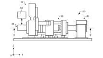
まず、第1実施形態に係る射出成形装置について、図面を参照しながら説明する。図1は、第1実施形態に係る射出成形装置100を模式的に示す図である。なお、図1では、互いに直交する3軸として、X軸、Y軸、およびZ軸を示している。X軸方向およびY軸方向は、例えば、水平方向である。Z軸方向は、例えば、鉛直方向である。 1. First embodiment 1.1. Injection molding apparatus 1.1.1. Overall configuration First, an injection molding apparatus according to a first embodiment will be described with reference to the drawings. FIG. 1 is a diagram that shows a schematic diagram of an
射出成形装置100は、図1に示すように、材料供給部10と、射出部20と、型部30と、型締部40と、制御部50と、を含む。As shown in FIG. 1, the
材料供給部10は、射出部20に原料となる材料を供給する。材料供給部10は、例えば、ホッパーによって構成されている。材料供給部10には、ペレット状や粉末状の材料が供給される。The
射出部20は、材料供給部10から供給された材料を可塑化して、溶融材料にする。そして、射出部20は、溶融材料を型部30に向けて射出する。The
なお、可塑化とは、溶融を含む概念であり、固体から流動性を有する状態に変化させることである。具体的には、ガラス転移が起こる材料の場合、可塑化とは、材料の温度をガラス転移点以上にすることである。ガラス転移が起こらない材料の場合、可塑化とは、材料の温度を融点以上にすることである。Plasticization is a concept that includes melting, and refers to changing a material from a solid to a fluid state. Specifically, for materials that undergo glass transition, plasticization refers to raising the temperature of the material above the glass transition point. For materials that do not undergo glass transition, plasticization refers to raising the temperature of the material above the melting point.
型部30には、成形品の形状に相当するキャビティーが形成される。射出部20から射出された溶融材料は、キャビティーに流れ込む。そして、溶融材料が冷却されて固化され、成形品が生成される。A cavity corresponding to the shape of the molded product is formed in the
型締部40は、型部30の開閉を行う。型締部40は、溶融材料が冷却された固化された後に、型部30を開く。これにより、成形品が外部に排出される。The
制御部50は、例えば、プロセッサーと、主記憶装置と、外部との信号の入出力を行う入出力インターフェースと、を有するコンピューターによって構成されている。制御部50は、例えば、主記憶装置に読み込んだプログラムをプロセッサーが実行することによって、種々の機能を発揮する。具体的には、制御部50は、射出部20および型締部40を制御する。なお、制御部50は、コンピューターではなく、複数の回路の組み合わせによって構成されてもよい。The
1.1.2. 具体的な構成
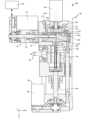
図2は、射出成形装置100を模式的に示す図1のII-II線断面図である。射出部20は、図2に示すように、例えば、可塑化装置60と、射出機構70と、ノズル80と、を有している。 2 is a cross-sectional view taken along line II-II in FIG. 1, which illustrates a schematic diagram of the
可塑化装置60は、材料供給部10から供給された材料を可塑化し、流動性を有するペースト状の溶融材料を生成して射出機構70へと導くように構成されている。可塑化装置60は、例えば、スクリューケース62と、駆動モーター64と、フラットスクリュー110と、バレル120と、ヒーター130と、逆止弁140と、を有している。The
スクリューケース62は、フラットスクリュー110を収容する筐体である。スクリューケース62とバレル120とによって囲まれた空間に、フラットスクリュー110が収容されている。The
駆動モーター64は、スクリューケース62に設けられている。駆動モーター64は、フラットスクリュー110を回転させる。駆動モーター64は、制御部50によって制御される。The
フラットスクリュー110は、回転軸RA方向の大きさが、回転軸RA方向と直交する方向の大きさよりも小さい略円柱形状を有している。図示の例では、回転軸RAは、Y軸と平行である。駆動モーター64が発生させるトルクによって、フラットスクリュー110は、回転軸RAを中心に回転する。フラットスクリュー110は、主面111と、主面111とは反対側の溝形成面112と、主面111と溝形成面112とを接続する接続面
113と、を有している。ここで、図3は、フラットスクリュー110を模式的に示す斜視図である。なお、便宜上、図3では、図2に示した状態とは上下の位置関係を逆向きとした状態を示している。また、図2では、フラットスクリュー110を簡略化して図示している。 The
フラットスクリュー110の溝形成面112には、図3に示すように、第1溝114が形成されている。第1溝114は、例えば、溝中央部115と、溝接続部116と、材料導入部117と、を有している。溝中央部115は、バレル120に設けられた連通孔126と対向している。溝中央部115は、連通孔126と連通している。溝接続部116は、溝中央部115と材料導入部117とを接続している。図示の例では、溝接続部116は、溝中央部115から溝形成面112の外周に向かって渦状に設けられている。材料導入部117は、溝形成面112の外周に設けられている。すなわち、材料導入部117は、フラットスクリュー110の接続面113に設けられている。材料供給部10から供給された材料は、材料導入部117から第1溝114に導入され、溝接続部116および溝中央部115を通って、バレル120に設けられた連通孔126に搬送される。図示の例では、第1溝114は、2つ設けられている。3, a
なお、第1溝114の数は、特に限定されない。図示はしないが、第1溝114は、3つ以上設けられていてもよいし、1つだけ設けられていてもよい。The number of
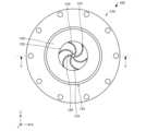
バレル120は、図2に示すように、フラットスクリュー110に対向して設けられている。バレル120は、フラットスクリュー110の溝形成面112に対向する対向面122を有している。対向面122の中心には、連通孔126が設けられている。ここで、図4は、バレル120を模式的に示す図である。なお、便宜上、図2では、バレル120を簡略化して図示している。As shown in FIG. 2, the
バレル120の対向面122には、図4に示すように、第2溝124と、連通孔126と、が設けられている。第2溝124は、複数設けられている。図示の例では、6つの第2溝124が設けられているが、その数は、特に限定されない。複数の第2溝124は、Y軸方向からみて、連通孔126の周りに設けられている。第2溝124は、一端が連通孔126に接続され、連通孔126から対向面122の外周に向かって渦状に延びている。第2溝124は、溶融材料を連通孔126に導く機能を有している。As shown in FIG. 4, the opposing
なお、第2溝124の形状は、特に限定されず、例えば、直線状であってもよい。また、第2溝124の一端は、連通孔126に接続されていなくてもよい。さらに、第2溝124は、対向面122に設けられていなくてもよい。ただし、連通孔126に溶融材料を効率よく導くことを考慮すると、第2溝124は、対向面122に設けられていることが好ましい。The shape of the
ヒーター130は、図2に示すように、バレル120に設けられている。図示の例では、ヒーター130は、バレル120に設けられた4本の棒ヒーターによって構成されている。ヒーター130は、フラットスクリュー110とバレル120との間に供給された材料を加熱する。ヒーター130の出力は、制御部50によって制御される。可塑化装置60は、フラットスクリュー110、バレル120、およびヒーター130によって、材料を連通孔126に向かって搬送しながら加熱して溶融材料を生成し、生成された溶融材料を、連通孔126から射出機構70へと流出させる。The
逆止弁140は、連通孔126に設けられている。逆止弁140は、連通孔126からフラットスクリュー110に設けられた第1溝114へ溶融材料が逆流することを抑制することができる。The
射出機構70は、例えば、シリンダー72と、プランジャー74と、プランジャー駆動部76と、を有している。シリンダー72は、連通孔126に接続された略円筒状の部材である。プランジャー74は、シリンダー72の内部を移動する。プランジャー74は、モーターやギア等によって構成されたプランジャー駆動部76によって駆動される。プランジャー駆動部76は、制御部50によって制御される。The
射出機構70は、プランジャー74をシリンダー72内で摺動させることによって、計量操作および射出操作を実行する。計量操作とは、連通孔126から離れる-X軸方向にプランジャー74を移動させることによって、連通孔126に位置する溶融材料をシリンダー72内へと導いて、シリンダー72内において計量する操作を指す。射出操作とは、連通孔126へ近付く+X軸方向にプランジャー74を移動させることによって、シリンダー72内の溶融材料を、ノズル80を介して型部30に射出する操作を指す。The
ノズル80には、連通孔126と連通しているノズル孔82が設けられている。ノズル孔82は、可塑化装置60から供給された溶融材料を型部30の成形型32に射出する。具体的には、上述した計量操作および射出操作が実行されることによって、シリンダー72内で計量された溶融材料が、射出機構70から連通孔126を介してノズル孔82へと送られる。そして、溶融材料は、ノズル孔82から型部30へと射出される。The
型部30は、成形型32を有している。成形型32は、金型である。ノズル孔82に送られた溶融材料は、ノズル孔82から成形型32のキャビティー34に射出される。具体的には、成形型32は、互いに対向する可動型36および固定型38を有し、可動型36と固定型38との間にキャビティー34を有している。キャビティー34は、成形品の形状に相当する空間である。可動型36および固定型38の材質は、金属である。なお、可動型36および固定型38の材質は、セラミック、樹脂であってもよい。The
型締部40は、例えば、型駆動部42と、ボールねじ部44と、を有している。型駆動部42は、例えば、モーター、ギアなどによって構成されている。型駆動部42は、ボールねじ部44を介して可動型36に接続されている。型駆動部42の駆動は、制御部50によって制御される。ボールねじ部44は、型駆動部42の駆動による動力を可動型36に伝達する。型締部40は、型駆動部42およびボールねじ部44によって可動型36を移動させることによって、型部30の開閉を行う。The
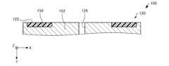
1.1.3. バレルの第1部材および第2部材
図5は、バレル120を模式的に示す図4のV-V線断面図である。バレル120は、図4および図5に示すように、第1部材150と、第2部材152と、を有している。 1.1.3 First and second members of barrel Fig. 5 is a cross-sectional view taken along line VV in Fig. 4, which illustrates a schematic view of the
第1部材150は、連通孔126と離間して設けられている。第1部材150は、バレル120の対向面122が表面処理されて形成されている。例えば、金属からなる円盤状の第2部材152の一部を削り、削られた部分に第1部材150を嵌め込むことにより、第1部材150が形成されている。第1部材150は、Y軸方向からみて、連通孔126を囲む形状を有している。図4に示す例では、第1部材150の形状は、リング状である。The
なお、例えば、第1部材150は、第2部材152の一部をコーティングすることによって形成されていてもよい。このように、「表面処理」とは、ある部材を削ることや、ある部材にコーティングをすることなどを含む。For example, the
第1部材150の材質は、例えば、PEEK(ポリエーテルエーテルケトン)、PBI
(ポリベンゾイミダゾール)、ABS(アクリロニトリル・ブタジエン・スチレン)樹脂などの樹脂である。第1部材150の融点は、材料供給部10から供給される材料の融点より高い。例えば、材料供給部10から供給された材料がABSの場合、第1部材150の材質は、PEEK、PBIなどである。例えば、材料供給部10から供給された材料がPEEKの場合、第1部材150の材質は、PBIなどである。 The material of the
(polybenzimidazole), ABS (acrylonitrile butadiene styrene) resin, or other resin. The melting point of the
第2部材152は、第1部材150と連通孔126との間に設けられている。第1部材150よりも連通孔126の近くに第2部材152が設けられている。図4および図5に示す例では、第2部材152は、第1部材150の内側、第1部材150の外側、および第1部材150の+Y軸方向に設けられている。連通孔126は、第2部材152に設けられている。第2部材152は、Y軸方向からみて、連通孔126を囲む形状を有している。The
第2部材152の熱伝導率は、第1部材150の熱伝導率と異なる。具体的には、第1部材150の熱伝導率は、第2部材152の熱伝導率よりも低い。第2部材152の材質は、例えば、SUS(ステンレス鋼)などの金属である。The thermal conductivity of the
第1部材150の熱伝導率と第2部材152の熱伝導率との差は、例えば、材料供給部10から供給される材料が非晶性の場合よりも結晶性の場合の方が、小さい。換言すると、供給される材料が非晶性の場合は、第1部材150の熱伝導率と第2部材152の熱伝導率との差が第1差Δ1となるように、部材150,152の材質を選択する。供給される材料が結晶性の場合は、第1部材150の熱伝導率と第2部材152の熱伝導率との差が第1差Δ1よりも小さい第2差Δ2となるように、部材150,152の材質を選択する。非晶性の材料としては、例えば、ABS樹脂が挙げられる。結晶性の樹脂としては、例えば、PEEKが挙げられる。The difference between the thermal conductivity of the
Y軸方向からみて、第1部材150の面積は、例えば、材料供給部10から供給される材料が非晶性の場合よりも結晶性の場合の方が、小さい。換言すると、供給される材料が非晶性の場合は、第1部材150の面積が第1面積S1となるように、第1部材150を設ける。供給される材料が結晶性の場合は、第1部材150の面積が第1面積S1よりも小さい第2面積S2となるように、第1部材150を設ける。When viewed in the Y-axis direction, the area of the
なお、Y軸方向からみて、第2部材152の面積は、例えば、材料供給部10から供給される材料が非晶性の場合よりも結晶性の場合の方が、大きくてもよい。また、供給される材料が非晶性の場合、第1部材150の面積は、第2部材152の面積より大きくてもよく、供給される材料が結晶性の場合、第1部材150の面積は、第2部材152の面積より小さくてもよい。When viewed in the Y-axis direction, the area of the
第2部材152には、第2溝124が設けられている。第1部材150には、第2溝124は、設けられていない。第1部材150は熱伝導率が低いため、ヒーター130の熱を供給された材料に伝達し難く、材料が溶融し難い。そのため、第1部材150に第2溝124を設けても、連通孔126に溶融材料を導き難い。第1部材150は、ヒーター130と離間している。第2部材152は、例えば、ヒーター130と接している。第1部材150とヒーター130との間には、第2部材152が設けられている。The
図示の例では、第1部材150の外側に、第2部材152が設けられている。図示はしないが、バレル120の外周側には、冷却管が設けられている。そのため、第1部材150の外側に熱伝導率の高い第2部材152を設けることにより、第1部材150の外側の部分の温度を下げることができる。In the illustrated example, the
1.1.4. フラットスクリューの表面粗さ
図6は、フラットスクリュー110を模式的に示す図である。フラットスクリュー110は、図6に示すように、外周部110aと、中央部110bと、を有している。外周部110aは、フラットスクリュー110に設けられた第1溝114の材料導入部117を含む部分である。図示の例では、外周部110aの形状は、リング状である。中央部110bは、第1溝114の溝中央部115を含む部分である。図示の例では、中央部110bの形状は、円である。図示の例では、外周部110aと中央部110bとの境界線Bは、Y軸方向からみて、フラットスクリュー110の外周と、フラットスクリュー110の中心と、の中点を結んで形成される曲線である。 1.1.4. Surface Roughness of the Flat Screw FIG. 6 is a diagram showing a
第1溝114の内面118の表面粗さRaは、フラットスクリュー110の外周部110aの方が中央部110bよりも大きい。内面118は、第1溝114を規定するフラットスクリュー110の面である。内面118は、底面118aと、側面118bと、を有している。ここで、「内面118の表面粗さRaは、外周部110aの方が中央部110bよりも大きい」とは、底面118aおよび側面118bの少なくとも一方の表面粗さRaにおいて、外周部110aの方が中央部110bよりも大きいことをいう。底面118aおよび側面118bは、例えば、互いに直交している。The surface roughness Ra of the
外周部110aにおける内面118の表面粗さRaは、例えば、1.0μmよりも大きい。中央部110bにおける内面118の表面粗さRaは、例えば、0.5μmよりも小さい。表面粗さRaは、例えば、AFM(Atomic Force Microscope)によって測定することができる。The surface roughness Ra of the
上記のような表面粗さRaを有するフラットスクリュー110は、例えば、以下のようにして形成される。フラットスクリュー110を加工して第1溝114を形成した後、中央部110bを磨き、外周部110aを磨かないことにより、外周部110aと中央部110bとで表面粗さRaに差をつけることができる。または、フラットスクリュー110を加工して第1溝114を形成した後、中央部110bをマスク層で覆い、外周部110aをブラスト加工することによって、外周部110aと中央部110bとで表面粗さRaに差をつけることができる。フラットスクリュー110の材質は、例えば、SUSである。The
1.1.5. 作用効果
可塑化装置60では、バレル120は、第1部材150と、第1部材150と熱伝導率が異なる第2部材152と、を有し、第1部材150よりも連通孔126の近くに第2部材152が設けられている。そのため、可塑化装置60では、例えば第1部分の熱伝導率と第2部分の熱伝導率とが同じ場合に比べて、連通孔126の温度とバレル120の外周の温度との差をつけ易い。これにより、可塑化装置60では、バレル120の外周から連通孔126に向けて温度勾配を適切に制御することができ、安定化した可塑化を実現することができる。 1.1.5. Effects In the
可塑化装置60では、第1部材150の熱伝導率は、第2部材152の熱伝導率よりも低い。そのため、可塑化装置60では、バレル120の外周から連通孔126に向けて温度が高くなる温度勾配を形成し易い。In the
可塑化装置60では、第1部材150および第2部材152は、連通孔126を囲む形状を有する。そのため、可塑化装置60では、第1部材および第2部材が連通孔を囲む形状を有さない場合に比べて、バレル120の外周から連通孔126に向けて温度勾配を形成し易い。In the
可塑化装置60では、第1部材150は、対向面122が表面処理されて形成されている。そのため、可塑化装置60では、例えば第1部材を他の部材に溶接することなく、第1部材150および第2部材152を有するバレル120を形成することができる。In the
なお、図示はしないが、第1部材150の代わりに第2部材152が表面処理されて形成されていてもよいし、第1部材150および第2部材152の両方が表面処理されて形成されていてもよい。Although not shown, the
可塑化装置60では、第1部材150の熱伝導率と第2部材152の熱伝導率との差は、材料が非晶性の場合よりも結晶性の場合の方が、小さい。材料が結晶性の場合は、材料が非晶性の場合よりも可塑化し難い。そのため、可塑化装置60では、材料が結晶性の場合は、材料が非晶性の場合よりも第1部材150の熱伝導率を第2部材152の熱伝導率に近づけて、バレル120の外周でも材料に熱を伝わり易くすることにより、可塑化の促進を図ることができる。このように、可塑化装置60では、第1部材150および第2部材152の少なくとも一方の材質を変更することで、材料に適した温度勾配を形成することができる。例えば、供給される材料がエラストマーであっても、容易に温度制御することができる。そのため、射出量を増大させることができる。In the
可塑化装置60では、駆動モーター64の回転軸RA方向からみて、第1部材150の面積は、材料が非晶性の場合よりも結晶性の場合の方が、小さい。上記のとおり、材料が結晶性の場合は、材料が非晶性の場合よりも可塑化し難い。そのため、可塑化装置60では、材料が結晶性の場合は、材料が非晶性の場合よりも第1部材150の面積を小さくして、バレル120の外周でも材料に熱を伝わり易くすることにより、可塑化の促進を図ることができる。このように、可塑化装置60では、第1部材150の面積を変更することで、材料に適した温度勾配を形成することができる。In the
可塑化装置60では、第1溝114の内面118の表面粗さRaは、フラットスクリュー110の外周部110aの方が中央部110bよりも大きい。例えば、フラットスクリューの外周部の表面粗さRaが中央部以下であると、外周部において材料がフラットスクリューに吸着し、連通孔に材料を搬送できない場合がある。特に、材料がエラストマーやMIM(Multilayer Instruction Model)材の場合は、このような現象が起きやすい。In the
上記のような問題に対し、可塑化装置60では、外周部110aの内面118の表面粗さRaを、中央部110bの内面118の表面粗さRaよりも大きくすることにより、材料とフラットスクリュー110との接触面積を小さくして材料の吸着を抑制し、材料を連通孔126に搬送することができる。表面粗さRaが大きいと、例えば、材料は、内面118の表面を構成する2つの凸部の間に位置する凹部に入り込まないので、材料とフラットスクリュー110との接触面積を小さくすることができる。さらに、材料のフラットスクリュー110に対する吸着を抑制できるので、射出量のばらつきを抑制することができる。In response to the above problems, in the
さらに、可塑化装置60では、中央部110bの内面118の表面粗さRaを、外周部110aの内面118の表面粗さRaよりも小さくすることにより、溶融された状態の材料を、スムーズに連通孔126に搬送することができる。Furthermore, in the
2. 第2実施形態
2.1. 射出成形装置
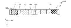
次に、第2実施形態に係る射出成形装置について、図面を参照しながら説明する。図7は、第2実施形態に係る射出成形装置200のバレル120を模式的に示す断面図である。 2. Second embodiment 2.1 Injection molding apparatus Next, an injection molding apparatus according to a second embodiment will be described with reference to the drawings. Fig. 7 is a cross-sectional view that shows a schematic view of a
以下、第2実施形態に係る射出成形装置200において、上述した第1実施形態に係る射出成形装置100の構成部材と同様の機能を有する部材については同一の符号を付し、その詳細な説明を省略する。In the following, in the
上述した射出成形装置100では、図5に示すように、第1部材150は、対向面122が表面処理されて形成されていた。In the above-described
これに対し、射出成形装置200では、図7に示すように、第1部材150は、表面処理によって形成されていない。第1部材150は、例えば、他の部材に溶接されることによって形成されている。In contrast, in the
射出成形装置200では、バレル120は、第1部材150と、第2部材152と、第3部材154と、を有している。図示の例では、第3部材154は、Y軸方向からみて、第1部材150と第2部材152との間に設けられた第1部分154aと、第2部材152と連通孔126との間に設けられた第2部分154bと、を有している。第1部分154aの熱伝導率は、例えば、第1部材150の熱伝導率よりも高く、かつ、第2部材152の熱伝導率よりも低い。第2部分154bの熱伝導率は、例えば、第2部材152の熱伝導率よりも高い。第1部分154aおよび第2部分154bの材質は、特に限定されない。In the
2.2. 変形例
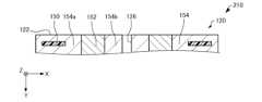
次に、第2実施形態の変形例に係る射出成形装置について、図面を参照しながら説明する。図8は、第2実施形態の変形例に係る射出成形装置210のバレル120を模式的に示す断面図である。以下、第2実施形態の変形例に係る射出成形装置210において、上述した第2実施形態に係る射出成形装置200の構成部材と同様の機能を有する部材については同一の符号を付し、その詳細な説明を省略する。 2.2. Modifications Next, an injection molding apparatus according to a modification of the second embodiment will be described with reference to the drawings. Fig. 8 is a cross-sectional view showing a
上述した射出成形装置200では、図7に示すように、第1部材150は、バレル120の対向面122を形成していた。In the above-described
これに対し、射出成形装置210では、図8に示すように、第1部材150は、対向面122を形成しておらず、第3部材154に囲まれて設けられている。第1部材150は、第3部材154に挟まれている。第1部材150は、対向面122とヒーター130との間に設けられている。第2部材152は、対向面122とヒーター130との間に設けられている。In contrast, in the
なお、材料供給部10から供給される材料としては、熱可塑性を有する材料、金属材料、セラミック材料等の種々の材料を主材料とした材料を挙げることができる。ここで、「主材料」とは、成形品の形状を形作っている中心となる材料を意味し、成形品において50重量%以上の含有率を占める材料を意味する。上述した材料には、それらの主材料を単体で溶融したものや、主材料とともに含有される一部の成分が溶融してペースト状にされたものが含まれる。The materials supplied from the
熱可塑性を有する材料としては、例えば、熱可塑性樹脂を用いることができる。熱可塑性樹脂としては、例えば、ABS樹脂、ポリプロピレン(PP)、ポリエチレン(PE)、ポリアセタール(POM )、ポリ塩化ビニル(PVC)、ポリアミド(PA)、ポリ乳酸(PLA)、ポリフェニレンサルファイド(PPS)、ポリカーボネート(PC)、変性ポリフェニレンエーテル、ポリブチレンテレフタレート、ポリエチレンテレフタレートなどの汎用エンジニアリングプラスチック、ポリサルフォン、ポリエーテルサルフォン
、ポリフェニレンサルファイド、ポリアリレート、ポリイミド、ポリアミドイミド、ポリエーテルイミド、PEEKなどのエンジニアリングプラスチックが挙げられる。 Examples of the material having thermoplastic properties include thermoplastic resins, such as general-purpose engineering plastics, such as ABS resin, polypropylene (PP), polyethylene (PE), polyacetal (POM), polyvinyl chloride (PVC), polyamide (PA), polylactic acid (PLA), polyphenylene sulfide (PPS), polycarbonate (PC), modified polyphenylene ether, polybutylene terephthalate, and polyethylene terephthalate, and engineering plastics, such as polysulfone, polyethersulfone, polyphenylene sulfide, polyarylate, polyimide, polyamideimide, polyetherimide, and PEEK.
熱可塑性を有する材料には、顔料や、金属、セラミック、その他に、ワックス、難燃剤、酸化防止剤、熱安定剤などの添加剤等が混入されていてもよい。熱可塑性を有する材料は、可塑化装置60において、フラットスクリュー110の回転と、ヒーター130の加熱と、によって可塑化されて溶融した状態に転化される。また、そのように生成された溶融材料は、ノズル80から射出された後、温度の低下によって硬化する。熱可塑性を有する材料は、そのガラス転移点以上に加熱されて完全に溶融した状態でノズル80から射出されることが望ましい。The thermoplastic material may contain pigments, metals, ceramics, and additives such as wax, flame retardants, antioxidants, and heat stabilizers. The thermoplastic material is plasticized and converted to a molten state in the
可塑化装置60では、上述した熱可塑性を有する材料の代わりに、例えば、金属材料が主材料として用いられてもよい。この場合には、金属材料を粉末状にした粉末材料に、造形材料の生成の際に溶融する成分が混合されて、可塑化装置60に投入されることが望ましい。In the
金属材料としては、例えば、マグネシウム(Mg)、鉄(Fe)、コバルト(Co)やクロム(Cr)、アルミニウム (Al)、チタン(Ti)、銅(Cu)、ニッケル(Ni)の単一の金属、もしくはこれらの金属を1つ以上含む合金、また、マルエージング鋼、ステンレス鋼、コバルトクロムモリブデン、チタニウム合金、ニッケル合金、アルミニウム合金、コバルト合金、コバルトクロム合金が挙げられる。Metallic materials include, for example, a single metal such as magnesium (Mg), iron (Fe), cobalt (Co), chromium (Cr), aluminum (Al), titanium (Ti), copper (Cu), or nickel (Ni), or an alloy containing one or more of these metals, as well as maraging steel, stainless steel, cobalt-chromium-molybdenum, titanium alloy, nickel alloy, aluminum alloy, cobalt alloy, and cobalt-chromium alloy.
可塑化装置60においては、上記の金属材料の代わりに、セラミック材料を主材料として用いることが可能である。セラミック材料としては、例えば、二酸化ケイ素、二酸化チタン、酸化アルミニウム、酸化ジルコニウムなどの酸化物セラミックや、窒化アルミニウムなどの非酸化物セラミックなどが挙げられる。In the
材料供給部10から供給される金属材料やセラミック材料の粉末材料は、単一の金属の粉末や合金の粉末、セラミック材料の粉末を、複数種類、混合した混合材料であってもよい。また、金属材料やセラミック材料の粉末材料は、例えば、上述の熱可塑性樹脂、あるいは、それ以外の熱可塑性樹脂によってコーティングされていてもよい。この場合には、可塑化装置60において、その熱可塑性樹脂が溶融して流動性が発現されるものとしてもよい。The powder material of the metallic material or ceramic material supplied from the
材料供給部10から供給される金属材料やセラミック材料の粉末材料には、例えば、溶剤を添加することもできる。溶剤としては、例えば、水;エチレングリコールモノメチルエーテル、エチレングリコールモノエチルエーテル、プロピレングリコールモノメチルエーテル、プロピレングリコールモノエチルエーテル等の(ポリ)アルキレングリコールモノアルキルエーテル類;酢酸エチル、酢酸n-プロピル、酢酸iso-プロピル、酢酸n-ブチル、酢酸iso-ブチル等の酢酸エステル類;ベンゼン、トルエン、キシレン等の芳香族炭化水素類;メチルエチルケトン、アセトン、メチルイソブチルケトン、エチル-n-ブチルケトン、ジイソプロピルケトン、アセチルアセトン等のケトン類;エタノール、プロパノール、ブタノール等のアルコール類;テトラアルキルアンモニウムアセテート類;ジメチルスルホキシド、ジエチルスルホキシド等のスルホキシド系溶剤;ピリジン、γ-ピコリン、2,6-ルチジン等のピリジン系溶剤;テトラアルキルアンモニウムアセテート(例えば、テトラブチルアンモニウムアセテート等);ブチルカルビトールアセテート等のイオン液体等が挙げられる。For example, a solvent may be added to the powder material of the metal material or ceramic material supplied from the
その他に、材料供給部10から供給される金属材料やセラミック材料の粉末材料には、例えば、バインダーが添加されていてもよい。バインダーとしては、例えば、アクリル樹
脂、エポキシ樹脂、シリコーン樹脂、セルロース系樹脂或いはその他の合成樹脂またはPLA(ポリ乳酸)、PA(ポリアミド)、PPS(ポリフェニレンサルファイド)、PEEK、あるいはその他の熱可塑性樹脂が挙げられる。 In addition, for example, a binder may be added to the powder material of the metal material or ceramic material supplied from the
3. 第3実施形態
次に、第3実施形態に係る三次元造形装置について、図面を参照しながら説明する。図9は、本実施形態に係る三次元造形装置300を模式的に示す断面図である。 3. Third embodiment Next, a three-dimensional modeling apparatus according to a third embodiment will be described with reference to the drawings. Fig. 9 is a cross-sectional view that illustrates a three-
三次元造形装置300は、例えば、図9に示すように、材料供給部10と、制御部50と、可塑化装置60と、ノズル80と、ステージ310と、移動機構320と、を含む。可塑化装置60は、例えば、スクリューケース62と、駆動モーター64と、フラットスクリュー110と、バレル120と、ヒーター130と、を有している。As shown in FIG. 9, the three-
ノズル80は、可塑化装置60から供給された溶融材料をステージ310に向かって吐出させる。具体的には、三次元造形装置300は、ノズル80からステージ310に溶融材料を吐出させつつ、移動機構320を駆動して、ノズル80とステージ310との相対的な位置を変化させる。これにより、三次元造形装置300は、ステージ310上に所望の形状の三次元造形物を造形する。The
ステージ310は、移動機構320によって移動される。三次元造形物は、ステージ310の造形面312に形成される。なお、ステージ310上に直接的に溶融材料が積層されてもよいが、ステージ310上に試料プレートを設け、試料プレート上に三次元造形物が形成されてもよい。The
移動機構320は、ノズル80とステージ310との相対的な位置を変化させる。図示の例では、移動機構320は、ノズル80に対して、ステージ310を移動させる。移動機構320は、例えば、3つのモーター322の駆動力によって、ステージ310をX軸方向、Y軸方向、およびZ軸方向に移動させる3軸ポジショナーによって構成される。モーター322は、制御部50によって制御される。The moving
なお、移動機構320は、ステージ310を移動させずに、ノズル80を移動させる構成であってもよい。または、移動機構320は、ノズル80およびステージ310の両方を移動させる構成であってもよい。The moving
上述した実施形態および変形例は一例であって、これらに限定されるわけではない。例えば、各実施形態および各変形例を適宜組み合わせることも可能である。The above-described embodiment and modified examples are merely examples, and the present invention is not limited to these. For example, each embodiment and each modified example can be combined as appropriate.
本発明は、実施の形態で説明した構成と実質的に同一の構成、例えば、機能、方法及び結果が同一の構成、あるいは目的及び効果が同一の構成を含む。また、本発明は、実施の形態で説明した構成の本質的でない部分を置き換えた構成を含む。また、本発明は、実施の形態で説明した構成と同一の作用効果を奏する構成又は同一の目的を達成することができる構成を含む。また、本発明は、実施の形態で説明した構成に公知技術を付加した構成を含む。The present invention includes configurations that are substantially the same as the configurations described in the embodiments, for example configurations with the same functions, methods and results, or configurations with the same purpose and effect. The present invention also includes configurations in which non-essential parts of the configurations described in the embodiments are replaced. The present invention also includes configurations that achieve the same effects as the configurations described in the embodiments, or configurations that can achieve the same purpose. The present invention also includes configurations in which publicly known technology is added to the configurations described in the embodiments.
上述した実施形態から以下の内容が導き出される。The following can be derived from the above-described embodiment:
可塑化装置の一態様は、
材料を可塑化する可塑化装置であって、
駆動モーターと、
前記駆動モーターによって回転し、溝が形成された溝形成面を有するスクリューと、
前記溝形成面に対向する対向面を有し、ヒーターおよび連通孔が設けられたバレルと、を含み、
前記バレルは、
第1部材と、
前記第1部材と熱伝導率が異なる第2部材と、
を有し、
前記第1部材よりも前記連通孔の近くに前記第2部材が設けられている。 One embodiment of the plasticizer comprises:
A plasticizing device for plasticizing a material, comprising:
A drive motor;
a screw that is rotated by the drive motor and has a groove forming surface on which grooves are formed;
a barrel having an opposing surface facing the groove forming surface, the barrel being provided with a heater and a communication hole;
The barrel comprises:
A first member;
A second member having a thermal conductivity different from that of the first member;
having
The second member is provided closer to the communication hole than the first member.
この可塑化装置によれば、安定化した可塑化を実現することができる。This plasticizer allows for stable plasticization.
前記可塑化装置の一態様において、
前記第1部材の熱伝導率は、前記第2部材の熱伝導率よりも低くてもよい。 In one embodiment of the plasticizing device,
The first member may have a lower thermal conductivity than the second member.
この可塑化装置によれば、バレルの外周から連通孔に向けて温度が高くなる温度勾配を形成し易い。This plasticizer makes it easy to create a temperature gradient in which the temperature increases from the outer periphery of the barrel toward the connecting holes.
前記可塑化装置の一態様において、
前記第1部材および前記第2部材は、前記連通孔を囲む形状を有してもよい。 In one embodiment of the plasticizing device,
The first member and the second member may have a shape surrounding the communication hole.
この可塑化装置によれば、第1部材および第2部材が連通孔を囲む形状を有さない場合に比べて、バレルの外周から連通孔に向けて温度勾配を形成し易い。With this plasticizer, it is easier to create a temperature gradient from the outer periphery of the barrel toward the communicating hole, compared to when the first and second members do not have a shape that surrounds the communicating hole.
前記可塑化装置の一態様において、
前記第1部材および前記第2部材の少なくとも一方は、前記対向面が表面処理されて形成されていてもよい。 In one embodiment of the plasticizing device,
At least one of the first member and the second member may be formed such that the opposing surface is surface-treated.
この可塑化装置では、例えば第1部材を他の部材に溶接することなく、第1部材および第2部材を有するバレルを形成することができる。With this plasticizing device, for example, a barrel having a first member and a second member can be formed without welding the first member to another member.
前記可塑化装置の一態様において、
前記第1部材の熱伝導率と前記第2部材の熱伝導率との差は、前記材料が非晶性の場合よりも結晶性の場合の方が、小さくてもよい。 In one embodiment of the plasticizing device,
The difference between the thermal conductivity of the first member and the thermal conductivity of the second member may be smaller when the material is crystalline than when the material is amorphous.
この可塑化装置によれば、材料に適した温度勾配を形成することができる。This plasticizer allows you to create a temperature gradient that is suitable for the material.
前記可塑化装置の一態様において、
前記駆動モーターの回転軸方向からみて、前記第1部材の面積は、前記材料が非晶性の場合よりも結晶性の場合の方が、小さくてもよい。 In one embodiment of the plasticizing device,
The area of the first member as viewed from the direction of the rotation axis of the drive motor may be smaller when the material is crystalline than when the material is amorphous.
この可塑化装置によれば、材料に適した温度勾配を形成することができる。This plasticizer allows you to create a temperature gradient that is suitable for the material.
前記可塑化装置の一態様において、
前記溝の内面の表面粗さは、前記スクリューの外周部の方が中央部よりも大きくてもよい。 In one embodiment of the plasticizing device,
The surface roughness of the inner surface of the groove may be greater at the outer periphery of the screw than at the center.
この可塑化装置によれば、材料のスクリューに対する吸着を抑制し、材料を連通孔に搬送することができる。This plasticizer can prevent the material from sticking to the screw and transport the material to the connecting holes.
射出成形装置の一態様は、
材料を可塑化して溶融材料にする可塑化装置と、
前記可塑化装置から供給された前記溶融材料を成形型に射出するノズルと、
を含み、
前記可塑化装置は、
駆動モーターと、
前記駆動モーターによって回転し、溝が形成された溝形成面を有するスクリューと、
前記溝形成面に対向する対向面を有し、ヒーターおよび連通孔が設けられたバレルと、を含み、
前記バレルは、
第1部材と、
前記第1部材と熱伝導率が異なる第2部材と、
を有し、
前記第1部材よりも前記連通孔の近くに前記第2部材が設けられている。 One embodiment of the injection molding apparatus comprises:
a plasticizer for plasticizing the material into a molten material;
a nozzle for injecting the molten material supplied from the plasticizer into a mold;
Including,
The plasticizing device comprises:
A drive motor;
a screw that is rotated by the drive motor and has a groove forming surface on which grooves are formed;
a barrel having an opposing surface facing the groove forming surface, the barrel being provided with a heater and a communication hole;
The barrel comprises:
A first member;
A second member having a thermal conductivity different from that of the first member;
having
The second member is provided closer to the communication hole than the first member.
三次元造形装置の一態様は、
材料を可塑化して溶融材料にする可塑化装置と、
前記可塑化装置から供給された前記溶融材料をステージに向かって吐出させるノズルと、
を含み、
前記可塑化装置は、
駆動モーターと、
前記駆動モーターによって回転し、溝が形成された溝形成面を有するスクリューと、
前記溝形成面に対向する対向面を有し、ヒーターおよび連通孔が設けられたバレルと、を含み、
前記バレルは、
第1部材と、
前記第1部材と熱伝導率が異なる第2部材と、
を有し、
前記第1部材よりも前記連通孔の近くに前記第2部材が設けられている。 One aspect of the three-dimensional printing apparatus includes:
a plasticizer for plasticizing the material into a molten material;
a nozzle for ejecting the molten material supplied from the plasticizer toward a stage;
Including,
The plasticizing device comprises:
A drive motor;
a screw that is rotated by the drive motor and has a groove forming surface on which grooves are formed;
a barrel having an opposing surface facing the groove forming surface, the barrel being provided with a heater and a communication hole;
The barrel comprises:
A first member;
A second member having a thermal conductivity different from that of the first member;
having
The second member is provided closer to the communication hole than the first member.
10…材料供給部、20…射出部、30…型部、32…成形型、34…キャビティー、36…可動型、38…固定型、40…型締部、42…型駆動部、44…ボールねじ部、50…制御部、60…可塑化装置、62…スクリューケース、64…駆動モーター、70…射出機構、72…シリンダー、74…プランジャー、76…プランジャー駆動部、80…ノズル、82…ノズル孔、100…射出成形装置、110…フラットスクリュー、111…主面、112…溝形成面、113…接続面、114…第1溝、115…溝中央部、116…溝接続部、117…材料導入部、118…内面、118a…底面、118b…側面、120…バレル、122…対向面、124…第2溝、126…連通孔、130…ヒーター、140…逆止弁、150…第1部材、152…第2部材、154…第3部材、154a…第1部分、154b…第2部分、200…射出成形装置、300…三次元造形装置、310…ステージ、312…造形面、320…移動機構、322…モーター10...material supply section, 20...injection section, 30...mold section, 32...molding mold, 34...cavity, 36...movable mold, 38...fixed mold, 40...mold clamping section, 42...mold drive section, 44...ball screw section, 50...control section, 60...plasticizing device, 62...screw case, 64...drive motor, 70...injection mechanism, 72...cylinder, 74...plunger, 76...plunger drive section, 80...nozzle, 82...nozzle hole, 100...injection molding device, 110...flat screw, 111...main surface, 112...groove forming surface, 113... Connection surface, 114...first groove, 115...groove center, 116...groove connection, 117...material introduction section, 118...inner surface, 118a...bottom surface, 118b...side surface, 120...barrel, 122...opposing surface, 124...second groove, 126...communication hole, 130...heater, 140...check valve, 150...first member, 152...second member, 154...third member, 154a...first part, 154b...second part, 200...injection molding device, 300...three-dimensional modeling device, 310...stage, 312...modeling surface, 320...movement mechanism, 322...motor
Claims (8)
Translated fromJapanese駆動モーターと、
前記駆動モーターによって回転し、溝が形成された溝形成面を有するスクリューと、
前記溝形成面に対向する対向面を有し、ヒーターおよび連通孔が設けられたバレルと、を含み、
前記バレルは、
第1部材と、
前記第1部材と熱伝導率が異なる第2部材と、
を有し、
前記第1部材よりも前記連通孔の近くに前記第2部材が設けられ、
前記第1部材および前記第2部材の少なくとも一方は、前記対向面が表面処理されて形成されている、可塑化装置。 A plasticizing device for plasticizing a material, comprising:
A drive motor;
a screw that is rotated by the drive motor and has a groove forming surface on which grooves are formed;
a barrel having an opposing surface facing the groove forming surface, the barrel being provided with a heater and a communication hole;
The barrel comprises:
A first member;
A second member having a thermal conductivity different from that of the first member;
having
The second member is provided closer to the communication hole than the first member,
At least one of the first member and the second member has an opposing surface that is surface-treated .
駆動モーターと、
前記駆動モーターによって回転し、溝が形成された溝形成面を有するスクリューと、
前記溝形成面に対向する対向面を有し、ヒーターおよび連通孔が設けられたバレルと、を含み、
前記バレルは、
第1部材と、
前記第1部材と熱伝導率が異なる第2部材と、
を有し、
前記第1部材よりも前記連通孔の近くに前記第2部材が設けられ、
前記第1部材の熱伝導率と前記第2部材の熱伝導率との差は、前記材料が非晶性の場合よりも結晶性の場合の方が、小さい、可塑化装置。 A plasticizing device for plasticizing a material, comprising:
A drive motor;
a screw that is rotated by the drive motor and has a groove forming surface on which grooves are formed;
a barrel having an opposing surface facing the groove forming surface, the barrel being provided with a heater and a communication hole;
The barrel comprises:
A first member;
A second member having a thermal conductivity different from that of the first member;
having
The second member is provided closer to the communication hole than the first member,
A plasticizing apparatus, wherein a difference between the thermal conductivity of the first member and the thermal conductivity of the second member is smaller when the material is crystalline than when the material is amorphous .
駆動モーターと、
前記駆動モーターによって回転し、溝が形成された溝形成面を有するスクリューと、
前記溝形成面に対向する対向面を有し、ヒーターおよび連通孔が設けられたバレルと、を含み、
前記バレルは、
第1部材と、
前記第1部材と熱伝導率が異なる第2部材と、
を有し、
前記第1部材よりも前記連通孔の近くに前記第2部材が設けられ、
前記駆動モーターの回転軸方向からみて、前記第1部材の面積は、前記材料が非晶性の場合よりも結晶性の場合の方が、小さい、可塑化装置。 A plasticizing device for plasticizing a material, comprising:
A drive motor;
a screw that is rotated by the drive motor and has a groove forming surface on which grooves are formed;
a barrel having an opposing surface facing the groove forming surface, the barrel being provided with a heater and a communication hole;
The barrel comprises:
A first member;
A second member having a thermal conductivity different from that of the first member;
having
The second member is provided closer to the communication hole than the first member,
A plasticizing device, wherein an area of the first member as viewed from a direction of a rotation axis of the drive motor is smaller when the material is crystalline than when the material is amorphous .
駆動モーターと、
前記駆動モーターによって回転し、溝が形成された溝形成面を有するスクリューと、
前記溝形成面に対向する対向面を有し、ヒーターおよび連通孔が設けられたバレルと、を含み、
前記バレルは、
第1部材と、
前記第1部材と熱伝導率が異なる第2部材と、
を有し、
前記第1部材よりも前記連通孔の近くに前記第2部材が設けられ、
前記溝の内面の表面粗さは、前記スクリューの外周部の方が中央部よりも大きい、可塑化装置。 A plasticizing device for plasticizing a material, comprising:
A drive motor;
a screw that is rotated by the drive motor and has a groove forming surface on which grooves are formed;
a barrel having an opposing surface facing the groove forming surface, the barrel being provided with a heater and a communication hole;
The barrel comprises:
A first member;
A second member having a thermal conductivity different from that of the first member;
having
The second member is provided closer to the communication hole than the first member,
A plasticizing device, wherein the surface roughness of the inner surface of the groove is greater at the outer periphery of the screw than at the central portion .
前記第1部材の熱伝導率は、前記第2部材の熱伝導率よりも低い、可塑化装置。 Inany one of claims 1 to 4 ,
The thermal conductivity of the first member is lower than the thermal conductivity of the second member.
前記第1部材および前記第2部材は、前記連通孔を囲む形状を有する、可塑化装置。 Inany one of claims 1 to 5 ,
The first member and the second member have a shape surrounding the communication hole.
前記可塑化装置から供給された前記溶融材料を成形型に射出するノズルと、
を含む、射出成形装置。A plasticizing device accordingto any one of claims 1 to 6 , which plasticizes the material to form amolten material;
a nozzle for injecting the molten material supplied from the plasticizer into a mold;
1. An injection molding apparatuscomprising :
前記可塑化装置から供給された前記溶融材料をステージに向かって吐出させるノズルと、
を含む、三次元造形装置。
A plasticizing device accordingto any one of claims 1 to 6 , which plasticizes the material to form amolten material;
a nozzle for ejecting the molten material supplied from the plasticizer toward a stage;
A three-dimensional printing apparatuscomprising :
Priority Applications (3)
| Application Number | Priority Date | Filing Date | Title |
|---|---|---|---|
| JP2020194250AJP7585737B2 (en) | 2020-11-24 | 2020-11-24 | Plasticizing equipment, injection molding equipment, and 3D modeling equipment |
| CN202111385083.7ACN114536689B (en) | 2020-11-24 | 2021-11-22 | Plasticizing device, injection molding device, and three-dimensional molding device |
| US17/455,940US11731331B2 (en) | 2020-11-24 | 2021-11-22 | Plasticizing apparatus, injection molding apparatus, and three-dimensional shaping apparatus |
Applications Claiming Priority (1)
| Application Number | Priority Date | Filing Date | Title |
|---|---|---|---|
| JP2020194250AJP7585737B2 (en) | 2020-11-24 | 2020-11-24 | Plasticizing equipment, injection molding equipment, and 3D modeling equipment |
Publications (2)
| Publication Number | Publication Date |
|---|---|
| JP2022083026A JP2022083026A (en) | 2022-06-03 |
| JP7585737B2true JP7585737B2 (en) | 2024-11-19 |
Family
ID=81658995
Family Applications (1)
| Application Number | Title | Priority Date | Filing Date |
|---|---|---|---|
| JP2020194250AActiveJP7585737B2 (en) | 2020-11-24 | 2020-11-24 | Plasticizing equipment, injection molding equipment, and 3D modeling equipment |
Country Status (3)
| Country | Link |
|---|---|
| US (1) | US11731331B2 (en) |
| JP (1) | JP7585737B2 (en) |
| CN (1) | CN114536689B (en) |
Citations (2)
| Publication number | Priority date | Publication date | Assignee | Title |
|---|---|---|---|---|
| JP2010000752A (en) | 2008-06-23 | 2010-01-07 | Canon Electronics Inc | Plasticizing feeder and injection molding machine equipped with the same |
| JP2019202458A (en) | 2018-05-23 | 2019-11-28 | セイコーエプソン株式会社 | Plasticizing apparatus, injection molding machine and molding apparatus |
Family Cites Families (32)
| Publication number | Priority date | Publication date | Assignee | Title |
|---|---|---|---|---|
| US2705342A (en) | 1949-05-18 | 1955-04-05 | Tube Turns Plastics Inc | Injection molding machine |
| JPS4982754A (en) | 1972-12-12 | 1974-08-09 | ||
| US3866669A (en) | 1972-12-13 | 1975-02-18 | Crompton & Knowles Corp | Extruder and temperature control apparatus therefor |
| US3954366A (en) | 1975-01-06 | 1976-05-04 | Fields Reuben T | Two-stage single screw extrusion apparatus |
| US4531308A (en) | 1983-04-29 | 1985-07-30 | Cactus Machinery Inc. | Apparatus for conditioning hygroscopic plastic material |
| US5121329A (en) | 1989-10-30 | 1992-06-09 | Stratasys, Inc. | Apparatus and method for creating three-dimensional objects |
| JP3052603B2 (en) | 1992-09-17 | 2000-06-19 | 三菱マテリアル株式会社 | Porous metal bond whetstone |
| JPH0970864A (en) | 1995-09-08 | 1997-03-18 | Sumitomo Heavy Ind Ltd | Injection device |
| JPH10249892A (en) | 1997-03-07 | 1998-09-22 | Molex Inc | Electric heating nozzle |
| JP3345360B2 (en) | 1998-10-22 | 2002-11-18 | 住友重機械工業株式会社 | Injection equipment |
| US6146575A (en)* | 1999-02-08 | 2000-11-14 | Husky Injection Molding Systems Ltd. | Apparatus and method for plasticization and extrusion employing an orbital scroll |
| BR0213265A (en) | 2001-10-18 | 2004-10-26 | Community Entpr Llc | Multilayer Injection Molding Machine |
| JP2004314399A (en) | 2003-04-15 | 2004-11-11 | Toshiba Mach Co Ltd | Temperature adjusting device of molding machine |
| US7972129B2 (en) | 2005-09-16 | 2011-07-05 | O'donoghue Joseph | Compound tooling system for molding applications |
| JP2009269182A (en)* | 2008-04-30 | 2009-11-19 | Canon Electronics Inc | Plasticization and delivery device for molding material and injection molding machine using it |
| JP2010241016A (en) | 2009-04-07 | 2010-10-28 | Canon Electronics Inc | Plasticizing feeder, rotor for the same and injection molding machine using the same |
| WO2011082238A1 (en) | 2009-12-29 | 2011-07-07 | Synventive Molding Solutions, Inc. | Heating apparatus for fluid flow channel |
| CN202264379U (en)* | 2011-11-24 | 2012-06-06 | 佛山新长盛塑料薄膜有限公司 | Screw of polymer extruder |
| JP5859345B2 (en) | 2012-03-08 | 2016-02-10 | 住友重機械工業株式会社 | Injection molding machine |
| PL3112133T3 (en) | 2014-02-25 | 2021-01-11 | Seiichi YUYAMA | 3d printer |
| CA3054231C (en) | 2015-08-12 | 2022-05-17 | Omachron Intellectual Property Inc. | Mold having a pressurization member |
| US20170291364A1 (en) | 2016-04-11 | 2017-10-12 | Timothy W. Womer | Single screw micro-extruder for 3d printing |
| US10449719B2 (en) | 2017-12-01 | 2019-10-22 | Bulent Besim | System for feeding filament to a nozzle in an additive manufacturing machine |
| WO2019141606A1 (en) | 2018-01-16 | 2019-07-25 | Universiteit Gent | An extruder with axial displacement |
| US11235526B2 (en)* | 2018-11-07 | 2022-02-01 | Seiko Epson Corporation | Plasticizing device, three-dimensional modeling device, and injection molding device |
| JP2020075397A (en) | 2018-11-07 | 2020-05-21 | セイコーエプソン株式会社 | Plasticization device, three-dimensional molding device and injection molding device |
| JP7272047B2 (en)* | 2019-03-27 | 2023-05-12 | セイコーエプソン株式会社 | Plasticizing device and three-dimensional modeling device |
| JP7375358B2 (en) | 2019-08-01 | 2023-11-08 | セイコーエプソン株式会社 | Plasticizing equipment, three-dimensional modeling equipment and injection molding equipment |
| JP2021024147A (en) | 2019-08-01 | 2021-02-22 | セイコーエプソン株式会社 | Plasticization device and three-dimensional shaping device |
| JP7326976B2 (en) | 2019-08-01 | 2023-08-16 | セイコーエプソン株式会社 | Plasticizing equipment, three-dimensional modeling equipment and injection molding equipment |
| CN211516164U (en)* | 2019-08-30 | 2020-09-18 | 合肥学鼎机电科技有限公司 | Hardware material surface drilling device |
| JP7516869B2 (en) | 2020-05-28 | 2024-07-17 | セイコーエプソン株式会社 | Plasticizing device, injection molding device, and three-dimensional modeling device |
- 2020
- 2020-11-24JPJP2020194250Apatent/JP7585737B2/enactiveActive
- 2021
- 2021-11-22CNCN202111385083.7Apatent/CN114536689B/enactiveActive
- 2021-11-22USUS17/455,940patent/US11731331B2/enactiveActive
Patent Citations (2)
| Publication number | Priority date | Publication date | Assignee | Title |
|---|---|---|---|---|
| JP2010000752A (en) | 2008-06-23 | 2010-01-07 | Canon Electronics Inc | Plasticizing feeder and injection molding machine equipped with the same |
| JP2019202458A (en) | 2018-05-23 | 2019-11-28 | セイコーエプソン株式会社 | Plasticizing apparatus, injection molding machine and molding apparatus |
Also Published As
| Publication number | Publication date |
|---|---|
| CN114536689B (en) | 2024-09-13 |
| US20220161476A1 (en) | 2022-05-26 |
| CN114536689A (en) | 2022-05-27 |
| US11731331B2 (en) | 2023-08-22 |
| JP2022083026A (en) | 2022-06-03 |
Similar Documents
| Publication | Publication Date | Title |
|---|---|---|
| US11235526B2 (en) | Plasticizing device, three-dimensional modeling device, and injection molding device | |
| CN110524821A (en) | Plasticizing apparatus, injection (mo(u)lding) machine and styling apparatus | |
| US11648719B2 (en) | Plasticization device, three-dimensional shaping device, and injection molding device | |
| JP7375358B2 (en) | Plasticizing equipment, three-dimensional modeling equipment and injection molding equipment | |
| JP7608778B2 (en) | 3D modeling equipment | |
| CN113547733B (en) | Plasticizing device, three-dimensional modeling device, and injection molding device | |
| JP7683334B2 (en) | Plasticizing equipment, injection molding equipment, and 3D modeling equipment | |
| JP7585737B2 (en) | Plasticizing equipment, injection molding equipment, and 3D modeling equipment | |
| JP7491038B2 (en) | Plasticizing device, 3D modeling device, and injection molding device | |
| JP7400410B2 (en) | plasticizing equipment | |
| JP7613018B2 (en) | Plasticizing equipment and injection molding equipment | |
| JP7658162B2 (en) | Plasticizing device, 3D modeling device, and injection molding device | |
| JP7371398B2 (en) | Plasticizing equipment, three-dimensional modeling equipment and injection molding equipment | |
| JP7512661B2 (en) | Plasticizing device, 3D modeling device, and injection molding device | |
| JP2025085260A (en) | Plasticizing equipment, injection molding equipment, and 3D modeling equipment | |
| JP2024107710A (en) | Plasticizing equipment, injection molding equipment, and 3D modeling equipment | |
| JP7722017B2 (en) | injection molding equipment | |
| JP2025153225A (en) | Plasticizing equipment, three-dimensional modeling equipment, and injection molding equipment | |
| JP2025006923A (en) | Material Discharge Device | |
| JP2023158737A (en) | Plasticizing equipment, injection molding equipment, and three-dimensional printing equipment | |
| JP2024078705A (en) | Injection Molding Equipment | |
| JP2024084388A (en) | Method for evaluating molds and injection molding equipment | |
| CN118849317A (en) | Material ejection device, injection molding device | |
| JP2024108324A (en) | Material supply device and plasticizer | |
| JP2023083726A (en) | Injection molding apparatus and injection molding method |
Legal Events
| Date | Code | Title | Description |
|---|---|---|---|
| A621 | Written request for application examination | Free format text:JAPANESE INTERMEDIATE CODE: A621 Effective date:20230905 | |
| A977 | Report on retrieval | Free format text:JAPANESE INTERMEDIATE CODE: A971007 Effective date:20240801 | |
| A131 | Notification of reasons for refusal | Free format text:JAPANESE INTERMEDIATE CODE: A131 Effective date:20240813 | |
| A521 | Request for written amendment filed | Free format text:JAPANESE INTERMEDIATE CODE: A523 Effective date:20240913 | |
| TRDD | Decision of grant or rejection written | ||
| A01 | Written decision to grant a patent or to grant a registration (utility model) | Free format text:JAPANESE INTERMEDIATE CODE: A01 Effective date:20241008 | |
| A61 | First payment of annual fees (during grant procedure) | Free format text:JAPANESE INTERMEDIATE CODE: A61 Effective date:20241021 | |
| R150 | Certificate of patent or registration of utility model | Ref document number:7585737 Country of ref document:JP Free format text:JAPANESE INTERMEDIATE CODE: R150 |