JP7585351B2 - Augmented and virtual reality display system with correlated incoupling and outcoupling optical regions - Patents.com - Google Patents
Augmented and virtual reality display system with correlated incoupling and outcoupling optical regions - Patents.comDownload PDFInfo
- Publication number
- JP7585351B2 JP7585351B2JP2022570304AJP2022570304AJP7585351B2JP 7585351 B2JP7585351 B2JP 7585351B2JP 2022570304 AJP2022570304 AJP 2022570304AJP 2022570304 AJP2022570304 AJP 2022570304AJP 7585351 B2JP7585351 B2JP 7585351B2
- Authority
- JP
- Japan
- Prior art keywords
- light
- waveguide
- display system
- regions
- eye
- Prior art date
- Legal status (The legal status is an assumption and is not a legal conclusion. Google has not performed a legal analysis and makes no representation as to the accuracy of the status listed.)
- Active
Links
Images


Classifications
- G—PHYSICS
- G02—OPTICS
- G02B—OPTICAL ELEMENTS, SYSTEMS OR APPARATUS
- G02B27/00—Optical systems or apparatus not provided for by any of the groups G02B1/00 - G02B26/00, G02B30/00
- G02B27/01—Head-up displays
- G02B27/017—Head mounted
- G02B27/0172—Head mounted characterised by optical features
- G—PHYSICS
- G02—OPTICS
- G02B—OPTICAL ELEMENTS, SYSTEMS OR APPARATUS
- G02B27/00—Optical systems or apparatus not provided for by any of the groups G02B1/00 - G02B26/00, G02B30/00
- G02B27/0093—Optical systems or apparatus not provided for by any of the groups G02B1/00 - G02B26/00, G02B30/00 with means for monitoring data relating to the user, e.g. head-tracking, eye-tracking
- G—PHYSICS
- G02—OPTICS
- G02B—OPTICAL ELEMENTS, SYSTEMS OR APPARATUS
- G02B6/00—Light guides; Structural details of arrangements comprising light guides and other optical elements, e.g. couplings
- G02B6/0001—Light guides; Structural details of arrangements comprising light guides and other optical elements, e.g. couplings specially adapted for lighting devices or systems
- G02B6/0011—Light guides; Structural details of arrangements comprising light guides and other optical elements, e.g. couplings specially adapted for lighting devices or systems the light guides being planar or of plate-like form
- G02B6/0013—Means for improving the coupling-in of light from the light source into the light guide
- G02B6/0015—Means for improving the coupling-in of light from the light source into the light guide provided on the surface of the light guide or in the bulk of it
- G02B6/0016—Grooves, prisms, gratings, scattering particles or rough surfaces
- G—PHYSICS
- G02—OPTICS
- G02B—OPTICAL ELEMENTS, SYSTEMS OR APPARATUS
- G02B6/00—Light guides; Structural details of arrangements comprising light guides and other optical elements, e.g. couplings
- G02B6/0001—Light guides; Structural details of arrangements comprising light guides and other optical elements, e.g. couplings specially adapted for lighting devices or systems
- G02B6/0011—Light guides; Structural details of arrangements comprising light guides and other optical elements, e.g. couplings specially adapted for lighting devices or systems the light guides being planar or of plate-like form
- G02B6/0075—Arrangements of multiple light guides
- G02B6/0076—Stacked arrangements of multiple light guides of the same or different cross-sectional area
- G—PHYSICS
- G02—OPTICS
- G02B—OPTICAL ELEMENTS, SYSTEMS OR APPARATUS
- G02B27/00—Optical systems or apparatus not provided for by any of the groups G02B1/00 - G02B26/00, G02B30/00
- G02B27/01—Head-up displays
- G02B27/0101—Head-up displays characterised by optical features
- G02B2027/0123—Head-up displays characterised by optical features comprising devices increasing the field of view
- G02B2027/0125—Field-of-view increase by wavefront division
- G—PHYSICS
- G02—OPTICS
- G02B—OPTICAL ELEMENTS, SYSTEMS OR APPARATUS
- G02B26/00—Optical devices or arrangements for the control of light using movable or deformable optical elements
- G02B26/08—Optical devices or arrangements for the control of light using movable or deformable optical elements for controlling the direction of light
- G02B26/10—Scanning systems
- G02B26/105—Scanning systems with one or more pivoting mirrors or galvano-mirrors
Landscapes
- Physics & Mathematics (AREA)
- General Physics & Mathematics (AREA)
- Optics & Photonics (AREA)
- Diffracting Gratings Or Hologram Optical Elements (AREA)
Description
Translated fromJapanese(関連出願の相互参照)
あらゆる出願であって、それに関して外国または国内の優先権の主張が、本願とともに出願された出願データシート内で識別されるものは、37 CFR 1.57下、参照することによって本明細書に組み込まれる。CROSS-REFERENCE TO RELATED APPLICATIONS
Any application to which a claim of foreign or domestic priority is made that is identified in an Application Data Sheet filed herewith is hereby incorporated by reference under 37 CFR 1.57.
本願は、その内容は、参照することによってその全体として本明細書に組み込まれる、2020年5月22日に出願され、「METHOD AND SYSTEM FOR DUAL PROJECTOR WAVEGUIDE DISPLAYS WITH WIDE FIELD OF VIEW」と題された、米国仮特許出願第63/029312号、および2020年7月10日に出願され、「AUGMENTED AND VIRTUAL REALITY DISPLAY SYSTEMS WITH CORRELATED IN-COUPLING AND OUT-COUPLING OPTICAL REGIONS FOR EFFICIENT LIGHT UTILIZATION」と題された、米国仮特許出願第63/050635号の優先権を主張する。This application is a joint venture between U.S. Provisional Patent Application No. 63/029,312, filed May 22, 2020 and entitled "METHOD AND SYSTEM FOR DUAL PROJECTOR WAVEGUIDE DISPLAYS WITH WIDE FIELD OF VIEW," the contents of which are incorporated herein by reference in their entirety, and U.S. Provisional Patent Application No. 63/029,312, filed July 10, 2020 and entitled "AUGMENTED AND VIRTUAL REALITY DISPLAY SYSTEMS WITH CORRELATED IN-COUPLING AND OUT-COUPLING OPTICAL REGIONS FOR EFFICIENT This application claims priority to U.S. Provisional Patent Application No. 63/050635, entitled "LIGHT UTILIZATION."
本願は、そのそれぞれの内容全体が、参照することによってその全体として本明細書に組み込まれる、2018年9月27日に公開され、「DEPTH BASED FOVEATED RENDERING FOR DISPLAY SYSTEMS」と題された、米国特許出願公開第2018/0275410号、「PERIOCULAR TEST FOR MIXED REALITY CALIBRATION」と題され、2020年2月25日に発行された、米国特許第10573042号、および「DISPLAY SYSTEMS AND METHODS FOR DETERMINING REGISTRATION BETWEEN A DISPLAY AND A USER’S EYES」と題された、2019年7月18日に公開された、米国特許出願公開第2019/0222830号、2019年5月21日に出願され、発行され、「IRIS BOUNDARY ESTIMATION USING CORNEA CURVATURE」と題された、米国特許第10,296,792号、2017年2月23日に公開され、「EYELID SHAPE ESTIMATION USING EYE POSE MEASUREMENT」と題された、米国特許公開第2017/0053165号、2017年2月23日に公開され、「EYELID SHAPE ESTIMATION」と題された、米国特許公開第2017/0053166号、2019年8月8日に公開され、「EYE CENTER OF ROTATION DETERMINATION, DEPTH PLANE SELECTION, AND RENDER CAMERA POSITIONING IN DISPLAY SYSTEMS」と題された、米国特許出願公開第2019/0243558号、2021年1月21日に公開され、「EYE CENTER OF ROTATION DETERMINATION WITH ONE OR MORE EYE TRACKING CAMERAS」と題された、国際公開第WO2021/01166号、2018年4月26日に公開され、「SYSTEM AND METHOD FOR PRESENTING IMAGE CONTENT ON MULIPLE DEPTH PLANES BY PROVIDING MULTIPLE INTRA-PUPIL PARALLAX VIEWS」と題された、米国特許出願公開第2018/0113311号、2019年9月12日に公開され、「DISPLAY SYSTEM WITH LOW-LATENCY PUPIL TRACKER」と題された、国際公開第WO2019/173158号、2017年10月12日に公開され、「AUGMENTED REALITY SYSTEMS AND METHODS WITH VARIABLE FOCUS LENS ELEMENTS」と題された、米国特許出願公開第2017/0293145号、および2018年4月26日に公開され、「SYSTEM AND METHOD FOR PRESENTING IMAGE CONTENT ON MULIPLE DEPTH PLANES BY PROVIDING MULTIPLE INTRA-PUPIL PARALLAX VIEWS」と題された、米国特許出願公開第2018/0113311号に関連する。This application is a continuation of U.S. Patent Application Publication No. 2018/0275410, published September 27, 2018 and entitled "DEPTH BASED FOVEATED RENDERING FOR DISPLAY SYSTEMS," U.S. Patent No. 10,573,042, published February 25, 2020 and entitled "PERIOCULAR TEST FOR MIXED REALITY CALIBRATION," and U.S. Patent No. 10,573,042, published February 25, 2020, the entire contents of each of which are incorporated herein by reference in their entirety. U.S. Patent Application Publication No. 2019/0222830, filed and issued on July 18, 2019, entitled "IRIS BOUNDARY ESTIMATION USING CORNEA CURVATION"; U.S. Patent Application Publication No. 10,296,792, filed and issued on May 21, 2019, entitled "EYELID SHAPE ESTIMATION USING EYE POSE MEASUREMENT"; U.S. Patent Application Publication No. 2017/0053165, filed and issued on February 23, 2017, entitled "EYELID SHAPE ESTIMATION USING EYE POSE MEASUREMENT"; U.S. Patent Publication No. 2017/0053166, published on August 8, 2019, entitled "EYE CENTER OF ROTATION DETERMINATION, DEPTH PLANE SELECTION, AND RENDER CAMERA POSITIONING IN DISPLAY SYSTEMS," and U.S. Patent Application Publication No. 2019/0243558, published on January 21, 2021, entitled "EYE CENTER OF ROTATION DETERMINATION WITH ONE OR MORE EYE TRACKING and U.S. Patent Application Publication No. 2018/0113311, published on September 12, 2019, entitled "DISPLAY SYSTEM WITH LOW-LATENCY PUPIL PARALLAX VIEWS," entitled "SYSTEM AND METHOD FOR PRESENTING IMAGE CONTENT ON MULTIPLE DEPTH PLANES BY PROVIDING MULTIPLE INTRA-PUPIL PARALLAX VIEWS." No. WO 2019/173158, published on Oct. 12, 2017, and entitled "AUGMENTED REALITY SYSTEMS AND METHODS WITH VARIABLE FOCUS LENS ELEMENTS," and U.S. Patent Application Publication No. 2017/0293145, published on April 26, 2018, and entitled "SYSTEM AND METHOD FOR PRESENTING IMAGE CONTENT ON MULIPLE DEPTH PLANES BY PROVIDING MULTIPLE INTRA-PUPILOT ELEMENTARY SYSTEMS AND METHODS WITH VARIABLE FOCUS LENS ELEMENTS," and This is related to U.S. Patent Application Publication No. 2018/0113311, entitled "PARALLAX VIEWS."
本開示は、ディスプレイシステムに関し、より具体的には、拡張および仮想現実ディスプレイシステムに関する。This disclosure relates to display systems, and more specifically to augmented and virtual reality display systems.
現代のコンピューティングおよびディスプレイ技術は、いわゆる「仮想現実」または「拡張現実」体験のためのシステムの開発を促進しており、デジタル的に再現された画像またはその一部が、現実であるように見える、すなわち、そのように知覚され得る様式でユーザに提示される。仮想現実、すなわち、「VR」シナリオは、典型的には、他の実際の実世界の視覚的入力に対する透過性を伴わずに、デジタルまたは仮想画像情報の提示を伴い、拡張現実、すなわち、「AR」シナリオは、典型的には、ユーザの周囲の実際の世界の可視化に対する拡張としてのデジタルまたは仮想画像情報の提示を伴う。複合現実、すなわち、「MR」シナリオは、一種のARシナリオであって、典型的には、自然世界の中に統合され、それに応答する、仮想オブジェクトを伴う。例えば、MRシナリオでは、実世界内のオブジェクトによって遮断されて見える、または別様にそれと相互作用するように知覚される、AR画像コンテンツを含んでもよい。Modern computing and display technologies have facilitated the development of systems for so-called "virtual reality" or "augmented reality" experiences, in which digitally reproduced images or portions thereof are presented to a user in a manner that appears, or can be perceived as, real. Virtual reality, or "VR", scenarios typically involve the presentation of digital or virtual image information without transparency to other actual real-world visual inputs, while augmented reality, or "AR", scenarios typically involve the presentation of digital or virtual image information as an augmentation to the visualization of the real world around the user. Mixed reality, or "MR", scenarios are a type of AR scenario that typically involve virtual objects that are integrated into and responsive to the natural world. For example, MR scenarios may include AR image content that appears occluded by or is otherwise perceived to interact with objects in the real world.
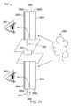
図1を参照すると、拡張現実場面10が、描写されている。AR技術のユーザには、人々、木々、背景における建物を特徴とする、実世界公園状設定20と、コンクリートプラットフォーム30とが見える。ユーザはまた、実世界プラットフォーム30上に立っているロボット像40と、マルハナバチの擬人化のように見える、飛んでいる漫画のようなアバタキャラクタ50等の「仮想コンテンツ」を「見ている」と知覚する。これらの要素50、40は、実世界には存在しないという点で、「仮想」である。ヒトの視知覚系は、複雑であって、他の仮想または実世界画像要素の中で仮想画像要素の快適で、自然のような感覚で、かつ豊かな提示を促進する、AR技術を生産することは、困難である。With reference to FIG. 1, an augmented
本明細書に開示されるシステムおよび方法は、ARまたはVR技術を含む、ディスプレイ技術に関連する種々の課題に対処する。The systems and methods disclosed herein address various challenges associated with display technologies, including AR or VR technologies.
本開示の側面が、ここで、図および種々の実施例に関して詳細に記載されるであろう。しかしながら、当業者は、本明細書に開示されるデバイスおよび方法の他の構成が、同程度に詳細に説明されない場合であっても、依然として、本開示の範囲内に該当するであろうことを理解するであろう。議論される種々の構成の側面は、本明細書の本開示の範囲を限定するものではなく、これは、代わりに、本説明に続く請求項によって定義される。Aspects of the present disclosure will now be described in detail with respect to figures and various examples. However, those skilled in the art will appreciate that other configurations of the devices and methods disclosed herein would still fall within the scope of the present disclosure even if not described in as much detail. The aspects of the various configurations discussed are not intended to limit the scope of the present disclosure herein, which is instead defined by the claims that follow this description.
下記に列挙される実施例等、光をユーザの1つまたはそれを上回る眼に投影し、仮想画像コンテンツを該ユーザの視野内に表示する、ディスプレイシステムの種々の実施例が、本明細書に説明される。Described herein are various embodiments of display systems that project light to one or more eyes of a user and display virtual image content within the user's field of view, such as the embodiments listed below.
実施例1:光を投影し、仮想画像コンテンツを表示するように構成される頭部搭載可能ディスプレイシステムであって、ディスプレイシステムは、光投影システムと、仮想画像コンテンツを表示するように構成される頭部搭載可能ディスプレイであって、頭部搭載可能ディスプレイは、少なくとも1つの導波管を含み、少なくとも1つの導波管は、複数の内部結合領域であって、複数の内部結合領域は、それぞれが、光投影システムから、仮想画像コンテンツを形成するための画像情報を有する光を受光し、光を導波管の中に内部結合するように構成される、複数の内部結合領域と、複数の外部結合領域であって、複数の外部結合領域は、光を導波管から外に外部結合し、仮想コンテンツを表示するように構成され、複数の外部結合領域のそれぞれは、内部結合領域の異なるものからの光を受光するように構成される、複数の外部結合領域とを備える、頭部搭載可能ディスプレイとを備える、ディスプレイシステム。Example 1: A head-mountable display system configured to project light and display virtual image content, the display system comprising: a light projection system; and a head-mountable display configured to display virtual image content, the head-mountable display including at least one waveguide, the at least one waveguide having a plurality of internal coupling regions, each of the plurality of internal coupling regions configured to receive light having image information for forming virtual image content from the light projection system and internally couple the light into the waveguide, and a plurality of external coupling regions, the plurality of external coupling regions configured to externally couple the light out of the waveguide and display the virtual content, each of the plurality of external coupling regions configured to receive light from a different one of the internal coupling regions.The display system.
実施例2:複数の内部結合領域の各内部結合領域は、複数の外部結合領域の一意の外部結合領域に対応し、選択的に光を指向するように構成される、実施例1に記載のディスプレイシステム。Example 2: A display system as described in Example 1, in which each of the multiple internal bonding regions corresponds to a unique external bonding region of the multiple external bonding regions and is configured to selectively direct light.
実施例3:各内部結合領域は、内部結合領域によって内部結合された光を内部結合領域に対応する外部結合領域によって優先的に外部結合させるように選択される傾斜、格子配向、格子構造サイズ、または格子ピッチのうちの少なくとも1つを有する回折格子である、実施例1または2に記載のディスプレイシステム。Example 3: A display system as described in Examples 1 or 2, wherein each internal coupling region is a diffraction grating having at least one of a tilt, a grating orientation, a grating structure size, or a grating pitch selected to preferentially outcouple light internally coupled by the internal coupling region through the external coupling region corresponding to the internal coupling region.
実施例4:光結合領域は、光投影システムからの入射光を、全内部反射のための角度において、導波管を通して、伝搬方向に沿って再指向するように構成され、光の一部を伝搬方向に交差する軸に沿って伝搬するように再指向するように構成される光分散構造をさらに備える、実施例1-3のいずれか1項に記載のディスプレイシステム。Example 4: A display system according to any one of Examples 1-3, wherein the light coupling region is configured to redirect incident light from the optical projection system along a propagation direction through the waveguide at an angle for total internal reflection, and further comprises a light dispersion structure configured to redirect a portion of the light to propagate along an axis intersecting the propagation direction.
実施例5:光分散構造および複数の外部結合領域は、少なくとも1つの導波管の対向主要表面上に配置される、実施例1-4のいずれか1項に記載のディスプレイシステム。Example 5: A display system as described in any one of Examples 1-4, in which the light dispersing structure and the multiple outcoupling regions are disposed on opposing major surfaces of at least one waveguide.
実施例6:複数の内部結合領域は、回折格子を備える、実施例1-5のいずれか1項に記載のディスプレイシステム。Example 6: A display system as described in any one of Examples 1-5, in which the multiple internal coupling regions include a diffraction grating.
実施例7:複数の内部結合領域のそれぞれは、導波管の少なくとも1つの他の内部結合領域と異なる格子ピッチを有する、実施例1-6のいずれか1項に記載のディスプレイシステム。Example 7: A display system as described in any one of Examples 1-6, in which each of the multiple internal coupling regions has a different grating pitch than at least one other internal coupling region of the waveguide.
実施例8:異なる格子ピッチは、導波管の中に内部結合された光が導波管に向かって全内部反射を受ける全内部反射角度を、複数の外部結合領域の関連付けられる外部結合領域に向かって変化させる、実施例1-7のいずれか1項に記載のディスプレイシステム。Example 8: A display system as described in any one of Examples 1-7, in which the different grating pitches change the total internal reflection angle at which light internally coupled into the waveguide undergoes total internal reflection toward the waveguide toward an associated outcoupling region of the plurality of outcoupling regions.
実施例9:複数の内部結合領域のそれぞれは、導波管の平面内に、導波管の少なくとも1つの他の内部結合領域と異なる格子配向を有する、実施例1-6のいずれか1項に記載のディスプレイシステム。Example 9: A display system as described in any one of Examples 1-6, in which each of the plurality of internal coupling regions has a different lattice orientation in the plane of the waveguide than at least one other internal coupling region of the waveguide.
実施例10:異なる格子配向は、光が複数の外部結合領域の意図される外部結合領域に向かって伝搬するように、光が導波管の中に結合される角度を変化させる、実施例1-9のいずれか1項に記載のディスプレイシステム。Example 10: A display system as described in any one of Examples 1-9, in which different grating orientations change the angle at which light is coupled into the waveguide such that the light propagates toward an intended outcoupling region of the multiple outcoupling regions.
実施例11:複数の内部結合領域のそれぞれは、導波管の平面に対して、導波管の少なくとも1つの他の内部結合領域と異なる傾斜を有する、実施例1-10のいずれか1項に記載のディスプレイシステム。Example 11: A display system according to any one of Examples 1-10, in which each of the plurality of internal coupling regions has a different inclination, relative to the plane of the waveguide, than at least one other internal coupling region of the waveguide.
実施例12:内部結合領域は、相互から離間される、実施例1-11のいずれか1項に記載のディスプレイシステム。Example 12: A display system according to any one of Examples 1-11, wherein the internal bonding regions are spaced apart from one another.
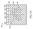
実施例13:光内部結合領域は、複数の外部結合領域の少なくとも1つの側の周囲に一列に配置される、実施例1-12のいずれか1項に記載のディスプレイシステム。Example 13: A display system as described in any one of Examples 1-12, in which the optical internal coupling regions are arranged in a line around at least one side of the plurality of external coupling regions.
実施例14:外部結合領域のそれぞれは、導波管を横断して、ストライプを画定し、ストライプは、内部結合領域の列に交差する軸に沿って伸長される、実施例1-13のいずれか1項に記載のディスプレイシステム。Example 14: A display system as described in any one of Examples 1-13, wherein each of the external coupling regions defines a stripe across the waveguide, the stripe extending along an axis that intersects the rows of the internal coupling regions.
実施例15:外部結合領域は、導波管を横断して、グリッドパターンを画定する、実施例1-14のいずれか1項に記載のディスプレイシステム。Example 15: A display system as described in any one of Examples 1-14, wherein the external coupling region defines a grid pattern across the waveguide.
実施例16:複数の内部結合領域のそれぞれは、光を内部結合し、その光を指向し、全内部反射によって、導波管の少なくとも1つの他の内部結合領域と異なる方向に沿って、導波管内で伝搬させるように配列される、実施例1-15のいずれか1項に記載のディスプレイシステム。Example 16: A display system as described in any one of Examples 1-15, wherein each of a plurality of internal coupling regions is arranged to internally couple light and direct the light to propagate within the waveguide by total internal reflection along a direction different from at least one other internal coupling region of the waveguide.
実施例17:少なくとも1つの外部結合領域の側方縁に近接する少なくとも1つの内部結合領域は、内向きにバイアスされた軸を中心として対称的に配置されるある角度の範囲に沿って、光を内部結合するように構成される、実施例1-16のいずれか1項に記載のディスプレイシステム。Example 17: A display system according to any one of Examples 1-16, wherein at least one internal coupling region proximate a lateral edge of at least one external coupling region is configured to internally couple light along a range of angles symmetrically disposed about an inwardly biased axis.
実施例18:複数の内部結合領域のうちの少なくとも2つは、複数の外部結合領域のうちの少なくとも1つの異なる側に沿って配置される、実施例1-17のいずれか1項に記載のディスプレイシステム。Example 18: A display system according to any one of Examples 1-17, wherein at least two of the plurality of internal bonding regions are disposed along different sides of at least one of the plurality of external bonding regions.
実施例19:複数の内部結合領域は、複数の外部結合領域のうちの少なくとも1つを囲繞する内部結合光学要素を、少なくとも3つの側上に備える、実施例1-18のいずれか1項に記載のディスプレイシステム。Example 19: A display system as described in any one of Examples 1-18, wherein the multiple internal bonding regions have internal bonding optical elements on at least three sides that surround at least one of the multiple external bonding regions.
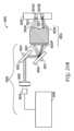
実施例20:光投影システムは、光源と、画像光を内部結合領域の個々のものに指向するように構成される可動光投入器とを備える、実施例1-19のいずれか1項に記載のディスプレイシステム。Example 20: A display system as described in any one of Examples 1-19, wherein the light projection system includes a light source and a movable light launcher configured to direct image light to individual ones of the internal coupling regions.
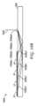
実施例21:頭部搭載可能ディスプレイは、導波管スタックを形成する複数の導波管を備え、導波管のそれぞれは、複数の内部結合領域および外部結合領域を備え、導波管のそれぞれの内部結合領域は、内部結合領域上に入射する内部結合光の方向から視認される際、真正面平面図に見られるように、側方に変位される、実施例1-20のいずれか1項に記載のディスプレイシステム。Example 21: A head-mountable display comprising a plurality of waveguides forming a waveguide stack, each of the waveguides comprising a plurality of internal coupling regions and external coupling regions, the internal coupling region of each of the waveguides being laterally displaced as seen in a front plan view when viewed from the direction of the internally coupled light incident on the internal coupling region, a display system as described in any one of Examples 1-20.
実施例22:同一導波管の外部結合領域は、同一波面発散を伴う光を出力するように構成され、異なる導波管の外部結合領域は、少なくとも1つの他の導波管の外部結合領域と異なる波面発散量を伴う光を出力するように構成され、異なる波面発散量は、異なる深度面に対応する、実施例1-21のいずれか1項に記載のディスプレイシステム。Example 22: A display system according to any one of Examples 1-21, in which the outcoupling regions of the same waveguide are configured to output light with the same wavefront divergence and the outcoupling regions of different waveguides are configured to output light with a different amount of wavefront divergence than the outcoupling regions of at least one other waveguide, the different amounts of wavefront divergence corresponding to different depth planes.
実施例23:各導波管の内部結合領域は、同一原色に対応する波長の範囲の光を内部結合するように構成され、いくつかの導波管の内部結合領域は、他の導波管の内部結合領域と異なる原色に対応する波長の範囲の光を内部結合するように構成される、実施例1-212のいずれか1項に記載のディスプレイシステム。Example 23: A display system according to any one of Examples 1-212, in which the internal coupling regions of each waveguide are configured to internally couple light in a range of wavelengths corresponding to the same primary color, and in which the internal coupling regions of some waveguides are configured to internally couple light in a range of wavelengths corresponding to different primary colors than the internal coupling regions of other waveguides.
実施例24:光投影システムは、光エミッタのアレイを備える光源と、光源からの光を変調させるように構成される空間光変調器と、フレーム上に搭載され、空間光変調器からの光を内部結合領域に指向するように構成される投影光学系とを備え、ディスプレイシステムは、異なる複数の光エミッタをアクティブ化し、仮想画像コンテンツを異なる深度面上に提供するように構成され、ディスプレイシステムは、仮想画像コンテンツを比較的に近深度面上に提供するために、複数の光エミッタの個々の光エミッタ間に比較的に大距離を提供することと、仮想画像コンテンツを比較的に遠深度面上に提供するために、複数の光エミッタの個々の光エミッタ間に比較的に小距離を提供することとを行うように構成される、実施例1-23のいずれか1項に記載のディスプレイシステム。Example 24: The display system according to any one of Examples 1-23, wherein the optical projection system includes a light source having an array of light emitters, a spatial light modulator configured to modulate light from the light source, and a projection optical system mounted on a frame and configured to direct light from the spatial light modulator to an internal coupling region, the display system is configured to activate different light emitters to provide virtual image content on different depth planes, and the display system is configured to provide a relatively large distance between individual light emitters of the multiple light emitters to provide virtual image content on a relatively near depth plane, and to provide a relatively small distance between individual light emitters of the multiple light emitters to provide virtual image content on a relatively far depth plane.
実施例25:複数の光エミッタの光エミッタのそれぞれを順次異なる時間にアクティブ化するように構成され、ディスプレイシステムは、各光エミッタのアクティブ化と異なる視差的に不同性の瞳孔内画像の表示を同期させるように構成される、実施例1-24のいずれか1項に記載のディスプレイシステム。Example 25: A display system as described in any one of Examples 1-24, configured to sequentially activate each of the light emitters of the plurality of light emitters at different times, and the display system configured to synchronize the activation of each light emitter with the display of different parallax-disparate intrapupillary images.
実施例26:光源は、マイクロディスプレイであり、光エミッタは、発光ダイオードである、実施例1-245のいずれか1項に記載のディスプレイシステム。Example 26: A display system according to any one of Examples 1-245, wherein the light source is a microdisplay and the light emitter is a light emitting diode.
実施例27:可変焦点レンズ要素を導波管の対向側上にさらに備える、実施例1-26のいずれか1項に記載のディスプレイシステム。Example 27: A display system according to any one of Examples 1-26, further comprising a variable focus lens element on the opposing side of the waveguide.
実施例28:光投影システムは、複数のプロジェクタを備え、複数のプロジェクタのプロジェクタは、頭部搭載型ディスプレイのFOVの細分割された部分以下のための画像コンテンツを提供するように構成される、実施例1-27のいずれか1項に記載のディスプレイシステム。Example 28: A display system as described in any one of Examples 1-27, wherein the optical projection system includes a plurality of projectors, each of the plurality of projectors configured to provide image content for at most a subdivided portion of the FOV of the head mounted display.
実施例29:ディスプレイシステムであって、光投影システムと、光をユーザの眼の中に投影し、仮想画像コンテンツを表示するように構成される頭部搭載可能ディスプレイであって、頭部搭載可能ディスプレイは、少なくとも1つの導波管であって、光投影システムからの光を受光するように構成される複数の光内部結合領域と、光をユーザの眼に出力するように構成される複数の光外部結合領域とを備える、少なくとも1つの導波管を備える、頭部搭載型ディスプレイと、ディスプレイおよび内向きに向いた結像システムと通信する処理電子機器であって、処理電子機器は、1つまたはそれを上回るプロセッサと、1つまたはそれを上回るコンピュータ記憶媒体とを備え、1つまたはそれを上回るコンピュータ記憶媒体は、命令を記憶しており、前記命令は、1つまたはそれを上回るプロセッサによって実行されると、1つまたはそれを上回るプロセッサに、眼の眼姿勢と関連付けられる光外部結合領域を決定することと、光投影システムからの光を、決定された光外部結合領域と関連付けられる光内部結合領域に指向するための命令を提供することとを含む動作を実施させる、処理電子機器とを備える、ディスプレイシステム。Example 29: A display system comprising: a light projection system; a head mountable display configured to project light into a user's eye and display virtual image content, the head mountable display comprising at least one waveguide, the head mountable display comprising a plurality of light in-coupling regions configured to receive light from the light projection system and a plurality of light out-coupling regions configured to output light to the user's eye; and processing electronics in communication with the display and an inwardly facing imaging system, the processing electronics comprising one or more processors and one or more computer storage media having instructions stored thereon that, when executed by the one or more processors, cause the one or more processors to perform operations including determining a light out-coupling region associated with an eye posture of the eye and providing instructions for directing light from the light projection system to the light in-coupling region associated with the determined light out-coupling region.
実施例30:光外部結合領域を決定することは、眼の通視線と複数の光外部結合領域のうちの1つの交点を決定することを含む、実施例29に記載のディスプレイシステム。Example 30: The display system of Example 29, wherein determining the light outcoupling area includes determining an intersection of the line of sight of the eye with one of the plurality of light outcoupling areas.
実施例31:光内部結合領域は、複数の外部結合領域の少なくとも1つの側の周囲に一列に配置される、実施例29または30に記載のディスプレイシステム。Example 31: A display system as described in Example 29 or 30, in which the optical internal coupling regions are arranged in a line around at least one side of the plurality of external coupling regions.
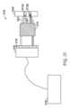
実施例32:光投影システムは、少なくとも1つの光源と、画像光を出力するように構成される、少なくとも1つの可動光投入器とを備える、実施例29に記載のディスプレイシステム。Example 32: A display system as described in Example 29, wherein the light projection system comprises at least one light source and at least one movable light emitter configured to output image light.
実施例33:少なくとも1つの可動光投入器は、走査式ミラーを備える、実施例29-32のいずれか1項に記載のディスプレイシステム。Example 33: A display system as described in any one of Examples 29-32, wherein at least one movable light emitter comprises a scanning mirror.
実施例34:少なくとも1つの可動光投入器は、走査式ファイバ投入器を備える、実施例29-33のいずれか1項に記載のディスプレイシステム。Example 34: A display system as described in any one of Examples 29-33, wherein at least one movable light launcher comprises a scanning fiber launcher.
実施例35:光投影システムは、少なくとも1つの光源と、光源からの光を変調させるように構成される少なくとも1つの空間光変調器とを備える、実施例29-34のいずれか1項に記載のディスプレイシステム。Example 35: A display system according to any one of Examples 29-34, wherein the optical projection system comprises at least one light source and at least one spatial light modulator configured to modulate light from the light source.
実施例36:頭部搭載型ディスプレイは、仮想オブジェクトを複数の深度面上に表示するように構成される、実施例29-35のいずれか1項に記載のディスプレイシステム。Example 36: A display system described in any one of Examples 29-35, wherein the head-mounted display is configured to display virtual objects on multiple depth planes.
実施例37:動作は、仮想オブジェクトの視差的に不同性の瞳孔内画像のセットを眼の中に投入し、仮想オブジェクトを深度面のうちの1つ上に表示することを含む、実施例29-36のいずれか1項に記載のディスプレイシステム。Example 37: A display system as described in any one of Examples 29-36, wherein the operations include projecting a set of parallax-dissimilar intrapupillary images of a virtual object into the eye and displaying the virtual object on one of the depth planes.
実施例38:動作は、視差的に不同性の瞳孔内画像のセットのそれぞれをフリッカ融合閾値内で投入することを含む、実施例29-37のいずれか1項に記載のディスプレイシステム。Example 38: A display system as described in any one of Examples 29-37, wherein the operation includes casting each of the set of parallax-dissimilar intra-pupillary images within a flicker fusion threshold.
実施例39:動作は、光を、決定された光外部結合領域と関連付けられる複数の内部結合領域の光内部結合領域内の複数の内部結合要素に指向するための命令を提供することを含む、実施例29-39のいずれか1項に記載のディスプレイシステム。Example 39: A display system as described in any one of Examples 29-39, wherein the operation includes providing instructions to direct light to a plurality of internal coupling elements within an optical internal coupling region of a plurality of internal coupling regions associated with the determined optical external coupling region.
実施例40:少なくとも1つの可変焦点レンズ要素を少なくとも1つの導波管のユーザ側上にさらに備え、第1の可変焦点レンズ要素は、投影された光を修正し、ユーザの眼の屈折異常を補正するように構成される、実施例29-39のいずれか1項に記載のディスプレイシステム。Example 40: The display system of any one of Examples 29-39, further comprising at least one variable focus lens element on a user side of at least one waveguide, the first variable focus lens element being configured to modify the projected light and correct for refractive error of the user's eye.
実施例41:動作はさらに、眼の固視点を決定し、固視点に対応する補正を適用することを含む、実施例29-40のいずれか1項に記載のディスプレイシステム。Example 41: A display system according to any one of Examples 29-40, wherein the operations further include determining an eye fixation point and applying a correction corresponding to the fixation point.
実施例42:ユーザの眼の1つまたはそれを上回る画像を捕捉するように構成される内向きに向いた結像システムをさらに備え、動作は、内向きに向いた結像システムによって捕捉されたユーザの眼の画像を受信することと、受信された画像に基づいて、眼姿勢を識別することとを含む、実施例29-41のいずれか1項に記載のディスプレイシステム。Example 42: A display system as described in any one of Examples 29-41, further comprising an inwardly facing imaging system configured to capture an image of one or more of the user's eyes, and operations include receiving an image of the user's eyes captured by the inwardly facing imaging system and identifying an eye posture based on the received image.
実施例43:少なくとも1つの導波管は、導波管スタックを形成する、複数の導波管のうちの1つであり、導波管のそれぞれは、複数の内部結合領域および外部結合領域を備え、導波管のそれぞれの内部結合領域は、内部結合領域上に入射する内部結合光の方向から視認される際、真正面平面図に見られるように、側方に変位される、実施例29-42のいずれか1項に記載のディスプレイシステム。Example 43: A display system according to any one of Examples 29-42, wherein at least one waveguide is one of a plurality of waveguides forming a waveguide stack, each of the waveguides having a plurality of internal and external coupling regions, and the internal coupling region of each of the waveguides is laterally displaced as seen in a front plan view when viewed from the direction of the internally coupled light incident on the internal coupling region.
実施例44:同一導波管の外部結合領域は、同一波面発散を伴う光を出力するように構成され、異なる導波管の外部結合領域は、少なくとも1つの他の導波管の外部結合領域と異なる波面発散量を伴う光を出力するように構成され、異なる波面発散量は、異なる深度面に対応する、実施例29-43のいずれか1項に記載のディスプレイシステム。Example 44: A display system according to any one of Examples 29-43, in which the outcoupling regions of the same waveguide are configured to output light with the same wavefront divergence and the outcoupling regions of different waveguides are configured to output light with a different amount of wavefront divergence than the outcoupling regions of at least one other waveguide, the different amounts of wavefront divergence corresponding to different depth planes.
実施例45:各導波管の内部結合領域は、同一原色に対応する波長の範囲の光を内部結合するように構成され、いくつかの導波管の内部結合領域は、他の導波管の内部結合領域と異なる原色に対応する波長の範囲の光を内部結合するように構成される、実施例29-44のいずれか1項に記載のディスプレイシステム。Example 45: A display system according to any one of Examples 29-44, in which the internal coupling regions of each waveguide are configured to internally couple light in a range of wavelengths corresponding to the same primary color, and in which the internal coupling regions of some waveguides are configured to internally couple light in a range of wavelengths corresponding to different primary colors than the internal coupling regions of other waveguides.
実施例46:光投影システムは、複数のプロジェクタを備え、複数のプロジェクタのプロジェクタは、頭部搭載型ディスプレイのFOVの細分割された部分以下のための画像コンテンツを提供するように構成される、実施例29-45のいずれか1項に記載のディスプレイシステム。Example 46: A display system as described in any one of Examples 29-45, wherein the optical projection system includes a plurality of projectors, each of the plurality of projectors configured to provide image content for at most a subdivided portion of the FOV of the head mounted display.
実施例47:ディスプレイシステムであって、光投影システムと、光をユーザの眼の中に投影し、仮想画像コンテンツを表示するように構成される頭部搭載型ディスプレイであって、頭部搭載型ディスプレイは、少なくとも1つの導波管であって、光投影システムからの光を受光するように構成される複数の光内部結合領域と、光をユーザの眼に出力するように構成される複数の光外部結合領域とを備える、少なくとも1つの導波管を備える、頭部搭載型ディスプレイと、ディスプレイと通信する処理電子機器であって、処理電子機器は、1つまたはそれを上回るプロセッサと、1つまたはそれを上回るコンピュータ記憶媒体とを備え、1つまたはそれを上回るコンピュータ記憶媒体は、命令を記憶しており、命令は、1つまたはそれを上回るプロセッサによって実行されると、1つまたはそれを上回るプロセッサに、ユーザの視野内の仮想オブジェクトのための場所を決定することと、場所に対応する、外部結合領域を識別することと、光投影システムからの光を、決定された光外部結合領域と関連付けられる、光内部結合領域に指向するための命令を提供することとを含む動作を実施させる、処理電子機器とを備える、ディスプレイシステム。Example 47: A display system comprising: a light projection system; a head mounted display configured to project light into a user's eye and display virtual image content, the head mounted display comprising at least one waveguide, the head mounted display comprising a plurality of light in-coupling regions configured to receive light from the light projection system and a plurality of light out-coupling regions configured to output light to the user's eye; and processing electronics in communication with the display, the processing electronics comprising one or more processors and one or more computer storage media having instructions stored thereon that, when executed by the one or more processors, cause the one or more processors to perform operations including determining a location for a virtual object within a field of view of the user, identifying an out-coupling region corresponding to the location, and providing instructions for directing light from the light projection system to the light in-coupling region associated with the determined light out-coupling region. The display system.
実施例48:外部結合領域を識別することは、眼の眼姿勢を決定することと、視野内の仮想オブジェクトによって占有されるべき場所に重複する、外部結合領域を決定することとを含む、実施例47に記載のディスプレイシステム。Example 48: The display system of Example 47, wherein identifying the external binding region includes determining an eye posture of the eye and determining an external binding region that overlaps a location in the field of view that should be occupied by the virtual object.
実施例49:動作は、仮想オブジェクトのための移動を提供することを含む、実施例47または48に記載のディスプレイシステム。Example 49: A display system as described in example 47 or 48, wherein the operation includes providing movement for a virtual object.
実施例50:動作は、仮想オブジェクトの視覚的性質の時間的変化を経時的に提供することを含み、視覚的性質は、色、サイズ、および明度のうちの1つまたはそれを上回るものを備える、実施例47-49のいずれか1項に記載のディスプレイシステム。Example 50: A display system as described in any one of Examples 47-49, wherein the operation includes providing a temporal change in visual properties of the virtual object over time, the visual properties comprising one or more of color, size, and brightness.
実施例51:光内部結合領域は、複数の外部結合領域の少なくとも1つの側の周囲に一列に配置される、実施例47-50のいずれか1項に記載のディスプレイシステム。Example 51: A display system described in any one of Examples 47-50, in which the optical internal coupling regions are arranged in a line around at least one side of the plurality of external coupling regions.
実施例52:光投影システムは、少なくとも1つの光源と、画像光を出力するように構成される、少なくとも1つの可動光投入器とを備える、実施例47-52のいずれか1項に記載のディスプレイシステム。Example 52: A display system according to any one of Examples 47-52, wherein the light projection system comprises at least one light source and at least one movable light launcher configured to output image light.
実施例53:少なくとも1つの可動光投入器は、走査式ミラーを備える、実施例47-52のいずれか1項に記載のディスプレイシステム。Example 53: A display system as described in any one of Examples 47-52, wherein at least one movable light emitter comprises a scanning mirror.
実施例54:少なくとも1つの可動光投入器は、走査式ファイバ投入器を備える、実施例47-52のいずれか1項に記載のディスプレイシステム。Example 54: A display system as described in any one of Examples 47-52, wherein at least one movable light launcher comprises a scanning fiber launcher.
実施例55:光投影システムは、少なくとも1つの光源と、光源からの光を変調させるように構成される少なくとも1つの空間光変調器とを備える、実施例47-51のいずれか1項に記載のディスプレイシステム。Example 55: A display system according to any one of Examples 47-51, wherein the optical projection system comprises at least one light source and at least one spatial light modulator configured to modulate light from the light source.
実施例56:頭部搭載型ディスプレイは、仮想オブジェクトを複数の深度面上に表示するように構成される、実施例47-55のいずれか1項に記載のディスプレイシステム。Example 56: A display system described in any one of Examples 47-55, wherein the head-mounted display is configured to display virtual objects on multiple depth planes.
実施例57:動作は、仮想オブジェクトの視差的に不同性の瞳孔内画像のセットを眼の中に投入し、仮想オブジェクトを深度面のうちの1つ上に表示することを含む、実施例47-56のいずれか1項に記載のディスプレイシステム。Example 57: A display system as described in any one of Examples 47-56, wherein the operations include projecting a set of parallax-dissimilar intrapupillary images of a virtual object into the eye and displaying the virtual object on one of the depth planes.
実施例58:動作は、光を、決定された光外部結合領域と関連付けられる複数の内部結合領域の光内部結合領域内の複数の内部結合要素に指向するための命令を提供することを含む、実施例47-56のいずれか1項に記載のディスプレイシステム。Example 58: A display system as described in any one of Examples 47-56, wherein the operation includes providing instructions to direct light to a plurality of internal coupling elements within an optical internal coupling region of a plurality of internal coupling regions associated with the determined optical external coupling region.
実施例59:少なくとも1つの可変焦点レンズ要素を少なくとも1つの導波管のユーザ側上にさらに備え、第1の可変焦点レンズ要素は、投影された光を修正し、ユーザの眼の屈折異常を補正するように構成される、実施例47-56のいずれか1項に記載のディスプレイシステム。Example 59: A display system as described in any one of Examples 47-56, further comprising at least one variable focus lens element on a user side of at least one waveguide, the first variable focus lens element being configured to modify the projected light and correct for refractive error of the user's eye.
実施例60:ユーザの眼の1つまたはそれを上回る画像を捕捉するように構成される内向きに向いた結像システムをさらに備え、動作は、内向きに向いた結像システムによって捕捉されたユーザの眼の画像を受信することと、受信された画像に基づいて、眼姿勢を識別することとを含む、実施例47-59のいずれか1項に記載のディスプレイシステム。Example 60: A display system as described in any one of Examples 47-59, further comprising an inwardly facing imaging system configured to capture an image of one or more of the user's eyes, and operations include receiving an image of the user's eyes captured by the inwardly facing imaging system and identifying an eye posture based on the received image.
実施例61:少なくとも1つの導波管は、導波管スタックを形成する、複数の導波管のうちの1つであり、導波管のそれぞれは、複数の内部結合領域および外部結合領域を備え、導波管のそれぞれの内部結合領域は、内部結合領域上に入射する内部結合光の方向から視認される際、真正面平面図に見られるように、側方に変位される、実施例47-60のいずれか1項に記載のディスプレイシステム。Example 61: A display system according to any one of Examples 47-60, wherein at least one waveguide is one of a plurality of waveguides forming a waveguide stack, each of the waveguides having a plurality of internal and external coupling regions, and the internal coupling region of each of the waveguides is laterally displaced as seen in a front plan view when viewed from the direction of the internally coupled light incident on the internal coupling region.
実施例62:同一導波管の外部結合領域は、同一波面発散を伴う光を出力するように構成され、異なる導波管の外部結合領域は、少なくとも1つの他の導波管の外部結合領域と異なる波面発散量を伴う光を出力するように構成され、異なる波面発散量は、異なる深度面に対応する、実施例47-61のいずれか1項に記載のディスプレイシステム。Example 62: A display system according to any one of Examples 47-61, in which the outcoupling regions of the same waveguide are configured to output light with the same wavefront divergence and the outcoupling regions of different waveguides are configured to output light with a different amount of wavefront divergence than the outcoupling regions of at least one other waveguide, the different amounts of wavefront divergence corresponding to different depth planes.
実施例63:各導波管の内部結合領域は、同一原色に対応する波長の範囲の光を内部結合するように構成され、いくつかの導波管の内部結合領域は、他の導波管の内部結合領域と異なる原色に対応する波長の範囲の光を内部結合するように構成される、実施例47-62のいずれか1項に記載のディスプレイシステム。Example 63: A display system according to any one of Examples 47-62, in which the internal coupling regions of each waveguide are configured to internally couple light in a range of wavelengths corresponding to the same primary color, and the internal coupling regions of some waveguides are configured to internally couple light in a range of wavelengths corresponding to different primary colors than the internal coupling regions of other waveguides.
実施例64:内部結合領域は、回折格子を備える、実施例47-63のいずれか1項に記載のディスプレイシステム。Example 64: A display system according to any one of Examples 47-63, wherein the internal coupling region comprises a diffraction grating.
実施例65:外部結合領域は、回折格子を備える、実施例47-64のいずれか1項に記載のディスプレイシステム。Example 65: A display system according to any one of Examples 47-64, wherein the external coupling region comprises a diffraction grating.
実施例66:光投影システムは、複数のプロジェクタを備え、複数のプロジェクタのプロジェクタは、頭部搭載型ディスプレイのFOVの細分割された部分以下のための画像コンテンツを提供するように構成される、実施例47-65のいずれか1項に記載のディスプレイシステム。Example 66: A display system as described in any one of Examples 47-65, wherein the optical projection system includes a plurality of projectors, each of the plurality of projectors configured to provide image content for at most a subdivided portion of the FOV of the head mounted display.
実施例67:光を投影し、仮想画像コンテンツを表示するように構成される頭部搭載可能ディスプレイシステムであって、ディスプレイシステムは、光投影システムと、仮想画像コンテンツを表示するように構成される、頭部搭載可能ディスプレイであって、頭部搭載可能ディスプレイは、少なくとも1つの導波管を含み、少なくとも1つの導波管は、少なくとも1つの導波管の少なくとも1つの側方縁に近接する複数の内部結合領域であって、各導波管は、光投影システムから、仮想画像コンテンツを形成するための画像情報を有する光を受光し、光を導波管の中に内部結合するように構成される、複数の内部結合領域を備える、頭部搭載可能ディスプレイとを備える、ディスプレイシステム。Example 67: A head-mountable display system configured to project light and display virtual image content, the display system comprising: a light projection system; and a head-mountable display configured to display virtual image content, the head-mountable display including at least one waveguide, the at least one waveguide including a plurality of internal coupling regions adjacent at least one lateral edge of the at least one waveguide, each waveguide configured to receive light having image information from the light projection system to form the virtual image content and internally couple the light into the waveguide.The display system.
実施例68:光を導波管から外に外部結合し、仮想コンテンツを表示するように構成される複数の外部結合領域であって、複数の外部結合領域のそれぞれは、内部結合領域の異なるものからの光を受光するように構成される、複数の外部結合領域をさらに備える、実施例67に記載のディスプレイシステム。Example 68: The display system of Example 67, further comprising a plurality of external coupling regions configured to externally couple light out of the waveguide and display virtual content, each of the plurality of external coupling regions configured to receive light from a different one of the internal coupling regions.
実施例69:複数の内部結合領域のうちの少なくとも2つは、複数の外部結合領域の少なくとも1つの外部結合領域の異なる側方縁に沿って配置される、実施例67または68に記載のディスプレイシステム。Example 69: A display system as described in Example 67 or 68, wherein at least two of the plurality of internal bonding regions are disposed along different lateral edges of at least one of the plurality of external bonding regions.
実施例70:複数の内部結合領域は、複数の外部結合領域を包囲する、実施例67-69のいずれか1項に記載のディスプレイシステム。Example 70: A display system according to any one of Examples 67-69, in which the multiple inner bond regions surround the multiple outer bond regions.
実施例71:複数の内部結合領域の各内部結合領域は、複数の外部結合領域の一意の外部結合領域に対応し、選択的に光を指向するように構成される、実施例67-70のいずれか1項に記載のディスプレイシステム。Example 71: A display system according to any one of Examples 67-70, wherein each of the plurality of inner bonding regions corresponds to a unique outer bonding region of the plurality of outer bonding regions and is configured to selectively direct light.
実施例72:光結合領域は、光投影システムからの入射光を、全内部反射のための角度において、導波管を通して、伝搬方向に沿って再指向するように構成され、光の一部を伝搬方向に交差する軸に沿って伝搬するように再指向するように構成される光分散構造をさらに備える、実施例67-71のいずれか1項に記載のディスプレイシステム。Example 72: A display system according to any one of Examples 67-71, wherein the light coupling region is configured to redirect incident light from the optical projection system along a propagation direction through the waveguide at an angle for total internal reflection, and further comprises a light dispersion structure configured to redirect a portion of the light to propagate along an axis intersecting the propagation direction.
実施例73:光分散構造および複数の外部結合領域は、少なくとも1つの導波管の対向主要表面上に配置される、実施例67-72のいずれか1項に記載のディスプレイシステム。Example 73: A display system as described in any one of Examples 67-72, wherein the light dispersing structure and the multiple external coupling regions are disposed on opposing major surfaces of at least one waveguide.
実施例74:外部結合領域は、導波管を横断して、グリッドパターンを画定する、実施例67-73のいずれか1項に記載のディスプレイシステム。Example 74: A display system as described in any one of Examples 67-73, wherein the external coupling region defines a grid pattern across the waveguide.
実施例75:頭部搭載可能ディスプレイは、導波管スタックを形成する複数の導波管を備え、導波管のそれぞれは、複数の内部結合領域および外部結合領域を備え、導波管のそれぞれの内部結合領域は、内部結合領域上に入射する内部結合光の方向から視認される際、真正面平面図に見られるように、側方に変位される、実施例67-74のいずれか1項に記載のディスプレイシステム。Example 75: A head-mountable display system according to any one of Examples 67-74, comprising a plurality of waveguides forming a waveguide stack, each of the waveguides comprising a plurality of internal and external coupling regions, the internal coupling region of each of the waveguides being laterally displaced as viewed in a front plan view when viewed from the direction of the internally coupled light incident on the internal coupling region.
実施例76:同一導波管の外部結合領域は、同一波面発散を伴う光を出力するように構成され、異なる導波管の外部結合領域は、少なくとも1つの他の導波管の外部結合領域と異なる波面発散量を伴う光を出力するように構成され、異なる波面発散量は、異なる深度面に対応する、実施例67-75のいずれか1項に記載のディスプレイシステム。Example 76: A display system according to any one of Examples 67-75, in which the outcoupling regions of the same waveguide are configured to output light with the same wavefront divergence and the outcoupling regions of different waveguides are configured to output light with a different amount of wavefront divergence than the outcoupling regions of at least one other waveguide, the different amounts of wavefront divergence corresponding to different depth planes.
実施例77:各導波管の内部結合領域は、同一原色に対応する、波長の範囲の光を内部結合するように構成され、いくつかの導波管の内部結合領域は、他の導波管の内部結合領域と異なる原色に対応する波長の範囲の光を内部結合するように構成される、実施例67-76のいずれか1項に記載のディスプレイシステム。Example 77: A display system according to any one of Examples 67-76, in which the internal coupling regions of each waveguide are configured to internally couple light in a range of wavelengths corresponding to the same primary color, and in which the internal coupling regions of some waveguides are configured to internally couple light in a range of wavelengths corresponding to different primary colors than the internal coupling regions of other waveguides.
実施例78:複数の内部結合領域は、回折格子を備える、実施例67-77のいずれか1項に記載のディスプレイシステム。Example 78: A display system according to any one of Examples 67-77, wherein the multiple internal coupling regions comprise a diffraction grating.
実施例79:複数の内部結合領域のそれぞれは、導波管の少なくとも1つの他の内部結合領域と異なる格子ピッチを有する、実施例67-78のいずれか1項に記載のディスプレイシステム。Example 79: A display system as described in any one of Examples 67-78, in which each of the multiple internal coupling regions has a different grating pitch than at least one other internal coupling region of the waveguide.
実施例80:複数の内部結合領域のそれぞれは、導波管の平面内に、導波管の少なくとも1つの他の内部結合領域と異なる格子配向を有する、実施例67-79のいずれか1項に記載のディスプレイシステム。Example 80: A display system as described in any one of Examples 67-79, wherein each of the plurality of internal coupling regions has a different lattice orientation in the plane of the waveguide than at least one other internal coupling region of the waveguide.
実施例81:複数の内部結合領域のそれぞれは、導波管の平面に対して、導波管の少なくとも1つの他の内部結合領域と異なる傾斜を有する、実施例67-80のいずれか1項に記載のディスプレイシステム。Example 81: A display system as described in any one of Examples 67-80, in which each of the multiple internal coupling regions has a different inclination with respect to the plane of the waveguide than at least one other internal coupling region of the waveguide.
実施例82:内部結合領域は、相互から離間される、実施例67-81のいずれか1項に記載のディスプレイシステム。Example 82: A display system according to any one of Examples 67-81, wherein the internal bonding regions are spaced apart from one another.
実施例83:複数の内部結合領域のそれぞれは、光を内部結合し、その光を指向し、全内部反射によって、導波管内において、導波管の少なくとも1つの他の内部結合領域と異なる方向に沿って伝搬するように配列される、実施例67-82のいずれか1項に記載のディスプレイシステム。Example 83: A display system as described in any one of Examples 67-82, in which each of a plurality of internal coupling regions is arranged to internally couple light and direct the light to propagate within the waveguide by total internal reflection along a different direction than at least one other internal coupling region of the waveguide.
実施例84:光投影システムは、少なくとも1つの光源と、画像光を内部結合領域の個々のものに指向するように構成される、少なくとも1つの可動光投入器とを備える、実施例67-83のいずれか1項に記載のディスプレイシステム。Example 84: A display system as described in any one of Examples 67-83, wherein the light projection system includes at least one light source and at least one movable light launcher configured to direct image light to individual ones of the internal bonding regions.
実施例85:光投影システムは、光エミッタのアレイを備える少なくとも1つの光源と、光源からの光を変調させるように構成される少なくとも1つの空間光変調器と、フレーム上に搭載され、空間光変調器からの光を内部結合領域に指向するように構成される投影光学系とを備え、ディスプレイシステムは、異なる複数の光エミッタをアクティブ化し、仮想画像コンテンツを異なる深度面上に提供するように構成され、ディスプレイシステムは、仮想画像コンテンツを比較的に近深度面上に提供するために、複数の光エミッタの個々の光エミッタ間に比較的に大距離を提供することと、仮想画像コンテンツを比較的に遠深度面上に提供するために、複数の光エミッタの個々の光エミッタ間に比較的に小距離を提供することとを行うように構成される、実施例67-84のいずれか1項に記載のディスプレイシステム。Example 85: The optical projection system includes at least one light source having an array of light emitters, at least one spatial light modulator configured to modulate light from the light source, and projection optics mounted on a frame and configured to direct light from the spatial light modulator to an internal coupling region, and the display system is configured to activate different light emitters to provide virtual image content on different depth planes, and the display system is configured to provide a relatively large distance between individual light emitters of the multiple light emitters to provide virtual image content on a relatively near depth plane, and to provide a relatively small distance between individual light emitters of the multiple light emitters to provide virtual image content on a relatively far depth plane. The display system described in any one of Examples 67-84.
実施例86:複数の光エミッタの光エミッタのそれぞれを順次異なる時間にアクティブ化するように構成され、ディスプレイシステムは、各光エミッタのアクティブ化と異なる視差的に不同性の瞳孔内画像の表示を同期させるように構成される、実施例67-86のいずれか1項に記載のディスプレイシステム。Example 86: A display system as described in any one of Examples 67-86, configured to sequentially activate each of the light emitters of the plurality of light emitters at different times, and the display system configured to synchronize the activation of each light emitter with the display of different parallax-disparate intrapupillary images.
実施例87:可変焦点レンズ要素を導波管の対向側方縁上にさらに備える、実施例67-86のいずれか1項に記載のディスプレイシステム。Example 87: A display system as described in any one of Examples 67-86, further comprising variable focus lens elements on opposing side edges of the waveguide.
実施例88:光投影システムは、複数のプロジェクタを備え、複数のプロジェクタのプロジェクタは、頭部搭載型ディスプレイのFOVの細分割された部分以下のための画像コンテンツを提供するように構成される、実施例67-87のいずれか1項に記載のディスプレイシステム。Example 88: A display system as described in any one of Examples 67-87, wherein the optical projection system includes a plurality of projectors, each of the plurality of projectors configured to provide image content for at most a subdivided portion of the FOV of the head mounted display.
本明細書に説明される主題の1つまたはそれを上回る実装の詳細が、付随の図面および下記の説明に記載される。他の特徴、側面、および利点は、説明、図面、および請求項から明白となるであろう。本説明または以下の詳細な説明のいずれも、本発明の主題の範囲を限定するものではない。
本発明は、例えば、以下を提供する。
(項目1)
光を投影し、仮想画像コンテンツを表示するように構成される頭部搭載可能ディスプレイシステムであって、前記ディスプレイシステムは、
光投影システムと、
仮想画像コンテンツを表示するように構成される頭部搭載可能ディスプレイであって、前記頭部搭載可能ディスプレイは、少なくとも1つの導波管を含み、前記少なくとも1つの導波管は、
複数の内部結合領域であって、前記複数の内部結合領域は、それぞれが、前記光投影システムから、前記仮想画像コンテンツを形成するための画像情報を有する光を受光し、前記光を前記導波管の中に内部結合するように構成される、複数の内部結合領域と、
複数の外部結合領域であって、前記複数の外部結合領域は、前記光を前記導波管から外に外部結合し、前記仮想コンテンツを表示するように構成され、前記複数の外部結合領域のそれぞれは、前記内部結合領域の異なるものからの光を受光するように構成される、複数の外部結合領域と
を備える、頭部搭載可能ディスプレイと
を備える、ディスプレイシステム。
(項目2)
前記複数の内部結合領域の各内部結合領域は、前記複数の外部結合領域の一意の外部結合領域に対応し、選択的に光を指向するように構成される、項目1に記載のディスプレイシステム。
(項目3)
各内部結合領域は、前記内部結合領域によって内部結合された光を前記内部結合領域に対応する前記外部結合領域によって優先的に外部結合させるように選択される傾斜、格子配向、格子構造サイズ、または格子ピッチのうちの少なくとも1つを有する回折格子である、項目2に記載のディスプレイシステム。
(項目4)
前記光結合領域は、前記光投影システムからの入射光を、全内部反射のための角度において、前記導波管を通して、伝搬方向に沿って再指向するように構成され、前記光の一部を前記伝搬方向に交差する軸に沿って伝搬するように再指向するように構成される光分散構造をさらに備える、項目1に記載のディスプレイシステム。
(項目5)
前記光分散構造および前記複数の外部結合領域は、前記少なくとも1つの導波管の対向主要表面上に配置される、項目4に記載のディスプレイシステム。
(項目6)
前記複数の内部結合領域は、回折格子を備える、項目1に記載のディスプレイシステム。
(項目7)
前記複数の内部結合領域のそれぞれは、前記導波管の少なくとも1つの他の内部結合領域と異なる格子ピッチを有する、項目6に記載のディスプレイシステム。
(項目8)
前記異なる格子ピッチは、前記導波管の中に内部結合された光が前記導波管に向かって全内部反射を受ける全内部反射角度を、前記複数の外部結合領域の関連付けられる外部結合領域に向かって変化させる、項目7に記載のディスプレイシステム。
(項目9)
前記複数の内部結合領域のそれぞれは、前記導波管の平面内に、前記導波管の少なくとも1つの他の内部結合領域と異なる格子配向を有する、項目6に記載のディスプレイシステム。
(項目10)
前記異なる格子配向は、前記光が前記複数の外部結合領域の意図される外部結合領域に向かって伝搬するように、光が前記導波管の中に結合される前記角度を変化させる、項目9に記載のディスプレイシステム。
(項目11)
前記複数の内部結合領域のそれぞれは、前記導波管の平面に対して、前記導波管の少なくとも1つの他の内部結合領域と異なる傾斜を有する、項目1に記載のディスプレイシステム。
(項目12)
前記内部結合領域は、相互から離間される、項目1に記載のディスプレイシステム。
(項目13)
前記光内部結合領域は、前記複数の外部結合領域の少なくとも1つの側の周囲に一列に配置される、項目1に記載のディスプレイシステム。
(項目14)
前記外部結合領域のそれぞれは、前記導波管を横断して、ストライプを画定し、前記ストライプは、内部結合領域の列に交差する軸に沿って伸長される、項目13に記載のディスプレイシステム。
(項目15)
前記外部結合領域は、前記導波管を横断して、グリッドパターンを画定する、項目1に記載のディスプレイシステム。
(項目16)
前記複数の内部結合領域のそれぞれは、光を内部結合し、その光を指向し、全内部反射によって、前記導波管の少なくとも1つの他の内部結合領域と異なる方向に沿って、前記導波管内で伝搬させるように配列される、項目1に記載のディスプレイシステム。
(項目17)
前記少なくとも1つの外部結合領域の側方縁に近接する少なくとも1つの内部結合領域は、内向きにバイアスされた軸を中心として対称的に配置されるある角度の範囲に沿って、光を内部結合するように構成される、項目16に記載のディスプレイシステム。
(項目18)
前記複数の内部結合領域のうちの少なくとも2つは、前記複数の外部結合領域のうちの少なくとも1つの異なる側に沿って配置される、項目1に記載のディスプレイシステム。
(項目19)
前記複数の内部結合領域は、前記複数の外部結合領域のうちの少なくとも1つを囲繞する内部結合光学要素を、少なくとも3つの側上に備える、項目18に記載のディスプレイシステム。
(項目20)
前記光投影システムは、光源と、画像光を前記内部結合領域の個々のものに指向するように構成される可動光投入器とを備える、項目1に記載のディスプレイシステム。
(項目21)
前記頭部搭載可能ディスプレイは、導波管スタックを形成する複数の導波管を備え、前記導波管のそれぞれは、複数の前記内部結合領域および前記外部結合領域を備え、
前記導波管のそれぞれの内部結合領域は、前記内部結合領域上に入射する内部結合光の方向から視認される際、真正面平面図に見られるように、側方に変位される、
項目1に記載のディスプレイシステム。
(項目22)
同一導波管の外部結合領域は、同一波面発散を伴う光を出力するように構成され、
異なる導波管の外部結合領域は、少なくとも1つの他の導波管の外部結合領域と異なる波面発散量を伴う光を出力するように構成され、
前記異なる波面発散量は、異なる深度面に対応する、
項目21に記載のディスプレイシステム。
(項目23)
各導波管の内部結合領域は、同一原色に対応する波長の範囲の光を内部結合するように構成され、
いくつかの導波管の内部結合領域は、他の導波管の内部結合領域と異なる原色に対応する波長の範囲の光を内部結合するように構成される、
項目21に記載のディスプレイシステム。
(項目24)
前記光投影システムは、
光エミッタのアレイを備える光源と、
前記光源からの光を変調させるように構成される空間光変調器と、
フレーム上に搭載され、前記空間光変調器からの光を前記内部結合領域に指向するように構成される投影光学系と
を備え、
前記ディスプレイシステムは、異なる複数の前記光エミッタをアクティブ化し、前記仮想画像コンテンツを異なる深度面上に提供するように構成され、前記ディスプレイシステムは、
前記仮想画像コンテンツを比較的に近い深度面上に提供するために、複数の光エミッタの個々の光エミッタ間に比較的に大距離を提供することと、
前記仮想画像コンテンツを比較的に遠深度面上に提供するために、複数の光エミッタの個々の光エミッタ間に比較的に小距離を提供することと
を行うように構成される、項目1に記載のディスプレイシステム。
(項目25)
前記複数の光エミッタの光エミッタのそれぞれを順次異なる時間にアクティブ化するように構成され、前記ディスプレイシステムは、各光エミッタのアクティブ化と異なる視差的に不同性の瞳孔内画像の表示を同期させるように構成される、項目24に記載のディスプレイシステム。
(項目26)
前記光源は、マイクロディスプレイであり、前記光エミッタは、発光ダイオードである、項目24に記載のディスプレイシステム。
(項目27)
可変焦点レンズ要素を前記導波管の対向側上にさらに備える、項目1に記載のディスプレイシステム。
(項目28)
前記光投影システムは、複数のプロジェクタを備え、前記複数のプロジェクタのプロジェクタは、前記頭部搭載型ディスプレイのFOVの細分割された部分以下のための画像コンテンツを提供するように構成される、項目1に記載のディスプレイシステム。
(項目29)
ディスプレイシステムであって、
光投影システムと、
光をユーザの眼の中に投影し、仮想画像コンテンツを表示するように構成される頭部搭載可能ディスプレイであって、前記頭部搭載可能ディスプレイは、
少なくとも1つの導波管であって、
前記光投影システムからの光を受光するように構成される複数の光内部結合領域と、
光を前記ユーザの眼に出力するように構成される複数の光外部結合領域と
を備える、少なくとも1つの導波管
を備える、頭部搭載型ディスプレイと、
前記ディスプレイおよび内向きに向いた結像システムと通信する処理電子機器であって、前記処理電子機器は、1つまたはそれを上回るプロセッサと、1つまたはそれを上回るコンピュータ記憶媒体とを備え、前記1つまたはそれを上回るコンピュータ記憶媒体は、命令を記憶しており、前記命令は、前記1つまたはそれを上回るプロセッサによって実行されると、前記1つまたはそれを上回るプロセッサに、
前記眼の眼姿勢と関連付けられる光外部結合領域を決定することと、
前記光投影システムからの光を、前記決定された光外部結合領域と関連付けられる光内部結合領域に指向するための命令を提供することと
を含む動作を実施させる、処理電子機器と
を備える、ディスプレイシステム。
(項目30)
前記光外部結合領域を決定することは、前記眼の通視線と前記複数の光外部結合領域のうちの1つの交点を決定することを含む、項目29に記載のディスプレイシステム。
(項目31)
前記光内部結合領域は、前記複数の外部結合領域の少なくとも1つの側の周囲に一列に配置される、項目29に記載のディスプレイシステム。
(項目32)
前記光投影システムは、少なくとも1つの光源と、画像光を出力するように構成される少なくとも1つの可動光投入器とを備える、項目29に記載のディスプレイシステム。
(項目33)
前記少なくとも1つの可動光投入器は、走査式ミラーを備える、項目32に記載のディスプレイシステム。
(項目34)
前記少なくとも1つの可動光投入器は、走査式ファイバ投入器を備える、項目32に記載のディスプレイシステム。
(項目35)
前記光投影システムは、少なくとも1つの光源と、前記光源からの光を変調させるように構成される少なくとも1つの空間光変調器とを備える、項目29に記載のディスプレイシステム。
(項目36)
前記頭部搭載型ディスプレイは、仮想オブジェクトを複数の深度面上に表示するように構成される、項目29に記載のディスプレイシステム。
(項目37)
前記動作は、前記仮想オブジェクトの視差的に不同性の瞳孔内画像のセットを前記眼の中に投入し、前記仮想オブジェクトを前記深度面のうちの1つ上に表示することを含む、項目36に記載のディスプレイシステム。
(項目38)
前記動作は、前記視差的に不同性の瞳孔内画像のセットのそれぞれをフリッカ融合閾値内で投入することを含む、項目37に記載のディスプレイシステム。
(項目39)
前記動作は、光を、前記決定された光外部結合領域と関連付けられる前記複数の内部結合領域の光内部結合領域内の複数の内部結合要素に指向するための命令を提供することを含む、項目36に記載のディスプレイシステム。
(項目40)
少なくとも1つの可変焦点レンズ要素を前記少なくとも1つの導波管のユーザ側上にさらに備え、第1の可変焦点レンズ要素は、前記投影された光を修正し、前記ユーザの眼の屈折異常を補正するように構成される、項目36に記載のディスプレイシステム。
(項目41)
前記動作はさらに、前記眼の固視点を決定し、前記固視点に対応する補正を適用することを含む、項目40に記載のディスプレイシステム。
(項目42)
前記ユーザの眼の1つまたはそれを上回る画像を捕捉するように構成される内向きに向いた結像システムをさらに備え、前記動作は、
前記内向きに向いた結像システムによって捕捉された前記ユーザの眼の画像を受信することと、
前記受信された画像に基づいて、前記眼姿勢を識別することと
を含む、項目29に記載のディスプレイシステム。
(項目43)
前記少なくとも1つの導波管は、導波管スタックを形成する複数の導波管のうちの1つであり、前記導波管のそれぞれは、複数の前記内部結合領域および前記外部結合領域を備え、
前記導波管のそれぞれの内部結合領域は、前記内部結合領域上に入射する内部結合光の方向から視認される際、真正面平面図に見られるように、側方に変位される、
項目29に記載のディスプレイシステム。
(項目44)
同一導波管の外部結合領域は、同一波面発散を伴う光を出力するように構成され、
異なる導波管の外部結合領域は、少なくとも1つの他の導波管の外部結合領域と異なる波面発散量を伴う光を出力するように構成され、
前記異なる波面発散量は、異なる深度面に対応する、
項目43に記載のディスプレイシステム。
(項目45)
各導波管の内部結合領域は、同一原色に対応する波長の範囲の光を内部結合するように構成され、
いくつかの導波管の内部結合領域は、他の導波管の内部結合領域と異なる原色に対応する波長の範囲の光を内部結合するように構成される、
項目43に記載のディスプレイシステム。
(項目46)
前記光投影システムは、複数のプロジェクタを備え、前記複数のプロジェクタのプロジェクタは、前記頭部搭載型ディスプレイのFOVの細分割された部分以下のための画像コンテンツを提供するように構成される、項目29に記載のディスプレイシステム。
(項目47)
ディスプレイシステムであって、
光投影システムと、
光をユーザの眼の中に投影し、仮想画像コンテンツを表示するように構成される頭部搭載型ディスプレイであって、前記頭部搭載型ディスプレイは、
少なくとも1つの導波管であって、
前記光投影システムからの光を受光するように構成される複数の光内部結合領域と、
光を前記ユーザの眼に出力するように構成される複数の光外部結合領域と
を備える、少なくとも1つの導波管
を備える、頭部搭載型ディスプレイと、
前記ディスプレイと通信する処理電子機器であって、前記処理電子機器は、1つまたはそれを上回るプロセッサと、1つまたはそれを上回るコンピュータ記憶媒体とを備え、前記1つまたはそれを上回るコンピュータ記憶媒体は、命令を記憶しており、前記命令は、前記1つまたはそれを上回るプロセッサによって実行されると、前記1つまたはそれを上回るプロセッサに、
前記ユーザの視野内の仮想オブジェクトのための場所を決定することと、
前記場所に対応する外部結合領域を識別することと、
前記光投影システムからの光を、前記決定された光外部結合領域と関連付けられる光内部結合領域に指向するための命令を提供することと
を含む動作を実施させる、処理電子機器と
を備える、ディスプレイシステム。
(項目48)
前記外部結合領域を識別することは、
前記眼の眼姿勢を決定することと、
前記視野内の前記仮想オブジェクトによって占有されるべき前記場所に重複する外部結合領域を決定することと
を含む、項目47に記載のディスプレイシステム。
(項目49)
前記動作は、前記仮想オブジェクトのための移動を提供することを含む、項目47に記載のディスプレイシステム。
(項目50)
前記動作は、前記仮想オブジェクトの視覚的性質の時間的変化を経時的に提供することを含み、前記視覚的性質は、色、サイズ、および明度のうちの1つまたはそれを上回るものを備える、項目47に記載のディスプレイシステム。
(項目51)
前記光内部結合領域は、前記複数の外部結合領域の少なくとも1つの側の周囲に一列に配置される、項目47に記載のディスプレイシステム。
(項目52)
前記光投影システムは、少なくとも1つの光源と、画像光を出力するように構成される少なくとも1つの可動光投入器とを備える、項目47に記載のディスプレイシステム。
(項目53)
前記少なくとも1つの可動光投入器は、走査式ミラーを備える、項目52に記載のディスプレイシステム。
(項目54)
前記少なくとも1つの可動光投入器は、走査式ファイバ投入器を備える、項目52に記載のディスプレイシステム。
(項目55)
前記光投影システムは、少なくとも1つの光源と、前記光源からの光を変調させるように構成される少なくとも1つの空間光変調器とを備える、項目47に記載のディスプレイシステム。
(項目56)
前記頭部搭載型ディスプレイは、仮想オブジェクトを複数の深度面上に表示するように構成される、項目47に記載のディスプレイシステム。
(項目57)
前記動作は、前記仮想オブジェクトの視差的に不同性の瞳孔内画像のセットを前記眼の中に投入し、前記仮想オブジェクトを前記深度面のうちの1つ上に表示することを含む、項目56に記載のディスプレイシステム。
(項目58)
前記動作は、光を、前記決定された光外部結合領域と関連付けられる前記複数の内部結合領域の光内部結合領域内の複数の内部結合要素に指向するための命令を提供することを含む、項目56に記載のディスプレイシステム。
(項目59)
少なくとも1つの可変焦点レンズ要素を前記少なくとも1つの導波管のユーザ側上にさらに備え、第1の可変焦点レンズ要素は、前記投影された光を修正し、前記ユーザの眼の屈折異常を補正するように構成される、項目56に記載のディスプレイシステム。
(項目60)
前記ユーザの眼の1つまたはそれを上回る画像を捕捉するように構成される内向きに向いた結像システムをさらに備え、前記動作は、
前記内向きに向いた結像システムによって捕捉された前記ユーザの眼の画像を受信することと、
前記受信された画像に基づいて、前記眼姿勢を識別することと
を含む、項目47に記載のディスプレイシステム。
(項目61)
前記少なくとも1つの導波管は、導波管スタックを形成する複数の導波管のうちの1つであり、前記導波管のそれぞれは、複数の前記内部結合領域および前記外部結合領域を備え、
前記導波管のそれぞれの内部結合領域は、前記内部結合領域上に入射する内部結合光の方向から視認される際、真正面平面図に見られるように、側方に変位される、
項目47に記載のディスプレイシステム。
(項目62)
同一導波管の外部結合領域は、同一波面発散を伴う光を出力するように構成され、
異なる導波管の外部結合領域は、少なくとも1つの他の導波管の外部結合領域と異なる波面発散量を伴う光を出力するように構成され、
前記異なる波面発散量は、異なる深度面に対応する、
項目47に記載のディスプレイシステム。
(項目63)
各導波管の内部結合領域は、同一原色に対応する波長の範囲の光を内部結合するように構成され、
いくつかの導波管の内部結合領域は、他の導波管の内部結合領域と異なる原色に対応する波長の範囲の光を内部結合するように構成される、
項目47に記載のディスプレイシステム。
(項目64)
前記内部結合領域は、回折格子を備える、項目47に記載のディスプレイシステム。
(項目65)
前記外部結合領域は、回折格子を備える、項目47に記載のディスプレイシステム。
(項目66)
前記光投影システムは、複数のプロジェクタを備え、前記複数のプロジェクタのプロジェクタは、前記頭部搭載型ディスプレイのFOVの細分割された部分以下のための画像コンテンツを提供するように構成される、項目46に記載のディスプレイシステム。
(項目67)
光を投影し、仮想画像コンテンツを表示するように構成される頭部搭載可能ディスプレイシステムであって、前記ディスプレイシステムは、
光投影システムと、
仮想画像コンテンツを表示するように構成される頭部搭載可能ディスプレイであって、前記頭部搭載可能ディスプレイは、少なくとも1つの導波管を含み、前記少なくとも1つの導波管は、
前記少なくとも1つの導波管の少なくとも1つの側方縁に近接する複数の内部結合領域であって、各導波管は、前記光投影システムから、前記仮想画像コンテンツを形成するための画像情報を有する光を受光し、前記光を前記導波管の中に内部結合するように構成される、複数の内部結合領域
を備える、頭部搭載可能ディスプレイと
を備える、ディスプレイシステム。
(項目68)
前記光を前記導波管から外に外部結合し、前記仮想コンテンツを表示するように構成される複数の外部結合領域であって、前記複数の外部結合領域のそれぞれは、前記内部結合領域の異なるものからの光を受光するように構成される、複数の外部結合領域をさらに備える、項目67に記載のディスプレイシステム。
(項目69)
前記複数の内部結合領域のうちの少なくとも2つは、前記複数の外部結合領域の少なくとも1つの外部結合領域の異なる側方縁に沿って配置される、項目67に記載のディスプレイシステム。
(項目70)
前記複数の内部結合領域は、前記複数の外部結合領域を包囲する、項目68に記載のディスプレイシステム。
(項目71)
前記複数の内部結合領域の各内部結合領域は、前記複数の外部結合領域の一意の外部結合領域に対応し、選択的に光を指向するように構成される、項目68に記載のディスプレイシステム。
(項目72)
前記光結合領域は、前記光投影システムからの入射光を、全内部反射のための角度において、前記導波管を通して、伝搬方向に沿って再指向するように構成され、前記光の一部を前記伝搬方向に交差する軸に沿って伝搬するように再指向するように構成される光分散構造をさらに備える、項目68に記載のディスプレイシステム。
(項目73)
前記光分散構造および前記複数の外部結合領域は、前記少なくとも1つの導波管の対向主要表面上に配置される、項目72に記載のディスプレイシステム。
(項目74)
前記外部結合領域は、前記導波管を横断して、グリッドパターンを画定する、項目68に記載のディスプレイシステム。
(項目75)
前記頭部搭載可能ディスプレイは、導波管スタックを形成する複数の導波管を備え、前記導波管のそれぞれは、複数の前記内部結合領域および前記外部結合領域を備え、
前記導波管のそれぞれの内部結合領域は、前記内部結合領域上に入射する内部結合光の方向から視認される際、真正面平面図に見られるように、側方に変位される、
項目68に記載のディスプレイシステム。
(項目76)
同一導波管の外部結合領域は、同一波面発散を伴う光を出力するように構成され、
異なる導波管の外部結合領域は、少なくとも1つの他の導波管の外部結合領域と異なる波面発散量を伴う光を出力するように構成され、
前記異なる波面発散量は、異なる深度面に対応する、
項目75に記載のディスプレイシステム。
(項目77)
各導波管の内部結合領域は、同一原色に対応する波長の範囲の光を内部結合するように構成され、
いくつかの導波管の内部結合領域は、他の導波管の内部結合領域と異なる原色に対応する波長の範囲の光を内部結合するように構成される、
項目75に記載のディスプレイシステム。
(項目78)
前記複数の内部結合領域は、回折格子を備える、項目67に記載のディスプレイシステム。
(項目79)
前記複数の内部結合領域のそれぞれは、前記導波管の少なくとも1つの他の内部結合領域と異なる格子ピッチを有する、項目78に記載のディスプレイシステム。
(項目80)
前記複数の内部結合領域のそれぞれは、前記導波管の平面内に、前記導波管の少なくとも1つの他の内部結合領域と異なる格子配向を有する、項目78に記載のディスプレイシステム。
(項目81)
前記複数の内部結合領域のそれぞれは、前記導波管の平面に対して、前記導波管の少なくとも1つの他の内部結合領域と異なる傾斜を有する、項目67に記載のディスプレイシステム。
(項目82)
前記内部結合領域は、相互から離間される、項目67に記載のディスプレイシステム。
(項目83)
前記複数の内部結合領域のそれぞれは、光を内部結合し、その光を指向し、全内部反射によって、前記導波管内において、前記導波管の少なくとも1つの他の内部結合領域と異なる方向に沿って伝搬するように配列される、項目67に記載のディスプレイシステム。
(項目84)
前記光投影システムは、少なくとも1つの光源と、画像光を前記内部結合領域の個々のものに指向するように構成される少なくとも1つの可動光投入器とを備える、項目67に記載のディスプレイシステム。
(項目85)
前記光投影システムは、
光エミッタのアレイを備える少なくとも1つの光源と、
前記光源からの光を変調させるように構成される少なくとも1つの空間光変調器と、
フレーム上に搭載され、前記空間光変調器からの光を前記内部結合領域に指向するように構成される投影光学系と
を備え、
前記ディスプレイシステムは、異なる複数の前記光エミッタをアクティブ化し、前記仮想画像コンテンツを異なる深度面上に提供するように構成され、前記ディスプレイシステムは、
前記仮想画像コンテンツを比較的に近深度面上に提供するために、複数の光エミッタの個々の光エミッタ間に比較的に大距離を提供することと、
前記仮想画像コンテンツを比較的に遠深度面上に提供するために、複数の光エミッタの個々の光エミッタ間に比較的に小距離を提供することと
を行うように構成される、項目67に記載のディスプレイシステム。
(項目86)
前記複数の光エミッタの光エミッタのそれぞれを順次異なる時間にアクティブ化するように構成され、前記ディスプレイシステムは、各光エミッタのアクティブ化と異なる視差的に不同性の瞳孔内画像の表示を同期させるように構成される、項目85に記載のディスプレイシステム。
(項目87)
可変焦点レンズ要素を前記導波管の対向側方縁上にさらに備える、項目67に記載のディスプレイシステム。
(項目88)
前記光投影システムは、複数のプロジェクタを備え、前記複数のプロジェクタのプロジェクタは、前記頭部搭載型ディスプレイのFOVの細分割された部分以下のための画像コンテンツを提供するように構成される、項目67に記載のディスプレイシステム。 Details of one or more implementations of the subject matter described herein are set forth in the accompanying drawings and the description below. Other features, aspects, and advantages will become apparent from the description, drawings, and claims. Neither this description nor the following detailed description is intended to limit the scope of the inventive subject matter.
The present invention provides, for example, the following:
(Item 1)
1. A head-mountable display system configured to project light and display virtual image content, the display system comprising:
A light projection system;
1. A head-mountable display configured to display virtual image content, the head-mountable display including at least one waveguide, the at least one waveguide comprising:
a plurality of incoupling regions, each of the plurality of incoupling regions configured to receive light having image information for forming the virtual image content from the light projection system and incoupling the light into the waveguide;
a plurality of external coupling regions configured to externally couple the light out of the waveguide and display the virtual content, each of the plurality of external coupling regions configured to receive light from a different one of the internal coupling regions;
A head-mountable display comprising:
A display system comprising:
(Item 2)
2. The display system of
(Item 3)
3. The display system of claim 2, wherein each internal coupling region is a diffraction grating having at least one of a tilt, a grating orientation, a grating structure size, or a grating pitch selected to preferentially outcouple light incoupling by the internal coupling region through the external coupling region corresponding to the internal coupling region.
(Item 4)
2. The display system of
(Item 5)
5. The display system of claim 4, wherein the light dispersing structure and the plurality of outcoupling regions are disposed on opposing major surfaces of the at least one waveguide.
(Item 6)
(Item 7)
7. The display system of claim 6, wherein each of the plurality of internal coupling regions has a different grating pitch than at least one other internal coupling region of the waveguide.
(Item 8)
8. The display system of claim 7, wherein the different grating pitches change the total internal reflection angle at which light internally coupled into the waveguide undergoes total internal reflection toward the waveguide toward an associated external coupling region of the plurality of external coupling regions.
(Item 9)
7. The display system of claim 6, wherein each of the plurality of internal coupling regions has a different lattice orientation in the plane of the waveguide than at least one other internal coupling region of the waveguide.
(Item 10)
10. The display system of claim 9, wherein the different grating orientations change the angle at which light is coupled into the waveguide so that the light propagates toward an intended outcoupling region of the multiple outcoupling regions.
(Item 11)
2. The display system of
(Item 12)
2. The display system of
(Item 13)
Item 2. The display system of
(Item 14)
Item 14. The display system of item 13, wherein each of the outer coupling regions defines a stripe across the waveguide, the stripe extending along an axis that intersects the rows of the inner coupling regions.
(Item 15)
2. The display system of
(Item 16)
2. The display system of
(Item 17)
Item 17. The display system of item 16, wherein at least one internal coupling region proximate a lateral edge of the at least one external coupling region is configured to internally couple light along a range of angles symmetrically disposed about an inwardly biased axis.
(Item 18)
2. The display system of
(Item 19)
20. The display system of claim 18, wherein the plurality of internal coupling regions comprises an internal coupling optical element on at least three sides that surrounds at least one of the plurality of external coupling regions.
(Item 20)
(Item 21)
the head mountable display comprises a plurality of waveguides forming a waveguide stack, each of the waveguides comprising a plurality of the inner coupling regions and the outer coupling regions;
the incoupling region of each of the waveguides is laterally displaced, as viewed in a front plan view, when viewed from the direction of incoupling light incident on the incoupling region.
Item 2. The display system according to
(Item 22)
the outcoupling regions of the same waveguide are configured to output light with the same wavefront divergence;
the outcoupling regions of the different waveguides are configured to output light with a different amount of wavefront divergence than the outcoupling regions of the at least one other waveguide;
The different amounts of wavefront divergence correspond to different depth planes.
22. The display system according to item 21.
(Item 23)
the incoupling region of each waveguide is configured to incoupling light in a range of wavelengths corresponding to the same primary color;
the incoupling regions of some of the waveguides are configured to incoupling light in ranges of wavelengths corresponding to different primary colors from the incoupling regions of other waveguides;
22. The display system of item 21.
(Item 24)
The optical projection system comprises:
a light source comprising an array of light emitters;
a spatial light modulator configured to modulate light from the light source;
a projection optical system mounted on a frame and configured to direct light from the spatial light modulator to the incoupling region;
Equipped with
The display system is configured to activate different light emitters to provide the virtual image content on different depth planes, the display system comprising:
providing a relatively large distance between individual light emitters of the plurality of light emitters to provide the virtual image content on a relatively close depth plane;
providing a relatively small distance between individual light emitters of the plurality of light emitters to provide the virtual image content on a relatively far depth surface;
2. The display system of
(Item 25)
25. The display system of claim 24, wherein each of the light emitters of the plurality of light emitters is configured to be activated sequentially at a different time, and the display system is configured to synchronize the activation of each light emitter with the display of different parallaxically disparate intrapupillary images.
(Item 26)
25. The display system of claim 24, wherein the light source is a microdisplay and the light emitter is a light emitting diode.
(Item 27)
Item 13. The display system of
(Item 28)
2. The display system of
(Item 29)
1. A display system comprising:
A light projection system;
1. A head-mountable display configured to project light into a user's eye and display virtual image content, the head-mountable display comprising:
At least one waveguide,
a plurality of optical in-coupling regions configured to receive light from the optical projection system;
a plurality of light out-coupling regions configured to output light to the user's eye;
At least one waveguide comprising:
A head mounted display comprising:
and processing electronics in communication with the display and inwardly facing imaging system, the processing electronics comprising one or more processors and one or more computer storage media storing instructions that, when executed by the one or more processors, cause the one or more processors to:
determining a light outcoupling area associated with an eye posture of the eye;
providing instructions for directing light from the optical projection system to an optical in-coupling region associated with the determined optical out-coupling region;
and processing electronics for performing operations including:
A display system comprising:
(Item 30)
30. The display system of claim 29, wherein determining the light outcoupling region comprises determining an intersection of a line of sight of the eye with one of the plurality of light outcoupling regions.
(Item 31)
30. The display system of claim 29, wherein the light in-coupling regions are arranged in a row around at least one side of the plurality of out-coupling regions.
(Item 32)
30. The display system of claim 29, wherein the light projection system comprises at least one light source and at least one movable light launcher configured to output image light.
(Item 33)
Item 33. The display system of item 32, wherein the at least one movable light launcher comprises a scanning mirror.
(Item 34)
Item 33. The display system of item 32, wherein the at least one movable light launcher comprises a scanning fiber launcher.
(Item 35)
30. The display system of claim 29, wherein the light projection system comprises at least one light source and at least one spatial light modulator configured to modulate light from the light source.
(Item 36)
30. The display system of claim 29, wherein the head-mounted display is configured to display virtual objects on multiple depth planes.
(Item 37)
Item 37. The display system of item 36, wherein the actions include projecting a set of parallaxically disparate intrapupillary images of the virtual object into the eye and displaying the virtual object on one of the depth planes.
(Item 38)
40. The display system of claim 37, wherein the action includes casting each of the set of parallaxly disparate intrapupillary images within a flicker fusion threshold.
(Item 39)
37. The display system of claim 36, wherein the operation includes providing instructions to direct light to a plurality of internal coupling elements within an optical internal coupling region of the plurality of internal coupling regions associated with the determined optical external coupling region.
(Item 40)
Item 37. The display system of item 36, further comprising at least one variable focus lens element on a user side of the at least one waveguide, a first variable focus lens element configured to modify the projected light and correct for refractive error of the user's eye.
(Item 41)
41. The display system of
(Item 42)
and an inwardly facing imaging system configured to capture an image of one or more of the user's eyes, said operation comprising:
receiving an image of the user's eye captured by the inwardly facing imaging system;
identifying the eye posture based on the received image;
30. The display system of claim 29, comprising:
(Item 43)
the at least one waveguide is one of a plurality of waveguides forming a waveguide stack, each of the waveguides comprising a plurality of the inner and outer coupling regions;
the incoupling region of each of the waveguides is laterally displaced, as viewed in a front plan view, when viewed from the direction of incoupling light incident on the incoupling region.
30. The display system according to item 29.
(Item 44)
the outcoupling regions of the same waveguide are configured to output light with the same wavefront divergence;
the outcoupling regions of the different waveguides are configured to output light with a different amount of wavefront divergence than the outcoupling regions of the at least one other waveguide;
The different amounts of wavefront divergence correspond to different depth planes.
Item 44. A display system according to item 43.
(Item 45)
the incoupling region of each waveguide is configured to incoupling light in a range of wavelengths corresponding to the same primary color;
the incoupling regions of some of the waveguides are configured to incoupling light in ranges of wavelengths corresponding to different primary colors from the incoupling regions of other waveguides;
Item 44. A display system according to item 43.
(Item 46)
30. The display system of claim 29, wherein the optical projection system comprises a plurality of projectors, the projectors of the plurality of projectors being configured to provide image content for no more than a subdivided portion of the FOV of the head mounted display.
(Item 47)
1. A display system comprising:
A light projection system;
1. A head mounted display configured to project light into a user's eye and display virtual image content, the head mounted display comprising:
At least one waveguide,
a plurality of optical in-coupling regions configured to receive light from the optical projection system;
a plurality of light out-coupling regions configured to output light to the user's eye;
At least one waveguide comprising:
A head mounted display comprising:
and processing electronics in communication with the display, the processing electronics comprising one or more processors and one or more computer storage media, the one or more computer storage media storing instructions that, when executed by the one or more processors, cause the one or more processors to:
determining a location for a virtual object within a field of view of the user;
identifying an external binding region corresponding to said location;
providing instructions for directing light from the optical projection system to an optical in-coupling region associated with the determined optical out-coupling region;
and processing electronics for performing operations including:
A display system comprising:
(Item 48)
Identifying the external binding region comprises:
determining an eye posture of the eye;
determining an outer bounded region overlapping the location to be occupied by the virtual object within the field of view;
48. The display system of claim 47, comprising:
(Item 49)
48. The display system of claim 47, wherein the action includes providing movement for the virtual object.
(Item 50)
48. The display system of claim 47, wherein the operation includes providing temporal changes in visual properties of the virtual object over time, the visual properties comprising one or more of color, size, and brightness.
(Item 51)
Item 48. The display system of item 47, wherein the light incoupling regions are arranged in a row around at least one side of the plurality of outcoupling regions.
(Item 52)
Item 48. The display system of item 47, wherein the light projection system comprises at least one light source and at least one movable light launcher configured to output image light.
(Item 53)
Item 53. The display system of item 52, wherein the at least one movable light launcher comprises a scanning mirror.
(Item 54)
Item 53. The display system of item 52, wherein the at least one movable light launcher comprises a scanning fiber launcher.
(Item 55)
Item 48. The display system of item 47, wherein the light projection system comprises at least one light source and at least one spatial light modulator configured to modulate light from the light source.
(Item 56)
Item 48. The display system of item 47, wherein the head-mounted display is configured to display virtual objects on multiple depth planes.
(Item 57)
57. The display system of claim 56, wherein the actions include projecting a set of parallaxically disparate intrapupillary images of the virtual object into the eye and displaying the virtual object on one of the depth planes.
(Item 58)
57. The display system of claim 56, wherein the operation includes providing instructions to direct light to a plurality of internal coupling elements within an optical internal coupling region of the plurality of internal coupling regions associated with the determined optical external coupling region.
(Item 59)
57. The display system of claim 56, further comprising at least one variable focus lens element on a user side of the at least one waveguide, a first variable focus lens element configured to modify the projected light and correct for refractive error of the user's eye.
(Item 60)
and an inwardly facing imaging system configured to capture an image of one or more of the user's eyes, said operation comprising:
receiving an image of the user's eye captured by the inwardly facing imaging system;
identifying the eye posture based on the received image;
48. The display system of claim 47, comprising:
(Item 61)
the at least one waveguide is one of a plurality of waveguides forming a waveguide stack, each of the waveguides comprising a plurality of the inner and outer coupling regions;
the incoupling region of each of the waveguides is laterally displaced, as viewed in a front plan view, when viewed from the direction of incoupling light incident on the incoupling region.
Item 48. A display system according to item 47.
(Item 62)
the outcoupling regions of the same waveguide are configured to output light with the same wavefront divergence;
the outcoupling regions of the different waveguides are configured to output light with a different amount of wavefront divergence than the outcoupling regions of the at least one other waveguide;
The different amounts of wavefront divergence correspond to different depth planes.
Item 48. A display system according to item 47.
(Item 63)
the incoupling region of each waveguide is configured to incoupling light in a range of wavelengths corresponding to the same primary color;
the incoupling regions of some of the waveguides are configured to incoupling light in ranges of wavelengths corresponding to different primary colors from the incoupling regions of other waveguides;
Item 48. A display system according to item 47.
(Item 64)
Item 48. The display system of item 47, wherein the internal coupling region comprises a diffraction grating.
(Item 65)
Item 48. The display system of item 47, wherein the outcoupling region comprises a diffraction grating.
(Item 66)
Item 47. The display system of item 46, wherein the optical projection system comprises a plurality of projectors, the projectors of the plurality of projectors being configured to provide image content for less than a subdivided portion of the FOV of the head mounted display.
(Item 67)
1. A head-mountable display system configured to project light and display virtual image content, the display system comprising:
A light projection system;
1. A head-mountable display configured to display virtual image content, the head-mountable display including at least one waveguide, the at least one waveguide comprising:
a plurality of incoupling regions proximate at least one side edge of the at least one waveguide, each waveguide configured to receive light having image information from the optical projection system to form the virtual image content and incoupling the light into the waveguide;
A head-mountable display comprising:
A display system comprising:
(Item 68)
Item 68. The display system of item 67, further comprising a plurality of external coupling regions configured to externally couple the light out of the waveguide and display the virtual content, each of the plurality of external coupling regions configured to receive light from a different one of the internal coupling regions.
(Item 69)
Item 68. The display system of item 67, wherein at least two of the plurality of inner bonding regions are disposed along different lateral edges of at least one outer bonding region of the plurality of outer bonding regions.
(Item 70)
Item 70. The display system of item 68, wherein the plurality of inner bonding regions surround the plurality of outer bonding regions.
(Item 71)
Item 69. The display system of item 68, wherein each inner bonding region of the plurality of inner bonding regions corresponds to a unique outer bonding region of the plurality of outer bonding regions and is configured to selectively direct light.
(Item 72)
Item 69. The display system of item 68, wherein the light coupling region is configured to redirect incident light from the optical projection system through the waveguide along a propagation direction at an angle for total internal reflection, and further comprises a light dispersing structure configured to redirect a portion of the light to propagate along an axis intersecting the propagation direction.
(Item 73)
Item 73. The display system of item 72, wherein the light dispersing structure and the plurality of outcoupling regions are disposed on opposing major surfaces of the at least one waveguide.
(Item 74)
Item 70. The display system of item 68, wherein the external coupling regions define a grid pattern across the waveguide.
(Item 75)
the head mountable display comprises a plurality of waveguides forming a waveguide stack, each of the waveguides comprising a plurality of the inner coupling regions and the outer coupling regions;
the incoupling region of each of the waveguides is laterally displaced, as viewed in a front plan view, when viewed from the direction of incoupling light incident on the incoupling region.
Item 69. A display system according to item 68.
(Item 76)
the outcoupling regions of the same waveguide are configured to output light with the same wavefront divergence;
the outcoupling regions of the different waveguides are configured to output light with a different amount of wavefront divergence than the outcoupling regions of the at least one other waveguide;
The different amounts of wavefront divergence correspond to different depth planes.
Item 76. A display system according to item 75.
(Item 77)
the incoupling region of each waveguide is configured to incoupling light in a range of wavelengths corresponding to the same primary color;
the incoupling regions of some of the waveguides are configured to incoupling light in ranges of wavelengths corresponding to different primary colors from the incoupling regions of other waveguides;
Item 76. A display system according to item 75.
(Item 78)
Item 68. The display system of item 67, wherein the plurality of internal coupling regions comprise a diffraction grating.
(Item 79)
Item 79. The display system of item 78, wherein each of the plurality of internal coupling regions has a different grating pitch than at least one other internal coupling region of the waveguide.
(Item 80)
Item 79. The display system of item 78, wherein each of the plurality of internal coupling regions has a different lattice orientation in the plane of the waveguide than at least one other internal coupling region of the waveguide.
(Item 81)
Item 68. The display system of item 67, wherein each of the plurality of internal coupling regions has a different inclination, relative to a plane of the waveguide, than at least one other internal coupling region of the waveguide.
(Item 82)
Item 68. The display system of item 67, wherein the internal bonding regions are spaced apart from one another.
(Item 83)
Item 68. The display system of item 67, wherein each of the plurality of internal coupling regions is arranged to internally couple light and direct the light to propagate within the waveguide by total internal reflection along a different direction than at least one other internal coupling region of the waveguide.
(Item 84)
Item 68. The display system of item 67, wherein the light projection system comprises at least one light source and at least one movable light launcher configured to direct image light to individual ones of the internal bonding regions.
(Item 85)
The optical projection system comprises:
at least one light source comprising an array of light emitters;
at least one spatial light modulator configured to modulate light from the light source;
a projection optical system mounted on a frame and configured to direct light from the spatial light modulator to the incoupling region;
Equipped with
The display system is configured to activate different light emitters to provide the virtual image content on different depth planes, the display system comprising:
providing a relatively large distance between individual light emitters of the plurality of light emitters to provide the virtual image content on a relatively near depth plane;
providing a relatively small distance between individual light emitters of the plurality of light emitters to provide the virtual image content on a relatively far depth surface;
Item 68. The display system of item 67, configured to perform the following:
(Item 86)
Item 86. The display system of item 85, wherein each of the light emitters of the plurality of light emitters is configured to be activated sequentially at a different time, and the display system is configured to synchronize activation of each light emitter with display of different parallaxically disparate intrapupillary images.
(Item 87)
Item 68. The display system of item 67, further comprising variable focus lens elements on opposing lateral edges of the waveguide.
(Item 88)
Item 68. The display system of item 67, wherein the optical projection system comprises a plurality of projectors, the projectors of the plurality of projectors being configured to provide image content for less than a subdivided portion of the FOV of the head mounted display.
詳細な説明
ARおよび/またはVRシステムは、仮想コンテンツをユーザまたは視認者に表示し得る。例えば、本コンテンツは、例えば、アイウェアの一部として、画像情報をユーザの眼に投影する、頭部搭載型ディスプレイ上に表示されてもよい。加えて、本システムが、ARシステムである場合、ディスプレイはまた、周囲環境からの光をユーザの眼に透過させ、その周囲環境のビューを可能にし得る。本明細書で使用されるように、「頭部搭載型」または「頭部搭載可能」ディスプレイは、視認者またはユーザの頭部上に搭載され得る、ディスプレイであることを理解されたい。そのようなディスプレイは、ディスプレイシステムの一部を形成すると理解され得る。DETAILED DESCRIPTION An AR and/or VR system may display virtual content to a user or viewer. For example, the content may be displayed on a head-mounted display that projects image information to the user's eyes, e.g., as part of eyewear. In addition, if the system is an AR system, the display may also transmit light from the surrounding environment to the user's eyes, allowing a view of the surrounding environment. As used herein, it should be understood that a "head-mounted" or "head-mountable" display is a display that can be mounted on the viewer's or user's head. Such a display may be understood to form part of a display system.
種々の拡張現実および仮想現実ディスプレイシステムでは、導波管が、ユーザの関連付けられる眼を横断して延在し得る。導波管は、画像を眼内に形成するための画像情報を伴う、画像光を出力するように構成され得る。例えば、光は、光を導波管から外に眼に向かって再指向する、外部結合要素(格子であってもよい)を使用して、出力され得る。In various augmented reality and virtual reality display systems, a waveguide may extend across an associated eye of a user. The waveguide may be configured to output image light with image information to form an image within the eye. For example, the light may be output using an external coupling element (which may be a grating) that redirects the light out of the waveguide toward the eye.
眼は、導波管に対して移動し得ることを理解されたい。眼が、移動する場合であっても、画像光を受光し続けることを確実にするために、導波管は、類似画像情報を伴う画像光を導波管の視認面積の拡張全体を横断して出力し得る。これは、眼が、移動する場合であっても、画像光を受光することを可能にし、導波管の異なる面積と整合された状態にする。外部結合要素によって外部結合された光の一部は、それが眼に進入し、画像を形成するであろう、眼の瞳孔の中に有用に指向され得るが、外部結合要素によって外部結合される他の光は、眼の瞳孔上に入射し得ず、したがって、眼によって見られる画像に寄与しない。したがって、エネルギーが、出力された光の全てを生成するために使用されるが、その光のわずかな部分のみが、眼に到達し、画像を形成する。望ましくないことに、眼の瞳孔に進入しない光およびその光を生成するために使用されるエネルギーは、視認者によって知覚されないため、ある意味、「無駄」と見なされ得る。It should be understood that the eye may move relative to the waveguide. To ensure that the eye continues to receive image light even as it moves, the waveguide may output image light with similar image information across the entire extension of the viewing area of the waveguide. This allows the eye to receive image light even as it moves and is aligned with the different areas of the waveguide. While some of the light coupled out by the external coupling element may be usefully directed into the pupil of the eye where it will enter the eye and form an image, other light coupled out by the external coupling element may not be incident on the pupil of the eye and therefore will not contribute to the image seen by the eye. Thus, although energy is used to generate all of the output light, only a small portion of that light reaches the eye and forms an image. Undesirably, the light that does not enter the pupil of the eye and the energy used to generate that light may be considered, in a sense, "wasted" since it is not perceived by the viewer.
有利なこととして、いくつかの実装では、本明細書に開示されるディスプレイシステムは、光が高度に効率的に利用されることを可能にする。光を導波管の視認面積の全体を横断して出力するのではなく、光は、眼と整合される導波管の領域から選択的に出力され、それによって、眼の瞳孔に進入する、出力された光の割合を増加させる。好ましくは、これらの領域は、導波管の視認面積の全体未満であって、いくつかの実装では、平均眼瞳孔の面積を上回る、面積を占有し、これは、視認面積を、2つまたはそれを上回る、3つまたはそれを上回る、4つまたはそれを上回る、または9つまたはそれを上回る明確に異なる光外部結合領域に分割することをもたらし得る。したがって、光は、視認面積の全体を横断して、出力されて無駄にされることがない一方、出力面積は、所望の視野を提供し、眼の移動のためのある程度の許容度を提供するために十分に大きい。Advantageously, in some implementations, the display systems disclosed herein allow light to be utilized in a highly efficient manner. Rather than outputting light across the entire viewing area of the waveguide, light is selectively output from regions of the waveguide that are aligned with the eye, thereby increasing the percentage of output light that enters the eye's pupil. Preferably, these regions occupy an area that is less than the entire viewing area of the waveguide and, in some implementations, greater than the area of the average eye pupil, which may result in the viewing area being split into two or more, three or more, four or more, or nine or more distinct light outcoupling regions. Thus, light is not wasted by being output across the entire viewing area, while the output area is large enough to provide the desired field of view and provide some tolerance for eye movement.
いくつかの実装では、外部結合領域は、一意の関連付けられる、または相関される、内部結合領域を有してもよい。内部結合領域は、画像光(空間光変調器によって変調された光等)を受光し、光がユーザの眼に向かって伝搬するように外部結合される、外部結合領域に向かって伝搬し、その上に入射するように、本画像光を導波管内で内部結合することを理解されたい。いくつかの実装では、光分散特徴もまた、内部結合領域からの光を、軸に沿って、所望の外部結合領域を横断して分散させるために利用されてもよい。内部結合領域は、光を、関連付けられる、または相関される、外部結合領域に向かって選択的に操向するため、光を出力するための外部結合領域は、光を関連付けられる内部結合領域または複数の領域の中に指向することによって選択され得る。有利なこととして、エネルギー効率に加え、特定の内部結合領域と特定の外部結合領域を関連付けることによって、内部結合領域の設置における柔軟性が、提供され得る。例えば、内部結合領域は、導波管を横断して、および/または導波管の周の周囲に、一列に分散されてもよく、これは、導波管の同一部分内に局在化されなければならない、内部結合領域より細い形状因子またはより広い範囲の導波管形状を提供するための利点を有し得る。In some implementations, an external coupling region may have a unique associated or correlated internal coupling region. It should be understood that the internal coupling region receives image light (such as light modulated by a spatial light modulator) and internally couples this image light in a waveguide so that it propagates toward and is incident on an external coupling region, where the light is externally coupled to propagate toward the user's eye. In some implementations, light dispersion features may also be utilized to distribute light from the internal coupling region along an axis and across a desired external coupling region. Because the internal coupling region selectively steers light toward an associated or correlated external coupling region, the external coupling region for outputting light may be selected by directing light into the associated internal coupling region or regions. Advantageously, in addition to energy efficiency, flexibility in placement of the internal coupling region may be provided by associating a specific internal coupling region with a specific external coupling region. For example, the internal coupling regions may be distributed in a line across the waveguide and/or around the circumference of the waveguide, which may have the advantage of providing a thinner form factor or a wider range of waveguide shapes than internal coupling regions that must be localized within the same portion of the waveguide.
ディスプレイシステムは、光を1つまたはそれを上回る所望の内部結合領域の中に選択的に指向するように構成される、光投影システムを含んでもよいことを理解されたい。いくつかの実施例では、光投影システムは、プロジェクタまたは複数のプロジェクタを含んでもよく、および/またはプロジェクタは、いくつかの実装では、光源として機能してもよい。光投影システムは、光を内部結合領域の中に入力するため、光投入システムとも称され得る。光投影システムは、単一投影デバイスまたは複数の投影デバイス(光プロジェクタ等)を含んでもよい。いくつかの実装では、ディスプレイシステムの視野(FOV)は、複数の部分に細分割されてもよく、光投影デバイスはそれぞれ、完全FOVの関連付けられる部分のための画像コンテンツを投影するように構成されてもよい。したがって、いくつかの実装では、各プロジェクタは、ディスプレイシステムの視野の細分割された部分以下のための画像コンテンツを提供する。容認可能画質を提供するために、完全FOVを形成するための光学系および関連システムは、特に、投影システムが導波管の中への入力のための光をコリメートする場合、複雑かつサイズが大きくあり得ることを理解されたい。他方では、FOVの一部のみを形成するためのプロジェクタのための光学系および関連システムは、より単純であり得、いくつかの実装では、複数の光プロジェクタ(それぞれ、完全視野の一部のための画像コンテンツを提供する)を有する光投影システムの総サイズは、完全FOVのための画像コンテンツを提供する、単一光投影システムのサイズより小さくあり得る。したがって、有利なこととして、複数の光プロジェクタの使用は、完全視野のための単一光プロジェクタを伴うシステムより小さい形状因子を促進し得る。It should be understood that the display system may include a light projection system configured to selectively direct light into one or more desired internal coupling regions. In some examples, the light projection system may include a projector or multiple projectors, and/or the projector may function as a light source in some implementations. The light projection system may also be referred to as a light injection system because it inputs light into the internal coupling region. The light projection system may include a single projection device or multiple projection devices (such as light projectors). In some implementations, the field of view (FOV) of the display system may be subdivided into multiple portions, and each of the light projection devices may be configured to project image content for an associated portion of the complete FOV. Thus, in some implementations, each projector provides image content for less than or equal to a subdivided portion of the field of view of the display system. It should be understood that to provide acceptable image quality, the optical system and associated systems for forming the complete FOV may be complex and large in size, especially when the projection system collimates the light for input into the waveguide. On the other hand, the optics and associated systems for projectors to form only a portion of the FOV may be simpler, and in some implementations, the total size of a light projection system with multiple light projectors (each providing image content for a portion of the full field of view) may be smaller than the size of a single light projection system providing image content for the full FOV. Thus, advantageously, the use of multiple light projectors may facilitate a smaller form factor than a system with a single light projector for the full field of view.
いくつかの実装では、光投影システムは、機械的に作動される構造を含み、所望の内部結合領域に向かって出力される画像光の方向を物理的に調節してもよい。例えば、光投影システムは、1つまたはそれを上回る切替可能なミラーを含んでもよく、これは、例えば、1つまたはそれを上回る光源からの光を所望の内部結合領域の中に指向するように回転し得る。いくつかの他の実装では、光投影システムは、1つまたはそれを上回る走査ファイバを含んでもよく、これは、内部結合領域にわたって走査し、走査式ファイバの出力端が所望の内部結合領域に対応する場所と整合されると、光を出力するように構成される。In some implementations, the optical projection system may include a mechanically actuated structure to physically adjust the direction of the output image light toward the desired in-coupling region. For example, the optical projection system may include one or more switchable mirrors that may be rotated, for example, to direct light from one or more light sources into the desired in-coupling region. In some other implementations, the optical projection system may include one or more scanning fibers that are configured to scan across the in-coupling region and output light when an output end of the scanning fiber is aligned with a location corresponding to the desired in-coupling region.
いくつかの他の実装では、光投影システムは、機械的作動を伴わずに、異なる内部結合領域上への光出力を電気的に切り替えてもよい。例えば、光投影システムは、一意の光経路を内部結合領域の個々の対応するものに提供するように配列される、複数の個々にアクティブ化される光源を含んでもよい。結果として、適切な光源のアクティブ化が、光を所望の内部結合領域の中に指向するために利用されてもよい。いくつかの実装では、空間光変調器が、光源と内部結合領域との間の光経路内に提供され、画像情報を伴う光源からの光をエンコーディングし、画像を形成してもよい。In some other implementations, the light projection system may electrically switch the light output onto different internal coupling regions without mechanical actuation. For example, the light projection system may include a plurality of individually activated light sources arranged to provide unique light paths to respective ones of the internal coupling regions. As a result, activation of the appropriate light sources may be utilized to direct light into the desired internal coupling region. In some implementations, a spatial light modulator may be provided in the light path between the light sources and the internal coupling regions to encode the light from the light sources with image information to form an image.
いくつかの実装では、光を出力するための適切な外部結合領域が、眼の配向、例えば、眼の瞳孔の配向の決定に基づいて、選択されてもよい。例えば、ディスプレイシステムは、眼を結像し、その配向を決定する、内向きに向いたカメラを含んでもよい。いくつかの実装では、眼の通視線が、外挿され、通視線と外部結合領域の交点を決定してもよい。交差する光外部結合領域は、眼に出力されるための画像光を受光するための所望の領域と理解され得る。In some implementations, an appropriate outcoupling region for outputting light may be selected based on a determination of the orientation of the eye, e.g., the orientation of the pupil of the eye. For example, the display system may include an inward-facing camera that images the eye and determines its orientation. In some implementations, the line of sight of the eye may be extrapolated to determine an intersection of the line of sight and the outcoupling region. The intersecting light outcoupling region may be understood to be a desired region for receiving image light for output to the eye.
いくつかの実装では、眼姿勢と併せて、表示されるべき仮想オブジェクトの場所が、出力のための画像光を受光するための外部結合領域を選択するために利用されてもよい。例えば、仮想オブジェクトは、特定の外部結合領域と重複する、ユーザの視野の特定の部分内に位置すると理解され得る。結果として、その外部結合領域は、画像光を受光するように指定され得る。いくつかの実装では、本外部結合領域はまた、特に、仮想オブジェクトが、ユーザの注意を引くことが予期されるオブジェクトである場合、眼の通視線と交差し得る(例えば、仮想オブジェクトが、移動、および/または色、サイズ、明度等の変化等の視覚的性質の時間的変化を呈する場合)。In some implementations, the location of a virtual object to be displayed in conjunction with eye posture may be utilized to select an outer binding region to receive image light for output. For example, a virtual object may be understood to be located within a particular portion of a user's field of view that overlaps with a particular outer binding region. As a result, that outer binding region may be designated to receive image light. In some implementations, this outer binding region may also intersect with the line of sight of the eye, particularly if the virtual object is an object that is expected to attract the user's attention (e.g., if the virtual object exhibits movement and/or temporal changes in visual properties such as changes in color, size, brightness, etc.).
有利なこととして、いくつかの実装による、ディスプレイシステムは、高度な視認快適性を伴って、仮想オブジェクトの3次元提示を提供し得る。ユーザの左および右眼は、輻輳・開散運動キューを提供し、立体視を通して、深度の印象を提供するために、仮想オブジェクトの異なるビューを提示され得ることを理解されたい。加えて、ディスプレイシステムは、異なるレベルの波面発散を伴う、光を出力し、所望の深度のための適切な遠近調節応答を誘発するように構成され得る。結果として、遠近調節-輻輳・開散運動整合が、達成され得、これは、快適かつ現実的視認体験を提供し得る。Advantageously, in some implementations, the display system may provide a three-dimensional presentation of a virtual object with a high degree of viewing comfort. It should be appreciated that the user's left and right eyes may be presented with different views of the virtual object to provide convergence cues and, through stereoscopic vision, provide the impression of depth. In addition, the display system may be configured to output light with different levels of wavefront divergence to induce an appropriate accommodation response for the desired depth. As a result, accommodation-convergence matching may be achieved, which may provide a comfortable and realistic viewing experience.
いくつかの実装では、異なるレベルの波面発散は、導波管のスタックを形成する、複数の導波管を使用して、達成されてもよい。各導波管の外部結合領域は、特定の量の波面発散を伴う、光を外部結合するように構成される、外部結合特徴(例えば、回折格子)を含んでもよい。したがって、所望の量の波面発散は、画像光を、所望の量の波面発散を伴う光を出力するように構成される、外部結合特徴を伴う、外部結合領域を有する、導波管の内部結合領域の中に指向することによって選択されてもよい。いくつかの実装では、異なる導波管のための内部結合領域は、上下平面図に見られるように、側方に変位されてもよい。したがって、異なる導波管は、光を異なる内部結合領域の中に指向することによって選択されてもよい。例えば、特定の内部結合領域は、特定の導波管、およびまた、その導波管内の特定の外部結合領域と関連付けられ得る。In some implementations, different levels of wavefront divergence may be achieved using multiple waveguides forming a stack of waveguides. The external coupling region of each waveguide may include an external coupling feature (e.g., a diffraction grating) configured to externally couple light with a particular amount of wavefront divergence. Thus, a desired amount of wavefront divergence may be selected by directing image light into an internal coupling region of a waveguide having an external coupling region with an external coupling feature configured to output light with a desired amount of wavefront divergence. In some implementations, the internal coupling regions for different waveguides may be displaced laterally as seen in a top-down plan view. Thus, different waveguides may be selected by directing light into different internal coupling regions. For example, a particular internal coupling region may be associated with a particular waveguide and also with a particular external coupling region within that waveguide.
いくつかの実装では、異なる波面発散量を伴う光を出力する、複数の導波管に加え、または代替として、1つまたはそれを上回る可変焦点レンズ要素が、導波管から眼に伝搬する光の波面発散を修正するために提供されてもよい。いくつかの実装では、可変焦点レンズ要素が、代替として、または加えて、光が眼に向かって伝搬するための屈折異常補正を提供するために使用されてもよい。In some implementations, in addition to or as an alternative to multiple waveguides that output light with different amounts of wavefront divergence, one or more variable focus lens elements may be provided to modify the wavefront divergence of the light propagating from the waveguides to the eye. In some implementations, the variable focus lens elements may be used alternatively or in addition to provide refractive error correction for the light propagating towards the eye.
いくつかの他の実装では、光投影システムは、異なる角度からの光を投影光学系を通して指向し、異なる波面発散量を近似させるために、視差的に不同性の瞳孔内画像を提供する、離散光源のアレイを含んでもよい。いくつかの実装では、離散光源間の選択可能分離が、波面発散を変調させるために利用されてもよい。例えば、個々の光源間の比較的に大距離は、比較的に近深度面に対応する、波面発散を提供し得る一方、個々の光源間の比較的に小距離は、比較的に遠深度面に対応する、波面発散を提供し得る。視差的に不同性の瞳孔内画像のための画像光は、本明細書に記載されるように、適切な内部結合領域に指向されてもよい。例えば、走査式ミラーまたは走査式ファイバ等の機械的に作動される構造が、視差的に不同性の瞳孔内画像のための画像光を適切な内部結合領域に指向するために利用されてもよい。In some other implementations, the light projection system may include an array of discrete light sources that direct light from different angles through the projection optics to provide parallaxically dissimilar intra-pupillary images to approximate different amounts of wavefront divergence. In some implementations, a selectable separation between the discrete light sources may be utilized to modulate the wavefront divergence. For example, a relatively large distance between the individual light sources may provide a wavefront divergence that corresponds to a relatively near depth plane, while a relatively small distance between the individual light sources may provide a wavefront divergence that corresponds to a relatively far depth plane. Image light for the parallaxically dissimilar intra-pupillary images may be directed to an appropriate incoupling region as described herein. For example, a mechanically actuated structure such as a scanning mirror or a scanning fiber may be utilized to direct image light for the parallaxically dissimilar intra-pupillary images to an appropriate incoupling region.
本技術の実装は、種々の利点を提供し得る。例えば、本明細書に開示される実装は、有利なこととして、ユーザによって知覚される画像を形成するために使用される、光投影システムによって生産された光の割合を増加させる一方、ユーザの眼の他の部分または顔上に当たる、または別様にユーザによって知覚される画像に寄与しない、光の割合を低減させることによって、ディスプレイシステム効率を改良し得る。光を瞳孔に向かって選択的に外部結合することによって、そのようなシステムは、所与の明度の画像をユーザの眼に生産するために、光投影システムまたは他のディスプレイ光源によって生成される、光エネルギーの量を低減させ得る。さらに、生成された光のより大きい割合が、眼の中に指向されるため、画像明度は、改良され得る。加えて、より少ないエネルギーが、所望の明度のための光生成に指向され、それによって、エネルギー使用量が、算出プロセスのため等、他の使用のために再分散されることを可能にし得、これは、画像レンダリング、待ち時間の低減等の利点を有し得る。Implementations of the present technology may provide various advantages. For example, implementations disclosed herein may advantageously improve display system efficiency by increasing the percentage of light produced by the light projection system that is used to form the image perceived by the user, while reducing the percentage of light that falls on other parts of the user's eye or face, or that does not otherwise contribute to the image perceived by the user. By selectively out-coupling light toward the pupil, such systems may reduce the amount of light energy generated by the light projection system or other display light source to produce an image of a given brightness at the user's eye. Furthermore, image brightness may be improved because a greater percentage of the generated light is directed into the eye. In addition, less energy may be directed toward light generation for a desired brightness, thereby allowing energy usage to be redistributed for other uses, such as for computational processes, which may have advantages in image rendering, reduced latency, etc.
内部結合要素は、本明細書では、入力結合要素、内部結合格子(またはICG)、回折内部結合要素、または同等物と称され得ることに留意されたい。同様に、外部結合要素は、本明細書では、出力結合要素、回折外部結合要素、または同等物と称され得る。It should be noted that the internal coupling elements may be referred to herein as input coupling elements, internal coupling gratings (or ICGs), diffractive internal coupling elements, or the like. Similarly, the external coupling elements may be referred to herein as output coupling elements, diffractive external coupling elements, or the like.
ここで、同様の参照番号が全体を通して同様の部分を指す、図面を参照する。別様に示されない限り、図面は、概略であって、必ずしも、正確な縮尺で描かれていない。
例示的ディスプレイシステム Reference is now made to the drawings, in which like reference numbers refer to like parts throughout. Unless otherwise indicated, the drawings are schematic and are not necessarily drawn to scale.
Exemplary Display Systems
図2は、ユーザのための3次元画像をシミュレートするための従来のディスプレイシステムを図示する。ユーザの眼は、離間されており、空間内の実オブジェクトを見ているとき、各眼は、オブジェクトの若干異なるビューを有し、オブジェクトの画像を各眼の網膜上の異なる場所に形成し得ることを理解されたい。これは、両眼視差と称され得、ヒト視覚系によって、深度の知覚を提供するために利用され得る。従来のディスプレイシステムは、仮想オブジェクトが所望の深度における実オブジェクトであるように各眼によって見えるであろう仮想オブジェクトのビューに対応する、眼210、220毎に1つの同一仮想オブジェクトの若干異なるビューを伴う2つの明確に異なる画像190、200を提示することによって、両眼視差をシミュレートする。これらの画像は、ユーザの視覚系が深度の知覚を導出するために解釈し得る、両眼キューを提供する。Figure 2 illustrates a conventional display system for simulating a three-dimensional image for a user. It should be understood that when a user's eyes are spaced apart and viewing a real object in space, each eye may have a slightly different view of the object and form an image of the object at a different location on each eye's retina. This may be referred to as binocular disparity and may be exploited by the human visual system to provide the perception of depth. Conventional display systems simulate binocular disparity by presenting two distinctly
図2を継続して参照すると、画像190、200は、z-軸上で距離230だけ眼210、220から離間される。z-軸は、その眼が視認者の直前の光学無限遠におけるオブジェクトを固視している状態の視認者の光学軸と平行である。画像190、200は、平坦であって、眼210、220から固定距離にある。それぞれ、眼210、220に提示される画像内の仮想オブジェクトの若干異なるビューに基づいて、眼は、必然的に、オブジェクトの画像が眼のそれぞれの網膜上の対応する点に来て、単一両眼視を維持するように回転し得る。本回転は、眼210、220のそれぞれの視線を仮想オブジェクトが存在するように知覚される空間内の点上に収束させ得る。その結果、3次元画像の提供は、従来、ユーザの眼210、220の輻輳・開散運動を操作し得、ヒト視覚系が深度の知覚を提供するように解釈する、両眼キューを提供することを伴う。With continued reference to FIG. 2, the
しかしながら、深度の現実的かつ快適な知覚の生成は、困難である。眼からの異なる距離におけるオブジェクトからの光は、異なる発散量を伴う波面を有することを理解されたい。図3A-3Cは、距離と光線の発散との間の関係を図示する。オブジェクトと眼210との間の距離は、減少距離R1、R2、およびR3の順序で表される。図3A-3Cに示されるように、光線は、オブジェクトまでの距離が減少するにつれてより発散する。逆に言えば、距離が増加するにつれて、光線は、よりコリメートされる。換言すると、点(オブジェクトまたはオブジェクトの一部)によって生成されるライトフィールドは、点がユーザの眼から離れている距離の関数である、球状波面曲率を有すると言えるであろう。曲率は、オブジェクトと眼210との間の距離の減少に伴って増加する。単眼210のみが、例証を明確にするために、図3A-3Cおよび本明細書の種々の他の図に図示されるが、眼210に関する議論は、視認者の両眼210および220に適用され得る。However, creating a realistic and comfortable perception of depth is difficult. It should be understood that light from an object at different distances from the eye has a wavefront with different amounts of divergence. Figures 3A-3C illustrate the relationship between distance and divergence of light rays. The distance between the object and the
図3A-3Cを継続して参照すると、視認者の眼が固視しているオブジェクトからの光は、異なる波面発散度を有し得る。異なる波面発散量に起因して、光は、眼の水晶体によって異なるように集束され得、これは、ひいては、水晶体に、異なる形状をとり、集束された画像を眼の網膜上に形成することを要求し得る。集束された画像が、網膜上に形成されない場合、結果として生じる網膜ぼけは、集束された画像が網膜上に形成されるまで、眼の水晶体の形状に変化を生じさせる、遠近調節のためのキューとして作用する。例えば、遠近調節のためのキューは、眼の水晶体を囲繞する毛様筋の弛緩または収縮を誘起し、それによって、水晶体を保持する提靭帯に印加される力を変調し、したがって、固視されているオブジェクトの網膜ぼけが排除または最小限にされるまで、眼の水晶体の形状を変化させ、それによって、固視されているオブジェクトの集束された画像を眼の網膜(例えば、中心窩)上に形成し得る。眼の水晶体が形状を変化させるプロセスは、遠近調節と称され得、固視されているオブジェクトの集束された画像を眼の網膜(例えば、中心窩)上に形成するために要求される眼の水晶体の形状は、遠近調節状態と称され得る。3A-3C, light from an object on which a viewer's eye is fixating may have different wavefront divergences. Due to the different wavefront divergences, the light may be focused differently by the eye's lens, which in turn may require the lens to assume a different shape and form a focused image on the eye's retina. If a focused image is not formed on the retina, the resulting retinal blur acts as an accommodative cue, causing the shape of the eye's lens to change until a focused image is formed on the retina. For example, an accommodative cue may induce relaxation or contraction of the ciliary muscles surrounding the eye's lens, thereby modulating the force applied to the suspensory ligaments that hold the lens, thus changing the shape of the eye's lens and thereby forming a focused image of the fixated object on the eye's retina (e.g., the fovea) until retinal blur of the fixated object is eliminated or minimized. The process by which the eye's lens changes shape may be referred to as accommodation, and the shape of the eye's lens required to form a focused image of a fixated object on the eye's retina (e.g., the fovea) may be referred to as the state of accommodation.
ここで図4Aを参照すると、ヒト視覚系の遠近調節-輻輳・開散運動応答の表現が、図示される。オブジェクトを固視するための眼の移動は、眼にオブジェクトからの光を受光させ、光は、画像を眼の網膜のそれぞれ上に形成する。網膜上に形成される画像内の網膜ぼけの存在は、遠近調節のためのキューを提供し得、網膜上の画像の相対的場所は、輻輳・開散運動のためのキューを提供し得る。遠近調節するためのキューは、遠近調節を生じさせ、眼の水晶体がオブジェクトの集束された画像を眼の網膜(例えば、中心窩)上に形成する特定の遠近調節状態をとる結果をもたらす。一方、輻輳・開散運動のためのキューは、各眼の各網膜上に形成される画像が単一両眼視を維持する対応する網膜点にあるように、輻輳・開散運動移動(眼の回転)を生じさせる。これらの位置では、眼は、特定の輻輳・開散運動状態をとっていると言え得る。図4Aを継続して参照すると、遠近調節は、眼が特定の遠近調節状態を達成するプロセスであると理解され得、輻輳・開散運動は、眼が特定の輻輳・開散運動状態を達成するプロセスであると理解され得る。図4Aに示されるように、眼の遠近調節および輻輳・開散運動状態は、ユーザが別のオブジェクトを固視する場合、変化し得る。例えば、遠近調節された状態は、ユーザがz-軸上の異なる深度における新しいオブジェクトを固視する場合、変化し得る。Now referring to FIG. 4A, a representation of the accommodation-vergence response of the human visual system is illustrated. Movement of the eyes to fixate an object causes the eyes to receive light from the object, which forms an image on each of the retinas of the eye. The presence of retinal blur in the image formed on the retina may provide a cue for accommodation, and the relative location of the image on the retina may provide a cue for vergence. Cues for accommodation cause accommodation, resulting in a particular accommodation state in which the eye's lens forms a focused image of the object on the eye's retina (e.g., the fovea). On the other hand, vergence cues cause vergence movements (eye rotation) such that the images formed on each retina of each eye are at corresponding retinal points that maintain single binocular vision. In these positions, the eyes may be said to be in a particular vergence state. With continued reference to FIG. 4A, accommodation can be understood to be the process by which the eye achieves a particular accommodation state, and convergence can be understood to be the process by which the eye achieves a particular convergence state. As shown in FIG. 4A, the accommodation and convergence state of the eye can change when the user fixates on a different object. For example, the accommodated state can change when the user fixates on a new object at a different depth on the z-axis.
理論によって限定されるわけではないが、オブジェクトの視認者は、輻輳・開散運動および遠近調節の組み合わせに起因して、オブジェクトを「3次元」であると知覚し得ると考えられる。上記に記載されるように、2つの眼の相互に対する輻輳・開散運動移動(例えば、瞳孔が相互に向かって、またはそこから移動し、眼の視線を収束させ、オブジェクトを固視するような眼の回転)は、眼の水晶体の遠近調節と密接に関連付けられる。正常条件下では、眼の水晶体の形状を変化させ、1つのオブジェクトから異なる距離における別のオブジェクトに焦点を変化させることは、自動的に、「遠近調節-輻輳・開散運動反射」として知られる関係下、同一距離まで輻輳・開散運動における整合する変化を生じさせるであろう。同様に、輻輳・開散運動における変化は、正常条件下、水晶体形状における整合する変化を誘起するであろう。Without being limited by theory, it is believed that a viewer of an object may perceive the object as being "three-dimensional" due to a combination of convergence and accommodation. As described above, vergence movements of the two eyes relative to one another (e.g., rotation of the eyes such that the pupils move toward or away from one another, converging the gaze of the eyes to fixate on the object) are closely linked to accommodation of the eye's lenses. Under normal conditions, changing the shape of the eye's lenses and shifting focus from one object to another at a different distance will automatically produce a matching change in vergence to the same distance, in a relationship known as the "accommodation-divergence reflex." Similarly, a change in vergence will induce a matching change in lens shape under normal conditions.
ここで図4Bを参照すると、眼の異なる遠近調節および輻輳・開散運動状態の実施例が、図示される。対の眼222aは、光学無限遠におけるオブジェクトを固視する一方、対の眼222bは、光学無限遠未満におけるオブジェクト221を固視する。着目すべきこととして、各対の眼の輻輳・開散運動状態は、異なり、対の眼222aは、まっすぐ指向される一方、対の眼222は、オブジェクト221上に収束する。各対の眼222aおよび222bを形成する眼の遠近調節状態もまた、水晶体210a、220aの異なる形状によって表されるように異なる。Now referring to FIG. 4B, an example of different accommodation and convergence states of the eyes is illustrated. Paired eye 222a fixates an object at optical infinity, while paired eye 222b fixates an object 221 at less than optical infinity. Notably, the convergence states of each pair of eyes are different, with paired eye 222a pointing straight ahead, while paired eye 222 converges on object 221. The accommodation states of the eyes forming each pair of eyes 222a and 222b are also different, as represented by the different shapes of the lenses 210a, 220a.
望ましくないことに、従来の「3-D」ディスプレイシステムの多くのユーザは、これらのディスプレイにおける遠近調節と輻輳・開散運動状態との間の不整合に起因して、そのような従来のシステムを不快であると見出す、または奥行感を全く知覚しない場合がある。上記に記載されるように、多くの立体視または「3-D」ディスプレイシステムは、若干異なる画像を各眼に提供することによって、場面を表示する。そのようなシステムは、それらが、とりわけ、単に、場面の異なる提示を提供し、眼の輻輳・開散運動状態に変化を生じさせるが、それらの眼の遠近調節状態に対応する変化を伴わないため、多くの視認者にとって不快である。むしろ、画像は、眼が全ての画像情報を単一遠近調節状態において視認するように、ディスプレイによって眼から固定距離に示される。そのような配列は、遠近調節状態における整合する変化を伴わずに輻輳・開散運動状態に変化を生じさせることによって、「遠近調節-輻輳・開散運動反射」に逆らう。本不整合は、視認者不快感を生じさせると考えられる。遠近調節と輻輳・開散運動との間のより良好な整合を提供する、ディスプレイシステムは、3次元画像のより現実的かつ快適なシミュレーションを形成し得る。Unfortunately, many users of conventional "3-D" display systems may find such systems uncomfortable or may not perceive any depth sensation due to a mismatch between accommodation and convergence states in these displays. As described above, many stereoscopic or "3-D" display systems display a scene by providing a slightly different image to each eye. Such systems are uncomfortable for many viewers because, among other things, they simply provide different presentations of a scene, causing changes in the convergence states of the eyes, but without a corresponding change in the accommodation states of those eyes. Rather, images are presented by the display at a fixed distance from the eyes, such that the eyes view all image information in a single accommodation state. Such an arrangement counters the "accommodation-divergence reflex" by causing changes in the convergence states without a matching change in the accommodation state. This mismatch is believed to cause viewer discomfort. Display systems that provide better matching between accommodation and convergence and divergence can produce more realistic and comfortable simulations of three-dimensional images.
理論によって限定されるわけではないが、ヒトの眼は、典型的には、有限数の深度面を解釈し、深度知覚を提供することができると考えられる。その結果、知覚された深度の高度に真実味のあるシミュレーションが、眼にこれらの限定数の深度面のそれぞれに対応する画像の異なる提示を提供することによって達成され得る。いくつかの実装では、異なる提示は、輻輳・開散運動のためのキューおよび遠近調節するための整合するキューの両方を提供し、それによって、生理学的に正しい遠近調節-輻輳・開散運動整合を提供してもよい。Without being limited by theory, it is believed that the human eye is typically capable of interpreting a finite number of depth planes to provide depth perception. As a result, a highly realistic simulation of perceived depth may be achieved by providing the eye with different presentations of images corresponding to each of these limited number of depth planes. In some implementations, the different presentations may provide both cues for convergence and matching cues for accommodation, thereby providing physiologically correct accommodation-vergence matching.
図4Bを継続して参照すると、眼210、220からの空間内の異なる距離に対応する、2つの深度面240が、図示される。所与の深度面240に関して、輻輳・開散運動キューが、眼210、220毎に適切に異なる視点の画像を表示することによって提供されてもよい。加えて、所与の深度面240に関して、各眼210、220に提供される画像を形成する光は、その深度面240の距離におけるある点によって生成されたライトフィールドに対応する波面発散を有してもよい。Continuing with reference to FIG. 4B, two
図示される実装では、点221を含有する、深度面240のz-軸に沿った距離は、1mである。本明細書で使用されるように、z-軸に沿った距離または深度は、ユーザの眼の射出瞳に位置するゼロ点を用いて測定されてもよい。したがって、1mの深度に位置する深度面240は、眼が光学無限遠に向かって指向される状態における、それらの眼の光学軸上のユーザの眼の射出瞳から1m離れた距離に対応する。近似値として、z-軸に沿った深度または距離は、ユーザの眼の正面のディスプレイ(例えば、導波管の表面)から測定され、デバイスとユーザの眼の射出瞳との間の距離に関する値が加えられてもよい。その値は、瞳距離と呼ばれ、ユーザの眼の射出瞳と眼の正面のユーザによって装着されるディスプレイとの間の距離に対応し得る。実際は、瞳距離に関する値は、概して、全ての視認者に関して使用される、正規化された値であってもよい。例えば、瞳距離は、20mmであると仮定され得、1mの深度における深度面は、ディスプレイの正面の980mmの距離にあり得る。In the illustrated implementation, the distance along the z-axis of the
ここで図4Cおよび4Dを参照すると、整合遠近調節-輻輳・開散運動距離および不整合遠近調節-輻輳・開散運動距離の実施例が、それぞれ、図示される。図4Cに図示されるように、ディスプレイシステムは、仮想オブジェクトの画像を各眼210、220に提供してもよい。画像は、眼210、220に、眼が深度面240上の点15上に収束する、輻輳・開散運動状態をとらせ得る。加えて、画像は、その深度面240における実オブジェクトに対応する波面曲率を有する光によって形成され得る。その結果、眼210、220は、画像がそれらの眼の網膜上に合焦する、遠近調節状態をとる。したがって、ユーザは、仮想オブジェクトを深度面240上の点15にあるように知覚し得る。4C and 4D, examples of matched accommodation-divergence distances and mismatched accommodation-divergence distances are illustrated, respectively. As illustrated in FIG. 4C, the display system may provide an image of a virtual object to each
眼210、220の遠近調節および輻輳・開散運動状態はそれぞれ、z-軸上の特定の距離と関連付けられることを理解されたい。例えば、眼210、220からの特定の距離におけるオブジェクトは、それらの眼に、オブジェクトの距離に基づいて、特定の遠近調節状態をとらせる。特定の遠近調節状態と関連付けられる距離は、遠近調節距離Adと称され得る。同様に、特定の輻輳・開散運動状態または相互に対する位置における眼と関連付けられる特定の輻輳・開散運動距離Vdが、存在する。遠近調節距離および輻輳・開散運動距離が整合する場合、遠近調節と輻輳・開散運動との間の関係は、生理学的に正しいと言え得る。これは、視認者のために最も快適なシナリオであると見なされる。 It should be understood that the accommodation and vergence states of the
しかしながら、立体視ディスプレイでは、遠近調節距離および輻輳・開散運動距離は、常時、整合しない場合がある。例えば、図4Dに図示されるように、眼210、220に表示される画像は、深度面240に対応する波面発散を伴って表示され得、眼210、220は、その深度面上の点15a、15bが合焦する、特定の遠近調節状態をとり得る。しかしながら、眼210、220に表示される画像は、眼210、220を深度面240上に位置しない点15上に収束させる、輻輳・開散運動のためのキューを提供し得る。その結果、いくつかの実装では、遠近調節距離は、眼210、220の射出瞳から深度面240までの距離に対応するが、輻輳・開散距離は、眼210、220の射出瞳から点15までのより大きい距離に対応する。遠近調節距離は、輻輳・開散運動距離と異なる。その結果、遠近調節-輻輳・開散運動不整合が存在する。そのような不整合は、望ましくないと見なされ、不快感をユーザに生じさせ得る。不整合は、距離(例えば、Vd-Ad)に対応し、ジオプタを使用して特徴付けられ得ることを理解されたい。 However, in a stereoscopic display, the accommodation distance and the convergence distance may not always match. For example, as illustrated in FIG. 4D, the images displayed to the
いくつかの実装では、同一参照点が遠近調節距離および輻輳・開散運動距離のために利用される限り、眼210、220の射出瞳以外の参照点が、遠近調節-輻輳・開散運動不整合を決定するための距離を決定するために利用されてもよいことを理解されたい。例えば、距離は、角膜から深度面、網膜から深度面、接眼レンズ(例えば、ディスプレイデバイスの導波管)から深度面等で測定され得る。It should be appreciated that in some implementations, a reference point other than the exit pupil of the
理論によって限定されるわけではないが、ユーザは、不整合自体が有意な不快感を生じさせずに、依然として、最大約0.25ジオプタ、最大約0.33ジオプタ、および最大約0.5ジオプタの遠近調節-輻輳・開散運動不整合が生理学的に正しいと知覚し得ると考えられる。いくつか実装では、本明細書に開示されるディスプレイシステム(例えば、ディスプレイシステム250、図6)は、約0.5ジオプタまたはそれ未満の遠近調節-輻輳・開散運動不整合を有する画像を視認者に提示する。いくつかの他の実装では、ディスプレイシステムによって提供される画像の遠近調節-輻輳・開散運動不整合は、約0.33ジオプタまたはそれ未満である。さらに他の実装では、ディスプレイシステムによって提供される画像の遠近調節-輻輳・開散運動不整合は、約0.25ジオプタまたはそれ未満であって、約0.1ジオプタまたはそれ未満を含む。Without being limited by theory, it is believed that a user may still perceive an accommodation-convergence mismatch of up to about 0.25 diopters, up to about 0.33 diopters, and up to about 0.5 diopters as physiologically correct without the mismatch itself causing significant discomfort. In some implementations, the display systems disclosed herein (e.g., display system 250, FIG. 6) present a viewer with an accommodation-convergence mismatch of about 0.5 diopters or less. In some other implementations, the accommodation-convergence mismatch of the images provided by the display system is about 0.33 diopters or less. In still other implementations, the accommodation-convergence mismatch of the images provided by the display system is about 0.25 diopters or less, including about 0.1 diopters or less.
図5は、波面発散を修正することによって、3次元画像をシミュレートするためのアプローチの側面を図示する。ディスプレイシステムは、画像情報でエンコードされた光770を受光し、その光をユーザの眼210に出力するように構成される、導波管270を含む。導波管270は、所望の深度面240上のある点によって生成されたライトフィールドの波面発散に対応する定義された波面発散量を伴って光650を出力してもよい。いくつかの実装では、同一量の波面発散が、その深度面上に提示される全てのオブジェクトのために提供される。加えて、ユーザの他方の眼は、類似導波管からの画像情報を提供され得るように図示されるであろう。Figure 5 illustrates aspects of an approach for simulating a three-dimensional image by modifying wavefront divergence. The display system includes a
いくつかの実装では、単一導波管が、単一または限定数の深度面に対応する設定された波面発散量を伴う光を出力するように構成されてもよく、および/または導波管は、限定された範囲の波長の光を出力するように構成されてもよい。その結果、いくつかの実装では、複数またはスタックの導波管が、異なる深度面のための異なる波面発散量を提供し、および/または異なる範囲の波長の光を出力するために利用されてもよい。本明細書で使用されるように、深度面は、平坦であってもよい、または湾曲表面の輪郭に追従してもよいことを理解されたい。In some implementations, a single waveguide may be configured to output light with a set wavefront divergence corresponding to a single or limited number of depth planes, and/or the waveguide may be configured to output light of a limited range of wavelengths. As a result, in some implementations, multiple or stacked waveguides may be utilized to provide different wavefront divergence for different depth planes and/or output light of different ranges of wavelengths. As used herein, it should be understood that a depth plane may be flat or may follow the contour of a curved surface.
図6は、画像情報をユーザに出力するための導波管スタックの実施例を図示する。ディスプレイシステム250は、複数の導波管270、280、290、300、310を使用して、3次元知覚を眼/脳に提供するために利用され得る、導波管のスタックまたはスタックされた導波管アセンブリ260を含む。ディスプレイシステム250は、いくつかの実装では、ライトフィールドディスプレイと見なされてもよいことを理解されたい。加えて、導波管アセンブリ260はまた、接眼レンズとも称され得る。FIG. 6 illustrates an example of a waveguide stack for outputting image information to a user. The display system 250 includes a stack of waveguides or a stacked waveguide assembly 260 that may be utilized to provide a three-dimensional perception to the eye/brain using
いくつかの実装では、ディスプレイシステム250は、輻輳・開散運動するための実質的に連続キューおよび遠近調節するための複数の離散キューを提供するように構成されてもよい。輻輳・開散運動のためのキューは、異なる画像をユーザの眼のそれぞれに表示することによって提供されてもよく、遠近調節のためのキューは、選択可能な離散量の波面発散を伴う画像を形成する光を出力することによって提供されてもよい。換言すると、ディスプレイシステム250は、可変レベルの波面発散を伴う光を出力するように構成されてもよい。いくつかの実装では、波面発散の各離散レベルは、特定の深度面に対応し、導波管270、280、290、300、310のうちの特定の1つによって提供されてもよい。In some implementations, the display system 250 may be configured to provide a substantially continuous cue for convergence and multiple discrete cues for accommodation. The cues for convergence may be provided by displaying different images to each of the user's eyes, and the cues for accommodation may be provided by outputting light forming images with selectable discrete amounts of wavefront divergence. In other words, the display system 250 may be configured to output light with variable levels of wavefront divergence. In some implementations, each discrete level of wavefront divergence corresponds to a particular depth plane and may be provided by a particular one of the
図6を継続して参照すると、導波管アセンブリ260はまた、複数の特徴320、330、340、350を導波管の間に含んでもよい。いくつかの実装では、特徴320、330、340、350は、1つまたはそれを上回るレンズであってもよい。導波管270、280、290、300、310および/または複数のレンズ320、330、340、350は、種々のレベルの波面曲率または光線発散を伴って画像情報を眼に送信するように構成されてもよい。各導波管レベルは、特定の深度面と関連付けられてもよく、その深度面に対応する画像情報を出力するように構成されてもよい。画像投入デバイス360、370、380、390、400は、導波管のための光源として機能してもよく、画像情報を導波管270、280、290、300、310の中に投入するために利用されてもよく、それぞれ、本明細書に説明されるように、眼210に向かって出力するために、各個別の導波管を横断して入射光を分散させるように構成されてもよい。光は、画像投入デバイス360、370、380、390、400の出力表面410、420、430、440、450から出射し、導波管270、280、290、300、310の対応する入力表面460、470、480、490、500の中に投入される。いくつかの実装では、入力表面460、470、480、490、500はそれぞれ、対応する導波管の縁であってもよい、または対応する導波管の主要表面の一部(すなわち、世界510または視認者の眼210に直接面する導波管表面のうちの1つ)であってもよい。いくつかの実装では、光の単一ビーム(例えば、コリメートされたビーム)が、各導波管の中に投入され、特定の導波管と関連付けられる深度面に対応する特定の角度(および発散量)において眼210に向かって指向される、クローン化されるコリメートされたビームの全体場を出力してもよい。いくつかの実装では、画像投入デバイス360、370、380、390、400のうちの単一の1つは、複数(例えば、3つ)の導波管270、280、290、300、310と関連付けられ、その中に光を投入してもよい。Continuing with reference to FIG. 6, the waveguide assembly 260 may also include a number of features 320, 330, 340, 350 between the waveguides. In some implementations, the features 320, 330, 340, 350 may be one or more lenses. The
いくつかの実装では、画像投入デバイス360、370、380、390、400はそれぞれ、それぞれが対応する導波管270、280、290、300、310の中への投入のために画像情報を生成する、離散ディスプレイである。いくつかの他の実装では、画像投入デバイス360、370、380、390、400は、例えば、画像情報を1つまたはそれを上回る光学導管(光ファイバケーブル等)を介して画像投入デバイス360、370、380、390、400のそれぞれに送り得る、単一の多重化されたディスプレイの出力端である。画像投入デバイス360、370、380、390、400によって提供される画像情報は、異なる波長または色(例えば、本明細書に議論されるような異なる原色)の光を含み得ることを理解されたい。In some implementations, each of the image input devices 360, 370, 380, 390, 400 is a discrete display that generates image information for input into a
いくつかの実装では、導波管270、280、290、300、310の中に投入される光は、本明細書にさらに議論されるように、画像情報でエンコーディングされ、光投影システム1010によって提供される。いくつかの実装では、光投影システム1010は、1つまたはそれを上回る放出ピクセルアレイを備えてもよい。放出ピクセルアレイはそれぞれ、複数の発光ピクセルを備えてもよく、これは、可変強度および色の光を放出するように構成されることを理解されたい。画像投入デバイス360、370、380、390、400は、図式的に図示され、いくつかの実装では、これらの画像投入デバイスは、光を導波管270、280、290、300、310の関連付けられるものの中に出力するように構成される、共通投影システム内の異なる光経路および場所を表し得ることを理解されたい。いくつかの実装では、導波管アセンブリ260の導波管は、導波管の中に投入された光をユーザの眼に中継しながら、理想的レンズとして機能し得る。本概念では、オブジェクトは、光投影デバイス1010のピクセルアレイであってもよく、画像は、深度面上の画像であってもよい。In some implementations, the light injected into the
コントローラ560は、画像投入デバイス360、370、380、390、400および光投影システム1010の動作を含む、スタックされた導波管アセンブリ260のうちの1つまたはそれを上回るものの動作を制御する。いくつかの実装では、コントローラ560は、ローカルデータ処理モジュール140の一部である。コントローラ560は、例えば、本明細書に開示される種々のスキームのいずれかに従って、導波管270、280、290、300、310への画像情報のタイミングおよび提供を調整する、プログラミング(例えば、非一過性媒体内の命令)を含む。いくつかの実装では、コントローラは、単一の一体型デバイスまたは有線または無線通信チャネルによって接続される分散型システムであってもよい。コントローラ560は、いくつかの実装では、処理モジュール140または150(図9D)の一部であってもよい。The controller 560 controls the operation of one or more of the stacked waveguide assemblies 260, including the operation of the image input devices 360, 370, 380, 390, 400 and the
図6を継続して参照すると、導波管270、280、290、300、310は、全内部反射(TIR)によって各個別の導波管内で光を伝搬するように構成されてもよい。導波管270、280、290、300、310はそれぞれ、主要上部表面および底部表面およびそれらの主要上部表面と底部表面との間に延在する縁を伴う、平面である、または別の形状(例えば、湾曲)を有してもよい。図示される構成では、導波管270、280、290、300、310はそれぞれ、各個別の導波管内で伝搬する光を導波管から再指向し、画像情報を眼210に出力することによって、光を導波管から抽出するように構成される、外部結合光学要素570、580、590、600、610を含んでもよい。抽出された光はまた、外部結合光と称され得、外部結合光学要素はまた、光抽出光学要素と称され得る。抽出された光のビームは、導波管によって、導波管内を伝搬する光が光抽出光学要素に衝打する場所において出力され得る。外部結合光学要素570、580、590、600、610は、例えば、本明細書にさらに議論されるような回折光学特徴を含む、格子であってもよい。説明を容易にし、図面を明確にするために、導波管270、280、290、300、310の底部主要表面に配置されて図示されるが、いくつかの実装では、外部結合光学要素570、580、590、600、610は、本明細書にさらに議論されるように、上部および/または底部主要表面に配置されてもよく、および/または導波管270、280、290、300、310の容積内に直接配置されてもよい。いくつかの実装では、外部結合光学要素570、580、590、600、610は、透明基板に取り付けられ、導波管270、280、290、300、310を形成する、材料の層内に形成されてもよい。いくつかの他の実装では、導波管270、280、290、300、310は、モノリシック材料片であってもよく、外部結合光学要素570、580、590、600、610は、その材料片の表面上および/または内部に形成されてもよい。Continuing with reference to FIG. 6, the
図6を継続して参照すると、本明細書に議論されるように、各導波管270、280、290、300、310は、光を出力し、特定の深度面に対応する画像を形成するように構成される。例えば、眼の最近傍の導波管270は、眼210にコリメートされた光(そのような導波管270の中に投入された)を送達するように構成されてもよい。コリメートされた光は、光学無限遠焦点面を表し得る。次の上方の導波管280は、眼210に到達し得る前に、第1のレンズ350(例えば、負のレンズ)を通して通過する、コリメートされた光を送出するように構成されてもよい。そのような第1のレンズ350は、眼/脳が、その次の上方の導波管280から生じる光を光学無限遠から眼210に向かって内向きにより近い第1の焦点面から生じるものとして解釈するように、若干の凸面波面曲率を生成するように構成されてもよい。同様に、第3の上方の導波管290は、眼210に到達する前に、その出力光を第1のレンズ350および第2のレンズ340の両方を通して通過させる。第1のレンズ350および第2のレンズ340の組み合わせられた屈折力は、眼/脳が、第3の導波管290から生じる光が次の上方の導波管280からの光であったよりも光学無限遠から人物に向かって内向きにさらに近い第2の焦点面から生じるものとして解釈するように、別の漸増量の波面曲率を生成するように構成されてもよい。Continuing with reference to FIG. 6, as discussed herein, each
他の導波管層300、310およびレンズ330、320も同様に構成され、スタック内の最高導波管310は、人物に最も近い焦点面を表す集約焦点力のために、その出力をそれと眼との間のレンズの全てを通して送出する。スタックされた導波管アセンブリ260の他側の世界510から生じる光を視認/解釈するとき、レンズ320、330、340、350のスタックを補償するために、補償レンズ層620が、スタックの上部に配置され、下方のレンズスタック320、330、340、350の集約力を補償してもよい。そのような構成は、利用可能な導波管/レンズ対と同じ数の知覚される焦点面を提供する。導波管の外部結合光学要素およびレンズの集束側面は両方とも、静的であってもよい(すなわち、動的または電気活性ではない)。いくつかの代替実装では、一方または両方とも、電気活性特徴を使用して動的であってもよい。The other waveguide layers 300, 310 and lenses 330, 320 are similarly configured, with the highest waveguide 310 in the stack sending its output through all of the lenses between it and the eye for an aggregate focal power that represents the focal plane closest to the person. To compensate the stack of lenses 320, 330, 340, 350 when viewing/interpreting light originating from the world 510 on the other side of the stacked waveguide assembly 260, a compensation lens layer 620 may be placed on top of the stack to compensate for the aggregate power of the lens stacks 320, 330, 340, 350 below. Such a configuration provides as many perceived focal planes as there are waveguide/lens pairs available. Both the outcoupling optical elements of the waveguides and the focusing sides of the lenses may be static (i.e., not dynamic or electroactive). In some alternative implementations, one or both may be dynamic using electroactive features.
いくつかの実装では、導波管270、280、290、300、310のうちの2つまたはそれを上回るものは、同一の関連付けられる深度面を有してもよい。例えば、複数の導波管270、280、290、300、310が、同一深度面に設定される画像を出力するように構成されてもよい、または導波管270、280、290、300、310の複数のサブセットは、深度面毎に1つのセットを伴う、同一の複数の深度面に設定される画像を出力するように構成されてもよい。これは、それらの深度面において拡張された視野を提供するようにタイル化された画像を形成する利点を提供し得る。In some implementations, two or more of the
図6を継続して参照すると、外部結合光学要素570、580、590、600、610は、導波管と関連付けられる特定の深度面のために、光をその個別の導波管から再指向し、かつ本光を適切な量の発散またはコリメーションを伴って出力するように構成されてもよい。その結果、異なる関連付けられる深度面を有する導波管は、外部結合光学要素570、580、590、600、610の異なる構成を有してもよく、これは、関連付けられる深度面に応じて、異なる量の発散を伴う光を出力する。いくつかの実装では、光抽出光学要素570、580、590、600、610は、具体的角度で光を出力するように構成され得る、立体または表面特徴であってもよい。例えば、光抽出光学要素570、580、590、600、610は、立体ホログラム、表面ホログラム、および/または回折格子であってもよい。いくつかの実装では、特徴320、330、340、350は、レンズではなくてもよい。むしろ、それらは、単に、スペーサ(例えば、空隙を形成するためのクラッディング層および/または構造)であってもよい。Continuing with reference to FIG. 6, the outcoupling
いくつかの実装では、外部結合光学要素570、580、590、600、610は、回折パターンを形成する回折特徴または「回折光学要素」(また、本明細書では、「DOE」とも称される)である。好ましくは、DOEは、ビームの光の一部のみがDOEの各交点で眼210に向かって偏向される一方、残りがTIRを介して、導波管を通して移動し続けるように、十分に低い回折効率を有する。画像情報を搬送する光は、したがって、様々な場所において導波管から出射する、いくつかの関連出射ビームに分割され、その結果、導波管内でバウンスする本特定のコリメートされたビームに関して、眼210に向かって非常に均一なパターンの出射放出となる。In some implementations, the outcoupling
いくつかの実装では、1つまたはそれを上回るDOEは、能動的に回折する「オン」状態と有意に回折しない「オフ」状態との間で切替可能であり得る。例えば、切替可能なDOEは、ポリマー分散液晶の層を備えてもよく、その中で微小液滴は、ホスト媒体中に回折パターンを備え、微小液滴の屈折率は、ホスト材料の屈折率に実質的に一致するように切り替えられてもよい(その場合、パターンは、入射光を著しく回折させない)、または微小液滴は、ホスト媒体のものに一致しない屈折率に切り替えられてもよい(その場合、パターンは、入射光を能動的に回折させる)。In some implementations, one or more DOEs may be switchable between an "on" state in which they actively diffract and an "off" state in which they do not significantly diffract. For example, a switchable DOE may comprise a layer of polymer dispersed liquid crystal in which microdroplets comprise a diffractive pattern in a host medium, and the refractive index of the microdroplets may be switched to substantially match the refractive index of the host material (in which case the pattern does not significantly diffract incident light), or the microdroplets may be switched to a refractive index that does not match that of the host medium (in which case the pattern actively diffracts incident light).
いくつかの実装では、カメラアセンブリ630(例えば、可視光および赤外光カメラを含む、デジタルカメラ)が、眼210および/または眼210の周囲の組織の画像を捕捉し、例えば、ユーザ入力を検出する、および/またはユーザの生理学的状態を監視するために提供されてもよい。本明細書で使用されるように、カメラは、任意の画像捕捉デバイスであってもよい。いくつかの実装では、カメラアセンブリ630は、画像捕捉デバイスと、光(例えば、赤外線光)を眼に投影し、次いで、その光が眼によって反射され、画像捕捉デバイスによって検出され得る、光源とを含んでもよい。いくつかの実装では、カメラアセンブリ630は、フレーム80(図9D)に取り付けられてもよく、カメラアセンブリ630からの画像情報を処理し得る、処理モジュール140および/または150と電気通信してもよい。いくつかの実装では、1つのカメラアセンブリ630が、眼毎に利用され、各眼を別個に監視してもよい。In some implementations, a camera assembly 630 (e.g., a digital camera, including visible and infrared light cameras) may be provided to capture images of the
ここで図7を参照すると、導波管によって出力された出射ビームの実施例が、示される。1つの導波管が図示されるが、導波管アセンブリ260(図6)内の他の導波管も同様に機能し得、導波管アセンブリ260は、複数の導波管を含むことを理解されたい。光640が、導波管270の入力表面460において導波管270の中に投入され、TIRによって導波管270内を伝搬する。光640がDOE570上に衝突する点では、光の一部は、導波管から出射ビーム650として出射する。出射ビーム650は、略平行として図示されるが、本明細書に議論されるように、また、導波管270と関連付けられる深度面に応じて、ある角度(例えば、発散出射ビームを形成する)において眼210に伝搬するように再指向されてもよい。略平行出射ビームは、眼210からの遠距離(例えば、光学無限遠)における深度面に設定されるように現れる画像を形成するように光を外部結合する、外部結合光学要素を伴う導波管を示し得ることを理解されたい。他の導波管または他の外部結合光学要素のセットは、より発散する、出射ビームパターンを出力してもよく、これは、眼210がより近い距離に遠近調節し、網膜上に合焦させることを要求し、光学無限遠より眼210に近い距離からの光として脳によって解釈されるであろう。7, an example of an output beam output by a waveguide is shown. Although one waveguide is shown, it should be understood that other waveguides in the waveguide assembly 260 (FIG. 6) may function similarly and that the waveguide assembly 260 includes multiple waveguides.
いくつかの実装では、フルカラー画像が、原色、例えば、3つまたはそれを上回る原色のそれぞれに画像をオーバーレイすることによって、各深度面において形成されてもよい。図8は、各深度面は、複数の異なる原色を使用して形成される画像を含む、スタックされた導波管アセンブリの実施例を図示する。図示される実装は、深度面240a-240fを示すが、より多いまたはより少ない深度もまた、検討される。各深度面は、第1の色Gの第1の画像、第2の色Rの第2の画像、および第3の色Bの第3の画像を含む、それと関連付けられる3つまたはそれを上回る原色画像を有してもよい。異なる深度面は、文字G、R、およびBに続くジオプタ(dpt)に関する異なる数字によって図示される。単なる実施例として、これらの文字のそれぞれに続く数字は、ジオプタ(1/m)、すなわち、視認者からの深度面の逆距離を示し、図中の各ボックスは、個々の原色画像を表す。いくつかの実装では、異なる波長の光の眼の集束における差異を考慮するために、異なる原色に関する深度面の正確な場所は、変動してもよい。例えば、所与の深度面に関する異なる原色画像は、ユーザからの異なる距離に対応する深度面上に設置されてもよい。そのような配列は、視力およびユーザ快適性を増加させ得る、および/または色収差を減少させ得る。理論によって限定されるわけではないが、異なる原色画像を同一物理的焦点に設置しないことは、重要であり得る、ヒトの眼の自然縦色収差(LCA)を補償することに役立ち得ることを理解されたい。例えば、接眼レンズは、眼の高LCA光学系によって集束された後、それらが網膜上に合焦するように、原色画像の焦点レベルをバイアスすることによって、眼のLCAを補償することに役立ち得る。いくつかの実装では、システムが、1つの原色のためのより疎の深度面のセット(例えば、2x青色深度面)と、別の原色のためのより稠密な深度面のセット(例えば、6x緑色深度面)とを有してもよい。有利なこととして、本アプローチは、ハードウェアコストおよび複雑性を低減させながら、依然として、眼に適正な深度情報を提供することに役立ち得る。例えば、眼は、中(例えば、「緑色」)波長の合焦を短および長波長より優先し、したがって、全ての原色画像を横断して、均一な深度面のセットを要求し得ない。例えば、いくつかの実装では、眼が、フルカラー画像のための深度面を知覚する際、(例えば、緑色原色画像を形成するための)中波長光を優先するであろうという仮定の下、短または長波長光によって形成される原色画像(例えば、青色または赤色原色画像)を出力する、導波管が、フルカラー画像を複数の深度面上に形成するために利用されてもよい一方、中波長光によって形成される原色画像(例えば、緑色原色画像)を出力する、導波管が、単一深度面のみのためのフルカラー画像を形成するために使用されてもよい。したがって、中波長光のための導波管の数と利用可能な深度面の総数との間には、1対1の対応が存在し得る一方、別の波長の原色(赤色および/または青色光等)のための導波管の数は、利用可能な深度面の総数未満であってもよい。In some implementations, a full color image may be formed at each depth plane by overlaying an image on each of the primary colors, for example, three or more primary colors. FIG. 8 illustrates an example of a stacked waveguide assembly in which each depth plane includes an image formed using multiple different primary colors. The illustrated implementation shows depth planes 240a-240f, but more or less depths are also contemplated. Each depth plane may have three or more primary color images associated with it, including a first image of a first color G, a second image of a second color R, and a third image of a third color B. The different depth planes are illustrated by different numbers for diopters (dpt) following the letters G, R, and B. By way of example only, the numbers following each of these letters indicate the diopters (1/m), i.e., the inverse distance of the depth plane from the viewer, and each box in the diagram represents an individual primary color image. In some implementations, the exact location of the depth planes for the different primaries may vary to account for differences in the eye's focusing of different wavelengths of light. For example, different primary images for a given depth plane may be placed on depth planes corresponding to different distances from the user. Such an arrangement may increase visual acuity and user comfort and/or reduce chromatic aberration. Without being limited by theory, it should be understood that not placing different primary images at the same physical focus may help to compensate for the natural longitudinal chromatic aberration (LCA) of the human eye, which may be important. For example, the eyepiece may help to compensate for the LCA of the eye by biasing the focus level of the primary images so that they are focused on the retina after being focused by the high LCA optics of the eye. In some implementations, the system may have a sparser set of depth planes for one primary (e.g., a 2x blue depth plane) and a denser set of depth planes for another primary (e.g., a 6x green depth plane). Advantageously, this approach can help reduce hardware cost and complexity while still providing the eye with proper depth information. For example, the eye prioritizes focusing on medium (e.g., "green") wavelengths over short and long wavelengths, and therefore may not require a uniform set of depth planes across all primary images. For example, in some implementations, under the assumption that the eye will prioritize medium wavelength light (e.g., for forming a green primary image) when perceiving depth planes for full-color images, a waveguide that outputs a primary image formed by short or long wavelength light (e.g., blue or red primary image) may be utilized to form a full-color image on multiple depth planes, while a waveguide that outputs a primary image formed by medium wavelength light (e.g., green primary image) may be used to form a full-color image for only a single depth plane. Thus, while there may be a one-to-one correspondence between the number of waveguides for mid-wavelength light and the total number of available depth planes, the number of waveguides for other wavelength primaries (such as red and/or blue light) may be less than the total number of available depth planes.
いくつかの実装では、各原色の光は、単一専用導波管によって出力されてもよく、その結果、各深度面は、それと関連付けられる複数の導波管を有してもよい。そのような実装では、文字G、R、またはBを含む、図中の各ボックスは、個々の導波管を表すものと理解され得、3つの導波管は、3つの原色画像が、深度面毎に提供される、深度面毎に提供されてもよい。各深度面と関連付けられる導波管は、本図面では、説明を容易にするために相互に隣接して示されるが、物理的デバイスでは、導波管は全て、レベル毎に1つの導波管を伴うスタックで配列されてもよいことを理解されたい。いくつかの他の実装では、例えば、単一導波管のみが深度面毎に提供され得るように、複数の原色が、同一導波管によって出力されてもよい。In some implementations, the light of each primary color may be output by a single dedicated waveguide, such that each depth plane may have multiple waveguides associated with it. In such implementations, each box in the figure containing the letter G, R, or B may be understood to represent an individual waveguide, and three waveguides may be provided per depth plane, with three primary color images provided per depth plane. The waveguides associated with each depth plane are shown adjacent to each other in this drawing for ease of illustration, but it should be understood that in a physical device, the waveguides may all be arranged in a stack with one waveguide per level. In some other implementations, multiple primary colors may be output by the same waveguide, such that, for example, only a single waveguide may be provided per depth plane.
図8を継続して参照すると、いくつかの実装では、Gは、緑色であって、Rは、赤色であって、Bは、青色である。いくつかの他の実装では、マゼンタ色およびシアン色を含む、光の他の波長と関連付けられる他の色も、赤色、緑色、または青色のうちの1つまたはそれを上回るものに加えて使用されてもよい、またはそれらに取って代わってもよい。With continued reference to FIG. 8, in some implementations, G is green, R is red, and B is blue. In some other implementations, other colors associated with other wavelengths of light, including magenta and cyan, may be used in addition to or replace one or more of the red, green, or blue colors.
本開示全体を通した所与の光の色の言及は、視認者によってその所与の色として知覚される、光の波長の範囲内の1つまたはそれを上回る波長の光を包含すると理解されると理解されたい。例えば、赤色光は、約620~780nmの範囲内の1つまたはそれを上回る波長の光を含んでもよく、緑色光は、約492~577nmの範囲内の1つまたはそれを上回る波長の光を含んでもよく、青色光は、約435~493nmの範囲内の1つまたはそれを上回る波長の光を含んでもよい。It should be understood that references throughout this disclosure to a given color of light are understood to encompass light of one or more wavelengths within the range of wavelengths of light that are perceived by a viewer as that given color. For example, red light may include one or more wavelengths of light within a range of about 620-780 nm, green light may include one or more wavelengths of light within a range of about 492-577 nm, and blue light may include one or more wavelengths of light within a range of about 435-493 nm.
いくつかの実装では、光投影システム1010(図6)は、視認者の視覚的知覚範囲外の1つまたはそれを上回る波長、例えば、赤外線および/または紫外線波長の光を放出するように構成されてもよい。加えて、ディスプレイ250の導波管の内部結合、外部結合、および他の光再指向構造は、例えば、結像および/またはユーザ刺激用途のために、本光をディスプレイからユーザの眼210に向かって指向および放出するように構成されてもよい。In some implementations, the light projection system 1010 (FIG. 6) may be configured to emit light at one or more wavelengths outside the range of visual perception of a viewer, e.g., infrared and/or ultraviolet wavelengths. Additionally, the in-coupling, out-coupling, and other light redirecting structures of the display 250 may be configured to direct and emit this light from the display toward the user's
ここで図9Aを参照すると、いくつかの実装では、導波管に衝突する光は、その光を導波管の中に内部結合するために再指向される必要があり得る。内部結合光学要素が、光をその対応する導波管の中に再指向および内部結合するために使用されてもよい。図9Aは、それぞれ、内部結合光学要素を含む、複数またはセット660のスタックされた導波管の実施例の断面側面図を図示する。導波管はそれぞれ、1つまたはそれを上回る異なる波長または1つまたはそれを上回る異なる波長範囲の光を出力するように構成されてもよい。スタック660は、スタック260(図6)に対応し得、スタック660の図示される導波管は、複数の導波管270、280、290、300、310の一部に対応してもよいが、画像投入デバイス360、370、380、390、400のうちの1つまたはそれを上回るものからの光が、光が内部結合のために再指向されることを要求する位置から導波管の中に投入されることを理解されたい。9A, in some implementations, light impinging on a waveguide may need to be redirected to in-couple the light into the waveguide. An in-coupling optical element may be used to redirect and in-couple the light into its corresponding waveguide. FIG. 9A illustrates a cross-sectional side view of an example of a plurality or set 660 of stacked waveguides, each including an in-coupling optical element. Each of the waveguides may be configured to output light of one or more different wavelengths or one or more different wavelength ranges. The
スタックされた導波管の図示されるセット660は、導波管670、680、および690を含む。各導波管は、関連付けられる内部結合光学要素(導波管上の光入力面積とも称され得る)を含み、例えば、内部結合光学要素700は、導波管670の主要表面(例えば、上側主要表面)上に配置され、内部結合光学要素710は、導波管680の主要表面(例えば、上側主要表面)上に配置され、内部結合光学要素720は、導波管690の主要表面(例えば、上側主要表面)上に配置される。いくつかの実装では、内部結合光学要素700、710、720のうちの1つまたはそれを上回るものは、個別の導波管670、680、690の底部主要表面上に配置されてもよい(特に、1つまたはそれを上回る内部結合光学要素は、反射型偏向光学要素である)。図示されるように、内部結合光学要素700、710、720は、それらの個別の導波管670、680、690の上側主要表面(または次の下側導波管の上部)上に配置されてもよく、特に、それらの内部結合光学要素は、透過型偏向光学要素である。いくつかの実装では、内部結合光学要素700、710、720は、個別の導波管670、680、690の本体内に配置されてもよい。いくつかの実装では、本明細書に議論されるように、内部結合光学要素700、710、720は、他の光の波長を透過させながら、1つまたはそれを上回る光の波長を選択的に再指向するように、波長選択的である。それらの個別の導波管670、680、690の片側または角に図示されるが、内部結合光学要素700、710、720は、いくつかの実装では、それらの個別の導波管670、680、690の他の面積内に配置され得ることを理解されたい。内部結合光学要素700、710、720は、各内部結合要素が内部結合領域に対応する、内部結合領域であると理解され得ることを理解されたい。いくつかの他の実装では、本明細書に議論されるように、各導波管の内部結合光学要素はそれぞれ、複数の領域に細分割されてもよい。The illustrated set 660 of stacked waveguides includes
図示されるように、内部結合光学要素700、710、720は、相互から側方にオフセットされてもよい。いくつかの実装では、各内部結合光学要素は、その光が別の内部結合光学要素を通して通過することなく、光を受光するようにオフセットされてもよい。例えば、各内部結合光学要素700、710、720は、図6に示されるように、光を異なる画像投入デバイス360、370、380、390、および400から受光するように構成されてもよく、光を内部結合光学要素700、710、720の他のものから実質的に受光しないように、他の内部結合光学要素700、710、720から分離されてもよい(例えば、側方に離間される)。As shown, the internal coupling
各導波管はまた、関連付けられる光分散要素を含み、例えば、光分散要素730は、導波管670の主要表面(例えば、上部主要表面)上に配置され、光分散要素740は、導波管680の主要表面(例えば、上部主要表面)上に配置され、光分散要素750は、導波管690の主要表面(例えば、上部主要表面)上に配置される。いくつかの他の実装では、光分散要素730、740、750は、それぞれ、関連付けられる導波管670、680、690の底部主要表面上に配置されてもよい。いくつかの他の実装では、光分散要素730、740、750は、それぞれ、関連付けられる導波管670、680、690の上部および底部両方の主要表面上に配置されてもよい、または光分散要素730、740、750は、それぞれ、異なる関連付けられる導波管670、680、690内の上部および底部主要表面の異なるもの上に配置されてもよい。Each waveguide also includes an associated optically dispersive element, e.g., optically
導波管670、680、690は、例えば、材料のガス、液体、および/または固体層によって離間および分離されてもよい。例えば、図示されるように、層760aは、導波管670および680を分離してもよく、層760bは、導波管680および690を分離してもよい。いくつかの実装では、層760aおよび760bは、低屈折率材料(すなわち、導波管670、680、690のうちの直近のものを形成する材料より低い屈折率を有する材料)から形成される。好ましくは、層760a、760bを形成する材料の屈折率は、導波管670、680、690を形成する材料の屈折率の0.05またはそれを上回る、または0.10またはそれを下回る。有利なこととして、より低い屈折率層760a、760bは、導波管670、680、690を通して光の全内部反射(TIR)(例えば、各導波管の上部主要表面と底部主要表面との間のTIR)を促進する、クラッディング層として機能してもよい。いくつかの実装では、層760a、760bは、空気から形成される。図示されないが、導波管の図示されるセット660の上部および底部は、直近クラッディング層を含み得ることを理解されたい。The
好ましくは、製造および他の考慮点を容易にするために、導波管670、680、690を形成する材料は、類似または同一であって、層760a、760bを形成する材料は、類似または同一である。いくつかの実装では、導波管670、680、690を形成する材料は、1つまたはそれを上回る導波管間で異なり得る、および/または層760a、760bを形成する材料は、依然として、上記の種々の屈折率関係を保持しながら、異なり得る。Preferably, for ease of manufacturing and other considerations, the materials forming the
図9Aを継続して参照すると、光線770、780、790が、導波管のセット660に入射する。光線770、780、790は、1つまたはそれを上回る画像投入デバイス360、370、380、390、400(図6)によって導波管670、680、690の中に投入されてもよいことを理解されたい。With continued reference to FIG. 9A,
いくつかの実装では、光線770、780、790は、異なる導波管のために意図される(例えば、異なる量の波面発散を伴う光を出力するように構成される、および/または異なる波長または色等の異なる性質を有する光を出力するように構成される、導波管)。したがって、いくつかの実装では、光線770、780、790は、異なる性質、例えば、異なる色に対応し得る異なる波長または異なる波長範囲を有してもよい。内部結合光学要素700、710、720はそれぞれ、光が、TIRによって、導波管670、680、690のうちの個別の1つを通して伝搬するように、入射光を偏向させる。いくつかの実装では、内部結合光学要素700、710、720はそれぞれ、他の波長を下層導波管および関連付けられる内部結合光学要素に透過させながら、1つまたはそれを上回る特定の光の波長を選択的に偏向させる。In some implementations, the light beams 770, 780, 790 are intended for different waveguides (e.g., waveguides configured to output light with different amounts of wavefront divergence and/or configured to output light having different properties, such as different wavelengths or colors). Thus, in some implementations, the light beams 770, 780, 790 may have different wavelengths or different wavelength ranges that may correspond to different properties, e.g., different colors. Each of the internal coupling
例えば、内部結合光学要素700は、それぞれ、異なる第2および第3の波長または波長範囲を有する、光線780および790を透過させながら、第1の波長または波長範囲を有する、光線770を偏向させるように構成されてもよい。透過された光線780は、第2の波長または波長範囲の光を偏向させるように構成される、内部結合光学要素710に衝突し、それによって偏向される。光線790は、第3の波長または波長範囲の光を選択的に偏向させるように構成される、内部結合光学要素720によって偏向される。For example, the internal coupling
図9Aを継続して参照すると、偏向された光線770、780、790は、対応する導波管670、680、690を通して伝搬するように偏向される。すなわち、各導波管の内部結合光学要素700、710、720は、光をその対応する導波管670、680、690の中に偏向させ、光をその対応する導波管の中に内部結合する。光線770、780、790は、光をTIRによって個別の導波管670、680、690を通して伝搬させる角度で偏向される。光線770、780、790は、導波管の対応する光分散要素730、740、750に衝突するまで、TIRによって個別の導波管670、680、690を通して伝搬する。Continuing with reference to FIG. 9A, the deflected
ここで図9Bを参照すると、図9Aの複数のスタックされた導波管の実施例の斜視図が、図示される。上記のように、内部結合された光線770、780、790は、それぞれ、内部結合光学要素700、710、720によって偏向され、次いで、それぞれ、導波管670、680、690内でTIRによって伝搬する。光線770、780、790は、次いで、それぞれ、光分散要素730、740、750に衝突する。光分散要素730、740、750は、それぞれ、外部結合光学要素800、810、820に向かって伝搬するように、光線770、780、790を偏向させる。Now referring to FIG. 9B, a perspective view of the multiple stacked waveguide embodiment of FIG. 9A is illustrated. As described above, the inwardly coupled
いくつかの実装では、光分散要素730、740、750は、直交瞳エクスパンダ(OPE)である。いくつかの実装では、OPEは、光を外部結合光学要素800、810、820に偏向または分散し、いくつかの実装では、また、外部結合光学要素に伝搬するにつれて、本光のビームまたはスポットサイズを増加させ得る。いくつかの実装では、光分散要素730、740、750は、省略されてもよく、内部結合光学要素700、710、720は、光を直接外部結合光学要素800、810、820に偏向させるように構成されてもよい。例えば、図9Aを参照すると、光分散要素730、740、750は、それぞれ、外部結合光学要素800、810、820と置換されてもよい。いくつかの実装では、外部結合光学要素800、810、820は、光を視認者の眼210(図7)に指向させる、射出瞳(EP)または射出瞳エクスパンダ(EPE)である。OPEは、少なくとも1つの軸においてアイボックスの次元を増加させるように構成され得、EPEは、OPEの軸と交差する、例えば、直交する軸においてアイボックスを増加させてもよいことを理解されたい。例えば、各OPEは、光の残りの部分が導波管を辿って伝搬し続けることを可能にしながら、OPEに衝打する光の一部を同一導波管のEPEに再指向するように構成されてもよい。OPEに再び衝突することに応じて、残りの光の別の部分は、EPEに再指向され、その部分の残りの部分は、導波管を辿ってさらに伝搬し続ける等である。同様に、EPEへの衝打に応じて、衝突光の一部は、ユーザに向かって導波管から外に指向され、その光の残りの部分は、EPに再び衝打するまで、導波管を通して伝搬し続け、その時点で、衝突光の別の部分は、導波管から外に指向される等である。その結果、内部結合された光の単一ビームは、その光の一部がOPEまたはEPEによって再指向される度に、「複製」され、それによって、図6に示されるように、クローン化された光のビーム野を形成し得る。いくつかの実装では、OPEおよび/またはEPEは、光のビームのサイズを修正するように構成されてもよい。In some implementations, the optically
故に、図9Aおよび9Bを参照すると、いくつかの実装では、導波管のセット660は、原色毎に、導波管670、680、690と、内部結合光学要素700、710、720と、光分散要素(例えば、OPE)730、740、750と、外部結合光学要素(例えば、EP)800、810、820とを含む。導波管670、680、690は、各1つの間に空隙/クラッディング層を伴ってスタックされてもよい。内部結合光学要素700、710、720は、(異なる波長の光を受光する異なる内部結合光学要素を用いて)入射光をその導波管の中に再指向または偏向させる。光は、次いで、個別の導波管670、680、690内にTIRをもたらすであろう角度で伝搬する。示される実施例では、光線770(例えば、青色光)は、前述の様式において、第1の内部結合光学要素700によって偏光され、次いで、導波管を辿ってバウンスし続け、光分散要素(例えば、OPE)730、次いで、外部結合光学要素(例えば、EP)800と相互作用する。光線780および790(例えば、それぞれ、緑色および赤色光)は、導波管670を通して通過し、光線780は、内部結合光学要素710上に衝突し、それによって偏向される。光線780は、次いで、TIRを介して、導波管680を辿ってバウンスし、その光分散要素(例えば、OPE)740、次いで、外部結合光学要素(例えば、EP)810に進むであろう。最後に、光線790(例えば、赤色光)は、導波管690を通して通過し、導波管690の光内部結合光学要素720に衝突する。光内部結合光学要素720は、光線が、TIRによって、光分散要素(例えば、OPE)750、次いで、TIRによって、外部結合光学要素(例えば、EP)820に伝搬するように、光線790を偏向させる。外部結合光学要素820は、次いで、最後に、光線790を視認者に外部結合し、視認者はまた、他の導波管670、680からの外部結合した光も受光する。9A and 9B, in some implementations, the set of
図9Cは、図9Aおよび9Bの複数のスタックされた導波管の実施例の上下平面図を図示する。図示されるように、導波管670、680、690は、各導波管の関連付けられる光分散要素730、740、750および関連付けられる外部結合光学要素800、810、820とともに、垂直に整合されてもよい。しかしながら、本明細書に議論されるように、内部結合光学要素700、710、720は、垂直に整合されない。むしろ、内部結合光学要素は、好ましくは、非重複する(例えば、上下図に見られるように、側方に離間される)。本明細書でさらに議論されるように、本非重複空間配列は、1対1ベースで異なるリソースから異なる導波管の中への光の投入を促進し、それによって、具体的光源が具体的導波管に一意に結合されることを可能にする。いくつかの実装では、非重複の空間的に分離される内部結合光学要素を含む、配列は、偏移瞳システムと称され得、これらの配列内の内部結合光学要素は、サブ瞳に対応し得る。図示される上下図は、それぞれ、内部結合要素700、710、720上に入射する、光(例えば、光770、780、790(図9B))の内部結合ビームの方向から視認されるような真正面平面図であると理解され得ることを理解されたい。9C illustrates a top-down plan view of an embodiment of the multiple stacked waveguides of FIGS. 9A and 9B. As shown, the
図9Dは、本明細書に開示される種々の導波管および関連システムが統合され得る、ウェアラブルディスプレイシステム60の実施例を図示する。いくつかの実装では、ディスプレイシステム60は、図6のシステム250であって、図6は、そのシステム60のいくつかの部分をより詳細に図式的に示す。例えば、図6の導波管アセンブリ260は、ディスプレイ70の一部であってもよい。FIG. 9D illustrates an example of a wearable display system 60 into which the various waveguide and associated systems disclosed herein may be integrated. In some implementations, the display system 60 is the system 250 of FIG. 6, which diagrammatically illustrates some portions of the system 60 in greater detail. For example, the waveguide assembly 260 of FIG. 6 may be part of the display 70.
図9Dを継続して参照すると、ディスプレイシステム60は、ディスプレイ70と、そのディスプレイ70の機能をサポートするための種々の機械的および電子的モジュールおよびシステムとを含む。ディスプレイ70は、フレーム80に結合されてもよく、これは、ディスプレイシステムユーザまたは視認者90によって装着可能であって、ディスプレイ70をユーザ90の眼の正面に位置付けるように構成される。ディスプレイ70は、いくつかの実装では、接眼レンズと見なされ得る。いくつかの実装では、スピーカ100が、フレーム80に結合され、ユーザ90の外耳道に隣接して位置付けられるように構成される(いくつかの実装では、示されない別のスピーカも、随意に、ユーザの他方の外耳道に隣接して位置付けられ、ステレオ/成形可能音制御を提供してもよい)。ディスプレイシステム60はまた、1つまたはそれを上回るマイクロホン110または他のデバイスを含み、音を検出してもよい。いくつかの実装では、マイクロホンは、ユーザが入力またはコマンドをシステム60に提供することを可能にするように構成され(例えば、音声メニューコマンドの選択、自然言語質問等)、および/または他の人物(例えば、類似ディスプレイシステムの他のユーザ)とのオーディオ通信を可能にしてもよい。マイクロホンはさらに、周辺センサとして構成され、オーディオデータ(例えば、ユーザおよび/または環境からの音)を収集してもよい。いくつかの実装では、ディスプレイシステムはまた、周辺センサ120aを含んでもよく、これは、フレーム80と別個であって、ユーザ90の身体(例えば、ユーザ90の頭部、胴体、四肢等)上に取り付けられてもよい。周辺センサ120aは、いくつかの実装では、ユーザ90の生理学的状態を特徴付けるデータを入手するように構成されてもよい。例えば、センサ120aは、電極であってもよい。Continuing with reference to FIG. 9D, the display system 60 includes a display 70 and various mechanical and electronic modules and systems to support the functionality of the display 70. The display 70 may be coupled to a frame 80, which is wearable by a display system user or viewer 90 and configured to position the display 70 in front of the eye of the user 90. The display 70 may, in some implementations, be considered an eyepiece. In some implementations, a speaker 100 is coupled to the frame 80 and configured to be positioned adjacent to the ear canal of the user 90 (in some implementations, another speaker, not shown, may also be optionally positioned adjacent the other ear canal of the user to provide stereo/shapeable sound control). The display system 60 may also include one or more microphones 110 or other devices to detect sound. In some implementations, the microphone may be configured to allow the user to provide input or commands to the system 60 (e.g., voice menu command selections, natural language questions, etc.) and/or enable audio communication with other persons (e.g., other users of a similar display system). The microphone may further be configured as an ambient sensor to collect audio data (e.g., sounds from the user and/or the environment). In some implementations, the display system may also include an ambient sensor 120a, which may be separate from the frame 80 and mounted on the body of the user 90 (e.g., the head, torso, limbs, etc. of the user 90). The ambient sensor 120a may, in some implementations, be configured to obtain data characterizing a physiological state of the user 90. For example, the sensor 120a may be an electrode.
図9Dを継続して参照すると、ディスプレイ70は、有線導線または無線コネクティビティ等の通信リンク130によって、ローカルデータ処理モジュール140に動作可能に結合され、これは、フレーム80に固定して取り付けられる、ユーザによって装着されるヘルメットまたは帽子に固定して取り付けられる、ヘッドホン内に埋設される、または別様にユーザ90に除去可能に取り付けられる(例えば、リュック式構成において、ベルト結合式構成において)等、種々の構成で搭載されてもよい。同様に、センサ120aは、通信リンク120b、例えば、有線導線または無線コネクティビティによって、ローカルデータ処理モジュール140に動作可能に結合されてもよい。ローカル処理およびデータモジュール140は、ハードウェアプロセッサおよび不揮発性メモリ(例えば、フラッシュメモリまたはハードディスクドライブ)等のデジタルメモリを備えてもよく、その両方とも、データの処理、キャッシュ、および記憶を補助するために利用されてもよい。随意に、ローカル処理およびデータモジュール140は、1つまたはそれを上回る中央処理ユニット(CPU)、グラフィック処理ユニット(GPU)、専用処理ハードウェア等を含んでもよい。データは、a)センサ(画像捕捉デバイス(カメラ等)、マイクロホン、慣性測定ユニット、加速度計、コンパス、GPSユニット、無線デバイス、ジャイロスコープ、および/または本明細書に開示される他のセンサ(例えば、フレーム80に動作可能に結合される、または別様にユーザ90に取り付けられ得る))から捕捉されたデータ、および/またはb)可能性として処理または読出後にディスプレイ70への通過のための遠隔処理モジュール150および/または遠隔データリポジトリ160(仮想コンテンツに関連するデータを含む)を使用して取得および/または処理されたデータを含んでもよい。ローカル処理およびデータモジュール140は、これらの遠隔モジュール150、160が相互に動作可能に結合され、ローカル処理およびデータモジュール140に対するリソースとして利用可能であるように、有線または無線通信リンクを介して等、通信リンク170、180によって、遠隔処理モジュール150および遠隔データリポジトリ160に動作可能に結合されてもよい。いくつかの実装では、ローカル処理およびデータモジュール140は、画像捕捉デバイス、マイクロホン、慣性測定ユニット、加速度計、コンパス、GPSユニット、無線デバイス、および/またはジャイロスコープのうちの1つまたはそれを上回るものを含んでもよい。いくつかの他の実装では、これらのセンサのうちの1つまたはそれを上回るものは、フレーム80に取り付けられてもよい、または有線または無線通信経路によってローカル処理およびデータモジュール140と通信する、独立構造であってもよい。Continuing with reference to FIG. 9D, the display 70 is operably coupled to the local data processing module 140 by a communication link 130, such as a wired lead or wireless connectivity, which may be mounted in various configurations, such as fixedly attached to the frame 80, fixedly attached to a helmet or hat worn by the user, embedded in headphones, or otherwise removably attached to the user 90 (e.g., in a backpack configuration, in a belt-coupled configuration). Similarly, the sensor 120a may be operably coupled to the local data processing module 140 by a communication link 120b, such as a wired lead or wireless connectivity. The local processing and data module 140 may comprise a hardware processor and digital memory, such as non-volatile memory (e.g., flash memory or hard disk drive), both of which may be utilized to aid in processing, caching, and storing data. Optionally, the local processing and data module 140 may include one or more central processing units (CPUs), graphics processing units (GPUs), dedicated processing hardware, and the like. The data may include a) data captured from sensors (such as image capture devices (cameras, etc.), microphones, inertial measurement units, accelerometers, compasses, GPS units, wireless devices, gyroscopes, and/or other sensors disclosed herein (e.g., which may be operatively coupled to the frame 80 or otherwise attached to the user 90)) and/or b) data acquired and/or processed using a remote processing module 150 and/or a remote data repository 160 (including data related to the virtual content), possibly for passage to the display 70 after processing or retrieval. The local processing and data module 140 may be operatively coupled to the remote processing module 150 and the remote data repository 160 by communications links 170, 180, such as via wired or wireless communication links, such that these remote modules 150, 160 are operatively coupled to each other and available as resources to the local processing and data module 140. In some implementations, the local processing and data module 140 may include one or more of an image capture device, a microphone, an inertial measurement unit, an accelerometer, a compass, a GPS unit, a wireless device, and/or a gyroscope. In some other implementations, one or more of these sensors may be attached to the frame 80 or may be a freestanding structure that communicates with the local processing and data module 140 by a wired or wireless communication path.
図9Dを継続して参照すると、いくつかの実装では、遠隔処理モジュール150は、データおよび/または画像情報を分析および処理するように構成される、1つまたはそれを上回るプロセッサを備えてもよく、例えば、1つまたはそれを上回る中央処理ユニット(CPU)、グラフィック処理ユニット(GPU)、専用処理ハードウェア等を含む。いくつかの実装では、遠隔データリポジトリ160は、デジタルデータ記憶設備を備えてもよく、これは、インターネットまたは「クラウド」リソース構成における他のネットワーキング構成を通して利用可能であってもよい。いくつかの実装では、遠隔データリポジトリ160は、1つまたはそれを上回る遠隔サーバを含んでもよく、これは、情報、例えば、拡張現実コンテンツをローカル処理およびデータモジュール140および/または遠隔処理モジュール150に生成するための情報を提供する。いくつかの実装では、全てのデータが、記憶され、全ての算出が、ローカル処理およびデータモジュールにおいて実施され、遠隔モジュールからの完全に自律的使用を可能にする。随意に、CPU、GPU等を含む、外部システム(例えば、1つまたはそれを上回るプロセッサ、1つまたはそれを上回るコンピュータのシステム)が、処理(例えば、画像情報を生成する、データを処理する)の少なくとも一部を実施し、例えば、無線または有線接続を介して、情報をモジュール140、150、160に提供し、情報をそこから受信してもよい。
(複数の外部結合領域を伴う例示的ディスプレイシステム) 9D , in some implementations, the remote processing module 150 may comprise one or more processors configured to analyze and process the data and/or image information, including, for example, one or more central processing units (CPUs), graphics processing units (GPUs), dedicated processing hardware, etc. In some implementations, the remote data repository 160 may comprise a digital data storage facility, which may be available through the Internet or other networking configurations in a "cloud" resource configuration. In some implementations, the remote data repository 160 may include one or more remote servers, which provide information, for example, information for generating augmented reality content to the local processing and data module 140 and/or the remote processing module 150. In some implementations, all data is stored and all calculations are performed in the local processing and data module, allowing for fully autonomous use from the remote modules. Optionally, an external system (e.g., one or more processors, one or more computer systems), including a CPU, GPU, etc., may perform at least a portion of the processing (e.g., generating image information, processing data) and provide information to and receive information from modules 140, 150, 160, e.g., via a wireless or wired connection.
Exemplary Display Systems with Multiple External Coupling Regions
本明細書に説明されるディスプレイシステム(例えば、ディスプレイシステム60、図9D)は、拡張または仮想現実コンテンツ(本明細書では、仮想コンテンツと称される)を提示するために使用されてもよい。仮想コンテンツを提示するために、ディスプレイシステムは、光が頭部搭載型ディスプレイの装着者等のユーザの片眼または両眼の中に伝搬するような方向にその光を外部結合する、1つまたはそれを上回る外部結合要素を使用して、光を1つまたはそれを上回る導波管から外に指向してもよい。Display systems described herein (e.g., display system 60, FIG. 9D) may be used to present augmented or virtual reality content (referred to herein as virtual content). To present virtual content, the display system may direct light out of one or more waveguides using one or more out-coupling elements that out-couple the light in a direction such that the light propagates into one or both eyes of a user, such as a wearer of a head-mounted display.
図10Aに示されるように、例示的外部結合要素830は、本明細書に説明されるように、(例えば、全内部反射によって)導波管内を伝搬する光をユーザの眼1010に向かって外部結合する。しかしながら、典型的外部結合要素は、光を、外部結合光学要素の面積を横断して、全ての領域において、種々の方向に出力するように構造化され得る。したがって、外部結合光学要素830によって外部結合された光のサブセットは、ユーザの眼1010の瞳孔1012に向かって有用に指向され得、そこで、眼1010に進入し、画像を形成するであろう。望ましく指向される光は、外部結合要素830の中心の近くの場所において、外部結合要素830に対して法線方向または実質的に法線方向に延在し得る(かつ外部結合要素830の周縁の近くの場所に関して内向きに角度付けられ得る)、例示的ビーム1015によって図示される。外部結合要素830の周縁からある法線方向に、または瞳孔1012またはその近くにおいて眼1010上に入射しない、種々の角度で外部結合される、ビーム1017等の外部結合要素830によって外部結合される他の光は、眼1010内に形成される画像に寄与し得ない。外部結合光学要素830から外部結合されるが、瞳孔またはその近くに入射しない、そのような光は、無駄なエネルギーと見なされ得る。図面は、概略であって、必ずしも、正確な縮尺ではなく、したがって、光ビーム115と117との間の側方距離が図示される眼1010に対して大きくあり得ることを理解されたい。10A, the exemplary out-coupling element 830 out-couples light propagating in the waveguide toward the user's eye 1010 (e.g., by total internal reflection) as described herein. However, a typical out-coupling element may be structured to output light in various directions in all areas across the area of the out-coupling optical element. Thus, a subset of the light out-coupled by the out-coupling optical element 830 may be usefully directed toward the
有利なこととして、いくつかの実装は、ユーザの眼1010の瞳孔1012に向かって外部結合される割合(例えば、ビーム1015と一致する、外部結合された光)を増加させ、眼1010によって位置合わせされない、他の方向に外部結合された光(例えば、ビーム1017と一致する、外部結合された光)の量を低減させる。例えば、そのようなシステムは、最終的に瞳孔に進入する、内部結合された光の割合を増加させ得、故に、所与の明度の画像をユーザの眼に生産するために、光投影システムまたは他のディスプレイ光源によって生成されなければならない、光エネルギーの量を低減させ得る。本技術の種々の実装は、画像光をユーザの眼1010の瞳孔1012に向かって選択的に指向するように構成される、外部結合要素、内部結合要素、および/または光投影システムを含む、システムを提供する。そのようなシステムは、それによって、有利なこととして、それらが、眼1010に到達し、ユーザによって知覚される画像を形成する、光投影システムによって生産される所与の光の量の割合を増加させ得、ユーザの眼の他の部分または顔に当たる、または別様にユーザによって知覚される画像に寄与しない、光の割合を低減させ得るため、本明細書に開示されるディスプレイシステムの効率を改良し得る。Advantageously, some implementations increase the proportion of outcoupled light (e.g., outcoupled light aligned with beam 1015) toward the
図10Bおよび10Cに図式的に図示されるように、いくつかの実装は、異なる外部結合領域1000a、1000b、1000cへの導波管900の外部結合要素1000のセグメント化を含んでもよい。異なる外部結合領域は、光を異なるように外部結合するように構成されてもよい。例えば、外部結合領域1000bは、外部結合された光1017が他の外部結合領域1000a、1000cから殆どまたは全く出力されない状態で、外部結合された光線1015を指向し得る。結果として、眼に進入せず、ユーザによって知覚されない、光1017は、外部結合領域1000a、1000cから出力されないことによって、「無駄」にされない。As illustrated diagrammatically in FIGS. 10B and 10C, some implementations may include segmenting the
異なる外部結合領域は、出力された光を外部結合要素1000に対して法線以外の角度で指向し得ることを理解されたい。図10Cは、異なる外部結合領域1000a、1000b、1000cと関連付けられ得る、例示的光ビーム方向1019を図示する。いくつかの実装では、異なる外部結合領域は、視野の異なる部分のための光を外部結合するために利用されてもよい。例えば、外部結合要素1000の中心領域1000bは、概して、通常、眼1010に向かって外向きに延在する、方向を中心として配置される角度のセットに沿って、光を外部結合することが望ましくあり得る一方、外部結合要素1000の周辺領域1000a、1000cは、概して、眼1010に向かって内向きに角度付けられた方向を中心として配置され、また、眼の瞳孔に進入する、角度のセットに沿って、光を外部結合することが望ましくあり得る。したがって、いくつかの実装では、ディスプレイシステムによって提供される視野および/または視野の異なる部分において利用可能な仮想コンテンツは、本明細書に議論されるように、所望に応じて、外部結合領域1000a、1000b、1000cの適切な選択によって、変化されてもよい。有利なこととして、視野の異なる部分(例えば、所望の仮想コンテンツを含有する、部分)を選択する、本能力は、ある他の方向からの光が放出されないことを可能にすることによって、高エネルギー利用効率を促進する。It should be understood that the different out-coupling regions may direct the output light at angles other than normal to the out-
いくつかの実装では、光投影システムが、光を導波管900の中に指向するために利用されてもよく、光投影システムは、その導波管900の中への入力のための光をコリメートする、投影光学系を利用してもよいことを理解されたい。本明細書に開示される画像タイル化アプローチは、有利なこととして、視野の異なる部分のそれぞれまたはその複数のもののために、離散光プロジェクタの使用を可能にし、各プロジェクタは、視野の関連付けられる部分のための画像コンテンツを形成する。視野全体にわたって画像コンテンツを提供するための光をコリメートすることは、単一光プロジェクタが利用される場合、大規模かつ複雑な投影光学系を要求し得ることを理解されたい。他方では、比較的に小視野、例えば、ディスプレイシステムの視野の一部を提供するための投影光学系は、有利なこととして、より大きい視野のために光をコリメートするための投影光学系より単純かつより小さい。本明細書に議論されるように、複数の光プロジェクタの使用は、したがって、視野全体のための単一光プロジェクタの使用より小さい総体積を占有し得る。It should be appreciated that in some implementations, a light projection system may be utilized to direct light into the
図10Dは、例示的ウェアラブルディスプレイシステムの導波管から外部結合され得る、光の例示的一次光線1015を図示する。いくつかの実装では、外部結合領域1000a、1000b、1000cのうちの単一の1つは、眼1010の所望の視野を生成するために十分に大きくあり得る。例えば、外部結合領域1000bから外に外部結合され得る、光線1015は、眼の視覚的限界を含むそれ以下の面積内において分散され得る、または眼上に入射する光が所望の視野に対応するための角度の範囲を提供し得る。10D illustrates an exemplary
ここで図11Aを参照すると、導波管900は、外部結合要素1000等の外部結合要素を有してもよく、これは、外部結合要素1000を横断して、光の回折および伝搬を引き起こす、回折または他の光分散構造1020のアレイを含んでもよい。いくつかの実装では、光分散構造1020および外部結合要素1000は、導波管900の同一側、例えば、導波管900の同一主要表面上に配置されてもよい。そのような実装では、外部結合要素1000によって占有される面積は、その光を導波管から外に外部結合する、構造(例えば、回折構造)と、また、全内部反射によって、導波管を横断して入射光を分散させる、構造(例えば、回折構造)とを含んでもよい。11A, the
いくつかの他の実装では、図示される上下図において、外部結合要素1000は、光分散要素1020の真下にあると理解され得る。そのような構成では、外部結合要素1000および光分散要素1020は、導波管900の異なる対向主要表面上に配置されてもよい。In some other implementations, in the top-down view shown, the
図11Aを継続して参照すると、光ビーム1025(例えば、画像光に対応する)が、内部結合要素1005上に衝突すると、ビーム1025は、導波管900の中に内部結合され、光分散構造1020に衝打するまで、1つの軸(例えば、垂直軸)に沿って、伝搬方向に伝搬し、これは、ビーム1025の一部をビームレット1027に分割させ、これは、概して、段階的に生じ、異なる軸(例えば、図示されるように、直交または水平軸)に沿って伝搬し得る。好ましくは、内部結合要素1005は、光ビーム1025が、全内部反射によって、導波管内で伝搬するような角度で、光を導波管900の中に再指向する。光分散構造1020は、十分に低光再指向効率を有し、ビーム1025の大部分が(例えば、垂直軸に沿って下向きに)伝搬し続けることを可能にすることを理解されたい。したがって、ビーム1025は、複製され、実質的に、外部結合要素1000の面積全体を充填し得る。そのような配列は、外部結合要素1000を横断して、均一伝搬および高被覆率を提供し得るが、光の効率的使用のためのビームレット1027の伝搬を標的化する際に難点を生じさせ得る。Continuing with reference to FIG. 11A , when a light beam 1025 (e.g., corresponding to image light) impinges on the
いくつかの実装では、図11Bに示されるように、導波管900は、左領域1000lと、右領域1000rとにセグメント化され得る、外部結合要素1000を有してもよい。左領域1000lは、概して、左および下向きに、ビームレット1027lの伝搬を引き起こすように構成される、光分散構造1020lのみを含んでもよい。同様に、右領域1000rは、概して、右および下向きに、ビームレット1027rの伝搬を引き起こすように構成される、光分散構造1020rのみを含んでもよい。したがって、各領域1000l、1000rに進入する光の各ビーム1025は、領域1000l、1000rのうちの同一の一方のみから外部結合され、領域1000l、1000rの他方に伝搬しない。本構成は、それにわたって各ビーム1025が伝搬する、外部結合要素1000の面積の量が、約半分に低減されるため、それによって、外部結合要素1000の効率を改良し得る。種々の実装では、さらなるセグメント化が、例えば、付加的セグメント化された領域および/または異なるように成形されたセグメント化された領域を含むことによって、内部結合された光の効率的使用を提供するために実装されてもよいことを理解されたい。左領域1000lと右領域1000rとの間の境界は、物理的分割構造(例えば、光学的に不透明および/または吸収性のパーティション)に対応し得る、または、単に、異なるように配向された光分散構造1020r、1020lの領域間の界面であってもよい。In some implementations, as shown in FIG. 11B, the
図11Cは、その中で外部結合領域および光分散構造が導波管の異なる側上にあり得る、実装における、図11Bの導波管の例示的断面側面図を図示する。例えば、外部結合領域1000rは、導波管900の第1の主要表面上に配置されてもよく、光分散構造1020rは、導波管900の、第2の対向主要表面上に配置されてもよい。いくつかの実装では、図示されるように、光分散構造1020rは、外部結合領域1000rと垂直に整合され、類似面積を占有してもよい。本明細書に議論されるように、外部結合領域および光分散構造は、いくつかの実装では、回折格子等の回折構造であってもよい。11C illustrates an example cross-sectional side view of the waveguide of FIG. 11B in an implementation in which the external coupling region and the light dispersing structure may be on different sides of the waveguide. For example, the
図12Aおよび12Bは、それによって内部結合要素の側面が、本明細書に説明される結像システム内での光の効率使用を改良するために変動され得る、例示的構成を図示する。図12Aおよび12Bでは、導波管900は、複数の離散内部結合領域を含む。Figures 12A and 12B illustrate example configurations whereby the profile of the internal coupling element can be varied to improve efficient use of light within the imaging systems described herein. In Figures 12A and 12B, the
図12Aでは、例示的導波管900は、領域1000l、1000c、および1000rを含む、外部結合要素1000を含む。領域1000l、1000c、および1000rは、外部結合要素1000の物理的にセグメント化された領域であってもよい、または任意の分割構造、光分散構造内の変動、もしく他の物理的構造によって、物理的に分割されない、外部結合要素1000の領域であってもよい。In FIG. 12A, the
例示的ディスプレイシステムはさらに、内部結合要素1005l、1005c、1005r上に入射する光を外部結合要素1000に向かって内部結合するように構成される、対応する内部結合要素1005l、1005c、005rを含む。図11Cに示されるような光分散構造は、導波管900の外部結合要素1000を有する主要表面と対向する主要表面上に配置されてもよいことを理解されたい。いくつかの他の実装では、光分散構造および光外部結合要素1000は、同一主要表面上にあってもよい。The exemplary display system further includes corresponding
図12Aを継続して参照すると、内部結合要素1005cは、光を内部結合し、外部結合要素1000の中心領域1000cに指向し、光は、両側方方向に等しく分散されることが望ましくあり得る。いくつかの実装では、内部結合要素1005cは、概して、軸1025cを中心として対称的に分散される、ある角度の範囲内で、内部結合された光を指向することが望ましくあり得る。加えて、図示されるように、内部結合要素1005lおよび1005rは、光を外部結合要素1000の相関領域1000l、1000rに内部結合してもよく、その場合、光は、外部結合要素1000の側方縁に向かってではなく、外部結合要素1000の中心に向かって内向きに分散されることがより望ましくあり得る(例えば、外部結合要素1000の側方縁に到達する、光は、吸収され得る、眼から離れるように外部結合され得る、または別様に、効果的に外部結合され得ないため)。したがって、内部結合要素1005lおよび1005rは、外部結合要素1000の側方縁に到達する光の量を低減させるように、内向きにバイアスされた軸1025l、1025rを中心として、ある角度の範囲内で、内部結合された光を指向することが望ましくあり得る。いくつかの実装では、領域1000l、1000c、および1000rは、導波管900を横断して、ストライプを画定する、外部結合領域と理解され得、ストライプは、内部結合領域1005l、1005c、および1005rによって画定された列を交差する、軸に沿って、伸長する。Continuing with reference to FIG. 12A, it may be desirable for the
その中で内部結合要素1005l、1005c、1005rが、回折格子を含む、実装等における、いくつかの実装では、内部結合要素1005l、1005c、1005rは、内部結合構造1007の配向に基づいて、内部結合の所望の指向性を達成し得る。図12Aに図示される例示的実装では、側方内部結合要素1005lおよび1005rの内部結合構造1007は、中心内部結合要素1005cの内部結合構造1007の配向に対してある特定の方向に角度付けられる、またはバイアスされる。In some implementations, such as those in which the
図12Aを継続して参照すると、領域1000l、1000c、1000rおよび/または関連付けられる光分散構造1020(図11C)は、光学的に不透明および/または吸収性のパーティションによって分離され、相関領域1000l、1000c、1000rの異なるもの間の光の伝搬を限定してもよい。いくつかの他の実装では、パーティションは、異なる領域またはその関連付けられる光分散構造間に提供されない。むしろ、1つの外部結合領域の中に指向される光は、他の外部結合領域に自由に伝搬することを可能にされてもよい。そのような構成は、それにもかかわらず、導波管の全体がその外部結合領域より少ない光を受光するように、内部結合領域が、光を、主に、特定の外部結合領域に指向するため、光の効率的利用のための利点を提供する。Continuing with reference to FIG. 12A, the
図12Bは、非矩形外部結合要素1000と併せて、内部結合要素のさらなる例示的配列を図示する。図12Bの例示的実装では、導波管900は、偶数の内部結合要素10051、10052、10053、10054を含み、これは、いくつかの実装では、外部結合要素1000の中央を中心として、略対称分布内に配置され得る。したがって、内部結合要素10051、10052、10053、10054のいずれも、外部結合要素1000の中心部分にわたって心合されないため、全4つの内部結合要素10051、10052、10053、10054は、内向きにバイアスを有するように構成され得る。内部結合要素10052および10053は、内部結合要素10051および10054に対してより中心に位置するため、内部結合要素10052および10053は、内部結合要素10052および10053が、光を外部結合要素1000のより広い中心面積に内部結合するように、内部結合要素10051および10054の内部結合構造1007に対してより少ない傾斜を有する、内部結合構造1007を有してもよい。内部結合要素10051および10054は、外部結合要素1000の側方縁のより近くに位置し、故に、内部結合要素10051および10054によって内部結合された光が、より大きい内向きバイアスを有し、外部結合要素1000の側方縁上に入射する可能性が低いように、より傾斜された内部結合構造1007を有する。 12B illustrates a further example arrangement of internal coupling elements in conjunction with a non-rectangular
図12Aおよび12Bに図示される実装は、複数の離散し離間された内部結合領域を図示するが、本明細書に開示される導波管900はまた、その中に個々の光内部結合要素の連続的部分が、その異なる内部結合領域を画定する、異なるように構成された光再指向構造を有する、1つまたはそれを上回る内部結合領域を使用して実装されてもよい。例えば、図13は、導波管の2つまたはそれを上回る側、すなわち、側方縁に沿って延在する、内部結合要素を有する、導波管を図示する。例えば、図示されるように、内部結合要素1005は、導波管の複数の側または縁に沿って配置され、外部結合要素1000を囲繞してもよい。いくつかの実装では、図示されるように、内部結合要素1005は、外部結合要素1000を実質的に包囲する。内部結合要素1005は、光を内部結合し、光を特定の所望の方向に外部結合要素1000に向かって指向するように配列される、内部結合構造1007を含む。例えば、外部結合要素1000の上部の近傍に位置する、内部結合構造1007は、概して、下向きに、光を内部結合するように配列されてもよく、外部結合要素1000の底部の近傍に位置する、内部結合構造1007は、概して、上向きに、光を内部結合するように配列されてもよく、外部結合要素1000の側方側の近傍に位置する、内部結合構造1007は、概して、外部結合要素1000の中心に向かって内向きに、光を内部結合するように配列されてもよい。異なるように構成された内部結合構造1007を有する、内部結合要素1005の異なる領域は、異なる内部結合領域を構成すると理解され得ることを理解されたい。12A and 12B illustrate multiple discrete, spaced apart internal coupling regions, the
いくつかの実施例では、光投入システムは、光を内部結合要素1005に向かって投影するように構成されてもよい。光投入システムは、複数のプロジェクタを含んでもよく、これは、光を導波管の異なる側上の内部結合要素の中への光の提供を簡略化するための利点を有し得る。本明細書に議論されるように、ディスプレイシステムの完全FOVは、複数の部分に細分割されてもよく、光投入システムは、光を内部結合要素1005の異なる面積に指向することによって、関連付けられる部分毎に、画像コンテンツを提供するように構成される、複数のプロジェクタを含んでもよい。加えて、または代替として、プロジェクタは、光を導波管900の異なる側上の内部結合要素1005の一部に指向するように配向されてもよい。いくつかの実施例では、光投入システムは、導波管900の上部縁に沿って、光を内部結合要素1005の一部の中に指向するように構成される、第1のプロジェクタと、導波管900の右縁に沿って、光を内部結合要素1005の一部の中に指向するように構成される、第2のプロジェクタと、導波管900の底部縁に沿って、光を内部結合要素1005の一部の中に指向するように構成される、第3のプロジェクタと、導波管900の左縁に沿って、光を内部結合要素1005の一部の中に指向するように構成される、第4のプロジェクタとを含んでもよい。プロジェクタはそれぞれ、本明細書に議論されるように、外部結合要素1000の異なる部分のための画像コンテンツを提供するように構成されてもよく、異なる部分は、内部結合光学要素1005の異なる部分と関連付けられることを理解されたい。In some examples, the light injection system may be configured to project light toward the
図14Aは、光を外部結合要素1000の中に内部結合するための内部結合要素を有する、導波管900のさらなる例示的構成を図示する。内部結合要素1005は、個々の内部結合領域1005a1…1005d4を含んでもよい。各内部結合領域1005a1…1005d4は、外部結合要素1000の対応する、または相関される、外部結合領域a1…d4から外部結合されるであろう、光を内部結合するように構成されてもよい。外部結合領域a1…d4は、導波管900を横断して、グリッドパターンを画定してもよい。各内部結合領域1005a1…1005d4で内部結合された光は、傾斜、格子ピッチ、格子構造サイズ(例えば、格子を形成する表面上の突出部のサイズ)、または個々の内部結合領域1005a1…1005d4の他の特性等の1つまたはそれを上回る特徴に基づいて等、上記に説明される技法に基づいて、外部結合要素1000の対応する外部結合領域a1…d4からのみ、または主にそこから外部結合されるように指向されてもよい。例えば、内部結合領域1005a2、1005b2、1005c2、および1005d2はそれぞれ、各内部結合領域1005a2、1005b2、1005c2、1005d2で内部結合された光が、選択的に、または主に、特定の関連付けられる外部結合領域に指向され、その外部結合領域によって外部結合されるように、傾斜、格子ピッチ、格子構造サイズ、または別の特性において、その他に対して異なってもよい。例えば、内部結合要素1005a2は、そこから内部結合された光が、外部結合要素1000内で、光を領域a2上に入射させる、全内部反射の角度を有するように構成されてもよい。同様に、内部結合要素1005b2は、そこから内部結合された光が、導波管900内で、光の多くを、外部結合要素1000に沿ってさらに進行させ、外部結合領域b2上に入射させる、異なる全内部反射の角度を有するように構成されてもよい。 14A illustrates a further example configuration of the
本明細書に議論されるように、光投入システムは、光を異なる内部結合領域1005a1…1005d4に向かって投影するように構成されてもよい。光投入システムは、光を異なる内部結合領域1005a1…1005d4の中に指向するように構成される、複数のプロジェクタを含んでもよい。いくつかの実施例では、光投入システムは、FOVのサブセットを1つまたはそれを上回る内部結合領域1005a1…1005d4の異なるまたは重複サブセットの中に放出するように構成される、異なるプロジェクタを含んでもよい。例えば、第1のプロジェクタは、光を導波管の第1の側方縁により近い内部結合領域のサブセットに向かって放出するように構成されてもよく、第2のプロジェクタは、光を導波管の第2の側方縁により近い内部結合領域のサブセットに向かって放出するように構成されてもよい。 As discussed herein, the light injection system may be configured to project light toward different internal coupling regions1005a1 ...1005d4 . The light injection system may include multiple projectors configured to direct light into different internal coupling regions1005a1 ...1005d4. In some examples, the light injection system may include different projectors configured to emit subsets of FOVs into different or overlapping subsets of one or more internal coupling regions 1005a1...1005d4.For example, a first projector may be configured to emit light toward a subset of internal coupling regions closer to a first lateral edge of the waveguide, and a second projector may be configured to emit light toward a subset of internal coupling regions closer to a second lateral edge of the waveguide.
図14Bは、図14Aの導波管の概略断面側面図の実施例であって、断面は、平面14B(図14A)に沿って得られている。図示されるように、内部結合領域1005a2、1005b2、1005c2、1005d2は、入射光ビーム1025を受光してもよく、これは、内部結合され、外部結合要素1000の外部結合領域a1、b1、c1、d1に向かって再指向され得る。内部結合領域1005a2、1005b2、1005c2、1005d2は、全内部反射によって、導波管900を通して伝搬するように、光を内部結合するように構成されてもよいことを理解されたい。加えて、光を内部結合するとき、内部結合領域1005a2、1005b2、1005c2、1005d2は、図示されるように、光を異なる角度で偏向させるように構成されてもよい。例えば、光ビーム1025は、内部結合領域1005a2、1005b2、1005c2、1005d2によって偏向され、それぞれ、内部結合された光ビーム1205a2、1025b2、1025c2、1025d2を提供してもよい。内部結合された光ビーム1205a2、1025b2、1025c2、1025d2は、全内部反射によって、それらを、続いて、それぞれ、対応する外部結合領域a1、b1、c1、d1上に衝突させる、角度で、伝搬する。いくつかの実装では、全内部反射角度(内部結合された光が導波管の主要表面から全内部反射を受ける、角度)は、内部結合された光が、偏向され、所望の全内部反射角度で導波管に進入するように、内部結合領域1005a2、1005b2、1005c2、1005d2のための格子ピッチを適切に選択することによって選択されてもよい。いくつかの実装では、いくつかの内部結合領域のための角度は、他の領域より浅くてもよい)。 14B is a schematic cross-sectional side view example of the waveguide of FIG. 14A, where the cross section is taken along plane 14B (FIG. 14A). As shown, the internal coupling regions1005a2 ,1005b2 ,1005c2 ,1005d2 may receive an
いくつかの実装では、特定の内部結合領域と特定の外部結合領域との間の対応の選択性は、それらが関連付けられる内部結合領域から受光された光を外部結合する際に最も効率的であるように、外部結合領域を構成することによって増加され得る。例えば、外部結合領域は、関連付けられる内部結合領域から伝搬する、内部結合された光の角度に対応する、角度から、その上に衝突する入射光を最も効率的に外部結合するように構成されてもよい。例えば、外部結合領域は、関連付けられる内部結合領域によって提供されるTIR角度で、その上に衝突する光を最も効率的に外部結合し得、および/または外部結合領域は、関連付けられる内部結合領域に対応する側方方向から、その上に衝突する光を最も効率的に外部結合し得る。In some implementations, the selectivity of correspondence between a particular internal coupling region and a particular external coupling region may be increased by configuring the external coupling regions such that they are most efficient at outcoupling light received from their associated internal coupling region. For example, an external coupling region may be configured to most efficiently outcouple incident light impinging thereon from an angle that corresponds to the angle of the internally coupled light propagating from the associated internal coupling region. For example, an external coupling region may most efficiently outcouple light impinging thereon at a TIR angle provided by the associated internal coupling region, and/or an external coupling region may most efficiently outcouple light impinging thereon from a lateral direction that corresponds to the associated internal coupling region.
いくつかの実装では、画像タイル化アプローチが、図14Aの例示的構成と併せて利用されてもよい。いくつかのコンテキストでは、仮想コンテンツは、ユーザの視野の一部内にのみ表示され得ることを理解されたい。いくつかの実装では、領域a1…d4はそれぞれ、視野の特定の部分と関連付けられ得、特定の領域a1…d4によって出力されるべき画像コンテンツは、視野のその部分のための仮想コンテンツに対応し得る。ある場合には、画像は、複数の領域a1…d4に跨架し得る。各内部結合要素1005a1…1005d4上に投影された画像光は、外部結合要素1000の対応する領域a1…d4に現れるであろう、画像のセクションを表し得る。したがって、個々の画像セクションが、対応する内部結合要素1005a1…1005d4上に投影されると、画像セクション毎の画像光が、他の内部結合領域1005a1…1005d4からの光より大きい強度を伴って、外部結合要素1000のその対応する領域a1…d4において外部結合される。いくつかの実装では、画像光は、外部結合要素1000を視認するユーザが完全画像を知覚するように、時間的に多重化されてもよい(異なる内部結合領域の中に、異なる時間に指向される)。時間的に多重化されるとき、画像光は、好ましくは、フリッカ融合閾値内で、画像光を出力することが所望される、各外部結合領域に提供される。 In some implementations, an image tiling approach may be utilized in conjunction with the example configuration of FIG. 14A. It should be understood that in some contexts, virtual content may be displayed only within a portion of a user's field of view. In some implementations, each of the regions a1...d4 may be associated with a particular portion of the field of view, and the image content to be output by a particular region a1...d4 may correspond to the virtual content for that portion of the field of view. In some cases, an image may span multiple regions a1...d4. The image light projected onto each internal coupling element1005a1 ...1005d4 may represent a section of an image that will appear in the corresponding region a1...d4 of the
導波管900は、例えば、図11A-14Bに図示されるように、導波管スタックを形成する、複数の類似導波管のうちの1つであってもよいことを理解されたい。そのような導波管スタックは、有利なこととして、本明細書に議論されるように、仮想コンテンツを複数の深度面上に提供するために利用されてもよい。It should be appreciated that the
図14Cは、それぞれ、導波管900(図11A-14B)に類似し得る、スタックされた導波管670A、680A、および690Aのセット660Aを図示する。各導波管は、1つまたはそれを上回る関連付けられる内部結合領域700A、700B、710A、710B、720A、および720B(導波管上の光入力面積とも称され得、図12A-14Cを参照して議論される、光内部結合領域に対応し得る)を含む。1つまたはそれを上回る内部結合領域は、1つまたはそれを上回る内部結合光学要素を含んでもよく、光をその関連付けられる導波管内の1つまたはそれを上回る外部結合要素1000A、1000B、および1000Cの中に指向するように構成されてもよい。外部結合要素は、本明細書に議論されるように、異なる領域にセグメント化されてもよい。スタックされた導波管のそれぞれ内の内部結合領域および外部結合領域の構成は、図11A-14Aのうちの任意の1つを参照して議論される、導波管構成等、開示される例示的導波管構成のいずれかに対応し得る。14C illustrates a
図示されるように、内部結合光学領域700A、700B、710A、710B、720A、および720Bは、相互から側方にオフセットされてもよい。いくつかの実装では、各内部結合光学領域は、別の内部結合光学領域を通して通過する光を伴わずに、光を受光するように、オフセットされてもよい。例えば、各内部結合領域700A、700B、710A、710B、720A、および720Bは、内部結合光学要素700A、700B、710A、710B、720A、および720Bの他のものを通して通過する光を実質的に受光しないように、他の内部結合光学領域700A、700B、710A、710B、720A、および720Bから分離(例えば、側方に離間)されてもよい。いくつかの実施例では、内部結合光学領域のうちの1つまたはそれを上回るものは、画像投入デバイスを共有してもよい、または異なる画像投入デバイスから光を受光してもよい。As shown, the internal coupling
導波管は、図9Aを参照して議論される導波管スタックに類似する様式において、離間または分離されてもよい。いくつかの実装では、光ビーム770、780、790は、異なる導波管(例えば、異なる波面発散量を伴う光を出力するように構成され、および/または異なる波長または色等の異なる性質を有する光を出力するように構成される、導波管)のために意図される。有利なこととして、異なる導波管は、光を異なる内部結合領域の中に指向し、それによって、異なる波面発散量を伴う画像光出力を提供することによって選択されてもよい。したがって、いくつかの実装では、特定の内部結合領域は、特定の導波管(光をその導波管の中に内部結合するため)と、また、その導波管内の特定の外部結合領域(内部結合光を関連付けられる外部結合領域に向かって指向するため)とも関連付けられ得る。
(外部結合領域への光の指向) The waveguides may be spaced apart or separated in a manner similar to the waveguide stacks discussed with reference to FIG. 9A. In some implementations, the light beams 770, 780, 790 are intended for different waveguides (e.g., waveguides configured to output light with different amounts of wavefront divergence and/or configured to output light having different properties, such as different wavelengths or colors). Advantageously, the different waveguides may be selected by directing light into different internal coupling regions, thereby providing image light outputs with different amounts of wavefront divergence. Thus, in some implementations, a particular internal coupling region may be associated with a particular waveguide (to internally couple light into that waveguide) and also with a particular external coupling region within that waveguide (to direct the internally coupled light towards the associated external coupling region).
Directing Light to Outcoupling Region
ディスプレイシステムは、画像光を出力するための領域を識別し、画像光をその外部結合領域に指向することによって、光をディスプレイの1つまたはそれを上回る外部結合領域に選択的に指向してもよい。図15は、光をディスプレイの外部結合領域に指向するための例示的光指向プロセス3000を図示する。A display system may selectively direct light to one or more out-coupling regions of a display by identifying a region for outputting image light and directing the image light to that out-coupling region. FIG. 15 illustrates an exemplary light directing process 3000 for directing light to an out-coupling region of a display.
図15を継続して参照すると、ブロック3002では、ディスプレイシステムは、複数の外部結合領域にセグメント化される外部結合要素を含み得る、視認面積を有する、導波管を含み得る、ディスプレイ上の仮想オブジェクトの所望の場所を決定してもよい。ディスプレイシステムが、ARまたはVRシステムである場合、本システムは、仮想オブジェクトを表示するためのユーザの3D環境内の所望および/または知覚される場所を識別し、ディスプレイ内の面積内の関連付けられる場所を決定してもよい。例えば、ディスプレイシステムのアプリケーションは、命令をディスプレイシステムに送信し、蝶等の仮想オブジェクトをユーザの物理的環境内の指定される場所に表示してもよい。ディスプレイシステムは、指定される場所が、ディスプレイの右上角等、ディスプレイ上の仮想オブジェクトの投影される場所に対応することを決定し得る。例えば、仮想オブジェクトを形成するための画像光を提供する、ディスプレイの領域は、ディスプレイの視認面積と仮想オブジェクトからの眼の瞳孔への光の予期される経路との間の予期される交点に対応し得る。Continuing with reference to FIG. 15, at block 3002, the display system may determine a desired location of a virtual object on a display, which may include a waveguide, having a viewing area, which may include an external coupling element segmented into multiple external coupling regions. If the display system is an AR or VR system, the system may identify a desired and/or perceived location in the user's 3D environment for displaying the virtual object and determine an associated location within the area in the display. For example, an application of the display system may send instructions to the display system to display a virtual object, such as a butterfly, at a specified location in the user's physical environment. The display system may determine that the specified location corresponds to a projected location of the virtual object on the display, such as the upper right corner of the display. For example, the area of the display that provides image light to form the virtual object may correspond to an expected intersection between the viewing area of the display and an expected path of light from the virtual object to the pupil of the eye.
ディスプレイ上の投影される場所は、ディスプレイの面積全体を含んでもよく、それにわたって仮想オブジェクトが、投影されてもよい。例えば、仮想オブジェクトが、ユーザの視野の大部分を占め得る、木等の大オブジェクトである場合、所望の場所は、ディスプレイの大パーセンテージ面積を含んでもよい。別の実施例では、仮想オブジェクトが、ユーザの視野の小部分を占めるであろう、蝶等の小オブジェクトである場合、所望の場所は、ディスプレイの小パーセンテージ面積を含んでもよい。別の実施例では、ディスプレイシステムは、1つを上回る仮想オブジェクトを表示してもよい。1つを上回る仮想オブジェクトを伴う実施例では、ディスプレイシステムは、仮想オブジェクトを表示するためのディスプレイの複数の場所、面積、または領域を決定してもよい。The projected location on the display may include the entire area of the display over which the virtual object may be projected. For example, if the virtual object is a large object, such as a tree, that may occupy a large portion of the user's field of view, the desired location may include a large percentage area of the display. In another example, if the virtual object is a small object, such as a butterfly, that may occupy a small portion of the user's field of view, the desired location may include a small percentage area of the display. In another example, the display system may display more than one virtual object. In an example with more than one virtual object, the display system may determine multiple locations, areas, or regions of the display for displaying the virtual object.
3D空間内の仮想オブジェクトの表現は、ユーザの眼姿勢を考慮し得、仮想オブジェクトを表示するためのディスプレイの領域は、ユーザの眼姿勢が変化するにつれて、経時的に変化し得ることを理解されたい。例えば、仮想オブジェクトの場所は、物理的オブジェクトにアンカされてもよく、ユーザの視野内の仮想オブジェクトの場所は、ユーザの眼がアンカとしての役割を果たす物理的オブジェクトに対して移動するにつれて、変化し得、これは、画像光を出力するために利用される、ディスプレイの領域の対応する変化を生じさせ得る。ディスプレイシステムは、本明細書に議論されるように、1つまたはそれを上回る眼追跡プロセスに基づいて、ユーザの眼姿勢を識別してもよい。いくつかの実装では、本明細書に議論されるように、ユーザの3D環境内の場所にあるような仮想オブジェクトの知覚を提供するために、ディスプレイは、光がその場所と対応する方向から眼に伝搬するように、その場所と関連付けられる、外部結合要素上の位置から光を出力してもよい。It should be understood that the representation of the virtual object in the 3D space may take into account the eye posture of the user, and the area of the display for displaying the virtual object may change over time as the eye posture of the user changes. For example, the location of the virtual object may be anchored to a physical object, and the location of the virtual object in the user's field of view may change as the user's eyes move relative to the physical object that serves as the anchor, which may cause a corresponding change in the area of the display that is utilized to output image light. The display system may identify the user's eye posture based on one or more eye tracking processes, as discussed herein. In some implementations, as discussed herein, to provide the perception of the virtual object as being at a location in the user's 3D environment, the display may output light from a location on the external coupling element that is associated with the location, such that the light propagates to the eye from a direction corresponding to the location.
ブロック3004では、ディスプレイシステムは、決定された場所と関連付けられる、1つまたはそれを上回る外部結合領域を識別してもよい。例えば、ディスプレイは、複数の外部結合領域を含んでもよい。ディスプレイの1つまたはそれを上回る決定された場所または面積は、1つまたはそれを上回る外部結合領域を横断して及び得る。ディスプレイシステムは、1つまたはそれを上回る表示される仮想オブジェクトに相関する、ディスプレイの場所または面積と関連付けられる、外部結合領域を識別してもよい。At block 3004, the display system may identify one or more external binding regions associated with the determined locations. For example, the display may include multiple external binding regions. One or more determined locations or areas of the display may span across one or more external binding regions. The display system may identify external binding regions associated with locations or areas of the display that correlate to one or more displayed virtual objects.
ブロック3006では、ディスプレイシステムは、光を識別された1つまたはそれを上回る外部結合領域に出力するための命令を送信してもよい。例えば、ディスプレイシステムは、命令をコントローラに送信し、光を識別された外部結合領域と関連付けられる内部結合領域に投影してもよい。例えば、内部結合領域は、1つまたはそれを上回る回折格子等の1つまたはそれを上回る光再指向構造を含んでもよい。ディスプレイシステムは、光を、図20-22を参照して議論されるような光投入システムを使用して、内部結合領域に選択的に指向してもよい。In block 3006, the display system may send instructions to output light to the identified one or more outer coupling regions. For example, the display system may send instructions to a controller to project light to an inner coupling region associated with the identified outer coupling region. For example, the inner coupling region may include one or more light redirecting structures, such as one or more diffraction gratings. The display system may selectively direct light to the inner coupling region using a light injection system as discussed with reference to Figures 20-22.
いくつかの他の実装では、ディスプレイシステムは、ユーザの眼姿勢に応じて、仮想オブジェクトの異なる表現を表示してもよい。例えば、ディスプレイシステムは、中心窩化レンダリング技法を利用して、例えば、ユーザの視野の中心(例えば、固視点)から仮想オブジェクトまでの距離に基づいて、仮想コンテンツの分解能を低減させ、仮想コンテンツを表示する際に関わる算出作業量を低減させてもよい。例えば、ディスプレイシステムは、仮想オブジェクトがユーザの眼の固視点と一致するとき、仮想オブジェクトを比較的に高(例えば、最大)分解能で表示し、仮想オブジェクトがユーザの視野の周縁にあるとき、仮想オブジェクトを比較的に低分解能で表示するように構成されてもよい。中心窩化レンダリング技法は、2018年9月27日に公開され、「DEPTH BASED FOVEATED RENDERING FOR DISPLAY SYSTEMS」と題された、米国特許出願公開第2018/0275410号(その開示全体は、参照することによって本明細書に組み込まれる)に議論される。
眼姿勢決定を使用した領域決定の実施例 In some other implementations, the display system may display different representations of the virtual object depending on the user's eye posture. For example, the display system may utilize foveated rendering techniques to reduce the resolution of the virtual content based on, for example, the distance of the virtual object from the center of the user's field of view (e.g., fixation point) to reduce the amount of computational work involved in displaying the virtual content. For example, the display system may be configured to display the virtual object at a relatively high (e.g., full) resolution when the virtual object coincides with the fixation point of the user's eye and at a relatively low resolution when the virtual object is at the periphery of the user's field of view. Foveated rendering techniques are discussed in U.S. Patent Application Publication No. 2018/0275410, published September 27, 2018 and entitled "DEPTH BASED FOVEATED RENDERING FOR DISPLAY SYSTEMS," the entire disclosure of which is incorporated herein by reference.
Example of region determination using eye pose determination
図15を参照して上記に議論されるように、画像光を出力するためのディスプレイの所望の場所は、少なくとも部分的に、ユーザの眼姿勢に基づいて、決定されてもよい。例えば、上記に議論されるように、所望の場所は、ユーザの環境内の仮想オブジェクトの3D場所からユーザの眼の瞳孔までの光のディスプレイの視認面積内(例えば、導波管上)の交点に対応し得る。As discussed above with reference to FIG. 15, the desired location of the display for outputting image light may be determined based, at least in part, on the user's eye posture. For example, as discussed above, the desired location may correspond to an intersection within the viewing area of the display (e.g., on a waveguide) of light from a 3D location of a virtual object in the user's environment to the pupil of the user's eye.
代替として、少なくともいくつかのコンテンツ(例えば、ディスプレイシステムメニューアイテムおよびアラート、または物理的世界内の場所にアンカされない他のコンテンツ)に関しては、画像光を出力するためのディスプレイの領域は、単に、ユーザの眼姿勢に基づいて、選択されてもよい。例えば、ディスプレイシステムメニューは、メニューが眼姿勢にかかわらず、ユーザの視野内に留まるように、単に、ユーザの眼姿勢に結び付けられてもよい。Alternatively, for at least some content (e.g., display system menu items and alerts, or other content that is not anchored to a location in the physical world), the area of the display for outputting image light may be selected simply based on the user's eye posture. For example, a display system menu may simply be tied to the user's eye posture such that the menu remains in the user's field of view regardless of eye posture.
図16は、眼姿勢を使用した外部結合場所決定プロセス3100のフローチャートの実施例である。ブロック3102では、ディスプレイシステムは、1つまたはそれを上回る眼画像を結像システムから受信してもよい。結像システムは、ディスプレイシステムのディスプレイと関連付けられる、1つまたはそれを上回るカメラ等、内向きに向いた結像システムを含んでもよい。結像システムは、ユーザの左および/または右眼を結像するように構成されてもよい。図17Aを参照して下記に詳細に説明されるように、眼画像は、眼瞼、強膜、虹彩、および瞳孔等の眼の1つまたはそれを上回る特徴を含む、眼の画像を含んでもよい。16 is an example of a flow chart of an external binding location determination process 3100 using eye pose. In block 3102, the display system may receive one or more eye images from an imaging system. The imaging system may include an inwardly facing imaging system, such as one or more cameras, associated with a display of the display system. The imaging system may be configured to image the left and/or right eye of the user. As described in more detail below with reference to FIG. 17A, the eye image may include an image of the eye that includes one or more features of the eye, such as the eyelid, sclera, iris, and pupil.
ブロック3104では、ディスプレイシステムは、ユーザの眼の眼姿勢を決定してもよい。例えば、ディスプレイシステムは、1つまたはそれを上回る眼画像を分析し、眼姿勢を決定してもよい。いくつかの実施例では、眼姿勢は、ユーザの眼の回転中心、視線方向、ユーザの眼の他の配向、またはそれらのある組み合わせを含んでもよい。図17Bおよび32Cを参照して詳細に説明されるように、ディスプレイシステムは、1つまたはそれを上回る眼追跡モジュールを利用して、画像を分析し、眼姿勢を識別してもよい。At block 3104, the display system may determine an eye pose of the user's eye. For example, the display system may analyze one or more eye images to determine the eye pose. In some examples, the eye pose may include a center of rotation of the user's eye, a gaze direction, other orientation of the user's eye, or some combination thereof. As described in more detail with reference to FIGS. 17B and 32C, the display system may utilize one or more eye tracking modules to analyze the images and identify the eye pose.
ブロック3106では、ディスプレイシステムは、眼姿勢を利用して、仮想コンテンツをレンダリングするための眼姿勢と関連付けられるディスプレイの領域を決定してもよい。例えば、ディスプレイシステムは、図17Bおよび32Cを参照して詳細に説明されるように、1つまたはそれを上回るエンジンを利用して、例えば、ユーザの眼の回転中心または透視中心と交差するベクトルに沿って、眼の瞳孔に対する種々の場所に仮想コンテンツをレンダリングするためのディスプレイ上の表示位置を計算してもよい。
(眼追跡において使用するための例示的眼画像) At block 3106, the display system may utilize the eye pose to determine regions of the display associated with the eye pose for rendering virtual content. For example, the display system may utilize one or more engines to calculate display positions on the display for rendering virtual content at various locations relative to the eye pupil, e.g., along a vector that intersects with a center of rotation or perspective of the user's eye, as described in detail with reference to Figures 17B and 32C.
Example Eye Images for Use in Eye Tracking
図17Aは、眼瞼3204と、強膜3208(眼の「白眼」)と、虹彩3212と、瞳孔3216とを伴う、眼3200の画像を図示する。曲線3216aは、瞳孔3216と虹彩3212との間の瞳孔境界を示し、曲線3212aは、虹彩3212と強膜3208との間の辺縁境界を示す。眼瞼3204は、上側眼瞼3204aと、下側眼瞼3204bとを含む。眼3200は、自然静置姿勢(例えば、ユーザの顔および視線の両方が、それらがユーザの真正面の離れたオブジェクトに向かうであろうように配向される)に図示される。眼3200の自然静置姿勢は、自然静置方向3200によって示され得、これは、自然静置姿勢にあるときの眼の3200表面に直交する(例えば、図17Aに示される眼3200に関する平面から真っ直ぐ外に)方向であって、本実施例では、瞳孔3216内に心合される。17A illustrates an image of an
眼3200が、異なるオブジェクトに向くように移動するにつれて、眼姿勢は、自然静置方向3200に対して変化するであろう。現在の眼姿勢は、眼姿勢方向3204を参照して決定されてもよく、これは、眼の表面に直交する(かつ瞳孔3216内に心合される)方向であるが、そこに眼が現在指向されている、オブジェクトに向かって配向される。図17Aに示される例示的座標系を参照すると、眼3200の姿勢は、両方とも眼の自然静置方向3200に対する、眼の眼姿勢方向3204の方位角偏向および天頂偏向を示す、2つの角度パラメータとして表され得る。例証目的のために、これらの角度パラメータは、θ(基点方位角から決定される、方位角偏向)およびφ(時として、極性偏向とも称される、天頂偏向)として表され得る。いくつかの実装では、眼姿勢方向3204の周囲の眼の角度ロールが、眼姿勢の決定内に含まれてもよく、角度ロールは、続く分析内に含まれてもよい。他の実装では、眼姿勢を決定するための他の技法、例えば、ピッチ、ヨー、随意に、ロール系が、使用されてもよい。As the
眼画像は、任意の適切なプロセスを使用して、例えば、画像を1つまたはそれを上回るシーケンシャルフレームから抽出し得る、ビデオ処理アルゴリズムを使用して、ビデオから取得されてもよい。眼の姿勢は、種々の眼追跡技法を使用して、眼画像から決定されてもよい。例えば、眼姿勢は、提供される光源上の角膜のレンズ効果を考慮することによって決定されてもよい。任意の好適な眼追跡技法が、眼姿勢を決定するために使用されてもよい。
(眼追跡システムの実施例) The eye images may be obtained from the video using any suitable process, for example using video processing algorithms that may extract images from one or more sequential frames. The eye pose may be determined from the eye images using various eye tracking techniques. For example, the eye pose may be determined by taking into account the lens effect of the cornea on the provided light source. Any suitable eye tracking technique may be used to determine the eye pose.
(Eye Tracking System Example)
図17Bは、眼追跡システムを含む、ウェアラブルシステム3230の概略図を図示する。ウェアラブルシステム3230は、少なくともいくつかの実装では、頭部搭載型ユニット3232内に位置する、コンポーネントと、非頭部搭載型ユニット3234内に位置する、コンポーネントとを含んでもよい。非頭部搭載型ユニット3234は、実施例として、ベルト搭載型コンポーネント、ハンドヘルドコンポーネント、リュック内のコンポーネント、遠隔コンポーネント等であってもよい。ウェアラブルシステム3230のコンポーネントのうちのいくつかを非頭部搭載型ユニット3234内に組み込むことは、頭部搭載型ユニット3232のサイズ、重量、複雑性、およびコストを低減させることに役立ち得る。いくつかの実装では、頭部搭載型ユニット3232および/または非頭部搭載型3234の1つまたはそれを上回るコンポーネントによって実施されるように説明される、機能性のいくつかまたは全ては、ウェアラブルシステム3230内のいずれかの場所に含まれる、1つまたはそれを上回るコンポーネントを用いて提供されてもよい。例えば、頭部搭載型ユニット3232のCPU3242と関連付けられる、下記に説明される機能性のいくつかまたは全ては、非頭部搭載型ユニット3234のCPU3246を用いて提供されてもよく、その逆も同様である。いくつかの実施例では、そのような機能性のいくつかまたは全ては、ウェアラブルシステム3230の周辺デバイスを用いて提供されてもよい。さらに、いくつかの実装では、そのような機能性のいくつかまたは全ては、図9Dを参照して上記に説明されているものに類似する様式において、1つまたはそれを上回るクラウドコンピューティングデバイスまたは他の遠隔に位置するコンピューティングデバイスを用いて提供されてもよい。加えて、ウェアラブルシステム3230は、ディスプレイシステム60(図9D)に対応し得、いくつかの実装では、頭部搭載型ユニット3232および非頭部搭載型ユニット3234は、それぞれ、ローカルデータ処理モジュール140および遠隔処理モジュール150に対応し得ることを理解されたい。FIG. 17B illustrates a schematic diagram of a wearable system 3230 including an eye tracking system. The wearable system 3230 may include components located in a head mounted unit 3232 and components located in a non-head mounted unit 3234, at least in some implementations. The non-head mounted unit 3234 may be, as examples, a belt mounted component, a handheld component, a component in a backpack, a remote component, etc. Incorporating some of the components of the wearable system 3230 into the non-head mounted unit 3234 may help reduce the size, weight, complexity, and cost of the head mounted unit 3232. In some implementations, some or all of the functionality described as being implemented by one or more components of the head mounted unit 3232 and/or the non-head mounted unit 3234 may be provided with one or more components included anywhere in the wearable system 3230. For example, some or all of the functionality described below associated with CPU 3242 of head-mounted unit 3232 may be provided using CPU 3246 of non-head-mounted unit 3234, or vice versa. In some examples, some or all of such functionality may be provided using peripheral devices of wearable system 3230. Furthermore, in some implementations, some or all of such functionality may be provided using one or more cloud computing devices or other remotely located computing devices, in a manner similar to that described above with reference to FIG. 9D. In addition, it should be understood that wearable system 3230 may correspond to display system 60 (FIG. 9D), and in some implementations head-mounted unit 3232 and non-head-mounted unit 3234 may correspond to local data processing module 140 and remote processing module 150, respectively.
図17Bに示されるように、ウェアラブルシステム3230は、ユーザの眼3240の画像を捕捉する、カメラ3270を含む、眼追跡システムを含んでもよい。所望に応じて、眼追跡システムはまた、光源3260aおよび3260b(いくつかの実装では、可視光、または他の実装では、非可視光、例えば、赤外線光を放出し得る、発光ダイオード「LED」等)を含んでもよい。光源3260aおよび3260bは、閃光(例えば、カメラ3270によって捕捉された眼の画像内に現れる、ユーザの眼からの反射)を生成してもよい。カメラ3270に対する光源3260aおよび3260bの位置は、既知であり得、結果として、カメラ3270によって捕捉された画像内の閃光の位置は、ユーザの眼を追跡する際に使用され得る(下記にさらに詳細に議論されるであろうように)。少なくとも1つの実装では、ユーザの眼3240のうちの単一の1つと関連付けられる、1つの光源326と、1つのカメラ3270とが存在してもよい。別の実装では、ユーザの眼3240の両方と関連付けられる、1つの光源326と、1つのカメラ3270とが存在してもよい。さらに他の実装では、ユーザの眼3240の1つまたはそれぞれと関連付けられる、1つまたはそれを上回るカメラ3270と、1つまたはそれを上回る光源326とが存在してもよい。具体的実施例として、ユーザの眼3240のそれぞれと関連付けられる、2つの光源3260aおよび3260bと、1つまたはそれを上回るカメラ3270とが存在してもよい。別の実施例として、光源3260aおよび3260b等の3つまたはそれを上回る光源と、ユーザの眼3240のそれぞれと関連付けられる、1つまたはそれを上回るカメラ3270とが存在してもよい。本明細書に説明される、いくつかの実装では、2つまたはそれを上回るカメラが、所与の眼を結像するために採用されてもよい。As shown in FIG. 17B, the wearable system 3230 may include an eye tracking system including a camera 3270 that captures an image of the user's eye 3240. If desired, the eye tracking system may also include light sources 3260a and 3260b (such as light emitting diodes "LEDs" that may emit visible light in some implementations or non-visible light, e.g., infrared light in other implementations). The light sources 3260a and 3260b may generate a flash of light (e.g., a reflection from the user's eye that appears in an image of the eye captured by the camera 3270). The position of the light sources 3260a and 3260b relative to the camera 3270 may be known, so that the position of the flash of light in the image captured by the camera 3270 may be used in tracking the user's eye (as will be discussed in more detail below). In at least one implementation, there may be one light source 326 and one camera 3270 associated with a single one of the user's eyes 3240. In another implementation, there may be one light source 326 and one camera 3270 associated with both of the user's eyes 3240. In yet other implementations, there may be one or more cameras 3270 and one or more light sources 326 associated with one or each of the user's eyes 3240. As a specific example, there may be two light sources 3260a and 3260b and one or more cameras 3270 associated with each of the user's eyes 3240. As another example, there may be three or more light sources, such as light sources 3260a and 3260b, and one or more cameras 3270 associated with each of the user's eyes 3240. In some implementations described herein, two or more cameras may be employed to image a given eye.
眼追跡モジュール3244は、画像を眼追跡カメラ324から受光してもよく、画像を分析し、種々の情報を抽出してもよい。実施例として、眼追跡モジュール3244は、ユーザの眼姿勢、眼追跡カメラ3270(および頭部搭載型ユニット3232)に対するユーザの眼の3次元位置、ユーザの眼3240の一方または両方が合焦される方向、ユーザの輻輳・開散運動深度(例えば、そこにユーザが合焦している、ユーザからの深度)、ユーザの瞳孔の位置、ユーザの角膜および/または角膜球面の位置、ユーザの眼の1つまたはそれぞれの回転中心、およびユーザの眼の1つまたはそれぞれの透視中心、またはそれらの任意の組み合わせを検出してもよい。眼追跡モジュール3244は、下記の図17Cに関連して下記に説明される技法を使用して、そのような情報を抽出してもよい。図17Bに示されるように、眼追跡モジュール3244は、いくつかの実装では、頭部搭載型ユニット3232内のCPU3242を使用して実装される、ソフトウェアモジュールであってもよい。The eye tracking module 3244 may receive images from the eye tracking camera 324 and may analyze the images to extract various information. As examples, the eye tracking module 3244 may detect the user's eye posture, the three-dimensional position of the user's eyes relative to the eye tracking camera 3270 (and the head mounted unit 3232), the direction in which one or both of the user's eyes 3240 are focused, the user's convergence and divergence depth (e.g., the depth from the user at which the user is focused), the position of the user's pupils, the position of the user's cornea and/or corneal sphere, the center of rotation of one or each of the user's eyes, and the center of perspective of one or each of the user's eyes, or any combination thereof. The eye tracking module 3244 may extract such information using techniques described below in connection with FIG. 17C below. As shown in FIG. 17B, the eye tracking module 3244 may be a software module that, in some implementations, is implemented using the CPU 3242 in the head mounted unit 3232.
1つのカメラ3270が、図17Bでは、眼を結像するように示されるが、本明細書に議論されるようないくつかの実装では、複数のカメラが、眼を結像し、角膜中心および/または回転中心測定等の測定のために使用される、または別様に、眼追跡または他の目的のために使用されてもよい。Although one camera 3270 is shown imaging the eye in FIG. 17B, in some implementations as discussed herein, multiple cameras may image the eye and be used for measurements such as corneal center and/or center of rotation measurements, or otherwise used for eye tracking or other purposes.
眼追跡モジュール3244からのデータは、ウェアラブルシステム内の他のコンポーネントに提供されてもよい。実施例として、そのようなデータは、ライトフィールドレンダリングコントローラ3248および位置合わせオブザーバ3250のためのソフトウェアモジュールを含む、CPU3246等の非頭部搭載型ユニット3234内のコンポーネントに伝送されてもよい。Data from the eye tracking module 3244 may be provided to other components within the wearable system. As an example, such data may be transmitted to components within the non-head mounted unit 3234, such as the CPU 3246, including software modules for a light field rendering controller 3248 and an alignment observer 3250.
レンダリングコントローラ3248は、眼追跡モジュール3244からの情報を使用して、レンダリングエンジン3252(例えば、GPU3250内のソフトウェアモジュールであり得、画像をディスプレイ220に提供し得る、レンダリングエンジン)によって、ユーザに表示される画像を調節してもよい。実施例として、レンダリングコントローラ3248は、ユーザの回転中心または透視中心に基づいて、ユーザに表示される画像を調節してもよい。特に、レンダリングコントローラ3248は、ユーザの透視中心に関する情報を使用して、レンダリングカメラをシミュレート(例えば、ユーザの視高から画像の収集をシミュレート)してもよく、シミュレートされたレンダリングカメラに基づいて、ユーザに表示される画像を調節してもよい。The rendering controller 3248 may use information from the eye tracking module 3244 to adjust the images displayed to the user by the rendering engine 3252 (e.g., a rendering engine that may be a software module within the GPU 3250 and that may provide images to the display 220). As an example, the rendering controller 3248 may adjust the images displayed to the user based on the user's center of rotation or perspective. In particular, the rendering controller 3248 may use information about the user's center of perspective to simulate a rendering camera (e.g., simulate the collection of images from the user's viewing height) and adjust the images displayed to the user based on the simulated rendering camera.
時として、「ピンホール透視カメラ」(または単に、「透視カメラ」)または「仮想ピンホールカメラ」(または単に、「仮想カメラ」)とも称される、「レンダリングカメラ」は、可能性として、仮想世界内のオブジェクトのデータベースから、仮想画像コンテンツレンダリングする際に使用するためのシミュレートされたカメラである。オブジェクトは、ユーザまたは装着者に対する、および可能性として、ユーザまたは装着者を囲繞する環境内の実オブジェクトに対する、場所および配向を有し得る。換言すると、レンダリングカメラは、そこからユーザまたは装着者がレンダリング空間の3D仮想コンテンツ(例えば、仮想オブジェクト)を視認するべきである、レンダリング空間内の視高を表し得る。レンダリングカメラは、レンダリングエンジンによって管理され、該眼に提示されるべき仮想オブジェクトのデータベースに基づいて、仮想画像をレンダリングしてもよい。仮想画像は、ユーザまたは装着者の視高から捉えられたかのように、レンダリングされてもよい。例えば、仮想画像は、固有のパラメータ(例えば、焦点距離、カメラピクセルサイズ、主点座標、歪み/歪曲パラメータ等)の具体的セットと、付帯パラメータ(例えば、仮想世界に対する平行移動成分および回転成分)の具体的セットとを有する、ピンホールカメラ(「レンダリングカメラ」に対応する)によって捕捉されたかのように、レンダリングされてもよい。仮想画像は、レンダリングカメラの位置および配向(例えば、レンダリングカメラの付帯パラメータ)を有する、そのようなカメラの視高から捉えられる。本システムは、固有および付帯レンダリングカメラパラメータを定義および/または調節し得るということになる。例えば、本システムは、ユーザまたは装着者の視高からであるように現れる、画像を提供するように、ユーザまたは装着者の眼に対する具体的場所を有する、カメラの視高から捕捉されたかのように、仮想画像がレンダリングされ得るように、特定の付帯レンダリングカメラパラメータのセットを定義してもよい。本システムは、後に、該具体的場所との位置合わせを維持するように、付帯レンダリングカメラパラメータをオンザフライで動的に調節してもよい。同様に、固有のレンダリングカメラパラメータも、定義され、経時的に動的に調節されてもよい。いくつかの実装では、画像は、開口(例えば、ピンホール)をユーザまたは装着者の眼に対する具体的場所(透視中心または回転中心またはいずれかの場所等)に有する、カメラの視高から捕捉されたかのようにレンダリングされる。A "rendering camera", sometimes referred to as a "pinhole perspective camera" (or simply, a "perspective camera") or a "virtual pinhole camera" (or simply, a "virtual camera"), is a simulated camera for use in rendering virtual image content, possibly from a database of objects in a virtual world. The objects may have a location and orientation relative to the user or wearer, and possibly relative to real objects in the environment surrounding the user or wearer. In other words, the rendering camera may represent a viewing height in the rendering space from which the user or wearer should view the 3D virtual content (e.g., virtual objects) of the rendering space. The rendering camera may render a virtual image based on a database of virtual objects to be presented to the eye, managed by a rendering engine. The virtual image may be rendered as if it were captured from the viewing height of the user or wearer. For example, a virtual image may be rendered as if it were captured by a pinhole camera (corresponding to a "rendering camera") with a specific set of intrinsic parameters (e.g., focal length, camera pixel size, principal point coordinates, distortion/warping parameters, etc.) and a specific set of extrinsic parameters (e.g., translation and rotation components relative to the virtual world). The virtual image is captured from the viewing height of such a camera with the rendering camera's position and orientation (e.g., the rendering camera's extrinsic parameters). It follows that the system may define and/or adjust the intrinsic and extrinsic rendering camera parameters. For example, the system may define a set of specific extrinsic rendering camera parameters such that the virtual image may be rendered as if it were captured from the viewing height of a camera having a specific location relative to the user's or wearer's eyes to provide an image that appears as if it were from the user's or wearer's viewing height. The system may later dynamically adjust the extrinsic rendering camera parameters on the fly to maintain alignment with the specific location. Similarly, intrinsic rendering camera parameters may also be defined and dynamically adjusted over time. In some implementations, the image is rendered as if it were captured from the viewing height of a camera with an aperture (e.g., a pinhole) at a specific location (such as the perspective center or rotation center or anywhere) relative to the user's or wearer's eye.
いくつかの実装では、本システムは、ユーザの眼が相互から物理的に分離され、したがって、異なる場所に一貫して位置付けられるにつれて、ユーザの左眼のための1つのレンダリングカメラと、ユーザの右眼のための別のレンダリングカメラとを作成する、または動的に再位置付けおよび/または再配向してもよい。少なくともいくつかの実装では、視認者の左眼と関連付けられる、レンダリングカメラの視高からレンダリングされた仮想コンテンツは、頭部搭載型ディスプレイ(例えば、頭部搭載型ユニット3232)の左側の接眼レンズを通してユーザに提示され得、ユーザの右眼と関連付けられる、レンダリングカメラの視高からレンダリングされた仮想コンテンツは、そのような頭部搭載型ディスプレイの右側の接眼レンズを通してユーザに提示され得るということになる。レンダリングプロセスにおけるレンダリングカメラの作成、調節、および使用について議論するさらなる詳細は、「METHODS AND SYSTEMS FOR DETECTING AND COMBINING STRUCTURAL FEATURES IN 3D RECONSTRUCTION」と題された米国特許出願第15/274,823号(あらゆる目的のために、参照することによってその全体として明示的に本明細書に組み込まれる)提供される。In some implementations, the system may create, or dynamically reposition and/or reorient, one rendering camera for the user's left eye and another rendering camera for the user's right eye as the user's eyes are physically separated from one another and thus consistently positioned in different locations. In at least some implementations, it follows that virtual content rendered from a viewing height of a rendering camera associated with the viewer's left eye may be presented to the user through a left eyepiece of a head-mounted display (e.g., head-mounted unit 3232), and virtual content rendered from a viewing height of a rendering camera associated with the user's right eye may be presented to the user through a right eyepiece of such head-mounted display. Further details discussing the creation, adjustment, and use of rendering cameras in the rendering process are provided in U.S. Patent Application No. 15/274,823, entitled "METHODS AND SYSTEMS FOR DETECTING AND COMBINING STRUCTURES FEATURES IN 3D RECONSTRUCTION," which is expressly incorporated herein by reference in its entirety for all purposes.
いくつかの実施例では、システム3230の1つまたはそれを上回るモジュール(またはコンポーネント)(例えば、ライトフィールドレンダリングコントローラ3248、レンダリングエンジン3250等)は、ユーザの頭部および眼の位置および配向(例えば、それぞれ、頭部姿勢および眼追跡データに基づいて決定されるように)に基づいて、レンダリング空間内のレンダリングカメラの位置および配向を決定してもよい。すなわち、システム3230は、事実上、ユーザの頭部および眼の位置および配向を3D仮想環境内の特定の場所および角位置にマッピングし、レンダリングカメラを3D仮想環境内の特定の場所および角位置に設置および配向し、レンダリングカメラによって捕捉されるであろうにつれて、ユーザのために仮想コンテンツをレンダリングしてもよい。実世界と仮想世界のマッピングプロセスについて議論するさらなる詳細は、「SELECTING VIRTUAL OBJECTS IN A THREE-DIMENSIONAL SPACE」と題された米国特許出願第15/296,869号(あらゆる目的のために、参照することによってその全体として明示的に本明細書に組み込まれる)に提供される。実施例として、レンダリングコントローラ3248は、そこに画像が、任意の所与の時間に画像を表示するために利用される、深度面(または複数の深度面)を選択することによって表示される、深度を調節してもよい。いくつかの実装では、そのような深度面スイッチは、1つまたはそれを上回る固有のレンダリングカメラパラメータの調節を通して行われてもよい。例えば、ライトフィールドレンダリングコントローラ3248は、深度面スイッチまたは調節を実行するとき、レンダリングカメラの焦点距離を調節してもよい。下記にさらに詳細に説明されるように、深度面は、ユーザの決定された輻輳・開散運動または固定深度に基づいて、切り替えられてもよい。In some examples, one or more modules (or components) of system 3230 (e.g., light field rendering controller 3248, rendering engine 3250, etc.) may determine the position and orientation of a rendering camera in a rendering space based on the user's head and eye position and orientation (e.g., as determined based on head pose and eye tracking data, respectively). That is, system 3230 may in effect map the user's head and eye position and orientation to a particular location and corner position in the 3D virtual environment, place and orient the rendering camera to a particular location and corner position in the 3D virtual environment, and render the virtual content for the user as it would be captured by the rendering camera. Further details discussing the real-world to virtual-world mapping process are provided in U.S. Patent Application No. 15/296,869, entitled "SELECTING VIRTUAL OBJECTS IN A THREE-DIMENSIONAL SPACE," which is expressly incorporated herein by reference in its entirety for all purposes. As an example, the rendering controller 3248 may adjust the depth at which an image is displayed by selecting the depth plane (or depth planes) that will be utilized to display the image at any given time. In some implementations, such a depth plane switch may be performed through adjustment of one or more intrinsic rendering camera parameters. For example, the light field rendering controller 3248 may adjust the focal length of the rendering camera when performing a depth plane switch or adjustment. As described in more detail below, the depth planes may be switched based on the determined convergence-divergence movement of the user or a fixed depth.
位置合わせオブザーバ3250は、眼追跡モジュール3244からの情報を使用して、頭部搭載型ユニット3232がユーザの頭部上に適切に位置付けられているかどうかを識別してもよい。実施例として、眼追跡モジュール3244は、カメラ3270および頭部搭載型ユニット3232に対するユーザの眼の3次元位置を示す、ユーザの眼の回転中心の位置等の眼場所情報を提供してもよく、眼追跡モジュール3244は、場所情報を使用して、ディスプレイ220が、ユーザの視野内に適切に整合されているかどうか、または頭部搭載型ユニット3232(またはヘッドセット)が、滑脱している、または別様に、ユーザの眼と不整合されているかどうかを決定してもよい。実施例として、位置合わせオブザーバ3250は、頭部搭載型ユニット3232が、ユーザの鼻梁から滑脱しており、したがって、ユーザの眼から離れるように、かつ下方にディスプレイ220を移動させている(望ましくあり得ない)かどうか、頭部搭載型ユニット3232が、ユーザの鼻梁の上方に移動しており、したがって、ユーザの眼により近く、かつ上方にディスプレイ220を移動させているかどうか、頭部搭載型ユニット3232が、ユーザの鼻梁に対して左または右に偏移しているかどうか、頭部搭載型ユニット3232が、ユーザの鼻梁の上方に持ち上っているかどうか、または頭部搭載型ユニット3232が、これらまたは他の方法において、所望の位置または位置の範囲から離れるように、移動しているかどうかを決定することが可能であり得る。一般に、位置合わせオブザーバ3250は、一般に、頭部搭載型ユニット3232、特に、ディスプレイ220が、ユーザの眼の正面に適切に位置付けられているかどうかを決定することが可能であり得る。換言すると、位置合わせオブザーバ3250は、ディスプレイシステム220内の左ディスプレイが、ユーザの左眼と適切に整合されており、ディスプレイシステム220内の右ディスプレイが、ユーザの右眼と適切に整合されているかどうかを決定してもよい。位置合わせオブザーバ3250は、頭部搭載型ユニット3232は、頭部搭載型ユニット3232が、ユーザの眼に対して所望の位置および/または配向の範囲内に位置付けられ、配向されているかどうかを決定することによって、適切に位置付けられているかどうかを決定してもよい。The alignment observer 3250 may use information from the eye tracking module 3244 to identify whether the head mounted unit 3232 is properly positioned on the user's head. As an example, the eye tracking module 3244 may provide eye location information, such as the location of the center of rotation of the user's eyes, indicating the three-dimensional position of the user's eyes relative to the camera 3270 and the head mounted unit 3232, and the eye tracking module 3244 may use the location information to determine whether the
少なくともいくつかの実装では、位置合わせオブザーバ3250は、アラート、メッセージ、または他のコンテンツの形態における、ユーザフィードバックを生成してもよい。そのようなフィードバックは、不整合を補正するための方法(特定の様式において、頭部搭載型ユニット3232を調節するための提案等)に関する随意のフィードバックとともに、ユーザに頭部搭載型ユニット3232の任意の不整合を知らせるために、ユーザに提供されてもよい。In at least some implementations, the alignment observer 3250 may generate user feedback in the form of an alert, message, or other content. Such feedback may be provided to the user to inform the user of any misalignment of the head mounted unit 3232, along with optional feedback on how to correct the misalignment (such as a suggestion to adjust the head mounted unit 3232 in a particular manner).
位置合わせオブザーバ3250によって利用され得る、例示的位置合わせ観察およびフィードバック技法は、「PERIOCULAR TEST FOR MIXED REALITY CALIBRATION」と題され、2020年2月25日に発行された、米国特許第10573042号、および「DISPLAY SYSTEMS AND METHODS FOR DETERMINING REGISTRATION BETWEEN A DISPLAY AND A USER’S EYES」と題され、2019年7月18日に公開された、米国特許出願公開第2019/0222830号(両方とも、参照することによってその全体として本明細書に組み込まれる)に説明される。
(眼姿勢決定のための眼追跡モジュールの実施例) Exemplary alignment observation and feedback techniques that may be utilized by the alignment observer 3250 are described in U.S. Pat. No. 1,057,3042, entitled "PERIOCULAR TEST FOR MIXED REALITY CALIBRATION," issued Feb. 25, 2020, and U.S. Patent Application Publication No. 2019/0222830, entitled "DISPLAY SYSTEMS AND METHODS FOR DETERMINING REGISTRATION BETWEEN A DISPLAY AND A USER'S EYES," published July 18, 2019, both of which are incorporated by reference in their entireties herein.
Example of an Eye Tracking Module for Eye Pose Determination
眼姿勢を決定するために利用され得る、例示的眼追跡モジュール614のブロック図が、図17Cに示される。図17Cに示されるように、眼追跡モジュール614は、種々の異なるサブモジュールを含んでもよく、種々の異なる出力を提供してもよく、ユーザの眼を追跡する際に種々の利用可能なデータを利用してもよい。実施例として、眼追跡モジュール614は、光源326および頭部搭載型ユニット602に対する眼追跡カメラ3270の幾何学的配列、ユーザの角膜曲率の中心とユーザの眼の平均回転中心との間の約4.7mmの典型的距離またはユーザの回転中心と透視中心との間の典型的距離等の仮定される眼寸法3304、および特定のユーザの瞳孔間距離等のユーザ毎較正データ3306等、眼追跡付帯性質および固有性質を含む、利用可能なデータを利用してもよい。眼追跡モジュール614によって採用され得る、付帯性質、固有性質、および他の情報の付加的実施例は、2017年4月26日に出願され、2019年5月21日に米国特許第10,296,792号として発行され、「IRIS BOUNDARY ESTIMATION USING CORNEA CURVATURE」と題された、米国特許出願第15/497,726号(弁理士整理番号第MLEAP.023A7号)(参照することによってその全体として本明細書に組み込まれる)に説明される。A block diagram of an example eye tracking module 614 that may be utilized to determine eye posture is shown in FIG. 17C. As shown in FIG. 17C, the eye tracking module 614 may include a variety of different sub-modules, may provide a variety of different outputs, and may utilize a variety of available data in tracking the user's eyes. As an example, the eye tracking module 614 may utilize available data, including eye tracking extrinsic and intrinsic properties, such as the geometry of the eye tracking camera 3270 relative to the light source 326 and the head mounted unit 602, assumed eye dimensions 3304, such as a typical distance of about 4.7 mm between the center of the user's corneal curvature and the average center of rotation of the user's eye or a typical distance between the user's center of rotation and the center of perspective, and per-user calibration data 3306, such as the interpupillary distance of a particular user. Additional examples of extrinsic properties, intrinsic properties, and other information that may be employed by the eye tracking module 614 are described in U.S. Patent Application No. 15/497,726, filed April 26, 2017, and issued May 21, 2019 as U.S. Patent No. 10,296,792, entitled "IRIS BOUNDARY ESTIMATION USING CORNEA CURVATE", Attorney Docket No. MLEAP.023A7, which is incorporated herein by reference in its entirety.
画像事前処理モジュール3280は、画像を眼カメラ3270等の眼カメラから受信してもよく、1つまたはそれを上回る事前処理(例えば、調整)動作を受信された画像上で実施してもよい。実施例として、画像事前処理モジュール3280は、ガウスぼけを画像に適用してもよい、画像をより低い分解能にダウンサンプリングしてもよい、アンシャープマスクを適用してもよい、縁鮮明化アルゴリズムを適用してもよい、または眼カメラ3270からの画像内の閃光、瞳孔、または他の特徴の後の検出、位置特定、および標識化を補助する、他の好適なフィルタを適用してもよい。画像事前処理モジュール3280は、オープンフィルタ等の低域通過フィルタまたは形態学的フィルタを適用してもよく、これは、瞳孔境界516a(図5参照)から等の高周波数雑音を除去し、それによって、瞳孔および閃光決定を妨げ得る、雑音を除去してもよい。画像事前処理モジュール3280は、事前処理された画像を瞳孔識別モジュール3282および閃光検出および標識化モジュール3284に出力してもよい。The image pre-processing module 3280 may receive images from an eye camera, such as eye camera 3270, and may perform one or more pre-processing (e.g., adjustment) operations on the received images. As an example, the image pre-processing module 3280 may apply Gaussian blurring to the images, downsample the images to a lower resolution, apply an unsharp mask, apply an edge sharpening algorithm, or apply other suitable filters that aid in the subsequent detection, location, and labeling of flashes, pupils, or other features in the images from the eye camera 3270. The image pre-processing module 3280 may apply a low-pass filter or a morphological filter, such as an open filter, which may remove high frequency noise, such as from the pupil boundary 516a (see FIG. 5), thereby removing noise that may interfere with pupil and flash determination. The image pre-processing module 3280 may output the pre-processed images to the pupil identification module 3282 and the flash detection and labeling module 3284.
瞳孔識別モジュール3282は、事前処理された画像を画像事前処理モジュール3280から受信してもよく、ユーザの瞳孔を含む、それらの画像の領域を識別してもよい。瞳孔識別モジュール3282は、いくつかの実装では、カメラ3270からの眼追跡画像内のユーザの瞳孔の位置の座標または中心または重心の座標を決定してもよい。少なくともいくつかの実装では、瞳孔識別モジュール3282は、眼追跡画像内の輪郭(例えば、瞳孔虹彩境界の輪郭)を識別し、輪郭モーメント(例えば、質量中心)を識別し、スターバースト瞳孔検出および/またはCanny縁検出アルゴリズムを適用し、強度値に基づいて、外れ値を排除し、サブピクセル境界点を識別し、眼カメラ歪曲(例えば、眼カメラ3270によって捕捉された画像内の歪曲)を補正し、ランダムサンプルコンセンサス(RANSAC)反復アルゴリズムを適用し、楕円形を眼追跡画像内の境界に適合させ、追跡フィルタを画像に適用し、ユーザの瞳孔の重心のサブピクセル画像座標を識別してもよい。瞳孔識別モジュール3282は、瞳孔識別データ(ユーザの瞳孔を示すと識別された事前処理画像モジュール3282の領域を示し得る)を閃光検出および標識化モジュール3284に出力してもよい。瞳孔識別モジュール3282は、各眼追跡画像内のユーザの瞳孔の2D座標(例えば、ユーザの瞳孔の重心の2D座標)を閃光検出モジュール3284に提供してもよい。少なくともいくつかの実装では、瞳孔識別モジュール3282はまた、同一種類の瞳孔識別データを座標系正規化モジュール3288に提供してもよい。The pupil identification module 3282 may receive pre-processed images from the image pre-processing module 3280 and may identify regions of those images that contain the user's pupil. The pupil identification module 3282 may, in some implementations, determine the coordinates of the location or center or centroid of the user's pupil in the eye tracking images from the camera 3270. In at least some implementations, the pupil identification module 3282 may identify contours (e.g., pupil-iris boundary contours) in the eye tracking images, identify contour moments (e.g., center of mass), apply starburst pupil detection and/or Canny edge detection algorithms, eliminate outliers based on intensity values, identify sub-pixel boundary points, correct eye camera distortion (e.g., distortion in the images captured by the eye camera 3270), apply a random sample consensus (RANSAC) iterative algorithm, fit an ellipse to the boundaries in the eye tracking images, apply a tracking filter to the images, and identify sub-pixel image coordinates of the centroid of the user's pupil. The pupil identification module 3282 may output pupil identification data (which may indicate areas of the pre-processed image module 3282 that have been identified as indicative of the user's pupil) to the flash detection and labeling module 3284. The pupil identification module 3282 may provide the 2D coordinates of the user's pupil in each eye tracking image (e.g., the 2D coordinates of the centroid of the user's pupil) to the flash detection module 3284. In at least some implementations, the pupil identification module 3282 may also provide the same type of pupil identification data to the coordinate system normalization module 3288.
瞳孔識別モジュール3282によって利用され得る、瞳孔検出技法は、2017年2月23日に公開された米国特許公開第2017/0053165号、および2017年2月23日に公開された米国特許公開第2017/0053166号(それぞれ、参照することによってその全体として本明細書に組み込まれる)に説明される。Pupil detection techniques that may be utilized by the pupil identification module 3282 are described in U.S. Patent Publication No. 2017/0053165, published February 23, 2017, and U.S. Patent Publication No. 2017/0053166, published February 23, 2017, each of which is incorporated by reference in its entirety herein.
閃光検出および標識化モジュール3284は、事前処理された画像をモジュール3280から、瞳孔識別データをモジュール3282から受信してもよい。閃光検出モジュール3284は、本データを使用して、ユーザの瞳孔を示す、事前処理された画像の領域内の閃光(例えば、光源326からの光のユーザの眼からの反射)を検出および/または識別してもよい。実施例として、閃光検出モジュール3284は、ユーザの瞳孔の近傍内にある、時として、本明細書では、「ブロブ」または局所的強度最大値とも称される、眼追跡画像内の明るい領域を検索してもよい。少なくともいくつかの実装では、閃光検出モジュール3284は、瞳孔楕円形をスケール変更(例えば、拡大)し、付加的閃光を包含してもよい。閃光検出モジュール3284は、サイズ別および/または強度別に、閃光をフィルタリングしてもよい。閃光検出モジュール3284はまた、眼追跡画像内の閃光のそれぞれの2D位置を決定してもよい。少なくともいくつかの実施例では、閃光検出モジュール3284は、瞳孔-閃光ベクトルとも称され得る、ユーザの瞳孔に対する閃光の2D位置を決定してもよい。閃光検出および標識化モジュール3284は、閃光を標識化し、事前処理画像を標識された閃光とともに3D角膜中心推定モジュール3286に出力してもよい。閃光検出および標識化モジュール3284はまた、モジュール3280からの事前処理された画像およびモジュール3282からの瞳孔識別データ等のデータを引き継いでもよい。いくつかの実装では、閃光検出および標識化モジュール3284は、各識別された閃光を生産した光源(例えば、赤外線光源326aおよび326bを含む、本システムの複数の光源の中から)を決定してもよい。これらの実施例では、閃光検出および標識化モジュール3284は、閃光を関連付けられる光源を識別する情報で標識し、事前処理画像を標識された閃光とともに3D角膜中心推定モジュール3286に出力してもよい。The flash detection and labeling module 3284 may receive the pre-processed image from module 3280 and the pupil identification data from module 3282. The flash detection module 3284 may use this data to detect and/or identify flashes (e.g., reflections of light from the light source 326 off the user's eye) in areas of the pre-processed image that are indicative of the user's pupil. As an example, the flash detection module 3284 may search for bright areas in the eye tracking image, sometimes also referred to herein as "blobs" or local intensity maxima, that are in the vicinity of the user's pupil. In at least some implementations, the flash detection module 3284 may rescale (e.g., expand) the pupil ellipse to include the additional flashes. The flash detection module 3284 may filter the flashes by size and/or intensity. The flash detection module 3284 may also determine the 2D location of each of the flashes in the eye tracking image. In at least some examples, the flash detection module 3284 may determine the 2D location of the flash relative to the user's pupil, which may also be referred to as the pupil-flash vector. The flash detection and labeling module 3284 may label the flashes and output a pre-processed image with the labeled flashes to the 3D corneal center estimation module 3286. The flash detection and labeling module 3284 may also inherit data such as the pre-processed image from module 3280 and the pupil identification data from module 3282. In some implementations, the flash detection and labeling module 3284 may determine the light source (e.g., from among the multiple light sources of the system, including infrared light sources 326a and 326b) that produced each identified flash. In these examples, the flash detection and labeling module 3284 may label the flashes with information identifying the associated light source and output a pre-processed image with the labeled flashes to the 3D corneal center estimation module 3286.
モジュール3282および3284等のモジュールによって実施されるような瞳孔および閃光検出は、任意の好適な技法を使用してもよい。実施例として、縁検出が、眼画像に適用され、閃光および瞳孔を識別してもよい。縁検出は、種々の縁検出器、縁検出アルゴリズム、またはフィルタによって適用されてもよい。例えば、Canny縁検出器が、画像に適用され、画像の線内等の縁を検出してもよい。縁は、極大値導関数に対応する、線に沿って位置する、点を含んでもよい。例えば、瞳孔境界516a(図5参照)は、Canny縁検出器を使用して、位置特定されてもよい。決定された瞳孔の場所を用いることで、種々の画像処理技法が、瞳孔116の「姿勢」を検出するために使用されてもよい。眼画像の眼姿勢の決定は、眼画像の眼姿勢の検出とも称され得る。姿勢は、視線、向いている方向、または眼の配向とも称され得る。例えば、瞳孔は、オブジェクトに向かって左に向いている場合があり、瞳孔の姿勢は、左向き姿勢として分類され得る。他の方法も、瞳孔または閃光の場所を検出するために使用されてもよい。例えば、同心リングが、Canny縁検出器を使用すると、眼画像内に位置し得る。別の実施例として、積分微分演算子が、瞳孔または虹彩の角膜輪部境界を見出すために使用されてもよい。例えば、Daugman積分微分演算子、Hough変換、または他の虹彩セグメント化技法が、瞳孔または虹彩の境界を推定する、曲線を返すために使用されてもよい。Pupil and flash detection as implemented by modules such as modules 3282 and 3284 may use any suitable technique. As an example, edge detection may be applied to the eye image to identify flashes and pupils. Edge detection may be applied by various edge detectors, edge detection algorithms, or filters. For example, a Canny edge detector may be applied to the image to detect edges, such as within a line of the image. Edges may include points located along a line that correspond to a local maximum derivative. For example, the pupil boundary 516a (see FIG. 5) may be located using a Canny edge detector. Using the determined pupil location, various image processing techniques may be used to detect the "pose" of the pupil 116. Determining the eye pose of the eye image may also be referred to as detecting the eye pose of the eye image. Pose may also be referred to as gaze, facing direction, or eye orientation. For example, the pupil may be facing left toward the object, and the pupil pose may be classified as a left-facing pose. Other methods may also be used to detect the location of the pupil or phosphene. For example, concentric rings may be located in the eye image using a Canny edge detector. As another example, an integro-differential operator may be used to find the limbal boundary of the pupil or iris. For example, a Daugman integro-differential operator, a Hough transform, or other iris segmentation techniques may be used to return a curve that estimates the boundary of the pupil or iris.
3D角膜中心推定モジュール3286は、モジュール3280、3282、3284から、検出された閃光データおよび瞳孔識別データを含む、事前処理された画像を受信してもよい。3D角膜中心推定モジュール3286は、これらのデータを使用して、ユーザの角膜の3D位置を推定してもよい。いくつかの実装では、3D角膜中心推定モジュール3286は、眼の角膜の曲率中心またはユーザの角膜球面の3D位置、例えば、概して、ユーザの角膜と同延である、表面部分を有する、想像上の球体の中心を推定してもよい。3D角膜中心推定モジュール3286は、角膜球面および/またはユーザの角膜の推定される3D座標を示す、データを、座標系正規化モジュール3288、光学軸決定モジュール3292、および/またはライトフィールドレンダリングコントローラ618に提供してもよい。3D角膜中心推定モジュール3286の動作のさらなる詳細は、図11-16Cに関連して本明細書内に提供される。3D角膜中心推定モジュール3286および本開示のウェアラブルシステム内の他のモジュールによって利用され得る、角膜または角膜球面等の眼特徴の位置を推定するための例示的技法は、2017年4月26日に出願された米国特許出願第15/497,3296号(弁理士整理番号第MLEAP.023A7号)(参照することによってその全体として本明細書に組み込まれる)に議論される。The 3D corneal center estimation module 3286 may receive pre-processed images, including detected flash data and pupil identification data, from modules 3280, 3282, 3284. The 3D corneal center estimation module 3286 may use these data to estimate the 3D position of the user's cornea. In some implementations, the 3D corneal center estimation module 3286 may estimate the center of curvature of the cornea of the eye or the 3D position of the user's corneal sphere, e.g., the center of an imaginary sphere having a surface portion that is generally coextensive with the user's cornea. The 3D corneal center estimation module 3286 may provide data indicating the estimated 3D coordinates of the corneal sphere and/or the user's cornea to the coordinate system normalization module 3288, the optical axis determination module 3292, and/or the light field rendering controller 618. Further details of the operation of the 3D corneal center estimation module 3286 are provided herein in connection with FIGS. 11-16C. Exemplary techniques for estimating the position of ocular features, such as the cornea or corneal sphere, that may be utilized by the 3D corneal center estimation module 3286 and other modules in the wearable system of the present disclosure are discussed in U.S. Patent Application No. 15/497,3296, filed April 26, 2017 (Attorney Docket No. MLEAP.023A7), which is incorporated herein by reference in its entirety.
座標系正規化モジュール3288が、随意に(その破線輪郭によって示されるように)、眼追跡モジュール614内に含まれてもよい。座標系正規化モジュール3288は、ユーザの角膜の中心(および/またはユーザの角膜球面の中心)の推定される3D座標を示す、データを、3D角膜中心推定モジュール3286から受信してもよく、また、データを他のモジュールから受信してもよい。座標系正規化モジュール3288は、眼カメラ座標系を正規化してもよく、これは、ウェアラブルデバイスの滑脱(例えば、位置合わせオブザーバ620によって識別され得る、ユーザの頭部上のその正常静置位置からの頭部搭載型コンポーネントの滑脱)を補償することに役立ち得る。座標系正規化モジュール3288は、座標系を回転させ、座標系のz-軸(例えば、輻輳・開散運動深度軸)と角膜中心(例えば、3D角膜中心推定モジュール3286によって示されるように)を整合させてもよく、カメラ中心(例えば、座標系の原点)を角膜中心から30mm等の所定の距離だけ離れるように平行移動させてもよい(例えば、モジュール3288は、眼カメラ3270が所定の距離より近いまたはより遠いと決定されたかどうかに応じて、眼追跡画像を拡大または縮小させてもよい)。本正規化プロセスを用いることで、眼追跡モジュール614は、比較的に、ユーザの頭部上に位置付けられるヘッドセットの変動から独立して、眼追跡データ内で一貫した配向および距離を確立することが可能であり得る。座標系正規化モジュール3288は、角膜(および/または角膜球面)の中心の3D座標、瞳孔識別データ、および事前処理された眼追跡画像を3D瞳孔中心ロケータモジュール3290に提供してもよい。A coordinate system normalization module 3288 may optionally be included within the eye tracking module 614 (as indicated by its dashed outline). The coordinate system normalization module 3288 may receive data from the 3D corneal center estimation module 3286, and may also receive data from other modules, indicating the estimated 3D coordinates of the center of the user's cornea (and/or the center of the user's corneal sphere). The coordinate system normalization module 3288 may normalize the eye camera coordinate system, which may help to compensate for slippage of the wearable device (e.g., slippage of a head-mounted component from its normal resting position on the user's head, which may be identified by the alignment observer 620). The coordinate system normalization module 3288 may rotate the coordinate system to align the z-axis (e.g., vergence-divergence depth axis) of the coordinate system with the corneal center (e.g., as indicated by the 3D corneal center estimation module 3286) and may translate the camera center (e.g., the origin of the coordinate system) a predetermined distance away from the corneal center, such as 30 mm (e.g., the module 3288 may scale the eye tracking image depending on whether the eye camera 3270 is determined to be closer or farther away than the predetermined distance). Using this normalization process, the eye tracking module 614 may be able to establish a consistent orientation and distance within the eye tracking data relatively independent of variations in the headset being positioned on the user's head. The coordinate system normalization module 3288 may provide the 3D coordinates of the center of the cornea (and/or corneal sphere), the pupil identification data, and the pre-processed eye tracking images to the 3D pupil center locator module 3290.
3D瞳孔中心ロケータモジュール3290は、正規化または正規化されていない座標系において、ユーザの角膜(および/または角膜球面)の中心の3D座標、瞳孔場所データ、および事前処理された眼追跡画像を含む、データを受信してもよい。3D瞳孔中心ロケータモジュール3290は、そのようなデータを分析し、正規化または正規化されていない眼カメラ座標系において、ユーザの瞳孔中心の3D座標を決定してもよい。3D瞳孔中心ロケータモジュール3290は、瞳孔重心の2D位置(モジュール3282によって決定されるような)、角膜中心(モジュール3286によって決定されるような)の3D位置、典型的ユーザの角膜球面のサイズおよび角膜中心から瞳孔中心までの典型的距離等の仮定される眼寸法3304、および(空気の屈折率に対する)角膜の屈折率等の眼の光学性質、または任意のこれらの組み合わせに基づいて、3次元におけるユーザの瞳孔の場所を決定してもよい。3D瞳孔中心ロケータモジュール3290および本開示のウェアラブルシステム内の他のモジュールによって利用され得る、瞳孔等の眼特徴の位置を推定するための技法は、2017年4月26日に出願された米国特許出願第15/497,3296号(弁理士整理番号第MLEAP.023A7号)(参照することによってその全体として本明細書に組み込まれる)に議論される。The 3D pupil center locator module 3290 may receive data, including the 3D coordinates of the center of the user's cornea (and/or corneal sphere), pupil location data, and pre-processed eye tracking images, in a normalized or unnormalized coordinate system. The 3D pupil center locator module 3290 may analyze such data and determine the 3D coordinates of the user's pupil center, in a normalized or unnormalized eye camera coordinate system. The 3D pupil center locator module 3290 may determine the location of the user's pupil in three dimensions based on the 2D location of the pupil centroid (as determined by module 3282), the 3D location of the corneal center (as determined by module 3286), assumed eye dimensions 3304, such as the size of a typical user's corneal sphere and the typical distance from the corneal center to the pupil center, and optical properties of the eye, such as the refractive index of the cornea (relative to the refractive index of air), or any combination thereof. Techniques for estimating the position of eye features, such as the pupil, that may be utilized by the 3D pupil center locator module 3290 and other modules in the wearable system of the present disclosure are discussed in U.S. Patent Application No. 15/497,3296, filed April 26, 2017 (Attorney Docket No. MLEAP.023A7), which is incorporated herein by reference in its entirety.
光学軸決定モジュール3292は、モジュール3286および3290から、ユーザの角膜およびユーザの瞳孔中心の3D座標を示す、データを受信してもよい。そのようなデータに基づいて、光学軸決定モジュール3292は、角膜中心の位置から(例えば、角膜球面の中心から)ユーザの瞳孔中心までのベクトルを識別してもよく、これは、ユーザの眼の光学軸を画定し得る。光学軸決定モジュール3292は、実施例として、ユーザの光学軸を規定する出力をモジュール3294、3298、3310、および3312に提供してもよい。Optical axis determination module 3292 may receive data from modules 3286 and 3290 indicating the 3D coordinates of the user's cornea and the user's pupil center. Based on such data, optical axis determination module 3292 may identify a vector from the location of the corneal center (e.g., from the center of the corneal sphere) to the user's pupil center, which may define the optical axis of the user's eye. Optical axis determination module 3292 may provide outputs to modules 3294, 3298, 3310, and 3312 that define, by way of example, the user's optical axis.
回転中心(CoR)推定モジュール3294は、モジュール3292から、ユーザの眼の光学軸のパラメータ(例えば、頭部搭載型ユニット602に対して既知の関係を伴う、座標系内の光学軸の方向を示す、データ)を含む、データを受信してもよい。例えば、CoR推定モジュール3294は、ユーザの眼の回転中心を推定してもよい。回転中心は、ユーザの眼が、左、右、上、および/または下に回転するとき、その周囲でユーザの眼が回転する、点を示し得る。眼は、単点の周囲を完全に回転し得るわけではないが、単点を仮定することは、十分であり得る。少なくともいくつかの実装では、CoR推定モジュール3294は、瞳孔中心(モジュール3290によって識別される)または角膜の曲率の中心(モジュール3286によって識別されるような)から網膜に向かって、光学軸(モジュール3292によって識別される)に沿って、特定の距離だけ移動させることによって、眼の回転中心を推定してもよい。本特定の距離は、仮定される眼寸法3304であってもよい。一実施例として、角膜の曲率中心とCoRとの間の特定の距離は、約4.7mmであってもよい。本距離は、ユーザの年齢、性別、視覚処方箋、他の関連特性等を含む、任意の関連データに基づいて、特定のユーザに関して変動され得る。The center of rotation (CoR) estimation module 3294 may receive data from module 3292, including parameters of the optical axis of the user's eye (e.g., data indicating the orientation of the optical axis in a coordinate system with a known relationship to the head mounted unit 602). For example, the CoR estimation module 3294 may estimate the center of rotation of the user's eye. The center of rotation may indicate a point around which the user's eye rotates as the user's eye rotates left, right, up, and/or down. Although the eye may not rotate perfectly around a single point, assuming a single point may be sufficient. In at least some implementations, the CoR estimation module 3294 may estimate the center of rotation of the eye by moving a specific distance along the optical axis (identified by module 3292) from the pupil center (identified by module 3290) or the center of corneal curvature (as identified by module 3286) toward the retina. This specific distance may be the assumed eye dimension 3304. As an example, the particular distance between the corneal center of curvature and the CoR may be approximately 4.7 mm. This distance may be varied for a particular user based on any relevant data, including the user's age, gender, vision prescription, other relevant characteristics, etc.
少なくともいくつかの実装では、CoR推定モジュール3294は、ユーザの眼のそれぞれの回転中心のその推定値を経時的に精緻化してもよい。実施例として、時間が通過するにつれて、ユーザは、最終的に、その眼を回転させ(他の場所、より近い、より遠い何らかのもの、または時として、左、右、上、または下を見るために)、偏移をその眼のそれぞれの光学軸に引き起こすであろう。CoR推定モジュール3294は、次いで、モジュール3292によって識別される、2つの(またはそれを上回る)光学軸を分析し、それらの光学軸の交点の3D点を位置特定してもよい。CoR推定モジュール3294は、次いで、回転中心が交点のその3D点にあることを決定してもよい。そのような技法は、経時的に改良する正確度を伴う、回転中心の推定値を提供し得る。In at least some implementations, the CoR estimation module 3294 may refine its estimate of the center of rotation of each of the user's eyes over time. As an example, as time passes, the user will eventually rotate their eyes (to look elsewhere, something closer, something further away, or occasionally to the left, right, up, or down), causing a shift in the optical axis of each of their eyes. The CoR estimation module 3294 may then analyze the two (or more) optical axes identified by module 3292 and locate a 3D point of intersection of those optical axes. The CoR estimation module 3294 may then determine that the center of rotation is at that 3D point of intersection. Such a technique may provide an estimate of the center of rotation with improving accuracy over time.
種々の技法は、CoR推定モジュール3294の正確度および左および右眼の決定されたCoR位置を増加させるために採用されてもよい。実施例として、CoR推定モジュール3294は、種々の異なる眼姿勢に関して経時的に決定された光学軸の交点の平均点を見出すことによって、CoRを推定してもよい。付加的実施例として、モジュール3294は、推定されるCoR位置をフィルタリングまたは経時的に平均してもよい、推定されるCoR位置の移動平均を経時的に計算してもよい、および/またはカルマンフィルタおよび眼および眼追跡システムの既知の動態を適用し、CoR位置を経時的に推定してもよい。いくつかの実装では、最小二乗アプローチが、光学軸の交点の1つまたはそれを上回る点を決定するために講じられてもよい。そのような実装では、本システムは、所与の時点において、そこで光学軸の所与のセットまでの二乗距離の和が低減または最小限にされる、場所を、光学軸の交点として識別してもよい。具体的実施例として、モジュール3294は、ユーザに関する眼追跡データが、取得されるにつれて、決定されたCoRが、仮定されるCoR位置(例えば、眼の角膜の曲率中心の4.7mm背後)からユーザの眼内の若干異なる場所に経時的にゆっくりとドリフトし、それによって、CoR位置のユーザ毎精緻化を有効にし得るように、決定された光学軸の交点および仮定されるCoR位置(眼の角膜の曲率中心から4.7mm等)の加重平均を計算してもよい。Various techniques may be employed to increase the accuracy of the CoR estimation module 3294 and the determined CoR positions of the left and right eyes. As an example, the CoR estimation module 3294 may estimate the CoR by finding the average point of intersection of the optical axes determined over time for a variety of different eye postures. As an additional example, the module 3294 may filter or average the estimated CoR positions over time, may calculate a moving average of the estimated CoR positions over time, and/or may apply a Kalman filter and known dynamics of the eye and eye tracking system to estimate the CoR positions over time. In some implementations, a least squares approach may be taken to determine one or more points of intersection of the optical axes. In such implementations, the system may identify as the intersection of the optical axes locations at which, at a given time, the sum of the squared distances to a given set of optical axes is reduced or minimized. As a specific example, module 3294 may calculate a weighted average of the determined optical axis intersection and the assumed CoR location (e.g., 4.7 mm behind the center of curvature of the eye's cornea) such that as eye tracking data for a user is acquired, the determined CoR may slowly drift over time from the assumed CoR location (e.g., 4.7 mm behind the center of curvature of the eye's cornea) to a slightly different location within the user's eye, thereby enabling per-user refinement of the CoR location.
理想的条件下では、HMDに対するユーザの眼の真のCoRの3D位置は、ユーザがその眼を移動させるにつれて(例えば、ユーザの眼がその回転中心の周囲で回転するにつれて)、無視可能または最小限の量だけ経時的に変化するはずである。換言すると、眼移動の所与のセットに関して、(HMDに対する)ユーザの眼の真のCoRの3D位置は、仮説上、ユーザの眼の光学軸に沿った任意の他の点ほど経時的に変動しないはずである。したがって、光学軸に沿った点が、ユーザの眼の真のCoRから離れるほど、ユーザがその眼を移動させるにつれて、より多くの変動または分散を、その3D位置は、経時的に呈するであろうということになる。いくつかの実装では、CoR推定モジュール3294および/または眼追跡モジュール614の他のサブモジュールは、CoR推定正確度を改良するために、本統計的関係を利用してもよい。そのような実装では、CoR推定モジュール3294および/または眼追跡モジュール614の他のサブモジュールは、低変動(例えば、低分散または標準偏差)を有する、そのCoR推定値の変動を識別することによって、CoR3D位置のその推定値を経時的に精緻化してもよい。Under ideal conditions, the 3D position of the true CoR of the user's eye relative to the HMD should change over time by a negligible or minimal amount as the user moves his/her eye (e.g., as the user's eye rotates around its center of rotation). In other words, for a given set of eye movements, the 3D position of the true CoR of the user's eye (relative to the HMD) should hypothetically not vary over time as much as any other point along the optical axis of the user's eye. It therefore follows that the further a point along the optical axis is from the true CoR of the user's eye, the more variation or variance its 3D position will exhibit over time as the user moves his/her eye. In some implementations, the CoR estimation module 3294 and/or other sub-modules of the eye tracking module 614 may exploit this statistical relationship to improve CoR estimation accuracy. In such implementations, the CoR estimation module 3294 and/or other submodules of the eye tracking module 614 may refine its estimate of the CoR 3D position over time by identifying variations in its CoR estimates that have low variation (e.g., low variance or standard deviation).
第1の実施例として、CoR推定モジュール3294が複数の異なる光学軸(それぞれ、異なる方向を見ているユーザと関連付けられる)の交点に基づいてCoRを推定する、実装では、CoR推定モジュール3294は、共通オフセットを光学軸のそれぞれの方向に導入し(例えば、各軸をある均一量だけ偏移させ)、オフセット光学軸が、低変動、例えば、低分散または標準偏差を有する、交点内で相互に交差するかどうかを決定することによって、本統計的関係(真のCoRは、低分散を有するはずである)を利用してもよい。これは、光学軸の方向を計算する際のわずかな系統的誤差も補正し、CoRの推定される位置を真のCoRにより近づくように精緻化することに役立ち得る。As a first example, in an implementation in which the CoR estimation module 3294 estimates the CoR based on the intersection of multiple different optical axes (each associated with a user looking in a different direction), the CoR estimation module 3294 may take advantage of this statistical relationship (the true CoR should have low variance) by introducing a common offset into each direction of the optical axes (e.g., shifting each axis by some uniform amount) and determining whether the offset optical axes intersect each other in an intersection that has low variation, e.g., low variance or standard deviation. This may help to correct for even slight systematic errors in calculating the optical axis directions and refine the estimated location of the CoR to be closer to the true CoR.
第2の実施例として、CoR推定モジュール3294が、光学軸(または他の軸)に沿って特定の距離(例えば、角膜の曲率中心とCoRとの間の距離等)だけ移動させることによって、CoRを推定する、実装では、本システムは、変動、例えば、推定されるCoR位置の分散および/または標準偏差を低減または最小限にするような様式において、角膜の曲率中心とCoRとの間の特定の距離を経時的に変動、最適化、調整、または別様に調節してもよい(例えば、異なる時間において捕捉された眼の画像の大グループに関して)。例えば、CoR推定モジュール3294が、最初に、CoR位置推定値を取得するために、4.7mmの特定の距離値(角膜の曲率中心から、光学軸に沿って)を使用するが、所与のユーザの眼の真のCoRが、眼の角膜の曲率中心の4.9mm背後に位置付けられ得る(光学軸に沿って)場合、CoR推定モジュール3294によって取得される、CoR位置推定値の初期セットは、比較的に高変動量、例えば、分散または標準偏差を呈し得る。そのような比較的に高変動量(例えば、分散または標準偏差)の検出に応答して、CoR推定モジュール3294は、より低い変動量(例えば、分散または標準偏差)を有する、光学軸に沿った1つまたはそれを上回る点を探し、識別してもよく、最低変動(例えば、分散または標準偏差)有するような4.9mm距離を識別してもよく、したがって、利用される特定の距離値を4.9mmに調節してもよい。As a second example, in an implementation in which the CoR estimation module 3294 estimates the CoR by moving a particular distance (e.g., the distance between the corneal center of curvature and the CoR) along the optical axis (or other axis), the system may vary, optimize, tune, or otherwise adjust the particular distance between the corneal center of curvature and the CoR over time (e.g., for a large group of eye images captured at different times) in a manner to reduce or minimize variation, e.g., variance and/or standard deviation, of the estimated CoR position. For example, if the CoR estimation module 3294 initially uses a particular distance value of 4.7 mm (along the optical axis from the corneal center of curvature) to obtain a CoR position estimate, but the true CoR of a given user's eye may be located 4.9 mm behind the corneal center of curvature of the eye (along the optical axis), the initial set of CoR position estimates obtained by the CoR estimation module 3294 may exhibit a relatively high amount of variability, e.g., variance or standard deviation. In response to detecting such a relatively high amount of variability (e.g., variance or standard deviation), the CoR estimation module 3294 may search for and identify one or more points along the optical axis having a lower amount of variability (e.g., variance or standard deviation), and may identify the 4.9 mm distance as having the lowest variability (e.g., variance or standard deviation), and may adjust the particular distance value utilized to 4.9 mm accordingly.
CoR推定モジュール3294は、現在のCoR推定値が比較的に高変動量(例えば、分散または標準偏差)を有することを検出することに応答して、より低い変動(例えば、分散および/または標準偏差)を有する、代替CoR推定値を探してもよい、または初期CoR推定値を取得後、必然として、より低い変動(例えば、分散または標準偏差)を有する、代替CoR推定値を探してもよい。いくつかの実施例では、そのような最適化/調節は、徐々に経時的に起こり得る一方、他の実施例では、そのような最適化/調節は、初期ユーザ較正セッションの間に行われてもよい。そのようなプロシージャが較正プロシージャの間に行われる、実施例では、CoR推定モジュール3294は、最初に、任意の仮定される特定の距離に準拠/固執し得ず、むしろ、眼追跡データのセットを経時的に収集し、統計的分析を眼追跡データのセット上で実施し、統計的分析に基づいて、最小可能変動量(例えば、分散または標準偏差)(例えば、大域的最小値)を伴うCoR位置推定値をもたらす、特定の距離値を決定し得る。The CoR estimation module 3294 may search for alternative CoR estimates having lower variance (e.g., variance and/or standard deviation) in response to detecting that the current CoR estimate has a relatively high amount of variability (e.g., variance or standard deviation), or may search for alternative CoR estimates having lower variance (e.g., variance and/or standard deviation) necessarily after obtaining an initial CoR estimate. In some embodiments, such optimization/adjustment may occur gradually over time, while in other embodiments, such optimization/adjustment may occur during an initial user calibration session. In embodiments where such a procedure is performed during a calibration procedure, the CoR estimation module 3294 may not initially adhere/stick to any assumed particular distance, but rather may collect sets of eye tracking data over time, perform statistical analysis on the sets of eye tracking data, and determine, based on the statistical analysis, a particular distance value that results in a CoR position estimate with the least possible amount of variance (e.g., variance or standard deviation) (e.g., a global minimum).
瞳孔間距離(IPD)推定モジュール3296は、CoR推定モジュール3294から、ユーザの左および右眼の回転中心の推定される3D位置を示す、データを受信してもよい。IPD推定モジュール3296は、次いで、ユーザの左および右眼の回転中心間の3D距離を測定することによって、ユーザのIPDを推定してもよい。一般に、ユーザの左眼の推定されるCoRとユーザの右眼の推定されるCoRとの間の距離は、瞳孔間距離(IPD)の典型的定義である、ユーザが光学無限遠を見ている(例えば、ユーザの眼の光学軸が相互に略平行である)とき、ユーザの瞳孔中心間の距離にほぼ等しくあり得る。ユーザのIPDは、ウェアラブルシステム内の種々のコンポーネントおよびモジュールによって使用されてもよい。実施例として、ユーザのIPDは、位置合わせオブザーバ620に提供され、ウェアラブルデバイスがユーザの眼と整合される程度(例えば、左および右ディスプレイレンズがユーザのIPDに従って適切に離間されているかどうか)を査定する際に使用されてもよい。別の実施例として、ユーザのIPDは、輻輳・開散運動深度推定モジュール3298に提供され、ユーザの輻輳・開散運動深度を決定する際に使用されてもよい。モジュール3296は、CoR推定モジュール3294に関連して議論されるもの等の種々の技法を採用して、推定されるIPDの正確度を増加させてもよい。実施例として、IPD推定モジュール3294は、正確な様式においてユーザのIPDを推定することの一部として、フィルタリング、経時的平均化、仮定されるIPD距離を含む加重平均化、カルマンフィルタ等を適用してもよい。The interpupillary distance (IPD) estimation module 3296 may receive data from the CoR estimation module 3294 indicating the estimated 3D positions of the centers of rotation of the user's left and right eyes. The IPD estimation module 3296 may then estimate the user's IPD by measuring the 3D distance between the centers of rotation of the user's left and right eyes. In general, the distance between the estimated CoR of the user's left eye and the estimated CoR of the user's right eye may be approximately equal to the distance between the user's pupil centers when the user is looking at optical infinity (e.g., the optical axes of the user's eyes are approximately parallel to each other), which is a typical definition of interpupillary distance (IPD). The user's IPD may be used by various components and modules within the wearable system. As an example, the user's IPD may be provided to the alignment observer 620 and used in assessing the degree to which the wearable device is aligned with the user's eyes (e.g., whether the left and right display lenses are properly spaced according to the user's IPD). As another example, the user's IPD may be provided to the convergence-divergence motion depth estimation module 3298 and used in determining the user's convergence-divergence motion depth. The module 3296 may employ various techniques, such as those discussed in connection with the CoR estimation module 3294, to increase the accuracy of the estimated IPD. As an example, the IPD estimation module 3294 may apply filtering, averaging over time, weighted averaging including the assumed IPD distance, Kalman filtering, etc., as part of estimating the user's IPD in an accurate manner.
輻輳・開散運動深度推定モジュール3298は、眼追跡モジュール614内の種々のモジュールおよびサブモジュールからデータを受信してもよい(図17Cに関連して示されるように)。特に、輻輳・開散運動深度推定モジュール3298は、瞳孔中心の推定される3D位置(例えば、上記に説明されるモジュール3290によって提供されるような)、光学軸の1つまたはそれを上回る決定されたパラメータ(例えば、上記に説明されるモジュール3292によって提供されるような)、回転中心の推定される3D位置(例えば、上記に説明されるモジュール3294によって提供されるような)、推定されるIPD(例えば、回転中心の推定される3D位置間のユークリッド距離)(例えば、上記に説明されるモジュール3296によって提供されるような)、および/または光学および/または視軸の1つまたはそれを上回る決定されたパラメータ(例えば、下記に説明されるモジュール3292および/またはモジュール3310によって提供されるような)を示す、データを採用してもよい。輻輳・開散運動深度推定モジュール3298は、そこにユーザの眼が合焦される、ユーザからの距離であり得る、ユーザの輻輳・開散運動深度の測定値を検出または別様に取得してもよい。実施例として、ユーザが、彼らの3フィート正面のオブジェクトを見ているとき、ユーザの左および右眼は、3フィートの輻輳・開散運動深度を有する一方、ユーザが、離れた風景を見ている(例えば、ユーザの眼の光学軸が、ユーザの瞳孔中心間の距離がユーザの左および右眼の回転中心間の距離にほぼ等しくあり得るように、相互に略平行である)とき、ユーザの左および右眼は、無限遠の輻輳・開散運動深度を有する。いくつかの実装では、輻輳・開散運動深度推定モジュール3298は、ユーザの瞳孔の推定される中心(例えば、モジュール3290によって提供されるような)を示す、データを利用して、ユーザの瞳孔の推定される中心間の3D距離を決定してもよい。輻輳・開散運動深度推定モジュール3298は、瞳孔中心間のそのような決定された3D距離と推定されるIPD(例えば、回転中心の推定される3D位置間のユークリッド距離)(例えば、上記に説明されるモジュール3296によって示されるような)を比較することによって、輻輳・開散運動深度の測定値を取得してもよい。瞳孔中心と推定されるIPDとの間の3D距離に加え、輻輳・開散運動深度推定モジュール3298は、既知の、仮定される、推定される、および/または決定された幾何学形状を利用して、輻輳・開散運動深度を計算してもよい。実施例として、モジュール3298は、三角法計算において、瞳孔中心と、推定されるIPDと、3DCoR位置との間の3D距離を組み合わせ、ユーザの輻輳・開散運動深度を推定(例えば、決定)してもよい。実際、推定されるIPDに対して決定されたそのような瞳孔中心間の3D距離の評価は、光学無限遠に対してユーザの現在の輻輳・開散運動深度の測定値を示す役割を果たし得る。いくつかの実施例では、輻輳・開散運動深度推定モジュール3298は、単に、輻輳・開散運動深度のそのような測定値を取得する目的のために、ユーザの瞳孔の推定される中心間の推定される3D距離を示す、データを受信する、またはそれにアクセスしてもよい。いくつかの実装では、輻輳・開散運動深度推定モジュール3298は、ユーザの左および右光学軸を比較することによって、輻輳・開散運動深度を推定してもよい。特に、輻輳・開散運動深度推定モジュール3298は、そこでユーザの左および右光学軸が交差する(または水平面等の平面上のユーザの左および右光学軸の投影が交差する)、ユーザからの距離を位置特定することによって、輻輳・開散運動深度を推定してもよい。モジュール3298は、ゼロ深度を、そこでユーザの左および右光学軸がユーザのIPDによって分離される、深度であると設定することによって、ユーザのIPDを本計算において利用してもよい。少なくともいくつかの実装では、輻輳・開散運動深度推定モジュール3298は、既知または導出される空間関係とともに、眼追跡データを三角測量することによって、輻輳・開散運動深度を決定してもよい。The convergence and divergence motion depth estimation module 3298 may receive data from various modules and sub-modules within the eye tracking module 614 (as shown in relation to FIG. 17C). In particular, the convergence and divergence motion depth estimation module 3298 may employ data indicative of an estimated 3D position of the pupil center (e.g., as provided by module 3290 described above), one or more determined parameters of the optical axis (e.g., as provided by module 3292 described above), an estimated 3D position of the center of rotation (e.g., as provided by module 3294 described above), an estimated IPD (e.g., Euclidean distance between estimated 3D positions of the centers of rotation) (e.g., as provided by module 3296 described above), and/or one or more determined parameters of the optical and/or visual axis (e.g., as provided by modules 3292 and/or 3310 described below). The convergence depth estimation module 3298 may detect or otherwise obtain a measurement of the user's convergence depth, which may be the distance from the user at which the user's eyes are focused. As an example, when the user is looking at an object three feet in front of them, the user's left and right eyes have a convergence depth of three feet, while when the user is looking at a distant scene (e.g., the optical axes of the user's eyes are approximately parallel to one another such that the distance between the user's pupil centers may be approximately equal to the distance between the rotation centers of the user's left and right eyes), the user's left and right eyes have a convergence depth of infinity. In some implementations, the convergence depth estimation module 3298 may utilize data indicative of the estimated centers of the user's pupils (e.g., as provided by module 3290) to determine the 3D distance between the estimated centers of the user's pupils. The vergence motion depth estimation module 3298 may obtain a measurement of vergence motion depth by comparing such determined 3D distance between the pupil centers and the estimated IPD (e.g., Euclidean distance between the estimated 3D positions of the centers of rotation) (e.g., as shown by module 3296 described above). In addition to the 3D distance between the pupil centers and the estimated IPD, the vergence motion depth estimation module 3298 may utilize known, assumed, estimated, and/or determined geometric shapes to calculate the vergence motion depth. As an example, the module 3298 may combine the 3D distance between the pupil centers, the estimated IPD, and the 3D CoR position in a trigonometric calculation to estimate (e.g., determine) the vergence motion depth of the user. In fact, an evaluation of such determined 3D distance between the pupil centers against the estimated IPD may serve to indicate a measurement of the user's current vergence motion depth relative to optical infinity. In some examples, the convergence motion depth estimation module 3298 may simply receive or have access to data indicating an estimated 3D distance between the estimated centers of the user's pupils for purposes of obtaining such measurements of convergence motion depth. In some implementations, the convergence motion depth estimation module 3298 may estimate the convergence motion depth by comparing the left and right optical axes of the user. In particular, the convergence motion depth estimation module 3298 may estimate the convergence motion depth by locating the distance from the user where the user's left and right optical axes intersect (or where the projections of the user's left and right optical axes on a plane, such as a horizontal plane, intersect). The module 3298 may utilize the user's IPD in this calculation by setting zero depth to be the depth where the user's left and right optical axes are separated by the user's IPD. In at least some implementations, the convergence movement depth estimation module 3298 may determine the convergence movement depth by triangulating the eye tracking data with known or derived spatial relationships.
いくつかの実装では、輻輳・開散運動深度推定モジュール3298は、ユーザの視軸の交点(その光学軸の代わりに)に基づいて、ユーザの輻輳・開散運動深度を推定してもよく、これは、そこにユーザが合焦される、距離のより正確なインジケーションを提供し得る。少なくともいくつかの実装では、眼追跡モジュール614は、光学軸と視軸のマッピングモジュール3310を含んでもよい。図10に関連してさらに詳細に議論されるように、ユーザの光学および視軸は、概して、整合されない。視軸は、それに沿って人物が見ている、軸である一方、光学軸は、その人物の水晶体および瞳孔中心によって画定され、人物の網膜の中心を通り得る。特に、ユーザの視軸は、概して、ユーザの中心窩の場所によって画定され、これは、ユーザの網膜の中心からオフセットされ、それによって、異なる光学および視軸をもたらし得る。これらの実装のうちの少なくともいくつかでは、眼追跡モジュール614は、光学軸と視軸のマッピングモジュール3310を含んでもよい。光学軸と視軸のマッピングモジュール3310は、ユーザの光学軸と視軸との間の差異を補正し、ユーザの視軸に関する情報を、輻輳・開散運動深度推定モジュール3298およびライトフィールドレンダリングコントローラ618等のウェアラブルシステム内の他のコンポーネントに提供してもよい。いくつかの実施例では、モジュール3310は、光学軸と視軸との間の約5.2°の内向きの(鼻側への、すなわち、ユーザの鼻に向かった)典型的オフセットを含む、仮定される眼寸法3304を使用してもよい。換言すると、モジュール3310は、ユーザの左および右光学軸の方向を推定するために、ユーザの左光学軸を(鼻側に)右に5.2°鼻に向かって、ユーザの右光学軸を(鼻側に)左に5.2°鼻に向かって、偏移させ得る。他の実施例では、光学軸(例えば、上記に説明されるモジュール3292によって示されるように)を視軸にマッピングする際、モジュール3310は、ユーザ毎較正データ3306を利用してもよい。付加的実施例として、モジュール3310は、ユーザの光学軸を鼻側に4.0°~6.5°、4.5°~6.0°、5.0°~5.4°等、またはこれらの値いずれかによって形成される任意の範囲で偏移させてもよい。いくつかの配列では、モジュール3310は、少なくとも部分的に、その年齢、性別、視覚処方箋、または他の関連特性等の特定のユーザの特性に基づいて、偏移を適用してもよく、および/または少なくとも部分的に特定のユーザための較正プロセス(例えば、特定のユーザの光学軸-視軸オフセットを決定するために)、に基づいて、偏移を適用してもよい。少なくともいくつかの実装では、モジュール3310はまた、左および右光学軸の原点を偏移させ、ユーザのCoRの代わりに、ユーザのCoP(モジュール3312によって決定されるような)と対応させてもよい。In some implementations, the convergence depth estimation module 3298 may estimate the user's convergence depth based on the intersection of the user's visual axes (instead of their optical axes), which may provide a more accurate indication of the distance at which the user is focused. In at least some implementations, the eye tracking module 614 may include an optical axis to visual axis mapping module 3310. As discussed in more detail in connection with FIG. 10, the user's optical and visual axes are generally not aligned. The visual axis is the axis along which a person looks, while the optical axis is defined by the person's lens and pupil center and may pass through the center of the person's retina. In particular, the user's visual axis is generally defined by the location of the user's fovea, which may be offset from the center of the user's retina, thereby resulting in different optical and visual axes. In at least some of these implementations, the eye tracking module 614 may include an optical axis to visual axis mapping module 3310. The optical axis to visual axis mapping module 3310 may correct for differences between the user's optical axis and visual axis and provide information about the user's visual axis to other components in the wearable system, such as the convergence-divergence depth estimation module 3298 and the light field rendering controller 618. In some examples, the module 3310 may use an assumed eye dimension 3304 that includes a typical offset between the optical axis and the visual axis of about 5.2° inward (nasally, i.e., toward the user's nose). In other words, the module 3310 may shift the user's left optical axis 5.2° nasally to the right (nasally) and the user's right optical axis 5.2° nasally to the left (nasally) to estimate the direction of the user's left and right optical axes. In other examples, in mapping the optical axis (e.g., as shown by module 3292 described above) to the visual axis, the module 3310 may utilize per-user calibration data 3306. As an additional example, module 3310 may shift the user's optical axis nasally by 4.0°-6.5°, 4.5°-6.0°, 5.0°-5.4°, etc., or any range formed by any of these values. In some arrangements, module 3310 may apply the shift based at least in part on characteristics of the particular user, such as their age, sex, vision prescription, or other relevant characteristics, and/or may apply the shift based at least in part on a calibration process for the particular user (e.g., to determine the particular user's optical axis-visual axis offset). In at least some implementations, module 3310 may also shift the origin of the left and right optical axes to correspond with the user's CoP (as determined by module 3312) instead of the user's CoR.
随意の透視中心(CoP)推定モジュール3312は、提供されるとき、ユーザの左および右透視中心(CoP)の場所を推定してもよい。CoPは、ウェアラブルシステムのための有用な場所であり得、少なくともいくつかの実装では、瞳孔の真正面の位置である。少なくともいくつかの実装では、CoP推定モジュール3312は、ユーザの瞳孔中心の3D場所、ユーザの角膜の曲率中心の3D場所、またはそのような好適なデータ、またはそれらの任意の組み合わせに基づいて、ユーザの左および右透視中心の場所を推定してもよい。実施例として、ユーザのCoPは、角膜の曲率中心の約5.01mm正面(例えば、角膜球面中心から、眼の角膜に向かった、かつ光学軸に沿った、方向に、5.01mm)にあり得、光学または視軸に沿って、ユーザの角膜の外面の約2.97mm背後にあり得る。ユーザの透視中心は、その瞳孔中心の真正面にあり得る。実施例として、ユーザのCoPは、ユーザの瞳孔から約2.0mm未満、ユーザの瞳孔から約1.0mm未満、またはユーザの瞳孔から約0.5mm未満、またはこれらの値のいずれかの間の任意の範囲にあり得る。別の実施例として、透視中心は、眼の前房内の場所に対応し得る。他の実施例として、CoPは、ユーザの瞳孔から1.0mm~2.0mm、約1.0mm、0.25mm~1.0mm、0.5mm~1.0mm、または0.25mm~0.5mmにあり得る。The optional CoP estimation module 3312 may, when provided, estimate the location of the user's left and right CoP. The CoP may be a useful location for a wearable system, and in at least some implementations, is a location directly in front of the pupil. In at least some implementations, the CoP estimation module 3312 may estimate the location of the user's left and right CoP based on the 3D location of the user's pupil center, the 3D location of the center of curvature of the user's cornea, or any such suitable data, or any combination thereof. As an example, the user's CoP may be approximately 5.01 mm in front of the corneal center of curvature (e.g., 5.01 mm in a direction from the corneal sphere center toward the cornea of the eye and along the optical axis) and approximately 2.97 mm behind the outer surface of the user's cornea along the optical or visual axis. The user's CoP may be directly in front of its pupil center. As an example, the user's CoP may be less than about 2.0 mm from the user's pupil, less than about 1.0 mm from the user's pupil, or less than about 0.5 mm from the user's pupil, or any range between any of these values. As another example, the perspective center may correspond to a location within the anterior chamber of the eye. As other examples, the CoP may be between 1.0 mm and 2.0 mm, about 1.0 mm, 0.25 mm and 1.0 mm, 0.5 mm and 1.0 mm, or 0.25 mm and 0.5 mm from the user's pupil.
(レンダリングカメラのピンホールおよびユーザの眼内の解剖学的位置として潜在的に望ましい位置として)本明細書に説明される透視中心は、望ましくない視差偏移を低減および/または排除する役割を果たす、位置であり得る。特に、ユーザの眼の光学系は、非常に大まかには、それぞれ、ユーザの瞳孔/虹彩、水晶体、および網膜にほぼ対応する、ピンホール、レンズ、および画面を用いて、画面上に投影する、レンズの正面のピンホールによって形成される、理論的システムに匹敵する。さらに、ユーザの眼から異なる距離における2つの点光源(またはオブジェクト)が、ピンホールの開口部を中心として剛性に回転する(例えば、ピンホールの開口部からのその個別の距離に等しい、曲率半径に沿って回転される)とき、殆どまたは全く視差偏移が存在しないことが望ましくあり得る。したがって、CoPは、眼の瞳孔中心に位置するはずである(かつそのようなCoPが、いくつかの実装では、使用され得る)と考えられるであろう。しかしながら、ヒトの眼は、瞳孔のレンズおよびピンホールに加え、付加的屈折力を網膜に向かって伝搬する光に付与する、角膜を含む)。したがって、本段落に説明される理論的システム内のピンホールの解剖学的均等物は、ユーザの眼の角膜の外面とユーザの眼の瞳孔または虹彩の中心との間に位置付けられる、ユーザの眼の領域であり得る。例えば、ピンホールの解剖学的均等物は、ユーザの眼の前房内の領域に対応し得る。本明細書で議論される種々の理由から、CoPをユーザの眼の前房内のそのような位置に設定することが所望され得る。The perspective centers described herein (as potentially desirable locations for the rendering camera pinhole and anatomical location in the user's eye) may be locations that serve to reduce and/or eliminate undesirable parallax shifts. In particular, the optical system of the user's eye is very roughly comparable to a theoretical system formed by a pinhole in front of a lens projecting onto a screen, with the pinhole, lens, and screen corresponding approximately to the user's pupil/iris, lens, and retina, respectively. Furthermore, it may be desirable for there to be little or no parallax shift when two point sources (or objects) at different distances from the user's eye are rigidly rotated around the pinhole opening (e.g., rotated along a radius of curvature equal to their respective distances from the pinhole opening). Thus, it would be thought that the CoP should be located at the eye's pupil center (and such a CoP may be used in some implementations). However, the human eye includes a cornea, which, in addition to the pupil lens and pinhole, imparts additional refractive power to light propagating toward the retina. Thus, the anatomical equivalent of the pinhole in the theoretical system described in this paragraph may be a region of the user's eye that is located between the outer surface of the cornea of the user's eye and the center of the pupil or iris of the user's eye. For example, the anatomical equivalent of the pinhole may correspond to a region within the anterior chamber of the user's eye. For various reasons discussed herein, it may be desirable to set the CoP at such a location within the anterior chamber of the user's eye.
上記に議論されるように、眼追跡モジュール614は、左および右眼回転中心(CoR)の推定される3D位置、輻輳・開散運動深度、左および右眼光学軸、ユーザの眼の3D位置、ユーザの左および右角膜の曲率中心の3D位置、ユーザの左および右瞳孔中心の3D位置、ユーザの左および右透視中心の3D位置、ユーザのIPD等のデータを、ウェアラブルシステム内のライトフィールドレンダリングコントローラ618および位置合わせオブザーバ620等の他のコンポーネントに提供してもよい。眼追跡モジュール614はまた、ユーザの眼の他の側面と関連付けられる、データを検出および生成する、他のサブモジュールを含んでもよい。実施例として、眼追跡モジュール614は、ユーザが瞬目する度に、フラグまたは他のアラートを提供する、瞬目検出モジュールと、ユーザの眼がサッカードする(例えば、焦点を別の点に迅速に偏移させる)度に、フラグまたは他のアラートを提供する、サッカード検出モジュールとを含んでもよい。As discussed above, the eye tracking module 614 may provide data such as the estimated 3D positions of the left and right eye centers of rotation (CoR), convergence and divergence depth, left and right eye optical axes, the 3D position of the user's eyes, the 3D positions of the user's left and right corneal centers of curvature, the 3D positions of the user's left and right pupil centers, the 3D positions of the user's left and right perspective centers, the user's IPD, etc., to other components in the wearable system, such as the light field rendering controller 618 and the alignment observer 620. The eye tracking module 614 may also include other sub-modules that detect and generate data associated with other aspects of the user's eyes. As an example, the eye tracking module 614 may include an eye blink detection module that provides a flag or other alert each time the user blinks, and a saccade detection module that provides a flag or other alert each time the user's eyes saccade (e.g., rapidly shift focus to another point).
眼追跡および回転中心の決定の他の方法も、可能性として考えられる。故に、眼追跡モジュール614は、異なってもよい。下記に説明される眼追跡モジュールの種々の実装では、例えば、回転中心の推定値は、複数の角膜の曲率中心値に基づいて決定される。いくつかの実装では、例えば、図17A-19を参照して議論されるように、眼追跡モジュール614は、可能性として、異なる眼姿勢に関する複数の角膜の曲率中心に適合される、表面の面法線ベクトルの中から、収束または交点を決定することによって、眼の回転中心を推定してもよい。なお、上記または本明細書のいずれかの場所に説明される、眼追跡モジュール614からの1つまたはそれを上回る特徴は、眼追跡モジュールの他の実装に含まれてもよい。Other methods of eye tracking and center of rotation determination are also possible. Thus, the eye tracking module 614 may vary. In various implementations of the eye tracking module described below, for example, an estimate of the center of rotation is determined based on multiple corneal center of curvature values. In some implementations, for example, as discussed with reference to FIGS. 17A-19, the eye tracking module 614 may estimate the eye's center of rotation by determining a convergence or intersection point among surface normal vectors that are potentially matched to multiple corneal centers of curvature for different eye poses. It should be noted that one or more features from the eye tracking module 614 described above or elsewhere herein may be included in other implementations of the eye tracking module.
眼追跡技法は、2019年8月8日に公開され、「EYE CENTER OF ROTATION DETERMINATION, DEPTH PLANE SELECTION, AND RENDER CAMERA POSITIONING IN DISPLAY SYSTEMS」と題された、米国特許出願公開第2019/0243558号、および2021年1月21日に公開され、「EYE CENTER OF ROTATION DETERMINATION WITH ONE OR MORE EYE TRACKING CAMERAS」と題された、国際公開第WO2021/01166号(弁護士参照番号MLEAP.256WO号(2019年7月16日に出願された、米国仮出願第62/874867号に対する優先権))(それぞれの開示全体は、参照することによって本明細書に組み込まれる)に議論される。
(例示的光投入システム) Eye tracking techniques are described in U.S. Patent Application Publication No. 2019/0243558, published on August 8, 2019 and entitled “EYE CENTER OF ROTATION DETERMINATION, DEPTH PLANE SELECTION, AND RENDER CAMERA POSITIONING IN DISPLAY SYSTEMS,” and U.S. Patent Application Publication No. 2019/0243558, published on January 21, 2021 and entitled “EYE CENTER OF ROTATION DETERMINATION WITH ONE OR MORE EYE TRACKING No. WO2021/01166 (Attorney Reference No. MLEAP.256WO (priority to U.S. Provisional Application No. 62/874,867, filed July 16, 2019)), entitled "Microchip Cameras," the entire disclosures of which are incorporated herein by reference.
Exemplary Light Injection System
図15を参照して上記に議論されるように、ディスプレイシステムは、出力されるべき画像光を受光するための1つまたはそれを上回る外部結合領域を識別してもよい。加えて、上記に議論されるように、眼姿勢が、外部結合画像光の選択に対して適切な外部結合領域の決定を促進するために決定されてもよい。いったん適切な外部結合領域または領域が、決定されると、ディスプレイシステムは、光外部結合領域または領域の適切な経路指定を決定するように構成されてもよい。例えば、光を特定の光外部結合領域または領域に機能的に指向することは、画像光を、それらの外部結合領域と一意に関連付けられる、内部結合領域の中に指向することを伴い得る。As discussed above with reference to FIG. 15, the display system may identify one or more out-coupling regions for receiving image light to be output. Additionally, as discussed above, eye posture may be determined to facilitate the determination of an appropriate out-coupling region for the selection of out-coupling image light. Once the appropriate out-coupling region or regions are determined, the display system may be configured to determine the appropriate routing of the light out-coupling region or regions. For example, functionally directing light to a particular light out-coupling region or regions may involve directing image light into an internal coupling region that is uniquely associated with those out-coupling regions.
図18は、光をディスプレイの決定された外部結合領域に指向するために使用され得る、例示的光指向プロセス3320のフロー図である。ブロック3322では、ディスプレイシステムは、光をディスプレイ上に向かって指向するための内部結合領域を決定してもよい。例えば、内部結合領域は、ディスプレイ上の所望のレンダリング場所と関連付けられる、内部結合領域を含んでもよい。所望のレンダリング場所は、図16を参照して説明されるような決定プロセスに基づいて決定されてもよい。いくつかの実施例では、内部結合領域は、内部結合格子等の内部結合光学特徴の面積、グループ、アレイ、または他の組み合わせであってもよい。図19に図示されるように、ディスプレイの内部結合領域は、ディスプレイの一部に沿って配列される、内部結合特徴の配列を含んでもよい。ブロック3322では、ディスプレイシステムは、光が、知覚される画像の少なくとも一部をディスプレイ上に形成するために、適切な関連付けられる外部結合領域に指向されるような、内部結合領域に光を指向することを決定してもよい。18 is a flow diagram of an example light directing process 3320 that may be used to direct light to a determined external bonding region of a display. In block 3322, the display system may determine an internal bonding region for directing light onto the display. For example, the internal bonding region may include an internal bonding region associated with a desired rendering location on the display. The desired rendering location may be determined based on a determination process such as that described with reference to FIG. 16. In some examples, the internal bonding region may be an area, group, array, or other combination of internal bonding optical features, such as an internal bonding grid. As illustrated in FIG. 19, the internal bonding region of the display may include an array of internal bonding features arranged along a portion of the display. In block 3322, the display system may determine to direct light to the internal bonding region such that the light is directed to the appropriate associated external bonding region to form at least a portion of a perceived image on the display.
ブロック3324では、ディスプレイシステムは、ユーザに表示するための画像を決定してもよい。画像は、ユーザの環境内に表示されるべき仮想コンテンツの表現を含んでもよく、画像は、仮想コンテンツの一部または仮想コンテンツの全てを含んでもよい。例えば、ディスプレイシステムは、木を表示するためのインジケーションを受信してもよい。ディスプレイシステムは、決定された内部結合領域に投影するための木の表現または決定された内部結合領域に投影するための木の一部を決定してもよい。いくつかの実施例では、ディスプレイシステムは、ディスプレイの視認面積の複数の外部結合領域を横断して及び得る、仮想オブジェクトの画像または表現を分割してもよい。そのような場合、仮想オブジェクトの完全効果を表示するために、ディスプレイシステムは、ディスプレイの第1の領域内の画像の一部に投影される光が、レンダリングの間、その領域と関連付けられる部分の画像を含有するように、画像を分割してもよい。いくつかの実施例では、画像は、大オブジェクトをディスプレイの領域を横断して表示するとき、レンダリングにおける間隙を防止するように、ある量だけ重複する、仮想オブジェクトの表現の一部を含有してもよい。At block 3324, the display system may determine an image for displaying to the user. The image may include a representation of virtual content to be displayed in the user's environment, and the image may include a portion of the virtual content or all of the virtual content. For example, the display system may receive an indication to display a tree. The display system may determine a representation of a tree for projecting into the determined interior bounded area or a portion of a tree for projecting into the determined interior bounded area. In some examples, the display system may split an image or representation of a virtual object that may span across multiple exterior bounded areas of the viewing area of the display. In such cases, to display the full effect of the virtual object, the display system may split the image such that light projected onto a portion of the image in a first area of the display contains the portion of the image associated with that area during rendering. In some examples, the image may contain portions of the representation of the virtual object that overlap by an amount to prevent gaps in the rendering when displaying a large object across an area of the display.
ブロック3326では、ディスプレイシステムは、光を内部結合領域に指向するための命令を送信してもよい。上記に議論されるように、指向される光は、その内部結合領域と関連付けられる、ディスプレイの外部結合領域から表示するための画像を形成するための画像情報を含んでもよい。ディスプレイシステムは、1つまたはそれを上回る光投入システムを利用して、光を内部結合領域に指向してもよい。例えば、図19に図示されるように、ディスプレイシステムは、コントローラ3402と、光投入システム3404と、導波管3412と、カメラ3408とを含んでもよい。コントローラ3402は、命令を光投入システム3404に通信し、光3410を導波管3412上の内部結合領域3414A、3414B、または3414C等の選択された内部結合領域に指向または投入してもよい。図16-17Cを参照して上記に議論されるように、ディスプレイシステムは、例えば、ユーザの眼姿勢に基づいて、光を投入するべき内部結合領域3414A、3414B、3414Cまたは内部結合領域と関連付けられる内部結合光学要素3416A、3416B、3416Cを決定してもよい。ユーザの眼姿勢は、ユーザの少なくとも片眼を結像するように構成される、1つまたはそれを上回るカメラ3408からの画像を使用して、ディスプレイシステムによって決定されてもよい。投入される光は、ディスプレイと関連付けられる、1つまたはそれを上回る導波管を通して、関連付けられる外部結合領域3418A、3418B、3418Cに向かって、伝搬してもよい。外部結合領域3418A、3418B、3418C内の1つまたはそれを上回る外部結合光学要素は、光をユーザの眼3406に向かって出力してもよい。内部結合領域3414A、3414B、3414Cが、参照番号1005、700、710、および720および種々の添字で識別された内部結合領域のいずれかに対応し得ることを理解されたい(例えば、図11Aおよび14B参照)。In block 3326, the display system may transmit instructions to direct light to the internal bonding region. As discussed above, the directed light may include image information for forming an image for display from the external bonding region of the display associated with that internal bonding region. The display system may utilize one or more light injection systems to direct light to the internal bonding region. For example, as illustrated in FIG. 19, the display system may include a controller 3402, a light injection system 3404, a waveguide 3412, and a camera 3408. The controller 3402 may communicate instructions to the light injection system 3404 to direct or inject light 3410 into a selected internal bonding region, such as internal bonding region 3414A, 3414B, or 3414C on the waveguide 3412. As discussed above with reference to FIGS. 16-17C, the display system may determine which in-coupling regions 3414A, 3414B, 3414C or in-coupling optical elements 3416A, 3416B, 3416C associated with the in-coupling regions to inject light into based on, for example, the user's eye posture. The user's eye posture may be determined by the display system using images from one or more cameras 3408 configured to image at least one eye of the user. The injected light may propagate through one or more waveguides associated with the display toward the associated out-coupling regions 3418A, 3418B, 3418C. One or more out-coupling optical elements in the out-coupling regions 3418A, 3418B, 3418C may output light toward the user's eye 3406. It should be understood that internal bond regions 3414A, 3414B, 3414C may correspond to any of the internal bond regions identified by
コントローラ3402は、本明細書に説明されるプロセスおよび機能を実施するために、1つまたはそれを上回るソフトウェアエンジンを含んでもよい。ソフトウェアエンジンは、光投入システムに、光をディスプレイの領域に向かって投入するように指示するために、本明細書に議論されるような(およびフローチャートに図示される)プロセスを実施するためのプログラムされた命令を含んでもよい。エンジンは、ディスプレイシステムと関連付けられる、1つまたはそれを上回るハードウェアプロセッサによって実行されてもよい。プログラミング命令は、ディスプレイシステムと関連付けられる、メモリ内に記憶されてもよい。プログラミング命令は、C、C++、JAVA(登録商標)、または任意の他の好適なプログラミング言語で実装されてもよい。いくつかの実装では、エンジンを含む、コントローラ3402の部分のいくつかまたは全ては、ASICおよびFPGA等の特定用途向け回路網内に実装されてもよい。コントローラ3402の機能性のいくつかの側面は、ネットワークを経由して、サーバ上で遠隔で実行されてもよい。故に、コントローラ3402は、図6および9Dを参照して上記に説明される、ハードウェアコンポーネント(例えば、コントローラ560、処理モジュール140および/または処理モジュール150)を用いて実装されてもよい。The controller 3402 may include one or more software engines to implement the processes and functions described herein. The software engines may include programmed instructions to implement the processes as discussed herein (and illustrated in the flow charts) to direct the light injection system to inject light toward an area of the display. The engines may be executed by one or more hardware processors associated with the display system. The programming instructions may be stored in a memory associated with the display system. The programming instructions may be implemented in C, C++, JAVA, or any other suitable programming language. In some implementations, some or all of the portions of the controller 3402, including the engines, may be implemented in application specific circuitry such as ASICs and FPGAs. Some aspects of the functionality of the controller 3402 may be executed remotely on a server via a network. Thus, the controller 3402 may be implemented using the hardware components (e.g., controller 560, processing module 140 and/or processing module 150) described above with reference to FIGS. 6 and 9D.
光投入システムは、光を所望の領域に向かって選択的に指向するための任意の好適なシステムであってもよい。例えば、図20A-20Dに図示されるように、光投入システムは、走査式ファイバ投入器等の可動投入機構を含んでもよい。別の実施例では、図21A-21Dに図示されるように、光投入システムは、1つまたはそれを上回る可動ミラーを含み、光を指向してもよい。加えて、または代替として、光投入システムは、図22を参照して詳細に説明されるようなSLMの異なる場所において異なる内部結合領域のための画像を形成するもの等、1つまたはそれを上回る定常投入システムを利用してもよい。しかしながら、例示的光投入システムの詳細が、議論され得るが、ディスプレイシステムは、任意の数または組み合わせの光投入システムを利用して、光を決定された内部結合領域に指向してもよい。
(例示的な機械的に作動される光投入システム) The light injection system may be any suitable system for selectively directing light towards a desired region. For example, as illustrated in Figures 20A-20D, the light injection system may include a movable injection mechanism, such as a scanning fiber injector. In another embodiment, as illustrated in Figures 21A-21D, the light injection system may include one or more movable mirrors to direct light. Additionally or alternatively, the light injection system may utilize one or more stationary injection systems, such as those that form images for different incoupling regions at different locations of the SLM as described in detail with reference to Figure 22. However, although details of exemplary light injection systems may be discussed, the display system may utilize any number or combination of light injection systems to direct light to determined incoupling regions.
Exemplary Mechanically Actuated Light Injection System
光投入システム3404(図19)は、いくつかの実装では、可動投入器システムの形態をとってもよい。可動投入器システムは、光を導波管3412上の内部結合領域3414A、3414B、3414C等の所望の場所に向かって指向するために、光学コンポーネントを物理的に移動させるように構成される、1つまたはそれを上回るコンポーネントを含んでもよい。図20A-20Dおよび21A-21Bは、2つの例示的可動投入システムを図示する。The optical launch system 3404 (FIG. 19) may take the form of a movable launch system in some implementations. The movable launch system may include one or more components configured to physically move optical components to direct light toward a desired location, such as an internal coupling region 3414A, 3414B, 3414C, on the waveguide 3412. FIGS. 20A-20D and 21A-21B illustrate two exemplary movable launch systems.
図20A-20Dは、少なくとも1つの走査式ファイバ投入器3527を含む、例示的可動投入システム3500の実装を図示する。可動投入システム3500は、光投入システム3404(図19)に対応し得ることを理解されたい。走査式ファイバ投入器3527は、少なくとも1つの光エミッタ3528と、ファイバ3542を移動させる、少なくとも1つのアクチュエータ3540とを含んでもよい。ファイバ3542の端部からの光3501は、光学系3534を通して、導波管3526’内の内部結合領域3510A’または3510B’に向かって伝搬されてもよい。いくつかの実施例では、図20Aに図示されるように、光学系3534は、光が内部結合領域3510A’または3510B’に伝搬する前に、ファイバ3542から外に広がる光を受光し、光をコリメートするように構成される、コリメート光学系であってもよい。20A-20D illustrate an implementation of an exemplary
コリメート光学系は、種々の形態をとってもよく、1つまたはそれを上回るレンズ構造を含んでもよい。いくつかの実施例では、図20Bに図示されるように、光学系3534は、複数のレンズ3534L’、3534L’’(例えば、レンズレットアレイ)を備える、レンチキュラーレンズを含んでもよい。複数のレンズはそれぞれ、コリメートされた光を関連付けられる内部結合領域3510A’または3510B’に提供するように構成されてもよい。いくつかの実施例では、図20Cに図示されるように、光学系3534は、入射光をコリメートするためのコリメートレンズ構造3534Cと、コリメートされた光を内部結合領域3510A’または3510B’に伝搬するための投影レンズ構造3534Pとを含んでもよい。より一般的には、光学系3534は、種々のレンズ構造の組み合わせを含み、コリメートされた光を内部結合領域3510A’または3510B’等の複数の内部結合領域に提供する機能を実施し得ることを理解されたい。いくつかの実施例では、図20Dに図示されるように、投影光学系3534は、コリメートレンズ構造3534Cと、凸面レンズ3534P’および複数のレンズ3534L’、3534L’’を備えるレンチキュラーレンズを備える、投影レンズ構造3534Pとを含んでもよい。レンズの他の組み合わせもまた、検討されることを理解されたい。The collimating optics may take various forms and may include one or more lens structures. In some embodiments, as illustrated in FIG. 20B, the
再び、図20A-20Dを参照すると、アクチュエータ3540は、所定の経路(例えば、円形経路)に沿って、既知の速度で、ファイバ3542を移動させてもよい。その結果、処理モジュール3638は、画像光が、所望の光出力場所において、ファイバ3542から外に伝搬し、ひいては、表示されるべき画像と同期されるように、ファイバ3542の端部から外への光の伝搬とファイバ3542の移動を同期させるように構成されてもよい。20A-20D, the
いくつかの実装では、光源3528は、光投影システムの像面上に形成される、仮想光源と置換されてもよい。光投影システムは、光のビームを仮想光源に対応する像面上の面積を横断して走査させることが可能なアクチュエータを含んでもよい。本明細書に議論されるように、光源3528の離散発光面積をアクティブ化する能力を模倣するために、投影システムによる光の出力は、アクチュエータの移動と同期され、特定の時間において、光を像面上の所望の場所に出力させる。好ましくは、アクチュエータが光のビームを像面を横断して走査することが可能である、レートは、像面上の全ての所望の光出力場所が、その中で任意の所与の瞳孔内画像が表示される、タイムフレームの間、アクセスされ得るほど十分に高い。例えば、特定の画像が表示される、時間量の間、アクチュエータは、好ましくは、少なくとも1回、好ましくは、複数回、仮想2D光源に対応する像面の面積を横断して、光のビームを走査することが可能である。In some implementations, the
図21Aおよび21Bは、光の伝搬を異なる場所に指向するための少なくとも1つの走査式ミラーシステムを含む、別の例示的可動投入システム3600を図示する。光投入システム3626は、画像光を出力し得る、画像源3628と、それぞれ、アクチュエータ3631および3633によって移動される、ミラー3630および3632とを含んでもよい。画像源3628の実施例は、1つまたはそれを上回る光源と、画像情報を、空間光変調器を通して光源からミラー3632に通過する、光の中にエンコーディングする、空間光変調器とを含む。21A and 21B illustrate another example
図示されるように、光3501は、画像源3628からミラー3632に伝搬されてもよく、これは、光をミラー3630に反射させ、これは、次いで、投影光学系3634を通して伝搬する光を導波管3526’の内部結合光学領域3510A’または3510B’に向かって反射させる。ミラー3630および3632は、二重軸検流計の一部であってもよく、アクチュエータ3631および3633は、異なる軸、例えば、直交軸に沿って、ミラーを回転させ、それによって、光が導波管3526’の2つの軸に沿って画定された面積に指向されることを可能にする。いくつかの実装では、アクチュエータ3631、3633は、モータであってもよい。投影光学系3634は、F-シータ(F-θまたはF-tanθ)レンズ等の線形伝送レンズであってもよく、光を、3510A’または3510B’等の内部結合光学領域において、導波管3526’上へ投影するように構成されてもよい。いくつかの実装では、光投入システム3626はまた、コリメートレンズ3636を含み、光がミラー3632に到達する前に、光エミッタ3628によって放出される光をコリメートしてもよい。いくつかの実施例では、図21Aに図示されるように、投影光学系3634は、種々のレンズ構造を含んでもよい。いくつかの実施例では、図21Bに図示されるように、投影光学系3634は、凸面レンズ構造3634P’と、それぞれ、コリメートされた光を3510A’または3510B’等の関連付けられる内部結合光学領域に指向するように構成される、複数のレンズ3634L’、3634L’’を備える、レンチキュラーレンズとを含んでもよい。As shown, light 3501 may be transmitted from
図21Aおよび21Bを継続して参照すると、光投入システム3626は、好ましくは、また、光エミッタ3628からの光の出力を制御し、アクチュエータ3631、3633の移動および形成されるべき画像と同期させる、処理モジュール3638を含む、またはそれと通信する。例えば、処理モジュール3638は、ミラー3632、3630の移動と画像源3628からの光の放出を協調させてもよい。いくつかの実装では、ミラー3632、3630は、アクチュエータ3631、3633によって、その上でミラーが移動するように設計される、軸上で、往復して持続的に回転または旋回される。画像源3628による光(例えば、光のパルス)の放出は、光が、所与の瞬間において、導波管3526’上の所望の場所に指向されるように、本移動とタイミング調整され、本場所および時間はまた、表示されるべき画像に基づいて決定される(例えば、内部結合領域は、その特定の内部結合領域のための画像の表示と時間的に一致する)。いくつかの実装では、画像源3628からの光の放出は、画像源3628をオン状態とオフ状態との間で切り替えることによって制御される(例えば、それぞれ、電力を光エミッタに供給する、または供給しないことによって)。いくつかの他の実装では、画像源3628からの光の放出は、光が導波管3526’に到達することを選択的に可能にする、または遮断する、物理的スイッチを使用して、機械的に制御されてもよい。21A and 21B, the
いくつかの他の実装では、2つのミラー3632および3630ではなく、可動光投入システム3600は、光を単一軸に沿って指向するように構成される、単一ミラーのみを含んでもよい。そのような構成は、例えば、3510A’または3510B’等の内部結合領域が、単一軸に沿って、一列に配列される、配列において利用されてもよい。In some other implementations, rather than two
いくつかの可動投入器技法が、2018年4月26日に公開され、「SYSTEM AND METHOD FOR PRESENTING IMAGE CONTENT ON MULIPLE DEPTH PLANES BY PROVIDING MULTIPLE INTRA-PUPIL PARALLAX VIEWS」と題された、米国特許出願公開第2018/0113311号(その開示全体は、参照することによって本明細書に組み込まれる)に議論される。
(機械的作動を伴わない例示的な電子的に切替可能な光出力) Several mobile dispenser techniques are discussed in U.S. Patent Application Publication No. 2018/0113311, published April 26, 2018, and entitled "SYSTEM AND METHOD FOR PRESENTING IMAGE CONTENT ON MULTIPLE DEPTH PLANES BY PROVIDING MULTIPLE INTRA-PUPIL PARALLAX VIEWS," the entire disclosure of which is incorporated herein by reference.
Exemplary Electronically Switchable Light Output Without Mechanical Actuation
光投入システム3404は、その中で出力光の場所が、機械的作動を伴わずに、電子的に切り替えられる、投入器システムを含んでもよい。定常投入器システムは、光を導波管3412上の内部結合領域3414A、3414B、3414C等の所望の場所に向かって指向するために、光を選択的に放出するように構成される、1つまたはそれを上回るコンポーネントを含んでもよい。The optical launch system 3404 may include an launch system in which the location of the output light is switched electronically without mechanical actuation. The stationary launch system may include one or more components configured to selectively emit light to direct the light toward a desired location, such as the internal coupling regions 3414A, 3414B, 3414C, on the waveguide 3412.
図22は、光3501を1つまたはそれを上回る内部結合光学領域3710A’、3710B’に向かって導波管3526’上に投影するように構成される、空間光変調器(SLM)3736を含む、例示的定常投入システム3700を図示する。定常投入システム3700は、光エミッタ3728と、空間光変調器(SLM)3736とを含んでもよい。光エミッタ3528の実施例は、LEDおよびレーザを含む。いくつかの実装では、光ファイバケーブルは、光を遠隔に置かれた光エミッタから伝送してもよい。図示されるように、光3501は、光エミッタ3728からSLM3736に伝搬されてもよく、これは、光を変調させ、光学系3734を通して導波管3526’内の内部結合光学領域3710A’または3710B’に向かって伝搬させる。いくつかの実装では、SLM3736は、SLMを通して伝送される、光を変調させるように構成されてもよい。いくつかの他の実装では、SLM3736は、光を反射および変調させるように構成されてもよい。SLMの実施例は、液晶ディスプレイパネル、DLPミラーアレイ、LCoS等を含む。光学系3734は、F-シータ(F-θまたはF-tanθ)レンズ等の線形伝送レンズであってもよく、光を導波管3526’上で3710A’または3710B’等の内部結合光学領域に集束させるように構成されてもよい。しかしながら、コリメートレンズ、レンチキュラーレンズ、または他のレンズ構造のある組み合わせを含む、レンズシステム等の光学系3734の他の構成もまた、検討される。22 illustrates an exemplary
SLM3736は、パネルディスプレイを備えてもよく、これは、LEDまたはレーザ等の光エミッタのアレイを含んでもよい。伝搬するための3710A’または3710B’等の内部結合光学領域を選択するために、コントローラ3738は、光投入システム3700と通信し、SLM3736に、所望の内部結合光学領域または複数の内部結合領域と関連付けられ得る、SLM3736内のピクセルのあるピクセル、アレイ、またはグループをアクティブ化させてもよい。いくつかの実装では、SLMの異なるセクションは、内部結合領域3710A’、3710B’の異なる関連付けられるもののための異なる画像を形成するために利用されてもよい。いくつかの実装では、光源SLM1020上のアクティブ化された発光ピクセルのグループのサイズは、より小さいまたはより大きい、画像を提供し得る。いくつかの他の実装では、光源SLM3736上の発光面積のサイズは、ディスプレイシステムの焦点深度を制御するように修正されてもよい。The
いくつかの可動投入器技法は、2019年9月12日に公開され、「DISPLAY SYSTEM WITH LOW-LATENCY PUPIL TRACKER」と題された、国際特許公開第WO2019/173158号(その開示全体は、参照することによって本明細書に組み込まれる)に議論される。
(例示的深度面投影) Several mobile putter techniques are discussed in International Patent Publication No. WO2019/173158, published Sep. 12, 2019, and entitled "DISPLAY SYSTEM WITH LOW-LATENCY PUPIL TRACKER," the entire disclosure of which is incorporated herein by reference.
Example Depth Plane Projection
上記に説明されるもの等のディスプレイデバイスのいくつかの実装は、拡張現実システム内に含まれる可変焦点レンズ要素の焦点距離を調整することによって、光(ディスプレイシステムから投影された画像情報のための光および周囲実世界内のオブジェクトからの入射光を含む)の波面発散を調節するように構成されてもよい。上記に議論されるように、拡張現実システムは、光をユーザまたは視認者(例えば、図2の視認者またはユーザ90)の眼に向かって投影する、複数のスタックされた導波管(例えば、図9Aおよび9Bの複数またはセット660のスタックされた導波管に対応する、または図6のスタックされた導波管アセンブリ260に対応する)を含み得る、ディスプレイデバイスを備えてもよい。いくつかの他の実装では、ディスプレイデバイスは、単一導波管のみを含んでもよい。その結果、複数の導波管が、本開示の本明細書の種々の部分において参照されるが、複数の導波管は、単一導波管によって置換されてもよいことを理解されたい。Some implementations of display devices, such as those described above, may be configured to adjust the wavefront divergence of light (including light for image information projected from the display system and incident light from objects in the surrounding real world) by adjusting the focal length of a variable focus lens element included in the augmented reality system. As discussed above, the augmented reality system may include a display device that may include multiple stacked waveguides (e.g., corresponding to the stacked waveguides of the plurality or set 660 of FIGS. 9A and 9B or corresponding to the stacked waveguide assembly 260 of FIG. 6) that project light toward the eye of a user or viewer (e.g., viewer or user 90 of FIG. 2). In some other implementations, the display device may include only a single waveguide. As a result, although multiple waveguides are referenced in various portions of this disclosure, it should be understood that the multiple waveguides may be replaced by a single waveguide.
本明細書に議論されるように、導波管から投影された光は、仮想または拡張現実画像情報を視認者に提供するために使用されてもよい。光は、ユーザが光を視認者から1つまたはそれを上回る異なる深度または距離から生じるように知覚するように投影され得る。ディスプレイデバイスは、ユーザに、ディスプレイデバイスを通して、周囲環境内の実世界オブジェクトが見え得るように、光学的に透過性であってもよい。いくつかの実装では、導波管は、固定された屈折力を有するように構成されてもよい。投影された光が異なる深度から生じる、外観を提供するために、導波管は、光の発散ビームを出力するように構成されてもよく、異なる量の発散は、異なる深度面に対応する。As discussed herein, the light projected from the waveguide may be used to provide virtual or augmented reality image information to a viewer. The light may be projected such that a user perceives the light as originating from one or more different depths or distances from the viewer. The display device may be optically transparent such that a user may see real-world objects in the surrounding environment through the display device. In some implementations, the waveguide may be configured to have a fixed optical power. To provide the appearance that the projected light originates from different depths, the waveguide may be configured to output a diverging beam of light, with different amounts of divergence corresponding to different depth planes.
多次元の感覚を表示される仮想オブジェクトに提供するために、ディスプレイシステムは、画像を複数の深度面上に表示してもよい。内部結合要素のアレイの場合、画像を複数の深度面上に投影するためのいくつかの方法が存在する。これらは、図23に図示されるような分離瞳システムと、図24に図示されるような可変焦点レンズシステムと、図25Cおよび25Dに図示されるような複数の瞳孔内画像を使用して持続波面に近似するように構成されるシステムとを含む。
(例示的分離瞳深度面投影) To provide a multi-dimensional sensation to the displayed virtual object, the display system may display images on multiple depth planes. For an array of internal coupling elements, there are several ways to project images on multiple depth planes. These include split-pupil systems as illustrated in Figure 23, variable focus lens systems as illustrated in Figure 24, and systems configured to approximate a continuous wavefront using multiple intra-pupillary images as illustrated in Figures 25C and 25D.
(Exemplary Separate Pupil Depth Plane Projection)
いくつかの実施例では、深度面投影は、画像を上記の図9A-9Cを参照して説明されるような導波管スタック内の内部結合光学要素に向かって投影することによって遂行され得る。導波管内の内部結合領域のアレイの場合、深度面投影は、例えば、特定の深度面に対応する、内部結合要素毎に、複数の内部結合光学領域を有することによって遂行され得る。In some embodiments, depth plane projection can be accomplished by projecting an image onto an internal coupling optical element in a waveguide stack as described with reference to Figures 9A-9C above. In the case of an array of internal coupling regions in a waveguide, depth plane projection can be accomplished, for example, by having multiple internal coupling optical regions per internal coupling element that correspond to a particular depth plane.
図23は、複数の内部結合光学要素3810A、3810B、3810Cを含み得る、内部結合領域3800の上下図を図示する。光エミッタ(図示せず)が、複数の色のうちの1つに対応する波長の光を内部結合要素3810A、3810B、3810Cに向かって放出してもよい。内部結合光学要素3810A、3810B、3810Cは、光エミッタと同様に離間されるように配列されてもよい。例えば、内部結合光学要素3810A、3810B、3810Cの個々のものは、光エミッタのうちの関連付けられるものの直接光経路内にあってもよい。要素3810A、3810B、3810C等の複数の内部結合光学要素は、内部結合光学要素を含有する領域3800に向かって投影される、画像のための多深度面投影を提供するように、導波管スタック内に配置されてもよい。23 illustrates a top-down view of an
図示される実施例では、9つの内部結合光学要素3810が存在する。9つの内部結合光学要素3810は、複数の色を複数の深度面上に有する、単一画像を投影するように構成されてもよい。図示される9つの内部結合光学要素3810は、例えば、第1の色(例えば、赤色)の光を放出するように構成される、3つの要素と、第2の色(例えば、緑色)の光を放出するように構成される、3つの要素と、第3の色(例えば、青色)の光を放出するように構成される、3つの要素とを含んでもよい。しかしながら、他のグループ化を有する、他の数の内部結合光学要素も、可能性として考えられる。グループ化はそれぞれ、異なる色の内部結合光学要素を含んでもよく(例えば、各グループ化は、第1の色のための1つの内部結合光学要素と、第2の色のための1つの内部結合光学要素と、第3の色のための1つの内部結合光学要素とを有してもよい)、各グループ化は、画像を特定の深度面上に形成するように構成されてもよい。例えば、内部結合光学要素3810は、3つのグループを形成し、各グループは、画像を3つの深度面のうちの関連付けられるもの上に投影する。しかしながら、3つの原色の光を2つの深度面上に投影するように構成される、6つの内部結合光学要素、4つの色の光を3つの深度面上に投影するように構成される、12の内部結合光学要素等、他の数、配列、および構成の内部結合光学要素もまた、可能性として考えられる。In the illustrated embodiment, there are nine internal coupling optical elements 3810. The nine internal coupling optical elements 3810 may be configured to project a single image having multiple colors on multiple depth planes. The illustrated nine internal coupling optical elements 3810 may include, for example, three elements configured to emit light of a first color (e.g., red), three elements configured to emit light of a second color (e.g., green), and three elements configured to emit light of a third color (e.g., blue). However, other numbers of internal coupling optical elements with other groupings are also possible. Each grouping may include internal coupling optical elements of different colors (e.g., each grouping may have one internal coupling optical element for the first color, one internal coupling optical element for the second color, and one internal coupling optical element for the third color), and each grouping may be configured to form an image on a particular depth plane. For example, the internal coupling optical elements 3810 form three groups, with each group projecting an image onto an associated one of the three depth planes. However, other numbers, arrangements, and configurations of internal coupling optical elements are also possible, such as six internal coupling optical elements configured to project light of three primary colors onto two depth planes, twelve internal coupling optical elements configured to project light of four colors onto three depth planes, etc.
いくつかの実施例では、内部結合領域は、時間的多重化を使用して、複数の色において、光を複数の深度面上に投影するように構成されてもよい。例えば、内部結合要素は、光を複数の深度面上に投影するように構成される、複数の内部結合領域を含んでもよい。1つまたはそれを上回る光エミッタが、内部結合要素に結合され、特定の時間において、特定の色の光を内部結合光学要素に向かって投影してもよい。色投影間の時間が、十分に高速である場合、結果として生じる知覚される画像は、内部結合光学要素に向かって投影された全ての色を有する、画像となり得る。
(例示的可変焦点レンズ構成) In some examples, the incoupling regions may be configured to project light in multiple colors onto multiple depth planes using temporal multiplexing. For example, an incoupling element may include multiple incoupling regions configured to project light onto multiple depth planes. One or more light emitters may be coupled to the incoupling element and project light of a particular color towards the incoupling optical element at a particular time. If the time between color projections is fast enough, the resulting perceived image may be an image with all colors projected towards the incoupling optical element.
Exemplary Variable Focus Lens Configurations
いくつかの実施例では、深度面投影は、可変焦点レンズシステムを使用して、遂行されてもよい。図24は、深度面投影を遂行するために使用され得る、例示的可変焦点レンズシステム3900を図示する。In some embodiments, depth plane projection may be performed using a variable focus lens system. FIG. 24 illustrates an example variable
図24を参照すると、いくつかの実装では、第1の可変焦点レンズ要素が、導波管と視認者の眼との間に提供され、適切な調節を導波管によって出力された光の波面に提供し、本光が視認者の眼によって正しく集束されることを可能にしてもよい。しかしながら、本第1のレンズ要素はまた、周囲環境から視認者の眼に伝搬する光の経路内にある。結果として、第1のレンズ要素は、周囲環境からの光の波面を修正し、それによって、収差を世界の視認者のビューに引き起こし得る。そのような収差を補正するために、第2の可変焦点レンズ要素が、複数のスタックされた導波管の第1の可変焦点レンズ要素の対向側上に配置されてもよい、すなわち、第2の可変焦点レンズ要素は、複数のスタックされた導波管と周囲実世界との間にあって、周囲環境内の実世界オブジェクトからの光の波面を調節し得る。第2の可変焦点レンズ要素は、第1の可変焦点レンズ要素によって生じる収差を補償するように構成されてもよい。いくつかの実装では、第2の可変焦点レンズはまた、導波管によって生じる収差を補償するように構成されてもよい。With reference to FIG. 24, in some implementations, a first variable focus lens element may be provided between the waveguide and the viewer's eye to provide an appropriate adjustment to the wavefront of the light output by the waveguide, allowing the light to be properly focused by the viewer's eye. However, this first lens element is also in the path of the light propagating from the surrounding environment to the viewer's eye. As a result, the first lens element may modify the wavefront of the light from the surrounding environment, thereby causing aberrations in the viewer's view of the world. To correct such aberrations, a second variable focus lens element may be disposed on the opposite side of the first variable focus lens element of the multiple stacked waveguides, i.e., the second variable focus lens element may be between the multiple stacked waveguides and the surrounding real world, and may adjust the wavefront of the light from real world objects in the surrounding environment. The second variable focus lens element may be configured to compensate for the aberrations caused by the first variable focus lens element. In some implementations, the second variable focus lens may also be configured to compensate for aberrations caused by the waveguide.
いくつかの実装では、第2の可変焦点レンズ要素の焦点は、第1の可変焦点レンズ要素の焦点の逆または反対であってもよい。例えば、第1の可変焦点レンズ要素が、正の屈折力を有する場合、次いで、第2の可変焦点レンズ要素は、負の屈折力を有してもよく、これは、類似大きさであってもよい。いくつかの他の実装では、第1の可変焦点レンズ要素の屈折力および介在導波管の屈折力の両方を補償するために、第2のレンズ要素の屈折力は、第1のレンズ要素および導波管の集約屈折力と反対かつ類似大きさであってもよい。In some implementations, the focus of the second variable focus lens element may be the inverse or opposite of the focus of the first variable focus lens element. For example, if the first variable focus lens element has a positive refractive power, then the second variable focus lens element may have a negative refractive power, which may be of similar magnitude. In some other implementations, the refractive power of the second lens element may be opposite and of similar magnitude to the aggregate refractive power of the first lens element and the waveguide, to compensate for both the refractive power of the first variable focus lens element and the refractive power of the intervening waveguide.
いくつかの他の実装では、導波管は、屈折力を有していなくてもよく(例えば、導波管は、コリメートされた光を出力するように構成されてもよい)、第1の可変焦点レンズ要素は、導波管から放出される光の波面を修正し、画像情報が視認者によって特定の深度面上にあるように解釈されるために、適切な量の発散を提供するように構成されてもよい。適切な量の発散は、画像情報を特定の深度面上に設置するための屈折力が、特定の差動によって調節され、その深度面に関する視認者の光学処方箋を考慮するであろうため、異なる視認者に関して変動し得ることを理解されたい。そのような実装では、第1の可変焦点レンズ要素と第2の可変焦点レンズ要素との間の導波管スタックは、単に、単一導波管によって形成されてもよい。In some other implementations, the waveguide may not have any optical power (e.g., the waveguide may be configured to output collimated light) and the first variable focus lens element may be configured to modify the wavefront of the light emitted from the waveguide to provide an appropriate amount of divergence for the image information to be interpreted by the viewer as being at a particular depth plane. It should be understood that the appropriate amount of divergence may vary for different viewers, as the optical power to place the image information at a particular depth plane will be adjusted by a particular differential and will take into account the viewer's optical prescription for that depth plane. In such implementations, the waveguide stack between the first variable focus lens element and the second variable focus lens element may simply be formed by a single waveguide.
第1および第2の可変焦点レンズ要素は、視認者の眼のうちの一方のために提供されてもよく、それぞれ、第1および第2の可変焦点レンズ要素に類似する、第3および第4の可変焦点レンズ要素は、視認者の他方の眼に提供されてもよいことを理解されたい。It should be understood that first and second variable focus lens elements may be provided for one of the viewer's eyes, and third and fourth variable focus lens elements, similar to the first and second variable focus lens elements, respectively, may be provided for the viewer's other eye.
図24は、可変焦点レンズ要素と、導波管スタックとを有する、例示的ディスプレイシステム(例えば、拡張現実ディスプレイシステム)の概略図を示す。ディスプレイシステム3910は、ディスプレイシステム250(図6)に対応し得ることを理解されたい。第1の可変焦点レンズ要素3907aおよび第2の可変焦点レンズ要素3907bは、導波管スタック3905の両側上に配置され、第3の可変焦点レンズ要素3908aおよび第4の可変焦点レンズ要素3908bは、導波管スタック3906の両側上に配置される。24 shows a schematic diagram of an example display system (e.g., an augmented reality display system) having a variable focus lens element and a waveguide stack. It should be understood that the display system 3910 may correspond to the display system 250 (FIG. 6). The first variable
種々の図示される導波管3905a、3905b、3906a、3906bは、図6の導波管270、280、290、300、310および/または図9Aおよび9Bの導波管670、680、および690の個々のものに類似する特性および/または特徴を有してもよい。導波管スタック3905、3906は、図9Aおよび9Bの複数またはセット660のスタックされた導波管または図6のスタックされた導波管アセンブリ260に類似する特性および/または特徴を有してもよい。いくつかの実装では、導波管3905a、3905b、3906a、3906bは、導波管に屈折力、例えば、固定された屈折力を提供する、回折光学要素等の光学要素を含んでもよい。例えば、これらの導波管のうちの1つまたはそれを上回るものは、0ジオプタ~約5.0ジオプタ、約0.5ジオプタ~約4.5ジオプタ、約1.0ジオプタ~約4.0ジオプタ、約1.5ジオプタ~約3.5ジオプタ、約2.0ジオプタ~約3.0ジオプタの範囲内、またはこれらの範囲またはサブ範囲内の任意の値の屈折力を有してもよい。別の実施例として、特定の実装では、導波管は、それぞれ、1.5ジオプタの屈折力を有してもよい。The various
上記に議論されるように、光源3903または3904からの画像情報(例えば、仮想コンテンツ)を提供する光は、光が、全内部反射によって、それらの導波管のそれぞれを通して伝搬するように、それぞれ、導波管3905aまたは3906aの中に投入されてもよい。伝搬する光は、外部結合要素(例えば、図9Aおよび9Bの外部結合要素800、810、839に対応する)によって、ユーザの眼3901に向かって、導波管3905a(または導波管3905b)から外に投影されてもよい。いくつかの実装では、光源3903、3904は、本明細書に開示されるように、可動ファイバを利用して、2D画像パターンを作成する、ファイバ走査式デバイス(FSD)であってもよい。FSDは、例えば、ラスタ走査、螺旋走査、リサジュー等の種々のパターンにおいて、光を投影することによって、2D画像パターンを作成してもよい。いくつかの他の実装では、光源3903a(および/または3903b)は、本明細書に同様に開示されるように、例えば、その中で完全画像が導波管上に投影される、画像投影システムであってもよい。光源3903a(および/または3903b)からの光は、導波管の縁を通して、または導波管の主要表面を通して、導波管スタック3905の中に投入されてもよいことを理解されたい。導波管スタックが、複数の導波管を含む場合、光源3903および/または3904は、光をこれらの導波管の複数のものの中に投入するように構成されてもよい、または付加的光源、例えば、導波管毎に1つの光源が、提供されてもよい。As discussed above, light providing image information (e.g., virtual content) from
第1の可変焦点レンズ要素3907aは、導波管スタック3905とユーザの眼3901との間に配置されてもよく、第2の可変焦点レンズ要素3907bは、導波管スタック3905とユーザを囲繞する実世界との間に配置されてもよい。眼3901は、図6の視認者の眼210に対応し得ることを理解されたい。同様に、第3の可変焦点レンズ要素3908aは、導波管スタック3906とユーザの眼3902との間に配置されてもよく、第2の可変焦点レンズ要素3908bは、導波管スタック3906とユーザを囲繞する実世界との間に配置されてもよい。The first variable
いくつかの実装では、第1および第2の可変焦点レンズ要素3907aおよび3907bおよび第3および第4の可変焦点レンズ要素3908aおよび3908bは、適合可能光学要素であってもよい。適合可能光学要素は、例えば、電気信号をそこに印加し、その上に入射する波面の形状を変化させることによって、動的に改変されてもよい。いくつかの実装では、適合可能光学要素は、動的レンズ(例えば、液晶レンズ、電気活性レンズ、可動要素を伴う従来の屈折レンズ、機械的変形ベースのレンズ、エレクトロウェッティングレンズ、エラストマレンズ、または異なる屈折率を伴う複数の流体)等の透過性光学要素を備えてもよい。適合可能光学系の形状、屈折率、または他の特性を改変することによって、その上に入射する波面は、変化され、例えば、本明細書に説明されるように、視認者の眼による光の集束を改変してもよい。In some implementations, the first and second variable
いくつかの実装では、可変焦点レンズ要素3907a、3907b、3908a、3908bは、2つの基板間に狭入される、液晶の層を備えてもよい。基板は、例えば、ガラス、プラスチック、アクリル等の光学的に透過性の材料を備えてもよい。いくつかの実装では、基板は、平坦であってもよい。いくつかの実装では、基板は、基板の一部が固定された屈折力を有し得るように、湾曲領域を有してもよい。In some implementations, the variable
いくつかの実装では、可変焦点レンズ要素3907a、3907b、3908a、3908bの屈折力は、例えば、1つまたはそれを上回る薄膜トランジスタ(TFT)および/または液晶層および/または基板と統合された電極を介して、液晶層に印加される電気信号(例えば、電流および/または電圧)を調節することによって、変動されてもよい。液晶層内の液晶種の配向は、層の屈折率を決定することを理解されたい。印加される電気信号は、液晶種の配向を設定し、それによって、印加される電気信号を改変することによって、液晶層の屈折率が所望に応じて変動されることを可能にする。いくつかの実装では、可変焦点レンズ要素3907a、3907b、3908a、3908bの屈折力は、約±5.0ジオプタ(例えば、約-4.0ジオプタ~+4.0ジオプタ、約-3.5ジオプタ~約+3.5ジオプタ、約-3.0ジオプタ~約+3.0ジオプタ、約-2.0ジオプタ~約+2.0ジオプタ、約-1.5ジオプタ~約+1.5ジオプタ(これらの範囲またはサブ範囲のいずれか内の値を含む))で変動されてもよい。In some implementations, the refractive power of the variable
有利なこととして、可変焦点レンズ要素3907a、3907b、3908a、3908bは、その個別の関連付けられる導波管スタック3905、3906の導波管の開口に実質的に合致される、広開口を有し得る。いくつかの実装では、可変焦点レンズ要素3907a、3907b、3908a、3908bの開口は、導波管スタック3905、3906の導波管の表面積に実質的に等しくてもよい(例えば、約±39%、約±15%、または約±10%以内)。その結果、それにわたって可変焦点レンズ要素3907a、3907b、3908a、3908bおよび導波管スタック3905、2396が光を関連付けられる眼3901、3902に透過させる、面積は、実質的に等しくあり得る。Advantageously, the variable
図24を継続して参照すると、第1および第3の可変焦点レンズ要素3907a、3908aはそれぞれ、その屈折力を変動させ、導波管スタック3905、3906の導波管から投影された光の波面を調節し、それぞれ、その光を、それぞれ、眼3901、3902の網膜上に適切に集束させてもよい。本明細書に記載されるように、第1および第3の可変焦点レンズ要素3907a、3908aは、収差を周囲環境内のオブジェクト3909からの入射光の波面に生じさせ、それによって、第1の可変焦点レンズ要素3907aを通して視認される、実世界オブジェクト3909の光学画質を減少させ得る。第2および第4の可変焦点レンズ要素3907b、3908bは、有利なこととして、オブジェクト3909を視認するとき、それぞれ、第1および第3の可変焦点レンズ要素3907a、3908aおよび任意の導波管によって導入される収差を補償し得る。いくつかの実装では、第2および第4の可変焦点レンズ要素3907b、3908bは、それぞれ、第1および第3の可変焦点レンズ要素3907a、3908aおよび関連付けられる導波管スタック3905、3906によって提供される屈折力と反対の屈折力を提供するように構成されてもよい。いくつかの実装では、反対の屈折力の大きさは、ディスプレイシステム3910、眼毎に、3901、3902の正味屈折力が、それに向かって眼が輻輳している、深度面において、眼のための光学処方箋に等しくなるようなものである。第1および第2の可変焦点レンズ要素3907aおよび3907bによって提供される屈折力は、電子ハードウェア制御システム3911によって変動および制御されてもよい。いくつかの実装では、電子ハードウェア制御システム3911は、図2のローカル処理およびデータモジュール140および/または遠隔処理モジュール150に対応し得る。24, the first and third variable
いくつかの実装では、拡張現実ディスプレイシステム3910は、ユーザの眼の輻輳・開散運動を決定するように構成されてもよい。第1および第2の可変焦点レンズ要素3907a、3907bの屈折力は、眼3901、3902の輻輳・開散運動点に基づいて設定されてもよい。第3および第4の可変焦点レンズ要素3908a、3908bの屈折力はまた、本輻輳・開散運動点に基づいて設定されてもよい。輻輳・開散運動点は、そこで眼3901、3902の通視線が収束し、それらの眼の生理学的遠近調節標的に対応し得る、空間内の点であることを理解されたい。いくつかの実装では、点が眼3901、3902から離れている距離は、例えば、眼3901、3902間の既知の分離量と、各眼によって成される角度とに基づいて、計算されてもよい。いったんその距離が計算されると、その距離に関する視認者のための適切な補正が、決定され得る。例えば、ディスプレイシステム3910は、1つまたはそれを上回る光学処方箋を用いてプログラムされてもよい。いくつかの実装では、光学処方箋は、ローカル処理およびデータモジュール140および/または遠隔データリポジトリ160内に記憶されてもよい。眼3901、3902と輻輳・開散運動点との間の距離は、その距離に関する適切な補正と合致されてもよく、可変焦点レンズ要素3907a、3907b、3908a、3908bは、補正を提供するように調節されてもよい。いくつかの実装では、眼3901、3902は、異なる事前に規定された補正を有してもよく、結果として、対の可変焦点レンズ要素3907a、3907b、および3908a、3908b、異なる屈折力を提供してもよい。In some implementations, the augmented reality display system 3910 may be configured to determine the convergence and divergence of the user's eyes. The refractive power of the first and second variable
有利なこととして、可変焦点レンズ要素3907a、3907b、3908a、3908bは、その屈折力が、所望に応じて、例えば、異なる電圧の印加によって調節され得るため、多数の可能性として考えられる補正を提供する。いくつかの実装では、眼あたり総補正数は、1、2、3、4、またはそれを上回ってもよい。いくつかの実装では、眼あたり総補正数は、ディスプレイシステム3910が画像情報をその上に表示するように構成される、深度面の数に等しくてもよい。これらの補正は、光学処方箋に対応し得、これは、眼3901、3902からの種々の距離におけるオブジェクトに関して決定されてもよいことを理解されたい。例えば、4つの処方箋が、眼3901、3902から4つの徐々により遠い距離(例えば、近、中近、中遠、および遠距離)において、屈折異常のための補正を決定することによって取得されてもよい。いくつかの実装では、導波管スタック3905によって出力された画像コンテンツを視認するための可能性として考えられる補正の数は、周囲環境内のオブジェクト3909を視認するときの可能性として考えられる補正の数と異なってもよい。Advantageously, the variable
いくつかの実装では、可変焦点レンズ要素3907a、3907b、3908a、3908bの焦点または屈折力はそれぞれ、ユーザの眼3901、3904の決定された輻輳・開散運動に基づいて、設定されてもよい。例えば、第1および第2の可変焦点レンズ要素3907aおよび3907bの屈折力は、他のレンズ要素の屈折力を具体的に参照せずに、ユーザの眼3901の輻輳・開散運動に基づいて変動されてもよい。In some implementations, the focus or refractive power of the variable
いくつかの実装では、第1および第2の可変焦点レンズ要素3907a、3907bのうちの一方または第3および第4の可変焦点要素3908a、3908bのうちの一方は、マスタとして指定されてもよく、第1および第2の可変焦点レンズ要素3907a、3907bまたは第3および第4の可変焦点要素3908a、3908bの他方、スレーブとして指定されてもよい。スレーブとして指定される可変焦点レンズ要素は、マスタ可変焦点レンズ要素に追従するように構成されてもよい。いくつかの他の実装では、第2および第4の可変焦点レンズ要素3907b、3908bは、第1および第3の可変焦点レンズ要素3907a、3908aに追従式であってもよく、第1および第3の可変焦点レンズ要素3907a、3908aの焦点は、ユーザの眼3901、3902の決定された輻輳・開散運動点に基づいて、設定されてもよい。例えば、導波管3905a(および/または導波管3905b)が、約1.5ジオプタの屈折力を有し、ユーザが、2.0ジオプタに輻輳している場合、第1の可変焦点レンズ要素3907aは、+0.5ジオプタの屈折力を有してもよく、第2の可変焦点レンズ要素3907bは、-0.5ジオプタの屈折力を有してもよい。In some implementations, one of the first and second variable
可変焦点レンズ要素3907a、3907b、3908a、3908bの屈折力は、リアルタイムで変動されてもよく、好ましくは、そこでヒトの眼が遠近調節状態を変化させる、レートに等しいまたはそれを上回る、レートで変化されてもよい。好ましくは、第1および第2の可変焦点レンズ要素は、ユーザが所与の輻輳・開散運動点のための適切な補正を受ける際に遅延を被らないように、ヒトの眼が遠近調節状態を変化させる前に、その屈折力を変化させてもよい。いくつかの実装では、第1および第2の可変焦点レンズ要素は、約300ms未満、約275ms未満、または約250ms未満で屈折力を変化させてもよい。電子ハードウェア制御システム3911は、可変焦点レンズ要素3907a、3907b、3908a、3908bの屈折力が、同時に変動され得るように、可変焦点レンズ要素3907a、3907b、3908a、3908bを駆動してもよい。The refractive power of the variable-
可変焦点レンズ技法は、2017年10月12日に公開され、「AUGMENTED REALITY SYSTEMS AND METHODS WITH VARIABLE FOCUS LENS ELEMENTS」と題された、米国特許出願公開第2017/0293145号(その開示全体は、参照することによって本明細書に組み込まれる)に議論される。
複数の瞳孔内画像を使用した例示的波面近似 Variable focus lens techniques are discussed in U.S. Patent Application Publication No. 2017/0293145, published Oct. 12, 2017, and entitled "AUGMENTED REALITY SYSTEMS AND METHODS WITH VARIABLE FOCUS LENS ELEMENTS," the entire disclosure of which is incorporated herein by reference.
Exemplary Wavefront Approximation Using Multiple Intrapupil Images
図25Aの波面4000等の持続波面は、複数の波面を使用して近似され得ることが見出されている。いくつかの実施例では、深度面選択は、フリッカ融合閾値内で眼の中に指向される複数の離散瞳孔内画像を使用して、1つまたはそれを上回る所望の深度面における持続波面を近似させることによって遂行され得る。It has been found that a continuous wavefront, such as
ここで図25Aを参照すると、持続入力波面4000の受光に応じた、眼210の遠近調節前および遠近調節後状態が、図示される。例証a)は、視覚系が波面4000を網膜211上に集束させる前の、遠近調節前状態を示す。着目すべきこととして、焦点212は、網膜211上にない。例えば、焦点212は、図示されるように、網膜211の前方にあり得る。例証b)は、ヒト視覚系が、視認者の眼210の瞳孔筋肉組織を弛緩させ、波面4000を網膜211上に集束させた後の、遠近調節後状態を示す。図示されるように、焦点212は、網膜211上にあり得る。25A, pre-accommodation and post-accommodation states of the
図25Bは、図25Aの持続波面4000の区分毎近似の受光に応じた、眼210の遠近調節前および遠近調節後状態を図示する。図25Bの例証a)は、眼210の遠近調節前状態を示し、例証b)は、遠近調節後状態を示す。近似は、それぞれ、別個の光のビームと関連付けられる、複数の構成波面1010a、1010b、および1010cを使用して形成されてもよい。本明細書で使用されるように、参照番号1010a、1010b、および1010cは、光ビームおよびその光ビームの関連付けられる波面の両方を示し得る。いくつかの実装では、構成波面1010aおよび1010bは、コリメートされた光のビームによって形成されるような平面波面であってもよい。例証b)に示されるように、構成波面1010aおよび1010bによって形成される波面近似1010は、眼210によって網膜211上に集束され、焦点212を網膜211上に伴う。有利なこととして、遠近調節前および後状態は、図25Aに示される持続波面4000によって生じるものに類似する。FIG. 25B illustrates pre-accommodation and post-accommodation states of the
持続発散波面は、複数の視差的に不同性の瞳孔内画像を眼の中に出力する、光学投影システムを使用して近似され得ることを理解されたい。図25Cは、投影システムによって提供される有限焦点距離仮想画像から発出する発散波面に対して遠近調節する眼を図示する。本システムは、空間光変調器4018と、投影光学系1020とを含み、焦点距離「F」と、外部停止とを伴う。画像は、空間光変調器1018によって形成されてもよく、画像情報を含有する空間光変調器4018からの光は、投影光学系4020を通して眼210に指向されてもよい。空間光変調器4018と投影光学系4020との間の間隔(F未満)は、発散波面4000が眼210に向かって出力されるように選定されてもよい。図25Aに関して上記に述べられたように、眼210は、次いで、波面4000を網膜211上に集束させ得る。It should be understood that the continuous divergent wavefront can be approximated using an optical projection system that outputs multiple parallax-dissimilar intrapupillary images into the eye. FIG. 25C illustrates the eye accommodating to a divergent wavefront emanating from a finite focal distance virtual image provided by a projection system. The system includes a
図25Cを継続して参照すると、図25Bの発散波面近似4010を形成するための投影システム4003を備える、ディスプレイシステム4001の実施例が、図示される。投影システム4003は、光4010a’および4010b’を、光を変調させ、同一オブジェクトまたは場面の若干異なる視差ビューを示す、画像を形成する、空間光変調器4018に出力するように構成される、光源4026を備える。画像情報を伴う、変調された光は、次いで、中継/投影光学系4020を通して伝搬し、中継/投影光学系4020によって、光ビーム4010aおよび4010bとして、眼210の中に出力される。投影システム4003はまた、レンズ構造4014を含んでもよく、これは、光4010a’および4010b’の放出における空間差を空間光変調器4018へのその光の伝搬における角度差に変換するように構成されてもよい。投影システム4003はさらに、1)光を光源4026から空間光変調器4018に指向し、2)空間光変調器4018からの変調された光がビームスプリッタ4016を通して中継/投影光学系4020に戻るように伝搬することを可能にするように構成される、偏光ビームスプリッタ4016を含んでもよい。いくつかの実装では、ディスプレイシステム4001は、眼の視線を監視するように構成される、眼追跡デバイス4022、例えば、カメラを含んでもよい。そのような監視は、視認者が見ている、方向を決定するために使用されてもよく、これは、本明細書に議論されるように、その方向のために適切な画像コンテンツを選択するために、および眼姿勢決定のために使用されてもよい。好ましくは、眼追跡デバイス4022は、視認者の両眼を追跡する、または各眼は、その独自の関連付けられる眼追跡デバイスを含む。結果として、視認者の両眼の輻輳・開散運動が、追跡され得、眼の収束点が、眼が指向される方向および距離を決定するために決定されてもよい。Continuing with reference to FIG. 25C, an example of a
光4010a’および4010b’は、本明細書に議論されるように、異なる時間において、光源4026によって出力されてもよく、空間光変調器4018は、異なる時間において、光4010a’および4010b’を用いて、異なる視差ビューを形成してもよく、結果として生じる光ビーム4010aおよび4010bは、異なる時間において、眼210の中に投入されてもよいことを理解されたい。It should be understood that light 4010a' and 4010b' may be output by
図25Cを継続して参照すると、光源4026は、平面上に実質的に配置される、複数の選択的にアクティブ化される光出力場所を有する、2D光源であってもよい。いくつかの実装では、選択的にアクティブ化される光出力場所は、選択的にアクティブ化される発光領域であってもよい。例えば、光源4026は、発光ダイオード(LED)アレイ、または光を出力する、離散ユニットまたは光エミッタのアレイを含有する、空間光変調器(例えば、デジタル光処理(DLP)デバイス等のデジタルマイクロミラーデバイス、LCOSデバイス等)であってもよい。LEDアレイの実施例は、有機発光ダイオード(OLED)アレイおよび無機発光ダイオード(ILED)アレイを含み、それぞれ、マイクロディスプレイの一部であってもよい。いくつかの実装では、光源4026内の個々の発光ダイオードおよび/または光変調器は、発光領域を構成してもよい。いくつかの他の実装では、発光ダイオードおよび/または光変調器のグループは、発光領域を形成してもよい。そのような実装では、異なる発光領域の発光ダイオードおよび/または光変調器間にある程度の重複が存在してもよいが、領域は、重複が完全ではないため、明確に異なると見なされ得る。Continuing with reference to FIG. 25C, the
いくつかの他の実装では、光源4026は、光を像面上に集束させ、事実上、仮想2D光源をその像面上に提供するように構成されてもよい。像面上の異なる場所は、異なる光出力場所と見なされ得、それらの場所は、作動型ミラーまたはファイバスキャナを使用して、光を像面上のそれらの場所を通して指向し、光エミッタからの光を操向することによって、アクティブ化されてもよい。そのような仮想2D光源に関するさらなる詳細は、下記の図19および20の議論に提供される。In some other implementations, the
いくつかの実装では、空間光変調器4018の実施例は、シリコン上液晶(LCOS)パネルを含む。別の実施例として、いくつかの他の実装では、空間光変調器4018は、透過性液晶パネルまたはDLP等のMEMSデバイスを備えてもよい。In some implementations, an example of the
図25Cを継続して参照すると、ディスプレイシステム4001はまた、ディスプレイシステムによって提供される画像コンテンツのタイミングおよびタイプを決定するための制御システム4024を含んでもよい。いくつかの実装では、制御システム4024は、ディスプレイシステム4001を制御するためのプログラムを記憶するメモリを伴う、1つまたはそれを上回るハードウェアプロセッサを備える。例えば、システム4024は、光源4026の発光領域のアクティブ化、空間光変調器4018の個々のピクセル要素の作動、および/または眼追跡デバイス4022から受信されたデータに対するディスプレイシステム4001の解釈および反応を制御するように構成されてもよい。好ましくは、システム4024は、所望の深度面または波面発散のために適切な量の差量を伴う、視差ビューを形成するために、所望の深度面または波面発散に関する入力を受信し、アクティブ化するための適切な発光領域を計算するように構成される、算出モジュール4024aを含む。加えて、算出モジュール4024aは、空間光変調器4018のピクセルの適切な作動を決定し、所望の視差ビューの画像を形成するように構成されてもよい。本システム4024はまた、光源4026の特定の発光領域のアクティブ化と空間光変調器4018による光の変調を同期させ、それらのアクティブ化される発光領域に対応する視差ビューを提供するための画像を形成するように構成される、同期モジュール4024bを含んでもよい。加えて、システム4024は、眼追跡デバイス4022からの入力を受信する、眼追跡モジュール4024cを含んでもよい。例えば、眼追跡デバイス4022は、眼210を結像するように構成される、カメラであってもよい。眼追跡デバイス4022によって捕捉された画像に基づいて、眼追跡モジュール4024cは、瞳孔の配向を決定し、眼210の通視線を外挿するように構成されてもよい。本情報は、算出モジュール4024aに電子的に伝達されてもよい。算出モジュール4024aは、眼210の照準線または視線に基づいて(好ましくは、また、視認者の他方の眼の照準線または視線に基づいて)画像コンテンツを選択するように構成されてもよい。Continuing with reference to FIG. 25C, the
光源4026は、離散光エミッタのアレイを含み得るため、光エミッタによって形成される、発光領域のサイズおよび形状は、所望に応じて、光エミッタの選択されたものをアクティブ化することによって、変動されてもよい。例えば、異なる放出領域が、異なる視差ビューのためにアクティブ化されてもよい。一実施例では、伸長発光領域が、水平に離間されてもよく、これは、水平視差専用駆動遠近調節のために望ましくあり得る。別の実施例では、円形発光領域が、水平および垂直変位の両方を有してもよい。別の実施例では、発光領域は、輝度減衰を有してもよい。別の実施例では、発光領域は、重複してもよい。別の実施例では、発光領域は、アレイを形成してもよい。故に、光源4026(図25C)は、バイナリである、光エミッタ(単に、オンおよびオフにする)、および/またはグレースケールを組み込む、光エミッタ(選択的に可変強度の光を放出する)を含んでもよい。いくつかの実装では、光源4026は、システム4001のための視差切替レートを超えるレートを含む、非常に高レートで切り替わる、要素を含んでもよい。例えば、光源4026は、その中で異なる瞳孔内画像が異なる時間に表示される、実装において、視差(瞳孔内)画像が切り替えられるレートより高いレートで、光出力をオンおよびオフに切り替える、光出力要素を有してもよい。Since the
異なる波面発散量は、アクティブ化され、異なる瞳孔内画像を形成する、光エミッタを分離する、物理的距離の適切な選択によって、近似されてもよいことを理解されたい。光源4026の光エミッタは、異なる波面発散量に近似させるために、異なる角度からの光を投影光学系を通して指向し、視差的に不同性の瞳孔内画像を提供してもよい。いくつかの実装では、個々の光源間の比較的に大距離は、比較的に近深度面に対応する、波面発散を提供し得る一方、個々の光源間の比較的に小距離は、比較的に遠深度面に対応する、波面発散を提供し得る。It should be appreciated that different amounts of wavefront divergence may be approximated by appropriate selection of physical distances separating the light emitters that are activated and form different intrapupillary images. The light emitters of
再び、図25Cを参照すると、いくつかの実装では、制御システム4024は、2つの部分、すなわち、1)ライトフィールド生成と、2)分解ライトフィールド最適化とを含んでもよい。本明細書に議論されるように、波面を近似させるために、適切な画像が、光源4026のアクティブ化される発光領域毎に、空間光変調器4018上に表示される。これらの画像は、ライトフィールド生成ステップの間に作成され、3D場面が、アクティブ化される発光領域内の若干の偏移に対応する、複数の若干オフセットされた視点からレンダリングされることを理解されたい。例えば、5×5ライトフィールドを表示するために、3D場面は、25回、グリッドパターンで配列される、25個の異なる視点からレンダリングされるであろう。グリッドパターン内の視点の場所は、アクティブ化される光源領域の場所に対応し、レンダリングされた画像は、空間光変調器によって形成される画像に対応するであろう。Referring again to FIG. 25C, in some implementations, the
空間光変調器4018によって形成される、画像の明度を増加させることが望ましくあり得る。有利なこととして、光エミッタのアレイを備える、光源4026を利用することは、種々の形状およびサイズを有する、発光領域の形成を可能にし、これは、明度を増加させるために利用されてもよい。いくつかの実装では、明度は、空間光変調器4018によって形成される画像を有意に変化させずに、アクティブ化される発光領域のサイズを増加させることによって、増加されてもよい。算出モジュール4024aは、分割ライトフィールド最適化を使用して、アクティブ化される発光領域のサイズおよび形状を決定するように構成されてもよい。モジュール4024aは、入力焦点スタックを利用して、最小二乗概念において、焦点スタックに対する所望の近似を作成するように構成される、パターンを用いて、空間光変調器4018上および光源4026上に表示されるための一連のパターンを作成するように構成されてもよい。最適化は、視点における小偏移が知覚される画像を有意に変化させないという事実を利用し、同一画像を空間光変調器4018上に表示しながら、光源4026上のより大きい面積からの照明を利用する、発光領域パターンを生成することが可能である。It may be desirable to increase the brightness of the image formed by the
最適化問題は、以下に与えられる、非凸最適化問題として、公式化され得る。
いくつかの他の実装では、最適化問題は、以下に与えられるような若干異なる非凸最適化問題として公式化され得る。
図25Cを継続して参照すると、ヒト視覚系のフリッカ融合閾値は、依然として同時に投入されていると知覚される間、眼210の中に投入され得る、画像の数に、時間制約を課すことを理解されたい。例えば、制御システム4024の処理帯域幅および光源4026の発光領域と空間光変調器4018の光変調器を切り替える能力は、フリッカ融合閾値に許容される持続時間内に眼210の中に投入され得る、画像の数を限定し得る。本有限数の画像を前提として、制御システム4024は、表示される画像に関する選択を行うように構成されてもよい。例えば、フリッカ融合閾値内では、ディスプレイシステムは、視差的に不同性の瞳孔内画像のセットを眼の中に投入するように要求され得、ひいては、各視差ビューは、フルカラー画像を形成するために、種々の原色の画像を要求し得る。いくつかの実装では、原色画像を使用したフルカラー画像の形成は、所望の遠近調節応答の解明から分岐される。例えば、理論によって限定されるわけではないが、光の単色を用いて、所望の遠近調節応答を誘発することが可能であり得る。そのような場合、遠近調節応答を誘発するために使用される視差的に不同性の瞳孔内画像は、単色内にのみあるであろう。結果として、光の他の色を使用して、視差的に不同性の瞳孔内画像を形成することは必要ではなく、それによって、他のタイプの画像が表示されるために、フリッカ融合閾値内の時間を解放するであろう。例えば、波面をより良好に近似させるために、より大きい視差的に不同性の瞳孔内画像のセットが、生成されてもよい。25C, it should be appreciated that the flicker fusion threshold of the human visual system places a time constraint on the number of images that can be thrown into the
いくつかの他の実装では、制御システム4024は、それに関してヒト視覚系があまり敏感ではない光の色の画像を表示するために、フリッカ融合閾値内であまり時間を費やさないように構成されてもよい。例えば、ヒト視覚系は、緑色光ほど青色光に敏感ではない。結果として、ディスプレイシステムは、青色光で形成される画像より緑色光で形成される画像の数を多く生成するように構成されてもよい。In some other implementations, the
ここで図25Dを参照すると、眼追跡システム4022と、非無限遠深度面を生産するように構成される、瞳エクスパンダ1035を伴う、コンバイナ接眼レンズ1005とを備える、投影システム4003の実施例が、図示される。いくつかの実装では、非無限遠深度面は、3メートルにあり得、これは、無限遠に対して約2.5メートルの予算内遠近調節をもたらす。例えば、遠近調節-輻輳・開散運動不整合に関するヒト視覚系の許容度を前提として、視認者から無限遠までの約2.5メートルの距離における仮想コンテンツは、殆ど不快感を伴わずに、3メートル深度面上に設置され得る。そのようなシステムでは、視差的に不同性の瞳孔内画像が、可能性として、全て、固定された「デフォルト」焦点面より視認者に近い、より狭い深度面の範囲のために、遠近調節を駆動するために使用されてもよい。いくつかの実装では、本システムはまた、眼追跡システム4022を組み込み、例えば、視認者の両眼の輻輳・開散運動角度に基づいて、視認者の固視の距離を決定してもよい。25D, an example of a
いくつかの実装では、光源4026は、光投影システムの像面上に形成される、仮想光源と置換されてもよい。光投影システムは、光のビームを仮想光源に対応する像面上の面積を横断して走査させることが可能なアクチュエータを含んでもよい。光源4026の離散発光面積をアクティブ化する能力を模倣するために、投影システムによる光の出力は、アクチュエータの移動と同期され、特定の時間において、光を像面上の所望の場所に出力させる。好ましくは、アクチュエータが光のビームを像面を横断して走査することが可能である、レートは、像面上の全ての所望の光出力場所が、その中で任意の所与の瞳孔内画像が表示される、タイムフレームの間、アクセスされ得るほど十分に高い。例えば、特定の瞳孔内画像が表示される、時間量の間、アクチュエータは、少なくとも1回、好ましくは、複数回、仮想2D光源に対応する像面の面積を横断して、光のビームを走査することが可能であることが好ましい。In some implementations, the
視差的に不同性の瞳孔内画像は、本明細書に議論されるように、関連付けられる外部結合領域を伴う、複数の内部結合領域を有する、導波管の中に指向されてもよいことを理解されたい。画像光は、これらの瞳孔内画像毎に、図20に関して議論されるような走査式ファイバシステム、図21に関して議論されるような可動ミラーシステム、および図22に関して議論されるような空間光変調器の異なる部分に異なる内部結合領域のための画像を形成するシステムを含む、種々のスキームによって、所望の内部結合領域に経路指定されてもよい。It should be understood that parallaxically dissimilar intra-pupillary images may be directed into a waveguide having multiple in-coupling regions with associated out-coupling regions as discussed herein. For each of these intra-pupillary images, image light may be routed to the desired in-coupling region by a variety of schemes, including a scanning fiber system as discussed with respect to FIG. 20, a moveable mirror system as discussed with respect to FIG. 21, and a system that forms images for different in-coupling regions on different portions of a spatial light modulator as discussed with respect to FIG. 22.
いくつかの波面近似技法は、2018年4月26日に公開され、「SYSTEM AND METHOD FOR PRESENTING IMAGE CONTENT ON MULIPLE DEPTH PLANES BY PROVIDING MULTIPLE INTRA-PUPIL PARALLAX VIEWS」と題された、米国特許出願公開第2018/0113311号(その開示全体は、参照することによって本明細書に組み込まれる)に議論される。
他の実装 Several wavefront approximation techniques are discussed in U.S. Patent Application Publication No. 2018/0113311, published April 26, 2018, and entitled "SYSTEM AND METHOD FOR PRESENTING IMAGE CONTENT ON MULTIPLE DEPTH PLANES BY PROVIDING MULTIPLE INTRA-PUPIL PARALLAX VIEWS," the entire disclosure of which is incorporated herein by reference.
Other implementations
説明される実装の種々の側面、実施形態、実装、または特徴は、別個に、または任意の組み合わせにおいて使用されることができる。説明される実装の種々の側面は、ソフトウェア、ハードウェア、またはハードウェアおよびソフトウェアの組み合わせによって実装されることができる。説明される実装はまた、製造動作を制御するためのコンピュータ可読媒体上のコンピュータ可読コードとして、または製造ラインを制御するためのコンピュータ可読媒体上のコンピュータ可読コードとして、具現化されることができる。コンピュータ可読媒体は、その後、コンピュータシステムによって読み取られ得るデータを記憶し得る、任意のデータ記憶デバイスである。コンピュータ可読媒体の実施例は、読取専用メモリ、ランダムアクセスメモリ、CD-ROM、HDD、DVD、磁気テープ、および光学データ記憶デバイスを含む。コンピュータ可読媒体はまた、コンピュータ可読コードが分散方式において記憶および実行されるように、ネットワーク結合されたコンピュータシステムを経由して分散されてもよい。Various aspects, embodiments, implementations, or features of the described implementations can be used separately or in any combination. Various aspects of the described implementations can be implemented by software, hardware, or a combination of hardware and software. The described implementations can also be embodied as computer readable code on a computer readable medium for controlling manufacturing operations or as computer readable code on a computer readable medium for controlling a manufacturing line. A computer readable medium is any data storage device that can store data that can then be read by a computer system. Examples of computer readable media include read-only memory, random access memory, CD-ROMs, HDDs, DVDs, magnetic tape, and optical data storage devices. The computer readable medium may also be distributed over network-coupled computer systems such that the computer readable code is stored and executed in a distributed fashion.
前述の説明は、解説の目的のために、説明される実装の徹底的な理解を提供するために具体的名称を使用した。しかしながら、具体的詳細は、説明される実装を実践するために要求されないことが当業者に明白となるであろう。したがって、具体的実装の前述の説明は、例証および説明の目的のために提示される。それらは、包括的であること、または説明される実装を開示される精密な形態に限定することを意図していない。多くの修正および変形例が、上記の教示に照らして、可能性として考えられることが当業者に明白となるであろう。The foregoing description, for purposes of explanation, used specific nomenclature to provide a thorough understanding of the described implementations. However, it will be apparent to one skilled in the art that specific details are not required to practice the described implementations. Thus, the foregoing descriptions of specific implementations are presented for purposes of illustration and description. They are not intended to be exhaustive or to limit the described implementations to the precise forms disclosed. It will be apparent to one skilled in the art that numerous modifications and variations are possible in light of the above teachings.
また、本明細書に説明される、および/または図に描写されるプロセス、方法、およびアルゴリズムはそれぞれ、具体的かつ特定のコンピュータ命令を実行するように構成される、1つまたはそれを上回る物理的コンピューティングシステム、ハードウェアコンピュータプロセッサ、特定用途向け回路、および/または電子ハードウェアによって実行される、コードモジュールにおいて具現化され、それによって完全または部分的に自動化され得ることを理解されたい。例えば、コンピューティングシステムは、具体的コンピュータ命令とともにプログラムされた汎用コンピュータ(例えば、サーバ)または専用コンピュータ、専用回路等を含むことができる。コードモジュールは、実行可能プログラムにコンパイルおよびリンクされ得る、動的リンクライブラリ内にインストールされ得る、またはインタープリタ型プログラミング言語において書き込まれ得る。いくつかの実装では、特定の動作および方法が、所与の機能に特有の回路によって実施され得る。It should also be understood that each of the processes, methods, and algorithms described herein and/or depicted in the figures may be embodied in code modules, and thus fully or partially automated, executed by one or more physical computing systems, hardware computer processors, application-specific circuits, and/or electronic hardware configured to execute specific and particular computer instructions. For example, a computing system may include a general-purpose computer (e.g., a server) or a special-purpose computer programmed with specific computer instructions, special-purpose circuits, etc. Code modules may be compiled and linked into an executable program, installed in a dynamic link library, or written in an interpreted programming language. In some implementations, certain operations and methods may be performed by circuitry specific to a given function.
さらに、本開示の機能性のある実装は、十分に数学的、コンピュータ的、または技術的に複雑であるため、(適切な特殊化された実行可能命令を利用する)特定用途向けハードウェアまたは1つまたはそれを上回る物理的コンピューティングデバイスは、例えば、関与する計算の量または複雑性に起因して、または結果を実質的にリアルタイムで提供するために、機能性を実施する必要があり得る。例えば、ビデオは、多くのフレームを含み、各フレームは、数百万のピクセルを有し得、具体的にプログラムされたコンピュータハードウェアは、商業的に妥当な時間量において所望の画像処理タスクまたは用途を提供するようにビデオデータを処理する必要がある。Furthermore, certain implementations of the functionality of the present disclosure may be sufficiently mathematically, computationally, or technically complex that special purpose hardware (utilizing appropriate specialized executable instructions) or one or more physical computing devices may be required to implement the functionality, e.g., due to the amount or complexity of the calculations involved, or to provide results in substantially real-time. For example, a video may contain many frames, each frame may have millions of pixels, and specifically programmed computer hardware may be required to process the video data to provide the desired image processing task or application in a commercially reasonable amount of time.
コードモジュールまたは任意のタイプのデータは、ハードドライブ、ソリッドステートメモリ、ランダムアクセスメモリ(RAM)、読取専用メモリ(ROM)、光学ディスク、揮発性または不揮発性記憶装置、同一物の組み合わせ、および/または同等物を含む、物理的コンピュータ記憶装置等の任意のタイプの非一過性コンピュータ可読媒体上に記憶され得る。いくつかの実装では、非一過性コンピュータ可読媒体は、ローカル処理およびデータモジュール(140)、遠隔処理モジュール(150)、および遠隔データリポジトリ(160)のうちの1つまたはそれを上回るものの一部であってもよい。本方法およびモジュール(またはデータ)はまた、無線ベースおよび有線/ケーブルベースの媒体を含む、種々のコンピュータ可読伝送媒体上で生成されたデータ信号として(例えば、搬送波または他のアナログまたはデジタル伝搬信号の一部として)伝送され得、種々の形態(例えば、単一または多重化アナログ信号の一部として、または複数の離散デジタルパケットまたはフレームとして)をとり得る。開示されるプロセスまたはプロセスステップの結果は、任意のタイプの非一過性有形コンピュータ記憶装置内に持続的または別様に記憶され得る、またはコンピュータ可読伝送媒体を介して通信され得る。The code modules or any type of data may be stored on any type of non-transitory computer readable medium, such as physical computer storage devices, including hard drives, solid state memory, random access memory (RAM), read only memory (ROM), optical disks, volatile or non-volatile storage devices, combinations of the same, and/or the like. In some implementations, the non-transitory computer readable medium may be part of one or more of the local processing and data module (140), the remote processing module (150), and the remote data repository (160). The methods and modules (or data) may also be transmitted as a data signal generated (e.g., as part of a carrier wave or other analog or digital propagating signal) over a variety of computer readable transmission media, including wireless-based and wired/cable-based media, and may take a variety of forms (e.g., as part of a single or multiplexed analog signal, or as multiple discrete digital packets or frames). The results of the disclosed processes or process steps may be stored persistently or otherwise in any type of non-transitory tangible computer storage device, or communicated via a computer readable transmission medium.
本明細書に説明される、および/または添付される図に描写されるフロー図における任意のプロセス、ブロック、状態、ステップ、または機能性は、プロセスにおいて具体的機能(例えば、論理または算術)またはステップを実装するための1つまたはそれを上回る実行可能命令を含む、コードモジュール、セグメント、またはコードの一部を潜在的に表すものとして理解されたい。種々のプロセス、ブロック、状態、ステップ、または機能性は、組み合わせられる、再配列される、追加される、削除される、修正される、または別様に本明細書に提供される例証的実施例から変更されてもよい。いくつかの実装では、付加的または異なるコンピューティングシステムまたはコードモジュールが、本明細書に説明される機能性のいくつかまたは全てを実施し得る。本明細書に説明される方法およびプロセスはまた、いずれの特定のシーケンスにも限定されず、それに関連するブロック、ステップ、または状態は、適切な他のシーケンスで、例えば、連続して、並行して、またはある他の様式で実施されることができる。タスクまたはイベントが、開示される例示的実装に追加される、またはそこから除去され得る。さらに、本明細書に説明される実装における種々のシステムコンポーネントの分離は、例証目的のためであり、全ての実装においてそのような分離を要求するものとして理解されるべきではない。説明されるプログラムコンポーネント、方法、およびシステムは、概して、単一のコンピュータ製品においてともに統合される、または複数のコンピュータ製品にパッケージ化され得ることを理解されたい。Any process, block, state, step, or functionality in the flow diagrams described herein and/or depicted in the accompanying figures should be understood as potentially representing a code module, segment, or portion of code that includes one or more executable instructions for implementing a specific function (e.g., logical or arithmetic) or step in the process. Various processes, blocks, states, steps, or functionality may be combined, rearranged, added, deleted, modified, or otherwise altered from the illustrative examples provided herein. In some implementations, additional or different computing systems or code modules may perform some or all of the functionality described herein. The methods and processes described herein are also not limited to any particular sequence, and the blocks, steps, or states associated therewith may be performed in other sequences as appropriate, e.g., serially, in parallel, or in some other manner. Tasks or events may be added to or removed from the disclosed exemplary implementations. Furthermore, the separation of various system components in the implementations described herein is for illustrative purposes and should not be understood as requiring such separation in all implementations. It should be understood that the program components, methods, and systems described may generally be integrated together in a single computer product or packaged in multiple computer products.
前述の明細書では、本発明は、その具体的実装を参照して説明された。しかしながら、種々の修正および変更が、本発明のより広義の精神および範囲から逸脱することなくそこに行われ得ることが明白となるであろう。明細書および図面は、故に、限定的意味ではなく、例証と見なされるべきである。例えば、有利なこととして、画像を複数の深度面を横断して提供する、ARディスプレイとともに利用されるが、本明細書に開示される拡張現実コンテンツはまた、画像を単一深度面上に提供する、システムによって表示されてもよい。In the foregoing specification, the invention has been described with reference to specific implementations thereof. However, it will be apparent that various modifications and changes can be made therein without departing from the broader spirit and scope of the invention. The specification and drawings are therefore to be regarded in an illustrative rather than a restrictive sense. For example, although advantageously utilized with an AR display that provides images across multiple depth planes, the augmented reality content disclosed herein may also be displayed by a system that provides images on a single depth plane.
実際、本開示のシステムおよび方法は、それぞれ、いくつかの革新的側面を有し、そのうちのいかなるものも、本明細書に開示される望ましい属性に単独で関与しない、またはそのために要求されないことを理解されたい。上記に説明される種々の特徴およびプロセスは、相互に独立して使用され得る、または種々の方法で組み合わせられ得る。全ての可能な組み合わせおよび副次的組み合わせが、本開示の範囲内に該当することが意図される。Indeed, it should be understood that the systems and methods of the present disclosure each have several innovative aspects, none of which is solely responsible for or required for the desirable attributes disclosed herein. The various features and processes described above may be used independently of one another or may be combined in various ways. All possible combinations and subcombinations are intended to fall within the scope of the present disclosure.
別個の実装の文脈において本明細書に説明されるある特徴はまた、単一の実装における組み合わせにおいて実装されてもよい。逆に、単一の実装の文脈において説明される種々の特徴もまた、複数の実装において別個に、または任意の好適な副次的組み合わせにおいて実装されてもよい。さらに、特徴がある組み合わせにおいて作用するものとして上記に説明され、さらに、そのようなものとして最初に請求され得るが、請求される組み合わせからの1つまたはそれを上回る特徴は、いくつかの場合では、組み合わせから削除されてもよく、請求される組み合わせは、副次的組み合わせまたは副次的組み合わせの変形例を対象とし得る。いかなる単一の特徴または特徴のグループも、あらゆる実装に必要または必須ではない。Certain features described herein in the context of separate implementations may also be implemented in combination in a single implementation. Conversely, various features described in the context of a single implementation may also be implemented separately in multiple implementations or in any suitable subcombination. Moreover, although features may be described above as operative in a combination and may even be initially claimed as such, one or more features from the claimed combination may in some cases be deleted from the combination, and the claimed combination may be directed to a subcombination or variation of the subcombination. No single feature or group of features is necessary or essential to every implementation.
とりわけ、「~できる(can)」、「~し得る(could)」、「~し得る(might)」、「~し得る(may)」、「例えば(e.g.)」、および同等物等、本明細書で使用される条件付き用語は、別様に具体的に記載されない限り、または使用されるような文脈内で別様に理解されない限り、概して、ある実装がある特徴、要素、および/またはステップを含む一方、他の実装がそれらを含まないことを伝えることを意図していることを理解されたい。したがって、そのような条件付き用語は、概して、特徴、要素、および/またはステップが、1つまたはそれを上回る実装のためにいかようにも要求されること、または1つまたはそれを上回る実装が、著者の入力または促しの有無を問わず、これらの特徴、要素、および/またはステップが任意の特定の実装において含まれる、または実施されるものであるべきかどうかを決定するための論理を必然的に含むことを合意することを意図していない。用語「~を備える(comprising)」、「~を含む(including)」、「~を有する(having)」、および同等物は、同義語であり、非限定的方式で包括的に使用され、付加的要素、特徴、行為、動作等を除外しない。また、用語「または」は、その包括的意味において使用され(およびその排他的意味において使用されず)、したがって、例えば、要素のリストを接続するために使用されると、用語「または」は、リスト内の要素のうちの1つ、いくつか、または全てを意味する。加えて、本願および添付される請求項で使用されるような冠詞「a」、「an」、および「the」は、別様に規定されない限り、「1つまたはそれを上回る」または「少なくとも1つ」を意味するように解釈されるべきである。同様に、動作は、特定の順序で図面に描写され得るが、これは、望ましい結果を達成するために、そのような動作が、示される特定の順序で、または連続的順序で実施される、または全ての図示される動作が実施される必要はないことを認識されたい。さらに、図面は、フローチャートの形態で1つまたはそれを上回る例示的プロセスを図式的に描写し得る。しかしながら、描写されていない他の動作も、図式的に図示される例示的方法およびプロセス内に組み込まれてもよい。例えば、1つまたはそれを上回る付加的動作が、図示される動作のいずれかの前に、その後に、それと同時に、またはその間に実施されることができる。加えて、動作は、他の実装において再配列される、または再順序付けられてもよい。ある状況では、マルチタスクおよび並列処理が、有利であり得る。さらに、上記に説明される実装における種々のシステムコンポーネントの分離は、全ての実装におけるそのような分離を要求するものとして理解されるべきではなく、説明されるプログラムコンポーネントおよびシステムは、概して、単一のソフトウェア製品においてともに統合される、または複数のソフトウェア製品にパッケージ化され得ることを理解されたい。加えて、他の実装も、以下の請求項の範囲内である。いくつかの場合には、請求項に列挙されるアクションは、異なる順序で実施され、依然として、望ましい結果を達成することができる。It should be understood that conditional terms used herein, such as, inter alia, "can," "could," "might," "may," "e.g.," and the like, are generally intended to convey that certain implementations include certain features, elements, and/or steps while other implementations do not, unless specifically stated otherwise or understood otherwise within the context as used. Thus, such conditional terms are generally not intended to agree that features, elements, and/or steps are in any way required for one or more implementations, or that one or more implementations necessarily include logic for determining whether those features, elements, and/or steps should be included or performed in any particular implementation, with or without authorial input or prompting. The terms "comprising," "including," "having," and the like are synonymous and are used inclusively in a non-limiting manner and do not exclude additional elements, features, acts, operations, etc. Also, the term "or" is used in its inclusive sense (and not in its exclusive sense), thus, for example, when used to connect a list of elements, the term "or" means one, some, or all of the elements in the list. In addition, the articles "a," "an," and "the," as used in this application and the appended claims, should be interpreted to mean "one or more" or "at least one," unless otherwise specified. Similarly, although operations may be depicted in the figures in a particular order, it should be recognized that such operations need not be performed in the particular order shown, or in sequential order, or that all of the illustrated operations need not be performed to achieve desirable results. Additionally, the figures may diagrammatically depict one or more example processes in the form of a flow chart. However, other operations not depicted may also be incorporated within the illustrative methods and processes diagrammatically illustrated. For example, one or more additional operations may be performed before, after, simultaneously with, or during any of the illustrated operations. In addition, operations may be rearranged or reordered in other implementations. In some circumstances, multitasking and parallel processing may be advantageous. Furthermore, the separation of various system components in the implementations described above should not be understood as requiring such separation in all implementations, and it should be understood that the program components and systems described may generally be integrated together in a single software product or packaged into multiple software products. In addition, other implementations are within the scope of the following claims. In some cases, the actions recited in the claims may be performed in a different order and still achieve desirable results.
Claims (19)
Translated fromJapanese光投影システムと、
仮想画像コンテンツを表示するように構成される頭部搭載可能ディスプレイであって、前記頭部搭載可能ディスプレイは、少なくとも1つの導波管を含み、前記少なくとも1つの導波管は、
複数の内部結合領域であって、前記複数の内部結合領域は、それぞれが、前記光投影システムから、前記仮想画像コンテンツを形成するための画像情報を有する光を受光し、前記光を前記導波管の中に内部結合するように構成される、複数の内部結合領域と、
複数の外部結合領域であって、前記複数の外部結合領域は、前記光を前記導波管から外に外部結合し、前記仮想コンテンツを表示するように構成され、前記複数の外部結合領域のそれぞれは、前記内部結合領域の異なるものからの光を受光するように構成される、複数の外部結合領域と
を備える、頭部搭載可能ディスプレイと
を備え、
前記複数の内部結合領域は、前記複数の外部結合領域のうちの少なくとも1つの外部結合領域を囲繞する内部結合光学要素を、少なくとも3つの側上に備える、ディスプレイシステム。 1. A head-mountable display system configured to project light and display virtual image content, the display system comprising:
A light projection system;
1. A head-mountable display configured to display virtual image content, the head-mountable display including at least one waveguide, the at least one waveguide comprising:
a plurality of incoupling regions, each of the plurality of incoupling regions configured to receive light having image information for forming the virtual image content from the light projection system and incoupling the light into the waveguide;
a plurality of external coupling regions configured to externally couple the light out of the waveguide and display the virtual content, each of the plurality of external coupling regions configured to receive light from a different one of the internal coupling regions;
a head mountable display comprising:
A display system,wherein the plurality of internal coupling regions comprises an internal coupling optical element on at least three sides surrounding at least one external coupling region of the plurality of external coupling regions .
前記導波管のそれぞれの内部結合領域は、前記内部結合領域上に入射する内部結合光の方向から視認される際、真正面平面図に見られるように、側方に変位される、請求項1に記載のディスプレイシステム。 the head mountable display comprises a plurality of waveguides forming a waveguide stack, each of the waveguides comprising a plurality of the inner coupling regions and the outer coupling regions;
10. The display system of claim 1, wherein the incoupling region of each of the waveguides is laterally displaced, as seen in a front plan view, when viewed from the direction of incoupling light incident on the incoupling region.
異なる導波管の外部結合領域は、少なくとも1つの他の導波管の外部結合領域と異なる波面発散量を伴う光を出力するように構成され、
前記異なる波面発散量は、異なる深度面に対応する、請求項14に記載のディスプレイシステム。 the outcoupling regions of the same waveguide are configured to output light with the same wavefront divergence;
the outcoupling regions of the different waveguides are configured to output light with a different amount of wavefront divergence than the outcoupling regions of the at least one other waveguide;
The display system of claim14 , wherein the different amounts of wavefront divergence correspond to different depth planes.
光エミッタのアレイを備える光源と、
前記光源からの光を変調させるように構成される空間光変調器と、
フレーム上に搭載され、前記空間光変調器からの光を前記内部結合領域に指向するように構成される投影光学系と
を備え、
前記ディスプレイシステムは、異なる複数の前記光エミッタをアクティブ化し、前記仮想画像コンテンツを異なる深度面上に提供するように構成され、前記ディスプレイシステムは、
前記仮想画像コンテンツを比較的に近い深度面上に提供するために、複数の光エミッタの個々の光エミッタ間に比較的に大距離を提供することと、
前記仮想画像コンテンツを比較的に遠深度面上に提供するために、複数の光エミッタの個々の光エミッタ間に比較的に小距離を提供することと
を行うように構成される、請求項1に記載のディスプレイシステム。 The optical projection system comprises:
a light source comprising an array of light emitters;
a spatial light modulator configured to modulate light from the light source;
a projection optical system mounted on a frame and configured to direct light from the spatial light modulator to the incoupling region;
The display system is configured to activate different light emitters to provide the virtual image content on different depth planes, the display system comprising:
providing a relatively large distance between individual light emitters of the plurality of light emitters to provide the virtual image content on a relatively close depth plane;
2. The display system of claim 1, configured to: provide a relatively small distance between individual light emitters of a plurality of light emitters to provide the virtual image content on a relatively far depth surface.
Priority Applications (1)
| Application Number | Priority Date | Filing Date | Title |
|---|---|---|---|
| JP2024184902AJP7692103B2 (en) | 2020-05-22 | 2024-10-21 | Augmented and virtual reality display system with correlated incoupling and outcoupling optical regions - Patents.com |
Applications Claiming Priority (5)
| Application Number | Priority Date | Filing Date | Title |
|---|---|---|---|
| US202063029312P | 2020-05-22 | 2020-05-22 | |
| US63/029,312 | 2020-05-22 | ||
| US202063050635P | 2020-07-10 | 2020-07-10 | |
| US63/050,635 | 2020-07-10 | ||
| PCT/US2021/033700WO2021237115A1 (en) | 2020-05-22 | 2021-05-21 | Augmented and virtual reality display systems with correlated in-coupling and out-coupling optical regions |
Related Child Applications (1)
| Application Number | Title | Priority Date | Filing Date |
|---|---|---|---|
| JP2024184902ADivisionJP7692103B2 (en) | 2020-05-22 | 2024-10-21 | Augmented and virtual reality display system with correlated incoupling and outcoupling optical regions - Patents.com |
Publications (3)
| Publication Number | Publication Date |
|---|---|
| JP2023528262A JP2023528262A (en) | 2023-07-04 |
| JPWO2021237115A5 JPWO2021237115A5 (en) | 2024-05-22 |
| JP7585351B2true JP7585351B2 (en) | 2024-11-18 |
Family
ID=78708075
Family Applications (2)
| Application Number | Title | Priority Date | Filing Date |
|---|---|---|---|
| JP2022570304AActiveJP7585351B2 (en) | 2020-05-22 | 2021-05-21 | Augmented and virtual reality display system with correlated incoupling and outcoupling optical regions - Patents.com |
| JP2024184902AActiveJP7692103B2 (en) | 2020-05-22 | 2024-10-21 | Augmented and virtual reality display system with correlated incoupling and outcoupling optical regions - Patents.com |
Family Applications After (1)
| Application Number | Title | Priority Date | Filing Date |
|---|---|---|---|
| JP2024184902AActiveJP7692103B2 (en) | 2020-05-22 | 2024-10-21 | Augmented and virtual reality display system with correlated incoupling and outcoupling optical regions - Patents.com |
Country Status (5)
| Country | Link |
|---|---|
| US (4) | US11543666B2 (en) |
| EP (1) | EP4154050A4 (en) |
| JP (2) | JP7585351B2 (en) |
| CN (1) | CN116194821B (en) |
| WO (1) | WO2021237115A1 (en) |
Families Citing this family (14)
| Publication number | Priority date | Publication date | Assignee | Title |
|---|---|---|---|---|
| WO2021237115A1 (en)* | 2020-05-22 | 2021-11-25 | Magic Leap, Inc. | Augmented and virtual reality display systems with correlated in-coupling and out-coupling optical regions |
| US20220321849A1 (en)* | 2021-04-02 | 2022-10-06 | Samsung Electronics Co., Ltd. | Display device and electronic device including the same |
| EP4381340A4 (en)* | 2021-09-22 | 2024-11-20 | Samsung Electronics Co., Ltd. | AUGMENTED REALITY DEVICE BASED ON A VARIABLE CURVATURE WAVEGUIDE, METHOD OF OPERATING THE AUGMENTED REALITY DEVICE, AUGMENTED REALITY GLASSES, OPTICAL COMPENSATOR |
| US20230103814A1 (en)* | 2021-10-06 | 2023-04-06 | Lifecast Incorporated | Image Processing Systems and Methods |
| CN114236819B (en)* | 2021-12-29 | 2022-09-27 | 东南大学 | Waveguide display two-dimensional pupil expanding method based on polarizer holographic grating |
| US20230237678A1 (en)* | 2022-01-26 | 2023-07-27 | Microsoft Technology Licensing, Llc. | Image sampling in diffraction grating-based display system for alignment control |
| US20230300470A1 (en)* | 2022-02-03 | 2023-09-21 | Facebook Technologies, Llc | Techniques for producing glints and iris illumination for eye tracking |
| CN117406368A (en)* | 2022-07-13 | 2024-01-16 | 台湾东电化股份有限公司 | Optical element drive mechanism |
| CN115327773B (en)* | 2022-07-19 | 2024-02-06 | 深圳市光途显示科技有限公司 | Display device, vehicle using the same, and method of displaying virtual image |
| US20240118746A1 (en)* | 2022-09-22 | 2024-04-11 | Apple Inc. | User interfaces for gaze tracking enrollment |
| US12417596B2 (en) | 2022-09-23 | 2025-09-16 | Apple Inc. | User interfaces for managing live communication sessions |
| WO2024168201A1 (en)* | 2023-02-08 | 2024-08-15 | Vuzix Corporation | Fixed focus image light guide system |
| DE102023207295A1 (en)* | 2023-07-31 | 2025-02-06 | Carl Zeiss Jena Gmbh | waveguide-based imaging system |
| WO2025183394A1 (en)* | 2024-02-29 | 2025-09-04 | 삼성전자주식회사 | Wearable device, method, and non-transitory computer-readable recording medium for gaze tracking on basis of personal characteristics |
Citations (13)
| Publication number | Priority date | Publication date | Assignee | Title |
|---|---|---|---|---|
| US20140300966A1 (en) | 2011-08-29 | 2014-10-09 | Vuzix Corporation | Controllable waveguide for near-eye display applications |
| US20170235146A1 (en) | 2014-05-13 | 2017-08-17 | Nokia Technologies Oy | An Apparatus and Method for Providing an Image |
| US20180172995A1 (en) | 2016-12-20 | 2018-06-21 | Oculus Vr, Llc | Waveguide display with a small form factor, a large field of view, and a large eyebox |
| CN108803022A (en) | 2018-02-13 | 2018-11-13 | 成都理想境界科技有限公司 | Simple eye big visual field near-eye display device and the big visual field near-eye display device of binocular |
| CN109239842A (en) | 2017-07-11 | 2019-01-18 | 苏州苏大维格光电科技股份有限公司 | A kind of holographical wave guide eyeglass and preparation method thereof and three-dimensional display apparatus |
| JP2019514053A (en) | 2016-06-20 | 2019-05-30 | アコニア ホログラフィックス、エルエルシー | Pupil dilation |
| WO2019176438A1 (en) | 2018-03-13 | 2019-09-19 | ソニー株式会社 | Optical device, image display device, and display apparatus |
| WO2019178060A1 (en) | 2018-03-12 | 2019-09-19 | Magic Leap, Inc. | Tilting array based display |
| JP2020504319A (en) | 2016-10-21 | 2020-02-06 | マジック リープ, インコーポレイテッドMagic Leap,Inc. | System and method for presenting image content on multiple depth planes by providing multiple intra-pupil suggestive views |
| US20200117005A1 (en) | 2018-10-15 | 2020-04-16 | Facebook Technologies, Llc | Waveguide for conveying multiple portions of field of view |
| JP2020514829A (en) | 2017-03-22 | 2020-05-21 | マジック リープ, インコーポレイテッドMagic Leap,Inc. | Wearable Display Device Utilizing Composite Vision |
| JP2020514830A (en) | 2017-03-21 | 2020-05-21 | マジック リープ, インコーポレイテッドMagic Leap,Inc. | Method and system for waveguide projector with wide field of view |
| WO2021106542A1 (en) | 2019-11-26 | 2021-06-03 | 富士フイルム株式会社 | Light guide element and image display device |
Family Cites Families (66)
| Publication number | Priority date | Publication date | Assignee | Title |
|---|---|---|---|---|
| US6222525B1 (en) | 1992-03-05 | 2001-04-24 | Brad A. Armstrong | Image controllers with sheet connected sensors |
| US5670988A (en) | 1995-09-05 | 1997-09-23 | Interlink Electronics, Inc. | Trigger operated electronic device |
| US8696113B2 (en) | 2005-10-07 | 2014-04-15 | Percept Technologies Inc. | Enhanced optical and perceptual digital eyewear |
| US11428937B2 (en) | 2005-10-07 | 2022-08-30 | Percept Technologies | Enhanced optical and perceptual digital eyewear |
| US20070081123A1 (en) | 2005-10-07 | 2007-04-12 | Lewis Scott W | Digital eyewear |
| US9304319B2 (en) | 2010-11-18 | 2016-04-05 | Microsoft Technology Licensing, Llc | Automatic focus improvement for augmented reality displays |
| US10156722B2 (en) | 2010-12-24 | 2018-12-18 | Magic Leap, Inc. | Methods and systems for displaying stereoscopy with a freeform optical system with addressable focus for virtual and augmented reality |
| WO2012088478A1 (en) | 2010-12-24 | 2012-06-28 | Chunyu Gao | An ergonomic head mounted display device and optical system |
| AU2012253797B2 (en) | 2011-05-06 | 2017-06-22 | Magic Leap, Inc. | Massive simultaneous remote digital presence world |
| US10795448B2 (en) | 2011-09-29 | 2020-10-06 | Magic Leap, Inc. | Tactile glove for human-computer interaction |
| CN106484115B (en) | 2011-10-28 | 2019-04-19 | 奇跃公司 | Systems and methods for augmented and virtual reality |
| WO2013152205A1 (en) | 2012-04-05 | 2013-10-10 | Augmented Vision Inc. | Wide-field of view (fov) imaging devices with active foveation capability |
| US9671566B2 (en) | 2012-06-11 | 2017-06-06 | Magic Leap, Inc. | Planar waveguide apparatus with diffraction element(s) and system employing same |
| KR20150054967A (en) | 2012-09-11 | 2015-05-20 | 매직 립, 인코포레이티드 | Ergonomic head mounted display device and optical system |
| CN107632709B (en) | 2013-03-15 | 2021-06-08 | 奇跃公司 | Display system and method |
| US9874749B2 (en) | 2013-11-27 | 2018-01-23 | Magic Leap, Inc. | Virtual and augmented reality systems and methods |
| AU2014337171B2 (en) | 2013-10-16 | 2018-11-15 | Magic Leap, Inc. | Virtual or augmented reality headsets having adjustable interpupillary distance |
| IL313875A (en) | 2013-11-27 | 2024-08-01 | Magic Leap Inc | Virtual and augmented reality systems and methods |
| US9857591B2 (en) | 2014-05-30 | 2018-01-02 | Magic Leap, Inc. | Methods and system for creating focal planes in virtual and augmented reality |
| US10203762B2 (en) | 2014-03-11 | 2019-02-12 | Magic Leap, Inc. | Methods and systems for creating virtual and augmented reality |
| WO2016018487A2 (en) | 2014-05-09 | 2016-02-04 | Eyefluene, Inc. | Systems and methods for biomechanically-based eye signals for interacting with real and virtual objects |
| US9766449B2 (en)* | 2014-06-25 | 2017-09-19 | Thalmic Labs Inc. | Systems, devices, and methods for wearable heads-up displays |
| EP3308220B1 (en)* | 2015-06-15 | 2020-11-18 | Magic Leap, Inc. | Display system with optical elements for in-coupling multiplexed light streams |
| IL260048B2 (en)* | 2016-01-12 | 2023-09-01 | Magic Leap Inc | Beam angle sensor in virtual/augmented reality system |
| CN109073889B (en)* | 2016-02-04 | 2021-04-27 | 迪吉伦斯公司 | Holographic waveguide optical tracker |
| AU2017228307B2 (en)* | 2016-02-29 | 2021-11-04 | Magic Leap, Inc. | Virtual and augmented reality systems and methods |
| US10698215B2 (en)* | 2016-03-25 | 2020-06-30 | Magic Leap, Inc. | Virtual and augmented reality systems and methods |
| JP6923552B2 (en)* | 2016-04-08 | 2021-08-18 | マジック リープ, インコーポレイテッドMagic Leap,Inc. | Augmented reality systems and methods with varifocal lens elements |
| US10197804B2 (en)* | 2016-04-25 | 2019-02-05 | Microsoft Technology Licensing, Llc | Refractive coating for diffractive optical elements |
| US10481317B2 (en)* | 2016-08-22 | 2019-11-19 | Magic Leap, Inc. | Nanograting method and apparatus |
| EP3542213B1 (en)* | 2016-11-18 | 2025-10-08 | Magic Leap, Inc. | Waveguide light multiplexer using crossed gratings |
| US10746999B2 (en) | 2016-12-28 | 2020-08-18 | Magic Leap, Inc. | Dual depth exit pupil expander |
| US11644669B2 (en)* | 2017-03-22 | 2023-05-09 | Magic Leap, Inc. | Depth based foveated rendering for display systems |
| US10185393B2 (en) | 2017-04-03 | 2019-01-22 | Facebook Technologies, Llc | Waveguide display with spatially switchable grating |
| EP3625616B1 (en)* | 2017-05-16 | 2025-06-25 | Magic Leap, Inc. | Systems and methods for mixed reality |
| EP3685215B1 (en)* | 2017-09-21 | 2024-01-03 | Magic Leap, Inc. | Augmented reality display with waveguide configured to capture images of eye and/or environment |
| US10534177B1 (en)* | 2017-10-10 | 2020-01-14 | Facebook Technologies, Llc | Scanning assembly with gratings in waveguide displays with a large eyebox |
| CN111587392B (en)* | 2017-12-11 | 2025-05-23 | 奇跃公司 | Waveguide illuminator |
| US10852547B2 (en) | 2017-12-15 | 2020-12-01 | Magic Leap, Inc. | Eyepieces for augmented reality display system |
| US10877214B2 (en)* | 2018-05-04 | 2020-12-29 | Facebook Technologies, Llc | Diffraction gratings for beam redirection |
| US10901229B2 (en) | 2018-05-22 | 2021-01-26 | Microsoft Technology Licensing, Llc | Systems and methods of providing visual information with one dimensional pupil expansion |
| US12034015B2 (en)* | 2018-05-25 | 2024-07-09 | Meta Platforms Technologies, Llc | Programmable pixel array |
| US11209650B1 (en)* | 2018-09-06 | 2021-12-28 | Facebook Technologies, Llc | Waveguide based display with multiple coupling elements for artificial reality |
| CN113168009A (en)* | 2018-09-26 | 2021-07-23 | 奇跃公司 | Diffractive optical element with refractive power |
| WO2020069037A1 (en)* | 2018-09-26 | 2020-04-02 | Magic Leap, Inc. | Eyewear with pinhole and slit cameras |
| GB2578769B (en)* | 2018-11-07 | 2022-07-20 | Advanced Risc Mach Ltd | Data processing systems |
| US11888002B2 (en)* | 2018-12-17 | 2024-01-30 | Meta Platforms Technologies, Llc | Dynamically programmable image sensor |
| US11962928B2 (en)* | 2018-12-17 | 2024-04-16 | Meta Platforms Technologies, Llc | Programmable pixel array |
| US11914150B2 (en)* | 2018-12-28 | 2024-02-27 | Magic Leap, Inc. | Augmented and virtual reality display systems with shared display for left and right eyes |
| US11977230B2 (en)* | 2018-12-28 | 2024-05-07 | Magic Leap, Inc. | Virtual and augmented reality display systems with emissive micro-displays |
| EP3931625B1 (en)* | 2019-02-28 | 2024-09-18 | Magic Leap, Inc. | Display system and method for providing variable accommodation cues using multiple intra-pupil parallax views formed by light emitter arrays |
| US11935291B2 (en)* | 2019-10-30 | 2024-03-19 | Meta Platforms Technologies, Llc | Distributed sensor system |
| US11948089B2 (en)* | 2019-11-07 | 2024-04-02 | Meta Platforms Technologies, Llc | Sparse image sensing and processing |
| US11428938B2 (en)* | 2019-12-23 | 2022-08-30 | Meta Platforms Technologies, Llc | Switchable diffractive optical element and waveguide containing the same |
| US11796813B2 (en)* | 2019-12-30 | 2023-10-24 | Meta Platforms Technologies, Llc | Optical system and method for providing compressed eyebox |
| WO2021188926A1 (en)* | 2020-03-20 | 2021-09-23 | Magic Leap, Inc. | Systems and methods for retinal imaging and tracking |
| CN113448089B (en)* | 2020-03-28 | 2023-05-09 | 华为技术有限公司 | Augmented reality device and display method thereof |
| JP2023520461A (en)* | 2020-04-03 | 2023-05-17 | マジック リープ, インコーポレイテッド | Wearable display system with nanowire LED microdisplay |
| US11825228B2 (en)* | 2020-05-20 | 2023-11-21 | Meta Platforms Technologies, Llc | Programmable pixel array having multiple power domains |
| WO2021237115A1 (en) | 2020-05-22 | 2021-11-25 | Magic Leap, Inc. | Augmented and virtual reality display systems with correlated in-coupling and out-coupling optical regions |
| US11435037B2 (en)* | 2020-08-31 | 2022-09-06 | Meta Platforms Technologies, Llc | Coupling light source to photonic integrated circuit |
| US11531202B2 (en)* | 2020-11-05 | 2022-12-20 | Microsoft Technology Licensing, Llc | Waveguide assembly with virtual image focus |
| US11474352B2 (en)* | 2020-12-30 | 2022-10-18 | Meta Platforms Technologies, Llc | Optical system and method for providing expanded field of view |
| US11567568B2 (en)* | 2021-02-25 | 2023-01-31 | Varjo Technologies Oy | Display apparatuses and methods incorporating foveated rendering |
| US20230221582A1 (en)* | 2022-01-07 | 2023-07-13 | Sony Interactive Entertainment Inc. | Mixed reality optical system using micro phosphor and lens element array in a curved waveguide |
| US20230237678A1 (en)* | 2022-01-26 | 2023-07-27 | Microsoft Technology Licensing, Llc. | Image sampling in diffraction grating-based display system for alignment control |
- 2021
- 2021-05-21WOPCT/US2021/033700patent/WO2021237115A1/ennot_activeCeased
- 2021-05-21USUS17/326,833patent/US11543666B2/enactiveActive
- 2021-05-21CNCN202180060550.0Apatent/CN116194821B/enactiveActive
- 2021-05-21EPEP21808925.8Apatent/EP4154050A4/enactivePending
- 2021-05-21JPJP2022570304Apatent/JP7585351B2/enactiveActive
- 2022
- 2022-12-19USUS18/068,294patent/US11860370B2/enactiveActive
- 2023
- 2023-11-21USUS18/516,321patent/US12282170B2/enactiveActive
- 2024
- 2024-10-21JPJP2024184902Apatent/JP7692103B2/enactiveActive
- 2025
- 2025-01-17USUS19/027,789patent/US20250164800A1/enactivePending
Patent Citations (13)
| Publication number | Priority date | Publication date | Assignee | Title |
|---|---|---|---|---|
| US20140300966A1 (en) | 2011-08-29 | 2014-10-09 | Vuzix Corporation | Controllable waveguide for near-eye display applications |
| US20170235146A1 (en) | 2014-05-13 | 2017-08-17 | Nokia Technologies Oy | An Apparatus and Method for Providing an Image |
| JP2019514053A (en) | 2016-06-20 | 2019-05-30 | アコニア ホログラフィックス、エルエルシー | Pupil dilation |
| JP2020504319A (en) | 2016-10-21 | 2020-02-06 | マジック リープ, インコーポレイテッドMagic Leap,Inc. | System and method for presenting image content on multiple depth planes by providing multiple intra-pupil suggestive views |
| US20180172995A1 (en) | 2016-12-20 | 2018-06-21 | Oculus Vr, Llc | Waveguide display with a small form factor, a large field of view, and a large eyebox |
| JP2020514830A (en) | 2017-03-21 | 2020-05-21 | マジック リープ, インコーポレイテッドMagic Leap,Inc. | Method and system for waveguide projector with wide field of view |
| JP2020514829A (en) | 2017-03-22 | 2020-05-21 | マジック リープ, インコーポレイテッドMagic Leap,Inc. | Wearable Display Device Utilizing Composite Vision |
| CN109239842A (en) | 2017-07-11 | 2019-01-18 | 苏州苏大维格光电科技股份有限公司 | A kind of holographical wave guide eyeglass and preparation method thereof and three-dimensional display apparatus |
| CN108803022A (en) | 2018-02-13 | 2018-11-13 | 成都理想境界科技有限公司 | Simple eye big visual field near-eye display device and the big visual field near-eye display device of binocular |
| WO2019178060A1 (en) | 2018-03-12 | 2019-09-19 | Magic Leap, Inc. | Tilting array based display |
| WO2019176438A1 (en) | 2018-03-13 | 2019-09-19 | ソニー株式会社 | Optical device, image display device, and display apparatus |
| US20200117005A1 (en) | 2018-10-15 | 2020-04-16 | Facebook Technologies, Llc | Waveguide for conveying multiple portions of field of view |
| WO2021106542A1 (en) | 2019-11-26 | 2021-06-03 | 富士フイルム株式会社 | Light guide element and image display device |
Also Published As
| Publication number | Publication date |
|---|---|
| JP2023528262A (en) | 2023-07-04 |
| JP2025003545A (en) | 2025-01-09 |
| US11543666B2 (en) | 2023-01-03 |
| CN116194821B (en) | 2025-03-04 |
| US20250164800A1 (en) | 2025-05-22 |
| US12282170B2 (en) | 2025-04-22 |
| US20210397004A1 (en) | 2021-12-23 |
| US20230118284A1 (en) | 2023-04-20 |
| US20240085707A1 (en) | 2024-03-14 |
| EP4154050A4 (en) | 2024-06-05 |
| CN116194821A (en) | 2023-05-30 |
| US11860370B2 (en) | 2024-01-02 |
| WO2021237115A1 (en) | 2021-11-25 |
| EP4154050A1 (en) | 2023-03-29 |
| JP7692103B2 (en) | 2025-06-12 |
Similar Documents
| Publication | Publication Date | Title |
|---|---|---|
| JP7692103B2 (en) | Augmented and virtual reality display system with correlated incoupling and outcoupling optical regions - Patents.com | |
| JP7540022B2 (en) | Augmented reality display with eyepiece having transparent emissive display - Patent Application 20070123633 | |
| JP7667824B2 (en) | Depth-Based Foveated Rendering for Display Systems | |
| US11614626B2 (en) | Augmented reality systems and methods with variable focus lens elements | |
| JP6921161B2 (en) | How and systems to create focal planes in virtual and augmented reality | |
| US20250086907A1 (en) | Multi-depth plane display system with reduced switching between depth planes | |
| US11138793B2 (en) | Multi-depth plane display system with reduced switching between depth planes | |
| US11681362B2 (en) | Enhanced eye tracking for augmented or virtual reality display systems | |
| US20250291183A1 (en) | Display system having 1-dimensional pixel array with scanning mirror |
Legal Events
| Date | Code | Title | Description |
|---|---|---|---|
| A521 | Request for written amendment filed | Free format text:JAPANESE INTERMEDIATE CODE: A523 Effective date:20240510 | |
| A621 | Written request for application examination | Free format text:JAPANESE INTERMEDIATE CODE: A621 Effective date:20240510 | |
| A871 | Explanation of circumstances concerning accelerated examination | Free format text:JAPANESE INTERMEDIATE CODE: A871 Effective date:20240510 | |
| A131 | Notification of reasons for refusal | Free format text:JAPANESE INTERMEDIATE CODE: A131 Effective date:20240802 | |
| A521 | Request for written amendment filed | Free format text:JAPANESE INTERMEDIATE CODE: A523 Effective date:20241021 | |
| TRDD | Decision of grant or rejection written | ||
| A01 | Written decision to grant a patent or to grant a registration (utility model) | Free format text:JAPANESE INTERMEDIATE CODE: A01 Effective date:20241105 | |
| A61 | First payment of annual fees (during grant procedure) | Free format text:JAPANESE INTERMEDIATE CODE: A61 Effective date:20241106 | |
| R150 | Certificate of patent or registration of utility model | Ref document number:7585351 Country of ref document:JP Free format text:JAPANESE INTERMEDIATE CODE: R150 |