JP7582180B2 - Access Port - Google Patents
Access PortDownload PDFInfo
- Publication number
- JP7582180B2 JP7582180B2JP2021506595AJP2021506595AJP7582180B2JP 7582180 B2JP7582180 B2JP 7582180B2JP 2021506595 AJP2021506595 AJP 2021506595AJP 2021506595 AJP2021506595 AJP 2021506595AJP 7582180 B2JP7582180 B2JP 7582180B2
- Authority
- JP
- Japan
- Prior art keywords
- liquid storage
- access port
- storage portion
- axial direction
- wall portion
- Prior art date
- Legal status (The legal status is an assumption and is not a legal conclusion. Google has not performed a legal analysis and makes no representation as to the accuracy of the status listed.)
- Active
Links
- 239000007788liquidSubstances0.000claimsdescription171
- 239000002184metalSubstances0.000claimsdescription67
- 238000013459approachMethods0.000claimsdescription36
- 230000007423decreaseEffects0.000claimsdescription5
- 239000002344surface layerSubstances0.000description28
- 239000003814drugSubstances0.000description10
- 238000005192partitionMethods0.000description10
- 238000003384imaging methodMethods0.000description8
- 229940079593drugDrugs0.000description6
- 230000003902lesionEffects0.000description6
- 238000010586diagramMethods0.000description4
- 239000000463materialSubstances0.000description4
- 238000000034methodMethods0.000description4
- 210000001124body fluidAnatomy0.000description3
- 239000010839body fluidSubstances0.000description3
- 238000010348incorporationMethods0.000description3
- 239000003990capacitorSubstances0.000description2
- 238000003780insertionMethods0.000description2
- 230000037431insertionEffects0.000description2
- 210000005259peripheral bloodAnatomy0.000description2
- 239000011886peripheral bloodSubstances0.000description2
- 229920002379silicone rubberPolymers0.000description2
- 239000004945silicone rubberSubstances0.000description2
- 238000001514detection methodMethods0.000description1
- 238000012986modificationMethods0.000description1
- 230000004048modificationEffects0.000description1
- 238000000638solvent extractionMethods0.000description1
Images


Classifications
- A—HUMAN NECESSITIES
- A61—MEDICAL OR VETERINARY SCIENCE; HYGIENE
- A61M—DEVICES FOR INTRODUCING MEDIA INTO, OR ONTO, THE BODY; DEVICES FOR TRANSDUCING BODY MEDIA OR FOR TAKING MEDIA FROM THE BODY; DEVICES FOR PRODUCING OR ENDING SLEEP OR STUPOR
- A61M39/00—Tubes, tube connectors, tube couplings, valves, access sites or the like, specially adapted for medical use
- A61M39/02—Access sites
- A61M39/0247—Semi-permanent or permanent transcutaneous or percutaneous access sites to the inside of the body
- A—HUMAN NECESSITIES
- A61—MEDICAL OR VETERINARY SCIENCE; HYGIENE
- A61M—DEVICES FOR INTRODUCING MEDIA INTO, OR ONTO, THE BODY; DEVICES FOR TRANSDUCING BODY MEDIA OR FOR TAKING MEDIA FROM THE BODY; DEVICES FOR PRODUCING OR ENDING SLEEP OR STUPOR
- A61M39/00—Tubes, tube connectors, tube couplings, valves, access sites or the like, specially adapted for medical use
- A61M39/02—Access sites
- A61M39/0208—Subcutaneous access sites for injecting or removing fluids
- A—HUMAN NECESSITIES
- A61—MEDICAL OR VETERINARY SCIENCE; HYGIENE
- A61M—DEVICES FOR INTRODUCING MEDIA INTO, OR ONTO, THE BODY; DEVICES FOR TRANSDUCING BODY MEDIA OR FOR TAKING MEDIA FROM THE BODY; DEVICES FOR PRODUCING OR ENDING SLEEP OR STUPOR
- A61M25/00—Catheters; Hollow probes
- A61M25/0097—Catheters; Hollow probes characterised by the hub
- A—HUMAN NECESSITIES
- A61—MEDICAL OR VETERINARY SCIENCE; HYGIENE
- A61M—DEVICES FOR INTRODUCING MEDIA INTO, OR ONTO, THE BODY; DEVICES FOR TRANSDUCING BODY MEDIA OR FOR TAKING MEDIA FROM THE BODY; DEVICES FOR PRODUCING OR ENDING SLEEP OR STUPOR
- A61M39/00—Tubes, tube connectors, tube couplings, valves, access sites or the like, specially adapted for medical use
- A61M2039/0036—Tubes, tube connectors, tube couplings, valves, access sites or the like, specially adapted for medical use characterised by a septum having particular features, e.g. having venting channels or being made from antimicrobial or self-lubricating elastomer
- A61M2039/0081—Means for facilitating introduction of a needle in the septum, e.g. guides, special construction of septum
- A—HUMAN NECESSITIES
- A61—MEDICAL OR VETERINARY SCIENCE; HYGIENE
- A61M—DEVICES FOR INTRODUCING MEDIA INTO, OR ONTO, THE BODY; DEVICES FOR TRANSDUCING BODY MEDIA OR FOR TAKING MEDIA FROM THE BODY; DEVICES FOR PRODUCING OR ENDING SLEEP OR STUPOR
- A61M39/00—Tubes, tube connectors, tube couplings, valves, access sites or the like, specially adapted for medical use
- A61M39/02—Access sites
- A61M39/0208—Subcutaneous access sites for injecting or removing fluids
- A61M2039/022—Subcutaneous access sites for injecting or removing fluids being accessible from all sides, e.g. due to a cylindrically-shaped septum
- A—HUMAN NECESSITIES
- A61—MEDICAL OR VETERINARY SCIENCE; HYGIENE
- A61M—DEVICES FOR INTRODUCING MEDIA INTO, OR ONTO, THE BODY; DEVICES FOR TRANSDUCING BODY MEDIA OR FOR TAKING MEDIA FROM THE BODY; DEVICES FOR PRODUCING OR ENDING SLEEP OR STUPOR
- A61M39/00—Tubes, tube connectors, tube couplings, valves, access sites or the like, specially adapted for medical use
- A61M39/02—Access sites
- A61M39/0208—Subcutaneous access sites for injecting or removing fluids
- A61M2039/0235—Subcutaneous access sites for injecting or removing fluids having an additional inlet, e.g. for a guidewire or a catheter tube
- A—HUMAN NECESSITIES
- A61—MEDICAL OR VETERINARY SCIENCE; HYGIENE
- A61M—DEVICES FOR INTRODUCING MEDIA INTO, OR ONTO, THE BODY; DEVICES FOR TRANSDUCING BODY MEDIA OR FOR TAKING MEDIA FROM THE BODY; DEVICES FOR PRODUCING OR ENDING SLEEP OR STUPOR
- A61M39/00—Tubes, tube connectors, tube couplings, valves, access sites or the like, specially adapted for medical use
- A61M39/02—Access sites
- A61M39/0208—Subcutaneous access sites for injecting or removing fluids
- A61M2039/0238—Subcutaneous access sites for injecting or removing fluids having means for locating the implanted device to insure proper injection, e.g. radio-emitter, protuberances, radio-opaque markers
- A—HUMAN NECESSITIES
- A61—MEDICAL OR VETERINARY SCIENCE; HYGIENE
- A61M—DEVICES FOR INTRODUCING MEDIA INTO, OR ONTO, THE BODY; DEVICES FOR TRANSDUCING BODY MEDIA OR FOR TAKING MEDIA FROM THE BODY; DEVICES FOR PRODUCING OR ENDING SLEEP OR STUPOR
- A61M39/00—Tubes, tube connectors, tube couplings, valves, access sites or the like, specially adapted for medical use
- A61M39/02—Access sites
- A61M39/0247—Semi-permanent or permanent transcutaneous or percutaneous access sites to the inside of the body
- A61M2039/0258—Semi-permanent or permanent transcutaneous or percutaneous access sites to the inside of the body for vascular access, e.g. blood stream access
- A—HUMAN NECESSITIES
- A61—MEDICAL OR VETERINARY SCIENCE; HYGIENE
- A61M—DEVICES FOR INTRODUCING MEDIA INTO, OR ONTO, THE BODY; DEVICES FOR TRANSDUCING BODY MEDIA OR FOR TAKING MEDIA FROM THE BODY; DEVICES FOR PRODUCING OR ENDING SLEEP OR STUPOR
- A61M39/00—Tubes, tube connectors, tube couplings, valves, access sites or the like, specially adapted for medical use
- A61M39/02—Access sites
- A61M39/0247—Semi-permanent or permanent transcutaneous or percutaneous access sites to the inside of the body
- A61M2039/027—Semi-permanent or permanent transcutaneous or percutaneous access sites to the inside of the body having a particular valve, seal or septum
- A—HUMAN NECESSITIES
- A61—MEDICAL OR VETERINARY SCIENCE; HYGIENE
- A61M—DEVICES FOR INTRODUCING MEDIA INTO, OR ONTO, THE BODY; DEVICES FOR TRANSDUCING BODY MEDIA OR FOR TAKING MEDIA FROM THE BODY; DEVICES FOR PRODUCING OR ENDING SLEEP OR STUPOR
- A61M39/00—Tubes, tube connectors, tube couplings, valves, access sites or the like, specially adapted for medical use
- A61M39/02—Access sites
- A61M39/0247—Semi-permanent or permanent transcutaneous or percutaneous access sites to the inside of the body
- A61M2039/0273—Semi-permanent or permanent transcutaneous or percutaneous access sites to the inside of the body for introducing catheters into the body
- A—HUMAN NECESSITIES
- A61—MEDICAL OR VETERINARY SCIENCE; HYGIENE
- A61M—DEVICES FOR INTRODUCING MEDIA INTO, OR ONTO, THE BODY; DEVICES FOR TRANSDUCING BODY MEDIA OR FOR TAKING MEDIA FROM THE BODY; DEVICES FOR PRODUCING OR ENDING SLEEP OR STUPOR
- A61M39/00—Tubes, tube connectors, tube couplings, valves, access sites or the like, specially adapted for medical use
- A61M39/02—Access sites
- A61M39/0247—Semi-permanent or permanent transcutaneous or percutaneous access sites to the inside of the body
- A61M2039/0276—Semi-permanent or permanent transcutaneous or percutaneous access sites to the inside of the body for introducing or removing fluids into or out of the body
- A—HUMAN NECESSITIES
- A61—MEDICAL OR VETERINARY SCIENCE; HYGIENE
- A61M—DEVICES FOR INTRODUCING MEDIA INTO, OR ONTO, THE BODY; DEVICES FOR TRANSDUCING BODY MEDIA OR FOR TAKING MEDIA FROM THE BODY; DEVICES FOR PRODUCING OR ENDING SLEEP OR STUPOR
- A61M39/00—Tubes, tube connectors, tube couplings, valves, access sites or the like, specially adapted for medical use
- A61M39/02—Access sites
- A61M39/0247—Semi-permanent or permanent transcutaneous or percutaneous access sites to the inside of the body
- A61M2039/0282—Semi-permanent or permanent transcutaneous or percutaneous access sites to the inside of the body with implanted tubes connected to the port
Landscapes
- Health & Medical Sciences (AREA)
- Life Sciences & Earth Sciences (AREA)
- Heart & Thoracic Surgery (AREA)
- Hematology (AREA)
- Engineering & Computer Science (AREA)
- Anesthesiology (AREA)
- Biomedical Technology (AREA)
- Pulmonology (AREA)
- Animal Behavior & Ethology (AREA)
- General Health & Medical Sciences (AREA)
- Public Health (AREA)
- Veterinary Medicine (AREA)
- Biophysics (AREA)
- Gastroenterology & Hepatology (AREA)
- Media Introduction/Drainage Providing Device (AREA)
- Infusion, Injection, And Reservoir Apparatuses (AREA)
Description
Translated fromJapanese本発明は、アクセスポートに関する。The present invention relates to an access port.
患者の体内に留置したカテーテルを用いた治療は、目的の病変部の近傍から薬剤の投与等を行うことができることから、盛んに行われている。カテーテルは、その一端が患者の皮下に埋設されたアクセスポートに接続され、他端が目的の病変部の近傍に配置される。アクセスポートの内腔とカテーテルの内腔とは、接続通路によって接続されており、アクセスポートの内腔に薬剤を導入すると、接続通路及びカテーテルを通じて、薬剤を目的の病変部の近傍まで運ぶことができる。例えばJP6057916B2には、カテーテルと共に用いられるアクセスポートが開示されている。Treatment using a catheter placed inside a patient's body is widely used because it allows for the administration of medicines near the targeted lesion. One end of the catheter is connected to an access port buried under the patient's skin, and the other end is placed near the targeted lesion. The inner lumen of the access port and the inner lumen of the catheter are connected by a connecting passage, and when medicine is introduced into the inner lumen of the access port, the medicine can be transported to the vicinity of the targeted lesion through the connecting passage and the catheter. For example, JP6057916B2 discloses an access port used with a catheter.
ところで、患者の体内に留置されたカテーテル内に更に径の小さいマイクロカテーテルを通し、マイクロカテーテルの先端を末梢血管領域まで進めて、目的の病変部のさらに近傍から薬剤の投与等を行うことが望まれている。この場合、マイクロカテーテルをカテーテル内に通す方法としては、まず、穿刺針を用いてアクセスポートの隔膜を穿刺し、穿刺針の内腔、アクセスポートの内腔及び接続通路を通じて、マイクロカテーテルをカテーテルの内腔に挿入することが考えられる。あるいは、まず、マイクロカテーテルよりも細くて腰の強いガイドワイヤを、上記穿刺針の内腔、アクセスポートの内腔及び接続通路を通じてカテーテルの内腔に挿入し、ガイドワイヤをガイドにしてマイクロカテーテルをカテーテルの内腔に挿入することが考えられる。However, it is desirable to pass a microcatheter with a smaller diameter through the catheter placed in the patient's body, advance the tip of the microcatheter to the peripheral blood vessel region, and administer a drug from even closer to the target lesion. In this case, a method of passing a microcatheter through the catheter can be to first puncture the septum of the access port with a puncture needle, and then insert the microcatheter into the lumen of the catheter through the lumen of the puncture needle, the lumen of the access port, and the connecting passage. Alternatively, a guidewire that is thinner and stronger than the microcatheter can be first inserted into the lumen of the catheter through the lumen of the puncture needle, the lumen of the access port, and the connecting passage, and then insert the microcatheter into the lumen of the catheter using the guidewire as a guide.
マイクロカテーテルやガイドワイヤをカテーテルの内腔に挿入する際は、アクセスポート及びカテーテルは患者の皮下に埋設されている。このため、マイクロカテーテルやガイドワイヤの先端も接続通路も、直接観察することができない。したがって、マイクロカテーテルやガイドワイヤを操作してその先端を回転させながら、接続通路の位置を探る。When inserting a microcatheter or guidewire into the catheter lumen, the access port and catheter are buried under the patient's skin. For this reason, it is not possible to directly observe the tip of the microcatheter or guidewire or the connecting passage. Therefore, the location of the connecting passage is sought by manipulating the microcatheter or guidewire and rotating its tip.
しかしながら、このような方法では、マイクロカテーテルやガイドワイヤを安定して且つ容易に接続通路へ挿入することができない。However, this method does not allow for stable and easy insertion of a microcatheter or guidewire into the connecting passage.
本件発明は、以上の点を考慮してなされたものであって、マイクロカテーテルやガイドワイヤを安定して且つ容易に接続通路へ挿入可能なアクセスポートの提供を目的とする。The present invention has been made in consideration of the above points, and aims to provide an access port that allows a microcatheter or guidewire to be stably and easily inserted into a connecting passage.
本発明によるアクセスポートは、カテーテルと接続して用いられるアクセスポートであって、液体収容部を含むポート本体と、上記ポート本体に保持されて上記液体収容部を覆う隔膜体と、を備え、上記ポート本体は、上記液体収容部に接続し上記液体収容部を上記カテーテルの内部に連通させる接続通路を含み、上記接続通路が上記液体収容部へ接続する接続位置での上記接続通路の軸方向に沿った断面における、上記隔膜体の上記液体収容部とは反対側となる面と上記液体収容部の内面との間の上記軸方向に垂直な方向への長さが、上記軸方向に沿って上記液体収容部の半分を超える傾斜領域内にて、上記接続位置から離間するにつれてしだいに小さくなっていく。The access port according to the present invention is an access port used in connection with a catheter, comprising a port body including a liquid storage portion, and a diaphragm body held by the port body and covering the liquid storage portion, the port body including a connection passage that connects to the liquid storage portion and communicates the liquid storage portion with the inside of the catheter, and in a cross section along the axial direction of the connection passage at a connection position where the connection passage connects to the liquid storage portion, the length in a direction perpendicular to the axial direction between the surface of the diaphragm body opposite the liquid storage portion and the inner surface of the liquid storage portion gradually becomes smaller as the distance from the connection position increases within an inclined region that exceeds half of the liquid storage portion along the axial direction.
上記アクセスポートにおいて、上記傾斜領域は、上記接続位置から離間する側となる上記液体収容部の半分の領域を含んでよい。In the access port, the inclined region may include half of the liquid storage portion that is away from the connection position.
上記アクセスポートでは、上記接続通路の軸方向に沿った上記断面において、上記傾斜領域における上記液体収容部の上記内面が、上記軸方向において上記接続位置に接近するにつれて上記隔膜体から離間する側へ向かうように、上記軸方向に対して傾斜していてもよい。In the access port, in the cross section along the axial direction of the connection passage, the inner surface of the liquid storage portion in the inclined region may be inclined with respect to the axial direction so as to move away from the diaphragm as it approaches the connection position in the axial direction.
上記アクセスポートにおいて、上記ポート本体の上記内面は、上記液体収容部を形成(区画)する底面及び上記底面から延び出し上記液体収容部を形成(区画)する側面を含み、上記底面は、上記軸方向において上記接続位置に接近するにつれて上記隔膜体から離間する側へ向かうように、上記軸方向に対して傾斜していてもよい。In the access port, the inner surface of the port body includes a bottom surface that forms (partitions) the liquid storage section and a side surface that extends from the bottom surface and forms (partitions) the liquid storage section, and the bottom surface may be inclined with respect to the axial direction so as to move toward a side away from the diaphragm body as it approaches the connection position in the axial direction.
上記アクセスポートにおいて、上記ポート本体の上記底面は、上記接続通路が開口した側壁面に接続した接続底面と、上記軸方向において上記接続底面に対して上記接続位置から離間する側に位置する主底面と、を含み、上記主底面は、上記接続位置に接近するにつれて上記隔膜体から離間する側へ向かうように上記軸方向に対して傾斜し、上記接続底面は、上記接続位置に接近するにつれて上記隔膜体に接近する側へ向かうように上記軸方向に対して傾斜していてもよい。In the access port, the bottom surface of the port body includes a connection bottom surface connected to the side wall surface where the connection passage opens, and a main bottom surface located on the side away from the connection position in the axial direction relative to the connection bottom surface, the main bottom surface being inclined with respect to the axial direction toward the side away from the diaphragm as it approaches the connection position, and the connection bottom surface being inclined with respect to the axial direction toward the side approaching the diaphragm as it approaches the connection position.
上記アクセスポートにおいて、上記ポート本体は、上記液体収容部の底面を形成する底壁部を有し、上記底壁部の厚みは、上記軸方向に沿って上記接続位置に接近するにつれてしだいに薄くなっていってもよい。In the above access port, the port body has a bottom wall portion that forms the bottom surface of the liquid storage portion, and the thickness of the bottom wall portion may gradually decrease as it approaches the connection position along the axial direction.
上記アクセスポートにおいて、上記ポート本体は、上記液体収容部の底面を形成する底壁部と、上記液体収容部の側面を形成する側壁部と、を有し、上記側壁部は、上記底壁部から離間して設けられ且つ上記底面と対面する対向誘導面を有した突出部を有し、上記接続通路は、上記対向誘導面と上記底面との間となる位置において上記側面に開口していてもよい。In the above access port, the port body has a bottom wall portion forming the bottom surface of the liquid storage portion and a side wall portion forming the side surface of the liquid storage portion, the side wall portion has a protrusion portion spaced apart from the bottom wall portion and having an opposing guide surface facing the bottom surface, and the connecting passage may open to the side surface at a position between the opposing guide surface and the bottom surface.
上記アクセスポートにおいて、上記対向誘導面は、上記対向誘導面が上記底面と対面する方向と上記軸方向との両方に垂直な幅方向における中央部に、上記底面から離間するように凹んだ凹面を有していてもよい。In the access port, the opposing guide surface may have a concave surface that is recessed away from the bottom surface in the center of the width direction perpendicular to both the direction in which the opposing guide surface faces the bottom surface and the axial direction.
上記アクセスポートにおいて、上記凹面は、上記接続通路を形成(区画)する壁面に接続していてもよい。In the access port, the concave surface may be connected to a wall surface that forms (partitions) the connecting passage.
上記アクセスポートにおいて、上記ポート本体の上記内面は、上記対向誘導面と対面する位置に設けられた接続底面と、上記軸方向において上記接続底面に対して上記接続位置から離間する側に位置する主底面と、を含み、上記主底面は、上記接続位置に接近するにつれて上記隔膜体から離間する側へ向かうように上記軸方向に対して傾斜し、上記接続底面は、上記接続位置に接近するにつれて上記隔膜体に接近する側へ向かうように上記軸方向に対して傾斜していてもよい。In the access port, the inner surface of the port body includes a connection bottom surface provided at a position facing the opposing guide surface, and a main bottom surface located on the side away from the connection position in the axial direction relative to the connection bottom surface, the main bottom surface being inclined with respect to the axial direction toward the side away from the diaphragm as it approaches the connection position, and the connection bottom surface being inclined with respect to the axial direction toward the side approaching the diaphragm as it approaches the connection position.
上記アクセスポートにおいて、上記ポート本体は、上記液体収容部の底面を形成する底壁部と、上記底壁部から延び出し上記液体収容部の側面を形成する側壁部と、を有し、上記側壁部は、周方向に並べて設けられた一対の平坦壁部を含み、上記接続通路は、上記一対の平坦壁部の間となる位置において上記側面に開口し、上記一対の平坦壁部は、上記底壁部から上記側壁部が延び出す方向と平行な方向からの観察において、直線状に延び且つ上記接続通路に向けて先細りするテーパ状側面を形成していてもよい。In the above access port, the port body has a bottom wall portion that forms the bottom surface of the liquid storage portion, and a side wall portion that extends from the bottom wall portion and forms the side surface of the liquid storage portion, the side wall portion includes a pair of flat wall portions arranged side by side in the circumferential direction, the connecting passage opens into the side surface at a position between the pair of flat wall portions, and the pair of flat wall portions may form tapered side surfaces that extend linearly and taper towards the connecting passage when observed from a direction parallel to the direction in which the side wall portions extend from the bottom wall portion.
上記アクセスポートにおいて、上記ポート本体は、上記液体収容部の底面を形成する底壁部と、上記底壁部から延び出し上記液体収容部の側面を形成する側壁部と、を有し、上記側壁部は、周方向に並べられた一対の平坦壁部を含み、上記接続通路は、上記一対の平坦壁部の間となる位置において上記側面に開口し、上記底壁部は、上記底壁部から上記側壁部が延び出す方向と平行な方向からの観察において、上記接続位置に向けて線状に延びる誘導リブを有していてもよい。In the above access port, the port body has a bottom wall portion that forms the bottom surface of the liquid storage portion, and a side wall portion that extends from the bottom wall portion and forms the side surface of the liquid storage portion, the side wall portion includes a pair of flat wall portions aligned in the circumferential direction, the connection passage opens into the side surface at a position between the pair of flat wall portions, and the bottom wall portion may have a guide rib that extends linearly toward the connection position when observed from a direction parallel to the direction in which the side wall portion extends from the bottom wall portion.
上記アクセスポートにおいて、上記ポート本体は、上記液体収容部の底面を形成する底壁部と、上記底壁部から延び出し上記液体収容部の側面を形成する側壁部と、を有し、上記隔膜体は、上記底壁部から上記側壁部が延び出す方向と平行な方向に延びて上記液体収容部とは反対側に開口した環状の環状保持溝を形成され、上記ポート本体は、上記底壁部から上記側壁部が延び出す方向と平行な方向に突出した環状保持突起部を有していてもよい。In the above access port, the port body has a bottom wall portion that forms the bottom surface of the liquid storage portion, and a side wall portion that extends from the bottom wall portion and forms the side surface of the liquid storage portion, the diaphragm body is formed with an annular retaining groove that extends in a direction parallel to the direction in which the side wall portion extends from the bottom wall portion and opens to the opposite side to the liquid storage portion, and the port body may have an annular retaining protrusion portion that protrudes in a direction parallel to the direction in which the side wall portion extends from the bottom wall portion.
上記アクセスポートにおいて、上記ポート本体は、上記液体収容部の底面及び側面を形成する基部材と、上記基部材に固定され上記基部材との間で上記隔膜体を保持する蓋部材と、を有し、上記基部材は、上記底面を少なくとも形成する底部材と、上記底部材に支持されて上記液体収容部を取り囲む環状の環状部材と、を有し、上記環状部材は、上記接続位置に対応して設けられ上記液体収容部側へと突出した突出部を有していてもよい。In the above access port, the port body has a base member that forms the bottom and side surfaces of the liquid storage section, and a lid member that is fixed to the base member and holds the diaphragm body between the base member, and the base member has a bottom member that forms at least the bottom surface, and a ring-shaped annular member that is supported by the bottom member and surrounds the liquid storage section, and the annular member may have a protrusion that is provided corresponding to the connection position and protrudes toward the liquid storage section.
上記アクセスポートにおいて、上記環状部材は、X線不透過材料で構成されていてもよい。In the above access port, the annular member may be made of an X-ray opaque material.
上記アクセスポートにおいて、上記ポート本体は、上記液体収容部の内面と上記接続通路とを形成する表層部材を有し、上記表層部材は、上記液体収容部の内面と上記接続通路との間を継ぎ目無しで接続されていてもよい。In the above access port, the port body has a surface layer member that forms the inner surface of the liquid storage portion and the connecting passage, and the surface layer member may seamlessly connect between the inner surface of the liquid storage portion and the connecting passage.
上記アクセスポートにおいて、上記表層部材は、金属で構成されていてもよい。In the above access port, the surface member may be made of metal.
上記アクセスポートにおいて、上記液体収容部の内面は漏斗状となっていてもよい。In the access port, the inner surface of the liquid storage portion may be funnel-shaped.
上記アクセスポートでは、上記接続通路の上記軸方向に垂直な断面において、上記ポート本体の内面は、上記ポート本体の上記内面に対向する下面に沿った方向における両外方において上記隔膜体に接近するように上記下面に対して傾斜していてもよい。In the access port, in a cross section perpendicular to the axial direction of the connecting passage, the inner surface of the port body may be inclined relative to the lower surface so as to approach the diaphragm body on both outer sides in a direction along the lower surface facing the inner surface of the port body.
上記アクセスポートでは、上記接続通路の上記軸方向に垂直な上記断面において、上記内面はU字状に延びていてもよい。In the access port, the inner surface may extend in a U-shape in the cross section perpendicular to the axial direction of the connecting passage.
上記アクセスポートでは、上記接続位置を通過する上記接続通路の上記軸方向に沿った断面において、上記底面は上記軸方向と平行に延びていてもよい。In the access port, the bottom surface may extend parallel to the axial direction in a cross section along the axial direction of the connection passage passing through the connection position.
上記アクセスポートにおいて、上記接続通路の上記軸方向に沿った上記断面において、上記隔膜体の上記液体収容部とは反対側となる面は、上記軸方向に対して傾斜していてもよい。In the access port, in the cross section along the axial direction of the connecting passage, the surface of the diaphragm opposite the liquid storage section may be inclined with respect to the axial direction.
上記アクセスポートにおいて、上記隔膜体の上記液体収容部とは反対側となる面は、上記軸方向において上記接続位置から離間する側に位置する第1面と、上記第1面に対して上記軸方向において上記接続位置に接近する側に位置する上記第1面に対して傾斜した第2面と、を有し、上記軸方向に沿った上記第1面の長さは上記軸方向に沿った上記第2面の長さよりも長く、上記第1面は、上記軸方向において上記接続位置に接近するにつれて上記液体収容部の内面から離間する側へ向かうように上記軸方向に対して傾斜し、上記第1面の上記軸方向に対する傾斜角度は、上記第2面の上記軸方向に対する傾斜角度よりも大きくてもよい。In the access port, the surface of the diaphragm opposite the liquid storage section has a first surface located away from the connection position in the axial direction, and a second surface inclined relative to the first surface located closer to the connection position in the axial direction, the length of the first surface along the axial direction is longer than the length of the second surface along the axial direction, the first surface is inclined relative to the axial direction toward the side moving away from the inner surface of the liquid storage section as it approaches the connection position in the axial direction, and the inclination angle of the first surface relative to the axial direction may be greater than the inclination angle of the second surface relative to the axial direction.
上記アクセスポートにおいて、上記ポート本体は、内蔵された金属コイルを有していてもよい。In the above access port, the port body may have an integrated metal coil.
上記アクセスポートにおいて、上記ポート本体は、上記液体収容部の周囲となる位置に互いから離間して設けられた少なくとも二つの金属コイルを有していてもよい。In the above access port, the port body may have at least two metal coils spaced apart from each other and positioned around the liquid storage portion.
上記アクセスポートにおいて、上記隔膜体の上記液体収容部とは反対側となる面は、上記二つの金属コイルの間となる領域に露出していてもよい。In the access port, the surface of the diaphragm opposite the liquid storage section may be exposed in the area between the two metal coils.
上記アクセスポートにおいて、上記ポート本体は、各金属コイルとそれぞれ電気的に接続した少なくとも二つの発光体を有していてもよい。In the above access port, the port body may have at least two light emitters electrically connected to each metal coil.
上記アクセスポートにおいて、上記少なくとも二つの発光体の発光面は露出していてもよい。In the access port, the light-emitting surfaces of the at least two light-emitting elements may be exposed.
上記アクセスポートにおいて、上記ポート本体は、上記液体収容部の底面を形成する底壁部と、上記液体収容部の側面を形成する側壁部と、を有し、上記少なくとも二つの金属コイルは、上記側壁部に内蔵されていてもよい。In the above access port, the port body has a bottom wall portion forming the bottom surface of the liquid storage portion and a side wall portion forming the side surface of the liquid storage portion, and the at least two metal coils may be built into the side wall portion.
上記アクセスポートにおいて、各金属コイルの軸線は、上記側壁部が上記底壁部から延び上がる方向と平行な方向に延びていてもよい。In the access port, the axis of each metal coil may extend in a direction parallel to the direction in which the side wall portion extends from the bottom wall portion.
本発明によれば、マイクロカテーテルやガイドワイヤを安定して且つ容易に接続通路へ挿入可能なアクセスポートを提供することができる。The present invention provides an access port that allows a microcatheter or guidewire to be stably and easily inserted into a connecting passage.
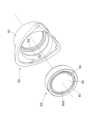
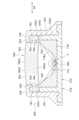
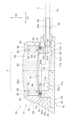
図1~図7は、第1の実施形態によるアクセスポート10を説明するための図である。このうち図1及び図2には、アクセスポート10の斜視図及び平面図が示されている。また、図3及び図4には、アクセスポート10の分解斜視図及び断面図が示されている。また、図5には、アクセスポート10の一部をなす基部材12の分解斜視図が示されている。また、図6には、アクセスポート10の隔膜体60及び蓋部材50の斜視図が示されている。また、図7には、アクセスポート10を用いて構成される医療システム90を示す回路図が示されている。Figures 1 to 7 are diagrams for explaining an
以下、図面を参照して本発明の第1の実施形態について説明する。The first embodiment of the present invention will now be described with reference to the drawings.
<アクセスポートの全体構成>
アクセスポート10は、カテーテルCと接続された状態で患者の皮下に埋設されて用いられる。図1乃至図4に示すように、アクセスポート10は、液体収容部11aを含むポート本体11と、ポート本体11に保持されて液体収容部11aを覆う隔膜体60と、を備える。隔膜体60に専用の穿刺針を刺して液体収容部11a内に薬剤を導入することで、カテーテルCを介して目的の病変部近傍に薬剤を届けることができる。<Overall configuration of the access port>
The
図4に示すように、ポート本体11は、液体収容部11aの内面(底面11b及び側面11c)を形成(区画)する基部材12と、基部材12に固定され基部材12との間で隔膜体60を保持する蓋部材50と、を有する。As shown in FIG. 4, the
図3及び図4に示すように、基部材12は、液体収容部11aの底面11bを形成(区画)する底壁部20と、底壁部20から延び出し液体収容部11aの側面11cを形成(区画)する側壁部30と、を有する。底壁部20は全体として平板な板状に形成されている。側壁部30は、筒状に形成されており、底壁部20の一側面の略中央に立設されている。3 and 4, the
図4に示すように、基部材12は、さらに、液体収容部11aに接続し液体収容部11aをカテーテルCの内部(内腔)Caに連通させる接続通路40を含む。図示された例では、接続通路40は、基部材12の上記側面11cに開口している。より具体的には、接続通路40の内面40aは、側壁部30に形成された接続通路開口41と、接続通路開口41に接続された接続ポート42とによって形成(区画)されている。接続通路開口41は、環状の側壁部30の内側から外側に向かう方向に沿って延びる貫通孔であり、側壁部30の内面30a及び外面30bに開口している。接続ポート42は、その一端が、側壁部30の外面30bの側から接続通路開口41に挿入されて、側壁部30に対して固定されている。接続ポート42の他端には、カテーテルCの一端が接続される。なお、接続通路40は、接続ポート42を含まなくてもよい。その場合、カテーテルCの一端は、接続通路開口41に挿入されてもよい。4, the
蓋部材50は、基部材12の側壁部30を外面30bの側から覆う環状の蓋本体部51を含む。蓋本体部51は、また、側壁部30の外側において、底壁部20を、側壁部30が立設された側から覆う。The
蓋部材50は、更に、側壁部30の底壁部20とは反対側となる端面(以下、「側壁部一側端面」とも称する)30cに対向して配置される環状の蓋環状縁部52を有する。蓋環状縁部52は、蓋本体部51の底壁部20とは反対側となる端部から、環状の蓋本体部51の内側へ向けて、側壁部一側端面30cに沿って延び出す。The
図3、図4及び図6に示すように、隔膜体60は、全体として平板な板状に形成されている。隔膜体60は、シリコーンゴム等により構成されている。隔膜体60は、側壁部一側端面30c上に、液体収容部11aを覆うように配置される。隔膜体60は、液体収容部11aとは反対側となる面(以下、「隔膜体一側面」とも称する)60aと、液体収容部11aの側となる面(以下、「隔膜体他側面」とも称する)60bとを有する。As shown in Figures 3, 4 and 6, the
図4に示すように、隔膜体60の外縁部61は、側壁部一側端面30cと蓋環状縁部52との間に圧縮された状態で保持され、基部材12と蓋部材50との間を液密にシールする。隔膜体60の中央部62は、液体収容部11aに対面して配置される。蓋環状縁部52が環状に形成されていることにより、上記中央部62が露出し、上記中央部62に穿刺針を刺すことができる。As shown in Figure 4, the
ところで、患者の体内に留置されたカテーテル内に更に径の小さいマイクロカテーテルを通し、マイクロカテーテルの先端を末梢血管領域まで進めて、目的の病変部のさらに近傍から薬剤の投与等を行うことが望まれている。この場合、マイクロカテーテルをカテーテル内に通す方法としては、まず、穿刺針を用いてアクセスポートの隔膜体を穿刺し、穿刺針の内腔、アクセスポートの内腔(液体収容部)及び接続通路を通じて、マイクロカテーテルをカテーテルの内腔に挿入することが考えられる。あるいは、まず、マイクロカテーテルよりも細くて腰の強いガイドワイヤを、上記穿刺針の内腔、アクセスポートの内腔(液体収容部)及び接続通路を通じてカテーテルの内腔に挿入し、ガイドワイヤをガイドにしてマイクロカテーテルをカテーテルの内腔に挿入することが考えられる。However, it is desirable to pass a microcatheter with a smaller diameter through the catheter placed in the patient's body, advance the tip of the microcatheter to the peripheral blood vessel region, and administer a drug from even closer to the target lesion. In this case, a method of passing a microcatheter through the catheter can be considered to first puncture the diaphragm of the access port with a puncture needle, and then insert the microcatheter into the catheter's lumen through the lumen of the puncture needle, the lumen (liquid-containing portion) of the access port, and the connecting passage. Alternatively, a guidewire that is thinner and stronger than the microcatheter can be first inserted into the catheter's lumen through the lumen of the puncture needle, the lumen (liquid-containing portion) of the access port, and the connecting passage, and then insert the microcatheter into the catheter's lumen using the guidewire as a guide.
マイクロカテーテルやガイドワイヤをカテーテルの内腔に挿入する際は、アクセスポート及びカテーテルは患者の皮下に埋設されている。このため、マイクロカテーテルやガイドワイヤの先端も接続通路も、直接観察することができない。したがって、マイクロカテーテルやガイドワイヤを操作してその先端を回転させながら、接続通路の位置を探る。When inserting a microcatheter or guidewire into the catheter lumen, the access port and catheter are buried under the patient's skin. For this reason, it is not possible to directly observe the tip of the microcatheter or guidewire or the connecting passage. Therefore, the location of the connecting passage is sought by manipulating the microcatheter or guidewire and rotating its tip.
しかしながら、このような方法では、マイクロカテーテルやガイドワイヤを安定して且つ容易に接続通路へ挿入することができない。However, this method does not allow for stable and easy insertion of a microcatheter or guidewire into the connecting passage.
このような事情を考慮して、本実施の形態のアクセスポートは、マイクロカテーテルやガイドワイヤを安定して且つ容易に接続通路へ挿入可能とするための工夫がなされている。Taking these circumstances into consideration, the access port of this embodiment has been designed to enable a microcatheter or guidewire to be inserted stably and easily into the connecting passage.
<傾斜領域>
具体的には、次のような工夫がなされている。すなわち、アクセスポート10は、接続通路40が液体収容部11aへ接続する接続位置Pでの接続通路40の軸方向D1に沿った断面において(図4参照)、隔膜体一側面60aと液体収容部11aの内面との間の上記軸方向D1に垂直な方向D2への長さLが、上記接続位置Pから離間するにつれてしだいに小さくなっていく傾斜領域Sを有する。言い換えると、傾斜領域S内では、上記軸方向D1に沿った断面における上記垂直な方向D2での隔膜体一側面60aと液体収容部の内面との距離Lは、上記接続位置Pに接近するにつれてしだいに大きくなっていく。<Tilted area>
Specifically, the following innovation has been implemented: That is, in a cross section (see FIG. 4 ) taken along the axial direction D1 of the connecting
このような傾斜領域Sにおいては、隔膜体一側面60aに対して垂直な方向に沿って液体収容部11aに挿入されたマイクロカテーテルやガイドワイヤの先端は、上記接続位置Pに近づく方向へ(したがって接続通路40に近づく方向へ)案内されやすくなる。In such an inclined region S, the tip of a microcatheter or guidewire inserted into the
また、傾斜領域Sは、上記軸方向D1に沿って液体収容部11aの半分を超える領域に形成されている。これにより、液体収容部11aに挿入されたマイクロカテーテルやガイドワイヤの先端が液体収容部11aの中心から外れた位置に到達した場合であっても、マイクロカテーテルやガイドワイヤの先端は、接続通路40に近づく方向へ案内されやすくなる。In addition, the inclined region S is formed in an area that exceeds half of the
以上により、マイクロカテーテルやガイドワイヤを安定して且つ容易に接続通路40へ挿入することができる。As a result, the microcatheter and guidewire can be inserted stably and easily into the connecting
さらに、図示された例では、傾斜領域Sは、上記接続位置Pから離間する側となる液体収容部11aの半分の領域を含んでいる。これにより、液体収容部11aに挿入されたマイクロカテーテルやガイドワイヤの先端が液体収容部11aの中心よりも上記接続位置Pから離れた位置に到達しても、当該先端は、接続通路40に近づく方向へ案内されやすくなる。Furthermore, in the illustrated example, the inclined region S includes half of the area of the
図示された例では、上記軸方向D1に沿った上記断面において(図4参照)、隔膜体一側面60aは、全体として上記軸方向D1に沿って広がっている。これに対し、上記軸方向D1に沿った上記断面において(図4参照)、傾斜領域Sにおける液体収容部11aの内面(ここでは底面11b)は、上記軸方向D1に対して傾斜している。より具体的には、傾斜領域Sにおける液体収容部11aの内面(底面11b)は、上記軸方向D1において上記接続位置Pに接近するにつれて隔膜体60から離間する側へ向かうように、上記軸方向D1に対して傾斜している。In the illustrated example, in the cross section along the axial direction D1 (see FIG. 4), one
より詳しくは、図5に示すように、液体収容部11aの底面11bは、接続通路40が開口した側壁面30dに接続した接続底面11dと、上記軸方向D1において接続底面11dに対して上記接続位置Pから離間する側に位置する主底面11eと、を含む。主底面11eは、接続底面11dに接続している。そして、主底面11eは、上記接続位置Pに接近するにつれて隔膜体60から離間する側へ向かうように上記軸方向D1に対して傾斜している。このような主底面11eにより、上記傾斜領域Sが形成されている。5, the
図示された例では、図4に示すように、主底面11eの領域における底壁部20の厚みTが、上記軸方向D1に沿って上記接続位置Pに接近するにつれてしだいに薄くなっている。これにより、主底面11eは、上記接続位置Pに接近するにつれて隔膜体60から離間する側へ向かうように上記軸方向D1に対して傾斜している。In the illustrated example, as shown in Fig. 4, the thickness T of the
<接続底面>
本実施の形態のアクセスポート10は、マイクロカテーテルやガイドワイヤを、さらに安定して且つ容易に接続通路40へ挿入可能とするための、さらなる工夫がなされている。具体的には、次のような工夫がなされている。<Connection bottom>
The
すなわち、図4に示すように、接続底面11dは、接続位置Pに接近するにつれて隔膜体60に接近する側へ向かうように上記軸方向D1に対して傾斜している。接続底面11dは、上記軸方向D1において主底面11eに対して上記接続位置Pに接近する側に位置する。このような接続底面11dにより、主底面11eによって上記接続位置Pへ向けて案内されたマイクロカテーテルやガイドワイヤの先端を、上記接続位置Pにさらに接近するにつれて隔膜体60に接近する方向に(すなわち側壁部30に形成された接続通路開口41に向けて)案内することができる。これにより、マイクロカテーテルやガイドワイヤを、さらに安定して且つ容易に接続通路40へ挿入可能とすることができる。That is, as shown in FIG. 4, the
<対向誘導面>
また、本実施の形態のアクセスポート10は、マイクロカテーテルやガイドワイヤを安定して且つ容易に接続通路40へ挿入可能とするための、さらなる工夫がなされている。具体的には、次のような工夫がなされている。<Opposite guide surface>
Furthermore, the
すなわち、図3に示すように、側壁部30は、底壁部20から離間して設けられた突出部31を含む。突出部31は、底面11bと対面する対向誘導面31aを有する。そして、突出部31は、対向誘導面31aと底面11bとの間となる位置に接続通路開口41が開口するように、配置されている。このような突出部31の対向誘導面31aと底面11bの対向誘導面31aに対面する領域とにより、マイクロカテーテルやガイドワイヤの先端を、接続通路開口41へ効率良く向けることができる。具体的には、上記先端の可動領域が対向誘導面31aと底面11bとの間に制限され、上記先端が対向誘導面31aと底面11bとの間となる位置に開口する接続通路開口41へ向けられやすくなる。That is, as shown in FIG. 3, the
とりわけ、図示された例では、図4に示すように、対向誘導面31aは、接続底面11dに対面する位置に配置されている。上述したように、接続底面11dは、接続通路開口41に接近するにつれて、隔膜体60に接近する側へ向かうように(したがって、対向誘導面31aに接近する側へ向かうように)、上記軸方向D1に対して傾斜している。対向誘導面31aがこのような接続底面11dと対面して設けられていることにより、マイクロカテーテルやガイドワイヤの先端の可動領域が接続通路開口41に接近するにつれて狭まり、対向誘導面31aと接続底面11dとの間となる位置に開口する接続通路開口41へ向けられやすくなる。In particular, in the illustrated example, as shown in Fig. 4, the opposing
さらに、図示された例では、図3に示すように、対向誘導面31aは、対向誘導面31aが底面11bと対面する方向と上記軸方向D1との両方に垂直な幅方向D3における中央部に、底面11bから離間するように凹んだ凹面31bを有している。このような凹面31bで囲まれた領域にマイクロカテーテルやガイドワイヤの先端が入り込むと、上記先端の可動範囲は、凹面31bで囲まれた領域内に制限される。したがって、上記軸方向D1と平行な方向からの観察において凹面31bによって囲まれる領域と接続通路開口41とが重なっている場合(図4参照)、上記先端がさらに接続通路開口41へ向けられやすくなる。Furthermore, in the illustrated example, as shown in Fig. 3, the opposing
図示された例では、図4に示すように、凹面31bは、接続通路40を形成(区画)する壁面40aに接続している。これにより、凹面31bに沿って接続通路開口41へ向けて移動するマイクロカテーテルやガイドワイヤの先端を、接続通路40内に向けることが容易である。すなわち、上記先端が、接続通路開口41が開口する側壁面30dと干渉して接続通路40内に進入することが妨げられる、という虞が低減される。In the illustrated example, as shown in Fig. 4, the
なお、図示された例では、図5に示すように、基部材12は、底面11bと側面11cの一部とを形成する底部材13と、底部材13に支持されて液体収容部11aを取り囲む環状の環状部材14と、を有する。環状部材14は、側面11cの他の一部を形成する。そして、上記突出部31は、環状部材14の上記接続位置Pに対応する位置に、液体収容部11a側へと突出して設けられている。底部材13と別体として作製された環状部材14に突出部31を形成することにより、側壁部30に上記突出部31を設けることが容易である。In the illustrated example, as shown in Fig. 5, the
さらに、環状部材14は、X線不透過材料で構成されている。これにより、アクセスポート10が患者の皮下に埋設された状態であっても、X線撮像技術を使用することにより、環状部材14で囲まれた領域(すなわち、マイクロカテーテルやガイドワイヤを液体収容部11aに挿入するための穿刺針を刺すべき領域)を把握することができる。Furthermore, the
<平坦壁部>
また、本実施の形態のアクセスポート10は、マイクロカテーテルやガイドワイヤを安定して且つ容易に接続通路へ挿入可能とするための、さらなる工夫がなされている。具体的には、次のような工夫がなされている。<Flat wall section>
Furthermore, the
すなわち、図5に示すように、側壁部30は、周方向に並べて設けられた一対の平坦壁部32,32を含む。一対の平坦壁部32,32は、接続通路開口41が当該一対の平坦壁部32,32の間となる位置において液体収容部11aの側面11cに開口するように、配置されている。また、一対の平坦壁部32,32は、底壁部20から側壁部30が延び出す方向(図示された例ではD2方向)と平行な方向からの観察において、直線状に延び且つ接続通路開口41に向けて先細りするテーパ状側面を形成している。このような一対の平坦壁部32,32により、マイクロカテーテルやガイドワイヤの先端を、接続通路40へ効率良く向けることができる。具体的には、一対の平坦壁部32,32によって、接続通路開口41に向けて案内されるだけでなく、上記先端の可動領域が接続通路開口41に接近するにつれて狭まる。That is, as shown in FIG. 5, the
<誘導リブ>
また、本実施の形態のアクセスポート10は、マイクロカテーテルやガイドワイヤを安定して且つ容易に接続通路40へ挿入可能とするための、さらなる工夫がなされている。具体的には、次のような工夫がなされている。<Guiding rib>
Furthermore, the
すなわち、図5に示すように、底壁部20は、底壁部20から側壁部30が延び出す方向と平行な方向(図示された例ではD2方向)からの観察において、接続位置Pに向けて線状に延びる誘導リブ21を有している。図示された例では、3本の誘導リブ21が、接続位置P近傍から放射状に延びている。このような誘導リブ21によって、液体収容部11a内に挿入されたマイクロカテーテルやガイドワイヤの先端を、接続位置Pへ向けて(したがって、接続通路開口41へ向けて)効率良く案内することができる。That is, as shown in Figure 5, the
<環状保持溝及び環状保持突起部>
さらに、本実施の形態のアクセスポート10は、隔膜体60がポート本体11から脱落することを防止するための工夫がなされている。具体的には、次のような工夫がなされている。<Annular Retaining Groove and Annular Retaining Protrusion>
Furthermore,
まず、図3及び図4に示すように、隔膜体60の隔膜体一側面60aには、環状の第1環状保持溝63が形成されている。第1環状保持溝63は、隔膜体60の外縁部61に形成されている。第1環状保持溝63は、底壁部20から側壁部30が延び出す方向と平行な方向(図示された例ではD2方向)に延びて液体収容部11aとは反対側に開口している。また、図4及び図6に示すように、ポート本体11の蓋部材50には、環状の第1環状保持突起部53が形成されている。第1環状保持突起部53は、蓋環状縁部52から、底壁部20から側壁部30が延び出す方向と平行な方向に突出している。そして、図4に示すように、第1環状保持突起部53は、第1環状保持溝63内に延び入っている。これにより、隔膜体60に穿刺針を刺す際や隔膜体60から穿刺針を引き抜く際等に隔膜体60に加わる力によって隔膜体60がポート本体11から脱落する、という虞が低減される。3 and 4, a first annular retaining
また、図4及び図6に示すように、隔膜体60の隔膜体他側面60bには、環状の第2環状保持溝64が形成されている。第2環状保持溝64は、隔膜体60の外縁部61に形成されている。第2環状保持溝64は、底壁部20から側壁部30が延び出す方向と平行な方向に延びて液体収容部11aの側に開口している。また、図3及び図4に示すように、ポート本体11の基部材12には、環状の第2環状保持突起部54が形成されている。第2環状保持突起部54は、側壁部一側端面30cから、底壁部20から側壁部30が延び出す方向と平行な方向に突出している。そして、図4に示すように、第2環状保持突起部54は、第2環状保持溝64内に延び入っている。このことによっても、隔膜体60に穿刺針を刺す際や隔膜体60から穿刺針を引き抜く際等に隔膜体60に加わる力によって隔膜体60がポート本体11から脱落する、という虞が低減される。4 and 6, a second
なお、上述したように、図示された例では、基部材12は、底部材13と、底部材13とは別体として形成された環状部材14とを有する。そして、図5に示すように、第2環状保持突起部54は、環状部材14に形成されている。このように、第2環状保持突起部54を底部材13とは別体の環状部材14に形成することにより、底部材13の形状に影響を与えることなく第2環状保持突起部54の形状や寸法を任意に変更することができる。As described above, in the illustrated example, the
<金属コイル及び発光体>
また、本実施の形態のアクセスポート10は、皮下に埋設されたアクセスポート10の位置を検出可能とするための工夫がなされている。具体的には、次のような工夫がなされている。<Metal coil and light emitter>
Furthermore, the
すなわち、図4に示すように、ポート本体11は、内蔵された金属コイル70を有する。金属コイル70には、発光体71が電気的に接続されている。図7に示す例では、金属コイル70は、発光体71、コンデンサ72及び抵抗73と共に並列回路74を構成している。そして、金属コイル70に磁場が印加されて回路74に電流が流れると、発光体71が発光するようになっている。That is, as shown in Fig. 4, the
このような金属コイル70及び発光体71がアクセスポート10に設けられていることにより、アクセスポート10近傍に磁場を印加して金属コイル70に電流が流れると、発光体71が発光する。そして、発光体71が発光する光によって、患者の皮下に埋設されたアクセスポート10の位置を把握することができる。言い換えると、このようなアクセスポート10によれば、図7に示すように、磁場を発生させる磁場発生装置80と共に、皮下に埋設されたアクセスポート10の位置を検出可能な医療システム90を構築することができる。By providing such a
また、アクセスポート10が金属コイル70を含むので、X線撮像技術を使用することによっても、患者の皮下に埋設されたアクセスポート10の位置を把握することができる。In addition, because the
なお、図示された例では、金属コイル70及び発光体71は、蓋部材50に埋設されている。これにより、発光体71の発する光がアクセスポート10の外に届きやすくなる。また、図示された例では、金属コイル70及び発光体71は、その全体が蓋部材50内に埋め込まれており、蓋部材50の表面に露出する部分がない。これにより、金属コイル70及び発光体71が、アクセスポート10が埋設された患者の体液や液体収容部11aに収容された薬剤等と接触する、ということが防止される。ここで、図示された例では、蓋部材50は透光性を有している。これにより、蓋部材50内の発光体71が発する光を、蓋部材50(アクセスポート10)の外に届けることができる。なお、発光体71の発光面71sは、蓋部材50(アクセスポート10)の外表面に可能な限り接近して配置されることが好ましい。発光面71sが上記外表面に接近しているほど、発光体71の発する光がアクセスポート10の外に届きやすくなる。したがって、アクセスポート10が患者の皮下に埋設された状態で、発光体71の発する光を患者の皮膚表面まで届けることが容易になる。すなわち、発光体71の発する光が、患者の周囲の者によって視認され易くなる。In the illustrated example, the
また、図示された例では、ポート本体11は、2つの金属コイル70a,70bと、各金属コイル70a,70bとそれぞれ電気的に接続した少なくとも2つの発光体71a,71bと、を有する。一方の金属コイル70a及び当該金属コイル70aに電気的に接続した発光体71aと、他方の金属コイル70b及び当該金属コイル70bに接続した発光体71bとは、液体収容部11aの周囲となる位置に互いから離間して設けられている。そして、隔膜体一側面60aは、金属コイル70a,70b及び発光体71a,71bの二つの組の間となる領域に露出している。したがって、アクセスポート10が患者の皮下に埋設された状態であっても、アクセスポート10の近傍に磁場を印加して発光体71a,71bを発光させれば、露出した隔膜体一側面60aの位置を(すなわちマイクロカテーテルやガイドワイヤを液体収容部11aに挿入するための穿刺針を刺すべき領域を)把握することができる。In the illustrated example, the
図示された例では、各金属コイル70の軸線70xは、側壁部30が底壁部20から延び上がる方向(図示された例ではD2方向)と平行な方向に延びている。図4から理解されるように、ポート本体11を構成する基部材12や蓋部材50は、側壁部30や蓋本体部51など、側壁部30が底壁部20から延び上がる方向に沿って延びる部分を有している。したがって、軸線70xの延びる方向を、側壁部30が底壁部20から延び上がる方向に沿わせれば、ポート本体11に金属コイル70を内蔵させることによるポート本体11の寸法の増大を、抑制することができる。さらに、図示された例では、発光体71は、各金属コイル70の軸線70x上に配置されている。このように発光体71を配置すれば、金属コイル70及び発光体71をポート本体11に内蔵させることによるポート本体11の寸法の増大を、抑制することができる。また、側壁部30が底壁部20から延び上がる方向からの観察において、発光体71を、隔膜体60の近傍に配置することができる。この結果、隔膜体60の位置をより正確に把握することができるようになる。In the illustrated example, the
図示された例では、金属コイル70及び発光体71を含む回路74は、蓋部材50の蓋本体部51に設けられた収容室55内に配置されている。コンデンサ72や抵抗73は、金属コイル70によって囲まれる空間内に配置されている。これにより、回路74を収容室55内にコンパクトに収容することができる。In the illustrated example, a
なお、磁場発生装置80としては、任意の装置を採用可能である。例えば、磁場発生装置80は、図7に示すような金属コイル81と電源82とスイッチ83が電気的に直列に接続された回路84を含む装置であってよい。このような磁場発生装置80によれば、スイッチ83を閉じることにより、金属コイル81に磁場を発生させることができる。Any device can be used as the magnetic
次に、図8乃至図13を参照し、アクセスポートの第2の実施形態について説明する。Next, a second embodiment of the access port will be described with reference to Figures 8 to 13.
図8乃至図13は、第2の実施形態によるアクセスポート100を説明するための図である。このうち、図8及び図9には、アクセスポート100の斜視図及び平面図が示されている。また、図10には、アクセスポート100の分解斜視図が、図11及び図12には、アクセスポート100の断面図が示されている。また、図13には、アクセスポート100の隔膜体160及び蓋部材150の斜視図が示されている。Figures 8 to 13 are diagrams for explaining the
図8乃至図13に示す第2の実施形態においては、接続通路40の上記軸方向D1に沿った断面において(図11参照)、液体収容部11aの底面が上記軸方向D1と平行に延びている一方、隔膜体160の液体収容部11aとは反対側となる面(隔膜体一側面)160aが上記軸方向D1に対して傾斜している点、が異なる。また、アクセスポート100が液体収容部11aの内面と接続通路40とを形成する表層部材115を含む点、が異なる。しかし、他の構成は、図1乃至図7に示す第1の実施の形態と略同一である。図8乃至図13に示す第2の実施の形態において、図1乃至図7に示す第1の実施の形態と同一部分には同一符号を付して詳細な説明は省略する。8 to 13, in a cross section along the axial direction D1 of the connection passage 40 (see FIG. 11), the bottom surface of the
以下、図8乃至図13を参照して、第2の実施形態によるアクセスポート100についてより詳細に説明する。Below, the
<アクセスポートの全体構成>
図10乃至図12に示すように、アクセスポート100は、液体収容部11aを含むポート本体111と、ポート本体111に保持されて液体収容部11aを覆う隔膜体160と、を備える。<Overall configuration of the access port>
As shown in FIGS. 10 to 12, the
ポート本体111は、基部材112と、基部材112に支持され液体収容部11aの内面を形成(区画)する表層部材115と、基部材112に固定され基部材112及び表層部材115との間で隔膜体160を保持する蓋部材150と、を有する。The
図10に示すように、基部材112は、全体として平板状の底壁部120と、底壁部120から延び出した側壁部130と、を有する。側壁部130は、全体として筒状に形成されており、底壁部120の一側面の略中央に立設されている。側壁部130には、後述する表層部材115の接続ポート部117を挿通する貫通孔133が形成されている。貫通孔133は、環状の側壁部130の内側から外側に向かう方向に沿って延び、側壁部130の内面130a及び外面130bに開口している。10, the
側壁部130の上記軸方向D1において貫通孔133から離間する側では、その底壁部20とは反対側となる端面(側壁部一側端面)130cが、上記軸方向D1において貫通孔133から離間するにつれて底壁部120に接近する側へ向かうように、傾斜している。On the side of the
図10乃至図12に示すように、蓋部材150は、基部材112の側壁部130を外面130bの側から覆う環状の蓋本体部151を含む。蓋本体部151は、側壁部130の外側において、底壁部120を、側壁部130が立設された側から覆う。10 to 12, the
蓋部材150は、更に、側壁部一側端面130cに対向して配置される環状の蓋環状縁部152を有する。蓋環状縁部152は、蓋本体部151の底壁部120とは反対側となる端部から、環状の蓋本体部151の内側へ向けて、側壁部一側端面130cに沿って延び出す。The
隔膜体160は、全体として板状に形成されている。隔膜体160は、シリコーンゴム等により構成されている。隔膜体160は、側壁部一側端面130c上に、液体収容部11aを覆うように配置される。隔膜体160は、液体収容部11aとは反対側となる面(隔膜体一側面)160aと、液体収容部11aの側となる面(隔膜体他側面)160bとを有する。The
隔膜体160の外縁部161は、側壁部一側端面130cと蓋環状縁部152との間に圧縮された状態で保持され、基部材112と蓋部材150との間を液密にシールしている。隔膜体160の中央部162は、液体収容部11aに対面して配置される。蓋環状縁部152が環状に形成されていることにより、上記中央部162が露出し、上記中央部162に穿刺針を刺すことができる。The
図10に示すように、表層部材115は、底壁部120及び側壁部130の内面を覆い、液体収容部11aの内面を形成する表層部材本体部116と、表層部材本体部116に接続され接続通路40を形成する接続ポート部117と、を含む。接続ポート部117の一端は、表層部材本体部116に接続している。接続ポート部117は、表層部材本体部116の内面116a上の接続部位置Pにおいて、液体収容部11aに開口している。また、図11に示すように、接続ポート部117は、側壁部130に設けられた貫通孔133に挿通されている。接続ポート部117の他端は、側壁部130の外側に配置されている。接続ポート部117の他端には、カテーテルCの一端が接続される。10, the
なお、図示された例では、上記軸方向D1に沿った断面において(図11参照)、表層部材本体部116の内面116aは上記軸方向D1と平行に延びている。In the illustrated example, in a cross section along the axial direction D1 (see FIG. 11), the inner surface 116a of the surface layer member
<隔膜体>
本実施の形態のアクセスポート100も、マイクロカテーテルやガイドワイヤを安定して且つ容易に接続通路へ挿入可能とするための工夫がなされている。具体的には、次のような工夫がなされている。<Diaphragm body>
The
図9及び図11に示すように、隔膜体160は、接続通路40の上記軸方向D1に沿った断面に垂直な方向(図示された例では、後述する方向D4)に沿って延びる屈曲部165を有する。隔膜体160の中央部162において、隔膜体一側面160aは、上記軸方向D1において上記屈曲部165の一側に位置する第1面160cと、上記軸方向D1において上記屈曲部165の他側に位置し第1面160cに対して傾斜する第2面160dと、を有する。第1面160cは、上記軸方向D1において上記接続位置Pから離間する側に位置している。一方、第2面160dは、第1面160cに対して上記軸方向D1において上記接続位置Pに接近する側に位置している。9 and 11, the
第1面160cは、上記軸方向D1に対して傾斜している。第1面160cは、上記軸方向D1において上記接続位置Pに接近するにつれて液体収容部11aの内面から離間する側へ向かうように上記軸方向D1に対して傾斜している。The
上述したように、アクセスポート100の上記軸方向D1に沿った断面において(図11参照)、表層部材本体部116の内面116aは、上記軸方向D1と平行に延びている。一方で、上記軸方向D1に沿った断面において、隔膜体一側面160aの一部である第1面160cは、上記軸方向D1に対して傾斜している。このような上記内面116a及び第1面160cによって、アクセスポート100に傾斜領域Sが形成される。そして、このような傾斜領域Sにおいては、隔膜体一側面160aに対して垂直な方向に沿って液体収容部11aに挿入されたマイクロカテーテルやガイドワイヤの先端は、上記接続位置Pに近づく方向へ(したがって接続通路40に近づく方向へ)案内されやすい。As described above, in a cross section of the
図示された例では、第2面160dの上記軸方向D1に対する傾斜角度は、第1面160cの上記軸方向D1に対する傾斜角度よりも小さい。これにより、アクセスポート100が患者の皮下に埋設された状態であっても、第1面160cの位置を把握することができる。In the illustrated example, the inclination angle of the
また、上記軸方向D1に沿った第2面160dの長さLdは、上記軸方向D1に沿った第1面160cの長さLcよりも短い。これにより、第1面160cを(すなわち、マイクロカテーテルやガイドワイヤを液体収容部11aに挿入するための穿刺針を刺すべき領域を)広く確保することができる。In addition, the length Ld of the
<表層部材>
本実施の形態のアクセスポート100は、マイクロカテーテルやガイドワイヤを安定して且つ容易に接続通路へ挿入可能とするための、さらなる工夫がなされている。具体的には、次のような工夫がなされている。<Surface material>
The
すなわち、図11に示すように、表層部材本体部116の内面116a(液体収容部11aの内面)と接続ポート部117の内面(接続通路40を形成する壁面40a)とは、継ぎ目無しで接続されている。言い換えると、表層部材115は、液体収容部11aの内面と接続通路40との間を継ぎ目無しで接続している。これにより、マイクロカテーテルやガイドワイヤの先端が、表層部材本体部116の内面116aや接続ポート部117と干渉して接続通路40内に進入することが妨げられる、という虞が低減される。11, the inner surface 116a of the surface layer member main body 116 (the inner surface of the
また、表層部材本体部116の内面116aは、漏斗状となっている。そして、図12に示すように、接続通路40の上記軸方向D1に垂直な断面において、表層部材本体部116の内面116aは、隔膜体他側面160bに沿った方向D4における両外方において隔膜体160に接近するように隔膜体他側面160bに対して傾斜している。言い換えると、接続通路40の上記軸方向D1に垂直な上記断面において、表層部材本体部116の内面116aはU字状に延びている。このような表層部材本体部116の内面116aによって、マイクロカテーテルやガイドワイヤの先端の可動領域が、上記方向D4において狭められ、上記接続位置Pへ向けられやすくなる。The inner surface 116a of the surface layer member
なお、図示された例では、表層部材115は金属で構成されている。これにより、アクセスポート100が患者の皮下に埋設された状態であっても、X線撮像技術を使用することで、表層部材本体部116によって形成される液体収容部11aの位置(すなわち、マイクロカテーテルやガイドワイヤを液体収容部11aに挿入するための穿刺針を刺すべき領域を)及び、接続ポート部117の位置(すなわち接続位置P)を把握することができる。In the illustrated example, the
<環状保持溝及び環状保持突起部>
さらに、本実施の形態のアクセスポート100も、隔膜体160がポート本体111から脱落することを防止するための工夫がなされている。具体的には、次のような工夫がなされている。<Annular Retaining Groove and Annular Retaining Protrusion>
Furthermore,
まず、図10乃至図12に示すように、隔膜体160の隔膜体一側面160aには、環状の第1環状保持溝163が形成されている。第1環状保持溝163は、隔膜体160の外縁部161に形成されている。第1環状保持溝163は、基部材112の底壁部120から側壁部130が延び出す方向と平行な方向に延びて液体収容部11aとは反対側に開口している。また、図11乃至図13に示すように、ポート本体111の蓋部材150には、環状の第1環状保持突起部153が形成されている。第1環状保持突起部153は、蓋環状縁部152から、底壁部120から側壁部130が延び出す方向と平行な方向に突出している。そして、図11及び図12に示すように、第1環状保持突起部153は、第1環状保持溝163内に延び入っている。これにより、隔膜体160に穿刺針を刺す際や隔膜体160から穿刺針を引き抜く際等に隔膜体160に加わる力によって隔膜体160がポート本体111から脱落する、という虞が低減される。10 to 12, a first
また、図11乃至図13に示すように、隔膜体160の隔膜体他側面160bには、環状の第2環状保持溝164が形成されている。第2環状保持溝164は、隔膜体160の外縁部161に形成されている。第2環状保持溝164は、基部材112の底壁部120から側壁部130が延び出す方向と平行な方向に延びて液体収容部11aの側に開口している。また、図10乃至図12に示すように、表層部材本体部116の縁部は、底壁部120から側壁部130が延び出す方向と平行な方向に延びる第2環状保持突起部154をなしている。そして、図11及び図12に示すように、第2環状保持突起部154は、第2環状保持溝164内に延び入っている。このことによっても、隔膜体160に穿刺針を刺す際や隔膜体160から穿刺針を引き抜く際等に隔膜体160に加わる力によって隔膜体160がポート本体111から脱落する、という虞が低減される。Also, as shown in Figures 11 to 13, a second
以上、図1乃至図13を参照して、第1及び第2の実施形態によるアクセスポート10,100について説明してきたが、アクセスポート10,100の構成は上述したものに限られない。図1乃至図13に示すアクセスポートの構成には、種々の変更を施すことが可能である。Although the
例えば、第2の実施形態によるアクセスポート100において、隔膜体160は屈曲部165を有していなくてもよい。言い換えると、隔膜体一側面160aは、第1面160cに対して傾斜する第2面160dを有していなくてもよい。For example, in the
また、第1及び第2の実施形態によるアクセスポート10,100は、発光体71を含まなくてもよい。この場合、磁場発生装置80は、磁場発生装置80によって磁場を印加した際にアクセスポート10,100の金属コイル70による上記磁場の乱れを検出して報知する報知機能を有していればよい。このようにすれば、磁場発生装置80の報知機能によって、磁場発生装置80の近傍に金属コイル70が存在することを(したがって、アクセスポート10,100の隔膜体60,160が存在することを)、把握することができる。In addition, the
また、第1及び第2の実施形態によるアクセスポート10,100は、3以上の金属コイル70、又は、3組以上の金属コイル70及び発光体71を有していてもよい。液体収容部11aの周囲となる位置に、3以上の金属コイル70、又は、3組以上の金属コイル70及び発光体71が互いから離間して設けられていれば、液体収容部11aの位置(すなわちマイクロカテーテルやガイドワイヤを液体収容部11aに挿入するための穿刺針を刺すべき領域)を、より容易に把握することができる。Furthermore, the
また、第1及び第2の実施形態によるアクセスポート10,100は、図14に示すように、ただ1つの金属コイル70を有していてもよい。この場合、金属コイル70には、2以上の発光体71a,71bが電気的に接続され、発光体71a,71bは隔膜体60,160を取り囲むように配置されていることが好ましい。また、この場合、図14及び図15に示すように、底壁部20から側壁部30が延び出す方向と平行な方向からの観察において液体収容部11aを取り囲むように、金属コイル70を配置してもよい。The
また、金属コイル70は、ポート本体11のどの部分に内蔵されていてもよい。例えば、図16に示すように、金属コイル70は、基部材12に内蔵されていてもよい。この場合、金属コイル70は、側壁部30に内蔵されてもよい。この場合、図16に示すように、基部材12を底部材13と底部材13とは別体の環状部材14とで構成し、金属コイル70を環状部材14に内蔵させてもよい。このようにすれば、金属コイル70が上記患者の体液や液体収容部11aに収容される薬剤に接触することのないように、金属コイル70を基部材12に内蔵させることが容易である。The
また、発光体71の発光面71sは、アクセスポート10,100の表面(液体収容部11aの側を向く面とは反対側の面)に露出していてもよい。この場合、アクセスポート10,100が患者の皮下に埋設された状態で、発光体71の発する光を患者の皮膚表面まで届けることが容易である。すなわち、発光体71の発する光が、患者の周囲の者によって視認され易くなる。なお、発光体71の発光面71sがアクセスポート10,100の表面に露出している場合、金属コイル70及び発光体71を含む回路74を収容する空間のうち金属コイル70を含む金属部材を収容する部分は、液密にシールされていることが望ましい。これにより、上記金属部材と、アクセスポート10,100が埋設された患者の体液や液体収容部11aに収容された薬剤等と、の接触が防止される。The light-emitting
以上のように、第1及び第2の実施の形態によれば、アクセスポート10,100は、カテーテルCと接続して用いられるアクセスポートであって、液体収容部11aを含むポート本体11,111と、ポート本体11,111に保持されて液体収容部11aを覆う隔膜体60,160と、を備えている。ポート本体11,111は、液体収容部11aに接続し液体収容部11aをカテーテルCの内部に連通させる接続通路40を含む。そして、接続通路40が液体収容部11aへ接続する接続位置Pでの接続通路40の軸方向D1に沿った断面における、隔膜体60,160の液体収容部11aとは反対側となる面60a,160aと液体収容部11aの内面との間の上記軸方向D1に垂直な方向への長さLが、上記軸方向D1に沿って液体収容部11aの半分を超える傾斜領域S内にて、上記接続位置Pから離間するにつれてしだいに小さくなっていく。As described above, according to the first and second embodiments, the
このようなアクセスポート10,100によれば、傾斜領域Sにおいて、隔膜体一側面60a,160aに対して垂直な方向に沿って液体収容部11aに挿入されたマイクロカテーテルやガイドワイヤの先端は、上記接続位置Pに近づく方向へ(したがって接続通路40に近づく方向へ)案内されやすくなる。また、傾斜領域Sが上記軸方向D1に沿って液体収容部11aの半分を超える領域に形成されていることにより、液体収容部11aに挿入されたマイクロカテーテルやガイドワイヤの先端が液体収容部11aの中心から外れた位置に到達した場合であっても、マイクロカテーテルやガイドワイヤの先端は、接続通路40に近づく方向へ案内されやすくなる。以上により、マイクロカテーテルやガイドワイヤを安定して且つ容易に接続通路40へ挿入することができる。According to such an
また、第1及び第2の実施の形態によるアクセスポート10,100において、傾斜領域Sは、上記接続位置Pから離間する側となる液体収容部11aの半分の領域を含んでいる。これにより、液体収容部11aに挿入されたマイクロカテーテルやガイドワイヤの先端が液体収容部11aの中心よりも上記接続位置Pから離れた位置に到達しても、当該先端は、接続通路40に近づく方向へ案内されやすくなる。Furthermore, in the
第1の実施の形態によるアクセスポート10では、接続通路40の上記軸方向D1に沿った断面において、傾斜領域Sにおける液体収容部11aの内面が上記軸方向D1に対して傾斜している。このような液体収容部11aにより、傾斜領域Sが形成される。In the
また、第1の実施の形態によるアクセスポート10において、ポート本体11の内面は、液体収容部11aを形成(区画)する底面11b及び上記底面11bから延び出し液体収容部11aを形成(区画)する側面11cを含み、上記底面11bは上記軸方向D1に対して傾斜している。このような底面11bにより、傾斜領域Sが形成される。In the
また、第1の実施の形態によるアクセスポート10において、ポート本体11は、液体収容部11aの底面11bを形成する底壁部20を有している。そして、底壁部20の厚みTは、上記軸方向D1に沿って上記接続位置Pに接近するにつれてしだいに薄くなっている。これにより、上記底面11bは上記軸方向D1に対して傾斜している。In the
また、第1の実施の形態によるアクセスポート10において、ポート本体11の上記底面11bは、接続通路40が開口した側壁面30dに接続した接続底面11dと、上記軸方向D1において接続底面11dに対して上記接続位置Pから離間する側に位置する主底面11eと、を含む。そして、主底面11eは、上記接続位置Pに接近するにつれて隔膜体60から離間する側へ向かうように上記軸方向D1に対して傾斜している。このような主底面11eにより、傾斜領域Sが形成される。In the
また、第1の実施の形態によるアクセスポート10において、接続底面11dは、上記接続位置Pに接近するにつれて隔膜体60に接近する側へ向かうように上記軸方向D1に対して傾斜している。このような接続底面11dにより、主底面11eによって上記接続位置Pへ向けて案内されたマイクロカテーテルやガイドワイヤの先端を、上記接続位置Pにさらに接近するにつれて隔膜体60に接近する方向に(すなわち側壁部30に形成された接続通路40の開口41に向けて)案内することができる。これにより、マイクロカテーテルやガイドワイヤを、さらに安定して且つ容易に接続通路40へ挿入可能とすることができる。In the
また、第1の実施の形態によるアクセスポート10において、ポート本体11は、液体収容部11aの底面11bを形成する底壁部20と、液体収容部11aの側面11cを形成する側壁部30と、を有している。そして、側壁部30は、底壁部20から離間して設けられ且つ底面11bと対面する対向誘導面31aを有した突出部31を有している。また、接続通路40は、対向誘導面31aと上記底面11bとの間となる位置において上記側面11cに開口している。In the
このような突出部31の対向誘導面31aと底面11bの対向誘導面31aに対面する領域とにより、マイクロカテーテルやガイドワイヤの先端が、接続通路開口41へ効率良く向けられる。具体的には、上記先端の可動範囲が対向誘導面31aと底面11bとの間に制限され、上記先端が対向誘導面31aと底面11bとの間となる位置に開口する接続通路40の開口41へ向けられやすくなる。The opposing
また、第1の実施の形態によるアクセスポート10において、対向誘導面31aは、対向誘導面31aが上記底面11bと対面する方向と上記軸方向D1との両方に垂直な幅方向D3における中央部に、上記底面11bから離間するように凹んだ凹面31bを有している。このような凹面31bで囲まれた領域にマイクロカテーテルやガイドワイヤの先端が入り込むと、上記先端の可動範囲は、凹面31bで囲まれた領域内に制限される。したがって、上記先端がさらに接続通路40の開口41へ向けられやすくなる。In the
また、第1の実施の形態によるアクセスポート10において、上記凹面31bは、接続通路40を形成(区画)する壁面40aに接続している。これにより、凹面31bに沿って接続通路開口41へ向けて移動するマイクロカテーテルやガイドワイヤの先端を、接続通路40内へ向けることが容易である。すなわち、上記先端が、接続通路開口41が開口する側壁面30dと干渉して接続通路40内に進入することが妨げられる、という虞が低減される。In the
また、第1の実施の形態によるアクセスポート10において、ポート本体11の内面は、対向誘導面31aと対面する位置に設けられた接続底面11dと、上記軸方向D1において接続底面11dに対して上記接続位置Pから離間する側に位置する主底面11eと、を含む。そして、主底面11eは、上記接続位置Pに接近するにつれて隔膜体60から離間する側へ向かうように上記軸方向D1に対して傾斜している。また、接続底面11dは、上記接続位置Pに接近するにつれて隔膜体60に接近する側へ向かうように上記軸方向D1に対して傾斜している。対向誘導面31aがこのような接続底面11dと対面して設けられていることにより、マイクロカテーテルやガイドワイヤの先端の可動領域が上記接続位置Pに接近するにつれて狭まり、対向誘導面31aと底面11bとの間となる位置に開口する接続通路40へ向けられやすくなる。In the
また、第1の形態によるアクセスポート10において、ポート本体11は、液体収容部11aの底面11b及び側面11cを形成する基部材12と、基部材12に固定され基部材12との間で隔膜体60を保持する蓋部材50と、を有している。基部材12は、底面11bを少なくとも形成する底部材13と、底部材13に支持されて液体収容部11aを取り囲む環状の環状部材14と、を有している。そして、環状部材14は、上記接続位置Pに対応して設けられ液体収容部11a側へと突出した突出部31を有している。このように底部材13と別体として作製された環状部材14に突出部31を形成することにより、側壁部30に上記突出部31を設けることが容易である。In the
また、第1の形態によるアクセスポート10において、環状部材14は、X線不透過材料で構成されている。これにより、アクセスポート10が患者の皮下に埋設された状態であっても、X線撮像技術を使用することにより、環状部材14で囲まれた領域(すなわち、マイクロカテーテルやガイドワイヤを液体収容部11aに挿入するための穿刺針を刺すべき領域)を把握することができる。Furthermore, in the
また、第1の実施の形態によるアクセスポート10において、ポート本体11は、液体収容部11aの底面11bを形成する底壁部20と、底壁部20から延び出し液体収容部11aの側面11cを形成する側壁部30と、を有している。そして、側壁部30は、周方向に並べて設けられた一対の平坦壁部32,32を含む。また、接続通路40は、一対の平坦壁部32,32の間となる位置において上記側面11cに開口している。また、一対の平坦壁部32,32は、底壁部20から側壁部30が延び出す方向と平行な方向からの観察において、直線状に延び且つ接続通路40に向けて先細りするテーパ状側面を形成している。このような一対の平坦壁部32,32により、マイクロカテーテルやガイドワイヤの先端を、接続通路40へ効率良く向けることができる。具体的には、一対の平坦壁部32,32によって、上記先端の可動領域が接続通路40に接近するにつれて狭まり、且つ、接続通路40に向けて案内される。In the
また、第1の実施の形態によるアクセスポート10において、ポート本体11は、液体収容部11aの底面11bを形成する底壁部20と、底壁部20から延び出し液体収容部11aの側面11cを形成する側壁部30と、を有している。側壁部30は、周方向に並べられた一対の平坦壁部32,32を含み、接続通路40は、一対の平坦壁部32,32の間となる位置において上記側面11cに開口している。そして、底壁部20は、底壁部20から側壁部30が延び出す方向と平行な方向からの観察において、上記接続位置Pに向けて線状に延びる誘導リブ21を有している。このようなアクセスポート10によれば、誘導リブ21によって、液体収容部11a内に挿入されたマイクロカテーテルやガイドワイヤの先端を、接続位置Pへ向けて効率良く案内することができる。In the
また、第1の形態によるアクセスポート10において、ポート本体11は、液体収容部11aの底面11bを形成する底壁部20と、底壁部20から延び出し液体収容部11aの側面11cを形成する側壁部30と、を有している。そして、隔膜体60は、底壁部20から側壁部30が延び出す方向と平行な方向に延びて液体収容部11aとは反対側に開口した環状の環状保持溝63を形成されている。また、ポート本体11は、底壁部20から側壁部30が延び出す方向と平行な方向に突出した環状保持突起部53を有している。環状保持溝63に環状保持突起部53を嵌め込むことにより、隔膜体60に穿刺針を刺す際や隔膜体60から穿刺針を引き抜く際等に隔膜体60に加わる力によって隔膜体60がポート本体11から脱落する、という虞が低減される。In the
また、第2の形態によるアクセスポート100において、ポート本体111は、液体収容部11aの内面と接続通路40とを形成する表層部材115を有している。そして、表層部材115は、液体収容部11aの内面と接続通路40との間を継ぎ目無しで接続されている。これにより、マイクロカテーテルやガイドワイヤの先端が、液体収容部11aの内面や接続ポート部117と干渉して接続通路40内に進入することが妨げられる、という虞が低減される。In the second embodiment of the
また、第2の形態によるアクセスポート100において、表層部材115は、金属で構成されている。これにより、アクセスポート100が患者の皮下に埋設された状態であっても、X線撮像技術を使用すれば、表層部材115によって形成される液体収容部11aの位置を(すなわち、マイクロカテーテルやガイドワイヤを液体収容部11aに挿入するための穿刺針を刺すべき領域を)把握することができる。Furthermore, in the
また、第2の形態によるアクセスポート100では、接続通路40の上記軸方向D1に垂直な断面において、ポート本体111の内面は、隔膜体160の表層部材本体部116の内面に対向する面160bに沿った方向D4における両外方において隔膜体160に接近するように上記内面に対向する面に対して傾斜している。より具体的には、接続通路40の軸方向D1に垂直な断面において、ポート本体111の内面116aはU字状に延びている。このようなポート本体111の内面116aによって、マイクロカテーテルやガイドワイヤの先端の可動領域が狭まり、上記接続通路40へ向けられやすくなる。In the
また、第2の形態によるアクセスポート100において、接続通路40の上記軸方向D1に沿った断面において、隔膜体160の液体収容部11aとは反対側となる面160aは、上記軸方向D1に対して傾斜している。このような面160aによって、アクセスポート100に傾斜領域Sが形成される。そして、隔膜体160の上記反対側となる面160aに対して垂直な方向に沿って液体収容部11aに挿入されたマイクロカテーテルやガイドワイヤの先端は、上記接続通路40に近づく方向へ案内されやすくなる。In the
また、第2の形態によるアクセスポート100において、隔膜体160の液体収容部11aとは反対側となる面160aは、上記軸方向D1において上記接続位置Pから離間する側に位置する第1面160cと、第1面160cに対して上記軸方向D1において上記接続位置Pに接近する側に位置する第1面160cに対して傾斜した第2面160dと、を有する。そして、上記軸方向D1に沿った第1面160cの長さLcは、上記軸方向D1に沿った第2面160dの長さLdよりも長い。また、第1面160cは、上記軸方向D1において上記接続位置Pに接近するにつれて液体収容部11aの内面から離間する側へ向かうように上記軸方向D1に対して傾斜している。また、第1面160cの上記軸方向D1に対する傾斜角度は、第2面160dの上記軸方向D1に対する傾斜角度よりも大きい。In the
第1面160cの上記傾斜角度が第2面160dの上記傾斜角度よりも大きいことにより、アクセスポート100が患者の皮下に埋設された状態であっても、第1面160cの位置を把握することができる。また、第1面160cの上記長さLcが第2面160dの上記長さLdよりも長いことにより、第1面160cを(すなわち、マイクロカテーテルやガイドワイヤを液体収容部11aに挿入するための穿刺針を刺すべき領域を)広く確保することができる。Because the inclination angle of the
また、第1及び第2の実施の形態によるアクセスポート10,100において、ポート本体11,111は、内蔵された金属コイル70を有している。これにより、患者の皮下に埋設されたアクセスポート10,100の位置を、磁場発生装置80又はX線撮像技術を使用して把握することができる。In addition, in the
また、第1及び第2の実施の形態によるアクセスポート10,100において、ポート本体11,111は、液体収容部11aの周囲となる位置に互いから離間して設けられた少なくとも二つの金属コイル70a,70bを有している。これにより、患者の皮下に埋設されたアクセスポート10,100の位置を、磁場発生装置80又はX線撮像技術を使用して、より正確に把握することができる。In the
また、第1及び第2の実施の形態によるアクセスポート10,100において、隔膜体60,160の液体収容部11aとは反対側となる面60a,160aは、上記二つの金属コイル70a,70bの間となる領域に露出している。これにより、患者の皮下に埋設されたアクセスポート10,100の隔膜体60,160の位置を(すなわちマイクロカテーテルやガイドワイヤを液体収容部11aに挿入するための穿刺針を刺すべき領域を)、磁場発生装置80又はX線撮像技術を使用して、より正確に把握することができる。In the
また、第1及び第2の実施の形態によるアクセスポート10,100において、ポート本体11,111は、各金属コイル70a,70bとそれぞれ電気的に接続した少なくとも二つの発光体71a,71bを有している。これにより、アクセスポート10,100の近傍に磁場を印加すると、金属コイル70a,70bと発光体71a,71bとを含む回路74に電流が流れ、発光体71a,71bが発光する。そして、発光体71a,71bが発光する光によって、患者の皮下に埋設されたアクセスポート10,100の位置を把握することができる。In the
また、変形例によるアクセスポート10,100において、上記少なくとも二つの発光体71a,71bの発光面71sは露出している。これにより、アクセスポート10が患者の皮下に埋設された状態で、発光体71の発する光を患者の皮膚表面まで届けることが容易である。すなわち、発光体71の発する光が、患者の周囲の者によって視認され易くなる。In addition, in the
また、変形例によるアクセスポート10において、ポート本体11は、液体収容部11aの底面11bを形成する底壁部20と、液体収容部11aの側面11cを形成する側壁部30と、を有している。そして、上記少なくとも二つの金属コイル70a,70bは、側壁部30に内蔵されている。これにより、液体収容部11aの位置を、より正確に把握することができる。In the
また、第1及び第2の実施の形態によるアクセスポート10,100において、各金属コイル70a,70bの軸線70xは、側壁部30,130が底壁部20,120から延び上がる方向と平行な方向に延びている。ここで、ポート本体11,111を構成する基部材12、112や蓋部材50,150は、側壁部30が底壁部20から延び上がる方向に沿って延びる部分を有している。したがって、軸線70xの延びる方向を、側壁部30,130が底壁部20,120から延び上がる方向に沿わせれば、ポート本体11,111に金属コイル70を内蔵させることによるポート本体11,111の寸法の増大を、抑制することができる。In the
以上において、複数の実施の形態とその変形例を説明してきたが、当然に、異なる実施形態や異なる変形例として説明された複数の構成を適宜組み合わせることも可能である。Although several embodiments and their variations have been described above, it is of course possible to combine multiple configurations described as different embodiments or variations as appropriate.
10及び100・・・アクセスポート、11及び111・・・ポート本体、11a・・・液体収容部、11b・・・底面、11c・・・側面、11d・・・接続底面、11e・・・主底面、12・・・基部材、13・・・底部材、14・・・環状部材、20・・・底壁部、21・・・誘導リブ、30・・・側壁部、31・・・突出部、31a・・・対向誘導面、31b・・・凹面、32・・・平坦壁部、40・・・接続通路、40a・・・壁面、50及び150・・・蓋部材、60及び160・・・隔膜体、70,70a及び70b・・・金属コイル、71,71a及び71b・・・発光体、115・・・表層部材、160c・・・第1面、160d・・・第2面10 and 100: access port, 11 and 111: port body, 11a: liquid storage section, 11b: bottom surface, 11c: side surface, 11d: connection bottom surface, 11e: main bottom surface, 12: base member, 13: bottom member, 14: annular member, 20: bottom wall portion, 21: guide rib, 30: side wall portion, 31: protrusion, 31a: opposing guide surface, 31b: concave surface, 32: flat wall portion, 40: connection passage, 40a: wall surface, 50 and 150: cover member, 60 and 160: diaphragm body, 70, 70a and 70b: metal coil, 71, 71a and 71b: light emitting body, 115: surface member, 160c: first surface, 160d: second surface
Claims (10)
Translated fromJapanese液体収容部を含むポート本体と、
前記ポート本体に保持されて前記液体収容部を覆う隔膜体と、を備え、
前記ポート本体は、前記液体収容部に接続し前記液体収容部を前記カテーテルの内部に連通させる接続通路を含み、
前記接続通路が前記液体収容部へ接続する接続位置での前記接続通路の軸方向に沿った断面における、前記隔膜体の前記液体収容部とは反対側となる面と前記液体収容部の内面との間の前記軸方向に垂直な方向への長さが、前記軸方向に沿って前記液体収容部の半分を超える傾斜領域内にて、前記接続位置から離間するにつれてしだいに小さくなっていき、
前記隔膜体の前記液体収容部とは反対側となる面は、前記軸方向において前記接続位置から離間する側に位置する第1面と、該第1面に対して前記軸方向において前記接続位置に接近する側に位置する前記第1面に対して傾斜した第2面と、を有し、
前記軸方向に沿った前記第1面の長さは前記軸方向に沿った前記第2面の長さよりも長く、
前記第1面は、前記軸方向において前記接続位置に接近するにつれて前記液体収容部の内面から離間する側へ向かうように前記軸方向に対して傾斜し、
前記第1面の前記軸方向に対する傾斜角度は、前記第2面の前記軸方向に対する傾斜角度よりも大きい、アクセスポート。 An access port for use in connection with a catheter,
a port body including a liquid storage portion;
a diaphragm body held by the port body and covering the liquid storage portion,
the port body includes a connection passage that is connected to the liquid containing portion and communicates the liquid containing portion with the inside of the catheter;
a length in a direction perpendicular to the axial direction between a surface of the diaphragm opposite the liquid storage portion and an inner surface of the liquid storage portion at a connection position where the connection passage is connected to the liquid storage portion graduallydecreases with distance from the connection position within an inclined region that exceeds half of the liquid storage portion along the axial direction,
a surface of the diaphragm body opposite to the liquid storage portion has a first surface located away from the connection position in the axial direction, and a second surface inclined with respect to the first surface located closer to the connection position in the axial direction,
a length of the first surface along the axial direction is greater than a length of the second surface along the axial direction;
the first surface is inclined with respect to the axial direction so as to move away from the inner surface of the liquid storage portion as the first surface approaches the connection position in the axial direction;
An access port, wherein an inclination angle of the first surface relative to the axial direction is greater than an inclination angle of the second surface relative to the axial direction .
前記側壁部は、前記底壁部から離間して設けられ且つ前記底面と対面する対向誘導面を有した突出部を有し、
前記接続通路は、前記対向誘導面と前記底面との間となる位置において前記側面に開口している、請求項1記載のアクセスポート。 the port body has a bottom wall portion that forms a bottom surface of the liquid storage portion, and a side wall portion that forms a side surface of the liquid storage portion,
the side wall portion has a protruding portion provided at a distance from the bottom wall portion and having an opposing guide surface facing the bottom surface,
The access port according to claim 1 , wherein the connecting passage opens into the side surface at a position between the opposing guide surface and the bottom surface.
前記側壁部は、周方向に並べられた一対の平坦壁部を含み、
前記接続通路は、前記一対の平坦壁部の間となる位置において前記側面に開口し、
前記底壁部は、該底壁部から前記側壁部が延び出す方向と平行な方向からの観察において、前記接続位置に向けて線状に延びる誘導リブを有する、請求項1~3のいずれか一項記載のアクセスポート。 the port body has a bottom wall portion that forms a bottom surface of the liquid storage portion, and a side wall portion that extends from the bottom wall portion and forms a side surface of the liquid storage portion,
The side wall portion includes a pair of flat wall portions aligned in the circumferential direction,
the connecting passage opens to the side surface at a position between the pair of flat wall portions,
An access port according to any one of claims 1 to 3, wherein the bottom wall portion has a guide rib extending linearly toward the connection position when observed from a direction parallel to the direction in which the side wall portion extends from the bottom wall portion.
前記表層部材は、前記液体収容部の内面と前記接続通路との間を継ぎ目無しで接続されている、請求項1~4のいずれか一項記載のアクセスポート。 the port body has a surface member that forms an inner surface of the liquid storage portion and the connecting passage,
5. The access port according to claim 1, wherein the surface member seamlessly connects the inner surface of the liquid storage portion and the connecting passage.
前記少なくとも二つの金属コイルは、前記側壁部に内蔵されている、請求項9記載のアクセスポート。 the port body has a bottom wall portion that forms a bottom surface of the liquid storage portion, and a side wall portion that forms a side surface of the liquid storage portion,
The access port of claim9 , wherein the at least two metal coils are embedded within the side wall.
Applications Claiming Priority (3)
| Application Number | Priority Date | Filing Date | Title |
|---|---|---|---|
| JP2020024533 | 2020-02-17 | ||
| JP2020024533 | 2020-02-17 | ||
| PCT/JP2021/003854WO2021166643A1 (en) | 2020-02-17 | 2021-02-03 | Access port |
Publications (2)
| Publication Number | Publication Date |
|---|---|
| JPWO2021166643A1 JPWO2021166643A1 (en) | 2021-08-26 |
| JP7582180B2true JP7582180B2 (en) | 2024-11-13 |
Family
ID=77390789
Family Applications (1)
| Application Number | Title | Priority Date | Filing Date |
|---|---|---|---|
| JP2021506595AActiveJP7582180B2 (en) | 2020-02-17 | 2021-02-03 | Access Port |
Country Status (8)
| Country | Link |
|---|---|
| US (1) | US20230025137A1 (en) |
| EP (1) | EP4108269A4 (en) |
| JP (1) | JP7582180B2 (en) |
| KR (1) | KR20220142426A (en) |
| CN (1) | CN115103705B (en) |
| PH (1) | PH12022551485A1 (en) |
| TW (1) | TWI841822B (en) |
| WO (1) | WO2021166643A1 (en) |
Citations (5)
| Publication number | Priority date | Publication date | Assignee | Title |
|---|---|---|---|---|
| US20040199220A1 (en) | 2003-04-07 | 2004-10-07 | Advanced Neuromodulation Systems, Inc. | Access port indicator for implantable medical device |
| JP3142990U (en) | 2008-04-22 | 2008-07-03 | 川澄化学工業株式会社 | Access port |
| US20090105688A1 (en) | 2007-09-19 | 2009-04-23 | Mcintyre Jon T | Implantable access port with luminous guide and identification system |
| JP2016504158A (en) | 2013-01-23 | 2016-02-12 | シー・アール・バード・インコーポレーテッドC R Bard Incorporated | Low profile access port |
| JP2017012481A (en) | 2015-07-01 | 2017-01-19 | 公立大学法人奈良県立医科大学 | Implantable catheter port and method for producing implantable catheter port |
Family Cites Families (12)
| Publication number | Priority date | Publication date | Assignee | Title |
|---|---|---|---|---|
| FR2582221B1 (en)* | 1985-05-21 | 1987-09-25 | Applied Precision Ltd | IMPLANTABLE CHRONIC INJECTION DEVICE FOR A SUBSTANCE, ESPECIALLY THERAPEUTIC |
| US7351233B2 (en)* | 2003-10-14 | 2008-04-01 | Parks Robert A | Subcutaneous vascular access port, needle and kit, and methods of using same |
| JP2008544824A (en)* | 2005-07-08 | 2008-12-11 | コロプラスト アクティーゼルスカブ | Access port |
| US20070088336A1 (en)* | 2005-10-17 | 2007-04-19 | Dalton Michael J | Implantable drug delivery depot for subcutaneous delivery of fluids |
| EP2004272A4 (en)* | 2006-03-20 | 2009-07-08 | Medical Components Inc | Venous access port assembly and methods of assembly and use |
| US20090306606A1 (en)* | 2008-06-10 | 2009-12-10 | Angiodynamics, Inc | Catheter hub assembly with vascular access port |
| US20130035648A1 (en)* | 2010-04-12 | 2013-02-07 | Po-Jen Ko | Totally implantable venous device |
| US20110251563A1 (en)* | 2010-04-12 | 2011-10-13 | Po-Jen Ko | Totally Implantable Venous Device |
| US20150343192A1 (en) | 2011-12-21 | 2015-12-03 | Terumo Clinical Supply Co., Ltd. | Liquid medicine injection device of subcutaneous implant type |
| CN104640599B (en)* | 2012-09-28 | 2017-05-24 | 泰尔茂株式会社 | Connector |
| JP6617398B2 (en)* | 2014-08-28 | 2019-12-11 | 住友ベークライト株式会社 | Guide tube |
| US11559622B2 (en)* | 2017-07-29 | 2023-01-24 | Edward D. Lin | Deformation resistant wound therapy apparatus and related methods of use |
- 2021
- 2021-02-03PHPH1/2022/551485Apatent/PH12022551485A1/enunknown
- 2021-02-03USUS17/785,107patent/US20230025137A1/enactivePending
- 2021-02-03WOPCT/JP2021/003854patent/WO2021166643A1/ennot_activeCeased
- 2021-02-03CNCN202180015140.4Apatent/CN115103705B/enactiveActive
- 2021-02-03KRKR1020227008725Apatent/KR20220142426A/enactivePending
- 2021-02-03EPEP21757266.8Apatent/EP4108269A4/enactivePending
- 2021-02-03JPJP2021506595Apatent/JP7582180B2/enactiveActive
- 2021-02-09TWTW110104917Apatent/TWI841822B/enactive
Patent Citations (5)
| Publication number | Priority date | Publication date | Assignee | Title |
|---|---|---|---|---|
| US20040199220A1 (en) | 2003-04-07 | 2004-10-07 | Advanced Neuromodulation Systems, Inc. | Access port indicator for implantable medical device |
| US20090105688A1 (en) | 2007-09-19 | 2009-04-23 | Mcintyre Jon T | Implantable access port with luminous guide and identification system |
| JP3142990U (en) | 2008-04-22 | 2008-07-03 | 川澄化学工業株式会社 | Access port |
| JP2016504158A (en) | 2013-01-23 | 2016-02-12 | シー・アール・バード・インコーポレーテッドC R Bard Incorporated | Low profile access port |
| JP2017012481A (en) | 2015-07-01 | 2017-01-19 | 公立大学法人奈良県立医科大学 | Implantable catheter port and method for producing implantable catheter port |
Also Published As
| Publication number | Publication date |
|---|---|
| CN115103705B (en) | 2024-05-17 |
| CN115103705A (en) | 2022-09-23 |
| TW202138022A (en) | 2021-10-16 |
| WO2021166643A1 (en) | 2021-08-26 |
| TWI841822B (en) | 2024-05-11 |
| JPWO2021166643A1 (en) | 2021-08-26 |
| US20230025137A1 (en) | 2023-01-26 |
| KR20220142426A (en) | 2022-10-21 |
| PH12022551485A1 (en) | 2023-11-13 |
| EP4108269A4 (en) | 2024-06-05 |
| EP4108269A1 (en) | 2022-12-28 |
Similar Documents
| Publication | Publication Date | Title |
|---|---|---|
| JP7033631B2 (en) | Needleless connector with support member | |
| US11160966B2 (en) | Fast clear port | |
| US10814069B2 (en) | Injector | |
| EP0379177B1 (en) | Double-sided needle assembly | |
| ES2752876T3 (en) | Injection syringe pulling back on the plunger rod | |
| US9707346B2 (en) | Medical valve connector | |
| ES2749508T3 (en) | Safety syringe for blood collection that has a manually retractable needle | |
| US8568360B2 (en) | Programmable implantable pump design | |
| US9993145B2 (en) | Washing instrument for insertion device | |
| EP2322113A1 (en) | Twin sealing chamber hub | |
| US20120268741A1 (en) | Arrangement for determining a longitudinal position of a stopper | |
| KR101690456B1 (en) | Filtering syringe | |
| JP6853337B2 (en) | Medical technical measuring device and measuring method | |
| WO2018181196A1 (en) | Medical valve, medical appliance provided with medical valve, and method for manufacturing medical valve | |
| JP7582180B2 (en) | Access Port | |
| JPH10137200A (en) | Catheter with sensor mechanism | |
| CN114828938B (en) | Medical device, medical instrument member, and medical instrument | |
| JP7672415B2 (en) | Power supply device and medical device | |
| WO2022201252A1 (en) | Drug solution injection needle and drug solution injection needle device | |
| WO2021166642A1 (en) | Access port | |
| US11007313B2 (en) | Pen needle magazine | |
| US20230140352A1 (en) | Sheath valve housing | |
| JPH10234855A (en) | Catheter | |
| JP7570073B2 (en) | Medical suction equipment | |
| JP4288016B2 (en) | Prefilled syringe |
Legal Events
| Date | Code | Title | Description |
|---|---|---|---|
| A521 | Request for written amendment filed | Free format text:JAPANESE INTERMEDIATE CODE: A523 Effective date:20210219 | |
| A621 | Written request for application examination | Free format text:JAPANESE INTERMEDIATE CODE: A621 Effective date:20231101 | |
| A131 | Notification of reasons for refusal | Free format text:JAPANESE INTERMEDIATE CODE: A131 Effective date:20240625 | |
| A521 | Request for written amendment filed | Free format text:JAPANESE INTERMEDIATE CODE: A523 Effective date:20240724 | |
| TRDD | Decision of grant or rejection written | ||
| A01 | Written decision to grant a patent or to grant a registration (utility model) | Free format text:JAPANESE INTERMEDIATE CODE: A01 Effective date:20241001 | |
| A61 | First payment of annual fees (during grant procedure) | Free format text:JAPANESE INTERMEDIATE CODE: A61 Effective date:20241014 | |
| R150 | Certificate of patent or registration of utility model | Ref document number:7582180 Country of ref document:JP Free format text:JAPANESE INTERMEDIATE CODE: R150 |