JP7580288B2 - Safety devices and flying vehicles - Google Patents
Safety devices and flying vehiclesDownload PDFInfo
- Publication number
- JP7580288B2 JP7580288B2JP2021015136AJP2021015136AJP7580288B2JP 7580288 B2JP7580288 B2JP 7580288B2JP 2021015136 AJP2021015136 AJP 2021015136AJP 2021015136 AJP2021015136 AJP 2021015136AJP 7580288 B2JP7580288 B2JP 7580288B2
- Authority
- JP
- Japan
- Prior art keywords
- parachute
- safety device
- flying object
- aircraft
- control unit
- Prior art date
- Legal status (The legal status is an assumption and is not a legal conclusion. Google has not performed a legal analysis and makes no representation as to the accuracy of the status listed.)
- Active
Links
Images


Classifications
- B—PERFORMING OPERATIONS; TRANSPORTING
- B64—AIRCRAFT; AVIATION; COSMONAUTICS
- B64D—EQUIPMENT FOR FITTING IN OR TO AIRCRAFT; FLIGHT SUITS; PARACHUTES; ARRANGEMENT OR MOUNTING OF POWER PLANTS OR PROPULSION TRANSMISSIONS IN AIRCRAFT
- B64D17/00—Parachutes
- B64D17/02—Canopy arrangement or construction
- B64D17/04—Canopy arrangement or construction formed with two or more canopies arranged about a common axis
- B—PERFORMING OPERATIONS; TRANSPORTING
- B64—AIRCRAFT; AVIATION; COSMONAUTICS
- B64D—EQUIPMENT FOR FITTING IN OR TO AIRCRAFT; FLIGHT SUITS; PARACHUTES; ARRANGEMENT OR MOUNTING OF POWER PLANTS OR PROPULSION TRANSMISSIONS IN AIRCRAFT
- B64D17/00—Parachutes
- B64D17/80—Parachutes in association with aircraft, e.g. for braking thereof
- B—PERFORMING OPERATIONS; TRANSPORTING
- B64—AIRCRAFT; AVIATION; COSMONAUTICS
- B64D—EQUIPMENT FOR FITTING IN OR TO AIRCRAFT; FLIGHT SUITS; PARACHUTES; ARRANGEMENT OR MOUNTING OF POWER PLANTS OR PROPULSION TRANSMISSIONS IN AIRCRAFT
- B64D25/00—Emergency apparatus or devices, not otherwise provided for
- B—PERFORMING OPERATIONS; TRANSPORTING
- B64—AIRCRAFT; AVIATION; COSMONAUTICS
- B64U—UNMANNED AERIAL VEHICLES [UAV]; EQUIPMENT THEREFOR
- B64U20/00—Constructional aspects of UAVs
- B64U20/30—Constructional aspects of UAVs for safety, e.g. with frangible components
- B—PERFORMING OPERATIONS; TRANSPORTING
- B64—AIRCRAFT; AVIATION; COSMONAUTICS
- B64U—UNMANNED AERIAL VEHICLES [UAV]; EQUIPMENT THEREFOR
- B64U70/00—Launching, take-off or landing arrangements
- B64U70/80—Vertical take-off or landing, e.g. using rockets
- B64U70/83—Vertical take-off or landing, e.g. using rockets using parachutes, balloons or the like
- B—PERFORMING OPERATIONS; TRANSPORTING
- B64—AIRCRAFT; AVIATION; COSMONAUTICS
- B64U—UNMANNED AERIAL VEHICLES [UAV]; EQUIPMENT THEREFOR
- B64U70/00—Launching, take-off or landing arrangements
- B64U70/80—Vertical take-off or landing, e.g. using rockets
- B64U70/87—Vertical take-off or landing, e.g. using rockets using inflatable cushions
- B—PERFORMING OPERATIONS; TRANSPORTING
- B64—AIRCRAFT; AVIATION; COSMONAUTICS
- B64D—EQUIPMENT FOR FITTING IN OR TO AIRCRAFT; FLIGHT SUITS; PARACHUTES; ARRANGEMENT OR MOUNTING OF POWER PLANTS OR PROPULSION TRANSMISSIONS IN AIRCRAFT
- B64D2201/00—Airbags mounted in aircraft for any use
- B—PERFORMING OPERATIONS; TRANSPORTING
- B64—AIRCRAFT; AVIATION; COSMONAUTICS
- B64U—UNMANNED AERIAL VEHICLES [UAV]; EQUIPMENT THEREFOR
- B64U10/00—Type of UAV
- B64U10/10—Rotorcrafts
- B64U10/13—Flying platforms
- B—PERFORMING OPERATIONS; TRANSPORTING
- B64—AIRCRAFT; AVIATION; COSMONAUTICS
- B64U—UNMANNED AERIAL VEHICLES [UAV]; EQUIPMENT THEREFOR
- B64U2101/00—UAVs specially adapted for particular uses or applications
- B64U2101/30—UAVs specially adapted for particular uses or applications for imaging, photography or videography
- B—PERFORMING OPERATIONS; TRANSPORTING
- B64—AIRCRAFT; AVIATION; COSMONAUTICS
- B64U—UNMANNED AERIAL VEHICLES [UAV]; EQUIPMENT THEREFOR
- B64U2101/00—UAVs specially adapted for particular uses or applications
- B64U2101/60—UAVs specially adapted for particular uses or applications for transporting passengers; for transporting goods other than weapons
- B64U2101/64—UAVs specially adapted for particular uses or applications for transporting passengers; for transporting goods other than weapons for parcel delivery or retrieval
Landscapes
- Engineering & Computer Science (AREA)
- Aviation & Aerospace Engineering (AREA)
- Business, Economics & Management (AREA)
- Emergency Management (AREA)
- Mechanical Engineering (AREA)
- Remote Sensing (AREA)
- Emergency Lowering Means (AREA)
Description
Translated fromJapanese本発明は、安全装置及び飛行体に関する。The present invention relates to a safety device and an aircraft.
従来、安全機構、駆動機構、射出機構および制御機構を備える飛行体用安全装置が提案されている(特許文献1)。また、エアバッグ装置の補助的な装置としてパラシュート装置を取り付けることができる小型飛行体も提案されている(特許文献2)。また、パラシュートにおいて結露が生じることを防止し、パラシュートをより確実に開傘させる技術も提案されている(特許文献3)。また、不具合検知部によって不具合が検知された場合、ドローンのプロペラの駆動を停止させ、パラシュートを射出したりエアバッグを作動させる技術も提案されている(特許文献4)。Conventionally, a safety device for an aircraft equipped with a safety mechanism, a drive mechanism, an ejection mechanism, and a control mechanism has been proposed (Patent Document 1). A small aircraft to which a parachute device can be attached as an auxiliary device for an airbag device has also been proposed (Patent Document 2). A technology has also been proposed to prevent condensation from forming on the parachute and to more reliably open the parachute (Patent Document 3). A technology has also been proposed to stop the drive of the drone's propellers and eject the parachute or activate the airbag when a malfunction is detected by a malfunction detection unit (Patent Document 4).
飛行体の落下時、早期にパラシュートを開傘させると、飛行体が風に流され、予定されていた飛行ルートから大幅に外れた場所に着地するおそれがある。特に、いわゆるドローンのような無人飛行体を都市部で飛行させるような場合、緊急時であっても当初の飛行ルートにできるだけ近い位置に着地させることが望ましい。If the parachute is deployed too early when the flying object falls, it may be blown away by the wind and land significantly off its intended flight route. In particular, when flying unmanned flying objects such as drones in urban areas, it is desirable to land the object as close to the original flight route as possible, even in an emergency.
そこで、本開示の技術は、飛行体の墜落時に着地点を制御し得る安全装置を提供することを目的とする。Therefore, the technology disclosed herein aims to provide a safety device that can control the landing point of an aircraft when it crashes.
上記課題を解決するために、本開示では、安全装置は、飛行体に備え付けられる安全装置であって、落下速度を減衰させると共に飛行体の落下時の姿勢を制御する第1のパラシュートと、第1のパラシュートよりも遅く開傘させられ、飛行体の着地時の衝撃を低減させる第2のパラシュートと、飛行体の落下を検知するセンサ部と、第1のパラシュート及び第2のパラシュートの開傘を制御する制御部とを備える。また、制御部は、センサ部が落下を検知した後の第1のタイミングで、第1のパラシュートを開傘させると共に、第1のタイミングの後であって、さらに所定の条件を満たす第2のタイミングで、第2のパラシュートを開傘させる。In order to solve the above problems, in the present disclosure, the safety device is a safety device attached to the flying object, and includes a first parachute that attenuates the falling speed and controls the attitude of the flying object when it falls, a second parachute that opens slower than the first parachute and reduces the impact of the flying object when it lands, a sensor unit that detects the falling of the flying object, and a control unit that controls the opening of the first parachute and the second parachute. In addition, the control unit opens the first parachute at a first timing after the sensor unit detects the fall, and opens the second parachute at a second timing after the first timing that satisfies a predetermined condition.
第1のパラシュートが開傘させられると、飛行体の落下速度を減衰すると共に飛行体の落下時の姿勢が制御される。このとき飛行体の着地時の衝撃を低減させるメインパラシュートである第2のパラシュートを開傘させてしまうと、例えば横風に流されて当初の飛行経路から大きく外れた場所に着地するおそれがある。上述のように、飛行体がさらに所定の条件を満たすまで第2のパラシュートは開傘させないように、飛行体の墜落時に着地点を制御すれば、当初の飛行経路からそれほど遠くない場所に飛行体を着地させ得る。すなわち、飛行体の墜落時に着地点を制御し得る。When the first parachute is opened, the falling speed of the aircraft is reduced and the attitude of the aircraft during the fall is controlled. If the second parachute, which is the main parachute that reduces the impact of the aircraft when it lands, is opened at this time, there is a risk that the aircraft will be blown away by a crosswind and land in a location far removed from the original flight path. As described above, if the landing point of the aircraft is controlled when it crashes so that the second parachute is not opened until the aircraft further meets certain conditions, the aircraft can land in a location not far from the original flight path. In other words, the landing point of the aircraft can be controlled when it crashes.
また、第1のパラシュートを射出するための第1の火工品をさらに備え、制御部は、第1の火工品を制御することにより第1のパラシュートを開傘させるようにしてもよい。また、飛行体は、複数の回転翼を備えるマルチコプターであり、第1のパラシュートは、複数の回転翼と干渉しない方向に射出されるようにしてもよい。このようにすれば、パラシュートを確実に開傘させることができる。The aircraft may further include a first pyrotechnic device for launching the first parachute, and the control unit may control the first pyrotechnic device to open the first parachute. The aircraft may be a multicopter equipped with multiple rotors, and the first parachute may be launched in a direction that does not interfere with the multiple rotors. In this way, the parachute can be opened reliably.
また、第1のパラシュートは、第2のパラシュートの傘頂部と接続され、第2のパラシュートの開傘を抑止するための抑止部と当該抑止部による抑止を解除する第2の火工品とをさらに備え、制御部は、第2の火工品を制御することにより第2のパラシュートを開傘させるようにしてもよい。また、抑止部は、第1のパラシュート又は第2のパラシュートと接続されるワイヤーを含み、第2の火工品は、発射体を射出してワイヤーを切断するワイヤーカッターであってもよい。例えばこのような構成により、第2のパラシュートを開傘するタイミングを制御し得る。The first parachute may further include a stopper connected to the top of the second parachute for preventing the second parachute from opening, and a second pyrotechnic device for releasing the stopper from the stopper, and the control unit may control the second pyrotechnic device to open the second parachute. The stopper may include a wire connected to the first parachute or the second parachute, and the second pyrotechnic device may be a wire cutter that shoots a projectile to cut the wire. For example, with such a configuration, it is possible to control the timing of opening the second parachute.
また、所定の条件は、飛行体の種別に応じて異なる条件を設定できるようにしてもよい。このようにすれば、安全装置を、様々な飛行体に容易に適用できる。The predetermined conditions may also be set to different conditions depending on the type of flying object. In this way, the safety device can be easily applied to various flying objects.
また、センサ部は、飛行体の高度をさらに測定し、所定の条件は、センサ部が測定した飛行体の高度が所定の閾値よりも低いことであってもよい。例えば、センサ部は気圧から高度を算出することができる。The sensor unit may further measure the altitude of the flying object, and the predetermined condition may be that the altitude of the flying object measured by the sensor unit is lower than a predetermined threshold value. For example, the sensor unit may calculate the altitude from air pressure.
また、センサ部が落下を検知した場合に、音又は光を発する警報部をさらに備えるようにしてもよい。このようにすれば、飛行体の落下時に、周囲に警告できる。The device may further include an alarm unit that emits sound or light when the sensor unit detects a fall. In this way, it is possible to warn those around if the flying object falls.
また、センサ部が落下を検知した場合に、所定のタイミングで展開されるエアバッグをさらに備えるようにしてもよい。エアバッグにより、飛行体及び着地点付近の構造物等への衝撃をさらに抑えることができる。The device may further include an airbag that is deployed at a predetermined timing when the sensor detects a fall. The airbag can further reduce impacts on the flying object and structures near the landing point.
また、センサ部及び制御部に給電する電力供給部をさらに備えるものであってもよい。このようにすれば、飛行体に異常が生じても、安全装置は単独で動作することができる。The device may further include a power supply unit that supplies power to the sensor unit and the control unit. In this way, even if an abnormality occurs in the flying object, the safety device can operate independently.
また、上述した安全装置を備える飛行体を提供することもできる。It is also possible to provide an aircraft equipped with the above-mentioned safety device.
本開示によれば、飛行体の墜落時に着地点を制御し得る安全装置を提供できる。This disclosure provides a safety device that can control the landing point of an aircraft when it crashes.
以下に、図面を参照して本開示の実施形態に係る飛行体の安全装置について説明する。
なお、実施形態における各構成及びそれらの組み合わせ等は、一例であって、本開示の主旨から逸脱しない範囲内で、適宜、構成の付加、省略、置換、及びその他の変更が可能である。本開示は、実施形態によって限定されることはなく、特許請求の範囲によってのみ限定される。 Hereinafter, a safety device for an aircraft according to an embodiment of the present disclosure will be described with reference to the drawings.
In addition, each configuration and their combinations in the embodiments are merely examples, and addition, omission, substitution, and other modifications of the configurations are possible as appropriate within the scope of the present disclosure. The present disclosure is not limited by the embodiments, but is limited only by the claims.
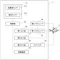
図1は、安全装置1及び飛行体2の一例を模式的に表す図である。また、図2は、安全装置1の一例を示す機能ブロック図である。本実施形態に係る安全装置1は、飛行体2の落下を検知し、パラシュート等を用いて着地又は着水時の飛行体2及び着地点付近の構造物等への衝撃を低減させる。飛行体2は、いわゆるドローンと呼ばれるような無人飛行機(UAV:Unmanned Aerial Vehicle)である。飛行体2は、例えば複数の回転翼を備え
るマルチコプターであってもよい。また、飛行体2は、例えば、予め定められたルートを飛行して、荷物を配達するものであってもよいし、搭載するカメラで動画又は静止画を撮影するものであってもよい。 FIG. 1 is a diagram showing an example of a
安全装置1は、センサユニット11と、制御部12と、第1パラシュート13及び第2パラシュート14を格納するパラシュート格納部と、エアバッグ15と、パラシュートの開傘を制御する第1火工品16及び第2火工品17と、エアバッグ15の展開を制御する第3火工品18と、警報装置19とを含む。センサユニット11は、飛行体2の落下を検知するための加速度センサ111と、飛行体2の高度を算出するための気圧センサ112とを含む。また、センサユニット11は、飛行体2の重心近傍に装着される。The
制御部12は、マイクロコントローラのようなプロセッサであり、センサユニット11や、火工品16~18、警報装置19と信号線を介して接続されている。そして、制御部12は、センサユニット11の出力に基づいて安全装置1の制御を行う。なお、制御部12は、センサユニット11内に設けられてもよい。The
第1パラシュート13は、パイロットシュートであり、第2パラシュート14は、メインパラシュートである。すなわち、第1パラシュート13のパラシュートコードは第2パラシュート14の傘頂部に接続され、第1パラシュート13の空気抵抗力によって第2パラシュート14が引き出される。ただし、本実施形態では、第2パラシュート14の開傘を抑止するための抑止部を備え、第1パラシュート13と第2パラシュート14とは、それぞれ制御部12の制御に応じたタイミングで開傘するようになっている。具体的には、第1パラシュート13は、抑止部として機能するワイヤーを介して例えばパラシュート格納部に接続される。そして、ワイヤーは、切断されるまで、第1パラシュート13が第2パラシュート14を引き出すことを抑止する。The
また、エアバッグ15は、飛行体2の下部に装着され、着地又は着水の衝撃を軽減する。エアバッグ15は、自動車などに搭載されている公知のエアバッグ装置で使用しているものを使用することができる。なお、エアバッグ15はガスを排出するためのベント口は有しない方が、着水時に飛行体2を長時間浮かせることができるため好ましい。また、エアバッグ15の膨張展開後の形状は特に制限されるものではなく、飛行体2の構造および形状に応じて適宜選択することができる。例えば、球状、扁球状(円板状)、平面視において楕円状の扁平な球状、多面体状、なす形状、棒状、浮き輪状、舟形、又はこれらのエアバッグが1箇所以上で複数接続される形状(例えば、ヨットの双胴艇や三胴艇のような形状)等にすることができる。The
第1火工品16は、筒状の筐体から、第1パラシュート13の傘頂部と接続された錘を、点火器から受けるエネルギーによりスラグ弾のように発射するガンスラグを形成する。図3は、第1火工品16、第1パラシュート13及び第2パラシュート14の構成を説明するための図である。第1火工品16は、シリンダ状の筐体に、点火器161と錘162
とを備える。また、錘162は、折り畳まれた第1パラシュート13の傘頂部に接続されている。そして、図示していない抵抗体に通電させ、点火器161に点火されることにより発生するガス圧により、錘162が発射されると、錘162と接続された第1パラシュート13が引き出され、開傘する。なお、第1火工品16は飛行体2の上部に取り付けられ、錘は飛行体2の回転翼と干渉しない方向に発射される。 The first pyrotechnic 16 forms a gun slug that fires a weight connected to the top of the canopy of the
The
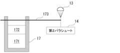
第2火工品17は、筒状の筐体内に保持するピストンを点火器から受けるエネルギーにより作動させ、上述したワイヤーを切断するワイヤーカッターを形成する。図4は、第2火工品17、第1パラシュート13及び第2パラシュート14の構成を説明するための図である。第2火工品17は、シリンダ状の筐体に、点火器171とピストン172とを備える。また、ピストン172の移動方向にはワイヤー173が張られている。また、ワイヤー173は、第1パラシュート13のパラシュートコードに接続され、第1パラシュート13が第2パラシュート14を引き出すことを抑止する。なお、第1パラシュート13のパラシュートコードは、折り畳まれた第2パラシュート14の傘頂部に接続されている。そして、図示していない抵抗体に通電させ、点火器171に点火されることにより発生するガス圧により、ピストン172が移動すると、ワイヤー173を切断し、第1パラシュート13と接続された第2パラシュート14は、第1パラシュート13の空気抵抗力によって引き出され、開傘する。The second
第3火工品18も、内部に点火器を含む火薬式のインフレータ(ガス発生器)であり、袋状のエアバッグ15内にガスを送り込み、エアバッグ15を膨張させる。The third
警報装置19は、例えばLED又はスピーカーを含み、光又は音を発して周囲に飛行体2の落下を知らせる。The
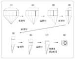
図5は、パラシュートの畳み方の一例を示す図である。パラシュートのキャノピーの形状は特に限定されず、半球型、平面円形型、十字型、ヘキサゴン型等の形状を採用することができる。図5の(1)は、キャノピーを正面視又は側面視した形状に2つ折りにした図である。そして、図5の(1)から(5)に示すように、キャノピーは開傘時の水平方向に複数に等分(図5の例では5等分)され、蛇腹折りにされる。すなわち、(1)から(5)までは、2つ折りにされたキャノピーを合わせて、開傘時の鉛直方向に沿った折り線に沿って、谷折りと山折りとが交互に繰り返される。さらに、図5の(5)から(7)に示すように、キャノピーは開傘時の鉛直方向に複数に等分(図5の例では3等分)され、蛇腹折りにされる。すなわち、(5)から(7)までは、開傘時の水平方向に沿った折り線に沿って、谷折りと山折りとが交互に繰り返される。最後に、図5の(7)から(8)に示すように、吊索(ライン)をまとめる。吊索は、例えば円形に巻いてまとめるようにしてもよい。第1パラシュート13及び第2パラシュート14は、図5に示す手順で折り畳むようにしてもよいし、他の既存の手法により折り畳むようにしてもよい。Figure 5 is a diagram showing an example of how to fold a parachute. The shape of the parachute canopy is not particularly limited, and shapes such as a hemisphere, a flat circular shape, a cross shape, and a hexagonal shape can be adopted. (1) of Figure 5 is a diagram showing a canopy folded in two in a shape seen from the front or side. Then, as shown in (1) to (5) of Figure 5, the canopy is divided into several equal parts in the horizontal direction when the umbrella is opened (five equal parts in the example of Figure 5) and folded in an accordion manner. That is, from (1) to (5), the folded canopy is put together and valley folds and mountain folds are alternately repeated along the folding line along the vertical direction when the umbrella is opened. Furthermore, as shown in (5) to (7) of Figure 5, the canopy is divided into several equal parts in the vertical direction when the umbrella is opened (three equal parts in the example of Figure 5) and folded in an accordion manner. That is, from (5) to (7), valley folds and mountain folds are alternately repeated along the folding line along the horizontal direction when the umbrella is opened. Finally, the slings (lines) are bundled together as shown in (7) and (8) of Figure 5. The slings may be bundled together, for example, by wrapping them in a circle. The
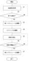
図6は、安全装置1の動作を説明するための処理フロー図である。また、図7は、飛行体2の高度及び経過時間、並びに安全装置1の動作を説明するための図である。なお、図7に示す符号は、図6の工程と対応している。図6に示す処理は、飛行体2の飛行中に、安全装置1が実行する。なお、安全装置1は、上述したセンサユニット11や制御部12に給電する電力供給部(図示せず)を備え、飛行体2からは独立して動作する。すなわち、飛行体2にトラブルが生じた場合も、安全装置1は単独で動作することができる。Figure 6 is a process flow diagram for explaining the operation of the
安全装置1の制御部12は、加速度センサ111が出力する加速度を示すデータを取得する(図6:S1)。加速度センサ111は、所定の周期で3軸方向の加速度に応じた観測値をそれぞれ出力する。一方、制御部12は、3軸方向の加速度を取得し、3軸の合成加速度を算出する。なお、制御部12は、取得した加速度の移動平均を用いて合成加速度
を算出するようにしてもよい。 The
また、制御部12は、取得した加速度を用いて飛行体2の落下を検知する(図6:S2)。本ステップでは、S1において取得した加速度を示すデータが、例えば鉛直下方へ向かう所定の閾値以上の加速度を示す場合、制御部12は飛行体2が落下していると判断する。S2において制御部12が落下を検知しない場合(S2:NO)、S1に戻って処理を繰り返す。The
一方、S2において制御部12が落下を検知した場合(S2:YES)、制御部12は第1火工品16を動作させ、第1パラシュート13を展開させる(図6:S3)。本ステップでは、図3を用いて説明したように、制御部12は第1火工品16に通電させ、発射される錘162に接続された第1パラシュート13を開傘させる。また、S2において制御部12が落下を検知した後に、制御部12は、警報装置19に光又は音を出力させるようにしてもよい。On the other hand, if the
また、制御部12は、所定のタイミングで第3火工品18を動作させ、エアバッグ15を展開させる(図6:S4)。本ステップでは、制御部12は第3火工品18に通電させ、点火器に点火してガスを発生させ、エアバッグ15を膨張させる。なお、エアバッグ15を展開させるタイミングは、飛行体2の着地前であれば特に限定されず、例えばS3の処理から所定時間後であってもよいし、後述するS7と同時であってもよい。The
また、制御部12は、気圧センサ112が出力する気圧を示すデータを取得し、飛行体2の高度を算出する(図6:S5)。気圧センサ112は、所定の周期で気圧に応じた観測値を出力する。一方、制御部12は、気圧の測定値と高度との関係を示す既知の関数を用いて飛行体2の高度を算出する。なお、制御部12は、取得した気圧の移動平均を用いてノイズを除去するようにしてもよい。また、制御部12は、例えばカルマンフィルターを用いて気圧の値を推定するようにしてもよい。The
そして、制御部12は、高度が所定の閾値以下であるか判断する(図6:S6)。本ステップでは、制御部12は、S5で算出された高度が予め定められた閾値以下であるか判断する。S6において高度が所定の閾値以下でないと判断された場合(S6:NO)、S5に戻って処理を繰り返す。Then, the
一方、S6において高度が所定の閾値以下であると判断された場合(S6:YES)、制御部12は、第2火工品17を動作させ、第2パラシュート14を展開させる(図6:S7)。本ステップでは、図4を用いて説明したように、制御部12は第2火工品17に通電させ、ピストン172がワイヤー173を切断すると、第2パラシュート14は第1パラシュート13の空気抵抗力によって引き出され、開傘する。On the other hand, if it is determined in S6 that the altitude is equal to or lower than the predetermined threshold (S6: YES), the
<効果>
図7に示すように、S3において第1パラシュート13が開傘させられると、飛行体2の落下速度を減衰すると共に飛行体2の落下時の姿勢が制御される。このときメインパラシュートである第2パラシュート14を開傘させてしまうと、例えば横風に流されて当初の飛行経路から大きく外れた場所に着地するおそれがある。すなわち、周囲の建造物や電線、通行人などに接触する可能性が高まる。本実施形態では、飛行体2が所定の高度以下に降下するまで第2パラシュート14は開傘させられないため、飛行体の墜落時に着地点を制御し得る。すなわち、第1パラシュート13とは異なるタイミングで、第2パラシュート14を開傘させるよう制御することで、当初の飛行経路からそれほど遠くない場所に飛行体2を着地させ得る。また、S7において第2パラシュート14を展開することにより、飛行体2の着地時の衝撃を十分に低減させることができる。<Effects>
As shown in FIG. 7, when the
したがって、本実施形態に係る安全装置1によれば、例えば自動操縦によりあらかじめ定められた飛行ルートや配達ルートに近い位置に飛行体2を着地させることができ、飛行体2の墜落時においても安全性を向上させることができる。また、飛行体が運搬する荷物や、飛行体に搭載されるカメラ等の機器を保護することができる。Therefore, the
<その他>
上述した安全装置1は、様々な種類の飛行体2に取り付けることができる。また、上述した高度の閾値に基づく第2パラシュート14の開傘タイミングや、エアバッグ15の展開タイミング等、上述したシーケンス制御は、例えば飛行体2の種別に応じて予め好ましい設定を定義しておき、飛行体2の種別に応じて適用できるようにしてもよい。<Other>
The above-described
以上、本開示に係る電流回路遮断装置の実施形態および変形例について説明したが、上述した各実施形態および変形例は可能な限り組み合わせることができる。また、例えばエアバッグ15や、警報装置19等、図2に示した構成の一部は、本開示の趣旨を逸脱しない範囲で削除することができる。The above describes the embodiments and modifications of the current circuit interruption device according to the present disclosure, but the above-mentioned embodiments and modifications can be combined as much as possible. In addition, some of the components shown in FIG. 2, such as the
1:安全装置
11:センサユニット
111:加速度センサ
112:気圧センサ
12:制御部
13:第1パラシュート
14:第2パラシュート
15:エアバッグ
16:第1火工品
161:点火器
162:錘
17:第2火工品
171:点火器
172:ピストン
173:ワイヤー
18:第3火工品
19:警報装置
2:飛行体1: Safety device 11: Sensor unit 111: Acceleration sensor 112: Air pressure sensor 12: Control unit 13: First parachute 14: Second parachute 15: Airbag 16: First pyrotechnic 161: Igniter 162: Weight 17: Second pyrotechnic 171: Igniter 172: Piston 173: Wire 18: Third pyrotechnic 19: Alarm device 2: Flying object
Claims (10)
Translated fromJapanese落下速度を減衰させると共に前記飛行体の落下時の姿勢を制御する第1のパラシュートと、
前記第1のパラシュートと接続されており、前記飛行体の着地時の衝撃を低減させる第2のパラシュートと、
前記飛行体の落下を検知するセンサ部と、
前記第1のパラシュート及び前記第2のパラシュートの開傘を制御し、前記センサ部が落下を検知した後の第1のタイミングで前記第1のパラシュートを開傘させると共に、前記第1のタイミングの後であって、さらに所定の条件を満たす第2のタイミングで前記第2のパラシュートを開傘させる制御部と、
前記制御部による制御によって作動し、前記第1のパラシュートと接続された錘を射出するための第1の火工品と、
前記第2のパラシュートに先行して開傘した前記第1のパラシュートの空気抵抗力に抗して前記第2のパラシュートの開傘を抑止するための抑止部と、
前記制御部による制御によって作動し、前記抑止部による前記第2のパラシュートの開傘の抑止を解除する第2の火工品と、
を備え、
前記第2の火工品が作動することにより、第2のパラシュートが、第1のパラシュートの空気抵抗力によって引き出されて開傘する、
安全装置。 A safety device provided on an aircraft,
a first parachute that reduces the falling speed and controls the attitude of the flying object when it falls;
a second parachuteconnected to the first parachute and configured to reduce an impact when the aircraft lands;
A sensor unit that detects the fall of the flying object;
a control unit that controls the opening of the first parachute and the second parachute, opening the first parachute at a first timing after the sensor unit detects a fall, and opening the second parachute at a second timing that is after the first timing and satisfies a predetermined condition ;
a first pyrotechnic device that is operated under control of the control unit and that ejects a weight connected to the first parachute;
a suppression unit for suppressing the opening of the second parachute against the air resistance of the first parachute that opens prior to the opening of the second parachute;
a second pyrotechnic device that is operated under the control of the control unit and releases the inhibition of the second parachute from opening by the inhibition unit;
Equipped with
When the second pyrotechnic device is activated, the second parachute is pulled out by the air resistance of the first parachute and opens.
Safety device.
前記第1のパラシュートは、前記複数の回転翼と干渉しない方向に射出される
請求項1に記載の安全装置。 The flying object is a multicopter having a plurality of rotors,
The safety device according to claim1 , wherein the first parachute is ejected in a direction that does not interfere with the plurality of rotors.
前記第2の火工品は、発射体を射出して前記ワイヤーを切断するワイヤーカッターである
請求項1又は2に記載の安全装置。 the restraining portion includes a wire connected to the first parachute or the second parachute,
3. The safety device according to claim1 or 2 , wherein the second pyrotechnic device is a wire cutter that ejects a projectile to cut the wire.
請求項1から3のいずれか一項に記載の安全装置。 The safety device according to claim1 , wherein the predetermined condition can be set to be different depending on the type of the flying object.
前記所定の条件は、前記センサ部が測定した前記飛行体の高度が所定の閾値よりも低いことである
請求項1から4のいずれか一項に記載の安全装置。 The sensor unit further measures the altitude of the aircraft,
The safety device according to claim1 , wherein the predetermined condition is that the altitude of the flying object measured by the sensor unit is lower than a predetermined threshold value.
請求項1から5のいずれか一項に記載の安全装置。 The safety device according to claim1 , further comprising an alarm unit that emits sound or light when the sensor unit detects a fall.
請求項1から6のいずれか一項に記載の安全装置。 The safety device according to claim1 , further comprising an airbag that is deployed at a predetermined timing when the sensor unit detects a fall.
請求項7に記載の安全装置。 8. The safety device of claim7 , wherein the airbag does not have a vent for venting gas.
請求項1から8のいずれか一項に記載の安全装置。 The safety device according to claim1 , further comprising a power supply unit that supplies power to the sensor unit and the control unit.
Priority Applications (5)
| Application Number | Priority Date | Filing Date | Title |
|---|---|---|---|
| JP2021015136AJP7580288B2 (en) | 2021-02-02 | 2021-02-02 | Safety devices and flying vehicles |
| PCT/JP2022/003597WO2022168793A1 (en) | 2021-02-02 | 2022-01-31 | Safety device and flight vehicle |
| CN202280011843.4ACN116867707A (en) | 2021-02-02 | 2022-01-31 | Safety device and flying body |
| EP22749665.0AEP4289727A4 (en) | 2021-02-02 | 2022-01-31 | SAFETY DEVICE AND AIRCRAFT |
| US18/228,944US20230373666A1 (en) | 2021-02-02 | 2023-08-01 | Safety device and flight vehicle |
Applications Claiming Priority (1)
| Application Number | Priority Date | Filing Date | Title |
|---|---|---|---|
| JP2021015136AJP7580288B2 (en) | 2021-02-02 | 2021-02-02 | Safety devices and flying vehicles |
Publications (2)
| Publication Number | Publication Date |
|---|---|
| JP2022118547A JP2022118547A (en) | 2022-08-15 |
| JP7580288B2true JP7580288B2 (en) | 2024-11-11 |
Family
ID=82741349
Family Applications (1)
| Application Number | Title | Priority Date | Filing Date |
|---|---|---|---|
| JP2021015136AActiveJP7580288B2 (en) | 2021-02-02 | 2021-02-02 | Safety devices and flying vehicles |
Country Status (5)
| Country | Link |
|---|---|
| US (1) | US20230373666A1 (en) |
| EP (1) | EP4289727A4 (en) |
| JP (1) | JP7580288B2 (en) |
| CN (1) | CN116867707A (en) |
| WO (1) | WO2022168793A1 (en) |
Families Citing this family (1)
| Publication number | Priority date | Publication date | Assignee | Title |
|---|---|---|---|---|
| CN114502463B (en)* | 2021-06-16 | 2025-01-03 | 深圳市大疆创新科技有限公司 | Control method and device of unmanned aerial vehicle system, unmanned aerial vehicle system and storage medium |
Citations (5)
| Publication number | Priority date | Publication date | Assignee | Title |
|---|---|---|---|---|
| US20030197095A1 (en) | 2001-12-07 | 2003-10-23 | Daniel Preston | Steerable parachute control system and method |
| JP2007182182A (en) | 2006-01-10 | 2007-07-19 | Ihi Aerospace Co Ltd | Return member recovery method and recovery device for high speed return |
| JP2010018264A (en) | 2008-06-09 | 2010-01-28 | Technical Research & Development Institute Ministry Of Defence | Parachute mounting device |
| JP2018193055A (en) | 2017-05-16 | 2018-12-06 | 日本化薬株式会社 | Expand device of parachute or paraglider, and flying object therewith |
| CN212243847U (en) | 2019-12-31 | 2020-12-29 | 深圳市天鹰装备科技有限公司 | Umbrella rope cutter and control circuit |
Family Cites Families (10)
| Publication number | Priority date | Publication date | Assignee | Title |
|---|---|---|---|---|
| US3079113A (en)* | 1960-10-04 | 1963-02-26 | Jr Andre J Meyer | Vehicle parachute and equipment jettison system |
| JPH0415499A (en)* | 1990-05-08 | 1992-01-20 | Mitsubishi Heavy Ind Ltd | Object dropping device |
| JP6771735B2 (en) | 2016-06-28 | 2020-10-21 | 津田 訓範 | Aircraft with parachute system and parachute system |
| US11459113B2 (en)* | 2016-07-11 | 2022-10-04 | Kitty Hawk Corporation | Multimodal aircraft recovery system |
| JP6813997B2 (en) | 2016-09-02 | 2021-01-13 | 株式会社ダイセル | Small aircraft with airbag device |
| US10577111B2 (en)* | 2016-10-28 | 2020-03-03 | Kitty Hawk Corporation | Bimodal parachute deployment system |
| TWI610852B (en)* | 2016-12-20 | 2018-01-11 | Aircraft parachute device | |
| JP6446491B2 (en) | 2017-03-17 | 2018-12-26 | 東芝電波プロダクツ株式会社 | Drone safety device and method and drone |
| CN111295334B (en) | 2017-08-24 | 2024-06-07 | 日本化药株式会社 | Safety device for flying body and flying body |
| JP2020104803A (en)* | 2018-12-28 | 2020-07-09 | キヤノンマーケティングジャパン株式会社 | Unmanned aircraft, method for controlling unmanned aircraft and program |
- 2021
- 2021-02-02JPJP2021015136Apatent/JP7580288B2/enactiveActive
- 2022
- 2022-01-31CNCN202280011843.4Apatent/CN116867707A/enactivePending
- 2022-01-31WOPCT/JP2022/003597patent/WO2022168793A1/ennot_activeCeased
- 2022-01-31EPEP22749665.0Apatent/EP4289727A4/enactivePending
- 2023
- 2023-08-01USUS18/228,944patent/US20230373666A1/ennot_activeAbandoned
Patent Citations (5)
| Publication number | Priority date | Publication date | Assignee | Title |
|---|---|---|---|---|
| US20030197095A1 (en) | 2001-12-07 | 2003-10-23 | Daniel Preston | Steerable parachute control system and method |
| JP2007182182A (en) | 2006-01-10 | 2007-07-19 | Ihi Aerospace Co Ltd | Return member recovery method and recovery device for high speed return |
| JP2010018264A (en) | 2008-06-09 | 2010-01-28 | Technical Research & Development Institute Ministry Of Defence | Parachute mounting device |
| JP2018193055A (en) | 2017-05-16 | 2018-12-06 | 日本化薬株式会社 | Expand device of parachute or paraglider, and flying object therewith |
| CN212243847U (en) | 2019-12-31 | 2020-12-29 | 深圳市天鹰装备科技有限公司 | Umbrella rope cutter and control circuit |
Also Published As
| Publication number | Publication date |
|---|---|
| EP4289727A4 (en) | 2024-11-20 |
| CN116867707A (en) | 2023-10-10 |
| WO2022168793A1 (en) | 2022-08-11 |
| US20230373666A1 (en) | 2023-11-23 |
| JP2022118547A (en) | 2022-08-15 |
| EP4289727A1 (en) | 2023-12-13 |
Similar Documents
| Publication | Publication Date | Title |
|---|---|---|
| JP7232374B2 (en) | flying object | |
| JP6813997B2 (en) | Small aircraft with airbag device | |
| US20250147507A1 (en) | Automated aircraft recovery system | |
| CN103547506A (en) | Buoyancy system | |
| JP7191090B2 (en) | Actuating device for flying object, method for preventing malfunction of operating device for flying object, thrust generating device for flying object, deploying device for parachute or paraglider, and airbag device | |
| US11919650B2 (en) | Multimodal aircraft recovery system | |
| EP3481722B1 (en) | Multi-rocket parachute deployment system | |
| US20230373666A1 (en) | Safety device and flight vehicle | |
| JP2020040512A (en) | Airbag device and unmanned aerial vehicle equipped with the same | |
| US8800923B2 (en) | Method of activating protection means for protecting an occupant of an aircraft, and an aircraft implementing said method | |
| KR200166871Y1 (en) | A device of emergency escape foraircraft | |
| NZ749620B (en) | Multi-rocket parachute deployment system |
Legal Events
| Date | Code | Title | Description |
|---|---|---|---|
| A621 | Written request for application examination | Free format text:JAPANESE INTERMEDIATE CODE: A621 Effective date:20231212 | |
| A131 | Notification of reasons for refusal | Free format text:JAPANESE INTERMEDIATE CODE: A131 Effective date:20240528 | |
| A521 | Request for written amendment filed | Free format text:JAPANESE INTERMEDIATE CODE: A523 Effective date:20240723 | |
| TRDD | Decision of grant or rejection written | ||
| A01 | Written decision to grant a patent or to grant a registration (utility model) | Free format text:JAPANESE INTERMEDIATE CODE: A01 Effective date:20241022 | |
| A61 | First payment of annual fees (during grant procedure) | Free format text:JAPANESE INTERMEDIATE CODE: A61 Effective date:20241029 | |
| R150 | Certificate of patent or registration of utility model | Ref document number:7580288 Country of ref document:JP Free format text:JAPANESE INTERMEDIATE CODE: R150 |