JP7579637B2 - Embolic Filter System - Google Patents
Embolic Filter SystemDownload PDFInfo
- Publication number
- JP7579637B2 JP7579637B2JP2019539263AJP2019539263AJP7579637B2JP 7579637 B2JP7579637 B2JP 7579637B2JP 2019539263 AJP2019539263 AJP 2019539263AJP 2019539263 AJP2019539263 AJP 2019539263AJP 7579637 B2JP7579637 B2JP 7579637B2
- Authority
- JP
- Japan
- Prior art keywords
- filter
- elongate element
- embolic
- elongate
- examples
- Prior art date
- Legal status (The legal status is an assumption and is not a legal conclusion. Google has not performed a legal analysis and makes no representation as to the accuracy of the status listed.)
- Active
Links
- 230000003073embolic effectEffects0.000titleclaimsdescription221
- 210000004369bloodAnatomy0.000claimsdescription124
- 239000008280bloodSubstances0.000claimsdescription124
- 239000012528membraneSubstances0.000claimsdescription38
- 238000000034methodMethods0.000claimsdescription24
- 229920000295expanded polytetrafluoroethylenePolymers0.000claimsdescription18
- 230000017531blood circulationEffects0.000claimsdescription14
- 230000033001locomotionEffects0.000claimsdescription4
- 238000013519translationMethods0.000claimsdescription4
- 108091005804PeptidasesProteins0.000claimsdescription3
- 239000004365ProteaseSubstances0.000claimsdescription3
- 102100037486Reverse transcriptase/ribonuclease HHuman genes0.000claimsdescription3
- 238000004891communicationMethods0.000claimsdescription3
- 239000012530fluidSubstances0.000claimsdescription3
- 239000000463materialSubstances0.000description75
- 230000000452restraining effectEffects0.000description61
- 210000005166vasculatureAnatomy0.000description47
- 239000000835fiberSubstances0.000description32
- 230000002439hemostatic effectEffects0.000description29
- 230000007246mechanismEffects0.000description23
- 229920002313fluoropolymerPolymers0.000description19
- 239000004811fluoropolymerSubstances0.000description19
- 210000002376aorta thoracicAnatomy0.000description14
- 230000035699permeabilityEffects0.000description14
- -1but not limited toSubstances0.000description13
- 239000011248coating agentSubstances0.000description12
- 238000000576coating methodMethods0.000description12
- 238000010586diagramMethods0.000description12
- 229920001343polytetrafluoroethylenePolymers0.000description9
- 239000004810polytetrafluoroethyleneSubstances0.000description9
- 238000001914filtrationMethods0.000description8
- 239000011148porous materialSubstances0.000description7
- 229920000642polymerPolymers0.000description6
- 230000000717retained effectEffects0.000description6
- 230000007704transitionEffects0.000description6
- 239000004698PolyethyleneSubstances0.000description4
- 239000004743PolypropyleneSubstances0.000description4
- 229920000573polyethylenePolymers0.000description4
- 229920001155polypropylenePolymers0.000description4
- 210000003270subclavian arteryAnatomy0.000description4
- 239000004677NylonSubstances0.000description3
- 210000003484anatomyAnatomy0.000description3
- 210000000709aortaAnatomy0.000description3
- 238000013459approachMethods0.000description3
- 210000001715carotid arteryAnatomy0.000description3
- 229920001577copolymerPolymers0.000description3
- 238000012986modificationMethods0.000description3
- 230000004048modificationEffects0.000description3
- HLXZNVUGXRDIFK-UHFFFAOYSA-Nnickel titaniumChemical compound[Ti].[Ti].[Ti].[Ti].[Ti].[Ti].[Ti].[Ti].[Ti].[Ti].[Ti].[Ni].[Ni].[Ni].[Ni].[Ni].[Ni].[Ni].[Ni].[Ni].[Ni].[Ni].[Ni].[Ni].[Ni]HLXZNVUGXRDIFK-UHFFFAOYSA-N0.000description3
- 229910001000nickel titaniumInorganic materials0.000description3
- 229920001778nylonPolymers0.000description3
- 239000004417polycarbonateSubstances0.000description3
- 229920000515polycarbonatePolymers0.000description3
- 230000008901benefitEffects0.000description2
- 239000000560biocompatible materialSubstances0.000description2
- 210000004204blood vesselAnatomy0.000description2
- 230000000295complement effectEffects0.000description2
- 230000006870functionEffects0.000description2
- 230000000670limiting effectEffects0.000description2
- 239000002245particleSubstances0.000description2
- 239000012466permeateSubstances0.000description2
- 239000002861polymer materialSubstances0.000description2
- 208000005189EmbolismDiseases0.000description1
- 239000004696Poly ether ether ketoneSubstances0.000description1
- 239000004952PolyamideSubstances0.000description1
- 230000002411adverseEffects0.000description1
- 210000001367arteryAnatomy0.000description1
- 230000004888barrier functionEffects0.000description1
- 238000005452bendingMethods0.000description1
- 230000009286beneficial effectEffects0.000description1
- 230000008081blood perfusionEffects0.000description1
- 210000001772blood plateletAnatomy0.000description1
- 230000000747cardiac effectEffects0.000description1
- 238000010276constructionMethods0.000description1
- 239000002872contrast mediaSubstances0.000description1
- 230000008878couplingEffects0.000description1
- 238000010168coupling processMethods0.000description1
- 238000005859coupling reactionMethods0.000description1
- 230000003247decreasing effectEffects0.000description1
- 229940124447delivery agentDrugs0.000description1
- 238000003745diagnosisMethods0.000description1
- 238000012377drug deliveryMethods0.000description1
- 230000000694effectsEffects0.000description1
- 210000003743erythrocyteAnatomy0.000description1
- 230000023597hemostasisEffects0.000description1
- 230000002452interceptive effectEffects0.000description1
- 238000003475laminationMethods0.000description1
- 238000003698laser cuttingMethods0.000description1
- 210000000265leukocyteAnatomy0.000description1
- 229910052751metalInorganic materials0.000description1
- 239000002184metalSubstances0.000description1
- 229910001092metal group alloyInorganic materials0.000description1
- 150000002739metalsChemical class0.000description1
- 230000005012migrationEffects0.000description1
- 238000013508migrationMethods0.000description1
- RVTZCBVAJQQJTK-UHFFFAOYSA-Noxygen(2-);zirconium(4+)Chemical compound[O-2].[O-2].[Zr+4]RVTZCBVAJQQJTK-UHFFFAOYSA-N0.000description1
- 230000000149penetrating effectEffects0.000description1
- 230000010412perfusionEffects0.000description1
- 230000002093peripheral effectEffects0.000description1
- 210000002381plasmaAnatomy0.000description1
- 239000004033plasticSubstances0.000description1
- 229920003023plasticPolymers0.000description1
- 229920002647polyamidePolymers0.000description1
- 229920002530polyetherether ketonePolymers0.000description1
- 230000008569processEffects0.000description1
- 230000002829reductive effectEffects0.000description1
- 230000008439repair processEffects0.000description1
- 230000000250revascularizationEffects0.000description1
- 239000012781shape memory materialSubstances0.000description1
- 239000010935stainless steelSubstances0.000description1
- 229910001220stainless steelInorganic materials0.000description1
- 238000013151thrombectomyMethods0.000description1
- 230000002792vascularEffects0.000description1
Images


Classifications
- A—HUMAN NECESSITIES
- A61—MEDICAL OR VETERINARY SCIENCE; HYGIENE
- A61F—FILTERS IMPLANTABLE INTO BLOOD VESSELS; PROSTHESES; DEVICES PROVIDING PATENCY TO, OR PREVENTING COLLAPSING OF, TUBULAR STRUCTURES OF THE BODY, e.g. STENTS; ORTHOPAEDIC, NURSING OR CONTRACEPTIVE DEVICES; FOMENTATION; TREATMENT OR PROTECTION OF EYES OR EARS; BANDAGES, DRESSINGS OR ABSORBENT PADS; FIRST-AID KITS
- A61F2/00—Filters implantable into blood vessels; Prostheses, i.e. artificial substitutes or replacements for parts of the body; Appliances for connecting them with the body; Devices providing patency to, or preventing collapsing of, tubular structures of the body, e.g. stents
- A61F2/01—Filters implantable into blood vessels
- A61F2/013—Distal protection devices, i.e. devices placed distally in combination with another endovascular procedure, e.g. angioplasty or stenting
- A—HUMAN NECESSITIES
- A61—MEDICAL OR VETERINARY SCIENCE; HYGIENE
- A61B—DIAGNOSIS; SURGERY; IDENTIFICATION
- A61B17/00—Surgical instruments, devices or methods
- A61B17/22—Implements for squeezing-off ulcers or the like on inner organs of the body; Implements for scraping-out cavities of body organs, e.g. bones; for invasive removal or destruction of calculus using mechanical vibrations; for removing obstructions in blood vessels, not otherwise provided for
- A61B17/221—Gripping devices in the form of loops or baskets for gripping calculi or similar types of obstructions
- A—HUMAN NECESSITIES
- A61—MEDICAL OR VETERINARY SCIENCE; HYGIENE
- A61F—FILTERS IMPLANTABLE INTO BLOOD VESSELS; PROSTHESES; DEVICES PROVIDING PATENCY TO, OR PREVENTING COLLAPSING OF, TUBULAR STRUCTURES OF THE BODY, e.g. STENTS; ORTHOPAEDIC, NURSING OR CONTRACEPTIVE DEVICES; FOMENTATION; TREATMENT OR PROTECTION OF EYES OR EARS; BANDAGES, DRESSINGS OR ABSORBENT PADS; FIRST-AID KITS
- A61F2/00—Filters implantable into blood vessels; Prostheses, i.e. artificial substitutes or replacements for parts of the body; Appliances for connecting them with the body; Devices providing patency to, or preventing collapsing of, tubular structures of the body, e.g. stents
- A61F2/01—Filters implantable into blood vessels
- A61F2/0105—Open ended, i.e. legs gathered only at one side
- A—HUMAN NECESSITIES
- A61—MEDICAL OR VETERINARY SCIENCE; HYGIENE
- A61B—DIAGNOSIS; SURGERY; IDENTIFICATION
- A61B17/00—Surgical instruments, devices or methods
- A61B17/22—Implements for squeezing-off ulcers or the like on inner organs of the body; Implements for scraping-out cavities of body organs, e.g. bones; for invasive removal or destruction of calculus using mechanical vibrations; for removing obstructions in blood vessels, not otherwise provided for
- A61B17/221—Gripping devices in the form of loops or baskets for gripping calculi or similar types of obstructions
- A61B2017/2215—Gripping devices in the form of loops or baskets for gripping calculi or similar types of obstructions having an open distal end
- A—HUMAN NECESSITIES
- A61—MEDICAL OR VETERINARY SCIENCE; HYGIENE
- A61B—DIAGNOSIS; SURGERY; IDENTIFICATION
- A61B2217/00—General characteristics of surgical instruments
- A61B2217/002—Auxiliary appliance
- A61B2217/005—Auxiliary appliance with suction drainage system
- A—HUMAN NECESSITIES
- A61—MEDICAL OR VETERINARY SCIENCE; HYGIENE
- A61F—FILTERS IMPLANTABLE INTO BLOOD VESSELS; PROSTHESES; DEVICES PROVIDING PATENCY TO, OR PREVENTING COLLAPSING OF, TUBULAR STRUCTURES OF THE BODY, e.g. STENTS; ORTHOPAEDIC, NURSING OR CONTRACEPTIVE DEVICES; FOMENTATION; TREATMENT OR PROTECTION OF EYES OR EARS; BANDAGES, DRESSINGS OR ABSORBENT PADS; FIRST-AID KITS
- A61F2/00—Filters implantable into blood vessels; Prostheses, i.e. artificial substitutes or replacements for parts of the body; Appliances for connecting them with the body; Devices providing patency to, or preventing collapsing of, tubular structures of the body, e.g. stents
- A61F2/01—Filters implantable into blood vessels
- A61F2/011—Instruments for their placement or removal
- A—HUMAN NECESSITIES
- A61—MEDICAL OR VETERINARY SCIENCE; HYGIENE
- A61F—FILTERS IMPLANTABLE INTO BLOOD VESSELS; PROSTHESES; DEVICES PROVIDING PATENCY TO, OR PREVENTING COLLAPSING OF, TUBULAR STRUCTURES OF THE BODY, e.g. STENTS; ORTHOPAEDIC, NURSING OR CONTRACEPTIVE DEVICES; FOMENTATION; TREATMENT OR PROTECTION OF EYES OR EARS; BANDAGES, DRESSINGS OR ABSORBENT PADS; FIRST-AID KITS
- A61F2/00—Filters implantable into blood vessels; Prostheses, i.e. artificial substitutes or replacements for parts of the body; Appliances for connecting them with the body; Devices providing patency to, or preventing collapsing of, tubular structures of the body, e.g. stents
- A61F2/01—Filters implantable into blood vessels
- A61F2/013—Distal protection devices, i.e. devices placed distally in combination with another endovascular procedure, e.g. angioplasty or stenting
- A61F2/014—Retrograde blood flow filters, i.e. device inserted against the blood flow direction
- A—HUMAN NECESSITIES
- A61—MEDICAL OR VETERINARY SCIENCE; HYGIENE
- A61F—FILTERS IMPLANTABLE INTO BLOOD VESSELS; PROSTHESES; DEVICES PROVIDING PATENCY TO, OR PREVENTING COLLAPSING OF, TUBULAR STRUCTURES OF THE BODY, e.g. STENTS; ORTHOPAEDIC, NURSING OR CONTRACEPTIVE DEVICES; FOMENTATION; TREATMENT OR PROTECTION OF EYES OR EARS; BANDAGES, DRESSINGS OR ABSORBENT PADS; FIRST-AID KITS
- A61F2/00—Filters implantable into blood vessels; Prostheses, i.e. artificial substitutes or replacements for parts of the body; Appliances for connecting them with the body; Devices providing patency to, or preventing collapsing of, tubular structures of the body, e.g. stents
- A61F2/01—Filters implantable into blood vessels
- A61F2002/016—Filters implantable into blood vessels made from wire-like elements
- A—HUMAN NECESSITIES
- A61—MEDICAL OR VETERINARY SCIENCE; HYGIENE
- A61F—FILTERS IMPLANTABLE INTO BLOOD VESSELS; PROSTHESES; DEVICES PROVIDING PATENCY TO, OR PREVENTING COLLAPSING OF, TUBULAR STRUCTURES OF THE BODY, e.g. STENTS; ORTHOPAEDIC, NURSING OR CONTRACEPTIVE DEVICES; FOMENTATION; TREATMENT OR PROTECTION OF EYES OR EARS; BANDAGES, DRESSINGS OR ABSORBENT PADS; FIRST-AID KITS
- A61F2/00—Filters implantable into blood vessels; Prostheses, i.e. artificial substitutes or replacements for parts of the body; Appliances for connecting them with the body; Devices providing patency to, or preventing collapsing of, tubular structures of the body, e.g. stents
- A61F2/01—Filters implantable into blood vessels
- A61F2002/018—Filters implantable into blood vessels made from tubes or sheets of material, e.g. by etching or laser-cutting
- A—HUMAN NECESSITIES
- A61—MEDICAL OR VETERINARY SCIENCE; HYGIENE
- A61F—FILTERS IMPLANTABLE INTO BLOOD VESSELS; PROSTHESES; DEVICES PROVIDING PATENCY TO, OR PREVENTING COLLAPSING OF, TUBULAR STRUCTURES OF THE BODY, e.g. STENTS; ORTHOPAEDIC, NURSING OR CONTRACEPTIVE DEVICES; FOMENTATION; TREATMENT OR PROTECTION OF EYES OR EARS; BANDAGES, DRESSINGS OR ABSORBENT PADS; FIRST-AID KITS
- A61F2230/00—Geometry of prostheses classified in groups A61F2/00 - A61F2/26 or A61F2/82 or A61F9/00 or A61F11/00 or subgroups thereof
- A61F2230/0063—Three-dimensional shapes
- A61F2230/0067—Three-dimensional shapes conical
- A—HUMAN NECESSITIES
- A61—MEDICAL OR VETERINARY SCIENCE; HYGIENE
- A61F—FILTERS IMPLANTABLE INTO BLOOD VESSELS; PROSTHESES; DEVICES PROVIDING PATENCY TO, OR PREVENTING COLLAPSING OF, TUBULAR STRUCTURES OF THE BODY, e.g. STENTS; ORTHOPAEDIC, NURSING OR CONTRACEPTIVE DEVICES; FOMENTATION; TREATMENT OR PROTECTION OF EYES OR EARS; BANDAGES, DRESSINGS OR ABSORBENT PADS; FIRST-AID KITS
- A61F2230/00—Geometry of prostheses classified in groups A61F2/00 - A61F2/26 or A61F2/82 or A61F9/00 or A61F11/00 or subgroups thereof
- A61F2230/0063—Three-dimensional shapes
- A61F2230/0069—Three-dimensional shapes cylindrical
- A—HUMAN NECESSITIES
- A61—MEDICAL OR VETERINARY SCIENCE; HYGIENE
- A61F—FILTERS IMPLANTABLE INTO BLOOD VESSELS; PROSTHESES; DEVICES PROVIDING PATENCY TO, OR PREVENTING COLLAPSING OF, TUBULAR STRUCTURES OF THE BODY, e.g. STENTS; ORTHOPAEDIC, NURSING OR CONTRACEPTIVE DEVICES; FOMENTATION; TREATMENT OR PROTECTION OF EYES OR EARS; BANDAGES, DRESSINGS OR ABSORBENT PADS; FIRST-AID KITS
- A61F2250/00—Special features of prostheses classified in groups A61F2/00 - A61F2/26 or A61F2/82 or A61F9/00 or A61F11/00 or subgroups thereof
- A61F2250/0014—Special features of prostheses classified in groups A61F2/00 - A61F2/26 or A61F2/82 or A61F9/00 or A61F11/00 or subgroups thereof having different values of a given property or geometrical feature, e.g. mechanical property or material property, at different locations within the same prosthesis
- A61F2250/0023—Special features of prostheses classified in groups A61F2/00 - A61F2/26 or A61F2/82 or A61F9/00 or A61F11/00 or subgroups thereof having different values of a given property or geometrical feature, e.g. mechanical property or material property, at different locations within the same prosthesis differing in porosity
- A61F2250/0024—Special features of prostheses classified in groups A61F2/00 - A61F2/26 or A61F2/82 or A61F9/00 or A61F11/00 or subgroups thereof having different values of a given property or geometrical feature, e.g. mechanical property or material property, at different locations within the same prosthesis differing in porosity made from both porous and non-porous parts, e.g. adjacent parts
- A—HUMAN NECESSITIES
- A61—MEDICAL OR VETERINARY SCIENCE; HYGIENE
- A61F—FILTERS IMPLANTABLE INTO BLOOD VESSELS; PROSTHESES; DEVICES PROVIDING PATENCY TO, OR PREVENTING COLLAPSING OF, TUBULAR STRUCTURES OF THE BODY, e.g. STENTS; ORTHOPAEDIC, NURSING OR CONTRACEPTIVE DEVICES; FOMENTATION; TREATMENT OR PROTECTION OF EYES OR EARS; BANDAGES, DRESSINGS OR ABSORBENT PADS; FIRST-AID KITS
- A61F2250/00—Special features of prostheses classified in groups A61F2/00 - A61F2/26 or A61F2/82 or A61F9/00 or A61F11/00 or subgroups thereof
- A61F2250/0014—Special features of prostheses classified in groups A61F2/00 - A61F2/26 or A61F2/82 or A61F9/00 or A61F11/00 or subgroups thereof having different values of a given property or geometrical feature, e.g. mechanical property or material property, at different locations within the same prosthesis
- A61F2250/0039—Special features of prostheses classified in groups A61F2/00 - A61F2/26 or A61F2/82 or A61F9/00 or A61F11/00 or subgroups thereof having different values of a given property or geometrical feature, e.g. mechanical property or material property, at different locations within the same prosthesis differing in diameter
Landscapes
- Health & Medical Sciences (AREA)
- Life Sciences & Earth Sciences (AREA)
- Engineering & Computer Science (AREA)
- Public Health (AREA)
- Veterinary Medicine (AREA)
- Biomedical Technology (AREA)
- Heart & Thoracic Surgery (AREA)
- Vascular Medicine (AREA)
- General Health & Medical Sciences (AREA)
- Animal Behavior & Ethology (AREA)
- Cardiology (AREA)
- Transplantation (AREA)
- Oral & Maxillofacial Surgery (AREA)
- Surgery (AREA)
- Orthopedic Medicine & Surgery (AREA)
- Nuclear Medicine, Radiotherapy & Molecular Imaging (AREA)
- Medical Informatics (AREA)
- Molecular Biology (AREA)
- Surgical Instruments (AREA)
Description
Translated fromJapanese背景
脈管内処置は外科的アプローチよりも低侵襲性又は比較的低侵襲性の手段による脈管内アクセス、診断及び/又は修復を含む幅広い医療ニーズに対処する。幾つかの脈管内処置の間に、塞栓性デブリは脈管構造内で外れたり又は循環したりすることがある。塞栓性デブリの循環は、軽度から極度の脈管系合併症を引き起こし、脳卒中、さらには死亡に至る可能性がある。2. Background Intravascular procedures address a wide range of medical needs including endovascular access, diagnosis and/or repair by less invasive or relatively less invasive means than surgical approaches. During some endovascular procedures, embolic debris may become dislodged or circulate within the vasculature. Circulating embolic debris can cause mild to extreme vascular complications, potentially leading to stroke and even death.
このような脈管内処置に関連して使用される幾つかの従来の塞栓保護デバイスはデバイス内で塞栓性デブリを捕捉する。幾つかの設計では、塞栓性デブリがデバイス中に捕捉された状態で後にデバイスを除去しなければならない。しかしながら、これらの処置の一般的なリスクは除去プロセスの間に、捕捉された塞栓性デブリの一部又は全部が意図せずに脈管構造内に解放されて戻ることである。Some conventional embolic protection devices used in connection with such endovascular procedures trap embolic debris within the device. In some designs, the device must later be removed with the embolic debris trapped within the device. However, a common risk with these procedures is that some or all of the trapped embolic debris may be unintentionally released back into the vasculature during the removal process.
他の幾つかの従来の塞栓保護デバイスは、塞栓性デブリの存在が患者への害の危険性がより低いと考えられる脈管構造の領域に塞栓性デブリの方向を変える。塞栓性デブリの方向変換は、方向変換された塞栓性デブリが別の解剖学的領域に移行する結果として合併症が起こり得るという危険性をはらんでいる。Some other conventional embolic protection devices redirect embolic debris to areas of the vasculature where the presence of embolic debris is believed to pose a lower risk of harm to the patient. Diversion of embolic debris carries the risk that complications may occur as a result of the redirected embolic debris migrating to another anatomical region.
概要
1つの例(「例1」)によれば、塞栓フィルタは、近位端及び遠位端を有する長尺要素と、前記長尺要素の遠位端に配置されているフィルタ部分と、を含み、
ここで、前記長尺要素は第一の構造要素及び第一の被覆材料を含み、前記長尺要素はデリバリーシース内で前進されることを支持するために十分な構造的一体性を有し、ここで、前記フィルタ部分は第二の構造要素及び第二の被覆材料を含み、前記第二の被覆材料の一部は前記フィルタ部分に流入する血液から塞栓性デブリをろ過するように構成された複数の穿孔を含む。According to one example ("Example 1"), an embolic filter includes an elongate element having a proximal end and a distal end, and a filter portion disposed at the distal end of the elongate element;
wherein the elongate element comprises a first structural element and a first covering material, the elongate element having sufficient structural integrity to support being advanced within a delivery sheath, and wherein the filter portion comprises a second structural element and a second covering material, a portion of the second covering material including a plurality of perforations configured to filter embolic debris from blood entering the filter portion.
例1に対するさらに別の例(「例2」)によれば、前記第一の構造要素は自己拡張型ワイヤブレイド(braid)である。According to yet another example ("Example 2") of Example 1, the first structural element is a self-expanding wire braid.
例1~2に対するさらに別の例(「例3」)によれば、前記長尺要素の近位端に加えられる遠位方向の力は、デリバリーシースに対する長尺要素及びフィルタ部分の遠位方向の並進を引き起こすように動作可能である。According to yet another example ("Example 3") of Examples 1-2, a distal force applied to the proximal end of the elongate element is operable to cause distal translation of the elongate element and filter portion relative to the delivery sheath.
例1~3に対するさらに別の例(「例4」)によれば、前記長尺要素は、導入器を必要とせずにデリバリーシース内で前進されるのを支持するのに十分な構造的一体性を有する。According to yet another alternative to Examples 1-3 ("Example 4"), the elongate element has sufficient structural integrity to support being advanced within a delivery sheath without the need for an introducer.
例1~4に対するさらに別の例(「例5」)によれば、前記フィルタ部分は血液透過性であり、前記複数の穿孔は100ミクロンの平均サイズを有する。According to yet another example ("Example 5") to Examples 1-4, the filter portion is blood permeable and the plurality of perforations have an average size of 100 microns.
例1~5に対するさらに別の例(「例6」)によれば、前記フィルタ部分の第二の被覆材料は血液不透過性であり、血液が前記フィルタ部分の第二の被覆材料を通って流れるように動作可能となるように前記第二の被覆材料に複数の穿孔が形成されている。According to yet another example ("Example 6") of Examples 1-5, the second coating material of the filter portion is blood impermeable and has a plurality of perforations formed therein such that blood is operable to flow through the second coating material of the filter portion.
例1~6に対するさらに別の例(「例7」)によれば、前記長尺要素は血液不透過性である。According to yet another example ("Example 7") of Examples 1-6, the elongate element is blood impermeable.
例1~7に対するさらに別の例(「例8」)によれば、前記長尺要素は、臨床処置中に長尺要素の管腔を通る血流を制御するように動作するバルブを通って前進するように構成されている。According to yet another example ("Example 8") to Examples 1-7, the elongate element is configured to advance through a valve that operates to control blood flow through the lumen of the elongate element during a clinical procedure.
例1~8に対するさらに別の例(「例9」)によれば、前記第一及び第二の被覆材料の一方はePTFEを含む。According to yet another example ("Example 9") of Examples 1-8, one of the first and second coating materials includes ePTFE.
別の例(「例10」)によれば、塞栓フィルタは、2つの端部と長尺中間部とを有するフィルタセンブリ、及び、構造要素を含み、ここで、第一の端部において、前記フィルタセンブリは拡張性フレーム及びフィルタ材料を有する拡張性フィルタ要素を含み、ここで、前記中間部は、治療部位へのデリバリーのためにカテーテル管腔内を前進させるために構造要素上に取り付けられるように構成され、そして前記構造要素が取り除かれる間に治療部位に留まるように構成されている、薄い非支持ポリマー材料を含む。According to another example ("Example 10"), an embolic filter includes a filter assembly having two ends and an elongated intermediate portion, and a structural element, where at a first end, the filter assembly includes an expandable filter element having an expandable frame and a filter material, where the intermediate portion includes a thin, unsupported polymeric material configured to be mounted on the structural element for advancement within a catheter lumen for delivery to a treatment site, and configured to remain at the treatment site while the structural element is removed.
例10に対してさらに別の例(「例11」)によれば、前記構造要素は、治療部位での展開のためにカテーテルの端部からフィルタセンブリの第一の端部を前進させるように構成されている。According to yet another example ("Example 11") to Example 10, the structural element is configured to advance a first end of the filter assembly from an end of the catheter for deployment at a treatment site.
例10~11に対するさらに別の例(「例12」)によれば、前記中間部は臨床処置中に中間部の管腔を通る血流を制御するように動作するバルブを通って前進されるように構成されている。According to yet another example ("Example 12") to Examples 10-11, the intermediate section is configured to be advanced through a valve that operates to control blood flow through the lumen of the intermediate section during a clinical procedure.
例12に対するさらに別の例(「例13」)によれば、前記中間部の管腔は、臨床処置中に中間部の管腔を通る1つ以上のメディカルデバイスの前進に適応するように構成されており、前記バルブは、臨床処置中に中間部の管腔を通る血流を制御するように構成されている。According to yet another example ("Example 13") of Example 12, the lumen of the intermediate section is configured to accommodate advancement of one or more medical devices therethrough during a clinical procedure, and the valve is configured to control blood flow through the lumen of the intermediate section during a clinical procedure.
例10~13に対するさらに別の例(「例14」)によれば、前記フィルタ材料は血液透過性であり、100ミクロンの平均サイズを有する複数の穿孔を含む。According to yet another example ("Example 14") to Examples 10-13, the filter material is blood permeable and includes a plurality of perforations having an average size of 100 microns.
例10~14に対するさらに別の例(「例15」)によれば、前記中間部のポリマー材料は血液不透過性である。According to yet another example ("Example 15") of Examples 10-14, the polymer material of the middle portion is blood impermeable.
例10~15に対するさらに別の例(「例16」)によれば、前記フィルタ材料及びポリマー材料の一方はePTFEを含む。According to yet another example ("Example 16") of Examples 10-15, one of the filter material and the polymer material includes ePTFE.
別の例(「例17」)によれば、体内プロテーゼデリバリーデバイスは、カテーテルシャフト上に取り付けられた拡張性フィルタ要素であって、前記拡張性フィルタ要素が展開されたときに前記拡張性フィルタ要素内に捕捉領域を有する拡張性フィルタ要素と、前記拡張性フィルタ要素が治療部位で展開されたときに前記拡張性フィルタ要素を通してそしてそれを超えて延在するように構成されている長尺導管と、を含み、ここで、前記導管は拡張性フィルタ要素を超えて体内プロテアーゼのデリバリーを可能にするように構成されており、ここで、前記長尺導管は前記捕捉領域と前記長尺導管の内部との間の流体連通を提供する少なくとも1つのアパチャを側壁を通して含む。According to another example ("Example 17"), an internal body prosthesis delivery device includes an expandable filter element mounted on a catheter shaft, the expandable filter element having a capture region within the expandable filter element when the expandable filter element is deployed, and an elongate conduit configured to extend through and beyond the expandable filter element when the expandable filter element is deployed at a treatment site, the conduit configured to enable delivery of an internal body protease beyond the expandable filter element, the elongate conduit including at least one aperture through a sidewall providing fluid communication between the capture region and an interior of the elongate conduit.
例17に対するさらに別の例(「例18」)によれば、前記長尺導管は前記カテーテルシャフトから延在している。According to yet another example ("Example 18") of Example 17, the elongate conduit extends from the catheter shaft.
例17~18に対するさらに別の例(「例19」)によれば、前記長尺導管及びカテーテルシャフトは単一のモノリシックユニットを形成している。According to yet another example ("Example 19") of Examples 17-18, the elongate conduit and the catheter shaft form a single monolithic unit.
例17~19に対するさらに別の例(「例20」)によれば、前記少なくとも1つのアパチャは、フィルタ内に捕捉された塞栓性デブリの長尺導管への移動を容易にするように構成されている。According to yet another example ("Example 20") to Examples 17-19, the at least one aperture is configured to facilitate movement of embolic debris trapped within the filter into the elongate conduit.
複数の実施形態は開示されているが、さらに他の実施形態は、例示の実施形態を示しそして記載する以下の詳細な説明から当業者に明らかになるであろう。したがって、図面及び詳細な説明は、本質的に例示的であり、限定的ではないと考えられるべきである。While multiple embodiments are disclosed, still other embodiments will become apparent to those skilled in the art from the following detailed description, which shows and describes illustrative embodiments. Accordingly, the drawings and detailed description are to be regarded as illustrative in nature and not restrictive.
図面の簡単な説明
添付の図面は、本開示のさらなる理解を提供するために含まれ、本明細書に組み込まれてその一部を構成し、例を示し、そして記載と共に本開示の原理を説明するのに役立つ。BRIEF DESCRIPTION OF THE DRAWINGS The accompanying drawings are included to provide a further understanding of the present disclosure, are incorporated in and constitute a part of this specification, illustrate examples, and together with the description, serve to explain the principles of the present disclosure.
詳細な説明
当業者であれば、本開示の様々な態様が、意図された機能を実行するように構成された任意の数の方法及び装置によって実現されうることを容易に理解するであろう。本明細書で参照する添付の図面は必ずしも一定の縮尺通りに描かれているわけではなく、本開示の様々な態様を例示するために誇張されている可能性があり、その点で、図面は限定として解釈されるべきではないことにも留意されたい。様々な例を説明する際に、遠位という用語は、患者の体内の治療領域に近接しているか、あるいはそれに最も近い例示のデバイスに沿った位置を示すために使用される。近位という用語は、デバイスの使用者又は操作者に近接しているか、あるいはそれに最も近い例示のデバイスに沿った位置を示すために使用される。DETAILED DESCRIPTION A person skilled in the art will readily appreciate that the various aspects of the present disclosure may be implemented by any number of methods and devices configured to perform the intended functions. It should also be noted that the accompanying drawings referenced herein are not necessarily drawn to scale and may be exaggerated to illustrate the various aspects of the present disclosure, and in that respect, the drawings should not be construed as limiting. In describing the various examples, the term distal is used to indicate a position along the example device that is proximal or closest to the treatment area within the patient's body. The term proximal is used to indicate a position along the example device that is proximal or closest to the user or operator of the device.
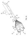
本開示の様々な態様は、塞栓フィルタデバイス、システム及び方法を対象としている。例示の塞栓フィルタシステム1000を図1Aに示す。幾つかの例において、塞栓フィルタシステム1000は遠位端1002及び近位端1004を含む。幾つかの例において、遠位端1002は近位端1004の反対側に位置する。Various aspects of the present disclosure are directed to embolic filter devices, systems, and methods. An exemplary
様々な例において、塞栓フィルタは治療部位に対応する患者の脈管構造の領域で展開される。一般に、システムの1つ以上の構成要素(フィルタ又はデフレクタ部分など)が治療の順行性又は「下流」になるように、システムを標的部位まで前進させる。そのようにしてシステムを配置することは、治療処置中に治療領域から追い払われた塞栓及び他のデブリがシステムに向かって血流と共に移行することを当業者は理解するであろう。このシステムは、展開可能であり、折り畳み(崩潰)可能であり、そして例えば様々なアクセス位置からのデバイスの脈管内除去を容易にするために、遠位又は近位アプローチ方向(例えば、順方向又は逆方向)のいずれかにより脈管構造から除去される。In various examples, the embolic filter is deployed in a region of the patient's vasculature corresponding to the treatment site. In general, the system is advanced to the target site such that one or more components of the system (such as the filter or deflector portion) are antegrade or "downstream" of the treatment. Those skilled in the art will appreciate that positioning the system in this manner will cause emboli and other debris dislodged from the treatment region during the treatment procedure to migrate with the blood flow toward the system. The system is deployable, collapsible, and removable from the vasculature by either a distal or proximal approach direction (e.g., antegrade or retrograde), for example, to facilitate endovascular removal of the device from various access locations.
展開されると、塞栓フィルタシステム1000は、塞栓フィルタシステム1000が展開されている脈管構造の領域を通って流れる血液と相互作用する。幾つかの例において、塞栓フィルタシステム1000は、血液及び/又は塞栓性デブリが塞栓フィルタシステム1000を通って流れるとき又はそれと相互作用するときにそれをろ過するように適応又はさもなければ構成されうる。幾つかの例において、塞栓フィルタシステム1000は、追加的に又は代替的に、さもなければ周囲の脈管構造を通る血液及び/又は塞栓性デブリの通常の又は妨害されていない流れとなっていたであろう血流及び/塞栓性デブリの方向を変える。したがって、様々な例において、塞栓フィルタシステム1000は、血液及び/又は塞栓性デブリが患者の脈管構造のその領域を通って流れるときにろ過及び/又は方向転換されるように、患者の脈管構造の領域内で展開されることができる。When deployed, the
様々な例において、塞栓フィルタシステム1000は、上述のように血流及び塞栓性デブリをろ過及び/又は方向転換するために一緒に動作する1つ以上の構成要素を有する。例えば、ここで図1A及び図1Bを参照すると、塞栓フィルタシステム1000は長尺要素1100、フィルタ1200及び拘束要素1300を含む。拘束要素1300の様々な切り取りが図1A及び1Bになされ、拘束要素1300により見るのを遮っていたはずの長尺要素1100の部分を示している。幾つかの例において、長尺要素1100は、下記に詳細に説明されるように、1つ以上のメディカルデバイスを治療部位にデリバリーすることができる導管として動作する。幾つかの例において、拘束要素1300はカテーテルである。幾つかの例において、患者の体外の1つ以上の構成要素は、長尺要素1100、フィルタ1200及び拘束要素1300に結合されてこれらと共に動作する。例えば、ハンドル、制御ユニット及び/又は止血バルブなどの1つ以上の構成要素1400は、以下により詳細に論じるように、長尺要素1100、フィルタ1200及び拘束要素1300に結合されてよい。様々な例において、フィルタ1200は長尺要素1100に結合され、拘束要素1300は長尺要素1100及びフィルタ1200をデリバリー(又は折り畳み)構成で拘束するように構成される。In various examples, the
様々な例において、長尺要素1100は、遠位端1102、近位端1104、及び、前記遠位端1102と近位端と1104との間に位置する中間部1106を有する長手方向に延在する構造である。幾つかの例において、長尺要素1100は血液及び/又は塞栓性デブリを受け入れるように構成されている。幾つかのそのような例において、長尺要素1100は、塞栓フィルタシステム1000が展開されている患者の脈管構造の部分を通って流れる血液及び塞栓性デブリをろ過及び/又は方向変換する。したがって、様々な例において、長尺要素1100は、管腔1108(図1B)などの内側管腔を含む。幾つかの例において、長尺要素1100に入る血液及び/又は塞栓性デブリは管腔1108を通って流れる。In various examples, the
様々な例において、管腔1108は、長尺要素1100を通って遠位端1102から近位端1104まで延在している。すなわち、幾つかの例において、遠位端1102及び近位端1104は、管腔1108に対して開口している。幾つかの例において、管腔1108は、塞栓フィルタシステム1000に近接する治療部位にまで1つ以上のメディカルデバイスを通過させることができる作業管腔を形成している。したがって、様々な例において、管腔1108はメディカルデバイスデリバリー用の作業管腔として、および血流及び/又は塞栓性デブリの流れを方向変換し及び/又はろ過するための構造として、の両方で動作する。In various examples, the
管腔1108を通過させることができるメディカルデバイスの例としては、限定するわけではないが、カテーテル、血栓切除デバイス、粥腫切除デバイス、塞栓除去デバイス及びそれに関連する器具、造影剤、ドラッグデリバリー剤、例えば、ステント、ステントグラフト及びバルブを含む脈管内プロテーゼが挙げられる。追加的又は代替的に、管腔1108は、以下でさらに説明されるように、1つ以上の解放ライン、ステアリングライン、ガイドワイヤ、構造的支持要素及び/又は導入器ならびに関連構成要素を収容するように構成されている。Examples of medical devices that may be passed through
様々な例において、フィルタ1200は、塞栓フィルタシステム1000が展開されている領域内で患者の脈管構造を通って流れる血液及び/又は塞栓性デブリと相互作用するように構成された構造である。幾つかの例において、フィルタ1200は、血液及び塞栓性デブリがフィルタ1200、そして幾つかの例では長尺要素1100に入るように、血液及び塞栓性デブリを方向付ける又は漏斗状に送り込むように構成されている。In various examples,
様々な例において、フィルタ1200は、遠位端1202、近位端1204及び中間部1206を含む。図1A及び図1Bに示すように、幾つかの例において、フィルタ1200はメンブレン1210及び構造支持体1212を含む。構造支持体1212はニチノール又は他の適切な材料から形成されてよく、レーザーカット、編組(braided)又は巻線されうる。幾つかの例において、当業者に理解されるように、構造支持体1212はレーザーカットされたニチノールチューブから形成されている。In various examples, the
幾つかの例において、メンブレン1210は構造支持体1212の周りに配置されている。幾つかの例において、構造支持体1212はメンブレン1210の周りに配置されている。様々な例において、構造支持体1212はメンブレン1210に構造支持を提供する。幾つかの例において、以下でさらに詳細に論じるように、フィルタ1200は自己拡張型及び/又は半径方向に折り畳み可能である。フィルタ1200は脈管内デリバリー及び展開に適したいかなるサイズのものであってもよい。In some examples, the
幾つかの例において、血液の流れが遠位端1202でフィルタ1200に入り、近位端1204でフィルタ1200を出ることができるように、フィルタ1200の遠位端1202及び近位端1204の両方は開口している。したがって、幾つかの例において、メンブレン1210は、フィルタ1200がそれを通して延在している管腔を有するように構成されている。一般に、この管腔は血液及び塞栓性デブリを捕獲するための領域として動作する。幾つかの例において、フィルタ1200の近位端1204を出る血液が長尺要素1100に入るか、又はさもなければそれと相互作用するように、フィルタ1200の近位端1204は長尺要素1100と結合されている。In some instances, both the
そのような例において、長尺要素1100とフィルタ1200との間の結合は恒久的又は一時的でありうる。幾つかの例において、長尺要素1100は、長尺要素1100とフィルタ1200が単一のモノリシックユニットを形成するようにフィルタ1200に結合されている。幾つかの他の例において、フィルタ1200は長尺要素1100から取り外し可能である。幾つかの例において、フィルタ1200は長尺要素1100に対して摺動可能である。In such examples, the bond between the
幾つかの例において、フィルタ1200は、長尺要素1100の遠位端1102などの長尺要素1100の端部に又はその近くに結合されるか、又はさもなければ固定されている。例えば、図1Aに示す塞栓フィルタシステム1000は、長尺要素1100の遠位端1102に結合されたフィルタ1200を含む。In some examples, the
しかしながら、幾つかの他の例において、フィルタ1200は、長尺要素1100の遠位端1102に対して近位にある長尺要素1100に沿ったある位置で長尺要素1100に結合されている。例えば、図1Bに示す例示された塞栓フィルタシステム1000は、長尺要素1100の遠位端1102に対して近位にある長尺要素1100に沿った位置で長尺要素1100に結合されたフィルタ1200を含む。幾つかのそのような例において、フィルタ1200はフィルタ1200の遠位端1202が長尺要素1100の遠位端1102の近位にあるように長尺要素1100に結合されている。したがって、幾つかの例において、長尺要素1100の遠位端1102は、フィルタ1200の遠位端1202まで遠位に延在しており、したがって、塞栓フィルタシステム1000の遠位端1002に対応しており、又はさもなければそれを画定している。以下により詳細に説明するように、長尺要素1100のそのような遠位に突出している部分は、フィルタ1200と、管腔1108を通して治療部位にデリバリーされるメディカルデバイスとの間の絡み合いから保護する。However, in some other examples, the
幾つかの例において、フィルタ1200は、長尺要素1100の遠位端1102がフィルタ1200の遠位端1202と近位端1204との間に位置するように長尺要素1100に結合されることが理解されるであろう。すなわち、フィルタ1200は、長尺要素1100の遠位端1102に対して近位にある長尺要素1100に沿った位置で長尺要素1100に結合されているが、フィルタ1200の遠位端1202は、塞栓フィルタシステム1000の遠位端1002に対応するか、又はさもなければそれを画定している(すなわち、フィルタ1200の遠位端1202は長尺要素1100の遠位端1102に対して遠位にある)。幾つかの他の例において、フィルタ1200は、長尺要素1100の遠位端1102及びフィルタ1200の遠位端1202が互いに対して等しく遠位に位置するように長尺要素1100に結合されている。言い換えれば、長尺要素1100の遠位端1102は、フィルタ1200の遠位端1202の遠位には配置されておらず(又は実質的には配置されておらず)、その逆も同様である。It will be appreciated that in some instances, the
幾つかの例において、フィルタの近位端は第一の長尺要素の遠位端に結合されており、第二の長尺要素はフィルタ及び/又は第一の長尺要素に結合されて、それにより、第二の長尺要素は第一の長尺要素の遠位でフィルタの内部領域の範囲内又はそれを通して延在している。幾つかの例において、上記の議論と同様に、第二の長尺要素の遠位端は、フィルタの遠位端に対して遠位に、遠位端に、又は遠位端に対して近位に配置される。In some instances, the proximal end of the filter is coupled to the distal end of the first elongate element, and the second elongate element is coupled to the filter and/or the first elongate element such that the second elongate element extends within or through an interior region of the filter distal to the first elongate element. In some instances, similar to the discussion above, the distal end of the second elongate element is disposed distal to, at, or proximal to the distal end of the filter.
幾つかの例において、フィルタ1200は、血液及び/又は塞栓性デブリがフィルタ1200に流れ込むように、血液及び/又は塞栓性デブリを偏向させるか、又はさもなければ方向変換させる。幾つかの例において、フィルタ1200はそれを通っている血液及び塞栓性デブリをろ過し又はさもなければ状態調節するように動作する。幾つかの例において、フィルタ1200は特定の血液媒体に対して透過性(例えば、血液透過性)であり、特定の他の血液媒体及び/又は塞栓性デブリに対して不透過性である。具体的には、幾つかの例において、フィルタ1200のメンブレン1210は、フィルタ1200を通って流れる特定の血液媒体(例えば、赤血球、白血球、血漿、血小板など)がフィルタ1200のメンブレン1210を透過して、脈管構造に再度入り、一方、フィルタ1200は、他の特定の血液媒体及び塞栓性デブリに対して不透過性であるように構成されている。幾つかの例において、フィルタ1200は、指定されたサイズ以上の塞栓性デブリに対して不透過性である。すなわち、幾つかの例において、フィルタ1200のメンブレン1210は、指定されたサイズ以上の塞栓性デブリがフィルタ1200のメンブレン1210を透過して脈管構造に再度入るのを妨げるように動作する。In some instances, the
幾つかの例において、脈管構造内に戻るように透過しないフィルタ1200を通って流れる血液媒体及び塞栓性デブリはフィルタ1200内に捕捉されて保持されるか、又はさらに長尺要素1100内に導かれるかのいずれかである。幾つかの例において、以下により詳細に説明されるように、フィルタ1200は、フィルタ1200内に保持されている血液媒体及び塞栓性デブリが、続いて患者の身体から除去されうるように折り畳み可能である。In some instances, blood media and embolic debris flowing through
上述のように、幾つかの例において、フィルタ1200に流れ込む血液及び/又は塞栓性デブリの一部又は全部はさらに長尺要素1100に向けられる。幾つかの例において、長尺要素1100に向けられる血液及び/又は塞栓性デブリは長尺要素1100の管腔1108に入る。幾つかの例において、以下により詳細に説明されるように、フィルタ1200は、内側管腔1108に入る血液及び/又は塞栓性デブリをろ過するように構成されている。このように、幾つかの例において、長尺要素1100は、フィルタ1200を透過しなかった血液及び/又は塞栓性デブリをろ過するように構成されている。As described above, in some instances, some or all of the blood and/or embolic debris flowing into the
上述のように、幾つかの例において、フィルタ1200及び/又は長尺要素1100は塞栓フィルタシステム1000を通って流れる患者の血液から塞栓性デブリをろ過するように動作する。一般に、長尺要素1100及び/又はメンブレン1210の透過性は長尺要素1100及び/又はメンブレン1210に含まれる材料の材料特性のうちの1つ以上を操作することによって制御することができる。例えば、延伸フルオロポリマーのノードアンドフィブリル構成は、所望の透過性に基づいて最適化することができる。幾つかの例において、延伸フルオロポリマーのノードアンドフィブリル構成が一般に指定されたサイズの塞栓性デブリ(及び他の血液媒体)に対して不透過性であるように、延伸フルオロポリマーを処理することができる。As discussed above, in some examples, the
したがって、長尺要素1100及びフィルタ1200は、限定するわけではないが、延伸ポリテトラフルオロエチレン(「ePTFE」)、延伸PTFE、延伸変性PTFE、PTFEの延伸コポリマーなどのフルオロポリマー、ナイロン、ポリカーボネート、ポリエチレン、ポリプロピレンなどのポリマーを含む様々な材料を含むことができることが理解されうる。Thus, it can be appreciated that the
様々な例において、材料の1つ以上の領域は、その中に1つ以上の穿孔を形成することによってさらに又は代替的に変更されてもよい。例えば、延伸フルオロポリマー(又は別の適切なポリマー)などの材料は、材料の1つ以上の領域を穿孔してそれらの領域に指定の多孔度を達成することによってさらに変更することができる。例としては、材料へのレーザ切断穴又は穿孔が挙げられる。織物、編物又は格子構成を有する他の材料もまた、それらの透過性/多孔度に基づいて適切な材料として役立つことができる。In various examples, one or more regions of a material may be further or alternatively modified by forming one or more perforations therein. For example, a material such as an expanded fluoropolymer (or another suitable polymer) can be further modified by perforating one or more regions of the material to achieve a specified porosity in those regions. Examples include laser cutting holes or perforations into the material. Other materials having woven, knitted, or lattice configurations can also serve as suitable materials based on their permeability/porosity.
さらに、幾つかの例において、材料は、長尺要素1100及び/又はフィルタ1200のメンブレン1210の1つ以上の部分又は領域が、指定されたサイズまでの媒体に対して透過性である一方で、長尺要素1100及び/又はメンブレン1210の1つ以上の他の部分又は領域が媒体に対して不透過性であるように構成されうる。幾つかの例において、長尺要素1100及び/又はフィルタ1200は、例えば、近位端から遠位端まで及び/又は1つ以上の区別される位置(例えば、下記に論じるような1つ以上の透過性窓)で可変の孔又は穿孔サイズを有することができる。例えば、長尺要素1100及び/又はフィルタ1200の遠位領域は、より小さい塞栓性デブリが大きい血管に入るのを避けるために、より小さい平均穿孔サイズを有することができるが、長尺要素1100及び/又はフィルタ1200のより近位の領域は、より小さい塞栓性デブリが大きい血管に入ることが懸念されない点を超えたところで、より大きい平均穿孔サイズを有することができる。Additionally, in some instances, the material may be configured such that one or more portions or regions of the
幾つかの例において、長尺要素1100及び/又はフィルタ1200に沿って材料の層の数を変えることによって、透過性を変えることができる。例えば、第一の数の延伸フルオロポリマーの層を有する材料の第一の領域は第一の程度の透過性と関連付けられ、一方、第二の数の延伸フルオロポリマーの層を有する材料の第二の領域は第二の程度の透過性と関連付けられる。幾つかのそのような例において、そのような材料の領域の透過性は、その領域の材料に組み込まれた延伸フルオロポリマーの層の数に逆相関する。In some examples, the permeability can be varied by varying the number of layers of material along the
幾つかの他の例において、材料の別の領域に対して材料の1つの領域に作られた穿孔の各々の直径又は面積又は穿孔密度を代替的に又は追加的に変えることによって様々な程度の透過性を達成することができる。1つのそのような例において、第一の領域又は区域(例えば、遠位)は、第一の平均穿孔サイズを有する1つ以上の穿孔と関連付けられ、第二の領域又は区域(例えば、近位)は、第二の平均穿孔サイズを有する1つ以上の穿孔と関連付けられることができる。したがって、様々な例において、フィルタ1200及び/又は長尺要素1100は可変孔サイズを有する領域又は区域を含むことができる。孔サイズ又は透過性を変えることによって、塞栓フィルタシステム1000に沿った塞栓性デブリのろ過を制御することができ、潜在的に有害な塞栓性デブリが重要な領域に灌流する危険性を最小限に抑えることができることは理解されるであろう。In some other examples, various degrees of permeability can be achieved by alternatively or additionally varying the diameter or area or perforation density of each of the perforations made in one region of the material relative to another region of the material. In one such example, a first region or area (e.g., distal) can be associated with one or more perforations having a first average perforation size, and a second region or area (e.g., proximal) can be associated with one or more perforations having a second average perforation size. Thus, in various examples, the
様々な例において、上述した穿孔又は孔サイズは、長尺要素1100及び/又はフィルタ1200のメンブレン1210の領域又は区域が約100μm以上の塞栓性デブリに対して不透過性であるように選択されうる。そのような例において、そのような領域の平均孔サイズは100μm未満であることは理解されるであろう。しかしながら、他の例において、孔サイズは、材料の領域又は区域が100μm未満の塞栓性デブリ、例えば、40μm~99μmの範囲の塞栓性デブリに対して不透過性であるように選択されうる。さらに他の例において、材料の他の領域又は区域は、100μmを超える塞栓性デブリ、例えば、101μm~150μmの範囲の塞栓性デブリに対して透過性であることができる。そのような領域の平均孔サイズは、101μm~150μm以上であることは理解されるであろう。In various examples, the perforation or pore sizes described above can be selected such that regions or sections of the
さらに図1A及び図1Bを参照すると、様々な例において、フィルタ1200が展開される脈管の領域(又はその領域の実質的な部分)を占めるように、フィルタ1200は拡張可能である。様々な例において、フィルタ1200は、治療領域にある又は治療領域に近接した標的部位に進められたら拡張される。したがって、様々な例において、フィルタ1200は、半径方向に折り畳まれたデリバリー構成と半径方向に拡張された展開構成との間で移行可能である。幾つかの例において、フィルタ1200は自己拡張型である。幾つかの例において、1つ以上の拡張可能要素を利用して、フィルタ1200を半径方向に折り畳まれたデリバリー構成と半径方向に拡張された展開構成との間で移行させる。例えば、バルーンを利用して、フィルタ1200を半径方向に折り畳まれたデリバリー構成から半径方向に拡張された展開構成に移行させることができる。1A and 1B, in various examples, the
展開構成において、フィルタ1200は、フィルタ1200の横断面積がフィルタ1200の遠位端1202と近位端1202との間のフィルタ1200に沿った2つの異なる位置で異なるという点で、略トランペット型、円錐型又は円錐台形の形状を採用する。1つのそのような例において、遠位端1202の横断面積は、近位端1204の横断面積よりも大きい。幾つかの例において、フィルタ1200は、一般に、遠位端1202から近位端1204に向けてテーパ型になっている。このような構成は、本明細書に開示されるように、フィルタ1200が血液をフィルタ1200及び/又は長尺要素1100内に漏斗状に送り込むように動作することを提供する。In the deployed configuration, the
幾つかの例において、拘束要素1300などの1つ以上の拘束部材は、フィルタ1200及び/又はその一部を半径方向に折り畳まれたデリバリー構成に維持するように動作する。幾つかの例において、フィルタ1200が半径方向に拡張された展開構成に移行可能であるように、拘束要素1300は解放可能又は取り外し可能である。In some examples, one or more restraining members, such as restraining
一般に、所望の構成に応じて、拘束要素1300は、限定するわけではないが、延伸ポリテトラフルオロエチレン(「ePTFE」)、延伸PTFE、延伸変性PTFE、PTFEの延伸コポリマーなどのフルオロポリマー、ナイロン、ポリカーボネート、ポリエチレン、ポリプロピレンなどのポリマーを含む様々な材料を含むことができる。したがって、幾つかの例において、拘束要素1300は、フィルタ1200に対して前進又は後退されることができる。In general, depending on the desired configuration, the restraining
さらに図1A及び図1Bを参照すると、様々な例において、塞栓フィルタシステム1000は拘束要素1300を含む。幾つかの例において、拘束要素1300は遠位端1302及び近位端1304を有する長尺部材である。幾つかの例において、拘束部材1300は円筒形であるが、楕円形の断面を有する拘束要素もまた想定される。様々な例において、内側管腔1306は拘束要素1300を通して遠位端1302から近位端1304まで延在している。幾つかの例において、上述のように、内側管腔1306はその中に長尺要素1100を受け入れるように構成されている。したがって、幾つかのそのような例において、長尺要素1100と拘束要素1300とは同軸である。同様に、様々な例において、フィルタ1200が半径方向に折り畳まれたデリバリー構成に維持されるように、フィルタ1200の一部又は全部は拘束要素1300内に受け入れられている。1A and 1B, in various examples, the
様々な例において、長尺要素1100は、長尺要素1100と拘束要素1300とが互いに対して動くことができるように拘束要素1300内に受け入れられている。以下により詳細に説明されるように、長尺要素1100と拘束要素1300を互いに対して動かすことは、フィルタ1200の展開及び折り畳みの両方を容易にする。In various examples, the
幾つかの例において、拘束要素1300の遠位端1302がフィルタ1200の遠位端1202から離れるように近位方向に並進するように、拘束要素1300は後退可能である。幾つかのそのような例において、長尺要素1100及び/又はフィルタ1200は、拘束要素1300が後退されている間に固定状態に保持される。他の例において、長尺要素1100及び/又はフィルタ1200は、拘束要素1300が後退されている間に前進される。幾つかの例において、長尺要素1100及び/又はフィルタ1200は、フィルタ1200が拘束要素1300の近位端1304から離れるように遠位方向に移動するように拘束要素1300に対して前進される。幾つかの例において、拘束要素1300は、長尺要素1100及び/又はフィルタが前進されている間に、固定状態に保持される。他の例において、長尺要素1100及び/又はフィルタが前進されている間に、拘束要素1300は後退されている。In some instances, the restraining
様々な例において、拘束要素1300の遠位端1302から離れて遠位方向へフィルタ1200が前進することはフィルタ1200の展開を促進する。すなわち、フィルタ1200を拘束要素1300の遠位端1302から離れるように遠位方向に前進させること、及び/又は、拘束要素1300の遠位端1302をフィルタ1200の遠位端1202から離れるように後退させることによって、フィルタ1200は、半径方向に折り畳まれたデリバリー構成から半径方向に拡張された展開構成に移行することができる。In various examples, advancing the
上述のように、幾つかの例において、フィルタ1200は半径方向に拡張された展開構成から半径方向に折り畳まれたデリバリー構成へと移行することができる。幾つかの例において、フィルタ1200を半径方向に折り畳まれたデリバリー構成に移行させて、塞栓フィルタシステム1000を患者の脈管構造から引き出すことができる。幾つかの例において、以下でより詳細に論じるように、フィルタ1200が半径方向に折り畳まれてそして拘束要素1300によって保持されるまで、拘束要素1300をフィルタ1200の遠位端1202に向かって前進させることによって、展開されたフィルタ1200を半径方向に折り畳まれたデリバリー構成に移行させる。代替的に又は追加的に、フィルタ1200は拘束要素1300に対して近位に引き込むことができる。As described above, in some instances, the
上述のように、様々な例において、フィルタ1200は、長尺要素1100の遠位端1102がフィルタ1200の近位端1204に対して遠位に配置されるように、長尺要素1100の遠位端1102に近位にある長尺要素1100に沿った位置で長尺要素1100に結合されている。図1Bを特に参照すると、例示の塞栓フィルタシステム1000は、長尺要素1100の遠位部1110がフィルタ1200の近位端1204を超えて遠位方向に延在するように、フィルタ1200の近位端1204に対して遠位に配置された遠位端1102を有する長尺要素1100を含む。上述のように、様々な例において、長尺要素1100は内側管腔1108を含み、それを通して1つ以上のメディカルデバイスを塞栓フィルタシステム1000の遠位端1002の遠位に位置する治療部位にデリバリーすることができる。As discussed above, in various examples, the
幾つかの例において、遠位部分1110は、そのようなメディカルデバイスがフィルタ1200と絡み合う危険性を少なくしてそのようなメディカルデバイスをデリバリーすることができるということを提供する。言い換えれば、フィルタ1200の近位端1204に対して遠位に延在している長尺要素の部分(遠位部分1110)は、デリバリーされているメディカルデバイスとフィルタ1200との間のバリアとして作用する。したがって、そのような構成は、デリバリーされているメディカルデバイスが長尺要素1100の遠位端1102から出てくるときに、デリバリーされているメディカルデバイスがフィルタ1200と干渉する危険性が減少することと関連がある。当業者であれば、そのような構成はメディカルデバイスがフィルタ1200と絡み合うことによってフィルタ1200が裂けたり又は別の様式で損傷したりする危険性を最小限に抑えるのに役立つことを理解するであろう。In some instances, the
フィルタ1200とデリバリーされているメディカルデバイスとの間の絡み合いに対する保護に加えて、幾つかの例において、長尺要素1100の遠位部分1110は、フィルタが塞栓フィルタシステム1000の除去のために半径方向に折り畳まれるときにフィルタ1200にトラップされた塞栓性材料を捕捉するように作用する。具体的には、幾つかの例において、遠位部分1110は、遠位部分1110の外側表面1114から長尺要素1100の内側管腔1108まで延在している1つ以上のアパチャ1112を含む。したがって、1つ以上のアパチャ1112は管腔1108に入るフィルタ1200により捕捉された塞栓性デブリの通路を提供する。幾つかの例において、そのような構成は、追加的又は代替的に、塞栓フィルタシステム1000からの塞栓性デブリの吸引を容易にする。幾つかのそのような例において、塞栓性デブリの吸引は、フィルタ1200を半径方向に折り畳む及び/又は塞栓フィルタ1000を患者の脈管構造から引き出す前又は後に達成することができる。フィルタ1200内に捕捉されていたはずの塞栓性デブリを排出するための機構を提供することによって、塞栓フィルタシステム1000は、捕捉された塞栓性デブリが患者の脈管構造からの塞栓フィルタシステム1000の引き出し中に誤って患者の脈管構造に解放されて戻る危険性を最小限に抑えるのに役立つことを当業者は理解するであろう。In addition to protecting against entanglement between the
例えば、塞栓性デブリろ過処置中の既知の危険性は、引き出し中にフィルタ(又はフィルタ材料)を引き裂く危険性である。一般に、塞栓性デブリで充填された塞栓フィルタは、一般に、塞栓性デブリのない塞栓フィルタよりも大きな断面積を占める。この増大した断面積は、塞栓フィルタを拘束シース内に完全に引き込むことができる構成に塞栓フィルタを十分に折り畳むことが困難であることと関連しうる。フィルタが拘束シース内に引っ込められていない場合でも、蛇行した脈管構造を通して塞栓性デブリで満たされている結果としてより大きな直径を有するフィルタを引き出すことは困難でありうる。フィルタからの塞栓性デブリの一部又は全部の排出を可能にする機構を提供することは、上記の危険性を最小限に抑えるのに役立つ。For example, a known risk during embolic debris filtration procedures is the risk of tearing the filter (or filter material) during withdrawal. In general, an embolic filter filled with embolic debris generally occupies a larger cross-sectional area than an embolic filter without embolic debris. This increased cross-sectional area may be associated with difficulty in sufficiently collapsing the embolic filter into a configuration that allows it to be fully retracted into the constraining sheath. Even if the filter is not retracted into the constraining sheath, it may be difficult to withdraw a filter having a larger diameter as a result of being filled with embolic debris through a tortuous vasculature. Providing a mechanism that allows for the expulsion of some or all of the embolic debris from the filter helps to minimize the above risk.
幾つかの例において、長尺要素1100の遠位部分1110の断面積は、フィルタ1200の近位端1204の近位に位置する長尺要素1100の部分の断面積よりも小さい。幾つかのそのような例において、長尺要素1100の遠位部分1110は、フィルタ1200の近位端1204の近位に位置する長尺要素1100の部分の外径よりも小さい外径を有する。しかしながら、1つのこのような例において、遠位部分1110の内径は、フィルタ1200の近位端1204の近位に位置する長尺要素1100の部分の内径と同じ(又は実質的に同じ)である。言い換えれば、遠位部分1110の断面積(又は外径)は、フィルタ1200の近位端1204の近位に位置する長尺要素1100の部分のそれよりも小さいが、内側管腔1108の直径又は断面積は、一般に、長尺要素1100の遠位端1102と近位端1104との間で一定である。したがって、幾つかの例において、長尺要素1100はその長さに沿って様々な壁厚を有することが理解されるであろう。In some examples, the cross-sectional area of the
言い換えれば、幾つかの例において、遠位部分1110は第一の内径及び第一の外径を有し、フィルタ1200の近位端1204の近位に位置する長尺要素1100の部分は第一の内径及び第二の外径を有し、ここで、第二の外径は第一の外径よりも大きい。In other words, in some examples, the
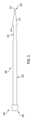
ここで図2及び図3を参照すると、塞栓フィルタシステム2000の様々な構成要素は示されている。図示されるように、塞栓フィルタシステム2000は、長尺要素2100、フィルタ2200(フィルタ1200と同様)及び導入器2300を含む。図4に示されるように、幾つかの例において、塞栓フィルタシステム2000は、拘束部材2400(拘束要素1300と同様)及び止血シール部材2500をさらに含む。2 and 3, various components of
長尺要素1100と同様に、様々な例において、長尺要素2100は、限定するわけではないが、延伸ポリテトラフルオロエチレン(「ePTFE」)、延伸PTFE、延伸変性PTFE、PTFEの延伸コポリマーなどのフルオロポリマー、ナイロン、ポリカーボネート、ポリエチレン、ポリプロピレンなどのポリマーを含む様々な材料を含むことができる。長尺要素1100と同様に、長尺要素2100は長手方向に延在し、遠位端2102、近位端2104、及び、遠位端2102と近位端2104との間に位置する中間部2106を含む。幾つかの例において、長尺要素2100は血液及び/又は塞栓性デブリを受け入れるように構成されている。幾つかのそのような例において、長尺要素2100は、塞栓フィルタシステム2000が展開されている患者の脈管構造の部分を通って流れる血液及び塞栓性デブリをろ過及び/又は方向変換する。したがって、様々な例において、長尺要素2100は管腔2108(図2)などの内部管腔を含む。Similar to the
様々な例において、管腔2108は遠位端2102から近位端2104まで長尺要素2100を通して延在している。すなわち、幾つかの例において、遠位端2102及び近位端2104は管腔2108に対して開口している。幾つかの例において、管腔2108は、上記で説明したように、1つ以上のメディカルデバイスを塞栓フィルタシステム2000の近位の治療部位まで通過させることができる作業管腔を形成する。In various examples, the
幾つかの例において、長尺要素2100は、ePTFEなどの延伸フルオロポリマーなどの材料から形成されている。したがって、幾つかの例において、長尺要素2100は柔軟で追従性の材料である。幾つかの例において、長尺要素2100は、それ自体の重量を支えるのに十分な構造的剛性を欠いており、長手方向の圧縮力を受けたときに柱強度をほとんど又は全く有しない。同様に、幾つかのそのような例において、長尺要素2100は、一般に、その第一の端部に加えられたトルクをその第二の端部に伝達しないという点で、一般にトルクをかけることができない。しかしながら、当業者に理解されるように、延伸フルオロポリマーから作られた長尺要素2100は、長尺要素2100の第一の端部に加えられる長手方向の引張力が一般に長尺要素2100に沿って伝達されるという点で良好な引張強度を示す。In some examples, the
ePTFEなどのフルオロポリマーから形成された長尺要素は、ePTFEなどのフルオロポリマーから形成された長尺要素が、システムの外側作業直径を増大させることなく従来の設計の直径よりも大きい直径を有する作業管腔を有することができるという点で他の材料及び設計よりも追加の利点を有する。言い換えれば、ePTFEなどのフルオロポリマーから形成された長尺要素は、デバイスの全体のサイズに影響を与えることなく作業管腔の内径を最大化するために薄い又は非常に薄い壁(例えば、0.0001~0.010インチの範囲)で構成できる。例えば、幾つかの例において、ePTFEなどのフルオロポリマーから形成された長尺要素は、約0.001インチの平均壁厚で構成することができる。ePTFEなどのフルオロポリマーの高い引張強度は(本明細書でさらに論じられるように)作業管腔の面積を最大化する薄い壁を有する構成を可能にすることを理解されたい。Elongated elements formed from fluoropolymers such as ePTFE have an additional advantage over other materials and designs in that elongated elements formed from fluoropolymers such as ePTFE can have working lumens with diameters larger than those of conventional designs without increasing the outer working diameter of the system. In other words, elongated elements formed from fluoropolymers such as ePTFE can be constructed with thin or very thin walls (e.g., in the range of 0.0001 to 0.010 inches) to maximize the inner diameter of the working lumen without affecting the overall size of the device. For example, in some instances, elongated elements formed from fluoropolymers such as ePTFE can be constructed with an average wall thickness of about 0.001 inches. It should be appreciated that the high tensile strength of fluoropolymers such as ePTFE allows for construction with thin walls that maximize the area of the working lumen (as discussed further herein).
幾つかの例において、長尺要素1100のように、長尺要素2100は、特定のサイズ又は断面を超える塞栓性デブリ及び他の血液媒体に対して不透過性を維持しながら、血液透過性であることができる。同様に、長尺要素1100と同様に、長尺要素2100は、その長さに沿って1つ以上の穿孔及び/又は様々な透過性もしくは多孔性を備えることができる。In some instances, like
幾つかの例において、以下により詳細に説明されるように、長尺要素2100は停止機構2112を含む(図2)。幾つかの例において、停止機構2112は長尺要素2100と統合されている。他の例において、停止機構2112は長尺要素2100に結合される別個の構成要素である。幾つかの例において、停止機構2112は長尺要素2100の近位端2104に又はその近くに配置される。幾つかの例において、停止機構2112は、長尺要素2100を脈管構造中にてどれだけ前進させることができるかを制御するように動作する。幾つかの例において、停止機構2112は、追加的又は代替的に、長尺要素2100及びフィルタ2200を脈管構造から引き出すための引張機構として動作する。したがって、幾つかの例において、停止機構2112は、長尺要素2100及びフィルタ2200を捕捉して脈管構造から引き出すことを容易にする捕捉機構として動作する。幾つかの例において、停止機構2112は剛性又は半剛性であり、例えばポリプロピレン、ポリエチレン、ポリアミド、ポリエーテルエーテルケトン又は他の適切なプラスチックなどのポリマーから形成されてもよい。In some examples, the
様々な例において、フィルタ1200と同様に、フィルタ2200は、塞栓フィルタデバイス2000が展開されている領域内で患者の脈管構造を通して流れる血液及び/又は塞栓性デブリと相互作用するように構成された構造である。様々な例において、フィルタ2200は遠位端2202、近位端2204及び中間部2206を含む。同様に、幾つかの例において、フィルタ2200はメンブレン2210及び構造支持体2212を含む。このように、幾つかの例において、フィルタ1200と同様に、フィルタ2200は自己拡張型及び/又は半径方向に折り畳み可能である。In various examples, similar to
幾つかの例において、血流が遠位端2202でフィルタに入り、近位端2204でフィルタを出ることができるように、フィルタ2200の遠位端2202及び近位端2204の両方は開口している。幾つかの例において、フィルタ2200の近位端2204は、フィルタ2200の近位端2204を出てくる血液が長尺要素2100に入るか又はさもなければそれと相互作用するように、長尺要素2100に結合されている。そのような例において、長尺要素1100に関して上記で説明されているように、長尺要素2100とフィルタ2200との間の結合は恒久的であっても又は一時的であってもよい。In some instances, both the
さらに、フィルタ1200と同様に、幾つかの例において、フィルタ2200は、それを通って流れる血液及び塞栓性デブリをろ過するか又はさもなければ状態調整するように動作する。したがって、幾つかの例において、フィルタ2200は、特定の血液媒体に対して透過性(例えば、血液透過性)であり、特定の他の血液媒体及び/又は塞栓性デブリ(例えば、指定サイズ以上の塞栓性デブリ及び血液媒体)に対して不透過性である。同様に、1つ以上の領域は透過性であることができ、一方、1つ以上の他の領域は不透過性であることができる(又は本明細書で論じられるように透過性がより低い)。幾つかの例において、以下により詳細に説明されるように、フィルタ2200は折り畳み可能であり、それにより、フィルタ2200内に保持されている血液媒体及び塞栓性デブリは、次いで、患者の身体から除去されうる。Furthermore, similar to
上述のように、長尺要素2100及び/又はフィルタ2200などの長尺要素又はフィルタの透過性/多孔性は、その長尺要素及び/又はフィルタが含む材料の1つ以上の材料特性(例えば、ノードアンドフィブリル構成、穿孔、織物、編物及び格子構成)を操作することによって制御することができる。As described above, the permeability/porosity of an elongate element or filter, such as
図2に示すように、フィルタ2200は複数の穿孔2208を含む。幾つかの例において、これらの穿孔2208は、患者の血液から塞栓性デブリをろ過するように構成されている。例えば、穿孔2208は50ミクロン~1000ミクロンであってもよく、したがって、50ミクロンまでの小さいデブリをろ過するように動作可能であることができる。穿孔は概して円形の幾何学的形状として示されているが、本開示の主旨又は範囲から逸脱することなく、円形の幾何学的形状に加えて又はその代わりに他の形状、例えば多角形形状も考えられ、利用することができることは理解されるであろう。上記で説明したように、穿孔2208(及び/又はノードアンドフィブリル構成及び/又は織物及び/又は編物及び/又は格子構成及び/又は積層など)は、材料にわたって(例えば、近位端から遠位端及び/又は1つ以上の区別される場所で)変化しうる。さらに、図2に示すフィルタ2200は、その一部にのみ沿って穿孔を示しているが、穿孔はフィルタ2200のありとあらゆる表面に含まれてもよいことを理解されたい。As shown in FIG. 2, the
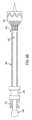
ここで図3を参照すると、様々な例において、導入器2300は、患者の脈管構造内の治療部位(又はその近位の位置)への塞栓フィルタシステムのデリバリーを容易にするように構成された長手方向に延在している構造である。具体的には、幾つかの例において、導入器2300は、長尺要素2100及びフィルタ2200を導入器上に装填し、患者の脈管構造内の治療部位にデリバリーすることができるように構成される。示されるように、例示の導入器2300は遠位端2302及び近位端2304を含む。幾つかの例において、中間部2306は、遠位端2302と近位端2304との間に位置する。幾つかの例において、導入器2300は長尺要素取り付け部2308及びフィルタ取り付け部2310を含む。幾つかの例において、中間部2306は長尺要素取り付け部2308及びフィルタ取り付け部2310を含む。3, in various examples, the
幾つかの例において、導入器2300は概して円筒形であるが、他のプロファイルも想定される。さらに、幾つかの例において、導入器2300は、限定するわけではないが、円形及び楕円形の断面を含む任意の適切な断面プロファイルを有することができる。幾つかの例において、導入器2300はその遠位端2302に鈍い先端を含む。幾つかの例において、近位端2304は概してテーパ型である先端を含む。例えば、図4A及び図4Bに示すように、導入器2300は、近位端2316よりも小さい断面を有する遠位端2314を有するテーパ型先端2312を含む。幾つかの例において、テーパ型先端2312の遠位端2314は導入器2300の遠位端2304に対応する。幾つかの例において、テーパ型先端2312は、フィルタ取り付け部2310から延在し、その遠位に配置される。In some examples, the
上述のように、導入器2300は、長尺要素2100及びフィルタ2200が患者の血液から塞栓性デブリをろ過するように動作できるように、長尺要素2100及びフィルタ2200の治療部位(又はそれに対して近位の位置)へのデリバリーを容易にするように構成されている。当業者は、その柔軟で追従性の性質のために、長尺要素2100は導入器2300の補助なしに脈管構造を通して容易に前進することができないことを理解するであろう。要するに、長尺要素2100が導入器2300に取り付けられていない場合に、長尺要素2100の近位端2104に遠位方向の力を加えても、長尺要素2100の遠位端を並進させることには、効果があったとしてもほとんどないであろう。このような状況下において、当業者は、長尺要素2100はその長手方向の長さに沿って座屈する(又はアコーディオン形状化する)であろうことを理解する。したがって、長尺要素2100などの柔軟で追従性の長尺要素の場合には、導入器2300を利用して、長尺要素(及びしたがってフィルタ2200)を患者の脈管構造を通して標的部位まで前進させる。As discussed above, the
幾つかの例において、導入器2300の長尺要素取り付け部2308は長尺要素2100をその上に取り付けることができるように長尺要素2100と相補的である(例えば、長さ、形状、断面積など)。幾つかの例において、長尺要素取り付け部2308は滑らかな連続面である。幾つかのこのような例において、導入器2300に取り付けられたときに、長尺要素2100は導入器2300の長尺要素取り付け部2308によって支持される。In some instances, the elongate
同様に、幾つかの例において、導入器2300のフィルタ取り付け部2310はフィルタ2200が半径方向に折り畳まれてデリバリー用に構成されているときに、フィルタ2200と相補的である(例えば、長さ、形状、断面積など)。幾つかの例において、フィルタ取り付け部2310は、導入器2300内のレリーフとして形成される。幾つかの例において、レリーフは、円周状のレリーフであるが、そうである必要はない。幾つかの例において、当業者に理解されるように、取り外し可能な拘束シースは少なくともフィルタ及び/又は長尺要素の周りに配置されて、フィルタ及び/又は長尺要素を導入器上でデリバリー構成に維持する。そのような例において、長尺要素及びフィルタを標的部位にデリバリーしたときに拘束シースを取り外すことができ、ここで、フィルタはその半径方向に拡張された展開構成に拡張することができる。様々な例において、取り外し可能な拘束シースは、スリーブ、シース、ソック又は他の拘束機構であることができる。当業者であれば、フィルタの展開は、近位から遠位、遠位から近位、端部から内部、中央から外部などで起こりうることを理解するであろう。Similarly, in some examples, the
幾つかの例において、フィルタ2200が半径方向に折り畳まれてその上に取り付けられると、半径方向に折り畳まれたフィルタ2200はレリーフ内に受け入れられる。例えば、レリーフは、半径方向に折り畳まれたフィルタが長尺要素取り付け部2308の周りに配置された(又は取り付けられた)長尺要素を超えて半径方向に突出しないように、フィルタのメンブレン及び/又は構造要素を収容するのに十分な半径方向の深さを有する。そのような構成は、最小のデリバリープロファイルを有するシステムを提供する。In some instances, when the
幾つかの例において、導入器に沿った長尺要素及びフィルタの位置は、半径方向に折り畳まれたフィルタが円周方向のレリーフ内に受け入れられる結果として、デリバリー中に維持される。具体的には、当業者に理解されるように、フィルタが半径方向に折り畳まれてフィルタ取り付け部によって受け入れられると、導入器に加えられた力はレリーフによってフィルタに伝達される。したがって、フィルタが半径方向に折り畳まれてフィルタ取り付け部によって受け入れられると、導入器の並進運動はフィルタに伝達され、それにより、フィルタ及び長尺要素は導入器と共に並進する。In some instances, the position of the elongate element and filter along the introducer is maintained during delivery as a result of the radially folded filter being received within the circumferential relief. Specifically, as will be appreciated by those skilled in the art, when the filter is radially folded and received by the filter mount, forces applied to the introducer are transferred to the filter by the relief. Thus, when the filter is radially folded and received by the filter mount, translational motion of the introducer is transferred to the filter, causing the filter and elongate element to translate with the introducer.
図4A~4Cは塞栓フィルタシステム2000を示す。図4Aはデリバリー構成で示されている例示の塞栓フィルタシステム2000の図である。上述のように、幾つかの例において、長尺要素2100及びフィルタ2200は導入器2300に取り付けられる。長尺要素2100及びフィルタ2200が取り付けられている導入器2300は、長尺要素2100及びフィルタ2200が患者の脈管構造内の標的部位へのデリバリーのために構成されるように拘束シース内に配置される。具体的には、図4Aに示されるように、フィルタ2200は半径方向に折り畳まれたデリバリー構成にある。上述のように、幾つかの例において、長尺要素2100及び/又はフィルタ2200は、フィルタ2200及び長尺要素2100の標的部位へのデリバリーを容易にするために、拘束部材2400に対して前進させることができる。幾つかの例において、長尺要素2100及び/又はフィルタ2200が前進されている間に、拘束要素2400は固定状態を保持する。幾つかの例において、上記で説明されたように、長尺要素2100及び/又はフィルタ2200は、フィルタ2200及び/又は長尺要素2100が取り付けられている導入器2300を前進させることによって前進される。Figures 4A-4C show
図4Bは、導入器2300を拘束要素2400に対して遠位方向に前進させた後の例示の塞栓フィルタシステム2000の図である。具体的には、示されるように、フィルタ2200が拘束要素2400の遠位端2402を超えて遠位方向に前進されるように、導入器2300は拘束要素2400に対して前進されている。したがって、フィルタ2200が、拘束要素2400の遠位端2402を超えて遠位方向に前進させられると、フィルタ2200は、その半径方向に拡張された展開構成まで自由に拡張する。しかし、幾つかの例において、追加の拘束シースの除去が必要とされうる。FIG. 4B is a diagram of the exemplary
幾つかの例において、フィルタ2200がその半径方向に拡張された展開構成に拡張された後に、導入器2300を引き出すことができる。すなわち、フィルタ2200がその半径方向に拡張された展開構成に拡張した後に、脈管構造内でフィルタ2200及び/又は長尺要素2100の位置を変位させることなく導入器2300を引き出すことができる。幾つかの例において、フィルタ2200がその半径方向に拡張された展開構成に拡張すると、フィルタ2200はフィルタ取り付け部に受け入れられず又はさもなければ取り付けられない(例えば、フィルタ2200はもはや円周レリーフ内に受け入れられない)。したがって、導入器が並進すると、導入器の機構(例えば、フィルタ取り付け部)は、長尺要素又はフィルタを導入器と並進させるのに十分なように長尺要素又はフィルタと係合することはない。In some instances, the
ここで図4Cを参照すると、導入器2300は長尺要素2100及びフィルタ2200から取り除かれている。幾つかの例において、導入器2300が取り除かれた状態で、塞栓フィルタシステム2000が展開されている脈管構造を通って流れる血液はフィルタ2200及び/又は長尺要素2100に流れ込む。幾つかの例において、この血流は、長尺要素2100を膨張させ又はさもなければ長尺要素2100がそれ自体の重さの下で潰されるのを防ぐのに十分である。すなわち、長尺要素2100が、さもなければそれ自体の重量を支えることができない柔軟で追従性の材料である例において、長尺要素2100中に流れ込む血液は、長尺要素2100を膨張させ又はさもなければ長尺要素2100が潰されるのを防止するのに十分な圧力を管腔の内側に加える。上述のように、長尺要素は1つ以上の血液透過性領域を含むことができる。同様に、図示されていないが、幾つかの例において、血液が長尺要素2100を通って灌流して脈管構造に再び入ることができるように、拘束要素2400を長尺要素2100の長さの一部(又は全部)に沿って引き込むことができる。幾つかの例において、拘束要素は1つ以上の血液透過性領域又は区域を含むことも理解されるであろう。4C, the
幾つかの例において、塞栓フィルタシステム2000は、上述のように止血シール部材2500を含む。一般に、止血シール部材は、止血シールを維持するように動作し、それを通して1つ以上のメディカルデバイスを、血液損失を最小限に抑えながら通過させることができる。止血シール部材の例は、2016年4月19日に交付された少なくとも米国特許第9,314,605号明細書、及び、米国特許第9,561,347号として2017年2月7日に交付されることを予定している米国特許出願第13/677,839号を有する米国特許出願公開第2013/0123705号明細書に見出すことができ、それぞれの全内容は参照により本明細書に取り込まれる。In some examples, the
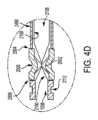
幾つかの例において、柔軟で追従性の長尺要素2100は止血シール部材2500と共に動作して止血シールを維持しながら、上記のように、1つ以上のメディカルデバイスを長尺要素2100の作業管腔を通して治療部位まで前進させることを可能にする。具体的には、図4Dを参照すると、止血シール部材2500及び長尺要素2100の断面図は示されている。示されるように、止血シール部材は1つ以上の加圧要素2502を含み、それは止血シール部材2500の内側に止血シールを形成するように動作する。幾つかの例において、止血シール部材2500のこれらの加圧要素2502は、柔軟で追従性の長尺要素2100が止血シール部材2500を通過するときにそれを潰すように動作する。これらの例において、中の血液によって長尺要素2100の内側に及ぼされる圧力は、止血シール部材2500を通して通過する領域において長尺要素2100の管腔2108を潰すように動作する加圧要素2502によって加えられる圧力に打ち勝つには不十分である。In some instances, the flexible, compliant
例えば、図4Dに示されるように、長尺要素2100の管腔2108は、その中の血液によって長尺要素2100の管腔2108の内側に及ぼされる圧力によって止血シール部材2500の遠位側2504上で膨張される。同様に、示されるように、長尺要素2100は、止血シール部材2500の近位側2506上で長尺要素2100の材料に結合された停止機構2112によって構造的に支持されている。For example, as shown in FIG. 4D, the
当業者は、メディカルデバイスが止血シール部材2500の近位側2506上の長尺要素2100の管腔2108に導入され、それを通して遠位側2504までそれを通して前進されるときに、加圧要素2502は、長尺要素2100に圧力を加え、長尺要素2100に、管腔2108の内部とそこを通って前進するメディカルデバイスとの間の止血シールを形成させることができる。Those skilled in the art will appreciate that when a medical device is introduced into the
したがって、柔軟で追従性の長尺要素2100は、止血シールが長尺要素2100の管腔2108によって形成されるように止血シール(上述の止血シールなど)により利用することができ、一方、1つ以上のメディカルデバイスが患者の体外の位置から治療部位まで通過させてデリバリーすることができる作業管腔として管腔2108を維持する。幾つかの例において、柔軟で追従性の長尺要素2100は、止血シールと長尺要素2100の外側表面との間及び長尺要素2100の管腔2108内(例えば、内側管腔を潰すことによって)の両方に止血シールが形成されるように、止血シールにより利用されることができる。Thus, the flexible, compliant
ここで図4Eを参照すると、長尺要素2100及びフィルタ2200の引き出しを示している。幾つかの例において、患者の脈管構造内の標的部位に柔軟で追従性の長尺要素2100及びフィルタ2200をデリバリーするときには、導入器2300を利用するが、長尺要素2100及びフィルタ220は、導入器2300を利用せずにそこから引き出され、又はさもなければ除去されうる。具体的には、幾つかの例において、長尺要素2100の近位端2104に引張力2600を加えて、長尺要素2100及びフィルタ2200を標的部位から引き出すことができる。上述したように、長尺要素2100は、柔軟で追従性であるにもかかわらず、当業者には理解されるように、標的部位からそのように引き出しを可能にするのに十分な引張強度を有する材料から構築されている。少なくとも幾つかの例において、幾つかの考えられる材料は1400~7000psiの引張強度特性に関連する。しかしながら、より高い及びより低い引張強度を有する他の材料も考えられる。4E, which illustrates the withdrawal of the
図4Eに示されるように、長尺要素2100及びフィルタ2200が引き出されると、フィルタ2200は、拘束要素2400内に引き込まれるにつれて半径方向に折り畳まれる。幾つかの例において、拘束要素2400は、フィルタ2200を半径方向に折り畳むのに十分に剛性である。幾つかの例において、長尺要素2100及びフィルタ2200によって捕捉された塞栓性デブリは、長尺要素2100及びフィルタ2200を脈管構造から除去する間に、長尺要素2100及びフィルタ2200内に保持されている。しかしながら、幾つかの例において、フィルタ2200及び長尺要素2100内に捕捉された塞栓性デブリは、引き出す前に追加的又は代替的に吸引することができる。そのような構成は、フィルタ2200及び長尺要素2100が引き出されるときに、捕捉された塞栓性デブリが脈管構造内に解放されて戻る可能性を最小限に抑えるのに役立つ。As shown in FIG. 4E, when the
幾つかの例において、長尺要素2100及びフィルタ2200は、フィルタ2200が止血シール部材2500を通過するように引き出すことができる。幾つかの例において、止血シール部材2500は拘束部材2400に結合されている。このように、幾つかの例において、長尺要素2100及びフィルタ2200は、拘束要素2400の引き出しとは独立して脈管構造から引き出すことができる。幾つかのそのような例において、止血シール部材2500は、長尺要素2100及びフィルタ2200が止血シール部材2500を通して引き出されるときに、塞栓フィルタシステム2000を通じた血液損失を最小限に抑えそして止血シールを維持するように動作する。In some instances, the
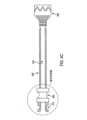
ここで図5Aを参照すると、塞栓フィルタシステム5000は大動脈弓5502内でのデリバリー構成で示されている。塞栓フィルタシステム5000は、本明細書に例示及び説明されている塞栓フィルタシステムのいずれかであってよい。図示されるように、塞栓フィルタシステム5000は患者の脈管構造を通って標的部位まで前進される。この例示された例において、塞栓フィルタシステム5000は上行大動脈5510又はその近傍で大動脈弓5502内のある位置まで前進される。幾つかの例において、塞栓フィルタシステム5000は、患者の脈管構造を通って前進されそして標的部位にデリバリーされるデリバリー構成にある。上記でより詳細に論じたように、デリバリー構成にあるとき、長尺要素及びフィルタは拘束要素5300などの拘束部材内に受け入れられる(又は少なくとも部分的に受け入れられる)。示されるように、幾つかの例において、塞栓フィルタシステム5000はガイドワイヤ5600に沿ってガイドされる。5A, the
幾つかの例において、塞栓フィルタシステムが標的部位まで前進した後に、フィルタ及び長尺要素は展開される。ここで図5Bを参照すると、塞栓フィルタシステム5000は大動脈弓5502において部分的に展開された状態で示されている。具体的には、拘束要素5300は、フィルタ5200の近位端に対して近位の位置まで部分的に引き出され、フィルタ5200はその展開形態に移行している。展開された構成において、図5Bに示すように、フィルタ5200の遠位端5202は、フィルタ5200が展開されている大動脈の部分の断面積と実質的に等しい断面積を有する。この図示の例において、フィルタ5200は、フィルタ5200が展開されている大動脈弓5502の領域の壁の一部又は全部に接触している。その結果、フィルタ5200は、上行大動脈5510から流れる血液をフィルタ5200に向けるように動作する。In some instances, after the embolic filter system has been advanced to the target site, the filter and elongate element are deployed. Referring now to FIG. 5B, the
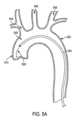
図5Cは拘束要素5300とともにフィルタ5200及び長尺要素5100を示し、拘束要素5300がそこから引き出されている(又は少なくとも大動脈弓5502の遠位の位置まで引き出されている)。幾つかの例において、フィルタ5200は血液透過性であるため、腕頭動脈5504、頸動脈5506及び鎖骨下動脈5508への血液の灌流、ならびに下行大動脈5512及び下流の脈管構造への大動脈弓5502を通じた灌流が可能である。さらに、長尺要素5100は血液透過性窓5150を含むものとして示されている。したがって、血液透過性窓5150から少なくとも鎖骨下動脈5508への血液の灌流が可能である。5C shows the
上述のように、塞栓フィルタシステムの透過性の程度はフィルタ及び/又は長尺要素の長さに沿って変化することができる。図5Cの例示されている例において、血液透過性窓5150は、フィルタが不透過性である粒子に対して透過性であるように構成されてもよい。したがって、フィルタ5200を透過しなかったより大きな粒子は血液透過性窓5150を透過することができる。上記に説明したように、このような結果を達成するための1つの方法は、第一の平均サイズを有する複数の第一の穿孔を有するフィルタを構成すること、及び、前記複数の第一の穿孔の平均サイズよりも大きい第二の平均サイズを有する複数の第二の穿孔を有する血液透過性窓を構成することを含む。特定の上述の例は、ある程度の血液透過性を有するフィルタ(例えば、1200)を含むが、幾つかの例において、フィルタは、フィルタが血液及び他の媒体(例えば、塞栓性デブリ)を長尺要素に送り込むデフレクタとして代わりに動作するように血液に対して不透過性であることができる。As discussed above, the degree of permeability of the embolic filter system can vary along the length of the filter and/or elongate element. In the illustrated example of FIG. 5C, the blood
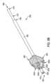
上述のように、幾つかの例において、長尺要素の遠位部分は、フィルタの近位端から遠位方向に延在していることができ、作業管腔として動作することができる。図5Dの図示されている例において、長尺要素5100の遠位部分5110は、フィルタ5200の近位端5204から遠位方向に延在している。図示のように、長尺要素5100の作業管腔5108は、治療部位への1つ以上のメディカルデバイス、例えばメディカルデバイス5700のデリバリーのための機構を提供する。図5Dの図示されている例において、遠位部分5110は、上述のように、メディカルデバイス5700とフィルタ5200との間の絡み合いを防止するように動作する。As discussed above, in some examples, the distal portion of the elongate element can extend distally from the proximal end of the filter and can act as a working lumen. In the illustrated example of FIG. 5D, the
上述のように、様々な例において、長尺要素及び/又はフィルタは、患者の血液から塞栓性デブリ及び他の血液媒体をろ過するように動作する。幾つかのそのような例において、長尺要素及び/又はフィルタは十分に透過性の材料から形成され、及び/又は、1つ以上の穿孔を含む。同様に、上述のように、幾つかの例において、長尺要素及び/又はフィルタは長尺要素及び/又はフィルタが1つ以上の区別される位置で透過性(例えば、血液透過性)であるように構成されている。幾つかの例において、長尺要素及び/又はフィルタは、幾つかの位置で血液透過性であり、他の位置で血液不透過性であるように構成することができる。幾つかの例において、長尺要素及び/又はフィルタは血液及び塞栓性デブリをさらにろ過するように構成された1つ以上のろ過窓を含む。As discussed above, in various examples, the elongate element and/or filter operates to filter embolic debris and other blood media from the patient's blood. In some such examples, the elongate element and/or filter is formed from a substantially permeable material and/or includes one or more perforations. Similarly, as discussed above, in some examples, the elongate element and/or filter is configured such that the elongate element and/or filter is permeable (e.g., blood permeable) at one or more distinct locations. In some examples, the elongate element and/or filter can be configured to be blood permeable at some locations and blood impermeable at other locations. In some examples, the elongate element and/or filter includes one or more filtering windows configured to further filter blood and embolic debris.
一般に、透過性窓(例えば、血液透過性)は、長尺要素又はフィルタに沿って又はその周りのどこにでも配置することができ、様々な適切な寸法(限定するわけではないが、円形、卵形、細長、らせん、ランダムなどを含む)を備えることができる。幾つかの例において、長尺要素又はフィルタは、長尺要素又はフィルタの隣接部分よりも大きい多孔度を有する少なくとも1つの窓を備えることができる。In general, the permeable windows (e.g., blood permeable) can be located anywhere along or around the elongate element or filter and can have a variety of suitable dimensions (including, but not limited to, circular, oval, elongated, spiral, random, etc.). In some examples, the elongate element or filter can have at least one window having a greater porosity than an adjacent portion of the elongate element or filter.
様々な例において、1つ以上の透過性窓(例えば、血液透過性)を使用して、長尺要素又はフィルタ内の停滞した血液列の可能性を低減又は排除することができる。例えば、幾つかの例において、停滞しているトラップされた塞栓性デブリは多孔度を減少させ、長尺要素又はフィルタにわたる圧力勾配を増加させる可能性がある。その結果、停滞している塞栓性デブリは、時間がたつにつれて蓄積しそしてろ過効率を低下させる可能性があり、これは特に問題となる可能性がある。他方で、1つ以上の透過性窓(例えば、血液透過性)を有する長尺要素は、血液及び方向変換された塞栓性デブリがその管腔中に移行させることを可能にしうる。ここで、その収集はろ過効率に悪影響を及ぼさず、吸引によるその除去はオペレータにより行うことができる。In various examples, one or more transparency windows (e.g., blood permeable) can be used to reduce or eliminate the possibility of stagnant blood columns within the elongate element or filter. For example, in some examples, stagnant trapped embolic debris can reduce porosity and increase pressure gradients across the elongate element or filter. As a result, stagnant embolic debris can accumulate over time and reduce filtration efficiency, which can be particularly problematic. On the other hand, an elongate element with one or more transparency windows (e.g., blood permeable) can allow blood and redirected embolic debris to migrate into its lumen, where collection does not adversely affect filtration efficiency and removal by suction can be performed by the operator.
様々な例において、透過性窓は、それを通る血液の灌流を可能にしながら、吸引処置などの間に血液が入るのを防ぐための一方向フラップ又はバルブを含むことができる。幾つかの例において、一方向バルブは、1つ以上のスリットを有し、一方向に開くようにバイアスされている生体適合性材料(例えば、フルオロポリマー)を含むことができる。幾つかの例において、一方向フラップは、支持フレームを有する生体適合性材料(例えば、フルオロポリマー)を含むことができる。幾つかの例において、窓を実質的に覆うように、一方向フラップ又はバルブを透過性窓(例えば、血液透過性)の外面及び/又は内面に配置することができる。In various examples, the transmissive window can include a one-way flap or valve to prevent blood from entering during aspiration procedures, etc., while allowing blood perfusion therethrough. In some examples, the one-way valve can include a biocompatible material (e.g., a fluoropolymer) having one or more slits and biased to open in one direction. In some examples, the one-way flap can include a biocompatible material (e.g., a fluoropolymer) having a support frame. In some examples, the one-way flap or valve can be disposed on an exterior and/or interior surface of the transmissive window (e.g., blood permeable) to substantially cover the window.
上述のように、様々な例において、フィルタは構造要素を含む。様々な例において、構造要素は、1つ以上の編組、メッシュ、格子、ワイヤ、リング、スタット又は任意の他の適切な支持要素などの1つ以上の支持要素を含む。幾つかの例において、支持要素はチューブ状であり、そしてレーザ切断され又は別々に形成されることができる。幾つかの例において、当業者に理解されるように、構造要素が自己拡張性構造要素であるように、1つ以上の支持要素をニチノールなどの形状記憶材料から形成することができる。しかしながら、他の例において、1つ以上の支持要素は、膨張助材(バルーンなど)の使用を通して膨張可能であることができる他の弾性金属から形成することができる。例えば、1つ以上の支持要素は、ポリマー又はステンレス鋼などの生体適合性金属合金から形成されてもよい。As discussed above, in various examples, the filter includes a structural element. In various examples, the structural element includes one or more support elements, such as one or more braids, meshes, lattices, wires, rings, studs, or any other suitable support elements. In some examples, the support elements are tubular and can be laser cut or separately formed. In some examples, the one or more support elements can be formed from a shape memory material, such as Nitinol, such that the structural elements are self-expanding structural elements, as will be appreciated by those skilled in the art. However, in other examples, the one or more support elements can be formed from other elastic metals that can be expandable through the use of an expansion aid (such as a balloon). For example, the one or more support elements may be formed from a polymer or a biocompatible metal alloy, such as stainless steel.
さらに、当業者であれば、本明細書で論じた構成は、異なる用途に合わせて拡大又は縮小できるという点でスケール化可能であることを理解するであろう。すなわち、本明細書で論じる特定の構成は大動脈弓内の配置に関連して図示及び説明しているが、システムの多用途性は患者の脈管構造の実質的に他のあらゆる領域での実施を可能にする。例えば、本明細書で論じる様々な構成は、腕頭動脈及び/又は頸動脈及び/又は鎖骨下動脈などの様々な末梢血管及び管腔内での用途に合わせて拡大縮小調整することができる。同様に、その構成が大動脈弓に関するときに、本開示は、大腿、経心尖及び開胸アプローチに関連して使用され得る。さらに、本開示は用途を心臓に近い脈管に限定するものとして解釈されるべきではない。例えば、本明細書に記載されているデバイス及びシステムは、心臓の上及び下の脈管構造を含む身体の脈管構造全体にわたって実施されて、他の様々な脈管再生処置中の塞栓性デブリの移行を防止することができる。さらに、実施形態は、ヒトだけでなく、哺乳動物の解剖学的構造を有する様々な生物に関しても使用することができる。したがって、本明細書に記載の実施形態は、本開示の範囲内の変更形態及び変形形態を網羅することを意図している。Furthermore, one skilled in the art will appreciate that the configurations discussed herein are scalable in that they can be expanded or contracted for different applications. That is, while the particular configurations discussed herein are shown and described in relation to placement within the aortic arch, the versatility of the system allows for implementation in virtually any other area of the patient's vasculature. For example, the various configurations discussed herein can be scaled for application in various peripheral vessels and lumens, such as the brachiocephalic and/or carotid and/or subclavian arteries. Similarly, as the configurations relate to the aortic arch, the present disclosure can be used in relation to femoral, transapical and open chest approaches. Furthermore, the present disclosure should not be construed as limiting the application to vessels close to the heart. For example, the devices and systems described herein can be implemented throughout the vasculature of the body, including the vasculature above and below the heart, to prevent migration of embolic debris during various other revascularization procedures. Furthermore, the embodiments can be used in relation to various organisms having mammalian anatomy as well as humans. Thus, the embodiments described herein are intended to cover modifications and variations within the scope of the present disclosure.
加えて、幾つかの例において、所与の処置のために複数のデバイス又はシステムを展開することができる。例えば、幾つかの心臓手術において、本明細書に記載のデバイスの1つを大動脈弓及び/又は腕頭動脈及び/又は頸動脈及び/又は鎖骨下動脈に配置することができる。Additionally, in some instances, multiple devices or systems may be deployed for a given procedure. For example, in some cardiac procedures, one of the devices described herein may be placed in the aortic arch and/or the brachiocephalic and/or carotid and/or subclavian arteries.
ここで図6A及び図6Bを参照すると、塞栓フィルタシステム6000は示されている。様々な例において、塞栓フィルタシステム6000は、第一の長尺要素6100、フィルタ部分6200及び第二の長尺要素6300を含む。図示されるように、塞栓フィルタシステム6000は遠位端6002及び近位端6004を含む。同様に、幾つかの例において、第一の長尺要素6100は遠位端6102(第二の長尺要素6300の遠位端によって視界から遮られている)及び近位端6104を含み、第二の長尺要素6300は遠位端6302及び近位端6304を含む。様々な例において、第一の長尺要素及び第二の長尺要素のそれぞれは、それを通って延在している管腔を有する。例えば、第一の長尺要素は内側管腔6106を含み、第二の長尺要素は、内側管腔6306を含む(視界から遮られている)。幾つかの例において、第一の長尺要素の内側管腔6106は、本明細書に記載されるように作業管腔として動作する。6A and 6B, an
幾つかの例において、第一の長尺要素6100は、第一の長尺要素6100と第二の長尺要素6300とが同軸であるように、第二の長尺要素6300の内側管腔内に配置されている。図6A及び図6Bに示すように、第一の長尺要素6100は、第二の長尺要素6300の遠位端と近位端との間に延在している。幾つかの例において、第一の長尺要素6100の遠位端6102は第二の長尺要素の遠位端と位置合わせされている。In some instances, the first
幾つかの例において、第二の長尺要素6300は、上述のように、それを通って延在している管腔を有する長手方向に延在している構造である。幾つかの例において、第二の長尺要素6300は、支持要素6202A、6202B、6202C、6202D、6202E及び6202F(視界から遮られている)などの1つ以上の支持要素を含む展開可能なフィルタ部分6200を含む。一般に、支持要素は、第二の長尺要素6300の周りに均等に分布している。幾つかの例において、支持要素は、第二の長尺要素6300の壁に形成されている。幾つかのそのような例において、1つ以上のスリット又は切断線は第二の長尺要素6300の壁に形成されている。スリット又は切断線は、第二の長尺要素6300の一部に沿って長手方向に延在している。支持要素は、隣接する長手方向に延在しているスリットの間に形成されている。一般に、スリットは、第二の長尺要素6300の外側表面から内側管腔まで貫通している。In some examples, the second
幾つかの例において、支持要素は、図示のように、第二の長尺要素6300の遠位端6302の近位の位置からそれに対して近位方向のある位置まで延在している。すなわち、各支持要素は、遠位端、近位端及びそれらの間に延在している中間部を有する。幾つかの例において、支持要素の長さは、支持要素の遠位端と近位端との間での測定値である。幾つかの例において、支持要素の遠位端及び近位端は、以下でさらに説明されるように、第二の長尺要素6300中を終端とする。In some instances, the support elements extend from a location proximal to the
幾つかの例において、血液透過性メンブレン6204(上述のメンブレンなど)が支持要素又はその一部の周囲に配置されている。幾つかの例において、血液透過性メンブレンの遠位端は支持要素の中間部に沿って配置されている。幾つかの例において、血液透過性メンブレンの近位端は、支持要素の近位端又はそれに対して近位に配置されている。すなわち、幾つかの例において、血液透過性メンブレンは、支持要素の遠位端に対して近位にある支持要素に沿った位置から支持要素の近位端又はその近位まで延在している。幾つかの例において、以下でさらに説明されるように、支持要素及び血液透過性メンブレンは、血液から塞栓性デブリをろ過するように動作する。In some instances, a blood permeable membrane 6204 (such as the membranes described above) is disposed around the support element or a portion thereof. In some instances, the distal end of the blood permeable membrane is disposed along an intermediate portion of the support element. In some instances, the proximal end of the blood permeable membrane is disposed at or proximal to the proximal end of the support element. That is, in some instances, the blood permeable membrane extends from a location along the support element proximal to the distal end of the support element to or proximal to the proximal end of the support element. In some instances, the support element and blood permeable membrane operate to filter embolic debris from the blood, as described further below.
幾つかの例において、血液透過性メンブレンは、支持要素の近位端又はそれに対して近位で長尺要素に結合されるか又はさもなければ固定される。幾つかの例において、血液透過性メンブレンは、支持要素の中間部にさらに結合されるか又はさもなければ固定されるが、そうである必要はない。幾つかの他の例において、血液透過性メンブレンは、血液透過性メンブレンの遠位端から支持要素又はその遠位にある第二の長尺要素6300の一部のいずれかに沿った位置まで延在している1つ以上のテザーを含む。例えば、図6A及び図6Bに示すように、第二の長尺要素6300は、長尺要素の遠位端6302と支持要素の遠位端との間に延在している遠位部分6308を含む。幾つかの例において、支持要素は、遠位部分6308がスリットを含まないように、遠位部分6308の近位を終端とする。In some examples, the blood permeable membrane is bonded or otherwise secured to the elongate element at or proximal to the proximal end of the support element. In some examples, the blood permeable membrane is further bonded or otherwise secured to an intermediate portion of the support element, but need not be. In some other examples, the blood permeable membrane includes one or more tethers extending from the distal end of the blood permeable membrane to a location along either the support element or a portion of the second
幾つかの例において、第一の長尺要素6100及び第二の長尺要素6300は、遠位部分6308で互いに固定されるか又はさもなければ互いに結合されている。幾つかの例において、第一の長尺要素6100及び第二の長尺要素6300はそれらの遠位端が相対的な軸方向の並進に対して拘束されるように一緒に固定され又はさもなければ結合されている。幾つかのそのような例において、遠位部分6308に対して近位にある第一の長尺要素6100及び第二の長尺要素6300の部分は、互いに対して自由に軸方向に並進(又は摺動)することができる。以下でさらに説明されるように、塞栓フィルタシステム6000のろ過部分は、第一の長尺要素6100の近位端6104に対して第二の長尺要素6300の近位端6304を摺動させることによって展開される。In some instances, the first
様々な例において、塞栓フィルタシステム6000は患者の脈管構造の領域内で展開されることができ、それにより、塞栓フィルタシステム6000はその領域を通って流れる血液から塞栓性デブリをろ過するように動作する。幾つかのそのような例において、塞栓フィルタシステム6000は、以下でさらに詳細に説明されるように、展開構成とデリバリー構成との間で移行可能である。図6Aは、デリバリー構成にある塞栓フィルタシステム6000を示し、一方、図6Bは、展開構成にある塞栓フィルタシステム6000を示す。様々な例で。In various examples, the
幾つかの例において、デリバリー構成において、塞栓フィルタシステム6000は最小デリバリープロファイルを維持する。しかしながら、展開構成に移行すると、塞栓フィルタシステム6000のろ過部分は、展開されている脈管の断面積の一部又は全部を占めるように拡張する(本明細書に記載の他の塞栓フィルタシステムと同様)。幾つかの例において、展開構成において、支持要素(6202A~6202F)又はその一部は第二の長尺要素6300の長手方向軸から離れるように撓む。In some instances, in the delivery configuration, the
幾つかの例において、塞栓フィルタシステム6000は、第一の長尺要素6100の近位端6104に対して第二の長尺要素6300の近位端6304を遠位方向で軸方向に並進又は摺動させることによって展開構成に移行する。幾つかの例において、塞栓フィルタシステム6000は、追加的に又は代替的に、第二の長尺要素6300の近位端6304に対して第一の長尺要素6100の近位端6104を近位方向で軸方向に並進又は摺動させることによって展開構成に移行する。幾つかの例において、塞栓フィルタシステム6000は、第二の長尺要素6300の近位端6304の一定の(又は実質的に一定の)位置を維持しながら、第一の長尺要素6100の近位端6104を近位に並進又は摺動させることによって同様に展開可能であることが理解されるであろう。同様に、幾つかの例において、塞栓フィルタシステム6000は、第一の長尺要素6100の近位端6104の一定の(又は実質的に一定の)位置を維持しながら、第二の長尺要素6300の近位端6304を遠位方向に並進又は摺動させることによって展開可能である。In some instances, the
第一の長尺要素6100及び第二の長尺要素6300は遠位部分6308で一緒に固定されているので、第二の長尺要素6300の近位端6304が第一の長尺要素6100の近位端6104に対して遠位に並進するときに、第一の長尺要素6100及び第二の長尺要素6300の1つ以上は座屈しなければならないことを当業者は理解するであろう。これに関して、第二の長尺要素6300の支持要素は、第二の長尺要素6300の長手方向軸から離れるように撓むように構成されている。例えば、図6Bに示されるように、支持要素(6202A~6202F)は、第二の長尺要素6300の近位端6304が第一の長尺要素6100の近位端6104に対して遠位に並進することの結果として、曲がる、座屈又は他の形で撓む。One skilled in the art will appreciate that because the first
支持要素のこの撓みは、塞栓フィルタシステム6000が展開されている脈管内で血液透過性メンブレン6204を拡張するように作用する。図6Bでは視界が遮られているが、幾つかの例において、第二の長尺要素6300の支持要素の下に延在している第一の長尺要素6100の部分は、脈管構造から取り外されるときに、塞栓フィルタシステム6000が展開形態からデリバリー形態に移行するときに、血液透過性メンブレンによって捕捉された塞栓性デブリを第一の長尺要素6100の管腔6106中に移行させることを可能にするように動作する1つ以上のアパチャ(アパチャ1112と同様)を含むことができる。幾つかの例において、そのようなアパチャは、塞栓フィルタシステム6000が展開構成にあるときに、血液透過性メンブレン6204の遠位端の位置に対して近位にある第一の長尺要素に沿って配置されている。このような構成は、管腔6106から逃げる塞栓性デブリが血液透過性メンブレン6204によって捕捉されそして保持されることを確保する。This deflection of the support element acts to expand the blood
第一の長尺要素が第二の長尺要素6300の支持要素の下に延在している第一の長尺要素6100の部分にアパチャがない他の幾つかの例において、血液透過性メンブレン6204によって捕獲された塞栓性デブリは、当業者に理解されるように、血液透過性メンブレン(及び/又は支持要素)と、第二の長尺要素6300の支持要素の下に延在している第一の長尺要素6100の部分の外側との間にトラップされる。In some other examples where there is no aperture in the portion of the first
幾つかの例において、塞栓フィルタシステム6000は、第一の長尺要素6100の近位端6104に対して第二の長尺要素6300の近位端6304を近位方向で軸方向に並進又は摺動させることによって、展開構成からデリバリー構成に移行される。幾つかの例において、塞栓フィルタシステム6000は、追加的又は代替的に、第二の長尺要素6300の近位端6304に対して第一の長尺要素6100の近位端6104を遠位方向で軸方向に並進又は摺動させることによって展開構成からデリバリー構成に移行される。幾つかの例において、第二の長尺要素6300の近位端6304の一定の(又は実質的に一定の)位置を維持しながら、第一の長尺要素6100の近位端6104を近位方向に軸方向に並進させることができることは理解されるであろう。同様に、幾つかの例において、第一の長尺要素6100の近位端6104の一定の(又は実質的に一定の)位置を維持しながら、第二の長尺要素6300の近位端6304を遠位方向で軸方向に並進させることができる。In some instances, the
塞栓フィルタシステム6000は6つの支持要素(6202A~6202F)を含むように図示及び記載されているが、塞栓フィルタシステム6000は任意の数の支持要素を含んでよいことは理解されるべきである。同様に、支持要素は、第二の長尺要素6300の周りに均等に分布しているように図示されているが、支持要素は不均衡に分布していることは理解されるべきである。同様に、支持要素は全て同じサイズ(長さ及び/又は幅)である必要はない。Although the
上述のように、幾つかの例において、システムは1つ以上のステアリングライン(又はワイヤ)を含むことができる。したがって、幾つかの例において、システムは操縦可能である。幾つかの例において、1つ以上のステアリングラインは長尺要素の遠位端に結合されている。図1Bを参照すると、幾つかの例において、1つ以上のステアリングラインは、長尺要素1100の遠位部分1110に結合されることができ、又は、代替的又は追加的に、長尺要素の遠位端1102に結合されることができる。したがって、幾つかの例において、1つ以上のステアリングラインは、フィルタの近位端の遠位のある位置(フィルタ1200の近位端1204など)で長尺要素に結合される。そのような構成はシステムの遠位端の操縦能力又は偏向性を向上させ、そのことは、脈管構造の蛇行領域をナビゲートするときの制御性を高め、脈管を損傷する危険性を最小限に抑えるのに役立つ。As mentioned above, in some examples, the system can include one or more steering lines (or wires). Thus, in some examples, the system is steerable. In some examples, the one or more steering lines are coupled to the distal end of the elongate element. With reference to FIG. 1B, in some examples, the one or more steering lines can be coupled to the
幾つかの例において、長尺要素及び/又はデフレクタは、スリーブ、シース、ソック又は他の拘束機構内に収容することができる。そのような拘束機構(及び/又は長尺要素及び/又はデフレクタ自体)は、ロックされている場合には(例えば、ピン、ワイヤ又は他のもの)、(ステアリングラインとして動作する)張力ラインとして作用する展開ラインを有することができ、それにより、長尺要素及び/又はデフレクタを曲げることができる。幾つかのそのような例において、長尺要素が収容されているスリーブ、シース、ソック又は他の拘束機構は、一般に、ステアリングライン(すなわち、固定展開ライン又は張力ライン)が長尺要素に結合される領域の近位を終端とする。そのような構成は、張力がステアリングラインに加えられたときに長尺要素及びステアリングラインがバウアンドストリング(弓及び紐)構成を形成することができ、それでシステムの遠位端を偏向させることを提供する。当業者は、操縦可能な実施形態が大動脈弓又は他の蛇行脈管構造を治療するのに特に有益であり得ることを理解するであろう。操縦可能な実施形態は、蛇行した解剖学的構造において、デフレクタが屈曲部の外側に対して圧縮するのを防ぐのに特に有用であることができる。そのような操縦可能な実施形態はまた、脈管の軸及びデフレクタ機構の軸と実質的に位置合わせされている長尺要素からの出口を作り出すのにも有用であることができる。In some examples, the elongate elements and/or deflectors can be housed within a sleeve, sheath, sock, or other restraining mechanism. Such restraining mechanisms (and/or the elongate elements and/or deflectors themselves) can have deployment lines that, when locked (e.g., pins, wires, or other), act as tension lines (acting as steering lines), thereby bending the elongate elements and/or deflectors. In some such examples, the sleeve, sheath, sock, or other restraining mechanism in which the elongate elements are housed generally terminates proximal to the region where the steering lines (i.e., fixed deployment lines or tension lines) are coupled to the elongate elements. Such a configuration provides that the elongate elements and steering lines can form a bow-and-string configuration when tension is applied to the steering lines, thus deflecting the distal end of the system. Those skilled in the art will appreciate that steerable embodiments can be particularly beneficial for treating the aortic arch or other tortuous vasculature. Steerable embodiments can be particularly useful in tortuous anatomies to prevent the deflector from compressing against the outside of a bend. Such steerable embodiments can also be useful to create an exit from the elongate element that is substantially aligned with the axis of the vessel and the axis of the deflector mechanism.
幾つかの例において、塞栓フィルタシステム1000は、塞栓フィルタシステム1000を展開構成とデリバリー/取り外し構成との間で移行させるのを補助するように動作する1つ以上の機構を含む。同じではないが、幾つかの例において、そのような機構は、拘束要素1300に加えて又はそれに代わるものとして実装されてもよい。例えば、図7に示されるように、幾つかの例において、塞栓フィルタシステム1000は、拘束ファイバ1214などの1つ以上の拘束要素を含む。拘束ファイバ1214は、一般に、フィルタ1200の拡張及び/又は折り畳みを制御するように動作可能である。様々な例において、拘束ファイバ1214はフィルタ1200の周囲に引き回し、それにより、フィルタ1200の周囲に延在している拘束ファイバ1214の長さを減少及び/又は増大させてフィルタ1200を拘束又は拘束解除し、それによって、当業者が理解するように、フィルタを折り畳み状態と拡張状態との間で移行させることができる。In some examples, the
図7に示すように、拘束ファイバ1214はフィルタ1200の外側表面の周りに円周方向に引き回される。しかしながら、拘束ファイバ1214は、代替的にフィルタ1200の内側表面の周りに引き回されることができ、又は、フィルタ1200の内側表面及び外側表面の両方の1つ以上の部分に沿って横断するように引き回されることができることは理解されるであろう。例えば、幾つかの例において、フィルタ1200は、フィルタ1200の円周の周りに配置された複数の穿孔を含むことができる。幾つかのそのような例において、当業者に理解されるように、拘束ファイバ1214がフィルタ1200の周りに円周状に延在するように、拘束ファイバ1214は様々な穿孔を通って引き回される。拘束ファイバ1214は、上述の構成のいずれにおいても構造支持体1212の外側の周りに延在することができる。あるいは、幾つかの例において、拘束ファイバ1214は構造支持体1212の内側の周りに延在している。なおもさらに幾つかの例において、拘束ファイバ1214は構造支持体1212の内部及び外部の両方の1つ以上の部分の周りに延在するように引き回されることができる。As shown in FIG. 7, the constraining
幾つかの例において、拘束ファイバ1214は、フィルタ1200に沿って及び/又はフィルタ1200の周りに指定経路を画定するフィルタ1200の1つ以上の機構を通って引き回される。例えば、図7に示すように、塞栓フィルタシステム1000は、塞栓フィルタシステム1000の1つ以上の部分に沿って延在している1つ以上の引き回し導管1218を含む。幾つかの例において、1つ以上の引き回し導管1218は拘束要素1300の内側及び/又は外側に沿って延在している。幾つかの例において、1つ以上の引き回し導管1218は、上記の説明と一貫するフィルタ1200の内側及び/又は外側に沿って延在している。様々な例において、拘束ファイバ1214は、そのような引き回し導管1218を通って引き回され、それに対して摺動関係にある。したがって、引き回し導管1218は一般に拘束ファイバ1214の引き回し経路を束縛している間に、拘束ファイバ1214はそのような引き回し導管1218内で(例えば、それに対して)自由に摺動しないことが理解されるであろう。引き回し導管1218がフィルタ1200に沿って長手方向に延在しているように図7に示されているが、様々な例において、1つ以上の引き回し導管はフィルタ1200の周りで円周方向に(部分的又は全体的に)延在することができる。In some instances, the restraining
様々な例において、拘束ファイバ1214は、塞栓フィルタシステム1000の近位端から、例えばハンドル1400又は当業者に理解されるような他の制御機構から、長手方向に延在している。図7に示すように、拘束ファイバ1214は塞栓フィルタシステム1000の内部領域を通り、アパチャ1308を通り、フィルタ1200の外側表面に沿って延在している。幾つかの例において、拘束ファイバ1214は長尺要素1100の内側管腔の1つ以上の部分を通って延在している。幾つかの例において、拘束ファイバは、代替的に又は追加的に、拘束要素1300の内側管腔の1つ以上の部分を通って延在している。したがって、幾つかの例において、拘束ファイバ1214は、拘束要素1300と長尺要素1100との間に画定される環状領域内に延在している。さらに、拘束ファイバ1214は、拘束要素1300のアパチャ1308を通って延在するように示されているが、幾つかの例において、拘束ファイバ1214は、拘束要素1300の遠位端1302から(あるいは、長尺要素1100の遠位端1102から)延在している。In various examples, the restraining
様々な例において、当業者に理解されるように、拘束ファイバ1214はフィルタ1200の周囲にループを形成し、それにより、フィルタ1200を拘束し及び/又は拘束を解くようにループの直径を縮小又は拡大することができる。幾つかの例において、拘束ファイバ1214の遠位端は、拘束ファイバ1214に加えられる張力を変化させて結果としてループの直径の変動を引き起こすことができるように、拘束ファイバ1214をそれ自体で絡ませることを容易にするアイレット1216又は他の機構を含む。幾つかの例において、拘束ファイバ1214はロックワイヤと組み合わせて使用することができる。例えば、幾つかの例において、遠位端アイレットなどの拘束ファイバ1214の一部は、ロックワイヤとの係合によって拘束されている。ロックワイヤとのそのような係合は、拘束ファイバ1214をフィルタ1200の周りでその位置から取り除くことなく、拘束ファイバ1214から張力をかけそして張力を取り除くことを可能にする。幾つかのそのような例において、拘束ファイバ1214はフィルタ1200の周りに延在し、それ自体に絡み、ロックワイヤと係合する位置まで延在している。幾つかの例において、ロックワイヤを取り除くと、拘束ファイバ1214はロックワイヤから外され、フィルタ1200の周りから取り除かれることができる。In various examples, as will be appreciated by those skilled in the art, the constraining
上述のように、幾つかの例において、長尺要素2100は、それ自体の重量を支えるのに十分な構造的剛性を欠き、柱強度をほとんど又は全く有せず、及び/又は、一般にトルクをかけられないが、なお良好な引張強度を示す。幾つかの他の例において、長尺要素2100は、長尺要素2100が導入シース及び/又は拘束要素2400などの拘束要素内で前進可能であるように十分な構造的一体性を与える1つ以上の構造要素又は部品を含むことができる。すなわち、幾つかの例において、長尺要素は構造要素と被覆材料の両方を含む。構造要素及び被覆材料は本明細書で論じられたものと一貫している。長尺要素2100に構造要素を設けることによって、長尺要素2100は、導入器を追加する必要なしに脈管構造に導入することができる。特に、被覆材料と組み合わせた長尺要素2100の構造要素は、導入器シース及び/又は拘束シース内で前進させることができる(例えば、押すことができる)構築物を提供する。すなわち、長尺要素2100の近位端に遠位方向の力を加えることで、塞栓フィルタシステム2000が導入器に取り付けられていなくても、長尺要素2100(及びフィルタ2200)を遠位方向に並進させるように動作することになる。As discussed above, in some instances, the
幾つかの例において、そのような構成は従来の設計と比較して小さいデリバリープロファイルを有するシステムを提供する。というのは、幾つかの例において、当業者が理解するように、長尺要素2100は、導入器又はデリバリーカテーテル上に圧縮される代わりにそれ自体の上で半径方向に潰されることができるからである。同様に、導入器シース内及び/又は拘束シース内で押し込み可能であることによって、長尺要素2100はデリバリーのための追加の構成要素を必要とせず、これはシステムコスト、処置時間及び患者に対するリスクを低減する。In some instances, such a configuration provides a system with a smaller delivery profile compared to conventional designs because, in some instances, the
図8を参照すると、幾つかのそのような例において、塞栓フィルタシステム2000は、編組要素などの構造要素を有する長尺要素2100を含む。幾つかの例において、編組要素はニチノールワイヤを含むが、本明細書で論じられるものを含む他の材料も考えられる。幾つかの例において、編組要素は、ePTFE又は本明細書で論じる他の任意の適切な材料などの適切な被覆材料(例えば、フィルタ材料)で被覆されて、長尺要素2100を形成する。幾つかの例において、長尺要素2100の被覆材料は血液透過性である。他の例において、長尺要素2100の被覆材料は血液不透過性である。幾つかの例において、長尺要素の血液不透過性被覆材料は、血液が穿孔を通って流れるように動作可能であるように、本明細書の議論と一貫して変更される。幾つかのそのような例において、穿孔は、指定された閾値サイズを超える塞栓性デブリの通過を防ぐようにサイズ決めされる。例えば、本明細書で述べたように、穿孔は特定の用途に応じて50ミクロン~1000ミクロンであることができる。当業者が理解するように、長尺部材は、血液が長尺部材2100の1つ以上の部分を通って通過又は流れ、一方、長尺部材2100の1つ以上の他の部分を通って流れるのを防止するように動作可能であるように構成されうることも理解されるであろう。8, in some such examples, the
さらに、図8に示されるように、塞栓フィルタシステム2000はフィルタ2200を含む。フィルタ2200は、一般に、編組構造支持体2212及び被覆材料を含み、それは上記の議論と一貫する。幾つかの例において、フィルタ2200の被覆材料は長尺要素2100の被覆材料と同じである。幾つかの例において、フィルタ2200の構造支持体は長尺要素の構造支持体と同じである。幾つかの例において、フィルタ2200の被覆材料は血液透過性である。他の例において、フィルタ2200の被覆材料は血液不透過性である。幾つかの例において、フィルタ2200の血液不透過性被覆材料は、血液が穿孔を通って流れるように動作可能であるように、本明細書の議論と一貫して変更される。幾つかのそのような例において、穿孔は、本明細書で論じられるように指定された閾値サイズを超えた塞栓性デブリの通過を防ぐようにサイズ決めされる。当業者が理解するように、長尺部材は、血液がフィルタ2200の1つ以上の部分を通って通過又は流れ、一方、フィルタ2200の1つ以上の他の部分を通って流れるのを防止するように動作可能であるように構成されうることも理解されるであろう。8, the
デバイス及び/又は方法の構造及び機能の詳細と共に様々な代替形態を含む、多数の特徴及び利点は前述の記載において示されてきた。さらに、本開示において扱われる様々な概念の発明の範囲は、概略的にも特定の例に関しても記載されてきた。本開示は例示としてのみ意図されており、したがって網羅的であることが意図されていない。例えば、本開示の様々な実施形態は医療用途に関連して説明されているが、非医療用途においても有用でありうる。添付の特許請求の範囲が表現される用語の広く一般的な意味によって示される全範囲まで、特に構造、材料、要素、構成要素、形状、大きさ、及び本発明の原理内の組み合わせを含む部品の配置に関して、様々な変更が可能であることは当業者に明らかであろう。これらの様々な変更が添付の特許請求の範囲の主旨及び範囲から逸脱しない限り、これらの変更はその中に包含されることが意図される。
(態様1)
近位端及び遠位端を有する長尺要素と、
前記長尺要素の遠位端に配置されているフィルタ部分と、
を含む、塞栓フィルタであって、
ここで、前記長尺要素は第一の構造要素及び第一の被覆材料を含み、前記長尺要素はデリバリーシース内で前進されることを支持するために十分な構造的一体性を有し、及び、
前記フィルタ部分は第二の構造要素及び第二の被覆材料を含み、前記第二の被覆材料の一部は前記フィルタ部分に流入する血液から塞栓性デブリをろ過するように構成された複数の穿孔を含む、
塞栓フィルタ。
(態様2)
前記第一の構造要素は自己拡張型ワイヤブレイドである、態様1記載の塞栓フィルタ。
(態様3)
前記長尺要素の近位端に加えられる遠位方向の力は、デリバリーシースに対する長尺要素及びフィルタ部分の遠位方向の並進を引き起こすように動作可能である、態様1又は2記載の塞栓フィルタ。
(態様4)
前記長尺要素は、導入器を必要とせずにデリバリーシース内で前進されるのを支持するのに十分な構造的一体性を有する、態様1~3のいずれか1項記載の塞栓フィルタ。
(態様5)
前記フィルタ部分は血液透過性であり、前記複数の穿孔は100ミクロンの平均サイズを有する、態様1~4のいずれか1項記載の塞栓フィルタ。
(態様6)
前記フィルタ部分の第二の被覆材料は血液不透過性であり、血液が前記フィルタ部分の第二の被覆材料を通って流れるように動作可能となるように前記第二の被覆材料に複数の穿孔が形成されている、態様1~5のいずれか1項記載の塞栓フィルタ。
(態様7)
前記長尺要素は血液不透過性である、態様1~6のいずれか1項記載の塞栓フィルタ。
(態様8)
前記長尺要素は、臨床処置中に長尺要素の管腔を通る血流を制御するように動作するバルブを通って前進するように構成されている、態様1~7のいずれか1項記載の塞栓フィルタ。
(態様9)
前記第一及び第二の被覆材料の一方はePTFEを含む、態様1~8のいずれか1項記載の塞栓フィルタ。
(態様10)
2つの端部と長尺中間部とを有するフィルタセンブリ、及び、構造要素を含み、
ここで、第一の端部において、前記フィルタセンブリは拡張性フレーム及びフィルタ材料を有する拡張性フィルタ要素を含み、
前記中間部は、治療部位へのデリバリーのためにカテーテル管腔内を前進させるために構造要素上に取り付けられるように構成され、そして前記構造要素が取り除かれる間に治療部位に留まるように構成されている、薄い非支持ポリマー材料を含む、塞栓フィルタ。
(態様11)
前記構造要素は、治療部位での展開のためにカテーテルの端部からフィルタセンブリの第一の端部を前進させるように構成されている、態様10記載の塞栓フィルタ。
(態様12)
前記中間部は臨床処置中に中間部の管腔を通る血流を制御するように動作するバルブを
通って前進されるように構成されている、態様10~11のいずれか1項記載の塞栓フィルタ。
(態様13)
前記中間部の管腔は、臨床処置中に中間部の管腔を通る1つ以上のメディカルデバイスの前進に適応するように構成されており、前記バルブは、臨床処置中に中間部の管腔を通る血流を制御するように構成されている、態様12記載の塞栓フィルタ。
(態様14)
前記フィルタ材料は血液透過性であり、100ミクロンの平均サイズを有する複数の穿孔を含む、態様10~13のいずれか1項記載の塞栓フィルタ。
(態様15)
前記中間部のポリマー材料は血液不透過性である、態様10~14のいずれか1項記載の塞栓フィルタ。
(態様16)
前記フィルタ材料及びポリマー材料の一方はePTFEを含む、態様10~15のいずれか1項記載の塞栓フィルタ。
(態様17)
カテーテルシャフト上に取り付けられた拡張性フィルタ要素であって、前記拡張性フィルタ要素が展開されたときに前記拡張性フィルタ要素内に捕捉領域を有する拡張性フィルタ要素と、
前記拡張性フィルタ要素が治療部位で展開されたときに前記拡張性フィルタ要素を通してそしてそれを超えて延在するように構成されている長尺導管と、
を含み、
ここで、前記導管は拡張性フィルタ要素を超えて体内プロテアーゼのデリバリーを可能にするように構成されており、
前記長尺導管は前記捕捉領域と前記長尺導管の内部との間の流体連通を提供する少なくとも1つのアパチャを側壁を通して含む、
体内プロテーゼデリバリーデバイス。
(態様18)
前記長尺導管は前記カテーテルシャフトから延在している、態様17記載のデバイス。
(態様19)
前記長尺導管及びカテーテルシャフトは単一のモノリシックユニットを形成している、態様17~18のいずれか1項記載のデバイス。
(態様20)
前記少なくとも1つのアパチャは、フィルタ内に捕捉された塞栓性デブリの長尺導管への移動を容易にするように構成されている、態様17~19のいずれか1項記載のデバイス。 Numerous features and advantages, including various alternatives as well as details of the structure and function of the device and/or method, have been set forth in the foregoing description. Moreover, the scope of the invention of the various concepts addressed in this disclosure has been described both generally and with reference to specific examples. This disclosure is intended to be illustrative only and is therefore not intended to be exhaustive. For example, although various embodiments of the disclosure have been described in relation to medical applications, they may also be useful in non-medical applications. It will be apparent to those skilled in the art that various modifications may be made, particularly with respect to the structure, materials, elements, components, shapes, sizes, and arrangements of parts, including combinations within the principles of the present invention, to the full extent indicated by the broad and general meaning of the terms in which the appended claims are expressed. To the extent that these various modifications do not depart from the spirit and scope of the appended claims, they are intended to be encompassed therein.
(Aspect 1)
an elongate element having a proximal end and a distal end;
a filter portion disposed at a distal end of the elongate element;
1. An embolic filter comprising:
wherein the elongate element comprises a first structural element and a first covering material, the elongate element having sufficient structural integrity to support being advanced within a delivery sheath; and
the filter portion includes a second structural element and a second coating material, a portion of the second coating material including a plurality of perforations configured to filter embolic debris from blood entering the filter portion.
Embolic filters.
(Aspect 2)
2. The embolic filter of embodiment 1, wherein said first structural element is a self-expanding wire braid.
(Aspect 3)
3. The embolic filter of any one of the preceding aspects, wherein a distal force applied to the proximal end of the elongate element is operable to cause distal translation of the elongate element and filter portion relative to the delivery sheath.
(Aspect 4)
The embolic filter of any one of aspects 1-3, wherein the elongate element has sufficient structural integrity to support being advanced within a delivery sheath without the need for an introducer.
(Aspect 5)
The embolic filter of any one of claims 1 to 4, wherein said filter portion is blood permeable and said plurality of perforations has an average size of 100 microns.
(Aspect 6)
6. The embolic filter of any one of claims 1 to 5, wherein the second coating material of the filter portion is blood impermeable and has a plurality of perforations formed therein such that blood is operative to flow through the second coating material of the filter portion.
(Aspect 7)
The embolic filter of any one of the preceding claims, wherein said elongate element is blood impermeable.
(Aspect 8)
The embolic filter of any one of aspects 1-7, wherein the elongate element is configured to be advanced through a valve that operates to control blood flow through the lumen of the elongate element during a clinical procedure.
(Aspect 9)
The embolic filter of any one of the preceding claims, wherein one of the first and second coating materials comprises ePTFE.
(Aspect 10)
a filter assembly having two ends and an elongated intermediate section; and a structural element;
wherein at a first end, the filter assembly includes an expandable filter element having an expandable frame and a filter material;
The intermediate section comprises a thin, unsupported polymeric material configured to be mounted onto a structural element for advancement within a catheter lumen for delivery to a treatment site, and configured to remain at the treatment site while the structural element is removed.
(Aspect 11)
11. The embolic filter of aspect 10, wherein the structural element is configured to advance the first end of the filter assembly out of an end of a catheter for deployment at a treatment site.
(Aspect 12)
The intermediate section includes a valve operable to control blood flow through the lumen of the intermediate section during a clinical procedure.
12. The embolic filter of any one of aspects 10-11, configured to be advanced through
(Aspect 13)
The embolic filter of aspect 12, wherein the lumen of the intermediate section is configured to accommodate advancement of one or more medical devices therethrough during a clinical procedure, and the valve is configured to control blood flow through the lumen of the intermediate section during a clinical procedure.
(Aspect 14)
The embolic filter of any one of aspects 10-13, wherein said filter material is blood permeable and comprises a plurality of perforations having an average size of 100 microns.
(Aspect 15)
The embolic filter of any one of aspects 10 to 14, wherein the polymeric material of said intermediate section is blood impermeable.
(Aspect 16)
16. The embolic filter of any one of aspects 10-15, wherein one of the filter material and the polymeric material comprises ePTFE.
(Aspect 17)
an expandable filter element mounted on a catheter shaft, the expandable filter element having a capture region within the expandable filter element when the expandable filter element is deployed;
an elongate conduit configured to extend through and beyond the expandable filter element when the expandable filter element is deployed at a treatment site;
Including,
wherein the conduit is configured to allow delivery of an endogenous protease across an expandable filter element;
the elongate conduit includes at least one aperture through a sidewall that provides fluid communication between the capture region and an interior of the elongate conduit;
An internal prosthesis delivery device.
(Aspect 18)
18. The device of aspect 17, wherein the elongate conduit extends from the catheter shaft.
(Aspect 19)
19. The device of any one of aspects 17-18, wherein the elongate conduit and the catheter shaft form a single monolithic unit.
(Aspect 20)
Aspect 20. The device of any one of aspects 17-19, wherein the at least one aperture is configured to facilitate movement of embolic debris trapped within the filter into the elongate conduit.
Claims (12)
Translated fromJapaneseフィルタ部分であって、前記フィルタ部分の遠位端が前記長尺要素の遠位端の近位にあるように、前記フィルタ部分が前記長尺要素の遠位端の近位に配置されておりおよび前記フィルタ部分の近位端が前記長尺要素の前記遠位端の近傍に固定されているフィルタ部分と、
を含む、塞栓フィルタシステムであって、
ここで、前記長尺要素はデリバリーシース内で前進されることを支持するために十分な構造的一体性を有し、及び、
前記フィルタ部分は構造支持体及び前記構造支持体の周りに配置されているメンブレンを含み、前記メンブレンの一部は前記フィルタ部分に流入する血液から塞栓性デブリをろ過するように構成された複数の穴を含み、
前記フィルタ部分の前記遠位端は前記フィルタ部分の前記近位端に対して遠位に位置し、
前記長尺要素の側壁は、前記フィルタ部分によって捕捉される塞栓性デブリが前記管腔に入る通路を提供する少なくとも1つのアパチャを含む、
塞栓フィルタシステム。 an elongate element having a proximal end, a distal end opposite the proximal end, and a lumen extending therethrough;
a filter portion disposed proximal to the distal end of the elongate element and a proximal end of the filter portion secured adjacent the distal end of the elongate element such that a distal end of the filter portion is proximal to the distal end of the elongate element;
1. An embolic filter system comprising:
wherein the elongate element has sufficient structural integrity to support being advanced within a delivery sheath; and
the filter portion includes a structural support and a membrane disposed about the structural support, a portion of the membrane including a plurality of holes configured to filter embolic debris from blood entering the filter portion;
the distal end of the filter portion is located distally relative to the proximal end of the filter portion;
a sidewall of the elongate element including at least one aperture that provides a passageway for embolic debris captured by the filter portion to enter the lumen;
Embolic filter system.
前記長尺導管であって、前記拡張性フィルタ要素の遠位端が前記長尺導管の遠位端の近位にあるように、前記長尺導管が前記拡張性フィルタ要素に対して固定的に配置されておりおよび前記拡張性フィルタ要素の近位端が前記近位端の反対側に位置する前記長尺導管の前記遠位端の近傍に固定されており、前記拡張性フィルタ要素が治療部位で展開されたときに前記拡張性フィルタ要素を通してそしてそれを超えて延在するように構成されている、前記長尺導管と、
を含み、
ここで、前記長尺導管は拡張性フィルタ要素を超えて体内プロテアーゼのデリバリーを可能にするように構成されており、
前記拡張性フィルタ要素の前記遠位端は前記拡張性フィルタ要素の前記近位端に対して遠位に位置し、
前記長尺導管は前記捕捉領域と前記長尺導管の内部との間の流体連通を提供しおよび前記拡張性フィルタ要素の前記捕捉領域内に捕捉された塞栓性デブリの前記長尺導管への移動を容易にする少なくとも1つのアパチャを側壁を通して含む、
体内プロテーゼデリバリーデバイス。 an expandable filter element mounted on an elongate conduit contained in a catheter shaft, the expandable filter element having a capture region within the expandable filter element when the expandable filter element is deployed;
the elongate conduit, the elongate conduit fixedly disposed relative to the expandable filter element such that a distal end of the expandable filter element is proximal to the distal end of the elongate conduit and a proximal end of the expandable filter element is fixed adjacent the distal end of the elongate conduit opposite the proximal end, the elongate conduit configured to extend through and beyond the expandable filter element when the expandable filter element is deployed at a treatment site;
Including,
wherein the elongate conduit is configured to allow delivery of an endogenous protease across an expandable filter element;
the distal end of the expandable filter element is located distally relative to the proximal end of the expandable filter element;
the elongate conduit including at least one aperture through a sidewall that provides fluid communication between the capture region and an interior of the elongate conduit and facilitates movement of embolic debris captured within the capture region of the expandable filter element into the elongate conduit.
An internal prosthesis delivery device.
Priority Applications (1)
| Application Number | Priority Date | Filing Date | Title |
|---|---|---|---|
| JP2023075524AJP2023090858A (en) | 2017-01-20 | 2023-05-01 | Embolic filter system |
Applications Claiming Priority (3)
| Application Number | Priority Date | Filing Date | Title |
|---|---|---|---|
| US201762448802P | 2017-01-20 | 2017-01-20 | |
| US62/448,802 | 2017-01-20 | ||
| PCT/US2018/014395WO2018136724A2 (en) | 2017-01-20 | 2018-01-19 | Embolic filter system |
Related Child Applications (1)
| Application Number | Title | Priority Date | Filing Date |
|---|---|---|---|
| JP2023075524ADivisionJP2023090858A (en) | 2017-01-20 | 2023-05-01 | Embolic filter system |
Publications (2)
| Publication Number | Publication Date |
|---|---|
| JP2020506752A JP2020506752A (en) | 2020-03-05 |
| JP7579637B2true JP7579637B2 (en) | 2024-11-08 |
Family
ID=61750504
Family Applications (2)
| Application Number | Title | Priority Date | Filing Date |
|---|---|---|---|
| JP2019539263AActiveJP7579637B2 (en) | 2017-01-20 | 2018-01-19 | Embolic Filter System |
| JP2023075524APendingJP2023090858A (en) | 2017-01-20 | 2023-05-01 | Embolic filter system |
Family Applications After (1)
| Application Number | Title | Priority Date | Filing Date |
|---|---|---|---|
| JP2023075524APendingJP2023090858A (en) | 2017-01-20 | 2023-05-01 | Embolic filter system |
Country Status (8)
| Country | Link |
|---|---|
| US (2) | US11298218B2 (en) |
| EP (2) | EP4437979A3 (en) |
| JP (2) | JP7579637B2 (en) |
| CN (2) | CN110234295B (en) |
| AU (1) | AU2018210334B2 (en) |
| CA (1) | CA3048527C (en) |
| ES (1) | ES2994282T3 (en) |
| WO (1) | WO2018136724A2 (en) |
Families Citing this family (6)
| Publication number | Priority date | Publication date | Assignee | Title |
|---|---|---|---|---|
| CN110234295B (en)* | 2017-01-20 | 2023-10-24 | W.L.戈尔及同仁股份有限公司 | Embolic filtering system |
| JP2021535778A (en)* | 2018-08-21 | 2021-12-23 | ボストン サイエンティフィック サイムド, インコーポレイテッドBoston Scientific Scimed, Inc. | A system to protect the cerebrovascular system |
| GB201905551D0 (en)* | 2019-04-18 | 2019-06-05 | Tel Hashomer Medical Res Infrastructure & Services Ltd | Embolic protection device |
| CN110236642A (en)* | 2019-06-18 | 2019-09-17 | 金华职业技术学院 | A method for collecting biodebris |
| US20220110647A1 (en)* | 2020-10-13 | 2022-04-14 | Asahi Intecc Co., Ltd. | Thrombus Aspiration Systems and Related Methods |
| EP4344672A1 (en)* | 2022-09-28 | 2024-04-03 | Universitätsklinikum Jena | Endovascular protection device |
Citations (3)
| Publication number | Priority date | Publication date | Assignee | Title |
|---|---|---|---|---|
| US20020161394A1 (en) | 1997-09-26 | 2002-10-31 | Macoviak John A. | Aortic filter catheter |
| JP2013512735A (en) | 2009-12-02 | 2013-04-18 | シュアファイア メディカル,インコーポレイティド | Microvalve device for protection against embolic agent backflow and method of use thereof |
| JP2014534006A (en) | 2011-10-17 | 2014-12-18 | ダブリュ.エル.ゴア アンド アソシエイツ,インコーポレイティドW.L. Gore & Associates, Incorporated | Embolization protection device and related systems and methods |
Family Cites Families (94)
| Publication number | Priority date | Publication date | Assignee | Title |
|---|---|---|---|---|
| US5152777A (en) | 1989-01-25 | 1992-10-06 | Uresil Corporation | Device and method for providing protection from emboli and preventing occulsion of blood vessels |
| US5649906A (en) | 1991-07-17 | 1997-07-22 | Gory; Pierre | Method for implanting a removable medical apparatus in a human body |
| JP3239219B2 (en) | 1991-07-25 | 2001-12-17 | ジル・ボヴイン | A device that temporarily implants a blood filter into a human vein |
| US5569184A (en)* | 1992-04-29 | 1996-10-29 | Cardiovascular Dynamics, Inc. | Delivery and balloon dilatation catheter and method of using |
| US5709704A (en) | 1994-11-30 | 1998-01-20 | Boston Scientific Corporation | Blood clot filtering |
| US6258120B1 (en) | 1997-12-23 | 2001-07-10 | Embol-X, Inc. | Implantable cerebral protection device and methods of use |
| US6440120B1 (en) | 1998-09-02 | 2002-08-27 | Embol-X, Inc. | Bendable shape-retaining cannula |
| US6179859B1 (en) | 1999-07-16 | 2001-01-30 | Baff Llc | Emboli filtration system and methods of use |
| US6468291B2 (en) | 1999-07-16 | 2002-10-22 | Baff Llc | Emboli filtration system having integral strut arrangement and methods of use |
| US20030150821A1 (en) | 1999-07-16 | 2003-08-14 | Bates Mark C. | Emboli filtration system and methods of use |
| US6171328B1 (en) | 1999-11-09 | 2001-01-09 | Embol-X, Inc. | Intravascular catheter filter with interlocking petal design and methods of use |
| US6482221B1 (en) | 2000-08-21 | 2002-11-19 | Counter Clockwise, Inc. | Manipulatable delivery catheter for occlusive devices (II) |
| US6740331B1 (en) | 2000-08-25 | 2004-05-25 | Global Gene Therapies, Inc. | Apparatus for the delivery of drugs or gene therapy into a patient's vasculature and methods of use |
| WO2002043595A2 (en) | 2000-11-28 | 2002-06-06 | Advanced Cardiovascular Systems, Inc. | Embolic protection devices |
| CA2436642A1 (en) | 2001-02-01 | 2002-08-08 | Kaneka Corporation | Stent |
| US6942681B2 (en) | 2001-02-16 | 2005-09-13 | Cordis Corporation | Method of balloon catheter stent delivery system with ridges |
| US6596011B2 (en)* | 2001-06-12 | 2003-07-22 | Cordis Corporation | Emboli extraction catheter and vascular filter system |
| US7338510B2 (en) | 2001-06-29 | 2008-03-04 | Advanced Cardiovascular Systems, Inc. | Variable thickness embolic filtering devices and method of manufacturing the same |
| US6592606B2 (en) | 2001-08-31 | 2003-07-15 | Advanced Cardiovascular Systems, Inc. | Hinged short cage for an embolic protection device |
| US8262689B2 (en) | 2001-09-28 | 2012-09-11 | Advanced Cardiovascular Systems, Inc. | Embolic filtering devices |
| EP1455686A2 (en) | 2001-12-21 | 2004-09-15 | Salviac Limited | A support frame for an embolic protection device |
| US20030144686A1 (en) | 2002-01-30 | 2003-07-31 | Embol-X, Inc. | Distal filtration devices and methods of use during aortic procedures |
| US7585309B2 (en) | 2002-05-16 | 2009-09-08 | Boston Scientific Scimed, Inc. | Aortic filter |
| EP1551309A2 (en) | 2002-06-13 | 2005-07-13 | Lee, Byung-don | Mechanical structures and implants using said structures |
| AU2003268379A1 (en) | 2002-09-03 | 2004-03-29 | John R. Fagan | Arterial embolic filter deployed from catheter |
| JP2004222953A (en) | 2003-01-22 | 2004-08-12 | Kanegafuchi Chem Ind Co Ltd | Indwelling stent |
| US20040167437A1 (en) | 2003-02-26 | 2004-08-26 | Sharrow James S. | Articulating intracorporal medical device |
| US20040172055A1 (en) | 2003-02-27 | 2004-09-02 | Huter Scott J. | Embolic filtering devices |
| US20060129229A1 (en) | 2003-03-10 | 2006-06-15 | Kohei Fukaya | Stent |
| US7731722B2 (en) | 2003-07-31 | 2010-06-08 | Vance Products Incorporated | Ureteral backstop filter and retrieval device |
| KR20060052722A (en) | 2003-08-05 | 2006-05-19 | 가부시키가이샤 가네카 | Bio-attracting stent |
| US6994718B2 (en)* | 2003-10-29 | 2006-02-07 | Medtronic Vascular, Inc. | Distal protection device for filtering and occlusion |
| US7338512B2 (en) | 2004-01-22 | 2008-03-04 | Rex Medical, L.P. | Vein filter |
| CA2556935A1 (en)* | 2004-02-19 | 2005-09-01 | Applied Medical Resources Corporation | Embolectomy capture sheath |
| US20080249633A1 (en) | 2006-08-22 | 2008-10-09 | Tim Wu | Biodegradable Materials and Methods of Use |
| US7344515B2 (en) | 2004-09-17 | 2008-03-18 | Medtronic Vascular, Inc. | Guiding catheter with embolic protection by proximal occlusion |
| WO2006042114A1 (en) | 2004-10-06 | 2006-04-20 | Cook, Inc. | Emboli capturing device having a coil and method for capturing emboli |
| US9510930B2 (en) | 2008-10-22 | 2016-12-06 | Contego Medical, Llc | Angioplasty device with embolic filter |
| JP5219518B2 (en) | 2004-12-09 | 2013-06-26 | ザ ファウンドリー, エルエルシー | Aortic valve repair |
| US20060125144A1 (en) | 2004-12-14 | 2006-06-15 | Jan Weber | Stent and stent manufacturing methods |
| US20060173490A1 (en) | 2005-02-01 | 2006-08-03 | Boston Scientific Scimed, Inc. | Filter system and method |
| US8961585B2 (en) | 2005-04-25 | 2015-02-24 | Covidien Lp | Controlled fracture connections for stents |
| US8702744B2 (en) | 2005-05-09 | 2014-04-22 | Nexeon Medsystems, Inc. | Apparatus and methods for renal stenting |
| US7771452B2 (en) | 2005-07-12 | 2010-08-10 | Cook Incorporated | Embolic protection device with a filter bag that disengages from a basket |
| US20070100279A1 (en) | 2005-11-03 | 2007-05-03 | Paragon Intellectual Properties, Llc | Radiopaque-balloon microcatheter and methods of manufacture |
| US7837702B2 (en) | 2005-12-21 | 2010-11-23 | Nexeon Medsystems, Inc. | Interventional catheter for retrograde use having embolic protection capability and methods of use |
| US20070244503A1 (en) | 2006-04-14 | 2007-10-18 | Salviac Limited | Method for filtering embolic material |
| US7972361B2 (en) | 2006-06-19 | 2011-07-05 | Cardia, Inc. | Occlusion device with flexible spring connector |
| EP2043567B1 (en) | 2006-06-30 | 2011-07-13 | Boston Scientific Limited | Stent design with variable expansion columns along circumference |
| US7914549B2 (en)* | 2007-01-05 | 2011-03-29 | Hesham Morsi | Mechanical embolectomy and suction catheter |
| US9827084B2 (en) | 2007-10-26 | 2017-11-28 | Embolitech, Llc | Intravascular guidewire filter system for pulmonary embolism protection and embolism removal or maceration |
| DE102007056946A1 (en) | 2007-11-27 | 2009-05-28 | Gunnar Pah | Device for filtering blood |
| ES2603572T3 (en) | 2008-06-04 | 2017-02-28 | W.L. Gore & Associates, Inc. | Inlet sheath valve assembly for medical procedures with foldable tubular diaphragm |
| US8070694B2 (en) | 2008-07-14 | 2011-12-06 | Medtronic Vascular, Inc. | Fiber based medical devices and aspiration catheters |
| US8852225B2 (en) | 2008-09-25 | 2014-10-07 | Medtronic, Inc. | Emboli guarding device |
| US8388644B2 (en) | 2008-12-29 | 2013-03-05 | Cook Medical Technologies Llc | Embolic protection device and method of use |
| US20170202657A1 (en) | 2009-01-16 | 2017-07-20 | Claret Medical, Inc. | Intravascular blood filters and methods of use |
| US8974489B2 (en) | 2009-07-27 | 2015-03-10 | Claret Medical, Inc. | Dual endovascular filter and methods of use |
| US8545552B2 (en) | 2010-02-26 | 2013-10-01 | Silk Road Medical, Inc. | Systems and methods for transcatheter aortic valve treatment |
| US9492264B2 (en) | 2010-12-30 | 2016-11-15 | Claret Medical, Inc. | Embolic protection device for protecting the cerebral vasculature |
| JP6002150B2 (en) | 2011-01-11 | 2016-10-05 | シメティス・ソシエテ・アノニムSymetis Sa | Guide catheter and combination including the same |
| US9839540B2 (en) | 2011-01-14 | 2017-12-12 | W. L. Gore & Associates, Inc. | Stent |
| US9220615B2 (en) | 2011-02-23 | 2015-12-29 | Celonova Stent, Inc. | Stent having at least one connecting member configured to controllably sever in vivo |
| US20130123905A1 (en) | 2011-11-15 | 2013-05-16 | Abbott Cardiovascular Systems Inc. | Offset peak-to-peak stent pattern |
| US9561347B2 (en) | 2011-11-16 | 2017-02-07 | W. L. Gore & Associates, Inc. | Introducer sheath assembly having a locking dilator |
| EP2785261A4 (en) | 2011-12-02 | 2015-10-07 | Inceptus Medical LLC | EMBOLIC PROTECTION DEVICE AND METHOD OF USE |
| US20130144328A1 (en) | 2011-12-06 | 2013-06-06 | Boston Scientific Scimed, Inc. | Expanding distal sheath with combined embolic protection |
| RU2014129392A (en) | 2012-01-06 | 2016-02-27 | Эмболайн, Инк. | Embedded anti-embolic protection |
| EP2805515B1 (en) | 2012-01-17 | 2022-10-05 | Lumen Biomedical, Inc. | Aortic arch filtration system for carotid artery protection |
| WO2013126618A1 (en) | 2012-02-21 | 2013-08-29 | Synecor Llc | Embolic protection system and method for use in an aortic arch |
| WO2013142201A1 (en) | 2012-03-21 | 2013-09-26 | Nexeon Medsystems, Inc. | Apparatus and methods for filtering emboli during percutaneous aortic valve replacement and repair procedures with filtration system coupled in-situ to distal end of sheath |
| US8735702B1 (en) | 2012-03-21 | 2014-05-27 | Deborah R. Miles | Portable dissipating medium used for removal of vibrational interference in a bowed string of a violin family instrument |
| US10130374B2 (en) | 2012-05-11 | 2018-11-20 | Michael Zhadkevich | Anti-embolic device and method |
| PL222299B1 (en) | 2012-06-19 | 2016-07-29 | Balton Spółka Z Ograniczoną Odpowiedzialnością | Bifurcation stent system for endovascular stent implantation and a method for stent implantation for bifurcation |
| US9498225B2 (en) | 2012-07-06 | 2016-11-22 | Michael Zhadkevich | Occluding catheter and method for prevention of stroke |
| US20140031857A1 (en) | 2012-07-25 | 2014-01-30 | Boston Scientific Scimed, Inc. | Embolic protection filter for transcatheter aortic valve replacement and uses thereof |
| US9913740B2 (en) | 2012-10-25 | 2018-03-13 | W. L. Gore & Associates, Inc. | Stent with varying cross-section |
| US9314248B2 (en) | 2012-11-06 | 2016-04-19 | Covidien Lp | Multi-pivot thrombectomy device |
| US9233225B2 (en) | 2012-11-10 | 2016-01-12 | Curvo Medical, Inc. | Coaxial bi-directional catheter |
| CN102973332B (en)* | 2012-11-23 | 2015-01-21 | 杭州启明医疗器械有限公司 | Thrombus filter and using method thereof |
| US9186238B2 (en) | 2013-01-29 | 2015-11-17 | St. Jude Medical, Cardiology Division, Inc. | Aortic great vessel protection |
| US10363123B2 (en) | 2013-03-15 | 2019-07-30 | Volcano Corporation | Distal protection systems and methods with pressure and ultrasound features |
| US10143545B2 (en) | 2013-03-15 | 2018-12-04 | W. L. Gore & Associates, Inc. | Vascular filtration device |
| JP2016523623A (en) | 2013-06-12 | 2016-08-12 | キーストーン ハート リミテッド | Intravascular device with multiple leaflets |
| EP3077035B1 (en) | 2013-12-06 | 2022-11-02 | Kalila Medical, Inc. | Steerable medical devices |
| CN106470728A (en) | 2014-06-09 | 2017-03-01 | 因赛普特斯医学有限责任公司 | Retraction and suction device and related systems and methods for treating embolism |
| US9289280B2 (en) | 2014-06-19 | 2016-03-22 | The Regents Of The University Of California | Bidirectional vascular filter and method of use |
| US9895243B2 (en) | 2014-07-17 | 2018-02-20 | W. L. Gore & Associates, Inc. | Stent having adjacent elements connected by narrow flexible webs |
| CN108156810B (en)* | 2015-06-30 | 2021-02-09 | 科塞特·李&哈里森有限责任公司 | Multifunctional intravascular catheter |
| CN110234295B (en)* | 2017-01-20 | 2023-10-24 | W.L.戈尔及同仁股份有限公司 | Embolic filtering system |
| EP3585305B1 (en) | 2017-02-23 | 2025-07-30 | Boston Scientific Scimed, Inc. | Medical drain device |
| US11246698B2 (en) | 2017-03-27 | 2022-02-15 | Transverse Medical, Inc. | Filter apparatuses and methods |
| CN116196149A (en) | 2017-06-30 | 2023-06-02 | 爱德华兹生命科学公司 | Transcatheter valve docking station |
| CN110680459A (en) | 2019-11-08 | 2020-01-14 | 刘昌伟 | Be applied to thrombectomy device of artery, vein thrombus |
- 2018
- 2018-01-19CNCN201880007918.5Apatent/CN110234295B/enactiveActive
- 2018-01-19USUS16/478,712patent/US11298218B2/enactiveActive
- 2018-01-19AUAU2018210334Apatent/AU2018210334B2/enactiveActive
- 2018-01-19EPEP24194402.4Apatent/EP4437979A3/enactivePending
- 2018-01-19WOPCT/US2018/014395patent/WO2018136724A2/ennot_activeCeased
- 2018-01-19CNCN202311322271.4Apatent/CN117379223A/enactivePending
- 2018-01-19EPEP18712727.9Apatent/EP3570777B1/enactiveActive
- 2018-01-19ESES18712727Tpatent/ES2994282T3/enactiveActive
- 2018-01-19CACA3048527Apatent/CA3048527C/enactiveActive
- 2018-01-19JPJP2019539263Apatent/JP7579637B2/enactiveActive
- 2023
- 2023-05-01JPJP2023075524Apatent/JP2023090858A/enactivePending
- 2025
- 2025-04-29USUS19/193,399patent/US20250255713A1/enactivePending
Patent Citations (3)
| Publication number | Priority date | Publication date | Assignee | Title |
|---|---|---|---|---|
| US20020161394A1 (en) | 1997-09-26 | 2002-10-31 | Macoviak John A. | Aortic filter catheter |
| JP2013512735A (en) | 2009-12-02 | 2013-04-18 | シュアファイア メディカル,インコーポレイティド | Microvalve device for protection against embolic agent backflow and method of use thereof |
| JP2014534006A (en) | 2011-10-17 | 2014-12-18 | ダブリュ.エル.ゴア アンド アソシエイツ,インコーポレイティドW.L. Gore & Associates, Incorporated | Embolization protection device and related systems and methods |
Also Published As
| Publication number | Publication date |
|---|---|
| EP4437979A2 (en) | 2024-10-02 |
| JP2023090858A (en) | 2023-06-29 |
| AU2018210334B2 (en) | 2020-09-03 |
| CA3048527C (en) | 2023-06-27 |
| WO2018136724A3 (en) | 2018-09-13 |
| EP4437979A3 (en) | 2025-02-26 |
| CA3048527A1 (en) | 2018-07-26 |
| JP2020506752A (en) | 2020-03-05 |
| WO2018136724A2 (en) | 2018-07-26 |
| US11298218B2 (en) | 2022-04-12 |
| AU2018210334A1 (en) | 2019-07-18 |
| US20250255713A1 (en) | 2025-08-14 |
| ES2994282T3 (en) | 2025-01-21 |
| EP3570777B1 (en) | 2024-08-28 |
| CN110234295A (en) | 2019-09-13 |
| CN117379223A (en) | 2024-01-12 |
| CN110234295B (en) | 2023-10-24 |
| US20190374328A1 (en) | 2019-12-12 |
| EP3570777A2 (en) | 2019-11-27 |
Similar Documents
| Publication | Publication Date | Title |
|---|---|---|
| JP7579637B2 (en) | Embolic Filter System | |
| US20210259821A1 (en) | Vascular filtration device | |
| US9254213B2 (en) | Stent delivery device | |
| US20030004540A1 (en) | Methods, systems, and devices for deploying an embolic protection filter | |
| US20030004539A1 (en) | Methods, systems, and devices for providing embolic protection and removing embolic material | |
| US20030004541A1 (en) | Methods, systems, and devices for providing embolic protection | |
| US20030009188A1 (en) | Methods, systems, and devices for deploying a filter from a filter device | |
| CA2555111A1 (en) | Distal protection device | |
| US11351023B2 (en) | Systems and methods for protecting the cerebral vasculature | |
| US20190223995A1 (en) | Device for delivery and retrieval of protection filters | |
| US20220296354A1 (en) | Embolic filter system | |
| JP7317955B2 (en) | Embolic filter with flexible coupling |
Legal Events
| Date | Code | Title | Description |
|---|---|---|---|
| A621 | Written request for application examination | Free format text:JAPANESE INTERMEDIATE CODE: A621 Effective date:20190918 | |
| A977 | Report on retrieval | Free format text:JAPANESE INTERMEDIATE CODE: A971007 Effective date:20200728 | |
| A131 | Notification of reasons for refusal | Free format text:JAPANESE INTERMEDIATE CODE: A131 Effective date:20200804 | |
| A521 | Request for written amendment filed | Free format text:JAPANESE INTERMEDIATE CODE: A523 Effective date:20201104 | |
| A131 | Notification of reasons for refusal | Free format text:JAPANESE INTERMEDIATE CODE: A131 Effective date:20210406 | |
| A601 | Written request for extension of time | Free format text:JAPANESE INTERMEDIATE CODE: A601 Effective date:20210705 | |
| A521 | Request for written amendment filed | Free format text:JAPANESE INTERMEDIATE CODE: A523 Effective date:20211005 | |
| A131 | Notification of reasons for refusal | Free format text:JAPANESE INTERMEDIATE CODE: A131 Effective date:20220308 | |
| A521 | Request for written amendment filed | Free format text:JAPANESE INTERMEDIATE CODE: A523 Effective date:20220607 | |
| A131 | Notification of reasons for refusal | Free format text:JAPANESE INTERMEDIATE CODE: A131 Effective date:20220920 | |
| A601 | Written request for extension of time | Free format text:JAPANESE INTERMEDIATE CODE: A601 Effective date:20221220 | |
| A521 | Request for written amendment filed | Free format text:JAPANESE INTERMEDIATE CODE: A523 Effective date:20221223 | |
| A02 | Decision of refusal | Free format text:JAPANESE INTERMEDIATE CODE: A02 Effective date:20230110 | |
| A521 | Request for written amendment filed | Free format text:JAPANESE INTERMEDIATE CODE: A523 Effective date:20230501 | |
| A911 | Transfer to examiner for re-examination before appeal (zenchi) | Free format text:JAPANESE INTERMEDIATE CODE: A911 Effective date:20230510 | |
| A912 | Re-examination (zenchi) completed and case transferred to appeal board | Free format text:JAPANESE INTERMEDIATE CODE: A912 Effective date:20230609 | |
| A521 | Request for written amendment filed | Free format text:JAPANESE INTERMEDIATE CODE: A523 Effective date:20240415 | |
| A521 | Request for written amendment filed | Free format text:JAPANESE INTERMEDIATE CODE: A523 Effective date:20240808 | |
| A61 | First payment of annual fees (during grant procedure) | Free format text:JAPANESE INTERMEDIATE CODE: A61 Effective date:20241028 | |
| R150 | Certificate of patent or registration of utility model | Ref document number:7579637 Country of ref document:JP Free format text:JAPANESE INTERMEDIATE CODE: R150 |