JP7579349B2 - SYSTEM, TERMINAL DEVICE, CONTROL METHOD, AND PROGRAM - Google Patents
SYSTEM, TERMINAL DEVICE, CONTROL METHOD, AND PROGRAMDownload PDFInfo
- Publication number
- JP7579349B2 JP7579349B2JP2022550260AJP2022550260AJP7579349B2JP 7579349 B2JP7579349 B2JP 7579349B2JP 2022550260 AJP2022550260 AJP 2022550260AJP 2022550260 AJP2022550260 AJP 2022550260AJP 7579349 B2JP7579349 B2JP 7579349B2
- Authority
- JP
- Japan
- Prior art keywords
- information
- synchronized
- stored
- terminal device
- accessories
- Prior art date
- Legal status (The legal status is an assumption and is not a legal conclusion. Google has not performed a legal analysis and makes no representation as to the accuracy of the status listed.)
- Active
Links
Images


Classifications
- A—HUMAN NECESSITIES
- A24—TOBACCO; CIGARS; CIGARETTES; SIMULATED SMOKING DEVICES; SMOKERS' REQUISITES
- A24F—SMOKERS' REQUISITES; MATCH BOXES; SIMULATED SMOKING DEVICES
- A24F40/00—Electrically operated smoking devices; Component parts thereof; Manufacture thereof; Maintenance or testing thereof; Charging means specially adapted therefor
- A24F40/65—Devices with integrated communication means, e.g. wireless communication means
- A—HUMAN NECESSITIES
- A24—TOBACCO; CIGARS; CIGARETTES; SIMULATED SMOKING DEVICES; SMOKERS' REQUISITES
- A24F—SMOKERS' REQUISITES; MATCH BOXES; SIMULATED SMOKING DEVICES
- A24F40/00—Electrically operated smoking devices; Component parts thereof; Manufacture thereof; Maintenance or testing thereof; Charging means specially adapted therefor
- A24F40/40—Constructional details, e.g. connection of cartridges and battery parts
- A—HUMAN NECESSITIES
- A61—MEDICAL OR VETERINARY SCIENCE; HYGIENE
- A61M—DEVICES FOR INTRODUCING MEDIA INTO, OR ONTO, THE BODY; DEVICES FOR TRANSDUCING BODY MEDIA OR FOR TAKING MEDIA FROM THE BODY; DEVICES FOR PRODUCING OR ENDING SLEEP OR STUPOR
- A61M11/00—Sprayers or atomisers specially adapted for therapeutic purposes
- A61M11/04—Sprayers or atomisers specially adapted for therapeutic purposes operated by the vapour pressure of the liquid to be sprayed or atomised
- A61M11/041—Sprayers or atomisers specially adapted for therapeutic purposes operated by the vapour pressure of the liquid to be sprayed or atomised using heaters
- A61M11/042—Sprayers or atomisers specially adapted for therapeutic purposes operated by the vapour pressure of the liquid to be sprayed or atomised using heaters electrical
- A—HUMAN NECESSITIES
- A61—MEDICAL OR VETERINARY SCIENCE; HYGIENE
- A61M—DEVICES FOR INTRODUCING MEDIA INTO, OR ONTO, THE BODY; DEVICES FOR TRANSDUCING BODY MEDIA OR FOR TAKING MEDIA FROM THE BODY; DEVICES FOR PRODUCING OR ENDING SLEEP OR STUPOR
- A61M15/00—Inhalators
- A61M15/06—Inhaling appliances shaped like cigars, cigarettes or pipes
- G—PHYSICS
- G06—COMPUTING OR CALCULATING; COUNTING
- G06Q—INFORMATION AND COMMUNICATION TECHNOLOGY [ICT] SPECIALLY ADAPTED FOR ADMINISTRATIVE, COMMERCIAL, FINANCIAL, MANAGERIAL OR SUPERVISORY PURPOSES; SYSTEMS OR METHODS SPECIALLY ADAPTED FOR ADMINISTRATIVE, COMMERCIAL, FINANCIAL, MANAGERIAL OR SUPERVISORY PURPOSES, NOT OTHERWISE PROVIDED FOR
- G06Q30/00—Commerce
- G06Q30/01—Customer relationship services
- G06Q30/015—Providing customer assistance, e.g. assisting a customer within a business location or via helpdesk
- G06Q30/016—After-sales
- G—PHYSICS
- G06—COMPUTING OR CALCULATING; COUNTING
- G06Q—INFORMATION AND COMMUNICATION TECHNOLOGY [ICT] SPECIALLY ADAPTED FOR ADMINISTRATIVE, COMMERCIAL, FINANCIAL, MANAGERIAL OR SUPERVISORY PURPOSES; SYSTEMS OR METHODS SPECIALLY ADAPTED FOR ADMINISTRATIVE, COMMERCIAL, FINANCIAL, MANAGERIAL OR SUPERVISORY PURPOSES, NOT OTHERWISE PROVIDED FOR
- G06Q30/00—Commerce
- G06Q30/018—Certifying business or products
- G—PHYSICS
- G06—COMPUTING OR CALCULATING; COUNTING
- G06Q—INFORMATION AND COMMUNICATION TECHNOLOGY [ICT] SPECIALLY ADAPTED FOR ADMINISTRATIVE, COMMERCIAL, FINANCIAL, MANAGERIAL OR SUPERVISORY PURPOSES; SYSTEMS OR METHODS SPECIALLY ADAPTED FOR ADMINISTRATIVE, COMMERCIAL, FINANCIAL, MANAGERIAL OR SUPERVISORY PURPOSES, NOT OTHERWISE PROVIDED FOR
- G06Q30/00—Commerce
- G06Q30/06—Buying, selling or leasing transactions
- G06Q30/0601—Electronic shopping [e-shopping]
- G06Q30/0621—Electronic shopping [e-shopping] by configuring or customising goods or services
- G—PHYSICS
- G06—COMPUTING OR CALCULATING; COUNTING
- G06Q—INFORMATION AND COMMUNICATION TECHNOLOGY [ICT] SPECIALLY ADAPTED FOR ADMINISTRATIVE, COMMERCIAL, FINANCIAL, MANAGERIAL OR SUPERVISORY PURPOSES; SYSTEMS OR METHODS SPECIALLY ADAPTED FOR ADMINISTRATIVE, COMMERCIAL, FINANCIAL, MANAGERIAL OR SUPERVISORY PURPOSES, NOT OTHERWISE PROVIDED FOR
- G06Q30/00—Commerce
- G06Q30/06—Buying, selling or leasing transactions
- G06Q30/0601—Electronic shopping [e-shopping]
- G06Q30/0623—Electronic shopping [e-shopping] by investigating goods or services
- G—PHYSICS
- G06—COMPUTING OR CALCULATING; COUNTING
- G06Q—INFORMATION AND COMMUNICATION TECHNOLOGY [ICT] SPECIALLY ADAPTED FOR ADMINISTRATIVE, COMMERCIAL, FINANCIAL, MANAGERIAL OR SUPERVISORY PURPOSES; SYSTEMS OR METHODS SPECIALLY ADAPTED FOR ADMINISTRATIVE, COMMERCIAL, FINANCIAL, MANAGERIAL OR SUPERVISORY PURPOSES, NOT OTHERWISE PROVIDED FOR
- G06Q30/00—Commerce
- G06Q30/06—Buying, selling or leasing transactions
- G06Q30/0601—Electronic shopping [e-shopping]
- G06Q30/0631—Recommending goods or services
- G—PHYSICS
- G06—COMPUTING OR CALCULATING; COUNTING
- G06Q—INFORMATION AND COMMUNICATION TECHNOLOGY [ICT] SPECIALLY ADAPTED FOR ADMINISTRATIVE, COMMERCIAL, FINANCIAL, MANAGERIAL OR SUPERVISORY PURPOSES; SYSTEMS OR METHODS SPECIALLY ADAPTED FOR ADMINISTRATIVE, COMMERCIAL, FINANCIAL, MANAGERIAL OR SUPERVISORY PURPOSES, NOT OTHERWISE PROVIDED FOR
- G06Q30/00—Commerce
- G06Q30/06—Buying, selling or leasing transactions
- G06Q30/0601—Electronic shopping [e-shopping]
- G06Q30/0639—Locating goods or services, e.g. based on physical position of the goods or services within a shopping facility
- A—HUMAN NECESSITIES
- A24—TOBACCO; CIGARS; CIGARETTES; SIMULATED SMOKING DEVICES; SMOKERS' REQUISITES
- A24F—SMOKERS' REQUISITES; MATCH BOXES; SIMULATED SMOKING DEVICES
- A24F40/00—Electrically operated smoking devices; Component parts thereof; Manufacture thereof; Maintenance or testing thereof; Charging means specially adapted therefor
- A24F40/10—Devices using liquid inhalable precursors
- A—HUMAN NECESSITIES
- A24—TOBACCO; CIGARS; CIGARETTES; SIMULATED SMOKING DEVICES; SMOKERS' REQUISITES
- A24F—SMOKERS' REQUISITES; MATCH BOXES; SIMULATED SMOKING DEVICES
- A24F40/00—Electrically operated smoking devices; Component parts thereof; Manufacture thereof; Maintenance or testing thereof; Charging means specially adapted therefor
- A24F40/20—Devices using solid inhalable precursors
- A—HUMAN NECESSITIES
- A24—TOBACCO; CIGARS; CIGARETTES; SIMULATED SMOKING DEVICES; SMOKERS' REQUISITES
- A24F—SMOKERS' REQUISITES; MATCH BOXES; SIMULATED SMOKING DEVICES
- A24F40/00—Electrically operated smoking devices; Component parts thereof; Manufacture thereof; Maintenance or testing thereof; Charging means specially adapted therefor
- A24F40/30—Devices using two or more structurally separated inhalable precursors, e.g. using two liquid precursors in two cartridges
- A—HUMAN NECESSITIES
- A61—MEDICAL OR VETERINARY SCIENCE; HYGIENE
- A61M—DEVICES FOR INTRODUCING MEDIA INTO, OR ONTO, THE BODY; DEVICES FOR TRANSDUCING BODY MEDIA OR FOR TAKING MEDIA FROM THE BODY; DEVICES FOR PRODUCING OR ENDING SLEEP OR STUPOR
- A61M2205/00—General characteristics of the apparatus
- A61M2205/35—Communication
- A61M2205/3546—Range
- A61M2205/3553—Range remote, e.g. between patient's home and doctor's office
- A—HUMAN NECESSITIES
- A61—MEDICAL OR VETERINARY SCIENCE; HYGIENE
- A61M—DEVICES FOR INTRODUCING MEDIA INTO, OR ONTO, THE BODY; DEVICES FOR TRANSDUCING BODY MEDIA OR FOR TAKING MEDIA FROM THE BODY; DEVICES FOR PRODUCING OR ENDING SLEEP OR STUPOR
- A61M2205/00—General characteristics of the apparatus
- A61M2205/35—Communication
- A61M2205/3576—Communication with non implanted data transmission devices, e.g. using external transmitter or receiver
- A61M2205/3592—Communication with non implanted data transmission devices, e.g. using external transmitter or receiver using telemetric means, e.g. radio or optical transmission
- A—HUMAN NECESSITIES
- A61—MEDICAL OR VETERINARY SCIENCE; HYGIENE
- A61M—DEVICES FOR INTRODUCING MEDIA INTO, OR ONTO, THE BODY; DEVICES FOR TRANSDUCING BODY MEDIA OR FOR TAKING MEDIA FROM THE BODY; DEVICES FOR PRODUCING OR ENDING SLEEP OR STUPOR
- A61M2205/00—General characteristics of the apparatus
- A61M2205/50—General characteristics of the apparatus with microprocessors or computers
- A61M2205/52—General characteristics of the apparatus with microprocessors or computers with memories providing a history of measured variating parameters of apparatus or patient
- A—HUMAN NECESSITIES
- A61—MEDICAL OR VETERINARY SCIENCE; HYGIENE
- A61M—DEVICES FOR INTRODUCING MEDIA INTO, OR ONTO, THE BODY; DEVICES FOR TRANSDUCING BODY MEDIA OR FOR TAKING MEDIA FROM THE BODY; DEVICES FOR PRODUCING OR ENDING SLEEP OR STUPOR
- A61M2205/00—General characteristics of the apparatus
- A61M2205/60—General characteristics of the apparatus with identification means
- A61M2205/6009—General characteristics of the apparatus with identification means for matching patient with his treatment, e.g. to improve transfusion security
- A—HUMAN NECESSITIES
- A61—MEDICAL OR VETERINARY SCIENCE; HYGIENE
- A61M—DEVICES FOR INTRODUCING MEDIA INTO, OR ONTO, THE BODY; DEVICES FOR TRANSDUCING BODY MEDIA OR FOR TAKING MEDIA FROM THE BODY; DEVICES FOR PRODUCING OR ENDING SLEEP OR STUPOR
- A61M2205/00—General characteristics of the apparatus
- A61M2205/60—General characteristics of the apparatus with identification means
- A61M2205/6018—General characteristics of the apparatus with identification means providing set-up signals for the apparatus configuration
- A—HUMAN NECESSITIES
- A61—MEDICAL OR VETERINARY SCIENCE; HYGIENE
- A61M—DEVICES FOR INTRODUCING MEDIA INTO, OR ONTO, THE BODY; DEVICES FOR TRANSDUCING BODY MEDIA OR FOR TAKING MEDIA FROM THE BODY; DEVICES FOR PRODUCING OR ENDING SLEEP OR STUPOR
- A61M2205/00—General characteristics of the apparatus
- A61M2205/60—General characteristics of the apparatus with identification means
- A61M2205/6054—Magnetic identification systems
- A—HUMAN NECESSITIES
- A61—MEDICAL OR VETERINARY SCIENCE; HYGIENE
- A61M—DEVICES FOR INTRODUCING MEDIA INTO, OR ONTO, THE BODY; DEVICES FOR TRANSDUCING BODY MEDIA OR FOR TAKING MEDIA FROM THE BODY; DEVICES FOR PRODUCING OR ENDING SLEEP OR STUPOR
- A61M2209/00—Ancillary equipment
- A61M2209/06—Packaging for specific medical equipment
Landscapes
- Business, Economics & Management (AREA)
- Engineering & Computer Science (AREA)
- Finance (AREA)
- Accounting & Taxation (AREA)
- Physics & Mathematics (AREA)
- Development Economics (AREA)
- Theoretical Computer Science (AREA)
- General Physics & Mathematics (AREA)
- General Business, Economics & Management (AREA)
- Strategic Management (AREA)
- Marketing (AREA)
- Economics (AREA)
- Health & Medical Sciences (AREA)
- Animal Behavior & Ethology (AREA)
- Life Sciences & Earth Sciences (AREA)
- Biomedical Technology (AREA)
- Veterinary Medicine (AREA)
- Public Health (AREA)
- General Health & Medical Sciences (AREA)
- Anesthesiology (AREA)
- Heart & Thoracic Surgery (AREA)
- Hematology (AREA)
- Computer Networks & Wireless Communication (AREA)
- Pulmonology (AREA)
- Bioinformatics & Cheminformatics (AREA)
- Entrepreneurship & Innovation (AREA)
- Information Transfer Between Computers (AREA)
- Control Of Vending Devices And Auxiliary Devices For Vending Devices (AREA)
Description
Translated fromJapanese本発明は、システム、端末装置、制御方法、及びプログラムに関する。The present invention relates to a system, a terminal device, a control method, and a program.
電子タバコ及びネブライザ等の、ユーザに吸引される物質を生成する吸引装置が広く普及している。例えば、吸引装置は、エアロゾルを生成するためのエアロゾル源、及び生成されたエアロゾルに香味成分を付与するための香味源等を含む基材を用いて、香味成分が付与されたエアロゾルを生成する。ユーザは、吸引装置により生成された、香味成分が付与されたエアロゾルを吸引することで、香味を味わうことができる。Inhalation devices, such as electronic cigarettes and nebulizers, that generate a substance to be inhaled by a user are in widespread use. For example, an inhalation device generates an aerosol imparted with a flavor component using a substrate that includes an aerosol source for generating an aerosol and a flavor source for imparting a flavor component to the generated aerosol. A user can taste the flavor by inhaling the aerosol imparted with the flavor component generated by the inhalation device.
近年では、吸引装置に関する情報を無線で送受信することで、吸引装置に関する各種のサービスを提供することが検討されている。例えば、下記特許文献1では、基材を販売する店舗側の端末が、スマートフォン等のユーザ端末から購入希望の基材の識別情報を無線で受信し、受信した識別情報に基づいて陳列棚における購入希望の基材の位置を特定する技術が開示されている。In recent years, it has been considered to provide various services related to suction devices by wirelessly transmitting and receiving information about the suction device. For example, the following
また、下記特許文献2では、通信機能を有さない吸引装置に、通信機能付きのアクセサリを装着して、アクセサリを介して吸引装置と他の装置との間で通信を行う技術が開示されている。In addition, the following Patent Document 2 discloses a technology in which an accessory with a communication function is attached to an suction device that does not have a communication function, and communication is performed between the suction device and other devices via the accessory.
ユーザが、複数のアクセサリを所有し、複数のアクセサリを吸引装置に付け替えながら使用することが考えられる。そのようなユースケースについては、上記特許文献においてなんら考慮されていなかった。It is conceivable that a user may own multiple accessories and use the suction device by switching between multiple accessories. Such use cases were not taken into consideration at all in the above patent documents.
そこで、本発明は、上記問題に鑑みてなされたものであり、本発明の目的とするところは、複数のアクセサリが吸引装置に付け替えられる場合に生じ得る不都合を回避することが可能な仕組みを提供することにある。Therefore, the present invention has been made in consideration of the above problems, and an object of the present invention is to provide a mechanism that can avoid the inconvenience that may arise when multiple accessories are attached to a suction device.
上記課題を解決するために、本発明のある観点によれば、基材を用いてユーザに吸引されるエアロゾルを生成する吸引装置に着脱可能であり、無線通信を介して情報を読み書きされる複数のアクセサリと、複数の前記アクセサリが共通して記憶するべき情報である同期対象の情報を記憶し、記憶された前記同期対象の情報を、無線通信を介して複数の前記アクセサリの各々に書き込む端末装置と、を備えるシステムが提供される。In order to solve the above problem, according to one aspect of the present invention, a system is provided that includes a plurality of accessories that are detachable from an inhalation device that uses a base material to generate an aerosol that is inhaled by a user and from which information is read and written via wireless communication, and a terminal device that stores information to be synchronized, which is information that should be stored in common by the plurality of accessories, and writes the stored information to be synchronized to each of the plurality of accessories via wireless communication.
前記端末装置は、前記端末装置に記憶された前記同期対象の情報の方が、前記アクセサリに記憶された前記同期対象の情報よりも新しい場合に、前記端末装置に記憶された前記同期対象の情報を前記アクセサリに書き込んでもよい。The terminal device may write the information of the synchronization target stored in the terminal device to the accessory if the information of the synchronization target stored in the terminal device is newer than the information of the synchronization target stored in the accessory.
前記端末装置は、前記アクセサリに記憶された前記同期対象の情報の方が、前記端末装置に記憶された前記同期対象の情報よりも新しい場合に、前記アクセサリに記憶された情報を前記同期対象の情報として取得し記憶してもよい。When the information of the synchronization target stored in the accessory is newer than the information of the synchronization target stored in the terminal device, the terminal device may acquire and store the information stored in the accessory as the information of the synchronization target.
前記端末装置は、前記同期対象の情報と時刻を示す時刻情報とを対応付けて記憶し、前記同期対象の情報と前記時刻情報とを対応付けて前記アクセサリに書き込み、前記端末装置に記憶された前記時刻情報と前記アクセサリに記憶された前記時刻情報とを比較することで、前記端末装置に記憶された前記同期対象の情報を前記アクセサリに書き込むか否かを判定してもよい。The terminal device may store the information to be synchronized with time information indicating the time in association with each other, write the information to be synchronized with the time information in association with each other to the accessory, and determine whether or not to write the information to be synchronized stored in the terminal device to the accessory by comparing the time information stored in the terminal device with the time information stored in the accessory.
前記時刻情報は、前記同期対象の情報が取得された時刻を示してもよい。The time information may indicate the time when the information to be synchronized was acquired.
前記端末装置は、前記端末装置に記憶された前記同期対象の情報を書き込み済みの前記アクセサリを記憶し、複数の前記アクセサリのうち前記端末装置に記憶された前記同期対象の情報がまだ書き込まれていない前記アクセサリに、前記端末装置に記憶された前記同期対象の情報を書き込んでもよい。The terminal device may store the accessory to which the information of the synchronization target stored in the terminal device has been written, and write the information of the synchronization target stored in the terminal device to an accessory among the multiple accessories to which the information of the synchronization target stored in the terminal device has not yet been written.
前記端末装置は、複数の前記アクセサリのうち、前記吸引装置に装着された前記アクセサリに、前記端末装置に記憶された前記同期対象の情報を書き込んでもよい。The terminal device may write the information of the synchronization target stored in the terminal device to the accessory attached to the suction device among the multiple accessories.
複数の前記アクセサリの各々は複数のグループのいずれかに分類され、前記端末装置は、同一グループに属する複数の前記アクセサリが共通して記憶するべき前記同期対象の情報を、当該グループに属するアクセサリに書き込んでもよい。Each of the multiple accessories may be classified into one of multiple groups, and the terminal device may write information about the synchronization target that should be commonly stored by the multiple accessories belonging to the same group to the accessory belonging to that group.
前記アクセサリは、無線通信を介して情報を読み書きされるNFCタグを含んでもよい。The accessory may include an NFC tag to which information is read and written via wireless communication.
前記同期対象の情報は、前記基材の識別情報を含んでもよい。The information to be synchronized may include identification information of the substrate.
前記同期対象の情報は、前記吸引装置の識別情報、又は前記吸引装置を使用する前記ユーザの識別情報の少なくともいずれかを含んでもよい。The information to be synchronized may include at least one of identification information of the suction device or identification information of the user who uses the suction device.
前記同期対象の情報は、前記吸引装置が前記エアロゾルを生成するために行う前記基材を加熱する動作を規定するプロファイルを示すプロファイル情報を含んでもよい。The information to be synchronized may include profile information indicating a profile that specifies the operation of heating the substrate performed by the suction device to generate the aerosol.
また、上記課題を解決するために、本発明の別の観点によれば、他の装置との間で無線通信を行う通信部と、基材を用いてユーザに吸引されるエアロゾルを生成する吸引装置に着脱可能であり、無線通信を介して情報を読み書きされる複数のアクセサリが共通して記憶するべき情報である同期対象の情報を記憶する記憶部と、前記記憶部に記憶された前記同期対象の情報を、前記通信部による無線通信を介して複数の前記アクセサリの各々に書き込む処理を制御する制御部と、を備える端末装置が提供される。In addition, in order to solve the above problem, according to another aspect of the present invention, a terminal device is provided that includes a communication unit that performs wireless communication with other devices, a memory unit that is attachable to and detachable from an inhalation device that generates an aerosol to be inhaled by a user using a base material and stores information to be synchronized, which is information that should be stored in common by multiple accessories from which information is read and written via wireless communication, and a control unit that controls the process of writing the information to be synchronized stored in the memory unit to each of the multiple accessories via wireless communication by the communication unit.
また、上記課題を解決するために、本発明の別の観点によれば、他の装置との間で無線通信を行う端末装置により実行される制御方法であって、基材を用いてユーザに吸引されるエアロゾルを生成する吸引装置に着脱可能であり、無線通信を介して情報を読み書きされる複数のアクセサリが共通して記憶するべき情報である同期対象の情報を、無線通信を介して複数の前記アクセサリの各々に書き込む処理を制御すること、を含む制御方法が提供される。In addition, in order to solve the above problem, according to another aspect of the present invention, there is provided a control method executed by a terminal device that performs wireless communication with another device, the control method being detachable from an inhalation device that generates an aerosol to be inhaled by a user using a substrate, and including controlling a process of writing, via wireless communication, to each of a plurality of accessories, information to be synchronized, which is information to be commonly stored by a plurality of accessories from which information is read and written via wireless communication.
また、上記課題を解決するために、本発明の別の観点によれば、他の装置との間で無線通信を行う端末装置を制御するコンピュータを、基材を用いてユーザに吸引されるエアロゾルを生成する吸引装置に着脱可能であり、無線通信を介して情報を読み書きされる複数のアクセサリが共通して記憶するべき情報である同期対象の情報を、無線通信を介して複数の前記アクセサリの各々に書き込む処理を制御する制御部、として機能させるためのプログラムが提供される。In addition, in order to solve the above problem, according to another aspect of the present invention, a program is provided for causing a computer that controls a terminal device that communicates wirelessly with other devices to function as a control unit that is detachable from an inhalation device that uses a base material to generate an aerosol that is inhaled by a user, and that controls a process of writing, via wireless communication, information to be synchronized, which is information that should be commonly stored by multiple accessories whose information is read and written via wireless communication, to each of the multiple accessories.
以上説明したように本発明によれば、複数のアクセサリが吸引装置に付け替えられる場合に生じ得る不都合を回避することが可能な仕組みが提供される。As described above, the present invention provides a mechanism that can avoid the inconveniences that may arise when multiple accessories are attached to a suction device.
以下に添付図面を参照しながら、本発明の好適な実施の形態について詳細に説明する。なお、本明細書及び図面において、実質的に同一の機能構成を有する構成要素については、同一の符号を付することにより重複説明を省略する。A preferred embodiment of the present invention will be described in detail below with reference to the accompanying drawings. In this specification and drawings, components having substantially the same functional configuration are designated by the same reference numerals to avoid redundant description.
また、本明細書及び図面において、実質的に同一の機能構成を有する要素を、同一の符号の後に異なるアルファベットを付して区別する場合もある。例えば、実質的に同一の機能構成を有する複数の要素を、必要に応じて吸引装置100A、及び100Bのように区別する。ただし、実質的に同一の機能構成を有する複数の要素の各々を特に区別する必要がない場合、同一符号のみを付する。例えば、吸引装置100A、及び100Bを特に区別する必要が無い場合には、単に吸引装置100と称する。In addition, in this specification and drawings, elements having substantially the same functional configuration may be distinguished by adding different letters after the same reference numeral. For example, multiple elements having substantially the same functional configuration may be distinguished as necessary, such as
<<1.吸引装置の構成例>>
吸引装置は、ユーザにより吸引される物質を生成する装置である。以下では、吸引装置により生成される物質が、エアロゾルであるものとして説明する。他に、吸引装置により生成される物質は、気体であってもよい。 <<1. Configuration example of suction device>>
The inhalation device is a device that generates a substance to be inhaled by a user. In the following description, the substance generated by the inhalation device is described as an aerosol. Alternatively, the substance generated by the inhalation device may be a gas.
(1)第1の構成例
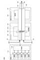
図1は、吸引装置の第1の構成例を模式的に示す模式図である。図1に示すように、本構成例に係る吸引装置100Aは、電源ユニット110、カートリッジ120、及び香味付与カートリッジ130を含む。電源ユニット110は、電源部111A、センサ部112A、通知部113A、記憶部114A、通信部115A、及び制御部116Aを含む。カートリッジ120は、加熱部121A、液誘導部122、及び液貯蔵部123を含む。香味付与カートリッジ130は、香味源131、及びマウスピース124を含む。カートリッジ120及び香味付与カートリッジ130には、空気流路180が形成される。 (1) First Configuration Example Fig. 1 is a schematic diagram showing a first configuration example of an inhalation device. As shown in Fig. 1, an
電源部111Aは、電力を蓄積する。そして、電源部111Aは、制御部116Aによる制御に基づいて、吸引装置100Aの各構成要素に電力を供給する。電源部111Aは、例えば、リチウムイオン二次電池等の充電式バッテリにより構成され得る。The
センサ部112Aは、吸引装置100Aに関する各種情報を取得する。一例として、センサ部112Aは、マイクロホンコンデンサ等の圧力センサ、流量センサ又は温度センサ等により構成され、ユーザによる吸引に伴う値を取得する。他の一例として、センサ部112Aは、ボタン又はスイッチ等の、ユーザからの情報の入力を受け付ける入力装置により構成される。The
通知部113Aは、情報をユーザに通知する。通知部113Aは、例えば、発光する発光装置、画像を表示する表示装置、音を出力する音出力装置、又は振動する振動装置等により構成される。The
記憶部114Aは、吸引装置100Aの動作のための各種情報を記憶する。記憶部114Aは、例えば、フラッシュメモリ等の不揮発性の記憶媒体により構成される。The
通信部115Aは、有線又は無線の任意の通信規格に準拠した通信を行うことが可能な通信インタフェースである。かかる通信規格としては、例えば、Wi-Fi(登録商標)、又はBluetooth(登録商標)等が採用され得る。The
制御部116Aは、演算処理装置及び制御装置として機能し、各種プログラムに従って吸引装置100A内の動作全般を制御する。制御部116Aは、例えばCPU(Central Processing Unit)、及びマイクロプロセッサ等の電子回路によって実現される。The
液貯蔵部123は、エアロゾル源を貯蔵する。エアロゾル源が霧化されることで、エアロゾルが生成される。エアロゾル源は、例えば、グリセリン及びプロピレングリコール等の多価アルコール、並びに水等の液体である。エアロゾル源は、たばこ由来又は非たばこ由来の香味成分を含んでいてもよい。吸引装置100Aがネブライザ等の医療用吸入器である場合、エアロゾル源は、薬剤を含んでもよい。The
液誘導部122は、液貯蔵部123に貯蔵された液体であるエアロゾル源を、液貯蔵部123から誘導し、保持する。液誘導部122は、例えば、ガラス繊維等の繊維素材又は多孔質状のセラミック等の多孔質状素材を撚って形成されるウィックである。その場合、液貯蔵部123に貯蔵されたエアロゾル源は、ウィックの毛細管効果により誘導される。The
加熱部121Aは、エアロゾル源を加熱することで、エアロゾル源を霧化してエアロゾルを生成する。図1に示した例では、加熱部121Aは、コイルとして構成され、液誘導部122に巻き付けられる。加熱部121Aが発熱すると、液誘導部122に保持されたエアロゾル源が加熱されて霧化され、エアロゾルが生成される。加熱部121Aは、電源部111Aから給電されると発熱する。一例として、ユーザが吸引を開始したこと、及び/又は所定の情報が入力されたことが、センサ部112Aにより検出された場合に、給電されてもよい。そして、ユーザが吸引を終了したこと、及び/又は所定の情報が入力されたことが、センサ部112Aにより検出された場合に、給電が停止されてもよい。The
香味源131は、エアロゾルに香味成分を付与するための構成要素である。香味源131は、たばこ由来又は非たばこ由来の香味成分を含んでいてもよい。The
空気流路180は、ユーザに吸引される空気の流路である。空気流路180は、空気流路180内への空気の入り口である空気流入孔181と、空気流路180からの空気の出口である空気流出孔182と、を両端とする管状構造を有する。空気流路180の途中には、上流側(空気流入孔181に近い側)に液誘導部122が配置され、下流側(空気流出孔182に近い側)に香味源131が配置される。ユーザによる吸引に伴い空気流入孔181から流入した空気は、加熱部121Aにより生成されたエアロゾルと混合され、矢印190に示すように、香味源131を通過して空気流出孔182へ輸送される。エアロゾルと空気との混合流体が香味源131を通過する際には、香味源131に含まれる香味成分がエアロゾルに付与される。The
マウスピース124は、吸引の際にユーザに咥えられる部材である。マウスピース124には、空気流出孔182が配置される。ユーザは、マウスピース124を咥えて吸引することで、エアロゾルと空気との混合流体を口腔内へ取り込むことができる。The
以上、吸引装置100Aの構成例を説明した。もちろん吸引装置100Aの構成は上記に限定されず、以下に例示する多様な構成をとり得る。The above describes an example of the configuration of the
一例として、吸引装置100Aは、香味付与カートリッジ130を含んでいなくてもよい。その場合、カートリッジ120にマウスピース124が設けられる。As an example, the
他の一例として、吸引装置100Aは、複数種類のエアロゾル源を含んでいてもよい。複数種類のエアロゾル源から生成された複数種類のエアロゾルが空気流路180内で混合され化学反応を起こすことで、さらに他の種類のエアロゾルが生成されてもよい。As another example, the
また、エアロゾル源を霧化する手段は、加熱部121Aによる加熱に限定されない。例えば、エアロゾル源を霧化する手段は、振動霧化、又は誘導加熱であってもよい。In addition, the means for atomizing the aerosol source is not limited to heating by the
(2)第2の構成例
図2は、吸引装置の第2の構成例を模式的に示す模式図である。図2に示すように、本構成例に係る吸引装置100Bは、電源部111B、センサ部112B、通知部113B、記憶部114B、通信部115B、制御部116B、加熱部121B、保持部140、及び断熱部144を含む。 (2) Second Configuration Example Fig. 2 is a schematic diagram showing a second configuration example of the suction device. As shown in Fig. 2, the
電源部111B、センサ部112B、通知部113B、記憶部114B、通信部115B、及び制御部116Bの各々は、第1の構成例に係る吸引装置100Aに含まれる対応する構成要素と実質的に同一である。Each of the
保持部140は、内部空間141を有し、内部空間141にスティック型基材150の一部を収容しながらスティック型基材150を保持する。保持部140は、内部空間141を外部に連通する開口142を有し、開口142から内部空間141に挿入されたスティック型基材150を保持する。例えば、保持部140は、開口142及び底部143を底面とする筒状体であり、柱状の内部空間141を画定する。保持部140は、スティック型基材150へ供給される空気の流路を画定する機能も有する。かかる流路への空気の入り口である空気流入孔は、例えば底部143に配置される。他方、かかる流路からの空気の出口である空気流出孔は、開口142である。The holding
スティック型基材150は、基材部151、及び吸口部152を含む。基材部151は、エアロゾル源を含む。なお、本構成例において、エアロゾル源は液体に限られるものではなく、固体であってもよい。スティック型基材150が保持部140に保持された状態において、基材部151の少なくとも一部は内部空間141に収容され、吸口部152の少なくとも一部は開口142から突出する。そして、開口142から突出した吸口部152をユーザが咥えて吸引すると、図示しない空気流入孔から内部空間141に空気が流入し、基材部151から発生するエアロゾルと共にユーザの口内に到達する。The stick-shaped
加熱部121Bは、第1の構成例に係る加熱部121Aと同様の構成を有する。ただし、図2に示した例では、加熱部121Bは、フィルム状に構成され、保持部140の外周を覆うように配置される。そして、加熱部121Bが発熱すると、スティック型基材150の基材部151が外周から加熱され、エアロゾルが生成される。The
断熱部144は、加熱部121Bから他の構成要素への伝熱を防止する。例えば、断熱部144は、真空断熱材、又はエアロゲル断熱材等により構成される。The insulating
以上、吸引装置100Bの構成例を説明した。もちろん吸引装置100Bの構成は上記に限定されず、以下に例示する多様な構成をとり得る。The above describes an example of the configuration of the
一例として、加熱部121Bは、ブレード状に構成され、保持部140の底部143から内部空間141に突出するように配置されてもよい。その場合、ブレード状の加熱部121Bは、スティック型基材150の基材部151に挿入され、スティック型基材150の基材部151を内部から加熱する。他の一例として、加熱部121Bは、保持部140の底部143を覆うように配置されてもよい。また、加熱部121Bは、保持部140の外周を覆う第1の加熱部、ブレード状の第2の加熱部、及び保持部140の底部143を覆う第3の加熱部のうち、2以上の組み合わせとして構成されてもよい。As one example, the
他の一例として、保持部140は、内部空間141を形成する外殻の一部を開閉する、ヒンジ等の開閉機構を含んでいてもよい。そして、保持部140は、外殻を開閉することで、内部空間141に挿入されたスティック型基材150を挟持してもよい。その場合、加熱部121Bは、保持部140における当該挟持箇所に設けられ、スティック型基材150を押圧しながら加熱してもよい。As another example, the holding
また、エアロゾル源を霧化する手段は、加熱部121Bによる加熱に限定されない。例えば、エアロゾル源を霧化する手段は、誘導加熱であってもよい。In addition, the means for atomizing the aerosol source is not limited to heating by the
また、吸引装置100Bは、第1の構成例に係る加熱部121A、液誘導部122、液貯蔵部123、及び空気流路180をさらに含んでいてもよく、空気流路180の空気流出孔182が内部空間141への空気流入孔を兼ねていてもよい。この場合、加熱部121Aにより生成されたエアロゾルと空気との混合流体は、内部空間141に流入して加熱部121Bにより生成されたエアロゾルとさらに混合され、ユーザの口腔内に到達する。In addition, the
<<2.技術的特徴>>
<2.1.システム構成例>
図3は、本実施形態に係る販売システム1の構成の一例を示す図である。図3に示すように、販売システム1は、吸引装置100、ユーザ端末200、販売端末300及びサーバ400を含む。なお、図3では、販売システム1が、2つの吸引装置100(100A及び100B)、2つのユーザ端末200(200A及び200B)、1つの販売端末300、及び1つのサーバ400を有する例を示しているが、販売システム1に含まれる各装置の個数はかかる例に限定されない。 <<2. Technical features>>
2.1. System configuration example
Fig. 3 is a diagram showing an example of the configuration of the
(1)吸引装置100の構成
吸引装置は、ユーザにより吸引される物質を生成する装置である。以下では、吸引装置により生成される物質が、エアロゾルであるものとして説明する。他に、吸引装置により生成される物質は、気体であってもよい。以下では、吸引装置により生成された物質をユーザが吸引することを、「吸引」又は「パフ」とも称する。 (1) Configuration of the
本実施形態に係る吸引装置100は、基材を用いてユーザに吸引されるエアロゾルを生成する。加熱部121は、エアロゾルを生成する生成部の一例である。第1の構成例におけるカートリッジ120及び香味付与カートリッジ130、並びに第2の構成例におけるスティック型基材150は、本発明における基材の一例である。吸引装置100は、吸引装置100に装着された基材を用いてエアロゾルを生成する。第1の構成例において、電源ユニット110に接続されたカートリッジ120及び香味付与カートリッジ130は、吸引装置100に装着された基材の一例である。第2の構成例において、吸引装置100に挿入されたスティック型基材150は、吸引装置100に装着された基材の一例である。The
吸引装置100は、上記説明した第1の構成例、又は第2の構成例のうち任意の構成例を取り得る。図3では、ユーザAにより使用される吸引装置100を吸引装置100Aとし、ユーザBにより使用される吸引装置100を吸引装置100Bとしている。つまり、図3における吸引装置100Aの構成は、図1に示した構成と必ずしも一致していなくてもよく、例えば図2に示した構成と一致していてもよい。同様に、図3における吸引装置100Bの構成は、図2に示した構成と必ずしも一致していなくてもよく、例えば図1に示した構成と一致していてもよい。The
とりわけ、本実施形態に係る通信部115は、NFC(Near Field Communication)又はBluetooth(登録商標)の近距離無線通信規格に準拠した無線通信を行い得る。In particular, the communication unit 115 in this embodiment can perform wireless communication in accordance with the NFC (Near Field Communication) or Bluetooth (registered trademark) short-range wireless communication standards.
(2)ユーザ端末200の構成
ユーザ端末200は、吸引装置100のユーザにより使用される端末装置である。例えば、ユーザ端末200は、スマートフォン、タブレット端末又はウェアラブルデバイス等により構成される。同一ユーザにより使用される吸引装置100とユーザ端末200とは、互いに対応付けられる。例えば、ユーザは、ユーザ端末200に吸引装置100の情報を登録したり、吸引装置100にユーザ端末200の情報を登録したり、サーバ400に吸引装置100及びユーザ端末200が同一ユーザにより使用されることを登録したりする。以下、図4を参照しながら、ユーザ端末200の構成について説明する。 (2) Configuration of
図4は、本実施形態に係るユーザ端末200の構成の一例を示すブロック図である。図4に示すように、ユーザ端末200は、入力部210、出力部220、通信部230、記憶部240、及び制御部250を含む。Figure 4 is a block diagram showing an example of the configuration of a
入力部210は、各種情報の入力を受け付ける機能を有する。入力部210は、ユーザからの情報の入力を受け付ける入力装置を含んでいてもよい。入力装置としては、例えば、ボタン、キーボード、タッチパネル、及びマイク等が挙げられる。他にも、入力部210は、画像センサ等の各種センサを含んでいてもよい。The
出力部220は、情報を出力する機能を有する。出力部220は、ユーザに対し情報を出力する出力装置を含んでいてもよい。出力装置としては、例えば、情報を表示する表示装置、発光する発光装置、振動する振動装置、及び音を出力する音出力装置等が挙げられる。表示装置の一例は、ディスプレイである。発光装置の一例は、LED(Light Emitting Diode)である。振動装置の一例は、偏心モータである。音出力装置の一例は、スピーカである。出力部220は、制御部250から入力された情報を出力することで、情報をユーザに通知する。The
通信部230は、ユーザ端末200と他の装置との間で情報の送受信を行うための、通信インタフェースである。通信部230は、有線又は無線の任意の通信規格に準拠した通信を行う。かかる通信規格としては、例えば、無線LAN(Local Area Network)、有線LAN、Wi-Fi(登録商標)、又はBluetooth(登録商標)等が採用され得る。とりわけ、通信部230は、NFC(Near Field Communication)又はBluetooth(登録商標)等の近距離無線通信規格に準拠した無線通信を行い得る。The
記憶部240は、ユーザ端末200の動作のための各種情報を記憶する。記憶部240は、例えば、フラッシュメモリ等の不揮発性の記憶媒体により構成される。The
制御部250は、演算処理装置及び制御装置として機能し、各種プログラムに従ってユーザ端末200内の動作全般を制御する。制御部250は、例えばCPU(Central Processing Unit)、及びマイクロプロセッサ等の電子回路によって実現される。他に、制御部250は、使用するプログラム及び演算パラメータ等を記憶するROM(Read Only Memory)、並びに適宜変化するパラメータ等を一時記憶するRAM(Random Access Memory)を含んでいてもよい。ユーザ端末200は、制御部250による制御に基づいて、各種処理を実行する。入力部210により入力された情報の処理、出力部220による情報の出力、通信部230による情報の送受信、並びに記憶部240による情報の記憶及び読み出しは、制御部250により制御される処理の一例である。各構成要素への情報の入力、及び各構成要素から出力された情報に基づく処理等、ユーザ端末200により実行されるその他の処理も、制御部250により制御される。The
なお、制御部250の機能は、アプリケーションを用いて実現されてもよい。当該アプリケーションは、プリインストールされていてもよいし、ダウンロードされてもよい。また、制御部250の機能は、PWA(Progressive Web Apps)により実現されてもよい。The functions of the
(3)販売端末300の構成
販売端末300は、基材を販売するための処理を行う端末装置である。販売端末300は、例えば、キャッシュレジスタ、又はPOS(Point Of Sales)端末として構成され得る。その場合、販売端末300は、基材を販売する店に設置される。基材を販売するための処理としては、例えば、金銭授受に係る会計処理、及び販売された基材の銘柄及び個数等を登録する販売管理処理等が挙げられる。販売端末300を使用するユーザは、典型的には店員である。 (3) Configuration of
販売端末300は、他の装置との間で、有線又は無線の任意の通信規格に準拠した通信を行う。一例として、販売端末300は、NFC(Near Field Communication)又はBluetooth(登録商標)の近距離無線通信規格に準拠した無線通信を行い得る。The
(4)サーバ400の構成
サーバ400は、吸引装置100に関する各種のサービスを提供する情報処理装置である。一例として、サーバ400は、吸引装置100のユーザに対する会員サービスを提供する。サーバ400は、吸引装置100の情報(より正確には、後述するフロントパネル160に記憶された情報)を収集及び蓄積し、蓄積された情報の分析を行い、分析結果に応じた会員サービスを提供する。例えば、ユーザは、サーバ400にアクセスして会員登録を予め行うことで、吸引装置100に関する情報提供等の各種の会員サービスを受けることができる。 (4) Configuration of
<2.2.アクセサリの装着に関する特徴>
(1)フロントパネルの構成
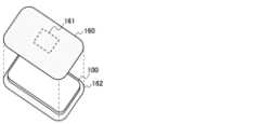
吸引装置100には、着脱可能に吸引装置100に装着されるアクセサリが装着され得る。図5は、本実施形態の第2の構成例に係る吸引装置100に装着されるアクセサリの一例を示す図である。図5に示すように、吸引装置100には、フロントパネル160が着脱可能に装着されてもよい。フロントパネル160とバックパネル162とは、間に吸引装置100を挟むようにして接合されることで、吸引装置100の外周を覆う外殻を形成する。フロントパネル160は、アクセサリの一例である。 2.2. Features related to attachment of accessories
(1) Configuration of the Front Panel An accessory that is detachably attached to the
フロントパネル160は、NFCタグ161を備える。NFCタグ161は、無線通信機能と記憶機能とを兼ね備え、無線通信を介して情報を読み書きされる。詳しくは、NFCタグ161は、NFCリーダライタとの間でNFCによる無線通信を行い、NFCリーダライタに情報を送信し、NFCリーダライタから受信した情報を記憶する。NFCは、ペアリングが不要であるから、不特定の装置との間で無線通信する際に高いユーザビリティを発揮する。The
(2)フロントパネルに関する各装置の処理
(2.1)ユーザ端末200による処理
ユーザ端末200は、フロントパネル160に記憶される情報を管理する。一例として、ユーザ端末200は、NFCタグ161との間で同期をとる。詳しくは、ユーザ端末200は、NFCタグ161に記憶された情報とユーザ端末200に記憶された情報とが一致するように、NFCタグ161に情報を書き込む、又はNFCタグ161から情報を読み取って記憶する。このようにして同期される情報を、以下では同期対象の情報とも称する。NFCタグ161に記憶される情報を管理する機能は、専用のアプリケーション(以下、管理用アプリケーションとも称する)により実現され得る。 (2) Processing of each device related to the front panel (2.1) Processing by the
同期対象の情報の一例を、以下に説明する。同期対象の情報は、以下に説明する情報の少なくともいずれかを含む。An example of information to be synchronized is described below. The information to be synchronized includes at least one of the information described below.
-銘柄情報
同期対象の情報は、基材の識別情報を含んでいてもよい。基材の識別情報とは、基材の銘柄(即ち、種類)を識別するための情報である。以下、基材の識別情報を、銘柄情報とも称する。銘柄情報は、販売端末300に送信された場合、購入を希望する銘柄を示す情報として取り扱われる。そのため、同期対象の情報として銘柄情報が販売端末300に送信されることで、基材購入時のユーザビリティを向上させることが可能である。 - Brand information The information to be synchronized may include identification information of the base material. The identification information of the base material is information for identifying the brand (i.e., type) of the base material. Hereinafter, the identification information of the base material is also referred to as brand information. When the brand information is transmitted to the
例えば、ユーザ端末200は、サーバ400から提供される会員サービス又はWebサイトから銘柄情報を取得し、フロントパネル160に書き込んでもよい。他の一例として、ユーザ端末200は、基材のパッケージを撮像した撮像画像に画像認識を適用することで取得した銘柄情報を、フロントパネル160に書き込んでもよい。ユーザ端末200は、以下に説明する他の情報についても同様に、会員サービス又はWebサービスから取得し、フロントパネル160に書き込んでもよい。For example, the
-プロファイル情報
同期対象の情報は、吸引装置100がエアロゾルを生成するために行う基材を加熱する動作を規定するプロファイルを示すプロファイル情報を含んでいてもよい。吸引装置100は、プロファイル情報により示されるプロファイルに従って基材を加熱し、エアロゾルを生成する。 Profile Information The information to be synchronized may include profile information indicating a profile that specifies the operation of heating the substrate performed by the
第1の構成例におけるプロファイルは、加熱部121Aへの給電時間、及び単位時間当たりの給電量(例えば、電圧)を定義する情報である。制御部116は、プロファイルにおいて定義された単位時間当たりの給電量を、プロファイルにおいて定義された給電時間、電源部111から加熱部121Aに給電されるよう制御する。このような給電の制御は、例えば、パフが1回検出される度に行われる。The profile in the first configuration example is information that defines the power supply time to the
第2の構成例におけるプロファイルは、加熱部121Bによる加熱開始からの経過時間と加熱部121Bの温度との関係を定義する情報である。制御部116は、プロファイルにおける温度変化と同様の温度変化が加熱部121Bにおいて実現されるよう、加熱部121Bを制御する。加熱部121Bは、抵抗器を含む導電トラックを含んでいてもよく、センサ部112は、導電トラックの電気抵抗に基づいて加熱部121Bの温度を検出してもよい。加熱部121Bの制御は、例えば電源部111から加熱部121Bへの給電を制御することにより、実現され得る。給電の制御は、例えば、PWM(Pulse Width Modulation)制御により行われてもよい。The profile in the second configuration example is information that defines the relationship between the time elapsed since heating by
プロファイル情報は、プロファイルそのものであってもよい。プロファイルは、会員サービスにより提供される等、設定可能なプロファイルが予め決まっていてもよい。その場合、プロファイル情報は、プロファイルを示す識別情報であってもよい。プロファイルを示す識別情報は、プロファイルそのものと比較してデータ量が少ないので、他の装置と送受信する際の通信負荷が軽減される。他にも、プロファイルは、給電時間等のパラメータがユーザにより調節される等、ユーザによるカスタマイズが可能であってもよい。The profile information may be the profile itself. The profile may be a preset profile that can be set, such as provided by a membership service. In that case, the profile information may be identification information indicating the profile. Since the identification information indicating the profile has a smaller amount of data than the profile itself, the communication load when transmitting and receiving with other devices is reduced. Additionally, the profile may be customizable by the user, such as by allowing the user to adjust parameters such as power supply time.
-銘柄情報とプロファイル情報との組み合わせ
銘柄情報とプロファイル情報とは対応付けられていてもよい。例えば、基材ごとにユーザが好むプロファイルが異なっていてもよく、銘柄情報と当該銘柄情報により示される銘柄の基材に好適なプロファイルとが対応付けられてもよい。そのため、同期対象の情報として、銘柄情報とプロファイル情報とが対応付けられて送受信されてもよい。また、同期対象の情報は、銘柄情報とプロファイル情報との組み合わせを示す識別情報を含んでいてもよい。銘柄情報とプロファイル情報との組み合わせを示す識別情報のデータ量が、銘柄情報のデータ量及びプロファイル情報のデータ量の総和よりも少なくなるよう設計することで、他の装置と送受信する際の通信負荷を軽減することができる。銘柄情報とプロファイル情報との組み合わせを示す識別情報の一例を、下記の表1に示す。 - Combination of stock information and profile information Stock information and profile information may be associated. For example, a profile preferred by a user may differ for each substrate, and stock information may be associated with a profile suitable for a substrate of a stock indicated by the stock information. Therefore, stock information and profile information may be associated and transmitted as information to be synchronized. In addition, the information to be synchronized may include identification information indicating a combination of stock information and profile information. By designing the data amount of the identification information indicating the combination of stock information and profile information to be less than the sum of the data amount of the stock information and the profile information, the communication load when transmitting and receiving with other devices can be reduced. An example of identification information indicating a combination of stock information and profile information is shown in Table 1 below.

-デバイスID
同期対象の情報は、吸引装置100の識別情報を含んでいてもよい。吸引装置100の識別情報とは、吸引装置100を一意に識別するための情報である。吸引装置100の識別情報を、以下ではデバイスIDとも称する。 - Device ID
The information to be synchronized may include identification information of the
-ユーザID
同期対象の情報は、吸引装置100を使用するユーザの識別情報を含んでいてもよい。ユーザの識別情報とは、ユーザを一意に識別するための情報である。ユーザの識別情報を、以下ではユーザIDとも称する。ユーザIDは、ユーザの名前等の個人情報であってもいし、会員サービスに登録されたアカウント名であってもよい。 - User ID
The information to be synchronized may include identification information of the user who uses the
-認証情報
同期対象の情報は、認証情報を含んでいてもよい。認証情報とは、基材をユーザが購入する資格を有する旨を示す情報である。認証情報は、例えば、ユーザの年齢を証明する情報を含む。 -Authentication Information The information to be synchronized may include authentication information. Authentication information is information that indicates that a user is qualified to purchase a base material. The authentication information includes, for example, information that proves the user's age.
(2.2)販売端末300による処理
販売端末300は、フロントパネル160に記憶された情報を読み取り、読み取った情報に応じた各種処理を行う。 (2.2) Processing by Vending
一例として、販売端末300は、吸引装置100から受信した情報に応じて基材を販売するための処理を行ってもよい。例えば、販売端末300は、吸引装置100から受信した銘柄情報により示される銘柄の基材を、ユーザが購入を希望する基材として、販売する処理を行ってもよい。かかる構成によれば、ユーザは、購入希望の基材を店員に口頭で指定したりせずとも、希望通りの基材を購入することが可能となる。As an example, the
他の一例として、販売端末300は、吸引装置100から受信した情報の少なくとも一部をサーバ400に送信する。サーバ400では、後述するように、受信した情報の蓄積及び分析が行われ、分析結果に応じた会員サービスが提供される。よって、ユーザは、吸引装置100を用いて基材を購入するだけで、即ちユーザ端末200を操作してサーバ400に情報を送信する手間を負うことなく、会員の購買行動を反映した好適な会員サービスを受けることが可能となる。As another example, the
他の一例として、販売端末300は、吸引装置100から受信した認証情報に基づいて認証を行ってもよい。例えば、販売端末300は、認証情報により示されるユーザの年齢が所定の年齢以上である場合に認証成功を判定し、それ以外の場合に認証失敗を判定する。かかる構成によれば、基材を購入する資格を有さないユーザに対し基材を誤って販売してしまうことを防止することが可能となる。As another example, the
(2.3)サーバ400による処理
サーバ400は、販売端末300を介して、フロントパネル160に記憶された情報を収集する。サーバ400は、収集した情報を蓄積して分析を行い、分析結果に基づいて会員サービスを提供する。 (2.3) Processing by
一例として、サーバ400は、収集した情報を、銘柄情報ごとに集計することで、数多く購入された銘柄、即ち会員内で流行している銘柄を特定してもよい。そして、サーバ400は、会員内で流行している銘柄をおすすめする情報を、会員サービスとして提供してもよい。As an example,
他の一例として、サーバ400は、収集した情報を、プロファイル情報ごとに集計することで、数多く利用されているプロファイル、即ち会員内で流行しているプロファイルを特定してもよい。そして、サーバ400は、会員内で流行しているプロファイルをおすすめする情報を、会員サービスとして提供してもよい。As another example,
他の一例として、ユーザID又はデバイスIDと銘柄情報との組み合わせに基づいて、販売端末300がどのユーザにどの銘柄の基材を販売したか、即ちどのユーザがどの基材を購入したかを分析してもよい。As another example, based on a combination of a user ID or device ID and brand information, the
(3)フロントパネル160の着せ替え
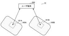
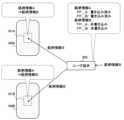
ユーザは、複数のフロントパネル160を所有し、そのいずれかひとつを吸引装置100に装着しながら、吸引装置100を使用する。そのようなシステムの一例を、図6を参照しながら説明する。 (3) Changing the
図6は、本実施形態に係る着せ替えシステム10の構成の一例を示す図である。図6に示すように、着せ替えシステム10は、ユーザ端末200、及び複数のフロントパネル160を含む。着せ替えシステム10は、これら複数のフロントパネル160が装着される吸引装置100も含んでいてもよい。着せ替えシステム10に含まれる各装置は、典型的には、同一のユーザにより所有される。吸引装置100には、フロントパネル160A及びフロントパネル160Bのいずれかが装着され得る。ユーザは、例えばその日の気分に応じて吸引装置100にフロントパネル160を着せ替えることができる。Figure 6 is a diagram showing an example of the configuration of the dress-up
ここで、フロントパネル160A(正確には、NFCタグ161A)に記憶されている情報とフロントパネル160B(正確には、NFCタグ161B)に記憶されている情報とに相違がある場合、着せ替え前後で様々な不都合が生じ得る。例えば、フロントパネル160Aとフロントパネル160Bとで記憶している銘柄情報が異なっており、ユーザがそれを認識せずに基材を購入した場合、ユーザは、着せ替え後に着せ替え前の異なる銘柄の基材を意図せず購入することとなる。Here, if there is a difference between the information stored in
そこで、ユーザ端末200は、複数のフロントパネル160が共通して記憶するべき情報である同期対象の情報を記憶し、複数のフロントパネル160の各々との間で同期をとる。即ち、ユーザ端末200は、ユーザ端末200に記憶された同期対象の情報を、無線通信を介して複数のフロントパネル160の各々に書き込む。詳しくは、記憶部240は、上述した同期対象の情報を、複数のフロントパネル160が共通して記憶するべき情報として記憶する。そして、制御部250は、記憶部240に記憶された同期対象の情報を、通信部230による無線通信を介してフロントパネル160に書き込む処理を制御する。当該書き込む処理は、NFCタグ161とのNFC通信の確立、及び同期対象の情報の送信を含む。例えば、ユーザ端末200は、NFCタグ161A及びNFCタグ161Bの双方に、共通する同期対象の情報を書き込む。かかる構成により、複数のフロントパネル160のNFCタグ161に記憶される情報が同期されるので、上述した不都合を回避することが可能となる。Therefore, the
ユーザ端末200は、ユーザ端末200に記憶された同期対象の情報の方が、フロントパネル160に記憶された同期対象の情報よりも新しい場合に、ユーザ端末200に記憶された同期対象の情報をフロントパネル160に書き込む。かかる構成により、複数のフロントパネル160の各々に記憶される情報を、最新の情報に更新することが可能となる。When the information to be synchronized stored in the
ユーザ端末200は、フロントパネル160に記憶された同期対象の情報の方が、ユーザ端末200に記憶された同期対象の情報よりも新しい場合に、フロントパネル160に記憶された情報を同期対象の情報として取得し記憶する。フロントパネル160には、ユーザ端末200以外の他の装置(例えば、他のユーザにより使用される他のユーザ端末200)から情報が書き込まれる可能性がある。この点、かかる構成によれば、他の装置により書き込まれた情報を最新の同期対象の情報として、複数のフロントパネル160により同期することが可能となる。When the information to be synchronized stored in the
ユーザ端末200に記憶された同期対象の情報及びフロントパネル160に記憶された同期対象の情報のいずれが新しいかを判定する手法は、多様に考えられる。以下、その一例として、時刻情報に基づく判定手法、及び書き込み履歴に基づく判定手法について説明する。There are various methods for determining which of the information to be synchronized stored in the
-時刻情報に基づく判定手法
ユーザ端末200は、同期対象の情報と時刻を示す時刻情報とを対応付けて記憶し、同期対象の情報と時刻情報とを対応付けてフロントパネル160に書き込む。そして、ユーザ端末200は、ユーザ端末200に記憶された時刻情報とフロントパネル160に記憶された時刻情報とを比較することで、ユーザ端末200に記憶された同期対象の情報をフロントパネル160に書き込むか否かを判定する。ユーザ端末200に記憶された時刻情報により示される時刻、及びフロントパネル160に記憶された時刻情報により示される時刻が一致することは、フロントパネル160に最新の情報が書き込まれていることを意味する。他方、これらの時刻が相違することは、ユーザ端末200に記憶された同期対象の情報、及びフロントパネル160に記憶された同期対象の情報の一方が、他方より新しいことを意味する。 -Determination method based on time information The
詳しくは、ユーザ端末200に記憶された時刻情報により示される時刻の方が、フロントパネル160に記憶された時刻情報により示される時刻より新しいことは、フロントパネル160に古い情報が書き込まれていることを意味する。そこで、ユーザ端末200は、ユーザ端末200に記憶された同期対象の情報をフロントパネル160に書き込む。In more detail, if the time indicated by the time information stored in the
フロントパネル160に記憶された時刻情報により示される時刻の方が、ユーザ端末200に記憶された時刻情報により示される時刻より新しいことは、フロントパネル160に新しい情報が書き込まれていることを意味する。そこで、ユーザ端末200は、フロントパネル160に記憶された同期対象の情報を取得し記憶する。If the time indicated by the time information stored in the
以上説明した構成によれば、ユーザ端末200に記憶された同期対象の情報及びフロントパネル160に記憶された同期対象の情報のいずれが新しいかを判定することが可能となる。そのため、ユーザ端末200は、ユーザ端末200又はフロントパネル160のいずれかに記憶された同期対象の情報を最新に更新すること、即ちフロントパネル160との間で同期をとることが可能となる。According to the configuration described above, it is possible to determine which of the information to be synchronized stored in the
ここで、時刻情報は、同期対象の情報が取得された時刻を示す。一例として、銘柄情報に対応付けられる時刻情報は、ユーザ端末200が当該銘柄情報をWebサイト又はパッケージから取得した時刻を示す。ここでの時刻とは、日時を含む概念である。かかる構成によれば、ユーザ端末200により新たに取得された情報を、複数のフロントパネル160の各々に共通して記憶させることが可能となる。Here, the time information indicates the time when the information to be synchronized was acquired. As an example, the time information associated with the stock information indicates the time when the
以下、本判定方法の具体例を、図7及び図8を参照しながら説明する。Below, a specific example of this determination method is explained with reference to Figures 7 and 8.
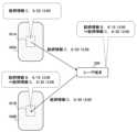
図7は、本実施形態に係る同期処理の具体例を説明するための図である。図7に示すように、フロントパネル160A(より正確には、NFCタグ161A)及びフロントパネル160B(より正確には、NFCタグ161B)は、銘柄情報Aを時刻情報「6月12日12:00」に対応付けて記憶している。ユーザ端末200は、6月19日12:00に銘柄情報BをWebサイト等から取得すると、銘柄情報Bを、時刻情報「6月19日12:00」に対応付けて記憶している。ユーザ端末200は、フロントパネル160Aから銘柄情報A及び時刻情報「6月12日12:00」を読み取ると、読み取った時刻情報「6月12日12:00」と記憶している時刻情報「6月19日12:00」とを比較し、銘柄情報Bの方が新しいと判定する。そこで、ユーザ端末200は、銘柄情報Bを時刻情報「6月19日12:00」に対応付けてフロントパネル160Aに書き込む。ユーザ端末200は、フロントパネル160Bについても同様の処理を行う。FIG. 7 is a diagram for explaining a specific example of the synchronization process according to the present embodiment. As shown in FIG. 7, the
図8は、本実施形態に係る同期処理の具体例を説明するための図である。本具体例は、図7に示した具体例の後に、銘柄情報Cが他のユーザ端末200によりフロントパネル160Aに書き込まれた場合の例である。図8に示すように、フロントパネル160A(より正確には、NFCタグ161A)は、銘柄情報Cを時刻情報「6月20日12:00」に対応付けて記憶している。他方、フロントパネル160B(より正確には、NFCタグ161B)は、銘柄情報Bを時刻情報「6月19日12:00」に対応付けて記憶している。ユーザ端末200は、銘柄情報Bを、時刻情報「6月19日12:00」に対応付けて記憶している。ユーザ端末200は、フロントパネル160Aから銘柄情報C及び時刻情報「6月20日12:00」を読み取ると、読み取った時刻情報「6月20日12:00」と記憶している時刻情報「6月19日12:00」とを比較し、銘柄情報Cの方が新しいと判定する。そこで、ユーザ端末200は、銘柄情報Cを、時刻情報「6月20日12:00」に対応付けて記憶する。他方、ユーザ端末200は、フロントパネル160Bから銘柄情報B及び時刻情報「6月19日12:00」を読み取ると、読み取った時刻情報「6月19日12:00」と記憶している時刻情報「6月20日12:00」とを比較し、銘柄情報Cの方が新しいと判定する。そこで、ユーザ端末200は、銘柄情報Cを、時刻情報「6月20日12:00」に対応付けてフロントパネル160Bに書き込む。Figure 8 is a diagram for explaining a specific example of the synchronization process according to this embodiment. This specific example is an example in which, after the specific example shown in Figure 7, brand information C is written to the
-書き込み履歴に基づく判定手法
ユーザ端末200は、ユーザ端末200に記憶された同期対象の情報を書き込み済みのフロントパネル160を記憶する。例えば、ユーザ端末200は、複数のフロントパネル160の各々について、ユーザ端末200が記憶している同期対象の情報を書き込み済みであるか否かを記憶する。そして、ユーザ端末200は、複数のフロントパネル160のうちユーザ端末200に記憶された同期対象の情報がまだ書き込まれていないフロントパネル160に、ユーザ端末200に記憶された同期対象の情報を書き込む。かかる構成によれば、ユーザ端末200により新たに取得された情報を、複数のフロントパネル160の各々に共通して記憶させることが可能となる。 -Determination method based on writing history The
以下、本判定方法の具体例を、図9及び図10を参照しながら説明する。Below, a specific example of this determination method is explained with reference to Figures 9 and 10.
図9は、本実施形態に係る同期処理の具体例を説明するための図である。図9に示すように、フロントパネル160A(より正確には、NFCタグ161A)及びフロントパネル160B(より正確には、NFCタグ161B)は、銘柄情報Aを記憶している。ユーザ端末200は、フロントパネル160A及びフロントパネル160Bの各々に対し銘柄情報Aを書き込み済みであることを書き込み履歴として記憶している。なお、図9において、FP_Aとはフロントパネル160Aを示し、FP_Bとはフロントパネル160Bを示す。これらの書き込み履歴は、ユーザ端末200が過去に銘柄情報Aをフロントパネル160A及びフロントパネル160Bの各々に書き込んだ際に、記憶される。ユーザ端末200は、銘柄情報BをWebサイト等から取得すると、銘柄情報Bを同期対象の情報として記憶すると共に、フロントパネル160A及びフロントパネル160Bに対し銘柄情報Bを書き込んでいないことを書き込み履歴として記憶する。そのため、ユーザ端末200は、フロントパネル160Aに対し銘柄情報Bを書き込むと共に、フロントパネル160Aに対し銘柄情報Bを書き込み済みであることを書き込み履歴として記憶する。ユーザ端末200は、フロントパネル160Bについても同様の処理を行う。9 is a diagram for explaining a specific example of the synchronization process according to the present embodiment. As shown in FIG. 9, the
図10は、本実施形態に係る同期処理の具体例を説明するための図である。本具体例は、図9に示した具体例の後に、銘柄情報Cが他のユーザ端末200によりフロントパネル160Aに書き込まれた場合の例である。図10に示すように、フロントパネル160A(より正確には、NFCタグ161A)は、銘柄情報Cを記憶している。フロントパネル160B(より正確には、NFCタグ161B)は、銘柄情報Bを記憶している。ユーザ端末200は、フロントパネル160A及びフロントパネル160Bの各々に対し銘柄情報A及び銘柄情報Bを書き込み済みであることを、書き込み履歴として記憶している。ユーザ端末200は、銘柄情報Cをフロントパネル160Aから読み取ると、銘柄情報Cが書き込み履歴に含まれないことに基づき、銘柄情報Cが他のユーザ端末200から新たに書き込まれた情報であると判定する。そこで、ユーザ端末200は、銘柄情報Cを同期対象の情報として記憶すると共に、フロントパネル160Aに対し銘柄情報Cを書き込み済みであること及びフロントパネル160Bに対し銘柄情報Cを書き込んでいないことを、書き込み履歴として記憶する。そして、ユーザ端末200は、フロントパネル160Bに対し銘柄情報Cを書き込むと共に、フロントパネル160Bに対し銘柄情報Cを書き込み済みであることを書き込み履歴として記憶する。Figure 10 is a diagram for explaining a specific example of the synchronization process according to this embodiment. This specific example is an example in which, after the specific example shown in Figure 9, brand information C is written to the
-同期タイミング
ユーザ端末200は、複数のフロントパネル160のうち、ユーザ端末200との間でNFC通信が確立したフロントパネル160に対して同期を行う。換言すると、ユーザ端末200は、フロントパネル160との間でNFC通信が確立したタイミングで、当該フロントパネル160との間で同期を行う。例えば、ユーザは、ユーザ端末200をフロントパネル160にかざすことで、ユーザ端末200と当該フロントパネル160との間の同期を実行させることができる。 - Synchronization Timing The
さらに、ユーザ端末200は、複数のフロントパネル160のうち、吸引装置100に装着されたフロントパネル160に、ユーザ端末200に記憶された同期対象の情報を書き込んでもよい。換言すると、ユーザ端末200は、フロントパネル160が吸引装置100に装着されたタイミングで、当該フロントパネル160との間で同期を行ってもよい。かかる構成によれば、吸引装置100に装着されたフロントパネル160に対して同期が実行されるので、その他の例えば長期間使用されていないフロントパネル160に対する同期が回避される等、不要な同期を回避することが可能となる。Furthermore, the
ユーザ端末200が、吸引装置100に装着されたフロントパネル160を識別し、識別したフロントパネル160に限定して同期とる手法が多様に考えられる。一例として、吸引装置100とフロントパネル160とが電気的に接続可能に構成される場合、センサ部112は、電気抵抗に基づいて吸引装置100に装着されたフロントパネル160を識別し得る。その場合、吸引装置100は、通信部115によりフロントパネル160の識別結果をユーザ端末200に送信する。これにより、ユーザ端末200は、受信した情報により識別されるフロントパネル160に限定して、同期をとることができる。There are various possible methods by which the
(4)処理の流れ
図11は、本実施形態に係るユーザ端末200において実行される同期処理の流れの一例を説明するためのフローチャートである。 (4) Processing Flow FIG. 11 is a flowchart illustrating an example of the flow of a synchronization process executed in the
図11に示すように、まず、ユーザ端末200は、着せ替えシステム10に属する複数のフロントパネル160のいずれかとの間でNFC通信が成立したか否かを判定する(ステップS102)。As shown in FIG. 11, first, the
NFC通信が成立していないと判定された場合(ステップS102:NO)、ユーザ端末200は、NFC通信が成立するまで待機する。If it is determined that NFC communication has not been established (step S102: NO), the
他方、NFC通信が成立したと判定された場合(ステップS102:YES)、ユーザ端末200は、フロントパネル160から読み取った同期対象の情報の方が、ユーザ端末200に記憶されている同期対象の情報より新しいか否かを判定する(ステップS104)。On the other hand, if it is determined that NFC communication has been established (step S102: YES), the
フロントパネル160から読み取った同期対象の情報の方が新しいと判定された場合(ステップS104:YES)、ユーザ端末200は、読み取った同期対象の情報を記憶する(ステップS106)。If it is determined that the information to be synchronized read from the
他方、ユーザ端末200に記憶されている同期対象の情報の方が新しいと判定された場合(ステップS104:NO)、ユーザ端末200は、ユーザ端末200に記憶された同期対象の情報をフロントパネル160に書き込む(ステップS108)。On the other hand, if it is determined that the information to be synchronized stored in the
<<3.補足>>
以上、添付図面を参照しながら本発明の好適な実施形態について詳細に説明したが、本発明はかかる例に限定されない。本発明の属する技術の分野における通常の知識を有する者であれば、請求の範囲に記載された技術的思想の範疇内において、各種の変更例または修正例に想到し得ることは明らかであり、これらについても、当然に本発明の技術的範囲に属するものと了解される。 <<3. Supplementary Information>>
Although the preferred embodiment of the present invention has been described in detail above with reference to the accompanying drawings, the present invention is not limited to such an example. It is clear that a person having ordinary knowledge in the technical field to which the present invention pertains can conceive of various modified or altered examples within the scope of the technical ideas described in the claims, and it is understood that these also naturally belong to the technical scope of the present invention.
例えば、上記実施形態では、ユーザ端末200が1種類の同期対象の情報を記憶し、複数のフロントパネル160に共通して書き込む例を説明したが、本発明はかかる例に限定されない。ユーザ端末200は、複数種類の同期対象の情報を記憶していてもよい。そして、ユーザ端末200は、例えばユーザにより選択された1種類の同期対象の情報を、複数のフロントパネル160に共通して書き込んでもよい。また、着せ替えシステム10に属する複数のフロントパネル160の各々は、複数のグループのいずれかに分類されてもよい。その場合、ユーザ端末200は、グループごとの同期対象の情報を記憶する。そして、ユーザ端末200は、同一グループに属する複数のフロントパネル160が共通して記憶するべき同期対象の情報を、当該グループに属するフロントパネル160に書き込む。例えば、ユーザ端末200は、プライベート用の同期対象の情報と仕事用の同期対象の情報とを記憶する。そして、ユーザ端末200は、複数のプライベート用のフロントパネル160の各々に対してはプライベート用の同期対象の情報を書き込み、複数の仕事用のフロントパネル160の各々に対しては仕事用の同期対象の情報を書き込む。かかる構成によれば、複数のフロントパネル160を用途ごとに使い分ける際のユーザビリティを向上させることが可能となる。For example, in the above embodiment, an example has been described in which the
上記実施形態では、フロントパネル160にNFCタグ161が搭載される例を説明したが、本発明はかかる例に限定されない。本発明は、通信機能と記憶機能とを備える任意のアクセサリに適用可能である。アクセサリには、NFC以外の他の無線通信規格に準拠した通信機能が搭載されてもよい。他の無線通信規格の一例は、Bluetoothである。In the above embodiment, an example in which the
例えば、上記実施形態では、吸引装置100に装着されるアクセサリとしてフロントパネル160を例示したが、本発明はかかる例に限定されない。アクセサリは、ストラップ及びシール等、吸引装置100に着脱可能な任意の構成をとり得る。For example, in the above embodiment, the
例えば、上記実施形態では、吸引装置100にアクセサリが装着される例を説明したが、本発明はかかる例に限定されない。吸引装置100以外の任意の装置について、本発明は適用可能である。例えば、スマートフォンにスマートフォンケース等のアクセサリが着脱可能に装着されてもよい。そして、スマートフォンの制御が、アクセサリの着脱をトリガとして切り替えられてもよい。For example, in the above embodiment, an example in which an accessory is attached to the
なお、本明細書において説明した各装置による一連の処理は、ソフトウェア、ハードウェア、及びソフトウェアとハードウェアとの組合せのいずれを用いて実現されてもよい。ソフトウェアを構成するプログラムは、例えば、各装置の内部又は外部に設けられる記録媒体(非一時的な媒体:non-transitory media)に予め格納される。そして、各プログラムは、例えば、コンピュータによる実行時にRAMに読み込まれ、CPUなどのプロセッサにより実行される。上記記録媒体は、例えば、磁気ディスク、光ディスク、光磁気ディスク、フラッシュメモリ等である。また、上記のコンピュータプログラムは、記録媒体を用いずに、例えばネットワークを介して配信されてもよい。The series of processes performed by each device described in this specification may be realized using software, hardware, or a combination of software and hardware. The programs constituting the software are stored in advance, for example, in a recording medium (non-transitory media) provided inside or outside each device. Each program is then loaded into RAM, for example, when executed by a computer, and executed by a processor such as a CPU. The recording medium is, for example, a magnetic disk, an optical disk, a magneto-optical disk, a flash memory, etc. The computer programs may also be distributed, for example, via a network, without using a recording medium.
また、本明細書においてフローチャート及びシーケンス図を用いて説明した処理は、必ずしも図示された順序で実行されなくてもよい。いくつかの処理ステップは、並列的に実行されてもよい。また、追加的な処理ステップが採用されてもよく、一部の処理ステップが省略されてもよい。In addition, the processes described in this specification using flowcharts and sequence diagrams do not necessarily have to be performed in the order shown. Some processing steps may be performed in parallel. Furthermore, additional processing steps may be employed, and some processing steps may be omitted.
なお、以下のような構成も本発明の技術的範囲に属する。
(1)
基材を用いてユーザに吸引されるエアロゾルを生成する吸引装置に着脱可能であり、無線通信を介して情報を読み書きされる複数のアクセサリと、
複数の前記アクセサリが共通して記憶するべき情報である同期対象の情報を記憶し、記憶された前記同期対象の情報を、無線通信を介して複数の前記アクセサリの各々に書き込む端末装置と、
を備えるシステム。
(2)
前記端末装置は、前記端末装置に記憶された前記同期対象の情報の方が、前記アクセサリに記憶された前記同期対象の情報よりも新しい場合に、前記端末装置に記憶された前記同期対象の情報を前記アクセサリに書き込む、
前記(1)に記載のシステム。
(3)
前記端末装置は、前記アクセサリに記憶された前記同期対象の情報の方が、前記端末装置に記憶された前記同期対象の情報よりも新しい場合に、前記アクセサリに記憶された情報を前記同期対象の情報として取得し記憶する、
前記(1)又(2)に記載のシステム。
(4)
前記端末装置は、前記同期対象の情報と時刻を示す時刻情報とを対応付けて記憶し、前記同期対象の情報と前記時刻情報とを対応付けて前記アクセサリに書き込み、
前記端末装置に記憶された前記時刻情報と前記アクセサリに記憶された前記時刻情報とを比較することで、前記端末装置に記憶された前記同期対象の情報を前記アクセサリに書き込むか否かを判定する、
前記(2)又は(3)に記載のシステム。
(5)
前記時刻情報は、前記同期対象の情報が取得された時刻を示す、
前記(4)に記載のシステム。
(6)
前記端末装置は、前記端末装置に記憶された前記同期対象の情報を書き込み済みの前記アクセサリを記憶し、複数の前記アクセサリのうち前記端末装置に記憶された前記同期対象の情報がまだ書き込まれていない前記アクセサリに、前記端末装置に記憶された前記同期対象の情報を書き込む、
前記(1)に記載のシステム。
(7)
前記端末装置は、複数の前記アクセサリのうち、前記吸引装置に装着された前記アクセサリに、前記端末装置に記憶された前記同期対象の情報を書き込む、
前記(1)~(6)のいずれか一項に記載のシステム。
(8)
複数の前記アクセサリの各々は複数のグループのいずれかに分類され、
前記端末装置は、同一グループに属する複数の前記アクセサリが共通して記憶するべき前記同期対象の情報を、当該グループに属するアクセサリに書き込む、
前記(1)~(7)のいずれか一項に記載のシステム。
(9)
前記アクセサリは、無線通信を介して情報を読み書きされるNFCタグを含む、
前記(1)~(8)のいずれか一項に記載のシステム。
(10)
前記同期対象の情報は、前記基材の識別情報を含む、
前記(1)~(9)のいずれか一項に記載のシステム。
(11)
前記同期対象の情報は、前記吸引装置の識別情報、又は前記吸引装置を使用する前記ユーザの識別情報の少なくともいずれかを含む、
前記(1)~(10)のいずれか一項に記載のシステム。
(12)
前記同期対象の情報は、前記吸引装置が前記エアロゾルを生成するために行う前記基材を加熱する動作を規定するプロファイルを示すプロファイル情報を含む、
前記(1)~(11)のいずれか一項に記載のシステム。
(13)
他の装置との間で無線通信を行う通信部と、
基材を用いてユーザに吸引されるエアロゾルを生成する吸引装置に着脱可能であり、無線通信を介して情報を読み書きされる複数のアクセサリが共通して記憶するべき情報である同期対象の情報を記憶する記憶部と、
前記記憶部に記憶された前記同期対象の情報を、前記通信部による無線通信を介して複数の前記アクセサリの各々に書き込む処理を制御する制御部と、
を備える端末装置。
(14)
他の装置との間で無線通信を行う端末装置により実行される制御方法であって、
基材を用いてユーザに吸引されるエアロゾルを生成する吸引装置に着脱可能であり、無線通信を介して情報を読み書きされる複数のアクセサリが共通して記憶するべき情報である同期対象の情報を、無線通信を介して複数の前記アクセサリの各々に書き込む処理を制御すること、
を含む制御方法。
(15)
他の装置との間で無線通信を行う端末装置を制御するコンピュータを、
基材を用いてユーザに吸引されるエアロゾルを生成する吸引装置に着脱可能であり、無線通信を介して情報を読み書きされる複数のアクセサリが共通して記憶するべき情報である同期対象の情報を、無線通信を介して複数の前記アクセサリの各々に書き込む処理を制御する制御部、
として機能させるためのプログラム。 The following configurations also fall within the technical scope of the present invention.
(1)
A plurality of accessories that are attachable to and detachable from an inhalation device that generates an aerosol using a base material to be inhaled by a user, and information is read and written to the accessories via wireless communication;
a terminal device that stores information to be synchronized, which is information to be commonly stored by the plurality of accessories, and writes the stored information to be synchronized to each of the plurality of accessories via wireless communication;
A system comprising:
(2)
When the information of the synchronization target stored in the terminal device is newer than the information of the synchronization target stored in the accessory, the terminal device writes the information of the synchronization target stored in the terminal device to the accessory.
The system described in (1) above.
(3)
When the information to be synchronized stored in the accessory is newer than the information to be synchronized stored in the terminal device, the terminal device acquires and stores the information stored in the accessory as the information to be synchronized.
The system described in (1) or (2).
(4)
the terminal device stores the information to be synchronized and time information indicating a time in association with each other, and writes the information to be synchronized and the time information in association with each other in the accessory;
by comparing the time information stored in the terminal device with the time information stored in the accessory, determining whether or not to write the information to be synchronized stored in the terminal device to the accessory;
The system described in (2) or (3).
(5)
The time information indicates a time when the information to be synchronized was acquired.
The system described in (4).
(6)
The terminal device stores the accessory to which the information of the synchronization target stored in the terminal device has been written, and writes the information of the synchronization target stored in the terminal device to an accessory among the plurality of accessories to which the information of the synchronization target stored in the terminal device has not yet been written.
The system described in (1) above.
(7)
the terminal device writes the information of the synchronization target stored in the terminal device to the accessory attached to the suction device among the plurality of accessories;
The system described in any one of (1) to (6).
(8)
Each of the plurality of accessories is classified into one of a plurality of groups;
The terminal device writes the information to be synchronized, which is to be commonly stored by the plurality of accessories belonging to the same group, to the accessories belonging to the group.
The system described in any one of (1) to (7).
(9)
The accessory includes an NFC tag for reading and writing information via wireless communication.
The system described in any one of (1) to (8).
(10)
The information to be synchronized includes identification information of the base material.
The system described in any one of (1) to (9).
(11)
The information to be synchronized includes at least one of identification information of the suction device or identification information of the user who uses the suction device.
The system described in any one of (1) to (10).
(12)
The synchronization target information includes profile information indicating a profile that defines an operation of heating the substrate performed by the suction device to generate the aerosol.
The system described in any one of (1) to (11).
(13)
A communication unit that performs wireless communication with another device;
a storage unit that is detachably attached to an inhalation device that generates an aerosol to be inhaled by a user using a base material, and that stores information to be synchronized, which is information to be commonly stored by a plurality of accessories that read and write information via wireless communication;
a control unit that controls a process of writing the information to be synchronized stored in the storage unit to each of the plurality of accessories via wireless communication by the communication unit;
A terminal device comprising:
(14)
A control method executed by a terminal device that wirelessly communicates with another device, comprising:
a process of controlling a process of writing, via wireless communication, to each of a plurality of accessories, information to be synchronized, which is information to be commonly stored in a plurality of accessories that are detachable from an inhalation device that uses a base material to generate an aerosol to be inhaled by a user and from which information is read and written via wireless communication, to the plurality of accessories;
A control method comprising:
(15)
A computer that controls a terminal device that wirelessly communicates with another device,
a control unit that is detachably attached to an inhalation device that generates an aerosol to be inhaled by a user using a base material, and that controls a process of writing, via wireless communication, information to be synchronized, which is information to be commonly stored in a plurality of accessories from which information is read and written via wireless communication, to each of the plurality of accessories;
A program to function as a
1 販売システム
100 吸引装置
110 電源ユニット
111 電源部
112 センサ部
113 通知部
114 記憶部
115 通信部、本体通信部
116 制御部
120 カートリッジ
121 加熱部
122 液誘導部
123 液貯蔵部
124 マウスピース
130 香味付与カートリッジ
131 香味源
140 保持部
141 内部空間
142 開口
143 底部
144 断熱部
150 スティック型基材
151 基材部
152 吸口部
160 フロントパネル
161 NFCタグ
162 バックパネル
180 空気流路
181 空気流入孔
182 空気流出孔
200 ユーザ端末
300 販売端末
400 サーバ LIST OF
Claims (15)
Translated fromJapanese複数の前記アクセサリが共通して記憶するべき情報である同期対象の情報を記憶し、記憶された前記同期対象の情報を、無線通信を介して複数の前記アクセサリの各々に書き込む端末装置と、
を備えるシステム。 A plurality of accessories that are attachable to and detachable from an inhalation device that generates an aerosol using a base material to be inhaled by a user, and information is read and written to the accessories via wireless communication;
a terminal device that stores information to be synchronized, which is information to be commonly stored by the plurality of accessories, and writes the stored information to be synchronized to each of the plurality of accessories via wireless communication;
A system comprising:
請求項1に記載のシステム。 When the information of the synchronization target stored in the terminal device is newer than the information of the synchronization target stored in the accessory, the terminal device writes the information of the synchronization target stored in the terminal device to the accessory.
The system of claim 1 .
請求項1又は2に記載のシステム。 When the information to be synchronized stored in the accessory is newer than the information to be synchronized stored in the terminal device, the terminal device acquires and stores the information stored in the accessory as the information to be synchronized.
3. A system according to claim 1or 2.
前記端末装置に記憶された前記時刻情報と前記アクセサリに記憶された前記時刻情報とを比較することで、前記端末装置に記憶された前記同期対象の情報を前記アクセサリに書き込むか否かを判定する、
請求項2又は3に記載のシステム。 the terminal device stores the information to be synchronized and time information indicating a time in association with each other, and writes the information to be synchronized and the time information in association with each other in the accessory;
by comparing the time information stored in the terminal device with the time information stored in the accessory, determining whether or not to write the information to be synchronized stored in the terminal device to the accessory;
4. A system according to claim 2 or 3.
請求項4に記載のシステム。 The time information indicates a time when the information to be synchronized was acquired.
The system of claim 4.
請求項1に記載のシステム。 The terminal device stores the accessory to which the information of the synchronization target stored in the terminal device has been written, and writes the information of the synchronization target stored in the terminal device to an accessory among the plurality of accessories to which the information of the synchronization target stored in the terminal device has not yet been written.
The system of claim 1 .
請求項1~6のいずれか一項に記載のシステム。 the terminal device writes the information of the synchronization target stored in the terminal device to the accessory attached to the suction device among the plurality of accessories;
A system according to any one of claims 1 to 6.
前記端末装置は、同一グループに属する複数の前記アクセサリが共通して記憶するべき前記同期対象の情報を、当該グループに属するアクセサリに書き込む、
請求項1~7のいずれか一項に記載のシステム。 Each of the plurality of accessories is classified into one of a plurality of groups;
The terminal device writes the information to be synchronized, which is to be commonly stored by the plurality of accessories belonging to the same group, to the accessories belonging to the group.
A system according to any one of claims 1 to 7.
請求項1~8のいずれか一項に記載のシステム。 The accessory includes an NFC tag for reading and writing information via wireless communication.
A system according to any one of claims 1 to 8.
請求項1~9のいずれか一項に記載のシステム。 The information to be synchronized includes identification information of the base material.
A system according to any one of claims 1 to 9.
請求項1~10のいずれか一項に記載のシステム。 The information to be synchronized includes at least one of identification information of the suction device or identification information of the user who uses the suction device.
A system according to any one of claims 1 to 10.
請求項1~11のいずれか一項に記載のシステム。 The synchronization target information includes profile information indicating a profile that defines an operation of heating the substrate performed by the suction device to generate the aerosol.
A system according to any one of claims 1 to 11.
基材を用いてユーザに吸引されるエアロゾルを生成する吸引装置に着脱可能であり、無線通信を介して情報を読み書きされる複数のアクセサリが共通して記憶するべき情報である同期対象の情報を記憶する記憶部と、
前記記憶部に記憶された前記同期対象の情報を、前記通信部による無線通信を介して複数の前記アクセサリの各々に書き込む処理を制御する制御部と、
を備える端末装置。 A communication unit that performs wireless communication with another device;
a storage unit that is detachably attached to an inhalation device that generates an aerosol to be inhaled by a user using a base material, and that stores information to be synchronized, which is information to be commonly stored by a plurality of accessories that read and write information via wireless communication;
a control unit that controls a process of writing the information to be synchronized stored in the storage unit to each of the plurality of accessories via wireless communication by the communication unit;
A terminal device comprising:
基材を用いてユーザに吸引されるエアロゾルを生成する吸引装置に着脱可能であり、無線通信を介して情報を読み書きされる複数のアクセサリが共通して記憶するべき情報である同期対象の情報を、無線通信を介して複数の前記アクセサリの各々に書き込む処理を制御すること、
を含む制御方法。 A control method executed by a terminal device that wirelessly communicates with another device, comprising:
a process of controlling a process of writing, via wireless communication, to each of a plurality of accessories, information to be synchronized, which is information to be commonly stored in a plurality of accessories that are detachable from an inhalation device that uses a base material to generate an aerosol to be inhaled by a user and from which information is read and written via wireless communication, to the plurality of accessories;
A control method comprising:
基材を用いてユーザに吸引されるエアロゾルを生成する吸引装置に着脱可能であり、無線通信を介して情報を読み書きされる複数のアクセサリが共通して記憶するべき情報である同期対象の情報を、無線通信を介して複数の前記アクセサリの各々に書き込む処理を制御する制御部、
として機能させるためのプログラム。
A computer that controls a terminal device that wirelessly communicates with another device,
a control unit that is detachably attached to an inhalation device that generates an aerosol to be inhaled by a user using a base material, and that controls a process of writing, via wireless communication, information to be synchronized, which is information to be commonly stored in a plurality of accessories from which information is read and written via wireless communication, to each of the plurality of accessories;
A program to function as a
Applications Claiming Priority (1)
| Application Number | Priority Date | Filing Date | Title |
|---|---|---|---|
| PCT/JP2020/035241WO2022059130A1 (en) | 2020-09-17 | 2020-09-17 | System, terminal device, control method, and program |
Publications (2)
| Publication Number | Publication Date |
|---|---|
| JPWO2022059130A1 JPWO2022059130A1 (en) | 2022-03-24 |
| JP7579349B2true JP7579349B2 (en) | 2024-11-07 |
Family
ID=80776591
Family Applications (1)
| Application Number | Title | Priority Date | Filing Date |
|---|---|---|---|
| JP2022550260AActiveJP7579349B2 (en) | 2020-09-17 | 2020-09-17 | SYSTEM, TERMINAL DEVICE, CONTROL METHOD, AND PROGRAM |
Country Status (4)
| Country | Link |
|---|---|
| EP (1) | EP4216140A4 (en) |
| JP (1) | JP7579349B2 (en) |
| TW (1) | TW202211825A (en) |
| WO (1) | WO2022059130A1 (en) |
Families Citing this family (1)
| Publication number | Priority date | Publication date | Assignee | Title |
|---|---|---|---|---|
| EP4608063A1 (en)* | 2022-10-19 | 2025-08-27 | Japan Tobacco Inc. | Cover member |
Citations (3)
| Publication number | Priority date | Publication date | Assignee | Title |
|---|---|---|---|---|
| JP2014500017A (en) | 2010-11-19 | 2014-01-09 | フィリップ・モーリス・プロダクツ・ソシエテ・アノニム | Electric heating smoking system with at least two units |
| CN104970442A (en) | 2014-04-03 | 2015-10-14 | 惠州市吉瑞科技有限公司 | Information interaction method and system |
| US20170303590A1 (en) | 2016-04-25 | 2017-10-26 | Lunatech, Llc | Electronic vaporizing device with weather detection functionality |
Family Cites Families (3)
| Publication number | Priority date | Publication date | Assignee | Title |
|---|---|---|---|---|
| EP3278509B1 (en) | 2015-04-02 | 2022-03-09 | Philip Morris Products S.A. | Kit comprising a module and an electrically operated aerosol-generating system |
| WO2017104004A1 (en) | 2015-12-15 | 2017-06-22 | 日本たばこ産業株式会社 | Sales system, sales terminal, user terminal, and program |
| US20200077706A1 (en)* | 2018-09-08 | 2020-03-12 | Loop Laboratories, LLC | Intelligent inhalant dispensing system and apparatus |
- 2020
- 2020-09-17WOPCT/JP2020/035241patent/WO2022059130A1/ennot_activeCeased
- 2020-09-17EPEP20954116.8Apatent/EP4216140A4/enactivePending
- 2020-09-17JPJP2022550260Apatent/JP7579349B2/enactiveActive
- 2021
- 2021-02-05TWTW110104480Apatent/TW202211825A/enunknown
Patent Citations (3)
| Publication number | Priority date | Publication date | Assignee | Title |
|---|---|---|---|---|
| JP2014500017A (en) | 2010-11-19 | 2014-01-09 | フィリップ・モーリス・プロダクツ・ソシエテ・アノニム | Electric heating smoking system with at least two units |
| CN104970442A (en) | 2014-04-03 | 2015-10-14 | 惠州市吉瑞科技有限公司 | Information interaction method and system |
| US20170303590A1 (en) | 2016-04-25 | 2017-10-26 | Lunatech, Llc | Electronic vaporizing device with weather detection functionality |
Also Published As
| Publication number | Publication date |
|---|---|
| JPWO2022059130A1 (en) | 2022-03-24 |
| WO2022059130A1 (en) | 2022-03-24 |
| EP4216140A1 (en) | 2023-07-26 |
| EP4216140A4 (en) | 2024-01-24 |
| TW202211825A (en) | 2022-04-01 |
Similar Documents
| Publication | Publication Date | Title |
|---|---|---|
| JP7633266B2 (en) | Suction device, control method, and program | |
| JP7675732B2 (en) | Suction device, system, and program | |
| JP7579349B2 (en) | SYSTEM, TERMINAL DEVICE, CONTROL METHOD, AND PROGRAM | |
| US20230000152A1 (en) | Inhaling device, control method, and non-transitory computer readable medium | |
| JP7544833B2 (en) | Vending system, suction device, selling terminal, and selling method | |
| WO2021234801A1 (en) | Inhalation device, information processing device, and control method | |
| JP7544834B2 (en) | SALES SYSTEM, SUCTION DEVICE, INFORMATION PROCESSING DEVICE, SALES METHOD, AND PROGRAM | |
| JP7701436B2 (en) | Control device, terminal device and information processing method | |
| JP7529899B2 (en) | Control device, terminal device and information processing method | |
| EP4018856A1 (en) | Terminal device, suction device, information processing method, and program | |
| JP7355845B2 (en) | Control device, control method, and program | |
| WO2025126381A1 (en) | Control device and terminal device | |
| WO2025126385A1 (en) | Control device, control method, and program | |
| EP4260738A1 (en) | Information processing device, information processing system, information processing terminal, information processing method, and program | |
| JP2025157516A (en) | Information processing device, information processing system, information processing terminal, information processing method and program | |
| WO2025141723A1 (en) | Control method, information processing device, communication terminal, and battery rental service support system | |
| EP4573945A1 (en) | Inhalation device, control method, and program | |
| WO2025141726A1 (en) | Aerosol generation device | |
| WO2024261960A1 (en) | Inhalation device, control method, and program | |
| TW202510761A (en) | Aerosol generation device and certification method for aerosol generation device | |
| TW202423327A (en) | Information processing device and information processing method | |
| CN118317706A (en) | Suction device | |
| WO2025126383A1 (en) | Battery pack, information processing method, and program | |
| EP4131914A1 (en) | Information processing device, information processing method, and information processing program | |
| JP2025534258A (en) | Aerosol supply system with transaction function |
Legal Events
| Date | Code | Title | Description |
|---|---|---|---|
| A621 | Written request for application examination | Free format text:JAPANESE INTERMEDIATE CODE: A621 Effective date:20230912 | |
| A131 | Notification of reasons for refusal | Free format text:JAPANESE INTERMEDIATE CODE: A131 Effective date:20240903 | |
| A521 | Request for written amendment filed | Free format text:JAPANESE INTERMEDIATE CODE: A523 Effective date:20240924 | |
| TRDD | Decision of grant or rejection written | ||
| A01 | Written decision to grant a patent or to grant a registration (utility model) | Free format text:JAPANESE INTERMEDIATE CODE: A01 Effective date:20241001 | |
| A61 | First payment of annual fees (during grant procedure) | Free format text:JAPANESE INTERMEDIATE CODE: A61 Effective date:20241025 | |
| R150 | Certificate of patent or registration of utility model | Ref document number:7579349 Country of ref document:JP Free format text:JAPANESE INTERMEDIATE CODE: R150 |