JP7579119B2 - Working Equipment - Google Patents
Working EquipmentDownload PDFInfo
- Publication number
- JP7579119B2 JP7579119B2JP2020193449AJP2020193449AJP7579119B2JP 7579119 B2JP7579119 B2JP 7579119B2JP 2020193449 AJP2020193449 AJP 2020193449AJP 2020193449 AJP2020193449 AJP 2020193449AJP 7579119 B2JP7579119 B2JP 7579119B2
- Authority
- JP
- Japan
- Prior art keywords
- actuator
- link
- rotation
- linear motion
- base
- Prior art date
- Legal status (The legal status is an assumption and is not a legal conclusion. Google has not performed a legal analysis and makes no representation as to the accuracy of the status listed.)
- Active
Links
Images


Classifications
- B—PERFORMING OPERATIONS; TRANSPORTING
- B25—HAND TOOLS; PORTABLE POWER-DRIVEN TOOLS; MANIPULATORS
- B25J—MANIPULATORS; CHAMBERS PROVIDED WITH MANIPULATION DEVICES
- B25J9/00—Programme-controlled manipulators
- B25J9/003—Programme-controlled manipulators having parallel kinematics
- B25J9/0045—Programme-controlled manipulators having parallel kinematics with kinematics chains having a rotary joint at the base
- B25J9/0048—Programme-controlled manipulators having parallel kinematics with kinematics chains having a rotary joint at the base with kinematics chains of the type rotary-rotary-rotary
- B—PERFORMING OPERATIONS; TRANSPORTING
- B25—HAND TOOLS; PORTABLE POWER-DRIVEN TOOLS; MANIPULATORS
- B25J—MANIPULATORS; CHAMBERS PROVIDED WITH MANIPULATION DEVICES
- B25J11/00—Manipulators not otherwise provided for
- B—PERFORMING OPERATIONS; TRANSPORTING
- B25—HAND TOOLS; PORTABLE POWER-DRIVEN TOOLS; MANIPULATORS
- B25J—MANIPULATORS; CHAMBERS PROVIDED WITH MANIPULATION DEVICES
- B25J17/00—Joints
- B25J17/02—Wrist joints
- B25J17/0283—Three-dimensional joints
- B—PERFORMING OPERATIONS; TRANSPORTING
- B25—HAND TOOLS; PORTABLE POWER-DRIVEN TOOLS; MANIPULATORS
- B25J—MANIPULATORS; CHAMBERS PROVIDED WITH MANIPULATION DEVICES
- B25J17/00—Joints
- B25J17/02—Wrist joints
- B25J17/0258—Two-dimensional joints
- B25J17/0266—Two-dimensional joints comprising more than two actuating or connecting rods
- B—PERFORMING OPERATIONS; TRANSPORTING
- B25—HAND TOOLS; PORTABLE POWER-DRIVEN TOOLS; MANIPULATORS
- B25J—MANIPULATORS; CHAMBERS PROVIDED WITH MANIPULATION DEVICES
- B25J5/00—Manipulators mounted on wheels or on carriages
- B25J5/02—Manipulators mounted on wheels or on carriages travelling along a guideway
- B25J5/04—Manipulators mounted on wheels or on carriages travelling along a guideway wherein the guideway is also moved, e.g. travelling crane bridge type
- B—PERFORMING OPERATIONS; TRANSPORTING
- B25—HAND TOOLS; PORTABLE POWER-DRIVEN TOOLS; MANIPULATORS
- B25J—MANIPULATORS; CHAMBERS PROVIDED WITH MANIPULATION DEVICES
- B25J9/00—Programme-controlled manipulators
- B25J9/0096—Programme-controlled manipulators co-operating with a working support, e.g. work-table
- B—PERFORMING OPERATIONS; TRANSPORTING
- B25—HAND TOOLS; PORTABLE POWER-DRIVEN TOOLS; MANIPULATORS
- B25J—MANIPULATORS; CHAMBERS PROVIDED WITH MANIPULATION DEVICES
- B25J9/00—Programme-controlled manipulators
- B25J9/02—Programme-controlled manipulators characterised by movement of the arms, e.g. cartesian coordinate type
- B25J9/023—Cartesian coordinate type
- B25J9/026—Gantry-type
- B—PERFORMING OPERATIONS; TRANSPORTING
- B25—HAND TOOLS; PORTABLE POWER-DRIVEN TOOLS; MANIPULATORS
- B25J—MANIPULATORS; CHAMBERS PROVIDED WITH MANIPULATION DEVICES
- B25J9/00—Programme-controlled manipulators
- B25J9/10—Programme-controlled manipulators characterised by positioning means for manipulator elements
- B25J9/12—Programme-controlled manipulators characterised by positioning means for manipulator elements electric
- B25J9/126—Rotary actuators
- F—MECHANICAL ENGINEERING; LIGHTING; HEATING; WEAPONS; BLASTING
- F16—ENGINEERING ELEMENTS AND UNITS; GENERAL MEASURES FOR PRODUCING AND MAINTAINING EFFECTIVE FUNCTIONING OF MACHINES OR INSTALLATIONS; THERMAL INSULATION IN GENERAL
- F16H—GEARING
- F16H37/00—Combinations of mechanical gearings, not provided for in groups F16H1/00 - F16H35/00
- F16H37/12—Gearings comprising primarily toothed or friction gearing, links or levers, and cams, or members of at least two of these types
- G—PHYSICS
- G01—MEASURING; TESTING
- G01N—INVESTIGATING OR ANALYSING MATERIALS BY DETERMINING THEIR CHEMICAL OR PHYSICAL PROPERTIES
- G01N21/00—Investigating or analysing materials by the use of optical means, i.e. using sub-millimetre waves, infrared, visible or ultraviolet light
- G01N21/84—Systems specially adapted for particular applications
- G01N21/88—Investigating the presence of flaws or contamination
- G01N21/95—Investigating the presence of flaws or contamination characterised by the material or shape of the object to be examined
- G01N21/9515—Objects of complex shape, e.g. examined with use of a surface follower device
- G01N2021/9518—Objects of complex shape, e.g. examined with use of a surface follower device using a surface follower, e.g. robot
Landscapes
- Engineering & Computer Science (AREA)
- Mechanical Engineering (AREA)
- Robotics (AREA)
- General Engineering & Computer Science (AREA)
- Analytical Chemistry (AREA)
- Health & Medical Sciences (AREA)
- Life Sciences & Earth Sciences (AREA)
- Chemical & Material Sciences (AREA)
- Physics & Mathematics (AREA)
- Biochemistry (AREA)
- General Health & Medical Sciences (AREA)
- General Physics & Mathematics (AREA)
- Immunology (AREA)
- Pathology (AREA)
- Manipulator (AREA)
- Transmission Devices (AREA)
Description
Translated fromJapanese本発明は、例えば、医療機器または産業機器等の高速、高精度、広範な作動範囲、および、木目細かい動作を必要とする機器に用いられる作業装置に関する。The present invention relates to a working device used in equipment that requires high speed, high precision, a wide operating range, and fine-grained movement, such as medical equipment or industrial equipment.
特許文献1では、ベースプレートとトラベリングプレートとを有し、両者の間を複数のリンクで結合し、これらのリンクを協調動作させることによりトラベリングプレートを移動させるパラレルリンク機構によって所定の作業を行う作業装置が提案されている。
特許文献2では、コンパクトでありながら、高速、高精度で、広範な作動範囲の動作が可能なリンク作動装置が提案されている。
特許文献3では、直動ユニットと、パンチルト機構である回転ユニットを組み合わせた作業装置が提案されている。
特許文献4では、一般的な垂直多関節ロボットを用いた作業装置が提案されている。
特許文献5では、リンク作動装置と直動ユニットを組み合わせた作業装置(外観検査装置)が提案されている。
特許文献1のパラレルリンク機構では、各リンクの作動角が小さいため、トラベリングプレートの作動範囲を大きく設定しようとすると、リンク長が長くなることにより、機構全体の寸法が大きくなって装置の大型化を招来するという課題があった。また、機構全体の剛性が低く、トラベリングプレートに搭載されるツールの重量、つまり、トラベリングプレートにおける可搬重量も小さいものに制限されるという課題もあった。In the parallel link mechanism of
特許文献2のリンク作動装置は、特許文献1のパラレルリンク機構より回転方向の可動範囲は大きくなったが、平面方向の移動ができないため、本リンク作動装置単独では複雑な作業を実現することは難しかった。The link actuator in
特許文献3,4では、カメラおよびワークを様々な角度に位置決めする作業装置が提案されている。しかし、特許文献3のような回転機構の構成は、一般的な垂直多関節ロボットの手首関節と同じ構成であり、先端の姿勢を少し変更させる場合だけでも、ある特定の回転機構が大きく動き、動作速度が遅くなるといった課題がある。具体的には、旋回動作が必要な場合に、先端の移動角度に対して旋回軸(特許文献3では第1回転軸131に相当)を大きく動かす必要がある。また特許文献4のような垂直多関節ロボットの構成では、先端の姿勢を少し変更させる場合だけでも、特許文献3と同じ課題があり、また、ロボット全体の移動量が大きいため、安全柵等を設けると装置全体のサイズが大きくなるといった課題がある。
これらの課題を解決するために、特許文献5のようなリンク作動装置と直動ユニットを組み合わせた作業装置が提案されたが、このような構成では、コンパクトな作業装置を実現できるが、ワークに対して半球面方向(ここでは北半球方向)からしかアプローチできない。このため、例えば、ワークの下方向から作業を実施したい場合でも、ワークを反転させる必要があった。To solve these problems, a work device that combines a link actuator and a linear motion unit, as in
したがって、本発明の目的は、ワークに対する作業範囲を大きくとれ、高速、高精度で、人の手作業のように木目細かい作業を実現でき、段取り替え作業を短縮できる作業装置を提供することにある。The object of the present invention is therefore to provide a work device that can take up a large working range on the workpiece, achieve high speed, high precision, and detailed work similar to that done by hand, and shorten the time required for changeovers.
この発明の作業装置は、回転ユニットと直動ユニットとを組み合わせた作業装置であって、
前記回転ユニットは、リンク作動装置と回転アクチュエータとを備え、
前記リンク作動装置は、基端側のリンクハブに対し先端側のリンクハブが3組以上のリンク機構を介して姿勢を変更可能に連結され、前記各リンク機構が、それぞれ前記基端側のリンクハブおよび前記先端側のリンクハブに一端が回転可能に連結された基端側および先端側の端部リンク部材と、これら基端側および先端側の端部リンク部材の他端に両端がそれぞれ回転可能に連結された中央リンク部材とを有し、前記3組以上のリンク機構のうちの2組以上のリンク機構に、前記基端側のリンクハブに対する前記先端側のリンクハブの姿勢を任意に変更させる姿勢制御用アクチュエータが設けられ、
前記リンク作動装置は、前記回転アクチュエータの回転軸に対して、前記基端側のリンクハブの中心軸が角度θtを成すように、前記回転アクチュエータの出力部に取り付けられ、
前記直動ユニットは、出力部となる直動アクチュエータを有し、この直動アクチュエータに前記回転ユニットが取り付けられている。 The working device of the present invention is a working device that combines a rotary unit and a linear motion unit,
The rotation unit includes a link actuation device and a rotation actuator.
The link actuation device has a tip side link hub connected to a base side link hub via three or more link mechanisms so that its posture can be changed, and each of the link mechanisms has base side and tip side end link members having one end rotatably connected to the base side link hub and the tip side link hub, respectively, and a central link member having both ends rotatably connected to the other ends of the base side and tip side end link members, and two or more of the three or more link mechanisms are provided with a posture control actuator that arbitrarily changes the posture of the tip side link hub relative to the base side link hub,
the link actuator is attached to the output portion of the rotary actuator such that a central axis of the base end side link hub forms an angleθt with respect to a rotation axis of the rotary actuator,
The linear motion unit has a linear motion actuator serving as an output section, and the rotation unit is attached to this linear motion actuator.
この構成によると、リンク作動装置の基端側のリンクハブの中心軸と、回転アクチュエータの回転軸とが角度θtを成すように配置することで、リンク作動装置による作業範囲をオフセットさせることができる。例えば、最大折れ角90°のリンク作動装置を真下方向に取り付けた場合、ワークに対するリンク作動装置の作業範囲は北半球方向のみであるが、基端側のリンクハブの中心軸と、回転アクチュエータの回転軸とが角度θtを成すように配置すると、角度θtを成す方向のみ南半球方向からも作業を行うことができるようになる。さらに角度θtをつけた状態で回転アクチュエータによりリンク作動装置を回転させることで、角度θtを成す方向を旋回方向に回転させることができる。このため、回転アクチュエータをこの回転軸回りに±180°回転させれば、ワークに対して全周から南半球方向から作業できるようになる。そのため、従来技術よりもワークに対する作業範囲を大きくとれ、段取り替え作業の短縮を図ることが可能となる。またリンク作動装置を使用しているため、高速、高精度で、人の手作業のように木目細かい作業を実現できる。 According to this configuration, the central axis of the link hub on the base end side of the link actuator and the rotation axis of the rotary actuator are arranged to form an angleθt , so that the working range of the link actuator can be offset. For example, when a link actuator with a maximum bending angle of 90° is attached directly below, the working range of the link actuator with respect to the workpiece is only in the northern hemisphere direction, but when the central axis of the link hub on the base end side and the rotation axis of the rotary actuator are arranged to form an angleθt , work can be performed from the southern hemisphere direction only in the direction that forms the angleθt . Furthermore, by rotating the link actuator with the rotary actuator while the angleθt is applied, the direction that forms the angleθt can be rotated in the turning direction. Therefore, if the rotary actuator is rotated ±180° around this rotation axis, work can be performed from the southern hemisphere direction from all around the workpiece. Therefore, the working range of the workpiece can be made larger than that of the conventional technology, and the changeover work can be shortened. In addition, since the link actuator is used, detailed work can be performed at high speed and high precision, just like manual work.
前記リンク作動装置の2つ以上の姿勢制御用アクチュエータは、それらの回転軸が前記基端側のリンクハブの中心軸と直交するように配置され、前記2つ以上の姿勢制御用アクチュエータの回転軸の交点が、前記角度θtを成す前記基端側のリンクハブの中心軸上にあり、前記2つ以上の姿勢制御用アクチュエータのうち2つの姿勢制御用アクチュエータの回転軸の二等分線が、前記回転アクチュエータの回転軸と前記基端側のリンクハブの中心軸が成す平面上にあり、前記回転アクチュエータの回転軸と前記基端側のリンクハブの中心軸が成す角度の鋭角側に前記二等分線が位置してもよい。この構成によると、リンク作動装置を他の方向に傾けた構成よりも、リンク作動装置の姿勢制御用アクチュエータと回転アクチュエータが干渉しにくくなり、回転アクチュエータとリンク作動装置間の距離が短くなるように配置できるため、作業装置全体のコンパクト化を実現できる。また、回転アクチュエータの慣性モーメントが小さくなり、回転ユニットの軽量化にもなるため、作業装置全体の高速動作を実現できる。 The two or more attitude control actuators of the link actuation device may be arranged so that their rotation axes are perpendicular to the central axis of the base-side link hub, the intersection of the rotation axes of the two or more attitude control actuators is on the central axis of the base-side link hub that forms the angleθt , the bisector of the rotation axes of two of the attitude control actuators is on a plane formed by the rotation axis of the rotary actuator and the central axis of the base-side link hub, and the bisector may be located on the acute angle side of the angle formed by the rotation axis of the rotary actuator and the central axis of the base-side link hub. With this configuration, the attitude control actuators and rotary actuators of the link actuation device are less likely to interfere with each other than in a configuration in which the link actuation device is tilted in another direction, and the distance between the rotary actuator and the link actuation device can be shortened, thereby making the entire working device more compact. In addition, the moment of inertia of the rotary actuator is reduced, which also reduces the weight of the rotary unit, thereby making it possible to realize high-speed operation of the entire working device.
前記回転アクチュエータは、回転制御用のアクチュエータ本体と、このアクチュエータ本体の回転を減速する減速機とを有し、少なくとも前記姿勢制御用アクチュエータから延びるケーブルを保護し案内するケーブルベア(登録商標)が、前記回転アクチュエータの周りに回転方向に摺動するように設けられていてもよい。この場合、回転アクチュエータが、回転制御用のアクチュエータ本体と減速機とを有する構成にしたため、減速機のない回転駆動方式の回転アクチュエータよりも、回転アクチュエータの径方向のコンパクト化を実現できる。空きスペースである回転アクチュエータの周りに、回転方向に摺動するケーブルベアを設けたことで、リンク作動装置の姿勢制御用アクチュエータ等に接続するケーブルをケーブルベアにコンパクトに収納できる。このため、ケーブルの取り回しが容易になり、ケーブルの断線等の心配も軽減できる。The rotary actuator may have an actuator body for rotation control and a reducer for reducing the rotation of the actuator body, and a cable bear (registered trademark) for protecting and guiding at least the cable extending from the attitude control actuator may be provided so as to slide in the rotational direction around the rotary actuator. In this case, since the rotary actuator is configured to have an actuator body for rotation control and a reducer, the rotary actuator can be made more compact in the radial direction than a rotary actuator of a rotary drive type without a reducer. By providing a cable bear that slides in the rotational direction around the rotary actuator, which is the free space, the cable connected to the attitude control actuator of the link actuation device, etc., can be stored compactly in the cable bear. This makes it easier to handle the cable and reduces concerns about cable breakage, etc.
前記直動ユニットは、架台に取り付けられる第1の直動アクチュエータと、第2の直動アクチュエータと、前記直動ユニットの出力部となる前記第3の直動アクチュエータとを有し、この第3の直動アクチュエータに前記回転ユニットが取り付けられていてもよい。この場合、コンベア等で搬送されてくるワークに対して作業を行うことができるようになり、例えば、コンベアラインを変更せずに1つのユニットとして設置できるようになる。The linear motion unit may have a first linear motion actuator attached to a stand, a second linear motion actuator, and a third linear motion actuator that serves as the output section of the linear motion unit, and the rotation unit may be attached to this third linear motion actuator. In this case, it becomes possible to perform work on a workpiece being transported by a conveyor or the like, and for example, it becomes possible to install it as a single unit without changing the conveyor line.
前記直動ユニットは、前記架台に取り付けられる第1の被摺動部およびこの第1の被摺動部に沿って進退駆動される第1の摺動部を有する前記第1の直動アクチュエータと、前記第1の摺動部に連結される第2の被摺動部およびこの第2の被摺動部に沿って進退駆動される第2の摺動部を有する前記第2の直動アクチュエータと、前記第2の摺動部に連結される第3の被摺動部およびこの第3の被摺動部に沿って進退駆動される第3の摺動部を有する前記第3の直動アクチュエータとを有してもよい。
この構成によると、第1の摺動部に第2の被摺動部が連結され、第2の摺動部に第3の被摺動部が連結される1つのユニットから成る直動ユニットにしたため、既存のコンベアラインに対して作業装置を容易に設置し得る。このため、作業装置の汎用性を高めることができる。 The linear motion unit may include the first linear motion actuator having a first sliding part attached to the frame and a first sliding part driven to move back and forth along the first sliding part, the second linear motion actuator having a second sliding part connected to the first sliding part and a second sliding part driven to move back and forth along the second sliding part, and the third linear motion actuator having a third sliding part connected to the second sliding part and a third sliding part driven to move back and forth along the third sliding part.
According to this configuration, since the second slidable part is connected to the first sliding part, and the third slidable part is connected to the second sliding part to form a single linear motion unit, the working device can be easily installed on an existing conveyor line, thereby increasing the versatility of the working device.
前記第1,第2の直動アクチュエータは、前記第1,第2の摺動部の進退方向が互いに直交するように配置され、前記第3の直動アクチュエータは、前記第3の摺動部の進退方向が、前記第1,第2の摺動部の進退方向にそれぞれ直交するように配置されていてもよい。このように直動ユニットを直交3軸方向に動くように配置することで、作業装置を直感的に操作できる。このため、操作性が向上するだけでなく、作業装置のバランスが安定し、高速動作を実現できる。The first and second linear actuators may be arranged so that the advancing and retreating directions of the first and second sliding parts are mutually orthogonal, and the third linear actuator may be arranged so that the advancing and retreating direction of the third sliding part is orthogonal to the advancing and retreating directions of the first and second sliding parts. By arranging the linear actuator units to move in three orthogonal axial directions in this way, the working device can be intuitively operated. This not only improves operability, but also stabilizes the balance of the working device and enables high-speed operation.
前記第3の直動アクチュエータは、前記第3の摺動部の進退方向が上下方向となるように配置し、前記第3の摺動部は前記直動アクチュエータのガイドであり、前記第3の被摺動部は前記直動アクチュエータのスライドテーブルとしてもよい。この場合、ワークと直動ユニットの第3の摺動部の干渉を回避しやすくなり、作業装置全体のサイズをコンパクトにできる。本願発明では、ワークに対する作業範囲を広くとれる構成のため、特に、直動ユニットの出力部となる第3の直動アクチュエータは、第3の摺動部がワークと接触しやすくなる。この構成のように第3の摺動部であるガイドを上下方向に移動させる構成であれば、ワークに対し第3の摺動部を干渉回避位置に移動させながら、直動ユニットを様々な方向に高速に移動することができる。The third linear actuator may be arranged so that the forward and backward direction of the third sliding part is the vertical direction, the third sliding part is a guide for the linear actuator, and the third slidable part is a slide table for the linear actuator. In this case, it is easier to avoid interference between the workpiece and the third sliding part of the linear actuator, and the size of the entire working device can be made compact. In the present invention, since the configuration allows a wide working range for the workpiece, the third sliding part of the third linear actuator, which is the output part of the linear actuator, is particularly likely to come into contact with the workpiece. With this configuration, where the guide, which is the third sliding part, is moved in the vertical direction, the linear actuator can be moved at high speed in various directions while moving the third sliding part to an interference avoidance position relative to the workpiece.
前記回転アクチュエータは、その回転軸が前記第3の摺動部の進退方向に対し平行になるように配置されていてもよい。この場合、コンベア等で搬送されてくるワークに対する作業が容易となる。コンベア等で搬送されてくるワークに対して作業を行う場合、ワークの上面と側面に対する作業がメインとなり、ワークの下面等に作業を行いたい場合はワークを反転させて対応する場合が多いが、本構成では、ワークの上面および側面だけでなく、下面側からも作業を実施できるようになり、段取り替え等も不要になる。The rotary actuator may be arranged so that its rotation axis is parallel to the forward and backward direction of the third sliding part. In this case, it becomes easier to work on a workpiece being transported by a conveyor or the like. When working on a workpiece being transported by a conveyor or the like, the workpiece is mainly worked on its top and sides, and when it is desired to work on the bottom of the workpiece, the workpiece is often turned over to do so. However, with this configuration, it becomes possible to work on not only the top and sides of the workpiece, but also from the bottom, eliminating the need for changeovers, etc.
前記リンク作動装置は、前記基端側のリンクハブの中心軸と、前記先端側のリンクハブの中心軸との最大折れ角が90°以上であってもよい。この場合、リンク作動装置における基端側のリンクハブの中心軸と、回転アクチュエータの回転軸との成す角度θtが小さくても、ワークに対する作業範囲を大きくとれる。 In the link actuating device, a maximum bending angle between a central axis of the base end link hub and a central axis of the tip end link hub may be equal to or greater than 90°. In this case, even if the angleθt between the central axis of the base end link hub in the link actuating device and the rotation axis of the rotation actuator is small, a large operating range for the workpiece can be secured.
前記リンク作動装置は、前記回転アクチュエータの回転軸に対して、前記基端側のリンクハブの中心軸が直交するように取り付けられていてもよい。最大折れ角が90°以上のリンク作動装置を使用し、かつ、回転アクチュエータの回転軸に対して、基端側のリンクハブの中心軸が直交するように配置することで、ワークに対して上面も下面の垂直方向から作業できるようになり、ワークの全面に対して作業できるようになる。The link actuator may be attached so that the central axis of the base-side link hub is perpendicular to the rotation axis of the rotary actuator. By using a link actuator with a maximum bending angle of 90° or more and arranging the link hub so that the central axis of the base-side link hub is perpendicular to the rotation axis of the rotary actuator, it becomes possible to work on the workpiece from both the top and bottom surfaces in a vertical direction, making it possible to work on the entire surface of the workpiece.
この作業装置は、前記リンク作動装置に画像処理機器が搭載された外観検査装置であってもよい。この場合、これまで人が様々な方向から目視検査していた外観検査工程を、高速、高精度で、自動的にできるようになる。さらにカメラおよび照明等の画像処理機器に接続されるケーブル類をリンク作動装置の内部空間に通すことができる場合には、前記ケーブル類の取り回しが容易になり、旋回方向動作を繰り返してもケーブル類が捩れることがなく、断線等の不具合も低減できる。This working device may be an appearance inspection device in which an image processing device is mounted on the link actuation device. In this case, the appearance inspection process, which has previously been visually inspected by humans from various directions, can be automated with high speed and high accuracy. Furthermore, if the cables connected to the image processing devices, such as cameras and lighting, can be passed through the internal space of the link actuation device, the cables can be easily handled, and they will not twist even when the rotation direction is repeated, reducing problems such as broken wires.
本発明の作業装置によれば、回転ユニットと直動ユニットとを組み合わせた作業装置であって、前記回転ユニットは、リンク作動装置と回転アクチュエータとを備え、前記リンク作動装置は、基端側のリンクハブに対し先端側のリンクハブが3組以上のリンク機構を介して姿勢を変更可能に連結され、前記各リンク機構が、それぞれ前記基端側のリンクハブおよび前記先端側のリンクハブに一端が回転可能に連結された基端側および先端側の端部リンク部材と、これら基端側および先端側の端部リンク部材の他端に両端がそれぞれ回転可能に連結された中央リンク部材とを有し、前記3組以上のリンク機構のうちの2組以上のリンク機構に、前記基端側のリンクハブに対する前記先端側のリンクハブの姿勢を任意に変更させる姿勢制御用アクチュエータが設けられ、前記リンク作動装置は、前記回転アクチュエータの回転軸に対して、前記基端側のリンクハブの中心軸が角度θtを成すように、前記回転アクチュエータの出力部に取り付けられ、前記直動ユニットは、出力部となる直動アクチュエータを有し、この直動アクチュエータに前記回転ユニットが取り付けられている。このため、ワークに対する作業範囲を大きくとれ、高速、高精度で、人の手作業のように木目細かい作業を実現でき、段取り替え作業を短縮できる。 According to the working device of the present invention, there is provided a working device combining a rotation unit and a linear motion unit, wherein the rotation unit includes a link actuation device and a rotation actuator, the link actuation device includes a base end link hub and a tip end link hub connected to the base end link hub via three or more link mechanisms so that the posture of the tip end link hub can be changed, and each of the link mechanisms includes base end and tip end link members having one end rotatably connected to the base end link hub and the tip end link hub, respectively, and a central link member having both ends rotatably connected to the other ends of the base end and tip end link members, and two or more of the three or more link mechanisms are provided with a posture control actuator that arbitrarily changes the posture of the tip end link hub relative to the base end link hub, the link actuation device is attached to an output portion of the rotation actuator so that the central axis of the base end link hub forms an angleθt with the rotation axis of the rotation actuator, and the linear motion unit includes a linear motion actuator serving as an output portion, and the rotation unit is attached to this linear motion actuator. This allows a large working range for the workpiece, and enables high-speed, high-precision, detailed work that is similar to that done by hand, thereby shortening the time required for changeovers.
[第1の実施形態]
回転ユニットと直動ユニットとを組み合わせた作業装置を図1ないし図14と共に説明する。
<作業装置の概略構造>
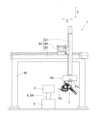
図1に示すように、地面である床に固定された架台62に直動ユニット63が設置され、直動ユニット63の出力部となる第3の直動アクチュエータ67のガイド(第3の摺動部)67bに、回転ユニットRuが取り付けられている。回転ユニットRuは、回転アクチュエータRaとリンク作動装置7とを備える。回転アクチュエータRaの回転軸Caは、第3の直動アクチュエータ67のガイド67bの進退方向(この例では上下方向)に対し平行になるように配置されている。 [First embodiment]
A working device combining a rotary unit and a linear motion unit will be described with reference to Figs.
<General structure of working device>
1, a
図2に示すように、特にこのリンク作動装置7は、回転アクチュエータRaの回転軸Caに対して、リンク作動装置7における基端側のリンクハブ(後述する)12の中心軸QAと、回転アクチュエータRaの回転軸Caとが角度θtを成すように、回転アクチュエータRaの出力部Raaに、取付部材3およびスペーサ4を介して取り付けられている。前記角度θtを取付角度θtと言う場合がある。 2, in particular, the
図1に示すように、被作業体であるワーク2は、コンベア等の搬送機器5によりワーク設置台8に載置されて搬送される。ワーク設置台8にワーク2を載置するのではなく、作業工程にきたらワーク昇降装置8Aにてワーク2を搬送機器5から持ち上げてもよい。また、搬送機器5でワーク2を搬送するのではなく、ワーク設置台8に作業者または他のロボットがワーク2を載置してもよい。
作業装置1は、リンク作動装置7の先端部材40に取り付けられたエンドエフェクタEeを、ワーク2に対し位置決めして作業を行う。回転ユニットRuと直動ユニット63は、例えば、同じコントローラに接続され、このコントローラにより同期制御する構成である。なお回転ユニットRuと直動ユニット63を非同期で制御する構成にしてもよい。 1, a
The working
<リンク作動装置について>
図3および図4に示すように、リンク作動装置7は、パラレルリンク機構9と、このパラレルリンク機構9を作動させる姿勢制御用アクチュエータ10とを備える。
<パラレルリンク機構>
パラレルリンク機構9は、基端側のリンクハブ12に対し先端側のリンクハブ13を3組のリンク機構14を介して姿勢変更可能に連結したものである。リンク機構14の組数は4組以上であってもよい。なお図4では、1組のリンク機構14のみが示され、残りの2つのリンク機構が省略されている。 <About the link actuator>
As shown in FIGS. 3 and 4 , the
<Parallel link mechanism>
The
各リンク機構14は、基端側の端部リンク部材15、先端側の端部リンク部材16、および中央リンク部材17を有し、4つの回転対偶からなる4節連鎖のリンク機構をなす。
基端側および先端側の端部リンク部材15,16はL字形状であり、一端がそれぞれ基端側のリンクハブ12および先端側のリンクハブ13に回転可能に連結されている。中央リンク部材17は、両端に基端側および先端側の端部リンク部材15,16の他端がそれぞれ回転可能に連結されている。 Each
The base end and tip
パラレルリンク機構9は、2つの球面リンク機構を組み合わせた構造である。基端側のリンクハブ12と基端側の端部リンク部材15の各回転対偶、および基端側の端部リンク部材15と中央リンク部材17の各回転対偶の中心軸が、基端側の球面リンク中心PAで交差している。同様に、先端側のリンクハブ13と先端側の端部リンク部材16の各回転対偶、および先端側の端部リンク部材16と中央リンク部材17の各回転対偶の中心軸が、先端側の球面リンク中心PBで交差している。The
また、基端側のリンクハブ12と基端側の端部リンク部材15との回転対偶の中心と基端側の球面リンク中心PA間の距離は同じである。基端側の端部リンク部材15と中央リンク部材17との回転対偶の中心と基端側の球面リンク中心PA間の距離は同じである。同様に、先端側のリンクハブ13と先端側の端部リンク部材16との回転対偶の中心と先端側の球面リンク中心PB間の距離は同じである。先端側の端部リンク部材16と中央リンク部材17との回転対偶の中心と先端側の球面リンク中心PB間の距離は同じである。基端側および先端側の端部リンク部材15,16と中央リンク部材17との各回転対偶の中心軸は、ある交差角γを持っていてもよいし、平行であってもよい。The distance between the center of the rotational joint between the base
図5に、基端側のリンクハブ12と基端側の端部リンク部材15の各回転対偶の中心軸O1と、球面リンク中心PAとの関係が示されている。先端側のリンクハブ13(図4)および先端側の端部リンク部材16(図4)の形状ならびに位置関係も、図示しないが図5と同様である。図5では、基端側のリンクハブ12と基端側の端部リンク部材15との各回転対偶の中心軸O1と、基端側の端部リンク部材15と中央リンク部材17との各回転対偶の中心軸O2とが成す角度αが90°となっている。但し、前記角度αは90°以外であってもよい。Figure 5 shows the relationship between the central axis O1 of each rotation pair between the base
3組のリンク機構14は、幾何学的に同一形状をなす。幾何学的に同一形状とは、図6に示すように、各リンク部材15,16,17を直線で表現した幾何学モデル、すなわち各回転対偶と、これら回転対偶間を結ぶ直線とで表現したモデルが、どのような姿勢をとっていても、中央リンク部材17の中央部に対する基端側部分と先端側部分が対称を成す形状であることを言う。図6は、1組のリンク機構14を直線で表現した図である。この実施形態のパラレルリンク機構9は回転対称タイプで、基端側のリンクハブ12および基端側の端部リンク部材15と、先端側のリンクハブ13および先端側の端部リンク部材16との位置関係が、中央リンク部材17の中心線Cに対して回転対称となる位置構成になっている。各中央リンク部材17の中央部は、共通の軌道円D上に位置している。The three
基端側のリンクハブ12と先端側のリンクハブ13と3組のリンク機構14とで、基端側のリンクハブ12に対し先端側のリンクハブ13が直交2軸周りに回転自在な2自由度機構が構成されている。言い換えると、基端側のリンクハブ12に対して先端側のリンクハブ13を、回転が2自由度で姿勢変更自在な機構としている。この2自由度機構は、コンパクトでありながら、基端側のリンクハブ12に対する先端側のリンクハブ13の可動範囲を広くとれる。The base
例えば、基端側および先端側の球面リンク中心PA,PBを通り、基端側および先端側のリンクハブ12,13と基端側および先端側の端部リンク部材15,16の各回転対偶の中心軸O1(図5)と直角に交わる直線を基端側および先端側のリンクハブ12,13の中心軸QA,QBとした場合、基端側のリンクハブ12の中心軸QAと先端側のリンクハブ13の中心軸QBとの折れ角θの最大値である最大折れ角θmaxを約±90°とすることができる。また、基端側のリンクハブ12に対する先端側のリンクハブ13の旋回角φを0°~360°の範囲に設定できる。折れ角θは、基端側のリンクハブ12の中心軸QAに対して先端側のリンクハブ13の中心軸QBが傾斜した垂直角度のことである。一方、旋回角φは、基端側のリンクハブ12の中心軸QAに対して先端側のリンクハブ13の中心軸QBが傾斜した水平角度のことである。なお最大折れ角θmaxが90°以上であってよい。 For example, if the central axes QA and QB of the base-side and tip-
基端側のリンクハブ12に対する先端側のリンクハブ13の姿勢変更は、基端側のリンクハブ12の中心軸QAと先端側のリンクハブ13の中心軸QBとの交点Oを回転中心として行われる。図7の実線は、基端側のリンクハブ12の中心軸QAと先端側のリンクハブ13の中心軸QBが同一線上にある状態を示し、図7の二点鎖線は、基端側のリンクハブ12の中心軸QAに対して先端側のリンクハブ13の中心軸QBが或る作動角(折れ角)をとった状態を示す。図6に示すように、基端側のリンクハブ12に対する先端側のリンクハブ13の姿勢が変化しても、基端側と先端側の球面リンク中心PA,PB間の距離Lは変化しない。The change in the position of the tip
図5および図6に示すように、このパラレルリンク機構9において、以下の各条件を全て満たすとき、幾何学的対称性から基端側のリンクハブ12および基端側の端部リンク部材15と、先端側のリンクハブ13および先端側の端部リンク部材16とは同じに動く。よって、パラレルリンク機構9は、基端側から先端側へ回転伝達を行う場合、基端側と先端側は同じ回転角になって等速で回転する等速自在継手として機能する。As shown in Figures 5 and 6, when all of the following conditions are met in this
条件1:各リンク機構14における基端側および先端側のリンクハブ12,13と基端側および先端側の端部リンク部材15,16の回転対偶の中心軸O1の角度および基端側および先端側の球面リンク中心PA,PBからの長さが互いに等しい。
条件2:各リンク機構14の基端側および先端側のリンクハブ12,13と基端側および先端側の端部リンク部材15,16の回転対偶の中心軸O1、および基端側および先端側の端部リンク部材15,16と中央リンク部材17の回転対偶の中心軸O2が、基端側および先端側において基端側および先端側の球面リンク中心PA,PBと交差する。
条件3:基端側の端部リンク部材15と先端側の端部リンク部材16の幾何学的形状が等しい。
条件4:中央リンク部材17における基端側部分と先端側部分の幾何学的形状が等しい。
条件5:中央リンク部材17の対称面に対して、中央リンク部材17と基端側および先端側の端部リンク部材15,16との角度位置関係が基端側と先端側とで同じである。 Condition 1: The angle of the central axis O1 of the rotational pair between the base end and tip
Condition 2: The central axis O1 of the rotational pair between the base end and tip
Condition 3: The geometric shapes of the base
Condition 4: The geometric shapes of the base end portion and the tip end portion of the
Condition 5: The angular positional relationship between the
図3および図4に示すように、基端側のリンクハブ12は、平板状の基端部材6と、この基端部材6と一体に設けられた3個の回転軸連結部材21とを有する。図5に示すように、基端部材6は中央部に円形の貫通孔6aを有し、この貫通孔6aの周囲に3個の回転軸連結部材21が円周方向に等間隔で配置されている。図4および図5に示すように、貫通孔6aの中心は、基端側のリンクハブ12の中心軸QA上に位置する。各回転軸連結部材21には、軸心が基端側のリンクハブ12の中心軸QAと交差する回転軸22が回転自在に連結されている。この回転軸22に、基端側の端部リンク部材15の一端が連結されている。As shown in Figures 3 and 4, the base
図5に示すように、回転軸22は、軸方向に沿って順次、大径部22a、小径部22b、および雄ねじ部22cを有し、小径部22bで2個の軸受23を介して回転軸連結部材21に回転自在に支持されている。軸受23は、例えば深溝玉軸受、アンギュラ玉軸受等の玉軸受である。これらの軸受23は、回転軸連結部材21に設けられた内径溝に外輪外周面が嵌合状態で設置され固定されている。他の回転対偶部に設けられる軸受の種類および設置方法も同様である。As shown in FIG. 5, the rotating
回転軸22は、大径部22aで後述の減速機構52の出力軸52aに同心軸上に配置されている。回転軸22には、この回転軸22と一体に回転するように、基端側の端部リンク部材15の一端が連結されている。基端側の端部リンク部材15の一端に切欠き部25が形成され、この切欠き部25の両側部分が内外一対の回転軸支持部26,27を構成している。これら一対の回転軸支持部26,27に貫通孔がそれぞれ形成されている。回転軸連結部材21が切欠き部25内に配置され、回転軸22の小径部22bが前記貫通孔および軸受23の内輪内周面に挿通されている。回転軸22の雄ねじ部22cは、内側の回転軸支持部27よりも内側に突出している。The
回転軸22の大径部22aの外周にスペーサ28が嵌合され、このスペーサ28を介して基端側の端部リンク部材15と減速機構52の出力軸52aとがボルト29で固定されている。さらに、回転軸22の雄ねじ部22cにナットが螺着されている。軸受23の内輪端面と一対の回転軸支持部26,27との間に、スペーサが介在されており、前記ナットの螺着時に軸受23に予圧が付与される。A
基端側の端部リンク部材15の他端には、中央リンク部材17の一端に回転自在に連結された回転軸35が連結されている。この回転軸35は、基端側のリンクハブ12の回転軸22と同様に、大径部35a、小径部35b、および雄ねじ部35cを有し、小径部35bで2個の軸受36を介して中央リンク部材17の一端に回転自在に支持されている。基端側の端部リンク部材15の他端に切欠き部37が形成され、この切欠き部37の両側部分が内外一対の回転軸支持部38,39を構成している。これら回転軸支持部38,39に貫通孔がそれぞれ形成されている。雄ねじ部35cは、内側の回転軸支持部39よりも内側に突出している。The other end of the base-side
切欠き部37内に中央リンク部材17の一端が配置され、前記小径部35bが前記貫通孔および軸受36の内輪内周面に挿通されている。さらに、雄ねじ部35cにナットが螺着されている。軸受36の内輪端面と一対の回転軸支持部38,39との間に、スペーサが介在されており、前記ナットの螺着時に軸受36に予圧が付与される。One end of the
図3および図7に示すように、先端側のリンクハブ13は、平板状の先端部材40と、この先端部材40の底面に円周方向等配で設けられた3個の回転軸連結部材41とを有する。各回転軸連結部材41が配置される円周の中心は、先端側のリンクハブ13の中心軸QB上に位置する。各回転軸連結部材41には、軸心が先端側のリンクハブ13の中心軸QBと交差する回転軸43が回転自在に連結されている。この回転軸43に、先端側の端部リンク部材16の一端が連結されている。先端側の端部リンク部材16の他端には、中央リンク部材17の他端に回転自在に連結された回転軸45が連結されている。As shown in Figures 3 and 7, the tip-
先端側のリンクハブ13の回転軸43および中央リンク部材17の回転軸45も、前記回転軸35と同じ形状であり、かつ2個の軸受(図示せず)を介して回転軸連結部材41および中央リンク部材17の他端にそれぞれ回転自在に連結されている。The rotating
<姿勢制御用アクチュエータ>
図3および図5に示すように、姿勢制御用アクチュエータ10は、減速機構52を備えたロータリアクチュエータであり、基端側のリンクハブ12の基端部材6の下面に前記回転軸22と同軸上に設置されている。姿勢制御用アクチュエータ10と減速機構52は一体に設けられ、モータ固定部材53により減速機構52が基端部材6に固定されている。なお、姿勢制御用アクチュエータ10は、ブレーキ付きのものを使用してもよい。 <Attitude control actuator>
3 and 5, the
この例では、3組のリンク機構14のすべてに姿勢制御用アクチュエータ10が設けられているが、3組のリンク機構14のうち少なくとも2組に姿勢制御用アクチュエータ10を設ければ、基端側のリンクハブ12に対する先端側のリンクハブ13の姿勢を確定することができる。
3つの姿勢制御用アクチュエータ10は、それらの回転軸22が基端側リンクハブ12の中心軸QA(図4)と直交するように配置され、これらの姿勢制御用アクチュエータ10の回転軸22の交点である中央位置P10が、前記角度θt(図2)を成す基端側のリンクハブ12の中心軸QA(図4)上にある。また3つの姿勢制御用アクチュエータ10のうち2つの姿勢制御用アクチュエータ10の回転軸22の二等分線22Lが、回転アクチュエータRaの回転軸Caと基端側のリンクハブ12の中心軸QAが成す平面上にある。前記二等分線22Lは、「回転軸22」の軸心に直交し、且つ、「回転軸22」の大径部22aの基端部と雄ねじ部22cの先端部との長手方向中間部を通る線である。さらに、回転アクチュエータRaの回転軸Caと基端側のリンクハブ12の中心軸QAが成す角度の鋭角側に前記二等分線22Lが位置している。 In this example, all three
The three
図5に示すように、減速機構52はフランジ出力であって、大径の出力軸52aを有する。出力軸52aの先端面は、出力軸52aの中心線と直交する平面状のフランジ面54となっている。出力軸52aは、前記スペーサ28を介して、基端側の端部リンク部材15の回転軸支持部26にボルト29で接続されている。基端側のリンクハブ12(図4)と基端側の端部リンク部材15の回転対偶部を構成する、回転軸22の大径部22aが、減速機構52の出力軸52aに設けられた内径溝57に嵌っている。As shown in FIG. 5, the
図4および図5に示すように、リンク作動装置7は、各姿勢制御用アクチュエータ10を回転駆動することで、パラレルリンク機構9が作動する。詳しくは、姿勢制御用アクチュエータ10を回転駆動すると、その回転が減速機構52を介して減速して回転軸22に伝達される。それにより、基端側のリンクハブ12に対する基端側の端部リンク部材15の角度が変わり、基端側のリンクハブ12に対する先端側のリンクハブ13の姿勢が任意に変更される。As shown in Figures 4 and 5, the
<回転アクチュエータ>
図1に示すように、回転アクチュエータRaは、後述する直動ユニット63の出力部に取り付けられている。図2、図8Aおよび図8Bに示すように、回転アクチュエータRaは、回転制御用のアクチュエータ本体18と、このアクチュエータ本体18の回転を減速する減速機19とを有する。この例の回転アクチュエータRaとして、アクチュエータ本体18と減速機19とが一体に設けられた減速機付きモータが適用されている。またこの例では、リンク作動装置7の基端側リンクハブ12の中心軸QAと回転アクチュエータRaの回転軸Caは、交差するように取り付けられているが、交差させずに取り付けられてもよい。 <Rotation Actuator>
As shown in Fig. 1, the rotary actuator Ra is attached to an output section of a
前記直動ユニット63の出力部(図1)に取り付けられる連結部材20に、複数本の支柱24が平行に立設されている。これら支柱24の先端部に回転アクチュエータ固定部材30が設置され、この回転アクチュエータ固定部材30に、前記減速機付きモータが固定されている。回転アクチュエータRaの出力部Raaは、この回転軸回りにθp回転する。前記θpの回転範囲は最大±180°である。 A plurality of
回転アクチュエータRaの出力部Raaである減速機19の出力軸には、ボルト等により取付部材3が固定されている。回転アクチュエータRaの前記出力軸には、取付部材3によりリンク作動装置7が角度θt傾けた状態で設置されている。具体的には、取付部材3の先端部に、回転アクチュエータRaの回転軸Caに対して所定角度で傾斜する傾斜面3aが設けられている。この傾斜面3aに対して、スペーサ4を介して、基端側リンクハブ12の基端部材6がボルト等で固定されている。 An
前記角度θtは0°より大きく90°以下(0°<θt≦90°)の角度範囲に設定される。この例では角度θtは45°であるが、前記角度範囲内の他の角度であってもよい。またリンク作動装置7における基端側のリンクハブ12の中心軸QAと、回転アクチュエータRaの回転軸Caとは交差するように取り付けられている。このような構成により、リンク作動装置7は、前記回転軸Caに対し角度θt傾いた状態で回転アクチュエータRaの回転軸周りを回転し得る。 The angleθt is set in an angle range greater than 0° and equal to or less than 90° (0°<θt ≦90°). In this example, the angleθt is 45°, but it may be another angle within the angle range. The
<エンドエフェクタ>
先端側のリンクハブ13の先端部材40には、エンドエフェクタEeが取り付けられている。エンドエフェクタEeは、例えば、グリッパを含むハンド、洗浄用ノズル、ディスペンサ、溶接トーチ、画像処理機器Eg(図14)等が挙げられる。
図14に示す画像処理機器Egは、例えば、ワーク2を撮像するカメラCr、およびワーク2を照らす照明具Le等を含む。この場合の作業装置は、リンク作動装置7に画像処理機器Egが搭載された外観検査装置1Aである。カメラCrおよび照明具Leは、配線を介してカメラ制御システム(図示せず)と繋がっており、前記カメラ制御システムにより撮影時の各種制御が行われる。 <End effector>
An end effector Ee is attached to a
14 includes, for example, a camera Cr that captures an image of the
<カバー、ケーブルベア等>
図8Aおよび図8Bに示すように、回転アクチュエータRaの周りにはカバー31が設けられている。カバー31は、それぞれ円筒状のカバー固定体32とカバー回転体33とを有し、これらカバー固定体32とカバー回転体33は、互いに同軸で且つ回転アクチュエータRaの回転軸Caに同軸に配置される。さらにカバー回転体33は、カバー固定体32よりも大径に形成され、カバー固定体32に対し相対回転可能に設けられている。
カバー固定体32は、回転アクチュエータ固定部材30にボルト等で固定される円筒部32aと、この円筒部32aの基端側部分から径方向外方に延びるフランジ部32bとを有する。回転アクチュエータ固定部材30の外周面に、円筒部32aの内周面における基端側部分が固定されている。 <Covers, cable carriers, etc.>
8A and 8B, a
The
カバー回転体33は、円筒部33aと、この円筒部33aの基端側部分から径方向内方に延びるフランジ部33bとを有する。回転アクチュエータRaの出力部Raaに取り付けた取付部材3に、円板状の回転体取付部材34が設けられている。この回転体取付部材34は回転アクチュエータRaの回転軸Caに同軸に配置されている。回転体取付部材34の外周側部に、スペーサ42を介して、カバー回転体33のフランジ部33bが設置されている。よって、カバー回転体33は、回転アクチュエータRaの出力部Raaに同期して回転する。前記フランジ部33bの内周側縁部と、カバー固定体32のフランジ部32bの外周側縁部との間には、両フランジ部33b,32bの干渉を防ぐための環状隙間δ1が設けられている。The
カバー回転体33とカバー固定体32とで囲まれる環状空間には、姿勢制御アクチュエータ10およびエンドエフェクタEe(図2)から延びるケーブルCbを保護し案内するケーブルベア44が配置されている。なお図8Bではケーブルベアが省略されている。このケーブルベア44は、回転アクチュエータRaの周りに回転方向に摺動するように設けられている。ケーブルベア44の長手方向一端部がカバー回転体33の一部に、長手方向他端部がカバー固定体32の一部に、それぞれボルト等で固定されている。これにより、ケーブルベア44はそれぞれの円筒部32a,33aおよびフランジ部32b,33bで案内される。前記ケーブルCbとしては、具体的には、姿勢制御アクチュエータ10に接続するエンコーダケーブルおよび電源ケーブル等を含む。In the annular space surrounded by the
<直動ユニット>
図1、図9および図10に示すように、直動ユニット63には、直交3軸方向に移動するXYZステージが適用されている。直動ユニット63は、第1,第2および第3の直動アクチュエータ65,66,67を有する。第1の直動アクチュエータ65はX軸方向(図1左右方向)に進退する。第2の直動アクチュエータ66は、X軸方向に直交する前後方向であるY軸方向に進退する。第3の直動アクチュエータ67は、X軸方向およびY軸方向にそれぞれ直交するZ軸方向に進退する。この例では、前記Z軸方向が上下方向となるように設定されている。 <Linear motion unit>
As shown in Figures 1, 9 and 10, the
第1,第2および第3の直動アクチュエータ65,66,67は、それぞれ駆動源であるモータ65a,66a,67aで駆動され、各モータ65a,66a,67aの回転をそれぞれ直線往復動作に変換するボールねじ等の変換機構(図示せず)を有する。第1の直動アクチュエータ65は、第1の被摺動部であるガイド65bと、第1の摺動部であるスライドテーブル65cと、モータ65aとを有する。第1の被摺動部であるガイド65bはX軸方向に沿って延びる。第2の直動アクチュエータ66は、第2の被摺動部であるガイド66bと、第2の摺動部であるスライドテーブル66cと、モータ66aとを有する。第2の被摺動部であるガイド66bはY軸方向に沿って延びる。第1,第2の直動アクチュエータ65,66は、第1,第2の摺動部であるスライドテーブル65c,66cの進退方向が互いに直交するように配置される。The first, second and third
第3の直動アクチュエータ67は、第3の被摺動部であるスライドテーブル67cと、第3の摺動部であるガイド67bと、モータ67aとを有する。第3の摺動部であるガイド67bはZ軸方向に沿って延びる。第3の直動アクチュエータ67は、第3の摺動部であるガイド67bの進退方向が、第1,第2の摺動部であるスライドテーブル65c,66cの進退方向にそれぞれ直交するように配置されている。The third
架台62に第1の直動アクチュエータ65のガイド65bが取り付けられ、X軸方向に沿って延びる前記ガイド65bに沿って進退駆動されるスライドテーブル65cに、連結固定部材68を介して、第2の直動アクチュエータ66のガイド66bが連結されている。Y軸方向に沿って延びる前記ガイド66bに沿って進退駆動されるスライドテーブル66cには、連結固定部材69を介してスライドテーブル67cが連結されている。なお第3の直動アクチュエータ67のスライドテーブル67cを、第2の直動アクチュエータ66のスライドテーブル66cに直接固定してもよい。スライドテーブル67cに対し進退駆動される第3の直動アクチュエータ67のガイド67bが直動ユニット63の出力部となる。The
この出力部となるガイド67bに、回転ユニットRuが取り付けられている。つまり前記ガイド67bの下端部に回転アクチュエータRaが取り付けられ、この回転アクチュエータRaの回転軸Caが、第3の直動アクチュエータ67の進退方向(この例では上下方向)と平行になるように取り付けられている。本構成の場合、第3の直動アクチュエータ67のガイド67bの下端部に回転ユニットRuを設置でき、第3の直動アクチュエータ67のガイド67bと回転ユニットRuが連動して動くため、回転ユニットRuの周辺の部品が少なくなり、作業領域を広くとることができる。なお、回転アクチュエータRaの回転軸Caは、第3の直動アクチュエータ67の進退方向に対し角度を成して取り付けてもよい。A rotation unit Ru is attached to the
本実施形態では、第3の直動アクチュエータ67のガイド67bの下端部に回転ユニットRuを設置しているが、第3の直動アクチュエータ67におけるガイド67bのうち、前記下端部以外の他の場所に、回転ユニットRuを設置してもよい。第1または第2の直動アクチュエータ65,66を直動ユニット63の出力部としてもよい。またガイド67bを第2のアクチュエータ66に固定して、スライドテーブル67cに回転ユニットRuを固定して動かす構成にしてもよい。この場合、前記ガイド67bが第3の被摺動部に相当し、前記スライドテーブル67cが第3の摺動部に相当する。In this embodiment, the rotation unit Ru is installed at the lower end of the
<作業装置による作業例>
図1では、エンドエフェクタEeが真横を向き、ワーク2の左側面に対して作業を行う状態を示す。このリンク作動装置7は、折れ角θ=45°、旋回角φ=0°の状態である。なお、本実施形態では、この状態での回転アクチュエータRaの回転角θpを0°とし、平面視における反時計回りを+方向と定義する。 <Examples of work using work equipment>
1 shows a state in which the end effector Ee faces straight sideways and performs work on the left side of the
図11には、ワーク2の上面に対して作業を行う状態を示す。リンク作動装置7は、折れ角θ=45°、旋回角φ=180°の状態であり、エンドエフェクタEeが真下を向いて作業を行っている。回転アクチュエータRaの回転角θpは図1の状態に対して動作なしである。
図12には、ワーク2の下面に対して作業を行う状態を示す。リンク作動装置7は、折れ角θ=90°、旋回角φ=0°の状態であり、エンドエフェクタEeが斜め上方向を向いて作業を行っている。回転アクチュエータRaの回転角θpは図1の状態に対して動作なしである。
図13には、ワーク2の右側面に対して作業を行う状態を示す。リンク作動装置7は、図1と同様に、θ=折れ角45°、旋回角φ=0°の状態であり、エンドエフェクタEeが真横を向いているが、回転アクチュエータRaが180°(回転角θp=180°)回転している。 11 shows a state where work is being performed on the upper surface of the
12 shows a state where work is being performed on the underside of the
Fig. 13 shows a state in which work is being performed on the right side surface of the
図示はしないが、ワーク2の奥側の側面に対して作業を行う場合は、図1の状態から回転アクチュエータRaを時計回りに90°(回転角θp=-90°)回転させる。ワーク2の手前側の側面に対して作業を行う場合は、図1の状態から回転アクチュエータRaを反時計回りに90°(回転角θp=90°)回転させればよい。 Although not shown, when working on the rear side of the
ここでは直方体のワーク2に対する作業例を示しているが、円筒形または複雑な形状のワークに対しても、ワーク形状に合わせて回転アクチュエータRaの回転角θpおよびリンク作動装置7の姿勢(折れ角θ、旋回角φ)を決められる。このため、どのような形状のワーク2に対しても作業を行うことができる。本実施形態では、取付角度θt=45°の例を示しているが、どのような取付角度であってもよい。X軸を第1の直動アクチュエータとして架台に固定しているが、他の軸を第1の直動アクチュエータとして架台等に固定してもよい。また、架台を地面(床)に固定しているが、天井または壁等に固定してもよい。 Here, an example of work on a
<作用効果>
以上説明した作業装置1によれば、直動ユニット63の出力部に取り付けた回転アクチュエータRaに対して、角度θtを付けてリンク作動装置7を回転させながら作業させることで、リンク作動装置7の最大折れ角θmaxが90°であってもワーク2に対して半球面方向以上からアプローチできるようになる。例えば、回転アクチュエータRaを鉛直下向きに配置して角度θtを付けてリンク作動装置7を取り付けた場合、北半球方向からだけでなく、南半球方向からもアプローチできるようになる。そのため、従来技術よりもワーク2に対する作業範囲を大きくとれ、段取り替え作業の短縮を図ることが可能となる。また回転ユニットRuがリンク作動装置7を備えているため、高速、高精度で、人の手作業のように木目細かい作業を実現できる。 <Action and effect>
According to the working
2つ以上の姿勢制御用アクチュエータ10は、それらの回転軸22が前記基端側のリンクハブ12の中心軸QAと直交するように配置され、前記2つの姿勢制御用アクチュエータ10の回転軸22の交点(中央位置P10)が、前記角度θtを成す前記基端側のリンクハブ12の中心軸QA上にある。さらに前記2つ以上の姿勢制御用アクチュエータ10のうち2つの姿勢制御用アクチュエータ10の回転軸22の二等分線22Lが、回転アクチュエータ10の回転軸22と基端側のリンクハブ12の中心軸QAが成す平面上にあり、回転アクチュエータ10の回転軸22と基端側のリンクハブ12の中心軸QAが成す角度θtの鋭角側に前記二等分線22Lが位置している。 The two or more
この構成によると、リンク作動装置を他の方向に傾けた構成よりも、リンク作動装置7の姿勢制御用アクチュエータ10と回転アクチュエータRaが干渉しにくくなり、回転アクチュエータRaとリンク作動装置7間の距離が短くなるように配置できるため、作業装置全体のコンパクト化を実現できる。また、回転アクチュエータRaの慣性モーメントが小さくなり、回転ユニットRuの軽量化にもなるため、作業装置全体の高速動作を実現できる。With this configuration, the
回転アクチュエータRaが、回転制御用のアクチュエータ本体18と減速機19とを有する構成にしたため、減速機のない回転駆動方式の回転アクチュエータよりも、回転アクチュエータRaの径方向のコンパクト化を実現できる。空きスペースである回転アクチュエータRaの周りに、回転方向に摺動するケーブルベア44を設けたことで、リンク作動装置7の姿勢制御用アクチュエータ10等に接続するケーブルCbをケーブルベア44にコンパクトに収納できる。このため、ケーブルCbの取り回しが容易になり、ケーブルCbの断線等の心配も軽減できる。Since the rotary actuator Ra is configured to have an
直動ユニット63を、架台62に取り付けられる第1の直動アクチュエータ65と、第2の直動アクチュエータ66と、直動ユニット63の出力部となる第3の直動アクチュエータ67とを有する構成にすることで、コンベア等で搬送されてくるワーク2に対して作業を行うことができるようになり、コンベアラインを変更せずに1つのユニットとして設置できるようになる。
直動ユニット63を直交3軸方向に動くように配置することで、作業装置1を直感的に操作できる。このため、操作性が向上するだけでなく、作業装置1のバランスが安定し、高速動作を実現できる。 By configuring the
By arranging the
第3の直動アクチュエータ67は、前記第3の摺動部となるガイド67bの進退方向が上下方向となるように配置し、第3の被摺動部は直動アクチュエータ67のスライドテーブル67cとしている。このため、ワーク2と、直動ユニット63における第3の摺動部との干渉を回避しやすくなり、作業装置全体のサイズをコンパクトにできる。本願発明では、ワーク2に対する作業範囲を広くとれる構成のため、特に、直動ユニット63の出力部となる第3の直動アクチュエータ67は、第3の摺動部がワーク2と接触しやすくなる。この構成のように第3の摺動部であるガイド67bを上下方向に移動させる構成であれば、ワーク2に対しガイド67bを干渉回避位置に移動させながら、直動ユニット63を様々な方向に高速に移動することができる。The third
回転アクチュエータRaは、その回転軸Caが第3の摺動部の進退方向に対し平行になるように配置されている。このため、コンベア等で搬送されてくるワーク2に対する作業が容易となる。コンベア等で搬送されてくるワークに対して作業を行う場合、ワークの上面と側面に対する作業がメインとなり、ワークの下面等に作業を行いたい場合はワークを反転させて対応する場合が多いが、本構成では、ワーク2の上面および側面だけでなく、下面側からも作業を実施できるようになり、段取り替え等も不要になる。The rotary actuator Ra is positioned so that its rotation axis Ca is parallel to the forward and backward direction of the third sliding part. This makes it easier to work on the
リンク作動装置7は、基端側のリンクハブ12の中心軸QAと、先端側のリンクハブ16の中心軸QBとの最大折れ角θmaxが90°以上であってもよい。この場合、リンク作動装置7における基端側のリンクハブ12の中心軸QAと、回転アクチュエータRaの回転軸Caとの成す角度θtが小さくても、ワーク2に対する作業範囲を大きくとれる。 In the
リンク作動装置7に画像処理機器Egが搭載された外観検査装置1Aである場合、これまで人が様々な方向から目視検査していた外観検査工程を、高速、高精度で、自動的にできるようになる。またワーク2に対して様々な方向からキズまたは打痕、部品の有無等の外観検査を実施できる。さらにカメラCrおよび照明Le等の画像処理機器Egに接続されるケーブル類をリンク作動装置7の内部空間に通すことができる場合には、前記ケーブル類の取り回しが容易になり、旋回方向動作を繰り返してもケーブル類が捩れることがなく、断線等の不具合も低減できる。When the
<他の実施形態について>
以下の説明においては、各実施の形態で先行して説明している事項に対応している部分には同一の参照符号を付し、重複する説明を略する。構成の一部のみを説明している場合、構成の他の部分は、特に記載のない限り先行して説明している形態と同様とする。同一の構成から同一の作用効果を奏する。実施の各形態で具体的に説明している部分の組合せばかりではなく、特に組合せに支障が生じなければ、実施の形態同士を部分的に組合せることも可能である。 <Other embodiments>
In the following description, parts corresponding to matters previously described in each embodiment are given the same reference symbols, and duplicated description is omitted. When only a part of the configuration is described, the other parts of the configuration are the same as the previously described embodiment unless otherwise specified. The same action and effect are achieved from the same configuration. It is possible to combine not only the parts specifically described in each embodiment, but also partially combine the embodiments, provided that there is no particular problem with the combination.
[第2の実施形態]
この実施形態に係る作業装置を図15ないし図18と共に説明する。
この作業装置1Bは、前述の実施形態(図1)に対して、リンク作動装置7の取付角度θtを45°から90°に変更した例を示す。つまりリンク作動装置7は、回転アクチュエータRaの回転軸Caに対して、基端側のリンクハブ12の中心軸QAが直交するように取り付けられている。実際には、さらにリンク作動装置7をその基端側のリンクハブ12の中心軸周りに180°回転させて取付部材3に取り付けている。 Second Embodiment
The working device according to this embodiment will be described with reference to FIGS.
This working
<リンク作動装置の姿勢>
図15:折れ角θ=0°、旋回角φ=0°、回転角θp=0°
図16:折れ角θ=90°、旋回角φ=0°、回転角θp=0°
図17:折れ角θ=90°、旋回角φ=180°、回転角θp=0
図18:折れ角θ=0°、旋回角φ=0°、回転角θp=180°
本構成によれば、最大折れ角θmaxが90°以上のリンク作動装置7を使用し、かつ、回転アクチュエータRaの回転軸Caに対して、基端側のリンクハブ12の中心軸QAが直交するように配置することで、エンドエフェクタEeを、ワーク2の様々な面に対してその面の垂線方向からアプローチさせて作業を行うことができるようになる。その他の構成は前述の図1の実施形態と同じであり、前述の実施形態と同様の作用効果を奏する。 <Posture of link actuator>
Figure 15: Bending angle θ = 0°, turning angle φ = 0°, rotation angle θp = 0°
Figure 16: Bending angle θ = 90°, turning angle φ = 0°, rotation angle θp = 0°
Figure 17: Bending angle θ = 90°, turning angle φ = 180°, rotation angle θp = 0
Figure 18: Bending angle θ = 0°, turning angle φ = 0°, rotation angle θp = 180°
According to this configuration, by using a
[第3の実施形態:作業装置1C]
図19に示すように、Z軸方向に進退する第3の直動アクチュエータ67をワーク2側に配置してもよい。この例では、第2の直動アクチュエータ66のスライドテーブル66cに、回転アクチュエータRaが取り付けられている。この回転アクチュエータRaの回転軸Caが、第3の直動アクチュエータ67の進退方向(上下方向)と平行である点は、前述の各実施形態と同じである。この場合、回転ユニットRuとこの回転ユニットRuを支持する直動アクチュエータ(この例では第2の直動アクチュエータ66)とを備えた組立品の軽量化を図れ、作業装置全体の高速動作を実現できる。また直動ユニット63の可動範囲をコンパクトに収めることが可能となり、作業装置全体のコンパクト化を実現し易くなる。 [Third embodiment: working
As shown in FIG. 19, a third
[第4の実施形態:作業装置1D]
図20に示すように、X軸、Y軸方向に進退する第1,第2の直動アクチュエータ65,66をワーク2側に設置してもよい。この例では、地面(床)に第1の直動アクチュエータ65が設置され、このスライドテーブル65cに連結固定部材68を介して第2の直動アクチュエータ66のガイド66bが固定されている。このガイド66bに沿って進退駆動されるスライドテーブル66cに、ワーク設置台8またはワーク昇降装置8Aを介してワーク2が載置される。架台62には、連結固定部材69を介して、Z軸方向に進退する第3の直動アクチュエータ67が取り付けられている。この場合、回転ユニットRuとこの回転ユニットRuを支持する直動アクチュエータ(この例では第3の直動アクチュエータ67)とを備えた組立品の軽量化を図れ、作業装置全体の高速動作を実現できる。 [Fourth embodiment: working
As shown in FIG. 20, first and second
[第5の実施形態:作業装置1E]
図21に示すように、直動ユニット63をワーク2側に配置し、架台62に回転アクチュエータRaを取り付けてもよい。この場合、回転ユニットRuを直動ユニット63とは独立して支持できるため、作業装置全体の高速動作を実現できる。 [Fifth embodiment: working
21, the
各実施形態では、回転アクチュエータとして、減速機付きモータが適用されているが、ダイレクトドライブまたは減速機の付かないサーボモータ等、その他の構成であってもよい。
回転アクチュエータの周りに設けられるカバーは、回転アクチュエータの固定部等に固定される固定式のカバーであってもよく、このカバー内にケーブルベアが配置されてもよい。
カバーなしで、単にケーブルベアが回転アクチュエータの周りに回転方向に摺動するように設けられてもよい。 In each embodiment, a motor with a reducer is used as the rotary actuator, but other configurations such as a direct drive or a servo motor without a reducer may also be used.
The cover provided around the rotary actuator may be a fixed cover that is fixed to a fixed portion of the rotary actuator, and the cable bear may be disposed inside this cover.
There may be no cover and simply the cable bearer is provided to slide rotationally around the rotary actuator.
以上、実施形態に基づいてこの発明を実施するための形態を説明したが、今回開示された実施の形態はすべての点で例示であって制限的なものではない。この発明の範囲は上記した説明ではなくて特許請求の範囲によって示され、特許請求の範囲と均等の意味および範囲内でのすべての変更が含まれることが意図される。The above describes the mode for carrying out the present invention based on the embodiment, but the embodiment disclosed herein is illustrative in all respects and is not restrictive. The scope of the present invention is indicated by the claims, not the above description, and is intended to include all modifications within the meaning and scope of the claims.
1B,1C,1D,1E…作業装置、1A…外観検査装置、7…リンク作動装置、10…姿勢制御用アクチュエータ、12…基端側のリンクハブ、13…先端側のリンクハブ、14…リンク機構、15…基端側の端部リンク部材、16…先端側の端部リンク部材、17…中央リンク部材、18…アクチュエータ本体、19…減速機、44…ケーブルベア、62…架台、63…直動ユニット、65,66,67…第1,第2,第3の直動アクチュエータ、65b…ガイド(第1の被摺動部)、65c…スライドテーブル(第1の摺動部)、66b…ガイド(第2の被摺動部)、66c…スライドテーブル(第2の摺動部)、67b…ガイド(第3の摺動部)、67c…スライドテーブル(第3の被摺動部)、Cb…ケーブル、Eg…画像処理機器、Ra…回転アクチュエータ、Ru…回転ユニット
Claims (11)
Translated fromJapanese前記回転ユニットは、リンク作動装置と回転アクチュエータとを備え、
前記リンク作動装置は、基端側のリンクハブに対し先端側のリンクハブが3組以上のリンク機構を介して姿勢を変更可能に連結され、前記各リンク機構が、それぞれ前記基端側のリンクハブおよび前記先端側のリンクハブに一端が回転可能に連結された基端側および先端側の端部リンク部材と、これら基端側および先端側の端部リンク部材の他端に両端がそれぞれ回転可能に連結された中央リンク部材とを有し、前記3組以上のリンク機構のうちの2組以上のリンク機構に、前記基端側のリンクハブに対する前記先端側のリンクハブの姿勢を任意に変更させる姿勢制御用アクチュエータが設けられ、
前記リンク作動装置は、前記回転アクチュエータの回転軸に対して、前記基端側のリンクハブの中心軸が角度θtを成すように、前記回転アクチュエータの出力部に取り付けられ、
前記直動ユニットは、出力部となる直動アクチュエータを有し、この直動アクチュエータに前記回転ユニットが取り付けられ、前記リンク作動装置の2つ以上の姿勢制御用アクチュエータは、それらの回転軸が前記基端側のリンクハブの中心軸と直交するように配置され、前記2つ以上の姿勢制御用アクチュエータの回転軸の交点が、前記角度θtを成す前記基端側のリンクハブの中心軸上にある作業装置。 A working device that combines a rotary unit and a linear motion unit,
The rotation unit includes a link actuation device and a rotation actuator.
The link actuation device has a tip side link hub connected to a base side link hub via three or more link mechanisms so that its posture can be changed, and each of the link mechanisms has base side and tip side end link members having one end rotatably connected to the base side link hub and the tip side link hub, respectively, and a central link member having both ends rotatably connected to the other ends of the base side and tip side end link members, and two or more of the three or more link mechanisms are provided with a posture control actuator that arbitrarily changes the posture of the tip side link hub relative to the base side link hub,
the link actuator is attached to the output portion of the rotary actuator such that a central axis of the base end side link hub forms an angleθt with respect to a rotation axis of the rotary actuator,
a working device in which the linear motion unit has a linear motion actuator that serves as an output section, the rotation unit is attached to this linear motionactuator, two or more attitude control actuators of the link actuation device are arranged so that their rotation axes are perpendicular to the central axis of the base-end link hub, and an intersection of the rotation axes of the two or more attitude control actuators is on the central axis of the base-end link hub that forms the angleθt.
Priority Applications (6)
| Application Number | Priority Date | Filing Date | Title |
|---|---|---|---|
| JP2020193449AJP7579119B2 (en) | 2020-11-20 | 2020-11-20 | Working Equipment |
| DE112021006054.6TDE112021006054T5 (en) | 2020-11-20 | 2021-11-10 | WORKING EQUIPMENT |
| PCT/JP2021/041293WO2022107652A1 (en) | 2020-11-20 | 2021-11-10 | Work device |
| KR1020237020019AKR20230107842A (en) | 2020-11-20 | 2021-11-10 | work device |
| CN202180078186.0ACN116547114A (en) | 2020-11-20 | 2021-11-10 | operating device |
| US18/198,365US20230286178A1 (en) | 2020-11-20 | 2023-05-17 | Work device |
Applications Claiming Priority (1)
| Application Number | Priority Date | Filing Date | Title |
|---|---|---|---|
| JP2020193449AJP7579119B2 (en) | 2020-11-20 | 2020-11-20 | Working Equipment |
Publications (2)
| Publication Number | Publication Date |
|---|---|
| JP2022082090A JP2022082090A (en) | 2022-06-01 |
| JP7579119B2true JP7579119B2 (en) | 2024-11-07 |
Family
ID=81708865
Family Applications (1)
| Application Number | Title | Priority Date | Filing Date |
|---|---|---|---|
| JP2020193449AActiveJP7579119B2 (en) | 2020-11-20 | 2020-11-20 | Working Equipment |
Country Status (6)
| Country | Link |
|---|---|
| US (1) | US20230286178A1 (en) |
| JP (1) | JP7579119B2 (en) |
| KR (1) | KR20230107842A (en) |
| CN (1) | CN116547114A (en) |
| DE (1) | DE112021006054T5 (en) |
| WO (1) | WO2022107652A1 (en) |
Families Citing this family (1)
| Publication number | Priority date | Publication date | Assignee | Title |
|---|---|---|---|---|
| CN118701436A (en)* | 2024-07-12 | 2024-09-27 | 江苏新美星包装机械股份有限公司 | Anti-rotation device for dispenser |
Citations (5)
| Publication number | Priority date | Publication date | Assignee | Title |
|---|---|---|---|---|
| JP2017193009A (en) | 2016-04-20 | 2017-10-26 | Ntn株式会社 | Actuator and double arm actuator |
| JP2018167350A (en) | 2017-03-29 | 2018-11-01 | Ntn株式会社 | Multi joint robot |
| JP2018194443A (en) | 2017-05-18 | 2018-12-06 | Ntn株式会社 | Appearance inspection device |
| JP2019049311A (en) | 2017-09-11 | 2019-03-28 | Ntn株式会社 | Working device |
| JP2019198960A (en) | 2019-08-22 | 2019-11-21 | Ntn株式会社 | Articulated robot using link operation device |
Family Cites Families (3)
| Publication number | Priority date | Publication date | Assignee | Title |
|---|---|---|---|---|
| JP2000094245A (en) | 1998-09-17 | 2000-04-04 | Fanuc Ltd | Working equipment having parallel link mechanism |
| JP2013064644A (en) | 2011-09-16 | 2013-04-11 | Nikon Corp | Shape-measuring device, shape-measuring method, system for manufacturing structures, and method for manufacturing structures |
| JP6650223B2 (en) | 2015-07-22 | 2020-02-19 | 倉敷紡績株式会社 | Article inspection method |
- 2020
- 2020-11-20JPJP2020193449Apatent/JP7579119B2/enactiveActive
- 2021
- 2021-11-10CNCN202180078186.0Apatent/CN116547114A/enactivePending
- 2021-11-10WOPCT/JP2021/041293patent/WO2022107652A1/ennot_activeCeased
- 2021-11-10DEDE112021006054.6Tpatent/DE112021006054T5/enactivePending
- 2021-11-10KRKR1020237020019Apatent/KR20230107842A/enactivePending
- 2023
- 2023-05-17USUS18/198,365patent/US20230286178A1/enactivePending
Patent Citations (5)
| Publication number | Priority date | Publication date | Assignee | Title |
|---|---|---|---|---|
| JP2017193009A (en) | 2016-04-20 | 2017-10-26 | Ntn株式会社 | Actuator and double arm actuator |
| JP2018167350A (en) | 2017-03-29 | 2018-11-01 | Ntn株式会社 | Multi joint robot |
| JP2018194443A (en) | 2017-05-18 | 2018-12-06 | Ntn株式会社 | Appearance inspection device |
| JP2019049311A (en) | 2017-09-11 | 2019-03-28 | Ntn株式会社 | Working device |
| JP2019198960A (en) | 2019-08-22 | 2019-11-21 | Ntn株式会社 | Articulated robot using link operation device |
Also Published As
| Publication number | Publication date |
|---|---|
| US20230286178A1 (en) | 2023-09-14 |
| KR20230107842A (en) | 2023-07-18 |
| CN116547114A (en) | 2023-08-04 |
| WO2022107652A1 (en) | 2022-05-27 |
| DE112021006054T5 (en) | 2023-12-28 |
| JP2022082090A (en) | 2022-06-01 |
Similar Documents
| Publication | Publication Date | Title |
|---|---|---|
| US11154994B2 (en) | Work device and dual-arm work device | |
| US11420322B2 (en) | Working device and double-arm type working device | |
| US11247329B2 (en) | Work device and dual-arm work device | |
| US11731265B2 (en) | Parallel-kinematic machine with versatile tool orientation | |
| US4683772A (en) | Hand gear train with three degrees of freedom | |
| US11130225B2 (en) | Working device and double-arm type working device | |
| JP6527782B2 (en) | Work device using parallel link mechanism | |
| JP7579119B2 (en) | Working Equipment | |
| CN113359614B (en) | Parallel robot and circular motion track interpolation method thereof | |
| JP2018069354A (en) | Linked articulated robot | |
| WO2018088446A1 (en) | Work device and double-arm-type work device | |
| JPS61168487A (en) | Mechanical wrist mechanism | |
| JPH09364U (en) | manipulator | |
| US12350824B2 (en) | Parallel-kinematic machine with versatile tool orientation | |
| JP7260987B2 (en) | Dual-arm work device | |
| JPH08323661A (en) | Automatic assembly machine | |
| US12384018B2 (en) | Parallel link mechanism and link operation device | |
| JP2019171506A (en) | Complex working device using link operation device | |
| WO2025197663A1 (en) | Work device | |
| JP2025145200A (en) | Work equipment | |
| WO2016080472A1 (en) | Work device using parallel link mechanism | |
| WO2018164091A1 (en) | Robot | |
| CN107921568A (en) | Automatic welding machine | |
| JPH04354682A (en) | Industrial robot |
Legal Events
| Date | Code | Title | Description |
|---|---|---|---|
| RD01 | Notification of change of attorney | Free format text:JAPANESE INTERMEDIATE CODE: A7421 Effective date:20210106 | |
| RD03 | Notification of appointment of power of attorney | Free format text:JAPANESE INTERMEDIATE CODE: A7423 Effective date:20210326 | |
| A621 | Written request for application examination | Free format text:JAPANESE INTERMEDIATE CODE: A621 Effective date:20231026 | |
| A131 | Notification of reasons for refusal | Free format text:JAPANESE INTERMEDIATE CODE: A131 Effective date:20240514 | |
| A521 | Request for written amendment filed | Free format text:JAPANESE INTERMEDIATE CODE: A523 Effective date:20240705 | |
| TRDD | Decision of grant or rejection written | ||
| A01 | Written decision to grant a patent or to grant a registration (utility model) | Free format text:JAPANESE INTERMEDIATE CODE: A01 Effective date:20241001 | |
| A61 | First payment of annual fees (during grant procedure) | Free format text:JAPANESE INTERMEDIATE CODE: A61 Effective date:20241025 | |
| R150 | Certificate of patent or registration of utility model | Ref document number:7579119 Country of ref document:JP Free format text:JAPANESE INTERMEDIATE CODE: R150 |