JP7577697B2 - DEVICE AND METHOD FOR TREATING HEMORRHOIDS USING SUCTION - Patent application - Google Patents
DEVICE AND METHOD FOR TREATING HEMORRHOIDS USING SUCTION - Patent applicationDownload PDFInfo
- Publication number
- JP7577697B2 JP7577697B2JP2021576918AJP2021576918AJP7577697B2JP 7577697 B2JP7577697 B2JP 7577697B2JP 2021576918 AJP2021576918 AJP 2021576918AJP 2021576918 AJP2021576918 AJP 2021576918AJP 7577697 B2JP7577697 B2JP 7577697B2
- Authority
- JP
- Japan
- Prior art keywords
- hollow member
- elongated hollow
- distal end
- plunger
- tissue
- Prior art date
- Legal status (The legal status is an assumption and is not a legal conclusion. Google has not performed a legal analysis and makes no representation as to the accuracy of the status listed.)
- Active
Links
Images


Classifications
- A—HUMAN NECESSITIES
- A61—MEDICAL OR VETERINARY SCIENCE; HYGIENE
- A61B—DIAGNOSIS; SURGERY; IDENTIFICATION
- A61B17/00—Surgical instruments, devices or methods
- A61B17/12—Surgical instruments, devices or methods for ligaturing or otherwise compressing tubular parts of the body, e.g. blood vessels or umbilical cord
- A61B17/128—Surgical instruments, devices or methods for ligaturing or otherwise compressing tubular parts of the body, e.g. blood vessels or umbilical cord for applying or removing clamps or clips
- A61B17/1285—Surgical instruments, devices or methods for ligaturing or otherwise compressing tubular parts of the body, e.g. blood vessels or umbilical cord for applying or removing clamps or clips for minimally invasive surgery
- A—HUMAN NECESSITIES
- A61—MEDICAL OR VETERINARY SCIENCE; HYGIENE
- A61B—DIAGNOSIS; SURGERY; IDENTIFICATION
- A61B18/00—Surgical instruments, devices or methods for transferring non-mechanical forms of energy to or from the body
- A61B18/04—Surgical instruments, devices or methods for transferring non-mechanical forms of energy to or from the body by heating
- A61B18/08—Surgical instruments, devices or methods for transferring non-mechanical forms of energy to or from the body by heating by means of electrically-heated probes
- A61B18/082—Probes or electrodes therefor
- A—HUMAN NECESSITIES
- A61—MEDICAL OR VETERINARY SCIENCE; HYGIENE
- A61B—DIAGNOSIS; SURGERY; IDENTIFICATION
- A61B1/00—Instruments for performing medical examinations of the interior of cavities or tubes of the body by visual or photographical inspection, e.g. endoscopes; Illuminating arrangements therefor
- A61B1/04—Instruments for performing medical examinations of the interior of cavities or tubes of the body by visual or photographical inspection, e.g. endoscopes; Illuminating arrangements therefor combined with photographic or television appliances
- A61B1/05—Instruments for performing medical examinations of the interior of cavities or tubes of the body by visual or photographical inspection, e.g. endoscopes; Illuminating arrangements therefor combined with photographic or television appliances characterised by the image sensor, e.g. camera, being in the distal end portion
- A—HUMAN NECESSITIES
- A61—MEDICAL OR VETERINARY SCIENCE; HYGIENE
- A61B—DIAGNOSIS; SURGERY; IDENTIFICATION
- A61B1/00—Instruments for performing medical examinations of the interior of cavities or tubes of the body by visual or photographical inspection, e.g. endoscopes; Illuminating arrangements therefor
- A61B1/31—Instruments for performing medical examinations of the interior of cavities or tubes of the body by visual or photographical inspection, e.g. endoscopes; Illuminating arrangements therefor for the rectum, e.g. proctoscopes, sigmoidoscopes, colonoscopes
- A—HUMAN NECESSITIES
- A61—MEDICAL OR VETERINARY SCIENCE; HYGIENE
- A61B—DIAGNOSIS; SURGERY; IDENTIFICATION
- A61B17/00—Surgical instruments, devices or methods
- A61B17/12—Surgical instruments, devices or methods for ligaturing or otherwise compressing tubular parts of the body, e.g. blood vessels or umbilical cord
- A61B17/12009—Implements for ligaturing other than by clamps or clips, e.g. using a loop with a slip knot
- A61B17/12013—Implements for ligaturing other than by clamps or clips, e.g. using a loop with a slip knot for use in minimally invasive surgery, e.g. endoscopic surgery
- A—HUMAN NECESSITIES
- A61—MEDICAL OR VETERINARY SCIENCE; HYGIENE
- A61B—DIAGNOSIS; SURGERY; IDENTIFICATION
- A61B17/00—Surgical instruments, devices or methods
- A61B17/32—Surgical cutting instruments
- A61B17/3205—Excision instruments
- A61B17/32056—Surgical snare instruments
- A—HUMAN NECESSITIES
- A61—MEDICAL OR VETERINARY SCIENCE; HYGIENE
- A61B—DIAGNOSIS; SURGERY; IDENTIFICATION
- A61B90/00—Instruments, implements or accessories specially adapted for surgery or diagnosis and not covered by any of the groups A61B1/00 - A61B50/00, e.g. for luxation treatment or for protecting wound edges
- A61B90/30—Devices for illuminating a surgical field, the devices having an interrelation with other surgical devices or with a surgical procedure
- A—HUMAN NECESSITIES
- A61—MEDICAL OR VETERINARY SCIENCE; HYGIENE
- A61B—DIAGNOSIS; SURGERY; IDENTIFICATION
- A61B1/00—Instruments for performing medical examinations of the interior of cavities or tubes of the body by visual or photographical inspection, e.g. endoscopes; Illuminating arrangements therefor
- A61B1/00064—Constructional details of the endoscope body
- A61B1/00071—Insertion part of the endoscope body
- A61B1/0008—Insertion part of the endoscope body characterised by distal tip features
- A61B1/00087—Tools
- A—HUMAN NECESSITIES
- A61—MEDICAL OR VETERINARY SCIENCE; HYGIENE
- A61B—DIAGNOSIS; SURGERY; IDENTIFICATION
- A61B1/00—Instruments for performing medical examinations of the interior of cavities or tubes of the body by visual or photographical inspection, e.g. endoscopes; Illuminating arrangements therefor
- A61B1/012—Instruments for performing medical examinations of the interior of cavities or tubes of the body by visual or photographical inspection, e.g. endoscopes; Illuminating arrangements therefor characterised by internal passages or accessories therefor
- A61B1/018—Instruments for performing medical examinations of the interior of cavities or tubes of the body by visual or photographical inspection, e.g. endoscopes; Illuminating arrangements therefor characterised by internal passages or accessories therefor for receiving instruments
- A—HUMAN NECESSITIES
- A61—MEDICAL OR VETERINARY SCIENCE; HYGIENE
- A61B—DIAGNOSIS; SURGERY; IDENTIFICATION
- A61B17/00—Surgical instruments, devices or methods
- A61B2017/0023—Surgical instruments, devices or methods disposable
- A—HUMAN NECESSITIES
- A61—MEDICAL OR VETERINARY SCIENCE; HYGIENE
- A61B—DIAGNOSIS; SURGERY; IDENTIFICATION
- A61B17/00—Surgical instruments, devices or methods
- A61B17/00234—Surgical instruments, devices or methods for minimally invasive surgery
- A61B2017/00292—Surgical instruments, devices or methods for minimally invasive surgery mounted on or guided by flexible, e.g. catheter-like, means
- A61B2017/00296—Surgical instruments, devices or methods for minimally invasive surgery mounted on or guided by flexible, e.g. catheter-like, means mounted on an endoscope
- A—HUMAN NECESSITIES
- A61—MEDICAL OR VETERINARY SCIENCE; HYGIENE
- A61B—DIAGNOSIS; SURGERY; IDENTIFICATION
- A61B17/00—Surgical instruments, devices or methods
- A61B2017/00367—Details of actuation of instruments, e.g. relations between pushing buttons, or the like, and activation of the tool, working tip, or the like
- A61B2017/00407—Ratchet means
- A—HUMAN NECESSITIES
- A61—MEDICAL OR VETERINARY SCIENCE; HYGIENE
- A61B—DIAGNOSIS; SURGERY; IDENTIFICATION
- A61B17/00—Surgical instruments, devices or methods
- A61B2017/0046—Surgical instruments, devices or methods with a releasable handle; with handle and operating part separable
- A—HUMAN NECESSITIES
- A61—MEDICAL OR VETERINARY SCIENCE; HYGIENE
- A61B—DIAGNOSIS; SURGERY; IDENTIFICATION
- A61B17/00—Surgical instruments, devices or methods
- A61B2017/00681—Aspects not otherwise provided for
- A61B2017/00734—Aspects not otherwise provided for battery operated
- A—HUMAN NECESSITIES
- A61—MEDICAL OR VETERINARY SCIENCE; HYGIENE
- A61B—DIAGNOSIS; SURGERY; IDENTIFICATION
- A61B17/00—Surgical instruments, devices or methods
- A61B2017/00743—Type of operation; Specification of treatment sites
- A61B2017/00818—Treatment of the gastro-intestinal system
- A—HUMAN NECESSITIES
- A61—MEDICAL OR VETERINARY SCIENCE; HYGIENE
- A61B—DIAGNOSIS; SURGERY; IDENTIFICATION
- A61B17/00—Surgical instruments, devices or methods
- A61B17/12—Surgical instruments, devices or methods for ligaturing or otherwise compressing tubular parts of the body, e.g. blood vessels or umbilical cord
- A61B17/12009—Implements for ligaturing other than by clamps or clips, e.g. using a loop with a slip knot
- A61B2017/12018—Elastic band ligators
- A—HUMAN NECESSITIES
- A61—MEDICAL OR VETERINARY SCIENCE; HYGIENE
- A61B—DIAGNOSIS; SURGERY; IDENTIFICATION
- A61B17/00—Surgical instruments, devices or methods
- A61B17/30—Surgical pincettes, i.e. surgical tweezers without pivotal connections
- A61B2017/306—Surgical pincettes, i.e. surgical tweezers without pivotal connections holding by means of suction
- A—HUMAN NECESSITIES
- A61—MEDICAL OR VETERINARY SCIENCE; HYGIENE
- A61B—DIAGNOSIS; SURGERY; IDENTIFICATION
- A61B18/00—Surgical instruments, devices or methods for transferring non-mechanical forms of energy to or from the body
- A61B2018/00315—Surgical instruments, devices or methods for transferring non-mechanical forms of energy to or from the body for treatment of particular body parts
- A61B2018/00345—Vascular system
- A61B2018/00404—Blood vessels other than those in or around the heart
- A61B2018/00428—Severing
- A—HUMAN NECESSITIES
- A61—MEDICAL OR VETERINARY SCIENCE; HYGIENE
- A61B—DIAGNOSIS; SURGERY; IDENTIFICATION
- A61B18/00—Surgical instruments, devices or methods for transferring non-mechanical forms of energy to or from the body
- A61B2018/00315—Surgical instruments, devices or methods for transferring non-mechanical forms of energy to or from the body for treatment of particular body parts
- A61B2018/00482—Digestive system
- A61B2018/005—Rectum
- A—HUMAN NECESSITIES
- A61—MEDICAL OR VETERINARY SCIENCE; HYGIENE
- A61B—DIAGNOSIS; SURGERY; IDENTIFICATION
- A61B18/00—Surgical instruments, devices or methods for transferring non-mechanical forms of energy to or from the body
- A61B2018/00571—Surgical instruments, devices or methods for transferring non-mechanical forms of energy to or from the body for achieving a particular surgical effect
- A61B2018/00595—Cauterization
- A—HUMAN NECESSITIES
- A61—MEDICAL OR VETERINARY SCIENCE; HYGIENE
- A61B—DIAGNOSIS; SURGERY; IDENTIFICATION
- A61B18/00—Surgical instruments, devices or methods for transferring non-mechanical forms of energy to or from the body
- A61B18/04—Surgical instruments, devices or methods for transferring non-mechanical forms of energy to or from the body by heating
- A61B18/12—Surgical instruments, devices or methods for transferring non-mechanical forms of energy to or from the body by heating by passing a current through the tissue to be heated, e.g. high-frequency current
- A61B18/14—Probes or electrodes therefor
- A61B2018/1405—Electrodes having a specific shape
- A61B2018/1407—Loop
- A61B2018/141—Snare
- A—HUMAN NECESSITIES
- A61—MEDICAL OR VETERINARY SCIENCE; HYGIENE
- A61B—DIAGNOSIS; SURGERY; IDENTIFICATION
- A61B90/00—Instruments, implements or accessories specially adapted for surgery or diagnosis and not covered by any of the groups A61B1/00 - A61B50/00, e.g. for luxation treatment or for protecting wound edges
- A61B90/36—Image-producing devices or illumination devices not otherwise provided for
- A61B90/361—Image-producing devices, e.g. surgical cameras
Landscapes
- Health & Medical Sciences (AREA)
- Life Sciences & Earth Sciences (AREA)
- Surgery (AREA)
- Engineering & Computer Science (AREA)
- Veterinary Medicine (AREA)
- Biomedical Technology (AREA)
- Heart & Thoracic Surgery (AREA)
- Medical Informatics (AREA)
- Molecular Biology (AREA)
- Animal Behavior & Ethology (AREA)
- General Health & Medical Sciences (AREA)
- Public Health (AREA)
- Nuclear Medicine, Radiotherapy & Molecular Imaging (AREA)
- Pathology (AREA)
- Physics & Mathematics (AREA)
- Reproductive Health (AREA)
- Vascular Medicine (AREA)
- Biophysics (AREA)
- Optics & Photonics (AREA)
- Radiology & Medical Imaging (AREA)
- Oral & Maxillofacial Surgery (AREA)
- Plasma & Fusion (AREA)
- Otolaryngology (AREA)
- Surgical Instruments (AREA)
- Endoscopes (AREA)
Description
Translated fromJapanese本発明は、痔核の治療に関し、特に、組織を引き込むために吸引を引き起こすための装置及び方法に関し、さらに、組織を囲繞するための治療機構の使用に関する。The present invention relates to the treatment of hemorrhoids, and in particular to devices and methods for creating suction to retract tissue, and further to the use of a treatment mechanism to encircle the tissue.
痔核は、腫れて炎症を起こした肛門又は直腸下部周辺の静脈である。痔核は、肛門周辺の皮下に形成される外痔核又は肛門及び直腸下部の内壁に形成される内痔核であり得る。内痔核は、目視での検査及び治療が困難である。上記の事項を考慮すると、本発明の改良が有用であり得る。Hemorrhoids are swollen and inflamed veins around the anus or lower rectum. Hemorrhoids can be external, which form under the skin around the anus, or internal, which form on the inner wall of the anus and lower rectum. Internal hemorrhoids are difficult to visually inspect and treat. In view of the above, the improvements of the present invention may be useful.
本発明は、装置に関し、該装置は、ハンドルを含み、該ハンドルは、遠位部と組み合わされる引き金を含み、該遠位部は、組織を受け入れるための剛性長尺状の中空部材と、プランジャとを備え、該プランジャは、中空部材に取り付けられるとともに、プランジャが中空部材の内部を近位に移動する際に中空部材の遠位端において吸引を引き起こすために中空部材の内部を長手方向に摺動するように構成される。引き金を引くとプランジャが中空部材に対して近位に摺動し、中空部材の遠位端の中に組織を引き込むための吸引を発生させるように、引き金はプランジャにヒンジ式に結合される。装置は、中空部材の遠位端において受け入れられた組織を囲繞するための組織治療機構をさらに含む。The present invention relates to a device including a handle including a trigger coupled to a distal portion, the distal portion including a rigid elongated hollow member for receiving tissue, and a plunger configured to be attached to the hollow member and slide longitudinally within the hollow member to create suction at the distal end of the hollow member as the plunger moves proximally therethrough. The trigger is hingedly coupled to the plunger such that squeezing the trigger causes the plunger to slide proximally relative to the hollow member, creating suction to draw tissue into the distal end of the hollow member. The device further includes a tissue treatment mechanism for surrounding tissue received at the distal end of the hollow member.
一実施態様は、ハンドルから延びる光学ポートと、装置の遠位領域を可視化するためにプランジャの遠位面に配置された光学レンズとをさらに備え、光学レンズは光学ポートに接続される。One embodiment further includes an optical port extending from the handle and an optical lens disposed on the distal face of the plunger for visualizing a distal region of the device, the optical lens being connected to the optical port.
一実施態様は、光学レンズを介して遠位領域を見るための光学カメラをさらに備え、該光学カメラは、内視鏡機器に取り付けるために光学ポートに接続される。
一実施態様において、遠位部はロックタブを備えるとともに、ハンドル内の対応するロックスロットを介してハンドルに取り付け可能である。 One embodiment further comprises an optical camera for viewing the distal region through an optical lens, the optical camera being connected to the optical port for attachment to an endoscopic instrument.
In one embodiment, the distal portion includes a locking tab and is attachable to the handle via a corresponding locking slot in the handle.
一実施態様において、遠位部はハンドルと一体形成されている。
一実施態様において、組織治療機構は、長尺状の中空部材の遠位端内に受け入れられた組織の周りを締め付けるために結紮バンドを長尺状の中空部材の遠位端から放つための結紮バンド展開機構を備える。 In one embodiment, the distal portion is integrally formed with the handle.
In one embodiment, the tissue treatment mechanism comprises a ligating band deployment mechanism for expelling a ligating band from the distal end of the elongated hollow member for tightening around tissue received within the distal end of the elongated hollow member.
一実施態様において、結紮バンド展開機構は、中空部材の外側に長手方向に延びる部分を有するキャリアストリングを備え、且つ、中空部材及びストリングの周りに装填される結紮バンドを有する。In one embodiment, the ligation band deployment mechanism includes a carrier string having a portion that extends longitudinally outside the hollow member, and a ligation band that is loaded around the hollow member and the string.
一実施態様において、キャリアストリングの、中空部材の外側にある部分は、結紮バンド展開機構が作動されると遠位に移動し、キャリアストリングの動きにより、装填された結紮バンドを中空部材の遠位端に移動させる。In one embodiment, the portion of the carrier string that is outside the hollow member moves distally when the ligation band deployment mechanism is actuated, and movement of the carrier string moves the loaded ligation band to the distal end of the hollow member.
一実施態様において、結紮バンド展開機構は、キャリアストリングを遠位に移動させるために、ラチェット、歯車、又はプーリのうちの1つを含む。
一実施態様において、組織治療機構は、長尺状の中空部材の遠位端内に受け入れられた組織をスネアが切断するように、長尺状の中空部材の遠位端からスネアを作動可能にするためのスネア機構を備える。 In one embodiment, the ligation band deployment mechanism includes one of a ratchet, gears, or pulleys to move the carrier string distally.
In one embodiment, the tissue treatment mechanism includes a snare mechanism for actuating a snare from the distal end of the elongated hollow member such that the snare cuts tissue received within the distal end of the elongated hollow member.
一実施態様において、スネアは通電される。
本発明はまた方法に関し、該方法は装置の剛性長尺状の中空部材の遠位端をキャビティに挿入することを含み、該装置はプランジャを有し、該プランジャは、中空部材に取り付けられ、且つ、当該プランジャが中空部材の内部を近位に移動する際に中空部材の遠位端において吸引を引き起こすために中空部材の内部を長手方向に摺動するように構成される。本方法は、プランジャが中空部材に対して相対的に近位に摺動し、中空部材の遠位端に組織を引き込むための吸引を発生させるように、プランジャにヒンジ式に結合される引き金を引くことをさらに備える。本方法は、中空部材の遠位端において受け入れられた組織を囲繞するために組織治療機構を作動させることをさらに備える。 In one embodiment, the snare is energized.
The invention also relates to a method, the method including inserting a distal end of a rigid elongate hollow member of a device into a cavity, the device having a plunger attached to the hollow member and configured to slide longitudinally within the hollow member to create suction at the distal end of the hollow member as the plunger moves proximally within the hollow member. The method further includes depressing a trigger hingedly coupled to the plunger to cause the plunger to slide proximally relative to the hollow member and generate suction to draw tissue into the distal end of the hollow member. The method further includes actuating a tissue treatment mechanism to surround the tissue received at the distal end of the hollow member.
本発明はさらに装置に関し、本装置は、中空ハウジングを含み、該中空ハウジングは、引き金と、観察ポートと、開放遠位端を通して組織を受け入れるための剛性長尺状遠位部とを含む。本装置は、開放遠位端において吸引を引き起こすためにハウジングの近位端に配置されたプランジャをさらに備え、観察ポートは、中空ハウジングを通して遠位に遠位部の外を可視化することを可能にする。引き金は、開放遠位端から結紮バンドを放ち、受け入れられた組織の周りを締め付けるために結紮バンド展開機構を作動させる。The present invention further relates to an apparatus including a hollow housing including a trigger, a viewing port, and a rigid elongated distal portion for receiving tissue through an open distal end. The apparatus further includes a plunger disposed at a proximal end of the housing for creating suction at the open distal end, the viewing port allowing visualization distally through the hollow housing and out of the distal portion. The trigger actuates a ligation band deployment mechanism to release a ligation band from the open distal end and tighten around the received tissue.
さらに、本発明は、装置に関し、本装置は、組織を受け入れるための開放遠位端を有する剛性中空長尺状部材と、開放遠位端において吸引を引き起こすためにハウジングの近位端に配置されたプランジャとを含む。本装置は、スライドをさらに備え、該スライドは、中空長尺状部材の外側にわたって摺動するように構成されるとともに、開放遠位端から結紮バンドを押し放ち、受け入れられた組織の周りを締め付けるように構成される。The present invention further relates to an apparatus including a rigid hollow elongate member having an open distal end for receiving tissue and a plunger disposed at a proximal end of a housing for creating suction at the open distal end. The apparatus further includes a slide configured to slide over the exterior of the hollow elongate member and configured to push a ligation band out of the open distal end and tighten around the received tissue.
本発明は、同様の要素が同じ参照番号で参照される以下の説明及び添付の図面を参照するとさらに理解することができる。本発明の例示的な実施形態は、痔核を治療するための部分的に又は全体的に使い捨ての装置を説明する。各装置は、真空を引き、装置の管状部内に痔核を受け入れるための機構を含む。本明細書に記載される特定の実施形態は、痔核の基部に結紮バンドを適用するための結紮装置であり、本明細書に記載される他の実施形態は、痔核組織を除去するためのスネア装置である。近位及び遠位という用語は、本明細書で使用する場合、装置の使用者に向かう方向(近位)及び装置の使用者から遠ざかる方向(遠位)を指すものであることに留意されたい。The present invention may be further understood with reference to the following description and accompanying drawings, in which like elements are referred to by the same reference numerals. Exemplary embodiments of the present invention describe partially or wholly disposable devices for treating hemorrhoids. Each device includes a mechanism for drawing a vacuum and receiving a hemorrhoid within a tubular portion of the device. A particular embodiment described herein is a ligation device for applying a ligation band to the base of a hemorrhoid, and another embodiment described herein is a snare device for removing hemorrhoidal tissue. It should be noted that the terms proximal and distal, as used herein, refer to directions toward (proximal) and away from (distal) a user of the device.
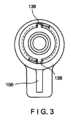
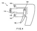
図1~図5に示されるように、痔核を結紮するための装置100は、引き金106を支持する本体104を含む近位ハンドル部分102を含む。引き金106は、ヒンジ式機構108、例えば、図4に示されるようなヒンジを介してプランジャ110に結合される。引き金の作動により、ヒンジ式機構108がプランジャ110を長手方向に(近位に及び遠位に)移動させる。この実施形態の近位部102は、使い捨て遠位部130に取り付けるように構成された再利用可能部分である。近位部102は、使い捨て遠位部130から半径方向に延びる対応するロックタブ136を受け入れるための大きさ及び形状に作られた2つのロックスロット122を有する。この実施形態のロックタブ136は矩形(矩形のロックスロット122に対応する)であるが、対応する形状のスロット122に挿入するための任意の異なる形状を有してもよい。ロックタブ136は、スロット122内にスナップ止めすることにより又は図3に示されるようにスロット122へと回転させることによりロックスロット122に係合する。ハンドル部分102は、例えば結紮処置を可視化するための内視鏡タワー(図示せず)などのビジョンシステムに接続された、例えば光ケーブル又は電気ケーブルなどの電子機器及び/又は観察機器を取り付けるためのポート120を本体104の近位端にさらに含む。As shown in FIGS. 1-5, a
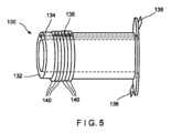
使い捨て遠位部130は、結紮処置中に痔核を受け入れるための中空管132を備える。中空管132は、ハンドル104と接続するために半径方向外側に延びるロックタブ136を有するフランジを近位端に含み得る。使い捨て遠位部130が再利用可能な近位部102に取り付けられると、プランジャ110は、プランジャ110の近位端がヒンジ式機構108に取り付けられた状態で、中空管132の内部に存在する。当業者には理解されるように、プランジャ110の遠位端112は、プランジャ110が管132内を近位に移動すると中空管132に標的組織を引き込む吸引が生成されるように、中空管132の内径に対応するような大きさ及び形状に作られた断面を有する。引き金106の作動により、プランジャ110が最初の遠位位置から近位に移動し、管132内に部分真空を引き、中空管132に痔核組織を引き込む。プランジャ110を遠位位置へと遠位に移動させると、真空が解放され、周囲組織からの装置の分離を容易にする。The disposable
管132は、痔核の基部が管132の遠位端のすぐ遠位に露出するように、痔核を捕捉するような大きさに作られている。プランジャ110は、プランジャ110の遠位端に光学レンズ114を含む。光学レンズ114は、遠位に且つ管132の遠位端から外に面する。この実施形態のプランジャ110は、光学レンズ114の近位に配置され、ポート120を通し、適切な配線を介してビジョンシステムの追加の構成要素に接続されたカメラ116を含む。この実施形態の装置100は、カメラ116に取り付けられた光源118を含む。装置100が肛門のキャビティ又は直腸内の標的組織の一部に向けられたときにカメラ116がビジョンシステムに標的組織の画像を提供するように、光源118は、カメラ116の視野内の標的領域を照明するために遠位に向けられている。その後、医師は、示されるようなカメラ116及びビジョンシステムによって、例えば内視鏡タワー(図示せず)のディスプレイ上に提供された像を使用して処置をガイドすることができる。The
装置100の第2の態様は、管132の遠位端から結紮バンド140を放つためのバンド展開機構である。医療処置で展開するために、任意の数の結紮バンド140が装置100上に予め装填されていてもよく、バンド140は中空管132の遠位端上に拡張した形態で配置する。バンド展開機構は、プランジャ110を管132内で近位に及び遠位に引くためのヒンジ式機構108とは別個のものである。バンド展開機構は、当該技術分野で周知の様々な機構のいずれかであってもよい。一実施形態では、バンド展開機構は、図5に示されるように、1つ以上の結紮バンド140がその上に装填されたバンドキャリアストリング138を含む。この実施形態のキャリアストリング138は、管132の壁内に長手方向に延びるストリングチャネル134内に延び、チャネル134の遠位端を出て、管132の遠位端の周りにループを作り、近位に再び延びて、管132の外側周囲に伸ばされた結紮バンド140に係合する。A second aspect of the
ストリング138の近位端は、ハンドル部分102と使い捨て部分130とが係合すると、再利用可能なハンドル部分102に取り付けられるように構成され得、これにより、当業者に理解されるように、ストリング138がチャネル134を通して近位に引かれることができ、次いで、管132の外側のストリング138の部分が管132の外側上で遠位に引かれ、管132から1つの結紮バンド140を放ち、管132に引き込まれた組織の周りを締め付けるようになる。バンド140が管132から放たれると、バンドはより小さな直径に収縮し、それにより選択された組織の周りを締め付けることができる。The proximal end of the
当業者が理解するように、ストリング138は、ストリング138を近位に引くことにより結紮バンド140が管132上で遠位に引かれ、結紮バンド140が所望のとおりに1つずつ展開され得るように、管132上に装填された結紮バンド140に対し、巻き付けられ得る、あるいは、他の手法で係合し得る。別の実施形態において、ストリング138は、ストリング138が近位に移動する際に結紮バンド140を押すビーズ付き部分を有してもよい。いずれの実施形態においても、ストリング138の近位の動きにより、結紮バンド140のうちの1つ以上を管132の遠位端に最終的に移動させ、バンド140を管132のすぐ遠位に放つ。当業者には理解されるように、痔核組織が管132に引き込まれると、バンド140を放つことにより、バンド140が組織の露出部を締め付けることが可能になる。As will be appreciated by those skilled in the art, the
装置100の近位ハンドル部分102は、ストリング138に取り付けられ得るバンド展開機構の要素を含む。一実施形態では、ストリング138は、ストリング138が制御された刻みで1つの方向にのみ移動し、バンド140を展開することを可能にするラチェット機構によって引かれる。別の実施形態において、バンド展開機構は、歯車又はプーリを含み得る。バンド展開機構は、例えば、ボタンが押される度にストリング138を所定の距離引っ張るハンドル102の外側のボタンによって作動されてもよい。しかしながら、バンド展開機構のアクチュエータの他の実装形態が使用されてもよい。The
結紮処置は、最初に、再利用可能なハンドル部分102を使い捨て遠位部130に繋げることによって実施される。ストリング138は、ロックタブ136をロックスロット122に挿入し、その中でロックする前に、ハンドル102内のバンド展開機構の要素に取り付けられる。装置100の第1の(非作動)構成において、プランジャ110は、中空管132の遠位端の方に配置されている。第2の構成に進むために、引き金106が作動され、ヒンジ式機構108がプランジャ110を管132の近位端に向かって引き、部分真空を生成する。装置100が結紮処置で使用され、管132の遠位端が組織の標的部分(例えば、標的痔核)に隣接して配置されると、引き金のストロークによって引かれた真空が痔核を管132に引き込む。真空が引かれた後、バンド展開機構が管132に引き込まれた痔核の基部の周りに結紮バンド140を適用開始することができる。The ligation procedure is performed by first tethering the
バンド140の適用後、装置100は、ピストンを遠位に移動させ、吸引を解放し、バンドが付けられた痔核を管132から解放することを可能にする第1の構成に戻ることができる。医師は、カメラ116を使用して、装置100を第2の痔核の隣に位置変更し、第2の痔核を管132に引き込むためにピストン110を(引き金106によって)近位に引いてもよい。その後、このプロセスは、第2のバンド140(放たれたばかりのバンドのすぐ近位に予め配置されたバンド140)を第2の痔核の基部の周りに放つために繰り返されてもよい。結紮処置は、結紮バンド140が全て展開されるまで又は全ての標的痔核が治療されるまで繰り返されてもよく、その後、医師は患者から装置100を取り除くことができる。その後、近位部が次に使用のために滅菌される一方で、遠位部130は、近位ハンドル部分102から取り外され、廃棄され得る。After application of the
図6に示されるように、第2の実施形態において、痔核を結紮するための装置200は、ハンドルとしての役割を果たすハウジング204を備えるとともに、遠位中空管部232を含む。装置200は、装置100の構成要素に類似する、プランジャ210に結合されたヒンジ式作動機構208を有する単一の使い捨て装置である。プランジャ210は、装置100のものに類似するカメラ及びレンズ構成を含み、遠位に面するレンズ114を介して使用者が管232内の処置を可視化できるようにカメラ116が画像を提供することを可能にするとともに、内視鏡ポート120を介して内視鏡機器に結合される。装置200のバンド展開機構は、装置100のものに類似してもよい。しかしながら、装置200のバンド展開機構は、ストリング138と近位部102とを接続することを可能にする装置100の特徴を伴わずに製作されてもよい。いくつかの実施形態において、装置200は、ロック手段を介して使い捨て部分と再利用可能部分とが接続される代わりに、単一部品として製作されてもよい。As shown in FIG. 6, in a second embodiment, a device 200 for ligating hemorrhoids includes a housing 204 that serves as a handle and includes a distal hollow tube portion 232. The device 200 is a single disposable device with a hinged actuation mechanism 208 coupled to a plunger 210, similar to the components of the
別の実施形態において、プランジャ210は、光学観察ポート220に結合されており、カメラは使用されない。操作する医師は、装置200の近位端の観察ポート220を通して結紮処置を可視化することができる。観察ポート220は、プランジャ210と同心である。換言すると、観察ポート220はプランジャ210の周りに円筒状に延びる。この実施形態のプランジャ210を移動させるためのヒンジ式機構208は、観察ポート220の視軸を覆うことを避けるためにU字形を有し、且つ観察ポート220は、ヒンジ式機構208が観察ポート220内で近位及び遠位に移動することを可能にするために入れられたスロットを有する。このようにして、プランジャ210は観察ポート220内で移動可能であるとともに、プランジャの遠位端212から出る観察ポート220の通視線が維持される。プランジャ210は、プランジャ210の遠位端212に配置された光学レンズ114を含む。In another embodiment, the plunger 210 is coupled to an optical viewing port 220 and no camera is used. The operating physician can visualize the ligation procedure through the viewing port 220 at the proximal end of the device 200. The viewing port 220 is concentric with the plunger 210. In other words, the viewing port 220 extends cylindrically around the plunger 210. The hinged mechanism 208 for moving the plunger 210 in this embodiment has a U-shape to avoid covering the visual axis of the viewing port 220, and the viewing port 220 has slots recessed to allow the hinged mechanism 208 to move proximally and distally within the viewing port 220. In this way, the plunger 210 is movable within the viewing port 220 while maintaining a line of sight through the viewing port 220 out of the distal end 212 of the plunger. The plunger 210 includes an
医師は、装置100に関して上述したものと実質的に類似する手法で装置200によって結紮処置を実施することができる。装置200は、中空管232に引き込まれた痔核を引くために、第1の構成から第2の構成に進められる。装置200の別の実施形態を使用する場合、医師は、装置200の近位端にある観察ポート220を使用して処置を誘導する。バンド展開機構は、装置100に関して記載した上述の方法のいずれかであってもよい。装置200の全体が結紮処置の完了後に廃棄され得る。The physician can perform the ligation procedure with device 200 in a manner substantially similar to that described above with respect to
第3の実施形態において、スネア装置300は、装置200に類似する単一の使い捨て装置であり、図7に示されるように、結紮バンドの代わりにスネア340を含む。当業者には理解されるように、スネア340はスネア装置300の中空管332の遠位端の周りに配置され、痔核をその基部で切除することにより痔核組織を除去するように構成される。医師が装置200に関して記載したものと類似する手法でスネア処置を誘導できるようにするために、カメラ116或いは光学観察ポート220に類似する光学観察ポートのいずれかが装置300で使用され得る。従って、プランジャ310は、装置200に実質的に類似する手法でヒンジ式機構308を介して管332に痔核を引き込むように動作する。しかしながら、痔核の基部が管332の遠位端に当接するまで痔核が管332に引き込まれると、スネア340は作動され、痔核は、管332の遠位端に当接する部分において除去される。In a third embodiment,
別の実施形態において、スネア340は、装置300内の適切な配線を介してスネア340に結合されたアクティブコード344によって通電されてもよい。例えば、装置300は、スネア340にエネルギーを送達するために、アクティブコード344を介してエネルギー源に動作的に結合されてもよい。このようにして、ホットスネアは、痔核の大部分を除去し、傷を焼灼する。In another embodiment, the
スネア340は、プランジャ310の動きによって作動されてもよい、又は外部から作動されてもよい。例えば、ケーブル342がスネア340とヒンジ式機構308とを接続してもよい。ヒンジ/プランジャが引き戻されると、ケーブル342が引かれ得、スネア340を締め付けるように作用する。構成要素は、スネア340は、プランジャ310がその最近位位置に到達するまで締め付けないように設計されてもよい。その代わりに、ケーブル342は、装置300の外側に延び、プランジャ310と別に引かれてもよい。ホットスネアが使用される場合、スネア340は、引き金306が作動されると通電され得る。患者の解剖学的構造から装置300を取り除くことなく複数の痔核治療が可能である。スネア切除された痔核組織は、スネア処置が完了したときに除去するために、管332内に留まり得る又は装置300から落下し得る。The
第4の実施形態において、結紮装置400は、上記の実施形態に類似する、図8に示されるような、痔核を受け入れるための遠位管部412を有する本体404を含む単一の使い捨て装置である。しかしながら、装置400は、ハウジング404の近位端に配置された、医療専門家により手動で作動されるように構成されるプランジャ410を含む。プランジャ410は、装置400の外部のハンドル部分と、ハンドル部分を軸Lに沿って近位に引くと装置の内部及び管部412の遠位端に部分真空を発生させるように、軸Lの方向に沿って装置400の内部に取り付けられた内部部分とを有する。本体404は、装置400のハンドルとしての役割を果たし、操作する医師が結紮処置を観察することができるように、視軸が管部412内に延びる観察ポート420を含む。本体404は、バンド展開機構を作動させ、管部412上に装填された結紮バンド440を放つための引き金406を有する。In a fourth embodiment, the
一実施形態において、バンド展開機構は、上記の装置のバンド展開機構に類似し、ストリングが管412の外側に沿って引かれるとバンドを展開するキャリアストリングを含む。別の実施形態において、バンド展開機構は、最も遠位のバンド440を管412の遠位端から係脱するための単純なタブ又はレバーである。この別実施形態において、複数のバンド440は、装置400上に予め装填されていてもよいが、第1のバンド440が展開された後、残りのバンドは展開位置をとるために手動で遠位に進められる。In one embodiment, the band deployment mechanism is similar to the band deployment mechanism of the device described above and includes a carrier string that deploys the bands as the string is pulled along the outside of the
結紮処置中、医師は、例えば、管412の遠位端にある、標的組織を照明するためのパワーライト418を使用し、観察ポート420を通して、痔核を位置決めする。この実施形態におけるパワーライト418は、例えばバッテリー駆動式であり得る。医師は、管412の遠位端を痔核の隣に移動すると、プランジャ410(患者の外側に残ったハンドルを有する)を手動で作動し、真空を発生させ、管412に痔核を引き込むことができる。医師は、痔核を管412に引き込むと、痔核に結紮バンド440を適用するために引き金406を作動させる。その後、医師は真空を解放し、患者から装置400を取り出す。医師は、第2の結紮バンド440を管412の遠位端に手動で進め、任意の残りの痔核を治療するためにこのプロセスを繰り返してもよい。During the ligation procedure, the physician uses, for example, a
第5の実施形態において、結紮装置500は、図9に示されるように、可撓性スライド550が管512の外側の大部分に沿って配置された中空管512を含む単回使用の使い捨て装置である。図10に示されるように、プランジャ510は、管内に部分真空を引き、管512に標的組織を引き込むために、管512の近位端に配置されている。プランジャ510は、使用者が標的組織を管512に引き込むための2つの指用リング514及び親指用リング516を含み得る。可撓性スライド550の遠位端にあるプッシャ562は、管512の遠位端から管に引き込まれた標的組織の基部上に結紮バンド540を押し放つように動作可能である。スライド550の近位端は、患者の外の管512の近位部から手動で押され、管512に沿って遠位に進められ、プッシャ562を結紮バンド540に押し付ける。結紮バンドが適用されると、部分真空を解放することができ、痔核を管512から解放することができる。装置500は、更なる組織を治療するために更なる結紮バンド540を手動で再装填可能である。装置500は、観察特徴部を含まないが、処置を可視化するための肛門鏡とともに使用されてもよい。図9の断面A-Aは、可撓性スライド550の近位端の断面を示し、図9の断面B-Bは、可撓性スライド550の遠位端の断面を示す。In a fifth embodiment, the
当業者であれば、その発明の概念から逸脱することがなければ、上述の実施形態に変更を施すことができることは理解されるであろう。さらに、実施形態の1つに関連する構造的特徴及び方法は、他の実施形態に組み込むことができることは理解されたい。従って、本発明は、開示される特定の実施形態に限定されるものではなく、むしろ、修正形態も、添付の特許請求の範囲によって定義される本発明の範囲内に包含されることは理解される。上記の実施形態及び本明細書中に具体的に記載されていないその他の実施形態の組み合わせは、上記の説明を検討すると、当業者には明らかになるであろう。従って、様々な実施形態の範囲は、上記の組成物、構造、及び方法が用いられる任意の他の用途を含む。Those skilled in the art will appreciate that changes may be made to the above-described embodiments without departing from the inventive concept thereof. Furthermore, it will be appreciated that structural features and methods associated with one of the embodiments may be incorporated into other embodiments. Thus, the invention is not limited to the specific embodiments disclosed, but rather, modifications are understood to be within the scope of the invention as defined by the appended claims. Combinations of the above-described embodiments and other embodiments not specifically described herein will be apparent to those skilled in the art upon reviewing the above description. Thus, the scope of the various embodiments includes any other applications in which the above-described compositions, structures, and methods are used.
いくつかの実施形態は、「結合された(coupled)」及び「接続された(connected)」という表現をこれらの派生語とともに用いて説明されている場合がある。これらの用語は、互いの同義語として意図されるものではない。例えば、いくつかの実施形態は、2つ以上の要素が互いに直接的に物理又は電気接触していることを示すために、「接続された」及び/又は「結合された」という用語を用いて説明されている場合がある。しかしながら、「結合された」という用語は、2つ以上の要素が互いに直接接触していないが、それでもなお互いに協働する又は相互作用することも意味し得る。Some embodiments may be described using the terms "coupled" and "connected," along with their derivatives. These terms are not intended as synonyms for each other. For example, some embodiments may be described using the terms "connected" and/or "coupled" to indicate that two or more elements are in direct physical or electrical contact with each other. However, the term "coupled" can also mean that two or more elements are not in direct contact with each other, but still cooperate or interact with each other.
本明細書で使用する場合、文脈でそうでないと明確に示されない限り、単数形「a」、「an」、及び「the」は、複数形も含むことを意図する。さらに、「備える/からなる(comprises)」及び/又は「備えている/からなる(comprising)」、又は「含む(includes)」及び/又は「含む(including)」という用語は、本明細書で使用される場合、記載された特徴、領域、工程要素及び/又は構成要素の存在を明示するが、その1つ以上のその他の特徴、領域、整数、工程、操作、要素、構成要素及び/若しくは群の存在又は追加を排除するものではないことは理解されるであろう。As used herein, the singular forms "a," "an," and "the" are intended to include the plural, unless the context clearly indicates otherwise. Furthermore, it will be understood that the terms "comprises" and/or "comprising," or "includes" and/or "including," as used herein, specify the presence of a stated feature, region, step element, and/or component, but do not exclude the presence or addition of one or more other features, regions, integers, steps, operations, elements, components, and/or groups thereof.
さらに、「実質的な(substantial)」又は「実質的に(substantially)」という用語並びに「およそ(approximate)」又は「およそ(approximately)」という用語は、いくつかの実施形態においては互換的に使用され得、当業者が許容できる任意の相対的な尺度を用いて説明され得る。例えば、これらの用語は、意図した機能をなお提供する偏差を示すために、基準パラメータとの比較としての役割を果たすことができる。非限定的ではあるが、基準パラメータからの偏差は、例えば、1%未満、3%未満、5%未満、10%未満、15%未満、20%未満などの量であり得る。Additionally, the terms "substantial" or "substantially" as well as "approximate" or "approximately" may be used interchangeably in some embodiments and may be described using any relative measure acceptable to one of ordinary skill in the art. For example, these terms may serve as a comparison to a reference parameter to indicate a deviation that still provides the intended function. Without limitation, the deviation from the reference parameter may be, for example, an amount of less than 1%, less than 3%, less than 5%, less than 10%, less than 15%, less than 20%, etc.
Claims (11)
Translated fromJapanese遠位部を備え、該遠位部は、組織を受け入れるように構成された長尺状の中空部材とプランジャとを含み、該プランジャは、前記長尺状の中空部材に取り付けられるとともに当該プランジャが前記長尺状の中空部材の内部を近位に移動する際に前記長尺状の中空部材の遠位端において吸引を引き起こすために前記長尺状の中空部材の内部を長手方向に摺動するように構成され、前記引き金は、当該引き金を引くと前記プランジャが前記長尺状の中空部材に対して相対的に近位に摺動し、前記長尺状の中空部材の前記遠位端の中に前記組織を引き込むための吸引を発生させるように、前記プランジャにヒンジ式に結合され、
前記本体の近位端に光学ポートを備え、
光学レンズを備え、前記光学レンズは、本装置の遠位領域を可視化するために前記プランジャの遠位面に配置され、前記光学レンズは前記光学ポートに接続され、
組織治療機構を備え、該組織治療機構は、前記長尺状の中空部材の前記遠位端において受け入れられた前記組織を囲繞する
装置。 a proximalhandle portion includinga body supporting a trigger;
a distal portion including an elongated hollow member configured to receive tissue and a plunger configured to be attached tothe elongated hollow member and slide longitudinally within the elongated hollow member to create suction at a distal end of the elongatedhollowmember as the plunger moves proximally within theelongated hollow member, and the trigger is hingedly coupled to the plunger such that, upon depression of the trigger, the plunger slidesproximally relative to theelongated hollow member to create suction to draw the tissue into the distal end of theelongated hollow member;
an optical portat a proximal end of the body;
an optical lens disposed on a distal surface of the plunger for visualizing a distal region of the device, the optical lens being connected to the optical port;
a tissue treatment mechanism surrounding the tissue received at the distal end of theelongated hollow member.
Priority Applications (1)
| Application Number | Priority Date | Filing Date | Title |
|---|---|---|---|
| JP2023166232AJP2023174712A (en) | 2019-07-16 | 2023-09-27 | Device and method for treatment of hemorrhoid using suction |
Applications Claiming Priority (3)
| Application Number | Priority Date | Filing Date | Title |
|---|---|---|---|
| US201962874536P | 2019-07-16 | 2019-07-16 | |
| US62/874,536 | 2019-07-16 | ||
| PCT/US2020/039181WO2021011159A1 (en) | 2019-07-16 | 2020-06-23 | Device and method for treatment of hemorrhoids using suction |
Related Child Applications (1)
| Application Number | Title | Priority Date | Filing Date |
|---|---|---|---|
| JP2023166232ADivisionJP2023174712A (en) | 2019-07-16 | 2023-09-27 | Device and method for treatment of hemorrhoid using suction |
Publications (2)
| Publication Number | Publication Date |
|---|---|
| JP2022539345A JP2022539345A (en) | 2022-09-08 |
| JP7577697B2true JP7577697B2 (en) | 2024-11-05 |
Family
ID=71579678
Family Applications (2)
| Application Number | Title | Priority Date | Filing Date |
|---|---|---|---|
| JP2021576918AActiveJP7577697B2 (en) | 2019-07-16 | 2020-06-23 | DEVICE AND METHOD FOR TREATING HEMORRHOIDS USING SUCTION - Patent application |
| JP2023166232APendingJP2023174712A (en) | 2019-07-16 | 2023-09-27 | Device and method for treatment of hemorrhoid using suction |
Family Applications After (1)
| Application Number | Title | Priority Date | Filing Date |
|---|---|---|---|
| JP2023166232APendingJP2023174712A (en) | 2019-07-16 | 2023-09-27 | Device and method for treatment of hemorrhoid using suction |
Country Status (7)
| Country | Link |
|---|---|
| US (2) | US12102333B2 (en) |
| EP (1) | EP3958751A1 (en) |
| JP (2) | JP7577697B2 (en) |
| CN (1) | CN113924053B (en) |
| AU (1) | AU2020313857B2 (en) |
| CA (1) | CA3141389A1 (en) |
| WO (1) | WO2021011159A1 (en) |
Citations (5)
| Publication number | Priority date | Publication date | Assignee | Title |
|---|---|---|---|---|
| JP2000511804A (en) | 1996-06-06 | 2000-09-12 | シー・アール・バード・インコーポレーテッド | Hydraulically operated multi-band ligating device |
| JP2003220067A (en) | 2002-01-30 | 2003-08-05 | Sumitomo Bakelite Co Ltd | Specimen sampling device |
| CN201067420Y (en) | 2006-11-02 | 2008-06-04 | 陈少明 | Disposable multi-set negative pressure automatic hemorrhoid covering bundling device |
| US20140058410A1 (en) | 2011-11-16 | 2014-02-27 | James Vermeersch | Ligator and method of operating and manufacturing same |
| WO2017089982A1 (en) | 2015-11-27 | 2017-06-01 | Secretary, Department Of Biotechnology | Hemorrhoid treatment device |
Family Cites Families (12)
| Publication number | Priority date | Publication date | Assignee | Title |
|---|---|---|---|---|
| DE2157911C2 (en) | 1970-12-11 | 1982-02-04 | Marc Edmond Jean van Bruxelles Hoorn | Surgical device for ligating internal structures |
| US5865361A (en)* | 1997-09-23 | 1999-02-02 | United States Surgical Corporation | Surgical stapling apparatus |
| US5961526A (en) | 1998-02-18 | 1999-10-05 | Boston Scientific Corporation | Coaxial needle and severing snare |
| US6974466B2 (en) | 2000-12-06 | 2005-12-13 | Wilson-Cook Medical Inc. | Ligating band delivery apparatus |
| JP2005087477A (en)* | 2003-09-17 | 2005-04-07 | G4G Kk | Internal hemorrhoid suction rubber band ligator |
| CA2682293C (en) | 2007-03-29 | 2014-03-11 | Wilson-Cook Medical, Inc. | Endoscopic suction device for mucosectomy |
| CN201057420Y (en) | 2007-05-11 | 2008-05-07 | 北京星光影视设备科技股份有限公司 | Small lens component of stage projector lamp |
| WO2011041069A1 (en) | 2009-09-30 | 2011-04-07 | Boston Scientific Scimed, Inc. | Ligating band dispenser device |
| WO2013130658A1 (en)* | 2012-02-27 | 2013-09-06 | Kamler Jan | Banding apparatus and method of use |
| WO2014137891A1 (en)* | 2013-03-04 | 2014-09-12 | Boston Scientific Scimed, Inc. | Ligation band dispensing cap assembly |
| US10660644B2 (en) | 2016-10-14 | 2020-05-26 | Logan Medical Devices, Inc. | Rectal band ligation device and method of operation thereof |
| JP7523812B2 (en)* | 2022-05-09 | 2024-07-29 | 株式会社山辰組 | A hose connecting member, a water supply device using the hose connecting member, and a water supply method using a water supply device using the hose connecting member. |
- 2020
- 2020-06-23CNCN202080041753.0Apatent/CN113924053B/enactiveActive
- 2020-06-23EPEP20739819.9Apatent/EP3958751A1/ennot_activeWithdrawn
- 2020-06-23AUAU2020313857Apatent/AU2020313857B2/ennot_activeCeased
- 2020-06-23WOPCT/US2020/039181patent/WO2021011159A1/ennot_activeCeased
- 2020-06-23USUS16/909,660patent/US12102333B2/enactiveActive
- 2020-06-23JPJP2021576918Apatent/JP7577697B2/enactiveActive
- 2020-06-23CACA3141389Apatent/CA3141389A1/enactivePending
- 2023
- 2023-09-27JPJP2023166232Apatent/JP2023174712A/enactivePending
- 2024
- 2024-08-29USUS18/819,448patent/US20240415523A1/enactivePending
Patent Citations (5)
| Publication number | Priority date | Publication date | Assignee | Title |
|---|---|---|---|---|
| JP2000511804A (en) | 1996-06-06 | 2000-09-12 | シー・アール・バード・インコーポレーテッド | Hydraulically operated multi-band ligating device |
| JP2003220067A (en) | 2002-01-30 | 2003-08-05 | Sumitomo Bakelite Co Ltd | Specimen sampling device |
| CN201067420Y (en) | 2006-11-02 | 2008-06-04 | 陈少明 | Disposable multi-set negative pressure automatic hemorrhoid covering bundling device |
| US20140058410A1 (en) | 2011-11-16 | 2014-02-27 | James Vermeersch | Ligator and method of operating and manufacturing same |
| WO2017089982A1 (en) | 2015-11-27 | 2017-06-01 | Secretary, Department Of Biotechnology | Hemorrhoid treatment device |
Also Published As
| Publication number | Publication date |
|---|---|
| CA3141389A1 (en) | 2021-01-21 |
| US20240415523A1 (en) | 2024-12-19 |
| EP3958751A1 (en) | 2022-03-02 |
| WO2021011159A1 (en) | 2021-01-21 |
| AU2020313857B2 (en) | 2023-10-26 |
| CN113924053A (en) | 2022-01-11 |
| US20210015489A1 (en) | 2021-01-21 |
| JP2023174712A (en) | 2023-12-08 |
| CN113924053B (en) | 2025-09-09 |
| AU2020313857A1 (en) | 2022-01-20 |
| JP2022539345A (en) | 2022-09-08 |
| US12102333B2 (en) | 2024-10-01 |
Similar Documents
| Publication | Publication Date | Title |
|---|---|---|
| JP3573751B2 (en) | Endoscopic ligation device | |
| US5814052A (en) | Surgical cauterization snare with ligating suture | |
| JP5273980B2 (en) | Endoscope ligation tool and endoscope ligation system | |
| US20100057109A1 (en) | Endoscopic suturing device | |
| CN101073487B (en) | Endoscope for cavity stabilizer | |
| US20070162047A1 (en) | Apparatus and method for colonoscopic appendectomy | |
| JP2010523212A (en) | Endoscope fixation system | |
| CN114025689B (en) | Binding belt device | |
| CN114126510B (en) | Device and method for the examination and treatment of hemorrhoids | |
| JP7577697B2 (en) | DEVICE AND METHOD FOR TREATING HEMORRHOIDS USING SUCTION - Patent application | |
| JP2010523176A (en) | Endoscopic suction device for mucosal resection | |
| CN216365146U (en) | Endoscope assistance device and endoscope assistance kit | |
| JP2007054615A (en) | Flexible endoscopic anastomotic ring applier device | |
| JP2000102542A (en) | Ligating instrument for endoscope | |
| CA2192471C (en) | Endoscopic ligating instrument | |
| MXPA06008304A (en) | Flexible endoscopic anastomotic ring applier device |
Legal Events
| Date | Code | Title | Description |
|---|---|---|---|
| A521 | Request for written amendment filed | Free format text:JAPANESE INTERMEDIATE CODE: A523 Effective date:20211224 | |
| A621 | Written request for application examination | Free format text:JAPANESE INTERMEDIATE CODE: A621 Effective date:20211224 | |
| A131 | Notification of reasons for refusal | Free format text:JAPANESE INTERMEDIATE CODE: A131 Effective date:20221025 | |
| A521 | Request for written amendment filed | Free format text:JAPANESE INTERMEDIATE CODE: A523 Effective date:20230125 | |
| A02 | Decision of refusal | Free format text:JAPANESE INTERMEDIATE CODE: A02 Effective date:20230530 | |
| A521 | Request for written amendment filed | Free format text:JAPANESE INTERMEDIATE CODE: A523 Effective date:20230927 | |
| A911 | Transfer to examiner for re-examination before appeal (zenchi) | Free format text:JAPANESE INTERMEDIATE CODE: A911 Effective date:20231004 | |
| A912 | Re-examination (zenchi) completed and case transferred to appeal board | Free format text:JAPANESE INTERMEDIATE CODE: A912 Effective date:20231117 | |
| A61 | First payment of annual fees (during grant procedure) | Free format text:JAPANESE INTERMEDIATE CODE: A61 Effective date:20241023 | |
| R150 | Certificate of patent or registration of utility model | Ref document number:7577697 Country of ref document:JP Free format text:JAPANESE INTERMEDIATE CODE: R150 |