JP7577585B2 - Assembly Structure - Google Patents
Assembly StructureDownload PDFInfo
- Publication number
- JP7577585B2 JP7577585B2JP2021050930AJP2021050930AJP7577585B2JP 7577585 B2JP7577585 B2JP 7577585B2JP 2021050930 AJP2021050930 AJP 2021050930AJP 2021050930 AJP2021050930 AJP 2021050930AJP 7577585 B2JP7577585 B2JP 7577585B2
- Authority
- JP
- Japan
- Prior art keywords
- panel
- engagement
- assembly
- hole
- protrusion
- Prior art date
- Legal status (The legal status is an assumption and is not a legal conclusion. Google has not performed a legal analysis and makes no representation as to the accuracy of the status listed.)
- Active
Links
Images


Classifications
- H—ELECTRICITY
- H05—ELECTRIC TECHNIQUES NOT OTHERWISE PROVIDED FOR
- H05K—PRINTED CIRCUITS; CASINGS OR CONSTRUCTIONAL DETAILS OF ELECTRIC APPARATUS; MANUFACTURE OF ASSEMBLAGES OF ELECTRICAL COMPONENTS
- H05K5/00—Casings, cabinets or drawers for electric apparatus
- H05K5/02—Details
- H05K5/0217—Mechanical details of casings
- F—MECHANICAL ENGINEERING; LIGHTING; HEATING; WEAPONS; BLASTING
- F16—ENGINEERING ELEMENTS AND UNITS; GENERAL MEASURES FOR PRODUCING AND MAINTAINING EFFECTIVE FUNCTIONING OF MACHINES OR INSTALLATIONS; THERMAL INSULATION IN GENERAL
- F16B—DEVICES FOR FASTENING OR SECURING CONSTRUCTIONAL ELEMENTS OR MACHINE PARTS TOGETHER, e.g. NAILS, BOLTS, CIRCLIPS, CLAMPS, CLIPS OR WEDGES; JOINTS OR JOINTING
- F16B5/00—Joining sheets or plates, e.g. panels, to one another or to strips or bars parallel to them
- F16B5/12—Fastening strips or bars to sheets or plates, e.g. rubber strips, decorative strips for motor vehicles, by means of clips
- F16B5/126—Fastening strips or bars to sheets or plates, e.g. rubber strips, decorative strips for motor vehicles, by means of clips at least one of the sheets, plates, bars or strips having integrally formed or integrally connected snap-in-features
- F—MECHANICAL ENGINEERING; LIGHTING; HEATING; WEAPONS; BLASTING
- F16—ENGINEERING ELEMENTS AND UNITS; GENERAL MEASURES FOR PRODUCING AND MAINTAINING EFFECTIVE FUNCTIONING OF MACHINES OR INSTALLATIONS; THERMAL INSULATION IN GENERAL
- F16B—DEVICES FOR FASTENING OR SECURING CONSTRUCTIONAL ELEMENTS OR MACHINE PARTS TOGETHER, e.g. NAILS, BOLTS, CIRCLIPS, CLAMPS, CLIPS OR WEDGES; JOINTS OR JOINTING
- F16B2/00—Friction-grip releasable fastenings
- F16B2/02—Clamps, i.e. with gripping action effected by positive means other than the inherent resistance to deformation of the material of the fastening
- F16B2/06—Clamps, i.e. with gripping action effected by positive means other than the inherent resistance to deformation of the material of the fastening external, i.e. with contracting action
- F—MECHANICAL ENGINEERING; LIGHTING; HEATING; WEAPONS; BLASTING
- F16—ENGINEERING ELEMENTS AND UNITS; GENERAL MEASURES FOR PRODUCING AND MAINTAINING EFFECTIVE FUNCTIONING OF MACHINES OR INSTALLATIONS; THERMAL INSULATION IN GENERAL
- F16B—DEVICES FOR FASTENING OR SECURING CONSTRUCTIONAL ELEMENTS OR MACHINE PARTS TOGETHER, e.g. NAILS, BOLTS, CIRCLIPS, CLAMPS, CLIPS OR WEDGES; JOINTS OR JOINTING
- F16B5/00—Joining sheets or plates, e.g. panels, to one another or to strips or bars parallel to them
- F16B5/06—Joining sheets or plates, e.g. panels, to one another or to strips or bars parallel to them by means of clamps or clips
- F16B5/0607—Joining sheets or plates, e.g. panels, to one another or to strips or bars parallel to them by means of clamps or clips joining sheets or plates to each other
- F16B5/0621—Joining sheets or plates, e.g. panels, to one another or to strips or bars parallel to them by means of clamps or clips joining sheets or plates to each other in parallel relationship
- F16B5/0664—Joining sheets or plates, e.g. panels, to one another or to strips or bars parallel to them by means of clamps or clips joining sheets or plates to each other in parallel relationship at least one of the sheets or plates having integrally formed or integrally connected snap-in-features
- B—PERFORMING OPERATIONS; TRANSPORTING
- B60—VEHICLES IN GENERAL
- B60K—ARRANGEMENT OR MOUNTING OF PROPULSION UNITS OR OF TRANSMISSIONS IN VEHICLES; ARRANGEMENT OR MOUNTING OF PLURAL DIVERSE PRIME-MOVERS IN VEHICLES; AUXILIARY DRIVES FOR VEHICLES; INSTRUMENTATION OR DASHBOARDS FOR VEHICLES; ARRANGEMENTS IN CONNECTION WITH COOLING, AIR INTAKE, GAS EXHAUST OR FUEL SUPPLY OF PROPULSION UNITS IN VEHICLES
- B60K35/00—Instruments specially adapted for vehicles; Arrangement of instruments in or on vehicles
- F—MECHANICAL ENGINEERING; LIGHTING; HEATING; WEAPONS; BLASTING
- F16—ENGINEERING ELEMENTS AND UNITS; GENERAL MEASURES FOR PRODUCING AND MAINTAINING EFFECTIVE FUNCTIONING OF MACHINES OR INSTALLATIONS; THERMAL INSULATION IN GENERAL
- F16B—DEVICES FOR FASTENING OR SECURING CONSTRUCTIONAL ELEMENTS OR MACHINE PARTS TOGETHER, e.g. NAILS, BOLTS, CIRCLIPS, CLAMPS, CLIPS OR WEDGES; JOINTS OR JOINTING
- F16B2200/00—Constructional details of connections not covered for in other groups of this subclass
- F16B2200/20—Connections with hook-like parts gripping behind a blind side of an element to be connected
Landscapes
- Engineering & Computer Science (AREA)
- General Engineering & Computer Science (AREA)
- Mechanical Engineering (AREA)
- Microelectronics & Electronic Packaging (AREA)
- Connection Of Plates (AREA)
- Fittings On The Vehicle Exterior For Carrying Loads, And Devices For Holding Or Mounting Articles (AREA)
- Casings For Electric Apparatus (AREA)
Description
Translated fromJapanese本発明は、第1の部品を第2の部品に対して組み付けるための組付構造に関する。The present invention relates to an assembly structure for assembling a first part to a second part.
カーナビゲーション機器やカーオーディオ等に例示される電子機器は、駆動回路や表示パネル等の電子部品を筐体の内部に収容した本体部に対して、表示部や操作部が設けられる樹脂製のパネルが組付けられて構成されている。これに関連して、材料の弾性を利用して嵌め込むことにより固定する、いわゆる「スナップフィット形式」の係合手段を用いることで樹脂パネルを本体部に組み付ける構造が知られている(例えば、特許文献1)。Electronic devices such as car navigation devices and car audio devices are constructed by assembling a resin panel on which a display and operating unit are provided to a main body that houses electronic components such as a drive circuit and a display panel inside a housing. In this regard, a structure is known in which a resin panel is attached to the main body by using a so-called "snap-fit type" engagement means that uses the elasticity of the material to secure the panel by fitting it in place (for example, Patent Document 1).
スナップフィット形式の係合手段を用いた組付構造としては、係合手段により2部品を固定する構造や、係合手段を用いて2部品を仮固定した後に、ねじ等の締結部品を用いて固定する構造等が挙げられる。係合手段はあくまでも2部品を固定するための手段であるため、2部品を精度よく組み付けるためには、位置決め手段が別途必要となる。従来、樹脂パネルに設けたスナップフィット形式の係合部を用いて樹脂パネルを本体部に組み付ける構造として、係合部とは別に樹脂パネルに設けたピンを本体部に差し込むことで2部品の位置決めを行うものが存在する。Assembly structures using snap-fit type engaging means include a structure in which two parts are fixed by the engaging means, and a structure in which two parts are temporarily fixed using the engaging means and then fixed using fastening parts such as screws. Since the engaging means is merely a means for fixing two parts, a separate positioning means is required to assemble the two parts with precision. Conventionally, there exists a structure in which a plastic panel is assembled to a main body part using a snap-fit type engaging part provided on the plastic panel, and the two parts are positioned by inserting a pin provided on the plastic panel separately from the engaging part into the main body part.
従来技術では、固定用の係合手段と位置決め用の位置決め手段とが別々の箇所に設けられていた。そのため、これらを設けるために大きなスペースが必要となっていた。In conventional technology, the fixing engagement means and the positioning means were provided in separate locations. This required a large amount of space to accommodate them.
本発明は、このような課題を解決するためになされたものであり、その目的は、第1の部品を第2の部品に対して組み付けるための組付構造において、2部品の位置決めと固定に要するスペースを低減できる技術を提供することである。The present invention was made to solve these problems, and its purpose is to provide a technology that can reduce the space required to position and fix two parts in an assembly structure for assembling a first part to a second part.
上記課題を解決するため、本発明は、以下の手段を採用した。即ち、本発明は、第1の部品を第2の部品に対して組み付けるための組付構造であって、前記第1の部品に設けられた第1組付部と、前記第2の部品に設けられた第2組付部と、を備え、前記第1組付部は、ベース部と、前記ベース部から立ち上がって延びるスナップフィット形式の係合部と、前記ベース部の前記係合部との接続部の周囲に形成された穴と、を含み、前記第2組付部は、前記係合部と係合することで前記係合部を係止する係止部と、前記穴に挿入可能な突起と、を含み、前記突起が前記穴に挿入された状態で、前記係合部と前記係止部とが係合する、組付構造である。In order to solve the above problems, the present invention employs the following means. That is, the present invention is an assembly structure for assembling a first part to a second part, comprising a first assembly part provided on the first part and a second assembly part provided on the second part, the first assembly part including a base part, a snap-fit type engagement part extending up from the base part, and a hole formed around a connection part of the base part with the engagement part, the second assembly part including a locking part that locks the engagement part by engaging with the engagement part, and a protrusion that can be inserted into the hole, and the engagement part and the locking part engage with each other when the protrusion is inserted into the hole.
本発明に係る組付構造では、第1の部品と第2の部品とを位置決めに利用できる穴が第1の部品と第2の部品とを固定するための係合部の根元に形成されている。つまり、位置決め手段と係合手段とが同じ箇所に設けられている。これにより、本発明によれば、位置決め手段と係合手段とを別々の箇所に設ける場合と比較して、これらを設けるために必要なスペースを小さくすることができる。つまり、省スペース化を実現できる。その結果、製品の小型化に資することができる。In the assembly structure according to the present invention, a hole that can be used to position the first and second parts is formed at the base of the engagement portion for fixing the first and second parts. In other words, the positioning means and the engagement means are provided in the same location. As a result, according to the present invention, the space required to provide the positioning means and the engagement means can be reduced compared to when they are provided in separate locations. In other words, space saving can be achieved. As a result, this can contribute to the miniaturization of products.
また、本発明において、前記係合部は、前記ベース部から立ち上がって延びる延在部と、前記延在部に設けられ、前記延在部の延在方向と直交する方向へ突出し、前記係止部に係合する係合突起と、を含み、前記穴は、前記係合突起と前記穴とを前記延在方向と直交する平面に射影したときに、前記係合突起の領域全体が前記穴の領域に含まれるように、形成されていてもよい。In the present invention, the engagement portion may include an extension portion that extends upward from the base portion, and an engagement protrusion that is provided on the extension portion, protrudes in a direction perpendicular to the extension direction of the extension portion, and engages with the locking portion, and the hole may be formed such that the entire area of the engagement protrusion is included in the area of the hole when the engagement protrusion and the hole are projected onto a plane perpendicular to the extension direction.
また、本発明において、前記係止部及び前記突起は、前記穴に対する前記突起の挿入方向に沿って延びる挿入部に設けられていてもよい。In the present invention, the locking portion and the protrusion may be provided on an insertion portion that extends along the insertion direction of the protrusion into the hole.
また、本発明において、前記第1組付部は、樹脂製であり、前記位置決め穴は、金型により前記係合部を成形するために前記ベース部に形成された抜き孔であってもよい。In the present invention, the first assembly part may be made of resin, and the positioning hole may be a hole formed in the base part for molding the engagement part with a mold.
また、本発明において、前記第1組付部は、正面視矩形状の第1パネルと、前記第1パネルの一辺から起立した第1係合壁と、前記第1パネルの前記一辺に直交する二辺から起立した一対の第1直交係合壁と、を含み、前記第2組付部は、正面視矩形状の第2パネルと、前記第2パネルの一辺から起立した第2係合壁と、前記第2パネルの前記一辺に直交する二辺から起立した一対の第2直交係合壁と、を含み、前記ベース部は、前記第1パネルの一部として形成されており、前記係合部は、前記第1係合壁の一部として形成されており、前記突起及び前記係止部は、前記第2係合壁の一部として形成されており、前記一対の第1直交係合壁には、夫々、前記第1直交係合壁の起立方向に沿って延びるリブが設けられ、前記一対の第2直交係合壁には、夫々、前記リブを受け入れ可能な溝が設けられていてもよい。In addition, in the present invention, the first mounting portion includes a first panel having a rectangular shape in front view, a first engagement wall rising from one side of the first panel, and a pair of first orthogonal engagement walls rising from two sides of the first panel perpendicular to the one side, and the second mounting portion includes a second panel having a rectangular shape in front view, a second engagement wall rising from one side of the second panel, and a pair of second orthogonal engagement walls rising from two sides of the second panel perpendicular to the one side, the base portion is formed as a part of the first panel, the engagement portion is formed as a part of the first engagement wall, the protrusion and the locking portion are formed as a part of the second engagement wall, the pair of first orthogonal engagement walls are each provided with a rib extending along the rising direction of the first orthogonal engagement wall, and the pair of second orthogonal engagement walls are each provided with a groove capable of receiving the rib.
本発明によれば、第1の部品を第2の部品に対して組み付けるための組付構造において、2部品の位置決めと固定に要するスペースを低減することが可能となる。According to the present invention, in an assembly structure for assembling a first part to a second part, it is possible to reduce the space required for positioning and fixing the two parts.
以下、本発明の実施形態として、電子機器の一例である車載装置において、樹脂製のパネルを本体部の組み付けるための構造に本発明を適用した態様を、図面を参照して説明する。但し、以下で説明する実施形態は本発明を実施するための例示であり、本発明は以下に説明する態様に限定されない。本発明は、例えばスマートフォンやタブレット等の携帯端末等の電子機器の組み付け構造にも適用できる。また、本発明に係る組付構造は、2部品の組み付けるための構造に対して適用でき、適用対象は電子機器に限定されない。更に、組み付け対象である部品の材質は特に限定されず、樹脂製でなくてもよい。また、本明細書において、「スナップフィット形式」とは、材料の弾性(可撓性)を利用して嵌め込むことにより固定する形式のことをいう。As an embodiment of the present invention, the following describes, with reference to the drawings, an aspect in which the present invention is applied to a structure for assembling a resin panel to a main body of an in-vehicle device, which is an example of an electronic device. However, the embodiment described below is an example for implementing the present invention, and the present invention is not limited to the aspect described below. The present invention can also be applied to an assembly structure for electronic devices, such as mobile terminals such as smartphones and tablets. In addition, the assembly structure according to the present invention can be applied to a structure for assembling two parts, and the target of application is not limited to electronic devices. Furthermore, the material of the part to be assembled is not particularly limited, and it does not have to be made of resin. In addition, in this specification, the "snap-fit type" refers to a type in which the parts are fixed by fitting them together using the elasticity (flexibility) of the material.
[全体構成]
図1は、本実施形態に係る組立体100の全体斜視図である。図2は、組立体100の分解図である。組立体100は、車載装置の一部である。車載装置は、車両に搭載され、一般的なカーナビゲーション機能やオーディオ機能を提供する。車載装置は、いわゆるインダッシュタイプであり、車両のインストルメントパネルやダッシュボード(共に図示なし)に埋設される。この組立体100に対して各種の視覚情報を表示する表示部(図示なし)や、ユーザによる入力操作を受け付ける操作部(図示なし)が組み付けられることで、車載装置が組み立てられる。表示部は、例えば、液晶パネルである。操作部は、例えば、操作ボタンやタッチパネルである。なお、本明細書において、特に言及がない限り、図1等に示す「前後方向」、「上下方向」、及び「左右方向」を、組立体100の「前後方向」、「上下方向」、及び「左右方向」とする。 [Overall configuration]
FIG. 1 is an overall perspective view of an
図1及び図2に示すように、組立体100は、パネル状の樹脂パネル10と箱状の本体部20とを含む。樹脂パネル10は、上述した表示部や操作部が組み付けられる部品である。樹脂パネル10は、樹脂製であり、金型を用いた射出成形によって成形されている。本体部20は、車載装置の機能を発揮するための処理を実行する部品である。本体部20は、樹脂パネル10に組付けられた表示部に対して各種の視覚情報を供給する。また、樹脂パネル10に組み付けられた操作部が受け付けた操作情報は、本体部20へ出力される。樹脂パネル10が本体部20の前面に組み付けられることで、組立体100が組み立てられている。樹脂パネル10は、本発明に係る「第1の部品」の一例であり、本体部20は、本発明に係る「第2の部品」の一例である。但し、本発明に係る「第1の部品」及び「第2の部品」は、本実施形態に限定されるものではない。1 and 2, the
図3は、本体部20の分解図である。図2及び図3に示すように、本体部20は、金属製の組付パネル2と筐体3とを含む。筐体3は、前面が開口した略直方体状のケースである。筐体3には、CPU(Central Processing Unit)、メモリ、通信インターフェース
、入出力インターフェースといった、各種のハードウェア(図示なし)が内蔵されている。組付パネル2は、本体部20の前面に設けられている。より詳細には、組付パネル2は、筐体3の前面に組み付けられることで本体部20の前面を構成するパネル状の部品である。組立体100の組み立てにおいては、筐体3に組み付けられた状態の組付パネル2に対して樹脂パネル10が組み付けられる。組付パネル2は、本発明に係る「第2組付部」の一例に相当する。 FIG. 3 is an exploded view of the
図4は、組付パネル2に対して樹脂パネル10が組み付けられた状態を示す斜視図である。図4では、筐体3の図示を省略している。図4に示すように、樹脂パネル10には、組付パネル2に組み付けられるための構造である組付部1が設けられている。組付部1は
、本発明に係る「第1組付部」の一例である。組付部1と組付パネル2とを含む構成が、本発明に係る「組付構造」の一例に相当する。以下、組付部1及び組付パネル2の構成について説明する。 Fig. 4 is a perspective view showing a state in which the
[組付部1]
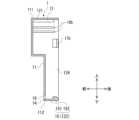
図5は、組付部1を模式的に表した背面図である。図5では、組付部1を簡略化して図示している。図6は、図5のA-A断面図である。図5に示すように、組付部1は、背面視(正面視)矩形状の第1パネル11と、第1パネル11の周縁から後方へ起立した周壁部12と、を含む。第1パネル11の周縁は、上辺111、下辺112、及び一対の側辺113,114を含む。一対の側辺113,114は、上辺111及び下辺112に直交している。周壁部12は、第1上壁121、第1下壁122、及び一対の第1側壁123,124を含む。第1上壁121は上辺111から起立しており、第1下壁122は下辺112から起立している。一対の第1側壁123,124は、夫々、一対の側辺113,114から起立している。第1下壁122は、本発明に係る「第1係合壁」の一例であり、一対の第1側壁123,124は、本発明に係る「第1直交係合壁」の一例である。 [Assembly section 1]
FIG. 5 is a rear view showing the mounting
図5及び図6に示すように、第1上壁121には、第1上壁121の起立方向に沿って延びる上壁リブ13が設けられている。上壁リブ13は、第1上壁121に強度を付与するためのリブであり、後述するように樹脂パネル10と本体部20との位置決めにも用いられる。As shown in Figures 5 and 6, the first
また、図5及び図6に示すように、組付部1には、ベース部14、係合部15、及び位置決め穴16が設けられている。図7は、係合部15付近の斜視図である。図7に示すように、ベース部14は、第1パネル11の一部として形成されている。係合部15は、第1下壁122の一部として形成された、スナップフィット形式の係合手段である。また、係合部15は、延在部151と係合突起152とを含む。延在部151は、ベース部14から立ち上がって後方に延びている。係合突起152は、延在部151に設けられており、延在部151の延在方向と直交する方向に突出している。本例では、係合突起152は、上方に突出している。As shown in Figs. 5 and 6, the mounting
図7の符号CP1は、ベース部14における係合部15との接続部分を示す。図7に示すように、位置決め穴16は、ベース部14の係合部15との接続部CP1の周囲に形成された穴である。つまり、位置決め穴16は、ベース部14における係合部15の根元に形成されている。ここで、図8は、位置決め穴16と係合突起152との位置関係を説明するための図である。図8では、延在部151の延在方向に沿って視認した状態が図示されている。図8の符号P1は、延在部151の延在方向(本例では前後方向)に直交する仮想の平面を示す。また、符号A1は、位置決め穴16を平面P1に射影した領域を示す。また、符号A2は、係合突起152を平面P1に射影した領域を示す。図8に示すように、係合突起152の射影領域A2の全体が位置決め穴16の射影領域A1に含まれている。The symbol CP1 in FIG. 7 indicates the connection portion with the engaging
また、図9は、射出成形により樹脂パネル10を成形する時の金型を模式的に示す断面図である。図9の符号C1は、キャビティを示し、符号C2はコアを示す。本例の樹脂パネル10は、前後2方向抜きの金型により射出成形される。このとき、図9に示すように、係合部15を形成するためには、金型の抜き方向に対して直交する方向に突出した係合突起152を成形する必要がある。つまり、係合部15は、いわゆるアンダーカット形状となっている。そのため、図9に示すように、係合部15は、コアC2の一部をキャビティC1側に突出させた、いわゆる食い切り構造により成形される。キャビティC1側に突出したコアC2の突出部C21により、係合突起152が成形される。このとき、ベース部14には、離型時に突出部C21が抜けるための抜き孔として、位置決め穴16が形成
される。そのため、位置決め穴16は、上述のように、係合突起152の射影領域A2の全体が位置決め穴16の射影領域A1に含まれるように、形成されている。これにより、位置決め穴16は、ベース部14における延在部151の根元のうち、係合突起152に対向する位置に形成されている。また、位置決め穴16は、係合部15を成形するための抜き孔であることから、貫通孔として形成されている。図2に示すように、位置決め穴16は、樹脂パネル10を貫通しており、樹脂パネル10の前面に開口している。位置決め穴16は、本発明に係る「穴」の一例である。 FIG. 9 is a cross-sectional view showing a mold when the
図5及び図6に示すように、第1側壁123には、スナップフィット形式の側壁係合部17aと第1側壁123の起立方向に沿って延びる側壁リブ18aとが併設されている。側壁係合部17aは、第1側壁123の一部として形成されている。また、側壁リブ18aは、第1側壁123に強度を付与するためのリブであり、後述するように樹脂パネル10と本体部20との位置決めにも用いられる。同様に、第1側壁124には、スナップフィット形式の側壁係合部17bと第1側壁124の起立方向に沿って延びる側壁リブ18bとが併設されている。側壁係合部17bは、第1側壁124の一部として形成されている。また、側壁リブ18bは、第1側壁124に強度を付与するためのリブであり、後述するように樹脂パネル10と本体部20との位置決めにも用いられる。側壁リブ18a,18bは、本発明に係る「リブ」の一例である。5 and 6, the
[組付パネル2]
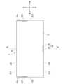
図10は、組付パネル2を模式的に表した正面図である。図10では、組付パネル2を簡略化して図示している。図11は、図10のB-B断面図である。図10に示すように、組付パネル2は、正面視矩形状の第2パネル21を含む。第2パネル21の周縁は、上辺211、下辺212、及び一対の側辺213,214を含む。一対の側辺213,214は、上辺211及び下辺212に直交している。また、組付パネル2は、第2上壁221、第2下壁222、及び一対の第2側壁223,224を含む。第2上壁221は上辺211から起立しており、第2下壁222は下辺212から起立している。一対の第2側壁223,224は、夫々、一対の側辺213,214から起立している。第2下壁222は、本発明に係る「第2係合壁」の一例であり、一対の第2側壁223,224は、本発明に係る「第2直交係合壁」の一例である。 [Assembly panel 2]
FIG. 10 is a front view showing the assembled
図10及び図11に示すように、第2上壁221には、第2上壁221の起立方向に沿って延びる上壁位置決め溝23が設けられている。上壁位置決め溝23は、組付部1の上壁リブ13を受け入れ可能な溝である。As shown in Figures 10 and 11, the second
また、図10及び図11に示すように、組付パネル2の第2下壁222には、挿入部24が設けられている。図12は、挿入部24付近の斜視図である。図12に示すように、挿入部24は、第2下壁222の一部として形成されており、第2パネル21から前方に延びている。また、挿入部24は、係止部25と位置決め突起26とを含む。係止部25は、挿入部24の基端部に設けられた孔の内壁として形成されており、組付部1の係合部15の係合突起152と係合することで、係合部15を係止する。位置決め突起26は、挿入部24の先端部(前端部)として形成された突起であり、組付部1の位置決め穴16に挿入可能となっている。位置決め突起26は、本発明に係る「突起」の一例である。10 and 11, an
図10及び図11に示すように、第2側壁223には、側壁係止部27aと側壁溝28aとが併設されている。側壁係止部27aは、第2側壁223に設けられた孔の内壁として形成されており、組付部1の側壁係合部17aと係合することで、側壁係合部17aを係止する。側壁溝28aは、第2側壁223の起立方向に沿って延びる溝であり、組付部1の側壁リブ18aを受け入れ可能となっている。同様に、第2側壁224には、側壁係止部27bと側壁溝28bとが併設されている。側壁係止部27bは、第2側壁224に
設けられた孔の内壁として形成されており、組付部1の側壁係合部17bと係合することで、側壁係合部17bを係止する。側壁溝28bは、第2側壁224の起立方向に沿って延びる溝であり、組付部1の側壁リブ18bを受け入れ可能となっている。側壁溝28a,28bは、本発明に係る「溝」の一例である。 As shown in Figs. 10 and 11, the
[組付方法]
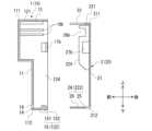
図13は、組立体100における組付部1と組付パネル2の状態を模式的に表した背面図である。図13では、組付部1及び組付パネル2を簡略化して図示している。図14は、図13のC-C断面図である。以下、本体部20に対する樹脂パネル10の組付方法について説明する。 [Assembly method]
Fig. 13 is a rear view showing a schematic state of the
図13及び図14に示すように組付部1と組付パネル2とを連結することで、樹脂パネル10が本体部20に組み付けられる。具体的には、組付部1の位置決め穴16に組付パネル2の位置決め突起26を挿入し、組付部1の上壁リブ13を組付パネル2の上壁位置決め溝23に受け入れ、組付部1の側壁リブ18a,18bを組付パネル2の側壁溝28a,28bに受け入れた状態とする。そして、組付部1の係合部15と組付パネル2の係止部25とを係合させ、組付部1の側壁係合部17a,17bと組付パネル2の側壁係止部27a,27bとを係合させる。組付部1の位置決め穴16に組付パネル2の位置決め突起26が挿入され、組付部1の上壁リブ13が組付パネル2の上壁位置決め溝23に受け入れられることによって、樹脂パネル10の本体部20に対する左右方向の移動が規制される。これにより、樹脂パネル10と本体部20の左右方向における位置決めがなされる。また、組付部1の側壁リブ18a,18bが組付パネル2の側壁溝28a,28bに受け入れられることによって、樹脂パネル10の本体部20に対する上下方向の移動が規制される。これにより、樹脂パネル10と本体部20の上下方向における位置決めがなされる。そして、組付部1の係合部15と組付パネル2の係止部25とが係合し、組付部1の側壁係合部17a,17bと組付パネル2の側壁係止部27a,27bとが係合することで、樹脂パネル10が本体部20に対して固定される。これを仮固定状態とし、ネジ等の締結部材を用いて更に固定してもよい。13 and 14, the
ここで、図15~図17は、樹脂パネル10を本体部20に組み付ける過程を示す断面図である。組付部1と組付パネル2とを連結させるには、まず、図15に示すように、本体部20の前方に樹脂パネル10を配置する。次に、図15に示した状態から、樹脂パネル10を本体部20側(後方)へ移動させる。このとき、組付部1の位置決め穴16に組付パネル2の位置決め突起26が挿入されるように樹脂パネル10を本体部20に対して位置合わせした状態で、樹脂パネル10を移動させる。上述のように、位置決め穴16は、ベース部14における係合突起152と対向する位置に形成されている。そのため、図16に示すように、位置決め穴16に位置決め突起26が挿入される前に、係合突起152が位置決め突起26に当接することとなる。この状態で、係合部15の弾性力に抗して樹脂パネル10を本体部20側へ更に移動させると、図17に示すように、位置決め突起26が係合突起152を乗り越える。この状態で、樹脂パネル10を本体部20側へ更に移動させると、図14に示すように、位置決め突起26が位置決め穴16に挿入される。15 to 17 are cross-sectional views showing the process of assembling the
図15~図17に示すように、位置決め突起26及び係止部25が設けられた挿入部24は、位置決め穴16に対する位置決め突起26の挿入方向(本例では、前方向)に沿って延びている。そして、挿入方向において、係止部25が位置決め突起26よりも手前側に位置している。そのため、挿入部24を挿入方向に沿って移動させると、位置決め突起26が係合突起152を乗り越えて位置決め穴16に挿入されることで、係合突起152が係止部25と係合することとなる。As shown in Figures 15 to 17, the
また、図1に示すように、樹脂パネル10が本体部20に組み付けられた組立体100
の状態では、樹脂パネル10の前面において、位置決め突起26が位置決め穴16から突出している。上述のように、位置決め穴16は、樹脂パネル10を前後に貫通する抜き孔である。そのため、作業者は、樹脂パネル10を本体部20に組み付ける際に、樹脂パネル10の前面側から位置決め穴16を通じて組付パネル2の位置決め突起26を視認し、位置決め穴16と位置決め突起26の位置合わせを行うことができる。 As shown in FIG. 1, an
In this state, the
[作用・効果]
以上のように、本実施形態に係る組付構造は、樹脂パネル10に設けられた組付部1と、本体部20に設けられた組付パネル2と、を備える。また、組付部1は、ベース部14と、ベース部14から立ち上がって延びるスナップフィット形式の係合部15と、ベース部14の係合部15との接続部CP1の周囲に形成された、位置決め穴16と、を含む。また、組付パネル2は、係合部15と係合することで係合部15を係止する係止部25と、位置決め穴16に挿入可能な、位置決め突起26と、を含む。そして、位置決め突起26が位置決め穴16に挿入された状態で、係合部15と係止部25とが係合する。 [Action and Effects]
As described above, the assembly structure according to this embodiment includes an
本実施形態に係る組付構造では、樹脂パネル10と本体部20との位置決めに利用可能な位置決め穴16が樹脂パネル10と本体部20とを固定するための係合部15の根元(接続部CP1の周囲)に形成されている。つまり、位置決め手段と係合手段とが同じ箇所に設けられている。これにより、本実施形態に係る組付構造によれば、位置決め手段と係合手段とを別々の箇所に設ける場合と比較して、これらを設けるために必要なスペースを低減することができる。つまり、省スペース化を実現できる。その結果、製品の小型化に資することができる。In the assembly structure according to this embodiment, a
更に、本実施形態に係る係合部15は、ベース部14から立ち上がって延びる延在部151と、延在部151に設けられ、延在部151の延在方向と直交する方向へ突出した係合突起152であって、係止部25に係合する係合突起152と、を含む。また、位置決め穴16は、係合突起152と位置決め穴16とを延在部151の延在方向と直交する平面P1に射影したときに、係合突起152の射影領域A2の全体が位置決め穴16の射影領域A1に含まれるように、形成されている。また、係止部25及び位置決め突起26は、位置決め穴16に対する位置決め突起26の挿入方向に沿って延びる挿入部24に設けられている。そして、挿入方向において、係止部25が位置決め突起26よりも手前側に位置している。これによると、位置決め突起26を位置決め穴16に挿入するために挿入部24を挿入方向に沿って移動させると、係合突起152が係止部25に係合することとなる。これにより、位置決め突起26を位置決め穴16に挿入するための一の動作で、係合突起152を係止部25に係合させることができる。その結果、組み付けの作業性を向上させることができる。Furthermore, the
更に、本実施形態では、樹脂パネル10は、樹脂製であり、位置決め穴16は、金型により係合部15を成形するためにベース部14に形成された抜き孔である。これによると、成形時の抜き孔を位置決め手段として利用することで、別途位置決め手段を設ける場合と比較して、必要なスペースを小さくすることができる。なお、本例では、樹脂パネル10の全体が樹脂製であるが、本発明は第1の部品の全体が樹脂製でなくともよい。第1の部品に設けられた第1組付部のみが樹脂製であってもよい。また、本発明に係る位置決め穴は、抜き孔でなくともよい。Furthermore, in this embodiment, the
更に、本実施形態に係る組付部1は、正面視矩形状の第1パネル11と、第1パネル11の下辺112から起立した第1下壁122と、下辺112に直交する一対の側辺113,114から起立した一対の第1側壁123,124と、を含む。また、組付パネル2は、正面視矩形状の第2パネル21と、第2パネルの下辺212から起立した第2下壁222と、下辺212に直交する一対の側辺213,214から起立した一対の第2側壁22
3,224と、を含む。また、ベース部14は、第1パネル11の一部として形成されており、係合部15は、第1下壁122の一部として形成されている。また、係止部25及び位置決め突起26は、第2下壁222の一部として形成されている。また、一対の第1側壁123,124には、夫々、一対の第1側壁123,124の起立方向に沿って延びる側壁リブ18a,18bが設けられている。そして、一対の第2側壁223,224には、夫々、側壁リブ18a,18bを受け入れ可能な側壁溝28a,28bが設けられている。そのため、側壁リブ18a,18bと側壁溝28a,28bとを位置決めに利用することができる。これによると、第1パネル11の一辺である下辺112と下辺112に直交する一対の側辺113,114とに位置決め手段を配置することで、樹脂パネル10の本体部20に対する組み付けを精度よく行うことができる。また、係合手段である側壁係合部17a,17bと位置決め手段である側壁リブ18a,18bとを併設することで、省スペース化を実現できる。なお、本例では、第1パネル11の下辺112と一対の側辺113,114とに係合手段及び位置決め手段を配置したが、本発明はこれに限定されない。つまり、パネルにおいて、係合手段及び位置決め手段が配置される辺は特に限定されない。 Furthermore, the mounting
3, 224. The
更に、本実施形態に係る位置決め穴16は、樹脂パネル10を貫通する貫通孔として形成されている。これによると、作業者は、樹脂パネル10を本体部20に組み付ける際に、樹脂パネル10の前面側から、つまり、樹脂パネル10を挟んで本体部20の反対側から、位置決め穴16を通じて組付パネル2の位置決め突起26を視認し、位置決め穴16と位置決め突起26の位置合わせを行うことができる。そのため、作業者は、位置決めが正しくなされたか否かを目で見て確認することができる。これにより、本体部20に対する樹脂パネル10の組み付けが容易となる。その結果、組み付けの作業性を向上させることができる。なお、本発明に係る位置決め穴は、貫通孔でなくともよい。Furthermore, the
<その他>
以上、実施形態を参照して本発明を説明したが、本発明は上記実施の形態に限定されるものではない。 <Other>
Although the present invention has been described above with reference to the embodiment, the present invention is not limited to the above embodiment.
1・・・・・組付部(第1組付部の一例)
15・・・・係合部
16・・・・位置決め穴(穴の一例)
2・・・・・組付パネル(第2組付部の一例)
25・・・・係止部
26・・・・位置決め突起(突起の一例)
10・・・・樹脂パネル(第1の部品の一例)
20・・・・本体部(第2の部品の一例)
100・・・組立体1... Assembly portion (an example of a first assembly portion)
15: Engagement portion 16: Positioning hole (an example of a hole)
2. Assembly panel (an example of a second assembly portion)
25: Locking portion 26: Positioning protrusion (an example of a protrusion)
10... Resin panel (an example of the first component)
20... Main body (an example of the second component)
100...Assembly
Claims (4)
Translated fromJapanese前記第1の部品に設けられた第1組付部と、
前記第2の部品に設けられた第2組付部と、を備え、
前記第1組付部は、ベース部と、前記ベース部から立ち上がって延びるスナップフィット形式の係合部と、前記ベース部の前記係合部との接続部の周囲に形成された穴と、を含み、
前記第2組付部は、前記係合部と係合することで前記係合部を係止する係止部と、前記穴に挿入可能な突起と、を含み、
前記突起が前記穴に挿入された状態で、前記係合部と前記係止部とが係合し、
前記第1組付部は、正面視矩形状の第1パネルと、前記第1パネルの一辺から起立した第1係合壁と、前記第1パネルの前記一辺に直交する二辺から起立した一対の第1直交係合壁と、を含み、
前記第2組付部は、正面視矩形状の第2パネルと、前記第2パネルの一辺から起立した第2係合壁と、前記第2パネルの前記一辺に直交する二辺から起立した一対の第2直交係合壁と、を含み、
前記ベース部は、前記第1パネルの一部として形成されており、
前記係合部は、前記第1係合壁の一部として形成されており、
前記突起及び前記係止部は、前記第2係合壁の一部として形成されており、
前記一対の第1直交係合壁には、夫々、前記第1直交係合壁の起立方向に沿って延びるリブが設けられ、
前記一対の第2直交係合壁には、夫々、前記リブを受け入れ可能な溝が設けられている、
組付構造。 An assembly structure for assembling a first part to a second part, comprising:
a first assembly portion provided on the first component;
A second assembly portion provided on the second component,
the first assembly portion includes a base portion, a snap-fit type engagement portion extending upright from the base portion, and a hole formed around a connection portion of the base portion with the engagement portion,
the second assembly portion includes a locking portion that locks the engaging portion by engaging with the engaging portion, and a protrusion that can be inserted into the hole,
When the projection is inserted into the hole, the engagement portion and the locking portion areengaged with each other,
The first assembly portion includes a first panel having a rectangular shape in a front view, a first engagement wall standing from one side of the first panel, and a pair of first perpendicular engagement walls standing from two sides of the first panel perpendicular to the one side,
The second assembly portion includes a second panel having a rectangular shape in a front view, a second engagement wall standing from one side of the second panel, and a pair of second perpendicular engagement walls standing from two sides of the second panel perpendicular to the one side,
the base portion is formed as a part of the first panel;
The engagement portion is formed as a part of the first engagement wall,
the projection and the locking portion are formed as part of the second engagement wall,
The pair of first perpendicular engagement walls are each provided with a rib extending along a rising direction of the first perpendicular engagement wall,
The pair of second orthogonal engagement walls each have a groove capable of receiving the rib.
Assembly structure.
前記穴は、前記係合突起と前記穴とを前記延在方向と直交する平面に射影したときに、前記係合突起の領域全体が前記穴の領域に含まれるように、形成されている、
請求項1に記載の組付構造。 the engaging portion includes an extending portion that rises and extends from the base portion, and an engaging protrusion that is provided on the extending portion, protrudes in a direction perpendicular to an extending direction of the extending portion, and engages with the locking portion;
The hole is formed such that, when the engagement projection and the hole are projected onto a plane perpendicular to the extension direction, the entire area of the engagement projection is included in the area of the hole.
The assembly structure according to claim 1.
請求項2に記載の組付構造。 The locking portion and the protrusion are provided in an insertion portion extending along an insertion direction of the protrusion into the hole.
The assembly structure according to claim 2.
前記穴は、金型により前記係合部を成形するために前記ベース部に形成された抜き孔である、
請求項1から3の何れか一項に記載の組付構造。 The first assembly portion is made of resin,
The hole is a punched hole formed in the base portion for molding the engagement portion by a mold.
The assembly structure according to any one of claims 1 to 3.
Priority Applications (3)
| Application Number | Priority Date | Filing Date | Title |
|---|---|---|---|
| JP2021050930AJP7577585B2 (en) | 2021-03-25 | 2021-03-25 | Assembly Structure |
| CN202111110680.9ACN115135050B (en) | 2021-03-25 | 2021-09-22 | Assembling the structure |
| US17/520,094US12104630B2 (en) | 2021-03-25 | 2021-11-05 | Assembly structure |
Applications Claiming Priority (1)
| Application Number | Priority Date | Filing Date | Title |
|---|---|---|---|
| JP2021050930AJP7577585B2 (en) | 2021-03-25 | 2021-03-25 | Assembly Structure |
Publications (2)
| Publication Number | Publication Date |
|---|---|
| JP2022149014A JP2022149014A (en) | 2022-10-06 |
| JP7577585B2true JP7577585B2 (en) | 2024-11-05 |
Family
ID=83364408
Family Applications (1)
| Application Number | Title | Priority Date | Filing Date |
|---|---|---|---|
| JP2021050930AActiveJP7577585B2 (en) | 2021-03-25 | 2021-03-25 | Assembly Structure |
Country Status (3)
| Country | Link |
|---|---|
| US (1) | US12104630B2 (en) |
| JP (1) | JP7577585B2 (en) |
| CN (1) | CN115135050B (en) |
Families Citing this family (1)
| Publication number | Priority date | Publication date | Assignee | Title |
|---|---|---|---|---|
| TWI858997B (en)* | 2023-11-15 | 2024-10-11 | 華碩電腦股份有限公司 | Baffle structure |
Citations (2)
| Publication number | Priority date | Publication date | Assignee | Title |
|---|---|---|---|---|
| JP2011010373A (en) | 2009-06-23 | 2011-01-13 | Yazaki Corp | Partitioned electrical junction box |
| JP2019158588A (en) | 2018-03-13 | 2019-09-19 | オムロン株式会社 | Limited reflection type sensor |
Family Cites Families (19)
| Publication number | Priority date | Publication date | Assignee | Title |
|---|---|---|---|---|
| JPS6020175U (en)* | 1983-07-20 | 1985-02-12 | 日置電機株式会社 | case for electronic equipment |
| JP2582779Y2 (en)* | 1993-10-12 | 1998-10-08 | 住友電装株式会社 | Lock structure of electrical junction box |
| JP3200546B2 (en)* | 1995-09-04 | 2001-08-20 | 矢崎総業株式会社 | Movable connector |
| US5743606A (en)* | 1996-08-16 | 1998-04-28 | Dell U.S.A., L.P. | Computer cabinet latching mechanism |
| TW353263B (en)* | 1996-11-21 | 1999-02-21 | Koninkl Philips Electronics Nv | Detachable connection between two housing sections |
| US7733659B2 (en) | 2006-08-18 | 2010-06-08 | Delphi Technologies, Inc. | Lightweight audio system for automotive applications and method |
| US20110017742A1 (en)* | 2009-07-23 | 2011-01-27 | Delphi Technologies, Inc. | In-Groove Snap Fastener |
| JP5281534B2 (en)* | 2009-10-05 | 2013-09-04 | ホシデン株式会社 | Terminal box |
| CN103547098A (en)* | 2012-07-16 | 2014-01-29 | 深圳富泰宏精密工业有限公司 | Electronic device casing locking structure and disassembly method thereof |
| JP6191093B2 (en)* | 2014-07-23 | 2017-09-06 | 住友電装株式会社 | Electrical junction box |
| JP6388121B2 (en)* | 2014-09-30 | 2018-09-12 | アイシン精機株式会社 | Vehicle door handle device |
| US9653901B2 (en)* | 2014-10-22 | 2017-05-16 | Daiwa Kasei Industry Co., Ltd. | Holding component for vehicle |
| CN107852832B (en)* | 2015-08-04 | 2020-03-06 | 三菱电机株式会社 | Assembly structure of casing of electronic equipment and electronic equipment |
| DE102017204600A1 (en)* | 2017-03-20 | 2018-09-20 | Robert Bosch Gmbh | A connector for connecting two housing parts and housings comprising two housing parts and at least one connector |
| KR102003661B1 (en)* | 2017-04-14 | 2019-07-24 | 미쓰비시덴키 가부시키가이샤 | Industrial equipment |
| FR3071485B1 (en)* | 2017-09-28 | 2019-10-25 | Sagemcom Broadband Sas | CASING COMPRISING A FIRST PORTION OF HOUSING, A SECOND PORTION OF HOUSING AND A THIRD PORTION OF HOUSING |
| CN208075392U (en)* | 2018-03-30 | 2018-11-09 | 日本电产三协(浙江)有限公司 | Ice maker |
| JP7083701B2 (en)* | 2018-06-07 | 2022-06-13 | 矢崎総業株式会社 | Lock structure, electrical junction box and wire harness |
| JP7158900B2 (en)* | 2018-06-07 | 2022-10-24 | 矢崎総業株式会社 | Lock structure, electrical connection box and wire harness |
- 2021
- 2021-03-25JPJP2021050930Apatent/JP7577585B2/enactiveActive
- 2021-09-22CNCN202111110680.9Apatent/CN115135050B/enactiveActive
- 2021-11-05USUS17/520,094patent/US12104630B2/enactiveActive
Patent Citations (2)
| Publication number | Priority date | Publication date | Assignee | Title |
|---|---|---|---|---|
| JP2011010373A (en) | 2009-06-23 | 2011-01-13 | Yazaki Corp | Partitioned electrical junction box |
| JP2019158588A (en) | 2018-03-13 | 2019-09-19 | オムロン株式会社 | Limited reflection type sensor |
Also Published As
| Publication number | Publication date |
|---|---|
| US20220307528A1 (en) | 2022-09-29 |
| CN115135050B (en) | 2025-03-28 |
| US12104630B2 (en) | 2024-10-01 |
| JP2022149014A (en) | 2022-10-06 |
| CN115135050A (en) | 2022-09-30 |
Similar Documents
| Publication | Publication Date | Title |
|---|---|---|
| US6628524B1 (en) | Frame kit for IC card and IC card using the same | |
| KR101289526B1 (en) | Electronic unit case and method of manufacturing electronic unit | |
| JP7577585B2 (en) | Assembly Structure | |
| CN111284414B (en) | Detection device | |
| CN204488662U (en) | Electronic machine pre-fix structure | |
| CN111284416B (en) | Detection device | |
| US7746281B2 (en) | Antenna mounting assembly | |
| JP2002314264A (en) | Casing for storing electronic component | |
| JP4872731B2 (en) | Mounting structure of switch device | |
| JP2014038944A (en) | Electronic equipment | |
| JP4972717B2 (en) | Equipment housing | |
| JP3112152B2 (en) | Cover mounting structure | |
| JP7626010B2 (en) | In-vehicle equipment | |
| JP4107088B2 (en) | Rearview mirror for vehicles | |
| JP2000311750A (en) | Connector fixing structure for wire harness | |
| JP5004137B2 (en) | Two-component mounting structure | |
| JP5129045B2 (en) | Connector housing with latch | |
| JP2003243106A (en) | Mounting adapter for connector | |
| JP2000013477A (en) | Attachment structure for transparent cover | |
| JP2022086096A (en) | Panel assembly structure | |
| JPH10321291A (en) | Connector mounting structure | |
| JP2001351744A (en) | Movable structure of connector | |
| KR100745452B1 (en) | Crash Pad Pinning Structure | |
| CN117641792A (en) | Electronic equipment with cover | |
| JP2025142945A (en) | Resin housing |
Legal Events
| Date | Code | Title | Description |
|---|---|---|---|
| A621 | Written request for application examination | Free format text:JAPANESE INTERMEDIATE CODE: A621 Effective date:20240131 | |
| A977 | Report on retrieval | Free format text:JAPANESE INTERMEDIATE CODE: A971007 Effective date:20240725 | |
| A131 | Notification of reasons for refusal | Free format text:JAPANESE INTERMEDIATE CODE: A131 Effective date:20240730 | |
| A521 | Request for written amendment filed | Free format text:JAPANESE INTERMEDIATE CODE: A523 Effective date:20240911 | |
| TRDD | Decision of grant or rejection written | ||
| A01 | Written decision to grant a patent or to grant a registration (utility model) | Free format text:JAPANESE INTERMEDIATE CODE: A01 Effective date:20241001 | |
| A61 | First payment of annual fees (during grant procedure) | Free format text:JAPANESE INTERMEDIATE CODE: A61 Effective date:20241023 | |
| R150 | Certificate of patent or registration of utility model | Ref document number:7577585 Country of ref document:JP Free format text:JAPANESE INTERMEDIATE CODE: R150 |