JP7576564B2 - Method and apparatus for in-line dimensional control of multiple manufactured objects - Patents.com - Google Patents
Method and apparatus for in-line dimensional control of multiple manufactured objects - Patents.comDownload PDFInfo
- Publication number
- JP7576564B2 JP7576564B2JP2021563427AJP2021563427AJP7576564B2JP 7576564 B2JP7576564 B2JP 7576564B2JP 2021563427 AJP2021563427 AJP 2021563427AJP 2021563427 AJP2021563427 AJP 2021563427AJP 7576564 B2JP7576564 B2JP 7576564B2
- Authority
- JP
- Japan
- Prior art keywords
- cross
- dimensional
- projection
- area
- objects
- Prior art date
- Legal status (The legal status is an assumption and is not a legal conclusion. Google has not performed a legal analysis and makes no representation as to the accuracy of the status listed.)
- Active
Links
Images


Classifications
- G—PHYSICS
- G06—COMPUTING OR CALCULATING; COUNTING
- G06T—IMAGE DATA PROCESSING OR GENERATION, IN GENERAL
- G06T7/00—Image analysis
- G06T7/0002—Inspection of images, e.g. flaw detection
- G06T7/0004—Industrial image inspection
- G06T7/001—Industrial image inspection using an image reference approach
- G—PHYSICS
- G06—COMPUTING OR CALCULATING; COUNTING
- G06T—IMAGE DATA PROCESSING OR GENERATION, IN GENERAL
- G06T7/00—Image analysis
- G06T7/0002—Inspection of images, e.g. flaw detection
- G06T7/0004—Industrial image inspection
- G—PHYSICS
- G01—MEASURING; TESTING
- G01B—MEASURING LENGTH, THICKNESS OR SIMILAR LINEAR DIMENSIONS; MEASURING ANGLES; MEASURING AREAS; MEASURING IRREGULARITIES OF SURFACES OR CONTOURS
- G01B15/00—Measuring arrangements characterised by the use of electromagnetic waves or particle radiation, e.g. by the use of microwaves, X-rays, gamma rays or electrons
- G—PHYSICS
- G06—COMPUTING OR CALCULATING; COUNTING
- G06T—IMAGE DATA PROCESSING OR GENERATION, IN GENERAL
- G06T17/00—Three dimensional [3D] modelling, e.g. data description of 3D objects
- G—PHYSICS
- G06—COMPUTING OR CALCULATING; COUNTING
- G06T—IMAGE DATA PROCESSING OR GENERATION, IN GENERAL
- G06T7/00—Image analysis
- G06T7/60—Analysis of geometric attributes
- G06T7/62—Analysis of geometric attributes of area, perimeter, diameter or volume
- G—PHYSICS
- G06—COMPUTING OR CALCULATING; COUNTING
- G06T—IMAGE DATA PROCESSING OR GENERATION, IN GENERAL
- G06T7/00—Image analysis
- G06T7/60—Analysis of geometric attributes
- G06T7/64—Analysis of geometric attributes of convexity or concavity
- H—ELECTRICITY
- H04—ELECTRIC COMMUNICATION TECHNIQUE
- H04N—PICTORIAL COMMUNICATION, e.g. TELEVISION
- H04N23/00—Cameras or camera modules comprising electronic image sensors; Control thereof
- H04N23/56—Cameras or camera modules comprising electronic image sensors; Control thereof provided with illuminating means
- H—ELECTRICITY
- H04—ELECTRIC COMMUNICATION TECHNIQUE
- H04N—PICTORIAL COMMUNICATION, e.g. TELEVISION
- H04N23/00—Cameras or camera modules comprising electronic image sensors; Control thereof
- H04N23/90—Arrangement of cameras or camera modules, e.g. multiple cameras in TV studios or sports stadiums
- G—PHYSICS
- G06—COMPUTING OR CALCULATING; COUNTING
- G06T—IMAGE DATA PROCESSING OR GENERATION, IN GENERAL
- G06T2200/00—Indexing scheme for image data processing or generation, in general
- G06T2200/08—Indexing scheme for image data processing or generation, in general involving all processing steps from image acquisition to 3D model generation
- G—PHYSICS
- G06—COMPUTING OR CALCULATING; COUNTING
- G06T—IMAGE DATA PROCESSING OR GENERATION, IN GENERAL
- G06T2207/00—Indexing scheme for image analysis or image enhancement
- G06T2207/10—Image acquisition modality
- G06T2207/10028—Range image; Depth image; 3D point clouds
- G—PHYSICS
- G06—COMPUTING OR CALCULATING; COUNTING
- G06T—IMAGE DATA PROCESSING OR GENERATION, IN GENERAL
- G06T2207/00—Indexing scheme for image analysis or image enhancement
- G06T2207/10—Image acquisition modality
- G06T2207/10072—Tomographic images
- G06T2207/10081—Computed x-ray tomography [CT]
- G—PHYSICS
- G06—COMPUTING OR CALCULATING; COUNTING
- G06T—IMAGE DATA PROCESSING OR GENERATION, IN GENERAL
- G06T2207/00—Indexing scheme for image analysis or image enhancement
- G06T2207/10—Image acquisition modality
- G06T2207/10116—X-ray image
- G—PHYSICS
- G06—COMPUTING OR CALCULATING; COUNTING
- G06T—IMAGE DATA PROCESSING OR GENERATION, IN GENERAL
- G06T2207/00—Indexing scheme for image analysis or image enhancement
- G06T2207/20—Special algorithmic details
- G06T2207/20112—Image segmentation details
- G—PHYSICS
- G06—COMPUTING OR CALCULATING; COUNTING
- G06T—IMAGE DATA PROCESSING OR GENERATION, IN GENERAL
- G06T2207/00—Indexing scheme for image analysis or image enhancement
- G06T2207/30—Subject of image; Context of image processing
- G06T2207/30108—Industrial image inspection
- G—PHYSICS
- G06—COMPUTING OR CALCULATING; COUNTING
- G06T—IMAGE DATA PROCESSING OR GENERATION, IN GENERAL
- G06T2207/00—Indexing scheme for image analysis or image enhancement
- G06T2207/30—Subject of image; Context of image processing
- G06T2207/30241—Trajectory
- G—PHYSICS
- G06—COMPUTING OR CALCULATING; COUNTING
- G06T—IMAGE DATA PROCESSING OR GENERATION, IN GENERAL
- G06T2210/00—Indexing scheme for image generation or computer graphics
- G06T2210/56—Particle system, point based geometry or rendering
Landscapes
- Engineering & Computer Science (AREA)
- Physics & Mathematics (AREA)
- General Physics & Mathematics (AREA)
- Theoretical Computer Science (AREA)
- Computer Vision & Pattern Recognition (AREA)
- Geometry (AREA)
- Signal Processing (AREA)
- Multimedia (AREA)
- Quality & Reliability (AREA)
- Software Systems (AREA)
- Computer Graphics (AREA)
- Electromagnetism (AREA)
- Analysing Materials By The Use Of Radiation (AREA)
- Length-Measuring Devices Using Wave Or Particle Radiation (AREA)
- Image Analysis (AREA)
Description
Translated fromJapanese本発明は、複数の物体のシリーズを構成する複数の製造物体の寸法のX線検査の分野に関する。The present invention relates to the field of X-ray inspection of the dimensions of multiple manufactured objects constituting a series of multiple objects.
本発明は、より具体的には、複数の直線寸法の、つまり、例えば、容器、成型又は機械加工部品、機械部品、梱包用容器、車体要素などの一般的な意味での製造物体が有する複数の長さの、X線測定値を得ることを目的とする。The invention more specifically aims to obtain X-ray measurements of multiple linear dimensions, i.e. multiple lengths, of manufactured objects in the general sense, such as, for example, containers, molded or machined parts, machine parts, packaging containers, vehicle body elements, etc.
従来技術により、X線による複数の物体の寸法検査を可能にする様々な技術が知られている。手荷物検査システムも知られているが、これは、既知の複数の物体の寸法の測定ではなく、ほぼランダムな配置、形状及び量の禁制物又は禁制材料の検出を意図している。The prior art knows various techniques that allow for dimensional inspection of multiple objects by X-ray. Baggage inspection systems are also known, but these are intended to detect prohibited objects or materials of substantially random configuration, shape and quantity, rather than to measure the dimensions of multiple known objects.
例として、コンピュータ断層撮影又はCT(コンピュータ・トモグラフィー)を含む軸回転システムが知られている。この従来の方法は、J.P.Kruthらによる「寸法計測のためのコンピュータ・トモグラフィー」という記事に記載されている。As an example, a rotating axis system including computed tomography or CT (Computed Tomography) is known. This conventional method is described in the article "Computed Tomography for Dimensional Metrology" by J.P. Kruth et al.
それは、Volume 60, Issue 2, 2011, Pages 821-842に記載されており、また、例えばベアト(Werth Messtechnik)社又はゼネラル・エレクトリック社が販売している断層撮影装置に実装されている。この方法は、X線発生管とマトリクス又はリニアX線イメージセンサとの間で、垂直軸周りのターンテーブル上に物体を配置することを含む。回転中に、非常に多数(少なくとも100、多くの場合600以上)の2D放射線画像が取得される。イメージセンサがマトリクスイメージセンサの場合、そのビームは円錐状である。イメージセンサがリニアである場合、そのビームは、その回転軸に直交する平面における扇(扇状ビーム)内に有利に制限され、ヘリカル型のフルスキャンの場合、回転は、回転の垂直軸に沿った並進を伴う。この技術により、高精度の三次元測定が提供されうる。ただし、最速のシステムでも、少なくとも1分の取得時間を要し、これに複数の物体の上げ下ろし時間が追加されるので、1時間あたりに検査されるのは最大10から30の物体である。It is described in Volume 60,
回転ガントリーと呼ばれる別の解決策が、例えば、ゼネラル・エレクトリック社から「スピードスキャンCT64」という商品名で知られる装置によって提供されている。一部の3D手荷物用のスキャナと同様に、この解決策の概念は、線源、物体及びイメージセンサの間の相対的な動きという点で、医療用画像断層撮影装置に似ている。実際、コンベヤ上に配置された複数の製造物体又は手荷物は、上記機器内を並進する。それらは、その移動方向に直交する投射平面を通り抜ける。上記平面を含む円形のガントリーにおいて、X線源及びこの線源の反対側にある一般的に湾曲したイメージセンサは、移動の中心軸周りを回転し、これにより、1スライスずつ又はヘリカルスキャンによって、3D再構築のために必要な複数の投射が、例えば「フィルタ補正逆投影」法又はART法を実行するアルゴリズムによって、得られる。これらの機器の目的は、ガントリーの各回転で非常に多数の投射、例えばスライス毎に100、さらには700から1000の画像の取得を可能とすることである。複数の物体の3D再構築は、例えば1スライスずつ行われる。実際には、スライスの任意の点で減衰量を特定して、物体の移動中に得られた複数のスライスを連結することにより、物体の任意の体積要素の減衰量の値が得られる。Another solution, called a rotating gantry, is offered, for example, by a device known under the trade name "SpeedScan CT64" from General Electric. As with some 3D baggage scanners, the concept of this solution is similar to a medical tomography device in terms of the relative movement between the radiation source, the object and the image sensor. In fact, multiple manufactured objects or baggage placed on a conveyor translate through the device. They pass through a projection plane perpendicular to their direction of movement. In a circular gantry containing the plane, the X-ray source and a generally curved image sensor opposite the source rotate around the central axis of movement, so that the multiple projections required for the 3D reconstruction are obtained slice by slice or by helical scanning, for example by algorithms implementing the "filtered back projection" or ART method. The aim of these devices is to allow the acquisition of a very large number of projections with each rotation of the gantry, for example 100 or even 700 to 1000 images per slice. The 3D reconstruction of multiple objects is performed, for example, slice by slice. In practice, the attenuation value for any volume element of the object can be obtained by determining the attenuation at any point in the slice and concatenating multiple slices taken while the object is moving.
提供される多数の画像のおかげで、これらの垂直軸回転又は回転ガントリー機器が非常に正確である場合、これらの機器は高価で低速であるので、現実面ではオフライン検査のために取っておかれている。1m/sの走行で毎分600物品に達しそれを超えることができる速度でのインライン寸法検査には適していないからである。While these vertical axis rotating or rotating gantry instruments are very accurate thanks to the large number of images they provide, in practice they are reserved for offline inspection as they are expensive and slow, making them unsuitable for in-line dimensional inspection at speeds that can reach and exceed 600 articles per minute at 1 m/s travel.
特許出願DE 10 2014 103137には、断層像密度検出器のシステムを使用して、加工部品の幾何学的特性を特定する方法が記載されており、当該方法は、X線源と、平面検出器と、上記部品を回転させるための又は上記X線源及び上記検出器を回転させるための機械軸とを含む。Patent application DE 10 2014 103137 describes a method for determining geometrical properties of a workpiece using a tomographic density detector system, which comprises an X-ray source, a planar detector and a mechanical axis for rotating the part or for rotating the X-ray source and the detector.
上記方法によれば、回転中に複数の放射線画像が取得され、その表面のモデルを使用して表面の図形が確保される。このような方法は、計算時間を短縮するために、体積データ再構築ステップの実行を回避する。このような技術では、製造された複数の部品を高速で測定することは不可能である。1つの部品をターンテーブルに上げてから、少なくとも180°回転させ、その後、別の部品の検査のために下ろす必要があるからである。According to the above method, multiple radiographic images are acquired during the rotation and a model of the surface is used to obtain the surface geometry. Such a method avoids performing a volumetric data reconstruction step in order to reduce computation time. Such a technique does not allow for rapid measurement of multiple manufactured parts, since one part needs to be raised on the turntable, rotated at least 180°, and then lowered for inspection of another part.
回転ガントリーに搭載された上記管とイメージセンサの欠点を克服するために、特許US 8 971 484には、回転システムが複数の固定マルチビームX線源の配列に置き換えられた手荷物検査システムが記載されており、上記配列は、異なる投射角度で多数の放射線画像を提供するための複数のX線源の仮想変位を引き起こすために連続的に作動する。1秒あたり4回転に制限されている物理的回転システムと比較すると、「仮想回転」の数は1秒あたり40回転に増加している。ラピスキャン・システムズ社のラピスキャンRTTの商品名で知られる機器によって実行されるこの技術によれば、仮想回転が約40の異なる投射角度を提供することを考慮すると、複数の手荷物の何万もの2D画像を作成することによって、1時間あたり1200の手荷物を検査することができる。To overcome the drawbacks of the tubes and image sensors mounted on a rotating gantry, patent US 8 971 484 describes a baggage inspection system in which the rotation system is replaced by an array of multiple fixed multi-beam X-ray sources, which are operated in succession to cause virtual displacements of the multiple X-ray sources to provide a multitude of radiographic images at different projection angles. In comparison with a physical rotation system limited to four rotations per second, the number of "virtual rotations" is increased to 40 rotations per second. According to this technique, implemented by an instrument known under the trade name Rapiscan RTT from Rapiscan Systems, 1200 pieces of baggage can be inspected per hour by creating tens of thousands of 2D images of multiple pieces of baggage, considering that the virtual rotation provides about 40 different projection angles.
この技術は、X線マルチ源の価格の高さと、非常に大量のデータを処理するのに必要とされる計算能力のせいで、非常に高価であることが判明している。加えて、その検査速度は依然として制限されており、インライン検査には適していない。This technique has proven to be very expensive due to the high cost of the X-ray multi-source and the computing power required to process the very large amounts of data. In addition, its inspection speed is still limited and it is not suitable for in-line inspection.
特許US 7 319 737及びUS 7 221 732は、デジタル断層撮影又はトモシンセシスと呼ばれる技術によって複数の手荷物を検査することを提案している。複数の手荷物は、扇状ビームと呼ばれる一連の円錐形投射平面を通り抜け、各投射平面には、L字型に配置された1対のリニアイメージセンサが含まれる。これらの技術は、様々な形状の物体及び材料を含む手荷物内の武器又は爆発物を、手荷物内のそれらの3D位置を視覚化することによって、かつ、例えば疑わしい製品の体積を評価することによって、捜索することを意図している。上記材料の原子番号をも特定するために、マルチスペクトル技術を使用するのは一般的なことである。したがって、これらのシステムでは、手荷物の任意の点で減衰量値を特定しようとする。一方、これらのシステムにより、品質検査の目的のために複数の製造物体の寸法を高速かつ正確に特定することは不可能である。Patents US 7 319 737 and US 7 221 732 propose to inspect baggage pieces by a technique called digital tomography or tomosynthesis. The baggage pieces pass through a series of cone-shaped projection planes called fan beams, each of which contains a pair of linear image sensors arranged in an L-shape. These techniques are intended to search for weapons or explosives in baggage, which contains objects and materials of various shapes, by visualizing their 3D position in the baggage and by evaluating, for example, the volume of suspicious products. It is common to use multispectral techniques to also determine the atomic number of said materials. These systems therefore seek to determine the attenuation value at any point of the baggage. On the other hand, it is not possible with these systems to rapidly and accurately determine the dimensions of manufactured objects for the purpose of quality inspection.
特許出願JP S60 260807は、それぞれが複数のセンサと関連付けられている1つ又は複数の焦点に由来するX線による測定を使用して、自身の軸に沿って並進で動かされる管の壁の厚さを測定することを提案している。複数の焦点及び複数のセンサは、管の移動方向に直交する平面に沿って複数の放射線投射を生成するように配置されている。したがって、複数の放射線投射は、管の対称軸に直交する投射平面と同一平面上にある。これらの放射線投射の方向は、上記移動方向に対して直角(90°)をなす。この技術により、管の内表面及び外表面を完全に知ることは不可能である。この特許出願に記載される方法では、投射方向における管の2つの壁の累積厚さのみが測定可能であり、他の複数の方向において正確な測定が行われることを可能とする管の三次元モデルの再構築はなされない。Patent application JP S60 260807 proposes measuring the thickness of the wall of a tube moved in translation along its axis using measurements by X-rays originating from one or more focal points, each associated with a number of sensors. The focal points and the sensors are arranged to generate a number of radiation projections along a plane perpendicular to the direction of movement of the tube. The radiation projections are therefore coplanar with a projection plane perpendicular to the axis of symmetry of the tube. The direction of these radiation projections is perpendicular (90°) to said direction of movement. With this technique it is not possible to obtain complete knowledge of the inner and outer surfaces of the tube. The method described in this patent application allows only the cumulative thickness of the two walls of the tube in the projection direction to be measured, without reconstructing a three-dimensional model of the tube that allows accurate measurements to be made in other directions.
同じように、特許US 5 864 600には、容器輸送コンベヤのいずれかの側に横方向に配置されたX線源とセンサとを使用して、容器の充填レベルを特定する方法が記載されている。この文献は複数の容器の三次元モデリングを提供していないため、このシステムでは、横方向に配向されていない表面に対して測定を行うことが不可能である。Similarly, patent US 5 864 600 describes a method for determining the filling level of containers using X-ray sources and sensors arranged laterally on either side of a container transport conveyor. This document does not provide three-dimensional modeling of multiple containers, so the system is not capable of performing measurements on surfaces that are not laterally oriented.
特許出願US 2009/0262891には、コンベヤによって並進移動させられた複数の手荷物内に置かれた複数の物体を、X線によって検出するためのシステムが記載されている。このシステムは、複数のパルス発生管又は走行方向に平行な寸法の大きいセンサを含む。この文献は、物体を再構築する方法を提供しているが、移動方向における投射の欠如により、移動方向に直交する方向における寸法の測定が不可能であるため、満足のいくものではない。ある角度セクタにおける放射線投射の欠如により、正確な測定を確保するのに適したデジタルモデルを作成することが不可能となっている。Patent application US 2009/0262891 describes a system for detecting by X-ray several objects placed in several pieces of baggage translated by a conveyor. The system comprises several pulse generating tubes or sensors with a large dimension parallel to the direction of travel. This document provides a method for reconstructing the object, but it is unsatisfactory since the lack of projection in the direction of travel makes it impossible to measure the dimensions in a direction perpendicular to the direction of travel. The lack of radiation projection in an angular sector makes it impossible to create a digital model suitable for ensuring accurate measurements.
特許出願DE 197 56 697には、特許出願US 2009/0262891と同じ欠点を有する装置が記載されている。Patent application DE 197 56 697 describes a device that has the same drawbacks as patent application US 2009/0262891.
特許出願WO 2010/092368には、放射線源及び3つのリニアセンサを使用して、並進移動している物体をX線によって視覚化するための装置が記載されている。Patent application WO 2010/092368 describes an apparatus for X-ray visualization of a translationally moving object using a radiation source and three linear sensors.
特許出願US 2010/220910には、理想物体を表す3D基準モデルを作成することによって、物体の異常を検出するための方法が記載されている。この方法は、実際の物体の取得された2D画像を上記基準モデルに対応する2D画像と比較して、そこから異常を推測することを意図している。この方法では、物体の正確な測定を行うことは不可能であり、作成された複数の2D画像においてのみ、よって複数の投射方向と直交する複数の方向のみにおいて、物体を検査することが可能である。Patent application US 2010/220910 describes a method for detecting anomalies in an object by creating a 3D reference model representing an ideal object. The method aims to compare acquired 2D images of the real object with 2D images corresponding to said reference model and to infer anomalies therefrom. With this method it is not possible to perform an exact measurement of the object, but it is possible to inspect it only in the created 2D images and thus in the directions orthogonal to the projection directions.
文献WO2018014138には、製造品の検査を行うための方法が記載されている。この方法は、ある品物の一連の放射線画像を取得すること、取得した各放射線画像についてその品物の外郭構造の三次元位置を特定すること、及びメッシュネットワークの形状で詳細な三次元モデル補正ループを行うことを含み、それは、その品物の特定された位置ごとにシミュレートされた放射線画像の生成、並びにシミュレートされた放射線画像と取得された放射線画像との比較及び一致結果の生成を反復的に含む。上記ペアリングの結果が不一致を示している場合、上記方法は、シミュレートされた放射線画像と取得された放射線画像との差異の識別及び材料密度又は三次元構造に関するそれらの原因の特定、識別されかつ特徴付けられた差異のそれぞれに基づく品物の詳細な三次元モデルの対象領域の構造及び材料密度のうちの1つの修正、並びに新たな反復の実行を含む。したがって、この文献は、三次元モデル補正ループ、つまり、3D幾何学的形状の実行に基づいて機能するので、かなりの計算を要する。加えて、この文献は、この三次元モデル補正ループを可能にするために、画像の連続的なシーケンスを定義する少なくとも約25の放射線画像、好ましくは約100の放射線画像を実行する必要があることを教示しており、各画像は品物に固有の視野角を提供する。Document WO2018014138 describes a method for inspecting manufactured items. The method includes acquiring a series of radiographic images of an item, determining for each acquired radiographic image the three-dimensional location of the outer structure of the item, and performing a detailed three-dimensional model correction loop in the form of a mesh network, which includes iteratively generating a simulated radiographic image for each determined location of the item, and comparing the simulated and acquired radiographic images and generating a match result. If the result of the pairing indicates a mismatch, the method includes identifying differences between the simulated and acquired radiographic images and identifying their causes in terms of material density or three-dimensional structure, modifying one of the structure and material density of the target area of the detailed three-dimensional model of the item based on each identified and characterized difference, and performing a new iteration. This document therefore requires significant calculations, since it works on the basis of performing a three-dimensional model correction loop, i.e., a 3D geometric shape. In addition, this document teaches that to enable this three-dimensional model correction loop, it is necessary to perform at least about 25 radiographic images, preferably about 100 radiographic images, that define a continuous sequence of images, each image providing a unique viewing angle of the item.
J.P.Kruthらによる出版物である「寸法計測のためのコンピュータ・トモグラフィー」CIRP ANNALS, vol. 60, no. 2, December 31, 2011, pages 821-842, ISSN: 0007-8506, DOI: 10.1016/J.CIRP.2011.05.0は、次元計測学に適用されるX線トモグラフィーの技術の概要を提供する。この文献には、特に、この技術の基本原理が、複数の投射画像の数学的再構築が3Dボクセルモデルの元となることを意味していること、そして、部品(セグメンテーション)の複数のエッジの検出のための、かつ、寸法測定のための、ボクセルデータの後処理を含むことが示されている。この文献にはまた、この技術の基本原理が、自身の軸を中心とする物体の回転を含むことが示されている。The publication "Computed Tomography for Dimensional Metrology" by J.P.Kruth et al., CIRP ANNALS, vol. 60, no. 2, December 31, 2011, pages 821-842, ISSN: 0007-8506, DOI: 10.1016/J.CIRP.2011.05.0, provides an overview of the technique of X-ray tomography applied to dimensional metrology. It shows, in particular, that the basic principle of the technique involves the mathematical reconstruction of multiple projection images, which means the origin of a 3D voxel model, and the post-processing of the voxel data for the detection of edges of the part (segmentation) and for dimensional measurement. It also shows that the basic principle of the technique involves the rotation of an object around its own axis.
文献US2009/262891には、幾何学的再構築ではなく標準的な画像化を行うシステムが記載されているが、かなりの角度サンプリングが必要であるので、物体の軌道方向に非常に多数のユニットセンサ要素が必要となる。したがって、物体の軌道方向に配向された複数の線に沿った高密度の複数の「フォトサイト」を含む複数の平面検出器が必要となる。換言すると、フィルタ処理された背面投射アルゴリズムを使用する3D再構築システムは、物体の軌道方向に多くのユニットセンサ要素を必要とするので、ユニットセンサ要素の総数に関する要求が非常に厳しい。Document US2009/262891 describes a system that performs standard imaging rather than geometric reconstruction, but requires a significant angular sampling, which requires a very large number of unit sensor elements in the object's trajectory direction. Planar detectors are therefore required that contain a high density of "photosites" along lines oriented in the object's trajectory direction. In other words, 3D reconstruction systems using filtered backprojection algorithms require many unit sensor elements in the object's trajectory direction, which makes very strict demands on the total number of unit sensor elements.
本発明は、実行される安価な方法を提供することによって、及び高速で並進走行する複数の製造物体の正確な寸法のX線検査を可能にすることによって、従来技術の欠点を克服することを目的とする。特に、この方法は、妥当な価格の機器を用いて高い検査レートに到達するために、減らした計算量でそのような検査を可能とすることを目的とする。The present invention aims to overcome the drawbacks of the prior art by providing an inexpensive method to be implemented and by enabling dimensionally accurate X-ray inspection of multiple manufactured objects in translation at high speed. In particular, the method aims to enable such inspection with reduced computational effort in order to reach high inspection rates using reasonably priced equipment.
断層撮影において、所定方向の周囲の放射線投射の欠如は、この方向に平行な複数の表面の再構築を妨げ、寸法検査のために、欠落している放射線投射に直交する寸法の測定ができなくなる「欠落境界」現象を発生させることが知られている。In tomography, it is known that the absence of surrounding radiation projections in a given direction prevents the reconstruction of multiple surfaces parallel to this direction, resulting in the "missing boundary" phenomenon, which, for dimensional inspection, makes it impossible to measure dimensions perpendicular to the missing radiation projections.
したがって、本発明はまた、並進で移動する複数の物体について、放射線投射の数には制限があって複数の物体の搬送方向の周辺では得られないものの、正確で完全な三次元デジタルモデルを構築することによって、正確な測定を行うことを可能とする方法を提供することを目的とする。The present invention therefore also aims to provide a method that allows accurate measurements to be made of multiple objects moving in translation, even though the number of radiation projections is limited and cannot be obtained around the transport direction of the multiple objects, by constructing an accurate and complete three-dimensional digital model.
本発明は、1シリーズの複数の製造物体の複数の直線寸法を自動的に測定する方法に関し、当該方法は、
複数の製造物体のシリーズを選択することと、ここで、複数の物体のそれぞれは、1つ又は複数の異なる部分からなり、部分の数は既知であって、かつ、各部分は、物体の部分の任意の点において均一な既知の減衰係数を有する材料で作られており、
輸送装置を用いて、搬送平面における直線軌道に沿った移動方向に複数の物体を輸送することと、ここで、これらの物体は、移動中に搬送体積を生成し、
搬送体積の外側に、X線発生管の少なくとも1つの焦点を配置することと、ここで、各焦点は、直線軌道に沿った移動方向に平行な同一の基準直線上に配列され、
搬送体積の外側に、関連付けられた焦点に由来する複数のX線に曝されかつ感度を持つ1つ又は複数のイメージセンサを配置することと、ここで、これらのX線は、少なくとも検査対象領域を通り抜けて、投射方向に沿った検査対象領域の放射線投射を各イメージセンサ上に生成し、
1つ又は複数のイメージセンサ(Ci,Cik)を使用して、移動中の各物体について、複数の一次元処理用放射線画像のセットを取得することと、ここで、各一次元処理用放射線画像は、基準直線を含む断面平面(Pk)に沿った物体の断面の投射を含み、
ここで、上記セットは、
基準直線を含むいくつか(NK)の異なる断面平面(Pk)についての一次元処理用放射線画像と、
異なる各断面平面(Pk)についての、検査対象領域のいくつか(NP)の一次元処理用放射線画像(Spk)と、ここで、一次元処理用放射線画像(Spk)は、上記断面平面における少なくとも3つの異なる投射方向(Dijk)に沿って得られ、
を含み、
各測定対象物体について、かつ、異なる各断面平面(Pk)について、コンピュータシステムを使用して、検査対象領域の複数の一次元処理用放射線画像(Spk)から、検討された断面平面(Pk)における物体の描写を特定することと、ここで、上記描写は、上記断面平面における少なくとも3つの異なる投射方向(Dijk)に沿って得られ、
測定対象物体について、異なる各断面平面における物体の複数の描写から、測定対象物体の検査対象領域の直線寸法の少なくとも1つの測定値を特定することと、
を備える。 The present invention relates to a method for automatically measuring a plurality of linear dimensions of a series of a plurality of manufactured objects, the method comprising:
selecting a series of a plurality of manufactured objects, where each of the plurality of objects is comprised of one or more distinct portions, the number of portions being known, and each portion being made of a material having a known damping coefficient that is uniform at any point in the portion of the object;
Transporting a plurality of objects in a direction of travel along a linear trajectory in a transport plane using a transport device, where the objects generate a transport volume during the travel;
disposing at least one focal point of the X-ray generating tube outside the transport volume, wherein each focal point is arranged on the same reference straight line parallel to the direction of movement along the straight trajectory;
disposing one or more image sensors outside the transport volume that are exposed to and sensitive to a plurality of X-rays originating from an associated focal point, where these X-rays pass through at least the examination target area to generate on each image sensor a radiation projection of the examination target area along a projection direction;
acquiring, for each moving object, a set of a plurality of one-dimensional processing radiographic images using one or more image sensors (Ci, Cik), where each one-dimensional processing radiographic image comprises a projection of a cross-section of the object along a cross-sectional plane (Pk) that includes a reference line;
Here, the set is
one-dimensional processing radiographic images for several (NK) different cross-sectional planes (Pk) including a reference line;
one-dimensional processing radiation images (Spk) of some of the examination areas (NP) for each different cross-sectional plane (Pk), where the one-dimensional processing radiation images (Spk) are obtained along at least three different projection directions (Dijk) in said cross-sectional plane,
Including,
for each measurement object and for each different cross-sectional plane (Pk), determining, using a computer system, from a plurality of one-dimensional processing radiation images (Spk) of the area under examination, a representation of the object in the considered cross-sectional plane (Pk), said representation being obtained along at least three different projection directions (Dijk) in said cross-sectional plane,
determining, for the measured object, at least one measurement of a linear dimension of an area under examination of the measured object from a plurality of representations of the object at each of the different cross-sectional planes;
Equipped with.
任意であるが互いに組み合わせることが可能な本発明に係る方法の他の特徴が、以下の段落に記載される。Other features of the method according to the invention, which may be optionally combined with each other, are described in the following paragraphs.
物体の描写は、物体の複数の境界表面の断面平面との交差部分を表す曲線又は複数の曲線のセットを含みうるか、又は上記曲線又は上記曲線のセットによって構成されうる。The representation of the object may include or be composed of a curve or set of curves that represent the intersections of the object's boundary surfaces with the cross-sectional plane.
物体の描写の上記曲線又は各曲線は、パラメトリックシステムによってモデル化された平面曲線でありうる。The or each curve of the representation of the object may be a planar curve modeled by a parametric system.
断面平面における物体の描写の特定は、断面平面における物体の推測的描写からのカーブフィッティングアルゴリズムを含みうる。Identifying the representation of the object in the cross-sectional plane may involve a curve fitting algorithm from an a priori representation of the object in the cross-sectional plane.
断面平面における物体の描写の特定は、非線形回帰型のカーブフィッティングアルゴリズムを含みうる。Determining the representation of the object in the cross-sectional plane may involve a non-linear regression type curve fitting algorithm.
断面平面における物体の描写の特定は、反復的カーブフィッティングアルゴリズムを含み、上記反復的カーブフィッティングアルゴリズムは、
第1反復ランクの計算された描写として、断面平面における物体の推測的描写を検討することと、
その後、反復的に、
断面平面における物体の所定の反復ランクの計算された描写から、検査対象領域の少なくとも3に等しい数のシミュレートされた一次元放射線画像を計算することと、ここで、上記計算は、断面平面における複数の一次元処理用放射線画像の取得に使用された少なくとも3つの異なる投射方向に沿った断面平面においてなされ、
複数のシミュレートされた一次元放射線画像を上記複数の一次元処理用放射線画像と比較することと、
上記複数のシミュレートされた一次元放射線画像の上記複数の一次元処理用放射線画像との比較が予め定義された最適化基準に達するまで、上記比較に応じて、計算された描写をより高い反復ランクの計算された描写へ修正することと、
を含む。 Identifying a representation of the object in the cross-sectional plane includes an iterative curve fitting algorithm, the iterative curve fitting algorithm comprising:
considering a putative representation of the object in the cross-sectional plane as a calculated representation of the first iterative rank;
Then, iteratively,
calculating a number of simulated one-dimensional radiographic images of the examination area from the calculated representations of the predetermined repetitive ranks of the object in the cross-sectional planes, the number being at least equal to three, wherein said calculations are performed in the cross-sectional planes along at least three different projection directions used to acquire the plurality of one-dimensional processing radiographic images in the cross-sectional planes;
comparing a plurality of simulated one-dimensional radiographic images with the plurality of one-dimensional processing radiographic images;
modifying the calculated representation to a higher iterative rank calculated representation in response to a comparison of the plurality of simulated one-dimensional radiographic images with the plurality of one-dimensional processing radiographic images until a predefined optimization criterion is reached;
Includes.
上記方法は、
複数のイメージセンサを使用して、移動中の各物体について、検査対象領域の少なくとも3に等しい数の二次元放射線画像を取得することと、ここで、二次元放射線画像のそれぞれは異なる投射方向に沿って得られ、
上記複数の二次元放射線画像において、複数の一次元処理用放射線画像を抽出して、複数の一次元放射線画像のセットを形成することと、
を含みうる。 The above method is
acquiring, for each moving object, a number of two-dimensional radiographic images of the area under examination equal to at least three, using a plurality of image sensors, where each of the two-dimensional radiographic images is obtained along a different projection direction;
extracting a plurality of one-dimensional processing radiographic images from the plurality of two-dimensional radiographic images to form a set of a plurality of one-dimensional radiographic images;
may include.
物体の一次元処理用放射線画像は、物体の移動中、焦点とポイントイメージセンサとの間の物体の移動の継続時間に対応するスキャン継続時間中に、ポイントイメージセンサを使用して取得された点像のサンプリングによって形成されうる。A one-dimensional processing radiographic image of the object may be formed by sampling point images acquired using the point image sensor during the movement of the object, during a scan duration corresponding to the duration of the object's movement between the focal point and the point image sensor.
上記方法は、測定対象物体について、コンピュータシステムを使用して、かつ、異なる複数の断面平面のそれぞれにおける物体の複数の描写から、検査対象領域の三次元デジタル幾何モデルを構築することを含むことができ、上記三次元デジタル幾何モデルは、
それぞれが物体の検査対象領域の境界表面に属する空間内の複数の三次元点、
及び/又は検査対象領域の少なくとも1つの三次元表面、
を備える。 The method may include constructing, for the object to be measured, a three-dimensional digital geometric model of the area to be examined using a computer system and from a plurality of representations of the object at each of a plurality of different cross-sectional planes, the three-dimensional digital geometric model comprising:
a plurality of three-dimensional points in space, each of which belongs to a boundary surface of a region of interest of the object;
and/or at least one three-dimensional surface of the area to be examined;
Equipped with.
測定対象物体について、異なる各断面平面における物体の複数の描写から、測定対象物体の検査対象領域の少なくとも1つの直線寸法の測定を特定することは、検査対象領域の三次元デジタル幾何モデルの少なくとも2つの三次元点の間の距離を特定することを含みうる。For a measured object, determining a measurement of at least one linear dimension of an inspected area of the measured object from multiple representations of the object in different cross-sectional planes may include determining a distance between at least two three-dimensional points of a three-dimensional digital geometric model of the inspected area.
上記方法は、各断面平面について、断面平面における物体の推測的描写をコンピュータシステムへ提供することを含みうる。The method may include, for each cross-sectional plane, providing to the computer system a speculative representation of the object at the cross-sectional plane.
複数の推測的描写は、
上記シリーズの複数の物体のコンピュータ支援設計デジタルモデルによって、
及び/又は測定装置による同じシリーズの1つ又は複数の物体の測定から、
及び/又はコンピュータシステムのマンマシンインターフェース上のオペレータによって入力された値及び/又は作成された図面及び/又は選択された形状から、
得られうる。 Several speculative portrayals include:
Computer-aided design digital models of several objects in the above series
and/or from measurements of one or more objects of the same series by a measuring device;
and/or from values entered by an operator on a man-machine interface of the computer system and/or from drawings created and/or shapes selected,
It can be obtained.
上記方法は、上記シリーズの検査対象領域の推測的三次元幾何モデルをコンピュータシステムへ提供することを含みえ、上記推測的三次元幾何モデルは、
上記シリーズの複数の物体のコンピュータ支援設計デジタルモデル、
及び/又は測定装置による同じシリーズの1つ又は複数の物体の測定から得られたデジタル幾何モデル、
及び/又はコンピュータシステムのマンマシンインターフェース上のオペレータによって入力された値及び/又は作成された図面及び/又は選択された形状からコンピュータシステムによって生成されたデジタル幾何モデル、
によって得られうる。 The method may include providing an a priori three-dimensional geometric model of an area of interest of the series to a computer system, the a priori three-dimensional geometric model comprising:
Computer-aided design digital models of a number of objects in the above series;
and/or a digital geometric model obtained from measurements of one or more objects of the same series by a measuring device;
and/or a digital geometric model generated by the computer system from values entered and/or drawings created and/or shapes selected by an operator on a man-machine interface of the computer system;
It can be obtained by
上記方法は、搬送平面に1つ又は複数の焦点を配置することを含みうる。The method may include positioning one or more focal points at the conveying plane.
上記方法は、1つ又は複数のイメージセンサを使用して、移動中の上記シリーズの物体について、かつ、物体の検討された各断面平面について、検討された断面平面において45°以上90°以下、有利には60°以上90°以下の有効角度を定義する複数の投射方向に対応する検査領域の少なくとも2つの一次元処理用放射線画像を取得することを含みうる。The method may comprise acquiring, using one or more image sensors, for the object of the series in motion and for each considered cross-sectional plane of the object, at least two one-dimensional processing radiographic images of the examination area corresponding to a number of projection directions defining an effective angle in the considered cross-sectional plane between 45° and 90°, preferably between 60° and 90°.
上記方法は、1つ又は複数のイメージセンサを使用して、移動中の上記シリーズの物体について、かつ、物体の検討された各断面平面について、移動方向に対して0°から60°をなす開き角度を有し、搬送平面に投射をもたらす投射方向に対応する検査領域の少なくとも1つの放射線画像を取得することを含みうる。The method may include acquiring, using one or more image sensors, for the object of the series in motion and for each considered cross-sectional plane of the object, at least one radiographic image of an examination area having an opening angle between 0° and 60° with respect to the direction of motion and corresponding to a projection direction resulting in a projection on the conveying plane.
上記方法は、1つ又は複数のイメージセンサを使用して、移動中の上記シリーズの各物体について、移動方向に対して10°未満をなす開き角度を有する投射方向に対応する検査領域の放射線画像を取得することを含まなくともよい。The method may not include acquiring, using one or more image sensors, for each object of the series during movement, a radiographic image of an examination area corresponding to a projection direction having an opening angle of less than 10° with respect to the direction of movement.
上記方法は、1つ又は複数の焦点に由来し、かつ、複数のイメージセンサに到達する複数のX線が別の物体を通り抜けないように、物体の検査領域の放射線投射を実行すること及び取得することを含みうる。The method may include performing and acquiring a radiation projection of an examination region of an object such that multiple X-rays originating from one or multiple focal points and reaching multiple image sensors do not pass through another object.
上記方法は、移動中の上記シリーズの各物体について、かつ、各断面について、異なる複数の投射方向の検査対象領域の3から40の範囲の放射線投射に由来する、好ましくは、異なる複数の投射方向の検査対象領域の4から15の範囲の放射線投射に由来する、複数の一次元処理用放射線画像を取得することを含みうる。The method may include obtaining, for each object of the series during movement and for each cross section, a number of one-dimensional processing radiation images resulting from radiation projections in the range of 3 to 40 of the examined area in a number of different projection directions, preferably from radiation projections in the range of 4 to 15 of the examined area in a number of different projection directions.
いくつかの実施形態では、複数のイメージセンサは、少なくとも3つの物理センサ要素の一部を構成していてもよく、少なくとも3つ物理センサ要素のそれぞれはリニアタイプであり、それぞれが支持直線に沿って分布した複数のX線感応素子の直線配列を含み、焦点とともに投射方向を含む投射平面を定義し、これらのイメージセンサは、
これらの物理センサ要素のそれぞれの少なくともm個の感応素子が、焦点に由来するX線ビームによって検査対象領域の放射線投射を受け取り、
異なる複数の物理センサ要素についての複数の投射平面が互いに異なり、かつ、搬送平面に平行ではなく、
少なくとも3つのリニア物理センサ要素のそれぞれを使用して、軌道に沿った各物体の増分変位毎に、検査対象領域の複数の一次元放射線画像が、各物体について、検査対象領域の全体が、複数の一次元放射線画像のセットに完全に表されるように選択された数に従って取得され、
検査対象領域の複数の一次元放射線画像の少なくとも3セットが各物体について分析される、
ように配置されている。 In some embodiments, the plurality of image sensors may form part of at least three physical sensor elements, each of which is of linear type and each of which comprises a linear array of a plurality of X-ray sensitive elements distributed along a support line and defines a projection plane that includes the projection direction together with the focal point, and these image sensors:
at least m sensitive elements of each of these physical sensor elements receive a radiation projection of the examination area by the X-ray beam originating from the focal point;
the projection planes for the different physical sensor elements are different from each other and are not parallel to the transport plane;
a plurality of one-dimensional radiographic images of the examination target area are acquired for each object for each incremental displacement along the trajectory using at least three respective linear physical sensor elements, according to a number selected such that the entire examination target area is completely represented in the set of the plurality of one-dimensional radiographic images;
At least three sets of a plurality of one-dimensional radiological images of the examination area are analyzed for each object;
They are arranged as follows.
本発明はさらに、1シリーズの複数の製造物体の少なくとも1つの検査対象領域の複数の直線寸法を自動的に測定するための設備に関し、上記設備は、
搬送平面における直線軌道に沿って、変位ベクトルによって具体化された方向に複数の物体を輸送するための装置と、ここで、複数の物体は、移動方向に延びる搬送体積を通って走行し、
通過された体積の外側に配置されたX線発生管の少なくとも1つの焦点であって、物体の少なくとも1つの検査対象領域を通り抜けるように向けられた発散X線ビームを生成する焦点と、ここで、各焦点は、直線軌道に沿った移動方向に平行な同一の基準直線上に配列され、
関連付けられた焦点に由来する複数のX線を受け取るように搬送体積の外側に配置された複数のイメージセンサと、ここで、1つ又は複数の焦点及び複数のイメージセンサは、焦点に由来する複数のX線によって、物体がこれらのX線を通り抜けるとき、各イメージセンサが検査対象領域の放射線投射を受け取るように配置されており、これらの放射線投射の投射方向は互いに異なっており、
移動中の各物体について、複数の一次元処理用放射線画像のセットを取得するように、複数のイメージセンサに接続された取得システムと、
ここで、上記セットは、
基準直線を含むいくつかの異なる断面平面についての複数の一次処理用放射線画像と、
異なる各断面平面についての、検査対象領域のいくつかの一次元処理用放射線画像と、ここで、これらの一次元処理用放射線画像は、断面平面における少なくとも3つの異なる投射方向に沿って得られ、
を含み、
異なる各断面平面について、少なくとも3つの一次元処理用放射線画像から、検討された断面平面における物体の描写を特定するように構成された、コンピュータシステムと、
を備える。 The invention further relates to an installation for automatically measuring a plurality of linear dimensions of at least one inspection area of a series of a plurality of manufactured objects, said installation comprising:
A device for transporting a plurality of objects along a linear trajectory in a conveying plane in a direction embodied by a displacement vector, in which the plurality of objects travel through a conveying volume extending in the direction of movement,
at least one focal point of an X-ray generating tube disposed outside the traversed volume, the focal point generating a divergent X-ray beam directed through at least one region of the object to be examined, wherein each focal point is arranged on the same reference line parallel to the direction of movement along the linear trajectory;
a plurality of image sensors arranged outside the transport volume to receive a plurality of X-rays from an associated focal point, where the one or more focal points and the plurality of image sensors are arranged such that each image sensor receives a radiation projection of the inspection area by the plurality of X-rays from the focal points as the object passes through the X-rays, the projection directions of the radiation projections being different from each other;
an acquisition system connected to the plurality of image sensors to acquire a set of a plurality of one-dimensional processing radiographic images for each moving object;
Here, the set is
A plurality of primary processing radiographic images for a number of different cross-sectional planes including the reference line;
several one-dimensional processing radiation images of the area under examination for each different cross-sectional plane, where these one-dimensional processing radiation images are obtained along at least three different projection directions in the cross-sectional plane;
Including,
a computer system configured to identify, for each different cross-sectional plane, from the at least three one-dimensional processing radiographic images, a representation of the object in the considered cross-sectional plane;
Equipped with.
任意であるが互いに組み合わせることが可能な本発明に係る設備の他の特徴が、以下の段落に記載される。Other features of the device according to the invention, which may be optionally combined with each other, are described in the following paragraphs.
上記設置は、直線軌道に沿った移動方向に平行な同一の基準直線上の2つの異なる位置に別々に配置された、少なくとも2つのX線発生焦点、及び少なくとも3つのイメージセンサを含むことができ、これらのイメージセンサは、複数のX線に感度を持ち、かつ、
各焦点が、少なくとも前記検査対象領域を通り抜けて少なくとも1つの関連付けられたセンサに到達するように、そのビームを放出し、
各センサが、焦点に関連付けられ、かつ、その焦点に由来して検査対象領域を通り抜けた後の複数のX線を受け取る、
ように配置されている。 The installation may include at least two X-ray generating focal points and at least three image sensors, which are separately arranged at two different positions on the same reference line parallel to the direction of movement along the linear track, the image sensors being sensitive to a plurality of X-rays, and
Emitting the beam such that each focal point passes through at least the examination area and onto at least one associated sensor;
Each sensor is associated with a focal spot and receives a plurality of X-rays originating from that focal spot after passing through the examination area;
They are arranged as follows.
上記設置は、90°以上の開きを持つ発散X線ビームが得られる少なくとも1つの焦点、又は開きの合計が90°以上であり、複数の発散X線ビームが得られる少なくとも2つの焦点を含みうる。The setup may include at least one focal point that provides a diverging X-ray beam with an opening of 90° or more, or at least two focal points that provide multiple diverging X-ray beams with a combined opening of 90° or more.
上記設置は、搬送平面に配置された少なくとも1つの焦点を含みうる。The installation may include at least one focus positioned in the conveying plane.
少なくとも1つの焦点及び2つのイメージセンサは、それらが受け取る検査領域の複数の投射方向が、それらの間に45°以上90°以下、有利には60°以上90°以下の有効角度を有するように配置されうる。The at least one focal point and the two image sensors may be arranged such that the projection directions of the inspection area they receive have an effective angle between them of more than 45° and less than 90°, preferably more than 60° and less than 90°.
少なくとも1つの焦点及び1つのイメージセンサは、物体が複数のセンサの視野を通り抜けるとき、イメージセンサ上の検査領域の投射方向が、移動方向)に対して10°から60°をなす開き角度を有するように配置されうる。At least one focus and one image sensor may be arranged such that when an object passes through the field of view of the multiple sensors, the projection direction of the inspection area on the image sensor has an opening angle of 10° to 60° with respect to the direction of movement.
X線発生管の焦点が通過された体積に配置されておらず、かつ、イメージセンサが搬送体積に配置されていないので、イメージセンサ上の検査領域の投射方向が、移動方向で10°未満の開き角度をなすことはない。Since the focal point of the X-ray generating tube is not located in the passed volume and the image sensor is not located in the transport volume, the projection direction of the inspection area on the image sensor does not form an opening angle of less than 10° in the direction of movement.
複数のイメージセンサ及び複数の焦点は、1つ又は複数の焦点に由来し、かつ、複数のイメージセンサに到達して物体の領域を通り抜ける複数のX線が、一度に別の物体を通り抜けないように配置されている。The multiple image sensors and multiple focal points are arranged such that multiple x-rays originating from one or more focal points and reaching the multiple image sensors and passing through a region of the object do not pass through different objects at the same time.
上記設置は、1つ又は複数のX線発生管に由来する、1つから4つの焦点を含みうる。The setup may include one to four focal points derived from one or more X-ray generating tubes.
複数のイメージセンサの及び関連付けられた複数の焦点の数及び配置は、移動中の上記シリーズの各物体について、複数のイメージセンサ上の検査対象領域の複数の放射線投射が、3から40の範囲の異なる投射方向、好ましくは4から15の範囲の異なる投射方向を有するようになっている。The number and arrangement of the multiple image sensors and associated multiple focal points are such that for each object in the series during movement, the multiple radiation projections of the area under examination on the multiple image sensors have between 3 and 40 different projection directions, preferably between 4 and 15 different projection directions.
複数のイメージセンサは、リニアタイプの複数の物理センサ要素の一部を構成しうる。各要素は、支持直線に沿って分布した複数のX線感応素子の直線配列を含み、関連付けられた焦点で投射方向を含む投射平面を定義し、これらのイメージセンサは、
これらの物理センサ要素のそれぞれの少なくともm個の感応素子が、関連付けられた焦点に由来するX線ビームによって検査対象領域の放射線投射を受け取り、
異なる複数のセンサについての複数の投射平面が互いに異なり、かつ、搬送平面に平行ではない、
ように配置されている。 The image sensors may form part of a number of physical sensor elements of linear type, each element comprising a linear array of X-ray sensitive elements distributed along a support line and defining a projection plane containing a projection direction at an associated focal point, the image sensors being:
at least m sensitive elements of each of these physical sensor elements receive a radiation projection of the examination area by an X-ray beam originating from an associated focal point;
The projection planes for the different sensors are different from each other and are not parallel to the conveying plane.
They are arranged as follows.
いくつかの実施形態では、少なくとも3つのリニアイメージセンサの支持直線は、互いに平行である。In some embodiments, the support lines of at least three linear image sensors are parallel to one another.
いくつかの実施形態では、少なくとも3つのリニア物理センサ要素の支持直線は、搬送平面に直交している。In some embodiments, the support lines of at least three linear physical sensor elements are perpendicular to the transport plane.
先立って、本発明の範囲内で使用される用語のいくつかの定義を以下に示す。First, some definitions of terms used within the scope of this invention are provided below.
X線発生管の焦点Fjは、点X線源、好ましくは、例えば0.01mmから1mmの範囲の直径を有する「マイクロ焦点」であって、発散X線ビームを生成する。任意のタイプの点又は点とみなすことができるX線源を使用することが可能である。The focal point Fj of the X-ray generating tube is a point X-ray source, preferably a "microfocus" with a diameter in the range of, for example, 0.01 mm to 1 mm, generating a diverging X-ray beam. Any type of point or point-like X-ray source can be used.
イメージセンサの感応素子は、X線感応素子、換言すると、例えば0.2×0.2mm又は0.02×0.02mmの寸法の基本表面であって、受け取ったX線を電気信号に変換する。一般に、X線用のイメージセンサの感応素子は、X線を可視光線に変換するシンチレータと、その後可視光線を電気信号に変換する光電センサとを含む。X線を電気信号に直接変換する技術もある。画素は、サンプリングされた画像における点の基本値を指定し、例えば0と最大値との間のそのグレーレベルによって特徴付けられる。例えば、12ビットのデジタル画像について、画素は0から4095の範囲のデジタル値を取る。The sensitive elements of the image sensor are X-ray sensitive elements, in other words elementary surfaces with dimensions of, for example, 0.2x0.2 mm or 0.02x0.02 mm, which convert the received X-rays into an electrical signal. Typically, the sensitive elements of an image sensor for X-rays include a scintillator that converts the X-rays into visible light and a photoelectric sensor that then converts the visible light into an electrical signal. There are also techniques for directly converting X-rays into an electrical signal. A pixel specifies the basic value of a point in the sampled image and is characterized by its gray level, for example between 0 and a maximum value. For example, for a 12-bit digital image, a pixel takes on a digital value ranging from 0 to 4095.
複数の放射線画像を読取る又は取得するためのシステムは、1つ又は複数のX線感応表面を、つまり、以下の説明においては、通常はコンピュータによって実行され、かつ、コンピュータシステムSIによって定められた分析システムに送信されるべき電気信号にX線を変換する1つ又は複数の感応素子を含む複数の表面を含む。同一の感応表面区域に属する複数の感応素子のセットに由来する複数の信号は、取得装置によって取得され、かつ、コンピュータシステムに一緒に送信され、放射線画像を形成する。コンピュータシステムによって分析されるために、複数の放射線画像は、感応表面に可能な限り近いか、例えば感応区域を含む物理センサ要素に統合された電子回路において、あるいは、離れて、例えばコンピュータシステムSIに可能な限り近くで、又はコンピュータシステムSIによって、複数のデジタル放射線画像に好ましくは変換される。A system for reading or acquiring multiple radiographic images comprises one or more X-ray sensitive surfaces, i.e. multiple surfaces comprising one or more sensitive elements that convert X-rays into electrical signals to be transmitted to an analysis system, typically executed by a computer in the following description and defined by a computer system SI. Multiple signals originating from a set of multiple sensitive elements belonging to the same sensitive surface area are acquired by an acquisition device and transmitted together to the computer system to form a radiographic image. To be analyzed by the computer system, the multiple radiographic images are preferably converted into multiple digital radiographic images either as close as possible to the sensitive surface or, for example, in an electronic circuit integrated in a physical sensor element comprising the sensitive area, or remotely, for example, as close as possible to the computer system SI or by the computer system SI.
コンピュータシステムSIは、その例が図3に象徴的に示されているが、少なくとも1つの標準的コンピュータの形式で構成されうる。したがって、コンピュータシステムSIは、少なくとも1つのマイクロプロセッサ、1つ又は複数の電子記憶ユニット及び1つ又は複数のディスプレイ(スクリーン、プロジェクタ、ホログラフィックディスプレイなど)、入力装置(キーボード、マウス、タッチパッド、タッチスクリーンなど)、及び/又は通信(USB、Ethernet(登録商標)、Wi-Fi(登録商標)、Bluetooth(登録商標)、Zigbee(登録商標)など)インターフェースを含む。コンピュータシステムは、ネットワークの1つ又は複数の他のコンピュータと、又は他のネットワークと、例えばインターネット又はEthernet(登録商標)プロトコルによって、データを共有するコンピュータネットワークを含みうる。複数のイメージセンサへの疑う余地のない接続に加えて、コンピュータシステムは、設備の状態に関する情報を提供する複数のセンサに、及び/又は設備の複数のアクチュエーター(コンベヤ、エジェクタなど)に接続されうる。コンピュータシステムは、そこから運転データを取得するために、及び/又はその検査を確実に行うために、有利には1つ又は複数のX線管に接続されうる。コンピュータシステムは、1つ又は複数のリモートコンピュータサーバー上への実装を含む、局所的又は遠隔的に保存及び/又は実行された1つ又は複数のソフトウェアを実装する。この又はこれらのソフトウェアは、好ましくは、本発明に係る方法を実行するようにプログラムされた1つ又は複数のソフトウェアを含む。The computer system SI may be configured in the form of at least one standard computer, an example of which is symbolically shown in FIG. 3. The computer system SI thus includes at least one microprocessor, one or more electronic storage units and one or more displays (screens, projectors, holographic displays, etc.), input devices (keyboards, mice, touchpads, touchscreens, etc.), and/or communication (USB, Ethernet, Wi-Fi, Bluetooth, Zigbee, etc.) interfaces. The computer system may include a computer network that shares data with one or more other computers of the network or with other networks, for example by Internet or Ethernet protocols. In addition to the obvious connection to the multiple image sensors, the computer system may be connected to multiple sensors that provide information about the state of the equipment and/or to multiple actuators of the equipment (conveyors, ejectors, etc.). The computer system may advantageously be connected to one or more X-ray tubes for obtaining operational data therefrom and/or for performing the inspection. The computer system may implement one or more pieces of software stored and/or executed locally or remotely, including on one or more remote computer servers. This or these pieces of software preferably include one or more pieces of software programmed to perform the method according to the present invention.
焦点Fjに由来する複数のX線ビームは、少なくとも1つの検査領域を通り抜けて、感応表面上に検査領域の放射線投射を生成する。放射線投射は、放射画像と呼ばれることもあり、通過された材料による複数のX線の減衰量の情報を含む。The multiple X-ray beams originating from the focal point Fj pass through at least one examination area and generate a radiation projection of the examination area on the sensitive surface. The radiation projection, sometimes called a radiation image, contains information about the attenuation of the multiple X-rays by the material through which they are passed.
検査領域の放射線投射を受け取るX線感応表面区域は、イメージセンサCi、Cikと呼ばれる。イメージセンサCi、Cikは、関連付けられた焦点Fjに由来する複数のX線に曝される。イメージセンサは、この放射線投射を、検査領域の放射線画像に変換する。The X-ray sensitive surface areas that receive the radiation projection of the examination area are called image sensors Ci, Cik. The image sensors Ci, Cik are exposed to a number of X-rays originating from the associated focal point Fj. The image sensors convert this radiation projection into a radiation image of the examination area.
イメージセンサCiに対応する感応表面区域が、支持直線の線分に沿って分布された複数の光感応素子の単列を含むとき、センサの積分時間(取得時間とも呼ばれる)で取得された放射線画像は線形、つまり一次元であり、一次元値テーブルを形成する複数の画素の列から構成される。この場合、イメージセンサCikはリニアセンサと呼ばれる。複数の感応素子の単列を含む感応表面区域は、リニアイメージセンサを構成し、それゆえ支持直線の線分に沿って分布された複数の感応素子の直線配列を含む。この定義によれば、感応マトリクス表面に属する一直線に並べられた複数の感応素子(対角線又は別の傾斜線に沿ったものを含む)の段又は列又は任意のセットは、リニアイメージセンサとみなされる。同一表面の複数の感応表面区域は、それぞれが複数の感応素子の単列を含み、異なる複数の区域の複数の列は異なっており、したがって、複数のリニアイメージセンサを構成する。When the sensitive surface area corresponding to the image sensor Ci comprises a single row of light sensitive elements distributed along a line segment of the support line, the radiation image acquired in the integration time (also called acquisition time) of the sensor is linear, i.e. one-dimensional, and is composed of a row of pixels forming a one-dimensional value table. In this case, the image sensor Cik is called a linear sensor. A sensitive surface area comprising a single row of sensitive elements constitutes a linear image sensor and therefore comprises a linear array of sensitive elements distributed along a line segment of the support line. According to this definition, a row or column or any set of linearly aligned sensitive elements (including along a diagonal or another inclined line) belonging to a sensitive matrix surface is considered as a linear image sensor. Sensitive surface areas of the same surface each comprise a single row of sensitive elements, the columns of different areas being different and therefore constituting linear image sensors.
イメージセンサCiに対応する感応表面区域が複数の光感応素子の二次元マトリクスを含むとき、センサの積分時間で取得された放射線画像は、マトリクスであり、つまり、二次元値テーブルを形成する複数の画素のマトリクスから構成される二次元画像である。この場合、イメージセンサCiは二次元センサ又はマトリクスセンサと呼ばれる。When the sensitive surface area corresponding to the image sensor Ci comprises a two-dimensional matrix of a number of light-sensitive elements, the radiation image acquired during the integration time of the sensor is a matrix, i.e. a two-dimensional image composed of a matrix of a number of pixels forming a two-dimensional value table. In this case, the image sensor Ci is called a two-dimensional sensor or matrix sensor.
イメージセンサCikに対応する感応表面区域が単一の光感応素子を含むとき、センサの積分時間で取得された放射線画像は、点像と呼ばれ、単一の値を有する画素から構成される。よって、イメージセンサCikはポイントセンサと呼ばれる。When the sensitive surface area corresponding to an image sensor Cik contains a single light-sensitive element, the radiation image acquired in the integration time of the sensor is called a point image and consists of pixels having a single value. Thus, the image sensor Cik is called a point sensor.
本発明の範囲内で、イメージセンサCi、Cikは、物理センサ要素CC1、CC2、・・・、CCnmaxに、物理センサ要素CC1、CC2、・・・、CCnmaxの一部に、又は複数の物理センサ要素のアセンブリ又は複数の物理センサ要素の一部に対応しうる。物理センサ要素は、1つ又は複数の感応素子を含み、多数ある場合には互いに固定され、かつ、そのすべての感応素子について、コンピュータシステムと共通の接続インターフェースを含む要素である。共通の接続インターフェースは、アナログ又はデジタルでありうる。共通の接続インターフェースは、一般に、物理センサ要素の統合された電子回路の一部を構成する。複数の感応素子Cikを含む物理センサ要素CC1、CC2、・・・、CCnmaxにおいて、複数の感応素子は、変更可能ではなく、一般に平面であるが湾曲しているものもある線に沿って又は固定表面に沿って配列される。物理センサ要素CC1、CC2、・・・、CCnmaxは、複数の光感応素子の列を含むとき、リニアセンサ要素と呼ばれる。物理センサ要素は、光感応素子の二次元マトリクスを含むとき、二次元又はマトリクスセンサ要素と呼ばれる。物理センサ要素は、単一の光感応素子を含むとき、ポイントセンサ要素と呼ばれる。Within the scope of the present invention, the image sensors Ci, Cik may correspond to a physical sensor element CC1, CC2, ..., CCnmax, to a part of a physical sensor element CC1, CC2, ..., CCnmax, or to an assembly of several physical sensor elements or to a part of several physical sensor elements. A physical sensor element is an element that includes one or several sensitive elements, fixed to one another if there are many, and includes a common connection interface with the computer system for all its sensitive elements. The common connection interface may be analog or digital. The common connection interface generally forms part of the integrated electronic circuit of the physical sensor element. In a physical sensor element CC1, CC2, ..., CCnmax that includes several sensitive elements Cik, the multiple sensitive elements are arranged along a line that is not variable and is generally planar, but may also be curved, or along a fixed surface. A physical sensor element CC1, CC2, ..., CCnmax is called a linear sensor element when it includes a row of several light sensitive elements. When a physical sensor element contains a two-dimensional matrix of light-sensitive elements, it is called a two-dimensional or matrix sensor element. When a physical sensor element contains a single light-sensitive element, it is called a point sensor element.
したがって、本発明の範囲内で、イメージセンサCi、Cikは、複数のX線を電気信号に変換する1つ又は複数の感応素子Cikのセットであり、感応素子は物理要素であることが理解される。複数の物理感応要素のこのセットは、物理センサ要素CC1、CC2、・・・、CCnmaxに対応してもよく、対応しなくてもよい。Therefore, within the scope of the present invention, it is understood that an image sensor Ci, Cik is a set of one or more sensitive elements Cik that convert a plurality of X-rays into an electrical signal, the sensitive elements being physical elements. This set of a plurality of physical sensitive elements may or may not correspond to physical sensor elements CC1, CC2, ..., CCNmax.
本発明では、物理センサ要素CC1、CC2、・・・、CCnmaxによって取得された複数の放射線画像と、複数の描写の計算のためのコンピュータシステムによって使用された複数の処理用放射線画像とを区別することが可能となる。処理用放射線画像は、物理センサ要素によって取得された放射線画像に、物理センサ要素によって取得された放射線画像の一部に、又は1つ又は複数の物理センサ要素によって取得された複数の画像のアセンブリ又は複数の放射線画像の一部に、対応しうる。特に、物体の一次元処理用放射線画像は、物体の移動中、焦点と感応素子との間の物体の移動の継続時間に対応するスキャン継続時間中に、固有の所定の感応素子Cikを使用して取得された点像のサンプリングによって形成されうる。この感応素子Cikは、ポイント物理センサ要素に対応してもよく、リニア物理センサ要素に属してもよく、二次元又はマトリクス物理センサ要素に属してもよい。同様に、物体の二次元処理用放射線画像は、物体の移動中、焦点とリニアセンサとの間の物体の移動の継続時間に対応するスキャン継続時間中に、リニアイメージセンサCikを使用して取得されたリニア画像のサンプリングによって形成されうる。リニアイメージセンサCikは、リニア物理センサ要素に対応してもよく、二次元又はマトリクス物理センサ要素に属してもよい。サンプリングによって形成された画像は、時間の経過とともに連続して取得された複数の画像の並置に対応する。放射線画像について、投射方向Dji、Djikとは、焦点Fjから始まり、画像を取得するために実装されたイメージセンサCi、Cikの中心を通り抜ける、つまり、焦点とイメージセンサとの間の物体の移動中の取得時に検査領域の放射線投射を受け取る複数のX線に感度を持つ区域の中心を通り抜ける、配向方向又はベクトルである。関連付けられたイメージセンサと焦点のペアについて、投射方向は、イメージセンサの中央に到達する焦点に由来するベクトルである。複数のイメージセンサの配置は、感応表面が投射方向と平行にならないようになっている。イメージセンサの感応表面が、関連付けられた焦点で定義された投射方向に直交していることが有利な場合がある。ただし、これは必須ではなく、例えば同じ物理センサ要素の感応表面が、複数の感応区域を含み、それぞれがイメージセンサを形成し、各画像キャプチャに連携している場合、それぞれが異なる焦点を持っているので、複数の投射方向は異なる。The invention makes it possible to distinguish between a number of radiation images acquired by the physical sensor elements CC1, CC2, ..., CCnmax and a number of processing radiation images used by the computer system for the calculation of a number of representations. A processing radiation image may correspond to a radiation image acquired by a physical sensor element, to a part of a radiation image acquired by a physical sensor element, or to an assembly of a number of images or a part of a number of radiation images acquired by one or more physical sensor elements. In particular, a one-dimensional processing radiation image of an object may be formed by sampling a point image acquired using a specific predetermined sensitive element Cik during the movement of the object, during a scan duration corresponding to the duration of the movement of the object between the focal point and the sensitive element. This sensitive element Cik may correspond to a point physical sensor element, may belong to a linear physical sensor element, or may belong to a two-dimensional or matrix physical sensor element. Similarly, a two-dimensional processing radiation image of an object may be formed by sampling a linear image acquired using a linear image sensor Cik during the movement of the object, during a scan duration corresponding to the duration of the movement of the object between the focal point and the linear sensor. The linear image sensor Cik may correspond to a linear physical sensor element or may belong to a two-dimensional or matrix physical sensor element. The image formed by sampling corresponds to the juxtaposition of several images acquired successively over time. For a radiation image, the projection direction Dji, Djik is an orientation direction or vector starting from the focal point Fj and passing through the center of the image sensor Ci, Cik mounted to acquire the image, i.e. passing through the center of the area sensitive to several X-rays that receives the radiation projection of the examination area during the acquisition during the movement of the object between the focal point and the image sensor. For an associated image sensor and focal point pair, the projection direction is the vector originating from the focal point that reaches the center of the image sensor. The arrangement of the several image sensors is such that the sensitive surface is not parallel to the projection direction. It may be advantageous for the sensitive surface of the image sensor to be orthogonal to the projection direction defined by the associated focal point. However, this is not required, and for example if the sensitive surface of the same physical sensor element includes multiple sensitive areas, each forming an image sensor and associated with a respective image capture, the multiple projection directions will be different, since each will have a different focal point.
したがって、物体の移動中、焦点と感応素子との間の物体の移動の継続時間に対応するスキャン継続時間中に、感応素子Cikを使用して取得された点像のサンプリングによって形成される物体の一次元処理用放射線画像について、投射方向Djikは、焦点Fjから始まり、実装された感応素子の中心を通り抜ける配向方向に対応する。Thus, for a one-dimensional processing radiation image of an object formed by sampling the point images acquired using the sensitive elements Cik during the object's movement, during a scan duration corresponding to the duration of the object's movement between the focal point and the sensitive elements, the projection direction Djik corresponds to an orientation direction starting from the focal point Fj and passing through the center of the implemented sensitive elements.
したがって、リニアイメージセンサCikを使用してセンサの単一の積分時間中に取得された、物体の一次元処理用放射線画像について、投射方向は、焦点Fjから始まり、実装されたリニアイメージセンサCikの中心を通り抜ける配向方向に対応する。したがって、得られたリニア処理用放射線画像に関連付けられた投射方向Djikは、このリニアイメージセンサCikの積分時間に対応する画像の取得時に、焦点から始まり、リニアイメージセンサCikの支持直線の線分の中央を通り抜ける方向である。Thus, for a one-dimensional processing radiographic image of an object acquired using a linear image sensor Cik during a single integration time of the sensor, the projection direction corresponds to an orientation direction starting from the focal point Fj and passing through the center of the implemented linear image sensor Cik. The projection direction Djik associated with the obtained linear processing radiographic image is thus a direction starting from the focal point and passing through the center of the line segment of the support line of the linear image sensor Cik at the time of acquisition of the image corresponding to the integration time of this linear image sensor Cik.
したがって、物体の移動中、焦点とリニアイメージセンサとの間の物体の移動の継続時間に対応するスキャン継続時間中に、リニアイメージセンサCCiを使用して取得されるリニア画像のサンプリングによって形成される物体の二次元処理用放射線画像について、投射方向Djiは、焦点Fjから始まり、実装されたリニアイメージセンサの中心を通り抜ける配向方向に対応する。Thus, for a two-dimensional processing radiation image of an object formed by sampling of linear images acquired using a linear image sensor CCi during the object's movement, during a scan duration corresponding to the duration of the object's movement between the focal point and the linear image sensor, the projection direction Dji corresponds to an orientation direction starting from the focal point Fj and passing through the center of the implemented linear image sensor.
したがって、センサの単一の積分時間中に二次元イメージセンサCi、CCiを使用して取得された、物体の二次元処理用放射線画像について、投射方向Djiは、焦点Fjから始まり、実装された二次元イメージセンサの中心を通り抜ける配向方向に対応する。Thus, for a two-dimensional processing radiation image of an object acquired using a two-dimensional image sensor Ci, CCi during a single integration time of the sensor, the projection direction Dji corresponds to an orientation direction starting from the focal point Fj and passing through the center of the implemented two-dimensional image sensor.
複数の放射線投射の投射方向Dji、Djikは、2つ1組の投射方向Dji、Djikが、少なくとも3度に等しい、好ましくは少なくとも5度に等しい、最小角度を一緒に形成する場合、異なるものとみなされる。The projection directions Dji, Djik of multiple radiation projections are considered to be different if the pair of projection directions Dji, Djik together form a minimum angle equal to at least 3 degrees, preferably at least 5 degrees.
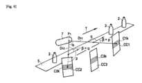
複数の感応素子のマトリクスを含む感応表面区域は、マトリクス又は二次元イメージセンサを構成し、マトリクスに分散された複数のX線感応素子のマトリクス配列を含む。図10に示されるように、この定義によれば、より大きな感応表面Ssに属する感応マトリクス表面C1、C1’も、マトリクスイメージセンサである。図10のこの例では、感応表面Ssは、マトリクス物理センサ要素CC1の感応表面に対応する。同じ表面を持つ複数の感応マトリクス表面C1、C1’は、場合によっては、取得装置によって別々に処理されうる。したがって、いずれにせよ、それらは、それぞれ異なる複数のマトリクス放射線画像M1、M1’を提供する複数のマトリクスイメージセンサを構成する(図12)。マトリクス放射線画像M1、M1’にそれぞれ関連付けられた投射方向D11、D11’は、画像の取得時に、焦点F1から始まり、感応マトリクス表面C1、C1’の中央を通り抜ける方向である。したがって、複数のイメージセンサC1、C1’は非分離領域であり、時間的に順次作動しうる。A sensitive surface area comprising a matrix of multiple sensitive elements constitutes a matrix or two-dimensional image sensor and comprises a matrix arrangement of multiple X-ray sensitive elements distributed in a matrix. According to this definition, as shown in FIG. 10, the sensitive matrix surfaces C1, C1' belonging to a larger sensitive surface Ss are also matrix image sensors. In this example of FIG. 10, the sensitive surface Ss corresponds to the sensitive surface of the matrix physical sensor element CC1. Multiple sensitive matrix surfaces C1, C1' with the same surface may possibly be processed separately by the acquisition device. They therefore in any case constitute multiple matrix image sensors providing multiple matrix radiation images M1, M1' respectively different (FIG. 12). The projection directions D11, D11' respectively associated with the matrix radiation images M1, M1' are directions starting from the focal point F1 and passing through the center of the sensitive matrix surfaces C1, C1' at the time of acquisition of the image. The multiple image sensors C1, C1' are therefore non-separate areas and may be operated sequentially in time.
もちろん、当業者は、シンチレータプレートが放射画像を受け取り、それを可視光線に変換する輝度増幅器又は「スクリーンキャプチャカメラ」に基づく物理マトリクスセンサ要素の技術を使用できる。シンチレータの背面で見える画像は、シンチレータの発光範囲、一般には可視範囲において、かつ、必要に応じて対物レンズを備えた感度カメラによって撮影される。Of course, those skilled in the art can use the technology of physical matrix sensor elements based on brightness amplifiers or "screen capture cameras" in which a scintillator plate receives the radiation image and converts it into visible light. The image seen on the back of the scintillator is captured by a sensitive camera in the emission range of the scintillator, generally in the visible range, and optionally equipped with an objective lens.
本発明は、機械加工、成型、吹き込み成型、焼結、射出成型、押し出し成型によって得られた複数の物体又は上記方法の種類に応じて得られた複数の物体のアセンブリなどの1つ又は複数の材料から構成された複数の製造物体のシリーズに適用される。上記物体のそれぞれは、1つ又は複数の異なる部分から作られており、部分の数は既知であり、各部分は減衰係数μが既知で均一な、つまり、物体の検査対象領域の検討された部分の任意の点において同じ値を有し、かつ、好ましくは、上記シリーズの複数の物体について時間が経過しても一定であって同一である、材料から作られている。The invention applies to a series of manufactured objects made of one or more materials, such as objects obtained by machining, molding, blow molding, sintering, injection molding, extrusion, or assemblies of objects obtained depending on the type of method. Each of said objects is made of one or more different parts, the number of parts being known, each part being made of a material whose attenuation coefficient μ is known and uniform, i.e. has the same value at any point of the considered part of the area to be examined of the object, and is preferably constant and identical over time for the objects of said series.
いくつかの実施形態では、例えば、鋼又はアルミニウムの鋳造工場で製造された機械部品、ガラス瓶、プラスチック梱包用容器、これらは、単一材料物体と呼ばれる物体であってもよい。この場合、減衰係数μは既知で均一、つまり、物体の検査対象領域の任意の点において同じ値を有する。ただし、本発明は、複数の多材料物体に対して実行されうる。場合によっては、異なる材料が等しい減衰係数を有するので、物体の異なる部分への細分化は無視でき、物体は、減衰係数が均一であるという条件の下、検査領域全体にわたって均一であるという意味で、それが単一材料物体であるとみなすことができる。In some embodiments, objects may be referred to as single-material objects, for example machine parts made in a steel or aluminum foundry, glass bottles, plastic packaging containers, etc. In this case, the attenuation coefficient μ is known and uniform, i.e. has the same value at any point of the area to be inspected of the object. However, the invention may be carried out for multiple multi-material objects. In some cases, different materials have equal attenuation coefficients, so that the subdivision of the object into different parts can be ignored and the object can be considered to be a single-material object in the sense that it is uniform throughout the inspection area, provided that the attenuation coefficient is uniform.
ただし、本発明は、複数の多材料物体の直線寸法の測定のためにも実行されうる。したがって、そのような物体は、組成が均一な体積のアセンブリからなるとみなされ、組成が均一な各体積は物体の一部とみなされる。これらの体積、又は物体の部分は、複数の閉曲面で区切られる。本発明では、少なくとも物体の検査対象領域について、これらの部分の数が既知であるとみなされる。この数は、検査領域について数えることができ、計算の重要性を制限し、かつ、反復調整方法を使用する場合の収束を維持するために、好ましくは小さく、例えば50未満、好ましくは20未満、より好ましくは10未満である。However, the invention can also be implemented for the measurement of linear dimensions of a number of multi-material objects. Such objects are therefore considered to consist of an assembly of volumes of homogeneous composition, each volume of homogeneous composition being considered as a part of the object. These volumes, or parts of the object, are bounded by a number of closed surfaces. In the present invention, the number of these parts is considered to be known, at least for the area to be examined of the object. This number can be counted for the examination area and is preferably small, for example less than 50, preferably less than 20, more preferably less than 10, in order to limit the importance of the calculations and to maintain convergence when using iterative adjustment methods.
好ましくは、物体のこれらの部分のトポロジー、すなわち特に関連するもの(共通の表面の存在、それらの間の異なる部分の包含又は除外の状況、並置及び相対的位置、共通の表面の存在など)の相対的位置、は既知である。これは、物体を通り抜けるX線は、異なるが既知の減衰係数を有する有限数の体積を通り抜け、したがって通り道は複数の線分に分割でき、各線分は物体の一部の複数の境界表面に属する2つの点を結合し、これらの線分の長さが事前に既知でなくても、一定の減衰の領域を通って走行するとみなされうるといっていることになる。各X線の減衰は、通過された連続する複数の線分の長さ及び各線分の減衰にのみ依存する。結果として、各放射線画像点における情報は、その構造が既知の検査領域の実際の複数の寸法に直接関連する。加えて、物体の構造、そして特にその異なる複数の部分の構造は、コンピュータによって事前に(測定前に)、物体の複数の境界表面と呼ばれる複数の閉曲面のセットから作られた図形によって記載されうる。物体の境界表面とは接触表面である。そのため、物体の1つ又は複数の外部境界表面を有することが可能であり、それぞれが周囲の空気と物体の一部の材料との接触面である。物体の1つ又は複数の内部境界表面を有することも可能であり、それぞれが物体の並置された2つの部分の2つの材料同士の接触面である。物体の内表面で区切られた内部空洞を含む中空物体の場合、内表面は、周囲の空気が閉じ込められる閉空洞の場合でも、物体の材料と周囲の空気との接触面であるので、内表面は物体の外部境界表面である。Preferably, the topology of these parts of the object, i.e. the relative positions of those that are particularly relevant (presence of common surfaces, the situation of inclusion or exclusion of different parts between them, juxtaposition and relative positions, presence of common surfaces, etc.), is known. This means that the X-rays passing through the object pass through a finite number of volumes with different but known attenuation coefficients, and therefore the path can be divided into line segments, each of which connects two points belonging to the boundary surfaces of a part of the object, and can be considered to run through an area of constant attenuation, even if the length of these line segments is not known in advance. The attenuation of each X-ray depends only on the length of the successive line segments passed and on the attenuation of each line segment. As a result, the information at each radiographic point is directly related to the actual dimensions of the examination area, the structure of which is known. In addition, the structure of the object, and in particular the structure of its different parts, can be described in advance (before the measurements) by a computer by a diagram made from a set of closed surfaces, called the boundary surfaces of the object. The boundary surfaces of the object are contact surfaces. Thus, an object may have one or more exterior boundary surfaces, each of which is an interface between the surrounding air and the material of one part of the object. An object may also have one or more interior boundary surfaces, each of which is an interface between two materials of two juxtaposed parts of the object. In the case of a hollow object that includes an interior cavity bounded by the object's interior surface, the interior surface is an exterior boundary surface of the object, since it is an interface between the material of the object and the surrounding air, even in the case of a closed cavity in which the surrounding air is trapped.
材料の減衰係数μは、厳密には、波長λ又はX線のエネルギーに依存するスペクトル特性μ(λ)であることに留意されたい。この特徴は、X線源が固有の放出されたスペクトル組成を有する限り、必ずしも考慮される訳ではなく、減衰μは、選択されたX線源のスペクトルに対する材料の特徴とみなされうる。当業者はまた、上記ビームのスペクトル減衰又は強化を考慮に入れるための任意の方法を使用して本発明を遂行する方法を知っているであろう。It should be noted that the attenuation coefficient μ of a material is strictly a spectral characteristic μ(λ) that depends on the wavelength λ or energy of the X-rays. This characteristic is not necessarily taken into account insofar as the X-ray source has a unique emitted spectral composition, and the attenuation μ can be considered as a characteristic of the material for the spectrum of the selected X-ray source. The skilled person will also know how to carry out the present invention using any method to take into account the spectral attenuation or enhancement of the beam.
もちろん、低振幅の減衰係数μの局所的及び/又は時間的変動により、上記方法の実行は妨げられないが、その振幅によっては、上記設備で行われる測定の精度がわずかに又は大幅に低下する可能性がある。したがって、例えば、複数の物体の組成における変動、製造方法のパラメータにおける変動、環境条件の変更、又は複数のX線源の動作における変化に起因する、そのようなわずかな変動は、検証された物体の各部分における材料の減衰量の独自性及び不変性を考慮して、起こりうるとみなされる。一方で、本発明は、不均一な粒子及び減衰が画像の解像度よりも大きい限り、粒径の粗い礫岩、小石を有するモルタルなどの物体の不均一な部分には適用されない。本発明は、手荷物など、形状及び内容が事前に未知の物体の検査には適用されない。同じ理由から、本発明は、基準を満たす物体を除いて、一般に医用又は生体画像化には適用されない。Of course, local and/or temporal variations of the attenuation coefficient μ of low amplitude do not prevent the execution of the method, but depending on their amplitude, they may slightly or significantly reduce the accuracy of the measurements made in the installation. Such slight variations, for example due to variations in the composition of the objects, variations in the parameters of the manufacturing method, changes in the environmental conditions or changes in the operation of the X-ray sources, are therefore considered possible, taking into account the uniqueness and constancy of the material attenuation in each part of the examined object. On the other hand, the invention does not apply to heterogeneous parts of objects such as coarse-grained conglomerates, mortar with pebbles, etc., as long as the heterogeneous grains and attenuation are greater than the resolution of the image. The invention does not apply to the inspection of objects whose shape and contents are unknown in advance, such as baggage. For the same reason, the invention does not apply in general to medical or biomedical imaging, except for objects that meet criteria.
空気の減衰量は材料の減衰量と比較して無視できるほどであるとみなされうる。この場合、物体を通り抜けるX線ビームの減衰量は、一方では、放出されたX線スペクトルの上記均一な減衰量のみに依存し、他方では、通過された材料の累積厚さのみに依存するであろう。あるいは、すべての光線について、通過された空気の厚さが大きくかつ均一であるとみなされ、そのため、それは既知とみなされうる。空気による減衰量は、測定された減衰量の合計から差し引かれうる。そのため、例えば、任意に補正された各放射線画像におけるグレーレベルは、通過された材料の累積厚さの合計にのみ直接的に依存するとみなされうる。その結果、空気と物質との遷移部である複数の境界表面を正確に特定することが可能となる。The attenuation of the air can be considered to be negligible compared to the attenuation of the material. In this case, the attenuation of the X-ray beam passing through the object will depend only on the uniform attenuation of the emitted X-ray spectrum, on the one hand, and only on the cumulative thickness of the material passed through, on the other hand. Alternatively, the thickness of the air passed through can be considered to be large and uniform for all rays, and therefore known. The attenuation due to the air can be subtracted from the total measured attenuation. Thus, for example, the grey level in each optionally corrected radiographic image can be considered to depend directly only on the total cumulative thickness of the material passed through. As a result, it becomes possible to accurately identify several boundary surfaces, which are the transitions between air and matter.
したがって、物体の複数の放射線画像のデジタル分析により、物体の複数の境界表面の特定の数の点の空間内の相対的位置を知ることができる。Thus, digital analysis of multiple radiographic images of an object can reveal the relative positions in space of a specific number of points on multiple boundary surfaces of the object.
各物体の複数の放射線画像のデジタル分析により、場合によっては、以下の説明ではデジタル幾何モデルと呼ばれる、各物体の三次元デジタル幾何モデルを構築することが可能となる。任意に、このデジタル幾何モデルは、単に複数の二次元デジタル幾何モデルの積み重ねでありうる。デジタル幾何モデルの作成とは、数学的な、図式的な及びデータ構造の用語における手法であって、この手法においては、複数の三次元物体は、コンピュータシステムのメモリ内においてデジタル形式で表現され、処理される。本発明が、これらの実施形態のいくつかにおいて、複数の放射線撮影物体と同じ数の三次元デジタル幾何モデルを特定することを可能であり、かつ、輸送システム上を走行する複数の物体の数と同じ数の放射線撮影物体が存在していてもよいとみなされるべきである。実際、本発明の特徴は、必要ならば、高速の場合を含めて、上記設備内を循環する複数の物体のそれぞれの測定を行うことを可能とすることである。The digital analysis of the multiple radiographic images of each object allows, in some cases, the construction of a three-dimensional digital geometric model of each object, referred to in the following description as a digital geometric model. Optionally, this digital geometric model may simply be a stack of multiple two-dimensional digital geometric models. The creation of a digital geometric model is a technique in mathematical, graphical and data structure terms, in which multiple three-dimensional objects are represented and processed in digital form in the memory of a computer system. It should be considered that the invention in some of these embodiments allows as many three-dimensional digital geometric models to be specified as there are multiple radiographic objects, and that there may be as many radiographic objects as there are multiple objects traveling on the transport system. In fact, a feature of the invention is that it allows measurements to be made of each of the multiple objects circulating in the facility, including at high speeds, if necessary.
複数の放射線画像から直接、つまり体積モデルの計算を行うことなく、表面モデルを得ることが可能である。It is possible to obtain a surface model directly from multiple radiographic images, i.e. without calculating a volume model.
表面モデリングにおいて、物体は少なくとも1つの三次元表面、特に、物体の材料と外部環境(通常は空気)との間の外部境界表面に対応する閉じた三次元配向表面、によって定義され、これにより、物体の内部及び外部の概念を理解することが可能となる。陰関数曲面、パラメータ化された曲面(平面部分、Bスプライン、NURBSなど)のような表面には、様々なモデリングが可能であり、場合によっては、複数の曲線の配列によって制限される。単純なモデリングは三角形メッシュであり、それは、複数の四面体によって形成された体積の境界表面としてみなされうる。In surface modeling, an object is defined by at least one three-dimensional surface, in particular a closed three-dimensional oriented surface corresponding to the external boundary surface between the object's material and the external environment (usually air), which allows for a conceptual understanding of the interior and exterior of the object. There are various modeling possibilities for surfaces such as implicit surfaces, parameterized surfaces (planar sections, B-splines, NURBS, etc.), sometimes constrained by an arrangement of multiple curves. A simple modeling is a triangular mesh, which can be considered as the boundary surface of a volume formed by multiple tetrahedrons.
三次元物体の断面、つまり物体と断面平面との交差部分により、断面平面における物体の描写を定義することが可能となる。物体の複数の三次元表面の断面、したがってその複数の境界表面の断面は、断面平面における1つ又は複数の二次元曲線を特定し、それらは、一緒になって、断面平面における物体の描写を形成する。一連の複数の切断平面におけるこれらの複数の二次元曲線の情報により、もちろん複数の断面平面の数に依存する精度で、複数の三次元表面の再構築が可能となる。The cross-sections of a three-dimensional object, i.e. the intersections of the object with the cross-sectional planes, make it possible to define the representation of the object in the cross-sectional plane. The cross-sections of the object's three-dimensional surfaces, and therefore of its bounding surfaces, specify one or more two-dimensional curves in the cross-sectional plane, which together form the representation of the object in the cross-sectional plane. Knowledge of these two-dimensional curves in a series of cutting planes allows the reconstruction of three-dimensional surfaces, with an accuracy that of course depends on the number of cross-sectional planes.
長さなどの直線寸法の測定を行うには、いくつかの手法がある。There are several techniques for measuring linear dimensions such as length.
表面方法と呼ばれる方法では、線分であって、その両端が直線と表面モデルの材料/空気の境界表面との交差部分である線分を計算することが可能である。最後に、混合方法は、体積モデルを表面モデルに変換することと、その後、上記第2の方法を適用することとを含む。In a method called the surface method, it is possible to calculate a line segment whose both ends are the intersections of a straight line with the material/air boundary surface of the surface model. Finally, the mixed method involves converting the volume model into a surface model and then applying the second method described above.
第3の方法は、1つ又は2つの二次元曲線の2点間の距離を、切断平面で特定することを含み、上記曲線は物質と空気との境界である。The third method involves determining the distance between two points on one or two two-dimensional curves at a cutting plane, the curves being the material-air boundary.
三次元点とは、その座標が任意の基準軸内において、三次元空間で知られる点である。A 3D point is a point whose coordinates are known in three-dimensional space within any reference axis.
これらの3つの上述の方法は、2つの三次元点の間の距離を特定して、直線寸法を特定する方法の例である。These three above mentioned methods are examples of how to determine the distance between two 3D points and therefore determine the linear dimension.
本発明の1つの目的は、単純な複数の二次元放射線画像により可能とされていたよりも完全な測定を行うことである。実際、マトリクスイメージセンサを使用して、検査領域の投射に対応する二次元放射線画像を得て、「投射平面」と呼ばれる投射方向に直交する平面における複数の寸法を測定することは容易である。同様に、リニアイメージセンサを使用して、移動方向での移動中に取得された連続する複数の画像の列の並置により得られた検査領域の投射に対応する二次元放射線画像を得て、移動方向に平行な投射平面における複数の寸法を測定することは容易である。一方、本発明によれば、複数の投射平面に含まれず、複数の投射平面に平行でもない複数の方向における複数の直線寸法を測定できる。本発明に係る方法は、実際には、少なくとも3つの異なる投射方向における複数の放射線画像の組み合わせを処理する際に、実質的に全ての方向において複数の寸法を再構築及び測定することを含みうる。これは、物体の検査対象領域に含まれる境界表面に属する空間内の複数の三次元点の特定を可能にする任意の方法によって可能である。表面若しくは体積タイプの、又は複数の切断平面に基づく、検査対象領域の三次元モデルの再構築は、1つの取りうる方法である。実際、検査対象領域の三次元体積モデルから間接的に、及び、好ましくは検査対象領域の三次元表面モデルから、場合によっては上記領域の三次元モデルの複数の断面を特定することによって、複数の二次元放射線画像だけからでは測定不能な複数の方向に沿って分布した少なくとも2つの三次元点を、より好ましくは複数の三次元点群を、特定することが可能となる。One object of the invention is to perform a more complete measurement than would be possible with a simple plurality of two-dimensional radiographic images. In fact, it is easy to use a matrix image sensor to obtain a two-dimensional radiographic image corresponding to a projection of an examination area and to measure the dimensions in a plane perpendicular to the projection direction, called the "projection plane". Similarly, it is easy to use a linear image sensor to obtain a two-dimensional radiographic image corresponding to a projection of an examination area obtained by juxtaposing a series of successive images acquired during a movement in the movement direction and to measure the dimensions in a projection plane parallel to the movement direction. On the other hand, according to the invention, it is possible to measure linear dimensions in directions that are not included in the projection planes and are not parallel to the projection planes. The method according to the invention may in fact include reconstructing and measuring dimensions in substantially all directions when processing a combination of multiple radiographic images in at least three different projection directions. This is possible by any method that allows the identification of multiple three-dimensional points in space that belong to a boundary surface included in the examination area of the object. The reconstruction of a three-dimensional model of the examination area, of surface or volume type or based on multiple cutting planes, is one possible method. Indeed, by indirectly identifying a three-dimensional volume model of the area to be examined, and preferably from a three-dimensional surface model of the area to be examined, and possibly from multiple cross sections of the three-dimensional model of said area, it is possible to identify at least two three-dimensional points, and more preferably multiple three-dimensional point clouds, distributed along multiple directions that cannot be measured from multiple two-dimensional radiographic images alone.
したがって、デジタル幾何モデルは、点、線分、曲面、表面のような複数の幾何学的要素で構成され、デジタル幾何モデルが、理想的な物体に比べてゆがみを有する実際の物体の構造の忠実な図形となるように、各要素を計算するために、実際の物体上の点を通り抜けたX線の少なくとも一部の減衰量を考慮することによって複数の放射線投射から計算される。換言すると、複数の幾何学的要素の座標は、複数の2D放射線投射のどれにおいてもこれらの幾何学的要素を区別することができない場合でさえも、上記座標が複数の放射線投射を補正したことを考慮することによって特定される。したがって、デジタル幾何モデル上の複数の寸法測定は、複数の放射線投射のどれにおいても区別することができない複数の幾何学的要素から、モデル化された各物体の複数の寸法の情報を与える。Thus, the digital geometric model is composed of a number of geometric elements, such as points, lines, curves, surfaces, which are calculated from a number of radiation projections by taking into account at least a partial attenuation of the X-rays passing through the points on the real object, so that the digital geometric model is a faithful representation of the structure of the real object with distortions compared to the ideal object, in order to calculate each element. In other words, the coordinates of the geometric elements are identified by taking into account that said coordinates have been corrected for the number of radiation projections, even if these geometric elements cannot be distinguished in any of the number of 2D radiation projections. Thus, a number of dimensional measurements on the digital geometric model give information of the dimensions of each modeled object from the geometric elements that cannot be distinguished in any of the number of radiation projections.
結果として、本発明に係る方法の1つの利点は、各物体について、少なくとも2つの三次元点であって、それぞれが検査対象領域の境界表面に属する三次元点を含むデジタル幾何モデルを、これらの2つの点が投射方向Dji、Djikに直交する平面に配置されず、移動方向に平行な平面にも配置されない場合でも、特定することを可能とすることである。As a result, one advantage of the method according to the invention is that it makes it possible to identify for each object a digital geometric model comprising at least two three-dimensional points, each of which belongs to the boundary surface of the area to be examined, even if these two points are not located in a plane perpendicular to the projection directions Dji, Djik, nor in a plane parallel to the direction of movement.
もちろん、上記方法の利点は、投射方向Dji、Djikに直交する平面以外の、かつ、移動方向に平行な平面以外の複数の方向における複数の測定値を提供することだけでなく、検査領域に分布された多数の測定値を、それゆえに、複数の一対の点の間で、多方向における寸法を提供することである。好ましくは、デジタル幾何モデルは、
それぞれが検査対象領域の境界表面に属し、かつ投射方向Dji、Djikに直交する平面に位置せず、かつ、移動方向Tと平行な平面に位置しない、空間内の少なくとも2つの三次元点、
及び/又は、投射方向Dji、Djikに直交する平面に属さず、かつ、移動方向Tに平行な平面に属さない複数の点を含む、検査対象領域の少なくとも1つの三次元表面、
及び/又は、投射方向Dji、Djikに直交する平面と異なり、かつ、上記移動方向に平行な平面と異なる平面に沿った、検査対象領域の少なくとも1つの断面、
から構成される。 Of course, the advantage of the method described above is that it not only provides multiple measurements in multiple directions other than the plane perpendicular to the projection directions Dji, Djik and parallel to the direction of movement, but also provides a large number of measurements distributed in the examination area, and therefore dimensions in multiple directions, between multiple pairs of points. Preferably, the digital geometric model is
At least two three-dimensional points in space, each of which belongs to a boundary surface of the area to be examined and which are not located in a plane perpendicular to the projection directions Dji, Djik and are not located in a plane parallel to the movement direction T,
and/or at least one three-dimensional surface of the area to be examined, the surface including a number of points not belonging to a plane perpendicular to the projection directions Dji, Djik and not belonging to a plane parallel to the movement direction T;
and/or at least one cross-section of the area to be examined along a plane different from the plane perpendicular to the projection directions Dji, Djik and different from the plane parallel to the direction of movement,
It consists of:
「推測的」幾何モデルと呼ばれる幾何モデルは、複数の物体のシリーズのデジタル幾何モデルであって、物体のデジタル幾何モデルを構築するための再構築ソフトウェアの初期設定として機能する。その役割は主に、物体の形状、構造及び寸法、及び/又は計算によるモデル化対象物体の異なる複数の部分についての情報をコンピュータシステムに提供することである。ただし、この情報は、測定に必要な精度で物体を測定するには正確さが不十分である。A geometric model, called an "abductive" geometric model, is a series of digital geometric models of objects that serve as the initial setting for the reconstruction software to build a digital geometric model of the object. Its role is mainly to provide the computer system with information about the shape, structure and dimensions of the object and/or about the different parts of the object to be modeled by calculation, but this information is not accurate enough to measure the object with the required accuracy.
この情報により、特に、
複数の放射線画像から、材料のない空の画像空間の複数の領域における減衰量を、そこでは減衰量はゼロとみなされるため、推測的にモデル化しないこと、
及び/又は、
複数の放射線画像から、寸法の測定が行われるべき複数の表面のみを、モデル化すること、
及び/又は、
複数の放射線画像からモデル化された複数の表面と、複数の理論上の理想表面との間の偏差のみを特定すること、
が可能となる。 This information will enable us, inter alia:
not a priori modeling attenuation in regions of empty image space where no material is present from multiple radiographic images, since the attenuation there is assumed to be zero;
and/or
modeling only the surfaces from the radiographic images for which dimensional measurements are to be taken;
and/or
Identifying only deviations between a plurality of surfaces modeled from a plurality of radiographic images and a plurality of theoretical ideal surfaces;
This becomes possible.
単一材料物体の場合、推測的幾何モデルの情報により、推測的モデルに応じた材料を含む画像空間の複数の領域における減衰値を、それは物体の製造材料の減衰値として知られているので、複数の放射線画像から特定しないことも可能である。In the case of a single-material object, the knowledge of the a priori geometric model makes it possible not to determine from the multiple radiographic images the attenuation values in multiple regions of the image space that contain the material according to the a priori model, since these are known as the attenuation values of the manufacturing material of the object.
ただし、このモデルは上記物体とは無関係に知られており、非現実的な理論上の理想物体を表しているので、本発明によれば、推測的幾何モデルの測定値から物体の測定値は推測されないことを理解されたい。However, it should be understood that, since this model is known independently of the object and represents an unrealistic theoretical ideal object, measurements of the object are not inferred from measurements of the a priori geometric model in accordance with the present invention.
図面から、より具体的には図1及び2から分かるように、本発明の目的は、高速走行で移動する複数の製造物体2の複数の直線寸法の測定を自動的に行うための方法の実行を可能とする設備1に関する。本発明は、複数の物体の品質の又は変形若しくは製造方法の質を検査するための、変形又は製造ステップの後の、複数の製造物体のシリーズの「インライン」検査と呼ばれる検査に関し、1シリーズの複数の物体は、本来ならば同一であるはずである。異ならせるための意図的な動作が取られない限り、複数の物体は、本来ならば同一であるはずである。ただし、変形又は製造における偶然のせいで、1シリーズにおいて、複数の物体のすべてが同一ではないことがよく知られている。As can be seen from the drawings, and more particularly from figures 1 and 2, the object of the invention is an
上記方法は、物体2のフローの走行レートに対して動作する。理想的には、設備1は、例えば毎分100物体を超える、好ましくは毎分300物体を超える生産レートで、そして、例えば毎分少なくとも600物体のレートで、生産物を処理する能力がある。The method operates on a running rate of the flow of
ただし、計算時間は2つの物体の間の時間間隔を超えていてもよい。同様に、積分時間とも呼ばれる、画像及び複数の読み取りセンサの露光時間が長すぎてもよい。本発明に係る単一の設備によって、最速のフローを処理することができない場合、それぞれが生産物の一部を検査する、複数の設備を並行して実装することができる。そのため、本発明に係る2つ又は3つの設備によって検査された2つ又は3つの平行なフローに、生産フローを分割することが可能である。いうまでもなく、フローの数が、よって本発明に係る設備の数が少ない場合には、本発明の経済的利益が増加する。However, the calculation time may exceed the time interval between two objects. Similarly, the exposure time of the image and the multiple reading sensors, also called the integration time, may be too long. If the fastest flow cannot be handled by a single installation according to the invention, multiple installations can be implemented in parallel, each inspecting a part of the production. It is therefore possible to divide the production flow into two or three parallel flows inspected by two or three installations according to the invention. It goes without saying that the economic benefits of the invention increase if the number of flows and therefore the number of installations according to the invention is small.
本発明は、生産速度に適合しない回転板上のヘリカルスキャン及びスキャンを避けることによって、走行する複数の物体を測定することにより、著しい改善をもたらすものである。これらの2つの撮影手段は、複数の焦点及び/又は複数のセンサに対する複数の物体の相対的な回転を伴い、上記設備内の複数の物体の「走行の中断」又は非常に遅い移動を引き起こすからである。The present invention provides a significant improvement by avoiding helical scanning and scanning on a rotating plate that are not compatible with production speeds, as these two imaging methods involve relative rotation of the objects to multiple focal points and/or multiple sensors, causing "stops in the run" or very slow movement of the objects in the facility.
本発明に係る方法は、好ましくは各物体2について、少なくとも1つの、そして一般には複数の直線寸法、つまり複数の長さの測定を確保する。直線寸法とは、実際には1つの線に沿って測定された長さである。この線は、それに沿って直線寸法が測定され、直線的な線、又は非直線的な線、例えば任意の曲線、環状線、破線などでありうる。この線は、平面に含まれる平面線、又は平面に含まれない三次元線でありうる。長さとは、例えばインチ又はメートルなど、長さの単位で表される測定値である。製造物体の直線寸法は、例えば直径、厚さ、高さ、長さ、幅、深さ、距離、原点から点までの距離としての座標、製造物体の外周である。検査領域の少なくとも1つの直線測定値とは、少なくとも2つの三次元点の間の距離であり、これらの三次元点は、それぞれが検査対象領域の境界表面、特に外部境界表面に属し、境界表面は投射方向Dji、Djikに直交しない平面を含む、平面に配置される。The method according to the invention ensures, preferably for each
本発明によれば、複数の物体2とは、複数の物体の1シリーズを構成し、上記寸法変動を除いて、本来ならば同一の物体であるはずである。換言すると、1シリーズは、複数の物体が一致する場合、理論的に同一の複数の物体で構成される。寸法検査は、実際の複数の寸法を測定することと、これらの寸法を要求される複数の寸法と比較することとを含む。推測的に、1シリーズのどの物体も、要求される複数の寸法を有する理想的な基準物体に近いが、寸法変動によってそこから外れている。According to the invention, the
1つの有利な実施形態の特徴によれば、物体2の少なくとも1つの領域が、検査対象として選択されるので、物体のこの領域における寸法測定を、検査対象領域の寸法特徴に対応させて、行うことができる。少なくとも、1つ又は複数の直線寸法が測定される物体の領域は、複数のX線によって検査される。そのため、検査領域は、物体全体に又はその物体の1つ又は複数の領域に、対応しうる。According to a feature of one advantageous embodiment, at least one region of the
先に述べたように、1シリーズの全ての物体2は、単一の部分から、又は複数の異なる部分からなり、各部分は、物体の検討された部分の任意の点で均一な減衰係数を有する材料で作られている。As mentioned before, all
本発明の1つの有利な変形例によれば、検査対象領域の各部分について、この係数はコンピュータシステムによって知られている。上記方法は、材料の減衰係数の値をコンピュータシステムに利用可能とするための手段を提供しうる。この値は、材料の特性であって、この材料と放射線との相互作用を定義し、かつ、放射線の波長に依存する値という意味では、スペクトルでありうる。この値は、放射線の波長に依存しないという意味では、非スペクトルでありうる。この値は、X線源の設定に応じて決定されうる。上記提供は、異なる複数の入力、通信及び記憶装置によって可能になる。例えば、材料の減衰係数の値をコンピュータシステムに利用可能とするための装置は、大容量メモリ、有線若しくは無線のコンピュータネットワーク、又はマン/マシンインターフェースである。According to one advantageous variant of the invention, for each part of the area to be examined, this coefficient is known by the computer system. The method may provide means for making the value of the attenuation coefficient of the material available to the computer system. This value may be spectral, in the sense that it is a property of the material, defines the interaction of this material with the radiation and is dependent on the wavelength of the radiation. This value may be non-spectral, in the sense that it is independent of the wavelength of the radiation. This value may be determined depending on the settings of the X-ray source. The provision is made possible by different input, communication and storage devices. For example, devices for making the value of the attenuation coefficient of the material available to the computer system are mass memories, wired or wireless computer networks or man/machine interfaces.
設備1はまた、搬送平面PCで、すなわち移動ベクトルTによって具体化された方向で、平らな軌道に沿って、複数の物体2を輸送するための装置5を含む。好ましくは、上記軌道は直線的であり、搬送線の真直度に通常許容される範囲内にある。通常、輸送装置5は、その中に配置された複数の物体2の直線移動を確保するウェブ又はチェーンコンベアである。そのため、同じシリーズの複数の物体2は、搬送平面PCにおいて本質的に並進運動状態にある。図1及び2にさらに具体的に示されるように、この説明の便宜のために、複数の物体2の移動方向は、基準軸X、Y、Zのうち水平軸Xに沿って確立され、基準軸X、Y、Zは、水平軸Xに垂直な垂直軸Zと、垂直軸Zに垂直な横軸Yと、水平軸Xとを含み、X及びYは、搬送平面PCに平行な平面にあり、好ましくは、必須ではないが、水平であることが、通常は前提である。The
方向Tに沿って並進運動する正規直交基準軸内において検討された複数の物体の位置は、それらの移動及び複数の放射線画像の取得中に、固定される。この固定位置は、特に方向Tに沿って並進運動する正規直交基準軸内において物体の回転がないこと、特に例えば物体の取りうる対称軸を中心とする物体の回転がないこと、を意味する。例えば、複数の物体はコンベヤバンド上に、安定を保って、場合によっては、容器の底部又は台座の脚などのきれいな載置平面上に載せられる。The positions of the considered objects in the orthonormal reference axes translating along the direction T are fixed during their movement and the acquisition of the radiographic images. This fixed position means in particular that there is no rotation of the objects in the orthonormal reference axes translating along the direction T, in particular for example no rotation of the objects around a possible axis of symmetry of the objects. For example, the objects are placed on a conveyor band, stably and possibly on a clean resting surface such as the bottom of a container or the foot of a pedestal.
本発明の1つの変形例では、複数の物体2の支持部を提供することが可能である。この場合、この支持部は、方向Tに沿って並進運動する正規直交基準軸に固定され、方向Tに沿って並進運動する正規直交基準軸にも固定された物体を維持する。支持部が測定値に影響を与えないように、第1の変形例によれば、それは検査領域から除外されるので、複数の投射における検査領域の重ね合わせには現れない。第2の変形例によれば、その減衰係数は、複数の物体の減衰係数に対して無視できるほどであり、空気に又は減衰量ゼロに同化されうる。第3の有利さで劣る変形例によれば、支持部の構造、及び運動する基準軸におけるその位置は、複数の物体のシリーズについて正確に知られ、かつ再現可能であり、そして、その減衰係数は正確に知られ、かつ安定しており、好ましくは複数の物体のシリーズからの複数の物体の減衰係数と同一であるので、支持部は再構築において考慮され、かつ、物体の幾何モデルから分離される。In one variant of the invention, it is possible to provide a support for the plurality of
複数の物体の位置が安定している場合(複数のX線画像のスクロール及び取得中に)、方向Tに沿って並進運動する正規直交基準軸におけるこの位置もまた、複数の物体の1シリーズの各物体について同じであることが好ましい。If the position of the objects is stable (during scrolling and acquisition of multiple X-ray images), then this position in the orthonormal reference axis translating along direction T is also preferably the same for each object in a series of objects.
これに当てはまらない場合、本発明の1つの変形例によれば、上記設備の共通の基準軸に対して方向Tに沿って並進運動する正規直交基準軸における各物体の位置を特定するための手段を実行することが可能であり、上記位置は、例えば後述する複数の断面平面における物体の描写を計算するための手段によって考慮される。この予備ステップは、各物体の位置を特定することを含む。それは、仮想基準軸において、例えば推測的幾何モデルに由来しうる、物体の複数の推測的描写で取得された複数の画像を照合することを含みうる。これは、全ての場合において、方向Tに沿って並進運動する正規直交基準軸において、複数の物体の複数の描写を、場合によってはそこから取り出される複数の物体の3Dモデルを特定することを意味する。If this is not the case, according to one variant of the invention, it is possible to implement means for determining the position of each object in an orthonormal reference axis translating along a direction T relative to a common reference axis of the installation, said position being taken into account, for example, by means for calculating the representations of the object in a number of cross-sectional planes, as described below. This preliminary step involves determining the position of each object, which may involve matching, in a virtual reference axis, a number of images acquired with a number of a priori representations of the object, which may for example originate from an a priori geometric model. This means in all cases determining, in an orthonormal reference axis translating along a direction T, a number of representations of the objects, possibly 3D models of the objects taken therefrom.
一方、複数の物体の位置が、複数の放射線画像のスクロール及び取得中に方向Tに沿って並進運動する正規直交基準軸において安定している場合、上記設備の共通の基準軸に対する各物体の位置を特定する必要はないことが理解される。On the other hand, it will be appreciated that if the positions of the multiple objects are stable in orthonormal reference axes that translate along direction T during scrolling and acquisition of the multiple radiographic images, it is not necessary to determine the position of each object relative to a common reference axis of the above-mentioned equipment.
図4にさらに具体的に示されるように、直線移動中に、複数の物体2は、搬送体積Vtと呼ばれる体積を生成又は通り抜ける。平面PSは、搬送体積Vtの割線平面であり、搬送平面PCに直交し、かつ、移動方向Tに平行である。例えば、平面PSは搬送体積Vtを2つの等しいサブ体積に分割する正中平面でありうる。割線平面PSは、搬送平面が水平である場合、垂直平面である。As shown more specifically in FIG. 4, during linear movement, the
設備1はまた、図1及び2に示されるように、X線発生管7の少なくとも1つの焦点Fj(jは1からNFまで変わる)を含み、焦点Fjは、搬送体積Vtを通り抜けるように、より具体的には、物体2の少なくとも検査対象領域を通り抜けるように向けられた発散X線ビームを生成する。図5及び6に示されるように、上記設備が複数の焦点Fjを含む変形例では、本発明に係る方法で使用される全ての焦点は、直線軌道に沿った移動方向Tに平行な、同一の基準直線B上に配列される。これは、他の複数の画像の取得に使用されうる1つ又は複数の補助的焦点(図示せず)の存在をもたらしうる状況を妨げるものではない。The
設備1はまた、複数のイメージセンサCi、Cik(iは1からNまで変わり、Nは、場合によっては、3以上でありうる)を含み、イメージセンサCi、Cikは、複数のX線に感度を持ち、かつ、焦点Fjに由来する複数のX線に曝されるように配置されており、X線は、搬送体積Vtを、より具体的には少なくとも物体2の検査対象領域を通り抜ける。もちろん、1つ又は複数の管7及び複数のイメージセンサCi、Cikは、搬送体積Vtの外側に配置されるので、この体積内において複数の物体は自由な移動が可能である。通常、複数のX線発生管7及び複数のイメージセンサCi、Cikは、X線密封容器内に置かれている。The
いくつかの実施形態では、イメージセンサCi、Cikは、上記方法の実行において、このイメージセンサCiが、それが提供するとともに上記方法で考慮された複数の画像が、関連付けられた焦点Fjに由来する複数の光線のみで構成されるように提供されるという意味においては、単一の焦点Fjに関連付けられる。例えば、上記設備は、所定の焦点に由来する複数の光線のみが、例えば、適切な方法での複数の吸収マスクの配置によって、関連付けられたイメージセンサに到達できるように提供されうる。先の例と組み合わせられうる別の例によれば、イメージセンサによる複数の画像の取得は、単一の関連付けられた焦点のみが作動したときにのみトリガされることが提供されうる。In some embodiments, an image sensor Ci, Cik is associated with a single focal point Fj in the sense that, in the execution of the method, this image sensor Ci is provided such that the images it provides and considered in the method consist only of rays originating from the associated focal point Fj. For example, the facility may be provided such that only rays originating from a given focal point can reach the associated image sensor, for example by arranging absorbing masks in a suitable manner. According to another example that may be combined with the previous one, it may be provided that the acquisition of images by the image sensor is triggered only when only a single associated focal point is activated.
しかし、いくつかの実施形態では、複数のイメージセンサを同じ焦点Fjに関連付けることができ、及び/又は複数の焦点Fjを同じイメージセンサに関連付けることができる。1つの好ましい実施形態では、複数のイメージセンサが同じ焦点Fjに関連付けられる。However, in some embodiments, multiple image sensors may be associated with the same focal point Fj and/or multiple focal points Fj may be associated with the same image sensor. In one preferred embodiment, multiple image sensors are associated with the same focal point Fj.
上述したように、イメージセンサCi、Cikは、物理センサ要素CC1、CC2、・・・、CCnmax、・・・に、物理センサ要素の1つの部分に、又は1つ又は複数の物理センサ要素の複数の部分のアセンブリに対応する。As described above, image sensors Ci, Cik correspond to physical sensor elements CC1, CC2, ..., CCnmax, ..., to one portion of a physical sensor element, or to an assembly of multiple portions of one or more physical sensor elements.
焦点Fjに由来する複数のX線ビームは、少なくとも検査領域を通り抜け、そして、イメージセンサ上に、投射方向Dji、Djikに沿って、検査領域の放射線投射を形成する(図1及び2)。投射方向Dji、Djikは、焦点Fjから始まり、上記取得のために実装されたイメージセンサCi、Cikの中心を通り抜けるベクトルの配向方向である。1つ又は複数の焦点Fj及び複数のイメージセンサCi、Cikは、各イメージセンサが検査対象領域の放射線投射を受け取るように投射方向に沿って配置されている。The multiple X-ray beams originating from the focal point Fj pass through at least the examination area and form radiation projections of the examination area on the image sensor along projection directions Dji, Djik (Figures 1 and 2). The projection directions Dji, Djik are the orientation directions of vectors starting from the focal point Fj and passing through the centers of the image sensors Ci, Cik implemented for said acquisition. The one or more focal points Fj and the multiple image sensors Ci, Cik are arranged along the projection directions such that each image sensor receives a radiation projection of the examination area.
設備1はまた、移動中の各物体2について、その物体の複数の一次元処理用放射線画像のセットを取得するために、複数のイメージセンサCi、Cikに接続された取得システムを含み、各一次元処理用放射線画像は、基準直線Bを含む断面平面Pkに沿ったその物体の断面の投射を含む。より具体的には、この画像のセットは、
基準直線を含むNK個の異なる断面平面Pkについてのそのような複数の一次元処理用放射線画像と、
異なる各断面平面Pkについて、断面平面Pkにおいて少なくとも3つの異なる投射方向Djikに沿って得られた、検査対象領域のNP個のそのような一次元処理用放射線画像Spk、Sp’k、Sp’’k、・・・と、
を含む。 The
A plurality of such one-dimensional processing radiation images for N K different cross-sectional planes P k including the reference line;
for each different cross-sectional plane Pk, N P such one-dimensional processing radiation images Spk, Sp'k, Sp''k, ... of the area to be examined, obtained along at least three different projection directions Djik in the cross-sectional plane Pk;
Includes.
したがって、複数の画像のこのセットは、基準直線を含む複数の断面平面における各断面平面Pkについて、その物体の検査対象領域の少なくとも3つの一次元処理用放射線画像Spkを含み、これらはそれぞれが、断面平面Pkにおける異なる投射方向Djikに沿って得られる。Thus, this set of images includes, for each cross-sectional plane Pk in the cross-sectional planes that include the reference line, at least three one-dimensional processing radiation images Spk of the area to be examined of the object, each of which is obtained along a different projection direction Djik in the cross-sectional plane Pk.
図2は、基準直線Bを含み、そのため焦点Fjを含む複数の異なる断面平面Pk、Pk’の跡を示している。複数の異なる焦点Fjを含む実施形態では、これらの焦点は同一の基準直線B上に配置されるので、所定の断面平面Pk、Pk’、Pk’’、・・・は、すべての焦点Fjを含むことに留意されたい。異なる断面平面Pk、Pk’、・・・は、定義上は、互いに平行ではなく、基準直線Bの周囲に扇形に配列されていることに留意されたい。したがって、基準直線Bは、すべての断面平面Pkの交差部分であって、複数の平面のファミリーを構成する。2 shows the traces of different cross-sectional planes Pk, Pk' that include the reference line B and therefore the focal point Fj. Note that in an embodiment that includes different focal points Fj, these focal points are located on the same reference line B, so that a given cross-sectional plane Pk, Pk', Pk'', ... includes all the focal points Fj. Note that the different cross-sectional planes Pk, Pk', ... are by definition not parallel to each other, but are arranged in a fan shape around the reference line B. The reference line B is therefore the intersection of all the cross-sectional planes Pk, constituting a family of planes.
したがって、断面平面Pkは、基準直線Bによって、及びこの断面平面Pkに含まれるイメージセンサの少なくとも1つの感応素子Cik、Ci’k、Ci’’k、・・・によって、及び/又は、図9の例では、この断面平面Pkに含まれている、リニアイメージセンサCik、Ci’k、Ci’’k、・・・によって、定義される。リニアセンサの場合、それは、基準直線Bに平行に向けられてもよく、基準直線Bと交差する方向に沿って向けられてもよい。基準直線Bが設置のために固定されているので、断面平面Pkは、断面平面Pkに含まれたこの感応素子Cikに、又は断面平面Pkに含まれたこのリニアイメージセンサCikに、関連付けられる。したがって、断面平面Pkの少なくともいくつかについて、断面平面は物体2を切断しうる。Thus, the cross-sectional plane Pk is defined by a reference straight line B and by at least one sensitive element Cik, Ci'k, Ci''k, ... of the image sensor included in this cross-sectional plane Pk and/or, in the example of FIG. 9, by the linear image sensor Cik, Ci'k, Ci''k, ... included in this cross-sectional plane Pk. In the case of a linear sensor, it may be oriented parallel to the reference straight line B or along a direction intersecting the reference straight line B. Since the reference straight line B is fixed for installation, the cross-sectional plane Pk is associated with this sensitive element Cik included in the cross-sectional plane Pk or with this linear image sensor Cik included in the cross-sectional plane Pk. Thus, for at least some of the cross-sectional planes Pk, the cross-sectional plane may cut the
断面平面Pkの物体2との交差部分は、物体2の断面を定義する。このように、各断面平面Pkは、物体とのその交差部分で、断面平面における物体2の描写を定義する。描写は、断面平面で一緒に検討される、1つ又は複数の二次元曲線によって形成される。The intersection of the cross-sectional plane Pk with the
搬送平面PCに平行な断面平面Pkは1つだけであることが観察される。以上のように、搬送平面は、少なくともいくつかの実施形態では、水平であるとされている。本発明のいくつかの用途では、複数の物体のシリーズは、複数の容器、特に複数の瓶、特に複数のガラス瓶の1シリーズでありうる。これらの容器について、一般に、中心軸を有することが観察され、この中心軸に沿ってそれらの一般的な形状が伸張されており、この中心軸は、いくつかの瓶では、対称軸の可能性があり、又は回転の対称軸の可能性すらある。通常、このような複数の物体は、中心軸を垂直にした状態で輸送される。したがって、異なる複数の断面平面Pkのそれぞれが、物体の中心軸と異なる角度をなすことによって物体と交差することになる。次に、主に回転の円筒形シェル又は外表面を有する物体の範囲内で、複数の断面平面Pkは、物体の外郭が楕円曲線の形状で現れるように、物体を切断する。It is observed that there is only one cross-sectional plane Pk parallel to the conveying plane PC. As mentioned above, the conveying plane is assumed to be horizontal in at least some embodiments. In some applications of the invention, the series of objects may be a series of containers, in particular bottles, in particular glass bottles. These containers are generally observed to have a central axis along which their general shape extends, which may be an axis of symmetry or even an axis of rotation for some bottles. Usually, such objects are transported with the central axis vertical. Thus, each of the different cross-sectional planes Pk will intersect the object by making a different angle with the central axis of the object. Then, within the scope of objects having a mainly cylindrical shell of revolution or an outer surface, the cross-sectional planes Pk cut the object in such a way that the outer contour of the object appears in the shape of an elliptical curve.
断面平面Pkはさらに、平面Pkに含まれた関連付けられた感応素子Cik上で、又は基準直線Bに平行に配向されかつ平面Pkに含まれたリニアイメージセンサCik上で、物体のこの断面の投射を定義する。The cross-sectional plane Pk further defines the projection of this cross-section of the object onto the associated sensitive element Cik contained in the plane Pk, or onto a linear image sensor Cik oriented parallel to the reference line B and contained in the plane Pk.
動作中、平面Pkと交差する感応素子Cik、又は平面Pkと交差するリニアイメージセンサCikは、この断面平面に沿ったこの断面の投射の一次元放射線画像Spkを取得することを可能にする。During operation, a sensitive element Cik intersecting the plane Pk, or a linear image sensor Cik intersecting the plane Pk, makes it possible to obtain a one-dimensional radiographic image Spk of the projection of this cross section along this cross section plane.
どちらの場合も、リニアイメージセンサによって直接的に取得されるか、それとも単一の感応素子でサンプリングすることによって間接的に取得されるかにかかわらず、この一次元放射線画像は、本発明に係る処理に使用され、したがって、一次元処理用放射線画像として認定される。In either case, whether acquired directly by a linear image sensor or indirectly by sampling with a single sensitive element, this one-dimensional radiation image is used for processing according to the present invention and therefore qualifies as a one-dimensional processing radiation image.
単一の感応素子Cikを実装してこの一次元処理用放射線画像を取得する図2、3及び5の例に示される場合においては、物体の移動中、焦点と感応素子Cikとの間の物体の移動の継続時間に対応するスキャン継続時間中に、感応素子Cikを使用して取得した点像をサンプリングすることによって、したがって、スキャン継続時間中に、時間の経過とともに連続して取得された複数の画像の並置によって、ポイントイメージセンサを構成する実装された感応素子Cikによって、それを形成する必要がある。次に、実装されたポイントイメージセンサCikによって時間の経過とともに連続して取得された各画像は、一次元処理用放射線画像の画素であることに留意されたい。実装されたポイントイメージセンサCikによって連続して取得された2つの点像の間の時間は、移動の軌道に沿った物体の増分変位に対応する。したがって、スキャン継続時間は、断面平面Pkによる物体の断面全体が投射方向を支持する線を通り抜けるために必要な時間に対応する。この場合、処理中の放射線画像のすべての画素が、同じ感応素子Cikによって、1つのタイムシフトのみで得られるので、各画素は、焦点Fjを感応素子Cikに結び付けるベクトルの方向に対応する、全く同一の投射方向で得られることにも留意されたい。In the case shown in the examples of figures 2, 3 and 5, where a single sensitive element Cik is implemented to obtain this one-dimensional processing radiation image, it is necessary to form it by the implemented sensitive element Cik, which constitutes a point image sensor, by sampling the point images acquired using the sensitive element Cik during the scanning duration corresponding to the duration of the object's movement between the focal point and the sensitive element Cik, during the object's movement, and therefore by the juxtaposition of several images acquired successively over time during the scanning duration. It should then be noted that each image acquired successively over time by the implemented point image sensor Cik is a pixel of the one-dimensional processing radiation image. The time between two point images acquired successively by the implemented point image sensor Cik corresponds to the incremental displacement of the object along the trajectory of the movement. The scanning duration therefore corresponds to the time required for the entire cross-section of the object by the cross-sectional plane Pk to pass through the line supporting the projection direction. It should also be noted that in this case, all pixels of the radiation image being processed are obtained by the same sensitive element Cik with only one time shift, so that each pixel is obtained with exactly the same projection direction, which corresponds to the direction of the vector connecting the focal point Fj to the sensitive element Cik.
この一次元処理用放射線画像を取得するためにリニアイメージセンサCikが実装されている図9に示された場合において、それは、センサの単一の取得時間又は積分時間で取得されうる。次に、一次元リニア処理用放射線画像は、断面Pkに含まれた直線上に連続的に並べられた複数の感応素子のセットに属する1つの感応素子によってそれぞれ伝達された複数の点像の同時取得に対応する。次に、この場合、処理用放射線画像の各画素は異なる感応素子に対応し、したがって、各画素は、焦点Fjをこの画素に特有の感応素子に結び付けるベクトルの方向に対応する投射で得られることに留意されたい。しかし、慣例では、この一次元処理用放射線画像の放射線投射方向は、この一次元処理用放射線画像を取得するために実装されたリニアイメージセンサの中心に焦点Fjを結び付ける方向であるとみなされていた。そこで、ここでは、一次元処理用放射線画像の平均投射方向である投射方向Djikが検討される。In the case shown in FIG. 9, where a linear image sensor Cik is implemented to acquire this one-dimensional processing radiation image, it can be acquired in a single acquisition time or integration time of the sensor. The one-dimensional linear processing radiation image then corresponds to the simultaneous acquisition of a number of point images, each transmitted by one sensitive element belonging to a set of sensitive elements arranged consecutively on a straight line contained in the cross section Pk. It should then be noted that in this case, each pixel of the processing radiation image corresponds to a different sensitive element, and therefore each pixel is obtained with a projection corresponding to the direction of the vector linking the focal point Fj to the sensitive element specific to this pixel. However, by convention, the radiation projection direction of this one-dimensional processing radiation image has been considered to be the direction linking the focal point Fj to the center of the linear image sensor implemented to acquire this one-dimensional processing radiation image. Here, then, the projection direction Djik is considered, which is the average projection direction of the one-dimensional processing radiation image.
一次元処理用放射線画像Spkの各画素は、その画素の積分時間中に対応する感応素子によって収集された信号を表す値からなる。したがって、この信号の値は、受け取ったX線の強度に依存し、それゆえ、焦点Fjと対応する感応素子との間でX線が受ける累積減衰量に依存する。これは、焦点Fjと対応する感応素子との間のX線によって横断された材料又は複数の材料の各層の厚さ及び係数に依存する。したがって、検査対象領域の各一次元処理用放射線画像Spkは、対応する断面平面による物体の断面全体のこれらの複数のデジタル又はアナログ値のセットによって表すことができ、複数の値のこのセットは、リニアセンサの単一の取得時間で又はポイントイメージセンサの連続的な取得時間で取得される。Each pixel of the one-dimensional processing radiation image Spk consists of a value representative of the signal collected by the corresponding sensitive element during the integration time of that pixel. The value of this signal therefore depends on the intensity of the received X-rays and therefore on the cumulative attenuation they undergo between the focal point Fj and the corresponding sensitive element. This in turn depends on the thickness and modulus of each layer of material or materials traversed by the X-rays between the focal point Fj and the corresponding sensitive element. Each one-dimensional processing radiation image Spk of the area to be examined can therefore be represented by a set of these multiple digital or analog values of the entire cross-section of the object according to the corresponding cross-sectional plane, this set of multiple values being acquired in a single acquisition time of a linear sensor or in successive acquisition times of a point image sensor.
本発明は、各測定対象物体について、及び各異なる断面平面Pkについて、検討された断面平面Pkにおける物体の描写を特定することを提供する。この特定は、各断面平面において、検査対象領域のいくつかの一次元処理用放射線画像に基づいて遂行され、断面平面における少なくとも3つの異なる投射方向Djikに沿って、したがって物体の検査対象領域のこの断面の少なくとも3つの一次元処理用放射線画像Spkに基づいて、好ましくは3から40の範囲で、より好ましくは8から15の範囲で取得され、これらはそれぞれが、断面平面の異なる投射方向Djikに沿って得られる。The invention provides for each measured object and for each different cross-sectional plane Pk, the identification of the representation of the object in the considered cross-sectional plane Pk. This identification is performed in each cross-sectional plane on the basis of several one-dimensional processing radiation images of the area to be examined, obtained along at least three different projection directions Djik in the cross-sectional plane, and thus on the basis of at least three one-dimensional processing radiation images Spk of this section of the area to be examined of the object, preferably in the range of 3 to 40, more preferably in the range of 8 to 15, each of which is obtained along a different projection direction Djik in the cross-sectional plane.
これは、物体の検査対象領域を切り取る各断面平面について繰り返される必要があることに留意されたい。したがって、これをNK個の断面平面Pkについて繰り返す必要がある。Note that this needs to be repeated for each cross-sectional plane that cuts through the area of the object to be examined. Thus, this needs to be repeated for N,K cross-sectional planes Pk.
また、図1から3の例では、リニアタイプである複数の物理センサ要素を使用することが提案されている(図2には、これらの複数のリニア物理センサ要素のうち2つだけが示されている)。これらの例では、各物理センサ要素CC1、CC2、・・・、CCnmaxは、関連付けられた焦点Fjとともに投射平面PPjiを定義する支持直線Lnに沿って分布させた複数のX線感応素子の直線配列を含む(図2)。この例では、リニア物理センサ要素の支持直線Lnは、互いに平行であり、搬送平面PCに直交している。図1の例には、8つのリニア物理センサ要素がある。これらの物理センサ要素CCiは、これらの物理センサ要素のそれぞれの少なくともm個の感応素子Cikが、焦点Fjとセンサとの間の物体の移動中に焦点Fjに由来するX線ビームによって物体の検査対象領域の放射線投射を受け取るように配列されている。各断面平面Pkにおいて、各リニア物理センサ要素CCiは、単一の感応素子Cikを含む。したがって、各リニア物理センサ要素CCiの複数の感応素子Cikはそれぞれが、焦点と感応素子との間の物体の移動の継続時間に対応するスキャン継続時間中にサンプリングすることによって、これにより、時間の経過とともに連続して取得された複数の画像を並置することによって、一次元処理用放射線画像Spkを取得することが可能である。所定の断面平面Pkにおいて、この平面に存在する各感応素子は、異なるリニア物理センサ要素に属し、かつ、焦点Fjで、異なる投射方向を定義すること、及び異なる複数の投射方向Djikに沿って、この場合、断面平面Pkにおける複数の感応素子と同じ数の異なる複数の投射方向に沿って、複数の一次元処理用放射線画像Spkが得られることが理解される。上述したように、複数のリニア物理センサ要素は、好ましくは、異なる複数の投射方向Dji、Djikを定義するように配置され、これらの間に、2つ1組で、断面平面Pkに少なくとも3度に等しく、好ましくは5度に等しい最小角度を形成し、これは、実装された各断面平面Pkにある。1 to 3, it is also proposed to use a plurality of physical sensor elements of the linear type (only two of these linear physical sensor elements are shown in FIG. 2). In these examples, each physical sensor element CC1, CC2, ..., CCNmax comprises a linear array of a plurality of X-ray sensitive elements distributed along a support line Ln that defines a projection plane PPji with its associated focal point Fj (FIG. 2). In this example, the support lines Ln of the linear physical sensor elements are parallel to each other and perpendicular to the conveying plane PC. In the example of FIG. 1, there are eight linear physical sensor elements. These physical sensor elements CCi are arranged such that at least m sensitive elements Cik of each of these physical sensor elements receive radiation projections of the area to be examined of the object by the X-ray beam originating from the focal point Fj during the movement of the object between the focal point Fj and the sensor. In each cross-sectional plane Pk, each linear physical sensor element CCi comprises a single sensitive element Cik. Thus, it is possible to obtain a one-dimensional processing radiation image Spk by sampling each of the multiple sensitive elements Cik of each linear physical sensor element CCi during a scan duration corresponding to the duration of the movement of the object between the focal point and the sensitive element, thereby juxtaposing multiple images acquired in succession over time. It is understood that in a given cross-sectional plane Pk, each sensitive element present in this plane belongs to a different linear physical sensor element and defines a different projection direction at the focal point Fj, and that multiple one-dimensional processing radiation images Spk are obtained along different projection directions Djik, in this case along different projection directions as many as there are sensitive elements in the cross-sectional plane Pk. As mentioned above, the multiple linear physical sensor elements are preferably arranged to define different projection directions Dji, Djik between them, in pairs, forming a minimum angle at least equal to 3 degrees in the cross-sectional plane Pk, preferably equal to 5 degrees, which is in each implemented cross-sectional plane Pk.
図5の例には、同じ原理が示されているが、2つの焦点F1及びF2が基準直線B上に並べられており、それぞれが複数の、この場合は5つのリニア物理センサ要素に関連付けられており、それらの支持直線Liは、互いに平行でかつ搬送平面PCに直交している。したがって、各断面平面Pkについて、検討された断面平面に含まれているリニア物理センサ要素の感応素子Cikによって取得された点像を、各リニア物理センサ要素について、サンプリングすることによって、10の異なる複数の投射方向Djiに沿った10個の一次元処理用放射線画像Spkが得られる。The example of FIG. 5 shows the same principle, but with two focal points F1 and F2 aligned on a reference line B, each associated with a number of linear physical sensor elements, in this case five, whose support lines Li are parallel to one another and perpendicular to the conveying plane PC. Thus, for each cross-sectional plane Pk, ten one-dimensional processing radiation images Spk are obtained along ten different projection directions Dji by sampling, for each linear physical sensor element, the point images acquired by the sensitive elements Cik of the linear physical sensor elements contained in the considered cross-sectional plane.
図9から10の例では、マトリクスタイプである複数の物理センサ要素、又は複数の二次元センサ要素を使用することが提案されている。この例では、それが3つある。この例では、各物理センサ要素CC1、CC2、CC3は、支持平面に沿って分布された複数のX線感応素子のマトリクス配列を含む。この例では、マトリクス物理センサ要素CC1、CC2、CC3の複数の支持平面は互いに平行ではない。実際、この例では、各マトリクス物理センサ要素CC1、CC2、CC3は、その支持平面が、焦点Fj及びマトリクス物理センサ要素CC1、CC2、CC3の中心によって定義される投射方向に直交するように配置される。ただし、複数のマトリクス物理センサ要素CC1、CC2、CC3、又はそれらの少なくとも一部は、互いに平行であってもよい。この例では、それぞれの支持平面は搬送平面PCに垂直である。各マトリクス物理センサ要素CC1、CC2、CC3について、複数の感応素子Cikからなる少なくともm個の列は、物体が焦点Fjとセンサとの間にあるときに焦点Fjに由来するX線ビームによって物体の検査対象領域の放射線投射を受け取る。各断面平面Pkにおいて、各マトリクス物理センサ要素CCiは、リニアイメージセンサCikを構成する複数の感応素子からなる列を含む。したがって、このリニアイメージセンサCikの複数の感応素子は、同時に、センサの単一の取得時間又は積分時間で一次元処理用放射線画像Spkを取得することが可能である。一般に、マトリクスセンサ要素上の複数の感応素子は、複数の感応素子の垂直な(列)及び水平な(行)一直線で、マトリクス配列で配置される。マトリクスセンサ要素CCiが基準直線Bに平行でない平面を構成する場合、複数の平面Pkのマトリクスセンサ要素CCiの平面との交差部分は、複数の画素の物理的配置とは整合しない直線である。この場合、リニアイメージセンサCikは、マトリクスセンサ要素の配列の水平方向又は垂直方向の一直線に従わない複数の感応素子のサブセットである。リニアイメージセンサCikに対応するリニア画像は、仮想直線によって切断された複数の感応素子によって提供される複数の値を組み合わせることによって取得されうるとともに、リニアイメージセンサCikは、マトリクスセンサ要素CCiの一部であって、場合によっては隣接する複数の感応素子によって提供される複数の画素も考慮に入れることによって、リニアイメージセンサCikを表す。例えば、当業者には、複数の画素の組み合わせにおいて補間及び再サンプリングを利用することが知られている。9 to 10, it is proposed to use a plurality of physical sensor elements of matrix type, or a plurality of two-dimensional sensor elements. In this example, there are three of them. In this example, each physical sensor element CC1, CC2, CC3 comprises a matrix arrangement of a plurality of X-ray sensitive elements distributed along a support plane. In this example, the support planes of the matrix physical sensor elements CC1, CC2, CC3 are not parallel to each other. Indeed, in this example, each matrix physical sensor element CC1, CC2, CC3 is arranged such that its support plane is orthogonal to the projection direction defined by the focal point Fj and the center of the matrix physical sensor element CC1, CC2, CC3. However, the matrix physical sensor elements CC1, CC2, CC3, or at least some of them, may be parallel to each other. In this example, the respective support planes are perpendicular to the transport plane PC. For each matrix physical sensor element CC1, CC2, CC3, at least m columns of sensitive elements Cik receive radiation projections of the area to be examined of the object by the X-ray beam originating from the focal point Fj when the object is between the focal point Fj and the sensor. In each cross-sectional plane Pk, each matrix physical sensor element CCi includes a column of sensitive elements constituting a linear image sensor Cik. The sensitive elements of this linear image sensor Cik are thus simultaneously capable of acquiring a one-dimensional processing radiation image Spk in a single acquisition or integration time of the sensor. In general, the sensitive elements on the matrix sensor element are arranged in a matrix arrangement, with vertical (columns) and horizontal (rows) alignments of the sensitive elements. If the matrix sensor element CCi constitutes a plane that is not parallel to the reference line B, the intersection of the planes Pk with the plane of the matrix sensor element CCi is a straight line that does not match the physical arrangement of the pixels. In this case, the linear image sensor Cik is a subset of the sensitive elements that do not follow a straight horizontal or vertical line of the array of the matrix sensor elements. A linear image corresponding to the linear image sensor Cik can be obtained by combining values provided by the sensitive elements cut by an imaginary straight line, and the linear image sensor Cik represents the linear image sensor Cik by taking into account pixels provided by the sensitive elements that are part of the matrix sensor element CCi and possibly adjacent to it. For example, the skilled person knows to use interpolation and resampling in the combination of pixels.
所定の断面平面Pkにおいて、複数の感応素子の各列が、マトリクス物理センサ要素におけるリニアイメージセンサCikを構成し、かつ、焦点Fjで、異なる投射方向を定義すること、及び異なる複数の投射方向Djikに沿って、この場合、複数のマトリクス物理センサ要素CCiと同じ数の異なる複数の投射方向に沿って、複数の一次元処理用放射線画像Spkが取得されることが理解される。It is understood that in a given cross-sectional plane Pk, each row of the multiple sensitive elements constitutes a linear image sensor Cik in a matrix physical sensor element and defines a different projection direction at the focal point Fj, and that multiple one-dimensional processing radiation images Spk are acquired along multiple different projection directions Djik, in this case along multiple different projection directions as many as the multiple matrix physical sensor elements CCi.
異なる各断面平面における物体の複数の描写であって、それぞれが、この断面平面における少なくとも3つの異なる投射方向に沿った放射線画像を処理することによって得られる複数の描写から、測定対象物体について、測定対象物体の検査対象領域の直線寸法の少なくとも1つの測定値を特定することが可能である。例えば、測定対象物体の検査対象領域の直線寸法のそのような測定値は、それぞれが検査対象領域の境界表面に属する少なくとも2つの三次元点間の距離として特定されうる。このために、取得システムはコンピュータシステムに接続され、その非限定的な例が図3に象徴的に表されているが、取得システムは、それ自体が既知のすべてのタイプでありうる。実施形態の1つの有利な特徴によれば、コンピュータシステムは、複数のイメージセンサCi、Cikを使用して、移動中のシリーズの各物体について、異なる複数の投射方向に沿った検査対象領域の特定された数の放射線投射に由来する複数の放射線画像を記録する。From a number of representations of the object in different cross-sectional planes, each of which is obtained by processing radiation images along at least three different projection directions in this cross-sectional plane, it is possible to determine, for the object to be measured, at least one measured value of a linear dimension of the area to be examined of the object to be measured. For example, such a measured value of a linear dimension of the area to be examined of the object to be measured can be determined as a distance between at least two three-dimensional points, each of which belongs to a boundary surface of the area to be examined. For this purpose, an acquisition system is connected to a computer system, a non-limiting example of which is symbolically represented in FIG. 3, but which can be of any type known per se. According to one advantageous feature of the embodiment, the computer system uses a number of image sensors Ci, Cik to record, for each object in the moving series, a number of radiation images resulting from a determined number of radiation projections of the area to be examined along different projection directions.
物体の描写は、物体の複数の境界表面の断面平面Pkとの交差部分を表す曲線又は複数の曲線のセットを含むとされている。そのような描写において、描写の曲線又は各曲線は、パラメトリックシステム、特に1つ又は複数のパラメトリック方程式のシステムによってモデル化されうる平面曲線である。描写の曲線又は各曲線は、好ましくは、一定数のパラメータによってモデル化される。そのような描写曲線は、例えば、多角形曲線でありうる。この場合、多角形の頂点の座標がパラメータとして機能する。The representation of an object is said to include a curve or a set of curves representing the intersections of the object's boundary surfaces with a cross-sectional plane Pk. In such a representation, the or each curve of the representation is a planar curve that can be modeled by a parametric system, in particular by a system of one or more parametric equations. The or each curve of the representation is preferably modeled by a certain number of parameters. Such a representation curve can be, for example, a polygonal curve. In this case, the coordinates of the vertices of the polygon serve as parameters.
断面平面における物体の描写を特定するために取りうる方法の中で、断面平面における物体の推測的描写から始まるカーブフィッティングアルゴリズムを実行することが可能である。Among the possible ways to identify the representation of the object in the cross-sectional plane, it is possible to perform a curve fitting algorithm starting from an a priori representation of the object in the cross-sectional plane.
このようなアルゴリズムは、反復アルゴリズム、特に非線形回帰アルゴリズムでありうる。Such algorithms can be iterative algorithms, in particular non-linear regression algorithms.
よって、図12に示されるように、使用される可能性が高い反復アルゴリズム100は、シミュレーションステップ110、比較ステップ120、及びパラメトリックシステムにおける1つ又は複数のパラメータを調整することによってエラーを低減するステップ130を繰り返し実行しうる。Thus, as shown in FIG. 12, an
そのようなアルゴリズムは、有利には、初期ステップ101として、第1反復ランクの計算された描写として、断面平面Pkにおける物体の推測的描写DLk1を考慮に入れうる。そのような推測的描写DLk1は、所定の断面平面において、初期曲線又は複数の初期曲線のセットを、好ましくは予想される描写に十分に近いものとして定義することになるが、これは既知ではない。好ましくは、初期描写は、焦点Fjによって放出され、検討された断面平面に含まれ、かつ物体を通り抜けた後にイメージセンサによって収集されるいくつかのX線によって切断される複数の材料の数及び順序を特定することを可能にする。この推測的描写DLk1は、物体の推測的幾何モデルから、及び/又は測定装置による同じシリーズの1つ又は複数の物体の測定値から、及び/又はコンピュータシステムのマンマシンインターフェース上のオペレータによって入力された値及び/又は作成された図面及び/又は選択された形状から、得られうる。1つの材料のみを含み、かつ、搬送平面に垂直な理論上の中心軸を有する複数の中空円筒形物体のシリーズの場合、断面平面における描写は、初期内部曲線及び初期外部曲線から、好ましくは、例えば円又は楕円タイプ、又は多角形曲線タイプの複数の閉曲線から、構成されうる。このような複数の曲線は、理論上の中心軸を中心とした回転による複数の物体に特に効果的である。ただし、それらはまた、理論上の中心軸に垂直な平面による断面がプリズムタイプである複数の物体に対しても、満足のいく結果を以って使用されうる。Such an algorithm may advantageously take into account, as an
反復アルゴリズムは、その後、以下のステップを反復的に実行しうる。The iterative algorithm may then iteratively perform the following steps:
反復ステップは、断面平面における物体の所定の反復ランクrの計算された描写DLkrからの、検査対象領域のシミュレートされた一次元放射線画像SSpkr、SSp’kr、SSp’’krの少なくとも3つに等しい数NPの、計算SIMを含むシミュレーションステップ110でありうる。それぞれは、断面平面における複数の一次元処理用放射線画像Spk、Sp’k、Sp’’kの取得に使用された異なる複数の投射方向Djikの1つに沿った断面平面Pkにおいて計算される。The iteration step may be a
したがって、ここでは、複数の一次元処理用放射線画像Spk、Sp’k、Sp’’kの1つ、したがって、イメージセンサによって収集された、画像信号の実際の複数の値が既知の画像、が検討される。この画像は必然的に所定の投射方向Dijkに対応し、したがって所定の焦点Fjと所定のリニアイメージセンサCikに対応する。原理は、反復の所定の反復ランクごとに、信号を表す複数の推定の値SSpkr、SSp’kr、SSp’’krを計算することである。上記信号は、同じ焦点Fjから放出されたX線ビームについてこの同じセンサによって収集されるが、物体を通り抜けた後、その描写は所定の反復ランクrの計算された描写DLkrになる。第1反復中、第1描写ランクDLk1の計算された描写、つまり初期描写が使用されうる。続く反復では、前の反復中に計算された描写が使用される。Thus, one of the multiple one-dimensional processing radiation images Spk, Sp'k, Sp''k is considered here, and thus an image for which the actual multiple values of the image signal collected by the image sensor are known. This image necessarily corresponds to a given projection direction Dijk and therefore to a given focal point Fj and a given linear image sensor Cik. The principle is to calculate, for each given iteration rank of iterations, multiple estimated values SSpkr, SSp'kr, SSp''kr representing the signal. Said signal is collected by this same sensor for an X-ray beam emitted from the same focal point Fj, but after passing through the object, its representation is the calculated representation DLkr of a given iteration rank r. During the first iteration, the calculated representation of the first representation rank DLk1 can be used, i.e. the initial representation. In the following iterations, the representation calculated during the previous iteration is used.
各反復において、この計算は、この断面平面における方法によって考慮される複数の一次元処理用放射線画像の数、すなわち少なくとも3つ、例えば数値の両端も含めて3から40の意味での3から40で、より好ましくは数値の両端も含めて4から15の意味での4から15で、行われる。In each iteration, this calculation is performed for the number of one-dimensional processing radiographic images considered by the method in this cross-sectional plane, i.e. at least three, for example 3 to 40, meaning 3 to 40 inclusive, more preferably 4 to 15, meaning 4 to 15 inclusive.
このようにすることで、各反復で、複数のシミュレートされた一次元放射線画像SSpkr、SSp’kr、SSp’’krと複数の一次元処理用放射線画像Spk、Sp’k、Sp’’kとの比較120を行うことが可能である。この比較は、例えば比較関数COMPとしてシミュレートされた各一次元放射線画像について、例えば同じ放射線投射に対応するリニア処理用放射線画像Spkの複数の値に対するシミュレートされた一次元放射線画像SSpkの複数の信号値の差の関数にされうる。この差分関数は、画素と画素との間の差分関数でありうる。この比較は、例えば、複数又はすべてのシミュレートされた一次元放射線画像SSpkr、SSp’kr、SSp’’krを関連付けられた複数の一次元処理用放射線画像Spk、Sp’k、Sp’’kと一緒に検討することによって、遂行されうる。この比較は、例えば比較値COMPVALの計算を含むことができる。比較値COMPVALは、例えば二乗誤差値などのエラー値でありうる。In this way, at each iteration, a
この反復アルゴリズムは、所定の断面平面Pkにおける複数の放射線画像のリニア処理に有効であり、したがって同じ平面に属する複数の画像に対して有効であることに留意されたい。したがって、反復アルゴリズムにおいて実行された複数の計算は、複数の描写を構成する複数の二次元平面体に対応する、特定された同じ平面Pkに属するデータに関連する。これにより、複数の三次元体に対応するデータに関連する反復アルゴリズムに比べて計算が大幅に簡素化される。It should be noted that this iterative algorithm is valid for linear processing of multiple radiographic images in a given cross-sectional plane Pk and therefore for multiple images belonging to the same plane. The calculations performed in the iterative algorithm therefore relate to data belonging to the same identified plane Pk, which correspond to multiple two-dimensional bodies constituting the multiple representations. This significantly simplifies the calculations compared to iterative algorithms relating to data corresponding to multiple three-dimensional bodies.
その上、上記比較に応じて、反復アルゴリズムは、例えば最後の反復の前の各反復で、検討された反復ランクrを有する計算された描写のより高い反復ランク(r+1)の新しい計算された描写DLk(r+1)への修正130を予測しうる。より高い反復ランク(r+1)は、次の反復で使用されるため、反復ランクが高くなる。実行された修正は、現在の描写Dlkr、比較ステップ120で比較関数COMPによって計算された比較値COMPVAL、及び/又は場合によっては、最適化降下法の原理に従って、次の反復でこの関数COMPVALの値を減らすために、それまでの反復でなされた他の計算を考慮に入れうる修正関数MODであってもよい。使用できる修正関数は、例えば、最小二乗法であり、例えば、線形最小二乗法である。Moreover, depending on said comparison, the iterative algorithm may predict 130 a modification of the calculated representation with the considered iteration rank r, for example at each iteration before the last iteration, of a higher iteration rank (r+1) to a new calculated representation DLk(r+1). The higher iteration rank (r+1) is used in the next iteration, so that the iteration rank is higher. The performed modification may be a modification function MOD that may take into account the current representation Dlkr, the comparison value COMPVAL calculated by the comparison function COMP in the
上記ステップは、実際、最後の反復について、その比較が事前に定義された最適化基準CRITに達するまで繰り返されうる。この事前に定義された最適化基準の達成は、検証ステップ125の間に検証されうる。例えば、検証関数が定義された値を返すかどうかを検証することが可能である。閾値に対する関数COMPの値、最大閾値に対する反復の数rなど、1つ以上の基準が検証されうる。この検証は、例えばそれが事前に定義された二乗誤差値に到達したこと又は超えたことを検証することによる、比較値COMPVALに基づきうる。The above steps may in fact be repeated until, for the last iteration, the comparison reaches a predefined optimization criterion CRIT. The achievement of this predefined optimization criterion may be verified during a
典型的には、各断面平面について、異なる投射方向Dji、Djikの数は、数値の両端も含めて3から40の意味での3から40の範囲であり、好ましくは数値の両端も含めて4から15の意味での4から15の範囲ある。また、実施形態の1つの有利な変形例によれば、設備1は、所定の断面平面において、数値の両端も含めて3から40の意味での3から40の範囲のイメージセンサCiを含む。実施形態の1つの好ましい変形例によれば、設備1は、所定の断面平面において、数値の両端も含めて4から15の意味での4から15の範囲のイメージセンサCiを含む。Typically, for each cross-sectional plane, the number of different projection directions Dji, Djik ranges from 3 to 40, inclusive, and preferably ranges from 4 to 15, inclusive. According to one advantageous variant of the embodiment, the
以下の記載で詳細に説明するように、コンピュータシステムは、各物体について、異なる複数の方向の少なくとも3つの放射線投射の各断面平面において、得られた少なくとも3つの一次元放射線画像を分析して、物体の三次元構造を知るようにプログラムされている。As will be explained in detail below, the computer system is programmed to analyze at least three one-dimensional radiographic images obtained for each object in each cross-sectional plane of at least three radiation projections in different directions to obtain the three-dimensional structure of the object.
そのため、場合によっては、それは、各測定物体のデジタル幾何モデルを構築するように選択されうる。このデジタル幾何モデルは、所望の距離測定に必要な正確さに応じた精度で、任意の適切な方法で作成されうる。そのため、デジタル幾何モデルは、それぞれが物体の検査対象領域の境界表面に属し、かつ、投射方向Dji、Djikに直交せず、移動方向Tに平行でない平面に配置された少なくとも2つの三次元点によって構成されうる。上記少なくとも2つの点は、例えば厚さ又は空隙を測定するために、2つの異なる境界表面に属しうる。In some cases, it may therefore be chosen to build a digital geometric model of each measured object. This digital geometric model may be created in any suitable manner, with a precision depending on the required accuracy of the desired distance measurement. The digital geometric model may therefore be constituted by at least two three-dimensional points, each belonging to a boundary surface of the area to be examined of the object and located in a plane that is not orthogonal to the projection directions Dji, Djik and not parallel to the movement direction T. The at least two points may belong to two different boundary surfaces, for example to measure thickness or voids.
デジタル幾何モデルはまた、検査対象領域の1つ又はより好ましくは複数の断面から構成されうる。各断面は、投射方向Dji、Djikに直交する平面とは異なる平面に沿っている。この断面平面は、複数の画像の取得のために実装された複数の断面平面Pkの1つでありうるか、又は同等の異なる平面でありうる。さらに、デジタル幾何モデルは、投射方向Dji、Djikに直交する平面とは異なり、かつ、移動方向Tに平行な平面とは異なる、検査対象領域の少なくとも1つの三次元表面によって構成されうる。The digital geometric model may also be constructed from one or, more preferably, several cross sections of the area to be inspected, each cross section being along a plane different from the plane perpendicular to the projection directions Dji, Djik. This cross section plane may be one of the several cross section planes Pk implemented for the acquisition of the several images, or may be an equivalent different plane. Furthermore, the digital geometric model may be constructed by at least one three-dimensional surface of the area to be inspected that is different from the plane perpendicular to the projection directions Dji, Djik and different from the plane parallel to the movement direction T.
上記の方法によれば、各測定物体について、基準直線Bを含む断面平面Pkのシリーズ全体における、すなわちこの基準直線の周囲の複数の扇形平面における、物体の描写が得られる。各描写は、パラメトリックシステムの形式で、例えば複数の点及び/又は複数の線分のセット、特に物体の複数の外部境界表面に属する複数の点及び/又は複数の線分のセットの形式で作成されうる。このようにして得られた複数の描写のセットは、測定によって得られ、物体の幾何モデルとみなされうる。あるいは、物体の幾何モデルは、例えば補間法によって、複数の描写のこのセットから構築されうる。そのため、複数の平面Pkにおける複数の描写は、例えばSTLタイプのモデルを取得するために、複数の3D曲線(複数の境界)に統合されうる。そして、測定が行われる複数の平面に対応する複数の切断平面によって、こうして得られた3D表面モデルを再度切断することが可能である。According to the above method, for each measured object, a representation of the object is obtained in a whole series of cross-sectional planes Pk including the reference line B, i.e. in a number of sector planes around this reference line. Each representation can be made in the form of a parametric system, for example in the form of a set of points and/or line segments, in particular a set of points and/or line segments belonging to the external boundary surfaces of the object. The set of representations thus obtained is obtained by measurement and can be considered as a geometric model of the object. Alternatively, the geometric model of the object can be built up from this set of representations, for example by means of an interpolation method. The representations in the planes Pk can then be merged into 3D curves (boundaries), for example in order to obtain a model of the STL type. It is then possible to cut the 3D surface model thus obtained again by means of cutting planes corresponding to the planes in which the measurements are made.
要約すると、上記方法は、測定対象物体について、コンピュータシステムを使用して、かつ、異なる各断面平面Pkにおける物体の複数の描写から、検査対象領域の三次元デジタル幾何モデルの構築を可能とし、上記三次元デジタル幾何モデルは、
それぞれが物体の検査対象領域の境界表面に属する空間内の複数の三次元点、
及び/又は検査対象領域の少なくとも1つの三次元表面、
を含む。 In summary, the method allows the construction, by means of a computer system, of a three-dimensional digital geometric model of the area to be examined of the object to be measured from a number of representations of the object in different cross-sectional planes Pk, said three-dimensional digital geometric model being
a plurality of three-dimensional points in space, each of which belongs to a boundary surface of a region of interest of the object;
and/or at least one three-dimensional surface of the area to be examined;
Includes.
三次元幾何モデルの特定が実行される場合、測定対象物体の検査対象領域の直線寸法の測定値は、検査対象領域の三次元デジタル幾何モデルの少なくとも2つの三次元点の間の距離を特定することによって特定されうる。When determination of a three-dimensional geometric model is performed, measurements of linear dimensions of the inspected area of the measured object can be determined by determining the distance between at least two three-dimensional points of the three-dimensional digital geometric model of the inspected area.
もちろん、本発明は、多数の三次元点又は多数の三次元点群を有するデジタル幾何モデルを構築することを可能にする。Of course, the present invention makes it possible to construct digital geometric models with a large number of 3D points or a large number of 3D point clouds.
デジタル幾何モデルは、シリーズの複数の物体の1つ又は複数の材料の減衰係数を使用して構築される。A digital geometric model is constructed using the attenuation coefficients of one or more materials of multiple objects in the series.
本発明のいくつかの実施形態では、各断面平面における複数の描写は、すなわち、場合によってはデジタル幾何モデルは、複数の物体のシリーズについての検査対象領域の推測的幾何モデルを使用することによって構築されうるとされている。換言すると、そのような場合、コンピュータシステムは、一方では、複数の物体のシリーズについての検査対象領域の推測的幾何モデルを、他方では、材料の減衰係数又はシリーズの各物体の異なる複数の部分の異なる複数の減衰係数を、各物体のデジタル幾何モデルを構築するために使用する。In some embodiments of the invention, it is provided that the representations in each cross-sectional plane, i.e. possibly the digital geometric model, can be constructed by using an a priori geometric model of the area to be examined for the series of multiple objects. In other words, in such a case, the computer system uses, on the one hand, the a priori geometric model of the area to be examined for the series of multiple objects, and, on the other hand, the attenuation coefficients of the material or different attenuation coefficients of different parts of each object of the series, to construct the digital geometric model of each object.
そのため、コンピュータシステムは、この計算操作のために検査下の複数の物体の1つ又は複数の材料の1つ又は複数の減衰係数を考慮に入れる。有利には、設備1は、コンピュータシステムに1シリーズの複数の物体の1つ又は複数の材料の1つ又は複数の減衰係数を利用可能とするための装置を含む。For this purpose, the computer system takes into account one or more attenuation coefficients of one or more materials of the objects under examination for this calculation operation. Advantageously, the
この提供装置は、大容量メモリ、マンマシンインターフェースによって、又は有線若しくは無線のコンピュータネットワークによって作られうる。The provision device may be made up of a large capacity memory, a man-machine interface, or a wired or wireless computer network.
同様に、いくつかの実施形態では、コンピュータシステムは、この計算操作を行うための検査対象領域の推測的幾何モデルと呼ばれる幾何モデルを有する。そのため、設備1は、コンピュータシステムに複数の物体のシリーズについての検査対象領域の推測的幾何モデルを利用可能とするための装置を含むことができる。Similarly, in some embodiments, the computer system has a geometric model, called an a priori geometric model, of the area to be inspected for performing this computational operation. Thus, the
コンピュータシステムに検査対象領域の推測的幾何モデルを利用可能とするための装置は、例えば大容量メモリ、有線若しくは無線のコンピュータネットワーク、又はマンマシンインターフェースである。Devices for making the a priori geometric model of the area to be inspected available to the computer system are, for example, mass memory, a wired or wireless computer network, or a man-machine interface.
定義部分で述べたように、推測的幾何モデルは、複数の物体のシリーズのデジタルモデルであって、上記装置にリンクした基準軸内に配置されうるとともに、各断面平面Pkにおける物体の複数の描写を特定するための方法のための初期設定として機能しうる。As stated in the definition section, the a priori geometric model is a digital model of a series of multiple objects that can be positioned within a reference axis linked to the above-mentioned device and can serve as an initial setting for a method for identifying multiple representations of the objects at each cross-sectional plane Pk.
推測的幾何モデルの情報がない場合、3D空間における各点についてその減衰量を計算する必要があるため、再構築の計算には非常に費用がかかる。したがって、推測的幾何モデルの実行により、非常に短時間かつ低コストで、良好な精度でもって複数の物体の複数の直線寸法の測定を行うことが可能となる。In the absence of information about the a priori geometric model, the reconstruction would be computationally very expensive, since for each point in 3D space its attenuation needs to be calculated. Therefore, the implementation of the a priori geometric model allows the measurement of multiple linear dimensions of multiple objects with good accuracy in a very short time and at low cost.
第1の変形例によれば、推測的幾何モデルは、複数の物体の設計(3D CAD)中に作成された、シリーズの複数の物体のためのコンピュータ支援設計デジタルモデルによって得られる。この場合、生産で測定可能な複数の物体の種々のシリーズに対応する複数のCADモデルを含むデータベースへのコンピュータネットワークを介した接続などの様々な取りうる手段によるコンピュータシステムに、上記設備等の内部のデータベースにおけるオペレータによる選択が提供される。According to a first variant, the a priori geometric model is obtained by a computer-aided design digital model for a series of objects, created during the design (3D CAD) of the objects. In this case, the selection by the operator in a database inside the facility etc. is provided to a computer system by various possible means, such as a connection via a computer network to a database containing a number of CAD models corresponding to different series of measurable objects in production.
第2の変形例によれば、推測的幾何モデルは、同じシリーズの1つ又は複数の物体の測定から構築されたデジタル幾何モデルから、測定装置によって、例えば本発明と比較してその遅さが想起されるセンサ測定器又は体軸断層撮影装置によって、得られる。推測的幾何モデルは、同じシリーズの複数の製造物体の複数の測定値を統合することによって構築されうる。According to a second variant, the a priori geometric model is obtained from a digital geometric model constructed from measurements of one or more objects of the same series by a measuring device, for example a sensor measuring device or an axial tomography device, the slowness of which is recalled in comparison with the present invention. The a priori geometric model can be constructed by integrating multiple measurements of multiple manufactured objects of the same series.
第3の変形例によれば、推測的幾何モデルは、コンピュータシステムのマンマシンインターフェースでオペレータによって入力された値及び/又は作成された図面及び/又は選択された形状から、上記コンピュータシステムによって生成されたデジタル幾何モデルである。According to a third variant, the a priori geometric model is a digital geometric model generated by said computer system from values entered by an operator at a man-machine interface of the computer system and/or from drawings created and/or shapes selected.
例えば、ねじ穴を有するM13規格の外側六角ナットの場合に、推測的幾何モデルを提供するには、以下の方法で十分である。オペレータは、キーボードで側面の数及び高さ、直径、並びにねじピッチを入力し、上記システムは複数のメトリック規格ナットを検査するように構成されている。追加の特定の側面は特定されない。別の例において、ガラスあるいはポリエチレン又はポリエステルなどの合成ポリマー材料で作られた単一材料容器の検査の場合、オペレータは、物体が下部で閉じた円筒であり、その上に円錐があるという情報として、コンピュータシステムが検査対象物体の推測的幾何モデルを知るのに十分な2つの直径、2つの高さ及び1つの厚さだけを提供する。別の例によれば、コンピュータシステムは、そのインターフェースを介して、より大きな物体の検査対象領域の一部となる表面に存在する種々の穴部の数、直径、深さ及び位置などの推測的モデルの複数の技術的記述を受け取りうる。上記記述は、例えば、コンピュータシステムが、それを記述するための境界表面の数及び全体的な外観、空洞の数、多面体の面又は側面の数を受け取る場合、幾何学的でありうる。要約すると、推測的幾何モデルは、コンピュータシステムに物体の3D構造について知らせるために、十分な技術的、幾何学的、位相的及び/又はデジタルの情報を少なくとも含んでいなければならず、この情報の詳細度及び精度は、複数の直線測定値についての所望の精度を損なうことなく、非常に低くなりうることを理解されたい。For example, in the case of an external hex nut with a threaded hole, M13, the following method is sufficient to provide an a priori geometric model: the operator enters the number and height of the sides, the diameter, and the thread pitch at the keyboard, and the system is configured to inspect a number of metric nuts. No additional specific sides are specified. In another example, in the case of the inspection of a single-material container made of glass or a synthetic polymer material such as polyethylene or polyester, the operator provides only two diameters, two heights, and one thickness, which is sufficient for the computer system to know the a priori geometric model of the object to be inspected, as the information that the object is a cylinder closed at the bottom and has a cone on top. According to another example, the computer system may receive, via its interface, several technical descriptions of the a priori model, such as the number, diameters, depths, and positions of various holes present in the surface that will be part of the area to be inspected of a larger object. The description may be geometric, for example, when the computer system receives the number of bounding surfaces and the overall appearance, the number of cavities, the number of faces or sides of a polyhedron to describe it. In summary, an a priori geometric model must contain at least enough technical, geometric, topological and/or digital information to inform a computer system about the 3D structure of the object, and it should be understood that the level of detail and precision of this information can be very low without compromising the desired accuracy of the linear measurements.
幾何モデルの特定によって提供される利点の1つは、同じコンピュータシステムによって、又はこのモデルが提供される別のシステムによって、上記シリーズの各物体について、上記シリーズの物体に対応する検査対象領域のデジタル幾何モデルから、任意の方向に沿った、すなわち必ずしも投射方向に直交する平面に含まれる必要はなく、移動方向に平行な平面に含まれる必要もない、検査対象領域の少なくとも1つの直線測定値を特定することが可能であることである。One of the advantages offered by the determination of the geometric model is that it is possible to determine, by the same computer system or by another system to which this model is provided, for each object of the series from the digital geometric model of the area to be examined corresponding to the object of the series, at least one linear measurement of the area to be examined along any direction, i.e. not necessarily contained in a plane perpendicular to the projection direction, nor necessarily contained in a plane parallel to the direction of movement.
1つの、一般には複数の寸法が複数の物体2について検査される。一般には、複数の物体について得られた複数の測定値を、要求された、例えば品質部門によって定義された、複数の値と比較することが目的である。これらの複数の寸法測定値、又は複数の要求された値に対するこれらの複数の測定値の偏差は、表示、記録などがなされうる。それらはまた、自動的に分類されうる複数の物体の適合性を判断するためにも使用されうる。One, typically several dimensions, is inspected for
上記複数の測定値は、各物体について確立された検査領域のデジタル幾何モデルの複数の測定値に由来しうる。例えば、検査領域は穴部を含みうる。デジタル幾何モデルでは、直径方向において互いに向かい合う表面要素間の距離をデジタル幾何モデル上で計算することによって、穴部の直径又は深さの測定値を特定することが可能である。物体が単一材料物体であるとき、最小限の計算で複数の表面要素の位置をより正確に決定できる。The multiple measurements may be derived from multiple measurements of a digital geometric model of the inspection area established for each object. For example, the inspection area may include a hole. In the digital geometric model, it is possible to determine a measurement of the diameter or depth of the hole by calculating the distance between diametrically opposite surface elements on the digital geometric model. When the object is a single-material object, the positions of the multiple surface elements can be determined more accurately with minimal calculations.
穴部の直径又は深さの測定値を特定するための別の手段は、検査領域のデジタル幾何モデルを、基準又は理論上の幾何モデルと比較することによるものである。Another means of determining the diameter or depth measurement of the hole is by comparing a digital geometric model of the inspection area to a reference or theoretical geometric model.
基準幾何モデルは、検査された複数の物体のシリーズの理想モデルである。寸法検査を遂行するために、検査領域のデジタル幾何モデルを基準幾何モデルと比較することが、複数のモデルの照合と、その後の複数のモデル間の偏差の測定とを含むアルゴリズムによって、可能である。基準幾何モデルは、上記CADに由来しうる。The reference geometric model is an ideal model of the series of objects being inspected. To perform the dimensional inspection, it is possible to compare the digital geometric model of the inspection area with the reference geometric model by means of an algorithm that involves matching the models and then measuring the deviation between them. The reference geometric model can originate from the CAD system.
そのため、検査領域のデジタル幾何モデルを、基準幾何モデルと照合する操作を遂行し、次に、上記基準モデルに属する複数の表面要素と、デジタル幾何モデルに属する複数の表面要素との間の距離を測定することによって、寸法偏差を特定することが可能である。穴部の測定の例では、穴部のモデル化された内表面に内接する最大直径を持つ円筒と、同様に、上記モデル化された内表面を含む最小直径を持つ円筒とを仮想的に配置し、そして、検査領域における穴部の直径の複数の測定値として、内接した円筒及び外接した円筒のいずれかの直径を検討することが可能である。このタイプの分析によりまた、プレスアンドブロー又はブローアンドブロー工程によって得られた複数のガラス瓶の、又は複数のプラスチック瓶のネックにおける複数の内直径を確認することが可能となる。It is therefore possible to identify dimensional deviations by carrying out an operation of matching the digital geometric model of the inspection area with a reference geometric model and then measuring the distance between the surface elements belonging to the reference model and the surface elements belonging to the digital geometric model. In the example of measuring a hole, it is possible to virtually place a cylinder with a maximum diameter inscribed in the modeled inner surface of the hole and a cylinder with a minimum diameter that similarly contains the modeled inner surface, and to consider the diameters of either the inscribed or circumscribed cylinder as the measurements of the diameter of the hole in the inspection area. This type of analysis also makes it possible to identify the internal diameters of glass bottles obtained by press-and-blow or blow-and-blow processes, or of the necks of plastic bottles.
本発明の1つの変形例によれば、基準幾何モデルと推測的幾何モデルは、同じ幾何モデルである。According to one variant of the invention, the reference geometric model and the a priori geometric model are the same geometric model.
本発明の別の変形例によれば、推測的幾何モデルは、基準幾何モデルよりも精度が低く、完全性が低く、及び/又は基準幾何モデルとは異なる。According to another variation of the invention, the a priori geometric model is less accurate, less complete, and/or different from the reference geometric model.
そのような測定を遂行するために、上記設備は、有利には、コンピュータシステムに複数の直線寸法の値、及び/又はこれらの寸法の公差、及び/又は複数の基準幾何モデルを利用可能とするための装置を含む。To perform such measurements, the facility advantageously includes means for making available to the computer system the values of a number of linear dimensions, and/or the tolerances of these dimensions, and/or a number of reference geometric models.
有利な1つの実施形態の特徴によれば、コンピュータシステムは、検査対象領域の複数の直線測定値及び/又は複数の基準値に対する寸法偏差、及び/又は検査領域のデジタル幾何モデルと基準幾何モデルとの間の複数の偏差を表示するための装置に接続されている。例えば、ナットの場合、ねじ深さ、平均ねじピッチ、平均ねじ底半径、高さ、最小又は最大内直径、1つ又は複数のその外面の平面度など、複数の測定値が表示される。ガラス又はプラスチック容器の場合、上記システムは、総高を、そして、例えば検証される複数の側面の設定によって予め定義された高さでの円柱部分の最小直径及び最大直径を表示するであろう。複数の側面は、それらの適合又は不適合に応じて、異なる色で表示されうる。According to a feature of one advantageous embodiment, the computer system is connected to a device for displaying a number of linear measurements of the area to be inspected and/or a number of dimensional deviations with respect to a number of reference values and/or a number of deviations between the digital geometric model of the area to be inspected and a reference geometric model. For example, in the case of a nut, a number of measurements are displayed, such as thread depth, average thread pitch, average thread root radius, height, minimum or maximum inner diameter, flatness of one or more of its outer surfaces. In the case of a glass or plastic container, the system will display the total height and, for example, the minimum and maximum diameters of the cylindrical part at a height predefined by the setting of the sides to be verified. The sides can be displayed in different colors depending on their conformity or non-conformity.
1つの有利な実施形態の特徴によれば、コンピュータシステムは、検査対象領域の直線測定値に基づき複数の物体を分類するための装置に接続されている。そのため、この分類装置は、測定された複数の直線寸法を検討して、欠陥があるとみなされた複数の物体を輸送装置から取り出すことができる。According to a feature of one advantageous embodiment, the computer system is connected to a device for classifying the objects based on linear measurements of the area to be inspected. The classifier can then consider the measured linear dimensions and remove the objects from the transport device that are deemed defective.
1つの有利な実施形態の特徴によれば、コンピュータシステムは、検査対象領域の直線測定値に基づき複数の物体をマーキングするための装置に接続されうる。このマーキング装置は、例えば、物体の測定された複数の直線寸法又はその適合性若しくは欠陥状態を記録することができる。According to a feature of one advantageous embodiment, the computer system may be connected to a device for marking a plurality of objects based on linear measurements of an area to be inspected. The marking device may, for example, record a plurality of measured linear dimensions of the object or its conformity or defect status.
上記設備の固定された基準軸X、Y、Zにおける複数の焦点Fjと複数のセンサCjiとの相対位置は、コンピュータシステムに認識されている。この位置は、仮定によって又は校正によって取得することができる。校正は、例えば、正確に機械加工されたゲージを上記設備に配置又は搬送することを含む。The relative positions of the focal points Fj and the sensors Cji in the fixed reference axes X, Y, Z of the equipment are known to the computer system. This position can be obtained by assumption or by calibration. Calibration can involve, for example, placing or transporting a precisely machined gauge to the equipment.
複数の焦点Fj及び複数のイメージセンサCjiが、搬送体積Vtの外側に配置されることから想起されるように、もちろん、複数の焦点Fjと複数のイメージセンサCjiとの相対位置は様々である。As can be seen from the fact that the multiple focal points Fj and the multiple image sensors Cji are positioned outside the transport volume Vt, the relative positions of the multiple focal points Fj and the multiple image sensors Cji can of course vary.
実施形態の1つの変形例によれば、設備1は、搬送体積Vtの一方の側に沿って配置された単一焦点Fj=F1と、一連のリニア物理センサ要素CC1、CC2、・・・、CCnmaxとを含む。一連のリニア物理センサ要素CC1、CC2、・・・、CCnmaxは、搬送平面に垂直な支持直線に配置され、それぞれが多数の断面平面についての複数のイメージセンサを含み、搬送体積Vtの反対側に沿って配置され、焦点F1から発せられかつ検査対象領域を通り抜けた光線を受け取る。この例では、上記焦点は、例えば図1のXY平面のような、少なくとも任意の平面で測定される開きOfを有しており、開きOfは、120°以上である。上記設備が、上記焦点と上記体積Vtとの間に、又は上記体積Vtと上記複数のイメージセンサとの間に、ビームの広がりを減らすために、ビームを有効なビームのみに制限する複数のスクリーンを備える場合、この開きOfは、上記焦点の出口にあるとみなされる。According to one variant of the embodiment, the
実施形態の別の変形例によれば、少なくとも2つのX線生成焦点Fj(F1及びF2)は、複数の物体の直線軌道に平行な基準直線Bに沿って2つの異なる位置に別々に配置され、そして、少なくとも3つの物理センサ要素のそれぞれは、多数の断面平面について、複数のX線感応イメージセンサを含み、各焦点が、各断面平面において、少なくとも1つのイメージセンサと関連付けられるように、かつ、各イメージセンサが1つの焦点と関連付けられ、上記焦点に由来するとともに検査対象領域を通り抜ける複数のX線を受け取るように、置かれる。この例では、2つの焦点の開きの合計が120°以上になるように、各焦点は60°以上の開きを有する。According to another variant of the embodiment, at least two X-ray generating focal points Fj (F1 and F2) are arranged separately at two different positions along a reference line B parallel to the linear trajectory of the objects, and each of the at least three physical sensor elements includes a plurality of X-ray sensitive image sensors for a number of cross-sectional planes, and are arranged such that each focal point is associated with at least one image sensor in each cross-sectional plane, and each image sensor is associated with one focal point and receives a plurality of X-rays originating from said focal point and passing through the area to be examined. In this example, each focal point has an opening of more than 60°, so that the sum of the openings of the two focal points is more than 120°.
図5及び6に示される例示的実施形態では、設備1は、複数の物体2の軌道に平行な基準直線B上に並べられた2つの焦点F1、F2を含む。2つの焦点F1、F2のそれぞれは、別個の発生管7に関連付けられている。設備1はまた、5つのリニア物理センサ要素C11、C12、C13、C14及びC15を含み、これらは、搬送平面に垂直なこれらの支持直線に配置され、かつ、それぞれが、多数の断面平面について、関連付けられた第1の焦点F1に由来する複数のX線にそれぞれ感度を持つ複数のイメージセンサを含む。設備1はまた、5つのリニア物理センサ要素C21、C22、C23、C24及びC25を含み、これらは、搬送平面に垂直なこれらの支持直線に配置され、かつ、それぞれが、関連付けられた第2の焦点F2に由来する複数のX線にそれぞれ感度を持つ複数のイメージセンサを含む。5 and 6, the
この例示的実施形態によれば、発散X線ビームが由来する焦点(実施例ではF1及びF2)は、そのビームが割線平面PS及び検査対象領域を通り抜けるように割線平面PSの一方の側に配置される一方で、焦点Fjに由来する複数のX線を受け取るために、焦点Fjと関連付けられた少なくとも1つのイメージセンサCiは、割線平面Psに対して反対側に配置されることに留意されたい。(この例では、これらは、関連付けられた焦点F1に由来する複数のX線にそれぞれ感度を持つ5つのイメージセンサC11、C12、C13、C14、及びC15と、関連付けられた焦点F2に由来する複数のX線にそれぞれ感度を持つ5つのイメージセンサC21、C22、C23、C24、及びC25である。)Note that according to this exemplary embodiment, the focal points (F1 and F2 in the example) from which the diverging X-ray beam originates are located on one side of the secant plane PS so that the beam passes through the secant plane PS and the area to be examined, while at least one image sensor Ci associated with the focal point Fj is located on the opposite side relative to the secant plane Ps to receive the X-rays originating from the focal point Fj. (In this example, these are five image sensors C11, C12, C13, C14, and C15, each sensitive to the X-rays originating from the associated focal point F1, and five image sensors C21, C22, C23, C24, and C25, each sensitive to the X-rays originating from the associated focal point F2.)
実施形態の1つの有利な変形例によれば、1つ又は複数の焦点Fjが、搬送平面Pcに配置される。好ましくは、これらの複数の焦点は、割線平面Psに対して反対側に配置された複数の関連付けられたイメージセンサと連携している。したがって、平らなコンベヤ上に配置された複数の物体を輸送する場合、この配置により、複数の放射線画像において、複数の物体の複数の投射が、コンベヤの投射に重ね合わせられないようにすることが可能となる。そのため、複数の物体のデジタル幾何モデルにおいて、物体がコンベヤと接触する部分を正確に特定することができる。According to one advantageous variant of the embodiment, one or more focal points Fj are arranged in the conveying plane Pc. Preferably, these focal points are associated with a number of associated image sensors arranged on the opposite side with respect to the secant plane Ps. Thus, when transporting a number of objects arranged on a flat conveyor, this arrangement makes it possible to ensure that in the radiation images the projections of the objects are not superimposed on the projection of the conveyor. Thus, in the digital geometric model of the objects, the parts where the objects come into contact with the conveyor can be accurately identified.
1つの有利な実施形態の特徴によれば、複数のイメージセンサCi及び複数の焦点の配置は、1つ又は複数の焦点Fjに由来するとともに複数のイメージセンサCiに到達する複数のX線が、一度に1つの検査対象領域だけを通り抜けるようになっている。換言すると、複数のX線は、一度に1つの物体だけを通り抜ける。上記設備は、連続して走行する複数の物体間の間隔を検査するためのシステムを含んでいてもよいことに留意されたい。According to a feature of one advantageous embodiment, the arrangement of the image sensors Ci and the focal points is such that the X-rays originating from one or more focal points Fj and reaching the image sensors Ci pass through only one area to be inspected at a time. In other words, the X-rays pass through only one object at a time. It should be noted that the installation may also include a system for inspecting the spacing between successively running objects.
本発明の目的の1つは、迅速であるだけでなく、安価であって、寸法検査に要求される精度でライン上を輸送される各物体の三次元構造を計算することが可能な方法を得ることである。本発明は、再構築のために必要とされる画像の数を、所望の寸法精度を達成することを可能にする最小の数まで減らすことを意図している。例えば、本発明により、検査領域の9つの投射及び限られた数の画像を用いて、+/-0.05mmの精度で10から120mmの範囲の円筒の内直径を測定することが可能である。有利には、本発明に係る設備は、1つから4つの焦点Fj、好ましくは1つ又は2つの焦点Fjと、好ましくは、各断面平面において、4から15の異なる投射方向のX線投射を取得するためのいくつかのイメージセンサとを含む。One of the objectives of the invention is to obtain a method that is not only fast but also cheap and allows to calculate the three-dimensional structure of each object transported on the line with the accuracy required for dimensional inspection. The invention intends to reduce the number of images required for reconstruction to the minimum number that allows to achieve the desired dimensional accuracy. For example, with the invention it is possible to measure the inner diameter of a cylinder in the range of 10 to 120 mm with an accuracy of +/- 0.05 mm using nine projections of the inspection area and a limited number of images. Advantageously, the installation according to the invention comprises one to four foci Fj, preferably one or two foci Fj, and several image sensors for acquiring, preferably in each cross-sectional plane, X-ray projections of 4 to 15 different projection directions.
本発明によれば、少なくとも3つの投射方向の組み合わせにより、ライン上を輸送される複数の物体の検査領域の描写の特定が、複数の物体の直線軌道Tに平行な基準直線Bを含む多数の断面平面のそれぞれにおいて、最適化されるように、通過された体積Vtを複数の物体の循環のために空けておく必要があることを考慮して、複数のイメージセンサ及び1つ又は複数の焦点を配置する必要がある。以下の原則は、本発明の範囲内において有利に実行されるものであって、これらの原則は、リニア又はマトリクスイメージセンサに有効である。According to the invention, it is necessary to arrange the image sensors and one or more focal points, taking into account the need to leave a traversed volume Vt free for the circulation of the objects, so that the determination of the depiction of the inspection area of the objects transported on the line is optimized in each of a number of cross-sectional planes including a reference line B parallel to the linear trajectory T of the objects by a combination of at least three projection directions. The following principles are advantageously implemented within the scope of the invention, and these principles are valid for linear or matrix image sensors:
以下において、角度は絶対値である。図7及び8は、ベクトルでもある2つの投射方向Dji及びD’jiを示している。ここでは、同じ断面平面Pkに含まれる2つの投射方向Dji及びD’jiが検討される。これらの図は、これらの2つの投射方向の間の角度a、すなわち、


本発明の1つの有利な変形例によれば、各物体について、かつ、各断面平面Pkについて、少なくとも3つの異なる投射方向に沿った放射線投射に由来する少なくとも3つの放射線画像の中から、その間に45°以上90°以下の有効角度αをなす2つの異なる方向Dji及びD’jiに沿った2つの放射線投射に由来する少なくとも2つの画像が取得される。本発明の1つの有利な変形例によれば、各物体について、かつ、各断面平面について、複数の異なる投射方向に沿った複数の放射線投射に由来する少なくとも3つの放射線画像の中から、その間に60°以上90°以下の有効角度αをなす2つの異なる方向に沿った2つの放射線投射に由来する少なくとも2つの画像が取得される。According to one advantageous variant of the invention, for each object and for each cross-sectional plane Pk, among the at least three radiation images resulting from radiation projections along at least three different projection directions, at least two images resulting from two radiation projections along two different directions Dji and D'ji that form an effective angle α between them of 45° to 90° are obtained. According to one advantageous variant of the invention, for each object and for each cross-sectional plane, among the at least three radiation images resulting from multiple radiation projections along multiple different projection directions, at least two images resulting from two radiation projections along two different directions that form an effective angle α between them of 60° to 90° are obtained.
この目的のために、本発明に係る設備1は、少なくとも1つの焦点及び2つのイメージセンサを含み、2つのイメージセンサは、これらが受け取る検査領域の複数の投射方向が、その間に45°以上90°以下の、有利には60°以上90°以下の有効角度αを有するように配置される。For this purpose, the
例えば、図5に示されるように、方向D15とD11との間、及び方向D13とD25との間の有効角度αは、45°より大きい。いうまでもなく、少なくとも1つの有効角度は45°以上90°以下であり、有利には、少なくとも1つの有効角度は60°以上90°以下であり、2つの方向Dji、D’jiの間のその他の有効角度は任意であることを理解されたい。この原則に基づくことで、当業者は、検査領域の複数の投射方向の最も完全な取りうる分布を提供する配置の見つけ方を知るであろう。For example, as shown in FIG. 5, the effective angle α between the directions D15 and D11 and between the directions D13 and D25 is greater than 45°. It should be understood, of course, that at least one effective angle is greater than or equal to 45° and less than or equal to 90°, and advantageously at least one effective angle is greater than or equal to 60° and less than or equal to 90°, and that the other effective angles between the two directions Dji, D'ji are arbitrary. Based on this principle, a person skilled in the art will know how to find an arrangement that provides the most complete possible distribution of multiple projection directions of the examination area.
特定の場合において、複数の焦点が搬送平面PCにあり、搬送平面PCが複数の断面平面Pkのうちの1つであるように複数の物理センサ要素が配置されることが提供されうる。次に、搬送平面PCに対応する断面平面Pkにおいて、この条件、すなわち、それらの間に60°以上90°以下の有効角度αをなす2つの異なる方向に沿った2つの放射線投射に由来する少なくとも2つの画像が、各物体について、かつ、搬送平面PCと一致する水平断面平面Pkについて、複数の異なる方向に沿った複数の放射線投射に由来する少なくとも3つの放射線画像の中から、取得されることが適用される。In a particular case, it may be provided that the physical sensor elements are arranged such that the focal points are in the conveying plane PC and that the conveying plane PC is one of the cross-sectional planes Pk. Then, in the cross-sectional plane Pk corresponding to the conveying plane PC, this condition is applied, i.e. at least two images resulting from two radiation projections along two different directions that have an effective angle α between them of 60° to 90° are obtained for each object and for a horizontal cross-sectional plane Pk coinciding with the conveying plane PC, out of at least three radiation images resulting from multiple radiation projections along multiple different directions.
好ましくは、所定の断面平面Pkにおける2つの連続的な投射方向Dijk間の有効角度αは、所定の断面平面Pkにおける複数の一次処理用画像を取得するために実行されたすべての連続的な投射方向Dijkについて同一である。換言すると、所定の断面平面Pkにおける少なくとも3つの一次処理用画像を取得するために導入された複数の投射方向Dijkは、所定の断面平面Pkに角度的に等間隔で配置されている。好ましくは、所定の断面平面Pkにおける少なくとも3つの一次処理用画像を取得するために実行された複数の投射方向は、角度振幅をカバーするように断面平面Pkに角度的に分布され、この断面平面Pkで測定され、好ましくは、角度振幅の少なくとも50%を、好ましくはこの振幅の少なくとも75%をカバーするように、1つ又は複数の焦点Fjの開きOfによってカバーされる。Preferably, the effective angle α between two successive projection directions Dijk in a given cross-sectional plane Pk is the same for all successive projection directions Dijk implemented to obtain a plurality of images for primary processing in the given cross-sectional plane Pk. In other words, the plurality of projection directions Dijk implemented to obtain at least three images for primary processing in the given cross-sectional plane Pk are angularly equally spaced in the given cross-sectional plane Pk. Preferably, the plurality of projection directions implemented to obtain at least three images for primary processing in the given cross-sectional plane Pk are angularly distributed in the cross-sectional plane Pk to cover an angular amplitude, measured in this cross-sectional plane Pk, preferably covered by the opening Of of one or more foci Fj to cover at least 50% of the angular amplitude, preferably at least 75% of this amplitude.
別の有利な特徴によれば、各物体について、コンピュータシステムは、搬送平面PC上の正射影において、移動方向Tで特定された開き角度βなす投射方向に対応する検査領域の少なくとも1つの放射画像を取得する。According to another advantageous feature, for each object, the computer system acquires at least one radiation image of the inspection area that corresponds to a projection direction that, in orthogonal projection on the transport plane PC, makes an opening angle β determined in the direction of movement T.
図9に示されるように、角度pは、搬送平面PC上の正射影をもたらした投射方向(ベクトルDji)と、複数の物体の軌道(ベクトルT)との間の角度であるとみなされるところ、角度p=(Dji,T)であり、つまり図9に示される例においてp=(D11,T)かつp=(D12,T)である。角度pに相補的な角度qは、q=180°-pであるようになっている。定義上は、搬送平面PC上の正射影をもたらした投射方向Djiと、軌道Tとの間の開き角度βは、角度p及びqの最小値であり、すなわち、
別の有利な特徴によれば、各物体について、コンピュータシステムは、移動方向Tに対して10°から60°をなす開き角度βを有する投射方向Dji、Djikに対応する検査領域の少なくとも1つの放射線画像を取得する。換言すると、本発明に係る設備は、1つの物体が複数のイメージセンサの視野を通り抜けるとき、イメージセンサCi上の検査領域の投射方向Dji、Djikが、移動方向Tに対して10°から60°をなす開き角度βをなすように配置された少なくとも1つの焦点及び1つのイメージセンサCiを含む。According to another advantageous feature, for each object, the computer system acquires at least one radiographic image of the examination area corresponding to projection directions Dji, Djik having an opening angle β between 10° and 60° with respect to the direction of movement T. In other words, the installation according to the invention comprises at least one focus and one image sensor Ci arranged such that when an object passes through the field of view of the image sensors, the projection directions Dji, Djik of the examination area on the image sensor Ci have an opening angle β between 10° and 60° with respect to the direction of movement T.
換言すると、設備1の構成は、複数の物体に適応した通過された体積Vt及び再構築の良好な質を維持しながら、移動方向において自身の大きさを低減するように最適化されている。In other words, the configuration of the
通過された体積Vtのせいで、上記設備は移動方向Tの周囲に投射を生成しない。通過された体積Vtは最小の開き角度βを与える。例えば、最小の開き角度は、βmin=10°である。10°未満の開き角度βの投射を提供するように配置されたセンサはない。Due to the traversed volume Vt, the installation does not generate projections around the direction of movement T. The traversed volume Vt gives a minimum opening angle β. For example, the minimum opening angle is βmin = 10°. No sensor is positioned to provide a projection with an opening angle β less than 10°.
以上のことから、各物体についての複数の投射角度の分布は必ずしも均一ではないということが推測されるに違いない。From the above, it must be inferred that the distribution of multiple projection angles for each object is not necessarily uniform.
図9に示されるように、複数の投射角度の分布には、180°に渡る完全なカバーの代わりに、盲点領域と呼ばれる2×10°つまり20°の欠落部が存在しうる。As shown in Figure 9, instead of full coverage across 180°, the distribution of projection angles may have a 2 x 10° or 20° gap, called a blind spot area.
例えば、図9に示されるように、本発明に係る設備は、ここでは複数の三次元及び例えば二次元のセンサ要素のうち、少なくとも1つの焦点F1及び2つの物理センサ要素CC1、CC2を含み、各センサ要素は、多数の断面平面Pkについて、イメージセンサC1k、C2k、C3kを含み、搬送平面PC上に正射影をもたらした投射方向D11、D12は、移動方向Tに対して、角度p及びqにそれぞれ対応する10°から60°をなす開き角度βを定義する。同様に、図5に示される設備は、焦点F1に関連付けられたイメージセンサCC11を含み、その投射方向D11は、移動方向Tに対して10°から60°をなす開き角度βを有する。9, the installation according to the invention includes at least one focal point F1 and two physical sensor elements CC1, CC2, here of a plurality of three-dimensional and, for example, two-dimensional sensor elements, each sensor element including an image sensor C1k, C2k, C3k for a number of cross-sectional planes Pk, the projection directions D11, D12 resulting in an orthogonal projection on the conveying plane PC defining an opening angle β of 10° to 60° with respect to the direction of movement T, corresponding to the angles p and q, respectively. Similarly, the installation shown in FIG. 5 includes an image sensor CC11 associated with the focal point F1, the projection direction D11 of which has an opening angle β of 10° to 60° with respect to the direction of movement T.
イメージセンサCiを構成する物理センサ要素Ciは、一般に、マトリクス又はリニアタイプである。The physical sensor elements Ci that make up the image sensor Ci are generally of matrix or linear type.
実施形態の1つの好ましい変形例によれば、設備1は複数のリニア物理センサ要素を含む。この好ましい変形例によれば、各物理センサ要素CCi、CC’は、関連付けられた焦点Fjで、投射方向Djiを含む投射平面PPji、PPji’を定義する支持直線Li、Li’に沿って分布した複数のX線感応素子の直線配列を含む(図2)。これらの複数の物理センサ要素Ciは、これらの複数のイメージセンサのそれぞれの少なくともm個の感応素子が、関連付けられた焦点Fjに由来するX線ビームによって検査対象領域の放射線投射を、互いに異なりかつ搬送平面Pcに平行でない異なる複数の物理センサ要素についての複数の投射平面PPjiで受け取るように配置されている。各物理センサ要素の感応素子の数mは、128より大きく、好ましくは512より大きい。隣接する感応素子間の距離(ピッチと呼ばれる)及び/又は感応素子の寸法は、好ましくは800μmよりも小さい。複数の画像の列の読み取り周波数は、好ましくは100Hzよりも大きく、有利には1kHzよりも大きい。もちろん、これらのパラメータは、複数の物体のサイズ、所望の精度及び走行速度に応じて調整される。したがって、複数の物理センサ要素を適切に配置することにより、ピッチの値によって垂直方向に間隔を置いた複数の平面Pkを得ることができ、その間隔は複数のセンサで測定される。断面平面Pkの数は、128、さらには512、又はそれ以上に達する可能性がある。According to one preferred variant of the embodiment, the
1つの有利な実施形態の特徴によれば、少なくとも3つのリニア物理センサ要素Ciの支持直線Liは、互いに平行である。According to a feature of one advantageous embodiment, the support lines Li of at least three linear physical sensor elements Ci are parallel to one another.
別の有利な実施形態の特徴によれば、少なくとも3つのリニア物理センサ要素Ciの支持直線Liは、搬送平面PCに直交する。According to another advantageous embodiment feature, the support straight line Li of at least three linear physical sensor elements Ci is perpendicular to the conveying plane PC.
1つの変形例によれば、焦点Fjは、そのビームが検査領域を、次に搬送平面Pcを通り抜けるように配置される。加えて、少なくとも1つの関連付けられたリニア物理センサ要素Ciは、搬送平面PCに対して焦点Fjの反対側に、そして、その支持直線Liが搬送平面PCと平行になるように、配置される。According to one variant, the focal point Fj is arranged such that its beam passes through the inspection region and then through the conveying plane Pc. In addition, at least one associated linear physical sensor element Ci is arranged opposite the focal point Fj with respect to the conveying plane PC and such that its support line Li is parallel to the conveying plane PC.
実施形態の複数のリニア物理センサ要素を用いたこれらの変形例によれば、取得システムは、少なくとも3つの物理センサ要素Ciのそれぞれを使用して、軌道上の各物体の各増分変位で、各物体について、検査対象領域全体が複数の線形放射線画像のセットにおいて完全に表されるように選択された数に基づく検査対象領域の線形放射線画像を取得する。そのため、物体の移動中に、各イメージセンサは、物体の検査対象領域全体が、上記イメージセンサから得られた複数の線形放射線画像のセットにおいて完全に表されるように、複数の線形放射線画像を取得することができる。そのため、各物体について、検査対象領域の複数の線形放射線画像の少なくとも3セットが得られ、その後分析される。検査領域の複数のマトリクス放射線画像は、複数の線形放射線画像の複数のセットを並置することにより作成することができる。ただし、幾何モデルの再構築と測定とは、必ずしもそれを強いるものではない。According to these variants using multiple linear physical sensor elements of the embodiment, the acquisition system uses each of the at least three physical sensor elements Ci to acquire, at each incremental displacement of each object on the trajectory, linear radiation images of the area to be examined based on a number selected such that the entire area to be examined is completely represented in the set of multiple linear radiation images for each object. Thus, during the movement of the object, each image sensor can acquire multiple linear radiation images such that the entire area to be examined of the object is completely represented in the set of multiple linear radiation images obtained from said image sensor. Thus, for each object, at least three sets of multiple linear radiation images of the area to be examined are obtained and then analyzed. Multiple matrix radiation images of the examination area can be created by juxtaposing multiple sets of multiple linear radiation images. However, the reconstruction and measurement of the geometric model does not necessarily impose this.
通過された体積Vtを考慮に入れると、移動方向Tのいずれかの側に位置する盲点領域(β<±10°)において放射線投射が取得されないことに留意されたい。本発明に係る方法により、この角度範囲における放射線投射がないにもかかわらず、例えば推測的幾何モデルのおかげで、物体の正確かつ完全なデジタル幾何モデルを再構築することが可能となる。そのため、デジタル幾何モデル全体に渡って、特に、取りうる複数の投射方向に直交しない複数の方向に沿って、複数の直線寸法の測定を行うことが可能となり、上記測定には、移動方向Tのいずれかの側に位置する盲点領域に対応する欠落した複数の投射方向に直交する複数の測定方向に沿った直線寸法の測定が含まれる。実際、本発明に係る方法を用いずに、例えば従来の「完全な」体軸断層撮影を目的とした方法を用いると、盲点領域の複数の方向に沿って放射線投射が得られず、そのため、再構築されたモデルもまたその盲点領域に直交する角度セクタに存在する場合、再構築エラーにより、表面を正確に特定することが不可能になるので、単一材料物体であっても、物体の直線寸法の測定が不可能になる。It should be noted that, taking into account the traversed volume Vt, no radiation projections are acquired in the blind spot area (β<±10°) located on either side of the direction of movement T. The method according to the invention makes it possible to reconstruct an accurate and complete digital geometric model of the object, for example thanks to an a priori geometric model, despite the absence of radiation projections in this angular range. It is therefore possible to carry out measurements of linear dimensions over the entire digital geometric model, in particular along multiple directions that are not orthogonal to the possible projection directions, including measurements of linear dimensions along multiple measurement directions that are orthogonal to the missing projection directions that correspond to the blind spot area located on either side of the direction of movement T. In fact, without the method according to the invention, for example using methods aimed at conventional "complete" axial tomography, no radiation projections are acquired along multiple directions of the blind spot area, so that if the reconstructed model is also located in an angular sector orthogonal to the blind spot area, then a measurement of the linear dimensions of the object is not possible, even for single-material objects, since reconstruction errors make it impossible to accurately identify the surface.
このように、図10及び11に示されるように、本発明において、例えば、20°(βmin=10°)の盲点領域での投射は不可能である。従来技術によれば、複数の投射方向のいずれにも直交しない方向Aでは正確な測定を行うことができなかった。方向Aは、搬送平面PC上の正射影において、複数の投射方向のいずれかで少なくとも10°の角度偏差を有するという意味において、少なくとも10°以内の複数の投射方向のいずれの直交方向にも近くない。複数の物体のシリーズの複数の推測的モデルから、かつ、一定であり均一な減衰量からの再構成のおかげで、方向Aに沿った内直径(距離a1)の測定及び方向Aに垂直な2つの外側面の間の距離(距離a2)の測定は、正確で精度がよい。換言すると、検査対象領域について特定された三次元構造には、方向Aにおける境界の欠落又はぼやけがない。Thus, as shown in Figs. 10 and 11, in the present invention, projection in the blind spot area of, for example, 20° (βmin = 10°) is not possible. According to the prior art, accurate measurements could not be made in the direction A, which is not orthogonal to any of the multiple projection directions. The direction A is not close to any of the multiple projection directions within at least 10° in the sense that it has an angular deviation of at least 10° in any of the multiple projection directions in the orthogonal projection on the conveying plane PC. Thanks to the reconstruction from multiple a priori models of the series of multiple objects and from a constant and uniform attenuation, the measurement of the inner diameter (distance a1) along the direction A and the measurement of the distance between the two outer surfaces perpendicular to the direction A (distance a2) are accurate and precise. In other words, the three-dimensional structure determined for the area to be examined does not have missing or blurred boundaries in the direction A.
もちろん、焦点の数、各焦点に関連付けられたイメージセンサの数、及びそれらの相対的な配置は、所望の測定精度、複数の物体の形状、及びコンベヤ上のそれらの間隔に基づいて、任意の適切な方法で選択される。Of course, the number of focal points, the number of image sensors associated with each focal point, and their relative placement may be selected in any suitable manner based on the desired measurement accuracy, the shapes of the objects, and their spacing on the conveyor.
要約すると、図13に概略的に示されるように、本発明の方法は、
複数の物体を輸送すること(TRANS OBJ)と、
この輸送中、1つ又は複数のイメージセンサCi、Cikを使用して、移動中の各物体について、複数の一次元処理用放射線画像の1セットを取得すること(ACQUIMAGE)と、ここで、上記セットは、
基準直線を含むNK個の異なる断面平面Pkについての複数の一次元処理用放射線画像と、
異なる各断面平面Pkについての検査対象領域のNP個の一次元処理用放射線画像Spkと、ここで、一次元処理用放射線画像Spkは、断面平面における少なくとも3つの異なる投射方向Dijkに沿って得られ、
を含み、
各測定対象物体について、かつ、異なる各断面平面Pkについて、コンピュータシステムを使用して、検査対象領域の少なくとも3つの一次元処理用放射線画像Spkから、検討された断面平面Pkにおける物体の描写DLkを特定すること(CALC DLk)と、ここで、上記描写は、断面平面における少なくとも3つの異なる投射方向Dijkに沿って得られ、
測定対象物体について、異なる各断面平面における物体の複数の描写から、測定対象物体の検査対象領域の少なくとも1つの直線寸法測定値を特定すること(MES)と、
を提供する。 In summary, as shown diagrammatically in FIG. 13, the method of the present invention comprises:
Transporting a plurality of objects (TRANS OBJ);
During this transportation, acquiring (ACQUIMAGE) a set of one-dimensional processing radiographic images of each moving object using one or more image sensors Ci, Cik, said set comprising:
A plurality of one-dimensional processing radiation images for N, K different cross-sectional planes Pk including the reference line;
N P one-dimensional processing radiation images S pk of the examination area for each different cross-sectional plane P k , where the one-dimensional processing radiation images S pk are obtained along at least three different projection directions D ijk in the cross-sectional plane,
Including,
for each measurement object and for each different cross-sectional plane Pk, using a computer system, determining from at least three one-dimensional processing radiation images Spk of the area under examination a representation DLk of the object in the considered cross-sectional plane Pk (CALC DLk), where said representation is obtained along at least three different projection directions Dijk in the cross-sectional plane,
determining, for the measured object, from a plurality of representations of the object at each of the different cross-sectional planes (MES) at least one linear dimensional measurement of an area to be examined of the measured object;
to provide.
この方法によれば、生産中の高速走行する複数の物体を測定するために、複数の画像をリアルタイムでコンピュータ処理して三次元モデルを作成することが可能となる。配置及び並進運動により、複数の断面平面Pkにおける作業が可能となる。複数の断面平面における再構成アルゴリズムを使用することが可能であり、それは、コンピュータによって複数の二次元構造を操作するので、コンピュータによって三次元データを操作するよりもはるかに高速である。そのため、コンピュータによって複数のパラメトリック曲線を操作することが可能であり、それは、体積モデルの複数の基本的体積要素を操作するよりもはるかに高速である。この方法では、複数の物体の事前情報を考慮に入れ、その実行に必要な演算能力をさらに少なくすることが可能である。提供された方法によれば、移動方向に近い投射方向の画像がないにもかかわらず、移動方向の直交方向に「ミッシングエッジ」エラー領域と呼ばれる領域なしで再構築が可能となる。This method allows the computer to process multiple images in real time to create a three-dimensional model for measuring multiple objects moving at high speed during production. The positioning and translational movements allow working in multiple cross-sectional planes Pk. It is possible to use reconstruction algorithms in multiple cross-sectional planes, which operate on multiple two-dimensional structures by the computer, much faster than operating on three-dimensional data by the computer. It is therefore possible to operate on multiple parametric curves by the computer, which is much faster than operating on multiple elementary volume elements of a volume model. This method allows the prior information of multiple objects to be taken into account, making it possible to further reduce the computing power required for its execution. The method provided allows reconstruction without so-called "missing edge" error regions in the direction perpendicular to the direction of movement, despite the lack of images in the projection direction close to the direction of movement.
この方法によって提供された取得構造のおかげで、取得された放射線データからの物体の3D再構築の問題は、物体の複数の曖昧な2D断面のNK個の再構築の問題に分離され、実行に必要な演算能力を少なくする。実際、C個のリニアセンサ上でのA個の取得からの3D再構築の問題は、A×C×NK個のデータを作成し、A×C×NKによってA×C×NKの順序でリニアシステムを解くことによって、代数学的アプローチにおいてA×C×NKボクセルの順序で推定を可能にする。このような操作のコストは、ガウス型の方法によると(A×C×NK)3の順序であり、複数のiter3D反復によりマトリクス(行列)の中抜け成分を利用する反復法についてはiter3D×(A+C+NK)×A×C×NKである。 Thanks to the acquisition structure provided by this method, the problem of 3D reconstruction of an object from acquired radiation data is separated into the problem of N K reconstruction of several ambiguous 2D sections of the object, requiring less computational power to be implemented. In fact, the problem of 3D reconstruction from A acquisitions on C linear sensors allows for an estimation in the order of A × C × N K voxels in an algebraic approach by creating A × C × N K data and solving a linear system in the order A × C × N K by A × C × N K. The cost of such operations is in the order of (A × C × N K)3 according to the Gaussian type method and iter3D × (A + C + N K) × A × C × N K for the iterative method utilizing the hollow components of the matrix with several iter3D iterations.
物体の複数の曖昧な2D断面のNK個の再構築問題で分離されたあるアプローチでは、A×CによるA×Cの順序でのNK個のリニアシステムは、解決されるべきである。つまり、ガウス型の方法(NK2ファクターが得られる)によるとNK×(A×C)3の順序でのコスト、及びここでは一般にiter2D<iter3Dであり、かつもちろん(A+C)<(A+C+NK)であるiter2D×(A+C)×A×C×NKである。したがって、この方法では必要な計算がはるかに少なくなるので、演算能力も少なくて済む。3Dで表面を再構築するよりもはるかに簡単な各2D断面で複数の曲線を再構築することが可能であるという事実は、複雑さを増加させる。ローカルメモリ内のデータの量は少なくなり、複数の曲線の管理の複雑さは複数の表面の管理の複雑さよりもはるかに低くなる。 In one approach, decoupling the problem of reconstruction of NK ambiguous 2D cross sections of an object, NK linear systems in the order A×C by A×C must be solved, i.e., a cost in the order NK×(A×C)3 according to the Gaussian type method (which gives an NK2 factor), and iter2D×(A+C)×A×C×NK, where in general iter2D<iter3D and of course (A+C)<(A+C+NK). Thus, this method requires much fewer calculations, and therefore less computing power. The fact that it is possible to reconstruct multiple curves in each 2D cross section, which is much simpler than reconstructing surfaces in 3D, increases the complexity. The amount of data in the local memory is less, and the complexity of managing multiple curves is much lower than the complexity of managing multiple surfaces.
複数の物体の軌道は並進であり、かつ、複数の断面平面のそれぞれは基準直線を含み、その結果、複数の物体の軌道に平行であるので、複数の断面平面Pkのそれぞれは、移動中の物体に対して不変であることに留意されたい。そのため、同じ断面平面Pkで得られた検査対象領域のすべての一次元処理用放射線画像Spkは、物体の同じ断面の、すなわち物体の同じ描写の、複数の一次元放射線画像である。したがって、この方法によって提供された取得構造によって、同じ平面に属するデータを直接操作でき、これにより、計算が大幅に簡素化されるとされている。It should be noted that each of the multiple cross-sectional planes Pk is invariant with respect to the moving object, since the trajectories of the multiple objects are translational and each of the multiple cross-sectional planes contains a reference line and is therefore parallel to the trajectories of the multiple objects. Therefore, all one-dimensional processing radiographic images Spk of the area under examination obtained at the same cross-sectional plane Pk are multiple one-dimensional radiographic images of the same cross-section of the object, i.e. of the same representation of the object. The acquisition structure provided by this method therefore allows direct manipulation of data belonging to the same plane, which is said to greatly simplify the calculations.
工業的な大量生産では、複数のシリーズが同時に同じ製造又は検査ライン上に存在する可能性があることに留意されたい。この場合、上記設備は、本発明の方法を同じシリーズの全ての物体に実行するために、複数の物体それぞれが属するシリーズを、コンピュータシステムに示すための指示システムを含む。実際、本発明に係る設備は、複数の物体の異なる多くのシリーズ、例えば第1のシリーズ及び第2のシリーズから構成される複数の製造物体のフローを検査するために使用されうる。上記シリーズは、物体の形状によって又は物体の独自の減衰係数によって、又はその両方によって異なっていてもよい。この場合、上記設備には、複数の物体の各シリーズの推測的幾何モデル、複数の物体の各シリーズの減衰係数をコンピュータシステムに利用可能とするための手段が設けられる必要があり、そして、コンピュータシステムには、各物体の複数の放射線画像を各物体が属するシリーズに関連付けるための手段が設けられる必要がある。It should be noted that in industrial mass production, several series may be present on the same production or inspection line at the same time. In this case, the installation includes an indication system for indicating to the computer system the series to which each of the several objects belongs, in order to carry out the method of the invention on all objects of the same series. In fact, the installation according to the invention may be used to inspect a flow of several manufactured objects consisting of many different series of several objects, for example a first series and a second series. The series may differ by the shape of the objects or by their own attenuation coefficients, or both. In this case, the installation must be provided with means for making available to the computer system an a priori geometric model of each series of several objects, the attenuation coefficients of each series of several objects, and the computer system must be provided with means for associating the several radiographic images of each object with the series to which it belongs.
Claims (33)
Translated fromJapanese複数の製造物体(2)の1シリーズを選択することと、ここで、前記複数の物体のそれぞれは、1つ又は複数の異なる部分からなり、前記部分の数は既知であって、かつ、各部分は、前記物体の前記部分の任意の点において均一な既知の減衰係数を有する材料で作られており、
輸送装置を用いて、搬送平面(PC)における直線軌道に沿った移動方向(T)に前記複数の物体を輸送することと、ここで、これらの物体は、移動中に搬送体積(Vt)を生成し、
前記搬送体積(Vt)の外側に、X線発生管の少なくとも1つの焦点(Fj)を配置することと、ここで、各焦点は、前記直線軌道に沿った前記移動方向(T)に平行な同一の基準直線上に配列され、
前記搬送体積(Vt)の外側に、関連付けられた焦点(Fj)に由来する複数のX線に曝されかつ感度を持つ1つ又は複数のイメージセンサ(Ci)を配置することと、ここで、これらのX線は、少なくとも検査対象領域を通り抜けて、投射方向(Dji,Djik)に沿った前記検査対象領域の放射線投射を各イメージセンサ上に生成し、
前記1つ又は複数のイメージセンサ(Ci)を使用して、移動中の各物体について、複数の一次元処理用放射線画像のセットを取得することと、ここで、各一次元処理用放射線画像は、前記基準直線を含む断面平面(Pk)に沿った前記物体の断面の投射を含み、ここで、前記セットは、
前記基準直線を含むいくつか(NK)の異なる断面平面(Pk)についての前記複数の一次元処理用放射線画像と、
異なる各断面平面(Pk)についての、前記検査対象領域のいくつか(NP)の前記一次元処理用放射線画像(Spk)と、ここで、前記一次元処理用放射線画像(Spk)は、前記断面平面における少なくとも3つの異なる投射方向(Dijk)に沿って得られ、
を含み、
各測定対象物体について、かつ、異なる各断面平面(Pk)について、コンピュータシステムを使用して、前記検査対象領域の前記複数の一次元処理用放射線画像(Spk)から、前記断面平面(Pk)における前記物体の描写を特定することと、ここで、前記描写は、前記断面平面における少なくとも3つの異なる投射方向(Dijk)に沿って得られ、
測定対象物体について、異なる各断面平面における前記物体の複数の前記描写から、前記測定対象物体の前記検査対象領域の前記直線寸法の少なくとも1つの測定値を特定することと、
を備える、
方法。 1. A method for automatically measuring a plurality of linear dimensions of a series of a plurality of manufactured objects (2), comprising the steps of:
selecting a series of a plurality of manufactured objects (2), each of said plurality of objects consisting of one or more distinct parts, the number of said parts being known, and each part being made of a material having a uniform and known damping coefficient at any point of said part of said object;
transporting said plurality of objects in a direction of movement (T) along a linear trajectory in a plane of transport (PC) using a transport device, where the objects generate a transport volume (Vt) during the movement;
Arranging at least one focal point (Fj) of an X-ray generating tube outside the transport volume (Vt), where each focal point is arranged on the same reference straight line parallel to the movement direction (T) along the linear trajectory;
Arranging, outside said transport volume (Vt), one or more image sensors (Ci) exposed to and sensitive to a plurality of X-rays originating from associated focal points (Fj), where these X-rays pass through at least an area to be examined and generate on each image sensor a radiation projection of said area to be examined along a projection direction (Dji, Djik),
acquiring, for each moving object, a set of a plurality of one-dimensional processing radiographic images using said one or more image sensors (Ci ), where each one-dimensional processing radiographic image comprises a projection of a cross-section of said object along a cross-sectional plane (P k ) that includes said reference straight line, where said set comprises:
The plurality of one-dimensional processing radiation images for a number (N-K) of different cross-sectional planes (Pk) including the reference straight line;
said one-dimensional processing radiation images (Spk) of some of said examination areas (NP) for each different cross-sectional plane (Pk), where said one-dimensional processing radiation images (Spk) are obtained along at least three different projection directions (Dijk) in said cross-sectional plane,
Including,
determining, for each measurement object and for each different cross-sectional plane (Pk), using a computer system, from the plurality of one-dimensional processing radiation images (Spk) of the examination area, a representation of the object insaid cross-sectional plane (Pk), said representation being obtained along at least three different projection directions (Dijk) in said cross-sectional plane;
determining, for a measurement object, at least one measurement of the linear dimension of the area under test of the measurement object from a plurality of the representations of the object at different cross-sectional planes;
Equipped with
method.
第1反復ランクの計算された描写として、前記断面平面における前記物体の推測的描写を検討することと、
その後、反復的に、
前記断面平面における前記物体の所定の反復ランクの計算された描写から、前記検査対象領域の少なくとも3に等しい数(NP)のシミュレートされた一次元放射線画像(SSpk)を計算することと、ここで、前記計算は、前記断面平面における前記複数の一次元処理用放射線画像(Spk)の取得に使用された少なくとも3つの異なる投射方向(Dijk)に沿った前記断面平面においてなされ、
前記複数のシミュレートされた一次元放射線画像(SSpk)を前記複数の一次元処理用放射線画像(Spk)と比較することと、
前記複数のシミュレートされた一次元放射線画像(SSpk)の前記複数の一次元処理用放射線画像(Spk)との前記比較が予め定義された最適化基準に達するまで、前記比較に応じて、前記計算された描写をより高い反復ランクの計算された描写へ修正することと、
を含む、
ことを特徴とする請求項1から5のいずれか1項に記載の方法。 The determining of a representation of the object in the cross-sectional plane comprises an iterative curve fitting algorithm, the iterative curve fitting algorithm comprising:
considering a putative representation of the object in the cross-sectional plane as a calculated representation of a first iteration rank;
Then, iteratively,
calculating a number (NP) of simulated one-dimensional radiation images (SSpk) of the examination area from the calculated representation of a predetermined repetitive rank of the object in the cross-sectional plane, said calculation being performed in the cross-sectional plane along at least three different projection directions (Dijk) used to obtain the plurality of one-dimensional processing radiation images (Spk) in the cross-sectional plane,
comparing said plurality of simulated one-dimensional radiographic images (SSpk) with said plurality of one-dimensional processing radiographic images (Spk);
modifying the calculated representation to a calculated representation of a higher iterative rank in response to said comparison, until said comparison of said plurality of simulated one-dimensional radiographic images (SSpk) with said plurality of one-dimensional processing radiographic images (Spk) reaches a predefined optimization criterion;
Including,
6. The method according to claim 1, wherein the first and second electrodes are connected to a first electrode.
前記複数の二次元放射線画像(Ri)において、前記複数の一次元処理用放射線画像(Spk)を抽出して、複数の一次元放射線画像の前記セットを形成することと、
を含む、
ことを特徴とする請求項1から6のいずれか1項に記載の方法。 acquiring, for each moving object, a number (NP) of two-dimensional radiographic images (Ri) of the examination area, using said plurality of image sensors (Ci) , where each of said two-dimensional radiographic images is obtained along a different projection direction;
extracting the plurality of one-dimensional processing radiation images (Spk) from the plurality of two-dimensional radiation images (Ri) to form the set of a plurality of one-dimensional radiation images;
Including,
7. The method according to any one of claims 1 to 6.
それぞれが前記物体の前記検査対象領域の境界表面に属する空間内の複数の三次元点、
及び/又は前記検査対象領域の少なくとも1つの三次元表面、
を備える、
ことを特徴とする請求項1から8のいずれか1項に記載の方法。 and constructing, for the object to be measured, a three-dimensional digital geometric model of the area to be examined using a computer system and from the representations of the object in each of the different cross-sectional planes (Pk), the three-dimensional digital geometric model being:
a plurality of three-dimensional points in space, each of which belongs to a bounding surface of the region of interest of the object;
and/or at least one three-dimensional surface of the area under examination,
Equipped with
9. The method according to any one of claims 1 to 8.
前記シリーズの前記複数の物体のコンピュータ支援設計デジタルモデルによって、
及び/又は測定装置による同じシリーズの1つ又は複数の物体の前記測定から、
及び/又はコンピュータシステムのマンマシンインターフェース上のオペレータによって入力された値及び/又は作成された図面及び/又は選択された形状から、
得られる、
ことを特徴とする請求項11に記載の方法。 The plurality of speculative depictions include:
a computer aided design digital model of said plurality of objects of said series;
and/or from said measurements of one or more objects of the same series by a measuring device,
and/or from values entered by an operator on a man-machine interface of the computer system and/or from drawings created and/or shapes selected,
Obtained,
12. The method of claim 11 .
前記シリーズの前記複数の物体のコンピュータ支援設計デジタルモデル、
及び/又は測定装置による同じシリーズの1つ又は複数の物体の前記測定から得られたデジタル幾何モデル、
及び/又はコンピュータシステムのマンマシンインターフェース上のオペレータによって入力された値及び/又は作成された図面及び/又は選択された形状から前記コンピュータシステムによって生成されたデジタル幾何モデル、
によって得られる、
ことを特徴とする請求項1から12のいずれか1項に記載の方法。 providing an a priori three-dimensional geometric model of the region of interest of the series to the computer system, the a priori three-dimensional geometric model comprising:
a computer-aided design digital model of said plurality of objects of said series;
and/or a digital geometric model obtained from said measurements of one or more objects of the same series by a measuring device,
and/or a digital geometric model generated by said computer system from values entered and/or drawings created and/or shapes selected by an operator on a man-machine interface of the computer system,
obtained by
13. The method according to any one of claims 1 to 12.
これらの物理センサ要素のそれぞれの少なくともm個の感応素子が、焦点(Fj)に由来するX線ビームによって前記検査対象領域の放射線投射を受け取り、
異なる複数の前記物理センサ要素についての複数の前記投射平面(PPji)が互いに異なり、かつ、前記搬送平面(PC)に平行ではなく、
前記少なくとも3つの物理センサ要素のそれぞれを使用して、前記移動方向(T)に沿った各物体の増分変位毎に、前記検査対象領域の複数の一次元放射線画像が、各物体について、前記検査対象領域の全体が、複数の一次元放射線画像のセットに完全に表されるように選択された数に従って取得され、
前記検査対象領域の複数の一次元放射線画像の少なくとも3セットが各物体について分析される、
ように配置されている、
ことを特徴とする請求項1から19のいずれか1項に記載の方法。 The plurality of image sensors (Ci) form part of at least three physical sensor elements (CCi), each of which comprises a linear array of a plurality of X-ray sensitive elements distributed along a support line (Li) and defines a projection plane (PPji) that includes the projection direction (Dji, Djik) together with the focal point (Fj), and these image sensors are
At least m sensitive elements of each of these physical sensor elements receive a radiation projection of said examination area by an X-ray beam originating from a focal point (Fj),
the projection planes (PPji) for the different physical sensor elements are different from each other and are not parallel to the transport plane (PC);
using each of said at least threephysical sensor elements, for each incremental displacement of each object along saiddirection of movement (T), a plurality of one-dimensional radiographic images of said examination target area are acquired, for each object, according to a number selected such that the entire examination target area is completely represented in the set of a plurality of one-dimensional radiographic images;
At least three sets of a plurality of one-dimensional radiographic images of the examination area are analyzed for each object.
It is arranged as follows:
20. The method according to any one of claims 1 to 19.
搬送平面(PC)における直線軌道に沿って、変位ベクトルによって具体化された移動方向(T)に前記複数の物体を輸送するための装置と、ここで、前記複数の物体は、前記移動方向(T)に延びる搬送体積(Vt)を通って走行し、
通過された前記体積(Vt)の外側に配置されたX線発生管の少なくとも1つの焦点(Fj)であって、前記物体の少なくとも1つの検査対象領域を通り抜けるように向けられた発散X線ビームを生成する焦点と、ここで、各焦点は、直線軌道に沿った前記移動方向(T)に平行な同一の基準直線上に配列され、
関連付けられた焦点(Fj)に由来する複数のX線を受け取るように前記搬送体積(Vt)の外側に配置された複数のイメージセンサ(Ci,Cik)と、ここで、1つ又は複数の前記焦点(Fj)及び前記複数のイメージセンサ(Ci)は、前記焦点(Fj)に由来する複数のX線によって、前記物体がこれらのX線を通り抜けるとき、各イメージセンサが前記検査対象領域の放射線投射を受け取るように配置されており、これらの放射線投射の投射方向は互いに異なっており、
移動中の各物体について、複数の一次元処理用放射線画像のセットを取得するように、前記複数のイメージセンサ(Ci,Cik)に接続された取得システムと、ここで、前記セットは、
前記基準直線を含むいくつか(NK)の異なる断面平面(Pk)についての前記複数の一次処理用放射線画像と、
異なる各断面平面(Pk)についての、前記検査対象領域のいくつか(NP)の前記一次元処理用放射線画像(Spk)と、ここで、前記一次元処理用放射線画像(Spk)は、前記断面平面における少なくとも3つの異なる投射方向(Dijk)に沿って得られ、
を含み、
異なる各断面平面(Pk)について、前記断面平面における少なくとも3つの異なる投射方向(Dijk)に沿って得られた前記複数の一次元処理用放射線画像(Spk)から、前記断面平面(Pk)における前記物体の描写を特定するように構成された、コンピュータシステムと、
を備える、
設備。 1. An apparatus for automatically measuring a plurality of linear dimensions of at least one inspection area of a series of a plurality of manufactured objects, comprising:
a device for transporting said plurality of objects along a linear trajectory in a conveying plane (PC) in a direction ofmovement(T) embodiedby a displacement vector , said plurality of objects traveling through a conveying volume (Vt) extending in said direction of movement (T),
at least one focal point (Fj) of an X-ray generating tube arranged outside the traversed volume (Vt), the focal point generating a divergent X-ray beam directed through at least one examination target region of the object, wherein each focal point is arranged on the same reference line parallel to the movement direction (T) along a linear trajectory,
a plurality of image sensors (Ci, Cik) arranged outside the transport volume (Vt) to receive a plurality of X-rays originating from associated focal points (Fj), wherein the one or more focal points (Fj) and the plurality of image sensors (Ci) are arranged such that each image sensor receives a radiation projection of the examination area by a plurality of X-rays originating from the focal points (Fj) as the object passes through these X-rays, the projection directions of these radiation projections being different from each other;
an acquisition system connected to said plurality of image sensors (Ci, Cik) so as to acquire, for each moving object, a set of a plurality of one-dimensional processing radiation images, said set comprising:
The plurality of primary processing radiation images for a number (N-K) of different cross-sectional planes (Pk) including the reference straight line;
said one-dimensional processing radiation images (Spk) of some of said examination areas (NP) for each different cross-sectional plane (Pk), where said one-dimensional processing radiation images (Spk) are obtained along at least three different projection directions (Dijk) in said cross-sectional plane,
Including,
a computer system configured to determine, for each different cross-sectional plane (Pk), from the plurality of one-dimensional processing radiation images (Spk) acquired along at least three different projection directions (Dijk) in said cross-sectional plane, a representation of said object insaid cross-sectional plane (Pk);
Equipped with
Facilities.
各焦点が、少なくとも前記検査対象領域を通り抜けて少なくとも1つの関連付けられたセンサ(Ci,Cik)に到達するように、そのビームを放出し、
各センサ(Ci)が、焦点に関連付けられ、かつ、前記焦点に由来して前記検査対象領域を通り抜けた後の複数のX線を受け取る、
ように配置されている、
ことを特徴とする請求項21に記載の設備。 The system includes at least two X-ray generating focal points (F1, F2) and at least three image sensors (Ci) that are separately arranged at two different positions on the same reference line parallel to the moving direction (T) along the linear trajectory, the at least three image sensors being sensitive to a plurality of X-rays; and
Emitting its beam such that each focal point passes through at least the examination area to reach at least one associated sensor (Ci, Cik);
Each sensor (Ci) is associated with a focal spot and receives a number of X-rays originating from said focal spot after passing through said examination area;
It is arranged as follows:
22. The installation according to claim 21 .
これらの物理センサ要素(CCi)のそれぞれの少なくともm個の感応素子が、前記関連付けられた焦点(Fj)に由来するX線ビームによって前記検査対象領域の前記放射線投射を受け取り、
前記異なる複数のセンサについての複数の前記投射平面(PPji)が互いに異なり、かつ、前記搬送平面(PC)に平行ではない、
ように配置されている、
ことを特徴とする請求項21から30のいずれか1項に記載の設備。 The image sensors (Ci) form part of a number of physical sensor elements (CCi) of linear type, each element comprising a linear array of X-ray sensitive elements distributed along a support line (Li) and defining a projection plane (PPji) containing the projection directions (Dji, Djik) at the associated focal points (Fj), the image sensors being:
at least m sensitive elements of each of these physical sensor elements (CCi) receive said radiation projection of said examination area by an X-ray beam originating from said associated focal point (Fj),
The projection planes (PPji) for the different sensors are different from each other and are not parallel to the conveying plane (PC);
It is arranged as follows:
31. Installation according to any one of claims 21 to 30.
Applications Claiming Priority (3)
| Application Number | Priority Date | Filing Date | Title |
|---|---|---|---|
| FR1904491 | 2019-04-26 | ||
| FR1904491AFR3095508B1 (en) | 2019-04-26 | 2019-04-26 | PROCESS AND INSTALLATION OF ONLINE DIMENSIONAL CONTROL OF MANUFACTURED OBJECTS |
| PCT/FR2020/050712WO2020217036A1 (en) | 2019-04-26 | 2020-04-24 | Method and installation for the in-line dimensional control of manufactured objects |
Publications (2)
| Publication Number | Publication Date |
|---|---|
| JP2022532997A JP2022532997A (en) | 2022-07-21 |
| JP7576564B2true JP7576564B2 (en) | 2024-10-31 |
Family
ID=67875611
Family Applications (1)
| Application Number | Title | Priority Date | Filing Date |
|---|---|---|---|
| JP2021563427AActiveJP7576564B2 (en) | 2019-04-26 | 2020-04-24 | Method and apparatus for in-line dimensional control of multiple manufactured objects - Patents.com |
Country Status (8)
| Country | Link |
|---|---|
| US (1) | US11954848B2 (en) |
| EP (1) | EP3959685A1 (en) |
| JP (1) | JP7576564B2 (en) |
| CN (1) | CN113728358A (en) |
| CA (1) | CA3129754A1 (en) |
| FR (1) | FR3095508B1 (en) |
| MX (1) | MX2021012825A (en) |
| WO (1) | WO2020217036A1 (en) |
Families Citing this family (6)
| Publication number | Priority date | Publication date | Assignee | Title |
|---|---|---|---|---|
| KR102353996B1 (en)* | 2020-01-16 | 2022-01-24 | 비엔엘바이오테크 주식회사 | Digital measuring apparatus and measuring method |
| CN113643428A (en)* | 2021-08-17 | 2021-11-12 | 北京唯迈医疗设备有限公司 | A full-parameter geometric calibration method suitable for multi-degree-of-freedom cone-beam CT |
| CN114406809B (en)* | 2022-03-03 | 2022-11-22 | 广州大学 | Method for intelligently designing machining cavity of ultrasonic grinding machine |
| FR3135524B1 (en)* | 2022-05-12 | 2025-03-21 | Centre Nat Rech Scient | Method, system and computer program for inspecting a part by X-ray radiography |
| CN117830305B (en)* | 2024-03-04 | 2024-05-03 | 腾讯科技(深圳)有限公司 | Object measurement method, device, equipment and medium |
| CN119026277B (en)* | 2024-10-25 | 2025-04-11 | 浙江理工大学 | An Optimal Design Method for Truncated Cone Valve Core with High Linear Flow |
Citations (4)
| Publication number | Priority date | Publication date | Assignee | Title |
|---|---|---|---|---|
| JP2007139764A (en) | 2005-11-21 | 2007-06-07 | Tsinghua Univ | Imaging system |
| JP2008256603A (en) | 2007-04-06 | 2008-10-23 | Toshiba Corp | Nondestructive inspection apparatus and nondestructive inspection method |
| US20090262891A1 (en) | 2008-04-17 | 2009-10-22 | Li Zhang | Linear track scanning imaging system and method |
| JP2017533414A (en) | 2014-09-17 | 2017-11-09 | ボリュームグラフィックス ゲーエムベーハーVolume Graphics Gmbh | Method and system for determining local quality of surface data extracted from volume data |
Family Cites Families (20)
| Publication number | Priority date | Publication date | Assignee | Title |
|---|---|---|---|---|
| JPS60260807A (en) | 1984-06-08 | 1985-12-24 | Kawasaki Steel Corp | Radiation transmission type measuring instrument for wall thickness of tubular material |
| US5602890A (en) | 1995-09-27 | 1997-02-11 | Thermedics Detection Inc. | Container fill level and pressurization inspection using multi-dimensional images |
| DE19756697A1 (en) | 1997-12-19 | 1999-07-01 | Manfred Dr Ing Pfeiler | System for producing X-ray tomograms of linearly moving goods |
| US7187792B2 (en)* | 2003-08-29 | 2007-03-06 | Accuray, Inc. | Apparatus and method for determining measure of similarity between images |
| US7221732B1 (en) | 2005-04-04 | 2007-05-22 | Martin Annis | Method and apparatus for producing laminography images using a fixed x-ray source |
| US7319737B2 (en) | 2006-04-07 | 2008-01-15 | Satpal Singh | Laminographic system for 3D imaging and inspection |
| JP4977201B2 (en)* | 2006-11-09 | 2012-07-18 | キヤノン株式会社 | CONTROL DEVICE, CONTROL METHOD, AND COMPUTER-READABLE MEMORY FOR MULTI X-RAY GENERATOR |
| RU2526877C2 (en)* | 2008-08-13 | 2014-08-27 | Конинклейке Филипс Электроникс Н.В. | Calibration method for ring artefact correction in non-ideal isocentric three-dimensional rotational x-ray scanner systems using calibration phantom based rotation centre finding algorithm |
| GB0902138D0 (en) | 2009-02-10 | 2009-03-25 | Durham Scient Crystals Ltd | Apparatus and method for viewing an object |
| US20100220910A1 (en) | 2009-03-02 | 2010-09-02 | General Electric Company | Method and system for automated x-ray inspection of objects |
| US8971484B2 (en) | 2011-11-22 | 2015-03-03 | Xinray Systems Inc | High speed, small footprint x-ray tomography inspection systems, devices, and methods |
| DE102014103137A1 (en) | 2014-03-10 | 2015-09-10 | Deutsches Krebsforschungszentrum (Dkfz) | Method for determining and correcting surface data for dimensional measurement with a computer tomography sensor |
| CN105681189B (en) | 2016-01-21 | 2019-05-17 | 上海芃矽半导体技术有限公司 | Data forwarding method and node device for grid network |
| FR3052555B1 (en) | 2016-06-09 | 2019-06-28 | Tiama | METHOD FOR DETERMINING THE CAPACITY OF GLASS CONTAINERS |
| CA3031397A1 (en)* | 2016-07-22 | 2018-01-25 | Lynx Inspection Inc. | Inspection method for a manufactured article and system for performing same |
| US10509135B2 (en)* | 2016-09-09 | 2019-12-17 | Minnesota Imaging And Engineering Llc | Structured detectors and detector systems for radiation imaging |
| DE102017200282B3 (en)* | 2017-01-10 | 2018-02-15 | Friedrich-Alexander-Universität Erlangen-Nürnberg | Method for reducing image artifacts |
| FR3073043B1 (en) | 2017-10-27 | 2019-11-15 | Tiama | METHOD AND INSTALLATION FOR ONLINE DIMENSIONAL CONTROL OF MANUFACTURED OBJECTS |
| FR3073044B1 (en) | 2017-10-27 | 2020-10-02 | Tiama | METHOD AND DEVICE FOR MEASURING DIMENSIONS BY X-RAYS, ON EMPTY GLASS CONTAINERS RUNNING IN LINE |
| FR3074907B1 (en) | 2017-12-08 | 2019-12-27 | Tiama | METHOD AND MACHINE FOR CONTROLLING A FORMING PROCESS |
- 2019
- 2019-04-26FRFR1904491Apatent/FR3095508B1/enactiveActive
- 2020
- 2020-04-24JPJP2021563427Apatent/JP7576564B2/enactiveActive
- 2020-04-24CNCN202080031656.3Apatent/CN113728358A/enactivePending
- 2020-04-24CACA3129754Apatent/CA3129754A1/enactivePending
- 2020-04-24USUS17/603,658patent/US11954848B2/enactiveActive
- 2020-04-24MXMX2021012825Apatent/MX2021012825A/enunknown
- 2020-04-24EPEP20731909.6Apatent/EP3959685A1/enactivePending
- 2020-04-24WOPCT/FR2020/050712patent/WO2020217036A1/ennot_activeCeased
Patent Citations (4)
| Publication number | Priority date | Publication date | Assignee | Title |
|---|---|---|---|---|
| JP2007139764A (en) | 2005-11-21 | 2007-06-07 | Tsinghua Univ | Imaging system |
| JP2008256603A (en) | 2007-04-06 | 2008-10-23 | Toshiba Corp | Nondestructive inspection apparatus and nondestructive inspection method |
| US20090262891A1 (en) | 2008-04-17 | 2009-10-22 | Li Zhang | Linear track scanning imaging system and method |
| JP2017533414A (en) | 2014-09-17 | 2017-11-09 | ボリュームグラフィックス ゲーエムベーハーVolume Graphics Gmbh | Method and system for determining local quality of surface data extracted from volume data |
Also Published As
| Publication number | Publication date |
|---|---|
| CN113728358A (en) | 2021-11-30 |
| US20220237761A1 (en) | 2022-07-28 |
| EP3959685A1 (en) | 2022-03-02 |
| JP2022532997A (en) | 2022-07-21 |
| MX2021012825A (en) | 2021-11-25 |
| WO2020217036A1 (en) | 2020-10-29 |
| CA3129754A1 (en) | 2020-10-29 |
| US11954848B2 (en) | 2024-04-09 |
| FR3095508A1 (en) | 2020-10-30 |
| FR3095508B1 (en) | 2021-05-14 |
Similar Documents
| Publication | Publication Date | Title |
|---|---|---|
| JP7576564B2 (en) | Method and apparatus for in-line dimensional control of multiple manufactured objects - Patents.com | |
| JP7323517B2 (en) | Method and apparatus for in-line dimensional control of multiple manufactured objects | |
| US11953451B2 (en) | Item inspection by dynamic selection of projection angle | |
| US11549803B2 (en) | Method and device for measuring dimensions by X-rays, on empty glass containers running in a line | |
| EP3488233B1 (en) | Inspection method for a manufactured article and system for performing same | |
| CN106605122B (en) | System, method and the non-transitory computer usable medium of measurement object | |
| US11719651B2 (en) | Part inspection method using computed tomography | |
| KR101847730B1 (en) | Image processing method and image processing apparatus | |
| RU2802404C2 (en) | Method and installation for linear dimensional control of manufactured objects | |
| Hilpert et al. | Simulation-aided computed tomography (CT) for dimensional measurements | |
| Barciewicz et al. | The application of computed tomography in the automotive world–how industrial CT works |
Legal Events
| Date | Code | Title | Description |
|---|---|---|---|
| A521 | Request for written amendment filed | Free format text:JAPANESE INTERMEDIATE CODE: A523 Effective date:20220617 | |
| A621 | Written request for application examination | Free format text:JAPANESE INTERMEDIATE CODE: A621 Effective date:20230130 | |
| A977 | Report on retrieval | Free format text:JAPANESE INTERMEDIATE CODE: A971007 Effective date:20231117 | |
| A131 | Notification of reasons for refusal | Free format text:JAPANESE INTERMEDIATE CODE: A131 Effective date:20231226 | |
| A601 | Written request for extension of time | Free format text:JAPANESE INTERMEDIATE CODE: A601 Effective date:20240322 | |
| A601 | Written request for extension of time | Free format text:JAPANESE INTERMEDIATE CODE: A601 Effective date:20240524 | |
| A521 | Request for written amendment filed | Free format text:JAPANESE INTERMEDIATE CODE: A523 Effective date:20240625 | |
| RD02 | Notification of acceptance of power of attorney | Free format text:JAPANESE INTERMEDIATE CODE: A7422 Effective date:20240625 | |
| TRDD | Decision of grant or rejection written | ||
| A01 | Written decision to grant a patent or to grant a registration (utility model) | Free format text:JAPANESE INTERMEDIATE CODE: A01 Effective date:20240924 | |
| A61 | First payment of annual fees (during grant procedure) | Free format text:JAPANESE INTERMEDIATE CODE: A61 Effective date:20241021 | |
| R150 | Certificate of patent or registration of utility model | Ref document number:7576564 Country of ref document:JP Free format text:JAPANESE INTERMEDIATE CODE: R150 |