JP7576078B2 - Information Input/Output System - Google Patents
Information Input/Output SystemDownload PDFInfo
- Publication number
- JP7576078B2 JP7576078B2JP2022503255AJP2022503255AJP7576078B2JP 7576078 B2JP7576078 B2JP 7576078B2JP 2022503255 AJP2022503255 AJP 2022503255AJP 2022503255 AJP2022503255 AJP 2022503255AJP 7576078 B2JP7576078 B2JP 7576078B2
- Authority
- JP
- Japan
- Prior art keywords
- information
- processing device
- information processing
- signal
- sensor
- Prior art date
- Legal status (The legal status is an assumption and is not a legal conclusion. Google has not performed a legal analysis and makes no representation as to the accuracy of the status listed.)
- Active
Links
Images


Classifications
- G—PHYSICS
- G06—COMPUTING OR CALCULATING; COUNTING
- G06F—ELECTRIC DIGITAL DATA PROCESSING
- G06F3/00—Input arrangements for transferring data to be processed into a form capable of being handled by the computer; Output arrangements for transferring data from processing unit to output unit, e.g. interface arrangements
- G06F3/01—Input arrangements or combined input and output arrangements for interaction between user and computer
- G06F3/03—Arrangements for converting the position or the displacement of a member into a coded form
- G06F3/033—Pointing devices displaced or positioned by the user, e.g. mice, trackballs, pens or joysticks; Accessories therefor
- G06F3/0354—Pointing devices displaced or positioned by the user, e.g. mice, trackballs, pens or joysticks; Accessories therefor with detection of 2D relative movements between the device, or an operating part thereof, and a plane or surface, e.g. 2D mice, trackballs, pens or pucks
- G06F3/03545—Pens or stylus
- G—PHYSICS
- G06—COMPUTING OR CALCULATING; COUNTING
- G06F—ELECTRIC DIGITAL DATA PROCESSING
- G06F3/00—Input arrangements for transferring data to be processed into a form capable of being handled by the computer; Output arrangements for transferring data from processing unit to output unit, e.g. interface arrangements
- G06F3/01—Input arrangements or combined input and output arrangements for interaction between user and computer
- G06F3/03—Arrangements for converting the position or the displacement of a member into a coded form
- G06F3/033—Pointing devices displaced or positioned by the user, e.g. mice, trackballs, pens or joysticks; Accessories therefor
- G06F3/038—Control and interface arrangements therefor, e.g. drivers or device-embedded control circuitry
- G06F3/0383—Signal control means within the pointing device
- G—PHYSICS
- G06—COMPUTING OR CALCULATING; COUNTING
- G06F—ELECTRIC DIGITAL DATA PROCESSING
- G06F3/00—Input arrangements for transferring data to be processed into a form capable of being handled by the computer; Output arrangements for transferring data from processing unit to output unit, e.g. interface arrangements
- G06F3/01—Input arrangements or combined input and output arrangements for interaction between user and computer
- G06F3/03—Arrangements for converting the position or the displacement of a member into a coded form
- G06F3/041—Digitisers, e.g. for touch screens or touch pads, characterised by the transducing means
- G06F3/0416—Control or interface arrangements specially adapted for digitisers
- G06F3/04162—Control or interface arrangements specially adapted for digitisers for exchanging data with external devices, e.g. smart pens, via the digitiser sensing hardware
- G—PHYSICS
- G06—COMPUTING OR CALCULATING; COUNTING
- G06F—ELECTRIC DIGITAL DATA PROCESSING
- G06F3/00—Input arrangements for transferring data to be processed into a form capable of being handled by the computer; Output arrangements for transferring data from processing unit to output unit, e.g. interface arrangements
- G06F3/01—Input arrangements or combined input and output arrangements for interaction between user and computer
- G06F3/03—Arrangements for converting the position or the displacement of a member into a coded form
- G06F3/041—Digitisers, e.g. for touch screens or touch pads, characterised by the transducing means
- G06F3/044—Digitisers, e.g. for touch screens or touch pads, characterised by the transducing means by capacitive means
- G06F3/0441—Digitisers, e.g. for touch screens or touch pads, characterised by the transducing means by capacitive means using active external devices, e.g. active pens, for receiving changes in electrical potential transmitted by the digitiser, e.g. tablet driving signals
- G—PHYSICS
- G06—COMPUTING OR CALCULATING; COUNTING
- G06F—ELECTRIC DIGITAL DATA PROCESSING
- G06F3/00—Input arrangements for transferring data to be processed into a form capable of being handled by the computer; Output arrangements for transferring data from processing unit to output unit, e.g. interface arrangements
- G06F3/01—Input arrangements or combined input and output arrangements for interaction between user and computer
- G06F3/03—Arrangements for converting the position or the displacement of a member into a coded form
- G06F3/041—Digitisers, e.g. for touch screens or touch pads, characterised by the transducing means
- G06F3/044—Digitisers, e.g. for touch screens or touch pads, characterised by the transducing means by capacitive means
- G06F3/0442—Digitisers, e.g. for touch screens or touch pads, characterised by the transducing means by capacitive means using active external devices, e.g. active pens, for transmitting changes in electrical potential to be received by the digitiser
- G—PHYSICS
- G06—COMPUTING OR CALCULATING; COUNTING
- G06F—ELECTRIC DIGITAL DATA PROCESSING
- G06F3/00—Input arrangements for transferring data to be processed into a form capable of being handled by the computer; Output arrangements for transferring data from processing unit to output unit, e.g. interface arrangements
- G06F3/01—Input arrangements or combined input and output arrangements for interaction between user and computer
- G06F3/03—Arrangements for converting the position or the displacement of a member into a coded form
- G06F3/041—Digitisers, e.g. for touch screens or touch pads, characterised by the transducing means
- G06F3/044—Digitisers, e.g. for touch screens or touch pads, characterised by the transducing means by capacitive means
- G06F3/0446—Digitisers, e.g. for touch screens or touch pads, characterised by the transducing means by capacitive means using a grid-like structure of electrodes in at least two directions, e.g. using row and column electrodes
Landscapes
- Engineering & Computer Science (AREA)
- General Engineering & Computer Science (AREA)
- Theoretical Computer Science (AREA)
- Human Computer Interaction (AREA)
- Physics & Mathematics (AREA)
- General Physics & Mathematics (AREA)
- Position Input By Displaying (AREA)
- User Interface Of Digital Computer (AREA)
Description
Translated fromJapaneseこの発明は、例えば電子ペンなどの指示操作装置と、この指示操作装置による指示入力に応じた処理を行う情報処理装置とからなる情報入出力システムに関する。This invention relates to an information input/output system comprising an instruction operation device, such as an electronic pen, and an information processing device that performs processing in response to instructions input by this instruction operation device.
近年、電子ペンなどの指示操作装置と、電子ペンにより指示された位置を検出する位置検出機能などの、指示操作装置からの指示操作を検出する機能を搭載するコンピュータなどからなる情報処理装置とにより、インタクラクティブ(対話型)に種々の処理が行えるようにしたシステムが用いられるようになっている。In recent years, systems have come into use that enable various processes to be performed interactively using an instruction operation device such as an electronic pen and an information processing device, such as a computer, equipped with a function for detecting instruction operations from the instruction operation device, such as a position detection function for detecting the position indicated by the electronic pen.
例えば特許文献1(特開2003-323455号公報)には、映像中の被写体に対する指示タイミングに応じて、情報提供者にとってそのタイミングで相応しい関連情報を提供する関連情報提供装置が開示されている。この特許文献1のインタクラクティブ可能なシステムにおいては、指示操作装置での指示操作に応じて、情報処理装置が処理中の情報の関連情報を取得して、当該時点での表示や処理に用いることができて、便利である。For example, Patent Document 1 (JP Patent Publication 2003-323455A) discloses a related information providing device that provides relevant information appropriate to the information provider at the timing of an instruction given to a subject in a video. In the interactive system of
ところで、指示操作装置での指示操作に応じた情報を、情報処理装置が、当該時点での表示や処理に用いるだけでなく、他の装置に転送して表示したり、他の装置で利用したりすることができれば便利である。However, it would be convenient if an information processing device could not only use information corresponding to an instruction operation on an instruction operation device for display or processing at the time, but also transfer it to another device for display or use on another device.
しかしながら、従来は、特許文献1のように、指示操作装置での指示操作に応じた情報は情報処理装置側で処理に用いることが想定されていることが一般的であった。そのため、そのような情報の転送などを考慮した場合には、指示操作装置での指示操作に応じて取得される情報を情報処理装置で一時記憶した後、USB(Universal Sirial Bus)メモリや、カード型メモリに格納してたり、取り出して転送に用いる等の操作が必要であり、面倒であった。However, in the past, as in
この発明は、以上の問題点に鑑み、指示操作装置での指示操作に応じた情報を容易に取得して、他の装置に転送できるようにした情報入出力システムを提供することを目的とする。In view of the above problems, this invention aims to provide an information input/output system that can easily obtain information corresponding to instruction operations on an instruction operation device and transfer it to other devices.
上記の課題を解決するために、
指示操作装置と、前記指示操作装置により指示された位置を検出するセンサを備える情報処理装置とで構成される情報入出力システムであって、
前記指示操作装置は、
第1の電極及び第2の電極と、
前記情報処理装置に送信する前記位置を検出するための信号を発生する信号発生回路と、
前記信号発生回路からの前記信号を第1の電極又は第2の電極を通じて、前記情報処理装置の前記センサに送信するための第1の送信回路と、
前記第1の電極又は前記第2の電極を通じて前記情報処理装置の第2の送信回路からの情報を受信する受信回路と、
前記受信回路で受信した前記情報処理装置の前記第2の送信回路からの前記情報を記憶する第1の記憶部と、
前記第1の記憶部に記憶した前記第2の送信回路からの前記情報を前記情報処理装置とは別の情報処理装置に送出するための送出用部と、
を備え、
前記情報処理装置は、
前記センサを通じて前記指示操作装置から受信した前記位置を検出するための信号に基づいて前記指示操作装置により指示された位置を検出する位置検出回路と、
前記位置検出回路で検出した前記指示操作装置により指示された位置の情報を、筆記入力情報として記憶する第2の記憶部と、
前記第2の記憶部に記憶されている前記筆記入力情報を、前記情報として、前記センサを通じて前記指示操作装置に送信する前記第2の送信回路と、
を備え、
前記指示操作装置が前記送出用部から前記筆記入力情報を前記別の情報処理装置に送出することで、前記筆記入力情報を、前記別の情報処理装置が引き継ぐことができるようにした
ことを特徴とする情報入出力システムを提供する。 In order to solve the above problems,
An information input/output system including an instruction operation device and an information processing device including a sensorfor detecting a position indicated by the instruction operation device ,
The instruction operation device is
A first electrode and a second electrode;
a signal generating circuitfor generating a signal for detecting the position to be transmitted to the information processing device;
afirst transmitting circuit for transmitting the signal from the signal generating circuit to the sensor of the information processing device through a first electrode or a second electrode;
a receiving circuit that receives information froma second transmitting circuit of the information processing device through the first electrode or the second electrode;
afirst storage unit that stores the information received by the receivingcircuitfrom the second transmitting circuit of the information processing device ;
a transmission unit for transmitting the informationfrom the second transmission circuitstored inthe first storage unit to an information processing device other than the information processing device ;
Equipped with
The information processing device includes:
a position detection circuit that detectsa position indicated by the indicating operation device based on a signal for detecting the position received from the indicating operation device via the sensor;
a second storage unit configured to store information on the position designated by the indicating operation device detected by the position detection circuit as handwriting input information;
the secondtransmission circuit transmitsthe handwritten input information stored in thesecond storage unit as the information to the instruction operation device through the sensor;
Equipped with
The instruction operation device transmits the handwritten input information from the transmission unit to the other information processing device, so that the handwritten input information can be taken over by the other information processing device.
The present invention provides an information input/output system characterized by the above-mentioned.
上述の構成の情報入出力システムにおいては、指示操作装置は、信号発生回路からの信号を第1の電極又は第2の電極を通じて、情報処理装置のセンサに送信する。情報処理装置は、センサを通じて指示操作装置からの信号を受信すると、その受信した信号を処理し、その処理結果に応じて取得した情報を、センサを通じて指示操作装置に送信する。指示操作装置は、第1の電極又は第2の電極を通じて情報処理装置からの情報を受信して、その受信した情報を記憶部に記憶する。そして、指示操作装置は、記憶部に記憶した情報を、送出用部を通じて外部に送出することができる。In the information input/output system of the above configuration, the instruction operation device transmits a signal from the signal generating circuit to the sensor of the information processing device through the first electrode or the second electrode. When the information processing device receives a signal from the instruction operation device through the sensor, it processes the received signal and transmits information obtained according to the processing result to the instruction operation device through the sensor. The instruction operation device receives information from the information processing device through the first electrode or the second electrode and stores the received information in a memory unit. Then, the instruction operation device can transmit the information stored in the memory unit to the outside through a transmission unit.
したがって、上述の構成の情報入出力システムによれば、指示操作装置からセンサを通じて情報処理装置に信号を送信すると、情報処理装置からは、受信した信号の処理結果に応じた信号がセンサを通じて指示操作装置に送られてくるので、指示操作装置は、その情報処理装置からの情報を記憶部に記憶して、適宜、送出用部を通じて他の装置などに転送することが可能となる。つまり、指示操作装置は、センサを通じて信号を送信すると、情報処理装置から所定の情報がセンサを通じて送られてくるので、その情報を記憶保持して他の装置に転送することができるようになり、簡単な操作で、情報処理装置から情報を取得して転送することができるようになる。Therefore, according to the information input/output system configured as described above, when a signal is transmitted from the instruction operation device to the information processing device through the sensor, a signal corresponding to the processing result of the received signal is transmitted from the information processing device through the sensor to the instruction operation device, so that the instruction operation device can store information from the information processing device in the storage unit and transfer the information to another device, etc., as appropriate, through the transmission unit. In other words, when the instruction operation device transmits a signal through the sensor, predetermined information is transmitted from the information processing device through the sensor, so that the instruction operation device can store and hold the information and transfer it to another device, and it becomes possible to obtain and transfer information from the information processing device with a simple operation.
以下、この発明による情報入出力システムの実施形態を、図を参照しながら説明する。Below, an embodiment of the information input/output system of the present invention is described with reference to the drawings.
[第1の実施形態]
図1は、この発明による情報入出力システムの第1の実施形態の概要を説明するための図である。図1に示すように、第1の実施形態の情報入出力システム1は、例えばパーソナルコンピュータからなる情報処理装置2と、指示操作装置の例としての電子ペン3とで構成されている。そして、この実施形態では、情報処理装置2は、図2に示すような構成を備えるものとされており、また、電子ペン3は、図3に示すような電子回路構成を有するものとされている。 [First embodiment]
Fig. 1 is a diagram for explaining an overview of a first embodiment of an information input/output system according to the present invention. As shown in Fig. 1, the information input/
[情報処理装置2の構成例]
すなわち、この実施形態の情報処理装置2は、図1及び図2に示すように、センサの例として、静電容量方式の位置検出センサ21を備えると共に、この位置検出センサ21と重なるように重畳されて設けられる表示デバイス22とを備える。表示デバイス22は、例えば液晶ディスプレイ又は有機EL(Electroluminescence)などの平板型の表示デバイスで構成されている。 [Configuration example of information processing device 2]
1 and 2, the
位置検出センサ21は、図2に示すように、表示デバイス22の表示画面の表面側に重ねられて配設されている。この場合に、位置検出センサ21の位置検出領域が、表示デバイス22の表示画面の表示領域とほぼ一致するようにして配設されている。なお、図1においては、表示デバイス22の表示画面の表示領域は点線で示してある。 2, the
位置検出センサ21は、この例においては、表示デバイス22の表示画面に対応する矩形のシート状の透明基板211が用いられ、この透明基板211の表面側に、この例では、横方向(X軸方向)に延在した複数の第1の導体212Y1、212Y2、…、212Ym(mは1以上の整数)を互いに所定間隔離して並列にY軸方向に配置した第1の導体群212と、横方向とは直交する縦方向(Y軸方向)に延在した複数の第2の導体213X1、213X2、…、213Xn(nは1以上の整数)を互いに所定間隔離して並列にX軸方向に配置した第2の導体群213とで構成される。なお、以下の説明において、複数の第1の導体及び複数の第2の導体のそれぞれを区別する必要がないときには、第1の導体212Y及び第2の導体213Xと称することとする。 In this example, the
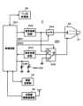
位置検出センサ21及び表示デバイス22は、情報処理装置の処理回路200に接続されている。処理回路200は、情報処理装置2の全体を制御する制御回路201に対して、導体選択回路202と、切替スイッチ回路203と、位置検出回路204と、送信情報処理回路205と、表示制御回路206と、記憶部207と、近距離無線通信部208と、通信部209とが接続されて構成されている。The
導体選択回路202には、位置検出センサ21の第1の導体群212及び第2の導体群213の複数の導体のそれぞれが接続されており、導体選択回路202は、制御回路201からの制御信号により、それら第1の導体群212及び第2の導体群213の複数の導体の内の1個または複数個の導体が選択される。Each of the multiple conductors of the
導体選択回路202は、切替スイッチ回路203に接続されている。切替スイッチ回路203は、制御回路201からの切替制御信号により、位置検出センサ21からの信号を受信するとき(受信モード)と、位置検出センサ21から情報を送信するとき(送信モード)とで切り替えられる。The
すなわち、切替スイッチ回路203は、位置検出センサ21で、後述するように、電子ペン3からの信号を受信する受信モードのときには、制御回路201からの切替制御信号により、端子R側に切り替えられて、導体選択回路202で選択された導体を、位置検出回路204の入力端に接続するように切り替える。また、位置検出センサ21から情報を送信する送信モードのときには、制御回路201からの切替制御信号により、端子T側に切り替えられて、導体選択回路202で選択された導体を、送信情報処理回路205の出力端に接続するように切り替える。この実施形態では、情報処理装置2の制御回路201は、後述するように、電子ペン3とタイミングの同期をとり、送信モードと受信モードとを時分割で実行するように構成されている。That is, in a reception mode in which the
位置検出回路204は、導体選択回路202で選択された導体からの受信信号の信号レベルを検出し、その検出結果から、電子ペン3により指示された位置を検出する。そして、位置検出回路204は、その検出した位置の情報を制御回路201に供給する。制御回路201は、受け取った電子ペンの指示位置の情報に基づいて、後述するような処理を実行する。The
この実施形態では、位置検出回路204は、導体選択回路202で選択された導体からの受信信号から、電子ペン3から送られてくる筆圧情報やペン識別情報(以下ペンIDという)を検出し、その検出した筆圧情報やペンIDを制御回路201に供給する処理も行う。さらに、位置検出回路204は、導体選択回路202で選択された導体からの受信信号から、電子ペン3の傾きを検出する処理も行い、検出した傾きの情報を制御回路201に供給する処理も行う。In this embodiment, the
送信情報処理回路205は、制御回路201からの送信情報を、位置検出センサ21を通じて電子ペン3に送信するのに適した信号に変換(変調)し、その変換(変調)した信号を切替スイッチ回路203を通じて導体選択回路202で選択されている導体に供給して、電子ペン3に対して送出するようにする。The transmission
表示制御回路206は、表示デバイス22に接続されており、制御回路201からの表示画像情報を受けて、その表示画像情報に応じた表示画像を、表示デバイス22の表示画面に表示するように制御する。The
記憶部207は、制御回路201による制御に基づき、情報の記憶及び読み出しが行われる。この実施形態では、位置検出センサ21の表示デバイス22の表示領域に対応する検出領域には、複数の部分検出エリアが予め設定されている。すなわち、図1の例では、位置検出センサ21の検出領域内に、矩形の3個の部分検出エリアAR1,AR2,AR3が設定されている。そして、これら3個の部分検出エリアAR1,AR2,AR3以外のエリアAR0は、この実施形態では、電子ペン3による筆記入力検出エリアとされている。図1及び図2に示すように、表示デバイス22の表示画面には、部分検出エリアAR1,AR2,AR3を使用者に視覚的に認識させるためのエリア枠画像AR1p,AR2p,AR3pが表示されている。 The
この実施形態では、制御回路201は、電子ペン3による指示位置が、位置検出センサ21の検出領域内のいずれのエリア内の位置であるかにより異なる、それぞれのエリアに対応して予め設定された機能処理を実行することができるように構成されている。そして、記憶部207は、筆記入力検出エリアAR0及び部分検出エリアAR1,AR2,AR3のそれぞれに対応付けられた記憶領域を備えている。In this embodiment, the
制御回路201は、電子ペン3による指示位置が、位置検出センサ21の検出領域内のいずれのエリア内の位置であるかに応じた処理制御を行うと共に、記憶部207の、エリアに対応する記憶領域に対する書き込みあるいは読み出しの処理制御を行う。制御回路201には、その処理制御プログラムがインストールされている。The
位置検出センサ21の検出領域内の筆記入力検出エリアAR0及び部分検出エリアAR1,AR2,AR3に対応して設定されている機能処理の例については、後で、詳述する。なお、部分検出エリアは、この例のような3個の部分検出エリアAR1,AR2,AR3に限定される訳ではなく、1個でも、2個でも、また、4個以上であってもよい。そして、各部分エリアの大きさ及び形状も任意であり、例えば電子ペン3により、位置検出センサ21上において、その位置、大きさ及び形状を指定することができる。さらに、各部分検出エリアに設定する機能も、例えば情報処理装置2が、設定可能な機能のメニューの一覧を表示デバイス22の表示画面に表示し、その一覧から電子ペン3により選択指示することで設定することができる。An example of the function processing set corresponding to the handwriting input detection area AR0 and the partial detection areas AR1, AR2, and AR3 in the detection area of the
近距離無線通信部208は、後述するように、電子ペン3に設けられている近距離無線通信部との間で無線通信をするためのもので、この実施形態では、ブルートゥース(登録商標)規格の無線通信部の構成とされている。制御回路201は、この近距離無線通信部208を通じて取得した情報を記憶部207に記憶したり、その取得した情報に応じた画像を、表示制御回路206に供給し、表示デバイス22の表示画面に表示したりする処理を行うことができるように構成されている。As described below, the short-range
通信部209は、この実施形態では、通信回線を通じてインターネットに接続したり、特定の相手との通信(メールなど)を行うためのものである。制御回路201は、この通信部209を通じて取得した情報を記憶部207に記憶したり、その取得した情報に応じた画像を、表示制御回路206に供給し、表示デバイス22の表示画面に表示したりする処理を行うことができるように構成されている。In this embodiment, the
[電子ペン3の構成例]
この実施形態の電子ペン3は、情報処理装置2の静電容量方式の位置検出センサ21とインタクラクションする静電容量方式の構成とされている。この例の電子ペン3は、図1に示すように、ペン型の筒状の筐体30を備え、この筐体30の軸心方向の一端側をペン先側として、このペン先側に、第1の電極を構成する芯体(中心電極)31と、第2の電極を構成する周辺電極32とが設けられている。周辺電極32は、芯体31とは絶縁された状態で、当該芯体31の周囲を囲むように配設されており、図のように、芯体31の先端側になるほど先細となるようなテーパー形状を備えている。 [Configuration example of electronic pen 3]
The
そして、筐体30の中空部内には、図1において、それぞれ点線で示すように、芯体31の先端に印可される圧力(筆圧)を検出する筆圧検出部33と、情報記憶部34と、近距離無線通信部35と、ペンID記憶部36とが設けられると共に、図示を省略するプリント基板上に配される電子ペン回路300が設けられる。筆圧検出部33は、例えば印可される筆圧を静電容量の変化として検出する、周知の可変容量コンデンサの構成とされている。1, a pen
図3は、この実施形態の電子ペン3の電子ペン回路300の構成例を、当該電子ペン回路300と、筆圧検出部33、情報記憶部34、近距離無線通信部35及びペンID記憶部36との接続関係を含めて説明するための回路図である。Figure 3 is a circuit diagram for explaining an example configuration of the
この例では、図3に示すように、電子ペン回路300はプリント基板に載置されているIC(Integrated Circuit)により構成される制御回路301を備える。そして、この制御回路301に対して、信号発信回路302と信号受信回路303とが接続されると共に、筆圧検出部33で構成される可変容量コンデンサ33Cが接続されている。可変容量コンデンサ33Cには、並列に抵抗33Rが接続されている。また、制御回路301に対して、情報記憶部34、近距離無線通信部35及びペンID記憶部36が接続されている。In this example, as shown in Figure 3, the
信号発信回路302の信号出力端は、スイッチ回路304を通じて、芯体31に接続されている。また、この例では、信号発信回路302の信号出力端は、切替スイッチ回路305の端子Sに接続されている。この切替スイッチ回路305の可動端子Mは、周辺電極32に接続されている。切替スイッチ回路305の端子Rは、信号受信回路303の入力端に接続されている。また、切替スイッチ回路305の端子Gは、アース電極(グランド電極)に接続されている。The signal output terminal of the
そして、制御回路301は、スイッチ回路304に対して、当該スイッチ回路304をオンオフ制御する制御信号SW1を供給する。また、制御回路301は、切替スイッチ回路305に対して、可動端子Mを、端子S、端子R、端子Gのいずれに接続するかを切り替える切替制御信号SW2を供給する。The
信号受信回路303は、切替スイッチ回路305が端子Rに切り替えられているときに、周辺電極32を通じて位置検出センサ21からの信号を受信したか否かを監視する。信号受信回路303は、周辺電極32を通じた位置検出センサ21からの信号の受信を検出していないときには、その旨の検出結果を制御回路301に供給する。そして、信号受信回路303は、周辺電極32を通じた位置検出センサ21からの信号の受信を検出したときには、受信した信号に応じた復調等の処理をして、その処理結果の信号を制御回路301に送る。When the
信号発信回路302は、芯体31から送出する信号として、情報処理装置2の位置検出回路204で位置検出のための所定周波数の位置検出用信号(バースト信号)と、付加情報としての筆圧検出部33で検出した筆圧に応じた筆圧情報及びペンIDとを含む信号を出力する。また、信号発信回路302は、周辺電極32から送出する信号として、電子ペン3の傾き角の検出用の信号を出力する。電子ペン3の傾き角は、位置検出センサ21 の検出面に対する電子ペン3の軸心方向の角度である。The
信号発信回路302は、制御回路301による制御の下に、芯体31から送出する信号、また、周辺電極32から送出する信号を生成して送出する。この場合に、制御回路301は、芯体31から送出する信号として、信号発信回路302から位置検出用のバースト信号を送出している期間に、可変容量コンデンサ33Cを充放電させ、放電開始時点から、可変容量コンデンサ33Cの両端電圧が予め定められている所定の電圧になるまでの時間を計測することで、可変容量コンデンサ33Cのその時の静電容量を検出し、その検出した静電容量に基づき筆圧を検出する。Under the control of the
そして、制御回路301は、検出した筆圧を、この例では複数ビットのデジタル信号に変換し、このデジタル信号に応じた筆圧情報を、位置検出用のバースト信号に引き続いて信号発信回路302から出力するように、この信号発信回路302を制御する。また、制御回路301は、ペンID記憶部36から読み出したペンIDを、この例では複数ビットのデジタル信号に変換し、筆圧情報に引き続いて信号発信回路302から出力するように、この信号発信回路302を制御する。The
情報記憶部34は、制御回路301による制御に基づき、情報処理装置2から位置検出センサ21及び周辺電極32を通じて受信した情報を記憶する。この情報記憶部34に記憶された情報は、制御回路301の制御に基づき読み出されて近距離無線通信部35から外部に送出されるようにされる。この例では、制御回路301は、情報記憶部34に記憶されている情報が近距離無線通信部35を通じて送信されたときには、送信完了を確認した後、情報記憶部34に記憶されている情報を消去するようにする。The
なお、情報記憶部34に記憶されている情報を送信後に自動的に消去するのではなく、電子ペン3に、例えばサイドスイッチなどの操作手段を設けて、当該操作手段が長押し操作されるなどの特定の操作を消去指示操作とし、その消去指示操作に基づいて、情報記憶部34に記憶されている情報を消去するように構成してもよい。In addition, instead of automatically erasing the information stored in the
近距離無線通信部35は、送出用部の例であり、情報処理装置2の近距離無線通信部208と無線通信するために、この例では前述したように、ブルートゥース(登録商標)規格の無線通信手段が用いられている。なお、この近距離無線通信部35は、情報処理装置2に限らず、ブルートゥース(登録商標)規格の無線通信手段が用いられているパーソナルコンピュータなどとも無線通信が可能であることは言うまでない。The short-range
図1及び図3では図示は省略したが、電子ペン3の筐体30の中空部内には、1次電池あるいは2次電池からなる電源部が設けられており、この電源部からの電源電圧が制御回路301の制御により各部に供給されている。Although not shown in Figures 1 and 3, a power supply unit consisting of a primary or secondary battery is provided within the hollow portion of the
この実施形態の電子ペン3の電子ペン回路300における動作を、図4を参照しながら説明する。The operation of the
この実施形態の電子ペン回路300では、制御回路301は、電子ペンと位置検出センサ21とが静電結合する状態となっていないときには、切替スイッチ回路305は、切替制御信号SW2(図4(E)参照)により、端子Rに切り替えて、周辺電極32を切替スイッチ回路305を通じて信号受信回路303に接続する。そして、制御回路301は、信号受信回路303からの位置検出センサ21からの信号の受信を監視出力(図4(A)参照)に基づいて、位置検出センサ21からの信号の受信を監視する。このとき、制御回路301は、切替制御信号SW1(図4(D)参照)によりスイッチ回路304はオフとしておくようにする。In the
なお、この実施形態では、制御回路301及び信号受信回路303は、位置検出センサから受信する信号の監視を常時実行するのではなく、図4(B)の前半に示すように、所定の周期で繰り返す間欠的な信号受信監視期間においてのみ実行するようにする。In this embodiment, the
制御回路301は、信号受信回路303からの監視出力から、位置検出センサ21からの信号の受信を検出したときには、電子ペン回路300を、スタンバイ状態からアクティブ状態に切り替え、電源部からの電源電圧を各部に供給するように制御する。そして、制御回路301は、図4(B)に示すように、電子ペン回路300の動作モードを、信号受信モードと信号送出モードとに時分割で切り替えるように制御する。この場合に、時分割制御は、信号受信モードから開始するようにされている。When the
信号受信モードにおいては、制御回路301は、切替制御信号SW2により、図4(E)に示すように、切替スイッチ回路305を固定端子R側に切り替える。したがって、信号受信回路303は、周辺電極32で受信した位置検出センサからの信号を切替スイッチ回路304を通じて受け取り、当該受信した信号に応じた復調等の処理をして、その処理結果の信号を制御回路301に送る。そして、この信号受信モードでは、制御回路301は、図4(D)に示すように、切替制御信号SW1によりスイッチ回路304をオフとして、中心電極としての芯体31からの信号送出は行わないようにする。 In the signal reception mode, the
制御回路301は、信号受信回路303からの信号により、位置検出センサから受信した信号を解析して、相手の位置検出装置の仕様を判断し、その判断結果に基づいて、相手の位置検出装置の位置検出センサと信号のインタラクションをするタイミングを定める。そして、制御回路301は、信号発信回路302から出力する信号のフォーマットを、相手の情報処理装置2の仕様に合致するものとなるように制御し、定めたタイミングで位置検出センサとのインタラクションを行うようにする。 The
また、この信号受信モードにおいては、制御回路301は、信号受信回路303から、位置検出センサ21を介して周辺電極32経由で送られてくる情報処理装置2からの情報を受け取ったときには、受け取った情報を情報記憶部34に記憶する処理も行う。In addition, in this signal reception mode, when the
そして、制御回路301は、信号送出モードにおいては、この実施形態では、位置検出用のバースト信号と筆圧情報とペンIDとを情報処理装置2側に送出する位置検出期間Taと、電子ペン3の傾き角の検出用の傾き検出期間Tbとを時分割で、複数回、実行するようにする。 In this embodiment, in the signal sending mode, the
制御回路301は、位置検出期間Taにおいては、制御信号SW1(図4(D)参照)により、スイッチ回路304はオンとし、また、切替スイッチ回路305は、切替制御信号SW2(図4(E)参照)により可動端子Mを固定端子Gに接続する。したがって、周辺電極32は、アース端子に接続される。During the position detection period Ta, the
そして、制御回路301は、位置検出期間Taにおいては、信号発信回路302を制御して、情報処理装置2での位置検出のための所定周波数の位置検出用信号(バースト信号)と、筆圧検出部33で検出した筆圧に応じた筆圧情報と、ペンIDとを含む信号を、スイッチ回路304を通じて芯体31に供給して、静電容量結合により位置検出センサに送信するようにする。このとき、周辺電極32は、アース端子に接続されているので、中心電極としての芯体31に対してシールド電極として働き、芯体31へのノイズの混入を防止する。 During the position detection period Ta, the
傾き検出期間Tbにおいては、制御回路301は、制御信号SW1(図4(D)参照)により、スイッチ回路304はオフとし、また、切替スイッチ回路305は、切替制御信号SW2(図4(E)参照)により可動端子Mは固定端子Sに接続するように制御する。そして、この傾き検出期間Tbにおいては、制御回路301は、信号発信回路302から、電子ペン3の傾き角の検出用のバースト信号を発生させて、周辺電極32から送出させるように制御する。During the tilt detection period Tb, the
なお、情報処理装置2の位置検出回路204では、この周辺電極32からの信号の位置検出センサ21における検出位置の分布を検出し、その検出結果から電子ペン3の傾きを検出するようにする。In addition, the
[部分検出エリアAR1,AR2,AR3に対応する機能処理の例]
部分検出エリアAR1,AR2,AR3に対応して設定されている機能処理を説明する前に、電子ペン3の指示位置が、筆記入力検出エリアAR0内であるときの情報処理装置2の処理動作について説明する。 [Example of functional processing corresponding to partial detection areas AR1, AR2, and AR3]
Before describing the functional processes set corresponding to the partial detection areas AR1, AR2, and AR3, a processing operation of the
すなわち、この実施形態では、電子ペン3の指示位置が、筆記入力検出エリアAR0内であると、位置検出回路204で検出されたときには、情報処理装置2の制御回路201は、検出された指示位置の情報を、筆記入力情報として、記憶部207の筆記入力検出エリアAR0に対応する記憶領域に記憶するようにする。このとき、この実施形態では、電子ペン3から送られてくる筆圧情報やペンIDも、筆記入力情報として併せて記憶する。そして、制御回路201は、検出された指示位置の情報に基づく筆記跡の画像情報を生成して、表示制御回路206に供給する。表示制御回路206は、その筆記跡の画像Psを、図1及び図2に示すように、表示デバイス22の表示画面に表示する。そして、筆圧情報は、その筆記跡の線の太さなどに反映されて表示される。That is, in this embodiment, when the
次に、この実施形態において、情報処理装置2の位置検出センサ21の検出領域内において、部分検出エリアAR1,AR2,AR3に対応して設定されている機能処理の例について説明する。Next, in this embodiment, we will explain an example of functional processing that is set corresponding to partial detection areas AR1, AR2, and AR3 within the detection area of the
この例では、部分検出エリアAR1に対しては、それまでに筆記入力検出エリアAR0で検出された筆記入力情報を、記憶部207から読み出して、電子ペン3に送信する機能が設定されている。すなわち、この例では、電子ペン3の指示位置が、部分検出エリアAR1内であると位置検出回路204で検出されたときには、制御回路201は、それまでに筆記入力検出エリアAR0で検出された筆記入力情報を、記憶部207から読み出して、送信情報処理回路205に供給するようにする。In this example, for partial detection area AR1, a function is set to read handwriting input information detected up to that point in handwriting input detection area AR0 from
この場合に、この例では、筆記入力情報は、記憶部207の筆記入力検出エリアAR0に対応する記憶領域から読み出すように構成されている。したがって、この例では、記憶部207には、部分検出エリアAR1に対応する記憶領域を別個に設定する必要はなく、筆記入力検出エリアAR0に対応する記憶領域が、部分検出エリアAR1に対応する記憶領域も兼ねる。なお、記憶部207に、部分検出エリアAR1に対応する記憶領域を設定して、筆記入力情報を、この設定した記憶領域にも記憶しておき、当該記憶エリアから筆記入力情報を読み出すようにしてもよい。In this case, in this example, the handwritten input information is configured to be read from a memory area corresponding to the handwritten input detection area AR0 of the
そして、制御回路201は、切替スイッチ回路203を端子T側に切り替えると共に、導体選択回路202を、部分検出エリアAR1において、交点を有する第1の導体212Y及び第2の導体213Xを選択するように制御する。これにより、記憶部207に記憶されていた筆記入力情報が、位置検出センサ21の部分検出エリアAR1に位置している電子ペン3に対して送信される。電子ペン3では、周辺電極32で、位置検出センサ21を通じて送信されてくる筆記入力情報を受信して、記憶部34に記憶する。Then, the
この部分検出エリアAR1に対して設定された機能を用いることで、情報処理装置2において電子ペン3により筆記入力した情報を、別の情報処理装置に引き継いて、筆記入力を継続して行うことができる。By using the function set for this partial detection area AR1, information handwritten and input using the
すなわち、図5(A)の左側に示すように、使用者が、情報処理装置2の位置検出センサ21上の筆記入力検出エリアAR0において、電子ペン3により、例えば筆記跡Psを形成する筆記入力を行った後、電子ペン3の芯体31による指示位置を部分検出エリアAR1に移すと、情報処理装置2は、位置検出センサ21の部分検出エリアAR1から、それまでの筆記入力情報を電子ペン3の周辺電極32に送信してくるので、電子ペン3は、周辺電極32を通じてその筆記入力情報を受信して、記憶部34に記憶する。That is, as shown on the left side of Figure 5 (A), when a user performs handwriting input, for example forming a handwriting trace Ps, with the
次に、使用者は、以上のようにして、筆記入力情報を記憶部34に記憶した電子ペン3を、図5(A)の右側に示すように、近距離無線通信部35と通信可能な通信部を備える他の情報処理装置2´の近傍に持ち越し、電子ペン3と当該情報処理装置2´とで近距離無線通信を行わせるようにする。すると、電子ペン3は、記憶部34に記憶されている筆記入力情報を読み出して情報処理装置2´に送信する。したがって、情報処理装置2´では、電子ペン3から受信した筆記入力情報に基づき、筆記跡Psをその表示デバイス22´の表示画面に表示することができ、使用者は、情報処理装置2´の位置検出センサ21´に対して、筆記跡Psに引き続いた筆記入力をすることができるようになる。Next, the user brings the
なお、電子ペン3は、記憶部34に記憶されている筆記入力情報を、近距離無線通信部35を通じてではなく、図5の右側において点線で示すように、芯体31又は周辺電極32から、位置検出センサ21´を通じて情報処理装置2´に送信するようにしてもよい。In addition, the
この場合に、情報処理装置2´は、位置検出センサ21´と電子ペン3との電界結合を検出したときに、電子ペン3に対して、記憶部34の記憶情報の取得要求を送り、その取得要求に応じて電子ペン3から位置検出センサ21´を通じて送られてくる情報を受け取るようにする。そして、電子ペン3は、情報処理装置2´から記憶部34の記憶情報の取得要求を受け取ったときには、記憶部34に転送する記憶情報が存在するか否かを判別し、転送する記憶情報が存在する場合には、その記憶情報を記憶部34から読み出して位置検出センサ21´を通じて送り、記憶情報が存在しないときには、その旨を位置検出センサ21´を通じて送るようにする。In this case, when the information processing device 2' detects electric field coupling between the position detection sensor 21' and the
また、電子ペン3は、情報処理装置2´からの取得要求を受けたときではなく、情報処理装置2´の位置検出センサ21´との電界結合を検出したときに、記憶部34の記憶情報を位置検出センサ21´を通じて情報処理装置2´に送るように構成してもよい。In addition, the
次に、この例では、部分検出エリアAR2に対しては、ペンIDに対応付けられて記憶されている情報を、記憶部207から読み出して、電子ペン3に送信する機能が設定されている。使用者毎に異なる電子ペン3を使用することを想定した場合には、ペンIDは、使用者識別情報と同等となる。そこで、この例では、それぞれの使用者に伝達したい情報を、記憶部207の部分検出エリアAR2に対応する記憶領域に、それぞれの使用者が使用する電子ペン3のペンIDに対応付けて予め記憶しておく。それぞれの使用者に伝達したい情報としては、電子ペン3が用いられてペンIDに対応して情報処理装置2で管理されている相手を指定して入力された情報のほか、通信部209を通じて取得された情報であってもよい。この場合に、通信部209を通じて取得された情報には、電子メールの受信情報であって、ペンIDに対応して情報処理装置2で管理されている受信者宛の受信情報を含むものである。Next, in this example, the partial detection area AR2 is set to have a function of reading out information stored in association with the pen ID from the
この部分検出エリアAR2に対して設定された機能を用いることで、情報処理装置2から、特定の電子ペン3の使用者に、当該使用者に対応付けて予め用意した情報を転送することができる。電子ペン3の使用者は、別の情報処理装置2´で、その転送された情報を表示して知得することができる。By using the function set for this partial detection area AR2, it is possible to transfer information prepared in advance in association with a specific user from the
すなわち、図5(B)の左側に示すように、使用者が、情報処理装置2の位置検出センサ21上において、電子ペン3の芯体31による指示位置を部分検出エリアAR2に移すと、情報処理装置2は、位置検出センサ21の部分検出エリアAR2から、当該電子ペン3のペンIDに対応する情報を電子ペン3の周辺電極32に送信してくるので、電子ペン3は、周辺電極32を通じてそのペンIDに対応する情報を受信して、記憶部34に記憶する。That is, as shown on the left side of Figure 5 (B), when the user moves the pointing position indicated by the
次に、使用者は、ペンIDに対応する情報を記憶部34に記憶した電子ペン3を、図5(B)の右側に示すように、近距離無線通信部35と通信可能な通信部を備える他の情報処理装置2´の近傍に持ち越し、電子ペン3と当該情報処理装置2´とで近距離無線通信を行わせるようにする。すると、電子ペン3は、記憶部34に記憶されている情報を読み出して情報処理装置2´に送信する。したがって、情報処理装置2´では、電子ペン3から受信した情報に基づき、ペンIDに対応する情報をその表示デバイス22´の表示画面に表示することができる。したがって、使用者は、情報処理装置2´において、使用者宛に用意された情報を、他の情報処理装置2´で知得することができるようになる。Next, the user brings the
なお、図5(B)の例では、図示は省略したが、この例の場合にも、情報処理装置2´が位置検出センサ21´を備えるものである場合には、電子ペン3は、記憶部34に記憶されているペンIDに対応する情報を、近距離無線通信部35を通じてではなく、芯体31又は周辺電極32から、位置検出センサ21´を通じて情報処理装置2´に送信するようにしてもよい。Although not shown in the example of Figure 5 (B), even in this example, if the information processing device 2' is equipped with a position detection sensor 21', the
次に、この例では、部分検出エリアAR3に対しては、所定のキーワードに対応付けられて記憶されている情報を、記憶部207から読み出して、電子ペン3に送信する機能が設定されている。この例では、所定の1又は複数のキーワードと、そのそれぞれのキーワードに対応する情報との対応情報を、記憶部207の部分検出エリアAR3に対応する記憶領域に、予め記憶しておく。この場合に、キーワードに対応して記憶する情報としては、電子ペン3が用いられて入力された情報であってもよいし、通信部209を通じて取得された情報であってもよい。Next, in this example, a function is set for the partial detection area AR3 to read information stored in association with a predetermined keyword from the
この部分検出エリアAR3に対して設定された機能を用いることで、情報処理装置2から、キーワードに対応する情報を電子ペン3に転送することができる。電子ペン3の使用者は、別の情報処理装置2´で、その転送された情報を表示して知得することができる。By using the function set for this partial detection area AR3, information corresponding to the keyword can be transferred from the
すなわち、図5(C)の左側に示すように、使用者が、情報処理装置2の位置検出センサ21上において、電子ペン3の芯体31による指示位置を部分検出エリアAR3に移すと、情報処理装置2は、この例では、筆記入力検出エリアAR0に対応する表示エリアに、キーワードの選択入力を促すメッセージを表示すると共に、図示は省略するが、部分検出エリアAR3に対応する表示エリアに、記憶部207に記憶されているキーワードの一覧を表示する。That is, as shown on the left side of Figure 5 (C), when the user moves the position indicated by the
このキーワードの一覧から、電子ペン3によりキーワードが選択されると、情報処理装置2は、位置検出センサ21の部分検出エリアAR3から、当該キーワードに対応する情報を電子ペン3の周辺電極32に送信する。電子ペン3は、周辺電極32を通じて、この選択したキーワードに対応する情報を受信して、記憶部34に記憶する。なお、電子ペン3により、複数のキーワードを選択することで、情報処理装置2が、当該選択された複数のキーワードに対応する情報を電子ペン3に送信し、電子ペン3が、それを記憶部34に記憶するようにすることもできる。When a keyword is selected from this list of keywords by the
次に、使用者は、キーワードに対応する情報を記憶部34に記憶した電子ペン3を、図5(C)の右側に示すように、近距離無線通信部35と通信可能な通信部を備える他の情報処理装置2´の近傍に持ち越し、電子ペン3と当該情報処理装置2´とで近距離無線通信を行わせるようにする。すると、電子ペン3は、記憶部34に記憶されている情報を読み出して情報処理装置2´に送信する。したがって、情報処理装置2´では、電子ペン3から受信した情報に基づき、キーワードに対応する情報をその表示デバイス22´の表示画面に表示することができる。したがって、使用者は、情報処理装置2´において用意されたキーワードに対応する情報を、他の情報処理装置2´で知得することができるようになる。Next, the user brings the
なお、図示は省略したが、図5(C)の例の場合にも、情報処理装置2´が位置検出センサ21´を備えるものである場合には、電子ペン3は、記憶部34に記憶されているキーワードに対応する情報を、近距離無線通信部35を通じてではなく、芯体31又は周辺電極32から、位置検出センサ21´を通じて情報処理装置2´に送信するようにしてもよい。Although not shown in the figure, in the example of Figure 5 (C), if the information processing device 2' is equipped with a position detection sensor 21', the
なお、電子ペン3により、部分検出エリアAR1~AR3のいずれか一つではなく、複数個、あるいは全てを位置指示することで、情報記憶部34には、その位置指示した部分検出エリアのそれぞれに対応した情報の全てを記憶可能である。In addition, by using the
なお、情報処理装置2´は、情報処理装置2と同様の構成を備えるものでなくともよいことは言うまでない。ただし、筆記入力情報を転送する情報処理装置2´としては、位置検出センサ21´を備えるものである方が良いことは言うまでもない。また、図5(B)の例のペンIDに対応する情報や、図5(C)の例のキーワードに対応する情報が転送される情報処理装置2´としては、位置検出センサ21´は備える必要はなく、少なくとも、それらの情報を表示するための表示画面を備える表示デバイス22´を備えるものであればよい。 It goes without saying that the information processing device 2' does not have to have the same configuration as the
[電子ペン3及び情報処理装置2における動作の説明]
次に、以上のような機能を実現するための電子ペン3及び情報処理装置2での処理動作の流れについて説明する。 [Description of the Operation of the
Next, the flow of processing operations in the
<電子ペン3の動作例の説明>
図6~図8は、電子ペン3の電子ペン回路300において、以上説明した機能処理を含む動作を実現するための処理の流れの例を説明するためのフローチャートを示す図である。このフローチャートの各ステップの動作は、電子ペン回路300の制御回路301が行うものである。 <Explanation of Operation Example of
6 to 8 are diagrams showing flowcharts illustrating an example of a process flow for realizing operations including the above-described functional processes in the
すなわち、制御回路301は、情報処理装置2の位置検出センサ21と電界結合する状態になっているか否かを判別する(ステップS1)。電子ペン3が、情報処理装置2の位置検出センサ21と電界結合する状態になっている状態は、互いに信号をインタラクションすることができる状体であり、電子ペン3の芯体31が位置検出センサの検出面に接触している状態のみならず、検出面かが若干離間して近接しているホバー状態を含む。That is, the
このステップS1で、情報処理装置2の位置検出センサ21と電界結合する状態になっていると判別したときには、制御回路301は、信号受信モードの期間であるか否か判別する(ステップS2)。このステップS2で、信号受信モードの期間ではないと判別したときには、制御回路301は、信号送出モードの期間であるか否か判別する(ステップS4)。そして、このステップS4で、信号送出モードの期間ではないと判別したときには、制御回路301は、処理をステップS1に戻し、このステップS1からの処理を繰り返す。 If it is determined in step S1 that the
そして、ステップS4で、信号送出モードの期間であると判別したときには、制御回路301は、位置検出期間Taか、傾き検出期間Tbのいずれであるかを判別する(図7のステップS11)。このステップS11で、位置検出期間Taであると判別したときには、制御回路301は、スイッチ回路304はオン、切替スイッチ回路305は端子Gに接続するように切り替え制御する(ステップS12)。次いで、制御回路301は、信号発信回路302から、位置検出用信号と、筆圧情報と、ペンIDとを中心電極としての芯体31から送出させるように制御する(ステップS13)。このステップS13の次には、制御回路301は、処理をステップS1に戻し、このステップS1からの処理を繰り返す。 Then, when it is determined in stepS4 that the period is the signal transmission mode period, the
ステップS11で、傾き検出期間Tbであると判別したときには、制御回路301は、スイッチ回路304はオフ、切替スイッチ回路305は端子Sに接続するように切り替え制御する(ステップS14)。次いで、制御回路301は、信号発信回路302から、傾き検出用信号を周辺電極32から送出させるように制御する(ステップS15)。このステップS15の次には、制御回路301は、処理をステップS1に戻し、このステップS1からの処理を繰り返す。When it is determined in step S11 that it is the tilt detection period Tb, the
図6のステップS2で、信号受信モードの期間であると判別したときには、制御回路301は、スイッチ回路304はオフ、切替スイッチ回路305は端子Rに接続するように切り替え制御する(ステップS3)。次いで、制御回路301は、信号受信回路303の出力に基づいて、受信信号を検出したか否か判別する(ステップS5)。このステップS5で、受信信号を検出してはいないと判別したときには、制御回路301は、処理をステップS1に戻し、このステップS1からの処理を繰り返す。 6, when it is determined that the period is the signal reception mode period, the
そして、ステップS5で、受信信号を検出したと判別したときには、制御回路301は、位置検出センサ21及び周辺電極32を通じた信号を受信して処理する(ステップS6)。そして、制御回路301は、このステップS6での処理により、受信信号は、転送が必要な情報であるか否かを判別する(ステップS7)。転送が必要な情報であるか否かは、受信信号が、情報処理装置2の仕様に応じた信号及びタイミング制御信号であるか否かにより判断し、受信信号が、情報処理装置2の仕様に応じた信号及びタイミング制御信号ではないと判別したときには、転送が必要な情報であると判別する。なお、情報処理装置2からの情報に、転送が必要な情報であるか否かを示す情報が含まれていて、その情報に基づいて、電子ペン3が転送が必要な情報であるか否かを判別するようにしてもよい。Then, when it is determined in step S5 that a received signal has been detected, the
そして、このステップS7で、受信信号は、転送が必要な情報ではなく、情報処理装置2の仕様に応じた信号及びタイミング制御信号であると判別したときには、制御回路301は、その受信信号に応じて、電子ペン3における仕様を情報処理装置2に対応されるように制御すると共に、時分割処理のタイミングを制御するなど、受信信号に応じた処理を行う(ステップS8)。Then, in step S7, when it is determined that the received signal is not information that requires transfer, but is a signal and a timing control signal according to the specifications of the
また、このステップS7で、受信信号は、転送が必要な情報であると判別したときには、制御回路301は、受信した情報処理装置2からの情報を、記憶部34に格納する処理を行う(ステップS9)。このステップS9の次には、制御回路301は、処理をステップS1に戻し、このステップS1からの処理を繰り返す。Also, in step S7, when it is determined that the received signal is information that requires transfer, the
そして、ステップS1で、情報処理装置2の位置検出センサ21と電界結合する状態になってはいないと判別したときには、制御回路301は、他の装置と近距離無線通信のペアリング状態になったか否か判別する(図8のステップS21)。このステップS21で、他の装置と近距離無線通信のペアリング状態にはなっていないと判別したときには、制御回路301は、処理をステップS1に戻し、このステップS1からの処理を繰り返す。If it is determined in step S1 that the
ステップS21で、他の装置と近距離無線通信のペアリング状態になったと判別したときには、制御回路301は、情報記憶部34に記憶されている情報を読み出して、ペアリング状態の他の装置に送信する(ステップS22)。送信が終了後、制御回路301は、処理をステップS1に戻し、このステップS1からの処理を繰り返す。When it is determined in step S21 that the device is in a paired state for short-range wireless communication with another device, the
<情報処理装置2の動作例の説明>
図9及び図10は、情報処理装置2の処理回路200において、以上説明した機能処理を含む動作を実現するための処理の流れの例を説明するためのフローチャートを示す図である。このフローチャートの各ステップの動作は、処理回路200の制御回路201が行うものである。 <Explanation of an operation example of the
9 and 10 are diagrams showing flowcharts for explaining an example of a process flow for realizing operations including the functional processes described above in the
制御回路201は、電子ペン3と静電容量結合するための信号(タイミング信号や仕様を示す信号を含む)を送出する(ステップS31)。この信号の送出に対して静電容量結合した電子ペンからは位置検出用信号などの信号が送られてくるので、制御回路201は、電子ペン3からの信号を受信したか否か判別し(ステップS32)、電子ペン3からの信号を受信してはいないと判別したときには、処理をステップS31に戻し、このステップS31以降の処理を繰り返す。The
ステップS32で、電子ペン3からの信号を受信したと判別したときには、制御回路201は、受信信号の処理、すなわち、位置検出センサ21上での電子ペン3による指示位置の検出、電子ペン3の傾きの検出、筆圧情報及びペンIDの取得を行う(ステップS33)。When it is determined in step S32 that a signal has been received from the
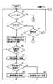
次に、制御回路201は、検出した電子ペン3による指示位置が筆記入力検出エリアAR0内であるか否か判別する(ステップS34)。このステップS34で、検出した電子ペン3による指示位置が筆記入力検出エリアAR0内であると判別したときには、制御回路201は、検出した指示位置、電子ペン3の傾き角、及び取得した筆圧情報及びペンIDを記憶部207に記憶する(ステップS35)。制御回路201は、このステップS35の次には、処理をステップS32に戻し、このステップS32以降の処理を繰り返す。Next, the
ステップS34で、検出した電子ペン3による指示位置が筆記入力検出エリアAR0内ではないと判別したときには、制御回路201は、検出した電子ペン3による指示位置が部分検出エリアAR1内であるか否か判別する(ステップS36)。このステップS36で、検出した電子ペン3による指示位置が部分検出エリアAR1内であると判別したときには、制御回路201は、それまでに記憶されている電子ペン3による指示位置、電子ペン3の傾き角、筆圧情報及びペンIDを記憶部207から読み出し、位置検出センサ21の部分検出エリアAR1から送出する(ステップS37)。制御回路201は、このステップS37の次には、処理をステップS32に戻し、このステップS32以降の処理を繰り返す。When it is determined in step S34 that the position pointed to by the detected
ステップS36で、検出した電子ペン3による指示位置が部分検出エリアAR1内ではないと判別したときには、制御回路201は、検出した電子ペン3による指示位置が部分検出エリアAR2内であるか否か判別する(図10のステップS41)。このステップS41で、検出した電子ペン3による指示位置が部分検出エリアAR2内であると判別したときには、制御回路201は、記憶部207に、ステップS33で取得したペンIDに対応する情報が記憶されているか否か判別する(ステップS42)。If it is determined in step S36 that the position pointed to by the detected
このステップS42で、記憶部207に、ステップS33で取得したペンIDに対応する情報が記憶されていると判別したときには、制御回路201は、記憶部207から当該ペンIDに対応する情報を読み出して、位置検出センサ21の部分検出エリアAR2から送出する(ステップS43)。制御回路201は、このステップS43の次には、処理をステップS32に戻し、このステップS32以降の処理を繰り返す。また、ステップS42で、記憶部207に、ステップS33で取得したペンIDに対応する情報が記憶されてはいないと判別したときにも、制御回路201は、処理をステップS32に戻し、このステップS32以降の処理を繰り返す。If it is determined in step S42 that information corresponding to the pen ID acquired in step S33 is stored in the
また、ステップS41で、検出した電子ペン3による指示位置が部分検出エリアAR2内ではないと判別したときには、制御回路201は、検出した電子ペン3による指示位置が部分検出エリアAR3内であるか否か判別する(ステップS44)。このステップS44で、検出した電子ペン3による指示位置が部分検出エリアAR3内であると判別したときには、制御回路201は、表示デバイス22の表示画面に、選択可能なキーワードの一覧と、キーワードの選択入力を促すメッセージを表示する(ステップS45)。In addition, when it is determined in step S41 that the position pointed to by the detected
次に、制御回路201は、キーワードの選択入力を受け付けたか否か判別し(ステップS46)、キーワードの選択入力を受け付けたと判別したときには、記憶部207に、選択されたキーワードに対応して記憶されている情報を読み出して、位置検出センサ21の部分検出エリアAR3から送出する(ステップS47)。制御回路201は、このステップS47の次には、処理をステップS32に戻し、このステップS32以降の処理を繰り返す。また、ステップS44で、検出した電子ペン3による指示位置が部分検出エリアAR3内ではないと判別したときにも、制御回路201は、処理をステップS32に戻し、このステップS32以降の処理を繰り返す。Next, the
[第1の実施形態の効果]
以上のようにして、上述した第1の実施形態の情報入出力システム1においては、情報処理装置2の位置検出センサ21の検出領域内に予め設定されている部分検出エリアを、電子ペン3で位置指示することで、当該部分検出エリアに対応付けられて記憶部207に記憶されている情報が電子ペン3に送られ、電子ペン3の情報記憶部34に記憶される。 [Effects of the First Embodiment]
In this manner, in the informationinput/
そして、電子ペン3の近距離無線通信部35を他の情報処理装置の近距離無線通信部とペアリングさせることで、情報記憶部34に記憶した情報を、当該他の情報処理装置に送信することができる。すなわち、この実施形態の情報入出力システムによれば、情報処理装置2の記憶部207に記憶した情報を、電子ペン3を介して他の情報処理装置に転送することができる。したがって、この実施形態の情報入出力システムにより、種々の有益な情報転送ができる。 Then, by pairing the short-range
例えば上述の第1の実施形態においては、部分検出エリアAR1に筆記入力情報を対応付けて記憶しておくことで、情報処理装置2で書きかけの筆記入力情報を、電子ペン3の情報記憶部34を経由して他の情報処理装置に転送することができる。これにより、情報処理装置2で書きかけの筆記入力情報に引き続いて、他の情報処理装置で筆記入力を行うことができて、非常に便利である。For example, in the first embodiment described above, by storing handwritten input information in association with the partial detection area AR1, handwritten input information that is being written on the
また、部分検出エリアAR2にペンIDに対応付けた情報を記憶しておくことで、電子ペン3のペンIDに対応付けられた情報を、電子ペン3の情報記憶部34を経由して他の情報処理装置に転送することができる。これにより、電子ペン3の使用者に伝達したい情報を電子ペン3を通じて容易に伝達することができる。In addition, by storing information associated with the pen ID in the partial detection area AR2, the information associated with the pen ID of the
さらに、部分検出エリアAR3にキーワードに対応付けた情報を記憶しておくと共に、電子ペン3の使用者によりキーワードの選択ができるようにしておくことで、電子ペン3の情報記憶部34を経由して、使用者が欲するキーワードに対応する情報を、他の情報処理装置に転送することができる。Furthermore, by storing information associated with a keyword in the partial detection area AR3 and allowing the user of the
[第1の実施形態の変形例]
なお、上述の第1の実施形態では、情報処理装置2の記憶部207に、筆記入力情報のみではなく、電子ペン3に伝達する情報の全てを予め記憶して保持しておくように説明したが、記憶部は、通信部209を通じて接続される外部の装置の記憶部であってもよい。つまり、情報処理装置2は、所定の部分検出エリアが電子ペンにより指示されたときに、位置指示された部分検出エリアに対応する情報の取得要求を、記憶部を備えている他の装置に送り、その取得要求に応じて他の装置から送られてくる情報を取得して、電子ペンに送信するようにしてもよい。 [Modification of the first embodiment]
In the above-described first embodiment, it has been described that not only handwriting input information but also all information to be transmitted to the
また、上述の実施形態では、キーワードに対応付けた情報も予め記憶部207に記憶しておくようにしたが、電子ペン3で選択したキーワードや、電子ペン3で筆記入力したキーワードを、通信部209を通じてインターネットの検索サイトに送り、当該検索サイトから送られてくる検索結果を電子ペン3に送信するようにしてもよい。つまり、キーワードに対応した情報は、予め記憶しておくのではなく、リアルタイムで検索して取得した情報を電子ペンに送信するように構成してもよい。In the above embodiment, information associated with keywords is also stored in advance in the
なお、電子ペンに転送する情報としては、上述の実施形態のような表示情報に限らず、音声情報などであってもよい。また、所定のプログラムなどであってもよい。The information to be transferred to the electronic pen is not limited to display information as in the above embodiment, but may be audio information, a predetermined program, or the like.
[第2の実施形態]
第1の実施形態では、情報処理装置に接続されるセンサは、指示位置の検出が可能な位置検出センサを用いたが、位置検出機能を有さないものであってもよい。第2の実施形態は、センサとして、電子ペンなどの指示操作装置の指示操作を、当該指示操作装置からの信号の受信を検出することで検出して情報処理装置に送出し、また、情報処理装置からの信号を電子ペンに対して送出可能であるが、位置検出機能は有しないセンサを用いる例である。 Second Embodiment
In the first embodiment, a position detection sensor capable of detecting an indicated position is used as the sensor connected to the information processing device, but a sensor without a position detection function may be used. The second embodiment is an example of using a sensor that detects an indication operation of an indication operation device such as an electronic pen by detecting reception of a signal from the indication operation device and sends the signal to the information processing device, and can also send a signal from the information processing device to the electronic pen, but does not have a position detection function.
図11は、この第2の情報入出力システム1Aの構成例の概要を説明するための図である。この第2の実施形態の情報入出力システム1Aは、情報処理装置2Aと、電子ペン3Aとで構成される。 11 is a diagram for explaining an outline of a configuration example of the second informationinput/
この例の電子ペン3Aは、図12に示すように、例えばスマートフォンと呼ばれる高機能携帯電話端末5用のものとされている。この例の電子ペン3Aは、第1の実施形態の電子ペン3と同様の構成を有するものであるので、その構成の説明は省略する。以下の説明においては、電子ペン3Aにおいて、第1の実施形態の電子ペン3と同様の構成部分には、それぞれサフィックスAを付加して説明する。As shown in Fig. 12, the
高機能携帯電話端末5は、図示は省略するが、表示画面5Dに重畳して静電容量方式の位置検出センサ5Sを備えており、電子ペン3Aの芯体31A及び周辺電極32Aと電界結合が可能に構成され、電子ペン3Aの芯体31Aによる指示位置の検出、電子ペン3Aの傾き角の検出が可能である。そして、高機能携帯電話端末5は、近距離無線通信部を備えており、電子ペン3Aの近距離無線通信部35Aと無線通信が可能である。そして、電子ペン3Aは、情報記憶部34Aを備え、この情報記憶部34Aに記憶されている情報を、近距離無線通信部35Aを通じて情報処理装置2Aに送信可能に構成されている。Although not shown, the highly functional
この第2の実施形態の情報入出力システム1Aにおける情報処理装置2Aには、1~複数個のセンサ21Aが接続可能とされている。図11の例では、センサ21Aは、4個が、情報処理装置2Aに接続されている。 One to a plurality of
図13は、センサ21Aの構成例を示すもので、図13(A)は、この例のセンサ21Aの平面図、図13(B)は、この例のセンサ21Aの断面図である。この例のセンサ21Aは、図13(A)及び(B)に示すように、上面側が開口とされた箱型のケース214A内に、絶縁物からなる基板211Aの表面側に第1の電極212Aが、裏面側に第2の電極213Aが形成されているセンサ本体210Aが配設されて構成されている。13 shows an example of the configuration of
図13の例では、第1の電極212A及び第2の電極213Aは、それぞれ1本ずつで構成されている。しかし、第1の電極212A及び第2の電極213Aは、それぞれ、複数本で構成されていてもよい。また、第1の電極212A及び第2の電極213Aは、図13の例のような線または帯状とするのではなく、基板211Aの表面側の全領域及び裏面側の全領域に形成されていてもよい。In the example of Figure 13, the
この例のセンサ21Aにおいては、図13(A)及び(B)に示すように、センサ本体210Aは、この例では基板211Aの表面側の第1の電極212A側が外部に露出される状態で、ケース214A内に収納されている。そして、この例のセンサ21Aにおいては、図13(A)に示すように、第1の電極212Aに接続される端子215Aと、第2の電極213Aに接続される端子216Aとが、ケース214Aの外部に導出されて設けられている。In this example of
情報処理装置2Aは、図11に示すように、複数個の入出力ポートを備える入出力ポート群221と、この入出力ポート群221に接続される信号送受信回路222と、この信号送受信回路222が接続される処理制御部223と、この処理制御部223に接続される記憶部224とを備える。 As shown in FIG. 11 , the
入力出ポート群の複数個の入出力ポートのそれぞれには、センサ21Aが接続可能とされている。入力出ポート群の複数個の入出力ポートのそれぞれには、ポート番号が付与されている。この例では、4個のセンサ21Aは、ポート番号PO1、PO2、PO3、PO4の入出力ポートのそれぞれに接続されている。この場合、図11の例では、センサ21Aのそれぞれの端子215A及び216Aが、点線で示す接続線によりポート番号PO1、PO2、PO3、PO4の入出力ポートのそれぞれに接続されている。A
なお、センサ21Aと情報処理装置2Aとを無線接続するようにしてもよい。その場合には、センサ21Aから情報処理装置2Aに送る情報には、各センサ21Aを識別する識別情報(ID)を付加するようにする。また、情報処理装置2Aからセンサ21Aに送る情報には、情報の受取先のセンサ21Aの識別情報(ID)を付与するようにして、センサ21Aでは、受け取った情報が自分宛の情報であるか否かを、情報に付加されている識別情報(ID)により判別するようにする。The
なお、以下の説明においては、ポート番号PO1、PO2、PO3、PO4の入出力ポートのそれぞれに接続されているセンサ21Aを区別する必要があるときには、図11に示すように、それぞれセンサ21A-1、センサ21A-2、センサ21A-3、センサ21A-4のように記載する。 In the following description, when it is necessary to distinguish between the
情報処理装置2Aの記憶部224には、図14に示すように、ポート番号PO1、PO2、PO3、PO4のそれぞれに対応する提供情報INFO1、INFO2、INFO3、INFO4が、予め記憶されている。As shown in FIG. 14, the
図11の例では、センサ21A-1、センサ21A-2、センサ21A-3、センサ21-4は、日本地図が表示されているボード4に配設されており、この日本地図上のそれぞれのセンサ21A-1、センサ21A-2、センサ21A-3、センサ21-4が設置されている地点に関連するトピック情報や観光情報、その他の情報が、提供情報INFO1、INFO2、INFO3、INFO4として、記憶部224に予め記憶されている。In the example of Figure 11,
すなわち、図11の例では、センサ21A-1、センサ21A-2、センサ21A-3、センサ21-4のそれぞれに対応して、例えば、それぞれが設置されている地点「石川県」、「岐阜県」、「神奈川県」、「福島県」についての情報が、提供情報INFO1、INFO2、INFO3、INFO4として、記憶部224に予め記憶されている。That is, in the example of FIG. 11, information about the locations where
この場合に、日本地図は、用紙に印刷されたものを、板状のボード4に貼付したものとして、センサ21A-1、センサ21A-2、センサ21A-3、センサ21-4のそれぞれを、例えば両面テープなどで用紙の地図上に貼り付けて配設するようにしてもよいし、ボード4を表示デバイスで構成して、日本地図が表示されている表示画面の上に、センサ21A-1、センサ21A-2、センサ21A-3、センサ21-4のそれぞれを、例えば両面テープなどで用紙の地図上に貼り付けて配設するようにしてもよい。In this case, the map of Japan may be printed on paper and attached to a plate-shaped
なお、提供情報INFO1、INFO2、INFO3、INFO4が記憶部224に記憶されている地点の番号などの識別子を示す標示を、地図上に付加したり、表示したりすると共に、センサ21A-1、センサ21A-2、センサ21A-3、センサ21-4は、そのそれぞれに、対応する番号を識別可能に付加して、地図とは別個に配設するようにしてもよい。In addition, a sign indicating an identifier such as the number of the location where the provided information INFO1, INFO2, INFO3, and INFO4 is stored in the
図13(B)に示すように、4個のセンサ21Aのいずれかに電子ペン3Aのペン先側を接触あるいは近接(ホバー状態)させると、電子ペン3Aからの信号(位置検出用信号あるいは傾き検出用信号)が芯体31Aあるいは周辺電極32Aを通じてセンサ21Aに送出される。センサ21Aは、第1の電極212Aに接続される端子215Aと、第2の電極213Aに接続される端子216Aで、この電子ペン3Aからの信号を受信し、情報処理装置2Aに送出する。13(B), when the pen tip side of the
情報処理装置2Aにおいては、入出力ポート群221の内の、当該センサ21Aが接続されている入出力ポートを通じて、センサ21Aからの信号が受信され、信号送受信回路222に供給される。 In the
信号送受信回路222は、入出力ポート群221から信号を受信したときには、その受信信号がポート番号PO1~PO4のいずれからの受信信号であるかをか判別し、その判別結果のポート番号の情報を、処理制御部223に供給する。 When the signal transmission/
処理制御部223は、信号送受信回路222から、受信信号を受けたポート番号の情報を受け取ると、記憶部224から、受信信号を受けたポート番号に対応付けられて記憶されている情報を読み出して取得し、取得した情報を信号送受信回路222に送る。 When the
信号送受信回路222は、処理制御部223から受け取った情報を、入出力ポート群221の内の、受信信号を受けたポート番号の入出力ポートを通じて、その入出力ポートが接続されているセンサ21Aに送出する。 The signal transmission/
センサ21Aは、端子215A及び216Aを通じて、情報処理装置2Aからの情報を受け、第1の電極212A及び第2の電極213Aから電子ペン3Aに対して電界結合を介して送出する。The
電子ペン3Aでは、前述したように、信号受信モードにおいて、周辺電極32Aでセンサ21Aからの情報を受信し、記憶部34Aに記憶する。そして、電子ペン3Aは、この記憶部34Aに記憶した情報を、図12において矢印で示すように、近距離無線通信部35Aを用いて高機能携帯電話端末5に送って、その表示画面5Dに表示させることができる。As described above, in the signal reception mode, the
したがって、この第2の実施形態の情報入出力システム1Aにおいては、高機能携帯電話端末5の使用者は、電子ペン3Aのペン先を、自分が情報を見てみたい地点に設置されているセンサ21Aに接触あるいは近接させることで、情報処理装置2Aから、その地点に関連する情報を電子ペン3Aの情報記憶部34Aに記憶させることができる。そして、使用者は、その後、電子ペン3Aと高機能携帯電話端末5とを、電子ペン3Aの近距離無線通信部35Aを用いて無線通信することができる状態とすることで、電子ペン3Aの情報記憶部34Aに記憶されている情報を、高機能携帯電話端末5の表示画面5Dに表示させて観ることができる。 Therefore, in the informationinput/
なお、この第2の実施形態の場合にも、図12において点線で示すように、電子ペン3Aは、記憶部34に記憶されている情報を、近距離無線通信部35を通じてではなく、芯体31A又は周辺電極32Aから、高機能携帯電話端末5の位置検出センサを通じて高機能携帯電話端末5に送信するようにすることもできる。In the case of this second embodiment, as shown by the dotted line in Figure 12, the
[第2の実施形態のセンサの変形例]
図15は、第2の実施形態の情報入出力システム1Aにおいて、情報処理装置2Aに接続されるセンサの他の構成例を示すものである。 [Modification of the sensor of the second embodiment]
FIG. 15 shows another example of the configuration of a sensor connected to an
図15は、この例のセンサ21Bの構成例を示すもので、図15(A)は、この例のセンサ21Bの断面図である。この例のセンサ21Bの平面図は、上述したセンサ21Aの平面図と同様となる。そして、図15(B)は、このセンサ21Bに対して電子ペン3Aにより指示操作した状態を示す図である。Figure 15 shows an example of the configuration of
この例のセンサ21Bは、図15(A)及び(B)に示すように、上面側が開口とされた箱型のケース214B内に、絶縁体である空気層を介して互いに離間して平行に対向するように配置された2枚の基板211B1及び211B2が配設されて構成されている。この例では、少なくとも基板211B1は、可撓性を有する部材で構成されている。As shown in Figures 15(A) and (B), the
これら基板211B1及び基板211B2の、空気層を介して互いに対向する面には、第1の電極212B及び第2の電極213Bが形成されている。図15の例では、第1の電極212B及び第2の電極213Bは、それぞれ1本ずつで構成されている。しかし、第1の電極212B及び第2の電極213Bは、それぞれ、複数本で構成されていてもよい。また、第1の電極212B及び第2の電極213Bは、図15の例のような線または帯状とするのではなく、基基板211B1及び211B2の互いに対向する面の全領域に形成されていてもよい。A
センサ21Bは、図15(A)及び(B)に示すように、この例では基板211B1の、第1の電極212Bが形成されている面とは反対側の面が外部に露出される状態で、ケース214B内に収納されている。そして、センサ21Bにおいては、図示は省略するが、第2の電極213Bに接続される端子が、ケース214Bの外部に導出されて設けられている。そして、センサ21Bのこの第2の電極213Bに接続される端子が、情報処理装置2Aの入出力ポートに接続される。15(A) and (B), in this example, the
この例のセンサ21Bにおいては、図15(B)に示すように、電子ペン3Aのペン先により指示操作されると、可撓性の基板211B1が撓み、第1の電極212Aと第2の電極213Aとが接触する状態となる。したがって、電子ペン3Aの芯体31Aあるいは周辺電極32Aから送出される信号は、第1の電極212Aと第2の電極213Aとの接触点及びセンサ21Bの端子を通じて情報処理装置2Aに送信される。また、情報処理装置2Aから送られてくる情報は、センサ21Bの第1の電極212Bと第2の電極213Bとの接触点を通じて電子ペン3Aの周辺電極32Aに送信される。その他の構成及び動作は、上述した第2の実施形態と同様とされる。 In the
[指示操作装置の他の例]
以上の実施形態では、指示操作装置は、ペン型の電子ペンを用いるようにした。しかし、この発明における指示操作装置は、ペン型のものに限られるものではない。 [Another example of the instruction operation device]
In the above embodiment, the instruction operation device is a pen-shaped electronic pen, but the instruction operation device in the present invention is not limited to a pen-shaped device.
図16は、指示操作装置の他の例の構成例を示すものである。この図16の例の指示操作装置は、ペン型ではなく、この例では直方体形状のパック型の構成である。図16(A)は、この例の指示操作装置3Bの側面図、図16(B)は、この例の指示操作装置3Bの底面図である。 Fig. 16 shows a configuration example of another example of the instruction operation device. The instruction operation device of the example of Fig. 16 is not a pen type, but a rectangular parallelepiped puck type in this example. Fig. 16(A) is a side view of the
この例の指示操作装置3Bの構成の理解を容易にするために、指示操作装置3Bにおいて、上述した第1の実施形態における電子ペン3の構成要素と同様の機能部分には、同じ参照番号にサフィックスBを付加して説明する。In order to facilitate understanding of the configuration of the
この例の指示操作装置3Bは、図16(A)及び(B)に示すように、矩形の筐体30Bの内部に、電子回路300Bと、情報記憶部34Bと、近距離無線通信部35Bとを備える。そして、指示操作装置3Bは、矩形の筐体30Bの底面30Baから当該底面30Baに直交する方向に突出するように第1の電極31Bが設けられている。第1の電極31Bは、円盤状の形状を備えると共に、外部に突出している端面がドーム状に膨出する形状とされている。また、指示操作装置3Bは、第1の電極31Bの周囲を囲むようにリング状に構成された第2の電極32Bが、矩形の筐体30Bの底面30Baから露出する状態で配設されている。As shown in Figs. 16A and 16B, the
この例の指示操作装置3Bの電子回路300Bは、第1の電極31Bまたは第2の電極32Bから送出する信号を発生する信号発生回路を備えると共に、第1の電極31Bまたは第2の電極32Bで受信した情報を、情報記憶部34Bに記憶する処理機能を備える。電子回路300Bにおいては、信号発生回路からの信号の送出と、情報処理装置からの情報の受信とは、上述の実施形態と同様に、時分割制御により行うように構成されている。 The
なお、この例の指示操作装置3Bを第1の実施形態の情報入出力システムの電子ペン3に代えて用いる場合には、信号発生回路からの信号は、第1の電極31Bまたは第2の電極32Bのいずれか、あるいは両方から送出すると共に、情報処理装置からセンサを介して受信する場合には、第2の電極32Bを通じて受信するようにする。 When the
そして、この例の指示操作装置3Bを第2の実施形態の情報入出力システム1Aにおいて用いる場合であって、当該指示操作装置3Bを、位置検出センサにおける位置指示用途として用いない場合には、信号発生回路からの信号は、第1の電極31Bまたは第2の電極32Bのいずれかから送出してもよいし、両方から送出してもよい。また、情報処理装置からセンサを介して受信する場合にも、第1の電極31Bまたは第2の電極32Bのいずれかで受信してもよいし、両方で受信してもよい。 When the
なお、この例の指示装置装置3Bにも、第1の電極31Bに印可される圧力を検出する圧力検出部や、ペンIDに対応する装置識別情報を記憶するID記憶部を設けるようにして、送信信号に含めるようにしても勿論良い。In addition, the indicating
[その他の実施形態または変形例]
なお、指示操作装置の送出用部としては、上述の実施形態では、近距離無線通信部を用いて構成したが、他の無線通信手段を用いることもできる。また、指示操作装置の送出用部としては、無線通信手段に限られるものでなく、例えば電子ペン3,3Aあるいは指示操作装置3Bに情報記憶部に記憶されている情報を外部に送出するためのUSB(Universal Sirial Bus)端子などの出力端子を設けてもよい。 [Other embodiments or modifications]
In the above embodiment, the sending section of the instruction operation device is configured using a short-range wireless communication section, but other wireless communication means can also be used. Also, the sending section of the instruction operation device is not limited to wireless communication means, and for example, the
1,1A…情報入出力システム、2,2A…情報処理装置、3,3A…電子ペン、3B…指示操作装置、21…位置検出センサ、21A…センサ、31,31A…芯体、32,32A…周辺電極、31B…第1の電極、32B…第2の電極、34,34A,34B…情報記憶部、35,35A,35B…近距離無線通信部1, 1A... Information input/output system, 2, 2A... Information processing device, 3, 3A... Electronic pen, 3B... Pointing operation device, 21... Position detection sensor, 21A... Sensor, 31, 31A... Core body, 32, 32A... Peripheral electrode, 31B... First electrode, 32B... Second electrode, 34, 34A, 34B... Information storage unit, 35, 35A, 35B... Near field wireless communication unit
Claims (13)
Translated fromJapanese前記指示操作装置は、
第1の電極及び第2の電極と、
前記情報処理装置に送信する前記位置を検出するための信号を発生する信号発生回路と、
前記信号発生回路からの前記信号を第1の電極又は第2の電極を通じて、前記情報処理装置の前記センサに送信するための第1の送信回路と、
前記第1の電極又は前記第2の電極を通じて前記情報処理装置の第2の送信回路からの情報を受信する受信回路と、
前記受信回路で受信した前記情報処理装置の前記第2の送信回路からの前記情報を記憶する第1の記憶部と、
前記第1の記憶部に記憶した前記第2の送信回路からの前記情報を前記情報処理装置とは別の情報処理装置に送出するための送出用部と、
を備え、
前記情報処理装置は、
前記センサを通じて前記指示操作装置から受信した前記位置を検出するための信号に基づいて前記指示操作装置により指示された位置を検出する位置検出回路と、
前記位置検出回路で検出した前記指示操作装置により指示された位置の情報を、筆記入力情報として記憶する第2の記憶部と、
前記第2の記憶部に記憶されている前記筆記入力情報を、前記情報として、前記センサを通じて前記指示操作装置に送信する前記第2の送信回路と、
を備え、
前記指示操作装置が前記送出用部から前記筆記入力情報を前記別の情報処理装置に送出することで、前記筆記入力情報を、前記別の情報処理装置が引き継ぐことができるようにした
ことを特徴とする情報入出力システム。 An information input/output system including an instruction operation device and an information processing device including a sensorfor detecting a position indicated by the instruction operation device ,
The instruction operation device is
A first electrode and a second electrode;
a signal generating circuitfor generating a signal for detecting the position to be transmitted to the information processing device;
afirst transmitting circuit for transmitting the signal from the signal generating circuit to the sensor of the information processing device through a first electrode or a second electrode;
a receiving circuit that receives information froma second transmitting circuit of the information processing device through the first electrode or the second electrode;
afirst storage unit that stores the information received by the receivingcircuitfrom the second transmitting circuit of the information processing device ;
a transmission unit for transmitting the informationfrom the second transmission circuitstored inthe first storage unit to an information processing device other than the information processing device ;
Equipped with
The information processing device includes:
a position detection circuit that detectsa position indicated by the indicating operation device based on a signal for detecting the position received from the indicating operation device via the sensor;
a second storage unit configured to store information on the position designated by the indicating operation device detected by the position detection circuit as handwriting input information;
the secondtransmission circuit transmitsthe handwritten input information stored in thesecond storage unit as the information to the instruction operation device through the sensor;
Equipped with
The instruction operation device transmits the handwritten input information from the transmission unit to the other information processing device, so that the handwritten input information can be taken over by the other information processing device.
1. An information input/output system comprising:
ことを特徴とする請求項1に記載の情報入出力システム。 2 . The information input/output system according to claim 1 , wherein the first electrode and the second electrode of the instruction operation device are provided so as to be capable of electric field coupling with the sensor of the information processing device.
ことを特徴とする請求項1に記載の情報入出力システム。 2. The information input/output system according to claim 1, wherein the sensor of the information processing device is composed of at least one set of at least two types of electrodes facing each other via an insulating layer.
ことを特徴とする請求項1に記載の情報入出力システム。 The sensor of the information processing device is composed of two types of conductor groups opposed to each other via an insulating layer, one of which has a plurality of electrodes arranged on a first plane in a state parallel to each other in a first direction, and the other of whichhas a plurality of conductor groups arranged on a second plane in a state parallel to each other in a direction intersecting the first direction.
2. The information input/output system according to claim 1.
ことを特徴とする請求項1に記載の情報入出力システム。 The information processingdeviceincludes a processing unit that performs processing according to the position detected by the position detection circuit.
2. The information input/output system according to claim1 .
前記情報処理装置の前記処理部は、前記位置検出回路で検出された位置に対応する前記表示画面の表示画像を、前記位置検出回路の位置検出結果を反映したものとする
ことを特徴とする請求項5に記載の情報入出力システム。 the information processing device includes a display unit having a display screen, the sensor is disposed so as to be superimposed on the display screen,
The information input/output system according to claim 5, wherein the processing unit of the information processing device is configured to reflect a position detection result of the position detection circuit in a display image on the display screen corresponding to the position detected by the position detection circuit.
ことを特徴とする請求項1に記載の情報入出力システム。 The information processingdevicereceives a signal other than the signal for detecting the position from the instruction operation device throughthe sensor.
2. The information input/output system according to claim1 .
ことを特徴とする請求項7に記載の情報入出力システム。 8. The information input/output system according to claim7 , whereinthe other signal received from the instruction operation device through the sensor is identification information of the instruction operation device or identification information of a user of the instruction operation device.
ことを特徴とする請求項7に記載の情報入出力システム。 8. The information input/output system according to claim7 , whereinthe other signal received from the instruction operation device through the sensor is a predetermined keyword.
ことを特徴とする請求項1に記載の情報入出力システム。 The information input/output system according to claim 1 , wherein the sending unit of the instruction operation device is a wireless communication unit.
ことを特徴とする請求項1に記載の情報入出力システム。 2 . The information input/output system according to claim 1 , wherein the sending unit of the instruction operation device transmits information to the sensor of theother information processing device through the first electrode or the second electrode.
ことを特徴とする請求項1に記載の情報入出力システム。 2. The information input/output system according to claim 1, wherein the instruction operation device is a pen-type device.
ことを特徴とする請求項1に記載の情報入出力システム。 2. The information input/output system according to claim 1, wherein the instruction operation device is a puck-type device.
Priority Applications (1)
| Application Number | Priority Date | Filing Date | Title |
|---|---|---|---|
| JP2024182409AJP2025010586A (en) | 2020-02-28 | 2024-10-18 | Information Input/Output System |
Applications Claiming Priority (3)
| Application Number | Priority Date | Filing Date | Title |
|---|---|---|---|
| JP2020033022 | 2020-02-28 | ||
| JP2020033022 | 2020-02-28 | ||
| PCT/JP2021/005137WO2021172033A1 (en) | 2020-02-28 | 2021-02-12 | Information inputting/outputting system |
Related Child Applications (1)
| Application Number | Title | Priority Date | Filing Date |
|---|---|---|---|
| JP2024182409ADivisionJP2025010586A (en) | 2020-02-28 | 2024-10-18 | Information Input/Output System |
Publications (3)
| Publication Number | Publication Date |
|---|---|
| JPWO2021172033A1 JPWO2021172033A1 (en) | 2021-09-02 |
| JPWO2021172033A5 JPWO2021172033A5 (en) | 2024-02-14 |
| JP7576078B2true JP7576078B2 (en) | 2024-10-30 |
Family
ID=77491465
Family Applications (2)
| Application Number | Title | Priority Date | Filing Date |
|---|---|---|---|
| JP2022503255AActiveJP7576078B2 (en) | 2020-02-28 | 2021-02-12 | Information Input/Output System |
| JP2024182409APendingJP2025010586A (en) | 2020-02-28 | 2024-10-18 | Information Input/Output System |
Family Applications After (1)
| Application Number | Title | Priority Date | Filing Date |
|---|---|---|---|
| JP2024182409APendingJP2025010586A (en) | 2020-02-28 | 2024-10-18 | Information Input/Output System |
Country Status (4)
| Country | Link |
|---|---|
| US (3) | US11789549B2 (en) |
| JP (2) | JP7576078B2 (en) |
| CN (1) | CN114930275A (en) |
| WO (1) | WO2021172033A1 (en) |
Citations (8)
| Publication number | Priority date | Publication date | Assignee | Title |
|---|---|---|---|---|
| JP2008077553A (en) | 2006-09-25 | 2008-04-03 | Fuji Xerox Co Ltd | WRITING INFORMATION PROCESSING DEVICE, WRITING INFORMATION PROCESSING METHOD, AND PROGRAM |
| JP2008181510A (en) | 2006-12-28 | 2008-08-07 | Order-Made Souyaku Co Ltd | A system for collecting and managing handwritten written information using a digital pen |
| JP2011253305A (en) | 2010-06-01 | 2011-12-15 | Dainippon Printing Co Ltd | Information processing system and program |
| WO2016139861A1 (en) | 2015-03-02 | 2016-09-09 | 株式会社ワコム | Active capacitive stylus, sensor controller, system comprising these, and method executed by these |
| WO2016171114A1 (en) | 2015-04-20 | 2016-10-27 | 株式会社ワコム | Method using active stylus and sensor controller, sensor controller, and active stylus |
| WO2018043203A1 (en) | 2016-09-01 | 2018-03-08 | 株式会社ワコム | Stylus and sensor controller |
| JP2018106683A (en) | 2016-12-27 | 2018-07-05 | 株式会社ワコム | Handwritten information processor, handwritten information processing method and program for handwritten information processing |
| JP2018206093A (en) | 2017-06-06 | 2018-12-27 | 株式会社ワコム | Position indicator |
Family Cites Families (19)
| Publication number | Priority date | Publication date | Assignee | Title |
|---|---|---|---|---|
| JPH09179678A (en) | 1995-12-26 | 1997-07-11 | Pentel Kk | Coordinate input device with built-in CCD unit |
| JP2003323455A (en) | 2002-05-08 | 2003-11-14 | Nippon Telegr & Teleph Corp <Ntt> | Related information providing device, related information providing method, program, and recording medium recording this program |
| US20060192772A1 (en)* | 2005-02-28 | 2006-08-31 | Ko Kambayashi | Data control pen device |
| JP2006268614A (en)* | 2005-03-25 | 2006-10-05 | Sony Corp | System, apparatus and method for processing information, program, and recording medium |
| JP2007072584A (en)* | 2005-09-05 | 2007-03-22 | Sony Corp | Handwriting recording system, position information generation apparatus, method and program |
| TWI310136B (en)* | 2005-12-20 | 2009-05-21 | Wistron Corp | Method for transmitting files between different computers |
| TWI474221B (en)* | 2011-08-24 | 2015-02-21 | Dexin Corp | Wireless transmission method and system for stylus with wireless storage and forwarding capability |
| US9265074B2 (en)* | 2011-10-06 | 2016-02-16 | Qualcomm Incorporated | Pen-based content transfer system and method thereof |
| CN104603763B (en)* | 2012-08-23 | 2018-06-05 | 三星电子株式会社 | Information transferring method and system, device and its computer readable recording medium storing program for performing |
| KR102346206B1 (en)* | 2014-01-22 | 2022-01-03 | 가부시키가이샤 와코무 | Position indicator, position detection device, position detection circuit, and position detection method |
| KR102219857B1 (en)* | 2014-03-18 | 2021-02-24 | 삼성전자주식회사 | An electronic device and operating method thereof |
| US9733731B2 (en)* | 2014-05-12 | 2017-08-15 | Atmel Corporation | Timing synchronization of active stylus and touch sensor |
| JP6472196B2 (en)* | 2014-09-17 | 2019-02-20 | 株式会社ワコム | Sensor signal processing circuit and sensor signal processing method |
| KR102551801B1 (en)* | 2014-11-17 | 2023-07-06 | 가부시키가이샤 와코무 | Position indicator |
| JP6544791B2 (en)* | 2015-02-20 | 2019-07-17 | 株式会社ワコム | Position indicator, signal processing circuit, signal supply control method and signal processing method |
| JP6487807B2 (en)* | 2015-08-21 | 2019-03-20 | 株式会社ワコム | Position indicator |
| CN109564479A (en)* | 2016-08-22 | 2019-04-02 | 株式会社和冠 | Electronic pen, position detecting device and information processing unit |
| US20190324560A1 (en)* | 2018-04-24 | 2019-10-24 | Jamie Wilson-Haynes | Electronic stylus pen |
| CN112106014B (en) | 2018-07-06 | 2024-03-12 | 株式会社和冠 | Active pen and sensor integrated circuit |
- 2021
- 2021-02-12CNCN202180008325.2Apatent/CN114930275A/enactivePending
- 2021-02-12JPJP2022503255Apatent/JP7576078B2/enactiveActive
- 2021-02-12WOPCT/JP2021/005137patent/WO2021172033A1/ennot_activeCeased
- 2022
- 2022-06-15USUS17/841,486patent/US11789549B2/enactiveActive
- 2023
- 2023-09-12USUS18/465,850patent/US12099666B2/enactiveActive
- 2024
- 2024-08-22USUS18/812,928patent/US12429963B2/enactiveActive
- 2024-10-18JPJP2024182409Apatent/JP2025010586A/enactivePending
Patent Citations (8)
| Publication number | Priority date | Publication date | Assignee | Title |
|---|---|---|---|---|
| JP2008077553A (en) | 2006-09-25 | 2008-04-03 | Fuji Xerox Co Ltd | WRITING INFORMATION PROCESSING DEVICE, WRITING INFORMATION PROCESSING METHOD, AND PROGRAM |
| JP2008181510A (en) | 2006-12-28 | 2008-08-07 | Order-Made Souyaku Co Ltd | A system for collecting and managing handwritten written information using a digital pen |
| JP2011253305A (en) | 2010-06-01 | 2011-12-15 | Dainippon Printing Co Ltd | Information processing system and program |
| WO2016139861A1 (en) | 2015-03-02 | 2016-09-09 | 株式会社ワコム | Active capacitive stylus, sensor controller, system comprising these, and method executed by these |
| WO2016171114A1 (en) | 2015-04-20 | 2016-10-27 | 株式会社ワコム | Method using active stylus and sensor controller, sensor controller, and active stylus |
| WO2018043203A1 (en) | 2016-09-01 | 2018-03-08 | 株式会社ワコム | Stylus and sensor controller |
| JP2018106683A (en) | 2016-12-27 | 2018-07-05 | 株式会社ワコム | Handwritten information processor, handwritten information processing method and program for handwritten information processing |
| JP2018206093A (en) | 2017-06-06 | 2018-12-27 | 株式会社ワコム | Position indicator |
Also Published As
| Publication number | Publication date |
|---|---|
| WO2021172033A1 (en) | 2021-09-02 |
| US20240004486A1 (en) | 2024-01-04 |
| CN114930275A (en) | 2022-08-19 |
| JPWO2021172033A1 (en) | 2021-09-02 |
| JP2025010586A (en) | 2025-01-22 |
| US11789549B2 (en) | 2023-10-17 |
| US12429963B2 (en) | 2025-09-30 |
| US12099666B2 (en) | 2024-09-24 |
| US20240411388A1 (en) | 2024-12-12 |
| US20220308682A1 (en) | 2022-09-29 |
Similar Documents
| Publication | Publication Date | Title |
|---|---|---|
| US12333092B2 (en) | Stylus and color information transmitting method | |
| US9880734B2 (en) | Handwritten information inputting device and portable electronic apparatus including handwritten information inputting device | |
| EP3683663B1 (en) | Active pen and sensor controller | |
| JP6487694B2 (en) | Position indicator and signal processing device | |
| KR102405865B1 (en) | Electronic device for controlling communication connection with input device and method for controlling thereof | |
| EP2469383B1 (en) | Input apparatus with display integrating a sensor that defines a pointing detection area | |
| CN113220154A (en) | Control method and system of refresh rate and electronic equipment | |
| JP2018106683A (en) | Handwritten information processor, handwritten information processing method and program for handwritten information processing | |
| KR20160102351A (en) | Position pointer, signal processing circuit, signal supply controlling method and signal processing method | |
| TW201805774A (en) | Electronic pen and position detection system | |
| JP7576078B2 (en) | Information Input/Output System | |
| WO2019082478A1 (en) | Position indicator, position indication device, and method for detecting inclination of position indicator | |
| JP2019091495A (en) | Position indicator and signal processing apparatus | |
| CN115543105B (en) | Information transmission method and device | |
| JP7144584B2 (en) | Electronic pen and position detection system | |
| JP7457694B2 (en) | information processing equipment | |
| JPWO2021172033A5 (en) |
Legal Events
| Date | Code | Title | Description |
|---|---|---|---|
| A521 | Request for written amendment filed | Free format text:JAPANESE INTERMEDIATE CODE: A523 Effective date:20240205 | |
| A621 | Written request for application examination | Free format text:JAPANESE INTERMEDIATE CODE: A621 Effective date:20240205 | |
| A131 | Notification of reasons for refusal | Free format text:JAPANESE INTERMEDIATE CODE: A131 Effective date:20240828 | |
| A521 | Request for written amendment filed | Free format text:JAPANESE INTERMEDIATE CODE: A523 Effective date:20241002 | |
| TRDD | Decision of grant or rejection written | ||
| A01 | Written decision to grant a patent or to grant a registration (utility model) | Free format text:JAPANESE INTERMEDIATE CODE: A01 Effective date:20241009 | |
| A61 | First payment of annual fees (during grant procedure) | Free format text:JAPANESE INTERMEDIATE CODE: A61 Effective date:20241018 | |
| R150 | Certificate of patent or registration of utility model | Ref document number:7576078 Country of ref document:JP Free format text:JAPANESE INTERMEDIATE CODE: R150 |