JP7575837B1 - Transport vehicle control system and transport vehicle control method - Google Patents
Transport vehicle control system and transport vehicle control methodDownload PDFInfo
- Publication number
- JP7575837B1 JP7575837B1JP2024551591AJP2024551591AJP7575837B1JP 7575837 B1JP7575837 B1JP 7575837B1JP 2024551591 AJP2024551591 AJP 2024551591AJP 2024551591 AJP2024551591 AJP 2024551591AJP 7575837 B1JP7575837 B1JP 7575837B1
- Authority
- JP
- Japan
- Prior art keywords
- area
- loaded
- transported
- transport
- item
- Prior art date
- Legal status (The legal status is an assumption and is not a legal conclusion. Google has not performed a legal analysis and makes no representation as to the accuracy of the status listed.)
- Active
Links
Images


Landscapes
- Warehouses Or Storage Devices (AREA)
- Control Of Position, Course, Altitude, Or Attitude Of Moving Bodies (AREA)
Abstract
Translated fromJapanese
Description
Translated fromJapanese本開示は、搬送車の制御システム及び搬送車の制御方法に関する。The present disclosure relates to a control system for a transport vehicle and a control method for a transport vehicle.
近年、工場や倉庫内などの施設内における荷物の搬送に自律走行可能な無人搬送車を活用することが実用化されている(例えば特許文献1)。In recent years, the use of autonomous automated guided vehicles to transport luggage within facilities such as factories and warehouses has been put into practical use (for example, Patent Document 1).
例えば、製造現場においては、製品の成型等の上流工程を行うエリアから次の塗装等を行う下流工程のエリアまで、台車に載せた部品を無人搬送車で搬送する。その場合、各エリアの処理速度が異なると、搬送物が一カ所に偏ってしまい、待機時間が長くなるという問題がある。For example, at manufacturing sites, parts loaded on carts are transported by automated guided vehicles from the area where upstream processes such as product molding are carried out to the area where downstream processes such as painting are carried out. In such cases, if the processing speeds of each area differ, the transported items will end up concentrating in one place, resulting in long waiting times.
そこで、本開示は上記の少なくともいずれかの問題点に鑑みてなされたものであり、その目的は、複数のエリア間における搬送物の搬送効率を高めることが可能な搬送車の制御システム及び搬送車の制御方法を提供することである。Therefore, the present disclosure has been made in consideration of at least one of the above problems, and its purpose is to provide a transport vehicle control system and a transport vehicle control method that can improve the efficiency of transporting items between multiple areas.
本開示によれば、所定物が積載された搬送物を送り出す第1エリアと、前記所定物が積載された前記搬送物を受け入れる第2エリアと、前記第1エリア及び前記第2エリアの間に位置する仮置きエリアと、を含む走行エリアにおいて、前記搬送物を解除可能に連結して搬送する搬送車の制御システムであって、
前記走行エリアのマップ情報を記憶する記憶部と、
前記搬送車の現在位置情報を取得する搬送車情報取得部と、
各エリアに配置される搬送物の情報を取得する搬送物情報取得部と、
各エリアの搬送物の配置状況に基づいて、前記搬送車の移動目標位置を決定する目標位置決定部と、
前記マップ情報、前記搬送車の現在位置、及び、前記移動目標位置の情報に基づいて、前記搬送車の走行を制御する走行制御部と、を備え、
前記仮置きエリアは、前記所定物を積載した積載状態搬送物を仮置きする積載搬送物エリアと、前記所定物を積載していない非積載状態搬送物を仮置きする非積載搬送物エリアとを組み合わせた単位エリアが複数配列されて設定され、
前記目標位置決定部は、前記積載状態搬送物を前記搬送車で前記第1エリアから前記仮置きエリアに搬送する場合に、前記非積載状態搬送物が配置されていない前記非積載搬送物エリアに隣接する積載搬送物エリアよりも、前記非積載状態搬送物が配置されている前記非積載搬送物エリアに隣接する積載搬送物エリアを優先して、前記移動目標位置を決定する、搬送車の制御システムが提供される。 According to the present disclosure, there is provided a control system for a transport vehicle that transports a transported object by releasably coupling the transported object in a travel area including a first area for sending out a transported object loaded with a predetermined object, a second area for receiving the transported object loaded with the predetermined object, and a temporary storage area located between the first area and the second area,
A storage unit that stores map information of the travel area;
a vehicle information acquisition unit that acquires current location information of the vehicle;
a transported goods information acquisition unit that acquires information on transported goods to be placed in each area;
a target position determination unit that determines a target position for the transportation vehicle based on the arrangement of the transported objects in each area;
a travel control unit that controls travel of the transport vehicle based on the map information, the current position of the transport vehicle, and the movement target position information,
The temporary placement area is set by arranging a plurality of unit areas each of which is a combination of a loaded transport area for temporarily placing a loaded transport item having the predetermined object loaded thereon and a non-loaded transport area for temporarily placing a non-loaded transport item not having the predetermined object loaded thereon;
A transport vehicle control system is provided in which, when the loaded transport item is transported from the first area to the temporary storage area by the transport vehicle, the target position determination unit determines the movement target position by giving priority to a loaded transport item area adjacent to the non-loaded transport item area in which the unloaded transport item is placed, over a loaded transport item area adjacent to the non-loaded transport item area in which the unloaded transport item is not placed.
本開示によれば、所定物が積載された搬送物を送り出す第1エリアと、前記所定物が積載された前記搬送物を受け入れる第2エリアと、前記第1エリア及び前記第2エリアの間に位置する仮置きエリアと、を含む走行エリアにおいて、前記搬送物を解除可能に連結して搬送する搬送車の制御方法であって、
制御部が、
前記走行エリアのマップ情報を記憶する記憶処理と、
前記搬送車の現在位置情報を取得する搬送車情報取得処理と、
各エリアに配置される搬送物の情報を取得する搬送物情報取得処理と、
各エリアの搬送物の配置状況に基づいて、前記搬送車の移動目標位置を決定する目標位置決定処理と、
前記マップ情報、前記搬送車の現在位置、及び、前記移動目標位置の情報に基づいて、前記搬送車の走行を制御する走行制御処理と、を実行し、
前記仮置きエリアは、前記所定物を積載した積載状態搬送物を仮置きする積載搬送物エリアと、前記所定物を積載していない非積載状態搬送物を仮置きする非積載搬送物エリアとを組み合わせた単位エリアが複数配列されて設定され、
前記目標位置決定処理は、前記積載状態搬送物を前記搬送車で前記第1エリアから前記仮置きエリアに搬送する場合に、前記非積載状態搬送物が配置されていない前記非積載搬送物エリアに隣接する積載搬送物エリアよりも、前記非積載状態搬送物が配置されている前記非積載搬送物エリアに隣接する積載搬送物エリアを優先して、前記移動目標位置を決定する、搬送車の制御方法が提供される。 According to the present disclosure, there is provided a method for controlling a transport vehicle that transports a transported object by releasably coupling the transported object in a travel area including a first area for sending out a transported object loaded with a predetermined object, a second area for receiving the transported object loaded with the predetermined object, and a temporary storage area located between the first area and the second area, comprising:
The control unit:
A storage process for storing map information of the travel area;
A vehicle information acquisition process for acquiring current location information of the vehicle;
A transport item information acquisition process for acquiring information on transport items to be placed in each area;
a target position determination process for determining a target position for the transportation vehicle based on the arrangement of the transported object in each area;
a travel control process for controlling travel of the transport vehicle based on the map information, the current position of the transport vehicle, and the movement target position information;
The temporary placement area is set by arranging a plurality of unit areas each of which is a combination of a loaded transport area for temporarily placing a loaded transport item having the predetermined object loaded thereon and a non-loaded transport area for temporarily placing a non-loaded transport item not having the predetermined object loaded thereon;
A method for controlling a transport vehicle is provided in which, when the loaded transport item is transported by the transport vehicle from the first area to the temporary storage area, the target position determination process determines the movement target position by giving priority to a loaded transport item area adjacent to the non-loaded transport item area in which the unloaded transport item is placed, over a loaded transport item area adjacent to the non-loaded transport item area in which the unloaded transport item is not placed.
本開示によれば、複数のエリア間における搬送物の搬送効率を高めることが可能な搬送車の制御システム及び搬送車の制御方法を提供することができる。The present disclosure provides a transport vehicle control system and a transport vehicle control method that can improve the efficiency of transporting items between multiple areas.
以下に添付図面を参照しながら、本開示の好適な実施の形態について詳細に説明する。なお、本明細書及び図面において、実質的に同一の機能構成を有する構成要素については、同一の符号を付することにより重複説明を省略する。A preferred embodiment of the present disclosure will be described in detail below with reference to the accompanying drawings. In this specification and drawings, components having substantially the same functional configuration are designated by the same reference numerals to avoid redundant description.
例えば、製造工場では、上流工程から下流工程に、加工物(ワーク)を載せた台車を自動搬送車で搬送し、加工物を取り出した空台車を下流工程から上流工程に搬送することがある。本システムは、このような製造工場に限られず、物流倉庫等、任意の環境に適用可能である。For example, in a manufacturing plant, a cart loaded with workpieces (workpieces) may be transported by an automated guided vehicle from an upstream process to a downstream process, and an empty cart after removing the workpieces may be transported from the downstream process to the upstream process. This system is not limited to such manufacturing plants, but can be applied to any environment, such as a logistics warehouse.
本実施形態のシステムは、搬送車で搬送可能な搬送物に対して所定物を積載する第1エリアと、所定物が積載された搬送物から所定物を取り出す第2エリアと、第1エリア及び第2エリアの間に位置する仮置きエリアと、を含む走行エリアにおいて、搬送物を連結して搬送可能な搬送車の制御システムである。搬送車は、自律的に走行可能な無人搬送車であるが、人が乗ることが可能な各種車両にも適用可能である。搬送物は、例えば台車、カゴ台車等とすることができ、所定物は加工物とすることができるが、これに限られない。The system of this embodiment is a control system for a transport vehicle capable of connecting and transporting transported objects in a travel area including a first area in which a specified object is loaded onto a transported object that can be transported by the transport vehicle, a second area in which the specified object is removed from the transported object on which the specified object is loaded, and a temporary storage area located between the first and second areas. The transport vehicle is an unmanned transport vehicle capable of traveling autonomously, but can also be applied to various vehicles on which people can ride. The transported object can be, for example, a dolly, a basket dolly, etc., and the specified object can be a processed object, but is not limited to these.
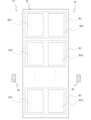
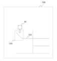
図1に示すように、自動搬送車10は、第1エリアA1、仮置きエリアB、第2エリアA2を含む走行エリアを走行し、各エリア間で台車C1,C2を搬送することができる。なお、台車C1は物品Pを積載した台車であり、台車C2は物品Pを積載しない空台車である。また本例では、搬送車10が台車C1、C2の下側に潜り込んで連結する構成としているが、これに限られない。第1エリアA1は、射出成型、プレス成型等の上流工程を行い、当該部品を台車に積載するエリアとすることができ、第2エリアA2は、塗装、組み立て等の下流工程を行うエリアとすることができるが、これに限られない。As shown in FIG. 1, the automated guided
図1に示すように、走行エリアには、複数の仮置きエリアBが通路を挟んで設定されている。図1において、第1エリアと第2エリアの間で、上下方向に延在する仮置きエリアBが、左右方向に間隔を空けて3列配置されているが、これに限られない。As shown in Fig. 1, a plurality of temporary storage areas B are set on either side of an aisle in the travel area. In Fig. 1, the temporary storage areas B extending in the vertical direction are arranged in three rows with a space between them in the horizontal direction between the first area and the second area, but this is not limited to this.
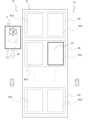
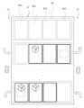
図2に示すように、仮置きエリアBは、所定物を積載した積載状態搬送物を仮置きする積載搬送物エリアB11と、前記所定物を積載していない非積載状態搬送物を仮置きする非積載搬送物エリアB12とを組み合わせた単位エリアB1が複数配列されて設定される。通路を挟んで隣り合う仮置きエリアBは、互いに積載搬送物エリアB11が向かい合うか、非積載搬送物エリアB12が向かい合うようになっている。換言すると、一の通路の両側には、共に積載搬送物エリアB11が隣接するか、共に非積載搬送物エリアB12が隣接する。As shown in Figure 2, the temporary placement area B is set up by arranging multiple unit areas B1 that combine a loaded item area B11 for temporarily placing loaded items carrying a specified item, and a non-loaded item area B12 for temporarily placing non-loaded items not carrying the specified item. Adjacent temporary placement areas B across an aisle are arranged so that the loaded item areas B11 face each other, or the non-loaded item areas B12 face each other. In other words, both sides of an aisle are adjacent to each other, either with loaded item areas B11 or with non-loaded item areas B12.
図2の例では、図2の横方向(第1方向)に積載搬送物エリアB11と非積載搬送物エリアB12とが隣接して設定される。また、図2の横方向(第1方向)に直行する縦方向(第2方向)に、単位エリアB1が複数配列される。In the example of Figure 2, a loaded transport area B11 and a non-loaded transport area B12 are set adjacent to each other in the horizontal direction (first direction) of Figure 2. In addition, multiple unit areas B1 are arranged in the vertical direction (second direction) perpendicular to the horizontal direction (first direction) of Figure 2.
また図2の例では、仮置きエリアBの左右両側の通路は互いに逆向きの一方通行(図の矢印M参照)となるように設定されている。例えば、積載搬送物エリアB11に隣接する通路T1は、第1エリアA1から第2エリアA2に向かう方向(図1,2の上側から下側に向かう方向)に設定され、非積載搬送物エリアB12に隣接する通路T2は、第2エリアA2から第1エリアA1に向かう方向(図1,2の下側から上側に向かう方向)に設定される。図1に示すように、複数の仮置きエリアBが通路を挟んで設定される場合、通路の両側の搬送物エリアは、積載状態が共通する搬送物エリアとすることが好ましい。つまり、第1エリアA1から第2エリアA2に向かう方向に移動方向が制限される通路T1を挟んで両側には、積載搬送物エリアB11が設定され、通路T2の両側には、非積載搬送物エリアB12が設定される。In the example of FIG. 2, the passages on both sides of the temporary storage area B are set to be one-way in the opposite directions (see arrow M in the figure). For example, the passage T1 adjacent to the loaded transport area B11 is set in the direction from the first area A1 to the second area A2 (from the top to the bottom in FIGS. 1 and 2), and the passage T2 adjacent to the non-loaded transport area B12 is set in the direction from the second area A2 to the first area A1 (from the bottom to the top in FIGS. 1 and 2). As shown in FIG. 1, when multiple temporary storage areas B are set on either side of the passage, it is preferable that the transport areas on both sides of the passage be transport areas with a common loading state. In other words, the loaded transport area B11 is set on both sides of the passage T1, whose movement direction is limited to the direction from the first area A1 to the second area A2, and the non-loaded transport area B12 is set on both sides of the passage T2.
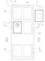
図3に示すように、第1エリアA1から物品Pを積載した積載台車C1を仮置きエリアBに搬送する場合、搬送車10の走行制御部は、空台車C2が置かれた非積載搬送物エリアB12に隣接する(又はもっとも近い位置にある)積載搬送物エリアB11を優先して目的地(移動目標位置)に決定する。換言すると、空台車C2が置かれた非積載搬送物エリアB12と単位エリアB1を構成する積載搬送物エリアB11を優先して目的地に決定する。なお、すでに積載台車C1が置かれた積載搬送物エリアB11には台車を置くことができないので、制御部は、少なくとも台車が置かれていない積載搬送物エリアB11を目標位置に決定する。その際、それぞれの積載搬送物エリアB11に台車があるか否かは、搬送車10に設けたセンサで検出するようにしてもよいし、走行エリア内に固定された固定カメラ等の検出部からの情報を取得して参照するようにしてもよい。このように、本システムにあっては、仮置きエリアの所定位置に台車が置かれているか否かに基づいて、どこに搬送物を搬送するかを決定してもよい。As shown in FIG. 3, when the loaded cart C1 loaded with the goods P is transported from the first area A1 to the temporary storage area B, the travel control unit of the
また、空台車C2が置かれた非積載搬送物エリアB12が複数存在する場合、その中で第1エリアA1から最も近い位置を優先して目的地を決定するようにしてもよいし、現在位置に最も近い位置を優先するようにしてもよい。また、その中で第1エリアA1から最も遠い位置を優先するようにしてもよいし、現在位置から最も遠い位置を優先するようにしてもよい。また、空台車C2が置かれた非積載搬送物エリアB12が存在しない場合、その中で第1エリアA1から最も近い位置を優先して目的地を決定するようにしてもよいし、現在位置に最も近い位置を優先するようにしてもよい。また、第1エリアA1から最も遠い位置を優先するようにしてもよいし、現在位置から最も遠い位置を優先するようにしてもよい。このような目標位置決定の条件は予め記憶部に記憶することができる。また、当該条件はユーザの入力情報に基づいて、記憶したり、更新したりすることができる。In addition, if there are multiple non-loaded transport areas B12 in which the empty trolley C2 is placed, the destination may be determined by giving priority to the position closest to the first area A1, or the position closest to the current position. In addition, the position farthest from the first area A1, or the position farthest from the current position may be prioritized. In addition, if there is no non-loaded transport area B12 in which the empty trolley C2 is placed, the destination may be determined by giving priority to the position closest to the first area A1, or the position closest to the current position. In addition, the position farthest from the first area A1, or the position farthest from the current position may be prioritized. Such conditions for determining the target position can be stored in advance in the storage unit. In addition, the conditions can be stored or updated based on the user's input information.
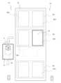
図4に示すように、積載搬送物エリアB11に積載台車C1を搬送して連結解除(切り離し)した後、搬送車10は図5に示すように、隣接する非積載搬送物エリアB12にある空台車C2を第1エリアA1に搬送することができる。As shown in Figure 4, after transporting the loaded trolley C1 to the loaded transport area B11 and disconnecting (disconnecting) it, the
また、図6に示すように、第2エリアA2から仮置きエリアBに空台車C2を搬送する場合、積載台車C1が置かれた積載搬送物エリアB11に隣接する(又はもっとも近い位置にある)非積載搬送物エリアB12を目的地(移動目標位置)に決定する。図7に示すように、非積載搬送物エリアB12に空台車C2を搬送して切り離し、隣接する積載搬送物エリアB11に置かれた積載台車C1を第2エリアA2に搬送することができる(図8参照)。As shown in Figure 6, when empty cart C2 is transported from second area A2 to temporary placement area B, the non-loaded goods area B12 adjacent (or closest) to loaded goods area B11 where loaded cart C1 is placed is determined as the destination (target movement position). As shown in Figure 7, empty cart C2 is transported to non-loaded goods area B12 and separated, and loaded cart C1 placed in the adjacent loaded goods area B11 can be transported to second area A2 (see Figure 8).
このように、第1エリアA1と第2エリアA2の間に位置する仮置きエリアBに台車を搬送する場合、台車を仮置きエリアBで切り離してから次の台車(仮置きエリアBにある台車)を連結するまでの搬送車の移動距離を短くすることで、搬送車を効率的に動かして台車を搬送することができる。In this way, when transporting a cart to temporary storage area B located between first area A1 and second area A2, the distance the transport vehicle travels from when the cart is detached at temporary storage area B to when the next cart (the cart in temporary storage area B) is coupled to it is shortened, so that the transport vehicle can be moved efficiently to transport the cart.
本システムにあっては、仮置きエリアBを経由せずに第1エリアA1から第2エリアA2に、または第2エリアA2から第1エリアA1に直接、台車を搬送してもよい。例えば、第2エリアA2に存在している積載台車C1が予め定めた数以下である場合、つまり、第2エリアA2で待機している積載台車C1が比較的少ない場合には、仮置きエリアBを経由せずに第1エリアA1から第2エリアA2に台車を搬送する。同様に、第1エリアA1で待機している空台車C2が比較的少ない場合には、仮置きエリアBを経由せずに第2エリアA2から第1エリアA1に台車を搬送するようにしてもよい。このように、第1エリアA1または第2エリアA2における台車の待機状況または混雑状況に基づいて、制御部が移動目標位置を決定するようにしてもよい。この場合、制御部は、台車の待機状況または混雑状況を取得する。台車の待機状況または混雑状況の情報は、例えば、第1エリアA1及び第2エリアA2に設置した固定カメラ等の固定検出装置、自動搬送車の検出部による各エリアの検出情報(台車の有無、台車の数の情報等)、または、作業者(ユーザ)が情報処理端末を介して入力した入力情報等から取得することができる。そして、制御部は、各種情報の何れか又はそれらの何れかの組み合わせに基づいて、移動目標位置を決定することができる。それぞれの搬送車は、走行しながら検出部で取得した検出情報を、作業者の端末(操縦機3000)や管理装置(統括制御装置4000)等の外部装置に送信することができる。管理装置は、取得した各種情報に基づいて、各エリアの情報を更新(記憶)することができる。In this system, the trolley may be transported directly from the first area A1 to the second area A2, or from the second area A2 to the first area A1, without passing through the temporary storage area B. For example, when the number of loaded trolleys C1 present in the second area A2 is equal to or less than a predetermined number, that is, when the number of loaded trolleys C1 waiting in the second area A2 is relatively small, the trolley is transported from the first area A1 to the second area A2 without passing through the temporary storage area B. Similarly, when the number of empty trolleys C2 waiting in the first area A1 is relatively small, the trolley may be transported from the second area A2 to the first area A1 without passing through the temporary storage area B. In this way, the control unit may determine the movement target position based on the waiting status or congestion status of the trolley in the first area A1 or the second area A2. In this case, the control unit acquires the waiting status or congestion status of the trolley. Information on the waiting status or congestion status of the trolleys can be obtained, for example, from fixed detection devices such as fixed cameras installed in the first area A1 and the second area A2, detection information for each area by the detection unit of the automatic guided vehicle (presence or absence of a trolley, information on the number of trolleys, etc.), or input information input by the worker (user) through an information processing terminal. Then, the control unit can determine the movement target position based on any of the various information or any combination of them. Each guided vehicle can transmit the detection information acquired by the detection unit while traveling to an external device such as the worker's terminal (control device 3000) or a management device (general control device 4000). The management device can update (store) the information for each area based on the acquired various information.
また、仮置きエリアBにおける台車の配置状況(空き状況を含む)、待機状況または混雑状況に基づいて、制御部が移動目標位置を決定するようにしてもよい。この場合、例えば、仮置きエリアBに設置した固定カメラ等の固定検出装置、自動搬送車の検出部による各エリアの検出情報(台車の有無、台車の数の情報等)、または、作業者(ユーザ)が情報処理端末を介して入力した入力情報等から仮置きエリアBにおける台車の待機状況または混雑状況を取得することができる。制御部は、仮置きエリアBにおける台車の待機状況または混雑状況に基づいて、移動目標位置を決定することができる。例えば、仮置きエリアが台車で埋まっている場合、仮置きエリアを通過して第1エリアA1または第2エリアA2に台車を搬送することができる。The control unit may also determine the target position for movement based on the arrangement status (including availability), waiting status, or congestion status of the trolleys in the temporary storage area B. In this case, the waiting status or congestion status of the trolleys in the temporary storage area B can be obtained from, for example, a fixed detection device such as a fixed camera installed in the temporary storage area B, detection information for each area (presence or absence of a trolley, information on the number of trolleys, etc.) by the detection unit of the automated guided vehicle, or input information input by the worker (user) via an information processing terminal. The control unit can determine the target position for movement based on the waiting status or congestion status of the trolleys in the temporary storage area B. For example, if the temporary storage area is filled with trolleys, the trolleys can be transported to the first area A1 or the second area A2 through the temporary storage area.
また、仮置きエリアBにおける全ての区画(積載搬送物エリアB11、非積載搬送物エリアB12)には、固有の識別情報(番号、ID等)が付与されていてもよい。そして、それぞれの区画における台車の有無を管理するようにしてもよい。また、当該識別情報を移動目標位置情報としてもよい。In addition, each section in the temporary storage area B (loaded transport area B11, non-loaded transport area B12) may be assigned unique identification information (number, ID, etc.). The presence or absence of a trolley in each section may be managed. The identification information may also be used as target position information.
図9乃至図12を用いて搬送車及び牽引される台車のハードウェア構成を説明する。図9は、本実施形態に係る搬送車のハードウェア構成例を示す斜視図である。本例の搬送車は無人搬送車であるが、人が乗ることが可能な各種車両にも適用可能である。図9の矢印15は搬送車の進行方向を示している。進行方向は、基本的に搬送車の前方であるが、状況に応じて後方でもあり得る。図9に示す通り、搬送車は、台車との連結と非連結状態を切り替えるための連結部11、搬送車周辺の物体を検出する物体位置検出部12、駆動輪13、非駆動輪14を備えている。The hardware configuration of the transport vehicle and the towed cart will be described using Figures 9 to 12. Figure 9 is a perspective view showing an example of the hardware configuration of the transport vehicle according to this embodiment. The transport vehicle in this example is an unmanned transport vehicle, but it can also be applied to various vehicles that people can ride in.
また、搬送車の上面側には、連結部11と、物体位置検出部12が搭載されている。連結部11は、例えばアクチュエータで構成され、台車と連結する場合にはアクチュエータを上側に伸ばして台車側の連結受け部(図示しない)と連結し、連結を解除する場合にはアクチュエータを縮めて連結部と台車側の連結受け部との連結を解除できるように構成されている。また、連結部11は、平面上で搬送車の駆動輪13を取り囲む4か所の位置に配置され、台車と5か所で連結可能となっている。本実施形態では4つの連結部を有する例を説明するが、連結部の数は必ずしも5個である必要は無く、1個以上の任意の数を選択可能である。搬送車と被搬送物との連結構造は特に限定されず、任意の連結構造を採用可能である。The upper surface of the transport vehicle is equipped with a connecting
物体位置検出部12は、搬送車から物体までの距離を検出する装置である。物体位置検出部12の一例としては、レーザー光を照射して物体に当たって跳ね返ってくるまでの時間を計測することで物体までの距離や方向を計測するレーザー距離センサ(LiDAR(Light detection and ranging)など)、ミリ波の送信信号と物体に反射して戻ってくる受信信号に基づいて物体までの距離を検出するミリ波レーダー、または、カメラで物体を撮影して撮影画像を解析することで物体までの距離を計測するカメラ式距離センサ、などを適用することができる。本実施形態では、物体位置検出部12を搬送車の上面部の進行方向前方に配置する例を示したが、これに替えて進行方向の前方側面に配置しても良い。また、前方だけでなく進行方向の後方側面や左右両側面に配置しても良い。The object
物体位置検出部12は、搬送車の周囲360度に対して物体を検出するようにしても良いが、少なくとも搬送車の進行方向15に対して物体を検出できるように構成されている。進行方向15は前方でも後方でもよい。The object
図10は、本実施形態に係る搬送車のハードウェア構成例を示す下面図である。搬送車の底面には、搬送車の進行方向15に対する左右両側の位置に駆動輪13が設けられ、各駆動輪13の前後の位置にはそれぞれ非駆動輪14が設けられる。駆動輪13は、モータの回転軸に接続されて駆動される車輪であり、右側の駆動輪と左側の駆動輪はそれぞれ個別に制御される。制御部は、駆動輪の回転速度を制御することにより、搬送車の速度を制御することができる。また制御部は、各駆動輪の回転速度や回転方向を個別に制御することにより、搬送車をカーブさせて走行させたり、その場で搬送車を回転させて向きを変えたり、停止させたり、後退させたりすることが可能となる。非駆動輪14は、駆動されない車輪で構成され駆動輪13により搬送車が移動することで受動的に回転する車輪である。非駆動輪14は、例えば、車輪と車軸を固定するフォークを有し、フォークは搬送車の底面部材と旋回可能に接続される回転キャスターで構成される。そのため、搬送車の進行方向や回転動作に応じて非駆動輪14の車輪回転方向が受動的に変化する。図10では、2つの駆動輪と、四隅に4つの非駆動輪を備える搬送車のハードウェア構成を例示したが、本発明は当該ハードウェア構成に限定されるものではなく、駆動輪2つと非駆動輪2つの計4輪の構成を採用することも可能であり、また当該4輪構成において前輪がステアリング可能となる構成を採用することも可能である。Figure 10 is a bottom view showing an example of the hardware configuration of the transport vehicle according to this embodiment. Drive
搬送車の底面には、誘導ライン(軌道ライン)を検出する誘導ライン検出部16が設けられている。誘導ライン検出部16は、望ましくは駆動輪13よりも搬送車の進行方向前方に設けられる。これにより、誘導ラインがカーブしている位置を走行する場合に誘導ラインに追従して走行しやすくなり、また搬送車及び牽引する台車が進行する際にいち早く誘導ラインから情報を受信することでいち早く停止等の処理が実行できる。誘導ライン検出部は、上述したような誘導方式のタイプに応じたセンサが用いられる。誘導方式として、電磁誘導方式を用いる場合はピックアップコイル、磁気誘導方式を用いる場合は磁気センサ、画像認識方式を用いる場合はカメラが誘導ライン検出部のセンサとして用いられる。軌道ラインは、床面に限られず、建物の側壁面、天井面等に設けられていてもよく、当該軌道ラインを認識可能な位置(搬送車の下面、側面、上面等)に搬送車のセンサ(カメラを含む)を設置することができる。また、軌道ラインは、2次元又は3次元のマップデータ上に仮想的に設けられた軌道であってもよい。搬送車の制御部は、予め記憶部に記憶されるマップ情報及び軌道情報(移動経路情報)と、カメラやセンサ等の情報に基づいて推定した現在の自己位置情報と、に基づいて、仮想的な軌道ラインに沿って搬送車の走行を制御するようにしてもよい。The bottom surface of the transport vehicle is provided with a
図11は、本実施形態に係る搬送車と牽引台車が結合された際のハードウェア構成の一例を示しており、具体的には、搬送車10が牽引対象である台車の下側に潜り込んだ状態で台車と連結する例を示している。この際、円錐形上の連結部11と対応する位置にすり鉢状の連結受け部が台車の底面に配置されており、連結部11を上側に伸ばすことで台車と連結でき、連結部11を縮めることで台車との連結を解除できる。Figure 11 shows an example of the hardware configuration when the transport vehicle and towing cart according to this embodiment are coupled, specifically showing an example in which the
図12は、本実施形態に係る搬送車と牽引台車が結合された際のハードウェア構成の他の一例を示している。図12に示す例では、搬送車は台車2000の横(台車の真下ではなく、前後左右の何れかにずれた位置)に位置する状態で台車と連結する例を示している。台車は、搬送車の連結部11の少なくとも一部と連結する連結受け部2010を備えており、連結部11を上側に伸ばすことで台車と連結でき、連結部11を縮めることで台車との連結を解除できる。図11や図12では、搬送車の上面にアクチュエータ等で構成される連結部11を上下方向に伸縮させることで、台車との連結と連結解除を行う例を示したが、搬送車と台車の連結方法はこれに限られず、他の連結方法であっても良い。また、搬送車と連結される搬送物は、台車に限られず、例えば、車輪を有さないパレットやキャビネット、コンベアやロボットアーム等であっても良い。パレットやキャビネットを搬送する場合には、搬送車はパレットやキャビネットの下側に潜り込んで、パレットやキャビネットを持ち上げた状態で連結される。Figure 12 shows another example of the hardware configuration when the transport vehicle and the towing dolly according to this embodiment are coupled. In the example shown in Figure 12, the transport vehicle is coupled to the dolly while being positioned to the side of the dolly 2000 (not directly under the dolly, but shifted to the front, rear, left or right). The dolly has a
図13は、本実施形態に係る動作エリア130の構成例を示す図である。なお、搬送車は、ガイドライン形式ではなく、自律走行形式のみで移動するものであってもよい。図13に示す通り、動作エリア130内には、誘導ライン131が敷設されており、自律走行モードで走行する搬送車が予め設定された走行モード切替位置132において誘導ライン131を検出した場合には、自律走行モードから誘導走行モードに走行制御モードが切り替えられる。また、逆に誘導ライン上を誘導走行モードで走行する搬送車が予め設定された走行モード切替位置132に入った場合には、誘導走行モードから自律走行モードに走行制御モードが切り替えられる。荷物が収納されている棚やベルトコンベヤや作業員の作業位置の近接位置に搬送車を誘導するために、誘導ライン131で構成される軌道は、複数の分岐点を介して、棚や作業位置と近接する位置に敷設されている。Figure 13 is a diagram showing an example of the configuration of the
誘導ラインの敷設されていない自律走行エリアを自律走行モードで走行している搬送車10は、走行モード切替位置132に進入し、かつ誘導ライン131を検出することを条件に誘導ラインに追従する誘導走行モードに走行モードを変更する。他方、誘導ライン上を誘導走行モードで走行する搬送車が走行モード切替位置132に進入した場合には、誘導走行モードから自律走行モードに走行制御モードが切り替わり、搬送車は誘導ラインを離脱して、自律走行を開始する。A guided
図13で示した誘導ライン131としては、後述するような、従来から利用されている様々な誘導方式の誘導ラインを適用することができる。具体的には、例えば、誘導ラインとして設置した金属線に微弱な交流電流を流すことで生じる磁場を搬送車側のピックアップコイルで検出する電磁誘導方式、誘導ラインとして床面に敷設した磁気テープを搬送車側の磁気センサで読み取る磁気誘導方式、または誘導ラインとして床面に敷設したコード(バーコード、二次元コードなど)の画像を搬送車側のカメラで撮影して画像処理を行う画像認識方式などを適用することができる。As the
<搬送システムの構成>
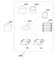
次に、本実施形態の搬送システムの構成を説明する。図14は、本実施形態に係る搬送システムの全体構成図の一例を示す図である。搬送システム1000は、複数の搬送車(10a, 10b)、搬送物である台車2000(搬送物の一例)、搬送車の状態を表示又は搬送車へ指令を入力可能な操縦機3000(ユーザ端末)、搬送車の運行に必要な情報を管理する統括制御装置4000、統括制御装置の情報を表示し統括制御装置に情報を入力する入出力装置5000、複数の搬送車(10a, 10b)と操縦機3000と統括制御装置4000を通信可能に接続する通信ネットワーク6000を備える。<Conveyor System Configuration>
Next, the configuration of the transport system of this embodiment will be described. Figure 14 is a diagram showing an example of the overall configuration of the transport system according to this embodiment. The
また、搬送システム1000は通信ネットワーク6000を介して外部システム7000と接続させることもできる。搬送システム1000を製造工場に導入して、製造に必要な部品を収納庫から製造ラインに搬送する場合には、搬送システム1000は、外部システム7000として製造管理システムとシステム間連携を行う。この場合、製造管理システムから製造作業の稼働進捗状況に関する情報を取得すれば、搬送車による輸送量や輸送経路を製造作業の作業進捗状況に応じて動的に調整することができる。The
別の例として、搬送システム1000を物流倉庫に導入して、トラック等で荷物が倉庫に搬入される際に搬入物を搬入口から収納庫に搬送し、また倉庫から荷物を出荷する際に収納庫から出荷される荷物を搬出口へ搬送する場合には、搬送システム1000は、外部システム7000として物流管理システムとシステム間連携を行う。この場合、物流管理システムから搬入に関する情報や出荷に関する情報を取得すれば、搬送車による輸送量や輸送経路を変更することができる。As another example, if the
搬送システムが導入される施設では、一般的に複数の搬送車(10a, 10b)が稼働するため、それぞれの搬送車は通信ネットワーク6000を介して他搬送車や他構成要素と通信可能に連結される。例えば、搬送車は自機の検出部で検出した各種検出情報やその他の制御情報を操縦機3000や統括制御装置4000や他搬送車10に送信する。また搬送車10は台車2000と電気的に接続又は近距離通信手段で通信可能に接続され、台車から連結状態に関する情報や台車の識別情報などを受信可能に構成される。In facilities where a transport system is installed, multiple transport vehicles (10a, 10b) are generally in operation, and each transport vehicle is communicatively connected to other transport vehicles and other components via a
操縦機3000は、各搬送車の状態情報を表示する機能と、指定した搬送車へ各種指令や各種情報を入力する機能を備えている。例えば、操縦機に表示される搬送車の状態情報としては、各搬送車の識別情報、位置(座標、マップ上での位置)、速度、向き、走行履歴、搬送車に搭載されて搬送車の電源となるバッテリの充電残量の情報、搬送車が搬送する台車等の搬送物の識別情報などである。また、操縦機には、各エリアの状況(搬送物の有無、待機数、不足数、仮置きエリアの搬送物の配置状況等)が表示される。また、操縦機には、マップ情報、搬送車の位置、搬送物の位置、物品の位置等が表示され得る。搬送車へ入力する指令としては、例えば、搬送車の目的地(移動目標位置)に関する指令情報、台車との連結や連結解除の動作指令、搬送車の走行開始指令、搬送車の停止指令、充電ステーションへの帰還指令などである。The
図15に本実施形態における統括制御装置4000の構成図を示す。統括制御装置4000は、施設エリアで運行される複数の搬送車の状態情報を記録する状態情報記録部4010と、複数の搬送車の動作シナリオを管理する動作シナリオ管理部4020と、搬送車の誘導ライン検出部により取得された誘導ラインの検出情報を含む搬送車の検出情報に基づいて作業エリアのマップを生成及び更新するマップ管理部4030と、搬送車の検出情報に基づいて誘導ライン及び搬送車の異常を判定する異常判定部4040と、外部の入出力装置5000及び通信ネットワーク6000と通信を行う通信部4050と、を有している。Figure 15 shows a configuration diagram of the
状態情報記録部4010で記録される搬送車の状態情報は、例えば、運行中の複数の搬送車により検出される搬送物の検出情報、障害物検出位置、誘導ライン検出位置、搬送車の走行位置の履歴情報、更には、バッテリ充電量の情報、複数の搬送車と連結された台車の識別情報、複数の搬送車の動作モード(誘導走行モードまたは自律走行モード)、その他搬送車の検出部230で検出される各種検出情報、作業エリアのマップ情報などである。動作シナリオ管理部4020で管理される動作シナリオは、例えば、複数の搬送車それぞれの目的地の情報、目的地に行き着くまでに実行する複数の動作内容、複数動作の動作順序、複数動作の切替条件を含んでいる。動作内容は、移動経路、どの搬送物をどこからどこに運ぶか、等の情報を含む。The status information of the transport vehicles recorded by the status information recording unit 4010 includes, for example, detection information of transported objects detected by multiple transport vehicles in operation, obstacle detection positions, guided line detection positions, history information of the transport vehicle's travel positions, and further information on the battery charge level, identification information of the trolleys connected to the multiple transport vehicles, the operation modes of the multiple transport vehicles (guided travel mode or autonomous travel mode), various other detection information detected by the transport
マップ管理部4030は、搬送車により検出される障害物検出位置、誘導ライン検出位置、搬送車の走行位置の履歴情報に基づいて、作業エリア内の障害物と誘導ラインの位置情報を含むマップを生成する。更に、マップ管理部4030は、1台又は複数台の搬送車により蓄積された誘導ラインの検出位置の情報に基づいて、マップに登録されている誘導ラインや作業エリアの情報を更新する。The map management unit 4030 generates a map including the position information of obstacles and guide lines in the work area based on the obstacle detection position, guide line detection position, and historical information of the travel position of the transport vehicle detected by the transport vehicle. Furthermore, the map management unit 4030 updates the information of the guide lines and work area registered in the map based on the information of the detection position of the guide lines accumulated by one or more transport vehicles.
異常判定部4040は、マップ情報に登録されている各エリア、搬送物、作業者、誘導ライン等の位置情報と、搬送車で検出される各エリア、搬送物、作業者、誘導ライン等の検出位置情報を含む搬送車の検出情報に基づいて、異常を判定する。The
入出力装置5000は、統括制御装置4000の状態情報記録部4010に記録された情報、マップ情報(マップの更新情報を含む)及び異常判定部による判定結果などを表示するとともに、動作シナリオ管理部4020で管理される動作シナリオを入力することで新規に動作シナリオを追加したり、更新したりすることができる。入出力装置5000に入力される情報は、例えば、任意の搬送車の目的地が仮置きエリアの特定の位置、第2エリア等であることや、走行経路、各エリアでの動作内容(連結、被連結)、動作条件などを含んでいる。The input/
<搬送車の機能>
図16を用いて搬送車の有する機能を説明する。図16は本実施形態に係る搬送車の機能構成図を示す図である。搬送車10は、搬送車外部の台車2000や通信ネットワーク6000と通信を行う通信部210と、記録部220(記憶部を含む)、後述する各種センサを備えた検出部230、台車と連結するための連結部11、車輪を駆動させる車輪駆動部280、入力部240、表示部250、車輪駆動部280などの動作を制御する制御部260、を備えている。<Functions of the transport vehicle>
The functions of the transport vehicle will be described with reference to Fig. 16. Fig. 16 is a diagram showing the functional configuration of the transport vehicle according to this embodiment. The
記録部220は、通信部210が外部から受信した情報、検出部230が検出した検出情報、制御部が生成、出力した情報を記録する機能を有する。記録部220は、搬送車の目的位置、移動経路、移動履歴等の情報を記憶することができる。記録部220は、目的位置までの距離に応じた速度情報、当該速度情報を算出するための算出式(プログラム)情報等を記憶することができる。The
検出部230は、物体位置検出部12、誘導ライン検出部16、走行距離検出部233、衝突検出部234、姿勢検出部235、充電量検出部236を備えている。物体位置検出部12は、前述した通り、レーザー光を照射して物体に当たって跳ね返ってくるまでの時間を計測することで物体までの距離や方向を計測するレーザー距離センサ(LiDAR(Light detection and ranging)など)、ミリ波の送信信号と物体に反射して戻ってくる受信信号に基づいて物体までの距離を検出するミリ波レーダー、または、カメラで物体を撮影して撮影画像を解析することで物体までの距離を計測するカメラ式距離センサ、などで構成される。制御部は、検出部の情報に基づいて、搬送車の現在位置、現在速度の情報を推定することができる。検出部230は、搬送車の現在位置を検出するGNSS等を含む位置センサ、搬送車の速度を検出する速度センサを備える。The
誘導ライン検出部16は、上述したように誘導方式のタイプに応じたセンサが用いられる。誘導方式として、電磁誘導方式を用いる場合はピックアップコイル、磁気誘導方式を用いる場合は磁気センサ、画像認識方式を用いる場合はカメラが誘導ライン検出部のセンサとして用いられる。誘導ライン検出部は、誘導ラインの直上に位置している場合に誘導ラインを検出して検出信号を出力する。また、カメラにより二次元コードやバーコードを使った誘導ラインを読み取る画像認識方式の場合には、誘導ラインの検出信号に加えて、検出したコードの情報に基づいて位置情報を生成し、更にコードの画像情報を行うことで誘導ラインと搬送車の相対角度情報を生成することができる。As described above, the guidance
走行距離検出部233は、非駆動輪14または駆動輪13の回転数を検出し、当該回転数の検出情報と非駆動輪または駆動輪の直径(または円周長)の情報に基づいて搬送車の走行距離及び走行速度を計測することができる(この場合、走行距離検出部233が、速度センサとして機能し得る)。また、代替手段として、ミリ波を水平方向等の任意の方向(壁面や床面等)に照射して反射波を検出するミリ波センサを用いて、搬送車の走行速度を検出し、当該走行速度を積分することで走行距離を推定する手段を適用することも可能である。また、上記した方法以外のあらゆる走行距離を計測したり、走行速度を取得したりする方法を適用可能である。The travel
衝突検出部234は、搬送車が物体や人に衝突したことを検出する機能を有する。具体的には、ジャイロセンサなどにより加速度を検出して、加速度の急変を検出した場合に衝突が発生したと判断することができる。代替手段として、搬送車の進行方向前方にバンパーと共に物理スイッチを設け、当該物理スイッチが押されたことにより衝突が発生したと判断する手段を適用することも可能である。また、上記以外の衝突検知方法を適用することができる。衝突検出部234が衝突を検出した場合には、搬送車を停止させ、衝突発生情報と衝突発生位置の少なくともいずれかの情報を記録部に記録すると共に、当該情報を統括制御装置4000及び操縦機3000に情報を通知する。姿勢検出部235は、磁気コンパス又は左右駆動輪の回転数の情報又は車輪のステアリング情報に基づいて、自車の向き(姿勢)を検出する。The
充電量検出部236は、搬送車の電源であるバッテリの充電量を検出する。充電量検出部236で検出した充電量が所定値以下となった場合には、充電が必要と判断して、充電量減少の検知情報を記録部に記録すると共に、当該情報を統括制御装置4000及び操縦機3000に情報を通知する。更に、充電量が所定値以下であることを検出した場合に、上記処理に加えて充電スポットへ自動で移動して充電を行うようにしても良い。なお、充電量検出部236が要充電と判断するための前記所定値は、当該搬送車に設定された目的地までの距離と当該搬送車に連結された搬送物の重量の少なくともいずれかに基づいて予め設定された値であっても良い。The charge
入力部240は、搬送車に搭載された物理スイッチ又はタッチパネル等で構成され、ユーザは動作指令等を直接搬送車に入力することができる。表示部250は、例えば、搬送車に搭載された液晶パネル等で構成され、搬送車の状態情報(検出部230での各種検出情報、走行モードの種別、現在実行中の動作シナリオなど)を表示することができる。The
制御部260は、動作判定部261と、モード切替部262と、連結制御部263と、表示制御部264と、位置推定部265(搬送車情報取得部)と、走行制御部266を備えている。動作判定部261は、動作シナリオ管理部4020から取得した自搬送車の動作シナリオに基づいて搬送車の動作を判定する。制御部260は、搬送車の移動目標位置を決定する目標位置決定部267と、仮置きエリアに配置される搬送物の情報を取得する搬送物情報取得部268と、を備える。The
モード切替部262は、動作シナリオ等により予め定められた条件、または入力部240で入力された指令に基づいて、搬送車の走行モードを誘導走行モードと自律走行モードの間でモードの切り替えを行う。連結制御部263は、動作シナリオ等で予め定められた条件、または入力部240で入力された指令に基づいて、連結部11の動作を制御して、台車等の搬送物との連結/非連結を制御する。表示制御部264は、前述した入力部240の入力IF及び表示部250を制御する。The
位置推定部265は、走行距離検出部233で検出した走行距離と、姿勢検出部235で検出した自車の向きの情報と、記録部220に記録されているエリア全体のマップ情報に基づいて、走行エリア全体における自車の現在位置を含む所定時刻の位置を推定することができる。または、物体位置検出部12で計測した自車から物体までの距離や方向の情報と、記録部220に記録されているエリア全体のマップ情報に基づいて走行エリア全体における自車の位置を推定することも可能である。あるいは、二次元コードで構成された誘導ライン上を走行している場合には、二次元コードの識別情報と上記マップ情報とに基づいて走行エリア全体における自車の位置を推定することも可能である。位置推定部265は、搬送車に設けたGNSS等によって位置情報を取得することも可能である。The
位置推定部265は、推定した自車位置情報と、物体位置検出部12で検出した自車から物体までの距離情報に基づいて、物体(搬送物、物品、人、障害物等)が存在する位置を推定することができる。また、誘導ライン検出部16で誘導ラインを検出した際の自車位置情報に基づいて、誘導ラインの設置位置を推定する。The
走行制御部266は、予め定められるマップ情報と、推定した自車位置情報と、移動目標位置の情報と、に基づいて、搬送車の走行を制御することができる。走行制御部266は、さらに、動作判定部261、モード切替部262による判定情報の少なくともいずれかに基づいて、搬送車の走行を制御することができる。走行制御部266は、搬送車の前進、後退、停止、旋回、及び移動速度、旋回速度を制御することができる。具体的には、車輪駆動部280の有する右輪駆動部281、左輪駆動部282をそれぞれ個別に制御する。右輪駆動部281と左輪駆動部282は例えばモーターで構成され、各駆動輪の回転速度や回転方向を個別に制御することで、搬送車を任意の軌跡半径でカーブさせて走行させたり、搬送車を回転させて向きを変えたりすることが可能となる。The
図17は、制御部による移動目標位置の決定処理の流れを示す。まず、所定のタイミングで、搬送車の制御部は、動作シナリオ情報を取得する(S101)。動作シナリオ情報は、例えば、搬送対象の搬送物に関する搬送対象物情報(識別情報、対象物の現在位置)、搬送開始位置、移動経路、目的地に関する情報を含むようにしてもよい。シナリオ情報は、具体的に、特定の識別番号の積載状態搬送物を第1エリアから仮置きエリアに搬送する、といった情報とすることができる。また、動作シナリオ情報に含まれる目的地の情報は、仮置きエリアBという広い範囲の情報でもよいし、仮置きエリアBにおける特定の区画(積載搬送物エリアB11、非積載搬送物エリアB12)という狭い範囲であってもよい。Figure 17 shows the flow of the process of determining the movement target position by the control unit. First, at a predetermined timing, the control unit of the transport vehicle acquires operation scenario information (S101). The operation scenario information may include, for example, transport target information (identification information, current position of the target object) regarding the transport target, transport start position, movement route, and destination information. Specifically, the scenario information may be information such as transporting a loaded transport target with a specific identification number from the first area to the temporary storage area. In addition, the destination information included in the operation scenario information may be information of a wide range such as the temporary storage area B, or may be information of a narrow range such as a specific section in the temporary storage area B (loaded transport target area B11, non-loaded transport target area B12).
次いで、制御部の搬送物情報取得部268は、各エリア(第1エリア、第2エリア、各仮置きエリア)に配置される搬送物の情報を取得する(S102)。搬送物の情報は、搬送物の有無、待機数、余剰数、不足数、積載物品の状態(積載物品の有無、積み込み中か否か、取出し中か否か)の少なくとも何れかを含むことができるが、これに限られない。Next, the transported goods
目標位置決定部267は、各エリアの搬送物の配置状況に基づいて、搬送車の移動目標位置を決定する(S103)。目標位置決定部267は、積載状態搬送物を搬送車で第1エリアから仮置きエリアに搬送する場合に、非積載状態搬送物が配置されていない非積載搬送物エリアに隣接する積載搬送物エリアよりも、非積載状態搬送物が配置されている非積載搬送物エリアに隣接する積載搬送物エリアを優先して、移動目標位置を決定する。例えば、空台車C2(非積載状態搬送物)が配置されている非積載搬送物エリアB12に隣接する積載搬送物エリアB11を目的地として、搬送車で積載台車C1を搬送する。このような構成により、当該目的地で積載台車C1を切り離した後に、すぐに隣の空台車C2を運び出すことができる。The target
走行制御部266は、予め定められるマップ情報と、推定した自車位置情報と、移動目標位置の情報と、に基づいて、搬送車の走行を制御する(S104)。走行制御部266は、マップ情報における現在の自車位置をスタート地点、移動目標位置をゴール地点として、通路Tを通る移動経路を生成し、当該移動経路に沿って自律走行するように搬送車の走行を制御する。その際、移動経路の一部を、予め設置される誘導ライン(ガイドライン)に沿って走行する誘導走行形式で走行制御するようにしてもよい。また、複数の通路が存在する場合、通路の選択は、通路の方向情報(一方通行の条件)に基づいて選択されるようにしてもよいし、方向情報が設定されていない場合には、移動距離が最も短くなるように設定してもよい。また、予め定められた優先順位に基づいて通路を選択してもよいし、障害物の位置、作業者の位置等に基づいて、選択するようにしてもよい。例えば、障害物の数がより少ない通路、作業者がいる通路(もしくは数が多い通路)、いない通路(もしくは数が少ない通路)を優先的に選択するようにしてもよい。これらの条件は、予め記憶部に記憶され、ユーザの入力に応じて更新され得る。The
さらに、目標位置決定部267は、各エリアにおける作業員の数(有無の情報を含む)、障害物の有無、通路の混雑状況(各通路における他の搬送車の位置またはその数、作業員の位置、)各エリアの稼働状況(停止していないかを含む)、予め定められた優先順位の何れか、又は複数の組み合わせに基づいて、移動目標位置を決定(もしくは更新)するようにしてもよい。例えば、作業者がいるエリアを優先して目的地を決定するようにしてもよいし、逆に作業者がいないエリアを優先して目的地を決定するようにしてもよい。あるいは、エリア自体に障害物がないエリア、または途中の通路に障害物や搬送車がないエリアを優先して目的地を決定するようにしてもよい。また、各エリアの稼働状況として、第1エリア、第2エリアの加工工程が停止している場合には、当該エリアに台車が溜まってしまう恐れがあるので、仮置きエリアに搬送することを優先するようにしてもよい。また、同条件の目標位置候補が複数ある場合、予め定められた優先順位が最も上位の位置を目標位置として決定してもよい。複数の条件を含む場合、各条件項目(作業員の数、障害物の数、稼働状況など)に優先順位を設定しておき、当該優先順位に基づいて移動目標位置を決定することも可能である。Furthermore, the target
さらに、目標位置決定部267は、搬送車の充電残量の情報、充電指令の情報、メンテナンス指令の少なくとも何れかの情報に基づいて、移動目標位置を決定(もしくは更新)するようにしてもよい。例えば、搬送物を搬送する搬送車の充電残量が所定の値以下であることを検出した場合、または充電指令やメンテナンス指令(搬送車のメンテナンスが必要である旨の指令や、故障を検出した場合などを含む)を取得した場合に、搬送物を仮置きエリアに搬送して連結解除し、充電やメンテナンスを行う位置に移動することができる。その際、搬送中の搬送物の種類に応じて、移動目標位置を決定できる。例えば、積載搬送物は積載搬送物エリアB11におき、非積載搬送物は非積載搬送物エリアB12に搬送することができるが、これに限られず、最も近い区画(積載搬送物エリアB11又は非積載搬送物エリアB12)を優先的に選択するようにしてもよい。Furthermore, the target
なお、統括制御装置4000の動作シナリオ管理部4020は、目標位置決定部として機能し得る。すなわち、各搬送車の移動目標位置を統括制御装置4000が決定し、各搬送車に指令として送信することができる。The operation
動作シナリオ管理部4020は、全ての又は一部の搬送車の現在位置の情報と、動作状況情報、充電残量等を取得する。動作状況とは、現在、搬送物を搬送しているか否か、また、次に何をするか(搬送するか、充電に向かうか等)といった情報である。The operation
そして、動作シナリオ管理部4020は、搬送待ちの搬送物の有無(識別情報を含む)及びその位置の情報を取得する。Then, the operation
そして、動作シナリオ管理部4020は、搬送待ちの搬送物の最も近くに位置し、すぐに搬送することができる搬送車(つまり、現在、搬送中でなく待機している、また、充電不足でない搬送車)を決定し、当該搬送車に対して、どの搬送物をどこからどこに搬送するかの情報を含む動作シナリオ情報を生成する。そいて、当該搬送車(及び、適宜他の搬送車にも)に、当該動作シナリオ情報の信号を送信する。これにより、当該信号を受信した搬送車が、動作シナリオ情報に基づく搬送動作をすることができる。The operation
目標位置決定部は、非積載状態搬送物を搬送車で第2エリアから仮置きエリアに搬送する場合に、積載状態搬送物が配置されていない非積載搬送物エリアに隣接する積載搬送物エリアよりも、積載状態搬送物が配置された非積載搬送物エリアに隣接する積載搬送物エリアを優先して移動目標位置を決定するようにしてもよい。これによれば、第2エリアから仮置きエリアに非積載搬送物を搬送してから、効率的に仮置きエリアの積載搬送物を第2エリアに搬送することができる。例えば、仮置きエリアに積載搬送物が予め定めた割合以上に配置されていて、待機エリア等から溢れそうもしくは、溢れて待機している場合、または、第2エリアにおける積載搬送物の待機が比較的少ない(あるいは不足している)場合に、特に有効である。したがって、なお、各エリアの状況に応じて、第2エリアから仮置きエリアに非積載搬送物を搬送した後(直後)に、そのまま搬送車単体で第1エリアを目標位置として移動してもよいし、仮置きエリアの非積載搬送物を第1エリアに搬送してもよい。例えば、第1エリアにおける搬送待ち状態の積載台車が予め定めた数を超えている場合には、迅速に搬送待ち状態の積載台車を搬送するために、搬送車単体で第1エリアに移動させることができる。また、第1エリアにおける積載待ちの空台車予め定めた数以下である(つまり空台車が不足している)場合には、仮置きエリアにある空台車(または第2エリアにある空台車)を第1エリアに搬送するように、移動目標位置を決定することができる。When the non-loaded transported object is transported from the second area to the temporary storage area by the transport vehicle, the target position determination unit may determine the movement target position by giving priority to the loaded transported object area adjacent to the non-loaded transported object area where the loaded transported object is placed, rather than the loaded transported object area adjacent to the non-loaded transported object area where the loaded transported object is not placed. According to this, the non-loaded transported object can be transported from the second area to the temporary storage area, and then the loaded transported object in the temporary storage area can be efficiently transported to the second area. For example, this is particularly effective when the loaded transported object is placed in the temporary storage area at a predetermined rate or more and is about to overflow from the waiting area or is overflowing and waiting, or when there are relatively few (or insufficient) loaded transported objects waiting in the second area. Therefore, depending on the situation of each area, after (immediately after) transporting the non-loaded transported object from the second area to the temporary storage area, the transport vehicle alone may move to the first area as the target position, or the non-loaded transported object in the temporary storage area may be transported to the first area. For example, when the number of loaded vehicles waiting for transport in the first area exceeds a predetermined number, the transport vehicle can be moved to the first area by itself in order to quickly transport the loaded vehicles waiting for transport. Also, when the number of empty vehicles waiting for loading in the first area is equal to or less than a predetermined number (i.e., there is a shortage of empty vehicles), a movement target position can be determined so that an empty vehicle in the temporary storage area (or an empty vehicle in the second area) is transported to the first area.
目標位置決定部は、搬送車の走行前、走行中の何れにおいても、移動目標位置の決定処理を行うことができ、繰り替えし行うことで、移動目標位置を変更(更新)することができる。例えば、第1エリアから仮置きエリアの特定の積載搬送物エリアB11に搬送物を搬送している最中に、当該積載搬送物エリアB11に障害物または人の存在を検出した場合には、当該検出情報を踏まえて再度目標位置決定処理を行い、選択される別の積載搬送物エリアB11に当該搬送物を搬送することができる。このように、搬送車の検出情報に基づいて、臨機応変に対応することができる。あるいは、搬送中に、移動目標位置の積載搬送物エリアB11の隣の非積載搬送物エリアB12の搬送物がなくなったことを示す情報を検出もしくは管理装置等から受信した場合、当該検出情報を踏まえて再度目標位置決定処理を行い、非積載搬送物エリアB12に搬送物が配置されている箇所の隣の積載搬送物エリアB11を選んで当該搬送物を搬送することも可能である。The target position determination unit can perform the determination process of the moving target position before and during the travel of the transport vehicle, and can change (update) the moving target position by repeating the process. For example, if an obstacle or a person is detected in a specific loaded transport area B11 of the temporary storage area while transporting a transported object from the first area, the target position determination process can be performed again based on the detection information, and the transported object can be transported to another selected loaded transport area B11. In this way, it is possible to respond flexibly based on the detection information of the transport vehicle. Alternatively, if information indicating that the transported object has disappeared in the non-loaded transport area B12 next to the loaded transport area B11 of the moving target position is detected or received from a management device, etc. during transport, the target position determination process can be performed again based on the detection information, and the loaded transport area B11 next to the location where the transported object is placed in the non-loaded transport area B12 can be selected and the transported object can be transported.
目標位置決定部は、積載状態搬送物を搬送車で第1エリアから積載搬送物エリアに搬送した直後に、当該積載搬送物エリアに隣接する非積載搬送物エリアに予め配置された非積載状態搬送物を第1エリアに搬送するように移動目標位置を決定するようにしてもよい。これによれば、第1エリアから積載搬送物エリアまで、且つ、非積載搬送物エリアから第1エリアまで、効率的に移動して搬送物を搬送することができる。The target position determination unit may determine a movement target position so that an unloaded transported object that has been placed in a non-loaded transported object area adjacent to the loaded transported object area is transported to the first area immediately after the loaded transported object is transported from the first area to the loaded transported object area by the transport vehicle. This allows the transported object to be transported by efficiently moving from the first area to the loaded transported object area and from the non-loaded transported object area to the first area.
目標位置決定部は、非積載状態搬送物を搬送車で第2エリアから非積載搬送物エリアに搬送した直後に、該非積載搬送物エリアに隣接する積載搬送物エリアに予め配置された積載状態搬送物を第2エリアに搬送するように移動目標位置を決定するようにしてもよい。これによれば、第2エリアから非積載搬送物エリアまで、且つ、積載搬送物エリアから第2エリアまで、効率的に移動して搬送物を搬送することができる。The target position determination unit may determine a movement target position so that a loaded transported object that has been placed in advance in a loaded transported object area adjacent to the unloaded transported object area is transported to the second area immediately after the unloaded transported object is transported from the second area to the unloaded transported object area by the transport vehicle. This allows the transported object to be transported efficiently by moving from the second area to the unloaded transported object area and from the loaded transported object area to the second area.
搬送車が、搬送物を検出する検出部を備え、目標位置決定部は、検出部からの搬送物検出情報に基づいて、移動目標位置を決定するようにしてもよい。これによれば、搬送車が各エリアの搬送物の有無及び位置を検出して、当該搬送物の情報に基づいて、自律的に移動目標位置を決定することができる。例えば、積載状態搬送物を搬送車で第1エリアから仮置きエリアに搬送する場合に、非積載状態搬送物が配置されている非積載搬送物エリアを検出して、そこに隣接する積載搬送物エリアを移動目標位置として選択することができる。なお、マップ情報は、仮置きエリアにおける積載搬送物エリア、非積載搬送物エリア等の位置情報を含むことができる。The transport vehicle may be equipped with a detection unit that detects transported goods, and the target position determination unit may determine the movement target position based on transported goods detection information from the detection unit. In this way, the transport vehicle can detect the presence and position of transported goods in each area, and autonomously determine the movement target position based on the information on the transported goods. For example, when a loaded transported goods is transported from a first area to a temporary storage area by the transport vehicle, a non-loaded transported goods area where a non-loaded transported goods is located can be detected, and a loaded transported goods area adjacent thereto can be selected as the movement target position. The map information may include position information of the loaded transported goods area, the non-loaded transported goods area, etc. in the temporary storage area.
仮置きエリアの周辺に固定設置され、仮置きエリアの搬送物を検出する固定検出部を備え、目標位置決定部は、固定検出部からの搬送物検出情報に基づいて、搬送車の移動目標位置を決定するようにしてもよい。これによれば、施設に固定設置されたカメラで取得した画像情報等を用いて、仮置きエリアにおける台車(積載台車、空台車)の有無、台数、積載状況等の情報を取得することができ、当該情報に応じて、適切な箇所を目的地を設定することができる。The system may include a fixed detection unit that is fixedly installed around the temporary storage area and detects transported items in the temporary storage area, and the target position determination unit may determine the target position for the transport vehicle based on transported item detection information from the fixed detection unit. This makes it possible to obtain information such as the presence, number, and loading status of carts (loaded carts and empty carts) in the temporary storage area using image information, etc., acquired by a camera fixedly installed in the facility, and to set the destination to an appropriate location depending on the information.
目標位置決定部は、さらに、第1エリアにおける搬送物の不足数情報に基づいて、搬送車の移動目標位置を決定するようにしてもよい。これによれば、第1エリアに搬送車が不足している場合(不足数が第1特定値以上、又は待機数が第2特定値以下など)には、第1エリアに空台車を搬送し、不足していない場合(不足数が第1特定値未満、又は待機数が第2特定値超など)には、仮置きエリアに空台車を搬送することができる。The target position determination unit may further determine a target position for the transport vehicle based on information on the shortage number of transported objects in the first area. According to this, if there is a shortage of transport vehicles in the first area (the shortage number is equal to or greater than a first specific value, or the waiting number is equal to or less than a second specific value, etc.), an empty vehicle can be transported to the first area, and if there is no shortage (the shortage number is less than the first specific value, or the waiting number is greater than the second specific value, etc.), an empty vehicle can be transported to the temporary storage area.
目標位置決定部は、さらに、第2エリアにおける搬送物の不足数情報に基づいて、搬送車の移動目標位置を決定するようにしてもよい。これによれば、第2エリアに搬送車が不足している場合(不足数が第1特定値以上、又は待機数が第2特定値以下など)には、第2エリアに積載台車を搬送し、不足していない場合(不足数が第1特定値未満、又は待機数が第2特定値超など)には、仮置きエリアに積載台車を搬送することができる。The target position determination unit may further determine a target position for the transport vehicle based on information on the shortage of transported objects in the second area. According to this, if there is a shortage of transport vehicles in the second area (the shortage is equal to or greater than a first specific value, or the waiting number is equal to or less than a second specific value, etc.), the loading cart can be transported to the second area, and if there is no shortage (the shortage is less than the first specific value, or the waiting number is greater than the second specific value, etc.), the loading cart can be transported to the temporary storage area.
図18に示すように、本実施形態における仮置きエリアBを構成する各単位エリアB1は、複数の積載搬送物エリアB11と、複数の非積載搬送物エリアB12との組み合わせであってもよい。これによれば、各単位エリアB1に複数の積載搬送物及び非積載搬送物を仮置きすることができる。この場合、積載搬送物が1つだけ配置される単位エリアB1よりも、積載搬送物が複数配置される単位エリアB1を優先して、非積載搬送物を搬送する際の移動目標位置として決定することができる。あるいは、その逆に、単位エリアB1に配置される搬送車の数が少ない単位エリアを優先して、移動目標位置を決定するようにしてもよい。図示例では、例えば、各単位エリアB1を構成する複数の積載搬送物エリアB11のうち、奥側(通路Tから遠い側)を優先して積載搬送物を配置する(仮置きする)ようにしてもよいし、その逆に、手前側(通路に近い側)から搬送物を配置するようにしてもよい。各単位エリアB1を構成する複数の非積載搬送物エリアB12も同様に、通路から見て奥側から優先して搬送物を仮置きしてもよいし、手前側がわ搬送物を仮置きするようにしてもよい。このような仮置きの優先順位は、予め記憶部に記憶され、ユーザの入力に応じて適宜更新され得る。図18の例では、隣接する2つの積載搬送物エリアB11と、2つの非積載搬送物エリアB12とが組み合わされているが、3以上の積載搬送物エリアB11と非積載搬送物エリアB12とが組み合わされていてもよい。As shown in FIG. 18, each unit area B1 constituting the temporary placement area B in this embodiment may be a combination of multiple loaded transport areas B11 and multiple non-loaded transport areas B12. According to this, multiple loaded transport items and non-loaded transport items can be temporarily placed in each unit area B1. In this case, the unit area B1 in which multiple loaded transport items are placed can be prioritized over the unit area B1 in which only one loaded transport item is placed, and can be determined as the movement target position when transporting the non-loaded transport item. Alternatively, conversely, the unit area in which the number of transport vehicles placed in the unit area B1 is small may be prioritized to determine the movement target position. In the illustrated example, for example, the loaded transport items may be placed (temporarily placed) in the back side (the side farther from the aisle T) of the multiple loaded transport areas B11 constituting each unit area B1, or conversely, the transport items may be placed from the front side (the side closer to the aisle). Similarly, the non-loaded transported goods areas B12 constituting each unit area B1 may be arranged so that the transported goods are temporarily placed in the order of priority from the back side as viewed from the passage, or the transported goods may be temporarily placed in the order of priority from the front side. Such a priority order of temporary placement may be stored in a storage unit in advance and updated as appropriate in response to a user's input. In the example of FIG. 18, two adjacent loaded transported goods areas B11 and two non-loaded transported goods areas B12 are combined, but three or more loaded transported goods areas B11 and non-loaded transported goods areas B12 may be combined.
また、本実施形態にあっては、各仮置きエリアBは、それぞれ逆向きの一方通行の通路に挟まれている。これによれば、第1エリア側から(必要に応じて仮置きエリアを経由して)第2エリア側に向かう場合と、第2エリア側から(必要に応じて仮置きエリアを経由して)第1エリア側に向かう場合とで、通路を別々にすることで移動経路が複雑になることを防ぎ、また、搬送車同士がすれ違うことを抑制できるので、狭い通路でも安全且つ効率的に搬送作業を行うことができる。In this embodiment, each temporary storage area B is sandwiched between two one-way passages going in opposite directions. This prevents the travel route from becoming complicated by using separate passages for traveling from the first area to the second area (via a temporary storage area if necessary) and traveling from the second area to the first area (via a temporary storage area if necessary). It also prevents transport vehicles from passing each other, so transport operations can be performed safely and efficiently even in narrow passages.
制御部260は、搬送車の速度センサで取得する速度情報に基づいて、走行制御処理を実行するようにしてもよい。速度センサの種類は特に限定されず、例えば駆動輪の回転数や回転速度を検出するセンサ等の任意のセンサや、カメラを速度センサとして用いることができる。制御部260は、予め定められる一定期間ごとに、搬送車の速度を検出し、当該速度が目標速度に一致しているかを判定して、繰り返し調整しながら走行制御することができる。すなわち、制御部260は、実際の速度と目標速度との差が所定値(予め定められた閾値等)以下であるか否かを判定し、所定値以下であれば制御を維持し、所定値を超えている場合には、目標速度に近づくように減速又は加速制御することができる。このような速度調整処理を繰り返すことで、目標速度からのずれを抑制(低減)することができる。制御部260は、搬送車の軌道ライン方向の速度、姿勢(向き)、軌道ラインに垂直な方向の位置の調整等の各種制御について、所謂フィードバック制御を行い、目標値になるように(目標値に近づくように)動作を調整することができる。The
制御部260は、路面に設置された2次元コードをセンサ(カメラ)でスキャンすることにより、2次元コードに関連付けられた現在位置、目的位置までの距離、及び/又はその地点での目標速度等の情報を取得するようにしてもよい。例えば、2次元コードに目標速度の情報を関連付けておけば、搬送車は2次元コードから目標速度の情報を取得し、上記速度制御を実行することができる。The
制御部260は、位置推定部265から取得する現在位置と、記憶部から取得する目的位置との差分に基づいて、搬送車の現在位置から目的位置までの距離を算出する処理を実行するようにしてもよい。あるいは、床面に敷設される二次元コードに距離の情報を関連付け、当該コードを搬送車で読み取ることにより、距離を取得するようにしてもよい。The
制御部260は、搬送車の速度センサで取得する速度情報に基づいて、搬送車の走行速度を制御するようにしてもよい。例えば、制御部260は、距離に基づいて決定した目標速度と、現在の搬送車の速度とを比較して、目標速度よりも現在速度が小さい場合には加速するよう制御し、目標速度よりも現在速度が大きい場合には、減速するよう制御する。The
制御部260は、予め定められる一定期間ごとに、現在位置を推定したり、移動目標位置を決定(更新)したり、位置を補正したりする処理を実行するようにしてもよい。一定期間は、例えば0.01秒、0.02秒、0.05秒、0.1秒、1秒等とすることができ、予め記憶部に記憶するようにしてもよい。制御部260は、一定期間に限られず、予め定められた所定の位置に移動した場合に、移動目標位置を決定(更新)したりすることができる。また、予め定められた所定イベントを検出した場合に、移動目標位置を決定(更新)するようにしてもよい。予め定められた所定イベントとは、例えば、人や他の搬送車や障害物への衝突、特定距離以内の接近、センサ情報や受信した情報から地震の発生を検出した場合、緊急停止装置が作動した場合、所定の動作シナリオが終了した場合等とすることができる。この場合、所定のイベントを検出すると、制御部は、上記の移動目標位置を決定する処理を行い、記憶部に記憶(更新)する。この所定イベント発生時の動作は、実行中の動作シナリオの途中で行ってもよく、その場合ば、動作シナリオの途中で移動目標位置を変更(更新)してもよい。The
制御部260は、路面、壁面、天井面等の特定箇所に設置された2次元コードをスキャンすることにより、前記現在位置を取得し、マップデータ状の位置を補正するようにしてもよい。これにより、簡易な方法で迅速に現在位置の情報を取得し、自己位置を補正することができる。The
また、搬送車は、上記のような現実の又は仮想の移動経路(もしくは誘導ライン)に沿う移動において、移動経路(もしくは誘導ライン)の延在方向に対する(例えば、誘導ラインの延在方向に対する)搬送車の姿勢(角度)を検出して、搬送車が移動経路方向に対して予め定められた所定値(例えば1°、5°など)以上ずれている場合に、姿勢を移動経路方向に近づけるように姿勢制御(旋回)するようにしてもよい。また、上記のような現実の又は仮想の移動経路(もしくは誘導ライン)に沿う移動において、移動経路(もしくは誘導ライン)に対する(例えば、誘導ラインの延在方向に対する)搬送車の横方向の位置のずれ量を検出して、搬送車が移動経路に対して予め定められた所定値(例えば1mm、5mm、10mmなど)以上ずれている場合に、横方向の位置のずれを補正して、ずれが小さくなる方向に走行制御するようにしてもよい。また、このような移動経路に対する姿勢または横ずれの検出は、所定期間(予め定められた一定期間、あるいは一定ではない所定期間)ごとに繰返し行うようにしてもよい。また、制御部は、例えば、搬送車の姿勢センサ等により、進行方向(搬送車の正面方向)を検出することができる。また、制御部は、検出部によりガイドラインの延在方向を検出するようにしてもよいし、予め記憶部のマップにガイドラインの位置及び延在方向のデータが記憶されていてもよい。In addition, when the transport vehicle moves along the real or virtual travel path (or guide line) as described above, the transport vehicle may detect the attitude (angle) of the transport vehicle relative to the extension direction of the travel path (or guide line) (for example, relative to the extension direction of the guide line), and if the transport vehicle deviates from the travel path direction by a predetermined value (for example, 1°, 5°, etc.) or more, the attitude may be controlled (turned) so that the attitude approaches the travel path direction. In addition, when the transport vehicle moves along the real or virtual travel path (or guide line) as described above, the amount of lateral positional deviation of the transport vehicle relative to the travel path (or guide line) (for example, relative to the extension direction of the guide line) may be detected, and if the transport vehicle deviates from the travel path by a predetermined value (for example, 1 mm, 5 mm, 10 mm, etc.) or more, the lateral positional deviation may be corrected and the travel control may be performed in a direction that reduces the deviation. In addition, such detection of the attitude or lateral deviation relative to the travel path may be performed repeatedly at predetermined intervals (predetermined fixed periods or non-fixed fixed periods). The control unit can detect the traveling direction (front direction of the transport vehicle) by, for example, a posture sensor of the transport vehicle, etc. The control unit may detect the extension direction of the guideline by the detection unit, or data on the position and extension direction of the guideline may be stored in advance in a map of the storage unit.
以上、添付図面を参照しながら本開示の好適な実施形態について詳細に説明したが、本開示の技術的範囲はかかる例に限定されない。本開示の技術分野における通常の知識を有する者であれば、特許請求の範囲に記載された技術的思想の範疇内において、各種の変更例または修正例に想到し得ることは明らかであり、これらについても、当然に本開示の技術的範囲に属するものと了解される。Although the preferred embodiment of the present disclosure has been described in detail above with reference to the attached drawings, the technical scope of the present disclosure is not limited to such examples. It is clear that a person with ordinary knowledge in the technical field of the present disclosure can conceive of various modified or revised examples within the scope of the technical ideas described in the claims, and it is understood that these also naturally fall within the technical scope of the present disclosure.
本明細書において説明した装置は、単独の装置として実現されてもよく、一部または全部がネットワークで接続された複数の装置(例えばクラウドサーバ)等により実現されてもよい。例えば、搬送車の制御部260および記録部220は、互いにネットワークで接続された異なるサーバにより実現されてもよい。また、本明細書において説明した搬送システムでは、操縦機3000、統括制御装置4000、入出力装置5000がそれぞれネットワークを介して接続された別個のハードウェアで構成される例を説明したが、操縦機3000、統括制御装置4000、入出力装置5000の機能の一部又は全部が搬送車10に実装されていても良い。The devices described in this specification may be realized as a single device, or may be realized by multiple devices (e.g., cloud servers) partially or completely connected via a network. For example, the
本明細書において説明した装置による一連の処理は、ソフトウェア、ハードウェア、及びソフトウェアとハードウェアとの組合せのいずれを用いて実現されてもよい。本実施形態に係る制御部260の各機能を実現するためのコンピュータプログラムを作製し、PC等に実装することが可能である。また、このようなコンピュータプログラムが格納された、コンピュータで読み取り可能な記録媒体も提供することができる。記録媒体は、例えば、磁気ディスク、光ディスク、光磁気ディスク、フラッシュメモリ等である。また、上記のコンピュータプログラムは、記録媒体を用いずに、例えばネットワークを介して配信されてもよい。The series of processes performed by the device described in this specification may be realized using software, hardware, or a combination of software and hardware. A computer program for realizing each function of the
また、本明細書においてフローチャート図を用いて説明した処理は、必ずしも図示された順序で実行されなくてもよい。いくつかの処理ステップは、並列的に実行されてもよい。また、追加的な処理ステップが採用されてもよく、一部の処理ステップが省略されてもよい。In addition, the processes described in this specification using flow chart diagrams do not necessarily have to be performed in the order shown. Some processing steps may be performed in parallel. Also, additional processing steps may be employed, and some processing steps may be omitted.
また、本明細書に記載された効果は、あくまで説明的または例示的なものであって限定的ではない。つまり、本開示に係る技術は、上記の効果とともに、または上記の効果に代えて、本明細書の記載から当業者には明らかな他の効果を奏しうる。In addition, the effects described herein are merely descriptive or exemplary and are not limiting. In other words, the technology disclosed herein may provide other effects that are apparent to a person skilled in the art from the description of this specification, in addition to or in place of the above effects.
なお、以下のような構成も本開示の技術的範囲に属する。
(項目1)
所定物が積載された搬送物を送り出す第1エリアと、前記所定物が積載された前記搬送物を受け入れる第2エリアと、前記第1エリア及び前記第2エリアの間に位置する仮置きエリアと、を含む走行エリアにおいて、前記搬送物を解除可能に連結して搬送する搬送車の制御システムであって、
前記走行エリアのマップ情報を記憶する記憶部と、
前記搬送車の現在位置情報を取得する搬送車情報取得部と、
各エリアに配置される搬送物の情報を取得する搬送物情報取得部と、
各エリアの搬送物の配置状況に基づいて、前記搬送車の移動目標位置を決定する目標位置決定部と、
前記マップ情報、前記搬送車の現在位置、及び、前記移動目標位置の情報に基づいて、前記搬送車の走行を制御する走行制御部と、を備え、
前記仮置きエリアは、前記所定物を積載した積載状態搬送物を仮置きする積載搬送物エリアと、前記所定物を積載していない非積載状態搬送物を仮置きする非積載搬送物エリアとを組み合わせた単位エリアが複数配列されて設定され、
前記目標位置決定部は、前記積載状態搬送物を前記搬送車で前記第1エリアから前記仮置きエリアに搬送する場合に、前記非積載状態搬送物が配置されていない前記非積載搬送物エリアに隣接する積載搬送物エリアよりも、前記非積載状態搬送物が配置されている前記非積載搬送物エリアに隣接する積載搬送物エリアを優先して、前記移動目標位置を決定する、搬送車の制御システム。
(項目2)
前記目標位置決定部は、前記非積載状態搬送物を前記搬送車で前記第2エリアから前記仮置きエリアに搬送する場合に、前記積載状態搬送物が配置されていない前記非積載搬送物エリアに隣接する積載搬送物エリアよりも、前記積載状態搬送物が配置された前記非積載搬送物エリアに隣接する積載搬送物エリアを優先して移動目標位置を決定する、項目1に記載の制御システム。
(項目3)
前記目標位置決定部は、前記積載状態搬送物を前記搬送車で前記第1エリアから前記積載搬送物エリアに搬送した直後に、該積載搬送物エリアに隣接する前記非積載搬送物エリアに予め配置された前記非積載状態搬送物を前記第1エリアに搬送するように前記移動目標位置を決定する、項目1または2に記載の制御システム。
(項目4)
前記目標位置決定部は、前記非積載状態搬送物を前記搬送車で前記第2エリアから前記非積載搬送物エリアに搬送した直後に、該非積載搬送物エリアに隣接する前記積載搬送物エリアに予め配置された前記積載状態搬送物を前記第2エリアに搬送するように前記移動目標位置を決定する、項目1または2に記載の制御システム。
(項目5)
前記搬送車が、周囲の物体又は人を検出する検出部を備え、
前記目標位置決定部は、走行中の搬送車の前記検出部からの検出情報に基づいて、前記移動目標位置を更新する、項目1または2に記載の制御システム。
(項目6)
前記仮置きエリアの周辺に固定設置され、前記仮置きエリアの搬送物を検出する固定検出部を備え、
目標位置決定部は、前記固定検出部からの搬送物検出情報に基づいて、前記搬送車の移動目標位置を決定する、項目1または2に記載の制御システム。
(項目7)
目標位置決定部は、さらに、前記第1エリアにおける搬送物の不足数情報に基づいて、前記搬送車の移動目標位置を決定する、項目1または2に記載の制御システム。
(項目8)
目標位置決定部は、さらに、前記第2エリアにおける搬送物の不足数情報に基づいて、前記搬送車の移動目標位置を決定する、項目1または2に記載の制御システム。
(項目9)
前記仮置きエリアは、互いに逆向きの一方通行の通路に挟まれている、項目1または2に記載の制御システム。
(項目10)
所定物が積載された搬送物を送り出す第1エリアと、前記所定物が積載された前記搬送物を受け入れる第2エリアと、前記第1エリア及び前記第2エリアの間に位置する仮置きエリアと、を含む走行エリアにおいて、前記搬送物を解除可能に連結して搬送する搬送車の制御方法であって、
制御部が、
前記走行エリアのマップ情報を記憶する記憶処理と、
前記搬送車の現在位置情報を取得する搬送車情報取得処理と、
各エリアに配置される搬送物の情報を取得する搬送物情報取得処理と、
各エリアの搬送物の配置状況に基づいて、前記搬送車の移動目標位置を決定する目標位置決定処理と、
前記マップ情報、前記搬送車の現在位置、及び、前記移動目標位置の情報に基づいて、前記搬送車の走行を制御する走行制御処理と、を実行し、
前記仮置きエリアは、前記所定物を積載した積載状態搬送物を仮置きする積載搬送物エリアと、前記所定物を積載していない非積載状態搬送物を仮置きする非積載搬送物エリアとを組み合わせた単位エリアが複数配列されて設定され、
前記目標位置決定処理は、前記積載状態搬送物を前記搬送車で前記第1エリアから前記仮置きエリアに搬送する場合に、前記非積載状態搬送物が配置されていない前記非積載搬送物エリアに隣接する積載搬送物エリアよりも、前記非積載状態搬送物が配置されている前記非積載搬送物エリアに隣接する積載搬送物エリアを優先して、前記移動目標位置を決定する、搬送車の制御方法。 Note that the following configurations also fall within the technical scope of the present disclosure.
(Item 1)
A control system for a transport vehicle that transports a transported object by releasably coupling the transported object in a travel area including a first area for sending out a transported object loaded with a predetermined object, a second area for receiving the transported object loaded with the predetermined object, and a temporary storage area located between the first area and the second area,
A storage unit that stores map information of the travel area;
a vehicle information acquisition unit that acquires current location information of the vehicle;
a transported goods information acquisition unit that acquires information on transported goods to be placed in each area;
a target position determination unit that determines a target position for the transportation vehicle based on the arrangement of the transported objects in each area;
a travel control unit that controls travel of the transport vehicle based on the map information, the current position of the transport vehicle, and the movement target position information,
The temporary placement area is set by arranging a plurality of unit areas each of which is a combination of a loaded transport area for temporarily placing a loaded transport item having the predetermined object loaded thereon and a non-loaded transport area for temporarily placing a non-loaded transport item not having the predetermined object loaded thereon;
A transport vehicle control system in which, when the loaded transport item is transported from the first area to the temporary storage area by the transport vehicle, the target position determination unit determines the movement target position by giving priority to a loaded transport item area adjacent to the non-loaded transport item area in which the unloaded transport item is placed, over a loaded transport item area adjacent to the non-loaded transport item area in which the unloaded transport item is not placed.
(Item 2)
The control system described in
(Item 3)
The control system described in
(Item 4)
The control system described in
(Item 5)
The transport vehicle includes a detection unit that detects surrounding objects or people,
3. The control system according to
(Item 6)
a fixed detection unit that is fixedly installed around the temporary placement area and detects the transported object in the temporary placement area;
3. The control system according to
(Item 7)
3. The control system according to
(Item 8)
3. The control system according to
(Item 9)
3. The control system according to
(Item 10)
A method for controlling a transport vehicle that transports a transported object by releasably coupling the transported object in a travel area including a first area for sending out a transported object loaded with a predetermined object, a second area for receiving the transported object loaded with the predetermined object, and a temporary storage area located between the first area and the second area, comprising:
The control unit:
A storage process for storing map information of the travel area;
A vehicle information acquisition process for acquiring current location information of the vehicle;
A transport item information acquisition process for acquiring information on transport items to be placed in each area;
a target position determination process for determining a target position for the transportation vehicle based on the arrangement of the transported object in each area;
a travel control process for controlling travel of the transport vehicle based on the map information, the current position of the transport vehicle, and the movement target position information;
The temporary placement area is set by arranging a plurality of unit areas each of which is a combination of a loaded transport area for temporarily placing a loaded transport item having the predetermined object loaded thereon and a non-loaded transport area for temporarily placing a non-loaded transport item not having the predetermined object loaded thereon;
The target position determination process is a control method for a transport vehicle, in which, when the loaded transport item is transported from the first area to the temporary storage area by the transport vehicle, the target position for movement is determined by giving priority to a loaded transport item area adjacent to the non-loaded transport item area in which the unloaded transport item is placed, over a loaded transport item area adjacent to the non-loaded transport item area in which the unloaded transport item is not placed.
10 搬送車、 11 連結部、 12 物体位置検出部、 13 駆動輪、 14 非駆動輪、 16 誘導ライン検出部、 17 磁気センサー、130 動作エリア、 131 誘導ライン、 132 走行モード切替位置、 210 通信部、 220 記録部、 230 検出部、 240 入力部、 250 表示部、 260 制御部、 280 車輪駆動部、2000 台車、 2010 連結受け部、 3000 操縦機、4000 統括制御装置、 5000 入出力装置、 6000 通信ネットワーク、 7000 外部システム10 Transport vehicle, 11 Connection unit, 12 Object position detection unit, 13 Drive wheel, 14 Non-drive wheel, 16 Guide line detection unit, 17 Magnetic sensor, 130 Operation area, 131 Guide line, 132 Travel mode switching position, 210 Communication unit, 220 Recording unit, 230 Detection unit, 240 Input unit, 250 Display unit, 260 Control unit, 280 Wheel drive unit, 2000 Cart, 2010 Connection receiving unit, 3000 Control unit, 4000 Overall control device, 5000 Input/output device, 6000 Communication network, 7000 External system
Claims (10)
Translated fromJapanese前記走行エリアのマップ情報を記憶する記憶部と、
前記搬送車の現在位置情報を取得する搬送車情報取得部と、
各エリアに配置される搬送物の情報を取得する搬送物情報取得部と、
各エリアの搬送物の配置状況に基づいて、前記搬送車の移動目標位置を決定する目標位置決定部と、
前記マップ情報、前記搬送車の現在位置、及び、前記移動目標位置の情報に基づいて、前記搬送車の走行を制御する走行制御部と、を備え、
前記仮置きエリアは、前記所定物を積載した積載状態搬送物を仮置きする積載搬送物エリアと、前記所定物を積載していない非積載状態搬送物を仮置きする非積載搬送物エリアとを組み合わせた単位エリアが複数配列されて設定され、
前記目標位置決定部は、前記積載状態搬送物を前記搬送車で前記第1エリアから前記仮置きエリアに搬送する場合に、前記非積載状態搬送物が配置されていない前記非積載搬送物エリアに隣接する積載搬送物エリアよりも、前記非積載状態搬送物が配置されている前記非積載搬送物エリアに隣接する積載搬送物エリアを優先して、前記移動目標位置を決定する、搬送車の制御システム。 A control system for a transport vehicle that transports a transported object by releasably coupling the transported object in a travel area including a first area for sending out a transported object loaded with a predetermined object, a second area for receiving the transported object loaded with the predetermined object, and a temporary storage area located between the first area and the second area,
A storage unit that stores map information of the travel area;
a vehicle information acquisition unit that acquires current location information of the vehicle;
a transported goods information acquisition unit that acquires information on transported goods to be placed in each area;
a target position determination unit that determines a target position for the transportation vehicle based on the arrangement of the transported objects in each area;
a travel control unit that controls travel of the transport vehicle based on the map information, the current position of the transport vehicle, and the movement target position information,
The temporary placement area is set by arranging a plurality of unit areas each of which is a combination of a loaded transport area for temporarily placing a loaded transport item having the predetermined object loaded thereon and a non-loaded transport area for temporarily placing a non-loaded transport item not having the predetermined object loaded thereon;
A transport vehicle control system in which, when the loaded transport item is transported from the first area to the temporary storage area by the transport vehicle, the target position determination unit determines the movement target position by giving priority to a loaded transport item area adjacent to the non-loaded transport item area in which the unloaded transport item is placed, over a loaded transport item area adjacent to the non-loaded transport item area in which the unloaded transport item is not placed.
前記目標位置決定部は、走行中の搬送車の前記検出部からの検出情報に基づいて、前記移動目標位置を更新する、請求項1または2に記載の制御システム。 The transport vehicle includes a detection unit that detects surrounding objects or people,
The control system according to claim 1 , wherein the target position determination unit updates the movement target position based on detection information from the detection unit of the transportation vehicle during travel.
目標位置決定部は、前記固定検出部からの搬送物検出情報に基づいて、前記搬送車の移動目標位置を決定する、請求項1または2に記載の制御システム。 a fixed detection unit that is fixedly installed around the temporary placement area and detects the transported object in the temporary placement area;
3. The control system according to claim 1, wherein the target position determination unit determines a target position for the transportation vehicle based on transported object detection information from the fixed detection unit.
制御部が、
前記走行エリアのマップ情報を記憶する記憶処理と、
前記搬送車の現在位置情報を取得する搬送車情報取得処理と、
各エリアに配置される搬送物の情報を取得する搬送物情報取得処理と、
各エリアの搬送物の配置状況に基づいて、前記搬送車の移動目標位置を決定する目標位置決定処理と、
前記マップ情報、前記搬送車の現在位置、及び、前記移動目標位置の情報に基づいて、前記搬送車の走行を制御する走行制御処理と、を実行し、
前記仮置きエリアは、前記所定物を積載した積載状態搬送物を仮置きする積載搬送物エリアと、前記所定物を積載していない非積載状態搬送物を仮置きする非積載搬送物エリアとを組み合わせた単位エリアが複数配列されて設定され、
前記目標位置決定処理は、前記積載状態搬送物を前記搬送車で前記第1エリアから前記仮置きエリアに搬送する場合に、前記非積載状態搬送物が配置されていない前記非積載搬送物エリアに隣接する積載搬送物エリアよりも、前記非積載状態搬送物が配置されている前記非積載搬送物エリアに隣接する積載搬送物エリアを優先して、前記移動目標位置を決定する、搬送車の制御方法。 A method for controlling a transport vehicle that transports a transported object by releasably coupling the transported object in a travel area including a first area for sending out a transported object loaded with a predetermined object, a second area for receiving the transported object loaded with the predetermined object, and a temporary storage area located between the first area and the second area, comprising:
The control unit:
A storage process for storing map information of the travel area;
A vehicle information acquisition process for acquiring current location information of the vehicle;
A transport item information acquisition process for acquiring information on transport items to be placed in each area;
a target position determination process for determining a target position for the transportation vehicle based on the arrangement of the transported object in each area;
a travel control process for controlling travel of the transport vehicle based on the map information, the current position of the transport vehicle, and the movement target position information;
The temporary placement area is set by arranging a plurality of unit areas each of which is a combination of a loaded transport area for temporarily placing a loaded transport item having the predetermined object loaded thereon and a non-loaded transport area for temporarily placing a non-loaded transport item not having the predetermined object loaded thereon;
The target position determination process is a control method for a transport vehicle, in which, when the loaded transport item is transported from the first area to the temporary storage area by the transport vehicle, the target position for movement is determined by giving priority to a loaded transport item area adjacent to the non-loaded transport item area in which the unloaded transport item is placed, over a loaded transport item area adjacent to the non-loaded transport item area in which the unloaded transport item is not placed.
Applications Claiming Priority (1)
| Application Number | Priority Date | Filing Date | Title |
|---|---|---|---|
| JP2024022433 | 2024-06-20 |
Publications (1)
| Publication Number | Publication Date |
|---|---|
| JP7575837B1true JP7575837B1 (en) | 2024-10-30 |
Family
ID=93254493
Family Applications (1)
| Application Number | Title | Priority Date | Filing Date |
|---|---|---|---|
| JP2024551591AActiveJP7575837B1 (en) | 2024-06-20 | 2024-06-20 | Transport vehicle control system and transport vehicle control method |
Country Status (1)
| Country | Link |
|---|---|
| JP (1) | JP7575837B1 (en) |
Citations (5)
| Publication number | Priority date | Publication date | Assignee | Title |
|---|---|---|---|---|
| JP2020154451A (en)* | 2019-03-18 | 2020-09-24 | 株式会社リコー | Autonomous mobile devices, programs and steering methods for autonomous mobile devices |
| JP2020154592A (en)* | 2019-03-19 | 2020-09-24 | 株式会社リコー | How to select objects to be transported by autonomous mobile devices, programs and autonomous mobile devices |
| JP2020191008A (en)* | 2019-05-23 | 2020-11-26 | 株式会社リコー | Autonomous mobile device, and conveyance information reading method for autonomous mobile device |
| JP2021086205A (en)* | 2019-11-25 | 2021-06-03 | 株式会社リコー | Identification member, autonomous mobile device, connection system and connection method |
| WO2024004021A1 (en)* | 2022-06-28 | 2024-01-04 | 株式会社Fuji | Transport device, transport system, and transport method |
- 2024
- 2024-06-20JPJP2024551591Apatent/JP7575837B1/enactiveActive
Patent Citations (5)
| Publication number | Priority date | Publication date | Assignee | Title |
|---|---|---|---|---|
| JP2020154451A (en)* | 2019-03-18 | 2020-09-24 | 株式会社リコー | Autonomous mobile devices, programs and steering methods for autonomous mobile devices |
| JP2020154592A (en)* | 2019-03-19 | 2020-09-24 | 株式会社リコー | How to select objects to be transported by autonomous mobile devices, programs and autonomous mobile devices |
| JP2020191008A (en)* | 2019-05-23 | 2020-11-26 | 株式会社リコー | Autonomous mobile device, and conveyance information reading method for autonomous mobile device |
| JP2021086205A (en)* | 2019-11-25 | 2021-06-03 | 株式会社リコー | Identification member, autonomous mobile device, connection system and connection method |
| WO2024004021A1 (en)* | 2022-06-28 | 2024-01-04 | 株式会社Fuji | Transport device, transport system, and transport method |
Similar Documents
| Publication | Publication Date | Title |
|---|---|---|
| JP7112803B1 (en) | Transport system and transport control method | |
| US20240059492A1 (en) | Conveyance system and conveyance control method | |
| JP7522516B1 (en) | Transport vehicle travel control system and transport vehicle travel control method | |
| JP7301409B2 (en) | Transport system and transport control method | |
| JP7575837B1 (en) | Transport vehicle control system and transport vehicle control method | |
| JP7669090B1 (en) | Information processing system, information processing method, and program | |
| JP7464331B1 (en) | Transport vehicle travel control system and transport vehicle travel control method | |
| JP7590802B1 (en) | Transport vehicle travel control system and transport vehicle travel control method | |
| JP7540815B1 (en) | Mobile object route generation system, route generation method, and program | |
| JP7659862B1 (en) | Route generation system, route generation method, and program for a mobile object | |
| JP7575836B1 (en) | Conveyor | |
| JP7513338B2 (en) | Transport system and transport control method | |
| JP7481058B1 (en) | TRANSPORT SYSTEM, TRANSPORT CONTROL METHOD, AND PROGRAM | |
| JP7509490B1 (en) | Coupling device | |
| JP2025146654A (en) | Mobile object route generation system, route generation method, and program | |
| JP2025146615A (en) | Mobile object route generation system, route generation method, and program | |
| JP2025146588A (en) | Mobile object route generation system, route generation method, and program | |
| JP2025155782A (en) | Mobile object route generation system, route generation method, and program | |
| JP2025155544A (en) | Mobile object route generation system, route generation method, and program |
Legal Events
| Date | Code | Title | Description |
|---|---|---|---|
| A621 | Written request for application examination | Free format text:JAPANESE INTERMEDIATE CODE: A621 Effective date:20240829 | |
| A871 | Explanation of circumstances concerning accelerated examination | Free format text:JAPANESE INTERMEDIATE CODE: A871 Effective date:20240829 | |
| TRDD | Decision of grant or rejection written | ||
| A01 | Written decision to grant a patent or to grant a registration (utility model) | Free format text:JAPANESE INTERMEDIATE CODE: A01 Effective date:20240926 | |
| A61 | First payment of annual fees (during grant procedure) | Free format text:JAPANESE INTERMEDIATE CODE: A61 Effective date:20241010 | |
| R150 | Certificate of patent or registration of utility model | Ref document number:7575837 Country of ref document:JP Free format text:JAPANESE INTERMEDIATE CODE: R150 |