JP7575243B2 - Radiation therapy device and method - Google Patents
Radiation therapy device and methodDownload PDFInfo
- Publication number
- JP7575243B2 JP7575243B2JP2020178651AJP2020178651AJP7575243B2JP 7575243 B2JP7575243 B2JP 7575243B2JP 2020178651 AJP2020178651 AJP 2020178651AJP 2020178651 AJP2020178651 AJP 2020178651AJP 7575243 B2JP7575243 B2JP 7575243B2
- Authority
- JP
- Japan
- Prior art keywords
- radiation
- irradiation
- dose
- gantry
- rotation speed
- Prior art date
- Legal status (The legal status is an assumption and is not a legal conclusion. Google has not performed a legal analysis and makes no representation as to the accuracy of the status listed.)
- Active
Links
Images


Classifications
- A—HUMAN NECESSITIES
- A61—MEDICAL OR VETERINARY SCIENCE; HYGIENE
- A61N—ELECTROTHERAPY; MAGNETOTHERAPY; RADIATION THERAPY; ULTRASOUND THERAPY
- A61N5/00—Radiation therapy
- A61N5/10—X-ray therapy; Gamma-ray therapy; Particle-irradiation therapy
- A61N5/1042—X-ray therapy; Gamma-ray therapy; Particle-irradiation therapy with spatial modulation of the radiation beam within the treatment head
- A61N5/1045—X-ray therapy; Gamma-ray therapy; Particle-irradiation therapy with spatial modulation of the radiation beam within the treatment head using a multi-leaf collimator, e.g. for intensity modulated radiation therapy or IMRT
- A61N5/1047—X-ray therapy; Gamma-ray therapy; Particle-irradiation therapy with spatial modulation of the radiation beam within the treatment head using a multi-leaf collimator, e.g. for intensity modulated radiation therapy or IMRT with movement of the radiation head during application of radiation, e.g. for intensity modulated arc therapy or IMAT
- A—HUMAN NECESSITIES
- A61—MEDICAL OR VETERINARY SCIENCE; HYGIENE
- A61N—ELECTROTHERAPY; MAGNETOTHERAPY; RADIATION THERAPY; ULTRASOUND THERAPY
- A61N5/00—Radiation therapy
- A61N5/10—X-ray therapy; Gamma-ray therapy; Particle-irradiation therapy
- A61N5/1077—Beam delivery systems
- A61N5/1081—Rotating beam systems with a specific mechanical construction, e.g. gantries
- A—HUMAN NECESSITIES
- A61—MEDICAL OR VETERINARY SCIENCE; HYGIENE
- A61N—ELECTROTHERAPY; MAGNETOTHERAPY; RADIATION THERAPY; ULTRASOUND THERAPY
- A61N5/00—Radiation therapy
- A61N5/10—X-ray therapy; Gamma-ray therapy; Particle-irradiation therapy
- A61N5/103—Treatment planning systems
- A61N5/1031—Treatment planning systems using a specific method of dose optimization
- A—HUMAN NECESSITIES
- A61—MEDICAL OR VETERINARY SCIENCE; HYGIENE
- A61N—ELECTROTHERAPY; MAGNETOTHERAPY; RADIATION THERAPY; ULTRASOUND THERAPY
- A61N5/00—Radiation therapy
- A61N5/10—X-ray therapy; Gamma-ray therapy; Particle-irradiation therapy
- A61N5/1048—Monitoring, verifying, controlling systems and methods
- A61N5/1064—Monitoring, verifying, controlling systems and methods for adjusting radiation treatment in response to monitoring
- A61N5/1068—Gating the beam as a function of a physiological signal
- A—HUMAN NECESSITIES
- A61—MEDICAL OR VETERINARY SCIENCE; HYGIENE
- A61N—ELECTROTHERAPY; MAGNETOTHERAPY; RADIATION THERAPY; ULTRASOUND THERAPY
- A61N5/00—Radiation therapy
- A61N5/10—X-ray therapy; Gamma-ray therapy; Particle-irradiation therapy
- A61N5/1048—Monitoring, verifying, controlling systems and methods
- A61N5/1049—Monitoring, verifying, controlling systems and methods for verifying the position of the patient with respect to the radiation beam
- A61N2005/1061—Monitoring, verifying, controlling systems and methods for verifying the position of the patient with respect to the radiation beam using an x-ray imaging system having a separate imaging source
- A—HUMAN NECESSITIES
- A61—MEDICAL OR VETERINARY SCIENCE; HYGIENE
- A61N—ELECTROTHERAPY; MAGNETOTHERAPY; RADIATION THERAPY; ULTRASOUND THERAPY
- A61N5/00—Radiation therapy
- A61N5/10—X-ray therapy; Gamma-ray therapy; Particle-irradiation therapy
- A61N2005/1085—X-ray therapy; Gamma-ray therapy; Particle-irradiation therapy characterised by the type of particles applied to the patient
- A61N2005/1087—Ions; Protons
Landscapes
- Health & Medical Sciences (AREA)
- Engineering & Computer Science (AREA)
- Biomedical Technology (AREA)
- Life Sciences & Earth Sciences (AREA)
- Pathology (AREA)
- Radiology & Medical Imaging (AREA)
- Nuclear Medicine, Radiotherapy & Molecular Imaging (AREA)
- Animal Behavior & Ethology (AREA)
- General Health & Medical Sciences (AREA)
- Public Health (AREA)
- Veterinary Medicine (AREA)
- Biophysics (AREA)
- Physiology (AREA)
- Radiation-Therapy Devices (AREA)
Description
Translated fromJapanese本明細書及び図面に開示の実施形態は、放射線治療装置及び方法に関する。 SUMMARY OF THE DISCLOSURE The embodiments disclosed herein and in the drawings relate to radiation therapy devicesand methods .
放射線治療は強度を変調したX線あるいは粒子線を複数方向から照射するIMRT(強度変調放射線療法:Intensity Modulated Radiation Therapy)、あるいはIMPT(強度変調粒子線療法:Intensity Modulated Particle Therapy)が主流である。しかしながら、これらの手法は、照射方向を変更する毎に患者位置を確認しなければならない、さらには照射方向の腫瘍より手前にある正常組織への被曝が大きくなるなどの問題があった。The mainstream radiation therapy is IMRT (Intensity Modulated Radiation Therapy), which irradiates intensity-modulated X-rays or particle beams from multiple directions, or IMPT (Intensity Modulated Particle Therapy). However, these methods have problems such as the need to check the patient's position every time the irradiation direction is changed, and also the fact that normal tissue in front of the tumor in the irradiation direction is exposed to a large amount of radiation.
これに対し、ガントリーを回転させながらX線あるいは粒子線を照射する方法が近年取られるようになってきている。ガントリーを回転させながらX線あるいは粒子線を照射する方法はVMAT(強度変調回転照射法:Volumetric Modulated Arc Therapy)と陽子線回転治療(Proton Arc Therapy)と呼ばれる。このような方法では、1)スループットが良い(患者位置を確認する回数が例えば1回の回転照射の場合1回で済む)、2)照射方向の腫瘍より手前にある正常組織への被曝が小さい、3)治療計画が簡単(照射角度を選択する必要がないので)、などのメリットがある。In response to this, a method of irradiating X-rays or particle beams while rotating the gantry has recently come into use. This method of irradiating X-rays or particle beams while rotating the gantry is called VMAT (Volumetric Modulated Arc Therapy) and Proton Arc Therapy. This method has the following advantages: 1) good throughput (patient position only needs to be checked once for one rotational irradiation, for example); 2) exposure to normal tissue in front of the tumor in the direction of irradiation is small; and 3) treatment planning is simple (since there is no need to select the irradiation angle).
VMATあるいは陽子線回転治療は治療計画から治療(患者位置合わせ、ビーム照射)までのスループットを大きく向上させることができる。このため、近い未来、超高齢化社会が訪れた場合、放射線治療の中心的役割を果たすようになると期待されている。VMAT or proton beam rotation therapy can greatly improve throughput from treatment planning to treatment (patient alignment and beam irradiation). For this reason, it is expected that it will play a central role in radiation therapy in the near future when we enter a super-aging society.
ここで、VMATあるいは陽子線回転治療は、上記したようにメリットが多いが、呼吸動のある臓器(肺、肝臓など)においては注意が必要となる。例えば、呼吸動のある臓器への治療には、1)呼吸しながら連続照射(呼吸で動く範囲+マージン分の広めの照射)、2)息止め照射、3)呼吸動の抑制(バンドなどでお腹を締めて、呼吸動を抑制)、4)ゲート照射(呼吸が所望の位相になった時のみ照射を行う)、5)トラッキング照射(腫瘍位置の変化をモニターし、腫瘍位置に合わせて照射)、などが知られている。しかしながら、1)は、正常組織への被曝が増える。2)は、息止めは健常者でも15秒程度しか安定してできないが、対象となる患者ではさらに短く、照射中の息止めはかなり難しい。3)は、患者への負担が大きく、さらに患者によっては抑制できない場合がある。5)は、がんそのものが見えないため、近くにある臓器の動きを元に推測するか、あるいはがん組織付近にマーカーを挿入することしかできないが、前者は臓器の動きと腫瘍の動きが相関するとは限らないと言う問題が、後者はマーカー挿入の手間とマーカーが逸脱するリスクなどがある。これらのことから、呼吸動のある臓器への治療においては、総じて、安定して実施できるのは、4)ゲート照射である。As mentioned above, VMAT and proton rotation therapy have many advantages, but care must be taken when treating organs with respiratory movement (lungs, liver, etc.). For example, known methods for treating organs with respiratory movement include 1) continuous irradiation while breathing (wide irradiation to cover the range of movement caused by breathing plus a margin), 2) breath-holding irradiation, 3) suppression of respiratory movement (tightening the abdomen with a band or the like to suppress respiratory movement), 4) gated irradiation (irradiation is performed only when breathing reaches the desired phase), and 5) tracking irradiation (monitoring changes in tumor position and irradiating according to the tumor position). However, 1) increases exposure to normal tissue. 2) Although healthy individuals can only hold their breath stably for about 15 seconds, this is even shorter for the target patients, and holding one's breath during irradiation is quite difficult. 3) places a heavy burden on the patient, and may not be possible for some patients. In 5), because the cancer itself cannot be seen, it is only possible to make an estimate based on the movement of nearby organs or to insert a marker near the cancer tissue, but the former has the problem that the movement of the organ and the movement of the tumor are not necessarily correlated, while the latter has the trouble of inserting the marker and the risk of the marker becoming dislodged. For these reasons, when it comes to treating organs with respiratory movement, 4) gated irradiation is generally the most reliable method.
VMATあるいは陽子線回転治療において、ゲート照射を行う方法は、大きく2種類ある。一つは照射期間の間だけガントリーを回転する方法と、もう一つは照射期間だけでなく、照射期間にある照射休止期間もガントリーを回転する方法である。前者は回転速度を遅くして、休止期間になったら直ぐに停止する必要がある。この方法では回転速度が遅いので、1回転に時間がかかると言う問題がある。さらに仮に休止期間の始まり時に止まれなかった場合、オーバーランしてしまうので、オーバーラン分の角度を逆回転して戻す必要がある。In VMAT or proton beam rotation therapy, there are two main methods for performing gated irradiation. One is to rotate the gantry only during the irradiation period, and the other is to rotate the gantry not only during the irradiation period but also during the radiation pauses within the irradiation period. With the former, it is necessary to slow down the rotation speed and stop it immediately when the pause period begins. This method has the problem that because the rotation speed is slow, it takes a long time to complete one rotation. Furthermore, if it is not possible to stop at the start of the pause period, it will overrun, so it is necessary to reverse the rotation angle to return to the amount of the overrun.
本明細書及び図面に開示の実施形態が解決しようとする課題の一つは、正常組織への被曝の増加を抑止しつつ、投与線量を安定して確保することである。ただし、本明細書及び図面に開示の実施形態により解決しようとする課題は上記課題に限られない。後述する実施形態に示す各構成による各効果に対応する課題を他の課題として位置づけることもできる。One of the problems that the embodiments disclosed in this specification and drawings attempt to solve is to ensure a stable administration dose while preventing an increase in exposure to normal tissue. However, the problems that the embodiments disclosed in this specification and drawings attempt to solve are not limited to the above problem. Problems corresponding to the effects of each configuration shown in the embodiments described below can also be positioned as other problems.
実施形態に係る放射線治療装置は、架台を回転させながら放射線を照射させ、被治療体の呼吸に基づいて、前記架台の回転中の放射線の照射及び停止を制御する放射線治療装置であって、検出部と、変更部と、制御部とを備える。検出部は、被治療体の呼吸を検出する。変更部は、前記被治療体の呼吸における前記放射線の照射の対象となる呼吸位相範囲に基づいて投与線量を予測し、投与線量が目標線量に到達するように、前記被治療体に対して照射する放射線の線量率及び架台の回転速度の少なくとも一方、あるいは両方を変更する。制御部は、前記放射線の線量率及び架台の回転速度の少なくとも一方、あるいは両方について、変更に応じた制御を実行する。A radiotherapy device according to an embodiment is a radiotherapy device that irradiates radiation while rotating a gantry and controls irradiation and stopping of radiation during rotation of the gantry based on the respiration of the subject, and includes a detection unit, a change unit, and a control unit. The detection unit detects the respiration of the subject. The change unit predicts an administration dose based on a respiratory phase range of the subject's respiration that is the target of irradiation with radiation, and changes at least one or both of the dose rate of radiation irradiated to the subject and the rotation speed of the gantry so that the administration dose reaches a target dose. The control unit executes control according to the change in at least one or both of the dose rate of radiation and the rotation speed of the gantry.
以下に添付図面を参照して、本願に係る放射線治療装置及び放射線治療方法の実施形態を詳細に説明する。なお、本願に係る放射線治療装置及び放射線治療方法は、以下に示す実施形態によって限定されるものではない。また、実施形態は、処理内容に矛盾が生じない範囲で他の実施形態や従来技術との組み合わせが可能である。The following describes in detail the embodiments of the radiation therapy apparatus and radiation therapy method according to the present application with reference to the attached drawings. Note that the radiation therapy apparatus and radiation therapy method according to the present application are not limited to the embodiments shown below. In addition, the embodiments can be combined with other embodiments or conventional techniques as long as no inconsistencies arise in the processing content.
(第1の実施形態)
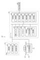
まず、本実施形態に係る放射線治療装置を含む放射線治療システムについて説明する。図1は、第1の実施形態に係る放射線治療システム1の構成の一例を示す図である。図1に示すように、第1の実施形態に係る放射線治療システム1は、治療計画用CT(Computed Tomography)装置100と、治療計画装置200と、放射線治療情報システム300と、放射線治療装置400とを含む。治療計画用CT装置100、治療計画装置200、放射線治療情報システム300、及び、放射線治療装置400は、ネットワーク2を介して、相互に通信可能に接続されている。なお、図1に示す構成はあくまでも一例であり、実施形態はこれに限定されるものではなく、例えば、その他種々の装置やシステムが放射線治療システム1に含まれる場合でもよい。First Embodiment
First, a radiation therapy system including a radiation therapy apparatus according to the present embodiment will be described. FIG. 1 is a diagram showing an example of the configuration of a
治療計画用CT装置100は、架台と、天板を有する寝台装置と、コンソールとを有し、天板に横臥した被治療体の治療対象部位(腫瘍など)を含むCT画像データを収集して、収集したCT画像データを治療計画装置200に送信する。具体的には、治療計画用CT装置100は、架台に備えられたX線管とX線検出器とを被治療体の周囲で回転させながら投影データを収集し、収集した投影データに基づいて3次元のCT画像データを再構成する。ここで、治療計画用CT装置100における天板は、放射線治療装置の天板と同様に平面形状を有している。The treatment planning CT device 100 has a gantry, a bed device with a tabletop, and a console, and collects CT image data including the treatment target site (such as a tumor) of a subject lying on the tabletop, and transmits the collected CT image data to the treatment planning device 200. Specifically, the treatment planning CT device 100 collects projection data while rotating an X-ray tube and an X-ray detector provided on the gantry around the subject, and reconstructs three-dimensional CT image data based on the collected projection data. Here, the tabletop in the treatment planning CT device 100 has a planar shape similar to the tabletop of a radiation therapy device.
なお、本実施形態では、治療計画用の画像データを収集する装置として、治療計画用CT装置100のみを示しているが、実施形態はこれに限られない。例えば、治療計画用MRI(Magnetic Resonance Imaging)装置や、超音波診断装置などによって治療計画用の3次元の画像データが収集される場合でもよい。In this embodiment, only the treatment planning CT device 100 is shown as a device that collects image data for the treatment plan, but the embodiment is not limited to this. For example, three-dimensional image data for the treatment plan may be collected by a treatment planning MRI (Magnetic Resonance Imaging) device, an ultrasound diagnostic device, or the like.
治療計画装置200は、治療計画用CT装置100により収集された被治療体の3次元のCT画像データを用いて、放射線治療装置400による放射線治療の治療計画を立てる。例えば、治療計画装置200は、治療計画用CT装置100が収集したCT画像データを用いて、被治療体内の治療対象部位の位置を特定する。また、例えば、治療計画装置200は、治療計画用CT装置100が収集したCT画像データを用いて、被治療体内のリスク臓器の位置を特定する。治療計画装置200は、CT画像データを用いて位置を特定した治療対象部位に対して所定の線量を投与し、さらにリスク臓器に対して所定の線量以下となるよう、放射線治療装置400が照射する放射線の照射角度や、照射角度ごとの線量及び照射野の形状、照射する回数などの計画を立てる。そして、治療計画装置200は、放射線治療情報システム300及び放射線治療装置400に対して治療計画を送信する。The treatment planning device 200 uses the three-dimensional CT image data of the subject collected by the treatment planning CT device 100 to create a treatment plan for radiation therapy using the
放射線治療情報システム300は、放射線治療に関する種々の情報を記憶して管理する。具体的には、放射線治療情報システム300は、治療計画や、CT画像データ、治療対象部位の位置と形状、リスク臓器の位置と形状、実績情報(照射履歴)、種々の報告、被治療体の状況の記録など、治療の進捗に関わる種々の情報を、被治療体ごとに記憶して管理する。放射線治療情報システム300は、ネットワーク2に接続された各装置からアクセスされ、管理する情報を提供することができる。The radiation therapy information system 300 stores and manages various information related to radiation therapy. Specifically, the radiation therapy information system 300 stores and manages various information related to the progress of treatment for each treated subject, such as treatment plans, CT image data, the position and shape of the area to be treated, the position and shape of organs at risk, performance information (irradiation history), various reports, and records of the condition of the treated subject. The radiation therapy information system 300 can be accessed by each device connected to the
放射線治療装置400は、治療計画装置200による治療計画に従い、被治療体に対して放射線を照射し、放射線治療を実行する。具体的には、放射線治療装置400は、架台を回転させながらX線或いは粒子線を照射する方法(VMATあるいは陽子線回転治療)によって放射線治療を行う。The
図2は、第1の実施形態に係る放射線治療装置400の一例を示す外観図である。なお、図2においては、治療室に設置された放射線治療装置400について示す。図2に示すように、放射線治療装置400は、放射線発生器412と、放射線絞り器414と、撮像装置(X線発生器411a及びX線検出器411b)とを有する架台と、天板422を有する寝台装置とを含み、図示しないコンソールからの制御に基づいて、放射線治療を行う。具体的には、放射線治療装置400は、放射線治療情報システム300から治療計画を取得する。そして、放射線治療装置400は、架台を矢印の方向に回転させることで治療計画に沿って、天板422に横臥した被治療体に対して放射線照射を行う。Figure 2 is an external view showing an example of a
放射線治療においては、まず、治療計画用CT装置100によって、治療計画を作成するために必要な3次元のCT画像データが収集される。ここで、被治療体の体勢の再現性及び保持性を高めるために固定具が作成される場合もある。また、被治療体は、放射線治療の各回において正確に放射線を照射させるための位置合わせに必要なマークが体表に付けられる。In radiation therapy, first, the treatment planning CT device 100 collects three-dimensional CT image data required to create a treatment plan. At this point, a fixation device may be created to improve the reproducibility and maintenance of the patient's posture. In addition, marks are placed on the patient's body surface to ensure accurate positioning so that radiation can be accurately delivered during each radiation therapy session.
そして、治療計画において、放射線の照射領域や、放射線の照射角度、照射角度ごとの線量及び照射野の形状、照射する回数などが決定される。例えば、放射線の照射領域の決定においては、まず、治療計画用CT装置100によって収集されたCT画像データなどに基づいて、放射線の照射を避けるべきリスク臓器が設定される。そして、腫瘍の進展や存在が肉眼的に確認できる3次元領域である肉眼的腫瘍体積(GTV:gross tumor volume)が設定され、設定されたGTV及び肉眼的には確認できないが潜在的な腫瘍領域を含む臨床的標的体積(CTV:clinical target volume)が設定される。なお、リスク臓器、GTC及びCTVの設定は、例えば、コンツーリング(輪郭の抽出)によって行われるが、コンツーリングは、医師による手動の処理及び画像処理技術による自動の処理のどちらでも行うことができる。In the treatment plan, the radiation irradiation area, radiation irradiation angle, dose and shape of the irradiation field for each irradiation angle, number of irradiations, etc. are determined. For example, in determining the radiation irradiation area, first, risk organs to which radiation should be avoided are set based on CT image data collected by the treatment planning CT device 100. Then, a gross tumor volume (GTV), which is a three-dimensional area in which the progression or presence of a tumor can be confirmed with the naked eye, is set, and a clinical target volume (CTV) is set that includes the set GTV and potential tumor areas that cannot be confirmed with the naked eye. The risk organs, GTC, and CTV are set, for example, by contouring (extraction of outlines), but the contouring can be performed either manually by a doctor or automatically using image processing technology.
そして、放射線の照射領域の決定においては、呼吸、嚥下、心拍動、蠕動などの体内臓器の動きによる影響を吸収するためのインターナルマージン(IM:internal margin)を含めたITV(internal target volume)がCTVに対して設定される。さらに、毎回の照射における設定誤差(SM:set-up margin)を含めた計画標的体積(PTV:planning target volume)がCTVに対して設定されることで、放射線の照射領域が決定される。When determining the radiation irradiation area, an internal target volume (ITV) including an internal margin (IM) to absorb the effects of internal organ movements such as breathing, swallowing, cardiac pulsation, and peristalsis is set for the CTV. Furthermore, a planning target volume (PTV) including the set-up margin (SM) for each irradiation is set for the CTV, thereby determining the radiation irradiation area.
このように、放射線の照射領域が決定されると、決定された照射領域に対する放射線の照射条件が設定される。例えば、治療計画装置200において、操作者(医療従事者)は、放射線の照射角度ごとの線量及び照射野の形状、照射回数などの照射条件を設定する。ここで、照射野の形状は、例えば、放射線絞り器513であるマルチリーフコリメータ(MLC:Multi-Leaf Collimator)によって形成される。MLCは、放射線の照射範囲を設定する複数の放射線遮蔽板を有し、治療計画に基づいて各遮蔽板が独立して駆動することで、放射線の照射領域(PTV)の形状に一致した照射野を形成することができる。In this way, once the radiation irradiation area is determined, the radiation irradiation conditions for the determined irradiation area are set. For example, in the treatment planning device 200, an operator (medical worker) sets irradiation conditions such as the dose for each radiation irradiation angle, the shape of the irradiation field, and the number of irradiations. Here, the shape of the irradiation field is formed, for example, by a multi-leaf collimator (MLC), which is the radiation constrictor 513. The MLC has multiple radiation shielding plates that set the radiation irradiation range, and each shielding plate is independently driven based on the treatment plan, making it possible to form an irradiation field that matches the shape of the radiation irradiation area (PTV).
このように作成された治療計画は、放射線治療情報システム300に送信され、患者情報、治療履歴などと一緒に管理される。放射線治療時には、治療計画は放射線治療情報システム300から放射線治療装置400に送信される。放射線治療装置400は、受信した治療計画に沿って、天板422に横臥した被治療体に対して放射線を照射する。The treatment plan created in this manner is sent to the radiation therapy information system 300 and managed together with patient information, treatment history, etc. During radiation therapy, the treatment plan is sent from the radiation therapy information system 300 to the
ここで、天板422に横臥する被治療体の中の放射線照射領域が、放射線治療装置400のアイソセンターに位置するように、レーザー照準器からのレーザーに対して被治療体の体表に付けられたマークが重なるように被治療体の体勢や寝台などが調整され、大まかな位置合わせが実行される。At this point, the position of the subject lying on the
その後、放射線治療装置400は、放射線の照射領域と放射線治療装置400のアイソセンターとの位置合わせを行うため、X線発生器411a及びX線検出器411bを含む撮像装置によって位置合わせ用のコーンビームCT画像データを生成する。例えば、放射線治療装置400は、架台を回転させながらX線発生器411aからX線を照射して、200度以上の角度分の投影データを収集し、収集した投影データに基づいて3次元のコーンビームCT画像データを再構成する。Then, the
放射線治療装置400は、再構成したコーンビームCT画像データと、治療計画用のCT画像データとを用いて、照射領域とアイソセンターとの位置合わせを実行する。なお、放射線治療装置400は、上記したコーンビームCT画像データを用いた位置合わせ以外にも、他の方法によって位置合わせを行うことができる。例えば、図2に示すように、撮像装置として、2つのX線撮影装置411cが治療室に設置される。放射線治療装置400は、天板422に横臥する被治療体を2つのX線撮影装置411cによって撮影し、得られた2方向のX線画像と、治療計画用のCT画像データから生成したDRR(Digitally Reconstructed Radiograph)とを比較することで、照射領域とアイソセンターとの位置合わせを実行する。なお、DRRとは、治療計画用のCT画像データを、2つのX線撮影装置411cによって撮影した2方向にそれぞれ投影することで得られる仮想的なX線撮像画像である。The
そして、放射線治療装置400は、治療計画に沿って放射線の照射を行う。ここで、本実施形態に係る放射線治療装置400は、VMAT或いは陽子線回転治療によって放射線治療を行う。具体的には、放射線治療装置400は、呼吸動のある臓器に対して、被治療体の呼吸が所望の位相になった時のみ照射を行うゲート照射による放射線治療を行う。The
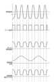
図3は、第1の実施形態に係るゲート照射を説明するための図である。図3においては、上段に呼吸信号を示し、下段にゲート信号を示す。例えば、ゲート照射では、被治療体から取得した呼吸信号に基づいて、放射線を照射させるためのゲート信号が送信され、ゲート信号がONとなっている時のみ放射線が照射される。Figure 3 is a diagram for explaining gated irradiation according to the first embodiment. In Figure 3, the upper part shows a respiratory signal, and the lower part shows a gate signal. For example, in gated irradiation, a gate signal for irradiating radiation is transmitted based on a respiratory signal acquired from the subject to be treated, and radiation is irradiated only when the gate signal is ON.
一例を挙げると、呼吸信号は、図3の上段に示すように、呼吸に応じた振幅を示す。ゲート照射では、呼吸信号の振幅に対して閾値a(例えば、振幅の30%)が設定され、呼吸信号が設定された閾値を下回っている間のみゲート信号がONとなり、ゲート信号がONの期間に放射線が照射される。As an example, the respiration signal shows an amplitude corresponding to respiration, as shown in the upper part of Figure 3. In gated irradiation, a threshold value a (e.g., 30% of the amplitude) is set for the amplitude of the respiration signal, and the gate signal is ON only while the respiration signal is below the set threshold, and radiation is irradiated during the period when the gate signal is ON.
ここで、呼吸は再現性がほぼないため、呼吸信号に基づくゲート信号の長さは1つ1つ異なるものとなる。また、時間と共に呼吸信号が上方向、或いは、下方向にシフトするベースラインシフトが発生すると、ゲート信号の長さが大きく変化するため、そのままゲート照射を行うと、目標投与線量から大きく外れる場合がある。例えば、放射線の線量率を治療計画のままとし、上方向にシフトした呼吸信号に基づいて回転照射を行うと、ゲート信号は、図3の下段よりも短くなり、その結果、目標投与線量よりも低くなる。一方、放射線の線量率を治療計画のままとし、下方向にシフトした呼吸信号に基づいて回転照射を行うと、ゲート信号は、図3の下段よりも長くなり、その結果、目標投与線量よりも高くなる。Here, because breathing is almost not reproducible, the length of the gate signal based on the breathing signal will be different for each one. Also, if a baseline shift occurs in which the breathing signal shifts upward or downward over time, the length of the gate signal will change significantly, and if gate irradiation is performed as is, it may deviate significantly from the target dose. For example, if the radiation dose rate remains the same as in the treatment plan and rotational irradiation is performed based on a breathing signal that has shifted upward, the gate signal will be shorter than the lower part of Figure 3, and as a result, the dose will be lower than the target dose. On the other hand, if the radiation dose rate remains the same as in the treatment plan and rotational irradiation is performed based on a breathing signal that has shifted downward, the gate signal will be longer than the lower part of Figure 3, and as a result, the dose will be higher than the target dose.
そこで、本実施形態に係る放射線治療装置400は、被治療体の呼吸をモニターし、モニターの結果に基づいて、被治療体に対して照射する放射線の線量率及び架台の回転速度の少なくとも一方を変更することで、正常組織への被曝の増加を抑止しつつ、投与線量を安定して確保することを可能にする。The
以下、本実施形態に係る放射線治療装置400の詳細について説明する。図4は、第1の実施形態に係る放射線治療装置400の構成の一例を示す図である。図4に示すように、放射線治療装置400は、架台410と、寝台装置420と、コンソール430とを有し、呼吸位相検出器500が接続される。The
呼吸位相検出器500は、被治療体の呼吸情報を取得して、取得した呼吸情報を示す呼吸信号をコンソール430に送信する。例えば、呼吸位相検出器500は、被治療体の腹部周りにベルトをはめ、ベルトにかかる張力に基づいて呼吸を検出する検出器、腹部に棒状の接触部を接触させ、接触部に加わる圧力に基づいて呼吸を検出する検出器、鼻や口に空気の流量を測るセンサを付け、鼻や口からの空気の流量に基づいて呼吸を検出する検出器、体表の形状をリアルタイムに計測し、腹部あるいは胸部の位置に基づいて呼吸を検出する検出器などである。また、呼吸位相を検出する手法としては、撮像装置411によってX線画像をリアルタイムで撮像し、撮像した画像における横隔膜の位置などから呼吸を検出する手法が用いられる場合でもよい。かかる場合には、呼吸位相を検出する手段が、放射線治療装置400に含まれることとなる。The
架台410は、撮像装置411と、放射線発生器412と、放射線絞り器413とを含む。撮像装置411は、X線発生器411a及びX線検出器411bを備え、コンソール430による制御のもと、寝台装置420に載置された被治療体のコーンビームCT画像データを収集するための撮影を行う。具体的には、撮像装置411は、撮影用のX線を照射するX線発生器411aと、撮影用のX線を検出するX線検出器411bとが被治療体を挟んで対向するように配置される。そして、撮像装置411は、架台410の回転中にX線発生器411aからX線を照射して、X線検出器411bによってX線を検出することで、200度以上の角度分の投影データを収集する。撮像装置411は、収集した投影データをコンソール430に送信する。The
放射線発生器412は、図示しない電子銃と加速管を備える。加速管は、電子銃から発生した熱電子を加速し、タングステンターゲットに衝突させて治療用の放射線を放射する。The
放射線絞り器413は、例えば、MLCであり、治療用の放射線の照射範囲を設定する複数の放射線遮蔽板を有する。例えば、放射線絞り器413は、コンソール430からの制御に応じて、図示しない移動機構によって複数の放射線遮蔽版を独立して移動させることで被治療体の照射領域に対応した形状を有する放射線の照射野を形成する。The
寝台装置420は、基台421と、天板422とを有する。基台421は、寝台駆動装置423が内蔵され、天板422を移動可能に支持する。天板422は、平面形状を有し、被治療体が載置される。寝台駆動装置423は、モータ及びアクチュエータ等を含み、コンソール430による制御のもと、天板422を移動させる。The
コンソール430は、通信インターフェース431と、入力インターフェース432と、ディスプレイ433と、記憶回路434と、処理回路435とを有する。The
通信インターフェース431は、処理回路435に接続され、ネットワーク2を介して接続された各装置との間で行われる各種データの伝送及び通信を制御する。例えば、通信インターフェース431は、ネットワークカードやネットワークアダプタ、NIC(Network Interface Controller)等によって実現される。The
入力インターフェース432は、処理回路435に接続され、操作者(医療従事者)から受け付けた入力操作を電気信号に変換して処理回路435に出力する。具体的には、入力インターフェース432は、操作者から受け付けた入力操作を電気信号へ変換して処理回路435に出力する。例えば、入力インターフェース432は、トラックボール、スイッチボタン、マウス、キーボード、操作面へ触れることで入力操作を行うタッチパッド、表示画面とタッチパッドとが一体化されたタッチスクリーン、光学センサを用いた非接触入力回路、及び音声入力回路等によって実現される。なお、本明細書において、入力インターフェース432は、マウス、キーボード等の物理的な操作部品を備えるものだけに限られない。例えば、装置とは別体に設けられた外部の入力機器から入力操作に対応する電気信号を受け取り、この電気信号を制御回路へ出力する電気信号の処理回路も入力インターフェース432の例に含まれる。The input interface 432 is connected to the
ディスプレイ433は、処理回路435に接続され、処理回路435から出力される各種情報及び各種画像データを表示する。例えば、ディスプレイ433は、液晶ディスプレイやCRT(Cathode Ray Tube)ディスプレイ、有機ELディスプレイ、プラズマディスプレイ、タッチパネル等によって実現される。本実施形態では、例えば、ディスプレイ433は、治療計画や照射履歴などを表示する。The
記憶回路434は、処理回路435に接続され、各種データを記憶する。例えば、記憶回路434は、RAM(Random Access Memory)、フラッシュメモリ等の半導体メモリ素子や、ハードディスク、光ディスク等によって実現される。一例を挙げると、記憶回路434は、呼吸位相情報434aや、照射履歴434bなどを記憶する。また、記憶回路434は、放射線治療情報システム300から受信した治療計画や、各種処理結果などを記憶する。また、記憶回路434は、処理回路435によって実行される各種機能に対応するプログラムを記憶する。The memory circuitry 434 is connected to the
呼吸位相情報434aは、呼吸位相検出器500によって検出された被治療体の呼吸情報である。例えば、呼吸位相情報434aは、天板422に載置された被治療体から取得した呼吸信号である。The respiratory phase information 434a is respiratory information of the treated subject detected by the
照射履歴434bは、被治療体に対して実際に照射された放射線の照射条件や、線量分布などを含み、放射線照射が実行されるごとに記憶回路434に格納される。照射履歴434bは、放射線照射が完了するごとに、放射線治療情報システム300に送信され、放射線治療情報システム300によって管理される。The irradiation history 434b includes the irradiation conditions of the radiation actually irradiated to the treated subject, the dose distribution, and the like, and is stored in the memory circuitry 434 each time radiation irradiation is performed. The irradiation history 434b is transmitted to the radiation therapy information system 300 each time radiation irradiation is completed, and is managed by the radiation therapy information system 300.
処理回路535は、入力インターフェース432を介して操作者から受け付けた入力操作に応じて、放射線治療装置400全体の動作を制御する。例えば、処理回路435は、プロセッサによって実現される。図3に示すように、処理回路435は、制御機能435a、検出機能435b、撮像機能435c、再構成機能435d、同定機能435e及び変更機能435fを実行する。ここで、制御機能435aは、制御部の一例である。また、検出機能435bは、検出部の一例である。また、変更機能435fは、変更部の一例である。The processing circuitry 535 controls the operation of the entire
制御機能435aは、入力インターフェース432を介して入力された各種要求に応じた処理を実行するように制御する。例えば、制御機能435aは、通信インターフェース431を介した情報(例えば、治療計画や、照射履歴など)の送受信、記憶回路434への情報の格納、ディスプレイ433への情報の表示などを制御する。The
また、制御機能435aは、治療計画に基づく制御信号を送信することで、架台410の回転、放射線発生器412による放射線の照射、放射線絞り器414における放射線遮蔽版の移動などを制御する。また、制御機能435aは、治療計画に基づく制御信号を送信することで、寝台装置420における寝台駆動装置423を制御して、天板422の移動を制御する。In addition, the
ここで、制御機能435aは、架台410を回転させながら放射線を照射する放射線治療を制御する。具体的には、制御機能435aは、架台410を回転させながら放射線を照射させ、被治療体の呼吸に基づいて、架台410の回転中の放射線の照射及び停止を制御する。より具体的には、制御機能435aは、架台410に対して制御信号を送信することで、架台410を回転させる。さらに、制御機能435aは、検出機能435bによって検出された被治療体の呼吸信号と閾値との比較によりゲート信号を架台410に送信することで、被治療体の呼吸信号に基づくゲート照射による放射線治療を制御する。また、制御機能435aは、変更機能435fによって変更された線量率による放射線照射、及び、変更機能435fによって変更された回転速度での架台410の回転を制御する。なお、上記制御については、後に詳述する。Here, the
検出機能435bは、被治療体の呼吸を検出する。具体的には、検出機能435bは、呼吸位相検出器500からの信号に受診することで、被治療体の呼吸信号を検出する。The
撮像機能435cは、撮像装置411を制御して、コーンビームCT画像データを再構成するための投影データを収集する。具体的には、撮像機能435cは、架台410の回転、X線発生器411aによるX線の照射、X線検出器411bによるデータ収集を制御する。例えば、撮像機能435cは、架台410を200度以上回転させながら、X線発生器411aにX線を照射させて、X線検出器411bにてデータを収集することで、被治療体の周囲200度以上の角度分の投影データを収集する。ここで、ゲート照射による放射線治療を行う場合、撮像機能435cは、呼吸位相検出器500から受信した呼吸信号に基づいて呼気に限定して投影データを収集する場合でもよく、呼吸信号に関わらず連続的に投影データを収集する場合でもよい。そして、撮像機能435cは、収集した投影データを記憶回路434に格納する。The imaging function 435c controls the imaging device 411 to collect projection data for reconstructing cone beam CT image data. Specifically, the imaging function 435c controls the rotation of the
また、治療室に2つのX線撮影装置411cが設置されている場合、撮像機能435cは、2つのX線撮影装置411cを制御して、2方向のX線画像を収集し、収集した2方向のX線画像を記憶回路434に格納する。ここで、ゲート照射による放射線治療を行う場合、撮像機能435cは、呼吸位相検出器500から受信した呼吸信号に基づいて、呼気にX線画像を収集する。When two
再構成機能435dは、撮像機能435cによって収集された投影データから各種画像を生成し、生成した画像を記憶回路434に格納する。例えば、再構成機能435dは、呼気に限定して収集された投影データを種々の再構成法によって再構成することでコーンビームCT画像データを再構成し、再構成したコーンビームCT画像データを記憶回路434に格納する。あるいは、再構成機能435dは、呼吸信号に関わらず連続的に投影データを呼吸位相毎の投影データに分割し、位相毎に種々の再構成法によって再構成することでコーンビームCT画像データ(4Dデータ)を再構成し、再構成したコーンビームCT画像データを記憶回路434に格納する。The
同定機能435eは、画像データに基づいて、放射線治療装置400におけるアイソセンターと放射線の照射領域との位置関係を同定する。例えば、同定機能435eは、計画時のCT画像上の腫瘍、臓器、骨構造などと略一致するように、コーンビームCT画像データの変換(回転、移動)パラメータを同定する。さらに、同定機能435eは、特定した位置関係に基づいて、計画時のCT画像とコーンビームCTとの解剖学的構造を略一致させるための天板422の位置及び角度の6軸のパラメータを算出する。The identification function 435e identifies the positional relationship between the isocenter in the
また、例えば、同定機能435eは、2つのX線撮影装置411cによって撮影した2方向のX線画像と、治療計画用のCT画像データが治療計画した位置にあるとして生成したDRRとを比較することで、放射線治療装置400の座標系と、計画した位置にある治療計画用のCT画像データとの変換(回転、移動)パラメータを同定する。そして、同定機能435eは、特定した変換パラメータに基づいて、X線画像収集時の被治療体の解剖学的構造が計画時のCT画像と略一致するよう、天板422の位置及び角度の6軸のパラメータを算出する。For example, the identification function 435e compares two-directional X-ray images taken by the two
変更機能435fは、被治療体の呼吸における放射線の照射の対象となる呼吸位相範囲(呼吸信号が閾値を下回る期間)に基づいて投与線量を予測し、投与線量が目標線量に到達するように、被治療体に対して照射する放射線の線量率及び架台の回転速度の少なくとも一方、あるいは両方を変更する。具体的には、変更機能435fは、天板422に載置された被治療体の呼吸信号に基づいて、ゲート信号がONになる期間を推定し、推定した期間で放射線を照射した場合の投与線量を予測する。そして、変更機能435fは、予測した投与線量と治療計画で計画された目標線量とを比較して、投与線量が目標線量に到達するように、放射線の線量率及び架台の回転速度の少なくとも一方、あるいは両方を変更する。The modification function 435f predicts the administration dose based on the respiratory phase range (the period during which the respiratory signal falls below the threshold) of the subject's respiration that is the target of radiation irradiation, and modifies at least one or both of the dose rate of radiation irradiated to the subject and the rotation speed of the gantry so that the administration dose reaches the target dose. Specifically, the modification function 435f estimates the period during which the gate signal will be ON based on the respiratory signal of the subject placed on the
また、変更機能435fは、架台410の回転中に、呼吸位相範囲にて照射された放射線による投与線量と計画線量との比較結果に基づいて、放射線の線量率及び架台の回転速度の少なくとも一方、あるいは両方を変更する。すなわち、変更機能435fは、回転照射中に実際に投与した線量と計画線量とを比較することで、計画線量と投与線量とのずれをモニターし、ずれが一定範囲を超えた場合に、その後の計画を微調整する。Modification function 435f also changes at least one or both of the radiation dose rate and the rotation speed of the gantry based on the results of comparing the administered dose of radiation irradiated in the respiratory phase range with the planned dose while the
以下、図5を用いて、放射線治療装置400による処理の一例を説明する。図5は、第1の実施形態に係る放射線治療装置400による処理手順を示すフローチャートである。ここで、図5におけるステップS101、S107~S108、S111は、例えば、処理回路435が制御機能435aに対応するプログラムを記憶回路434から読み出して実行することにより実現される。また、ステップS102は、例えば、処理回路435が制御機能435a及び撮像機能435cに対応するプログラムを記憶回路434から読み出して実行することにより実現される。また、ステップS103は、例えば、処理回路435が制御機能435a及び同定機能435eに対応するプログラムを記憶回路434から読み出して実行することにより実現される。また、ステップS104は、例えば、処理回路435が検出機能435bに対応するプログラムを記憶回路434から読み出して実行することにより実現される。また、ステップS105~S106、S109~S110は、例えば、処理回路435が変更機能435fに対応するプログラムを記憶回路434から読み出して実行することにより実現される。An example of processing by the
第1の実施形態に係る放射線治療装置400においては、まず、医療スタッフが、被治療体を天板422に載せ、体表につけたマークとレーザー照準器からのレーザーマーカーとが一致するように、寝台装置420を調整する。制御機能435aは、医療スタッフの操作に応じて寝台装置420を制御することで、図5に示すように、患者の位置合わせを実行する(ステップS101)。In the
患者位置合わせが完了すると、制御機能435a及び撮像機能435cは、医療スタッフの操作に応じて、X線撮影を実行する(ステップS102)。例えば、制御機能435aは、治療計画に基づいて、回転照射の開始角に架台410を回転させる。そして、撮像機能435cは、架台410の回転が完了して、照射開始方向に架台410がセットされると、X線撮影を実行する。Once patient alignment is complete, the
例えば、撮像機能435cは、2つのX線撮影装置411cを制御して、2方向のX線画像を収集する。また、例えば、撮像機能435cは、回転開始角から架台410を回転させながら、繰り返しX線画像を撮影する。撮像機能435cによって連続的なX線画像が撮影されると、再構成機能435dが、X線画像の撮影に対応付けて収集された呼吸位相のデータに基づいて、3次元再構成する。すなわち、再構成機能435dは、放射線の照射対象となる呼吸位相に対応する3次元画像データを再構成する。なお、再構成機能435dは、連続的に収集されたX線画像に基づいて、複数の呼吸位相に対応する複数の3次元画像データを再構成する4次元再構成を行うこともできる。For example, the imaging function 435c controls two
このように、X線撮影が実行されると、図5に示すように、同定機能435eが、画像データに基づいて位置を補正する(ステップS103)。例えば、同定機能435eは、治療計画用CT装置100が収集したCT画像データとコーンビームCT画像データとを比較して、計画時のCT画像データとコーンビームCT画像データとの位置関係を同定する。そして、同定機能435eは、特定した位置関係に基づいて、天板422の位置及び角度の6軸のパラメータを算出する。When X-ray imaging is performed in this manner, as shown in FIG. 5, the identification function 435e corrects the position based on the image data (step S103). For example, the identification function 435e compares the CT image data collected by the treatment planning CT device 100 with the cone beam CT image data to identify the positional relationship between the CT image data and the cone beam CT image data at the time of planning. Then, the identification function 435e calculates the six-axis parameters of the position and angle of the
或いは、同定機能435eは、2つのX線撮影装置411cによって撮影した2方向のX線画像と、治療計画用のCT画像データが治療計画した位置にあるとして生成したDRRとを比較することで、放射線治療装置400においてX線画像収集時の被治療体の解剖学的構造が計画時のCT画像と略一致するよう、位置関係を同定し、天板422の位置及び角度の6軸のパラメータを算出する。なお、同定機能435eは、コーンビームCT画像データを用いた位置合わせを実行した後、さらに、2方向のX線画像を撮像して位置の確認を行うこともできる。Alternatively, the identification function 435e compares two-directional X-ray images taken by the two
上述したように位置が補正されると、検出機能435bは、天板422上の被治療体から取得された呼吸信号に基づいて、平均呼吸信号を同定する(ステップS104)。例えば、検出機能435bは、被治療体が天板422に載置されてから治療ビームが照射されるまでの期間、被治療体の呼吸位相検出を継続的(被曝がない場合)、或いは、間欠的(被曝がある場合)に行う。そして、検出機能435bは、被治療体の呼吸の安定性を評価すると同時に、一定期間の呼吸信号を平均化することで、治療前時点での被治療体の平均的な呼吸信号を同定する。Once the position has been corrected as described above, the
その後、変更機能435fは、投与線量が計画に沿っているか否かを判定する(ステップS105)。具体的には、変更機能435fは、検出機能435bによって同定された平均呼吸信号において閾値を下回る期間を算出することで、ゲート信号の長さを算出する。そして、変更機能435fは、治療計画における線量率及び算出したゲート信号の長さで放射線を照射した場合の投与線量を算出して、目標線量との誤差を算出し、誤差が閾値を超えるか否かを判定する。Then, the modification function 435f judges whether the administered dose is in accordance with the plan (step S105). Specifically, the modification function 435f calculates the length of the gate signal by calculating the period during which the average respiratory signal identified by the
一例を挙げると、架台410を1回転する間に被治療体の呼吸信号に基づいて12回の照射を行い、目標線量が「2Gy」であるとする。かかる場合には、変更機能435fは、12回の照射角度それぞれにおいて治療計画における線量率及び平均呼吸信号に基づくゲート信号の長さで放射線を照射した場合の投与線量を算出し、算出した投与線量と目標線量「2Gy」とを比較して、誤差が一定範囲以内(例えば、2Gyの3%以内)であるか否かを判定する。As an example, assume that 12 irradiations are performed based on the respiration signal of the subject during one rotation of the
ここで、投与線量が計画に沿っている場合には(ステップS105、肯定)、制御機能435aは、治療を開始して(ステップS107)、ゲート信号に基づいてビームを照射する(ステップS108)。例えば、算出した投与線量と目標線量「2Gy」との誤差が「2Gyの3%以内」であった場合には、制御機能435aは、ゲート信号に基づく放射線の照射期間において、治療計画に沿った放射線照射を実行する。Here, if the administered dose is in line with the plan (step S105, Yes), the
一方、投与線量が計画に沿っていない場合には(ステップS105、否定)、変更機能435fは、治療計画を変更して(ステップS106)する。そして、制御機能435aは、変更後の計画に沿って治療を開始する(ステップS107)。例えば、算出した投与線量と目標線量「2Gy」との誤差が「2Gyの3%」を超えている場合には、変更機能435fは、投与線量と目標線量「2Gy」との誤差が「2Gyの3%以内」となるように、放射線の線量率及び架台410の回転速度のうち少なくとも一方、あるいは両方を変更する。そして、制御機能435aは、放射線の線量率及び架台の回転速度の少なくとも一方、あるいは両方について、変更に応じた制御を実行する。On the other hand, if the administered dose is not in accordance with the plan (step S105, no), the change function 435f changes the treatment plan (step S106). Then, the
上記したように、治療計画を変更する、或いは、変更しないことが決定されると、制御機能435aは、架台410を治療開始角度から回転させながら、ゲート信号に応じてビームを照射させる(ステップS108)。As described above, when it is decided whether or not to change the treatment plan, the
そして、ゲート信号に基づいてビームが照射されると、変更機能435fは、回転照射中に、投与線量が計画に沿っているか否かを判定する(ステップS109)。具体的には、変更機能435fは、実際に照射された放射線による投与線量と治療計画との誤差を算出し、誤差が閾値を超えるか否かを判定する。例えば、変更機能435fは、架台410の回転が1/3完了した時点で、実際に照射された放射線による投与線量が治療計画から3%下回っているか否かを判定する。When the beam is irradiated based on the gate signal, the modification function 435f determines whether the administered dose is in line with the plan during the rotational irradiation (step S109). Specifically, the modification function 435f calculates the error between the administered dose of the actually irradiated radiation and the treatment plan, and determines whether the error exceeds a threshold value. For example, the modification function 435f determines whether the administered dose of the actually irradiated radiation is 3% lower than the treatment plan when one-third of the rotation of the
ここで、投与線量が計画に沿っている場合には(ステップS109、肯定)、制御機能435aは、治療が完了したか否かを判定する(ステップS111)。例えば、実際に照射された放射線による投与線量が治療計画から3%下回っていない場合には、制御機能435aは、治療が完了したか否かを判定する。Here, if the administered dose is in line with the plan (step S109, Yes), the
一方、投与線量が計画に沿っていない場合には(ステップS109、否定)、変更機能435fは、治療計画を変更して(ステップS110)、治療が完了したか否かを判定する(ステップS111)。例えば、実際に照射された放射線による投与線量が治療計画から3%下回っていた場合に、変更機能435fは、放射線の線量率及び架台410の回転速度のうち少なくとも一方、あるいは両方を変更する。一例を挙げると、変更機能435fは、その後の照射における線量率を上げて、残りの2/3の回転で3%分の誤差をキャンセルする。On the other hand, if the administered dose is not in line with the plan (step S109, no), the modification function 435f modifies the treatment plan (step S110) and determines whether the treatment is complete (step S111). For example, if the administered dose of radiation actually irradiated is 3% lower than the treatment plan, the modification function 435f modifies at least one or both of the radiation dose rate and the rotation speed of the
ステップS111において、治療が完了していない場合(ステップS111、否定)、制御機能435aは、ステップS108に戻って、ゲート信号に基づいてビームを照射する。一方、治療が完了している場合(ステップS111、肯定)、制御機能435aは、処理を終了する。In step S111, if the treatment is not complete (step S111, negative), the
上述したように、第1の実施形態によれば、検出機能435bは、被治療体の呼吸を検出する。変更機能435fは、被治療体の呼吸における放射線の照射の対象となる呼吸位相範囲に基づいて投与線量を予測し、投与線量が目標線量に到達するように、被治療体に対して照射する放射線の線量率及び架台410の回転速度の少なくとも一方、あるいは両方を変更する。制御機能435aは、放射線の線量率及び架台410の回転速度の少なくとも一方、あるいは両方について、変更に応じた制御を実行する。従って、第1の実施形態に係る放射線治療装置400は、被治療体の呼吸状態に応じて治療計画を柔軟に変更することができ、正常組織への被曝の増加を抑止しつつ、投与線量を安定して確保することを可能にする。As described above, according to the first embodiment, the
また、第1の実施形態によれば、検出機能435bは、被治療体の治療直近の呼吸情報に基づいて平均呼吸情報を同定する。変更機能435fは、平均呼吸情報に基づいて呼吸位相範囲を検出する。従って、第1の実施形態に係る放射線治療装置400は、被治療体ごとに、治療直近の呼吸情報に基づいてゲート照射期間を検出することを可能にする。Furthermore, according to the first embodiment, the
また、第1の実施形態によれば、変更機能435fは、架台410の回転中に、呼吸位相範囲にて照射された放射線による投与線量と計画線量との比較結果に基づいて、放射線の線量率及び架台410の回転速度の少なくとも一方、あるいは両方を変更する。従って、第1の実施形態に係る放射線治療装置400は、放射線照射中の被治療体の呼吸の変化に対応することができ、投与線量をより安定して確保することを可能にする。Furthermore, according to the first embodiment, the change function 435f changes at least one or both of the radiation dose rate and the rotation speed of the
(第2の実施形態)
第2の実施形態では、放射線の照射期間及び停止期間に応じて、架台410の回転速度を変化させる場合について説明する。なお、第2の実施形態に係る放射線治療装置400は、第1の実施形態と比較して、制御機能435aによる制御が異なる。以下、これを中心に説明する。Second Embodiment
In the second embodiment, a case will be described in which the rotation speed of the
第2の実施形態に係る制御機能435aは、架台410の回転中に、放射線の照射期間及び放射線の停止期間に応じて、架台410の回転速度を変化させる。具体的には、制御機能435aは、放射線の照射期間における回転速度が相対的に速く、放射線の停止期間における回転速度が相対的に遅くなるように制御する。The
図6は、第2の実施形態に係る制御機能435aによる制御の一例を説明するための図である。図6においては、上段に呼吸信号を示し、中段にゲート信号を示し、下段に架台410の回転速度を示す。Figure 6 is a diagram for explaining an example of control by the
例えば、制御機能435aは、図6の上段に示す呼吸信号と閾値「a」とを比較して、閾値「a」を下回る呼吸位相にあわせてゲート信号を架台410に送信することで、ゲート信号に対応する呼吸位相に放射線を照射させる。さらに、制御機能435aは、図6の下段に示すように、ゲート信号を送信して放射線を照射させている期間の架台410の回転速度を相対的に速くし、ゲート信号を送信せず、放射線の照射を停止している期間の架台410の回転速度を相対的に遅くするように制御する。これにより、第2の実施形態に係る放射線治療装置400は、放射線の照射対象に対する照射方向の手前にある正常組織への線量を増加させることなく、目標線量を安定して確保することを可能にする。For example, the
図7は、第2の実施形態に係る放射線治療装置400によって照射される放射線の照射角度を示す図である。図7においては、上段が回転速度を一定にした状態で、架台410が1回転する間に放射線を照射する角度を示し、下段が回転速度を変化させながら架台410が1回転する間に放射線を照射する角度を示す。具体的には、図7では、外側の円が回転軌道を示し、領域R1が放射線の照射角度を示す。すなわち、図7では、円の中心方向を向いたビーム照射口が円に沿って回転しながら、ゲート信号に基づいて放射線を照射する場合を示す。Figure 7 is a diagram showing the irradiation angle of radiation irradiated by the
例えば、架台410の回転速度を一定速度とした場合、図7の上段に示すように、照射角度はまばらになる。このような状態で目標線量を投与するためには、回転中に連続的に照射する場合と比較して線量率を大きく上げる必要がある。しかしながら、線量率を上げた場合、照射方向の手前にある正常組織への線量が相対的に増加してしまう。For example, if the rotation speed of the
そこで、図6のガントリー回転速度に示すように、放射線の照射期間(ゲート信号がONの時)の回転速度を一定にし、放射線の停止期間(ゲート信号がOFFの時)の回転速度を遅くする。これにより、ゲート信号がOFFの時の回転角が小さくなり、図7の下段に示すように、放射線の照射角度を密な状態とすることができる。その結果、回転中に連続的に照射する場合と比較して線量率を大きく変更することなく、目標線量を確保することが可能となる。Therefore, as shown in the gantry rotation speed in Figure 6, the rotation speed is kept constant during the radiation irradiation period (when the gate signal is ON) and is slowed down during the radiation stop period (when the gate signal is OFF). This reduces the rotation angle when the gate signal is OFF, and as shown in the lower part of Figure 7, the radiation irradiation angle can be made dense. As a result, it is possible to ensure the target dose without significantly changing the dose rate compared to when irradiation is continuous during rotation.
上述した実施形態は、例えば、治療計画装置200における処理回路(不図示)による治療計画の策定と組み合わせて適用することもできる。例えば、治療計画装置200における処理回路が、第1の実施形態で説明した変更機能435fを実行して、予測した投与線量が目標線量に達したが、リスク臓器への制限を超えている場合に、本実施形態を適用することで、投与線量を下げずにリスク臓器への線量を低減させることができる。The above-described embodiment can also be applied in combination with, for example, the formulation of a treatment plan by a processing circuit (not shown) in the treatment planning device 200. For example, when the processing circuit in the treatment planning device 200 executes the change function 435f described in the first embodiment and the predicted administered dose reaches the target dose but exceeds the limit for the risk organ, by applying this embodiment, it is possible to reduce the dose to the risk organ without reducing the administered dose.
かかる場合には、治療計画装置200における処理回路は、治療前時点での被治療体の平均呼吸信号を取得して、ゲート信号の長さを算出する。そして、治療計画装置200における処理回路は、算出したゲート信号の長さを元に目標投与線量に到達するための線量率を同定し、その線量率で放射線を照射した場合の投与分布を算出する。ここで、線量分布でリスク臓器への投与線量が制限を超える場合に、治療計画装置200における処理回路は、策定済みの治療計画における回転角度範囲は変えずに、放射線照射の停止期間における回転速度を低下させ、放射線の照射角度を密な状態とする。In such a case, the processing circuitry in the treatment planning device 200 acquires the average respiration signal of the subject before treatment and calculates the length of the gate signal. The processing circuitry in the treatment planning device 200 then identifies the dose rate for reaching the target administered dose based on the calculated length of the gate signal, and calculates the administered distribution when radiation is irradiated at that dose rate. Here, if the administered dose to the risk organ exceeds the limit in the dose distribution, the processing circuitry in the treatment planning device 200 reduces the rotation speed during the period when radiation irradiation is stopped, without changing the rotation angle range in the already formulated treatment plan, and makes the radiation irradiation angle dense.
治療計画装置200における処理回路は、回転速度を変化させることで放射線の照射角度を密の状態とし、投与線量と目標線量との誤差が一定範囲内となり、且つリスク臓器への投与線量が制限を超えない条件を特定する。そして、治療計画装置200における処理回路は、特定した照射角度の状態に対応する回転速度を治療計画に含めて記憶させる。The processing circuitry in the treatment planning device 200 changes the rotation speed to make the radiation irradiation angle dense, and identifies conditions under which the error between the administered dose and the target dose is within a certain range and the administered dose to the risk organ does not exceed a limit. The processing circuitry in the treatment planning device 200 then stores the rotation speed corresponding to the identified irradiation angle state in the treatment plan.
放射線治療装置400は、治療計画装置200から放射線照射の停止期間における回転速度の情報を含む治療計画を取得し、取得した治療計画に沿って放射線治療を実行する。なお、放射線治療装置400のおける変更機能435fは、第1の実施形態と同様に、取得した治療計画に沿って回転照射を実行している際に、実際の投与線量をモニターすることができる。The
上述した実施形態では、放射線の照射期間の回転速度を一定にする場合を説明したが、制御機能435aは、放射線の照射期間の回転速度を変化させることもできる。例えば、制御機能435aは、放射線の照射期間における中間時点の回転速度が相対的に速く、前記放射線の停止期間における中間時点の回転速度が相対的に遅くなるように、前記架台の回転を連続的に変化させる。In the above embodiment, the rotation speed during the radiation irradiation period is constant, but the
図8は、第2の実施形態に係る制御機能435aによる制御を説明するための図である。図8においては、1段目に呼吸信号を示し、2段目にゲート信号を示し、3段目に架台410の回転速度を示し、4段目にX線強度分布を示し、5段目にX線強度補正ファクタを示す。Figure 8 is a diagram for explaining the control by the
例えば、制御機能435aは、図8の1段目に示す呼吸信号と閾値「a」とを比較して、閾値「a」を下回る呼吸位相にあわせてゲート信号を架台410に送信することで、ゲート信号に対応する呼吸位相に放射線を照射させる。さらに、制御機能435aは、図8の3段目に示すように、ゲート信号を送信して放射線を照射させている期間及び放射線の照射を停止している期間を通して、架台410の回転速度を連続的に変化させる。For example, the
ここで、制御機能435aは、ゲート信号の略中央でガントリー回転速度が最大となるように、回転速度を制御する。なお、ゲート信号の実際の中央位置をリアルタイムに特定することはできないため、制御機能435aは、過去のゲート信号(1つ前のゲート信号、或いは、平均呼吸信号に対するゲート信号)に基づいて、ゲート信号の中央位置を推定し、推定した中央位置で回転速度が最大となるように架台410の回転を制御する。このように、制御機能435aは、架台410の回転速度を連続的に変化させることで、回転速度を急激に変化させる場合と比較して、装置に対する負荷を低減することができる。Here, the
一方、放射線照射時に回転速度を変化させると、一定速度と仮定して策定された計画の線量からずれることが考えられる。例えば、放射線治療における放射線の線量強度は、図8の4段目に示すように、各時間に対してそれぞれ決められている。したがって、このような線量強度変化を示す放射線の照射中に回転速度を変化させると、回転速度が速い部分の線量に比べて、回転速度が遅い部分の線量が高く投与され、当所の計画の線量からずれることとなる。On the other hand, if the rotation speed is changed during radiation irradiation, it is possible that the dose will deviate from the planned dose that was formulated assuming a constant speed. For example, the radiation dose intensity in radiation therapy is determined for each time, as shown in the fourth row of Figure 8. Therefore, if the rotation speed is changed during irradiation of radiation that exhibits such changes in dose intensity, a higher dose will be administered in areas with a slower rotation speed than in areas with a faster rotation speed, resulting in a deviation from the planned dose.
そこで、制御機能435aは、放射線の照射期間における放射線の照射線量を、回転速度に応じて変化させる。具体的には、制御機能435aは、放射線の照射対象への一定角度範囲からの線量が同一である場合、回転速度が速いほど時間当たりの照射線量を大きくし、回転速度が遅いほど時間当たりの照射線量を小さくする。例えば、制御機能435aは、図8の5段目に示すように、回転速度の変化に応じた補正ファクタを算出して、算出した補正ファクタと線量強度変化とをかけた放射線強度を各時間で発生するように制御する。すなわち、制御機能435aは、回転速度の変化と同様の変化を示す補正ファクタを算出して、線量強度変化にかけることで、当所の計画通りの線量を投与することができる。Therefore, the
上述した実施形態についても、例えば、治療計画装置200における処理回路(不図示)による治療計画の策定と組み合わせて適用することもできる。例えば、治療計画装置200における処理回路が、第1の実施形態で説明した変更機能435fを実行して、予測した投与線量が目標線量に達したが、リスク臓器への制限を超えている場合に、策定済みの治療計画における投与線量は変えずに、放射線照射の停止期間における回転速度を低下させ、放射線の照射角度を密な状態としつつ、回転速度を連続的に変化させるように変更する。The above-described embodiment can also be applied in combination with, for example, the formulation of a treatment plan by a processing circuit (not shown) in the treatment planning device 200. For example, when the processing circuit in the treatment planning device 200 executes the change function 435f described in the first embodiment and the predicted administered dose reaches the target dose but exceeds the limit for the risk organ, the administration dose in the formulated treatment plan is not changed, but the rotation speed is reduced during the period when radiation irradiation is stopped, and the rotation speed is changed so as to change continuously while keeping the radiation irradiation angle in a dense state.
ここで、治療計画装置200における処理回路は、回転速度の変化と同様の変化を示す補正ファクタを算出して、算出した補正ファクタと策定済みの線量強度変化とをかけた放射線強度を各時間で発生するように治療計画を変更する。Here, the processing circuitry in the treatment planning device 200 calculates a correction factor that shows a change similar to the change in rotation speed, and modifies the treatment plan so that a radiation intensity is generated at each time that is the calculated correction factor multiplied by the previously determined dose intensity change.
放射線治療装置400は、治療計画装置200から治療計画を取得し、取得した治療計画に沿って放射線治療を実行する。なお、放射線治療装置400のおける変更機能435fは、第1の実施形態と同様に、取得した治療計画に沿って回転照射を実行している際に、実際の投与線量をモニターすることができる。The
上述したように、第2の実施形態によれば、制御機能435aは、架台410の回転中に、放射線の照射期間及び放射線の停止期間に応じて、架台410の回転速度を変化させる。従って、第2の実施形態に係る放射線治療装置400は、放射線の照射角度の状態を変化させることができ、投与線量を変化させることなく、リスク臓器への被曝を低減させることを可能にする。As described above, according to the second embodiment, the
また、第2の実施形態によれば、制御機能435aは、放射線の照射期間における回転速度が相対的に速く、放射線の停止期間における回転速度が相対的に遅くなるように制御する。従って、第2の実施形態に係る放射線治療装置400は、放射線の照射角度を密の状態とすることができ、投与線量を変化させることなく、リスク臓器への被曝を低減させることを可能にする。Furthermore, according to the second embodiment, the
また、第2の実施形態によれば、制御機能435aは、放射線の照射期間における中間時点の回転速度が相対的に速く、放射線の停止期間における中間時点の回転速度が相対的に遅くなるように、架台の回転を連続的に変化させる。従って、第2の実施形態に係る放射線治療装置400は、装置にかかる負荷の増大を抑止することを可能にする。Furthermore, according to the second embodiment, the
また、第2の実施形態によれば、制御機能435aは、放射線の照射期間における放射線の照射線量を、回転速度に応じて変化させる。従って、第2の実施形態に係る放射線治療装置400は、回転速度の変化に起因する投与線量のずれを補正することを可能にする。Furthermore, according to the second embodiment, the
また、第2の実施形態によれば、制御機能435aは、放射線の照射対象への一定角度範囲からの線量が同一である場合、回転速度が速いほど時間当たりの照射線量を大きくし、回転速度が遅いほど時間当たりの照射線量を小さくする。従って、第2の実施形態に係る放射線治療装置400は、回転速度の変化に起因する投与線量のずれを適切に補正することを可能にする。Furthermore, according to the second embodiment, when the dose of radiation from a certain angle range to the target is the same, the
(第3の実施形態)
第3の実施形態では、架台410を複数回転行いながら放射線照射を行う場合について説明する。なお、第3の実施形態に係る放射線治療装置400は、第1の実施形態と比較して、制御機能435aによる制御が異なる。以下、これを中心に説明する。Third Embodiment
In the third embodiment, a case will be described in which radiation is irradiated while rotating the
第3の実施形態に係る制御機能435aは、架台410を複数回転させながら放射線を照射させる。具体的には、制御機能435aは、架台410を複数回転させながら、回転ごとに異なる照射角度で放射線を照射するように制御する。ここで、制御機能435aは、架台410の各回転を一定の回転速度を回転させる。The
上述したように、架台410の回転速度を一定速度とした場合、照射角度はまばらになる。このような状態で目標線量を投与するためには、線量率を上げる必要がある。しかしながら、線量率を上げた場合、照射方向の手前にある正常組織への線量が相対的に増加してしまう。そこで、第3の実施形態では、複数の回転によって、まばらな空き角度を狙うように照射することで、線量率を変化させずに目標線量を安定して確保する。As described above, if the rotation speed of the
例えば、制御機能435aは、第1の方向、及び、第1の方向の逆方向の第2の方向に架台を回転させながら、それぞれ放射線を照射させる。そして、制御機能435aは、第2の方向における放射線の照射が、第1の方向における放射線の照射と異なる角度になるように、架台410の回転を制御する。For example, the
図9は、第3の実施形態に係る放射線治療装置によって照射される放射線の照射角度を示す図である。図9においては、上段が第1の方向で、架台410を1回転させ、領域R1の照射角度で放射線を照射する場合を示す。また、図9においては、下段が第2の方向(第1の方向の逆方向)で、架台410を1回転させ、領域R2の照射角度で放射線を照射する場合を示す。Figure 9 is a diagram showing the irradiation angle of radiation irradiated by a radiation therapy device according to the third embodiment. In Figure 9, the upper part shows a case where radiation is irradiated in a first direction, the
例えば、制御機能435aは、図9の上段に示すように、第1の方向に架台410を回転させながら、ゲート信号に基づいて領域R1の照射角度で放射線を照射させる。そして、制御機能435aは、図9の下段に示すように、第2の方向に架台410を回転させながら、ゲート信号に基づいて領域R1の照射角度で放射線を照射させる。すなわち、制御機能435aは、第1の方向の回転照射において放射線が照射されなかったまばらな空き角度に対して、第2の方向の回転照射を行うように制御する。For example, as shown in the upper part of FIG. 9, the
ここで、制御機能435aは、架台410の回転開始時のタイミング又は架台410の回転開始直後の回転速度を制御することで、第2の方向における放射線の照射が、第1の方向における放射線の照射と異なる角度とする。すなわち、制御機能435aは、被治療体の呼吸に基づくゲート信号がONとなる期間が、空き角度の中央付近となるように、第2の方向における回転開始のタイミング、或いは、回転速度を制御する。Here, the
上述した実施形態は、例えば、治療計画装置200における処理回路(不図示)による治療計画の策定と組み合わせて適用することもできる。例えば、治療計画装置200における処理回路が、第1の実施形態で説明した変更機能435fを実行して、予測した投与線量が目標線量に達しない場合に、本実施形態を適用することで、線量率を上げずに目標線量に到達させることができる。The above-described embodiment can also be applied in combination with, for example, the formulation of a treatment plan by a processing circuit (not shown) in the treatment planning device 200. For example, when the processing circuit in the treatment planning device 200 executes the change function 435f described in the first embodiment and the predicted administered dose does not reach the target dose, the target dose can be reached without increasing the dose rate by applying this embodiment.
かかる場合には、治療計画装置200における処理回路は、治療前時点での被治療体の平均呼吸信号を取得して、ゲート信号の長さを算出する。そして、治療計画装置200における処理回路は、策定済みの治療計画における線量率及び算出したゲート信号の長さで放射線を照射した場合の投与線量を算出して、目標線量との比較を行う。ここで、算出した投与線量が目標線量に足りない場合に、治療計画装置200における処理回路は、策定済みの治療計画における線量率は変えずに(或いは、線量率を低くして)、複数回の回転照射を行うことで、目標線量を確保する。In such a case, the processing circuitry in the treatment planning device 200 acquires the average respiration signal of the subject before treatment and calculates the length of the gate signal. The processing circuitry in the treatment planning device 200 then calculates the administered dose when radiation is irradiated at the dose rate in the formulated treatment plan and the calculated gate signal length, and compares it with the target dose. Here, if the calculated administered dose is insufficient for the target dose, the processing circuitry in the treatment planning device 200 secures the target dose by performing multiple rotational irradiations without changing the dose rate in the formulated treatment plan (or by lowering the dose rate).
治療計画装置200における処理回路は、上述した複数回転での放射線照射を計画し、計画した複数回転での放射線照射を治療計画に含めて記憶させる。The processing circuitry in the treatment planning device 200 plans the radiation irradiation over the multiple rotations described above, and stores the planned radiation irradiation over the multiple rotations as part of the treatment plan.
放射線治療装置400は、治療計画装置200から複数回転での放射線照射を含む治療計画を取得し、取得した治療計画に沿って放射線治療を実行する。なお、放射線治療装置400のおける変更機能435fは、第1の実施形態と同様に、取得した治療計画に沿って回転照射を実行している際に、実際の投与線量をモニターすることができる。The
なお、上述した実施形態では、架台410を異なる方向にそれぞれ回転させることで、複数回転の放射線照射を実行する場合について説明した。しかしながら、実施形態はこれに限定されるものではなく、架台410を同一の方向に複数回転させながら、放射線照射を実行する場合でもよい。In the above-described embodiment, a case has been described in which radiation irradiation is performed multiple times by rotating the
上述したように、第3の実施形態によれば、制御機能435aは、架台410を複数回転させながら放射線を照射させる。従って、第3の実施形態に係る放射線治療装置400は、放射線の照射角度を増やすことができ、照射対象の手前の正常組織に対する線量を増加させることなく、投与線量を安定して確保することを可能にする。As described above, according to the third embodiment, the
また、第3の実施形態によれば、制御機能435aは、第1の方向、及び、第1の方向の逆方向の第2の方向に架台を回転させながら、それぞれ放射線を照射させる。従って、第3の実施形態に係る放射線治療装置400は、複数回転の放射線照射を容易に実現することを可能にする。Furthermore, according to the third embodiment, the
また、第3の実施形態によれば、制御機能435aは、架台410の回転開始時のタイミング又は架台410の回転開始直後の回転速度を制御することで、第2の方向における放射線の照射が、第1の方向における放射線の照射と異なる角度とする。従って、第3の実施形態に係る放射線治療装置400は、回転ごとの照射角度の制御を適切に行うことを可能にする。Furthermore, according to the third embodiment, the
(その他の実施形態)
上述した第1~第3の実施形態以外にも、種々の異なる形態にて実施されてよいものである。Other Embodiments
In addition to the first to third embodiments described above, the present invention may be embodied in various different forms.
上述した実施形態では、処理回路435が有する各処理機能について説明した。ここで、例えば、上述した各処理機能は、コンピュータによって実行可能なプログラムの形態で記憶回路434に記憶される。処理回路435は、各プログラムを記憶回路434から読み出し、読み出した各プログラムを実行することで、各プログラムに対応する処理機能を実現する。換言すると、各プログラムを読み出した状態の処理回路435は、図4に示した各処理機能を有することとなる。In the above-described embodiment, each of the processing functions possessed by the
なお、図4では、単一の処理回路435によって各処理機能が実現される場合の例を説明したが、実施形態はこれに限られない。例えば、処理回路435は、複数の独立したプロセッサを組み合わせて構成され、各プロセッサが各プログラムを実行することにより各処理機能を実現するものとしても構わない。また、処理回路435が有する各処理機能は、単一又は複数の処理回路に適宜に分散又は統合されて実現されてもよい。Note that, although FIG. 4 describes an example in which each processing function is realized by a
また、上述した各実施形態の説明で用いた「プロセッサ」という文言は、例えば、CPU(Central Processing Unit)、GPU(Graphics Processing Unit)、或いは、特定用途向け集積回路(Application Specific Integrated Circuit:ASIC)、プログラマブル論理デバイス(例えば、単純プログラマブル論理デバイス(Simple Programmable Logic Device:SPLD)、複合プログラマブル論理デバイス(Complex Programmable Logic Device:CPLD)、及びフィールドプログラマブルゲートアレイ(Field Programmable Gate Array:FPGA))等の回路を意味する。ここで、記憶回路にプログラムを保存する代わりに、プロセッサの回路内にプログラムを直接組み込むように構成しても構わない。この場合には、プロセッサは回路内に組み込まれたプログラムを読み出して実行することで機能を実現する。また、本実施形態の各プロセッサは、プロセッサごとに単一の回路として構成される場合に限らず、複数の独立した回路を組み合わせて1つのプロセッサとして構成され、その機能を実現するようにしてもよい。The term "processor" used in the description of each of the above-mentioned embodiments means, for example, a circuit such as a CPU (Central Processing Unit), a GPU (Graphics Processing Unit), an Application Specific Integrated Circuit (ASIC), or a programmable logic device (for example, a Simple Programmable Logic Device (SPLD), a Complex Programmable Logic Device (CPLD), and a Field Programmable Gate Array (FPGA)). Here, instead of storing a program in a memory circuit, the processor may be configured to directly incorporate the program into the circuit. In this case, the processor realizes its function by reading and executing the program incorporated in the circuit. In addition, each processor in this embodiment is not limited to being configured as a single circuit for each processor, but may be configured as a single processor by combining multiple independent circuits to realize its function.
ここで、プロセッサによって実行されるプログラムは、ROM(Read Only Memory)や記憶部等に予め組み込まれて提供される。なお、このプログラムは、これらの装置にインストール可能な形式又は実行可能な形式のファイルでCD(Compact Disk)-ROM、FD(Flexible Disk)、CD-R(Recordable)、DVD(Digital Versatile Disk)等のコンピュータで読み取り可能な記憶媒体に記憶されて提供されてもよい。また、このプログラムは、インターネット等のネットワークに接続されたコンピュータ上に格納され、ネットワーク経由でダウンロードされることにより提供又は配布されてもよい。例えば、このプログラムは、各機能部を含むモジュールで構成される。実際のハードウェアとしては、CPUが、ROM等の記憶媒体からプログラムを読み出して実行することにより、各モジュールが主記憶装置上にロードされて、主記憶装置上に生成される。Here, the program executed by the processor is provided in advance in a ROM (Read Only Memory) or storage unit. The program may be provided in a computer-readable storage medium such as a CD (Compact Disk)-ROM, FD (Flexible Disk), CD-R (Recordable), or DVD (Digital Versatile Disk) in a format that can be installed or executed by these devices. The program may also be provided or distributed by being stored on a computer connected to a network such as the Internet and downloaded via the network. For example, the program is composed of modules including each functional unit. In terms of actual hardware, the CPU reads the program from a storage medium such as a ROM and executes it, so that each module is loaded onto the main storage device and generated on the main storage device.
以上説明した少なくとも1つの実施形態によれば、正常組織への被曝の増加を抑止しつつ、投与線量を安定して確保することができる。According to at least one of the embodiments described above, it is possible to ensure a stable administration dose while preventing an increase in exposure to normal tissue.
いくつかの実施形態を説明したが、これらの実施形態は、例として提示したものであり、発明の範囲を限定することは意図していない。これら実施形態は、その他の様々な形態で実施されることが可能であり、発明の要旨を逸脱しない範囲で、種々の省略、置き換え、変更、実施形態同士の組み合わせを行うことができる。これら実施形態やその変形は、発明の範囲や要旨に含まれると同様に、特許請求の範囲に記載された発明とその均等の範囲に含まれるものである。Although several embodiments have been described, these embodiments are presented as examples and are not intended to limit the scope of the invention. These embodiments can be implemented in various other forms, and various omissions, substitutions, modifications, and combinations of embodiments can be made without departing from the spirit of the invention. These embodiments and their modifications are within the scope of the invention and its equivalents as set forth in the claims, as well as the scope and spirit of the invention.
400 放射線治療装置
435a 制御機能
435b 検出機能
435f 変更機能 400
Claims (13)
Translated fromJapanese前記被治療体の呼吸を検出する検出部と、
前記被治療体の呼吸における前記放射線の照射の対象となる呼吸位相範囲の時間と前記被治療体に対して照射する放射線の線量率とに基づいて投与線量を予測し、投与線量が目標線量に到達するように、前記被治療体に対して照射する放射線の線量率及び架台の回転速度の少なくとも一方、あるいは両方を変更する変更部と、
前記放射線の線量率及び架台の回転速度の少なくとも一方、あるいは両方について、変更に応じた制御を実行する制御部と、
を備える、放射線治療装置。 A radiotherapy device that irradiates radiation while rotating a gantry and controls start and stop of irradiation of radiation during the rotation of the gantry based on respiration of a subject,
A detection unit for detecting breathing of the subject;
a change unit that predicts an administration dose basedon a time of a respiratory phase range in the respiration of the treated body to which the radiation is irradiated and a dose rate of the radiation irradiated to the treated body, and changes at least one of the dose rate of the radiation irradiated to the treated body and the rotation speed of the gantry, or both, so that the administration dose reaches a target dose;
a control unit that executes control in response to changes in at least one of the dose rate of the radiation and the rotation speed of the gantry, or both;
A radiation therapy device comprising:
前記変更部は、前記平均呼吸情報に基づいて前記呼吸位相範囲を検出する、請求項1に記載の放射線治療装置。 The detector identifies average respiratory information based on the respiratory rate of the subject;
The radiotherapy apparatus according to claim 1 , wherein the change unit detects the respiratory phase range based on the average respiratory information.
前記放射線治療装置は、検出部と、変更部と、制御部とからなり、
前記検出部が、前記被治療体の呼吸を検出するステップと、
前記変更部が、前記被治療体の呼吸における前記放射線の照射の対象となる呼吸位相範囲の時間と前記被治療体に対して照射する放射線の線量率とに基づいて投与線量を予測し、投与線量が目標線量に到達するように、前記被治療体に対して照射する放射線の線量率及び架台の回転速度の少なくとも一方、あるいは両方を変更するステップと、
前記制御部が、前記放射線の線量率及び架台の回転速度の少なくとも一方、あるいは両方について、変更に応じた制御を実行するステップと、
を含む、方法。 1. A methodfor operating a radiotherapy device, comprising: irradiating radiation while rotating a gantry; and controlling start and stop of irradiation of radiation during rotation of the gantry based on respiration of a subject to be treated, the method comprising the steps of:
The radiotherapy device includes a detection unit, a change unit, and a control unit,
A step in whichthe detection unit detects breathing of the subject;
the change unit predicts an administration dose basedon a time of a respiratory phase range in the respiration of the treated object to which the radiation is irradiated and a dose rate of the radiation irradiated to the treated object , and changes at least one of the dose rate of the radiation irradiated to the treated object and the rotation speed of the gantry, or both,so that the administration dose reaches a target dose;
a stepof the control unit executing control in response to a change in at least one of the dose rate of the radiation and the rotation speed of the gantry, or both;
A methodcomprising :
Priority Applications (2)
| Application Number | Priority Date | Filing Date | Title |
|---|---|---|---|
| JP2020178651AJP7575243B2 (en) | 2020-10-26 | 2020-10-26 | Radiation therapy device and method |
| US17/509,476US12042673B2 (en) | 2020-10-26 | 2021-10-25 | Radiation therapy apparatus and radiation therapy method |
Applications Claiming Priority (1)
| Application Number | Priority Date | Filing Date | Title |
|---|---|---|---|
| JP2020178651AJP7575243B2 (en) | 2020-10-26 | 2020-10-26 | Radiation therapy device and method |
Publications (2)
| Publication Number | Publication Date |
|---|---|
| JP2022069797A JP2022069797A (en) | 2022-05-12 |
| JP7575243B2true JP7575243B2 (en) | 2024-10-29 |
Family
ID=81258925
Family Applications (1)
| Application Number | Title | Priority Date | Filing Date |
|---|---|---|---|
| JP2020178651AActiveJP7575243B2 (en) | 2020-10-26 | 2020-10-26 | Radiation therapy device and method |
Country Status (2)
| Country | Link |
|---|---|
| US (1) | US12042673B2 (en) |
| JP (1) | JP7575243B2 (en) |
Citations (7)
| Publication number | Priority date | Publication date | Assignee | Title |
|---|---|---|---|---|
| US20080144772A1 (en) | 2006-12-14 | 2008-06-19 | Byong Yong Yi | Treatment-Speed Regulated Tumor-Tracking |
| US20090052623A1 (en) | 2007-08-21 | 2009-02-26 | Wisconsin Alumni Research Foundation | Virtual 4D treatment suite |
| JP2009045229A (en) | 2007-08-20 | 2009-03-05 | Natl Inst Of Radiological Sciences | Scanning irradiation method and scanning irradiation apparatus |
| JP2010253000A (en) | 2009-04-24 | 2010-11-11 | Hitachi Ltd | Radiation irradiation system |
| JP2015536770A (en) | 2012-12-14 | 2015-12-24 | ゲーエスイー ヘルムホルッツェントゥルム フュア シュヴェリオネンフォルシュンク ゲーエムベーハー | Irradiation plan of particle beam irradiation considering the movement of target volume |
| US20190336795A1 (en) | 2018-05-02 | 2019-11-07 | Shanghai United Imaging Healthcare Co., Ltd. | Radiation systems for radition treatment and imaging |
| WO2020107121A1 (en) | 2018-11-28 | 2020-06-04 | Provincial Health Services Authority | Motion synchronized arc radiotherapy |
Family Cites Families (3)
| Publication number | Priority date | Publication date | Assignee | Title |
|---|---|---|---|---|
| JP2002210029A (en) | 2001-01-19 | 2002-07-30 | Mitsubishi Electric Corp | Radiation therapy equipment |
| US7778691B2 (en)* | 2003-06-13 | 2010-08-17 | Wisconsin Alumni Research Foundation | Apparatus and method using synchronized breathing to treat tissue subject to respiratory motion |
| DE112019006289T5 (en)* | 2018-12-21 | 2021-11-04 | Dalhousie University | DEVICE AND METHOD FOR CONTROLLING THE EMISSION OF RADIATION BASED ON CAPACITIVE MONITORING OF RESPIRATORY MOVEMENT |
- 2020
- 2020-10-26JPJP2020178651Apatent/JP7575243B2/enactiveActive
- 2021
- 2021-10-25USUS17/509,476patent/US12042673B2/enactiveActive
Patent Citations (7)
| Publication number | Priority date | Publication date | Assignee | Title |
|---|---|---|---|---|
| US20080144772A1 (en) | 2006-12-14 | 2008-06-19 | Byong Yong Yi | Treatment-Speed Regulated Tumor-Tracking |
| JP2009045229A (en) | 2007-08-20 | 2009-03-05 | Natl Inst Of Radiological Sciences | Scanning irradiation method and scanning irradiation apparatus |
| US20090052623A1 (en) | 2007-08-21 | 2009-02-26 | Wisconsin Alumni Research Foundation | Virtual 4D treatment suite |
| JP2010253000A (en) | 2009-04-24 | 2010-11-11 | Hitachi Ltd | Radiation irradiation system |
| JP2015536770A (en) | 2012-12-14 | 2015-12-24 | ゲーエスイー ヘルムホルッツェントゥルム フュア シュヴェリオネンフォルシュンク ゲーエムベーハー | Irradiation plan of particle beam irradiation considering the movement of target volume |
| US20190336795A1 (en) | 2018-05-02 | 2019-11-07 | Shanghai United Imaging Healthcare Co., Ltd. | Radiation systems for radition treatment and imaging |
| WO2020107121A1 (en) | 2018-11-28 | 2020-06-04 | Provincial Health Services Authority | Motion synchronized arc radiotherapy |
Also Published As
| Publication number | Publication date |
|---|---|
| US12042673B2 (en) | 2024-07-23 |
| US20220126119A1 (en) | 2022-04-28 |
| JP2022069797A (en) | 2022-05-12 |
Similar Documents
| Publication | Publication Date | Title |
|---|---|---|
| US11027153B2 (en) | Radiation therapy system with multiple X-ray imagers for near real-time localization | |
| CN111408072B (en) | Device for evaluating radiation dose delivery and system for verifying radiation dose delivery | |
| EP2239010B1 (en) | Patient representation in medical machines | |
| JP5934230B2 (en) | Method and apparatus for treating a partial range of movement of a target | |
| CN1672651B (en) | System and method for patient positioning for radiotherapy in the presence of respiratory motion | |
| US9968321B2 (en) | Method and imaging system for determining a reference radiograph for a later use in radiation therapy | |
| US8460166B2 (en) | Radiotherapy planning and delivery | |
| JP7122003B2 (en) | radiotherapy equipment | |
| US9446264B2 (en) | System and method for patient-specific motion management | |
| Kim et al. | Evaluation of intrafraction patient movement for CNS and head & neck IMRT | |
| US20100128839A1 (en) | Structure and Procedure for X-Ray CT Guided Cancer Treatment | |
| EP2415500A1 (en) | Radiation therapy using predictive target tracking and control points | |
| US11376446B2 (en) | Radiation therapy systems and methods using an external signal | |
| CN107693958A (en) | The method of radiotherapy full travel position checking | |
| JP2000176029A (en) | Beam irradiation device | |
| KR101788468B1 (en) | patient alignment method related to radiation therapy using light field and light reflex object, and system | |
| JP7616867B2 (en) | Radiation therapy device and method | |
| JP7575243B2 (en) | Radiation therapy device and method | |
| Youl et al. | Image‐guided radiation therapy | |
| JP4326567B2 (en) | Radiotherapy apparatus control apparatus and radiation irradiation method | |
| JP7451285B2 (en) | radiation therapy equipment | |
| Paxton | SGRT for proton therapy | |
| Wen et al. | Treatment verification and delivery | |
| WO2025046583A1 (en) | Irradiation treatment planning for collision avoidance in treatment room | |
| CN117414540A (en) | Radiation incidence monitoring method and system |
Legal Events
| Date | Code | Title | Description |
|---|---|---|---|
| A621 | Written request for application examination | Free format text:JAPANESE INTERMEDIATE CODE: A621 Effective date:20230831 | |
| A977 | Report on retrieval | Free format text:JAPANESE INTERMEDIATE CODE: A971007 Effective date:20240424 | |
| A131 | Notification of reasons for refusal | Free format text:JAPANESE INTERMEDIATE CODE: A131 Effective date:20240515 | |
| A521 | Request for written amendment filed | Free format text:JAPANESE INTERMEDIATE CODE: A523 Effective date:20240619 | |
| TRDD | Decision of grant or rejection written | ||
| A01 | Written decision to grant a patent or to grant a registration (utility model) | Free format text:JAPANESE INTERMEDIATE CODE: A01 Effective date:20240918 | |
| A61 | First payment of annual fees (during grant procedure) | Free format text:JAPANESE INTERMEDIATE CODE: A61 Effective date:20241017 | |
| R150 | Certificate of patent or registration of utility model | Ref document number:7575243 Country of ref document:JP Free format text:JAPANESE INTERMEDIATE CODE: R150 |