JP7574994B2 - Battery device, battery management system, and precharge period setting method - Google Patents
Battery device, battery management system, and precharge period setting methodDownload PDFInfo
- Publication number
- JP7574994B2 JP7574994B2JP2023527823AJP2023527823AJP7574994B2JP 7574994 B2JP7574994 B2JP 7574994B2JP 2023527823 AJP2023527823 AJP 2023527823AJP 2023527823 AJP2023527823 AJP 2023527823AJP 7574994 B2JP7574994 B2JP 7574994B2
- Authority
- JP
- Japan
- Prior art keywords
- voltage
- precharge
- time
- positive
- cycles
- Prior art date
- Legal status (The legal status is an assumption and is not a legal conclusion. Google has not performed a legal analysis and makes no representation as to the accuracy of the status listed.)
- Active
Links
Images


Classifications
- H—ELECTRICITY
- H01—ELECTRIC ELEMENTS
- H01M—PROCESSES OR MEANS, e.g. BATTERIES, FOR THE DIRECT CONVERSION OF CHEMICAL ENERGY INTO ELECTRICAL ENERGY
- H01M10/00—Secondary cells; Manufacture thereof
- H01M10/42—Methods or arrangements for servicing or maintenance of secondary cells or secondary half-cells
- H—ELECTRICITY
- H02—GENERATION; CONVERSION OR DISTRIBUTION OF ELECTRIC POWER
- H02J—CIRCUIT ARRANGEMENTS OR SYSTEMS FOR SUPPLYING OR DISTRIBUTING ELECTRIC POWER; SYSTEMS FOR STORING ELECTRIC ENERGY
- H02J7/00—Circuit arrangements for charging or depolarising batteries or for supplying loads from batteries
- H02J7/0029—Circuit arrangements for charging or depolarising batteries or for supplying loads from batteries with safety or protection devices or circuits
- H02J7/00304—Overcurrent protection
- H—ELECTRICITY
- H01—ELECTRIC ELEMENTS
- H01M—PROCESSES OR MEANS, e.g. BATTERIES, FOR THE DIRECT CONVERSION OF CHEMICAL ENERGY INTO ELECTRICAL ENERGY
- H01M10/00—Secondary cells; Manufacture thereof
- H01M10/42—Methods or arrangements for servicing or maintenance of secondary cells or secondary half-cells
- H01M10/44—Methods for charging or discharging
- H—ELECTRICITY
- H01—ELECTRIC ELEMENTS
- H01M—PROCESSES OR MEANS, e.g. BATTERIES, FOR THE DIRECT CONVERSION OF CHEMICAL ENERGY INTO ELECTRICAL ENERGY
- H01M10/00—Secondary cells; Manufacture thereof
- H01M10/42—Methods or arrangements for servicing or maintenance of secondary cells or secondary half-cells
- H01M10/48—Accumulators combined with arrangements for measuring, testing or indicating the condition of cells, e.g. the level or density of the electrolyte
- H—ELECTRICITY
- H02—GENERATION; CONVERSION OR DISTRIBUTION OF ELECTRIC POWER
- H02J—CIRCUIT ARRANGEMENTS OR SYSTEMS FOR SUPPLYING OR DISTRIBUTING ELECTRIC POWER; SYSTEMS FOR STORING ELECTRIC ENERGY
- H02J7/00—Circuit arrangements for charging or depolarising batteries or for supplying loads from batteries
- H02J7/0029—Circuit arrangements for charging or depolarising batteries or for supplying loads from batteries with safety or protection devices or circuits
- H02J7/0031—Circuit arrangements for charging or depolarising batteries or for supplying loads from batteries with safety or protection devices or circuits using battery or load disconnect circuits
- H—ELECTRICITY
- H02—GENERATION; CONVERSION OR DISTRIBUTION OF ELECTRIC POWER
- H02J—CIRCUIT ARRANGEMENTS OR SYSTEMS FOR SUPPLYING OR DISTRIBUTING ELECTRIC POWER; SYSTEMS FOR STORING ELECTRIC ENERGY
- H02J7/00—Circuit arrangements for charging or depolarising batteries or for supplying loads from batteries
- H02J7/0047—Circuit arrangements for charging or depolarising batteries or for supplying loads from batteries with monitoring or indicating devices or circuits
- H—ELECTRICITY
- H02—GENERATION; CONVERSION OR DISTRIBUTION OF ELECTRIC POWER
- H02J—CIRCUIT ARRANGEMENTS OR SYSTEMS FOR SUPPLYING OR DISTRIBUTING ELECTRIC POWER; SYSTEMS FOR STORING ELECTRIC ENERGY
- H02J7/00—Circuit arrangements for charging or depolarising batteries or for supplying loads from batteries
- H02J7/0063—Circuit arrangements for charging or depolarising batteries or for supplying loads from batteries with circuits adapted for supplying loads from the battery
- H—ELECTRICITY
- H02—GENERATION; CONVERSION OR DISTRIBUTION OF ELECTRIC POWER
- H02J—CIRCUIT ARRANGEMENTS OR SYSTEMS FOR SUPPLYING OR DISTRIBUTING ELECTRIC POWER; SYSTEMS FOR STORING ELECTRIC ENERGY
- H02J7/00—Circuit arrangements for charging or depolarising batteries or for supplying loads from batteries
- H02J7/0068—Battery or charger load switching, e.g. concurrent charging and load supply
- H—ELECTRICITY
- H02—GENERATION; CONVERSION OR DISTRIBUTION OF ELECTRIC POWER
- H02J—CIRCUIT ARRANGEMENTS OR SYSTEMS FOR SUPPLYING OR DISTRIBUTING ELECTRIC POWER; SYSTEMS FOR STORING ELECTRIC ENERGY
- H02J7/00—Circuit arrangements for charging or depolarising batteries or for supplying loads from batteries
- H02J7/007—Regulation of charging or discharging current or voltage
- H02J7/00712—Regulation of charging or discharging current or voltage the cycle being controlled or terminated in response to electric parameters
- H02J7/007182—Regulation of charging or discharging current or voltage the cycle being controlled or terminated in response to electric parameters in response to battery voltage
- H—ELECTRICITY
- H02—GENERATION; CONVERSION OR DISTRIBUTION OF ELECTRIC POWER
- H02J—CIRCUIT ARRANGEMENTS OR SYSTEMS FOR SUPPLYING OR DISTRIBUTING ELECTRIC POWER; SYSTEMS FOR STORING ELECTRIC ENERGY
- H02J7/00—Circuit arrangements for charging or depolarising batteries or for supplying loads from batteries
- H02J7/34—Parallel operation in networks using both storage and other DC sources, e.g. providing buffering
- H02J7/345—Parallel operation in networks using both storage and other DC sources, e.g. providing buffering using capacitors as storage or buffering devices
- H—ELECTRICITY
- H01—ELECTRIC ELEMENTS
- H01M—PROCESSES OR MEANS, e.g. BATTERIES, FOR THE DIRECT CONVERSION OF CHEMICAL ENERGY INTO ELECTRICAL ENERGY
- H01M10/00—Secondary cells; Manufacture thereof
- H01M10/42—Methods or arrangements for servicing or maintenance of secondary cells or secondary half-cells
- H01M10/425—Structural combination with electronic components, e.g. electronic circuits integrated to the outside of the casing
- H01M2010/4271—Battery management systems including electronic circuits, e.g. control of current or voltage to keep battery in healthy state, cell balancing
- Y—GENERAL TAGGING OF NEW TECHNOLOGICAL DEVELOPMENTS; GENERAL TAGGING OF CROSS-SECTIONAL TECHNOLOGIES SPANNING OVER SEVERAL SECTIONS OF THE IPC; TECHNICAL SUBJECTS COVERED BY FORMER USPC CROSS-REFERENCE ART COLLECTIONS [XRACs] AND DIGESTS
- Y02—TECHNOLOGIES OR APPLICATIONS FOR MITIGATION OR ADAPTATION AGAINST CLIMATE CHANGE
- Y02E—REDUCTION OF GREENHOUSE GAS [GHG] EMISSIONS, RELATED TO ENERGY GENERATION, TRANSMISSION OR DISTRIBUTION
- Y02E60/00—Enabling technologies; Technologies with a potential or indirect contribution to GHG emissions mitigation
- Y02E60/10—Energy storage using batteries
Landscapes
- Engineering & Computer Science (AREA)
- Power Engineering (AREA)
- Manufacturing & Machinery (AREA)
- Chemical & Material Sciences (AREA)
- Chemical Kinetics & Catalysis (AREA)
- Electrochemistry (AREA)
- General Chemical & Material Sciences (AREA)
- Secondary Cells (AREA)
- Emergency Protection Circuit Devices (AREA)
- Protection Of Static Devices (AREA)
- Charge And Discharge Circuits For Batteries Or The Like (AREA)
Description
Translated fromJapanese 関連出願との相互引用
本出願は2021年11月1日付大韓民国特許出願第10-2021-0147896号に基づいた優先権の利益を主張し、当該大韓民国特許出願の文献に開示された全ての内容は本明細書の一部として含まれる。 CROSS-REFERENCE TO RELATED APPLICATIONS This application claims the benefit of priority based on Korean Patent Application No. 10-2021-0147896 dated November 1, 2021, and all contents disclosed in the documents of the Korean Patent Application are incorporated herein by reference.
開示内容は、バッテリー装置、バッテリー管理システム、およびプリチャージ期間設定方法に関するものである。The disclosure relates to a battery device, a battery management system, and a method for setting a precharge period.
電気自動車またはハイブリッド自動車は主にバッテリーを電源として用いてモーターを駆動することによって動力を得る車両であって、内燃自動車の公害およびエネルギー問題を解決することができる代案という点から研究が活発に行われている。また、充電の可能なバッテリーは車両以外に多様な外部装置で使用されている。Electric vehicles or hybrid vehicles are vehicles that are primarily powered by using a battery as a power source to drive a motor, and research is being actively conducted on them as an alternative that can solve the pollution and energy problems of internal combustion vehicles. In addition, rechargeable batteries are used in a variety of external devices other than vehicles.
最近、高い出力と大きい充電容量を有するバッテリーが要求されるにつれて複数のバッテリーセルが直列または並列に連結されているバッテリーパックが使用されている。また、出力と容量が増えるにつれてバッテリーパックの潜在的な危険が増加している。特に、バッテリーパックに過電流が流れる時、これを診断できない場合、過電流によって外部装置に問題が発生することがある。Recently, battery packs in which multiple battery cells are connected in series or parallel are being used to meet the demand for batteries with high output and large charging capacity. As output and capacity increase, the potential dangers of battery packs also increase. In particular, if an overcurrent flows through a battery pack and cannot be diagnosed, the overcurrent may cause problems in external devices.
このような過電流のうちの駆動初期に発生する突入電流(rush current)を防止するためにプリチャージ回路が使用されている。プリチャージ回路は、駆動初期にプリチャージ抵抗を通じて外部装置のインバータなどに連結されているキャパシタを先に充電することによって突入電流を防止することができる。しかし、キャパシタをプリチャージする時間が十分でなければ、キャパシタに電圧が十分に充電されていない状態でメインスイッチが閉じられることがある。この場合、バッテリーパックの電圧とキャパシタの電圧の間の差によってメインスイッチが損傷を受けることがある。A precharge circuit is used to prevent rush currents that occur during the initial operation of the battery. The precharge circuit can prevent rush currents by first charging a capacitor connected to an external device such as an inverter through a precharge resistor during the initial operation. However, if the time to precharge the capacitor is insufficient, the main switch may be closed before the capacitor is fully charged. In this case, the main switch may be damaged due to the difference between the voltage of the battery pack and the voltage of the capacitor.
一実施形態は、メインスイッチの損傷を最少化することができるバッテリー装置、バッテリー管理システム、およびプリチャージ期間設定方法を提供することができる。One embodiment provides a battery device, a battery management system, and a method for setting a precharge period that can minimize damage to the main switch.
一実施形態によれば、外部装置に連結される正極連結端子と負極連結端子を有するバッテリー装置を提供することができる。前記バッテリー装置は、バッテリーパック、正極メインスイッチ、プリチャージスイッチ、およびプロセッサーを含むことができる。前記正極メインスイッチは、前記バッテリーパックの正極端子と前記正極連結端子の間に連結できる。前記プリチャージスイッチは、前記バッテリーパックの正極端子と前記正極連結端子の間に連結され、前記外部装置のキャパシタのプリチャージ動作を制御することができる。前記プロセッサーは、複数のサイクルそれぞれにおいてプリチャージ期間の目標時間を推定し、前記複数のサイクルにおいてそれぞれ推定された前記目標時間に基づいて前記複数のサイクルの次のサイクルにおけるプリチャージ期間の時間を設定することができる。According to one embodiment, a battery device having a positive connection terminal and a negative connection terminal connected to an external device can be provided. The battery device can include a battery pack, a positive main switch, a pre-charge switch, and a processor. The positive main switch can be connected between the positive terminal of the battery pack and the positive connection terminal. The pre-charge switch can be connected between the positive terminal of the battery pack and the positive connection terminal, and can control a pre-charge operation of a capacitor of the external device. The processor can estimate a target time of a pre-charge period in each of a plurality of cycles, and set a time of a pre-charge period in a next cycle of the plurality of cycles based on the target times estimated in each of the plurality of cycles.
一実施形態で、前記プロセッサーは、前記複数のサイクルにおいてそれぞれ推定された前記目標時間のうちの最大値を前記次のサイクルにおけるプリチャージ期間の時間に設定することができる。In one embodiment, the processor can set the precharge period time in the next cycle to the maximum value of the target times estimated in each of the multiple cycles.
一実施形態で、前記プロセッサーは、各サイクルにおいて、前記プリチャージ期間の間に前記プリチャージスイッチを閉じてプリチャージを行い、前記プリチャージ期間以後に前記正極メインスイッチを閉じ、前記正極メインスイッチを閉じる直前の前記正極連結端子の第1電圧と前記正極メインスイッチを閉じた直後の前記正極連結端子の第2電圧に基づいて前記目標時間を推定することができる。In one embodiment, the processor can perform a precharge by closing the precharge switch during the precharge period in each cycle, close the positive main switch after the precharge period, and estimate the target time based on the first voltage of the positive connection terminal immediately before closing the positive main switch and the second voltage of the positive connection terminal immediately after closing the positive main switch.
一実施形態で、前記バッテリー装置は、前記プリチャージスイッチが閉じられる時、前記正極端子と前記正極連結端子の間に連結されるプリチャージ抵抗をさらに含むことができる。In one embodiment, the battery device may further include a pre-charge resistor connected between the positive terminal and the positive connection terminal when the pre-charge switch is closed.
一実施形態で、前記プリチャージスイッチと前記プリチャージ抵抗は直列に連結できる。In one embodiment, the precharge switch and the precharge resistor can be connected in series.
一実施形態で、前記プロセッサーは、前記第1電圧と前記第2電圧に基づいて前記プリチャージ抵抗の抵抗値と前記キャパシタのキャパシタンスによって定義される時定数を推定し、前記時定数の所定倍数を前記目標時間と推定することができる。In one embodiment, the processor can estimate a time constant defined by the resistance of the precharge resistor and the capacitance of the capacitor based on the first voltage and the second voltage, and estimate a predetermined multiple of the time constant as the target time.
一実施形態で、前記所定倍数は5であってもよい。In one embodiment, the predetermined multiple may be 5.
一実施形態で、前記プリチャージ期間の時間が設定されていないサイクルにおいて、前記プロセッサーはプリチャージ期間で前記正極連結端子の電圧が所定電圧に到達するのにかかった時間に基づいて当該サイクルの前記プリチャージ期間の時間を設定することができる。In one embodiment, in a cycle in which the time of the precharge period is not set, the processor can set the time of the precharge period of the cycle based on the time it takes for the voltage of the positive electrode connecting terminal to reach a predetermined voltage during the precharge period.
一実施形態で、前記所定電圧は、前記バッテリーパックの電圧の所定比率に該当する電圧であってもよい。In one embodiment, the predetermined voltage may be a voltage that corresponds to a predetermined ratio of the voltage of the battery pack.
一実施形態で、前記所定比率は、前記プリチャージ抵抗の抵抗値と前記キャパシタのキャパシタンスによって定義される時定数の所定倍数に基づいて決定できる。In one embodiment, the predetermined ratio can be determined based on a predetermined multiple of a time constant defined by the resistance value of the precharge resistor and the capacitance of the capacitor.
一実施形態で、前記プリチャージ期間の時間が設定されていないサイクルにおいて、前記プロセッサーは前記プリチャージ期間で前記正極連結端子の電圧が所定電圧に到達するのにかかった時間に基づいて前記時定数を推定し、前記時定数の所定倍数を当該サイクルの前記プリチャージ期間の時間に設定することができる。In one embodiment, in a cycle in which the time of the precharge period is not set, the processor can estimate the time constant based on the time it takes for the voltage of the positive electrode connecting terminal to reach a predetermined voltage during the precharge period, and set the time of the precharge period of the cycle to a predetermined multiple of the time constant.
一実施形態で、前記所定倍数は6であってもよい。In one embodiment, the predetermined multiple may be 6.
他の実施形態によれば、バッテリーパックおよび外部装置に連結される正極連結端子と負極連結端子を含むバッテリー装置のプリチャージ期間設定方法を提供することができる。前記プリチャージ期間設定方法は、複数のサイクルそれぞれのプリチャージ期間でプリチャージ抵抗を通じて前記正極連結端子と前記負極連結端子に連結されるキャパシタをプリチャージするプリチャージ動作を行う段階、前記複数のサイクルそれぞれにおいて前記プリチャージ期間の目標時間を推定する段階、そして前記複数のサイクルにおいてそれぞれ推定された前記目標時間に基づいて前記複数のサイクルの次のサイクルにおけるプリチャージ期間の時間を設定する段階を含むことができる。According to another embodiment, a method for setting a precharge period of a battery device including a battery pack and a positive electrode connecting terminal and a negative electrode connecting terminal connected to an external device can be provided. The precharge period setting method can include a step of performing a precharge operation for precharging a capacitor connected to the positive electrode connecting terminal and the negative electrode connecting terminal through a precharge resistor during a precharge period of each of a plurality of cycles, a step of estimating a target time of the precharge period in each of the plurality of cycles, and a step of setting a time of the precharge period in a next cycle of the plurality of cycles based on the target time estimated for each of the plurality of cycles.
一実施形態で、前記プリチャージ期間の時間を設定する段階は、前記複数のサイクルにおいてそれぞれ推定された前記目標時間のうちの最大値を前記次のサイクルにおけるプリチャージ期間の時間に設定する段階を含むことができる。In one embodiment, the step of setting the precharge period time may include a step of setting the maximum value of the target times estimated in each of the multiple cycles as the precharge period time in the next cycle.
一実施形態で、前記目標時間を推定する段階は、前記プリチャージ動作を行った後に、前記正極連結端子に前記バッテリーパックの電圧を印加する段階、前記バッテリーパックの電圧を印加する直前に前記正極連結端子の電圧を第1電圧として測定する段階、前記バッテリーパックの電圧を印加した直後に前記正極連結端子の電圧を第2電圧として測定する段階、そして前記第1電圧および前記第2電圧に基づいて前記目標時間を推定する段階を含むことができる。In one embodiment, the step of estimating the target time may include the steps of applying the voltage of the battery pack to the positive connecting terminal after performing the precharge operation, measuring the voltage of the positive connecting terminal as a first voltage immediately before applying the voltage of the battery pack, measuring the voltage of the positive connecting terminal as a second voltage immediately after applying the voltage of the battery pack, and estimating the target time based on the first voltage and the second voltage.
一実施形態で、前記第1電圧および前記第2電圧に基づいて前記目標時間を推定する段階は、前記第1電圧と前記第2電圧に基づいて前記プリチャージ抵抗の抵抗値と前記キャパシタのキャパシタンスによって定義される時定数を推定する段階、そして前記時定数の所定倍数を前記目標時間と推定する段階を含むことができる。In one embodiment, estimating the target time based on the first voltage and the second voltage may include estimating a time constant defined by the resistance of the precharge resistor and the capacitance of the capacitor based on the first voltage and the second voltage, and estimating a predetermined multiple of the time constant as the target time.
一実施形態で、前記プリチャージ期間設定方法は、プリチャージ期間の時間が設定されていないサイクルの前記プリチャージ期間で、前記正極連結端子の電圧が所定電圧に到達するのにかかった時間に基づいて当該サイクルの前記プリチャージ期間の時間を設定する段階をさらに含むことができる。In one embodiment, the precharge period setting method may further include a step of setting the precharge period of a cycle in which the precharge period time is not set based on the time it takes for the voltage of the positive electrode connecting terminal to reach a predetermined voltage during the precharge period of the cycle.
また他の実施形態によれば、バッテリーパックおよび外部装置に連結される正極連結端子と負極連結端子を含むバッテリー装置のバッテリー管理システムを提供することができる。前記バッテリー管理システムは、正極メインスイッチ、プリチャージスイッチ、およびプロセッサーを含むことができる。前記正極メインスイッチは、前記バッテリーパックの正極端子と前記正極連結端子の間に連結できる。前記プリチャージスイッチは、前記バッテリーパックの正極端子と前記正極連結端子の間に連結され、前記外部装置のキャパシタのプリチャージ動作を制御することができる。前記プロセッサーは、複数のサイクルそれぞれにおいてプリチャージ期間の目標時間を推定し、前記複数のサイクルにおいてそれぞれ推定された前記目標時間に基づいて前記複数のサイクルの次のサイクルにおけるプリチャージ期間の時間を設定することができる。According to another embodiment, a battery management system for a battery device including a battery pack and a positive connection terminal and a negative connection terminal connected to an external device can be provided. The battery management system can include a positive main switch, a pre-charge switch, and a processor. The positive main switch can be connected between the positive terminal of the battery pack and the positive connection terminal. The pre-charge switch can be connected between the positive terminal of the battery pack and the positive connection terminal, and can control a pre-charge operation of a capacitor of the external device. The processor can estimate a target time of a pre-charge period in each of a plurality of cycles, and set a time of a pre-charge period in a next cycle of the plurality of cycles based on the target times estimated in each of the plurality of cycles.
一実施形態によれば、メインスイッチの損傷を最少化することができるプリチャージ期間を設定することができる。According to one embodiment, a precharge period can be set that can minimize damage to the main switch.
以下では添付した図面を参照して本発明の実施形態について本発明の属する技術分野における通常の知識を有する者が容易に実施することができるように詳しく説明する。しかし、本発明は様々な異なる形態に実現でき、ここで説明する実施形態に限定されない。そして、図面で本発明を明確に説明するために説明上不必要な部分は省略し、明細書全体にわたって類似の部分については類似の図面符号を付けた。Hereinafter, the embodiments of the present invention will be described in detail with reference to the attached drawings so that a person having ordinary skill in the art to which the present invention pertains can easily implement the embodiments. However, the present invention may be embodied in various different forms and is not limited to the embodiments described herein. In order to clearly explain the present invention in the drawings, parts that are not necessary for explanation are omitted, and similar parts are designated with similar reference numerals throughout the specification.
ある構成要素が他の構成要素に"連結されて"いると言及された時には、その他の構成要素に直接的に連結されていることもあるが、中間に他の構成要素が存在することもあると理解されなければならない。反面、ある構成要素が他の構成要素に"直接連結されて"いると言及された時には、中間に他の構成要素が存在しないと理解されなければならない。When a component is said to be "connected" to another component, it should be understood that it may be directly connected to the other component, but there may also be other components in between. Conversely, when a component is said to be "directly connected" to another component, it should be understood that there are no other components in between.
以下の説明で単数として記載された表現は"一つ"または"単一"などの明示的な表現を使用しない以上、単数または複数に解釈できる。In the following description, expressions stated as singular can be interpreted as singular or plural unless explicit expressions such as "one" or "single" are used.
図面を参照して説明したフローチャートで、動作順序は変更でき、様々な動作が併合されるか、ある動作が分割されてもよく、特定動作は行われなくてもよい。In the flowcharts described with reference to the drawings, the order of operations may be changed, various operations may be combined or certain operations may be separated, and certain operations may not be performed.
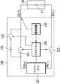
図1は一実施形態によるバッテリー装置を示す図であり、図2は一実施形態によるバッテリー装置でのスイッチングタイミングを示す図である。Figure 1 shows a battery device according to one embodiment, and Figure 2 shows the switching timing in a battery device according to one embodiment.
図1を参照すれば、バッテリー装置100は、正極連結端子DC(+)と負極連結端子DC(-)を通じて外部装置10に電気的に連結できる構造を有する。外部装置が負荷である場合、バッテリー装置100は負荷に電力を供給する電源として動作して放電される。負荷として動作する外部装置10は例えば、電子装置、移動手段またはエネルギー貯蔵システム(energy storage system、ESS)であってもよく、移動手段は例えば、電気自動車、ハイブリッド自動車またはスマートモビリティー(smart mobility)であってもよい。Referring to FIG. 1, the
バッテリー装置100は、バッテリーパック110、スイッチ回路、プリチャージ回路、感知回路140、およびプロセッサー150を含む。The
バッテリーパック110は複数のバッテリーセル(図示せず)を含み、正極端子PV(+)と負極端子PV(-)を有する。一実施形態で、バッテリーセルは、充電可能な二次電池であってもよい。一実施形態で、バッテリーパック110において所定個数のバッテリーセルが直列連結されてバッテリーモジュールを構成して所望の電力を供給することができる。他の実施形態で、バッテリーパック110において所定個数のバッテリーモジュールが直列または並列連結されて所望の電力を供給することができる。The
スイッチ回路は、バッテリーパック110の正極端子PV(+)とバッテリー装置100の正極連結端子DC(+)の間に連結されている正極メインスイッチ121およびバッテリーパック110の負極端子PV(-)とバッテリー装置100の負極連結端子DC(-)の間に連結されている負極メインスイッチ122を含む。一実施形態で、スイッチ121、122はそれぞれリレーから形成されるコンタクタであってもよい。他の実施形態で、スイッチ121、122はそれぞれトランジスタなどの電気的スイッチであってもよい。一実施形態で、スイッチ回路はスイッチ121、122をそれぞれ制御する駆動回路(図示せず)をさらに含むことができる。The switch circuit includes a positive
プリチャージ回路はバッテリーパック110の正極端子PV(+)とバッテリー装置100の正極連結端子DC(+)の間に連結されており、プリチャージ期間の間に連結端子DC(+)、DC(-)に連結される外部装置10のキャパシタ11を先に充電することができる。一実施形態で、プリチャージ回路は、プリチャージ抵抗131と、プリチャージスイッチ132を含むことができる。プリチャージスイッチ132が閉じられる場合、プリチャージ抵抗131はバッテリーパック110の正極端子PV(+)とバッテリー装置100の正極連結端子DC(+)の間に連結できる。これにより、プリチャージ回路はプリチャージ抵抗131を通じて外部装置10のキャパシタ11を先に充電することができる。一実施形態で、プリチャージ抵抗131とプリチャージスイッチ132は、バッテリーパック110の正極端子PV(+)とバッテリー装置100の正極連結端子DC(+)の間に直列に連結できる。一実施形態で、プリチャージスイッチ132は、リレーから形成されるコンタクタであってもよい。他の実施形態で、プリチャージスイッチ132は、トランジスタなどの電気的スイッチであってもよい。一実施形態で、プリチャージ回路は、プリチャージスイッチ132を制御する駆動回路(図示せず)をさらに含むことができる。The precharge circuit is connected between the positive terminal PV(+) of the
感知回路140は、バッテリー装置100で所定地点の電圧を感知する。一実施形態で、感知回路140は、バッテリー装置100の正極連結端子DC(+)の電圧を感知することができる。一実施形態で、感知回路140は、正極連結端子DC(+)と接地端子の間に直列に連結される複数の抵抗(図示せず)を含むことができる。この場合、感知回路140は、複数の抵抗によって正極連結端子DC(+)の電圧が分圧された電圧を正極連結端子DC(+)の電圧として感知することができる。一実施形態で、感知回路140は、複数の抵抗によって分圧された電圧をデジタル信号に変換してプロセッサー150に伝達するアナログデジタル変換器をさらに含むことができる。The
プロセッサー150は、スイッチ121、122、132の動作を制御することができる。また、プロセッサー150は、感知回路140に感知された電圧に基づいてプリチャージ期間を設定することができる。一実施形態で、プロセッサー150は感知回路140に感知された電圧に基づいてキャパシタ11のキャパシタンスを診断することができる。一実施形態で、プロセッサー150は例えばマイクロ制御装置(micro controller unit、MCU)であってもよい。The
一実施形態で、感知回路140とプロセッサー150はバッテリー装置のバッテリー管理システム(battery management system、BMS)に含まれる。In one embodiment, the
図2を参照すれば、バッテリー装置の初期駆動時に、プロセッサー150は負極メインスイッチ122を先に閉じる。その次に、プロセッサー150は負極メインスイッチ122を閉じた状態でプリチャージスイッチ132を閉じる。これにより、バッテリーパック110からプリチャージ抵抗131を通じて外部装置10のキャパシタ11にプリチャージ電流が供給されてキャパシタ11が充電できる。プリチャージスイッチ132を閉じてキャパシタ11を充電する期間をプリチャージ期間といえる。Referring to FIG. 2, when the battery device is initially driven, the
その次に、外部装置10のキャパシタ11を充電した後に、プロセッサー150はバッテリーパック110の電圧を外部装置10に伝達するために正極メインスイッチ121を閉じる。この場合、プリチャージが完了したので、プロセッサー150はプリチャージスイッチ132を開けることができる。したがって、外部装置10のキャパシタ11に充電された電圧によって外部装置10にバッテリーパック110の電圧を供給する時に突入電流が発生するのを防止することができる。スイッチの閉鎖はスイッチオン(on)といえ、スイッチの開放はスイッチのオフ(off)といえる。Next, after charging the
次に、多様な実施形態によるプリチャージ期間設定方法について図3~図6を参照して説明する。Next, the precharge period setting method according to various embodiments will be described with reference to Figures 3 to 6.
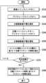
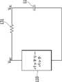
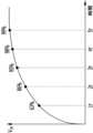
図3は一実施形態によるバッテリー装置でのプリチャージ期間設定方法の一例を示すフローチャートであり、図4は一実施形態によるバッテリー装置においてプリチャージ期間での等価回路の一例を示す図である。図5は一実施形態によるバッテリー装置において正極連結端子の電圧の一例を示す図であり、図6は時定数の倍数による電圧比率を示す図である。Figure 3 is a flow chart showing an example of a method for setting a precharge period in a battery device according to an embodiment, and Figure 4 is a diagram showing an example of an equivalent circuit during a precharge period in a battery device according to an embodiment. Figure 5 is a diagram showing an example of a voltage at a positive electrode connection terminal in a battery device according to an embodiment, and Figure 6 is a diagram showing a voltage ratio according to a multiple of a time constant.
図3を参照すれば、バッテリー装置のプロセッサー(例えば、図1の150)は負極メインスイッチ(例えば、図1の122)を閉じ(S310)、プリチャージスイッチ(例えば、図1の132)を閉じる(S320)。これにより、プリチャージ期間が開始され外部装置のキャパシタ(例えば、図1の11)が充電できる。Referring to FIG. 3, the processor of the battery device (e.g., 150 in FIG. 1) closes the negative main switch (e.g., 122 in FIG. 1) (S310) and closes the precharge switch (e.g., 132 in FIG. 1) (S320). This starts the precharge period and allows the capacitor of the external device (e.g., 11 in FIG. 1) to be charged.
プリチャージ動作を行った後に(例えば、プリチャージ期間が終了する時)、プロセッサー150は正極メインスイッチ(例えば、図1の121)を閉じる(S340)。プロセッサー150は、正極メインスイッチ121を閉じて正極連結端子DC(+)にバッテリーパック110の電圧を印加することができる。正極メインスイッチ121を閉じる直前に(例えば、正極連結端子DC(+))にバッテリーパック110の電圧を印加する直前に)、プロセッサー150は感知回路(例えば、図1の140)が感知したバッテリー装置の正極連結端子(例えば、DC(+))の電圧を測定する(S330)。また、正極メインスイッチ121を閉じた直後に(例えば、正極連結端子DC(+)にバッテリーパック110の電圧を印加した直後に)、プロセッサー150は感知回路140が感知したバッテリー装置の正極連結端子DC(+)の電圧を測定する(S350)。一実施形態で、プロセッサー150は正極メインスイッチ121を閉じた後に、プリチャージスイッチ132を開けることができる(S340)。After performing the precharge operation (e.g., when the precharge period ends), the
プロセッサー150は正極メインスイッチ121を閉じる直前に測定したバッテリー装置の正極連結端子DC(+)の電圧と正極メインスイッチ121を閉じた直後に測定したバッテリー装置の正極連結端子DC(+)の電圧に基づいてプリチャージ期間の目標時間(これから"目標プリチャージ時間"という)を推定する(S360)。一実施形態で、プロセッサー150は推定した目標プリチャージ時間を現在サイクルにおける目標プリチャージ時間として保存することができる。The
プロセッサー150は目標プリチャージ時間に基づいて次のサイクルにおけるプリチャージ期間の時間(これから"プリチャージ時間"という)を設定する(S370、S380)。一実施形態で、複数のサイクルにおける目標プリチャージ時間に基づいて次のサイクルにおけるプリチャージ時間を設定することができる。このために、プロセッサー150は所定回数のサイクルにおける目標プリチャージ時間がそれぞれ推定されたかを判断することができる(S370)。所定回数のサイクルにおける目標プリチャージ時間が推定されていない場合(S370)、プロセッサー150は次のサイクルが開始される時、S310からの過程を繰り返すことができる。所定回数のサイクルにおける目標プリチャージ時間が推定された場合(S370)、プロセッサー150は所定回数のサイクルにおいて推定された目標プリチャージ時間に基づいて次のサイクルにおけるプリチャージ時間を設定することができる(S380)。一実施形態で、プロセッサー150は所定回数のサイクルにおいて推定された目標プリチャージ時間のうちの最大値を次のサイクルにおけるプリチャージ時間に設定することができる(S380)。一実施形態で、所定回数は5回であってもよい。The
一方、図4に示したように、プリチャージスイッチ132を閉じると、バッテリーパック110、プリチャージ抵抗131、およびキャパシタ11によって形成されるRC等価回路が形成できる。そうすると、キャパシタ11の電圧、即ち、正極連結端子DC(+)の電圧VDCはRC等価回路410の時定数τに基づいて図5に示したように増加する。キャパシタ11の電圧VDCは例えば(数1)式のように変動できる。 On the other hand, as shown in Fig. 4, when the

(数1)式中、時定数τはプリチャージ抵抗131の抵抗値RPとキャパシタ11のキャパシタンスCEXの積と定義される。 In equation (1), the time constant τ is defined as the product of the resistance RP of the
図5に示したように、正極メインスイッチ121を閉じた直後に、正極連結端子DC(+)の電圧はバッテリーパック110の電圧VBATに変更される。正極メインスイッチ121を閉じた直後に測定した正極連結端子DC(+)の電圧はバッテリーパック110の電圧VBATに該当する。したがって、プロセッサー150は、正極メインスイッチ121を閉じる直前の正極連結端子DC(+)の電圧VDC(プリチャージ期間の終了時のキャパシタ11の電圧)と正極メインスイッチ121を閉じた直後の正極連結端子DC(+)の電圧VBAT(バッテリーパック110の電圧)に基づいて時定数を推定することができる。例えば、(数1)式でVDCを正極メインスイッチ121を閉じる直前の正極連結端子DC(+)の電圧に、VBATを正極メインスイッチ121を閉じた直後の正極連結端子DC(+)の電圧に、tを現在サイクルにおけるプリチャージ期間の時間に設定して、時定数τが計算できる。 5, immediately after the positive
したがって、プロセッサー150は、時定数τに基づいて目標プリチャージ時間を設定することができる。一実施形態で、プロセッサー150は、時定数のn倍を目標プリチャージ時間に設定することができる(nは正の実数)。図6に示したように、図4に示した等価回路で、時定数の1倍(τ)でのキャパシタ11の電圧VDCはバッテリーパック110の電圧VBATの63%に該当し、時定数の2倍(2τ)でのキャパシタ11の電圧VDCはバッテリーパック110の電圧VBATの86%に該当し、時定数の3倍(3τ)でのキャパシタ11の電圧VDCはバッテリーパック110の電圧VBATの95%に該当し、時定数の4倍(4τ)でのキャパシタ11の電圧VDCはバッテリーパック110の電圧VBATの98%に該当し、時定数の5倍(5τ)でのキャパシタ11の電圧VDCはバッテリーパック110の電圧VBATの99%に該当する。例えば、プロセッサー150は、キャパシタ11の電圧VDCはバッテリーパック110の電圧VBATの99%になる時定数の5倍(5τ)を目標プリチャージ時間に設定することができる。時定数の5倍(5τ)を目標プリチャージ時間に設定する場合、正極連結端子DC(+)の電圧VDCがバッテリーパック110の電圧VBATの99%に到達する時に正極メインスイッチ121が閉じられるので、正極メインスイッチ121の損傷が最少化できる。また、一実施形態で、複数のサイクルの目標プリチャージ時間のうちの最大値が選択される場合、複数のサイクルにおける測定偏差を考慮して正極メインスイッチ121の損傷が最少化できる時間が選択できる。 Therefore, the
以上で説明した実施形態によれば、所定回数のサイクルにおいて推定した目標プリチャージ時間に基づいてプリチャージ時間に設定することによって、正確なプリチャージ時間を設定することができる。この場合、キャパシタのキャパシタンスが変わってもプリチャージ時間が適応的に設定できる。また、正極メインスイッチ121を閉じる直前と正極メインスイッチ121を閉じた直後に正極連結端子DC(+)の電圧を測定するため、二つの電圧測定時点の差を最少化することができる。即ち、二回の電圧測定が実質的に同一な環境で行われるので、電圧測定に関連する素子の誤差を最少化し、これにより、時定数が正確に推定できる。According to the embodiment described above, the precharge time can be set accurately by setting it based on the target precharge time estimated in a predetermined number of cycles. In this case, the precharge time can be adaptively set even if the capacitance of the capacitor changes. In addition, since the voltage of the positive electrode connection terminal DC(+) is measured immediately before closing the positive electrode
前述のように、プロセッサー150は、所定回数のサイクルにおいてそれぞれ推定された目標プリチャージ時間に基づいて次のサイクルにおいてプリチャージ時間を設定することができる。したがって、現在サイクルにおけるプリチャージ時間は、所定回数の以前サイクルにおいてそれぞれ推定された目標プリチャージ時間に基づいて設定できる。例えば、i番目サイクルにおけるプリチャージ時間は、(i-5)番目から(i-1)番目サイクルにおいてそれぞれ推定された目標プリチャージ時間に基づいて設定できる。一方、現在サイクルにおけるプリチャージ時間を設定するのに必要な所定回数の以前サイクルにおける目標プリチャージ時間が保存されていない場合が存在することがある。例えば、最初サイクルにおいては以前サイクルが行われなかったので、以前サイクルにおける目標プリチャージ時間が存在しないことがある。また、二番目から五番目サイクルにおいても所定回数の以前サイクルが行われなかったので、所定回数の以前サイクルにおける目標プリチャージ時間が存在しないことがある。この場合、現在サイクルにおけるプリチャージ時間が設定されないことがある。As described above, the
以下では、現在サイクルにおけるプリチャージ時間が設定されていない場合、プリチャージ時間を設定する実施形態について図7を参照して説明する。Below, an embodiment for setting the precharge time when the precharge time for the current cycle has not been set will be described with reference to FIG. 7.
図7は、他の実施形態によるバッテリー装置においてプリチャージ時間の初期値を設定する方法の一例を示すフローチャートである。Figure 7 is a flowchart showing an example of a method for setting an initial value of the precharge time in a battery device according to another embodiment.
図7を参照すれば、バッテリー装置のプロセッサー(例えば、図1の150)は負極メインスイッチ(例えば、図1の122)を閉じ(S710)、プリチャージスイッチ(例えば、図1の132)を閉じる(S720)。これにより、プリチャージ期間が開始され外部装置のキャパシタ(例えば、図1の11)が充電される。一実施形態で、プロセッサー150は、プリチャージ期間が開始される時にタイマーを稼動してプリチャージ期間の経過時間を測定することができる。例えば、プロセッサー150は、プリチャージスイッチ132を閉じる時点からタイマーを稼動することができる。Referring to FIG. 7, the processor (e.g., 150 in FIG. 1) of the battery device closes the negative main switch (e.g., 122 in FIG. 1) (S710) and closes the pre-charge switch (e.g., 132 in FIG. 1) (S720). This starts the pre-charge period and charges the capacitor (e.g., 11 in FIG. 1) of the external device. In one embodiment, the
プロセッサー150は、現在サイクルにおけるプリチャージ時間が設定されているかを判断する(S730)。一実施形態で、プロセッサー150は、所定回数の以前サイクルにおける目標プリチャージ時間に基づいて現在サイクルにおけるプリチャージ時間が設定されたかを判断することができる(S730)。一実施形態で、プロセッサー150は、目標プリチャージ時間が推定された以前サイクルの数と所定回数を比較することができる(S730)。The
現在サイクルにおけるプリチャージ時間が設定されていない場合(S730)、プロセッサー150は感知回路(例えば、図1の140)を通じてバッテリー装置の正極連結端子(例えば、DC(+))の電圧VDCをモニタリングする(S740)。プロセッサー150は、正極連結端子DC(+)の電圧VDCをモニタリングしながら、正極連結端子DC(+)の電圧と所定電圧を比較する(S750)。所定電圧は、バッテリーパック(例えば、図1の110)の電圧VBATに基づいて決定された電圧である。一実施形態で、感知回路140がバッテリーパック110の正極端子PV(+)の電圧を感知してプロセッサー150がバッテリーパック110の電圧VBATを測定することができる。一実施形態で、所定電圧は、バッテリーパック110の電圧VBATと時定数のm倍に基づいて設定できる(mは正の実数)。一実施形態で、バッテリーパック110の電圧VBATに対する所定電圧の比率が図4に示した等価回路において時定数のm倍に該当するプリチャージ時間が経過した後のバッテリーパック110の電圧VBATに対するキャパシタ11の電圧の比率になるように所定電圧が設定できる。例えば、時定数の2倍に基づいて所定電圧がバッテリーパック110の電圧VBATの86%、即ち、0.86VBATに設定できる。 If the precharge time in the current cycle is not set (S730), the
正極連結端子DC(+)の電圧が所定電圧に到達する場合(S750)、プロセッサー150は、正極連結端子DC(+)の電圧が所定電圧に到達するのにかかった時間に基づいて現在サイクルにおけるプリチャージ時間(初期プリチャージ時間)を設定する(S760)。一実施形態で、プロセッサー150は、バッテリーパック110の電圧VBATが所定電圧に到達するのにかかった時間と所定電圧の設定に使用される時定数のm倍に基づいて初期プリチャージ時間を設定することができる(S760)。一実施形態で、プロセッサー150は、バッテリーパック110の電圧VBATが所定電圧に到達するのにかかった時間のk倍を初期プリチャージ時間に設定することができる(kは正の実数)。この場合、初期プリチャージ時間は時定数の(k*m)倍に設定できる。一実施形態で、(k*m)は、前述の目標プリチャージ時間の設定に使用される時定数の倍数(n)より大きく設定できる。例えば、目標プリチャージ時間が時定数の5倍に設定され(n=5)、所定電圧が時定数の2倍に基づいて設定される(m=2)場合、初期プリチャージ時間は時定数の6倍に設定できる(k=3)。このように、初期プリチャージ時間を長く設定することによって、電圧測定誤差による正極メインスイッチ(例えば、図1の121)の損傷を最少化することができる。 When the voltage of the positive connection terminal DC(+) reaches a predetermined voltage (S750), the
初期プリチャージ時間を設定した場合(S760)、プリチャージ期間が開始された時点からS760で設定した初期プリチャージ時間が経過した後に、プロセッサー150は正極メインスイッチ121を閉じる(S770)。プリチャージ時間が既に設定されている場合(S730)、プリチャージ期間が開始された時点から設定されたプリチャージ時間が経過した後に、プロセッサー150は正極メインスイッチ121を閉じる(S770)。これにより、プリチャージ期間が終了する。一実施形態で、プロセッサー150は正極メインスイッチ121を閉じた後に、プリチャージスイッチ132を開けることができる(S770)。If an initial precharge time is set (S760), the
一実施形態で、プロセッサー150は、図3を参照して説明したように正極メインスイッチ121を閉じる直前にバッテリー装置の正極連結端子DC(+)の電圧を測定し、正極メインスイッチ121を閉じた直後にバッテリー装置の正極連結端子DC(+)の電圧を測定することができる。プロセッサー150は、正極メインスイッチ121を閉じる直前に測定したバッテリー装置の正極連結端子DC(+)の電圧と正極メインスイッチ121を閉じた直後に測定したバッテリー装置の正極連結端子DC(+)の電圧に基づいて現在サイクルにおける目標プリチャージ時間を推定することができる。In one embodiment, the
以上で説明したように、以前サイクルにおける目標プリチャージ時間が推定されていない場合に初期プリチャージ時間を設定することができる。As explained above, an initial precharge time can be set if the target precharge time in the previous cycle has not been estimated.
以上で本発明の実施形態について詳細に説明したが、本発明の権利範囲はこれに限定されるのではなく、次の特許請求の範囲で定義している本発明の基本概念を用いた当業者の様々な変形および改良形態も本発明の権利範囲に属するのである。Although the embodiments of the present invention have been described in detail above, the scope of the present invention is not limited thereto, and various modifications and improvements made by those skilled in the art using the basic concept of the present invention defined in the following claims also fall within the scope of the present invention.
Claims (21)
Translated fromJapaneseバッテリーパックと、
前記バッテリーパックの正極端子と前記正極連結端子の間に連結される正極メインスイッチと、
前記バッテリーパックの正極端子と前記正極連結端子の間に連結され、前記外部装置のキャパシタのプリチャージ動作を制御するプリチャージスイッチと、
複数のサイクルそれぞれにおいてプリチャージ期間の目標時間を推定し、前記複数のサイクルにおいてそれぞれ推定された前記目標時間に基づいて前記複数のサイクルの次のサイクルにおけるプリチャージ期間の時間を設定するプロセッサーと
を含むバッテリー装置。 A battery device having a positive electrode connection terminal and a negative electrode connection terminal connected to an external device,
A battery pack;
a positive main switch connected between the positive terminal of the battery pack and the positive connection terminal;
a pre-charge switch connected between the positive terminal of the battery pack and the positive connecting terminal to control a pre-charge operation of a capacitor of the external device;
A battery device comprising: a processor that estimates a target time for a precharge period in each of a plurality of cycles, and sets a time for a precharge period in a next cycle of the plurality of cycles based on the target time estimated for each of the plurality of cycles.
前記プリチャージ期間の間に前記プリチャージスイッチを閉じてプリチャージを行い、
前記プリチャージ期間以後に前記正極メインスイッチを閉じ、
前記正極メインスイッチを閉じる直前の前記正極連結端子の第1電圧と前記正極メインスイッチを閉じた直後の前記正極連結端子の第2電圧に基づいて前記目標時間を推定する
請求項1または2に記載のバッテリー装置。 The processor, in each cycle:
During the precharge period, the precharge switch is closed to perform precharge;
After the precharge period, the positive main switch is closed;
The battery device according to claim 1 or 2, wherein the target time is estimated based on a first voltage of the positive connecting terminal immediately before the positive main switch is closed and a second voltage of the positive connecting terminal immediately after the positive main switch is closed.
前記第1電圧と前記第2電圧に基づいて前記プリチャージ抵抗の抵抗値と前記キャパシタのキャパシタンスによって定義される時定数を推定し、
前記時定数の所定倍数を前記目標時間と推定する
請求項4に記載のバッテリー装置。 the processor estimates a time constant defined by a resistance value of the pre-charge resistor and a capacitance of the capacitor based on the first voltage and the second voltage;
The battery device according to claim 4 , wherein a predetermined multiple of the time constant is estimated as the target time.
複数のサイクルそれぞれのプリチャージ期間でプリチャージ抵抗を通じて前記正極連結端子と前記負極連結端子に連結されるキャパシタをプリチャージするプリチャージ動作を行う段階と、
前記複数のサイクルそれぞれにおいて前記プリチャージ期間の目標時間を推定する段階と、
前記複数のサイクルにおいてそれぞれ推定された前記目標時間に基づいて前記複数のサイクルの次のサイクルにおけるプリチャージ期間の時間を設定する段階と
を含むプリチャージ期間設定方法。 A method for setting a pre-charge period of a battery device including a positive electrode connecting terminal and a negative electrode connecting terminal connected to a battery pack and an external device, comprising:
performing a precharge operation of precharging a capacitor connected to the positive electrode connecting terminal and the negative electrode connecting terminal through a precharge resistor during a precharge period of each of a plurality of cycles;
estimating a target time for the precharge period in each of the plurality of cycles;
setting a precharge period in a cycle next to the plurality of cycles based on the target time estimated in each of the plurality of cycles.
前記プリチャージ動作を行った後に、前記正極連結端子に前記バッテリーパックの電圧を印加する段階と、
前記バッテリーパックの電圧を印加する直前に前記正極連結端子の電圧を第1電圧として測定する段階と、
前記バッテリーパックの電圧を印加した直後に前記正極連結端子の電圧を第2電圧として測定する段階と、
前記第1電圧および前記第2電圧に基づいて前記目標時間を推定する段階と
を含む、請求項14または15に記載のプリチャージ期間設定方法。 The step of estimating the target time includes:
applying a voltage of the battery pack to the positive electrode connecting terminal after performing the precharge operation;
measuring a voltage of the positive electrode connecting terminal as a first voltage immediately before applying a voltage to the battery pack;
measuring a voltage of the positive electrode connecting terminal as a second voltage immediately after applying a voltage to the battery pack;
estimating the target time based on the first voltage and the secondvoltage .
前記第1電圧と前記第2電圧に基づいて前記プリチャージ抵抗の抵抗値と前記キャパシタのキャパシタンスによって定義される時定数を推定する段階と、
前記時定数の所定倍数を前記目標時間と推定する段階と
を含む、請求項16に記載のプリチャージ期間設定方法。 The step of estimating the target time based on the first voltage and the second voltage includes:
estimating a time constant defined by a resistance value of the pre-charge resistor and a capacitance of the capacitor based on the first voltage and the second voltage;
17. The precharge period setting method according to claim16 , further comprising: estimating a predetermined multiple of the time constant as the target time.
前記バッテリーパックの正極端子と前記正極連結端子の間に連結される正極メインスイッチと、
前記バッテリーパックの正極端子と前記正極連結端子の間に連結され、前記外部装置のキャパシタのプリチャージ動作を制御するプリチャージスイッチと、
複数のサイクルそれぞれにおいてプリチャージ期間の目標時間を推定し、前記複数のサイクルにおいてそれぞれ推定された前記目標時間に基づいて前記複数のサイクルの次のサイクルにおけるプリチャージ期間の時間を設定するプロセッサーと
を含むバッテリー管理システム。 A battery management system for a battery device including a battery pack and a positive connection terminal and a negative connection terminal connected to an external device,
a positive main switch connected between the positive terminal of the battery pack and the positive connection terminal;
a pre-charge switch connected between the positive terminal of the battery pack and the positive connecting terminal to control a pre-charge operation of a capacitor of the external device;
a processor that estimates a target time for a pre-charge period in each of a plurality of cycles, and sets a time for a pre-charge period in a next cycle of the plurality of cycles based on the target time estimated for each of the plurality of cycles.
Applications Claiming Priority (3)
| Application Number | Priority Date | Filing Date | Title |
|---|---|---|---|
| KR1020210147896AKR20230063056A (en) | 2021-11-01 | 2021-11-01 | Battery apparatus, battery management system, and method for setting precharge period |
| KR10-2021-0147896 | 2021-11-01 | ||
| PCT/KR2022/014260WO2023075164A1 (en) | 2021-11-01 | 2022-09-23 | Battery device, battery management system, and pre-charge period configuration method |
Publications (2)
| Publication Number | Publication Date |
|---|---|
| JP2023551119A JP2023551119A (en) | 2023-12-07 |
| JP7574994B2true JP7574994B2 (en) | 2024-10-29 |
Family
ID=86158299
Family Applications (1)
| Application Number | Title | Priority Date | Filing Date |
|---|---|---|---|
| JP2023527823AActiveJP7574994B2 (en) | 2021-11-01 | 2022-09-23 | Battery device, battery management system, and precharge period setting method |
Country Status (6)
| Country | Link |
|---|---|
| US (1) | US20250183681A1 (en) |
| EP (1) | EP4404426A4 (en) |
| JP (1) | JP7574994B2 (en) |
| KR (1) | KR20230063056A (en) |
| CN (1) | CN118140379A (en) |
| WO (1) | WO2023075164A1 (en) |
Families Citing this family (1)
| Publication number | Priority date | Publication date | Assignee | Title |
|---|---|---|---|---|
| WO2025048276A1 (en)* | 2023-08-31 | 2025-03-06 | 주식회사 엘지에너지솔루션 | Resistor unit, resistor assembly, and battery pack |
Citations (5)
| Publication number | Priority date | Publication date | Assignee | Title |
|---|---|---|---|---|
| JP2008005658A (en) | 2006-06-23 | 2008-01-10 | Toyota Motor Corp | Vehicle power supply device and vehicle equipped with the same |
| JP2009532845A (en) | 2006-04-04 | 2009-09-10 | タイコ・エレクトロニクス・コーポレイション | Semiconductor precharge module |
| JP2013205257A (en) | 2012-03-28 | 2013-10-07 | Sanyo Electric Co Ltd | Power supply device, and vehicle and power storage device equipped with power supply device |
| CN106100059A (en) | 2016-07-29 | 2016-11-09 | 观致汽车有限公司 | The control method of pre-charge circuit, battery management system and vehicle |
| KR20210107415A (en) | 2020-02-24 | 2021-09-01 | 엘에스일렉트릭(주) | Apparatus and method for diagnosing initial charging circuit of inverter |
Family Cites Families (7)
| Publication number | Priority date | Publication date | Assignee | Title |
|---|---|---|---|---|
| KR100867834B1 (en)* | 2007-08-16 | 2008-11-10 | 현대자동차주식회사 | Fault diagnosis method of high voltage relay and relay control circuit of hybrid vehicle |
| KR20090039891A (en)* | 2007-10-19 | 2009-04-23 | 현대자동차주식회사 | Hybrid vehicle precharging control method |
| JP4821906B2 (en)* | 2009-11-27 | 2011-11-24 | 株式会社豊田自動織機 | Power control device |
| KR102663546B1 (en)* | 2016-12-13 | 2024-05-08 | 현대자동차주식회사 | Pre-charge method and system for high voltage link capacitor of vehicle |
| JP7103199B2 (en)* | 2018-12-17 | 2022-07-20 | 株式会社デンソー | Precharge controller |
| JP7013411B2 (en)* | 2019-04-10 | 2022-01-31 | プライムアースEvエナジー株式会社 | Rechargeable battery system |
| JP7197441B2 (en)* | 2019-07-31 | 2022-12-27 | 株式会社ミツバ | Power supply device, power supply method, and power supply program |
- 2021
- 2021-11-01KRKR1020210147896Apatent/KR20230063056A/enactivePending
- 2022
- 2022-09-23EPEP22887368.3Apatent/EP4404426A4/enactivePending
- 2022-09-23WOPCT/KR2022/014260patent/WO2023075164A1/ennot_activeCeased
- 2022-09-23USUS18/701,435patent/US20250183681A1/enactivePending
- 2022-09-23JPJP2023527823Apatent/JP7574994B2/enactiveActive
- 2022-09-23CNCN202280070291.4Apatent/CN118140379A/enactivePending
Patent Citations (5)
| Publication number | Priority date | Publication date | Assignee | Title |
|---|---|---|---|---|
| JP2009532845A (en) | 2006-04-04 | 2009-09-10 | タイコ・エレクトロニクス・コーポレイション | Semiconductor precharge module |
| JP2008005658A (en) | 2006-06-23 | 2008-01-10 | Toyota Motor Corp | Vehicle power supply device and vehicle equipped with the same |
| JP2013205257A (en) | 2012-03-28 | 2013-10-07 | Sanyo Electric Co Ltd | Power supply device, and vehicle and power storage device equipped with power supply device |
| CN106100059A (en) | 2016-07-29 | 2016-11-09 | 观致汽车有限公司 | The control method of pre-charge circuit, battery management system and vehicle |
| KR20210107415A (en) | 2020-02-24 | 2021-09-01 | 엘에스일렉트릭(주) | Apparatus and method for diagnosing initial charging circuit of inverter |
Also Published As
| Publication number | Publication date |
|---|---|
| US20250183681A1 (en) | 2025-06-05 |
| KR20230063056A (en) | 2023-05-09 |
| CN118140379A (en) | 2024-06-04 |
| EP4404426A4 (en) | 2025-01-15 |
| EP4404426A1 (en) | 2024-07-24 |
| WO2023075164A1 (en) | 2023-05-04 |
| JP2023551119A (en) | 2023-12-07 |
Similar Documents
| Publication | Publication Date | Title |
|---|---|---|
| US12074465B2 (en) | Control device, electric storage device, electric storage system, and computer-readable medium | |
| JP5812032B2 (en) | Power storage system and method for estimating full charge capacity of power storage device | |
| JP6197479B2 (en) | Power storage system and method for estimating full charge capacity of power storage device | |
| CN102341715B (en) | Method and apparatus for detecting abnormality of current sensor in battery pack | |
| US20130021000A1 (en) | Charge and discharge control apparatus | |
| US8174242B2 (en) | Apparatus and method for pre-charging in charging/discharging equipment for an energy-storage device | |
| US9625531B2 (en) | Apparatus and method for calculating precharge resistance of battery pack | |
| CN106133994A (en) | Secondary battery state detection device and secondary battery state detection method | |
| US20140184236A1 (en) | Battery control apparatus and battery system | |
| JP6412847B2 (en) | Power storage device and control method | |
| WO2015199178A1 (en) | Balance correction control device, balance correction system, and power storage system | |
| CN111527644A (en) | Rechargeable battery abnormality detection device and rechargeable battery abnormality detection method | |
| KR101567557B1 (en) | Voltage balancing apparatus and method of secondary battery cells | |
| JP7574994B2 (en) | Battery device, battery management system, and precharge period setting method | |
| JP7513364B2 (en) | Battery device, battery management system, and diagnostic method | |
| JPH11355966A (en) | Battery charging and discharging devices | |
| JP7732656B2 (en) | Battery equipment and battery management systems for insulation resistance measurements | |
| JP4986806B2 (en) | Charging apparatus and charging method | |
| JP6434245B2 (en) | Charging rate estimation device and power supply system | |
| JP6953323B2 (en) | Rechargeable battery status detector and rechargeable battery status detection method | |
| Becherif et al. | Enhancement of the coulomb counter estimator by the on-board vehicle determination of battery initial state of charge | |
| KR20160071929A (en) | Battery management system | |
| KR102823245B1 (en) | Battery apparatus, battery management system, and diagnosis method | |
| KR20220036555A (en) | Battery apparatus, battery management system, and method of measuring precharge current | |
| JP2015042013A (en) | Charging device |
Legal Events
| Date | Code | Title | Description |
|---|---|---|---|
| A621 | Written request for application examination | Free format text:JAPANESE INTERMEDIATE CODE: A621 Effective date:20230517 | |
| A977 | Report on retrieval | Free format text:JAPANESE INTERMEDIATE CODE: A971007 Effective date:20240423 | |
| A131 | Notification of reasons for refusal | Free format text:JAPANESE INTERMEDIATE CODE: A131 Effective date:20240528 | |
| A521 | Request for written amendment filed | Free format text:JAPANESE INTERMEDIATE CODE: A523 Effective date:20240729 | |
| TRDD | Decision of grant or rejection written | ||
| A01 | Written decision to grant a patent or to grant a registration (utility model) | Free format text:JAPANESE INTERMEDIATE CODE: A01 Effective date:20240917 | |
| A61 | First payment of annual fees (during grant procedure) | Free format text:JAPANESE INTERMEDIATE CODE: A61 Effective date:20241007 | |
| R150 | Certificate of patent or registration of utility model | Ref document number:7574994 Country of ref document:JP Free format text:JAPANESE INTERMEDIATE CODE: R150 |