JP7574349B2 - System for controlling control circuitry for independently delivering energy across segmented sections - Patents.com - Google Patents
System for controlling control circuitry for independently delivering energy across segmented sections - Patents.comDownload PDFInfo
- Publication number
- JP7574349B2 JP7574349B2JP2023032649AJP2023032649AJP7574349B2JP 7574349 B2JP7574349 B2JP 7574349B2JP 2023032649 AJP2023032649 AJP 2023032649AJP 2023032649 AJP2023032649 AJP 2023032649AJP 7574349 B2JP7574349 B2JP 7574349B2
- Authority
- JP
- Japan
- Prior art keywords
- end effector
- tissue
- conductor
- electrodes
- electrode
- Prior art date
- Legal status (The legal status is an assumption and is not a legal conclusion. Google has not performed a legal analysis and makes no representation as to the accuracy of the status listed.)
- Active
Links
- 239000012636effectorSubstances0.000claimsdescription146
- 239000004020conductorSubstances0.000claimsdescription140
- 230000015271coagulationEffects0.000claimsdescription7
- 238000005345coagulationMethods0.000claimsdescription7
- 210000001519tissueAnatomy0.000description210
- 238000010304firingMethods0.000description71
- 230000033001locomotionEffects0.000description38
- 238000000034methodMethods0.000description27
- 238000007726management methodMethods0.000description25
- 238000004891communicationMethods0.000description21
- 238000010586diagramMethods0.000description18
- 230000006870functionEffects0.000description15
- 230000004927fusionEffects0.000description14
- 230000008569processEffects0.000description14
- 238000006073displacement reactionMethods0.000description6
- 230000005355Hall effectEffects0.000description5
- 238000003466weldingMethods0.000description5
- 230000001133accelerationEffects0.000description4
- 230000005540biological transmissionEffects0.000description4
- 210000004204blood vesselAnatomy0.000description4
- 230000008859changeEffects0.000description4
- 230000006835compressionEffects0.000description4
- 238000007906compressionMethods0.000description4
- 238000010168coupling processMethods0.000description4
- 230000007423decreaseEffects0.000description4
- 230000003247decreasing effectEffects0.000description4
- 230000007246mechanismEffects0.000description4
- 238000007789sealingMethods0.000description4
- 238000001356surgical procedureMethods0.000description4
- 238000013519translationMethods0.000description4
- 102000008186CollagenHuman genes0.000description3
- 108010035532CollagenProteins0.000description3
- 210000003484anatomyAnatomy0.000description3
- 230000000712assemblyEffects0.000description3
- 238000000429assemblyMethods0.000description3
- 229920001436collagenPolymers0.000description3
- 238000004590computer programMethods0.000description3
- 230000008878couplingEffects0.000description3
- 238000005859coupling reactionMethods0.000description3
- 230000000694effectsEffects0.000description3
- 230000003993interactionEffects0.000description3
- 230000036961partial effectEffects0.000description3
- 102000004169proteins and genesHuman genes0.000description3
- 108090000623proteins and genesProteins0.000description3
- 230000000007visual effectEffects0.000description3
- 229920000106Liquid crystal polymerPolymers0.000description2
- 239000004977Liquid-crystal polymers (LCPs)Substances0.000description2
- HBBGRARXTFLTSG-UHFFFAOYSA-NLithium ionChemical compound[Li+]HBBGRARXTFLTSG-UHFFFAOYSA-N0.000description2
- 238000013019agitationMethods0.000description2
- 238000005452bendingMethods0.000description2
- 210000002808connective tissueAnatomy0.000description2
- 238000001035dryingMethods0.000description2
- 230000005669field effectEffects0.000description2
- 238000010438heat treatmentMethods0.000description2
- 230000002439hemostatic effectEffects0.000description2
- 239000012212insulatorSubstances0.000description2
- 229910001416lithium ionInorganic materials0.000description2
- 230000013011matingEffects0.000description2
- 229910052751metalInorganic materials0.000description2
- 239000002184metalSubstances0.000description2
- 229910044991metal oxideInorganic materials0.000description2
- 150000004706metal oxidesChemical class0.000description2
- 238000012986modificationMethods0.000description2
- 230000004048modificationEffects0.000description2
- 239000000615nonconductorSubstances0.000description2
- 230000003287optical effectEffects0.000description2
- 238000013021overheatingMethods0.000description2
- 238000012545processingMethods0.000description2
- 230000002829reductive effectEffects0.000description2
- 230000004044responseEffects0.000description2
- 230000002441reversible effectEffects0.000description2
- 239000004065semiconductorSubstances0.000description2
- 238000007493shaping processMethods0.000description2
- 210000004872soft tissueAnatomy0.000description2
- 230000000638stimulationEffects0.000description2
- 230000001360synchronised effectEffects0.000description2
- XLYOFNOQVPJJNP-UHFFFAOYSA-NwaterSubstancesOXLYOFNOQVPJJNP-UHFFFAOYSA-N0.000description2
- 238000004804windingMethods0.000description2
- 229910000497AmalgamInorganic materials0.000description1
- 230000003044adaptive effectEffects0.000description1
- 239000000853adhesiveSubstances0.000description1
- 230000001070adhesive effectEffects0.000description1
- 238000004458analytical methodMethods0.000description1
- 238000003491arrayMethods0.000description1
- 230000015572biosynthetic processEffects0.000description1
- 230000000740bleeding effectEffects0.000description1
- 239000008280bloodSubstances0.000description1
- 210000004369bloodAnatomy0.000description1
- 210000001124body fluidAnatomy0.000description1
- 239000003795chemical substances by applicationSubstances0.000description1
- 230000001112coagulating effectEffects0.000description1
- 238000010276constructionMethods0.000description1
- 230000007812deficiencyEffects0.000description1
- 230000001934delayEffects0.000description1
- 230000000994depressogenic effectEffects0.000description1
- 230000009977dual effectEffects0.000description1
- 230000002828effect on organs or tissueEffects0.000description1
- 239000012777electrically insulating materialSubstances0.000description1
- 238000012976endoscopic surgical procedureMethods0.000description1
- 229920003247engineering thermoplasticPolymers0.000description1
- 239000000835fiberSubstances0.000description1
- 239000012530fluidSubstances0.000description1
- 238000005755formation reactionMethods0.000description1
- 230000023597hemostasisEffects0.000description1
- 230000001939inductive effectEffects0.000description1
- 238000009434installationMethods0.000description1
- 230000001788irregularEffects0.000description1
- 238000012830laparoscopic surgical procedureMethods0.000description1
- 230000000670limiting effectEffects0.000description1
- 239000004973liquid crystal related substanceSubstances0.000description1
- 239000000463materialSubstances0.000description1
- 238000005259measurementMethods0.000description1
- 239000007769metal materialSubstances0.000description1
- 239000000203mixtureSubstances0.000description1
- 210000003205muscleAnatomy0.000description1
- 210000005036nerveAnatomy0.000description1
- 230000002232neuromuscularEffects0.000description1
- 238000002355open surgical procedureMethods0.000description1
- 230000008520organizationEffects0.000description1
- 230000000717retained effectEffects0.000description1
- 238000012502risk assessmentMethods0.000description1
- 230000001953sensory effectEffects0.000description1
- 230000007704transitionEffects0.000description1
- 230000029663wound healingEffects0.000description1
Images


Classifications
- A—HUMAN NECESSITIES
- A61—MEDICAL OR VETERINARY SCIENCE; HYGIENE
- A61B—DIAGNOSIS; SURGERY; IDENTIFICATION
- A61B18/00—Surgical instruments, devices or methods for transferring non-mechanical forms of energy to or from the body
- A61B18/04—Surgical instruments, devices or methods for transferring non-mechanical forms of energy to or from the body by heating
- A61B18/12—Surgical instruments, devices or methods for transferring non-mechanical forms of energy to or from the body by heating by passing a current through the tissue to be heated, e.g. high-frequency current
- A61B18/14—Probes or electrodes therefor
- A61B18/1442—Probes having pivoting end effectors, e.g. forceps
- A61B18/1445—Probes having pivoting end effectors, e.g. forceps at the distal end of a shaft, e.g. forceps or scissors at the end of a rigid rod
- A—HUMAN NECESSITIES
- A61—MEDICAL OR VETERINARY SCIENCE; HYGIENE
- A61B—DIAGNOSIS; SURGERY; IDENTIFICATION
- A61B17/00—Surgical instruments, devices or methods
- A61B17/068—Surgical staplers, e.g. containing multiple staples or clamps
- A61B17/072—Surgical staplers, e.g. containing multiple staples or clamps for applying a row of staples in a single action, e.g. the staples being applied simultaneously
- A61B17/07207—Surgical staplers, e.g. containing multiple staples or clamps for applying a row of staples in a single action, e.g. the staples being applied simultaneously the staples being applied sequentially
- A—HUMAN NECESSITIES
- A61—MEDICAL OR VETERINARY SCIENCE; HYGIENE
- A61B—DIAGNOSIS; SURGERY; IDENTIFICATION
- A61B18/00—Surgical instruments, devices or methods for transferring non-mechanical forms of energy to or from the body
- A61B18/04—Surgical instruments, devices or methods for transferring non-mechanical forms of energy to or from the body by heating
- A61B18/12—Surgical instruments, devices or methods for transferring non-mechanical forms of energy to or from the body by heating by passing a current through the tissue to be heated, e.g. high-frequency current
- A61B18/1206—Generators therefor
- A—HUMAN NECESSITIES
- A61—MEDICAL OR VETERINARY SCIENCE; HYGIENE
- A61B—DIAGNOSIS; SURGERY; IDENTIFICATION
- A61B17/00—Surgical instruments, devices or methods
- A61B17/28—Surgical forceps
- A61B17/29—Forceps for use in minimally invasive surgery
- A61B17/295—Forceps for use in minimally invasive surgery combined with cutting implements
- A—HUMAN NECESSITIES
- A61—MEDICAL OR VETERINARY SCIENCE; HYGIENE
- A61B—DIAGNOSIS; SURGERY; IDENTIFICATION
- A61B17/00—Surgical instruments, devices or methods
- A61B2017/00017—Electrical control of surgical instruments
- A—HUMAN NECESSITIES
- A61—MEDICAL OR VETERINARY SCIENCE; HYGIENE
- A61B—DIAGNOSIS; SURGERY; IDENTIFICATION
- A61B17/00—Surgical instruments, devices or methods
- A61B2017/00017—Electrical control of surgical instruments
- A61B2017/00022—Sensing or detecting at the treatment site
- A61B2017/00026—Conductivity or impedance, e.g. of tissue
- A—HUMAN NECESSITIES
- A61—MEDICAL OR VETERINARY SCIENCE; HYGIENE
- A61B—DIAGNOSIS; SURGERY; IDENTIFICATION
- A61B17/00—Surgical instruments, devices or methods
- A61B2017/00017—Electrical control of surgical instruments
- A61B2017/00022—Sensing or detecting at the treatment site
- A61B2017/00075—Motion
- A—HUMAN NECESSITIES
- A61—MEDICAL OR VETERINARY SCIENCE; HYGIENE
- A61B—DIAGNOSIS; SURGERY; IDENTIFICATION
- A61B17/00—Surgical instruments, devices or methods
- A61B2017/00017—Electrical control of surgical instruments
- A61B2017/00115—Electrical control of surgical instruments with audible or visual output
- A61B2017/00119—Electrical control of surgical instruments with audible or visual output alarm; indicating an abnormal situation
- A—HUMAN NECESSITIES
- A61—MEDICAL OR VETERINARY SCIENCE; HYGIENE
- A61B—DIAGNOSIS; SURGERY; IDENTIFICATION
- A61B17/00—Surgical instruments, devices or methods
- A61B2017/00017—Electrical control of surgical instruments
- A61B2017/00115—Electrical control of surgical instruments with audible or visual output
- A61B2017/00128—Electrical control of surgical instruments with audible or visual output related to intensity or progress of surgical action
- A—HUMAN NECESSITIES
- A61—MEDICAL OR VETERINARY SCIENCE; HYGIENE
- A61B—DIAGNOSIS; SURGERY; IDENTIFICATION
- A61B17/00—Surgical instruments, devices or methods
- A61B17/00234—Surgical instruments, devices or methods for minimally invasive surgery
- A61B2017/00353—Surgical instruments, devices or methods for minimally invasive surgery one mechanical instrument performing multiple functions, e.g. cutting and grasping
- A—HUMAN NECESSITIES
- A61—MEDICAL OR VETERINARY SCIENCE; HYGIENE
- A61B—DIAGNOSIS; SURGERY; IDENTIFICATION
- A61B17/00—Surgical instruments, devices or methods
- A61B2017/00367—Details of actuation of instruments, e.g. relations between pushing buttons, or the like, and activation of the tool, working tip, or the like
- A61B2017/00398—Details of actuation of instruments, e.g. relations between pushing buttons, or the like, and activation of the tool, working tip, or the like using powered actuators, e.g. stepper motors, solenoids
- A—HUMAN NECESSITIES
- A61—MEDICAL OR VETERINARY SCIENCE; HYGIENE
- A61B—DIAGNOSIS; SURGERY; IDENTIFICATION
- A61B17/00—Surgical instruments, devices or methods
- A61B2017/0046—Surgical instruments, devices or methods with a releasable handle; with handle and operating part separable
- A—HUMAN NECESSITIES
- A61—MEDICAL OR VETERINARY SCIENCE; HYGIENE
- A61B—DIAGNOSIS; SURGERY; IDENTIFICATION
- A61B17/00—Surgical instruments, devices or methods
- A61B2017/0046—Surgical instruments, devices or methods with a releasable handle; with handle and operating part separable
- A61B2017/00464—Surgical instruments, devices or methods with a releasable handle; with handle and operating part separable for use with different instruments
- A—HUMAN NECESSITIES
- A61—MEDICAL OR VETERINARY SCIENCE; HYGIENE
- A61B—DIAGNOSIS; SURGERY; IDENTIFICATION
- A61B17/00—Surgical instruments, devices or methods
- A61B2017/00477—Coupling
- A—HUMAN NECESSITIES
- A61—MEDICAL OR VETERINARY SCIENCE; HYGIENE
- A61B—DIAGNOSIS; SURGERY; IDENTIFICATION
- A61B17/00—Surgical instruments, devices or methods
- A61B2017/00681—Aspects not otherwise provided for
- A61B2017/00734—Aspects not otherwise provided for battery operated
- A—HUMAN NECESSITIES
- A61—MEDICAL OR VETERINARY SCIENCE; HYGIENE
- A61B—DIAGNOSIS; SURGERY; IDENTIFICATION
- A61B17/00—Surgical instruments, devices or methods
- A61B17/068—Surgical staplers, e.g. containing multiple staples or clamps
- A61B17/072—Surgical staplers, e.g. containing multiple staples or clamps for applying a row of staples in a single action, e.g. the staples being applied simultaneously
- A61B2017/07214—Stapler heads
- A61B2017/07257—Stapler heads characterised by its anvil
- A—HUMAN NECESSITIES
- A61—MEDICAL OR VETERINARY SCIENCE; HYGIENE
- A61B—DIAGNOSIS; SURGERY; IDENTIFICATION
- A61B17/00—Surgical instruments, devices or methods
- A61B17/068—Surgical staplers, e.g. containing multiple staples or clamps
- A61B17/072—Surgical staplers, e.g. containing multiple staples or clamps for applying a row of staples in a single action, e.g. the staples being applied simultaneously
- A61B2017/07214—Stapler heads
- A61B2017/07271—Stapler heads characterised by its cartridge
- A—HUMAN NECESSITIES
- A61—MEDICAL OR VETERINARY SCIENCE; HYGIENE
- A61B—DIAGNOSIS; SURGERY; IDENTIFICATION
- A61B17/00—Surgical instruments, devices or methods
- A61B17/068—Surgical staplers, e.g. containing multiple staples or clamps
- A61B17/072—Surgical staplers, e.g. containing multiple staples or clamps for applying a row of staples in a single action, e.g. the staples being applied simultaneously
- A61B2017/07214—Stapler heads
- A61B2017/07278—Stapler heads characterised by its sled or its staple holder
- A—HUMAN NECESSITIES
- A61—MEDICAL OR VETERINARY SCIENCE; HYGIENE
- A61B—DIAGNOSIS; SURGERY; IDENTIFICATION
- A61B17/00—Surgical instruments, devices or methods
- A61B17/068—Surgical staplers, e.g. containing multiple staples or clamps
- A61B17/072—Surgical staplers, e.g. containing multiple staples or clamps for applying a row of staples in a single action, e.g. the staples being applied simultaneously
- A61B2017/07214—Stapler heads
- A61B2017/07285—Stapler heads characterised by its cutter
- A—HUMAN NECESSITIES
- A61—MEDICAL OR VETERINARY SCIENCE; HYGIENE
- A61B—DIAGNOSIS; SURGERY; IDENTIFICATION
- A61B17/00—Surgical instruments, devices or methods
- A61B17/28—Surgical forceps
- A61B17/29—Forceps for use in minimally invasive surgery
- A61B2017/2926—Details of heads or jaws
- A—HUMAN NECESSITIES
- A61—MEDICAL OR VETERINARY SCIENCE; HYGIENE
- A61B—DIAGNOSIS; SURGERY; IDENTIFICATION
- A61B17/00—Surgical instruments, devices or methods
- A61B17/28—Surgical forceps
- A61B17/29—Forceps for use in minimally invasive surgery
- A61B2017/2926—Details of heads or jaws
- A61B2017/2927—Details of heads or jaws the angular position of the head being adjustable with respect to the shaft
- A—HUMAN NECESSITIES
- A61—MEDICAL OR VETERINARY SCIENCE; HYGIENE
- A61B—DIAGNOSIS; SURGERY; IDENTIFICATION
- A61B18/00—Surgical instruments, devices or methods for transferring non-mechanical forms of energy to or from the body
- A61B2018/00053—Mechanical features of the instrument of device
- A61B2018/00172—Connectors and adapters therefor
- A61B2018/00178—Electrical connectors
- A—HUMAN NECESSITIES
- A61—MEDICAL OR VETERINARY SCIENCE; HYGIENE
- A61B—DIAGNOSIS; SURGERY; IDENTIFICATION
- A61B18/00—Surgical instruments, devices or methods for transferring non-mechanical forms of energy to or from the body
- A61B2018/00571—Surgical instruments, devices or methods for transferring non-mechanical forms of energy to or from the body for achieving a particular surgical effect
- A61B2018/00589—Coagulation
- A—HUMAN NECESSITIES
- A61—MEDICAL OR VETERINARY SCIENCE; HYGIENE
- A61B—DIAGNOSIS; SURGERY; IDENTIFICATION
- A61B18/00—Surgical instruments, devices or methods for transferring non-mechanical forms of energy to or from the body
- A61B2018/00571—Surgical instruments, devices or methods for transferring non-mechanical forms of energy to or from the body for achieving a particular surgical effect
- A61B2018/00619—Welding
- A—HUMAN NECESSITIES
- A61—MEDICAL OR VETERINARY SCIENCE; HYGIENE
- A61B—DIAGNOSIS; SURGERY; IDENTIFICATION
- A61B18/00—Surgical instruments, devices or methods for transferring non-mechanical forms of energy to or from the body
- A61B2018/00571—Surgical instruments, devices or methods for transferring non-mechanical forms of energy to or from the body for achieving a particular surgical effect
- A61B2018/0063—Sealing
- A—HUMAN NECESSITIES
- A61—MEDICAL OR VETERINARY SCIENCE; HYGIENE
- A61B—DIAGNOSIS; SURGERY; IDENTIFICATION
- A61B18/00—Surgical instruments, devices or methods for transferring non-mechanical forms of energy to or from the body
- A61B2018/00636—Sensing and controlling the application of energy
- A61B2018/00642—Sensing and controlling the application of energy with feedback, i.e. closed loop control
- A—HUMAN NECESSITIES
- A61—MEDICAL OR VETERINARY SCIENCE; HYGIENE
- A61B—DIAGNOSIS; SURGERY; IDENTIFICATION
- A61B18/00—Surgical instruments, devices or methods for transferring non-mechanical forms of energy to or from the body
- A61B2018/00636—Sensing and controlling the application of energy
- A61B2018/00666—Sensing and controlling the application of energy using a threshold value
- A—HUMAN NECESSITIES
- A61—MEDICAL OR VETERINARY SCIENCE; HYGIENE
- A61B—DIAGNOSIS; SURGERY; IDENTIFICATION
- A61B18/00—Surgical instruments, devices or methods for transferring non-mechanical forms of energy to or from the body
- A61B2018/00636—Sensing and controlling the application of energy
- A61B2018/00696—Controlled or regulated parameters
- A61B2018/00702—Power or energy
- A61B2018/00708—Power or energy switching the power on or off
- A—HUMAN NECESSITIES
- A61—MEDICAL OR VETERINARY SCIENCE; HYGIENE
- A61B—DIAGNOSIS; SURGERY; IDENTIFICATION
- A61B18/00—Surgical instruments, devices or methods for transferring non-mechanical forms of energy to or from the body
- A61B2018/00636—Sensing and controlling the application of energy
- A61B2018/00696—Controlled or regulated parameters
- A61B2018/00755—Resistance or impedance
- A—HUMAN NECESSITIES
- A61—MEDICAL OR VETERINARY SCIENCE; HYGIENE
- A61B—DIAGNOSIS; SURGERY; IDENTIFICATION
- A61B18/00—Surgical instruments, devices or methods for transferring non-mechanical forms of energy to or from the body
- A61B2018/00636—Sensing and controlling the application of energy
- A61B2018/00773—Sensed parameters
- A61B2018/00875—Resistance or impedance
- A—HUMAN NECESSITIES
- A61—MEDICAL OR VETERINARY SCIENCE; HYGIENE
- A61B—DIAGNOSIS; SURGERY; IDENTIFICATION
- A61B18/00—Surgical instruments, devices or methods for transferring non-mechanical forms of energy to or from the body
- A61B2018/0091—Handpieces of the surgical instrument or device
- A61B2018/00916—Handpieces of the surgical instrument or device with means for switching or controlling the main function of the instrument or device
- A61B2018/00922—Handpieces of the surgical instrument or device with means for switching or controlling the main function of the instrument or device by switching or controlling the treatment energy directly within the hand-piece
- A—HUMAN NECESSITIES
- A61—MEDICAL OR VETERINARY SCIENCE; HYGIENE
- A61B—DIAGNOSIS; SURGERY; IDENTIFICATION
- A61B18/00—Surgical instruments, devices or methods for transferring non-mechanical forms of energy to or from the body
- A61B2018/00988—Means for storing information, e.g. calibration constants, or for preventing excessive use, e.g. usage, service life counter
- A—HUMAN NECESSITIES
- A61—MEDICAL OR VETERINARY SCIENCE; HYGIENE
- A61B—DIAGNOSIS; SURGERY; IDENTIFICATION
- A61B18/00—Surgical instruments, devices or methods for transferring non-mechanical forms of energy to or from the body
- A61B18/04—Surgical instruments, devices or methods for transferring non-mechanical forms of energy to or from the body by heating
- A61B18/12—Surgical instruments, devices or methods for transferring non-mechanical forms of energy to or from the body by heating by passing a current through the tissue to be heated, e.g. high-frequency current
- A61B18/1206—Generators therefor
- A61B2018/124—Generators therefor switching the output to different electrodes, e.g. sequentially
- A—HUMAN NECESSITIES
- A61—MEDICAL OR VETERINARY SCIENCE; HYGIENE
- A61B—DIAGNOSIS; SURGERY; IDENTIFICATION
- A61B18/00—Surgical instruments, devices or methods for transferring non-mechanical forms of energy to or from the body
- A61B18/04—Surgical instruments, devices or methods for transferring non-mechanical forms of energy to or from the body by heating
- A61B18/12—Surgical instruments, devices or methods for transferring non-mechanical forms of energy to or from the body by heating by passing a current through the tissue to be heated, e.g. high-frequency current
- A61B18/14—Probes or electrodes therefor
- A61B18/1442—Probes having pivoting end effectors, e.g. forceps
- A61B2018/1452—Probes having pivoting end effectors, e.g. forceps including means for cutting
- A61B2018/1455—Probes having pivoting end effectors, e.g. forceps including means for cutting having a moving blade for cutting tissue grasped by the jaws
- A—HUMAN NECESSITIES
- A61—MEDICAL OR VETERINARY SCIENCE; HYGIENE
- A61B—DIAGNOSIS; SURGERY; IDENTIFICATION
- A61B18/00—Surgical instruments, devices or methods for transferring non-mechanical forms of energy to or from the body
- A61B18/04—Surgical instruments, devices or methods for transferring non-mechanical forms of energy to or from the body by heating
- A61B18/12—Surgical instruments, devices or methods for transferring non-mechanical forms of energy to or from the body by heating by passing a current through the tissue to be heated, e.g. high-frequency current
- A61B18/14—Probes or electrodes therefor
- A61B2018/1467—Probes or electrodes therefor using more than two electrodes on a single probe
- A—HUMAN NECESSITIES
- A61—MEDICAL OR VETERINARY SCIENCE; HYGIENE
- A61B—DIAGNOSIS; SURGERY; IDENTIFICATION
- A61B90/00—Instruments, implements or accessories specially adapted for surgery or diagnosis and not covered by any of the groups A61B1/00 - A61B50/00, e.g. for luxation treatment or for protecting wound edges
- A61B90/08—Accessories or related features not otherwise provided for
- A61B2090/0807—Indication means
- A61B2090/0808—Indication means for indicating correct assembly of components, e.g. of the surgical apparatus
- A—HUMAN NECESSITIES
- A61—MEDICAL OR VETERINARY SCIENCE; HYGIENE
- A61B—DIAGNOSIS; SURGERY; IDENTIFICATION
- A61B90/00—Instruments, implements or accessories specially adapted for surgery or diagnosis and not covered by any of the groups A61B1/00 - A61B50/00, e.g. for luxation treatment or for protecting wound edges
- A61B90/08—Accessories or related features not otherwise provided for
- A61B2090/0807—Indication means
- A61B2090/0811—Indication means for the position of a particular part of an instrument with respect to the rest of the instrument, e.g. position of the anvil of a stapling instrument
Landscapes
- Health & Medical Sciences (AREA)
- Surgery (AREA)
- Life Sciences & Earth Sciences (AREA)
- Engineering & Computer Science (AREA)
- Biomedical Technology (AREA)
- Nuclear Medicine, Radiotherapy & Molecular Imaging (AREA)
- Heart & Thoracic Surgery (AREA)
- Medical Informatics (AREA)
- Molecular Biology (AREA)
- Animal Behavior & Ethology (AREA)
- General Health & Medical Sciences (AREA)
- Public Health (AREA)
- Veterinary Medicine (AREA)
- Otolaryngology (AREA)
- Plasma & Fusion (AREA)
- Physics & Mathematics (AREA)
- Surgical Instruments (AREA)
Description
Translated fromJapanese本開示は、外科用器具に関し、また様々な状況において、組織をステープル留め及び切断するために設計された、外科用ステープル留め及び切断器具並びにそれらのステープルカートリッジに関する。The present disclosure relates to surgical instruments and to surgical stapling and severing instruments and staple cartridges thereof designed for stapling and severing tissue in a variety of situations.
様々な開腹手術、内視鏡手術及び/又は腹腔鏡手術では、例えば、組織を、凝固、封着、及び/又は癒合することが望ましい場合がある。組織を封止する1つの手段は、組織内に熱効果を引き起こすために、外科用器具のエンドエフェクタ又はエンドエフェクタ組立体内に捕捉又はクランプ留めされた組織に対する、例えば、電気エネルギーなど、エネルギーの印加に依存する。様々な単極性及び双極性の高周波(RF)外科用器具及び外科技術が、このような目的のために開発されてきた。一般に、捕捉された組織にRFエネルギーを送達することにより、組織の温度を上げることができ、結果として、エネルギーがその組織内で、少なくとも部分的にタンパク質を変性することができる。コラーゲンなどのこのようなタンパク質は例えば、変性して、タンパク質が再変性するときに混合して癒合する、又は封止する、タンパク様アマルガムになることができる。治療領域が時間を経て治癒するとき、この生物学的「封着部」は、身体の創傷治癒過程によって再吸収され得る。In various open, endoscopic and/or laparoscopic surgical procedures, for example, it may be desirable to coagulate, seal and/or fuse tissue. One means of sealing tissue relies on the application of energy, e.g., electrical energy, to tissue captured or clamped within an end effector or end effector assembly of a surgical instrument to induce a thermal effect within the tissue. A variety of monopolar and bipolar radio frequency (RF) surgical instruments and techniques have been developed for such purposes. In general, RF energy can be delivered to the captured tissue to raise the temperature of the tissue, and as a result, the energy can at least partially denature proteins within the tissue. Such proteins, such as collagen, can, for example, denature and become proteinaceous amalgams that mix and fuse or seal as the proteins re-denaturate. As the treatment area heals over time, this biological "seal" can be resorbed by the body's wound healing process.
双極性高周波(RF)外科用器具の特定の構成において、外科用器具は、各ジョーが電極を備えることができる、対向する第1のジョー及び第2ジョーを備えることができる。使用において、組織は、エネルギーが対向するジョーの電極間を、これらの電極間に配置される組織を通って流れるように、ジョーの間で捕捉されてもよい。このような器具は、不規則な、若しくは厚い繊維状内容物を含む壁を有する解剖学的構造、異質の解剖的構造の束、及び/又は、実質的に厚い若しくは薄い解剖的構造物どの、多くの種類の組織を封止する必要があり得る。In certain configurations of bipolar radio frequency (RF) surgical instruments, the surgical instrument may include opposing first and second jaws, each of which may include an electrode. In use, tissue may be captured between the jaws such that energy flows between the electrodes of the opposing jaws and through the tissue disposed between the electrodes. Such instruments may be required to seal many types of tissue, including anatomical structures having walls with irregular or thick fibrous content, bundles of heterogeneous anatomical structures, and/or substantially thick or thin anatomical structures.
一態様では、外科用器具は、遠位部及び近位部を有する第1ジョーと、第1ジョーに対して移動可能な第2ジョーと、第1ジョー内の少なくとも1つの電極と、を有するエンドエフェクタを含む。外科用器具は、電気外科的エネルギーを少なくとも1つの電極に供給するように構成された制御回路と、エンドエフェクタと制御回路との間で電気的に接続された導電体と、もまた含む。制御回路は、シャフト制御セグメント及び電気外科的エネルギー制御セグメントを含む。シャフト制御セグメントは、導電体を介して、エンドエフェクタを操作するための制御信号をエンドエフェクタに提供するように構成されている。電気外科的エネルギー制御セグメントは、導電体を介して、電気外科的エネルギーを少なくとも1つの電極に供給するように構成されている。In one aspect, the surgical instrument includes an end effector having a first jaw having a distal portion and a proximal portion, a second jaw movable relative to the first jaw, and at least one electrode in the first jaw. The surgical instrument also includes a control circuit configured to supply electrosurgical energy to the at least one electrode, and electrical conductors electrically connected between the end effector and the control circuit. The control circuit includes a shaft control segment and an electrosurgical energy control segment. The shaft control segment is configured to provide control signals to the end effector via the electrical conductors for operating the end effector. The electrosurgical energy control segment is configured to supply electrosurgical energy via the electrical conductors to the at least one electrode.
一態様では、外科用システムは、高周波(RF)エネルギー生成器と、ハンドル本体と、エンドエフェクタと、制御回路と、エンドエフェクタと制御回路との間で電気的に接続された導電体と、を含む。エンドエフェクタは、遠位部及び近位部を有する第1ジョーと、第1ジョーに対して移動可能な第2ジョーと、第1ジョー内の少なくとも1つの電極と、を含む。制御回路は、RFエネルギー生成器から少なくとも1つの電極にRFエネルギーを供給するように構成される。制御回路は、シャフト制御セグメント及びRF制御セグメントを含む。シャフト制御セグメントは、導電体を介して、エンドエフェクタを操作するための制御信号をエンドエフェクタに提供するように構成されている。RF制御セグメントは、導電体を介して、RFエネルギーを少なくとも1つの電極に供給するように構成されている。In one aspect, the surgical system includes a radio frequency (RF) energy generator, a handle body, an end effector, a control circuit, and electrical conductors electrically connected between the end effector and the control circuit. The end effector includes a first jaw having a distal portion and a proximal portion, a second jaw movable relative to the first jaw, and at least one electrode in the first jaw. The control circuit is configured to supply RF energy from the RF energy generator to the at least one electrode. The control circuit includes a shaft control segment and an RF control segment. The shaft control segment is configured to provide control signals to the end effector via the electrical conductors for operating the end effector. The RF control segment is configured to supply RF energy via the electrical conductors to the at least one electrode.
本明細書に記載される態様の新規特徴は、添付の「特許請求の範囲」に具体的に記載される。しかしこれらの態様は、構成及び動作の方法のいずれに関しても、以下の説明文を添付の図面と共に参照することによってより深く理解され得る。
本出願の出願人は、本出願と同時に出願された以下の特許出願を所有しており、これらの各々は、参照によりそれぞれの全体が本明細書に組み込まれる。
代理人整理番号END8184USNP/170063、2017年6月28日出願の発明者Jeffrey D.Messerlyらによる、表題「SURGICAL SYSTEM COUPLABLE WITH STAPLE CARTRIDGE AND RADIO FREQUENCY CARTRIDGE,AND METHOD OF USING SAME」。 The applicant of the present application owns the following patent applications, filed concurrently with this application, each of which is incorporated herein by reference in its respective entirety:
Attorney Docket No. END8184USNP/170063, filed June 28, 2017, by inventors Jeffrey D. Messerly et al., entitled "SURGICAL SYSTEM COUPLABLE WITH STAPLE CARTRIDGE AND RADIO FREQUENCY CARTRIDGE, AND METHOD OF USING SAME."
代理人整理番号END8183USNP/170064、2017年6月28日出願の発明者Jeffrey D.Messerlyらによる、表題「SYSTEMS AND METHODS OF DISPLAYING SURGICAL INSTRUMENT STATUS」。Attorney Docket No. END8183USNP/170064, filed June 28, 2017, by inventors Jeffrey D. Messerly et al., entitled "SYSTEMS AND METHODS OF DISPLAYING SURGICAL INSTRUMENT STATUS."
代理人整理番号END8190USNP/170065、2017年6月28日出願の発明者Jeffrey D.Messerlyらによる、表題「SHAFT MODULE CIRCUITRY ARRANGEMENTS」。Attorney Docket No. END8190USNP/170065, filed June 28, 2017, by inventors Jeffrey D. Messerly et al., entitled "SHAFT MODULE CIRCUITRY ARRANGEMENTS."
代理人整理番号END8185USNP/170067、2017年6月28日出願の発明者Jeffrey D.Messerlyらによる、表題「FLEXIBLE CIRCUIT ARRANGEMENT FOR SURGICAL FASTENING INSTRUMENTS」。Attorney Docket No. END8185USNP/170067, filed June 28, 2017, by inventors Jeffrey D. Messerly et al., entitled "FLEXIBLE CIRCUIT ARRANGEMENT FOR SURGICAL FASTENING INSTRUMENTS."
代理人整理番号END8188USNP/170068、2017年6月28日出願の発明者Jeffrey D.Messerlyらによる、表題「SURGICAL SYSTEM COUPLEABLE WITH STAPLE CARTRIDGE AND RADIO FREQUENCY CARTRIDGE,AND HAVING A PLURALITY OF RADIO-FREQUENCY ENERGY RETURN PATHS」。Attorney Docket No. END8188USNP/170068, filed June 28, 2017, by inventors Jeffrey D. Messerly et al., entitled "SURGICAL SYSTEM COUPLEABLE WITH STAPLE CARTRIDGE AND RADIO FREQUENCY CARTRIDGE, AND HAVING A PLURALITY OF RADIO-FREQUENCY ENERGY RETURN PATHS."
代理人整理番号END8181USNP/170069、2017年6月28日出願の発明者David C.Yatesらによる、表題「SYSTEMS AND METHODS FOR CONTROLLING CONTROL CIRCUITS FOR AN INDEPENDENT ENERGY DELIVERY OVER SEGMENTED SECTIONS」。Attorney Docket No. END8181USNP/170069, filed June 28, 2017, by inventors David C. Yates et al., entitled "SYSTEMS AND METHODS FOR CONTROLLING CONTROL CIRCUITS FOR AN INDEPENDENT ENERGY DELIVERY OVER SEGMENTED SECTIONS."
代理人整理番号END8187USNP/170070、2017年6月28日出願の発明者Tamara Widenhouseらによる、表題「SURGICAL END EFFECTOR FOR APPLYING ELECTROSURGICAL ENERGY TO DIFFERENT ELECTRODES ON DIFFERENT TIME PERIODS」。Attorney Docket No. END8187USNP/170070, filed June 28, 2017, by inventors Tamara Widenhouse et al., entitled "SURGICAL END EFFECTOR FOR APPLYING ELECTROSURGICAL ENERGY TO DIFFERENT ELECTRODES ON DIFFERENT TIME PERIODS."
代理人整理番号END8182USNP/170071、2017年6月28日出願の発明者Tamara Widenhouseらによる、表題「ELECTROSURGICAL CARTRIDGE FOR USE IN THIN PROFILE SURGICAL CUTTING AND STAPLING INSTRUMENT」。Attorney Docket No. END8182USNP/170071, filed June 28, 2017, by inventors Tamara Widenhouse et al., entitled "ELECTROSURGICAL CARTRIDGE FOR USE IN THIN PROFILE SURGICAL CUTTING AND STAPLING INSTRUMENT."
代理人整理番号END8186USNP/170072、2017年6月28日出願の発明者Frederick E.Shelton,IVらによる、表題「SURGICAL END EFFECTOR TO ADJUST JAW COMPRESSION」。Attorney Docket No. END8186USNP/170072, filed June 28, 2017, by inventors Frederick E. Shelton, IV, et al., entitled "SURGICAL END EFFECTOR TO ADJUST JAW COMPRESSION."
代理人整理番号END8224USNP/170073、2017年6月28日出願の発明者Jason L.Harrisらによる、表題「CARTRIDGE ARRANGEMENTS FOR SURGICAL CUTTING AND FASTENING INSTRUMENTS WITH LOCKOUT DISABLEMENT FEATURES」。Attorney Docket No. END8224USNP/170073, filed June 28, 2017, by inventors Jason L. Harris et al., entitled "CARTRIDGE ARRANGEMENTS FOR SURGICAL CUTTING AND FASTENING INSTRUMENTS WITH LOCKOUT DISABLEMENT FEATURES."
代理人整理番号END8229USNP/170074、2017年6月28日出願の発明者Jeffrey D.Messerlyらによる、表題「SURGICAL CUTTING AND FASTENING INSTRUMENTS WITH DUAL POWER SOURCES」。Attorney Docket No. END8229USNP/170074, filed June 28, 2017, by inventors Jeffrey D. Messerly et al., entitled "SURGICAL CUTTING AND FASTENING INSTRUMENTS WITH DUAL POWER SOURCES."
電気外科用装置は、多くの外科手術で使用され得る。電気外科用装置は、組織を治療するために、組織に電気エネルギーを印加することができる。電気外科用装置は、1つ以上の電極を備えるエンドエフェクタを遠位に取り付けた器具を備えていてもよい。エンドエフェクタは、電流が組織に導入されるように、組織に対して配置することができる。電気外科用装置は、単極性動作又は双極性動作のために構成することができる。単極性動作の間、エンドエフェクタ上の活性(又はソース)電極により、電流を組織に導入することができ、リターン電極により戻すことができる。リターン電極は接地パッドであってよく、患者の身体の上で別個に配置されていてよい。双極性動作の間、電流は、それぞれエンドエフェクタの活性電極により組織に導入され、リターン電極により組織から戻され得る。Electrosurgical devices may be used in many surgical procedures. Electrosurgical devices may apply electrical energy to tissue to treat the tissue. Electrosurgical devices may include an instrument having a distally attached end effector with one or more electrodes. The end effector may be positioned relative to tissue such that electrical current is introduced into the tissue. Electrosurgical devices may be configured for monopolar or bipolar operation. During monopolar operation, electrical current may be introduced into tissue by an active (or source) electrode on the end effector and returned by a return electrode. The return electrode may be a ground pad and may be separately positioned on the patient's body. During bipolar operation, electrical current may be introduced into tissue by the active electrode of the end effector and returned from tissue by the return electrode, respectively.
エンドエフェクタは2つ以上のジョー部材を含むことができる。ジョー部材のうちの少なくとも1つは、少なくとも1つの電極を有することができる。少なくとも1つのジョーは、ジョー部材の間隔が、第1の位置の間隔よりも小さくなる位置に組織を受容するために、対向するジョーから隔置された位置から移動可能であり得る。この移動可能なジョーの動きにより、その間に保持された組織が圧縮され得る。組織を通じて流れる電流によって発生する熱が、ジョーの移動によって達成される圧縮と組み合わさって、組織内及び/又は組織間に止血封止を形成してもよく、したがって、例えば、血管を封止するために特に有用となり得る。The end effector may include two or more jaw members. At least one of the jaw members may have at least one electrode. At least one jaw may be movable from a position spaced apart from the opposing jaw to receive tissue in a position where the jaw members are spaced apart less than the spacing in the first position. This movement of the movable jaws may compress tissue held therebetween. Heat generated by the current flowing through the tissue may combine with the compression achieved by the movement of the jaws to form a hemostatic seal within and/or between the tissues and may thus be particularly useful for sealing blood vessels, for example.
エンドエフェクタは、切断部材を備えてもよい。切断部材は、組織及び電極に対して移動可能であり、組織を切除することができる。電気外科用装置は、ステープリング装置などの、合わせて組織をクランプ留めする機構、及び/又は、組織ナイフなどの、組織を切断する機構もまた含むことができる。電気外科用装置は、治療を受けている組織に近接してエンドエフェクタを配置するためのシャフトを含んでもよい。シャフトは、直線状であっても曲線状であってもよく、屈曲可能であっても屈曲不能であってもよい。直線状の屈曲可能なシャフトを含む電気外科用装置では、シャフトは、シャフトの制御された屈曲を可能にするための1つ以上の関節接合部を有してもよい。そのような接合部は、直線状の非屈曲式シャフトを有する電気外科用装置を使用して治療されている組織に容易にアクセスできないときに、本電気外科用装置のユーザが、シャフトに対してある角度をなしてエンドエフェクタを組織と接触させて配置することを可能にし得る。The end effector may include a cutting member. The cutting member is movable relative to the tissue and the electrode and may resect the tissue. The electrosurgical device may also include a mechanism for clamping the tissue together, such as a stapling device, and/or a mechanism for cutting the tissue, such as a tissue knife. The electrosurgical device may include a shaft for positioning the end effector in proximity to the tissue being treated. The shaft may be straight or curved, and may be bendable or non-bendable. In electrosurgical devices that include a straight, bendable shaft, the shaft may have one or more articulation joints to allow for controlled bending of the shaft. Such joints may allow a user of the electrosurgical device to place the end effector in contact with the tissue at an angle relative to the shaft when the tissue being treated is not easily accessible using an electrosurgical device with a straight, non-bending shaft.
電気外科用装置によって印加される電気エネルギーは、ハンドピースと連通している発電機によって、器具へと伝達することができる。電気エネルギーは、高周波(「RF」)エネルギーの形態であってもよい。RFエネルギーは、200キロヘルツ(kHz)~1メガヘルツ(MHz)の周波数範囲であり得る電気エネルギーの一形態である。印加中、電気外科用器具は、組織を通じて低周波数RFエネルギーを伝送することができ、これはイオン撹拌又は摩擦、即ち抵抗加熱を生じさせ、これによって組織の温度を増加させることができる。罹患組織と周囲組織との間にはっきりとした境界が作り出されるため、外科医は、隣接する非標的組織を犠牲にすることなく、高レベルの正確性及び制御で手術することができる。RFエネルギーの低動作温度は、軟組織を除去、収縮、又は成形しながら、同時に血管を封止するために有用である。RFエネルギーは、主にコラーゲンから構成されかつ熱に接触した際に収縮する、結合組織に対して特に良好に作用する。Electrical energy applied by the electrosurgical device can be transferred to the instrument by a generator in communication with the handpiece. The electrical energy can be in the form of radio frequency ("RF") energy. RF energy is a form of electrical energy that can range in frequency from 200 kilohertz (kHz) to 1 megahertz (MHz). During application, the electrosurgical instrument can transmit low frequency RF energy through tissue, which can cause ionic agitation or friction, i.e., resistive heating, thereby increasing the temperature of the tissue. A sharp boundary is created between the diseased tissue and the surrounding tissue, allowing the surgeon to operate with a high level of precision and control without sacrificing adjacent non-target tissue. The low operating temperature of RF energy is useful for simultaneously sealing blood vessels while removing, shrinking, or shaping soft tissue. RF energy works particularly well on connective tissue, which is primarily composed of collagen and contracts when exposed to heat.
RFエネルギーは、EN 60601-2-:2:2009+A11:2011、Definition 201.3.218-HIGH FREQUENCYに記載される周波数の範囲内であってよい。例えば、モノポーラRF用途における周波数は、典型的には、5MHz未満に制限され得る。しかしながら、バイポーラRF用途において、周波数は、ほぼどのような周波数であってもよい。200kHz超の周波数は、典型的には、低周波数の電流の使用から生じる神経及び筋肉の不必要な刺激を避けるために、モノポーラ用途に使用され得る。神経筋刺激の可能性が許容可能なレベルにまで緩和されたことをリスク分析が示す場合、より低い周波数がバイポーラ用途に使用され得る。高周波数漏洩電流に関連する問題を最小限に抑えるために、5MHz超の周波数は、通常使用されない。しかしながら、より高い周波数は、バイポーラ用途の場合には使用され得る。一般に、10mAが、組織への熱効果の下側閾値であると認識されている。The RF energy may be within the range of frequencies described in EN 60601-2-:2:2009+A11:2011, Definition 201.3.218-HIGH FREQUENCY. For example, frequencies in monopolar RF applications may typically be limited to less than 5 MHz. However, in bipolar RF applications, the frequency may be nearly any frequency. Frequencies above 200 kHz may typically be used for monopolar applications to avoid unnecessary stimulation of nerves and muscles resulting from the use of low frequency currents. Lower frequencies may be used for bipolar applications if a risk analysis indicates that the possibility of neuromuscular stimulation has been mitigated to an acceptable level. Frequencies above 5 MHz are not typically used to minimize problems associated with high frequency leakage currents. However, higher frequencies may be used for bipolar applications. It is generally recognized that 10 mA is the lower threshold for thermal effects on tissue.
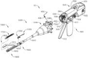
図1及び図2は、様々な異なる外科的処置を実施するために使用し得る、モータ駆動式外科用システム10を示す。図示した構成において、外科用システム10は、ハンドル組立体500に動作可能に連結された交換式外科用道具組立体1000を備える。別の外科用システムの態様では、交換式外科用道具組立体1000は、ロボット制御又は自動外科用システムの道具駆動組立体と共に効果的に使用され得る。例えば、本明細書で開示する外科用道具組立体1000は、様々なロボットシステム、器具、構成要素及び方法、例えば、限定されないが、参照によって全体内容が本明細書に組み込まれる米国特許第9,072,535号、発明の名称「SURGICAL STAPLING INSTRUMENTS WITH ROTATABLE STAPLE DEPLOYMENT ARRANGEMENTS」に開示されるものと共に使用されてもよい。1 and 2 show a motorized
図示した態様において、ハンドル組立体500は、臨床医により把持及び操作することが可能なピストルグリップ部分504を含むハンドルハウジング502を備えることができる。以下で簡潔に論じるように、ハンドル組立体500は、様々な制御運動を生成して交換式外科用道具組立体1000の対応する部分に適用するように構成された複数の駆動システムを動作可能に支持する。図2に示すように、ハンドル組立体500は、複数の駆動システムを動作可能に支持するハンドルフレーム506を更に含むことができる。例えば、ハンドルフレーム506は、全般的に510として示される「第1の」、又は閉鎖駆動システムを動作可能に支持することができ、これを用いて、交換式外科用道具組立体1000に開閉運動を適用することができる。少なくとも1つの形態では、閉鎖駆動システム510は、ハンドルフレーム506により枢動可能に支持される閉鎖トリガ512の形態のアクチュエータを含んでもよい。このような構成により、臨床医が閉鎖トリガ512を操作することが可能になり、これにより、臨床医がハンドル組立体500のピストルグリップ部分504を把持する場合に、閉鎖トリガ512は、開始位置又は「非作動」位置から「作動」位置へ、より具体的には完全圧縮位置又は完全作動位置へと、容易に枢動できるようになっている。使用中、閉鎖駆動システム510を作動させるために、臨床医は、閉鎖トリガ512を、ピストルグリップ部分504に向かって押し下げる。参照によって全体内容が本明細書に組み込まれる、米国特許出願第14/226,142号、発明の名称「SURGICAL INSTRUMENT COMPRISING A SENSOR SYSTEM」(現在は米国特許出願公開第2015/0272575号)に更に詳細に記載されるように、臨床医が閉鎖トリガ512を完全に押し下げ、完全に閉じたストロークを達成するとき、閉鎖駆動システム510は、閉鎖トリガ512を、完全に押し下げられた位置又は完全に作動した位置にロックするように構成されている。臨床医が閉鎖トリガ512をロック解除して非作動位置へと付勢させるように所望する場合、臨床医は、単純に、閉鎖解放ボタン組立体518を活性化させ、これにより、閉鎖トリガを非作動位置まで戻すことが可能である。閉鎖解放ボタン組立体518はまた、閉鎖トリガ512の位置を追跡するために、ハンドル組立体500内のマイクロコントローラと連通する様々なセンサと相互作用するように構成されてもよい。閉鎖解放ボタン組立体518の構成及び動作に関する更なる詳細は、米国特許出願公開第2015/0272575号に見出すことができる。In the illustrated embodiment, the
少なくとも1つの形態では、ハンドル組立体500及びハンドルフレーム506は、取り付けられている交換式外科用道具組立体の対応する部分に発射運動を適用するように構成されている、本明細書で発射駆動システム530と呼ばれる別の駆動システムを動作可能に支持していてもよい。米国特許出願公開第2015/0272575号に詳細に記載されるように、発射駆動システム530は、ハンドル組立体500のピストルグリップ部分504内に位置する電動モータ505を使用してもよい。様々な形態では、モータ505は、最大回転数が例えば約25,000RPMのブラシ付きDC駆動モータであってもよい。別の構成において、モータ505はブラシレスモータ、コードレスモータ、同期モータ、ステッパモータ、又は任意の他の好適な電動モータを含んでよい。モータ505は、電源522によって給電されてもよく、電源522は、一形態では、着脱可能なパワーパックを備えてもよい。パワーパックは、その中にある複数のリチウムイオン(「LI」)電池又は他の好適な電池を支持してもよい。直列又は並列で接続した複数の電池を、外科用システム10のための電源522として使用することができる。加えて、電源522は、交換可能及び/又は再充電可能であってもよい。In at least one form, the
電動モータ505は、長手方向に移動可能な駆動部材540(図3)を、モータの極性に応じて、遠位方向及び近位方向で軸方向に駆動させるように構成されている。例えば、モータ505がある回転方向に駆動すると、長手方向に移動可能な駆動部材は、遠位方向「DD」に軸方向に駆動することになる。モータ505が、反対の回転方向に駆動すると、長手方向に移動可能な駆動部材540は、近位方向「PD」に軸方向に駆動することになる。ハンドル組立体500は、スイッチ513を含んでもよく、スイッチ513は、電源522によって電動モータ505に適用される極性を逆転させるか、又は別の方法でモータ505を制御するように構成されてもよい。ハンドル組立体500はまた、駆動部材の位置及び/又は駆動部材が移動する方向を検出するように構成されている、1つ又は複数のセンサ(図示せず)を含むことができる。モータ505の作動は、閉鎖トリガ512に隣接しており、ハンドル組立体500上で枢動可能に支持される、発射トリガ(図示せず)により制御可能である。発射トリガは、非作動位置と作動位置との間で枢動されてよい。発射トリガは、バネ若しくはその他の付勢構成により非作動位置へと付勢されてよく、これにより、臨床医が発射トリガを解放する場合に、それがバネ若しくは付勢構成により非作動位置へと枢動する、又は別の方法で戻されてよい。少なくとも1つの形態では、発射トリガは、閉鎖トリガ512の「機外」に配置され得る。米国特許出願公開第2015/0272575号に記載されるように、ハンドル組立体500には、発射トリガの不注意による作動を防ぐために、発射トリガ安全ボタン(図示せず)が設けられていてもよい。閉鎖トリガ512が非作動位置にある場合、安全ボタンはハンドル組立体500の中に入っており、臨床医は、これに容易に触ることができず、発射トリガの作動を防ぐ安全位置と、発射トリガが発射し得る発射位置との間を移動させることはできない。臨床医が閉鎖トリガを押し下げる際に、安全ボタン及び発射トリガが下方に枢動し、次に、臨床医による操作が可能になる。The
少なくとも1つの形態では、長手方向に移動可能な駆動部材540は、モータと連係する対応する駆動歯車構成(図示せず)との噛み合い係合ために、その上に形成された歯のラック542を有してよい。図3を参照されたい。これらの特徴に関する更なる詳細は、米国特許出願公開第2015/0272575号に見出すことができる。しかし、少なくとも1つの構成において、長手方向に移動可能な駆動部材は、不注意によるRFエネルギーからその構成を保護するために絶縁されている。少なくとも1つの形態はまた、臨床医が長手方向に移動可能な駆動部材を手動で後退させ、モータ505を使用できないようにすることが可能なように構成された、手動で作動可能な「緊急離脱」組立体を含む。緊急離脱組立体は、解放可能なドア部550の下のハンドル組立体500内に格納されたレバー又は緊急離脱ハンドル組立体を含んでもよい。図2を参照されたい。レバーは、駆動部材内の歯とラチェット係合するように、手動で枢動するように構成されてもよい。したがって、臨床医は、緊急離脱ハンドル組立体を使用して駆動部材540を手動で後退させ、駆動部材を近位方向「PD」にラチェットさせることができる。その開示全体が本明細書に参照により組み込まれている、米国特許第8,608,045号(表題「POWERED SURGICAL CUTTING AND STAPLING APPARATUS WITH MANUALLY RETRACTABLE FIRING SYSTEM」)は、本明細書にて開示した様々な交換式外科用道具組立体のいずれか1つと共に使用可能でもある、緊急離脱構成、並びに他の構成要素、構成、及びシステムについて開示している。In at least one configuration, the longitudinally
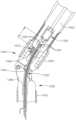
図示した態様において、交換式外科用道具組立体1000は、第1ジョー1600及び第2ジョー1800を備える外科用エンドエフェクタ1500を含む。ある構成において、第1ジョーは、中に従来の(機械式)外科用ステープル/締結具カートリッジ1400(図4)、又は高周波(RF)カートリッジ1700(図1及び図2)を動作可能に支持するように構成された細長通路1602を備える。第2ジョー1800は、細長通路1602に対して枢動可能に支持されるアンビル1810を備える。アンビル1810は、閉鎖駆動システム510を作動させることにより、開位置と閉位置との間を、細長通路1602内で支持された外科用カートリッジに向かうように、及びそこから離れるように選択的に移動されてもよい。図示した構成において、アンビル1810は、シャフト軸SAを横断する枢動軸を中心に選択的枢動移動のために、細長通路1602の近位端部分に枢動可能に支持される。閉鎖駆動システム510の作動により、関節運動コネクタ1920に取り付けられた、近位閉鎖部材又は近位閉鎖管1910の遠位軸移動がもたらされ得る。In the illustrated embodiment, the interchangeable
図4に戻ると、関節運動コネクタ1920は、エンドエフェクタ閉鎖スリーブ又は遠位閉鎖管セグメント1930に移動可能に連結される関節運動コネクタ1920の遠位端から遠位に突出する上部突出部1922及び下部突出部1924を含む。図3を参照されたい。遠位閉鎖管セグメント1930は、上部突出部1932、及び上部突出部1932の近位端から近位に突出する下部突出部(図示せず)を含む。上部二重枢動リンク1940は、それぞれ関節運動コネクタ1920及び遠位閉鎖管セグメント1930の上部突出部1922、1932の対応する穴と係合する、近位ピン1941及び遠位ピン1942を含む。同様に、下部二重枢動リンク1944は、それぞれ関節運動コネクタ1920及び遠位閉鎖管セグメント1930の下部突出部1924の対応する穴と係合する、近位ピン1945及び遠位ピン1946を含む。Returning to FIG. 4, the
依然として図4を参照すると、図示した例において、遠位閉鎖管セグメント1930は、アンビル1810の対応する部分と対応し、遠位閉鎖管セグメント1930が開始位置に向かって近位方向PDに後退すると、アンビル1810に開運動を適用する、正ジョー開口部特徴部又はタブ1936、1938を含む。アンビル1810の開閉に関する更なる詳細は、その開示全体が参照により本明細書に組み込まれている、同日に出願された米国特許出願(表題「SURGICAL INSTRUMENT WITH POSITIVE JAW OPENING FEATURES」)(代理人整理番号END8208USNP/170096)に見出すことができる。4, in the illustrated example, the distal
図5に示すように、少なくとも1つの構成において、交換式外科用道具組立体1000は、上にノズル組立体1240を動作可能に支持する道具シャーシ1210を備える、道具フレーム組立体1200を含む。その全体が参照により本明細書に組み込まれている、同日に出願された米国特許出願(表題「SURGICAL INSTRUMENT WITH AXIALLY MOVABLE CLOSURE MEMBER」)(代理人整理番号END8209USNP/170097)にて更に詳細に論じられるように、道具シャーシ1210及びノズル構成1240は、道具シャーシ1210に対してシャフト軸SAを中心にした外科用エンドエフェクタ1500の回転を容易にする。このような回転移動は、図1において矢印Rにより示される。図4及び図5にもまた示すように、交換式外科用道具組立体1000は、近位閉鎖管1910を動作可能に支持するスパイン組立体1250を含み、外科用エンドエフェクタ1500に連結されている。様々な状況において、組み立てを容易にするために、スパイン組立体1250は、スナップ形成体、接着剤、溶接などにより互いに接続された、上部スパインセグメント1251及び下部スパインセグメント1252から作製可能である。組み立てられた形態において、スパイン組立体1250は、道具シャーシ1210内に回転可能に支持される近位端1253を含む。ある構成では例えば、スパイン組立体1250の近位端1253は、道具シャーシ1210内で支持されるように構成されたスパインベアリング(図示せず)に結合されている。このような構成により、スパイン組立体1250の道具シャーシへの取り付けが容易になり、スパイン組立体1250が道具シャーシ1210に対してシャフト軸SAを中心に選択的に回転可能となる。5, in at least one configuration, the interchangeable
図4に示すように、上部スパインセグメント1251は上部ラグ固定特徴部1260で終了し、下部スパインセグメント1252は、下部ラグ固定特徴部1270で終了する。上部ラグ固定特徴部1260は、中に上部固定リンク1264を固定するように支持するように適合された、ラグスロット1262が中に形成される。同様に、下部ラグ固定特徴部1270は、中に下部固定リンク1274を固定するように支持するように適合された、ラグスロット1272が中に形成される。上部固定リンク1264は、シャフト軸SAからずれた枢動ソケット1266を中に含む。枢動ソケット1266は、中に、通路キャップ上に形成された枢動ピン1634、又は細長通路1602の近位端部分1610に取り付けられた通路キャップ又はアンビル保持装置1630を回転可能に受容するように適合されている。下部固定リンク1274は、細長通路1602の近位端部分1610内に形成された枢動穴1611内に受容されるように適合された、下部枢動ピン1276を含む。下部枢動ピン1276及び枢動穴1611は、シャフト軸SAからずれている。下部枢動ピン1276は枢動ソケット1266と垂直に連動し、それを中心として外科用エンドエフェクタ1500がシャフト軸SAに対して関節運動し得る関節運動軸AAを画定する。図1を参照されたい。関節運動軸AAはシャフト軸SAを横断するものの、少なくとも1つの構成において、関節運動軸AAはシャフト軸SAから水平にずれており、シャフト軸SAと交差しない。As shown in FIG. 4 , the
図5に戻ると、近位閉鎖管1910の近位端1912は、近位閉鎖管セグメント1910内の環状溝1915に位置するコネクタ1916により、閉鎖シャトル1914に回転可能に連結されている。閉鎖シャトル1914は道具シャーシ1210内で軸移動のために支持され、道具シャーシ1210がハンドルフレーム506に連結されたときに閉鎖駆動システム510に係合するように構成された一対のフック1917を、閉鎖シャトル1914上に有する。道具シャーシ1210は、道具シャーシ1210をハンドルフレーム506に解放可能に掛け留めするための掛留組立体1280を、更に支持する。道具シャーシ1210及び掛留組立体1280に関する更なる詳細は、その開示全体が参照により本明細書に組み込まれている、同日に出願された米国特許出願(表題「SURGICAL INSTRUMENT WITH AXIALLY MOVABLE CLOSURE MEMBER」)(代理人整理番号END8209USNP/170097)に見出すことができる。Returning to FIG. 5 , the
ハンドル組立体500内の発射駆動システム530は、交換式外科用道具組立体1000内で動作可能に支持された発射システム1300に、動作可能に連結されるように構成されている。発射システム1300は、発射駆動システム530により適用される、対応する発射運動に応答して、遠位方向及び近位方向に軸移動されるように構成された、中間発射シャフト部分1310を含むことができる。図4を参照されたい。図5に示すように、中間発射シャフト部分1310の近位端1312は、ハンドル組立体500内の発射駆動システム530の長手方向に移動可能な駆動部材540の遠位端の上にある、取り付けクレードル544(図3)内に封止されるように構成された、近位端1312の上に形成された発射シャフト取り付けラグ1314を有する。このような構成により、発射駆動システム530の作動時に、中間発射シャフト部分1310の軸移動が容易になる。図示した例において、中間発射シャフト部分1310は、遠位切断部分又はナイフバー1320に取り付けられるように構成されている。図4に示すように、ナイフバー1320は、発射部材又はナイフ部材1330に接続されている。ナイフ部材1330は、その上に組織切断刃1334を動作可能に支持する、ナイフ本体1332を備える。ナイフ本体1332は、アンビル係合タブ又は特徴部1336、及び通路係合特徴部又は足部1338を更に含むことができる。アンビル係合特徴部1336は、ナイフ部材1330がエンドエフェクタ1500を通って遠位に前進したときに、更なる閉鎖運動をアンビル1810に適用するように機能し得る。The firing
図示した例において、外科用エンドエフェクタ1500は関節運動システム1360により、関節運動軸AAを中心として選択的に関節運動可能である。一形態において、関節運動システム1360は、関節運動リンク1380に枢動可能に連結された近位関節運動ドライバ1370を含む。図4に最も具体的に確認できるように、ずれ取り付けラグ1373が、近位関節運動ドライバ1370の遠位端1372に形成される。枢動穴1374がずれ取り付けラグ1373の中に形成され、関節運動リンク1380の近位端1381に形成された近位リンクピン1382を、中に枢動可能に受容するように構成されている。関節運動リンク1380の遠位端1383は、細長通路1602の近位端部分1610に形成された通路ピン1618を、中に枢動可能に受容するように構成された枢動穴1384を含む。したがって、近位関節運動ドライバ1370の軸移動により、関節運動が細長通路1602に適用され、これによって、外科用エンドエフェクタ1500がスパイン組立体1250に対して、関節運動軸AAを中心に関節移動する。様々な状況において、近位関節運動ドライバ1370が近位方向又は遠位方向に移動していないときに、近位関節運動ドライバ1370が、関節運動ロック1390により、所定の位置で維持されてもよい。関節運動ロック1390の例示的な形態に関する更なる詳細は、その開示全体が参照により本明細書に組み込まれている、同日に出願された米国特許出願(表題「SURGICAL INSTRUMENT COMPRISING AN ARTICULATION SYSTEM LOCKABLE TO A FRAME」)(代理人整理番号END8217USNP/170102)に見出すことができる。In the illustrated example, the
上記に加えて更に、交換式外科用道具組立体1000は、近位関節運動ドライバ1310を発射システム1300に選択的にかつ解放可能に連結するように構成することができる、シフタ組立体1100を含む。図5に示すように、例えば、一形態において、シフタ組立体1100は、発射システム1300の中間発射シャフト部分1310の周りに配置された、ロックカラー、又はロックスリーブ1110を含み、ロックスリーブ1110は、ロックスリーブ1110が近位関節運動ドライバ1370を発射部材組立体1300に動作可能に連結させる係合位置と、近位関節運動ドライバ1370が発射部材組立体1300に動作可能に連結されない係合解除位置との間を回転することができる。ロックスリーブ1110が係合位置にあるとき、発射部材組立体1300が遠位に移動することにより、近位関節運動ドライバ1370が遠位に移動することができ、これに対応して、発射部材組立体1300が近位に移動することにより、近位関節運動ドライバ1370が近位に移動することができる。ロックスリーブ1110がその係合解除位置にあるとき、発射部材組立体1300の移動は近位関節運動ドライバ1370に伝達されず、その結果、発射部材組立体1300は近位関節運動ドライバ1370から独立して移動することができる。様々な状況下では、近位関節運動ドライバ1370は、近位関節運動ドライバ1370が発射部材組立体1300によって近位方向又は遠位方向に移動されていないとき、関節運動ロック1390によって所定の位置に保持され得る。Further to the above, the interchangeable
図示した構成において、発射部材組立体1300の中間発射シャフト部分1310は、中に駆動ノッチ1316が形成された、2つの対向する平坦な側面を有して形成される。図5を参照されたい。図5でもまた確認できるように、ロックスリーブ1110は、中間発射シャフト部分1310を受容するように構成された長手方向アパーチャを含む、円筒形、又は少なくとも実質的に円筒形の本体を備える。ロックスリーブ1110は、ロックスリーブ1110がある位置にあるときに、中間発射シャフト部分1310内の駆動ノッチ1316の対応する部分の中に係合可能に受容され、別の位置にあるときに、駆動ノッチ1316内には受容されない、直径の反対方向に内側に向き合う、ロック突出部を備えることができ、これにより、ロックスリーブ1110と中間発射シャフト1310との間での、相対的な軸運動を可能にする。図5に更に確認できるように、ロックスリーブ1110は、近位関節運動ドライバ1370の近位端のノッチ1375内に移動可能に受容されるような寸法である、ロック部材1112を更に含む。このような構成により、近位関節運動ドライバ1370内でのノッチ1375との係合のために、適切な位置に残りながら、又は係合しながら、ロックスリーブ1110はわずかに回転して、中間発射シャフト部分1310と係合し、係合解除することができる。例えば、ロックスリーブ1110がその係合位置にある場合、ロック突出部は、中間発射シャフト部分1310の駆動ノッチ1316内に配置され、これにより、遠位押力及び/又は近位引張力が発射部材組立体1300からロックスリーブ1110へと伝達され得る。このような軸方向の押運動、又は引張運動は次に、ロックスリーブ1110から近位関節運動ドライバ1370へと伝達されることにより、外科用エンドエフェクタ1500を関節運動させる。実際には、発射部材組立体1300、ロックスリーブ1110、及び近位関節運動ドライバ1370は、ロックスリーブ1110がその係合(関節運動)位置にあるときに共に移動する。他方で、ロックスリーブ1110がその係合解除位置にあるとき、ロック突出部は中間発射シャフト部分1310の駆動ノッチ1316内には受容されず、結果的に、遠位押力及び/又は近位引張力は、発射部材組立体1300からロックスリーブ1110(そして、近位関節運動ドライバ1370)に伝達され得ない。In the illustrated configuration, the intermediate
図示した例において、係合位置と係合解除位置との間での、ロックスリーブ1110の相対移動は、近位閉鎖管1910と連係するシフタ組立体1100により、制御されてもよい。依然として図5を参照すると、シフタ組立体1100は、ロックスリーブ1110の外側周辺に形成された鍵溝内に摺動可能に受容されるように構成された、シフタキー1120を更に含む。このような構成により、シフタキー1120がロックスリーブ1110に対して軸移動することが可能となる。その開示全体が参照により本明細書に組み込まれている、同日に出願された米国特許出願(表題「SURGICAL INSTRUMENT WITH AXIALLY MOVABLE CLOSURE MEMBER」)(代理人整理番号END8209USNP/170097)に更に詳細に論じられているように、シフタキー1120の一部は、近位閉鎖管部分1910内でカム開口部(図示せず)とカム作用により相互作用するように、構成されている。また、図示した例では、シフタ組立体1100は、近位閉鎖管部分1910の近位端部分に回転可能に受容される、スイッチドラム1130を更に含む。シフタキー1120の一部は、スイッチドラム1130内の軸スロットセグメントを通って延び、スイッチドラム1130内の弓状スロットセグメント内に移動可能に受容される。スイッチドラムねじりバネ1132がスイッチドラム1130に固定され、ノズル組立体1240の一部に係合して、近位閉鎖管部分1910内のカム開口部の端部部分にシフタキー1120の一部が到達するまで、スイッチドラム1130を回転させる役割を果たすねじれ付勢又は回転を適用する。この位置にあるとき、スイッチドラム1130はねじれ付勢をシフタキー1120にもたらすことにより、ロックスリーブ1110を回転させて、中間発射シャフト部分1310との係合位置にする。この位置はまた、近位閉鎖管1910(及び、遠位閉鎖管セグメント1930)の非作動構成に対応している。In the illustrated example, the relative movement of the
ある構成では例えば、近位閉鎖管1910が非作動構成にある(アンビル1810が、細長通路1602に固定されたカートリッジから離れて開位置にある)とき、中間発射シャフト部分1310が作動することにより、近位関節運動ドライバ1370が軸移動し、エンドエフェクタ1500の関節運動が容易になる。ユーザが外科用エンドエフェクタ1500を所望の向きに関節運動させると、次いでユーザは、近位閉鎖管部分1910を作動させることができる。近位閉鎖管部分1910を作動させることにより、遠位閉鎖管セグメント1930の遠位移動がもたされ、最終的に閉鎖運動がアンビル1810に適用される。近位閉鎖管部分1910のこの遠位移動により、その中のカム開口部において、シフタキー1120のカム部分とのカム作用による相互作用がもたされることにより、シフタキー1120が作動方向に、ロックスリーブ1110を回転させる。ロックスリーブ1110のこのような回転により、中間発射シャフト部分1310内で、駆動ノッチ1316からロック突出部が係合解除される。このような構成にあるとき、発射駆動システム530が作動して、近位関節運動ドライバ1370を作動させることなく、中間発射シャフト部分1310を作動させることができる。スイッチドラム1130及びロックスリーブ1110の動作、並びに、本明細書で記載される様々な交換式外科用道具組立体と共に用いることができる、代替の関節運動及び発射駆動構成に関する更なる詳細は、これらの開示全体が、参照により本明細書に組み込まれる、米国特許出願第13/803,086号(現在は米国特許公開第2014/0263541号)及び米国特許出願第15/019,196号に見出すことができる。In one configuration, for example, when the
図5及び図15にもまた示すように、交換式外科用道具組立体1000は、ノズル組立体1240を回転させることにより、道具シャーシ1210に対するシャフト軸SAを中心にしたシャフト及びエンドエフェクタ1500の回転移動を容易にしながら、電力を外科用エンドエフェクタ1500に/から伝えし、かつ/又は、外科用エンドエフェクタ1500に/から、信号を通信するように構成可能な、搭載された回路基板1152の背後にある、スリップリング組立体1150を備えることができる。図15に示すように、少なくとも1つの構成において、搭載された回路基板1152は、例えば、ハンドル組立体500又はロボットシステムコントローラ内で支持されるマイクロプロセッサ560と通信する、ハウジングコネクタ562(図9)と連係するように構成された、搭載されたコネクタ1154を含む。スリップリング組立体1150は、搭載された回路基板1152と連係する近位コネクタ1153と連係するように構成されている。スリップリング組立体1150及び関連するコネクタに関する更なる詳細は、それらの各全体が本明細書に参考として組み込まれる、米国特許出願第13/803,086号、現在は米国特許出願公開第2014/0263541号、及び米国特許出願第15/019,196号、並びにその全体が参照として本明細書に組み込まれる、米国特許出願第13/800,067号、発明の名称「STAPLE CARTRIDGE TISSUE THICKNESS SENSOR SYSTEM」(現在は米国特許出願公開第2014/0263552号)に見出され得る。5 and 15, the interchangeable
本明細書で開示した交換式外科用道具組立体1000の例示的なバージョンを、ナイフ部材により組織の切断を容易にし、切断組織を、高周波(RF)エネルギーを用いて封止するように構成された、標準的な(機械式)外科用締結具カートリッジ1400又はカートリッジ1700と共に使用することができる。図4に再び戻ると、従来の、又は標準的な機械式カートリッジ1400が示されている。このようなカートリッジ構成は既知であり、細長通路1602内で着脱可能に受容され支持されるような寸法、及び形状である、カートリッジ本体1402を備えることができる。例えば、カートリッジ本体1402は、細長通路1602とスナップ係合して、着脱可能に保持されるように構成されてもよい。カートリッジ本体1402は細長スロット1404を含み、このスロットを通して、ナイフ部材1330の軸移動に適応する。カートリッジ本体1402は、中央に配置された細長スロット1404の各側面の列に位置合わせされた複数のステープルドライバ(図示せず)をその内部に動作可能に支持する。ドライバは、カートリッジ本体1402の上部デッキ表面1410を通って開いている、対応するステープル/締結具ポケット1412と関連付けられる。ステープルドライバのそれぞれは、1つ以上の外科用ステープル又は締結具(図示せず)を支持する。スレッド組立体1420がカートリッジ本体1402の近位端内で支持されており、カートリッジ1400が新しいものであり、発射されていないときには、開始位置においてドライバ及び締結具に近位に位置している。スレッド組立体1420は、複数の傾斜した又は楔形のカム1422を含み、各カム1422は、スロット1404の側面上に位置する締結具又はドライバの特定のラインに対応する。スレッド組立体1420は、アンビルとカートリッジデッキ表面1410との間でクランプ留めされた組織を通ってナイフ部材が遠位に駆動されるときに、ナイフ部材1330により接触され駆動されるように構成されている。ドライバがカートリッジデッキ表面1410に向けて上向きに駆動されると、その上で支持されている締結具(単数又は複数)は、ステープルポケット1412から、アンビルとカートリッジとの間でクランプ留めされた組織を通って駆動される。The exemplary version of the interchangeable
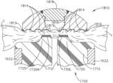
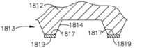
依然として図4を参照すると、少なくとも1つの形態のアンビル1810は、水平に突出し、細長通路1602の近位端部分1610の直立壁1622に形成された、対応するトラニオンクレードル1614の中に枢動可能に受容される、一対のアンビルトラニオン1822を有するアンビル固定部分1820を含む。アンビルトラニオン1822は、通路キャップ又はアンビル保持装置1630により、対応するトラニオンクレードル1614内で枢動可能に保持される。アンビル固定部分1820は、シャフト軸SAを横断する、固定されたアンビル枢動軸を中心にしたアンビル固定部分1820に対する選択的な枢動移動のために、細長通路1602の上で、移動可能に、又は枢動可能に支持される。図6及び図7に示すように、少なくとも1つの形態において、アンビル1810は、例えば導電性金属材料から作製されるアンビル本体部分1812を含み、中にナイフ部材1330を摺動可能に収容するように構成された中央に配置されたアンビルスロット1815の各側面に、中に形成された一連の締結具形成ポケット1814を有するステープル形成下面1813を有する。アンビルスロット1815は、アンビル本体1812を通って長手方向に延びる上部開口部1816へと開口し、発射の間、ナイフ部材1330上にアンビル係合特徴部1336を収容する。従来の機械式外科用ステープル/締結具カートリッジ1400が細長通路1602内に取り付けられると、ステープル/締結具は組織Tを通って駆動され、対応する締結具形成ポケット1814との接触を形成する。アンビル本体1812は上部に開口部を有し、例えば取り付けを容易にすることができる。アンビルキャップ1818を中に挿入し、アンビル本体1812に溶接して開口部を取り囲み、アンビル本体1812の全体の剛性を改善することができる。図7に示すように、RFカートリッジ1700と共にエンドエフェクタ1500の使用を容易にするために、締結具形成下面1813の組織に面しているセグメント1817は、その上に電気絶縁性材料1819を有してよい。4, at least one form of
図示した構成において、交換式外科用道具組立体1000は、全般的に1640として示される発射部材ロックアウトシステムと共に構成される。図8を参照されたい。図8に示すように、細長通路1602は、突出する2つの直立側壁1622を有する底部表面又は底部1620を含む。中央に配置された長手方向通路スロット1624は底部1620を通して形成され、ナイフ部材1330がスロットを通って軸移動することを容易にする。通路スロット1624は、ナイフ部材1330上に通路係合特徴部又は足部1338を収容する長手方向パッセージ1626へと開口している。パッセージ1626は、通路係合特徴部又は足部1338の対応する部分に係合する役割を果たす、内側に延びる2つの出っ張り部分1628を画定する役割を果たす。発射部材ロックアウトシステム1640は、ナイフ部材1330が開始位置にあるときに、それぞれが、通路係合特徴部又は足部1338の対応する部分を受容するように構成された、通路スロット1624の各側面に位置する近位開口部1642を含む。ナイフロックアウトバネ1650は、細長通路1602の近位端1610で支持され、ナイフ部材1330を下に向かって付勢する役割を果たす。図8に示すように、ナイフロックアウトバネ1650は、ナイフ本体1332上に、対応する中央通路係合特徴部1337に係合するように構成された、2つの遠位末端バネアーム1652を含む。バネアーム1652は、中央通路係合特徴部1337を下に向かって付勢するように構成されている。したがって、開始(未発射位置)にあるときに、ナイフ部材1330は下向きに付勢され、通路係合特徴部又は足部1338は、細長1602通路の対応する近位開口部1642内に受容される。そのロック位置にあるとき、ナイフ1330を遠位に前進させようとすると、中央通路係合特徴部1137及び/又は足部1338は、細長通路1602上で直立した出っ張り1654と係合し(図8及び図11)、ナイフ1330は発射できなくなる。In the illustrated configuration, the interchangeable
依然として図8を参照すると、発射部材ロックアウトシステム1640は、発射部材本体1332の遠位端に形成された、又はそこで支持された、ロック解除組立体1660もまた含む。ロック解除組立体1660は、スレッド組立体1420が、未発射の外科用ステープルカートリッジ1400にて開始位置にあるときに、スレッド組立体1420に形成されたロック解除特徴部1426に係合するように構成された、遠位に延びる出っ張り1662を含む。したがって、未発射の外科用ステープルカートリッジ1400が細長通路1602に適切に取り付けられると、ロック解除組立体1660の出っ張り1662が、ナイフ部材1330を上向きに付勢する役割を果たすスレッド組立体1420上でロック解除特徴部1426と接触し、中央通路係合特徴部1137及び/又は足部1338が、通路底部1620内で直立した出っ張り1654を取り除き、ナイフ部材1330の細長通路1602を通っての軸通過を容易にする。部分的に発射されたカートリッジ1400が細長通路に、知らぬ間に取り付けられた場合、スレッド組立体1420は開始位置にはなく、ナイフ部材1330はロック位置にとどまる。8, the firing
ここから、ハンドル組立体500への交換式外科用道具組立体1000の取り付けについて、図3及び図9を参照して記載する。連結プロセスを開始するために、臨床医は、道具シャーシ1210上に形成された先細取り付け部分1212がハンドルフレーム506のダブテールスロット507と整列するように、交換式外科用道具組立体1000の道具シャーシ1210をハンドルフレーム506の遠位端の上方に、又はそれに隣接して配置してもよい。臨床医は、次いで、先細取り付け部分1212を、ハンドルフレーム506の遠位端の対応するダブテール受容スロット507と「動作可能に係合」した状態で着座させるように、外科用道具組立体1000をシャフト軸SAに垂直な取り付け軸IAに沿って移動させてもよい。そうすることで、中間発射シャフト部分1310上の発射シャフト取り付けラグ1314もまた、ハンドル組立体500内の長手方向に移動可能な駆動部材540のクレードル544内に着座され、閉鎖リンク514上にあるピン516の部分が、閉鎖シャトル1914の対応するフック1917内に着座される。本明細書で使用するとき、2つの構成要素の文脈における「動作可能な係合」という用語は、それら2つの構成要素が互いに十分に係合され、それにより、作動運動をそれらに適用すると、構成要素が意図される行為、機能、及び/又は手順を実施し得ることを意味する。本プロセス中にはまた、外科用道具組立体1000の、搭載されたコネクタ1154が、例えばハンドル組立体500又はロボットシステムコントローラ内で支持されたマイクロプロセッサ560と通信するハウジングコネクタ562に連結される。Attachment of the interchangeable
通常の外科的処置の間、臨床医は、標的組織にアクセスするため、患者のトロカール又は他の開口部を通して、外科用エンドエフェクタ1500を手術部位へと導入することができる。そうするとき、臨床医は、典型的には、シャフト軸SAに沿って外科用エンドエフェクタ1500を軸方向に整列させる(非関節運動状態)。外科用エンドエフェクタ1500がトロカールポートを通過すると、例えば、臨床医には、エンドエフェクタ1500を関節運動させて、標的組織に隣接させて有利に配置することが必要とされ得る。これは、アンビル1810が標的組織の上で閉じる前であるため、閉鎖駆動システム510は非作動のままである。この位置にあるとき、発射駆動システム530が作動することにより、関節運動が近位関節運動ドライバ1370に適用される。エンドエフェクタ1500が所望の関節運動位置に達すると、発射駆動システム530は非活性化され、関節運動ロック1390が外科用エンドエフェクタ1500を関節運動位置で保持することができる。次に臨床医は、閉鎖駆動システム510を作動させて、アンビル1810を標的組織の上で閉じることができる。閉鎖駆動システム510をこのように作動させることによってまた、シフタ組立体1100が中間発射シャフト部分1310から近位関節運動ドライバ1370を分離することができる。したがって、標的組織が外科用エンドエフェクタ1500で捕捉されると、臨床医は再び、発射駆動システム530を作動させて、発射部材1330を外科用ステープル/締結具カートリッジ1400、又はRFカートリッジ1700を通して軸方向に前進させ、クランプ留めした組織を切断し、ステープル/締結具を切断した組織Tに発射する。他の閉鎖及び発射装置構成、作動装置構成(共に手持ち型、手動、及び自動又はロボット式)もまた使用して、本開示の範囲を逸脱することなく、外科用道具組立体1000の閉鎖システム構成要素、関節運動システム構成要素、及び/又は発射システム構成要素の軸移動を制御することができる。During a typical surgical procedure, a clinician may introduce the
上で示したとおり、外科用道具組立体1000は、従来の機械式外科用ステープル/締結具カートリッジ1400及びRFカートリッジ1700と共に使用するように構成されている。少なくとも1つの形態において、RFカートリッジ1700は、凝固用電流を電流経路内の組織に送達しながら、ナイフ部材1330を用いて、アンビル1810とRFカートリッジ1700との間でクランプ留めされた組織の機械的切断を容易にすることができる。組織を機械的に切断し、電流を用いて凝固させる代替的な構成はまた、例えば、米国特許第5,403,312号;同第7,780,663号、及び米国特許出願第15/142,609号(表題「ELECTROSURGICAL INSTRUMENT WITH ELECTRICALLY CONDUCTIVE GAP SETTING AND TISSUE ENGAGING MEMBERS」)(上記それぞれの参照文献である開示全体は、本明細書に参照により組み込まれている)に開示されている。このような器具により、例えば、止血が改善され、外科的複雑性の減少並びに手術室にいる時間の減少がもたらされ得る。As indicated above, the
図10~図12に示すように、少なくとも1つの構成において、RF外科用カートリッジ1700は、細長通路1602内で着脱可能に受容され支持されるような寸法、及び形状である、カートリッジ本体1710を含む。例えば、カートリッジ本体1710は、細長通路1602とスナップ係合して、着脱可能に保持されるように構成されてもよい。様々な構成において、カートリッジ本体1710はポリマー材料、例えば、液晶ポリマー(LCP)VECTRA(商標)などのエンジニアリング熱可塑性樹脂から作製可能であり、細長通路1602は金属から作製可能である。少なくとも一態様において、カートリッジ本体1710は、カートリッジ本体を通って長手方向に延び、ナイフ1330の長手方向移動を収容する、中央に配置された細長スロット1712を含む。図10及び図11に示すように、一対のロックアウト係合尾部1714は、カートリッジ本体1710から近位に延びる。各ロックアウト係合尾部1714は、通路底部1620の対応する近位開口部部分1642内に受容される寸法である、下側に形成されるロックアウトパッド1716を有する。したがって、カートリッジ1700が細長通路1602に適切に取り付けられると、ロックアウト係合尾部1714は開口部1642及び出っ張り1654を覆い、ナイフ1330を、発射の準備ができたロック解除位置で保持する。10-12, in at least one configuration, the RF
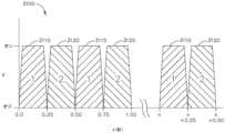
ここで、図10~図13に戻ると、図示した例において、カートリッジ本体1710は、中央に配置された隆起電極パッド1720を有して形成されている。最も具体的には図6に確認できるように、細長スロット1712は、電極パッド1720の中心を通って延び、パッド1720を、左パッドセグメント1720Lと右パッドセグメント1720Rとに分割する役割を果たす。右側フレキシブル回路組立体1730Rは右パッドセグメント1720Rに取り付けられ、左側フレキシブル回路組立体1730Lは左パッドセグメント1720Lに取り付けられている。少なくとも1つの構成では、例えば、右側フレキシブル回路1730Rは、例えば、右側パッド1720Rに取り付けられた右側絶縁体シース/部材1734Rに支持された、取り付けられた、又は埋め込まれた、RF用の、幅広い導電体/導電体、及び、従来のステープル留め用の薄い導電体を含むことができる、複数の導電体1732Rを備える。更に、右側フレキシブル回路組立体1730Rは、「フェーズ1」、即ち近位右側電極1736R、及び「フェーズ2」、即ち遠位右側電極1738Rを含む。同様に、左側フレキシブル回路組立体1730Lは、例えば、左側パッド1720Lに取り付けられた左側絶縁体シース/部材1734Lに支持された、取り付けられた、又は埋め込まれた、RF用の、幅広い導電体/導電体、及び、従来のステープル留め用の薄い導電体を含むことができる、複数の導電体1732Lを備える。更に、左側フレキシブル回路組立体1730Lは、「フェーズ1」、即ち近位左側電極1736L、及び「フェーズ2」、即ち遠位左側電極1738Lを含む。左側導電体1732L及び右側導電体1732Rは、カートリッジ本体1710の遠位端部分に固定された遠位マイクロチップ1740に取り付けられている。ある構成では例えば、右側フレキシブル回路1730R及び左側フレキシブル回路1730Lはそれぞれ、約0.025インチの全体幅「CW」を有することができ、電極1736R、1736L、1738R、1738Rのそれぞれは、例えば約0.010インチの幅「EW」を有する。図13を参照されたい。しかし、他の幅/寸法が想到され、代替の態様において用いられてよい。10-13, in the illustrated example, the
少なくとも1つの構成では、RFエネルギーは、従来のRF発電機400により、供給リード402を通って外科用道具組立体1000に供給される。少なくとも1つの構成では、供給リード402は、搭載された回路基板1152上のセグメント化RF回路1160に取り付けられた、対応する雌型コネクタ410にプラグ接続されるように構成された、雄型プラグ組立体406を含む。図15を参照されたい。このような構成により、発電機400から供給リード402を巻回することなく、ノズル組立体1240を回転させることによって、道具シャーシ1210に対するシャフト軸SAを中心にしたシャフト及びエンドエフェクタ1500の回転移動が容易になる。搭載されたオン/オフ電源スイッチ420が、RF発電機のオンとオフとを切り替えるために、掛留組立体1280及び道具シャーシ1210上に支持されている。道具組立体1000がハンドル組立体500又はロボットシステムに動作可能に連結されているとき、搭載されたセグメント化RF回路1160は、コネクタ1154及び562を介してマイクロプロセッサ560と通信する。図1に示すように、ハンドル組立体500は、封止、ステープル留め、ナイフ位置、カートリッジのステータス、組織、温度の進行に関する情報を確認するために表示スクリーン430もまた含むことができる。図15でもまた確認できるように、スリップリング組立体1150は、フレキシブルシャフト回路ストリップを含む遠位コネクタ1162、又は、RF用に使用する、関係する活動及びより幅広い導電体1168をステープル留めするための、狭い複数の導電体1166を含み得る組立体1164と連係する。図14及び図15に示すように、フレキシブルシャフト回路ストリップ1164は、ナイフバー1320を形成する積層板又は積層されたバー1322の間で、中心で支持される。このような構成により、エンドエフェクタ1500の関節運動の間に十分な硬さを残したまま、ナイフバー1320とフレキシブルシャフト回路ストリップ1164とを十分に撓曲させることが容易となり、ナイフ部材1330がクランプ留めされた組織を通して遠位に前進することが可能となる。In at least one configuration, RF energy is supplied to the
図10に再び戻ると、少なくとも1つの図示した構成において、細長通路1602は、細長通路1602の近位端1610から、細長通路底部1620の遠位位置1623に延びるくぼみ1621内で支持された、通路回路1670を含む。通路回路1670は、電気接触のために、フレキシブルシャフト回路ストリップ1164の遠位接触部分1169と接触する近位接触部分1672を含む。通路回路1670の遠位端1674は、通路壁1622の1つに形成された、対応する壁のくぼみ1625内に受容され、折りたたまれ、通路壁1622の上部縁1627に取り付けられる。一連の、対応する露出した接触部1676は、図10に示すように、通路回路1670の遠位端1674内に備えられる。図10でもまた確認できるように、フレキシブルカートリッジ回路1750の端部1752は遠位マイクロチップ1740に取り付けられ、カートリッジ本体1710の遠位端部分に固定される。別の端部1754はカートリッジデッキ表面1711の縁を覆って折りたたまれ、通路回路1670の露出した接触部1676と電気接触するように構成された、露出した接触部1756を含む。したがって、RFカートリッジ1700が細長通路1602に取り付けられると、電極と遠位マイクロチップ1740が給電され、フレキシブルカートリッジ回路1750とフレキシブル通路回路1670とフレキシブルシャフト回路1164とスリップリング組立体1150との接触部を介して、搭載された回路基板1152と通信する。Returning again to FIG. 10, in at least one illustrated configuration, the
図16A~図16Bは、本開示の一態様に従った、2つの図面にまたがる、図1の外科用器具10の制御回路700のブロック図である。主に図16A~図16Bを参照すると、ハンドル組立体702は、モータドライバ715により制御可能であり、外科用器具10の発射システムにより用いられることが可能な、モータ714を備えることができる。様々な形態において、モータ714は、約25,000RPMの最大回転速度を有する、ブラシ付きDC駆動モータであってよい。別の構成において、モータ714はブラシレスモータ、コードレスモータ、同期モータ、ステッパモータ、又は任意の他の好適な電動モータを含んでよい。モータドライバ715は、例えば、電界効果トランジスタ(FET)719を含むHブリッジドライバを備えてもよい。モータ714は、制御電力を外科用器具10に供給するためにハンドル組立体500に解放可能に固定された電源組立体706により給電されてもよい。電源組立体706は、外科用器具10に給電するための電源として使用され得る、直列に接続された複数の電池を備えてもよい。特定の状況下では、電源組立体706の電池セルは、交換可能及び/又は再充電可能であってよい。少なくとも1つの例では、電池セルは、電源組立体706に別個に連結可能であり得るリチウムイオン電池であってよい。16A-16B are block diagrams of a
シャフト組立体704は、シャフト組立体704と電源組立体706がハンドル組立体702に連結されている間に、インタフェースを介して安全コントローラ及び電力管理コントローラ716と通信可能である、シャフト組立体コントローラ722を含むことができる。例えば、インタフェースは、シャフト組立体704及び電源組立体706がハンドル組立体702に連結されている間にシャフト組立体コントローラ722と電力管理コントローラ716との間の電気通信を可能にするために、対応するシャフト組立体電気コネクタとの連結係合のために1つ以上の電気コネクタを含み得る第1のインタフェース部分725、及び、対応する電源組立体電気コネクタとの連結係合のために1つ以上の電気コネクタを含み得る第2のインタフェース部分727を備え得る。インタフェースを介して1つ以上の通信信号を送信して、取り付けられて交換式シャフト組立体704の1つ以上の電力要件を電力管理コントローラ716に送信することができる。それに応じて、電力管理コントローラは、取り付けられたシャフト組立体704の電力要件に従って、以下に更に詳細に記載されているように、電源組立体706の電池の電力出力を変調し得る。コネクタは、ハンドル組立体702の、シャフト組立体704及び/又は電源組立体706への機械的連結係合の後に活性化して、シャフト組立体コントローラ722と電力管理コントローラ716との電気的通信を可能にすることができるスイッチを備えることができる。The
インタフェースは、例えば、ハンドル組立体702に収められたメインコントローラ717を通して、通信信号の経路指定を行うことにより、電力管理コントローラ716とシャフト組立体コントローラ722との1つ以上のこのような通信信号の伝達を容易にすることができる。他の状況下では、シャフト組立体704及び電源組立体706がハンドル組立体702に連結されている間、インタフェースは、ハンドル組立体702を介した電力管理コントローラ716とシャフト組立体コントローラ722との間の直接線の通信を容易にし得る。The interface may facilitate transmission of one or more such communication signals between the
メインコントローラ717は、Texas Instrumentsの商標名ARM Cortexとして知られるものなど、任意のシングルコア又はマルチコアプロセッサであってよい。一態様では、メインコントローラ717は、例えば、その詳細が製品データシートで入手可能である、最大40MHzの256KBのシングルサイクルフラッシュメモリ若しくは他の不揮発性メモリのオンチップメモリ、性能を40MHz超に改善するためのプリフェッチバッファ、32KBのシングルサイクルシリアルランダムアクセスメモリ(SRAM)、StellarisWare(登録商標)ソフトウェアを搭載した内部読み出し専用メモリ(ROM)、2KBの電気的消去可能プログラマブル読み出し専用メモリ(EEPROM)、1つ以上のパルス幅変調(PWM)モジュール、1つ以上の直交エンコーダ入力(QEI)アナログ、12個のアナログ入力チャネルを備える1つ以上の12ビットアナログ-デジタル変換器(ADC)を含む、Texas Instrumentsから入手可能なLM4F230H5QR ARM Cortex-M4Fプロセッサコアであってもよい。The
安全コントローラは、やはりTexas Instrumentsの商標名Hercules ARM Cortex R4として知られている、TMS570及びRM4xなど、2つのコントローラベースファミリを備える安全コントローラプラットフォームであってよい。安全コントローラは、拡張性のある性能、接続性、及びメモリの選択肢を提供しながら、高度な集積型安全機構を提供するために、中でも特に、IEC61508及びISO26262の安全限界用途専用に構成されてもよい。The safety controller may be a safety controller platform with two controller base families, such as TMS570 and RM4x, also known by Texas Instruments under the trade name Hercules ARM Cortex R4. The safety controller may be configured specifically for IEC 61508 and ISO 26262 safety limit applications, among others, to provide advanced integrated safety mechanisms while offering scalable performance, connectivity, and memory options.
電源組立体706は、電力管理回路を含んでよく、電力管理回路は、電力管理コントローラ716、電力変調器738、及び電流感知回路736を含み得る。シャフト組立体704及び電源組立体706がハンドル組立体702に連結されている間に、電力管理回路は、シャフト組立体704の電力要件に基づいて電池の電力出力を変調するように構成され得る。電力管理コントローラ716は、電源組立体706の電力出力の電力変調器738を制御するようにプログラムされ得、電流感知回路736は、電源組立体706の電力出力を監視して、電池の電力出力に関するフィードバックを電力管理コントローラ716に提供するように用いられ得るため、電力管理コントローラ716は、電源組立体706の電力出力を調節して、所望の出力を維持することができる。電力管理コントローラ716及び/又はシャフト組立体コントローラ722はそれぞれ、多数のソフトウェアモジュールを記憶可能な1つ以上のプロセッサ、及び/又はメモリユニットを備えることができる。The
外科用器具10(図1~図5)は、間隔フィードバックをユーザに提供するための装置を含み得る、出力装置742を備えることができる。このような装置は、例えば、視覚的フィードバック装置(例えば、LCD表示スクリーン、LEDインジケータ)、可聴フィードバック装置(例えば、スピーカー、ブザー)又は触覚フィードバック装置(例えば、触覚作動装置)を含んでもよい。このような装置は、例えば、視覚的フィードバック装置(例えば、LCDディスプレイスクリーン、LEDインジケータ)、可聴フィードバック装置(例えば、スピーカー、ブザー)又は触覚フィードバック装置(例えば、触覚作動装置)を含んでもよい。特定の状況下では、出力装置742は、ハンドル組立体702に含まれ得るディスプレイ743を備えてよい。シャフト組立体コントローラ722及び/又は電力管理コントローラ716は、出力装置742を介して外科用器具10のユーザにフィードバックを提供し得る。インタフェースは、シャフト組立体コントローラ722及び/又は電力管理コントローラ716を出力装置742に接続するように構成することができる。出力装置742は代わりに、電源組立体706と一体化することができる。このような状況下では、シャフト組立体704がハンドル組立体702に連結されている一方で、出力装置742とシャフト組立体コントローラ722との間の通信はインタフェースを介して成し遂げられ得る。The surgical instrument 10 (FIGS. 1-5) may include an
制御回路700は、電動外科用器具10の動作を制御するように構成された回路セグメントを備える。安全コントローラセグメント(セグメント1)は、安全コントローラ、及びメインコントローラ717セグメント(セグメント2)を備える。安全コントローラ及び/又はメインコントローラ717は、加速度セグメント、ディスプレイセグメント、シャフトセグメント、エンコーダセグメント、モータセグメント、及び電力セグメントなどの1つ以上の追加の回路セグメントと相互作用するように構成されている。回路セグメントのそれぞれは、安全コントローラ及び/又はメインコントローラ717に連結されてよい。メインコントローラ717もまた、フラッシュメモリに連結される。メインコントローラ717は、シリアル通信インタフェースもまた備える。メインコントローラ717は、例えば、1つ以上の回路セグメント、電池、及び/又は複数のスイッチに連結された、複数の入力を備える。セグメント化回路は、例えば、電動外科用器具10内のプリント回路基板組立体(PCBA)など、任意の好適な回路によって実装されてもよい。プロセッサという用語は、本明細書で使用するとき、任意のマイクロプロセッサ、プロセッサ、1つ若しくは複数のコントローラ、又は、コンピュータの中央処理装置(CPU)の機能を1つの集積回路又は最大で数個の集積回路上に組み込んだ、他の基本コンピューティングデバイスを含むと理解されるべきである。メインコントローラ717は、デジタルデータを入力として受理し、メモリに記憶された命令に従ってそのデータを処理し、結果を出力として提供する、多目的のプログラム可能装置である。これは、内部メモリを有するので、逐次的デジタル論理の一例である。制御回路700は、本明細書で記載される1つ以上のプロセスを実装するように構成されてもよい。The
加速度セグメント(セグメント3)は加速度計を備える。加速度計は、電動外科用器具10の移動又は加速度を検出するように構成されている。加速度計からの入力は、スリープモードとの間での遷移、電動外科用器具の配向の識別、及び/又は外科用器具が落下したときの識別に使用されてもよい。いくつかの例では、加速度セグメントは安全コントローラ及び/又はメインコントローラ717に連結される。The acceleration segment (segment 3) comprises an accelerometer. The accelerometer is configured to detect movement or acceleration of the powered
ディスプレイセグメント(セグメント4)は、メインコントローラ717に連結されたディスプレイコネクタを備える。表示コネクタは、メインコントローラ717を、ディスプレイの1つ以上の集積回路ドライバを通して、ディスプレイに連結している。ディスプレイの集積回路ドライバは、ディスプレイと一体化されてよく、かつ/又はディスプレイとは別個に配置されてよい。ディスプレイは、例えば、有機発光ダイオード(OLED)ディスプレイ、液晶ディスプレイ(LCD)、及び/又は任意の他の好適なディスプレイなど、任意の好適なディスプレイを含んでもよい。いくつかの例では、ディスプレイセグメントは安全コントローラに連結される。The display segment (Segment 4) includes a display connector coupled to the
シャフトセグメント(セグメント5)は、外科用器具10(図1~図5)に連結された、交換式シャフト組立体500用の制御、並びに/又は、交換式シャフト組立体500に連結されたエンドエフェクタ1500用の1つ以上の制御を備える。シャフトセグメントは、メインコントローラ717をシャフトPCBAに連結するように構成された、シャフトコネクタを備える。シャフトPCBAは、強誘電性ランダムアクセスメモリ(FRAM)、関節運動スイッチ、シャフト解放ホール効果スイッチ、及びシャフトPCBA EEPROMを有する低電力マイクロコントローラを備える。シャフトPCBA EEPROMは、交換式シャフト組立体500及び/又はシャフトPCBAに固有の、1つ以上のパラメータ、ルーチン、及び/又はプログラムを含む。シャフトPCBAは交換式シャフト組立体500に連結されてもよく、かつ/又は、外科用器具10と一体であってもよい。いくつかの例では、シャフトセグメントは、第2のシャフトEEPROMを備える。第2のシャフトEEPROMは、電動外科用器具10と連係され得る1つ以上のシャフト組立体500及び/又はエンドエフェクタ1500に対応する複数のアルゴリズム、ルーチン、パラメータ、及び/又は他のデータを含む。The shaft segment (Segment 5) includes controls for an
位置エンコーダセグメント(セグメント6)は、1つ以上の磁気式角度回転位置エンコーダを備える。1つ以上の磁気式角度回転位置エンコーダは、外科用器具10(図1~図5)のモータ714、交換式シャフト組立体500、並びに/又はエンドエフェクタ1500の回転位置を識別するように構成されている。いくつかの例では、磁気式角度回転位置エンコーダは、安全コントローラ及び/又はメインコントローラ717に連結されてよい。The position encoder segment (segment 6) comprises one or more magnetic angular rotational position encoders configured to identify a rotational position of the
モータ回路セグメント(セグメント7)は、電動外科用器具10(図1~図5)の移動を制御するように構成された、モータ714を備える。モータ714は、1つ以上のHブリッジ電界効果トランジスタ(FET)、及びモータコントローラを備える、Hブリッジドライバによりメインマイクロコントローラプロセッサ717に連結される。Hブリッジドライバはまた、安全コントローラにも連結される。モータ電流センサは、モータの電引き込み電流を測定するため、モータと直列に連結している。モータ電流センサは、メインコントローラ717及び/又は安全コントローラと信号通信している。いくつかの例では、モータ714は、モータ電磁干渉(EMI)フィルタに連結されている。The motor circuit segment (segment 7) includes a
モータコントローラは、第1のモータフラグ及び第2のモータフラグを制御して、モータ714のステータス及び位置をメインコントローラ717に示す。メインコントローラ717は、パルス幅変調(PWM)高信号、PWM低信号、方向信号、同期信号及びモータリセット信号をモータコントローラに、バッファを介して供給する。電力セグメントは、セグメント電圧を回路セグメントのそれぞれに提供するように構成される。The motor controller controls the first motor flag and the second motor flag to indicate the status and position of the
電力セグメント(セグメント8)は、安全コントローラ、メインコントローラ717、及び追加の回路セグメントに連結された電池を備える。電池は、電池コネクタ及び電流センサによってセグメント化回路に連結されている。電流センサは、セグメント化回路の合計引き込み電流を測定するように構成されている。いくつかの例では、1つ以上の電圧変換器が、所定の電圧値を1つ以上の回路セグメントに提供するように構成されている。例えば、いくつかの例では、セグメント化回路は、3.3V電圧変換器及び/又は5V電圧変換器を備えてもよい。ブースト変換器は、例えば13V以下など、既定量以下のブースト電圧を提供するように構成されている。ブースト変換器は、電力集約的な動作の間、追加の電圧及び/又は電流を提供し、電圧低下又は低電力状態を防止するように構成されている。The power segment (segment 8) comprises a battery coupled to the safety controller, the
複数のスイッチは、安全コントローラ及び/又はメインコントローラ717に連結されている。スイッチは、セグメント化回路の、外科用器具10(図1~図5)の動作を制御し、かつ/又は外科用器具10のステータスを示すように構成されてよい。緊急離脱ドアスイッチ、及び緊急離脱用のホール効果スイッチは、緊急離脱ドアのステータスを示すように構成される。例えば、左側関節運動左スイッチ、左側関節運動右スイッチ、左側関節運動中央スイッチ、右側関節運動左スイッチ、右側関節運動右スイッチ、及び右側関節運動中央スイッチなど、複数の関節運動スイッチは、交換式シャフト組立体500(図1及び図3)並びに/又はエンドエフェクタ300(図1及び図4)の関節運動を制御するように構成されている。左側反転スイッチ及び右側反転スイッチは、メインコントローラ717に連結される。左側関節運動左スイッチ、左側関節運動右スイッチ、左側関節運動中央スイッチ、及び左側反転スイッチを備える左側スイッチは、左側可撓コネクタによってメインコントローラ717に連結されている。右側関節運動左スイッチ、右側関節運動右スイッチ、右側関節運動中央スイッチ、及び右側反転スイッチを備える右側スイッチは、右側可撓コネクタによってメインコントローラ717に連結されている。発射スイッチ、クランプ解放スイッチ、及びシャフト係合スイッチは、メインコントローラ717に連結されている。The multiple switches are coupled to the safety controller and/or the
任意の好適な機械的スイッチ、電気機械的スイッチ、又は固体スイッチを用いて、任意の組み合わせで、複数のスイッチを実装してよい。例えば、スイッチは、外科用器具10(図1~図5)、又は対象体の存在と関連した構成要素の運動により操作される、制限スイッチであってよい。このようなスイッチを用いて、外科用器具10と関連した様々な機能を制御することができる。制限スイッチは、一組の接触部と機械的に繋がったアクチュエータからなる、電気機械装置である。対象体がアクチュエータと接触すると、装置はその接触部を操作して、電気的接続を作成する、又は破壊する。その丈夫さ、取り付けの容易さ、及び動作の信頼性により、制限スイッチは様々な用途及び環境で用いられる。制限スイッチは、対象体の有無、通過、配置、及び移動の終了を判定することができる。他の実装形態において、スイッチは、とりわけホール効果装置、磁気抵抗性(MR)装置、巨大磁気抵抗性(GMR)装置、磁力計などの、磁場の影響下にて動作する、固体スイッチであってもよい。他の実装形態では、スイッチは、とりわけ光センサ、赤外線センサ、紫外線センサなどの光の影響下で動作する固体スイッチであってもよい。更に、スイッチは、例えばトランジスタ(例えば、FET、接合FET、金属酸化物半導体FET(MOSFET)、バイポーラなど)などの固体装置であってもよい。他のスイッチとしてはとりわけ、導電体非含有スイッチ、超音波スイッチ、加速度計、慣性センサを挙げることができる。The switches may be implemented using any suitable mechanical, electromechanical, or solid-state switches in any combination. For example, the switches may be limit switches operated by the movement of a component associated with the surgical instrument 10 (FIGS. 1-5) or the presence of an object. Such switches may be used to control various functions associated with the
図17は、本開示の一態様に従った、ハンドル組立体702と電源組立体706との間のインタフェース、及びハンドル組立体702と交換式シャフト組立体704との間のインタフェースを示す、図1の外科用器具の制御回路700の別のブロック図である。ハンドル組立体702は、メインコントローラ717、シャフト組立体コネクタ726、及び電源組立体コネクタ730を備えることができる。電源組立体706は、電源組立体コネクタ732、電力管理コントローラ716を備え得る電力管理回路734、電力変調器738、及び電流感知回路736を含むことができる。シャフト組立体コネクタ730、732はインタフェース727を形成する。交換式シャフト組立体704及び電源組立体706がハンドル組立体702に連結されている間、電力管理回路734は、交換式シャフト組立体704の電力要件に基づいて電池707の電力出力を変調するように構成され得る。例えば、電力管理コントローラ716は、電源組立体706の電力出力の電力変調器738を制御するようにプログラムされ得、電流感知回路736は、電池707の電力出力に関するフィードバックを電力管理コントローラ716に提供するため、電源組立体706の電力出力を監視するように用いられ得、そのため、電力管理コントローラ716は、電源組立体706の電力出力を調節して、所望の出力を維持することができる。シャフト組立体704は、不揮発性メモリ721及びシャフト組立体コネクタ728に連結され、シャフト組立体704をハンドル組立体702に電気的に連結する、シャフトプロセッサ719を備える。シャフト組立体コネクタ726、728は、インタフェース725を形成する。メインコントローラ717、シャフトプロセッサ719、及び/又は電力管理コントローラ716は、本明細書で記載されるプロセスの1つ以上を実装するように構成することができる。17 is another block diagram of the
外科用器具10(図1~図5)は、感覚フィードバックをユーザに送る出力装置742を備えることができる。このような装置は、視覚的フィードバック装置(例えば、LCD表示画面、LEDインジケータ)、可聴フィードバック装置(例えば、スピーカー、ブザー)又は触覚フィードバック装置(例えば、触覚作動装置)を含んでよい。特定の状況下では、出力装置742は、ハンドル組立体702に含まれ得るディスプレイ743を備えてよい。シャフト組立体コントローラ722及び/又は電力管理コントローラ716は、出力装置742を介して外科用器具10のユーザにフィードバックを提供し得る。インタフェース727は、シャフト組立体コントローラ722及び/又は電力管理コントローラ716を出力装置742に接続するように構成され得る。出力装置742は電源組立体706と一体化されてもよい。交換式シャフト組立体704がハンドル組立体702に連結されている間に、出力装置742とシャフト組立体コントローラ722との通信が、インタフェース725を介して成し遂げられ得る。外科用器具10(図1~図5)の動作を制御するための制御回路700(図16A~図16B、及び図6)を記載したが、本開示はここから、外科用器具10(図1~図5)及び制御回路700の様々な構成に転じる。The surgical instrument 10 (FIGS. 1-5) may include an
図18は、本開示の一態様に従った、様々な機能を制御するように構成された外科用器具600の概略図である。一態様では、外科用器具600は、Iビーム614などの変位部材の遠位並進を制御するようにプログラムされる。外科用器具600は、アンビル616と、Iビーム614と、RFカートリッジ609(破線で示す)と交換することができる着脱可能なステープルカートリッジ618と、を備え得るエンドエフェクタ602を備える。エンドエフェクタ602、アンビル616、Iビーム614、ステープルカートリッジ618、及びRFカートリッジ609は、例えば図1~図15に関して本明細書に記載されているとおりに構成されてもよい。開示を簡潔かつ明確にするために、本開示のいくつかの態様は、図18を参照して説明され得る。制御回路610、センサ638、位置センサ634、エンドエフェクタ602、Iビーム614、ステープルカートリッジ618、RFカートリッジ609、アンビル616などの、図18に概略的に示す構成要素は、本開示の図1~図17と関連して記載されていることが理解されよう。FIG. 18 is a schematic diagram of a
したがって、図18に概略的に表される構成要素は、図1~図17と関連して記載される、物理的かつ機能的に等価な構成要素により、速やかに置換可能である。例えば、一態様において、制御回路610は、図16~図17と関連して図示及び記載される制御回路700として実装されてもよい。一態様では、センサ638はとりわけ、制限スイッチ、電気機械装置、固体スイッチ、ホール効果装置、磁気抵抗(MR)装置、巨大磁気抵抗(GMR)装置、磁力計として実装されてもよい。他の実装形態では、センサ638は、とりわけ光センサ、赤外線センサ、紫外線センサなどの、光の影響下で動作する固体スイッチであってもよい。更に、スイッチは、例えばトランジスタ(例えば、FET、接合FET、金属酸化物半導体FET(MOSFET)、バイポーラなど)などの固体装置であってもよい。他の実装形態では、センサ638は、とりわけ、導電体非含有スイッチ、超音波スイッチ、加速度計、慣性センサを含んでもよい。一態様では、位置センサ634は、Austria Microsystems,AGから入手可能なAS5055EQFTシングルチップ磁気回転位置センサとして実装される磁気回転絶対位置決めシステムを備える絶対位置決めシステムとして実装されてもよい。位置センサ634は、制御回路700と連係して絶対位置決めシステムを提供することができる。位置は、磁石の上に位置し、桁毎計算法(digit-by-digit method)、及びヴォルダーのアルゴリズム(Volder's algorithm)としても知られている、CORDICプロセッサ(座標回転デジタルコンピュータ用)に連結された、複数のホール効果素子を含んでよく、加法、減法、ビットシフト、及びテーブル参照演算のみを必要とする、双曲線関数及び三角関数を計算するための簡潔かつ効果的なアルゴリズムを実装するために提供される。一態様では、エンドエフェクタ602は、図1、図2、及び図4と関連して図示及び記載される外科用エンドエフェクタ1500として実装されてもよい。一態様では、Iビーム614は、上に組織切断刃1334を動作可能に支持するナイフ本体1332を備えるナイフ部材1330として実装されてもよく、図2~図4、図8、図11、及び図14と関連して図示及び記載される、アンビル係合タブ又は特徴部1336及び通路係合特徴部又は足部1338を更に含んでよい。一態様では、ステープルカートリッジ618は、図4と関連して図示及び記載される、標準的な(機械式)外科用締結具カートリッジ1400として実装されてもよい。一態様では、RFカートリッジ609は、図1、図2、図6、及び図10~図13と関連して図示及び記載される、高周波(RF)カートリッジ1700として実装されてもよい。一態様では、アンビル616は、図1、図2、図4、及び図6と関連して図示及び記載されるアンビル1810として実装されてもよい。これら、及び他のセンサ構成は、その全体が本明細書に参照により組み込まれる、同一出願の米国特許出願第15/628,175号(表題「TECHNIQUES FOR ADAPTIVE CONTROL OF MOTOR VELOCITY OF A SURGICAL STAPLING AND CUTTING INSTRUMENT」)に記載されている。18 may be readily replaced by physically and functionally equivalent components as described in connection with FIGS. 1-17. For example, in one embodiment, the
Iビーム614などの直線変位部材の位置、移動、変位、及び/又は並進は、絶対位置決めシステム、センサ構成、及び位置センサ634として表される位置センサにより、測定可能である。Iビーム614が長手方向に移動可能な駆動部材540に連結されているため、Iビーム614の位置は、位置センサ634を使用する長手方向に移動可能な駆動部材540の位置を測定することによって判定することができる。したがって、以下の説明では、Iビーム614の位置、変位、及び/又は並進は、本明細書に記載される位置センサ634によって達成され得る。図16A及び図16Bに記載する制御回路700などの制御回路610は、本明細書に記載したIビーム614などの変位部材の並進を制御するようにプログラムすることができる。いくつかの例では、制御回路610は、1つ以上のマイクロコントローラ、マイクロプロセッサ、又は1つ若しくは複数のプロセッサに、記載される方法で変位部材、例えばIビーム614を制御させる命令を実行するための他の好適なプロセッサを備えてもよい。一態様では、タイマー/計数回路631は、経過時間又はデジタルカウントなどの出力信号を制御回路610に提供して、位置センサ634によって測定されたIビーム614の位置をタイマー/計数回路631の出力と相関させ、その結果、制御回路610は、開始位置に対する特定の時間(t)におけるIビーム614の位置を判定することができる。タイマー/計数回路631は、経過時間を測定するか、外部イベントを計数するか、又は外部イベントの時間を測定するように構成されてよい。The position, movement, displacement, and/or translation of a linear displacement member, such as the I-
制御回路610は、モータ設定値信号622を生成してもよい。モータ設定値信号622は、モータコントローラ608に提供されてもよい。モータコントローラ608は、本明細書で説明するように、モータ604にモータ駆動信号624を提供してモータ604を駆動するように構成された1つ以上の回路を備えてもよい。いくつかの例では、モータ604は、図1に示すモータ505などのブラシ付きDC電動モータであってもよい。例えば、モータ604の速度は、モータ駆動信号624に比例してもよい。いくつかの例では、モータ604はブラシレス直流(DC)電動モータであってもよく、モータ駆動信号624は、モータ604の1つ以上の固定子巻線に提供されるパルス幅変調(PWM)信号を含んでもよい。また、いくつかの例では、モータコントローラ608は省略されてもよく、制御回路610がモータ駆動信号624を直接生成してもよい。The
モータ604は、エネルギー源612から電力を受容することができる。エネルギー源612は、電池、超コンデンサ、又は任意の他の好適なエネルギー源612であってもよく、あるいはそれを含んでもよい。モータ604は、伝達装置606を介してIビーム614に機械的に連結され得る。伝達装置606は、モータ604をIビーム614に連結するための1つ以上の歯車又は他の連結構成要素を含んでもよい。位置センサ634は、Iビーム614の位置を感知し得る。位置センサ634は、Iビーム614の位置を示す位置データを生成することができる任意の種類のセンサであってもよく、又はそれを含んでもよい。いくつかの例では、位置センサ634は、Iビーム614が遠位及び近位に並進すると一連のパルスを制御回路610に提供するように構成されたエンコーダを含んでもよい。制御回路610は、パルスを追跡してIビーム614の位置を判定してもよい。例えば近接センサを含む他の好適な位置センサが使用されてもよい。他の種類の位置センサは、Iビーム614の運動を示す他の信号を提供することができる。また、一部の例では、位置センサ634は省略されてもよい。モータ604がステップモータである場合、制御回路610は、モータ604が実行するように指示されたステップの数及び方向を合計することによって、Iビーム614の位置を追跡することができる。位置センサ634は、エンドエフェクタ602内、又は器具の任意の他の部分に位置してもよい。The
制御回路610は、1つ以上のセンサ638と通信してもよい。センサ638は、エンドエフェクタ602上に配置され、外科用器具600と共に動作して、間隙距離対時間、組織圧縮対時間、及びアンビル歪み対時間などの様々な導出パラメータを測定するように適合されてもよい。センサ638は、磁気センサ、磁界センサ、歪みゲージ、圧力センサ、力センサ、渦電流センサなどの誘導センサ、抵抗センサ、容量センサ、光学センサ、及び/又はエンドエフェクタ602の1つ以上のパラメータを測定するための任意の他の好適なセンサを備えてもよい。センサ638は、1つ以上のセンサを含んでもよい。The
1つ以上のセンサ638は、クランプ留め状態の間のアンビル616における歪みの大きさを測定するように構成された、微小歪みゲージなどの歪みゲージを備えてもよい。歪みゲージは、歪みの大きさに伴って振幅が変動する電気信号を提供する。センサ638は、アンビル616とステープルカートリッジ618との間で圧縮された組織の存在によって生成された圧力を検出するように構成された圧力センサを備えてもよい。センサ638は、アンビル616とステープルカートリッジ618との間に位置する組織部分のインピーダンスを検出するように構成されてもよく、このインピーダンスは、それらの間に位置する組織の厚さ及び/又は充満度を示す。The one or
センサ638は、閉鎖駆動システムによりにより、アンビル616上に及ぼされる力を測定するように構成されてよい。例えば、1つ以上のセンサ638は、閉鎖管1910(図1~図4)とアンビル616との相互作用点に位置し、閉鎖管1910によりアンビル616に適用される閉鎖力を検出することができる。アンビル616に対して及ぼされる力は、アンビル616とステープルカートリッジ618との間で捕捉された組織切片が受容する組織圧縮を表すものであり得る。1つ以上のセンサ638を、閉鎖駆動システムに沿って様々な相互作用点に配置して、閉鎖駆動システムによりアンビル616に適用される閉鎖力を検出することができる。1つ以上のセンサ638は、図16A~図16Bに記載されているプロセッサにより、クランプ動作中にリアルタイムでサンプリングされてもよい。制御回路610は、リアルタイムのサンプル測定値を受信して、分析時間ベースの情報を提供し、アンビル616に印加される閉鎖力をリアルタイムで評価する。The
モータ604によって引き込まれる電流を測定するために、電流センサ636を用いることができる。Iビーム614を前進させるのに必要な力は、モータ604によって引き込まれる電流に相当する。力はデジタル信号に変換されて、制御回路610に提供される。A
RFエネルギー源400はエンドエフェクタ602に連結され、RFカートリッジ609が、ステープルカートリッジ618の代わりにエンドエフェクタ602にロードされるときに、RFカートリッジ609に適用される。制御回路610は、RFエネルギーのRFカートリッジ609への送達を制御する。The
一般に、組織が実質的に融着するまで連続して、電気外科的エネルギーを低インピーダンス組織に供給することは困難である。例えば、電気外科的エネルギーを低インピーダンス組織に供給するとき、組織インピーダンスが低くなりすぎ、短絡のように作用して、組織に電気外科的エネルギーが全く又はほとんど供給されないのに、組織が単に、多くの電流を流す点が存在する。これにより、例えば組織の不完全な融着、電極の過熱、手術の遅延、臨床医の不便さ又はフラストレーションなどを含むいくつかの望ましくない結果がもたらされ得る。In general, it is difficult to deliver electrosurgical energy to low impedance tissue continuously until the tissue is substantially fused. For example, when delivering electrosurgical energy to low impedance tissue, there is a point where the tissue impedance becomes too low and acts like a short circuit, where the tissue simply conducts a lot of current while no or little electrosurgical energy is delivered to the tissue. This can result in a number of undesirable outcomes including, for example, incomplete fusion of the tissue, overheating of the electrodes, delays in the procedure, inconvenience or frustration for the clinician, etc.
本開示の態様は、セグメント化セクションにまたがり独立してエネルギーを送達するための制御回路を制御することにより、上述した欠陥を対処することができる。例示的な一態様において、外科用器具は、遠位部及び近位部を含む第1ジョーと、第1ジョーに対して移動可能な第2ジョーと、第1ジョーの遠位部に位置する第1の組の電極と、第1ジョーの近位部に位置する第2の組の電極と、を有するエンドエフェクタを含むことができる。外科用器具は、第1の組の電極及び第2の組の電極に電気外科的エネルギー(例えばRFエネルギー)を供給するように構成された制御回路もまた含むことができる。第1の組の電極及び第2の組の電極に供給される電気外科的エネルギーは、所定の時間間隔にて第1の組の電極と第2の組の電極との間で繰り返し交替し得る。例えば、電気外科的エネルギーは、第1の組の電極に第1期間(例えば0.25秒)にわたって、第2の組の電極に第1期間後の第2期間(例えば0.25秒)にわたって、次に、第1の組の電極に第3期間(0.25秒)にわたって、などと供給されてよい。第1の組の電極と第2の組の電極とでの電気外科的エネルギーの交替は、例えば、組織の融着が完了するまで、又は実質的に完了するまで繰り返すことができる。第1の組の電極と第2の組の電極とを、電気外科的エネルギーが非常に短い時間間隔の期間(例えば0.25秒)で交替させることにより、電極の過熱、又は手術の遅延を伴わずに、低インピーダンス組織の融着の完了を容易にすることができる。一例において、電気外科的エネルギーのこの交替は、従来のRFエネルギー生成器から供給されるRFエネルギーを使用して、第1ジョー内のマイクロチップ、又は外科用器具の本体内のプロセッサにより実施することができる。Aspects of the present disclosure can address the above-mentioned deficiencies by controlling a control circuit to deliver energy independently across the segmented sections. In one exemplary aspect, a surgical instrument can include an end effector having a first jaw including a distal portion and a proximal portion, a second jaw movable relative to the first jaw, a first set of electrodes located at the distal portion of the first jaw, and a second set of electrodes located at the proximal portion of the first jaw. The surgical instrument can also include a control circuit configured to supply electrosurgical energy (e.g., RF energy) to the first set of electrodes and the second set of electrodes. The electrosurgical energy supplied to the first set of electrodes and the second set of electrodes can be repeatedly alternated between the first set of electrodes and the second set of electrodes at a predetermined time interval. For example, electrosurgical energy may be supplied to the first set of electrodes for a first period of time (e.g., 0.25 seconds), to the second set of electrodes for a second period of time after the first period of time (e.g., 0.25 seconds), then to the first set of electrodes for a third period of time (0.25 seconds), and so on. The alternation of electrosurgical energy between the first and second set of electrodes can be repeated, for example, until tissue fusion is complete or substantially complete. Alternating electrosurgical energy between the first and second set of electrodes for very short time intervals (e.g., 0.25 seconds) can facilitate completion of fusion of low impedance tissue without overheating the electrodes or delaying the procedure. In one example, this alternation of electrosurgical energy can be performed by a microchip in the first jaw or a processor in the body of the surgical instrument using RF energy supplied from a conventional RF energy generator.
このように、本開示の態様により、低インピーダンス組織の融着が実質的に完了するまで、外科用器具が電気外科的エネルギーを低インピーダンスの組織に供給することが可能となり得る。更に、本開示の態様は、有利には、第1ジョー内のマイクロチップ、又は外科用器具の本体内のプロセッサを使用して、従来のRFエネルギー生成器からのRFエネルギーを使用した二組の電極間で電気外科的エネルギーを交替させることができる。In this manner, aspects of the present disclosure may enable a surgical instrument to deliver electrosurgical energy to low impedance tissue until fusion of the low impedance tissue is substantially complete. Additionally, aspects of the present disclosure may advantageously use a microchip in the first jaw or a processor in the body of the surgical instrument to alternate electrosurgical energy between the two sets of electrodes using RF energy from a conventional RF energy generator.
図19は、本開示の一態様に従った、外科用器具(例えば、外科用システム10又は外科用道具組立体1000)のエンドエフェクタ(例えば、エンドエフェクタ1500)内のジョー3000の概略上面図を示す。ジョー3000は、カートリッジ3010、フレックス回路接触部3025(例えば露出した接触部1756)を有するフレックス回路3020と、切断部材(例えばナイフ部材1330)を中に摺動可能に受容可能であり、切断線3035に沿ってエンドエフェクタ内にクランプ留めされた組織を切断する、細長スロット3030と、を含むことができる。細長スロットは、ジョー3000の近位端から延びることができる。例示的な一態様において、フレックス回路3020はマイクロチップ(例えば遠位マイクロチップ1740)もまた含むことができ、次いで、カートリッジ3010はスマートカートリッジとも呼ばれることがある。ジョー3000はまた、第1ゾーン3060に第1の組の電極3040L及び3040Rを、第2ゾーン3065に第2の組の電極3050L及び3050Rを含むことができる。例示的な一態様において、第1ゾーン3060はジョー3000の近位部に位置することができ、第2ゾーン3065はジョー3000の遠位部に位置することができる。別の例示的な態様において、第1ゾーン3060及び第2ゾーン3065は、ジョー3000の任意の他の好適な場所に位置することができる。FIG. 19 shows a schematic top view of a
第1及び第2の組の電極3040L、3040R、3050L、3050Rは、フレックス回路3020と通信することができ、かつ/又は、フレックス回路3020に溶着されていてもよい。一例において、細長スロット3030はジョー3000の中心に配置されてよい。別の例において、細長スロット3000は、ジョー3000の任意の他の好適な場所に配置されてよい。図16で確認されるように、電極3040L及び3050Lは細長スロット3030の左側に位置することができ、電極3040R及び3050Rは、細長スロット3030の右側に位置することができる。例示的な一態様において、制御回路(例えば、マイクロプロセッサ560、セグメント化RF回路1160、又は遠位マイクロチップ1740)は、電気外科的エネルギーを第1の組の電極3040L及び3040R並びに第2の組の電極3050L及び3050Rに供給するように構成されてもよい。The first and second sets of
電気外科的エネルギーは高周波(RF)エネルギーの形態であってもよい。RFエネルギーは、200キロヘルツ(kHz)~1メガヘルツ(MHz)の周波数範囲であり得る電気エネルギーの一形態である。印加中、電気外科用装置は、組織を通じて低周波数RFエネルギーを伝達することができ、これはイオン撹拌又は摩擦、即ち抵抗加熱を生じさせ、これによって組織の温度を上昇させる。RFエネルギーの低動作温度は、軟組織を除去、収縮、又は成形しながら、同時に血管を封止するために有用である。RFエネルギーは、主にコラーゲンから構成されかつ熱に接触した際に収縮する、結合組織に対して特に良好に作用する。第1の組の電極3040L及び3040R並びに第2の組の電極3050L及び3050Rは、フレックス回路3020を通して制御回路に電気的に接続することができる。第1の組の電極3040L及び3040R並びに第2の組の電極3050L及び3050Rは、RFエネルギーを放出して、切断線3035に沿って、電極3040L、3040R、3050L、3050Rに隣接する組織上に止血(又は凝固)線を形成するように構成されてもよい。Electrosurgical energy may be in the form of radio frequency (RF) energy. RF energy is a form of electrical energy that may range in frequency from 200 kilohertz (kHz) to 1 megahertz (MHz). During application, the electrosurgical device may transmit low frequency RF energy through tissue, which creates ionic agitation or friction, i.e., resistive heating, thereby increasing the temperature of the tissue. The low operating temperature of RF energy is useful for simultaneously sealing blood vessels while removing, shrinking, or shaping soft tissue. RF energy works particularly well on connective tissue, which is primarily composed of collagen and contracts when exposed to heat. The first set of
例示的な一態様において、第1の組の電極3040L及び3040Rの長さ3070は、約10mm~約100mmの範囲、好ましくは約20mm~約50mmの範囲、より好ましくは約25mm~約35mmの範囲であってもよい。同様に、例示的な一態様において、第2の組の電極3050L及び3050Rの長さ3075は、約10mm~約100mmの範囲、好ましくは約20mm~約50mmの範囲、より好ましくは約25mm~約35mmの範囲であってもよい。別の例示的な態様において、第1の組の電極3040L及び3040R並びに第2の組の電極3050L及び3050Rは、任意の他の好適な長さを有することができる。例示的な一態様において、第1の組の電極3040L及び3040Rと第2の組の電極3050L及び3050Rとの間の間隙は非常に小さく、特許請求された組織は、2つのゾーン3060と3065と間の位置する組織が封止されていない/融着されている状態で、第1ゾーン3060から第2ゾーン3065まで連続して融着されてもよい。例示的な一態様において、第1の組の電極3040L及び3040Rと第2の組の電極3050L及び3050Rとの間隙の長さ3072は、約0.1mm~約20mmの範囲、好ましくは約0.5mm~約5mmの範囲、より好ましくは約1mm~約3mmの範囲であってもよい。別の例示的な態様において、第1の組の電極3040L及び3040Rと第2の組の電極3050L及び3050Rとの間隙の長さ3072は、任意の他の好適な長さを有してよい。第1の組の電極3040L及び3040R、第2の組の電極3050L及び3050R、及び間隙の全長3080は、約20mm~約210mmの範囲、好ましくは約60mm~約100mmの範囲、より好ましくは約50mm~約70mmの範囲であってもよい。In one exemplary embodiment, the
例示的な一態様において、第1の組の電極3040L及び3040R並びに第2の組の電極3050L及び3050Rは、第1の組の電極3040L及び3040R並びに第2の組の電極3050L及び3050Rが電気外科的エネルギー(例えばRFエネルギー)を受容することができる幅広の導電体1168に電気的に連結されてもよい。第1の組の電極3040L及び3040R並びに第2の組の電極3050L及び3050Rは、幅広の導電体1168が電極3040L、3040R、3050L及び3050RにRFエネルギーを供給することができるフレックス回路3020上の複数の導電体(例えば、導電体1732L及び1732R)に電気的に連結されてもよい。例示的な一態様において、電極3040L、3040R、3050L及び3050Rのそれぞれは、異なる導電体を介して、制御回路(例えばマイクロチップ1740)に個別に接続することができる。例えば、左側導電体1732Lの第1の導電体は電極3040Lに接続することができ、左側導電体1732Lの第2の導電体は電極3050Lに接続することができる。同様に、右側導電体1732Rの第1の導電体は電極3040Rに接続することができ、右側導電体1732Rの第2の導電体は電極3050Rに接続することができる。In one exemplary aspect, the first set of
例示的な一態様において、ジョー3000は、電極3040L、3040R、3050L及び3050Rに個別に対応するマルチプレクサを含むことができる。マルチプレクサは、制御回路(例えばマイクロプロセッサ560、セグメント化RF回路1160、若しくは遠位マイクロチップ1740)に含まれることができる、又は、制御回路と電極3040L、3040R、3050L及び3050Rとの間に位置することができる。マルチプレクサは、制御回路の制御下において、電気外科的エネルギーを電極3040L、3040R、3050L及び3050Rに分配することができる。例示的な一態様において、マルチプレクサは、例えば、前の器具発射又は外科的処置で組織に残った、金属ステープルライン、又は他の導電性物体により引き起こされる、電極の3040L、3040R、3050L及び3050Rのショートを検出するように構成されてもよく、電気外科的エネルギーは短絡に対して適切な方法で変調することができる。例示的な一態様において、導電体1168、1732L及び1732Rは、不注意によるRFエネルギーから、導電体1168、1732L及び1732Rに隣接する構成要素(例えば、マイクロチップ1740、スパイン組立体1250、積層板1322及びフレックス回路3020)を保護するように絶縁することができる。例示的な一態様において、カートリッジ3010は交換式であってもよい。カートリッジを交換する際、外科用器具内の狭い導電体1166、及び幅広の導電体1168は、新しいカートリッジ内の新しい導電体及び電極に接続することができる。In one exemplary aspect, the
例示的な一態様において、切断部材(例えばナイフ部材1330)は、モータ(例えばモータ505)に直接、又は間接的に連結されてもよい。制御回路がモータに電圧を供給するとき、切断部材は第1ゾーン3060又は第2ゾーン3065に前進し、第1ゾーン3060又は第2ゾーン3065内の組織を切断することができる。In one exemplary embodiment, the cutting member (e.g., knife member 1330) may be directly or indirectly coupled to a motor (e.g., motor 505). When the control circuitry supplies a voltage to the motor, the cutting member may advance into the
図20は、非限定的態様に従った、時間の関数として電極3040L、3040R、3050L及び3050Rに印加される電圧を示すグラフ3100を示す。パルス3110は、第1ゾーン3060内で電極3040L及び3040Rに印加された電圧を表すことができる。パルス3120は、第2ゾーン3065で電極3050L及び3050Rに印加された電圧を表すことができる。電圧が第1ゾーン3060でオンになっているとき、電気外科的エネルギーは第1の組の電極3040L及び3040Rに隣接する組織に印加され、そこで凝固/融着線を形成することができる。同様に、電圧が第2ゾーン3065でオンになっているとき、電気外科的エネルギーは第2の組の電極3050L及び3050Rに隣接する組織に印加され、そこで凝固/融着線を形成することができる。図20に示すように、例示的な一態様において、制御回路は、交替サイクルを通じて、設定された電圧を交互に印加することができる。次に、組織に印加される電力/エネルギーは、組織インピーダンスが変化すると変化し得る。別の例示的な態様において、制御回路又は発電機400は、電極に印加される電圧を変化させることができる(例えば、最初の5サイクルは30ボルト、次の5サイクルは50ボルト、次の5サイクルは80ボルト)。別の例示的な態様において、制御回路又は発電機400は、電極に印加される電圧を変化させて、組織に一定の電力を供給することができる。この場合、電圧は、組織インピーダンスが変化すると変化し得る。FIG. 20 illustrates a
例示的な一態様において、電気外科的エネルギーは、所定の時間間隔にて第1の組の電極3040L及び3040Rと第2の組の電極3050L及び3050Rとの間で繰り返し交替し得る。例えば、電気外科的エネルギーは、第1期間(例えば0.25秒)にわたって第1の組の電極3040L、3040Rに供給され、次に、第2期間(例えば0.25秒)にわたって第2の組の電極3050L、3050Rに供給されてもよい。次に、エネルギーを第1の組の電極3040L及び3040Rに再度切り替えて戻し、例えば、クランプ留めされた組織のインピーダンスが所定のインピーダンス値に達するまで、第1の組の電極3040L及び3040Rと第2の組の電極3050L及び3050Rとの間での電気外科的エネルギーの交替を繰り返してよい。例示的な一態様において、所定の時間間隔は、約0.05秒~約0.5秒の範囲、好ましくは約0.1秒~約0.4秒の範囲、より好ましくは約0.2秒~約0.3秒の範囲あってもよい。別の例示的な態様において、所定の時間間隔は、任意の他の好適な期間を有してよい。例示的な一態様において、電気外科的エネルギーの交替の所定の時間間隔は、電気外科的エネルギーを第1の組の電極3040L及び3040R並びに第2の組の電極3050L及び3050Rに供給することが同時に見えるほど十分に速くてよい。In one exemplary aspect, electrosurgical energy may be repeatedly alternated between the first set of
例示的な一態様において、電気外科的エネルギーの交替は、搭載されたオン/オフ電源スイッチ420がオンになったら開始することができ、搭載されたオン/オフ電源スイッチ420がオフになるまで、電気外科用装置のユーザからの入力無しで、交流を続けることができる。搭載されたオン/オフ電源スイッチ420は、判定された組織インピーダンスが所定のインピーダンス値(例えば、クランプ留めされた組織が完全に封止されたことを示すインピーダンス値)に到達したときに、自動的にオフになることができる。所定のインピーダンス値に達するために必要な電気外科的エネルギーの交替サイクル数(例えばn回)は、組織の種類、組織厚、組織内での含水量などを含む、様々なパラメータに応じて変動し得る。In one exemplary aspect, alternating electrosurgical energy can begin when an on-board on/off
例示的な一態様において、図20に示すように、第1の組の電極3040L及び3040Rの時間間隔は、第2の組の電極3050L及び3050Rの時間間隔と同じであってよい。別の例示的な態様において、第1の組の電極3040L及び3040Rの時間間隔は、第2の組の電極3050L及び3050Rの時間間隔と異なっていてよい。例えば、第1の組の電極3040L及び3040Rの時間間隔は0.3秒であってよい一方で、第2の組の電極3050L及び3050Rの時間間隔は0.2秒であってよい。即ちこの場合、電気外科的エネルギーは第1の組の電極3040L及び3040Rに0.3秒間供給されてよく、次に第2の組の電極3050L及び3050Rに0.2秒間供給されてよく、次にこの交替を繰り返す。例示的な一態様において、所定の時間間隔は時間と共に短くなってよい。例えば、所定の時間間隔は、開始時(例えば数サイクルの間)は0.3秒、その後(次の数サイクルの間)は0.2秒、その後(組織が融着を完了する前、又は組織が融着される前の、次の数サイクルの間)は0.1秒であってよい。別の例示的な態様において、所定の時間間隔は時間と共に長くなってよい。In one exemplary embodiment, as shown in FIG. 20, the time interval between the first set of
図21は、本開示の一態様に従った、エンドエフェクタ3250と電力及び制御信号を通信するようにプログラムされた外科用システム3200のブロック図を示す。例示的な一態様において、外科用システム3200は、電気外科的エネルギー制御セグメント(若しくはRFエネルギー制御セグメント)3220とシャフト制御セグメント3230(例えばシャフトセグメント(セグメント5)、モータ回路セグメント(セグメント7)、又は電力セグメント(セグメント8))とを有する制御回路3210(例えば、マイクロプロセッサ560、セグメント化RF回路1160、又は遠位マイクロチップ1740)を含むことができる。制御回路3210は、電気外科的エネルギー(例えばRFエネルギー)を、エンドエフェクタ3250(例えばエンドエフェクタ1500)内の電極(例えば、電極3040L、3040R、3050L及び3050R)に供給するように構成されてもよい。外科用システム3200は、電気外科的エネルギー生成器3240(例えばRF発電機400)からエフェクタ3250に電気外科的エネルギーを供給するために使用される、1つ以上の導電体3260(例えば導電体1168)を含むことができる。1つ以上の導電体3260は、エンドエフェクタ3250と制御回路3210(例えば、電気外科的エネルギー制御セグメント3220、及びシャフト制御セグメント3230)との間に電気的に接続されてよい。シャフト制御セグメント3230はメモリにシャフト制御プログラムを格納することができ、例えばセンサ及び出力を制御する。21 illustrates a block diagram of a
電気外科的エネルギー制御セグメント3220は、1つ以上の導電体3260を介して電気外科的エネルギーを電極に供給するように構成されてもよい。例示的な一態様において、シャフト制御セグメント3230は、1つ以上の導電体3260を介して、エンドエフェクタ3250(及び/又は、外科用道具組立体1000、シャフト組立体704)に/から、制御信号を提供する、及び/又は受信するように構成されてもよい。即ち、1つ以上の導電体3260は、電気外科的エネルギーをエンドエフェクタ3250に供給するためだけでなく、エンドエフェクタ3250と制御信号を通信するためにもまた使用することができる。例示的な一態様において、電気外科的エネルギー制御セグメント3220及びシャフト制御セグメント3230の少なくともいくつかの部分は、互いに電気的に絶縁されてもよい。The electrosurgical
例示的な一態様において、電気外科的エネルギー制御セグメント3220は、例えば、1つ以上の導電体3260を介して電気外科的エネルギーをエンドエフェクタ3250内の電極に供給するときに、1つ以上の導電体3260をシャフト制御セグメント3230から電気的に絶縁することができる。例示的な一態様において、電気外科的エネルギー制御セグメント3220は、制御線3280を通して信号を供給することにより、1つ以上の導電体3260とシャフト制御セグメント3230との間に位置するスイッチ3270を制御して、1つ以上の導電体3260をシャフト制御セグメント3230から電気的に絶縁することができる。スイッチ3270は、開状態と閉状態とを切り替えるように構成されてもよい。シャフト制御セグメント3230及び1つ以上の導電体3260は、スイッチ3270が開状態にあるときに電気的に絶縁されることができ、スイッチ3270が閉状態にあるときに、電気的に通信されていることができる。別の例示的な態様において、電気外科的エネルギー制御セグメント3220は、任意の他の好適な方法で、1つ以上の導電体3260をシャフト制御セグメント3230から電気的に絶縁することができる。スイッチ3270の他の構成では、スイッチ3270を閉じることにより、1つ以上の導電体3260をシャフト制御セグメント3230から電気的に絶縁することが可能となり得る。In one exemplary aspect, the electrosurgical
例示的な一態様において、制御回路3210が、例えば、コネクタ3265を連続して確認することにより、又は、電気外科的エネルギーの印加を感知することにより、電気外科的エネルギー生成器3240がコネクタ3265(例えば雌型コネクタ410)に接続されていることを検出したときに、電気外科的エネルギー制御セグメント3220は、1つ以上の導電体3260をシャフト制御セグメント3230から電気的に絶縁することができる。例えば、雄型プラグ組立体406が雌型コネクタ410にプラグ接続されたときに、電気外科的エネルギー制御セグメント3220は、導電体3260をシャフト制御セグメント3230から分離することができる。別の例示的な態様において、電気外科的エネルギー制御セグメント3220は、電気外科的エネルギーがエンドエフェクタ3250に、又は任意の他の好適な瞬間に供給されるときに、1つ以上の導電体3260をシャフト制御セグメント3230から電気的に絶縁することができる。In one exemplary aspect, the electrosurgical
例示的な一態様において、外科用システムは、エンドエフェクタ3250(及び/又は、外科用道具組立体1000、シャフト組立体704)を動作させるために使用される1つ以上の導電体3290(例えば導電体1166)を含むことができる。例示的な一態様において、1つ以上の導電体3290は、電気外科的エネルギーをエンドエフェクタ3250に送達するために使用されなくてもよい。シャフト制御セグメント3230は、1つ以上の導電体3290を介して、エンドエフェクタ3250に/から、制御信号を提供する、及び/又は受信するようにプログラムされてもよい。例示的な一態様において、スイッチ3270が開状態にある間に(例えば、電気外科的エネルギー制御セグメント3220が1つ以上の導電体3260を介して、電気外科的エネルギーをエンドエフェクタ3250に供給する間に)、シャフト制御セグメント3230は1つ以上の導電体3290を使用して、エンドエフェクタ3250に/から、制御信号を提供する、及び/又は受信することができる。例示的な一態様において、シャフト制御セグメント3230はまた、スイッチ3270が閉状態にある間に、1つ以上の導電体3290を使用して、エンドエフェクタ3250に/から、制御信号を提供、及び/又は受信することができる。In one exemplary aspect, the surgical system can include one or more electrical conductors 3290 (e.g., electrical conductors 1166) used to operate the end effector 3250 (and/or the
スイッチ3270は、トランジスタスイッチ、機械式スイッチ、電気機械式スイッチ、中継スイッチ、又は任意の他の好適なスイッチであってもよい。例示的な一態様において、導電体3260、3290を介して制御回路3210とエンドエフェクタ3250(及び/又は、外科用道具組立体1000、シャフト組立体704)との間で通信される制御信号としては、エンドエフェクタ3250(及び/又は、外科用道具組立体1000、シャフト組立体704)を切断動作モード及び/又は凝固動作モードで駆動するための信号、外科用システム3200の電気特性、及び/又はエンドエフェクタ3250にクランプ留めされた組織を測定するための信号、使用のためのフィードバックを提供するための信号、センサ信号を通信するための信号、並びに、エンドエフェクタ3250の特定の特性(例えば、使用/未使用ステータス)を識別するための信号が挙げられるが、これらに限定されない。The
したがって、本開示の態様は、有利なことに、電気外科的エネルギーを送達して制御信号を通信するために使用される導電体(例えば、導電体3260)のいくつかを、これらの導電体が電気外科的エネルギーのために使用されていないときに用いることにより、制御回路3210とエンドエフェクタ3250(及び/又は外科用道具組立体1000、シャフト組立体704)との間で制御信号を通信するために必要な導電体の数を減らすことができる。更に、これらの導電体を介して電気外科的エネルギーを供給するときに、他の回路セグメント(例えばシャフト制御セグメント3230)からこれらの導電体を分離することにより、本開示の態様は、電気外科的エネルギーが、他の回路セグメント、及び/又はこれらの回路セグメントに接続された導電体(例えば導電体3290)に流れることを防止することができ、これらの回路セグメント及び/又は導電体への損傷を防止する。Thus, aspects of the present disclosure may advantageously reduce the number of conductors required to communicate control signals between the
例示的な一態様において、制御回路は2つの動作モード、モードI及びモードIIを含んでよい。モードIでは、制御回路は、組織の融着が完了するとき、又は完了した後に、組織を切断することができる。モード2では、制御回路は組織の融着が進行している間に、組織を切断することができる。これらのモードの例は、以下に更に詳細に記載し、図22~図27で示すとおりである。In one exemplary aspect, the control circuitry may include two modes of operation, Mode I and Mode II. In Mode I, the control circuitry may cut the tissue when or after tissue fusion is complete. In
図22は、モードIに従って外科用器具を動作させるための制御プログラム又は論理構成のプロセス4500を示す論理フロー図である。例示的なプロセス4500は、図22に示す論理フロー図を参照して説明されるが、この方法と関連する動作を実施する他の多くの方法も使用可能であると理解されよう。例えば、ブロックのいくつかの順序を変更してよく、特定のブロックを他のブロックと組み合わせてよく、記載したブロックのいくつかは任意である。22 is a logic flow diagram illustrating a
図示した例において、及び、図18もまた参照すると、制御回路610(図18)は、組織のインピーダンスに関する情報を受信することができる(4510)。例えば、制御回路610は、インピーダンスフィードバック回路を含むことができ、エンドエフェクタ602(例えば、エンドエフェクタ1500)にクランプ留めされた組織、例えば、第1の組の電極3040L及び3040R並びに第2の組の電極3050L及び3050Rに隣接する組織などのインピーダンスを測定することができる。例示的な一態様において、制御回路610は組織インピーダンスを周期的に(例えば、0.1秒毎、0.5秒毎、又は1秒毎)に測定することができる。別の例示的な態様において、制御回路610は組織インピーダンスを無作為的に、又は任意の他の好適な方法で測定することができる。制御回路610は、電気外科的エネルギーを第1の組の電極及び第2の組の電極に供給することができ、電気外科的エネルギーの供給は、所定の時間間隔にて第1の組の電極と第2の組の電極との間で繰り返し交替する(4520)。例えば、制御回路610は、第1の電気外科的エネルギーを、第1の組の電極3040L及び3040R並びに第2の組の電極3050L及び3050Rに、図20に関して上述した所定の時間間隔にて交互に供給することができる。In the illustrated example, and also referring to FIG. 18, the control circuit 610 (FIG. 18) can receive information regarding tissue impedance (4510). For example, the
次に、いくつかの時点で、制御回路610は、組織のインピーダンスが所定のインピーダンス値に達することを判定することができる(4530)。例えば、所定のインピーダンス値は、第1の組の電極3040L及び3040R並びに第2の組の第2の組の電極3050L3050Rに隣接する組織が実質的に、又は完全に融着した、又は凝固したことを示す値であってもよい。制御回路610は、測定した組織インピーダンスを所定の終了インピーダンス値と比較することにより、組織の融着が実質的に完了したと判定することができる。次いで、制御回路610は、電気外科的エネルギーを第1の組の電極及び第2の組の電極に供給することを停止することができる(4540)。次いで、制御回路610は切断部材(Iビーム614など)を前進させて、組織を切断することができる(4550)。例示的な一態様において、制御回路610は、切断部材(例えばIビーム614)を第1ゾーン3060に前進させて、第1ゾーン3060の組織を切断し、次いで、第2ゾーン3065に前進させて、第2ゾーン3065の組織を切断することができる。別の例示的な態様において、制御回路610は第1ゾーン3060及び第2ゾーン3065の組織を同時に切断することができる。Then, at some point, the
図23は、時間の関数としての組織インピーダンス曲線4605のグラフ4600を示す。組織インピーダンス曲線4605は、制御回路610(図18)がモードIで動作しているときに、エンドエフェクタ1500で特許請求された組織のインピーダンスの変化を表すことができる。図23に示すように、組織インピーダンスは、一般的な「浴槽型」パターンに従う傾向にあり、エネルギー交替の開始において第1期間4625(例えば0.3~1.5秒)にわたって低下し、第1時間(t1)4615において最小インピーダンス値(ZM)に達し、次いで、クランプ留めされた組織が融着されている第2期間4630(例えば、0.3~1.5秒)の間に増加する。次いで、組織インピーダンスは第2時間(t2)4620にて点4610に達することができ、点4610での組織インピーダンスは、所定の終了インピーダンス(ZT)に等しい。 FIG 23 shows a
第1期間4625において、組織インピーダンスは、最小インピーダンス値(ZM)に達するまで、初期値から下がって低下する、例えば負の傾斜を有する。これは、エネルギーが一定期間組織に印加された後、組織の水分が蒸発し組織を乾燥させ、その後、第2期間4630において、組織インピーダンスが所定の終了インピーダンス(ZT)に達するまで、組織インピーダンスを上昇させる、例えば正の勾配を有することとなるからであり、この時点で、エネルギーのエンドエフェクタへの供給が遮断され得る。例示的な一態様において、組織インピーダンスは、一定の期間(例えば0.5~5秒)にわたって、最小インピーダンスZMを維持することができ、組織インピーダンス曲線4605はほぼ平坦となる。電気外科的エネルギー(例えばRFエネルギー)が、終了インピーダンス点4610にて遮断される代わりに連続して印加されるのであれば、組織インピーダンスは点4610を超えて連続して増加し得る。 During the
例示的な一態様において、所定の終了インピーダンス(ZT)は、電極3040L、3040R、3050L及び3050Rに隣接する組織が実質的に、又は完全に融着し、出血することなく組織(例えば血管)を切断することができる点に対応することができる。所定の終了インピーダンスは、外科用器具(例えば外科用システム10、又は外科用道具組立体1000)のメモリ装置に格納することができる。 In one exemplary aspect, the predetermined end impedance (ZT ) can correspond to a point at which tissue
組織インピーダンスが所定の終了インピーダンスに達したとき、制御回路は、電気外科的エネルギーを第1の組の電極3040L及び3040R並びに第2の組電極3050L及び3050Rに供給することを停止してもよく、t2 4620において組織インピーダンスが急降下する。例示的な一態様において、電気外科的エネルギーの供給が停止したときに、制御回路が組織インピーダンスを測定することを停止するため、組織インピーダンスのこの急降下が生じ得る。例示的なモータの電圧曲線であるグラフ4650を示す図24に示すように、t2において電気外科的エネルギーの供給が停止したとき、又は停止した後、制御回路は電圧4660をモータ(例えばモータ505)に供給して、第1ゾーン3060で組織を切断することができる。次いで、制御回路はまた、電圧4670をモータに供給して、第2ゾーン3065で組織を切断することができる。図22及び図23に示すように、モードIでは、クランプ留めされた組織の切断は、組織インピーダンスが所定の終了インピーダンス値に達した(例えば、組織の融着が完了した)後の、第3期間4635の間に開始することができる。 When the tissue impedance reaches a predetermined end impedance, the control circuit may stop delivering electrosurgical energy to the first set of
図25は、モードIIに従って外科用器具を動作させるための制御プログラム又は論理構成のプロセス4700を示す論理フロー図である。例示的なプロセス4700は、図24に示す論理フロー図を参照して説明されるが、この方法と関連する動作を実施する他の多くの方法も使用可能であると、理解されよう。例えば、ブロックのいくつかの順序を変更してよく、特定のブロックを他のブロックと組み合わせてよく、記載したブロックのいくつかは任意である。25 is a logic flow diagram illustrating a
図示した例において、図18もまた参照すると、制御回路610は組織のインピーダンスに関する情報を受信することができる(4710)。例えば、制御回路610は、エンドエフェクタ602(例えばエンドエフェクタ1500)にクランプ留めされた組織のインピーダンスを測定することができる。例示的な一態様において、制御回路610は組織インピーダンスを周期的に(例えば、0.1秒毎、0.5秒毎、又は1秒毎)に測定することができる。別の例示的な態様において、制御回路610は組織インピーダンスを無作為的に、又は任意の他の好適な方法で測定することができる。制御回路610は、電気外科的エネルギーをジョーの近位部にある第1の組の電極に、及びジョーの遠位部にある第2の組の電極に供給することができ、電気外科的エネルギーの供給は、所定の時間間隔にて第1の組の電極と第2の組の電極との間で繰り返し交替する(4720)。例えば、制御回路610は、電気外科的エネルギーを、第1の組の電極3040L及び3040R並びに第2の組の電極3050L及び3050Rに、図20に関して上述した所定の時間間隔にて交互に供給することができる。In the illustrated example, and referring also to FIG. 18, the
次に、いくつかの時点で、制御回路610は、組織のインピーダンスが所定のインピーダンス値に達することを判定することができる(4730)。例えば、所定のインピーダンス値は、第1の組の電極3040L及び3040R並びに第2の組の電極3050L及び3050Rに隣接する組織の融着が完了し始めることを示す値であってもよい。次いで、制御回路610は、電気外科的エネルギーを第1の組の電極及び第2の組の電極に供給しながら、切断部材(Iビーム614など)を前進させて、近位部内の組織を切断することができる(4740)。制御回路610は、電気外科的エネルギーを第2の組の電極に供給しながら、ジョーの近位部内の組織を切断した後、切断部材(例えばIビーム614)を前進させて、遠位部内の組織を切断することができる(4740)。Then, at some point, the
例示的な一態様において、制御回路610は、電気外科的エネルギーを第1の組の電極3040L及び3040Rと第2の組の電極3050L及び3050Rの両方に供給しながら、切断部材(例えばIビーム614)を前進させて、遠位部内の組織を切断することができる(4750)。別の例示的な態様において、制御回路610は、近位部内の切断した後に、電気外科的エネルギーの第1の組の電極への供給を停止することができ、遠位部で組織を切断しながら、第2の組の電極にのみ電気外科的エネルギーを供給することができる。この場合、電気外科的エネルギーを第2の組の電極3050L及び3050Rに供給することは、依然として不連続であり得る。例えば、電気外科的エネルギーは設定した期間(例えば0.25秒)にわたって第2の組の電極3050L及び3050Rに供給されてよく、次いで、電気外科的エネルギーは次の設定した期間(例えば0.25秒)にわたって第2の組の電極3050L及び3050Rに供給されなくてよく、次いで、電気外科的エネルギーを次の設定した期間(例えば0.25秒)にわたって第2の組の電極3050L、3050Rに供給されてよい。ジョーの遠位部(例えば、第2ゾーン3065)内の組織が切断されている間、このことを繰り返してよい。In one exemplary aspect, the
別の例示的な態様において、制御回路610は、第1ゾーンで組織を切断した後、第1の組の電極3040L及び3040R並びに第2の組の電極3050L及び3050Rに電気外科的エネルギーを供給することを停止することができる。この場合、組織を第2ゾーン3065で切断している間、電気外科的エネルギーは組織に供給されなくてよい。例示的な一態様において、制御回路610は、組織インピーダンスが所定の終了インピーダンス値に達したときに、第1ゾーン3060及び/又は第2ゾーン3065で組織を切断しながら、電気外科的エネルギーを第1の組の電極3040L及び3040R並びに第2の組の電極3050L及び3050Rに供給することを停止することができる。In another exemplary aspect, the
図26は、時間の関数としての組織インピーダンス曲線4805のグラフ4800を示す。組織インピーダンス曲線4805は、制御回路がモードIIで動作しているときの、エンドエフェクタ1500で特許請求される組織のインピーダンスの変化を表すことができる。図23で確認されるように、組織インピーダンスはここでもまた、一般的な「浴槽型」パターンに従う傾向にある、(例えば、第1の組の電極3040L及び3040Rと第2の組の電極3050L及び3050Rとでの)エネルギー交替の開始時に第1期間4835(例えば、0.3~1.5秒)にわたって低下し、第1時間(t1)4820において最小インピーダンス値(ZM)に達し、次いで、第2期間4840(例えば、0.3~1.5秒)の間に増加する。上で説明したとおり、第1期間4835において、組織インピーダンスは、最小インピーダンス値(ZM)に達するまで、初期値から下がって低下する、例えば負の傾斜を有する。これは、エネルギーが一定期間組織に印加された後、組織の水分が蒸発し組織を乾燥させ、その後、第2期間4840において、組織インピーダンスが所定の終了インピーダンス(ZT1)に達するまで、組織インピーダンスを上昇させる、例えば正の勾配を有することとなるからである。例示的な一態様において、組織インピーダンスはある期間(例えば0.5~5秒)にわたって、最少インピーダンスを維持することができ、組織インピーダンス曲線4805はほぼ平坦となる。 26 shows a
例示的な一態様において、組織インピーダンスが最小インピーダンス値(ZM)に達したとき、インピーダンスの変化(例えば低下)速度は、図23に示すようにほとんど0になり得る。クランプ留めされた組織の融着は、この時点で完了し始めることができる。例示的な一態様において、モードIIでは、制御回路は、組織インピーダンスが最小インピーダンス値(ZM)に達したときに、切断部材を前進させ始めることができる。例えば、制御回路は、インピーダンスの変化(例えば低下)速度がおよそ0になるときに、組織インピーダンスが最小インピーダンス値(ZM)に達した判定することができる。別の例示的な態様において、モードIIでは、制御回路は、クランプ留めされた組織が完全に融着する前の任意の他の好適な時間において切断部材を前進させ始めることができる。組織インピーダンスがある期間(例えば0.5~5秒)にわたって最小インピーダンスを維持する場合、制御回路は、その期間の間の任意の好適な瞬間(例えば、平坦な曲線の開始/中央/終了時)に切断部材を前進させ始めることができる。 In one exemplary aspect, when the tissue impedance reaches a minimum impedance value (ZM ), the rate of change (e.g., decrease) of the impedance may be nearly zero, as shown in FIG. 23. Welding of the clamped tissue may begin to complete at this point. In one exemplary aspect, in Mode II, the control circuit may begin to advance the cutting member when the tissue impedance reaches a minimum impedance value (ZM ). For example, the control circuit may determine that the tissue impedance has reached a minimum impedance value (ZM ) when the rate of change (e.g., decrease) of the impedance becomes approximately zero. In another exemplary aspect, in Mode II, the control circuit may begin to advance the cutting member at any other suitable time before the clamped tissue is completely welded. If the tissue impedance maintains a minimum impedance for a period of time (e.g., 0.5-5 seconds), the control circuit may begin to advance the cutting member at any suitable moment during that period (e.g., at the beginning/middle/end of the flat curve).
図27に示すとおり、そして図18もまた参照すると、制御回路610は、組織の融着が完了する前に、組織インピーダンスが最小インピーダンス値(ZM)に達したとき、又は達した後で、電圧4860をモータ604(例えば、モータ505)に供給して、第1ゾーン3060で組織を切断することができる。終了インピーダンスZT1は、第2時間(t2)4825における切断完了時の組織インピーダンスを表すことができる。次いで、制御回路は、第1ゾーン3060で組織を切断した後で、電圧4870をモータ604(例えば、モータ505)に供給して、第2ゾーン3065で組織を切断することができる。終了インピーダンスZT2は、第3時間(t3)4830における切断完了時の組織インピーダンスを表すことができる。クランプ留めされた組織は、第1ゾーン3060で組織を切断している間に生成されたいくらかの流体(例えば血液、又は任意の他の体液)で湿っている場合があるため、インピーダンス曲線4805は、第1ゾーン3060で組織を切断した直後に、第2時間4825付近、又は第2時間4825における降下し得る。したがって、測定したインピーダンス値4805は、第1ゾーン3060で組織を切断した後で降下するように見えることがあるが、実際の組織インピーダンスは降下しないことがある。しかし、第3期間4845を通じて、ZT1に類似する、又はZT1より高い場合がある。組織の水分が蒸発すると、第3期間4845の間にクランプ留めされた組織に印加された電気外科的エネルギーにより、組織の乾燥が引き起こされるため、測定したインピーダンス値はまた、速やかに増加し、実際の組織インピーダンスを反映し得る。 27, and with reference also to FIG. 18, the
例示的な一態様において、制御回路610は、Iビーム614などの切断部材をいつ前進させ始めるかを判定するために、エンドエフェクタ602でクランプ留めされた組織を切断するのに必要な時間量を考慮することができる。例えば、第1ゾーン3060で組織を切断するのに1秒かかる場合、制御回路610は、第1ゾーン3060での組織の切断が完了する時間までに、組織の融着が実質的に完了するように、組織インピーダンスが所定の終了インピーダンス値に達する約1秒前(およそこの時間に、組織の融着は通常完了する)に、切断部材(例えばIビーム614)を前進させ始めることができる。別の例示的な態様において、組織の融着が、切断の終了までに実質的に完了するように、切断速度を調節することができる。例えば、組織インピーダンスが最小インピーダンスに達する瞬間から、終了インピーダンスに達する瞬間(例えば、組織の融着が完了するとき)まで0.5秒かかるとすると、第1ゾーン3060又は第2ゾーン3065で組織を切断するのに0.5秒かかるように、切断速度を調節することができる。In one exemplary aspect, the
上で説明したとおり、例示的な一態様において、制御回路610は、第3期間4845の間に第2ゾーン3065で組織を切断しながら、電気外科的エネルギーを、第1の組の電極3040Lと3040R並びに第2の組の電極3050L及び3050Rの両方に供給することができる。この場合、クランプ留めされた組織は第3期間4845にわたって更なる電気外科的エネルギーを受容したため、第3時間4830における終了インピーダンスZT2は、図26で確認されるように、第2時間4825における終了インピーダンスZT1よりも大きい場合がある。 As explained above, in one exemplary aspect, the
例示的な一態様において、制御回路610は、第1ゾーン3060で組織を切断した後に、電気外科的エネルギーを第1の組の電極に供給することを停止することができ、第2ゾーン3065で組織を切断しながら、第2の組の電極のみに電気外科的エネルギーを供給することができる。この場合、第2ゾーン3065の組織は、第1ゾーン3060の組織よりも第3期間4845にわたってより多くの電気外科的エネルギーを受容したため、第2ゾーン3065の組織の終了インピーダンスは、第1ゾーン3060での組織の終了インピーダンスよりも大きい場合があり、二組の電極に対する所定の時間間隔は同じである、ということが推定される。In one exemplary aspect, the
本明細書で記載される機能又はプロセス4500、4700は、本明細書で記載される処理回路、例えば、図16~図17に関連して記載される制御回路700、図18に関連して記載される制御回路610のいずれかにより実行することができる。The functions or
外科用器具の態様は、本明細書で開示した具体的な詳細を伴わずに実施することができる。いくつかの態様は、詳細ではなくブロック図として示されている。本開示の一部は、コンピュータメモリに格納されたデータ上で動作する命令として、表されてもよい。一般に、広範囲のハードウェア、ソフトウェア、ファームウェア、又はそれらの任意の組み合わせによって、個々にかつ/又は集合的に実装することができる、本明細書で説明する様々な態様を、様々な種類の「電気回路」から構成されるものと見なすことができる。結果として、「電気回路構成」は、少なくとも1つの個々の電気回路を有する電気回路構成、少なくとも1つの集積回路を有する電気回路構成、少なくとも1つの特定用途向け集積回路を有する電気回路構成、コンピュータプログラムで構成された汎用コンピューティングデバイス(例えば、本明細書で説明したプロセス及び/若しくはデバイスを少なくとも部分的に実行するコンピュータプログラムで構成された汎用コンピュータ又はマイクロプロセッサ)を形成する電気回路構成、メモリデバイスを形成する(例えば、ランダムアクセスメモリの形態)電気回路構成、及び/又は、通信デバイス(例えばモデム、通信スイッチ、若しくは光学電気機器)を形成する電気回路構成を含むが、これらに限定されない。これらの態様はアナログ形態若しくはデジタル形態、又はこれらの組み合わせで実装することができる。Aspects of the surgical instrument may be practiced without the specific details disclosed herein. Some aspects are shown as block diagrams rather than in detail. Portions of the present disclosure may be represented as instructions operating on data stored in a computer memory. In general, the various aspects described herein, which may be implemented individually and/or collectively by a wide range of hardware, software, firmware, or any combination thereof, may be considered to be composed of various types of "electrical circuitry." As a result, "electrical circuitry" includes, but is not limited to, electrical circuitry having at least one individual electrical circuit, electrical circuitry having at least one integrated circuit, electrical circuitry having at least one application specific integrated circuit, electrical circuitry forming a general purpose computing device configured with a computer program (e.g., a general purpose computer or microprocessor configured with a computer program that at least partially executes the processes and/or devices described herein), electrical circuitry forming a memory device (e.g., in the form of random access memory), and/or electrical circuitry forming a communication device (e.g., a modem, a communication switch, or an optical electrical device). These aspects may be implemented in analog or digital form, or a combination thereof.
前述の説明は、1つ以上の機能及び/又は動作を含み得る、ブロック図、フローチャート、及び/又は実施例の使用による、装置及び/又はプロセスの態様を説明している。このようなブロック図、フローチャート、又は実施例における各機能及び/又は動作は、広範囲のハードウェア、ソフトウェア、ファームウェア、又は実質上これらの任意の組み合わせにより、個別に、かつ/又は集合的に実装することができる。一態様では、本明細書で記載される主題のいくつかの部分は、特定用途向け集積回路(ASIC)、フィールドプログラマブルゲートアレイ(FPGA)、デジタル信号プロセッサ(DSP)、プログラマブルロジックデバイス(PLD)、回路、レジスタ並びに/又はソフトウェア構成要素(例えばプログラム、サブルーチン、論理並びに/若しくはハードウェア及びソフトウェア構成要素の組み合わせ)、論理ゲート、又は他の一体化フォーマットにより実装されてもよい。その全部か一部かを問わず、本明細書で開示される形態のいくつかの態様は、1台以上のコンピュータ上で稼働する1つ以上のコンピュータプログラムとして(例えば、1台以上のコンピュータシステム上で稼働する1つ以上のプログラムとして)、1つ以上のプロセッサ上で稼働する1つ以上のプログラムとして(例えば、1つ以上のマイクロプロセッサ上で稼働する1つ以上のプログラムとして)、ファームウェアとして、あるいは、それらの実質的に任意の組み合わせとして、集積回路において等価に実装することができ、また、回路を設計すること、並びに/又はソフトウェア及び/若しくはファームウェアのコードを記述することは、本開示を鑑みれば当業者の技能の範囲内に含まれることが、当業者には理解されよう。The foregoing describes aspects of the apparatus and/or process through the use of block diagrams, flow charts, and/or examples that may include one or more functions and/or operations. Each function and/or operation in such block diagrams, flow charts, or examples may be individually and/or collectively implemented by a wide range of hardware, software, firmware, or substantially any combination thereof. In one aspect, some portions of the subject matter described herein may be implemented by application specific integrated circuits (ASICs), field programmable gate arrays (FPGAs), digital signal processors (DSPs), programmable logic devices (PLDs), circuits, registers, and/or software components (e.g., programs, subroutines, logic, and/or combinations of hardware and software components), logic gates, or other integrated formats. Some aspects of the embodiments disclosed herein, whether in whole or in part, may be equivalently implemented in an integrated circuit, as one or more computer programs running on one or more computers (e.g., as one or more programs running on one or more computer systems), as one or more programs running on one or more processors (e.g., as one or more programs running on one or more microprocessors), as firmware, or as substantially any combination thereof, and those skilled in the art will understand that designing circuitry and/or writing software and/or firmware code is within the skill of those skilled in the art in light of this disclosure.
開示される主題のメカニズムは、多様な形式でプログラム製品として配布されることが可能であり、本明細書に記載される主題の例示的な態様は、配布を実際に行うために使用される特定の種類の信号搬送媒体に関係なく用いられる。信号搬送媒体の例としては以下:記録可能型の媒体、フロッピーディスク、ハードディスクドライブ、コンパクトディスク(CD)、デジタルビデオディスク(DVD)、デジタルテープ、コンピュータメモリなど、並びに伝送型の媒体、例えば、デジタル及び/又はアナログ通信媒体(例えば、光ファイバケーブル、導波管、導電体通信リンク、導電体非含有通信リンク(例えば、送信機、受信機、送信ロジック、受信ロジックなど)など)が挙げられる。The mechanisms of the disclosed subject matter can be distributed as a program product in a variety of formats, and exemplary aspects of the subject matter described herein are used without regard to the particular type of signal-bearing medium used to actually accomplish the distribution. Examples of signal-bearing media include recordable media, floppy disks, hard disk drives, compact disks (CDs), digital video disks (DVDs), digital tape, computer memory, and the like, as well as transmission media, such as digital and/or analog communications media (e.g., fiber optic cables, wave guides, conductive communications links, non-conductive communications links (e.g., transmitters, receivers, transmitting logic, receiving logic, and the like)).
これらの態様の前述の説明は、記載及び説明を目的として提示されている。包括的であることも、開示された厳密な形態に限定することも意図されていない。上記の教示を鑑みて、修正又は変形が可能である。これら態様は、原理及び実際の応用について例示し、それによって、態様を修正例と共に、想到される特定の用途に適するものとして当業者が利用できるようにするために、選択され記載されるものである。本明細書と共に提示される特許請求の範囲が全体的な範囲を定義することが意図される。The foregoing description of these aspects has been presented for purposes of illustration and description. It is not intended to be exhaustive or to be limited to the precise forms disclosed. Modifications or variations are possible in light of the above teachings. The aspects have been chosen and described to illustrate the principles and practical applications, thereby enabling others skilled in the art to utilize the aspects, with modifications, as suitable for the particular uses contemplated. It is intended that the claims presented herewith define the overall scope.
本明細書で記載される主題の様々な態様を、以下の実施例において説明する:
実施例1.外科用器具であって、エンドエフェクタであって、遠位部及び近位部を備える第1ジョーと、第1ジョーに対して移動可能な第2ジョーと、第1ジョー内の少なくとも1つの電極と、を備える、エンドエフェクタと、電気外科的エネルギーを少なくとも1つの電極に供給するように構成された制御回路であって、シャフト制御セグメント及び電気外科的エネルギー制御セグメントを備える、制御回路と、エンドエフェクタと制御回路との間で電気的に接続された第1の導電体と、を備え、シャフト制御セグメントは、第1の導電体を介して、エンドエフェクタを操作するための制御信号をエンドエフェクタに提供するように構成されており、電気外科的エネルギー制御セグメントは、第1の導電体を介して、電気外科的エネルギーを少なくとも1つの電極に供給するように構成されている、外科用器具。 Various aspects of the subject matter described herein are illustrated in the following examples:
Example 1. A surgical instrument comprising: an end effector comprising a first jaw having a distal portion and a proximal portion, a second jaw movable relative to the first jaw, and at least one electrode in the first jaw; a control circuit configured to supply electrosurgical energy to the at least one electrode, the control circuit comprising a shaft control segment and an electrosurgical energy control segment; and a first conductor electrically connected between the end effector and the control circuit, the shaft control segment configured to provide control signals to the end effector via the first conductor for operating the end effector, and the electrosurgical energy control segment configured to supply electrosurgical energy to the at least one electrode via the first conductor.
実施例2.電気外科的エネルギー制御セグメントはシャフト制御セグメントから電気的に絶縁されている、実施例1に記載の外科用器具。Example 2. The surgical instrument of Example 1, wherein the electrosurgical energy control segment is electrically isolated from the shaft control segment.
実施例3.電気外科的エネルギー制御セグメントは、電気外科的エネルギーを少なくとも1つの電極に供給するときに、第1の導電体をシャフト制御セグメントから電気的に絶縁するように構成されている、実施例1~実施例2の1つ以上に記載の外科用器具。Example 3. A surgical instrument according to any one or more of Examples 1-2, wherein the electrosurgical energy control segment is configured to electrically insulate the first electrical conductor from the shaft control segment when delivering electrosurgical energy to at least one electrode.
実施例4.電気外科的エネルギー制御セグメントとシャフト制御セグメントとの間に電気的に連結されたスイッチを更に備え、電気外科的エネルギー制御セグメントは、スイッチを制御することにより、第1の導電体をシャフト制御セグメントから電気的に絶縁するように構成されている、実施例3に記載の外科用器具。Example 4. The surgical instrument of Example 3, further comprising a switch electrically coupled between the electrosurgical energy control segment and the shaft control segment, the electrosurgical energy control segment configured to electrically isolate the first electrical conductor from the shaft control segment by controlling the switch.
実施例5.電気外科的エネルギー制御セグメントは、第1の導電体とシャフト制御セグメントとの間に位置するスイッチを開くことにより、第1の導電体をシャフト制御セグメントから電気的に絶縁するように構成されている、実施例4に記載の外科用器具。Example 5. The surgical instrument of Example 4, wherein the electrosurgical energy control segment is configured to electrically isolate the first electrical conductor from the shaft control segment by opening a switch located between the first electrical conductor and the shaft control segment.
実施例6.第2の導電体を更に備え、シャフト制御セグメントが、第2の導電体を介して制御信号をエンドエフェクタに提供するように構成され、シャフト制御セグメントは、電気外科的エネルギー制御セグメントが第1の導電体を介して電気外科的エネルギーを少なくとも1つの電極に供給しているときに、第2の導電体を介して制御信号をエンドエフェクタに提供するように構成されている、実施例1~実施例5の1つ以上に記載の外科用器具。Example 6. The surgical instrument of any one or more of Examples 1 to 5, further comprising a second electrical conductor, the shaft control segment configured to provide a control signal to the end effector via the second electrical conductor, and the shaft control segment configured to provide a control signal to the end effector via the second electrical conductor when the electrosurgical energy control segment is supplying electrosurgical energy to the at least one electrode via the first electrical conductor.
実施例7.第2ジョーはアンビルを備える、実施例1~実施例6の1つ以上に記載の外科用器具。Example 7. A surgical instrument as described in one or more of Examples 1 to 6, wherein the second jaw comprises an anvil.
実施例8.電気外科的エネルギーは高周波(RF)エネルギーを含む、実施例1~実施例7の1つ以上に記載の外科用器具。Example 8. A surgical instrument as described in one or more of Examples 1-7, wherein the electrosurgical energy comprises radio frequency (RF) energy.
実施例9.少なくとも1つの電極は、第1ジョーの近位部に位置する第1の組の電極、及び第1ジョーの遠位部に位置する第2の組の電極を備えており、電気外科的エネルギーセグメントは、所定の時間間隔で、電気外科的エネルギーを第1の組の電極と第2の組の電極との間で繰り返し交替させるように構成されている、実施例1~実施例8の1つ以上に記載の外科用器具。Example 9. A surgical instrument according to any one or more of Examples 1 to 8, wherein the at least one electrode comprises a first set of electrodes located at a proximal portion of the first jaw and a second set of electrodes located at a distal portion of the first jaw, and the electrosurgical energy segment is configured to repeatedly alternate electrosurgical energy between the first set of electrodes and the second set of electrodes at a predetermined time interval.
実施例10.切断部材を更に含み、第1ジョー及び第2ジョーは、第1ジョーの近位部から延びる細長スロットを、第1ジョーと第2ジョーとの間で画定し、切断部材は、細長スロット内で摺動可能に受容可能であり、第1ジョーと第2ジョーとの間に位置する組織を切断する、実施例9に記載の外科用器具。Example 10. The surgical instrument of Example 9, further comprising a cutting member, the first jaw and the second jaw defining an elongated slot between the first jaw and the second jaw extending from a proximal portion of the first jaw, the cutting member being slidably receivable within the elongated slot to cut tissue located between the first jaw and the second jaw.
実施例11.第1の組の電極は第1電極及び第2電極を備え、第1電極は細長スロットの左側に位置し、第2電極は細長スロットの右側に位置する、実施例10に記載の外科用器具。Example 11. The surgical instrument of Example 10, wherein the first set of electrodes comprises a first electrode and a second electrode, the first electrode being located on a left side of the elongated slot and the second electrode being located on a right side of the elongated slot.
実施例12.第2の組の電極は第3電極と第4電極とを備え、第3電極は細長スロットの左側に位置し、第4電極は細長スロットの右側に位置する、実施例10~実施例11の1つ以上に記載の外科用器具。Example 12. The surgical instrument of any one or more of Examples 10-11, wherein the second set of electrodes includes a third electrode and a fourth electrode, the third electrode being located to the left of the elongated slot and the fourth electrode being located to the right of the elongated slot.
実施例13.所定の時間間隔は、第1の組の電極に対する第1時間間隔と、第2の組の電極に対する第2時間間隔とを含み、第1時間間隔は第2時間間隔と異なる、実施例9~実施例12の1つ以上に記載の外科用器具。Example 13. The surgical instrument of any one or more of Examples 9-12, wherein the predetermined time interval includes a first time interval for the first set of electrodes and a second time interval for the second set of electrodes, the first time interval being different from the second time interval.
実施例14.交替のための所定の時間間隔は、電気外科的エネルギーを第1の組の電極及び第2の組の電極に供給することが同時に見えるほど十分に速い、実施例9~実施例12の1つ以上に記載の外科用器具。Example 14. A surgical instrument as described in one or more of Examples 9-12, wherein the predetermined time interval for alternation is sufficiently rapid that the delivery of electrosurgical energy to the first set of electrodes and the second set of electrodes appears to be simultaneous.
実施例15.所定の時間間隔は約0.1~0.5秒の範囲である、実施例9~実施例14の1つ以上に記載の外科用器具。Example 15. A surgical instrument according to any one or more of Examples 9 to 14, wherein the predetermined time interval is in the range of about 0.1 to 0.5 seconds.
実施例16.高周波(RF)エネルギー生成器と、ハンドル本体と、エンドエフェクタであって、遠位部及び近位部を備える第1ジョーと、第1ジョーに対して移動可能な第2ジョーと、第1ジョー内の少なくとも1つの電極と、を備える、エンドエフェクタと、RFエネルギー生成器から少なくとも1つの電極にRFエネルギーを供給するように構成されており、シャフト制御セグメントとRF制御セグメントとを備える、制御回路と、エンドエフェクタと制御回路との間に電気的に接続された第1の導電体と、を備える、外科用システムであって、シャフト制御セグメントは、第1の導電体を介して、エンドエフェクタを操作するための制御信号をエンドエフェクタに提供するように構成されており、RF制御セグメントは、第1の導電体を介してRFエネルギーを少なくとも1つの電極に供給するように構成されている、外科用システム。Example 16. A surgical system comprising: a radio frequency (RF) energy generator; a handle body; an end effector, the end effector comprising a first jaw having a distal portion and a proximal portion, a second jaw movable relative to the first jaw, and at least one electrode in the first jaw; a control circuit configured to supply RF energy from the RF energy generator to the at least one electrode, the control circuit comprising a shaft control segment and an RF control segment; and a first conductor electrically connected between the end effector and the control circuit, the shaft control segment configured to provide a control signal to the end effector via the first conductor for operating the end effector, and the RF control segment configured to supply RF energy to the at least one electrode via the first conductor.
実施例17.RF制御セグメントはシャフト制御セグメントから電気的に絶縁されている、実施例16に記載の外科用システム。Example 17. The surgical system of Example 16, wherein the RF control segment is electrically isolated from the shaft control segment.
実施例18.RF制御セグメントは、RFエネルギーを少なくとも1つの電極に供給するときに、第1の導電体をシャフト制御セグメントから電気的に絶縁するように構成されている、実施例16~実施例17の1つ以上に記載の外科用システム。Example 18. A surgical system according to any one or more of Examples 16-17, wherein the RF control segment is configured to electrically insulate the first electrical conductor from the shaft control segment when RF energy is delivered to at least one electrode.
実施例19.第1の導電体とシャフト制御セグメントとの間に電気的に連結されたスイッチを更に備え、RF制御セグメントは、スイッチを制御することにより、第1の導電体をシャフト制御セグメントから電気的に絶縁するように構成されている、実施例18に記載の外科用システム。Example 19. The surgical system of Example 18, further comprising a switch electrically coupled between the first electrical conductor and the shaft control segment, the RF control segment being configured to electrically isolate the first electrical conductor from the shaft control segment by controlling the switch.
実施例20.電気外科的エネルギー制御セグメントは、第1の導電体とシャフト制御セグメントとの間に位置するスイッチを開くことにより、第1の導電体をシャフト制御セグメントから電気的に絶縁するように構成されている、実施例19に記載の外科用器具。Example 20. The surgical instrument of Example 19, wherein the electrosurgical energy control segment is configured to electrically isolate the first electrical conductor from the shaft control segment by opening a switch located between the first electrical conductor and the shaft control segment.
実施例21.第2の導電体を更に備え、シャフト制御セグメントは、第2の導電体を介して制御信号をエンドエフェクタに提供するように構成されており、シャフト制御セグメントは、RF制御セグメントが第1の導電体を介してRFエネルギーを少なくとも1つの電極に供給しているときに、制御信号を第2の導電体を介してエンドエフェクタに提供するように構成されている、実施例16~実施例20のいずれか1つに記載の外科用システム。Example 21. The surgical system according to any one of Examples 16 to 20, further comprising a second conductor, the shaft control segment configured to provide a control signal to the end effector via the second conductor, and the shaft control segment configured to provide a control signal to the end effector via the second conductor when the RF control segment is supplying RF energy to the at least one electrode via the first conductor.
実施例22.少なくとも1つの電極は、第1ジョーの近位部に位置する第1の組の電極、及び第1ジョーの遠位部に位置する第2の組の電極を備えており、電気外科的エネルギーセグメントは、所定の時間間隔で、RFエネルギーを第1の組の電極と第2の組の電極との間で繰り返し交替させるように構成されている、実施例16~実施例21の1つ以上に記載の外科用システム。Example 22. A surgical system according to any one or more of Examples 16 to 21, wherein the at least one electrode comprises a first set of electrodes located at a proximal portion of the first jaw and a second set of electrodes located at a distal portion of the first jaw, and the electrosurgical energy segment is configured to repeatedly alternate RF energy between the first set of electrodes and the second set of electrodes at a predetermined time interval.
〔実施の態様〕
(1) 外科用器具であって、
エンドエフェクタであって、
遠位部及び近位部を備える第1ジョーと、
前記第1ジョーに対して移動可能な第2ジョーと、
前記第1ジョー内の少なくとも1つの電極と、
を備える、エンドエフェクタと、
電気外科的エネルギーを前記少なくとも1つの電極に供給するように構成された制御回路であって、シャフト制御セグメント及び電気外科的エネルギー制御セグメントを備える、制御回路と、
前記エンドエフェクタと前記制御回路との間で電気的に接続された第1の導電体と、を備え、
前記シャフト制御セグメントは、前記第1の導電体を介して、前記エンドエフェクタを操作するための制御信号を前記エンドエフェクタに提供するように構成されており、
前記電気外科的エネルギー制御セグメントは、前記第1の導電体を介して、前記電気外科的エネルギーを前記少なくとも1つの電極に供給するように構成されている、
外科用器具。
(2) 前記電気外科的エネルギー制御セグメントは前記シャフト制御セグメントから電気的に絶縁されている、実施態様1に記載の外科用器具。
(3) 前記電気外科的エネルギー制御セグメントは、前記電気外科的エネルギーを前記少なくとも1つの電極に供給するときに、前記第1の導電体を前記シャフト制御セグメントから電気的に絶縁するように構成されている、実施態様1に記載の外科用器具。
(4) 前記電気外科的エネルギー制御セグメントと前記シャフト制御セグメントとの間に電気的に連結されたスイッチを更に備え、前記電気外科的エネルギー制御セグメントは、前記スイッチを制御することにより、前記第1の導電体を前記シャフト制御セグメントから電気的に絶縁するように構成されている、実施態様3に記載の外科用器具。
(5) 前記電気外科的エネルギー制御セグメントは、前記第1の導電体と前記シャフト制御セグメントとの間に位置するスイッチを開くことにより、前記第1の導電体を前記シャフト制御セグメントから電気的に絶縁するように構成されている、実施態様4に記載の外科用器具。[Embodiment]
(1) A surgical instrument comprising:
An end effector,
a first jaw having a distal portion and a proximal portion;
a second jaw movable relative to the first jaw;
at least one electrode in the first jaw;
an end effector comprising:
a control circuit configured to deliver electrosurgical energy to the at least one electrode, the control circuit comprising a shaft control segment and an electrosurgical energy control segment;
a first conductor electrically connected between the end effector and the control circuit;
the shaft control segment is configured to provide a control signal to the end effector via the first electrical conductor for operating the end effector;
the electrosurgical energy control segment is configured to supply the electrosurgical energy to the at least one electrode via the first conductor;
Surgical instruments.
2. The surgical instrument of
3. The surgical instrument of
4. The surgical instrument of claim 3, further comprising a switch electrically coupled between the electrosurgical energy control segment and the shaft control segment, the electrosurgical energy control segment configured to control the switch to electrically isolate the first electrical conductor from the shaft control segment.
5. The surgical instrument of claim 4, wherein the electrosurgical energy control segment is configured to electrically isolate the first conductor from the shaft control segment by opening a switch located between the first conductor and the shaft control segment.
(6) 第2の導電体を更に備え、前記シャフト制御セグメントが、前記第2の導電体を介して前記制御信号を前記エンドエフェクタに提供するように構成され、前記シャフト制御セグメントは、前記電気外科的エネルギー制御セグメントが前記第1の導電体を介して前記電気外科的エネルギーを前記少なくとも1つの電極に供給しているときに、前記第2の導電体を介して前記制御信号を前記エンドエフェクタに提供するように構成されている、実施態様1に記載の外科用器具。
(7) 前記第2ジョーはアンビルを備える、実施態様1に記載の外科用器具。
(8) 前記電気外科的エネルギーは高周波(RF)エネルギーを含む、実施態様1に記載の外科用器具。
(9) 前記少なくとも1つの電極は、前記第1ジョーの前記近位部に位置する第1の組の電極、及び前記第1ジョーの前記遠位部に位置する第2の組の電極を備えており、電気外科的エネルギーセグメントは、所定の時間間隔で、電気外科的エネルギーを前記第1の組の電極と前記第2の組の電極との間で繰り返し交替させるように構成されている、実施態様1に記載の外科用器具。
(10) 切断部材を更に含み、前記第1ジョー及び前記第2ジョーは、前記第1ジョーの前記近位部から延びる細長スロットを、前記第1ジョーと前記第2ジョーとの間で画定し、前記切断部材は、前記細長スロット内で摺動可能に受容可能であり、前記第1ジョーと前記第2ジョーとの間に位置する組織を切断する、実施態様9に記載の外科用器具。6. The surgical instrument of
The surgical instrument of
8. The surgical instrument of
9. The surgical instrument of
10. The surgical instrument of claim 9, further comprising a cutting member, wherein the first and second jaws define an elongated slot therebetween extending from the proximal end of the first jaw, the cutting member being slidably receivable within the elongated slot to cut tissue located between the first and second jaws.
(11) 前記第1の組の電極は第1電極及び第2電極を備え、前記第1電極は前記細長スロットの左側に位置し、前記第2電極は前記細長スロットの右側に位置する、実施態様10に記載の外科用器具。
(12) 前記第2の組の電極は第3電極と第4電極とを備え、前記第3電極は前記細長スロットの左側に位置し、前記第4電極は前記細長スロットの右側に位置する、実施態様10に記載の外科用器具。
(13) 前記所定の時間間隔は、前記第1の組の電極に対する第1時間間隔と、前記第2の組の電極に対する第2時間間隔とを含み、前記第1時間間隔は前記第2時間間隔と異なる、実施態様9に記載の外科用器具。
(14) 前記交替のための前記所定の時間間隔は、前記電気外科的エネルギーを前記第1の組の電極及び前記第2の組の電極に供給することが同時に見えるほど十分に速い、実施態様9に記載の外科用器具。
(15) 前記所定の時間間隔は約0.1~0.5秒の範囲である、実施態様9に記載の外科用器具。11. The surgical instrument of
12. The surgical instrument of
13. The surgical instrument of claim 9, wherein the predetermined time interval includes a first time interval for the first set of electrodes and a second time interval for the second set of electrodes, the first time interval being different from the second time interval.
14. The surgical instrument of claim 9, wherein the predetermined time interval for the alternation is sufficiently rapid such that the delivery of electrosurgical energy to the first set of electrodes and the second set of electrodes appears simultaneous.
15. The surgical instrument of claim 9, wherein the predetermined time interval is in the range of about 0.1 to 0.5 seconds.
(16) 高周波(RF)エネルギー生成器と、
ハンドル本体と、
エンドエフェクタであって、
遠位部及び近位部を備える第1ジョーと、
前記第1ジョーに対して移動可能な第2ジョーと、
前記第1ジョー内の少なくとも1つの電極と、
を備える、エンドエフェクタと、
前記RFエネルギー生成器から前記少なくとも1つの電極にRFエネルギーを供給するように構成されており、シャフト制御セグメントとRF制御セグメントとを備える、制御回路と、
前記エンドエフェクタと前記制御回路との間に電気的に接続された第1の導電体と、
を備える、外科用システムであって、
前記シャフト制御セグメントは、前記第1の導電体を介して、前記エンドエフェクタを操作するための制御信号を前記エンドエフェクタに提供するように構成されており、
前記RF制御セグメントは、前記第1の導電体を介して前記RFエネルギーを前記少なくとも1つの電極に供給するように構成されている、
外科用システム。
(17) 前記RF制御セグメントは前記シャフト制御セグメントから電気的に絶縁されている、実施態様16に記載の外科用システム。
(18) 前記RF制御セグメントは、前記RFエネルギーを前記少なくとも1つの電極に供給するときに、前記第1の導電体を前記シャフト制御セグメントから電気的に絶縁するように構成されている、実施態様16に記載の外科用システム。
(19) 前記第1の導電体と前記シャフト制御セグメントとの間に電気的に連結されたスイッチを更に備え、前記RF制御セグメントは、前記スイッチを制御することにより、前記第1の導電体を前記シャフト制御セグメントから電気的に絶縁するように構成されている、実施態様18に記載の外科用システム。
(20) 前記電気外科的エネルギー制御セグメントは、前記第1の導電体と前記シャフト制御セグメントとの間に位置するスイッチを開くことにより、前記第1の導電体を前記シャフト制御セグメントから、電気的に絶縁するように構成されている、実施態様19に記載の外科用器具。(16) A radio frequency (RF) energy generator;
The handle body and
An end effector,
a first jaw having a distal portion and a proximal portion;
a second jaw movable relative to the first jaw;
at least one electrode in the first jaw;
an end effector comprising:
a control circuit configured to supply RF energy from the RF energy generator to the at least one electrode, the control circuit comprising a shaft control segment and an RF control segment;
a first conductor electrically connected between the end effector and the control circuit;
A surgical system comprising:
the shaft control segment is configured to provide a control signal to the end effector via the first electrical conductor for operating the end effector;
the RF control segment is configured to deliver the RF energy to the at least one electrode via the first conductor;
Surgical systems.
17. The surgical system of claim 16, wherein the RF control segment is electrically isolated from the shaft control segment.
18. The surgical system of claim 16, wherein the RF control segment is configured to electrically isolate the first conductor from the shaft control segment when delivering the RF energy to the at least one electrode.
19. The surgical system of claim 18, further comprising a switch electrically coupled between the first conductor and the shaft control segment, the RF control segment configured to control the switch to electrically isolate the first conductor from the shaft control segment.
20. The surgical instrument of claim 19, wherein the electrosurgical energy control segment is configured to electrically isolate the first conductor from the shaft control segment by opening a switch located between the first conductor and the shaft control segment.
(21) 第2の導電体を更に備え、前記シャフト制御セグメントは、前記第2の導電体を介して前記制御信号を前記エンドエフェクタに提供するように構成されており、前記シャフト制御セグメントは、前記RF制御セグメントが前記第1の導電体を介して前記RFエネルギーを前記少なくとも1つの電極に供給しているときに、前記制御信号を前記第2の導電体を介して前記エンドエフェクタに提供するように構成されている、実施態様16に記載の外科用システム。
(22) 前記少なくとも1つの電極は、前記第1ジョーの前記近位部に位置する第1の組の電極、及び前記第1ジョーの前記遠位部に位置する第2の組の電極を備えており、電気外科的エネルギーセグメントは、所定の時間間隔で、RFエネルギーを前記第1の組の電極と前記第2の組の電極との間で繰り返し交替させるように構成されている、実施態様16に記載の外科用システム。21. The surgical system of claim 16, further comprising a second conductor, wherein the shaft control segment is configured to provide the control signal to the end effector via the second conductor, and the shaft control segment is configured to provide the control signal to the end effector via the second conductor when the RF control segment is supplying the RF energy to the at least one electrode via the first conductor.
22. The surgical system of claim 16, wherein the at least one electrode comprises a first set of electrodes located at the proximal portion of the first jaw and a second set of electrodes located at the distal portion of the first jaw, and the electrosurgical energy segment is configured to repeatedly alternate RF energy between the first set of electrodes and the second set of electrodes for a predetermined time interval.
Claims (16)
Translated fromJapaneseエンドエフェクタであって、
遠位部及び近位部を備える第1ジョーと、
前記第1ジョーに対して移動可能な第2ジョーと、
前記第1ジョー内の少なくとも1つの電極と、
を備える、エンドエフェクタと、
電気外科的エネルギーを前記少なくとも1つの電極に供給するように構成された制御回路であって、シャフト制御セグメント及び電気外科的エネルギー制御セグメントを備える、制御回路と、
前記エンドエフェクタと前記制御回路との間で電気的に接続された第1の導電体と、を備え、
前記シャフト制御セグメントは、前記第1の導電体を介して、制御信号を前記エンドエフェクタに提供する、及び/又は前記制御信号を前記エンドエフェクタから受信するように構成されており、前記制御信号は、前記エンドエフェクタを動作させるための情報、及び/又は前記エンドエフェクタにおいて測定された情報を含んでおり、
前記電気外科的エネルギー制御セグメントは、前記第1の導電体を介して、前記電気外科的エネルギーを前記少なくとも1つの電極に供給するように構成されており、
前記制御信号は、
(1)前記エンドエフェクタを切断動作モード及び/又は凝固動作モードで動作させるための信号、
(2)前記エンドエフェクタにクランプ留めされた組織のインピーダンスの情報を含む信号、
(3)前記エンドエフェクタに位置付けられたセンサからの信号、並びに、
(4)前記エンドエフェクタが使用済か未使用であるかを示す信号、の少なくともいずれか1つの信号であり、
前記電気外科的エネルギーは、組織を焼灼するために前記少なくとも1つの電極を介して組織に提供される高周波(RF)エネルギーでり、
前記外科用器具は第2の導電体を更に備え、前記シャフト制御セグメントが、前記第2の導電体を介して、前記制御信号を前記エンドエフェクタに提供する、及び/又は前記制御信号を前記エンドエフェクタから受信するように構成され、前記シャフト制御セグメントは、前記電気外科的エネルギー制御セグメントが前記第1の導電体を介して前記電気外科的エネルギーを前記少なくとも1つの電極に供給しているときに、前記第1の導電体を介さず前記第2の導電体のみを介して、前記制御信号を前記エンドエフェクタに提供する、及び/又は前記制御信号を前記エンドエフェクタから受信するように構成されている、外科用器具。 1. A surgical instrument comprising:
An end effector,
a first jaw having a distal portion and a proximal portion;
a second jaw movable relative to the first jaw;
at least one electrode in the first jaw;
an end effector comprising:
a control circuit configured to deliver electrosurgical energy to the at least one electrode, the control circuit comprising a shaft control segment and an electrosurgical energy control segment;
a first conductor electrically connected between the end effector and the control circuit;
the shaft control segment is configured to provideand/or receive control signals to and/or from the end effector via the first electrical conductor, the control signals including information for operating the end effector and/or information measured at the end effector;
the electrosurgical energy control segment is configured to supply the electrosurgical energy to the at least one electrode via the first conductor;
The control signal is
(1) a signal for operating the end effector in a cutting mode and/or a coagulation mode of operation;
(2) a signal containing information about the impedance of tissue clamped to the end effector;
(3) a signal from a sensor located on the end effector; and
(4) a signal indicating whether the end effector is used or unused;
the electrosurgical energy is radio frequency (RF) energy provided to tissue via the at least one electrode to cauterize tissue;
The surgical instrument further comprises a second conductor, the shaft control segment configured to provide and/or receive the control signals to the end effector via the second conductor, and the shaft control segment configured to provide and/or receive the control signals to the end effector only via the second conductor and not via the first conductor when the electrosurgical energy control segment supplies the electrosurgical energy to the at least one electrode via the first conductor.
ハンドル本体と、
エンドエフェクタであって、
遠位部及び近位部を備える第1ジョーと、
前記第1ジョーに対して移動可能な第2ジョーと、
前記第1ジョー内の少なくとも1つの電極と、
を備える、エンドエフェクタと、
前記RFエネルギー生成器から前記少なくとも1つの電極にRFエネルギーを供給するように構成されており、シャフト制御セグメントとRF制御セグメントとを備える、制御回路と、
前記エンドエフェクタと前記制御回路との間に電気的に接続された第1の導電体と、
を備える、外科用システムであって、
前記シャフト制御セグメントは、前記第1の導電体を介して、制御信号を前記エンドエフェクタに提供する、及び/又は前記制御信号を前記エンドエフェクタから受信するように構成されており、前記制御信号は、前記エンドエフェクタを動作させるための情報、及び/又は前記エンドエフェクタにおいて測定された情報を含んでおり、
前記RF制御セグメントは、前記第1の導電体を介して前記RFエネルギーを前記少なくとも1つの電極に供給するように構成されており、
前記制御信号は、
(1)前記エンドエフェクタを切断動作モード及び/又は凝固動作モードで動作させるための信号、
(2)前記エンドエフェクタにクランプ留めされた組織のインピーダンスの情報を含む信号、
(3)前記エンドエフェクタに位置付けられたセンサからの信号、並びに、
(4)前記エンドエフェクタが使用済か未使用であるかを示す信号、の少なくともいずれか1つの信号であり、
前記RFエネルギーは、組織を焼灼するために前記少なくとも1つの電極を介して組織に提供され、
前記外科用システムは第2の導電体を更に備え、前記シャフト制御セグメントは、前記第2の導電体を介して、前記制御信号を前記エンドエフェクタに提供する、及び/又は前記制御信号を前記エンドエフェクタから受信するように構成されており、前記シャフト制御セグメントは、前記RF制御セグメントが前記第1の導電体を介して前記RFエネルギーを前記少なくとも1つの電極に供給しているときに、前記第1の導電体を介さず前記第2の導電体のみを介して、前記制御信号を前記エンドエフェクタに提供する、及び/又は前記制御信号を前記エンドエフェクタから受信するように構成されている、外科用システム。 a radio frequency (RF) energy generator;
The handle body and
An end effector,
a first jaw having a distal portion and a proximal portion;
a second jaw movable relative to the first jaw;
at least one electrode in the first jaw;
an end effector comprising:
a control circuit configured to supply RF energy from the RF energy generator to the at least one electrode, the control circuit comprising a shaft control segment and an RF control segment;
a first conductor electrically connected between the end effector and the control circuit;
A surgical system comprising:
the shaft control segment is configured to provideand/or receive control signals to and/or from the end effector via the first electrical conductor, the control signals including information for operating the end effector and/or information measured at the end effector;
the RF control segment is configured to deliver the RF energy to the at least one electrode via the first conductor;
The control signal is
(1) a signal for operating the end effector in a cutting mode and/or a coagulation mode of operation;
(2) a signal containing information about the impedance of tissue clamped to the end effector;
(3) a signal from a sensor located on the end effector; and
(4) a signal indicating whether the end effector is used or unused;
the RF energy is provided to tissue via the at least one electrode to ablate the tissue;
The surgical system further comprises a second conductor, the shaft control segment configured to provide and/or receive the control signals to the end effector via the second conductor, and the shaft control segment configured to provide and/or receive the control signals to the end effector only via the second conductor and not via the first conductor when the RF control segment is supplying the RF energy to the at least one electrode via the first conductor.
Applications Claiming Priority (4)
| Application Number | Priority Date | Filing Date | Title |
|---|---|---|---|
| US15/636,116US10888369B2 (en) | 2017-06-28 | 2017-06-28 | Systems and methods for controlling control circuits for independent energy delivery over segmented sections |
| US15/636,116 | 2017-06-28 | ||
| JP2019572429AJP2020525211A (en) | 2017-06-28 | 2018-06-13 | System for controlling a control circuit for independently delivering energy across a segmented section |
| PCT/IB2018/054326WO2019003018A1 (en) | 2017-06-28 | 2018-06-13 | Systems for controlling control circuits for independent energy delivery over segmented sections |
Related Parent Applications (1)
| Application Number | Title | Priority Date | Filing Date |
|---|---|---|---|
| JP2019572429ADivisionJP2020525211A (en) | 2017-06-28 | 2018-06-13 | System for controlling a control circuit for independently delivering energy across a segmented section |
Publications (2)
| Publication Number | Publication Date |
|---|---|
| JP2023065615A JP2023065615A (en) | 2023-05-12 |
| JP7574349B2true JP7574349B2 (en) | 2024-10-28 |
Family
ID=60702509
Family Applications (2)
| Application Number | Title | Priority Date | Filing Date |
|---|---|---|---|
| JP2019572429APendingJP2020525211A (en) | 2017-06-28 | 2018-06-13 | System for controlling a control circuit for independently delivering energy across a segmented section |
| JP2023032649AActiveJP7574349B2 (en) | 2017-06-28 | 2023-03-03 | System for controlling control circuitry for independently delivering energy across segmented sections - Patents.com |
Family Applications Before (1)
| Application Number | Title | Priority Date | Filing Date |
|---|---|---|---|
| JP2019572429APendingJP2020525211A (en) | 2017-06-28 | 2018-06-13 | System for controlling a control circuit for independently delivering energy across a segmented section |
Country Status (6)
| Country | Link |
|---|---|
| US (2) | US10888369B2 (en) |
| EP (1) | EP3420994A1 (en) |
| JP (2) | JP2020525211A (en) |
| CN (1) | CN110891509A (en) |
| BR (1) | BR112019027006A2 (en) |
| WO (1) | WO2019003018A1 (en) |
Families Citing this family (427)
| Publication number | Priority date | Publication date | Assignee | Title |
|---|---|---|---|---|
| US20070084897A1 (en) | 2003-05-20 | 2007-04-19 | Shelton Frederick E Iv | Articulating surgical stapling instrument incorporating a two-piece e-beam firing mechanism |
| US9060770B2 (en) | 2003-05-20 | 2015-06-23 | Ethicon Endo-Surgery, Inc. | Robotically-driven surgical instrument with E-beam driver |
| US8215531B2 (en) | 2004-07-28 | 2012-07-10 | Ethicon Endo-Surgery, Inc. | Surgical stapling instrument having a medical substance dispenser |
| US11998198B2 (en) | 2004-07-28 | 2024-06-04 | Cilag Gmbh International | Surgical stapling instrument incorporating a two-piece E-beam firing mechanism |
| US9072535B2 (en) | 2011-05-27 | 2015-07-07 | Ethicon Endo-Surgery, Inc. | Surgical stapling instruments with rotatable staple deployment arrangements |
| US11890012B2 (en) | 2004-07-28 | 2024-02-06 | Cilag Gmbh International | Staple cartridge comprising cartridge body and attached support |
| US11246590B2 (en) | 2005-08-31 | 2022-02-15 | Cilag Gmbh International | Staple cartridge including staple drivers having different unfired heights |
| US7669746B2 (en) | 2005-08-31 | 2010-03-02 | Ethicon Endo-Surgery, Inc. | Staple cartridges for forming staples having differing formed staple heights |
| US11484312B2 (en) | 2005-08-31 | 2022-11-01 | Cilag Gmbh International | Staple cartridge comprising a staple driver arrangement |
| US7934630B2 (en) | 2005-08-31 | 2011-05-03 | Ethicon Endo-Surgery, Inc. | Staple cartridges for forming staples having differing formed staple heights |
| US9237891B2 (en) | 2005-08-31 | 2016-01-19 | Ethicon Endo-Surgery, Inc. | Robotically-controlled surgical stapling devices that produce formed staples having different lengths |
| US10159482B2 (en) | 2005-08-31 | 2018-12-25 | Ethicon Llc | Fastener cartridge assembly comprising a fixed anvil and different staple heights |
| US20070106317A1 (en) | 2005-11-09 | 2007-05-10 | Shelton Frederick E Iv | Hydraulically and electrically actuated articulation joints for surgical instruments |
| US7845537B2 (en) | 2006-01-31 | 2010-12-07 | Ethicon Endo-Surgery, Inc. | Surgical instrument having recording capabilities |
| US20110024477A1 (en) | 2009-02-06 | 2011-02-03 | Hall Steven G | Driven Surgical Stapler Improvements |
| US7753904B2 (en) | 2006-01-31 | 2010-07-13 | Ethicon Endo-Surgery, Inc. | Endoscopic surgical instrument with a handle that can articulate with respect to the shaft |
| US20110295295A1 (en) | 2006-01-31 | 2011-12-01 | Ethicon Endo-Surgery, Inc. | Robotically-controlled surgical instrument having recording capabilities |
| US20120292367A1 (en) | 2006-01-31 | 2012-11-22 | Ethicon Endo-Surgery, Inc. | Robotically-controlled end effector |
| US11278279B2 (en) | 2006-01-31 | 2022-03-22 | Cilag Gmbh International | Surgical instrument assembly |
| US11793518B2 (en) | 2006-01-31 | 2023-10-24 | Cilag Gmbh International | Powered surgical instruments with firing system lockout arrangements |
| US8186555B2 (en) | 2006-01-31 | 2012-05-29 | Ethicon Endo-Surgery, Inc. | Motor-driven surgical cutting and fastening instrument with mechanical closure system |
| US8820603B2 (en) | 2006-01-31 | 2014-09-02 | Ethicon Endo-Surgery, Inc. | Accessing data stored in a memory of a surgical instrument |
| US11224427B2 (en) | 2006-01-31 | 2022-01-18 | Cilag Gmbh International | Surgical stapling system including a console and retraction assembly |
| US8708213B2 (en) | 2006-01-31 | 2014-04-29 | Ethicon Endo-Surgery, Inc. | Surgical instrument having a feedback system |
| US8992422B2 (en) | 2006-03-23 | 2015-03-31 | Ethicon Endo-Surgery, Inc. | Robotically-controlled endoscopic accessory channel |
| US8322455B2 (en) | 2006-06-27 | 2012-12-04 | Ethicon Endo-Surgery, Inc. | Manually driven surgical cutting and fastening instrument |
| US7506791B2 (en) | 2006-09-29 | 2009-03-24 | Ethicon Endo-Surgery, Inc. | Surgical stapling instrument with mechanical mechanism for limiting maximum tissue compression |
| US10568652B2 (en) | 2006-09-29 | 2020-02-25 | Ethicon Llc | Surgical staples having attached drivers of different heights and stapling instruments for deploying the same |
| US11980366B2 (en) | 2006-10-03 | 2024-05-14 | Cilag Gmbh International | Surgical instrument |
| US8684253B2 (en) | 2007-01-10 | 2014-04-01 | Ethicon Endo-Surgery, Inc. | Surgical instrument with wireless communication between a control unit of a robotic system and remote sensor |
| US11291441B2 (en) | 2007-01-10 | 2022-04-05 | Cilag Gmbh International | Surgical instrument with wireless communication between control unit and remote sensor |
| US8652120B2 (en) | 2007-01-10 | 2014-02-18 | Ethicon Endo-Surgery, Inc. | Surgical instrument with wireless communication between control unit and sensor transponders |
| US8632535B2 (en) | 2007-01-10 | 2014-01-21 | Ethicon Endo-Surgery, Inc. | Interlock and surgical instrument including same |
| US11039836B2 (en) | 2007-01-11 | 2021-06-22 | Cilag Gmbh International | Staple cartridge for use with a surgical stapling instrument |
| US20080169333A1 (en) | 2007-01-11 | 2008-07-17 | Shelton Frederick E | Surgical stapler end effector with tapered distal end |
| US7673782B2 (en) | 2007-03-15 | 2010-03-09 | Ethicon Endo-Surgery, Inc. | Surgical stapling instrument having a releasable buttress material |
| US8893946B2 (en) | 2007-03-28 | 2014-11-25 | Ethicon Endo-Surgery, Inc. | Laparoscopic tissue thickness and clamp load measuring devices |
| US8931682B2 (en) | 2007-06-04 | 2015-01-13 | Ethicon Endo-Surgery, Inc. | Robotically-controlled shaft based rotary drive systems for surgical instruments |
| US11564682B2 (en) | 2007-06-04 | 2023-01-31 | Cilag Gmbh International | Surgical stapler device |
| US7753245B2 (en) | 2007-06-22 | 2010-07-13 | Ethicon Endo-Surgery, Inc. | Surgical stapling instruments |
| US11849941B2 (en) | 2007-06-29 | 2023-12-26 | Cilag Gmbh International | Staple cartridge having staple cavities extending at a transverse angle relative to a longitudinal cartridge axis |
| US8636736B2 (en) | 2008-02-14 | 2014-01-28 | Ethicon Endo-Surgery, Inc. | Motorized surgical cutting and fastening instrument |
| JP5410110B2 (en) | 2008-02-14 | 2014-02-05 | エシコン・エンド−サージェリィ・インコーポレイテッド | Surgical cutting / fixing instrument with RF electrode |
| US9179912B2 (en) | 2008-02-14 | 2015-11-10 | Ethicon Endo-Surgery, Inc. | Robotically-controlled motorized surgical cutting and fastening instrument |
| US7866527B2 (en) | 2008-02-14 | 2011-01-11 | Ethicon Endo-Surgery, Inc. | Surgical stapling apparatus with interlockable firing system |
| US8573465B2 (en) | 2008-02-14 | 2013-11-05 | Ethicon Endo-Surgery, Inc. | Robotically-controlled surgical end effector system with rotary actuated closure systems |
| US7819298B2 (en) | 2008-02-14 | 2010-10-26 | Ethicon Endo-Surgery, Inc. | Surgical stapling apparatus with control features operable with one hand |
| US11986183B2 (en) | 2008-02-14 | 2024-05-21 | Cilag Gmbh International | Surgical cutting and fastening instrument comprising a plurality of sensors to measure an electrical parameter |
| US8758391B2 (en) | 2008-02-14 | 2014-06-24 | Ethicon Endo-Surgery, Inc. | Interchangeable tools for surgical instruments |
| US9585657B2 (en) | 2008-02-15 | 2017-03-07 | Ethicon Endo-Surgery, Llc | Actuator for releasing a layer of material from a surgical end effector |
| US9005230B2 (en) | 2008-09-23 | 2015-04-14 | Ethicon Endo-Surgery, Inc. | Motorized surgical instrument |
| US9386983B2 (en) | 2008-09-23 | 2016-07-12 | Ethicon Endo-Surgery, Llc | Robotically-controlled motorized surgical instrument |
| US11648005B2 (en) | 2008-09-23 | 2023-05-16 | Cilag Gmbh International | Robotically-controlled motorized surgical instrument with an end effector |
| US8210411B2 (en) | 2008-09-23 | 2012-07-03 | Ethicon Endo-Surgery, Inc. | Motor-driven surgical cutting instrument |
| US8608045B2 (en) | 2008-10-10 | 2013-12-17 | Ethicon Endo-Sugery, Inc. | Powered surgical cutting and stapling apparatus with manually retractable firing system |
| US8517239B2 (en) | 2009-02-05 | 2013-08-27 | Ethicon Endo-Surgery, Inc. | Surgical stapling instrument comprising a magnetic element driver |
| RU2525225C2 (en) | 2009-02-06 | 2014-08-10 | Этикон Эндо-Серджери, Инк. | Improvement of drive surgical suturing instrument |
| US8444036B2 (en) | 2009-02-06 | 2013-05-21 | Ethicon Endo-Surgery, Inc. | Motor driven surgical fastener device with mechanisms for adjusting a tissue gap within the end effector |
| US8851354B2 (en) | 2009-12-24 | 2014-10-07 | Ethicon Endo-Surgery, Inc. | Surgical cutting instrument that analyzes tissue thickness |
| US8220688B2 (en) | 2009-12-24 | 2012-07-17 | Ethicon Endo-Surgery, Inc. | Motor-driven surgical cutting instrument with electric actuator directional control assembly |
| US8783543B2 (en) | 2010-07-30 | 2014-07-22 | Ethicon Endo-Surgery, Inc. | Tissue acquisition arrangements and methods for surgical stapling devices |
| US9016542B2 (en) | 2010-09-30 | 2015-04-28 | Ethicon Endo-Surgery, Inc. | Staple cartridge comprising compressible distortion resistant components |
| US12213666B2 (en) | 2010-09-30 | 2025-02-04 | Cilag Gmbh International | Tissue thickness compensator comprising layers |
| US11925354B2 (en) | 2010-09-30 | 2024-03-12 | Cilag Gmbh International | Staple cartridge comprising staples positioned within a compressible portion thereof |
| US11812965B2 (en) | 2010-09-30 | 2023-11-14 | Cilag Gmbh International | Layer of material for a surgical end effector |
| US9386988B2 (en) | 2010-09-30 | 2016-07-12 | Ethicon End-Surgery, LLC | Retainer assembly including a tissue thickness compensator |
| US9788834B2 (en) | 2010-09-30 | 2017-10-17 | Ethicon Llc | Layer comprising deployable attachment members |
| US10945731B2 (en) | 2010-09-30 | 2021-03-16 | Ethicon Llc | Tissue thickness compensator comprising controlled release and expansion |
| US11298125B2 (en) | 2010-09-30 | 2022-04-12 | Cilag Gmbh International | Tissue stapler having a thickness compensator |
| US9629814B2 (en) | 2010-09-30 | 2017-04-25 | Ethicon Endo-Surgery, Llc | Tissue thickness compensator configured to redistribute compressive forces |
| US9351730B2 (en) | 2011-04-29 | 2016-05-31 | Ethicon Endo-Surgery, Llc | Tissue thickness compensator comprising channels |
| US8695866B2 (en) | 2010-10-01 | 2014-04-15 | Ethicon Endo-Surgery, Inc. | Surgical instrument having a power control circuit |
| AU2012250197B2 (en) | 2011-04-29 | 2017-08-10 | Ethicon Endo-Surgery, Inc. | Staple cartridge comprising staples positioned within a compressible portion thereof |
| US11207064B2 (en) | 2011-05-27 | 2021-12-28 | Cilag Gmbh International | Automated end effector component reloading system for use with a robotic system |
| US9044230B2 (en) | 2012-02-13 | 2015-06-02 | Ethicon Endo-Surgery, Inc. | Surgical cutting and fastening instrument with apparatus for determining cartridge and firing motion status |
| JP6224070B2 (en) | 2012-03-28 | 2017-11-01 | エシコン・エンド−サージェリィ・インコーポレイテッドEthicon Endo−Surgery,Inc. | Retainer assembly including tissue thickness compensator |
| MX358135B (en) | 2012-03-28 | 2018-08-06 | Ethicon Endo Surgery Inc | Tissue thickness compensator comprising a plurality of layers. |
| BR112014024098B1 (en) | 2012-03-28 | 2021-05-25 | Ethicon Endo-Surgery, Inc. | staple cartridge |
| US9101358B2 (en) | 2012-06-15 | 2015-08-11 | Ethicon Endo-Surgery, Inc. | Articulatable surgical instrument comprising a firing drive |
| US20140001231A1 (en) | 2012-06-28 | 2014-01-02 | Ethicon Endo-Surgery, Inc. | Firing system lockout arrangements for surgical instruments |
| US9408606B2 (en) | 2012-06-28 | 2016-08-09 | Ethicon Endo-Surgery, Llc | Robotically powered surgical device with manually-actuatable reversing system |
| BR112014032776B1 (en) | 2012-06-28 | 2021-09-08 | Ethicon Endo-Surgery, Inc | SURGICAL INSTRUMENT SYSTEM AND SURGICAL KIT FOR USE WITH A SURGICAL INSTRUMENT SYSTEM |
| US9282974B2 (en) | 2012-06-28 | 2016-03-15 | Ethicon Endo-Surgery, Llc | Empty clip cartridge lockout |
| US12383267B2 (en) | 2012-06-28 | 2025-08-12 | Cilag Gmbh International | Robotically powered surgical device with manually-actuatable reversing system |
| US9289256B2 (en) | 2012-06-28 | 2016-03-22 | Ethicon Endo-Surgery, Llc | Surgical end effectors having angled tissue-contacting surfaces |
| JP6290201B2 (en) | 2012-06-28 | 2018-03-07 | エシコン・エンド−サージェリィ・インコーポレイテッドEthicon Endo−Surgery,Inc. | Lockout for empty clip cartridge |
| US11278284B2 (en) | 2012-06-28 | 2022-03-22 | Cilag Gmbh International | Rotary drive arrangements for surgical instruments |
| US20140005718A1 (en) | 2012-06-28 | 2014-01-02 | Ethicon Endo-Surgery, Inc. | Multi-functional powered surgical device with external dissection features |
| RU2672520C2 (en) | 2013-03-01 | 2018-11-15 | Этикон Эндо-Серджери, Инк. | Hingedly turnable surgical instruments with conducting ways for signal transfer |
| BR112015021082B1 (en) | 2013-03-01 | 2022-05-10 | Ethicon Endo-Surgery, Inc | surgical instrument |
| US9629629B2 (en) | 2013-03-14 | 2017-04-25 | Ethicon Endo-Surgey, LLC | Control systems for surgical instruments |
| US9808244B2 (en) | 2013-03-14 | 2017-11-07 | Ethicon Llc | Sensor arrangements for absolute positioning system for surgical instruments |
| BR112015026109B1 (en) | 2013-04-16 | 2022-02-22 | Ethicon Endo-Surgery, Inc | surgical instrument |
| US9826976B2 (en) | 2013-04-16 | 2017-11-28 | Ethicon Llc | Motor driven surgical instruments with lockable dual drive shafts |
| US9775609B2 (en) | 2013-08-23 | 2017-10-03 | Ethicon Llc | Tamper proof circuit for surgical instrument battery pack |
| MX369362B (en) | 2013-08-23 | 2019-11-06 | Ethicon Endo Surgery Llc | Firing member retraction devices for powered surgical instruments. |
| US9962161B2 (en) | 2014-02-12 | 2018-05-08 | Ethicon Llc | Deliverable surgical instrument |
| BR112016021943B1 (en) | 2014-03-26 | 2022-06-14 | Ethicon Endo-Surgery, Llc | SURGICAL INSTRUMENT FOR USE BY AN OPERATOR IN A SURGICAL PROCEDURE |
| US10013049B2 (en) | 2014-03-26 | 2018-07-03 | Ethicon Llc | Power management through sleep options of segmented circuit and wake up control |
| US12232723B2 (en) | 2014-03-26 | 2025-02-25 | Cilag Gmbh International | Systems and methods for controlling a segmented circuit |
| US20150272580A1 (en) | 2014-03-26 | 2015-10-01 | Ethicon Endo-Surgery, Inc. | Verification of number of battery exchanges/procedure count |
| US10004497B2 (en) | 2014-03-26 | 2018-06-26 | Ethicon Llc | Interface systems for use with surgical instruments |
| BR112016023825B1 (en) | 2014-04-16 | 2022-08-02 | Ethicon Endo-Surgery, Llc | STAPLE CARTRIDGE FOR USE WITH A SURGICAL STAPLER AND STAPLE CARTRIDGE FOR USE WITH A SURGICAL INSTRUMENT |
| CN106456176B (en) | 2014-04-16 | 2019-06-28 | 伊西康内外科有限责任公司 | Fastener Cartridge Including Extensions With Different Configurations |
| CN106456159B (en) | 2014-04-16 | 2019-03-08 | 伊西康内外科有限责任公司 | Fastener Cartridge Assembly and Nail Retainer Cover Arrangement |
| US10327764B2 (en) | 2014-09-26 | 2019-06-25 | Ethicon Llc | Method for creating a flexible staple line |
| US10470768B2 (en) | 2014-04-16 | 2019-11-12 | Ethicon Llc | Fastener cartridge including a layer attached thereto |
| US20150297225A1 (en) | 2014-04-16 | 2015-10-22 | Ethicon Endo-Surgery, Inc. | Fastener cartridges including extensions having different configurations |
| US10135242B2 (en) | 2014-09-05 | 2018-11-20 | Ethicon Llc | Smart cartridge wake up operation and data retention |
| BR112017004361B1 (en) | 2014-09-05 | 2023-04-11 | Ethicon Llc | ELECTRONIC SYSTEM FOR A SURGICAL INSTRUMENT |
| US11311294B2 (en) | 2014-09-05 | 2022-04-26 | Cilag Gmbh International | Powered medical device including measurement of closure state of jaws |
| US10105142B2 (en) | 2014-09-18 | 2018-10-23 | Ethicon Llc | Surgical stapler with plurality of cutting elements |
| US11523821B2 (en) | 2014-09-26 | 2022-12-13 | Cilag Gmbh International | Method for creating a flexible staple line |
| CN107427300B (en) | 2014-09-26 | 2020-12-04 | 伊西康有限责任公司 | Surgical suture buttresses and auxiliary materials |
| US10076325B2 (en) | 2014-10-13 | 2018-09-18 | Ethicon Llc | Surgical stapling apparatus comprising a tissue stop |
| US9924944B2 (en) | 2014-10-16 | 2018-03-27 | Ethicon Llc | Staple cartridge comprising an adjunct material |
| US10517594B2 (en) | 2014-10-29 | 2019-12-31 | Ethicon Llc | Cartridge assemblies for surgical staplers |
| US11141153B2 (en) | 2014-10-29 | 2021-10-12 | Cilag Gmbh International | Staple cartridges comprising driver arrangements |
| US9844376B2 (en) | 2014-11-06 | 2017-12-19 | Ethicon Llc | Staple cartridge comprising a releasable adjunct material |
| US10736636B2 (en) | 2014-12-10 | 2020-08-11 | Ethicon Llc | Articulatable surgical instrument system |
| US9987000B2 (en) | 2014-12-18 | 2018-06-05 | Ethicon Llc | Surgical instrument assembly comprising a flexible articulation system |
| US9943309B2 (en) | 2014-12-18 | 2018-04-17 | Ethicon Llc | Surgical instruments with articulatable end effectors and movable firing beam support arrangements |
| US9844375B2 (en) | 2014-12-18 | 2017-12-19 | Ethicon Llc | Drive arrangements for articulatable surgical instruments |
| MX389118B (en) | 2014-12-18 | 2025-03-20 | Ethicon Llc | SURGICAL INSTRUMENT WITH AN ANVIL THAT CAN BE SELECTIVELY MOVED ON A DISCRETE, NON-MOBILE AXIS RELATIVE TO A STAPLE CARTRIDGE. |
| US9844374B2 (en) | 2014-12-18 | 2017-12-19 | Ethicon Llc | Surgical instrument systems comprising an articulatable end effector and means for adjusting the firing stroke of a firing member |
| US10085748B2 (en) | 2014-12-18 | 2018-10-02 | Ethicon Llc | Locking arrangements for detachable shaft assemblies with articulatable surgical end effectors |
| US11154301B2 (en) | 2015-02-27 | 2021-10-26 | Cilag Gmbh International | Modular stapling assembly |
| US9808246B2 (en) | 2015-03-06 | 2017-11-07 | Ethicon Endo-Surgery, Llc | Method of operating a powered surgical instrument |
| US10245033B2 (en) | 2015-03-06 | 2019-04-02 | Ethicon Llc | Surgical instrument comprising a lockable battery housing |
| US9901342B2 (en) | 2015-03-06 | 2018-02-27 | Ethicon Endo-Surgery, Llc | Signal and power communication system positioned on a rotatable shaft |
| US10441279B2 (en) | 2015-03-06 | 2019-10-15 | Ethicon Llc | Multiple level thresholds to modify operation of powered surgical instruments |
| US9924961B2 (en) | 2015-03-06 | 2018-03-27 | Ethicon Endo-Surgery, Llc | Interactive feedback system for powered surgical instruments |
| US10617412B2 (en) | 2015-03-06 | 2020-04-14 | Ethicon Llc | System for detecting the mis-insertion of a staple cartridge into a surgical stapler |
| JP2020121162A (en) | 2015-03-06 | 2020-08-13 | エシコン エルエルシーEthicon LLC | Time dependent evaluation of sensor data to determine stability element, creep element and viscoelastic element of measurement |
| US10687806B2 (en) | 2015-03-06 | 2020-06-23 | Ethicon Llc | Adaptive tissue compression techniques to adjust closure rates for multiple tissue types |
| US10548504B2 (en) | 2015-03-06 | 2020-02-04 | Ethicon Llc | Overlaid multi sensor radio frequency (RF) electrode system to measure tissue compression |
| US9993248B2 (en) | 2015-03-06 | 2018-06-12 | Ethicon Endo-Surgery, Llc | Smart sensors with local signal processing |
| US10433844B2 (en) | 2015-03-31 | 2019-10-08 | Ethicon Llc | Surgical instrument with selectively disengageable threaded drive systems |
| US10835249B2 (en) | 2015-08-17 | 2020-11-17 | Ethicon Llc | Implantable layers for a surgical instrument |
| US10105139B2 (en) | 2015-09-23 | 2018-10-23 | Ethicon Llc | Surgical stapler having downstream current-based motor control |
| US10238386B2 (en) | 2015-09-23 | 2019-03-26 | Ethicon Llc | Surgical stapler having motor control based on an electrical parameter related to a motor current |
| US10299878B2 (en) | 2015-09-25 | 2019-05-28 | Ethicon Llc | Implantable adjunct systems for determining adjunct skew |
| US10433846B2 (en) | 2015-09-30 | 2019-10-08 | Ethicon Llc | Compressible adjunct with crossing spacer fibers |
| US10980539B2 (en) | 2015-09-30 | 2021-04-20 | Ethicon Llc | Implantable adjunct comprising bonded layers |
| US11890015B2 (en) | 2015-09-30 | 2024-02-06 | Cilag Gmbh International | Compressible adjunct with crossing spacer fibers |
| US10478188B2 (en) | 2015-09-30 | 2019-11-19 | Ethicon Llc | Implantable layer comprising a constricted configuration |
| US10548655B2 (en) | 2015-10-16 | 2020-02-04 | Ethicon Llc | Control and electrical connections for electrode endocutter device |
| US10292704B2 (en) | 2015-12-30 | 2019-05-21 | Ethicon Llc | Mechanisms for compensating for battery pack failure in powered surgical instruments |
| US10368865B2 (en) | 2015-12-30 | 2019-08-06 | Ethicon Llc | Mechanisms for compensating for drivetrain failure in powered surgical instruments |
| US10265068B2 (en) | 2015-12-30 | 2019-04-23 | Ethicon Llc | Surgical instruments with separable motors and motor control circuits |
| BR112018016098B1 (en) | 2016-02-09 | 2023-02-23 | Ethicon Llc | SURGICAL INSTRUMENT |
| US10413291B2 (en) | 2016-02-09 | 2019-09-17 | Ethicon Llc | Surgical instrument articulation mechanism with slotted secondary constraint |
| US11213293B2 (en) | 2016-02-09 | 2022-01-04 | Cilag Gmbh International | Articulatable surgical instruments with single articulation link arrangements |
| US10448948B2 (en) | 2016-02-12 | 2019-10-22 | Ethicon Llc | Mechanisms for compensating for drivetrain failure in powered surgical instruments |
| US11224426B2 (en) | 2016-02-12 | 2022-01-18 | Cilag Gmbh International | Mechanisms for compensating for drivetrain failure in powered surgical instruments |
| US10617413B2 (en) | 2016-04-01 | 2020-04-14 | Ethicon Llc | Closure system arrangements for surgical cutting and stapling devices with separate and distinct firing shafts |
| US11607239B2 (en) | 2016-04-15 | 2023-03-21 | Cilag Gmbh International | Systems and methods for controlling a surgical stapling and cutting instrument |
| US10357247B2 (en) | 2016-04-15 | 2019-07-23 | Ethicon Llc | Surgical instrument with multiple program responses during a firing motion |
| US10456137B2 (en) | 2016-04-15 | 2019-10-29 | Ethicon Llc | Staple formation detection mechanisms |
| US10335145B2 (en) | 2016-04-15 | 2019-07-02 | Ethicon Llc | Modular surgical instrument with configurable operating mode |
| US10492783B2 (en) | 2016-04-15 | 2019-12-03 | Ethicon, Llc | Surgical instrument with improved stop/start control during a firing motion |
| US11179150B2 (en) | 2016-04-15 | 2021-11-23 | Cilag Gmbh International | Systems and methods for controlling a surgical stapling and cutting instrument |
| US10828028B2 (en) | 2016-04-15 | 2020-11-10 | Ethicon Llc | Surgical instrument with multiple program responses during a firing motion |
| US10426467B2 (en) | 2016-04-15 | 2019-10-01 | Ethicon Llc | Surgical instrument with detection sensors |
| US11317917B2 (en) | 2016-04-18 | 2022-05-03 | Cilag Gmbh International | Surgical stapling system comprising a lockable firing assembly |
| US10363037B2 (en) | 2016-04-18 | 2019-07-30 | Ethicon Llc | Surgical instrument system comprising a magnetic lockout |
| US20170296173A1 (en) | 2016-04-18 | 2017-10-19 | Ethicon Endo-Surgery, Llc | Method for operating a surgical instrument |
| US10500000B2 (en) | 2016-08-16 | 2019-12-10 | Ethicon Llc | Surgical tool with manual control of end effector jaws |
| JP2020501815A (en) | 2016-12-21 | 2020-01-23 | エシコン エルエルシーEthicon LLC | Surgical stapling system |
| JP7010956B2 (en) | 2016-12-21 | 2022-01-26 | エシコン エルエルシー | How to staple tissue |
| MX2019007295A (en) | 2016-12-21 | 2019-10-15 | Ethicon Llc | Surgical instrument system comprising an end effector lockout and a firing assembly lockout. |
| US10813638B2 (en) | 2016-12-21 | 2020-10-27 | Ethicon Llc | Surgical end effectors with expandable tissue stop arrangements |
| CN110087565A (en) | 2016-12-21 | 2019-08-02 | 爱惜康有限责任公司 | Surgical stapling system |
| US10973516B2 (en) | 2016-12-21 | 2021-04-13 | Ethicon Llc | Surgical end effectors and adaptable firing members therefor |
| US20180168615A1 (en) | 2016-12-21 | 2018-06-21 | Ethicon Endo-Surgery, Llc | Method of deforming staples from two different types of staple cartridges with the same surgical stapling instrument |
| US20180168625A1 (en) | 2016-12-21 | 2018-06-21 | Ethicon Endo-Surgery, Llc | Surgical stapling instruments with smart staple cartridges |
| US11419606B2 (en) | 2016-12-21 | 2022-08-23 | Cilag Gmbh International | Shaft assembly comprising a clutch configured to adapt the output of a rotary firing member to two different systems |
| US10582928B2 (en) | 2016-12-21 | 2020-03-10 | Ethicon Llc | Articulation lock arrangements for locking an end effector in an articulated position in response to actuation of a jaw closure system |
| US10980536B2 (en) | 2016-12-21 | 2021-04-20 | Ethicon Llc | No-cartridge and spent cartridge lockout arrangements for surgical staplers |
| US11134942B2 (en) | 2016-12-21 | 2021-10-05 | Cilag Gmbh International | Surgical stapling instruments and staple-forming anvils |
| US10695055B2 (en) | 2016-12-21 | 2020-06-30 | Ethicon Llc | Firing assembly comprising a lockout |
| US10485543B2 (en) | 2016-12-21 | 2019-11-26 | Ethicon Llc | Anvil having a knife slot width |
| US11090048B2 (en) | 2016-12-21 | 2021-08-17 | Cilag Gmbh International | Method for resetting a fuse of a surgical instrument shaft |
| US10568625B2 (en) | 2016-12-21 | 2020-02-25 | Ethicon Llc | Staple cartridges and arrangements of staples and staple cavities therein |
| US10542982B2 (en) | 2016-12-21 | 2020-01-28 | Ethicon Llc | Shaft assembly comprising first and second articulation lockouts |
| US10758229B2 (en) | 2016-12-21 | 2020-09-01 | Ethicon Llc | Surgical instrument comprising improved jaw control |
| JP6983893B2 (en) | 2016-12-21 | 2021-12-17 | エシコン エルエルシーEthicon LLC | Lockout configuration for surgical end effectors and replaceable tool assemblies |
| JP7010957B2 (en) | 2016-12-21 | 2022-01-26 | エシコン エルエルシー | Shaft assembly with lockout |
| US10426471B2 (en) | 2016-12-21 | 2019-10-01 | Ethicon Llc | Surgical instrument with multiple failure response modes |
| US10898186B2 (en) | 2016-12-21 | 2021-01-26 | Ethicon Llc | Staple forming pocket arrangements comprising primary sidewalls and pocket sidewalls |
| US10307170B2 (en) | 2017-06-20 | 2019-06-04 | Ethicon Llc | Method for closed loop control of motor velocity of a surgical stapling and cutting instrument |
| US10980537B2 (en) | 2017-06-20 | 2021-04-20 | Ethicon Llc | Closed loop feedback control of motor velocity of a surgical stapling and cutting instrument based on measured time over a specified number of shaft rotations |
| US10888321B2 (en) | 2017-06-20 | 2021-01-12 | Ethicon Llc | Systems and methods for controlling velocity of a displacement member of a surgical stapling and cutting instrument |
| USD890784S1 (en) | 2017-06-20 | 2020-07-21 | Ethicon Llc | Display panel with changeable graphical user interface |
| US11653914B2 (en) | 2017-06-20 | 2023-05-23 | Cilag Gmbh International | Systems and methods for controlling motor velocity of a surgical stapling and cutting instrument according to articulation angle of end effector |
| US10881399B2 (en) | 2017-06-20 | 2021-01-05 | Ethicon Llc | Techniques for adaptive control of motor velocity of a surgical stapling and cutting instrument |
| US10646220B2 (en) | 2017-06-20 | 2020-05-12 | Ethicon Llc | Systems and methods for controlling displacement member velocity for a surgical instrument |
| USD879808S1 (en) | 2017-06-20 | 2020-03-31 | Ethicon Llc | Display panel with graphical user interface |
| US10779820B2 (en) | 2017-06-20 | 2020-09-22 | Ethicon Llc | Systems and methods for controlling motor speed according to user input for a surgical instrument |
| US11090046B2 (en) | 2017-06-20 | 2021-08-17 | Cilag Gmbh International | Systems and methods for controlling displacement member motion of a surgical stapling and cutting instrument |
| US11071554B2 (en) | 2017-06-20 | 2021-07-27 | Cilag Gmbh International | Closed loop feedback control of motor velocity of a surgical stapling and cutting instrument based on magnitude of velocity error measurements |
| US10624633B2 (en) | 2017-06-20 | 2020-04-21 | Ethicon Llc | Systems and methods for controlling motor velocity of a surgical stapling and cutting instrument |
| US11382638B2 (en) | 2017-06-20 | 2022-07-12 | Cilag Gmbh International | Closed loop feedback control of motor velocity of a surgical stapling and cutting instrument based on measured time over a specified displacement distance |
| US10881396B2 (en) | 2017-06-20 | 2021-01-05 | Ethicon Llc | Surgical instrument with variable duration trigger arrangement |
| US11517325B2 (en) | 2017-06-20 | 2022-12-06 | Cilag Gmbh International | Closed loop feedback control of motor velocity of a surgical stapling and cutting instrument based on measured displacement distance traveled over a specified time interval |
| USD879809S1 (en) | 2017-06-20 | 2020-03-31 | Ethicon Llc | Display panel with changeable graphical user interface |
| US10813639B2 (en) | 2017-06-20 | 2020-10-27 | Ethicon Llc | Closed loop feedback control of motor velocity of a surgical stapling and cutting instrument based on system conditions |
| US11090049B2 (en) | 2017-06-27 | 2021-08-17 | Cilag Gmbh International | Staple forming pocket arrangements |
| US10993716B2 (en) | 2017-06-27 | 2021-05-04 | Ethicon Llc | Surgical anvil arrangements |
| US11266405B2 (en) | 2017-06-27 | 2022-03-08 | Cilag Gmbh International | Surgical anvil manufacturing methods |
| US10856869B2 (en) | 2017-06-27 | 2020-12-08 | Ethicon Llc | Surgical anvil arrangements |
| US10772629B2 (en) | 2017-06-27 | 2020-09-15 | Ethicon Llc | Surgical anvil arrangements |
| US11324503B2 (en) | 2017-06-27 | 2022-05-10 | Cilag Gmbh International | Surgical firing member arrangements |
| USD854151S1 (en)* | 2017-06-28 | 2019-07-16 | Ethicon Llc | Surgical instrument shaft |
| US11103301B2 (en) | 2017-06-28 | 2021-08-31 | Cilag Gmbh International | Surgical system coupleable with staple cartridge and radio frequency cartridge, and having a plurality of radio-frequency energy return paths |
| USD906355S1 (en) | 2017-06-28 | 2020-12-29 | Ethicon Llc | Display screen or portion thereof with a graphical user interface for a surgical instrument |
| US10813640B2 (en)* | 2017-06-28 | 2020-10-27 | Ethicon Llc | Method of coating slip rings |
| US11272976B2 (en) | 2017-06-28 | 2022-03-15 | Cilag Gmbh International | Surgical end effector for applying electrosurgical energy to different electrodes on different time periods |
| US11278346B2 (en) | 2017-06-28 | 2022-03-22 | Cilag Gmbh International | Systems and methods of displaying surgical instrument status |
| US10765427B2 (en) | 2017-06-28 | 2020-09-08 | Ethicon Llc | Method for articulating a surgical instrument |
| USD869655S1 (en) | 2017-06-28 | 2019-12-10 | Ethicon Llc | Surgical fastener cartridge |
| US11013552B2 (en) | 2017-06-28 | 2021-05-25 | Cilag Gmbh International | Electrosurgical cartridge for use in thin profile surgical cutting and stapling instrument |
| US11564686B2 (en) | 2017-06-28 | 2023-01-31 | Cilag Gmbh International | Surgical shaft assemblies with flexible interfaces |
| US11259805B2 (en) | 2017-06-28 | 2022-03-01 | Cilag Gmbh International | Surgical instrument comprising firing member supports |
| US10903685B2 (en) | 2017-06-28 | 2021-01-26 | Ethicon Llc | Surgical shaft assemblies with slip ring assemblies forming capacitive channels |
| US10716614B2 (en) | 2017-06-28 | 2020-07-21 | Ethicon Llc | Surgical shaft assemblies with slip ring assemblies with increased contact pressure |
| US10888325B2 (en) | 2017-06-28 | 2021-01-12 | Ethicon Llc | Cartridge arrangements for surgical cutting and fastening instruments with lockout disablement features |
| USD865175S1 (en) | 2017-06-28 | 2019-10-29 | Ethicon Llc | Staple cartridge for surgical instrument |
| US10758232B2 (en) | 2017-06-28 | 2020-09-01 | Ethicon Llc | Surgical instrument with positive jaw opening features |
| USD893717S1 (en) | 2017-06-28 | 2020-08-18 | Ethicon Llc | Staple cartridge for surgical instrument |
| US11246592B2 (en) | 2017-06-28 | 2022-02-15 | Cilag Gmbh International | Surgical instrument comprising an articulation system lockable to a frame |
| EP3420947B1 (en) | 2017-06-28 | 2022-05-25 | Cilag GmbH International | Surgical instrument comprising selectively actuatable rotatable couplers |
| US11298128B2 (en) | 2017-06-28 | 2022-04-12 | Cilag Gmbh International | Surgical system couplable with staple cartridge and radio frequency cartridge, and method of using same |
| US11129666B2 (en)* | 2017-06-28 | 2021-09-28 | Cilag Gmbh International | Shaft module circuitry arrangements |
| US11484310B2 (en) | 2017-06-28 | 2022-11-01 | Cilag Gmbh International | Surgical instrument comprising a shaft including a closure tube profile |
| US11065048B2 (en) | 2017-06-28 | 2021-07-20 | Cilag Gmbh International | Flexible circuit arrangement for surgical fastening instruments |
| USD908216S1 (en) | 2017-06-28 | 2021-01-19 | Ethicon Llc | Surgical instrument |
| US11160604B2 (en) | 2017-06-28 | 2021-11-02 | Cilag Gmbh International | Surgical end effector to adjust jaw compression |
| US11058477B2 (en)* | 2017-06-28 | 2021-07-13 | Cilag Gmbh International | Surgical cutting and fastening instruments with dual power sources |
| US11007022B2 (en) | 2017-06-29 | 2021-05-18 | Ethicon Llc | Closed loop velocity control techniques based on sensed tissue parameters for robotic surgical instrument |
| US10898183B2 (en) | 2017-06-29 | 2021-01-26 | Ethicon Llc | Robotic surgical instrument with closed loop feedback techniques for advancement of closure member during firing |
| US10932772B2 (en) | 2017-06-29 | 2021-03-02 | Ethicon Llc | Methods for closed loop velocity control for robotic surgical instrument |
| US11944300B2 (en) | 2017-08-03 | 2024-04-02 | Cilag Gmbh International | Method for operating a surgical system bailout |
| US11471155B2 (en) | 2017-08-03 | 2022-10-18 | Cilag Gmbh International | Surgical system bailout |
| US11304695B2 (en) | 2017-08-03 | 2022-04-19 | Cilag Gmbh International | Surgical system shaft interconnection |
| US11974742B2 (en) | 2017-08-03 | 2024-05-07 | Cilag Gmbh International | Surgical system comprising an articulation bailout |
| US10729501B2 (en) | 2017-09-29 | 2020-08-04 | Ethicon Llc | Systems and methods for language selection of a surgical instrument |
| USD917500S1 (en) | 2017-09-29 | 2021-04-27 | Ethicon Llc | Display screen or portion thereof with graphical user interface |
| USD907648S1 (en) | 2017-09-29 | 2021-01-12 | Ethicon Llc | Display screen or portion thereof with animated graphical user interface |
| US11399829B2 (en) | 2017-09-29 | 2022-08-02 | Cilag Gmbh International | Systems and methods of initiating a power shutdown mode for a surgical instrument |
| US10765429B2 (en) | 2017-09-29 | 2020-09-08 | Ethicon Llc | Systems and methods for providing alerts according to the operational state of a surgical instrument |
| US10743872B2 (en) | 2017-09-29 | 2020-08-18 | Ethicon Llc | System and methods for controlling a display of a surgical instrument |
| US10796471B2 (en) | 2017-09-29 | 2020-10-06 | Ethicon Llc | Systems and methods of displaying a knife position for a surgical instrument |
| USD907647S1 (en) | 2017-09-29 | 2021-01-12 | Ethicon Llc | Display screen or portion thereof with animated graphical user interface |
| US11134944B2 (en) | 2017-10-30 | 2021-10-05 | Cilag Gmbh International | Surgical stapler knife motion controls |
| US11090075B2 (en) | 2017-10-30 | 2021-08-17 | Cilag Gmbh International | Articulation features for surgical end effector |
| US10779903B2 (en) | 2017-10-31 | 2020-09-22 | Ethicon Llc | Positive shaft rotation lock activated by jaw closure |
| US10842490B2 (en) | 2017-10-31 | 2020-11-24 | Ethicon Llc | Cartridge body design with force reduction based on firing completion |
| US11033267B2 (en) | 2017-12-15 | 2021-06-15 | Ethicon Llc | Systems and methods of controlling a clamping member firing rate of a surgical instrument |
| US11197670B2 (en) | 2017-12-15 | 2021-12-14 | Cilag Gmbh International | Surgical end effectors with pivotal jaws configured to touch at their respective distal ends when fully closed |
| US10743874B2 (en) | 2017-12-15 | 2020-08-18 | Ethicon Llc | Sealed adapters for use with electromechanical surgical instruments |
| US10743875B2 (en) | 2017-12-15 | 2020-08-18 | Ethicon Llc | Surgical end effectors with jaw stiffener arrangements configured to permit monitoring of firing member |
| US11006955B2 (en) | 2017-12-15 | 2021-05-18 | Ethicon Llc | End effectors with positive jaw opening features for use with adapters for electromechanical surgical instruments |
| US10869666B2 (en) | 2017-12-15 | 2020-12-22 | Ethicon Llc | Adapters with control systems for controlling multiple motors of an electromechanical surgical instrument |
| US10779825B2 (en) | 2017-12-15 | 2020-09-22 | Ethicon Llc | Adapters with end effector position sensing and control arrangements for use in connection with electromechanical surgical instruments |
| US10779826B2 (en) | 2017-12-15 | 2020-09-22 | Ethicon Llc | Methods of operating surgical end effectors |
| US10687813B2 (en) | 2017-12-15 | 2020-06-23 | Ethicon Llc | Adapters with firing stroke sensing arrangements for use in connection with electromechanical surgical instruments |
| US10828033B2 (en) | 2017-12-15 | 2020-11-10 | Ethicon Llc | Handheld electromechanical surgical instruments with improved motor control arrangements for positioning components of an adapter coupled thereto |
| US11071543B2 (en) | 2017-12-15 | 2021-07-27 | Cilag Gmbh International | Surgical end effectors with clamping assemblies configured to increase jaw aperture ranges |
| US10966718B2 (en) | 2017-12-15 | 2021-04-06 | Ethicon Llc | Dynamic clamping assemblies with improved wear characteristics for use in connection with electromechanical surgical instruments |
| US11020112B2 (en) | 2017-12-19 | 2021-06-01 | Ethicon Llc | Surgical tools configured for interchangeable use with different controller interfaces |
| USD910847S1 (en) | 2017-12-19 | 2021-02-16 | Ethicon Llc | Surgical instrument assembly |
| US10835330B2 (en) | 2017-12-19 | 2020-11-17 | Ethicon Llc | Method for determining the position of a rotatable jaw of a surgical instrument attachment assembly |
| US10729509B2 (en) | 2017-12-19 | 2020-08-04 | Ethicon Llc | Surgical instrument comprising closure and firing locking mechanism |
| US11045270B2 (en) | 2017-12-19 | 2021-06-29 | Cilag Gmbh International | Robotic attachment comprising exterior drive actuator |
| US10716565B2 (en) | 2017-12-19 | 2020-07-21 | Ethicon Llc | Surgical instruments with dual articulation drivers |
| US11129680B2 (en) | 2017-12-21 | 2021-09-28 | Cilag Gmbh International | Surgical instrument comprising a projector |
| US11179151B2 (en) | 2017-12-21 | 2021-11-23 | Cilag Gmbh International | Surgical instrument comprising a display |
| US12336705B2 (en) | 2017-12-21 | 2025-06-24 | Cilag Gmbh International | Continuous use self-propelled stapling instrument |
| US11076853B2 (en) | 2017-12-21 | 2021-08-03 | Cilag Gmbh International | Systems and methods of displaying a knife position during transection for a surgical instrument |
| US11311290B2 (en) | 2017-12-21 | 2022-04-26 | Cilag Gmbh International | Surgical instrument comprising an end effector dampener |
| US10912559B2 (en) | 2018-08-20 | 2021-02-09 | Ethicon Llc | Reinforced deformable anvil tip for surgical stapler anvil |
| US11324501B2 (en) | 2018-08-20 | 2022-05-10 | Cilag Gmbh International | Surgical stapling devices with improved closure members |
| US11207065B2 (en) | 2018-08-20 | 2021-12-28 | Cilag Gmbh International | Method for fabricating surgical stapler anvils |
| US11039834B2 (en) | 2018-08-20 | 2021-06-22 | Cilag Gmbh International | Surgical stapler anvils with staple directing protrusions and tissue stability features |
| US20200054321A1 (en) | 2018-08-20 | 2020-02-20 | Ethicon Llc | Surgical instruments with progressive jaw closure arrangements |
| US11045192B2 (en) | 2018-08-20 | 2021-06-29 | Cilag Gmbh International | Fabricating techniques for surgical stapler anvils |
| US10842492B2 (en) | 2018-08-20 | 2020-11-24 | Ethicon Llc | Powered articulatable surgical instruments with clutching and locking arrangements for linking an articulation drive system to a firing drive system |
| US11291440B2 (en) | 2018-08-20 | 2022-04-05 | Cilag Gmbh International | Method for operating a powered articulatable surgical instrument |
| USD914878S1 (en) | 2018-08-20 | 2021-03-30 | Ethicon Llc | Surgical instrument anvil |
| US11083458B2 (en) | 2018-08-20 | 2021-08-10 | Cilag Gmbh International | Powered surgical instruments with clutching arrangements to convert linear drive motions to rotary drive motions |
| US10779821B2 (en) | 2018-08-20 | 2020-09-22 | Ethicon Llc | Surgical stapler anvils with tissue stop features configured to avoid tissue pinch |
| US10856870B2 (en) | 2018-08-20 | 2020-12-08 | Ethicon Llc | Switching arrangements for motor powered articulatable surgical instruments |
| US11253256B2 (en) | 2018-08-20 | 2022-02-22 | Cilag Gmbh International | Articulatable motor powered surgical instruments with dedicated articulation motor arrangements |
| US11607217B2 (en)* | 2018-12-31 | 2023-03-21 | Cilag Gmbh International | Surgical stapler shaft formed of segments of different materials |
| WO2020152809A1 (en)* | 2019-01-23 | 2020-07-30 | オリンパス株式会社 | Energy treatment tool and method for producing energy treatment tool |
| US11696761B2 (en) | 2019-03-25 | 2023-07-11 | Cilag Gmbh International | Firing drive arrangements for surgical systems |
| US11147553B2 (en) | 2019-03-25 | 2021-10-19 | Cilag Gmbh International | Firing drive arrangements for surgical systems |
| US11172929B2 (en) | 2019-03-25 | 2021-11-16 | Cilag Gmbh International | Articulation drive arrangements for surgical systems |
| US11147551B2 (en) | 2019-03-25 | 2021-10-19 | Cilag Gmbh International | Firing drive arrangements for surgical systems |
| US11253254B2 (en) | 2019-04-30 | 2022-02-22 | Cilag Gmbh International | Shaft rotation actuator on a surgical instrument |
| US11432816B2 (en) | 2019-04-30 | 2022-09-06 | Cilag Gmbh International | Articulation pin for a surgical instrument |
| US11903581B2 (en) | 2019-04-30 | 2024-02-20 | Cilag Gmbh International | Methods for stapling tissue using a surgical instrument |
| US11648009B2 (en) | 2019-04-30 | 2023-05-16 | Cilag Gmbh International | Rotatable jaw tip for a surgical instrument |
| US11471157B2 (en) | 2019-04-30 | 2022-10-18 | Cilag Gmbh International | Articulation control mapping for a surgical instrument |
| US11426251B2 (en) | 2019-04-30 | 2022-08-30 | Cilag Gmbh International | Articulation directional lights on a surgical instrument |
| US11452528B2 (en) | 2019-04-30 | 2022-09-27 | Cilag Gmbh International | Articulation actuators for a surgical instrument |
| US11399837B2 (en) | 2019-06-28 | 2022-08-02 | Cilag Gmbh International | Mechanisms for motor control adjustments of a motorized surgical instrument |
| US11376098B2 (en) | 2019-06-28 | 2022-07-05 | Cilag Gmbh International | Surgical instrument system comprising an RFID system |
| US11219455B2 (en) | 2019-06-28 | 2022-01-11 | Cilag Gmbh International | Surgical instrument including a lockout key |
| US11291451B2 (en) | 2019-06-28 | 2022-04-05 | Cilag Gmbh International | Surgical instrument with battery compatibility verification functionality |
| US11660163B2 (en) | 2019-06-28 | 2023-05-30 | Cilag Gmbh International | Surgical system with RFID tags for updating motor assembly parameters |
| US11627959B2 (en) | 2019-06-28 | 2023-04-18 | Cilag Gmbh International | Surgical instruments including manual and powered system lockouts |
| US11684434B2 (en) | 2019-06-28 | 2023-06-27 | Cilag Gmbh International | Surgical RFID assemblies for instrument operational setting control |
| US11478241B2 (en) | 2019-06-28 | 2022-10-25 | Cilag Gmbh International | Staple cartridge including projections |
| US11497492B2 (en) | 2019-06-28 | 2022-11-15 | Cilag Gmbh International | Surgical instrument including an articulation lock |
| US12004740B2 (en) | 2019-06-28 | 2024-06-11 | Cilag Gmbh International | Surgical stapling system having an information decryption protocol |
| US11523822B2 (en) | 2019-06-28 | 2022-12-13 | Cilag Gmbh International | Battery pack including a circuit interrupter |
| US11259803B2 (en) | 2019-06-28 | 2022-03-01 | Cilag Gmbh International | Surgical stapling system having an information encryption protocol |
| US11771419B2 (en) | 2019-06-28 | 2023-10-03 | Cilag Gmbh International | Packaging for a replaceable component of a surgical stapling system |
| US11464601B2 (en) | 2019-06-28 | 2022-10-11 | Cilag Gmbh International | Surgical instrument comprising an RFID system for tracking a movable component |
| US11426167B2 (en) | 2019-06-28 | 2022-08-30 | Cilag Gmbh International | Mechanisms for proper anvil attachment surgical stapling head assembly |
| US11241235B2 (en) | 2019-06-28 | 2022-02-08 | Cilag Gmbh International | Method of using multiple RFID chips with a surgical assembly |
| US11638587B2 (en) | 2019-06-28 | 2023-05-02 | Cilag Gmbh International | RFID identification systems for surgical instruments |
| US11051807B2 (en) | 2019-06-28 | 2021-07-06 | Cilag Gmbh International | Packaging assembly including a particulate trap |
| US11224497B2 (en) | 2019-06-28 | 2022-01-18 | Cilag Gmbh International | Surgical systems with multiple RFID tags |
| US11553971B2 (en) | 2019-06-28 | 2023-01-17 | Cilag Gmbh International | Surgical RFID assemblies for display and communication |
| US11298132B2 (en) | 2019-06-28 | 2022-04-12 | Cilag GmbH Inlernational | Staple cartridge including a honeycomb extension |
| US11246678B2 (en) | 2019-06-28 | 2022-02-15 | Cilag Gmbh International | Surgical stapling system having a frangible RFID tag |
| US11298127B2 (en) | 2019-06-28 | 2022-04-12 | Cilag GmbH Interational | Surgical stapling system having a lockout mechanism for an incompatible cartridge |
| MX2022005371A (en) | 2019-11-05 | 2022-08-04 | Celgene Corp | Combination therapy with 2-(4-chlorophenyl)-n-((2-(2,6-dioxopiper idin-3-yl)-1-oxoisoindolin-5-yl) methyl)-2,2-difluoroacetamide. |
| US12035913B2 (en) | 2019-12-19 | 2024-07-16 | Cilag Gmbh International | Staple cartridge comprising a deployable knife |
| US11559304B2 (en) | 2019-12-19 | 2023-01-24 | Cilag Gmbh International | Surgical instrument comprising a rapid closure mechanism |
| US11701111B2 (en) | 2019-12-19 | 2023-07-18 | Cilag Gmbh International | Method for operating a surgical stapling instrument |
| US11529137B2 (en) | 2019-12-19 | 2022-12-20 | Cilag Gmbh International | Staple cartridge comprising driver retention members |
| US11291447B2 (en) | 2019-12-19 | 2022-04-05 | Cilag Gmbh International | Stapling instrument comprising independent jaw closing and staple firing systems |
| US11304696B2 (en) | 2019-12-19 | 2022-04-19 | Cilag Gmbh International | Surgical instrument comprising a powered articulation system |
| US11504122B2 (en) | 2019-12-19 | 2022-11-22 | Cilag Gmbh International | Surgical instrument comprising a nested firing member |
| US11464512B2 (en) | 2019-12-19 | 2022-10-11 | Cilag Gmbh International | Staple cartridge comprising a curved deck surface |
| US11911032B2 (en) | 2019-12-19 | 2024-02-27 | Cilag Gmbh International | Staple cartridge comprising a seating cam |
| US11576672B2 (en) | 2019-12-19 | 2023-02-14 | Cilag Gmbh International | Surgical instrument comprising a closure system including a closure member and an opening member driven by a drive screw |
| US11446029B2 (en) | 2019-12-19 | 2022-09-20 | Cilag Gmbh International | Staple cartridge comprising projections extending from a curved deck surface |
| US11529139B2 (en) | 2019-12-19 | 2022-12-20 | Cilag Gmbh International | Motor driven surgical instrument |
| US11931033B2 (en) | 2019-12-19 | 2024-03-19 | Cilag Gmbh International | Staple cartridge comprising a latch lockout |
| US11607219B2 (en) | 2019-12-19 | 2023-03-21 | Cilag Gmbh International | Staple cartridge comprising a detachable tissue cutting knife |
| US11844520B2 (en) | 2019-12-19 | 2023-12-19 | Cilag Gmbh International | Staple cartridge comprising driver retention members |
| US11234698B2 (en) | 2019-12-19 | 2022-02-01 | Cilag Gmbh International | Stapling system comprising a clamp lockout and a firing lockout |
| USD976401S1 (en) | 2020-06-02 | 2023-01-24 | Cilag Gmbh International | Staple cartridge |
| USD974560S1 (en) | 2020-06-02 | 2023-01-03 | Cilag Gmbh International | Staple cartridge |
| USD975851S1 (en) | 2020-06-02 | 2023-01-17 | Cilag Gmbh International | Staple cartridge |
| USD966512S1 (en) | 2020-06-02 | 2022-10-11 | Cilag Gmbh International | Staple cartridge |
| USD967421S1 (en) | 2020-06-02 | 2022-10-18 | Cilag Gmbh International | Staple cartridge |
| USD975278S1 (en) | 2020-06-02 | 2023-01-10 | Cilag Gmbh International | Staple cartridge |
| USD975850S1 (en) | 2020-06-02 | 2023-01-17 | Cilag Gmbh International | Staple cartridge |
| US20210378731A1 (en)* | 2020-06-08 | 2021-12-09 | Ethicon, Inc. | Tissue resection control systems and methods |
| US11871925B2 (en) | 2020-07-28 | 2024-01-16 | Cilag Gmbh International | Surgical instruments with dual spherical articulation joint arrangements |
| US11452526B2 (en) | 2020-10-29 | 2022-09-27 | Cilag Gmbh International | Surgical instrument comprising a staged voltage regulation start-up system |
| US11844518B2 (en) | 2020-10-29 | 2023-12-19 | Cilag Gmbh International | Method for operating a surgical instrument |
| US11896217B2 (en) | 2020-10-29 | 2024-02-13 | Cilag Gmbh International | Surgical instrument comprising an articulation lock |
| US11617577B2 (en) | 2020-10-29 | 2023-04-04 | Cilag Gmbh International | Surgical instrument comprising a sensor configured to sense whether an articulation drive of the surgical instrument is actuatable |
| US11931025B2 (en) | 2020-10-29 | 2024-03-19 | Cilag Gmbh International | Surgical instrument comprising a releasable closure drive lock |
| US11717289B2 (en) | 2020-10-29 | 2023-08-08 | Cilag Gmbh International | Surgical instrument comprising an indicator which indicates that an articulation drive is actuatable |
| US11517390B2 (en) | 2020-10-29 | 2022-12-06 | Cilag Gmbh International | Surgical instrument comprising a limited travel switch |
| USD980425S1 (en) | 2020-10-29 | 2023-03-07 | Cilag Gmbh International | Surgical instrument assembly |
| US11534259B2 (en) | 2020-10-29 | 2022-12-27 | Cilag Gmbh International | Surgical instrument comprising an articulation indicator |
| USD1013170S1 (en) | 2020-10-29 | 2024-01-30 | Cilag Gmbh International | Surgical instrument assembly |
| US11779330B2 (en) | 2020-10-29 | 2023-10-10 | Cilag Gmbh International | Surgical instrument comprising a jaw alignment system |
| US12053175B2 (en) | 2020-10-29 | 2024-08-06 | Cilag Gmbh International | Surgical instrument comprising a stowed closure actuator stop |
| US11849943B2 (en) | 2020-12-02 | 2023-12-26 | Cilag Gmbh International | Surgical instrument with cartridge release mechanisms |
| US11653920B2 (en) | 2020-12-02 | 2023-05-23 | Cilag Gmbh International | Powered surgical instruments with communication interfaces through sterile barrier |
| US11890010B2 (en) | 2020-12-02 | 2024-02-06 | Cllag GmbH International | Dual-sided reinforced reload for surgical instruments |
| US11653915B2 (en) | 2020-12-02 | 2023-05-23 | Cilag Gmbh International | Surgical instruments with sled location detection and adjustment features |
| US11627960B2 (en) | 2020-12-02 | 2023-04-18 | Cilag Gmbh International | Powered surgical instruments with smart reload with separately attachable exteriorly mounted wiring connections |
| US11944296B2 (en) | 2020-12-02 | 2024-04-02 | Cilag Gmbh International | Powered surgical instruments with external connectors |
| US11678882B2 (en) | 2020-12-02 | 2023-06-20 | Cilag Gmbh International | Surgical instruments with interactive features to remedy incidental sled movements |
| US11737751B2 (en) | 2020-12-02 | 2023-08-29 | Cilag Gmbh International | Devices and methods of managing energy dissipated within sterile barriers of surgical instrument housings |
| US11744581B2 (en) | 2020-12-02 | 2023-09-05 | Cilag Gmbh International | Powered surgical instruments with multi-phase tissue treatment |
| US12324580B2 (en) | 2021-02-26 | 2025-06-10 | Cilag Gmbh International | Method of powering and communicating with a staple cartridge |
| US11950777B2 (en) | 2021-02-26 | 2024-04-09 | Cilag Gmbh International | Staple cartridge comprising an information access control system |
| US11925349B2 (en) | 2021-02-26 | 2024-03-12 | Cilag Gmbh International | Adjustment to transfer parameters to improve available power |
| US11751869B2 (en) | 2021-02-26 | 2023-09-12 | Cilag Gmbh International | Monitoring of multiple sensors over time to detect moving characteristics of tissue |
| US11950779B2 (en) | 2021-02-26 | 2024-04-09 | Cilag Gmbh International | Method of powering and communicating with a staple cartridge |
| US11701113B2 (en) | 2021-02-26 | 2023-07-18 | Cilag Gmbh International | Stapling instrument comprising a separate power antenna and a data transfer antenna |
| US11980362B2 (en) | 2021-02-26 | 2024-05-14 | Cilag Gmbh International | Surgical instrument system comprising a power transfer coil |
| US11696757B2 (en) | 2021-02-26 | 2023-07-11 | Cilag Gmbh International | Monitoring of internal systems to detect and track cartridge motion status |
| US12108951B2 (en) | 2021-02-26 | 2024-10-08 | Cilag Gmbh International | Staple cartridge comprising a sensing array and a temperature control system |
| US11744583B2 (en) | 2021-02-26 | 2023-09-05 | Cilag Gmbh International | Distal communication array to tune frequency of RF systems |
| US11730473B2 (en) | 2021-02-26 | 2023-08-22 | Cilag Gmbh International | Monitoring of manufacturing life-cycle |
| US11812964B2 (en) | 2021-02-26 | 2023-11-14 | Cilag Gmbh International | Staple cartridge comprising a power management circuit |
| US11723657B2 (en) | 2021-02-26 | 2023-08-15 | Cilag Gmbh International | Adjustable communication based on available bandwidth and power capacity |
| US11793514B2 (en) | 2021-02-26 | 2023-10-24 | Cilag Gmbh International | Staple cartridge comprising sensor array which may be embedded in cartridge body |
| US11749877B2 (en) | 2021-02-26 | 2023-09-05 | Cilag Gmbh International | Stapling instrument comprising a signal antenna |
| US11806011B2 (en) | 2021-03-22 | 2023-11-07 | Cilag Gmbh International | Stapling instrument comprising tissue compression systems |
| US11723658B2 (en) | 2021-03-22 | 2023-08-15 | Cilag Gmbh International | Staple cartridge comprising a firing lockout |
| US11717291B2 (en) | 2021-03-22 | 2023-08-08 | Cilag Gmbh International | Staple cartridge comprising staples configured to apply different tissue compression |
| US11737749B2 (en) | 2021-03-22 | 2023-08-29 | Cilag Gmbh International | Surgical stapling instrument comprising a retraction system |
| US11826012B2 (en) | 2021-03-22 | 2023-11-28 | Cilag Gmbh International | Stapling instrument comprising a pulsed motor-driven firing rack |
| US11826042B2 (en) | 2021-03-22 | 2023-11-28 | Cilag Gmbh International | Surgical instrument comprising a firing drive including a selectable leverage mechanism |
| US11759202B2 (en) | 2021-03-22 | 2023-09-19 | Cilag Gmbh International | Staple cartridge comprising an implantable layer |
| US11944336B2 (en) | 2021-03-24 | 2024-04-02 | Cilag Gmbh International | Joint arrangements for multi-planar alignment and support of operational drive shafts in articulatable surgical instruments |
| US11832816B2 (en) | 2021-03-24 | 2023-12-05 | Cilag Gmbh International | Surgical stapling assembly comprising nonplanar staples and planar staples |
| US11786243B2 (en) | 2021-03-24 | 2023-10-17 | Cilag Gmbh International | Firing members having flexible portions for adapting to a load during a surgical firing stroke |
| US11849944B2 (en) | 2021-03-24 | 2023-12-26 | Cilag Gmbh International | Drivers for fastener cartridge assemblies having rotary drive screws |
| US11896218B2 (en) | 2021-03-24 | 2024-02-13 | Cilag Gmbh International | Method of using a powered stapling device |
| US11793516B2 (en) | 2021-03-24 | 2023-10-24 | Cilag Gmbh International | Surgical staple cartridge comprising longitudinal support beam |
| US11744603B2 (en) | 2021-03-24 | 2023-09-05 | Cilag Gmbh International | Multi-axis pivot joints for surgical instruments and methods for manufacturing same |
| US11903582B2 (en) | 2021-03-24 | 2024-02-20 | Cilag Gmbh International | Leveraging surfaces for cartridge installation |
| US11849945B2 (en) | 2021-03-24 | 2023-12-26 | Cilag Gmbh International | Rotary-driven surgical stapling assembly comprising eccentrically driven firing member |
| US11786239B2 (en) | 2021-03-24 | 2023-10-17 | Cilag Gmbh International | Surgical instrument articulation joint arrangements comprising multiple moving linkage features |
| US11896219B2 (en) | 2021-03-24 | 2024-02-13 | Cilag Gmbh International | Mating features between drivers and underside of a cartridge deck |
| US12102323B2 (en) | 2021-03-24 | 2024-10-01 | Cilag Gmbh International | Rotary-driven surgical stapling assembly comprising a floatable component |
| US11857183B2 (en) | 2021-03-24 | 2024-01-02 | Cilag Gmbh International | Stapling assembly components having metal substrates and plastic bodies |
| US11918275B2 (en) | 2021-04-30 | 2024-03-05 | Cilag Gmbh International | Electrosurgical adaptation techniques of energy modality for combination electrosurgical instruments based on shorting or tissue impedance irregularity |
| US11826043B2 (en) | 2021-04-30 | 2023-11-28 | Cilag Gmbh International | Staple cartridge comprising formation support features |
| US12232796B2 (en) | 2021-04-30 | 2025-02-25 | Cilag Gmbh International | Electrosurgical techniques for sealing, short circuit detection, and system determination of power level |
| US11944295B2 (en) | 2021-04-30 | 2024-04-02 | Cilag Gmbh International | Surgical instrument comprising end effector with longitudinal sealing step |
| US11857184B2 (en) | 2021-04-30 | 2024-01-02 | Cilag Gmbh International | Surgical instrument comprising a rotation-driven and translation-driven tissue cutting knife |
| US11931035B2 (en) | 2021-04-30 | 2024-03-19 | Cilag Gmbh International | Articulation system for surgical instrument |
| US11826047B2 (en) | 2021-05-28 | 2023-11-28 | Cilag Gmbh International | Stapling instrument comprising jaw mounts |
| US11877745B2 (en) | 2021-10-18 | 2024-01-23 | Cilag Gmbh International | Surgical stapling assembly having longitudinally-repeating staple leg clusters |
| US11957337B2 (en) | 2021-10-18 | 2024-04-16 | Cilag Gmbh International | Surgical stapling assembly with offset ramped drive surfaces |
| US11980363B2 (en) | 2021-10-18 | 2024-05-14 | Cilag Gmbh International | Row-to-row staple array variations |
| US12239317B2 (en) | 2021-10-18 | 2025-03-04 | Cilag Gmbh International | Anvil comprising an arrangement of forming pockets proximal to tissue stop |
| US12432790B2 (en) | 2021-10-28 | 2025-09-30 | Cilag Gmbh International | Method and device for transmitting UART communications over a security short range wireless communication |
| US11937816B2 (en)* | 2021-10-28 | 2024-03-26 | Cilag Gmbh International | Electrical lead arrangements for surgical instruments |
| US12089841B2 (en) | 2021-10-28 | 2024-09-17 | Cilag CmbH International | Staple cartridge identification systems |
| US12004742B2 (en)* | 2022-04-28 | 2024-06-11 | Standard Bariatrics, Inc. | Electrosurgical instruments and methods of using the same |
Citations (8)
| Publication number | Priority date | Publication date | Assignee | Title |
|---|---|---|---|---|
| JP2007075468A (en) | 2005-09-15 | 2007-03-29 | Sherwood Services Ag | Bipolar forceps with end effector assembly of a plurality of electrode arrays |
| JP2010525867A (en) | 2007-05-02 | 2010-07-29 | アラゴン サージカル インク | Device for cauterizing tissue |
| JP2011519636A (en) | 2008-05-05 | 2011-07-14 | ストライカー・コーポレイション | Surgical tool system that includes a tool and a console, and the console can read data from a memory integrated with the tool using a conductor that powers the tool |
| WO2011156544A1 (en) | 2010-06-10 | 2011-12-15 | Ethicon Endo-Surgery, Inc. | Electrosurgical instrument comprising sequentially activated electrodes |
| US20150088122A1 (en) | 2013-09-25 | 2015-03-26 | Covidien Lp | Devices, systems, and methods for grasping, treating, and dividing tissue |
| US20150272654A1 (en) | 2014-03-26 | 2015-10-01 | Venclose Inc. | Venous Disease Treatment |
| JP2016511025A (en) | 2013-02-07 | 2016-04-14 | 上▲海▼魅▲麗▼▲緯▼叶医▲療▼科技有限公司 | Induction cauterization method, system and induction cautery equipment |
| JP2016513993A (en) | 2013-03-01 | 2016-05-19 | エシコン・エンド−サージェリィ・インコーポレイテッドEthicon Endo−Surgery,Inc. | Rotating electric joint joint for surgical instruments |
Family Cites Families (157)
| Publication number | Priority date | Publication date | Assignee | Title |
|---|---|---|---|---|
| US2961385A (en) | 1958-06-30 | 1960-11-22 | Breeze Corp | Method of forming slip-rings in annular grooves |
| DE1239392B (en) | 1965-02-11 | 1967-04-27 | Teldix Luftfahrt Ausruestung | Slip ring body, consisting of an insulating body, power supply lines and galvanically generated slip rings as well as a process for its production |
| GB1526401A (en) | 1975-10-28 | 1978-09-27 | Mcgeoch & Co Ltd W | Slip-ring assembly |
| USD278081S (en) | 1982-04-02 | 1985-03-19 | United States Surgical Corporation | Linear anastomosis surgical staple cartridge |
| USD297764S (en) | 1985-12-18 | 1988-09-20 | Ethicon, Inc. | Surgical staple cartridge |
| DE3834230A1 (en) | 1987-10-07 | 1989-04-27 | Olympus Optical Co | Resectoscope |
| US5307976A (en) | 1991-10-18 | 1994-05-03 | Ethicon, Inc. | Linear stapling mechanism with cutting means |
| US6730081B1 (en) | 1991-10-18 | 2004-05-04 | Ashvin H. Desai | Endoscopic surgical instrument |
| US5403312A (en) | 1993-07-22 | 1995-04-04 | Ethicon, Inc. | Electrosurgical hemostatic device |
| USD360688S (en) | 1993-02-16 | 1995-07-25 | American Cyanamid Company | Combined proximal end and shaft of a low profile surgical suture knot pusher |
| US5364395A (en) | 1993-05-14 | 1994-11-15 | West Jr Hugh S | Arthroscopic surgical instrument with cauterizing capability |
| US5817093A (en) | 1993-07-22 | 1998-10-06 | Ethicon Endo-Surgery, Inc. | Impedance feedback monitor with query electrode for electrosurgical instrument |
| GR940100335A (en) | 1993-07-22 | 1996-05-22 | Ethicon Inc. | Electrosurgical device for placing staples. |
| US5658281A (en) | 1995-12-04 | 1997-08-19 | Valleylab Inc | Bipolar electrosurgical scissors and method of manufacture |
| US5673842A (en) | 1996-03-05 | 1997-10-07 | Ethicon Endo-Surgery | Surgical stapler with locking mechanism |
| US5835829A (en) | 1997-05-12 | 1998-11-10 | Xerox Corporation | Single-ended symmetric resistive ring design for sed rolls |
| US6004320A (en) | 1997-09-19 | 1999-12-21 | Oratec Interventions, Inc. | Clip on electrocauterizing sheath for orthopedic shave devices |
| AU2459099A (en) | 1998-01-26 | 1999-08-09 | Surgical Laser Technologies, Inc. | Attachable electrosurgical device |
| US7901400B2 (en) | 1998-10-23 | 2011-03-08 | Covidien Ag | Method and system for controlling output of RF medical generator |
| US6918906B2 (en) | 2001-03-30 | 2005-07-19 | Gary L. Long | Endoscopic ablation system with improved electrode geometry |
| ES2262639T3 (en) | 2001-04-06 | 2006-12-01 | Sherwood Services Ag | SHUTTER AND DIVIDER OF GLASSES WITH BUMPER MEMBERS N OCONDUCTIVES. |
| USD480808S1 (en) | 2001-10-12 | 2003-10-14 | Tyco Healthcare Group Lp | Surgical fastener applying apparatus |
| EP2298187B1 (en) | 2002-04-16 | 2017-06-07 | Covidien LP | Surgical stapler and method |
| WO2003090630A2 (en)* | 2002-04-25 | 2003-11-06 | Tyco Healthcare Group, Lp | Surgical instruments including micro-electromechanical systems (mems) |
| AU2003259355A1 (en) | 2002-08-28 | 2004-03-19 | Castor Technology Ltd | Improvements in or relating to castors |
| ES2289334T3 (en) | 2002-10-04 | 2008-02-01 | Tyco Healthcare Group Lp | TOOL ASSEMBLY FOR SURGICAL STAPLING DEVICE. |
| US20060064086A1 (en)* | 2003-03-13 | 2006-03-23 | Darren Odom | Bipolar forceps with multiple electrode array end effector assembly |
| US6988649B2 (en) | 2003-05-20 | 2006-01-24 | Ethicon Endo-Surgery, Inc. | Surgical stapling instrument having a spent cartridge lockout |
| US7044352B2 (en) | 2003-05-20 | 2006-05-16 | Ethicon Endo-Surgery, Inc. | Surgical stapling instrument having a single lockout mechanism for prevention of firing |
| US7476222B2 (en) | 2003-06-30 | 2009-01-13 | Johnson & Johnson Consumer Companies, Inc. | Methods of reducing the appearance of pigmentation with galvanic generated electricity |
| USD509297S1 (en) | 2003-10-17 | 2005-09-06 | Tyco Healthcare Group, Lp | Surgical instrument |
| US7431720B2 (en) | 2003-11-25 | 2008-10-07 | Ethicon, Inc. | Multi-function clamping device with stapler and ablation heads |
| US7223267B2 (en) | 2004-02-06 | 2007-05-29 | Misonix, Incorporated | Ultrasonic probe with detachable slidable cauterization forceps |
| US8100822B2 (en) | 2004-03-16 | 2012-01-24 | Macroplata Systems, Llc | Anoscope for treating hemorrhoids without the trauma of cutting or the use of an endoscope |
| GB2414185A (en) | 2004-05-20 | 2005-11-23 | Gyrus Medical Ltd | Morcellating device using cutting electrodes on end-face of tube |
| US9072535B2 (en) | 2011-05-27 | 2015-07-07 | Ethicon Endo-Surgery, Inc. | Surgical stapling instruments with rotatable staple deployment arrangements |
| US8579176B2 (en) | 2005-07-26 | 2013-11-12 | Ethicon Endo-Surgery, Inc. | Surgical stapling and cutting device and method for using the device |
| US7673781B2 (en) | 2005-08-31 | 2010-03-09 | Ethicon Endo-Surgery, Inc. | Surgical stapling device with staple driver that supports multiple wire diameter staples |
| US7575144B2 (en) | 2006-01-31 | 2009-08-18 | Ethicon Endo-Surgery, Inc. | Surgical fastener and cutter with single cable actuator |
| US8820603B2 (en) | 2006-01-31 | 2014-09-02 | Ethicon Endo-Surgery, Inc. | Accessing data stored in a memory of a surgical instrument |
| US20120292367A1 (en) | 2006-01-31 | 2012-11-22 | Ethicon Endo-Surgery, Inc. | Robotically-controlled end effector |
| US7845537B2 (en) | 2006-01-31 | 2010-12-07 | Ethicon Endo-Surgery, Inc. | Surgical instrument having recording capabilities |
| US7780663B2 (en) | 2006-09-22 | 2010-08-24 | Ethicon Endo-Surgery, Inc. | End effector coatings for electrosurgical instruments |
| US8632535B2 (en) | 2007-01-10 | 2014-01-21 | Ethicon Endo-Surgery, Inc. | Interlock and surgical instrument including same |
| US9924998B2 (en) | 2007-01-12 | 2018-03-27 | Atricure, Inc. | Ablation system, clamp and method of use |
| US8931682B2 (en) | 2007-06-04 | 2015-01-13 | Ethicon Endo-Surgery, Inc. | Robotically-controlled shaft based rotary drive systems for surgical instruments |
| USD605762S1 (en) | 2007-07-16 | 2009-12-08 | Ethicon Endo-Surgery, Inc. | Surgical stapler cartridge |
| USD576278S1 (en) | 2007-07-16 | 2008-09-02 | Ethicon Endo-Surgery, Inc. | Surgical stapler |
| JP5410110B2 (en) | 2008-02-14 | 2014-02-05 | エシコン・エンド−サージェリィ・インコーポレイテッド | Surgical cutting / fixing instrument with RF electrode |
| US20090206133A1 (en) | 2008-02-14 | 2009-08-20 | Ethicon Endo-Surgery, Inc. | Articulatable loading units for surgical stapling and cutting instruments |
| US7819296B2 (en) | 2008-02-14 | 2010-10-26 | Ethicon Endo-Surgery, Inc. | Surgical stapling apparatus with retractable firing systems |
| US7861906B2 (en) | 2008-02-14 | 2011-01-04 | Ethicon Endo-Surgery, Inc. | Surgical stapling apparatus with articulatable components |
| US8657174B2 (en) | 2008-02-14 | 2014-02-25 | Ethicon Endo-Surgery, Inc. | Motorized surgical cutting and fastening instrument having handle based power source |
| US8636736B2 (en) | 2008-02-14 | 2014-01-28 | Ethicon Endo-Surgery, Inc. | Motorized surgical cutting and fastening instrument |
| US8622274B2 (en) | 2008-02-14 | 2014-01-07 | Ethicon Endo-Surgery, Inc. | Motorized cutting and fastening instrument having control circuit for optimizing battery usage |
| US9585657B2 (en) | 2008-02-15 | 2017-03-07 | Ethicon Endo-Surgery, Llc | Actuator for releasing a layer of material from a surgical end effector |
| US8608045B2 (en) | 2008-10-10 | 2013-12-17 | Ethicon Endo-Sugery, Inc. | Powered surgical cutting and stapling apparatus with manually retractable firing system |
| US8485413B2 (en) | 2009-02-05 | 2013-07-16 | Ethicon Endo-Surgery, Inc. | Surgical stapling instrument comprising an articulation joint |
| US20100193566A1 (en) | 2009-02-05 | 2010-08-05 | Ethicon Endo-Surgery, Inc. | Surgical stapling instrument |
| US8517239B2 (en) | 2009-02-05 | 2013-08-27 | Ethicon Endo-Surgery, Inc. | Surgical stapling instrument comprising a magnetic element driver |
| US8277446B2 (en) | 2009-04-24 | 2012-10-02 | Tyco Healthcare Group Lp | Electrosurgical tissue sealer and cutter |
| GB2472216A (en) | 2009-07-28 | 2011-02-02 | Gyrus Medical Ltd | Bipolar electrosurgical instrument with four electrodes |
| US9050093B2 (en) | 2009-10-09 | 2015-06-09 | Ethicon Endo-Surgery, Inc. | Surgical generator for ultrasonic and electrosurgical devices |
| US20110106076A1 (en) | 2009-11-04 | 2011-05-05 | Gregorio Hernandez Zendejas | Myoablation system |
| US8888776B2 (en) | 2010-06-09 | 2014-11-18 | Ethicon Endo-Surgery, Inc. | Electrosurgical instrument employing an electrode |
| US9005199B2 (en) | 2010-06-10 | 2015-04-14 | Ethicon Endo-Surgery, Inc. | Heat management configurations for controlling heat dissipation from electrosurgical instruments |
| WO2012006306A2 (en)* | 2010-07-08 | 2012-01-12 | Ethicon Endo-Surgery, Inc. | Surgical instrument comprising an articulatable end effector |
| US8453906B2 (en) | 2010-07-14 | 2013-06-04 | Ethicon Endo-Surgery, Inc. | Surgical instruments with electrodes |
| US20120016413A1 (en) | 2010-07-14 | 2012-01-19 | Ethicon Endo-Surgery, Inc. | Surgical fastening devices comprising rivets |
| US8439246B1 (en) | 2010-07-20 | 2013-05-14 | Cardica, Inc. | Surgical stapler with cartridge-adjustable clamp gap |
| US8663222B2 (en) | 2010-09-07 | 2014-03-04 | Covidien Lp | Dynamic and static bipolar electrical sealing and cutting device |
| US9788834B2 (en) | 2010-09-30 | 2017-10-17 | Ethicon Llc | Layer comprising deployable attachment members |
| USD650074S1 (en) | 2010-10-01 | 2011-12-06 | Ethicon Endo-Surgery, Inc. | Surgical instrument |
| US8979890B2 (en) | 2010-10-01 | 2015-03-17 | Ethicon Endo-Surgery, Inc. | Surgical instrument with jaw member |
| US8523043B2 (en) | 2010-12-07 | 2013-09-03 | Immersion Corporation | Surgical stapler having haptic feedback |
| WO2012097342A1 (en) | 2011-01-14 | 2012-07-19 | Transenterix, Inc. | Surgical stapling device and method |
| USD769445S1 (en) | 2011-03-10 | 2016-10-18 | Conmed Corporation | Surgical clip |
| US10874453B2 (en) | 2011-03-23 | 2020-12-29 | Acessa Health Inc. | Merged image user interface and navigational tool for remote control of surgical devices |
| US8888771B2 (en) | 2011-07-15 | 2014-11-18 | Covidien Lp | Clip-over disposable assembly for use with hemostat-style surgical instrument and methods of manufacturing same |
| US9724095B2 (en) | 2011-08-08 | 2017-08-08 | Covidien Lp | Surgical fastener applying apparatus |
| US8968317B2 (en) | 2011-08-18 | 2015-03-03 | Covidien Lp | Surgical forceps |
| US8998060B2 (en) | 2011-09-13 | 2015-04-07 | Ethicon Endo-Surgery, Inc. | Resistive heated surgical staple cartridge with phase change sealant |
| GB2496624A (en) | 2011-11-16 | 2013-05-22 | Gyrus Medical Ltd | Surgical instrument with a plurality of handswitches |
| US9326788B2 (en) | 2012-06-29 | 2016-05-03 | Ethicon Endo-Surgery, Llc | Lockout mechanism for use with robotic electrosurgical device |
| US9572622B2 (en) | 2012-12-10 | 2017-02-21 | Ethicon Endo-Surgery, Llc | Bipolar electrosurgical features for targeted hemostasis |
| US9402627B2 (en) | 2012-12-13 | 2016-08-02 | Covidien Lp | Folded buttress for use with a surgical apparatus |
| US9161802B2 (en) | 2013-01-03 | 2015-10-20 | Solta Medical, Inc. | Patterned electrodes for tissue treatment systems |
| US9149325B2 (en) | 2013-01-25 | 2015-10-06 | Ethicon Endo-Surgery, Inc. | End effector with compliant clamping jaw |
| US9795379B2 (en) | 2013-02-28 | 2017-10-24 | Ethicon Llc | Surgical instrument with multi-diameter shaft |
| US9839421B2 (en) | 2013-02-28 | 2017-12-12 | Ethicon Llc | Jaw closure feature for end effector of surgical instrument |
| US9468438B2 (en) | 2013-03-01 | 2016-10-18 | Eticon Endo-Surgery, LLC | Sensor straightened end effector during removal through trocar |
| US9706993B2 (en) | 2013-03-08 | 2017-07-18 | Covidien Lp | Staple cartridge with shipping wedge |
| US9629628B2 (en) | 2013-03-13 | 2017-04-25 | Covidien Lp | Surgical stapling apparatus |
| US9345481B2 (en) | 2013-03-13 | 2016-05-24 | Ethicon Endo-Surgery, Llc | Staple cartridge tissue thickness sensor system |
| US9808244B2 (en) | 2013-03-14 | 2017-11-07 | Ethicon Llc | Sensor arrangements for absolute positioning system for surgical instruments |
| US9510906B2 (en) | 2013-03-15 | 2016-12-06 | Ethicon Endo-Surgery, Llc | Tissue clamping features of surgical instrument end effector |
| US9775609B2 (en) | 2013-08-23 | 2017-10-03 | Ethicon Llc | Tamper proof circuit for surgical instrument battery pack |
| US9814514B2 (en) | 2013-09-13 | 2017-11-14 | Ethicon Llc | Electrosurgical (RF) medical instruments for cutting and coagulating tissue |
| US9629627B2 (en) | 2014-01-28 | 2017-04-25 | Coviden Lp | Surgical apparatus |
| US10231776B2 (en) | 2014-01-29 | 2019-03-19 | Covidien Lp | Tissue sealing instrument with tissue-dissecting electrode |
| US9913642B2 (en) | 2014-03-26 | 2018-03-13 | Ethicon Llc | Surgical instrument comprising a sensor system |
| US20150272580A1 (en) | 2014-03-26 | 2015-10-01 | Ethicon Endo-Surgery, Inc. | Verification of number of battery exchanges/procedure count |
| US9980769B2 (en) | 2014-04-08 | 2018-05-29 | Ethicon Llc | Methods and devices for controlling motorized surgical devices |
| US10327764B2 (en) | 2014-09-26 | 2019-06-25 | Ethicon Llc | Method for creating a flexible staple line |
| US10470768B2 (en) | 2014-04-16 | 2019-11-12 | Ethicon Llc | Fastener cartridge including a layer attached thereto |
| JP2017518800A (en) | 2014-05-15 | 2017-07-13 | コヴィディエン リミテッド パートナーシップ | Surgical fastener application device |
| US10335147B2 (en) | 2014-06-25 | 2019-07-02 | Ethicon Llc | Method of using lockout features for surgical stapler cartridge |
| WO2016028835A1 (en)* | 2014-08-20 | 2016-02-25 | GYRUS ACMI, INC. (d/b/a OLYMPUS SURGICAL TECHNOLOGIES AMERICA) | Surgical forceps and latching system |
| US9877722B2 (en) | 2014-09-02 | 2018-01-30 | Ethicon Llc | Devices and methods for guiding surgical fasteners |
| US10135242B2 (en) | 2014-09-05 | 2018-11-20 | Ethicon Llc | Smart cartridge wake up operation and data retention |
| US9924944B2 (en) | 2014-10-16 | 2018-03-27 | Ethicon Llc | Staple cartridge comprising an adjunct material |
| US11141153B2 (en) | 2014-10-29 | 2021-10-12 | Cilag Gmbh International | Staple cartridges comprising driver arrangements |
| US10010366B2 (en) | 2014-12-17 | 2018-07-03 | Ethicon Llc | Surgical devices and methods for tissue cutting and sealing |
| US9943309B2 (en) | 2014-12-18 | 2018-04-17 | Ethicon Llc | Surgical instruments with articulatable end effectors and movable firing beam support arrangements |
| US9844375B2 (en) | 2014-12-18 | 2017-12-19 | Ethicon Llc | Drive arrangements for articulatable surgical instruments |
| US10617412B2 (en) | 2015-03-06 | 2020-04-14 | Ethicon Llc | System for detecting the mis-insertion of a staple cartridge into a surgical stapler |
| US10548504B2 (en) | 2015-03-06 | 2020-02-04 | Ethicon Llc | Overlaid multi sensor radio frequency (RF) electrode system to measure tissue compression |
| US9808246B2 (en) | 2015-03-06 | 2017-11-07 | Ethicon Endo-Surgery, Llc | Method of operating a powered surgical instrument |
| US20160270842A1 (en) | 2015-03-20 | 2016-09-22 | Ethicon Endo-Surgery, Llc | Electrosurgical device having controllable current paths |
| US10154841B2 (en) | 2015-06-18 | 2018-12-18 | Ethicon Llc | Surgical stapling instruments with lockout arrangements for preventing firing system actuation when a cartridge is spent or missing |
| US10201348B2 (en) | 2015-07-28 | 2019-02-12 | Ethicon Llc | Surgical stapler cartridge with compression features at staple driver edges |
| US10194912B2 (en) | 2015-07-28 | 2019-02-05 | Ethicon Llc | Surgical staple cartridge with outer edge compression features |
| US10595930B2 (en) | 2015-10-16 | 2020-03-24 | Ethicon Llc | Electrode wiping surgical device |
| US10548655B2 (en) | 2015-10-16 | 2020-02-04 | Ethicon Llc | Control and electrical connections for electrode endocutter device |
| US10772632B2 (en) | 2015-10-28 | 2020-09-15 | Covidien Lp | Surgical stapling device with triple leg staples |
| US10413291B2 (en) | 2016-02-09 | 2019-09-17 | Ethicon Llc | Surgical instrument articulation mechanism with slotted secondary constraint |
| USD800904S1 (en) | 2016-03-09 | 2017-10-24 | Ethicon Endo-Surgery, Llc | Surgical stapling instrument |
| US11607239B2 (en) | 2016-04-15 | 2023-03-21 | Cilag Gmbh International | Systems and methods for controlling a surgical stapling and cutting instrument |
| US10856934B2 (en) | 2016-04-29 | 2020-12-08 | Ethicon Llc | Electrosurgical instrument with electrically conductive gap setting and tissue engaging members |
| USD850617S1 (en) | 2016-06-24 | 2019-06-04 | Ethicon Llc | Surgical fastener cartridge |
| USD847989S1 (en) | 2016-06-24 | 2019-05-07 | Ethicon Llc | Surgical fastener cartridge |
| US10582928B2 (en) | 2016-12-21 | 2020-03-10 | Ethicon Llc | Articulation lock arrangements for locking an end effector in an articulated position in response to actuation of a jaw closure system |
| US20180168648A1 (en) | 2016-12-21 | 2018-06-21 | Ethicon Endo-Surgery, Llc | Durability features for end effectors and firing assemblies of surgical stapling instruments |
| USD836198S1 (en) | 2017-02-17 | 2018-12-18 | Ethicon Llc | Staple cartridge for a surgical stapler |
| US10881399B2 (en) | 2017-06-20 | 2021-01-05 | Ethicon Llc | Techniques for adaptive control of motor velocity of a surgical stapling and cutting instrument |
| US11065048B2 (en) | 2017-06-28 | 2021-07-20 | Cilag Gmbh International | Flexible circuit arrangement for surgical fastening instruments |
| USD865175S1 (en) | 2017-06-28 | 2019-10-29 | Ethicon Llc | Staple cartridge for surgical instrument |
| US11058477B2 (en) | 2017-06-28 | 2021-07-13 | Cilag Gmbh International | Surgical cutting and fastening instruments with dual power sources |
| USD893717S1 (en) | 2017-06-28 | 2020-08-18 | Ethicon Llc | Staple cartridge for surgical instrument |
| US10716614B2 (en) | 2017-06-28 | 2020-07-21 | Ethicon Llc | Surgical shaft assemblies with slip ring assemblies with increased contact pressure |
| US10265120B2 (en) | 2017-06-28 | 2019-04-23 | Ethicon Llc | Systems and methods for controlling control circuits for an independent energy delivery over segmented sections |
| US11013552B2 (en) | 2017-06-28 | 2021-05-25 | Cilag Gmbh International | Electrosurgical cartridge for use in thin profile surgical cutting and stapling instrument |
| US10903685B2 (en) | 2017-06-28 | 2021-01-26 | Ethicon Llc | Surgical shaft assemblies with slip ring assemblies forming capacitive channels |
| US10758232B2 (en) | 2017-06-28 | 2020-09-01 | Ethicon Llc | Surgical instrument with positive jaw opening features |
| US10813640B2 (en) | 2017-06-28 | 2020-10-27 | Ethicon Llc | Method of coating slip rings |
| US10888325B2 (en) | 2017-06-28 | 2021-01-12 | Ethicon Llc | Cartridge arrangements for surgical cutting and fastening instruments with lockout disablement features |
| US11160604B2 (en) | 2017-06-28 | 2021-11-02 | Cilag Gmbh International | Surgical end effector to adjust jaw compression |
| US11103301B2 (en) | 2017-06-28 | 2021-08-31 | Cilag Gmbh International | Surgical system coupleable with staple cartridge and radio frequency cartridge, and having a plurality of radio-frequency energy return paths |
| US11272976B2 (en) | 2017-06-28 | 2022-03-15 | Cilag Gmbh International | Surgical end effector for applying electrosurgical energy to different electrodes on different time periods |
| US11278346B2 (en) | 2017-06-28 | 2022-03-22 | Cilag Gmbh International | Systems and methods of displaying surgical instrument status |
| US11246592B2 (en) | 2017-06-28 | 2022-02-15 | Cilag Gmbh International | Surgical instrument comprising an articulation system lockable to a frame |
| US10603117B2 (en) | 2017-06-28 | 2020-03-31 | Ethicon Llc | Articulation state detection mechanisms |
| US11564686B2 (en) | 2017-06-28 | 2023-01-31 | Cilag Gmbh International | Surgical shaft assemblies with flexible interfaces |
| US11298128B2 (en) | 2017-06-28 | 2022-04-12 | Cilag Gmbh International | Surgical system couplable with staple cartridge and radio frequency cartridge, and method of using same |
| US10211586B2 (en) | 2017-06-28 | 2019-02-19 | Ethicon Llc | Surgical shaft assemblies with watertight housings |
| US11129666B2 (en) | 2017-06-28 | 2021-09-28 | Cilag Gmbh International | Shaft module circuitry arrangements |
| USD831209S1 (en) | 2017-09-14 | 2018-10-16 | Ethicon Llc | Surgical stapler cartridge |
- 2017
- 2017-06-28USUS15/636,116patent/US10888369B2/enactiveActive
- 2017-12-21EPEP17209347.8Apatent/EP3420994A1/ennot_activeWithdrawn
- 2018
- 2018-06-13WOPCT/IB2018/054326patent/WO2019003018A1/ennot_activeCeased
- 2018-06-13JPJP2019572429Apatent/JP2020525211A/enactivePending
- 2018-06-13CNCN201880043811.6Apatent/CN110891509A/enactivePending
- 2018-06-13BRBR112019027006-0Apatent/BR112019027006A2/ennot_activeApplication Discontinuation
- 2020
- 2020-09-16USUS17/022,371patent/US20210068891A1/ennot_activeAbandoned
- 2023
- 2023-03-03JPJP2023032649Apatent/JP7574349B2/enactiveActive
Patent Citations (8)
| Publication number | Priority date | Publication date | Assignee | Title |
|---|---|---|---|---|
| JP2007075468A (en) | 2005-09-15 | 2007-03-29 | Sherwood Services Ag | Bipolar forceps with end effector assembly of a plurality of electrode arrays |
| JP2010525867A (en) | 2007-05-02 | 2010-07-29 | アラゴン サージカル インク | Device for cauterizing tissue |
| JP2011519636A (en) | 2008-05-05 | 2011-07-14 | ストライカー・コーポレイション | Surgical tool system that includes a tool and a console, and the console can read data from a memory integrated with the tool using a conductor that powers the tool |
| WO2011156544A1 (en) | 2010-06-10 | 2011-12-15 | Ethicon Endo-Surgery, Inc. | Electrosurgical instrument comprising sequentially activated electrodes |
| JP2016511025A (en) | 2013-02-07 | 2016-04-14 | 上▲海▼魅▲麗▼▲緯▼叶医▲療▼科技有限公司 | Induction cauterization method, system and induction cautery equipment |
| JP2016513993A (en) | 2013-03-01 | 2016-05-19 | エシコン・エンド−サージェリィ・インコーポレイテッドEthicon Endo−Surgery,Inc. | Rotating electric joint joint for surgical instruments |
| US20150088122A1 (en) | 2013-09-25 | 2015-03-26 | Covidien Lp | Devices, systems, and methods for grasping, treating, and dividing tissue |
| US20150272654A1 (en) | 2014-03-26 | 2015-10-01 | Venclose Inc. | Venous Disease Treatment |
Also Published As
| Publication number | Publication date |
|---|---|
| US20210068891A1 (en) | 2021-03-11 |
| JP2023065615A (en) | 2023-05-12 |
| CN110891509A (en) | 2020-03-17 |
| EP3420994A1 (en) | 2019-01-02 |
| US20190000534A1 (en) | 2019-01-03 |
| BR112019027006A2 (en) | 2020-06-30 |
| WO2019003018A1 (en) | 2019-01-03 |
| JP2020525211A (en) | 2020-08-27 |
| US10888369B2 (en) | 2021-01-12 |
Similar Documents
| Publication | Publication Date | Title |
|---|---|---|
| JP7574349B2 (en) | System for controlling control circuitry for independently delivering energy across segmented sections - Patents.com | |
| JP7143345B2 (en) | Systems and methods for controlling control circuitry for independently delivering energy across segmented sections | |
| JP7229951B2 (en) | Surgical system connectable with staple cartridge and radio frequency cartridge | |
| CN110809450B (en) | Electrosurgical cartridge for use in a low profile surgical cutting and stapling instrument | |
| JP7278977B2 (en) | Surgical cutting and fastening instrument with dual power supplies | |
| JP7143349B2 (en) | A surgical system connectable with a staple cartridge and a radio frequency cartridge and having multiple radio frequency energy return paths | |
| EP3420946B1 (en) | Cartridge arrangements for surgical cutting and fastening instruments with lockout disablement features | |
| JP7143344B2 (en) | Surgical end effector for applying electrosurgical energy to different electrodes for different time periods | |
| US11129666B2 (en) | Shaft module circuitry arrangements |
Legal Events
| Date | Code | Title | Description |
|---|---|---|---|
| A621 | Written request for application examination | Free format text:JAPANESE INTERMEDIATE CODE: A621 Effective date:20230303 | |
| A131 | Notification of reasons for refusal | Free format text:JAPANESE INTERMEDIATE CODE: A131 Effective date:20240116 | |
| A601 | Written request for extension of time | Free format text:JAPANESE INTERMEDIATE CODE: A601 Effective date:20240416 | |
| A521 | Request for written amendment filed | Free format text:JAPANESE INTERMEDIATE CODE: A523 Effective date:20240613 | |
| TRDD | Decision of grant or rejection written | ||
| A01 | Written decision to grant a patent or to grant a registration (utility model) | Free format text:JAPANESE INTERMEDIATE CODE: A01 Effective date:20240917 | |
| A61 | First payment of annual fees (during grant procedure) | Free format text:JAPANESE INTERMEDIATE CODE: A61 Effective date:20241016 | |
| R150 | Certificate of patent or registration of utility model | Ref document number:7574349 Country of ref document:JP Free format text:JAPANESE INTERMEDIATE CODE: R150 |