JP7573599B2 - Sealed insulated tank with inter-panel insulation inserts - Google Patents
Sealed insulated tank with inter-panel insulation insertsDownload PDFInfo
- Publication number
- JP7573599B2 JP7573599B2JP2022507784AJP2022507784AJP7573599B2JP 7573599 B2JP7573599 B2JP 7573599B2JP 2022507784 AJP2022507784 AJP 2022507784AJP 2022507784 AJP2022507784 AJP 2022507784AJP 7573599 B2JP7573599 B2JP 7573599B2
- Authority
- JP
- Japan
- Prior art keywords
- insulating
- tank wall
- sealed
- glass wool
- inter
- Prior art date
- Legal status (The legal status is an assumption and is not a legal conclusion. Google has not performed a legal analysis and makes no representation as to the accuracy of the status listed.)
- Active
Links
- 238000009413insulationMethods0.000titleclaimsdescription53
- 239000005340laminated glassSubstances0.000claimsdescription58
- 230000004888barrier functionEffects0.000claimsdescription49
- 239000011491glass woolSubstances0.000claimsdescription45
- 229920000642polymerPolymers0.000claimsdescription45
- 239000002131composite materialSubstances0.000claimsdescription39
- 239000002557mineral fiberSubstances0.000claimsdescription30
- 239000002655kraft paperSubstances0.000claimsdescription27
- 239000004744fabricSubstances0.000claimsdescription21
- 238000003475laminationMethods0.000claimsdescription20
- 239000000835fiberSubstances0.000claimsdescription19
- 239000011159matrix materialSubstances0.000claimsdescription19
- 238000000034methodMethods0.000claimsdescription19
- 239000000123paperSubstances0.000claimsdescription19
- 238000007667floatingMethods0.000claimsdescription17
- 238000003860storageMethods0.000claimsdescription16
- 230000008602contractionEffects0.000claimsdescription13
- 239000000463materialSubstances0.000claimsdescription11
- 239000012528membraneSubstances0.000claimsdescription10
- -1polyethylenePolymers0.000claimsdescription10
- 238000005086pumpingMethods0.000claimsdescription10
- 238000007789sealingMethods0.000claimsdescription10
- 238000010030laminatingMethods0.000claimsdescription9
- 239000000853adhesiveSubstances0.000claimsdescription8
- 230000001070adhesive effectEffects0.000claimsdescription8
- 239000012263liquid productSubstances0.000claimsdescription8
- 238000000926separation methodMethods0.000claimsdescription8
- 229920005830Polyurethane FoamPolymers0.000claimsdescription5
- 239000011496polyurethane foamSubstances0.000claimsdescription5
- 238000012546transferMethods0.000claimsdescription5
- 239000004698PolyethyleneSubstances0.000claimsdescription3
- 239000004743PolypropyleneSubstances0.000claimsdescription3
- 229920000573polyethylenePolymers0.000claimsdescription3
- 229920000139polyethylene terephthalatePolymers0.000claimsdescription3
- 239000005020polyethylene terephthalateSubstances0.000claimsdescription3
- 229920001155polypropylenePolymers0.000claimsdescription3
- 229920000915polyvinyl chloridePolymers0.000claimsdescription3
- 239000004800polyvinyl chlorideSubstances0.000claimsdescription3
- 239000011347resinSubstances0.000claimsdescription3
- 229920005989resinPolymers0.000claimsdescription3
- 239000012943hotmeltSubstances0.000claimsdescription2
- 229910052500inorganic mineralInorganic materials0.000claims2
- 239000011707mineralSubstances0.000claims2
- 239000011248coating agentSubstances0.000claims1
- 238000000576coating methodMethods0.000claims1
- 230000006835compressionEffects0.000description20
- 238000007906compressionMethods0.000description20
- VNWKTOKETHGBQD-UHFFFAOYSA-NmethaneChemical compoundCVNWKTOKETHGBQD-UHFFFAOYSA-N0.000description16
- 239000012530fluidSubstances0.000description9
- 239000007789gasSubstances0.000description9
- 238000003780insertionMethods0.000description9
- 230000037431insertionEffects0.000description9
- 239000011521glassSubstances0.000description8
- 239000003949liquefied natural gasSubstances0.000description8
- 229920002748Basalt fiberPolymers0.000description6
- 238000004519manufacturing processMethods0.000description5
- 230000008569processEffects0.000description5
- 230000009471actionEffects0.000description4
- 239000003365glass fiberSubstances0.000description3
- 239000007788liquidSubstances0.000description3
- 239000002985plastic filmSubstances0.000description3
- 229920006255plastic filmPolymers0.000description3
- 239000011230binding agentSubstances0.000description2
- 238000010586diagramMethods0.000description2
- 229920001971elastomerPolymers0.000description2
- 150000002118epoxidesChemical class0.000description2
- 239000000446fuelSubstances0.000description2
- 238000005304joiningMethods0.000description2
- 239000003915liquefied petroleum gasSubstances0.000description2
- 239000011120plywoodSubstances0.000description2
- 229920001296polysiloxanePolymers0.000description2
- 229920002635polyurethanePolymers0.000description2
- 239000004814polyurethaneSubstances0.000description2
- 239000005060rubberSubstances0.000description2
- 239000004952PolyamideSubstances0.000description1
- 239000004642PolyimideSubstances0.000description1
- 239000002390adhesive tapeSubstances0.000description1
- 239000000969carrierSubstances0.000description1
- 238000004891communicationMethods0.000description1
- 230000000295complement effectEffects0.000description1
- 230000021615conjugationEffects0.000description1
- 238000005520cutting processMethods0.000description1
- 239000000428dustSubstances0.000description1
- 230000005484gravityEffects0.000description1
- 238000012966insertion methodMethods0.000description1
- 238000009434installationMethods0.000description1
- 230000003993interactionEffects0.000description1
- 230000001788irregularEffects0.000description1
- 238000005259measurementMethods0.000description1
- 239000002184metalSubstances0.000description1
- 238000005192partitionMethods0.000description1
- 239000000088plastic resinSubstances0.000description1
- 229920002647polyamidePolymers0.000description1
- 229920000728polyesterPolymers0.000description1
- 229920001601polyetherimidePolymers0.000description1
- 229920001721polyimidePolymers0.000description1
- 239000002861polymer materialSubstances0.000description1
- 238000006116polymerization reactionMethods0.000description1
- 230000000379polymerizing effectEffects0.000description1
- 230000035945sensitivityEffects0.000description1
- 238000009987spinningMethods0.000description1
- 229920001169thermoplasticPolymers0.000description1
- 239000004416thermosoftening plasticSubstances0.000description1
Images


Classifications
- B—PERFORMING OPERATIONS; TRANSPORTING
- B63—SHIPS OR OTHER WATERBORNE VESSELS; RELATED EQUIPMENT
- B63B—SHIPS OR OTHER WATERBORNE VESSELS; EQUIPMENT FOR SHIPPING
- B63B25/00—Load-accommodating arrangements, e.g. stowing, trimming; Vessels characterised thereby
- B63B25/02—Load-accommodating arrangements, e.g. stowing, trimming; Vessels characterised thereby for bulk goods
- B63B25/08—Load-accommodating arrangements, e.g. stowing, trimming; Vessels characterised thereby for bulk goods fluid
- B63B25/12—Load-accommodating arrangements, e.g. stowing, trimming; Vessels characterised thereby for bulk goods fluid closed
- B63B25/16—Load-accommodating arrangements, e.g. stowing, trimming; Vessels characterised thereby for bulk goods fluid closed heat-insulated
- B—PERFORMING OPERATIONS; TRANSPORTING
- B63—SHIPS OR OTHER WATERBORNE VESSELS; RELATED EQUIPMENT
- B63B—SHIPS OR OTHER WATERBORNE VESSELS; EQUIPMENT FOR SHIPPING
- B63B27/00—Arrangement of ship-based loading or unloading equipment for cargo or passengers
- B63B27/24—Arrangement of ship-based loading or unloading equipment for cargo or passengers of pipe-lines
- B—PERFORMING OPERATIONS; TRANSPORTING
- B63—SHIPS OR OTHER WATERBORNE VESSELS; RELATED EQUIPMENT
- B63B—SHIPS OR OTHER WATERBORNE VESSELS; EQUIPMENT FOR SHIPPING
- B63B27/00—Arrangement of ship-based loading or unloading equipment for cargo or passengers
- B63B27/30—Arrangement of ship-based loading or unloading equipment for transfer at sea between ships or between ships and off-shore structures
- B63B27/34—Arrangement of ship-based loading or unloading equipment for transfer at sea between ships or between ships and off-shore structures using pipe-lines
- F—MECHANICAL ENGINEERING; LIGHTING; HEATING; WEAPONS; BLASTING
- F17—STORING OR DISTRIBUTING GASES OR LIQUIDS
- F17C—VESSELS FOR CONTAINING OR STORING COMPRESSED, LIQUEFIED OR SOLIDIFIED GASES; FIXED-CAPACITY GAS-HOLDERS; FILLING VESSELS WITH, OR DISCHARGING FROM VESSELS, COMPRESSED, LIQUEFIED, OR SOLIDIFIED GASES
- F17C3/00—Vessels not under pressure
- F17C3/02—Vessels not under pressure with provision for thermal insulation
- F17C3/025—Bulk storage in barges or on ships
- F17C3/027—Wallpanels for so-called membrane tanks
- F—MECHANICAL ENGINEERING; LIGHTING; HEATING; WEAPONS; BLASTING
- F17—STORING OR DISTRIBUTING GASES OR LIQUIDS
- F17C—VESSELS FOR CONTAINING OR STORING COMPRESSED, LIQUEFIED OR SOLIDIFIED GASES; FIXED-CAPACITY GAS-HOLDERS; FILLING VESSELS WITH, OR DISCHARGING FROM VESSELS, COMPRESSED, LIQUEFIED, OR SOLIDIFIED GASES
- F17C3/00—Vessels not under pressure
- F17C3/02—Vessels not under pressure with provision for thermal insulation
- F17C3/08—Vessels not under pressure with provision for thermal insulation by vacuum spaces, e.g. Dewar flask
- F—MECHANICAL ENGINEERING; LIGHTING; HEATING; WEAPONS; BLASTING
- F17—STORING OR DISTRIBUTING GASES OR LIQUIDS
- F17C—VESSELS FOR CONTAINING OR STORING COMPRESSED, LIQUEFIED OR SOLIDIFIED GASES; FIXED-CAPACITY GAS-HOLDERS; FILLING VESSELS WITH, OR DISCHARGING FROM VESSELS, COMPRESSED, LIQUEFIED, OR SOLIDIFIED GASES
- F17C2201/00—Vessel construction, in particular geometry, arrangement or size
- F17C2201/01—Shape
- F17C2201/0147—Shape complex
- F17C2201/0157—Polygonal
- F—MECHANICAL ENGINEERING; LIGHTING; HEATING; WEAPONS; BLASTING
- F17—STORING OR DISTRIBUTING GASES OR LIQUIDS
- F17C—VESSELS FOR CONTAINING OR STORING COMPRESSED, LIQUEFIED OR SOLIDIFIED GASES; FIXED-CAPACITY GAS-HOLDERS; FILLING VESSELS WITH, OR DISCHARGING FROM VESSELS, COMPRESSED, LIQUEFIED, OR SOLIDIFIED GASES
- F17C2201/00—Vessel construction, in particular geometry, arrangement or size
- F17C2201/05—Size
- F17C2201/052—Size large (>1000 m3)
- F—MECHANICAL ENGINEERING; LIGHTING; HEATING; WEAPONS; BLASTING
- F17—STORING OR DISTRIBUTING GASES OR LIQUIDS
- F17C—VESSELS FOR CONTAINING OR STORING COMPRESSED, LIQUEFIED OR SOLIDIFIED GASES; FIXED-CAPACITY GAS-HOLDERS; FILLING VESSELS WITH, OR DISCHARGING FROM VESSELS, COMPRESSED, LIQUEFIED, OR SOLIDIFIED GASES
- F17C2203/00—Vessel construction, in particular walls or details thereof
- F17C2203/03—Thermal insulations
- F17C2203/0304—Thermal insulations by solid means
- F17C2203/0345—Fibres
- F17C2203/035—Glass wool
- F—MECHANICAL ENGINEERING; LIGHTING; HEATING; WEAPONS; BLASTING
- F17—STORING OR DISTRIBUTING GASES OR LIQUIDS
- F17C—VESSELS FOR CONTAINING OR STORING COMPRESSED, LIQUEFIED OR SOLIDIFIED GASES; FIXED-CAPACITY GAS-HOLDERS; FILLING VESSELS WITH, OR DISCHARGING FROM VESSELS, COMPRESSED, LIQUEFIED, OR SOLIDIFIED GASES
- F17C2203/00—Vessel construction, in particular walls or details thereof
- F17C2203/03—Thermal insulations
- F17C2203/0304—Thermal insulations by solid means
- F17C2203/0358—Thermal insulations by solid means in form of panels
- F—MECHANICAL ENGINEERING; LIGHTING; HEATING; WEAPONS; BLASTING
- F17—STORING OR DISTRIBUTING GASES OR LIQUIDS
- F17C—VESSELS FOR CONTAINING OR STORING COMPRESSED, LIQUEFIED OR SOLIDIFIED GASES; FIXED-CAPACITY GAS-HOLDERS; FILLING VESSELS WITH, OR DISCHARGING FROM VESSELS, COMPRESSED, LIQUEFIED, OR SOLIDIFIED GASES
- F17C2209/00—Vessel construction, in particular methods of manufacturing
- F17C2209/22—Assembling processes
- F17C2209/227—Assembling processes by adhesive means
- F—MECHANICAL ENGINEERING; LIGHTING; HEATING; WEAPONS; BLASTING
- F17—STORING OR DISTRIBUTING GASES OR LIQUIDS
- F17C—VESSELS FOR CONTAINING OR STORING COMPRESSED, LIQUEFIED OR SOLIDIFIED GASES; FIXED-CAPACITY GAS-HOLDERS; FILLING VESSELS WITH, OR DISCHARGING FROM VESSELS, COMPRESSED, LIQUEFIED, OR SOLIDIFIED GASES
- F17C2209/00—Vessel construction, in particular methods of manufacturing
- F17C2209/23—Manufacturing of particular parts or at special locations
- F17C2209/238—Filling of insulants
- F—MECHANICAL ENGINEERING; LIGHTING; HEATING; WEAPONS; BLASTING
- F17—STORING OR DISTRIBUTING GASES OR LIQUIDS
- F17C—VESSELS FOR CONTAINING OR STORING COMPRESSED, LIQUEFIED OR SOLIDIFIED GASES; FIXED-CAPACITY GAS-HOLDERS; FILLING VESSELS WITH, OR DISCHARGING FROM VESSELS, COMPRESSED, LIQUEFIED, OR SOLIDIFIED GASES
- F17C2221/00—Handled fluid, in particular type of fluid
- F17C2221/03—Mixtures
- F17C2221/032—Hydrocarbons
- F17C2221/033—Methane, e.g. natural gas, CNG, LNG, GNL, GNC, PLNG
- F—MECHANICAL ENGINEERING; LIGHTING; HEATING; WEAPONS; BLASTING
- F17—STORING OR DISTRIBUTING GASES OR LIQUIDS
- F17C—VESSELS FOR CONTAINING OR STORING COMPRESSED, LIQUEFIED OR SOLIDIFIED GASES; FIXED-CAPACITY GAS-HOLDERS; FILLING VESSELS WITH, OR DISCHARGING FROM VESSELS, COMPRESSED, LIQUEFIED, OR SOLIDIFIED GASES
- F17C2223/00—Handled fluid before transfer, i.e. state of fluid when stored in the vessel or before transfer from the vessel
- F17C2223/01—Handled fluid before transfer, i.e. state of fluid when stored in the vessel or before transfer from the vessel characterised by the phase
- F17C2223/0146—Two-phase
- F17C2223/0153—Liquefied gas, e.g. LPG, GPL
- F17C2223/0161—Liquefied gas, e.g. LPG, GPL cryogenic, e.g. LNG, GNL, PLNG
- F—MECHANICAL ENGINEERING; LIGHTING; HEATING; WEAPONS; BLASTING
- F17—STORING OR DISTRIBUTING GASES OR LIQUIDS
- F17C—VESSELS FOR CONTAINING OR STORING COMPRESSED, LIQUEFIED OR SOLIDIFIED GASES; FIXED-CAPACITY GAS-HOLDERS; FILLING VESSELS WITH, OR DISCHARGING FROM VESSELS, COMPRESSED, LIQUEFIED, OR SOLIDIFIED GASES
- F17C2223/00—Handled fluid before transfer, i.e. state of fluid when stored in the vessel or before transfer from the vessel
- F17C2223/03—Handled fluid before transfer, i.e. state of fluid when stored in the vessel or before transfer from the vessel characterised by the pressure level
- F17C2223/033—Small pressure, e.g. for liquefied gas
- F—MECHANICAL ENGINEERING; LIGHTING; HEATING; WEAPONS; BLASTING
- F17—STORING OR DISTRIBUTING GASES OR LIQUIDS
- F17C—VESSELS FOR CONTAINING OR STORING COMPRESSED, LIQUEFIED OR SOLIDIFIED GASES; FIXED-CAPACITY GAS-HOLDERS; FILLING VESSELS WITH, OR DISCHARGING FROM VESSELS, COMPRESSED, LIQUEFIED, OR SOLIDIFIED GASES
- F17C2250/00—Accessories; Control means; Indicating, measuring or monitoring of parameters
- F17C2250/06—Controlling or regulating of parameters as output values
- F17C2250/0605—Parameters
- F17C2250/0636—Flow or movement of content
- F—MECHANICAL ENGINEERING; LIGHTING; HEATING; WEAPONS; BLASTING
- F17—STORING OR DISTRIBUTING GASES OR LIQUIDS
- F17C—VESSELS FOR CONTAINING OR STORING COMPRESSED, LIQUEFIED OR SOLIDIFIED GASES; FIXED-CAPACITY GAS-HOLDERS; FILLING VESSELS WITH, OR DISCHARGING FROM VESSELS, COMPRESSED, LIQUEFIED, OR SOLIDIFIED GASES
- F17C2260/00—Purposes of gas storage and gas handling
- F17C2260/03—Dealing with losses
- F17C2260/031—Dealing with losses due to heat transfer
- F17C2260/033—Dealing with losses due to heat transfer by enhancing insulation
- F—MECHANICAL ENGINEERING; LIGHTING; HEATING; WEAPONS; BLASTING
- F17—STORING OR DISTRIBUTING GASES OR LIQUIDS
- F17C—VESSELS FOR CONTAINING OR STORING COMPRESSED, LIQUEFIED OR SOLIDIFIED GASES; FIXED-CAPACITY GAS-HOLDERS; FILLING VESSELS WITH, OR DISCHARGING FROM VESSELS, COMPRESSED, LIQUEFIED, OR SOLIDIFIED GASES
- F17C2270/00—Applications
- F17C2270/01—Applications for fluid transport or storage
- F17C2270/0102—Applications for fluid transport or storage on or in the water
- F17C2270/0105—Ships
- F17C2270/0107—Wall panels
Landscapes
- Engineering & Computer Science (AREA)
- Mechanical Engineering (AREA)
- Chemical & Material Sciences (AREA)
- Combustion & Propulsion (AREA)
- Ocean & Marine Engineering (AREA)
- Physics & Mathematics (AREA)
- Thermal Sciences (AREA)
- General Engineering & Computer Science (AREA)
- Filling Or Discharging Of Gas Storage Vessels (AREA)
Description
Translated fromJapanese本発明は、メンブレンを備えた密閉断熱タンクの分野に関するものである。特に本発明は、低温液体を貯蔵及び/又は輸送するための密閉断熱タンク、例えば、液化石油ガス(「LPG」とも称する)を-50℃~0℃等の温度で輸送するためのタンク又は液化天然ガス(LNG)を大気圧で約-162℃で輸送するためのタンク等の分野に関する。かかるタンクは陸上又は浮体構造物に設置することができる。浮体構造物の場合、タンクは液化ガスの輸送用とすることができ、又は、当該浮体構造物の推進用の燃料として使用される液化ガスを受け取るためのものとすることができる。The present invention relates to the field of sealed, insulated tanks with a membrane. In particular, the present invention relates to the field of sealed, insulated tanks for storing and/or transporting cryogenic liquids, such as tanks for transporting liquefied petroleum gas (also called "LPG") at temperatures such as -50°C to 0°C or tanks for transporting liquefied natural gas (LNG) at atmospheric pressure at about -162°C. Such tanks can be installed on land or on floating structures. In the case of floating structures, the tanks can be for transporting liquefied gas or for receiving liquefied gas to be used as fuel for propulsion of the floating structure.
例えば仏国特許出願公開第2724623号明細書及び同第2599468号明細書に、密閉断熱タンクの平面状の壁を作製するための壁構造が記載されている。かかるタンク壁は、タンクの外側から内側に向かって順に、二次断熱バリアと、二次密閉メンブレンと、一次断熱バリアと、タンクに入った液体と接触する一次密閉メンブレンと、を備えた多層構造を有する。かかるタンクは、断熱バリアを構成するように並べられた複数の断熱パネルを備えている。さらに、断熱バリアの断熱特性の連続性を保証するため、2つの断熱パネル間に断熱シールが挿入される。For example, French
特開平4-194498号には、複数の断熱パネルを規則的なパターンで並べたものにより構成された断熱バリアを備えた、低温液体貯蔵輸送用の密閉断熱タンクが記載されている。2つの隣り合う断熱パネル間において気体対流現象が生じるのを防ぐため、当該2つの隣り合う断熱パネル間に扁平な断熱シールが配置される。この扁平な断熱シールは、プラスチックフィルムから成る密閉バッグにより断熱コアを包囲したものから作製される。扁平な断熱シールは、真空パッケージされた圧縮状態でパネル間スペースに挿入され、挿入後、扁平な密閉シールが膨張して、パネル間スペースを形成する2つのパネル間のスペースの全部を埋められるように、密閉バッグに穿孔する。JP 4-194498 A describes a sealed insulated tank for storing and transporting low-temperature liquids, with an insulating barrier made of a plurality of insulating panels arranged in a regular pattern. A flat insulating seal is placed between two adjacent insulating panels to prevent gas convection between the two adjacent insulating panels. The flat insulating seal is made of an insulating core surrounded by a sealed bag made of a plastic film. The flat insulating seal is inserted into the interpanel space in a vacuum-packaged compressed state, and after insertion, the sealed bag is perforated so that the flat sealing seal expands to fill the entire space between the two panels forming the interpanel space.
本願出願人は、仏国特許出願公開第2724623号明細書及び同第2599468号明細書に記載された断熱シールのような断熱シールは、上述のパネル間スペースに入れることが困難であることを見出した。また、上述の断熱シールは、最大限にパネル間スペースの全部を埋めることを保証することもできない。よって、上述の断熱シールは断熱バリアにおける断熱の連続性を高信頼性で保証することができず、これは、断熱バリアに対流現象を生じやすいスペースが存在し得ることを意味する。The applicant has found that insulating seals such as those described in
本願出願人はさらに、特開平4-194498号に記載された扁平な断熱シール等の扁平な断熱シールは上述のパネル間スペースに良好に挿入することができると共にパネル間スペースを良好に埋めることができるが、かかる扁平な断熱シールは延ばして使用すると、自然対流を促進する通路を生じさせ得るとの認識も得られた。具体的には、タンクが冷却すると、扁平な断熱シールの熱収縮挙動はプラスチックフィルム製のバッグにより決まる。ここで、プラスチックフィルム製のバッグの熱収縮係数は断熱パネルの熱収縮係数より高いので、特開平4-194498号の扁平な断熱シールの収縮は、これを収容するパネル間スペースの収縮より大きくなり、この収縮が、パネル間スペースを画定するパネルの面から扁平な断熱シールを離す空隙を生じさせるとの認識を本願出願人は得た。かかる空隙は対流現象を促進し、断熱バリアの断熱特性を決定付けるものとなる。The applicant further recognized that, although flat insulating seals such as the flat insulating seal described in JP 4-194498 can be well inserted into and fill the interpanel spaces described above, such flat insulating seals, when stretched, can create passages that promote natural convection. Specifically, when the tank cools, the thermal shrinkage behavior of the flat insulating seal is determined by the plastic film bag. Here, the applicant recognized that, because the thermal shrinkage coefficient of the plastic film bag is higher than that of the insulating panel, the shrinkage of the flat insulating seal of JP 4-194498 will be greater than the shrinkage of the interpanel space in which it is housed, and this shrinkage will create a gap that separates the flat insulating seal from the faces of the panels that define the interpanel space. Such a gap will promote convection and determine the insulating properties of the insulating barrier.
本発明の背景にある1つの思想は、上述の欠点を有しない密閉断熱タンクを製造するためのタンク壁を提供することである。本発明の背景にある1つの思想は、タンクの使用時に、断熱インサートが断熱バリアの2つの隣り合うパネル間のパネル間スペースに空隙を生じさせることなく当該パネル間スペースを高信頼性で埋める密閉断熱タンク壁を提供することである。One idea behind the present invention is to provide a tank wall for producing a hermetically insulated tank that does not have the above-mentioned drawbacks. One idea behind the present invention is to provide a hermetically insulated tank wall in which, when the tank is in use, the insulating insert reliably fills the inter-panel space between two adjacent panels of the insulating barrier without creating any voids in said inter-panel space.
上記思想を達成するため、本発明は、平面状支持面を定める断熱バリアと、当該断熱バリアの前記平面状支持面に設けられた密閉メンブレンと、を備えた密閉断熱タンク壁であって、前記断熱バリアは、規則的なパターンで並べられた複数の断熱パネルを備えており、2つの隣り合う前記断熱パネルの互いに向かい合う側面が、当該2つの隣り合う断熱パネルを分離するパネル間スペースを画定し、前記密閉断熱タンク壁は、前記パネル間スペースを埋めるように前記パネル間スペース内に配置された断熱インサートをさらに備えており、前記断熱インサートは、少なくとも部分的に覆い部材によって覆われた断熱コアを備えており、前記断熱コアの少なくとも中央部分は積層ガラスウールを備えており、前記積層ガラスウールは、繊維の複数のシート(nappe)を積層方向に重ねたものを有し、前記断熱インサートは、前記中央部分の前記積層方向が前記パネル間スペースの幅方向に対して平行、すなわち前記2つの互いに向かい合う側面の離隔方向に対して平行になるように前記パネル間スペース内に配置されていることを特徴とする密閉断熱タンク壁を提供する。In order to achieve the above idea, the present invention provides a sealed insulated tank wall comprising an insulating barrier defining a planar support surface and a sealed membrane provided on the planar support surface of the insulating barrier, the insulating barrier comprising a plurality of insulating panels arranged in a regular pattern, the opposing sides of two adjacent insulating panels defining an interpanel space separating the two adjacent insulating panels, the sealed insulated tank wall further comprising an insulating insert arranged in the interpanel space so as to fill the interpanel space, the insulating insert comprising an insulating core at least partially covered by a covering member, at least a central portion of the insulating core comprising laminated glass wool, the laminated glass wool comprising a plurality of sheets (nappes) of fibers stacked in a stacking direction, the insulating insert being arranged in the interpanel space such that the stacking direction of the central portion is parallel to the width direction of the interpanel space, i.e., parallel to the separation direction of the two opposing side surfaces.
かかるタンク壁は、断熱バリアの良好な断熱特性を示す。このタンク壁は特に、断熱バリアが、タンクの充填状態如何にかかわらず連続した断熱を提供するものとなる。Such tank walls exhibit good insulating properties of the insulating barrier, in particular that the insulating barrier provides continuous insulation regardless of the tank's filling state.
特に、断熱インサートの断熱コアを包囲する覆い部材は、当該断熱インサートをパネル間スペースの全部に簡単かつ確実に挿入することを可能にする低い摩擦係数を示すものである。この挿入については、断熱コアの中央部分の積層ガラスウールの配向を、断熱インサートの挿入に際してパネル間スペースの幅方向に当該断熱コアを良好に圧縮できる配向にすることにより、より挿入しやすくなる。具体的には、ガラスウールの上述のような配置により、パネル間スペースに挿入できるようにするためのパネル間スペースの幅方向における断熱コアの良好かつ簡単な圧縮が可能になる。また、積層ガラスウールの上述の配置により、断熱インサートをパネル間スペースに挿入した後に断熱コアを迅速かつ簡単に膨張させることも可能になり、これによりパネル間スペースを最大限に埋めることができる。In particular, the covering material surrounding the insulating core of the insulating insert exhibits a low coefficient of friction that allows the insulating insert to be easily and reliably inserted into the entire interpanel space. This insertion is made easier by orienting the laminated glass wool in the central portion of the insulating core in an orientation that allows good compression of the insulating core across the width of the interpanel space during insertion of the insulating insert. In particular, the above-described arrangement of the laminated glass wool allows good and easy compression of the insulating core across the width of the interpanel space to allow insertion into the interpanel space. The above-described arrangement of the laminated glass wool also allows for quick and easy expansion of the insulating core after the insulating insert is inserted into the interpanel space, thereby maximizing the filling of the interpanel space.
さらに、上述の覆い部材は好適には、断熱コアの収縮挙動と同様の収縮挙動を有することにより、断熱インサートがタンクの充填レベル如何にかかわらず例えば波状等に不規則に変形せずにパネル間スペースの寸法に一致するようにされる。Furthermore, the above-mentioned covering member preferably has a shrinkage behavior similar to that of the insulating core, so that the insulating insert conforms to the dimensions of the inter-panel space regardless of the tank's filling level without irregular deformation, e.g., wavy deformation.
複数の実施形態では、上述の壁は以下の構成のうち1つ又は複数を具備することができる。In some embodiments, the walls may have one or more of the following configurations:
一実施形態では、断熱コアの中央部分を構成する積層ガラスウールの積層方向は、パネル間スペースを画定する2つの隣り合う断熱パネルの互いに向かい合う側面のうち少なくとも1つに対して垂直である。In one embodiment, the lamination direction of the laminated glass wool constituting the central portion of the insulating core is perpendicular to at least one of the opposing sides of two adjacent insulating panels that define the interpanel space.
一実施形態では、パネル間スペースを画定する2つの隣り合う断熱パネルの互いに向かい合う側面は平行である。In one embodiment, the facing sides of two adjacent insulation panels that define the inter-panel space are parallel.
一実施形態では、断熱コアの中央部分を構成する積層ガラスウールの繊維のシートは、パネル間スペースを画定する隣り合う断熱パネルの面に対して平行である。In one embodiment, the sheets of laminated glass wool fibers that make up the central portion of the insulating core are parallel to the faces of adjacent insulating panels that define the interpanel space.
「断熱コアの長さ」又は「断熱インサートの長さ」という場合の方向は、パネル間スペースの長さ方向に延在する方向である。一実施形態では、断熱コアは、中央部分の長手方向端部のうち少なくとも1つに、積層ガラスウールを有する少なくとも1つの端部分をさらに有し、端部分は、断熱インサートの長さ方向に対して平行な積層方向に繊維の複数のシートを重ねたものを含む。The "length of the insulation core" or "length of the insulation insert" refers to the direction extending along the length of the interpanel space. In one embodiment, the insulation core further includes at least one end portion having laminating glass wool at at least one of the longitudinal ends of the central portion, the end portion including multiple sheets of fiber stacked in a stacking direction parallel to the length of the insulation insert.
一実施形態では、断熱インサートは長手方向端部のうち少なくとも1つに、当該断熱インサートの長さ方向に対して平行な積層方向に繊維の複数のシートを重ねたものを有する積層ガラスウールを含む少なくとも1つのエンドピースをさらに備えており、エンドピースは覆い部材によって断熱コアから分離している。In one embodiment, the insulating insert further comprises at least one end piece at at least one of the longitudinal ends, the end piece comprising laminated glass wool having multiple sheets of fibers stacked in a stacking direction parallel to the length of the insulating insert, the end piece being separated from the insulating core by a wrapper member.
一実施形態では、前記断熱コアは、前記タンク壁の厚さ方向に対して垂直な平面内に延在する少なくとも1つのセパレータを備えており、前記セパレータは、前記積層ガラスウールを、前記密閉断熱タンク壁の厚さ方向に整列した複数の積層ガラスウール区画に分割する。In one embodiment, the insulating core includes at least one separator extending in a plane perpendicular to the thickness of the tank wall, the separator dividing the laminated glass wool into a plurality of laminated glass wool compartments aligned in the thickness of the sealed insulated tank wall.
一実施形態では、前記断熱コアは、前記積層ガラスウールを前記タンク壁の厚さ方向に整列した複数の積層ガラスウール区画に分割する前記セパレータを複数備えている。In one embodiment, the insulating core includes a plurality of separators that divide the laminated glass wool into a plurality of laminated glass wool compartments aligned in the thickness direction of the tank wall.
一実施形態では、前記セパレータは前記タンク壁の厚さ方向に5~20cm離隔している。In one embodiment, the separators are spaced 5 to 20 cm apart in the thickness direction of the tank wall.
一実施形態では、上述のセパレータのうち1つ又は複数はクラフト紙から作製されている。In one embodiment, one or more of the separators described above are made from kraft paper.
一実施形態では、1つ又は複数の前記セパレータは、当該セパレータにより分割されたガラスウール区画に接合されている。In one embodiment, one or more of the separators are bonded to the glass wool sections separated by the separator.
一実施形態では、1つ又は複数の前記セパレータがパネル間スペースの幅方向において延在する距離は、当該パネル間スペースの幅方向において見られる断熱インサートの厚さより小さい。In one embodiment, the distance that one or more of the separators extend across the width of the interpanel space is less than the thickness of the insulating insert as seen across the width of the interpanel space.
上述の構成により、断熱インサートは、パネル間スペースに挿入するための均一な圧縮を可能にする厚さ方向の剛性を有することとなる。さらに、上述のセパレータは、タンク壁中の積層ガラスウールを通る対流を制限するタンク壁の厚さ方向のヘッドロスを提供する。The above-described configuration provides the insulation insert with a through-thickness stiffness that allows for uniform compression for insertion into the inter-panel space. Additionally, the separator provides head loss through the thickness of the tank wall that limits convection through the laminated glass wool in the tank wall.
一実施形態では、前記断熱コアは、20~45kg/m3の密度を有する積層ガラスウールを含む。 In one embodiment, said insulating core comprises laminated glass wool having a density of 20 to 45 kg/m3 .
一実施形態では、前記断熱コアの前記中央部分は、積層ガラスウールの第1の断熱層と、積層ガラスウールの第2の断熱層と、を備えており、前記第1の断熱層と前記第2の断熱層とは、前記パネル間スペースの幅方向において重なり合い、前記第1の断熱層及び前記第2の断熱層の積層ガラスウールの積層方向は、前記パネル間スペースの幅方向に対して平行であり、前記第1の断熱層と前記第2の断熱層とは、2つの前記断熱パネルの面に対して平行な分離シート(nappe separatrice)によって分離されている。In one embodiment, the central portion of the insulating core comprises a first insulating layer of laminated glass wool and a second insulating layer of laminated glass wool, the first insulating layer and the second insulating layer overlap in the width direction of the interpanel space, the lamination direction of the laminated glass wool of the first insulating layer and the second insulating layer is parallel to the width direction of the interpanel space, and the first insulating layer and the second insulating layer are separated by a separation sheet (nappe separatrice) parallel to the faces of the two insulating panels.
一実施形態では、第1の断熱層の積層ガラスウールの積層方向は、パネル間スペースの幅方向に対して平行である。In one embodiment, the lamination direction of the laminated glass wool of the first insulation layer is parallel to the width direction of the interpanel space.
一実施形態では、第2の断熱層の積層ガラスウールの積層方向は、パネル間スペースの幅方向に対して平行である。In one embodiment, the lamination direction of the laminated glass wool of the second insulation layer is parallel to the width direction of the interpanel space.
一実施形態では、前記第1の断熱層の積層ガラスウールは、前記第2の断熱層の積層ガラスウールの密度より高い密度を有する。In one embodiment, the laminated glass wool of the first insulation layer has a density higher than the density of the laminated glass wool of the second insulation layer.
一実施形態では、第1の断熱層は33~45kg/m3の密度の積層ガラスウールを有する。 In one embodiment the first insulation layer comprises laminated glass wool with a density of 33-45 kg/m3 .
一実施形態では、第2の断熱層は20~28kg/m3の密度の積層ガラスウールを有する。 In one embodiment the second insulation layer comprises laminated glass wool with a density of 20-28 kg/m3 .
一実施形態では、前記第1の断熱層は、当該第1の断熱層の前記積層ガラスウールを前記タンク壁の厚さ方向に整列した複数の積層ガラスウール区画に分割する少なくとも1つのセパレータを備えており、当該セパレータは好適にはクラフト紙から作製されている。In one embodiment, the first insulating layer comprises at least one separator that divides the laminated glass wool of the first insulating layer into a plurality of laminated glass wool sections aligned in the thickness direction of the tank wall, the separator preferably being made of kraft paper.
一実施形態では、前記分離シートはガラス布又はクラフト紙から作製されている。In one embodiment, the separation sheet is made from glass cloth or kraft paper.
一実施形態では、前記分離シートは前記断熱コアの長さ方向及び幅方向において前記断熱層より小さい。かかる構成により、挿入時に分離シートが断熱コアの圧縮性を阻害することが回避される。In one embodiment, the separation sheet is smaller than the insulation layer in the length and width directions of the insulation core. This configuration prevents the separation sheet from impeding the compressibility of the insulation core during insertion.
上記構成により、1つの断熱層、例えば第1の断熱層を、良好な剛性の断熱インサートを提供する専用の層とすることができ、1つの断熱層、例えば第2の断熱層を、断熱インサートの厚さ方向における当該断熱インサートの変形を制御できるようにしてパネル間スペースに挿入しやすくする専用の層とすることができる。With the above configuration, one insulation layer, for example the first insulation layer, can be a layer dedicated to providing an insulation insert with good rigidity, and one insulation layer, for example the second insulation layer, can be a layer dedicated to controlling the deformation of the insulation insert in the thickness direction of the insulation insert, making it easier to insert into the inter-panel space.
一実施形態では、前記覆い部材は前記断熱コアを完全に包囲する。In one embodiment, the covering member completely surrounds the insulating core.
一実施形態では、前記覆い部材は前記断熱コアを部分的に包囲する。In one embodiment, the covering member partially surrounds the insulating core.
一実施形態では、前記覆い部材は複数の覆い部材部分を有し、前記覆い部材部分は互いに接合され及び/又は前記断熱コアに接合されている。In one embodiment, the cover member has multiple cover member portions that are bonded to each other and/or to the insulating core.
一実施形態では、隣り合った異なる各覆い部材部分は、隣の覆い部材部分に属する重なり領域と重なる1つ又は複数の重なり領域を有する。In one embodiment, each adjacent different covering member portion has one or more overlapping regions that overlap with overlapping regions belonging to adjacent covering member portions.
一実施形態では、隣り合った異なる覆い部材部分は、その重なり領域において接合することにより組み付けられる。In one embodiment, adjacent different cover member portions are assembled by joining them at their overlapping regions.
一実施形態では、前記覆い部材のうち少なくとも一部は、クラフト紙、ポリマーのシート、鉱物繊維及びポリマーマトリクスを含む複合材料のシート、鉱物繊維を紙若しくはポリマーのシートに接合したものを含む複合シート、及びこれらの組み合わせから選択された材料を含む。In one embodiment, at least a portion of the covering member comprises a material selected from kraft paper, a polymer sheet, a sheet of a composite material comprising mineral fibers and a polymer matrix, a composite sheet comprising mineral fibers bonded to a paper or polymer sheet, and combinations thereof.
他の一実施形態では、前記覆い部材のうち少なくとも一部は、ポリマーのシート、鉱物繊維及びポリマーマトリクスを含む複合シート、鉱物繊維を紙若しくはポリマーのシートに接合したものを含む複合シート、及びこれらの組み合わせから選択された材料を含む。本実施形態の場合、覆い部材は、上掲のシート材料のうち1つ又は複数から切断した複数の部分を組み立てたアセンブリの形態に作製することができる。各部分は、断熱コアの各部分を覆うように構成されると共に、他の部分と例えば接合により組み立てられて覆い部材を構成するものとなっている。一実施形態では、覆い部材の表面積のうち少なくとも40%は、ポリマーのシート、鉱物繊維及びポリマーマトリクスを含む複合シート、紙又はポリマーのシートに鉱物繊維を接合したものを含む複合シート、並びにこれらの組み合わせから選択されたシート材料を含む。In another embodiment, at least a portion of the covering member comprises a material selected from a polymer sheet, a composite sheet comprising mineral fibers and a polymer matrix, a composite sheet comprising mineral fibers bonded to a paper or polymer sheet, and combinations thereof. In this embodiment, the covering member can be made in the form of an assembly of multiple sections cut from one or more of the above-listed sheet materials. Each section is configured to cover a respective portion of the insulating core and is assembled, for example by bonding, with the other sections to form the covering member. In one embodiment, at least 40% of the surface area of the covering member comprises a sheet material selected from a polymer sheet, a composite sheet comprising mineral fibers and a polymer matrix, a composite sheet comprising mineral fibers bonded to a paper or polymer sheet, and combinations thereof.
一実施形態では、覆い部材の全部が、クラフト紙を接合により組み立てることにより形成されている訳ではない。他の一実施形態では、覆い部材は、クラフト紙により作製された部分を全く含まない。In one embodiment, not all of the covering member is formed by assembling pieces of kraft paper by bonding. In another embodiment, the covering member does not include any portion made of kraft paper.
一実施形態では、前記覆い部材は前記断熱コアの各面に、前記パネル間スペースの幅方向に対して垂直である平面状の覆い部材部分を有する。In one embodiment, the covering member has planar covering member portions on each side of the insulating core that are perpendicular to the width of the interpanel space.
一実施形態では、前記覆い部材のうち全部又は一部、特に前記平面状の覆い部材部分のうち少なくとも1つは、鉱物繊維及びポリマーマトリクスを含む複合シートを有する。当該構成により、湿気に対する良好な寸法安定性が覆い部材に与えられる。In one embodiment, all or part of the covering member, in particular at least one of the planar covering member portions, comprises a composite sheet comprising mineral fibers and a polymer matrix. This configuration provides the covering member with good dimensional stability against moisture.
一実施形態では、前記鉱物繊維は布又はマットの形態である。In one embodiment, the mineral fibers are in the form of a cloth or mat.
一実施形態では、前記鉱物繊維の布又はマットに、前記ポリマーマトリクスが含浸又はコーティングされている。In one embodiment, the mineral fiber cloth or mat is impregnated or coated with the polymer matrix.
一実施形態では、前記鉱物繊維の布又はマットに含浸又はコーティングされる前記ポリマーマトリクスは、溶媒和接着材(solvated adhesive)、ポリウレタン、シリコーン、ゴム、エポキシド及びポリエステルから成る群から選択されたものである。例えばポリアミド、ポリイミド、ポリエーテルイミド、又は他の熱可塑性樹脂等の他の樹脂を用いることも可能である。In one embodiment, the polymer matrix impregnated or coated on the mineral fiber cloth or mat is selected from the group consisting of solvated adhesives, polyurethanes, silicones, rubbers, epoxides and polyesters. Other resins such as polyamides, polyimides, polyetherimides or other thermoplastics can also be used.
一実施形態では、前記ポリマーマトリクスは前記鉱物繊維の布又はマットの2面のうち少なくとも1面に、前記鉱物繊維を覆うポリマーのシートを含む。In one embodiment, the polymer matrix comprises a sheet of polymer covering the mineral fibers on at least one of the two sides of the mineral fiber cloth or mat.
一実施形態では、前記複合シートの全部又は一部が、例えば前記覆い部材の外面若しくは内面等において、ポリマーのシートによって覆われており、又は、複合シートが既にポリマーのシートを含む場合には、当該複合シートの全部又は一部が他のポリマーのシートにより覆われている。例えば、ポリマーのシート又は他のポリマーのシートが複合シートに接合されている。本実施形態により、複合シートに生じるおそれのある流体密不足を緩和することができ、これにより、断熱インサートをパネル間スペースに挿入するために断熱インサートに真空圧を与える際に必要な流体密を覆い部材に与えることができる。In one embodiment, all or part of the composite sheet is covered, for example on the outer or inner surface of the covering member, with a sheet of polymer, or if the composite sheet already includes a sheet of polymer, the composite sheet is covered with all or part of another sheet of polymer. For example, a sheet of polymer or another sheet of polymer is bonded to the composite sheet. This embodiment can mitigate a possible lack of fluid tightness in the composite sheet, thereby providing the covering member with the necessary fluid tightness when applying vacuum pressure to the insulating insert to insert the insulating insert into the interpanel space.
一実施形態では、前記複合シートの全部又は一部が、例えば前記覆い部材の外面若しくは内面等において、紙のシートによって覆われており、又は、複合シートが既に紙のシートを含む場合には、当該複合シートの全部又は一部が他の紙のシートにより覆われている。例えば、紙のシートが複合シートに接合されている。前記紙は、例えばクラフト紙等である。複合材料のシートが十分に流体密でない場合、紙のシートによって覆い部材の流体密が、断熱インサートをパネル間スペースに挿入するために断熱インサートに真空圧を与えるために必要なレベルまで引き上げられる。さらに、パネル間スペースに嵌め込む際に、紙によって、断熱シールをパネル間スペースにより滑り込ませやすくなる。In one embodiment, the composite sheet is covered in whole or in part, e.g. on the outer or inner surface of the covering member, by a sheet of paper, or, if the composite sheet already includes a sheet of paper, by another sheet of paper, e.g. a sheet of paper is bonded to the composite sheet, e.g. the paper is kraft paper or the like. If the sheet of composite material is not sufficiently fluid-tight, the sheet of paper increases the fluid-tightness of the covering member to a level required to apply a vacuum pressure to the insulating insert in order to insert the insulating insert into the interpanel space. Furthermore, the paper makes it easier to slide the insulating seal into the interpanel space when it is fitted into the interpanel space.
一実施形態では、前記鉱物繊維を覆う前記ポリマーのシートは、熱溶解法又はスポットボンディング法を用いて前記鉱物繊維の布又はマットに接合されている。In one embodiment, the polymer sheet covering the mineral fibers is bonded to the mineral fiber cloth or mat using a hot melt or spot bonding process.
一実施形態では、前記鉱物繊維の布若しくはマットを覆う前記ポリマーのシート又は複合シートは、ポリエチレン、ポリプロピレン、ポリエチレンテレフタレート及びポリ塩化ビニルから成る群から選択された樹脂から作製されている。In one embodiment, the polymer sheet or composite sheet covering the mineral fiber cloth or mat is made from a resin selected from the group consisting of polyethylene, polypropylene, polyethylene terephthalate and polyvinyl chloride.
一実施形態では、前記鉱物繊維は、ガラス繊維及びバサルト繊維から成る群から選択されたものである。In one embodiment, the mineral fibers are selected from the group consisting of glass fibers and basalt fibers.
一実施形態では、前記ポリマーのシートは10~100g/m2の面密度、好適には20~40g/m2の面密度を有する。 In one embodiment, the polymeric sheet has an areal density of 10 to 100 g/m2 , preferably 20 to 40 g/m2 .
一実施形態では、前記ポリマーマトリクスは0.8~1.4の密度を有する。In one embodiment, the polymer matrix has a density of 0.8 to 1.4.
一実施形態では、前記平面状の覆い部材部分のうち少なくとも1つはクラフト紙を含む。In one embodiment, at least one of the planar covering member portions comprises kraft paper.
一実施形態では、前記覆い部材は、前記パネル間スペースの幅方向において、前記断熱コアの各面に配置された前記平面状の覆い部材部分間に延在する端面覆い部材部分を有し、前記端面覆い部材部分は、前記断熱コアの周の全部又は一部に沿って配置されている。In one embodiment, the covering member has end covering member portions extending between the planar covering member portions arranged on each side of the insulating core in the width direction of the interpanel space, and the end covering member portions are arranged along all or part of the circumference of the insulating core.
一実施形態では、前記端面部分は直線状端面部分とコーナ端面部分とを有する。In one embodiment, the end surface portion has a straight end surface portion and a corner end surface portion.
一実施形態では、前記端面部分はクラフト紙を含む。In one embodiment, the end surface portion comprises kraft paper.
一実施形態では、端面覆い部材部分に用いられるクラフト紙は接着材である。In one embodiment, the kraft paper used in the end cover member portion is the adhesive.
一実施形態では、平面状の覆い部材部分のうち少なくとも1つ及び/又は端面覆い部材部分のうち少なくとも1つに使用されるクラフト紙は、60~150g/m2、好適には70~100g/m2の坪量である。 In one embodiment the kraft paper used for at least one of the planar cover member portions and/or for at least one of the end cover member portions has a basis weight of 60-150 g/m2 , preferably 70-100 g/m2 .
一実施形態では、前記端面部分はポリマーのシートを含む。In one embodiment, the end portion comprises a sheet of polymer.
一実施形態では、前記ポリマーのシートは接着材である。In one embodiment, the polymer sheet is an adhesive.
一実施形態では覆い部材は、例えば真空ポンプ又はベンチュリ方式を利用するタイプの真空発生器等の吸引システムの作用による真空圧により断熱インサートを圧縮できるように設定された漏れ流量を呈する流体密である。In one embodiment, the cover member is fluid-tight with a leakage flow rate set to allow the insulating insert to be compressed by vacuum pressure, for example, through the action of a suction system, such as a vacuum pump or a Venturi type vacuum generator.
一実施形態では、前記断熱コアの熱収縮係数と前記覆い部材の熱収縮係数との熱収縮係数差は15×10-6/K以下である。 In one embodiment, the difference between the thermal contraction coefficient of the insulating core and the thermal contraction coefficient of the covering member is 15×10−6 /K or less.
一実施形態では、前記断熱コアの熱収縮係数は5×10⁻⁶/K~10×10-6/Kである。 In one embodiment, the insulating core has a thermal contraction coefficient of between 5×10⁻⁶ /K and 10×10−6 /K.
一実施形態では、前記覆い部材の熱収縮係数は5×10⁻⁶/K~20×10-6/Kである。 In one embodiment, the covering member has a thermal contraction coefficient of 5×10⁻⁶ /K to 20×10−6 /K.
かかる構成により、低温作用下により覆い部材が収縮する際の覆い部材の圧縮が、断熱コアを有意に圧縮させることが無くなる。特に、断熱コアが、対流を促進する空隙を生じ得る波状の形状になるまで、上述の圧縮が断熱コアを変形させるおそれが無くなる。This configuration ensures that compression of the covering member as it shrinks under the action of low temperatures does not significantly compress the insulating core. In particular, this compression is unlikely to deform the insulating core to the point where it assumes a wavy shape that may create voids that promote convection.
一実施形態では、前記断熱バリアの前記断熱パネルは、ポリウレタン発泡体のブロックを含む。In one embodiment, the insulating panel of the insulating barrier comprises a block of polyurethane foam.
一実施形態では、本発明は密閉断熱タンク壁を製造するための方法も提供し、当該方法は、
-密閉断熱タンク壁の断熱バリアであって、規則的なパターンで並べられた複数の断熱パネルを備えており、2つの隣り合う前記断熱パネルの互いに向かい合う側面が当該2つの隣り合う断熱パネルを分離するパネル間スペースを画定する断熱バリアを準備するステップと、
-断熱コアと、当該断熱コアを完全に覆う覆い部材と、を備えた、平行六面体の断熱インサートを準備するステップと、
-覆い部材の開口を介して断熱インサートに吸引システムの吸引ノズルを挿入するステップと、
-真空圧により断熱インサートの厚さを低減するように断熱インサート内に真空圧を加えるステップと、
-パネル間スペースに断熱インサートを挿入するステップであって、当該パネル間スペースに断熱インサートを挿入するステップ中に真空圧を維持するために吸引システムの吸引を維持しながら前記断熱インサートを挿入するステップと、
-パネル間スペースに断熱インサートを挿入した後、吸引ノズルを断熱インサートから取り出し、覆い部材の開口を介して覆い部材の内部空間を大気圧に連通させるステップと、
を有する。 In one embodiment, the present invention also provides a method for manufacturing a hermetically sealed, insulated tank wall, the method comprising:
- preparing an insulating barrier for a sealed insulated tank wall, the insulating barrier comprising a plurality of insulating panels arranged in a regular pattern, the opposing sides of two adjacent insulating panels defining an inter-panel space separating the two adjacent insulating panels;
- providing a parallelepiped insulating insert comprising an insulating core and a covering member completely covering said insulating core;
- inserting a suction nozzle of a suction system into the insulating insert through an opening in the covering member;
- applying a vacuum pressure within the insulating insert so as to reduce the thickness of the insulating insert by the vacuum pressure;
- inserting an insulating insert into the inter-panel space while maintaining the suction of the suction system to maintain a vacuum pressure during the step of inserting the insulating insert into the inter-panel space;
- inserting the insulating insert into the inter-panel space, then removing the suction nozzle from the insulating insert and connecting the interior space of the covering element to atmospheric pressure through the opening in the covering element;
has.
かかる構成により、簡単かつ迅速に断熱インサートをパネル間スペースに挿入することができる。特に、パネル間スペースに断熱インサートを挿入するときに断熱インサート内に真空圧を維持することにより、断熱インサートを圧縮状態に維持することができ、この圧縮の結果として断熱インサートは低減した厚さを維持し、これによりパネル間スペースに断熱インサートが挿入しやすくなる。This configuration allows the insulating insert to be easily and quickly inserted into the interpanel space. In particular, by maintaining a vacuum pressure within the insulating insert as it is inserted into the interpanel space, the insulating insert can be maintained in a compressed state, and as a result of this compression, the insulating insert maintains a reduced thickness, which makes it easier to insert the insulating insert into the interpanel space.
また、吸引システムの吸引ノズルを単に取り出すだけで、覆い部材の内部空間を外部周辺に連通させることができ、これにより、断熱インサートをパネル間スペース内の定位置に配した後は、別途作業を要することなく断熱コアを膨張させることができる。実施形態に応じて、タンク壁の上述の製造方法は以下の構成のうち1つ又は複数を具備することができる。Also, by simply removing the suction nozzle of the suction system, the interior space of the cover member can be connected to the exterior surroundings, so that the insulation core can be expanded without additional work after the insulation insert is placed in position in the interpanel space. Depending on the embodiment, the above-mentioned manufacturing method of the tank wall can include one or more of the following configurations:
一実施形態では、断熱インサートの厚さの低減は、断熱インサートの厚さがパネル間スペースの幅より小さくなるように行われる。In one embodiment, the thickness of the insulating insert is reduced such that the thickness of the insulating insert is less than the width of the interpanel space.
一実施形態では、吸引システムの吸引ノズルは断熱インサートの覆い部材を穿孔するように構成されており、断熱インサートに吸引ノズルを挿入するステップは、吸引システムの吸引ノズルを用いて覆い部材を穿孔するステップを含む。In one embodiment, the suction nozzle of the suction system is configured to pierce a cover member of the insulating insert, and inserting the suction nozzle into the insulating insert includes piercing the cover member with the suction nozzle of the suction system.
よって、断熱インサートに吸引ノズルを挿入するステップは吸引ノズルを用いて覆い部材に孔を開けるだけで良いので、当該ステップは簡単なものとなる。Therefore, the step of inserting the suction nozzle into the insulating insert is a simple step since it only requires using the suction nozzle to drill a hole in the cover member.
一実施形態では、吸引ノズルはフランジを備えており、断熱インサートに吸引システムの吸引ノズルを挿入するステップは、フランジを覆い部材に当てるステップを含む。In one embodiment, the suction nozzle has a flange, and the step of inserting the suction nozzle of the suction system into the insulating insert includes a step of applying the flange to the cover member.
これにより、吸引ノズルと覆い部材との相互作用が有意な漏れを生じさせることなく実現され、これにより吸引システムは覆い部材内に真空圧を迅速かつ簡単に生じさせることができる。This allows for interaction between the suction nozzle and the cover member without significant leakage, allowing the suction system to quickly and easily create vacuum pressure within the cover member.
一実施形態では、断熱インサートの断熱コアは積層ガラスウールの中央部分を少なくとも有し、前記積層ガラスウールの中央部分は、繊維の複数のシートを積層方向に重ねたものを有し、吸引ノズルは、断熱インサートの端面から断熱インサートに挿入される。In one embodiment, the insulating core of the insulating insert has at least a central portion of laminated glass wool, the central portion of the laminated glass wool having multiple sheets of fiber stacked in a lamination direction, and the suction nozzle is inserted into the insulating insert from an end face of the insulating insert.
一実施形態では、吸引ノズルが挿入される前記端面は、積層ガラスウールの積層方向に対して平行である。In one embodiment, the end face into which the suction nozzle is inserted is parallel to the lamination direction of the laminated glass wool.
一実施形態では、断熱コアの中央部分の積層ガラスウールは、前記繊維の複数のシートが平行六面体の断熱インサートの長辺に対して平行となるように、平行六面体の挿入インサート中に配置される。In one embodiment, the laminated glass wool in the central portion of the insulating core is arranged in a parallelepiped insert such that the sheets of said fiber are parallel to the long sides of the parallelepiped insulating insert.
一実施形態では、パネル間スペースへの断熱インサートの挿入は、中央部分のガラスウールの積層方向が、断熱バリアの断熱パネルにより形成される支持面に対して平行となるように行われる。In one embodiment, the insulating insert is inserted into the interpanel space so that the lamination direction of the glass wool in the central portion is parallel to the support surface formed by the insulating panels of the insulating barrier.
一実施形態では、パネル間スペースへの断熱インサートの挿入は、中央部分の積層ガラスウールの積層方向が、パネル間スペースを画定する断熱パネルの側面に対して垂直となるように行われる。換言すると、パネル間スペースへの断熱インサートの挿入は、中央部分の積層ガラスウールの繊維の複数のシートが断熱パネルの前記側面に対して平行となるように行われる。In one embodiment, the insulating insert is inserted into the interpanel space such that the lamination direction of the laminated glass wool in the central portion is perpendicular to the side of the insulating panel that defines the interpanel space. In other words, the insulating insert is inserted into the interpanel space such that the sheets of laminated glass wool fibers in the central portion are parallel to said side of the insulating panel.
上記の構成により、上述の積層方向に積層された中央部分の積層ガラスウールの繊維の複数のシートにより、吸引システムを用いた吸引により真空圧を生じさせるステップ中にいかなる有意なヘッドロスも生じさせることはなく、これにより断熱インサートを迅速かつ均一に圧縮させることができる。さらに、吸引システムのノズルの端部を覆い部材の側面から挿入することにより、吸引システムによるポンピング流量を過度に多くする必要なく断熱インサートを圧縮させることができ、これにより、断熱インサートの圧縮を決定付ける吸引が過度に大きいことに関連して生じる覆い部材の損傷のリスクを抑えることができる。The above configuration allows the insulating insert to be compressed quickly and uniformly, without any significant head loss during the step of generating a vacuum pressure by suction with the suction system, due to the multiple sheets of laminated glass wool fibers in the central portion stacked in the stacking direction described above. Furthermore, by inserting the end of the nozzle of the suction system from the side of the covering member, the insulating insert can be compressed without the need for an excessively high pumping flow rate by the suction system, thereby reducing the risk of damage to the covering member associated with an excessively high suction that determines the compression of the insulating insert.
一実施形態では、断熱コアは、中央部分の積層方向に対して平行に配置された複数のセパレータを備えており、パネル間スペースへの断熱インサートの挿入は、断熱バリアによって形成された支持面に対して当該セパレータを平行に配置するように行われる。In one embodiment, the insulating core includes a plurality of separators arranged parallel to the stacking direction of the central portion, and the insulating insert is inserted into the interpanel space so as to position the separators parallel to the support surface formed by the insulating barrier.
上記の方法は、コアが上述の実施形態に対応する断熱インサート、つまりコアが1つ又は複数の端部分を有する断熱インサートや、1つ又は複数のエンドピースを有するインサートについても適している。The above method is also suitable for insulating inserts whose core corresponds to the above-mentioned embodiments, i.e. insulating inserts whose core has one or more end portions or inserts having one or more end pieces.
上記の方法は、覆い部材が上述の実施形態に対応する断熱インサート、つまり、特に覆い部材の部分のうち少なくとも1つの部分がクラフト紙、場合によっては接着材、並びに/又はポリマー材料、場合によっては接着材、並びに/又は鉱物繊維及びポリマーマトリクスを含む複合材料並びに/又は鉱物繊維及び紙若しくはポリマーのシートを含む複合材料を含む覆い部材に適している。具体的には、上述のような断熱インサートは、真空圧により圧縮可能となるために十分な流体密を呈すると同時に、パネル間スペースに挿入しやすくする外面も提供する。The above method is suitable for a covering member in which the insulating insert corresponds to the above-mentioned embodiment, i.e. in particular for a covering member in which at least one of the portions of the covering member comprises kraft paper, possibly an adhesive, and/or a polymeric material, possibly an adhesive, and/or a composite material comprising mineral fibers and a polymer matrix and/or a composite material comprising mineral fibers and a sheet of paper or polymer. In particular, such an insulating insert is sufficiently fluid-tight to be compressible by vacuum pressure, while at the same time providing an outer surface that facilitates its insertion into the interpanel space.
一実施形態では、パネル間スペースへの断熱インサートの挿入は、吸引システムの吸引ノズルを通過させる面をタンクの内部に向けて行われる。In one embodiment, the insulating insert is inserted into the interpanel space with the side through which the suction nozzle of the suction system passes facing the inside of the tank.
これにより、パネル間スペースに断熱インサートを挿入するステップは、断熱インサートの面を通過するノズルの存在によって阻害されることがなくなる。This ensures that the step of inserting the insulating insert into the interpanel space is not hindered by the presence of a nozzle passing through the face of the insulating insert.
一実施形態では、覆い部材の漏れ流量は吸引システムのポンピング流量より小さい。換言すると、材料が多孔質であること、場合によっては、異なる覆い部材部分を継ぎ合わせる接合が不完全であることに起因して、覆い部材の両端間に生じるヘッドロスと、吸引ノズルを挿入するために覆い部材に設けられた開口に起因して生じ得る漏れとが、真空ポンプとその吸引ノズルとにより生じるヘッドロスより小さいということであり、これにより断熱インサート内に真空圧を生じさせることができる。In one embodiment, the leakage flow rate of the cover is less than the pumping flow rate of the suction system. In other words, the head loss between the ends of the cover due to the porous nature of the material and possibly imperfect joints joining the different cover parts, and the possible leakage due to the openings in the cover for inserting the suction nozzle, is less than the head loss caused by the vacuum pump and its suction nozzle, which allows the vacuum pressure to be created in the insulating insert.
よって、この真空圧により、パネル間スペースに挿入できるように断熱インサートを迅速かつ簡単に圧縮させることができる。This vacuum pressure therefore allows the insulation insert to be quickly and easily compressed so that it can be inserted into the inter-panel space.
一実施形態では、吸引システムのポンピング流量は8m3/h~30m3/hであり、好適には15m3/hである。 In one embodiment, the pumping flow rate of the suction system is between 8 m3 /h and 30 m3 /h, preferably 15 m3 /h.
一実施形態では、断熱インサートは上記の挿入ステップにおいて、プレートの形態の剛性のガイドを用いてパネル間スペース内へ案内される。In one embodiment, the insulating insert is guided into the interpanel space during the above insertion step using a rigid guide in the form of a plate.
かかる剛性のガイドにより、断熱インサートをパネル間スペースに挿入しやすくなる。Such a rigid guide makes it easier to insert the insulation insert into the inter-panel space.
一実施形態では、本方法はさらに、パネル間スペースに断熱インサートを挿入した後、覆い部材の側面のうち少なくとも1つをカットするステップを有する。このカットは例えばナイフカットの形態で行われ、断熱バリアの隣り合う断熱インサート間の気体の循環の改善を可能にするものである。In one embodiment, the method further comprises the step of cutting at least one of the sides of the cover member after inserting the insulating insert into the interpanel space, for example in the form of a knife cut, to allow for improved gas circulation between adjacent insulating inserts of the insulating barrier.
一実施形態では、吸引システムは真空ポンプである。一実施形態では、吸引システムはベンチュリ方式を利用した真空発生器である。In one embodiment, the suction system is a vacuum pump. In one embodiment, the suction system is a Venturi vacuum generator.
上述のタンク壁は、例えばLNG貯蔵用等の沿岸貯蔵設備の一部を構成することができ、又は、近海若しくは沖合浮体構造物、特にメタン運搬船若しくは液化可燃性ガスを燃料として利用する任意の船舶、浮体式貯蔵再ガス化設備(FSRU)又は浮体式生産貯蔵積出(FPSO)設備等に設置することができる。The tank walls described above may form part of a coastal storage facility, for example for storing LNG, or may be installed on a near-shore or offshore floating structure, in particular a methane carrier or any vessel using liquefied combustible gas as fuel, a floating storage and regasification unit (FSRU) or a floating production storage and offloading (FPSO) facility, etc.
一実施形態では、本発明は低温液体製品を輸送するための船舶を提供し、当該船舶は二重船殻と、上述の密閉壁を備えると共に二重船殻内に配置されたタンクと、を備えている。In one embodiment, the present invention provides a vessel for transporting cryogenic liquid products, the vessel comprising a double hull and a tank having the above-mentioned sealing wall and disposed within the double hull.
一実施形態では本発明は、上述の船舶の積込み又は揚げ荷を行うための方法も提供し、本方法では、断熱パイプラインを介して浮体式若しくは沿岸貯蔵設備から船舶のタンクへ又はタンクから浮体式若しくは沿岸貯蔵設備へ低温液体製品を搬送する。In one embodiment, the present invention also provides a method for loading or unloading the above-mentioned vessel, comprising transporting cryogenic liquid product from a floating or onshore storage facility to a tank on the vessel or from the tank to the floating or onshore storage facility via an insulated pipeline.
一実施形態では、本発明は低温液体製品用の移送システムも提供し、当該移送システムは上記の船舶と断熱パイプラインポンとを備えており、前記断熱パイプラインは、前記船舶の前記船殻内に配置された前記タンクを浮体式又は沿岸貯蔵施設に接続するように配置されており、前記ポンプは、前記断熱パイプラインを介して前記浮体式若しくは沿岸貯蔵施設から前記船舶の前記タンクへ又は前記タンクから前記浮体式若しくは沿岸貯蔵施設へ、低温液体製品の流れを圧送するためのものである。In one embodiment, the present invention also provides a transfer system for cryogenic liquid products, the transfer system comprising a vessel as described above and an insulated pipeline pump, the insulated pipeline being arranged to connect the tank located within the hull of the vessel to a floating or onshore storage facility, the pump being for pumping a flow of cryogenic liquid product from the floating or onshore storage facility to the tank of the vessel or from the tank to the floating or onshore storage facility via the insulated pipeline.
下記の本発明の多数の特定の実施形態の説明を読めば、本発明をより良好に理解できると共に、本発明の他の目的、詳細、特徴及び利点がより分かりやすく理解され、下記の実施形態の説明はあくまで非限定的な例示であり、添付の図面を参照して記載したものである。The present invention will be better understood and other objects, details, features and advantages of the present invention will become more clearly apparent from the following description of a number of specific embodiments of the present invention, which are given by way of non-limiting example only and are described with reference to the accompanying drawings.
例えば液化天然ガス(LNG)等の極低温流体を貯蔵及び輸送するための密閉断熱タンクは複数のタンク壁を備えており、これら各タンク壁は多層構造を有する。For example, a sealed insulated tank for storing and transporting cryogenic fluids such as liquefied natural gas (LNG) has multiple tank walls, each of which has a multi-layer structure.
かかる密閉断熱タンク壁は、タンクの外側から内側に向かって順に、支持構造体に設けられる二次断熱バリアと、二次断熱バリアに設けられる二次密閉メンブレンと、二次密閉メンブレンに設けられる一次断熱バリアと、タンクに入っている液化ガスと接触する一次密閉メンブレンと、を備えている。Such a sealed, insulated tank wall comprises, in order from the outside to the inside of the tank, a secondary insulating barrier attached to a support structure, a secondary sealing membrane attached to the secondary insulating barrier, a primary insulating barrier attached to the secondary sealing membrane, and a primary sealing membrane in contact with the liquefied gas contained in the tank.
支持構造体は特に自立型の金属シートとすることができ、又はより一般化していうと、適切な機械的特性を有するあらゆる種類の剛性の仕切り部とすることができる。支持構造体は特に、船舶の船殻又は二重船殻とすることができる。支持構造体は、タンクの全体形状を決定する複数の壁を有し、この全体形状は通常は多面体形である。The support structure may in particular be a free-standing metal sheet or, more generally, any type of rigid partition with suitable mechanical properties. The support structure may in particular be the hull or double hull of a ship. The support structure has several walls that determine the overall shape of the tank, which is usually polyhedral.
さらに、断熱バリアを作製できる手法は多数存在し、またこれを作製できる材料も多数存在する。かかる断熱バリアはそれぞれ、平行六面体の形状の複数の断熱パネルを規則的なパターンに並べたものを有する。このような断熱バリアの断熱パネルが合わさって、密閉メンブレンに対する平面状の支持面を形成する。これらの断熱パネルは例えば、ポリウレタン発泡体のブロック等から作製される。かかるポリウレタン発泡体のブロックから作製された断熱パネルは、上面シート及び/又は下面シートをさらに備えることができ、この上面シート及び/又は下面シートは、例えば合板から成るものである。Furthermore, there are many ways in which the insulating barrier can be made and many materials from which it can be made. Each of these insulating barriers comprises a number of insulating panels in the shape of a parallelepiped arranged in a regular pattern. The insulating panels of such insulating barriers together form a planar support surface for the sealing membrane. These insulating panels are made, for example, from blocks of polyurethane foam. Such insulating panels made from blocks of polyurethane foam can further comprise a top sheet and/or a bottom sheet, which can be made, for example, from plywood.
上述のタンクは、例えば国際公開第2014/057221号又は仏国特許出願公開第2691520号明細書等に記載されている。The tank described above is described, for example, in WO 2014/057221 or
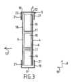
断熱パネルを並べて断熱バリアを構成すると、2つの隣り合う断熱パネル3間にパネル間スペースが存在することとなる。換言すると、パネル間スペース2が、2つの隣り合う断熱パネル3の互いに向かい合う側面を分離する(図7参照)。断熱バリアの断熱の連続性を保証するため、2つの隣り合う断熱パネル3の2つの互いに向かい合う側面を分離するパネル間スペース2に、断熱インサート1が挿入される。図1~3に、かかる断熱インサート1を示す。When the insulating panels are arranged to form an insulating barrier, an inter-panel space exists between two adjacent insulating panels 3. In other words, an
断熱インサート1は、断熱コア4を覆い部材5によって覆ったものを備えている。断熱インサート1は、パネル間スペース2の平行六面体の形状に対応した平行六面体の形状を有し、このパネル間スペース2の形状が断熱インサート1の形状を決定する。よって、断熱インサート1は、互いに平行な2つの平面状の大面6を有する。これら2つの平面状の大面6は、断熱インサート1の長さ方向7と当該断熱インサート1の幅方向8とを定める。断熱インサート1の厚さ方向10に延在する端面9が、両大面6の辺を接続する。The insulating
断熱コア4は、ガラスウールから作製された中央部分11を有する。使用されるガラスウールは積層ガラスウールである。すなわち、本製造方法により、肉眼で視認可能となるように絡み合った(entrelacees)複数の平行なシートを積層方向12に重ねたものから作製されたガラスウールのマットが得られる。換言すると、繊維は主に積層方向12に対して垂直な平面内に配向される。The insulating
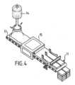
かかる積層ガラスウールは例えば、図4に概略的に示されている水平方向のコンベアベルト13を用いた製法により得ることができる。かかる製法では、砂粒状ガラスを例えば1300~1500℃等の温度の炉14内で溶融する。その後、高速回転を利用した紡績により、この溶融した砂粒状ガラスを繊維に変換する。この繊維にバインダを添加し、これにより得られたものを水平方向のコンベアベルト13に載せて、バインダを重合するための重合炉15に通す。この場合、繊維はコンベアベルト13に対して略平行である。積層は重力の作用の結果として生じるので、積層方向は上記の製造ツールにおける鉛直方向と一致することとなる。積層ガラスウールを作製するための他の製法も可能である。Such laminated glass wool can be obtained, for example, by a process using a
図1~3に示されている実施形態では、コア4のガラスウールの密度は22又は35又は40kg/m3である。 In the embodiment shown in figures 1 to 3, the density of the glass wool of the
本実施形態では、コア4の全部が、ガラスウールを方向12に積層した中央部分11から成る。コア4は、セパレータ17により分割された複数のガラスウール区画16を有する。このセパレータ17は、断熱インサート1の幅方向8に対して垂直に延在する。セパレータ17は断熱インサート1の全長7にわたって延在すると共に、断熱インサート1の全厚10を貫通する。セパレータ17は有利には、当該セパレータ17によって分割されたガラスウール区画16に接合される。In this embodiment, the
このように、図1に示されているコア4は、3つのセパレータ17によって断熱インサート1の幅方向8に分割された4つのガラスウール区画16を有する。図1はセパレータの数に関して好適な一解決手段、すなわち、温度勾配が100℃超の場合に対流を生じさせないための最小のセパレータ数を示している。図3は、コア4が2つのセパレータ17により断熱インサート1の幅方向8に分割された3つの区画16を有する一変形形態を示している。Thus, the
ガラスウールはコア4において、当該ガラスウールの積層方向12が断熱インサート1の幅8に対して垂直となるように配置される。換言すると、ガラスウールを作製する繊維のシートは、断熱インサート1の幅方向8に対して実質的に平行に配置される。The glass wool is arranged in the
好適には、ガラスウールはコア4において、断熱インサート1の厚さ方向10に対して平行な積層方向12で配置される。すなわち、ガラスウールの繊維のシートは、断熱インサート1の大面6に対して実質的に平行である。換言すると、ガラスウールを構成する繊維のシートは、断熱インサート1の幅方向8と長さ方向7とに対して実質的に平行に配置される。図13に示されている代替的な一実施形態では、断熱コアは中央部分11の長手方向端部のうち少なくとも1つに、積層ガラスウールにより作製された端部分50を有する。この端部分は、中央部分11のガラスウールと同じ手法を用いて作製され、端部分もまた、繊維の複数のシートを重ねたものから作製されるが、その積層方向は中央部分11のガラスウールの積層方向とは異なり、断熱インサート1の長さ方向7に対して平行である。かかる端部分により、2つの断熱パネル3間に端から端まで配置される複数の断熱インサート1を完璧に連続して取り付けられるように、断熱コアに良好な長手方向圧縮性を与えることができる。端部分50は例えば、当該端部分50の積層方向における寸法すなわち断熱インサート1の長さに沿った寸法を1cmとすることができる。断熱インサート1の長さ方向において端部分50の構造により圧縮性が付与されるので、端部分50から排気を行ったときの当該端部分50の上記の寸法は、5mmにまで減少することができる。Advantageously, the glass wool is arranged in the
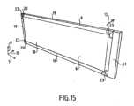
図15に示されている他の代替的な一実施形態では、断熱インサート1は、第1の実施形態に記載されたような積層ガラスウールの中央部分11のみから成ると共に覆い部材5によって覆われた断熱コアを有し、断熱コアはまた、その長手方向端部のうち少なくとも1つに、覆い部材5の外部に配置されたエンドピース51を備えている。このエンドピース51は積層ガラスウールから作製されており、上記にて述べた端部分51と同一の技術的構成を有する。さらに、エンドピース51のガラスウールの密度は20又は35又は40kg/m3である。 In another alternative embodiment shown in figure 15, the insulating
図1に示されているように、覆い部材5は複数の覆い部材部分を有する。具体的には、覆い部材5は平面状覆い部材部分18と、直線状端面覆い部材部分19と、コーナ端面覆い部材部分20と、を有する。これらの覆い部材部分18,19,20は、例えば接合等によってコア4に固定されている。As shown in FIG. 1, the
平面状覆い部材部分18はコア4を覆い、断熱インサート1の大面6となる。これらの平面状覆い部材部分18は矩形であり、コア4の大面の寸法と実質的に同一の寸法を有する。The planar
直線状端面覆い部材部分19は、コア4の各対応する端面を覆う矩形の中央部分を有する。この中央部分は、断熱インサート1の各対応する端面9となる。直線状端面覆い部材部分19は、中央部分の各側に折り返し部21を有する。これらの折り返し部21は、中央部分の長辺から延在する。折り返し部21は、各対応する平面状覆い部材部分18の縁部マージンに重なるように各平面状覆い部材部分18に対して平行に延在する。折り返し部21は、平面状覆い部材部分18の上記の縁部マージンに接合されている。換言すると、直線状端面覆い部材部分19は断熱インサート1の端面9となるものであり、また、端面9と大面6との間の縁部コーナ22においてコア4と重なる。The straight end covering
コーナ端面覆い部材部分20は、断熱インサート1の2つの隣り合う端面9となる2つの直線状端面覆い部材部分19と重なるものである。換言すると、かかるコーナ端面覆い部材部分20は、断熱インサート1の2つの端面9がぶつかる接合部においてコア4の縁部と重なる。端面覆い部材部分19の折り返し部21と同様、コーナ端面覆い部材部分20もコーナ折り返し部23を有し、このコーナ折り返し部23は、対応する端面覆い部材部分19の折り返し部21の端部に対して平行に延在して、当該折り返し部21の端部と重なる。コーナ端面覆い部材部分20は、各コーナ端面覆い部材部分20と重なる端面覆い部材部分19に接合される。The corner end
このように、複数の異なる覆い部材部分18,19,20が互いに接合されると共にガラスウールに接合されることにより、コア4を完全に包囲する連続した1つの覆い部材5を構成する。不図示の一実施形態では、頂部及び底部に配される部分18及び19は、1つのクラフト片として作製することができる。他の一実施形態では、覆い部材5はコア4に接合されることなくコア4を完全に包囲する。In this manner, the different
第1の実施形態では、覆い部材5はクラフト紙から作製されている。かかるクラフト紙は低い摩擦係数を提供するので、断熱インサート1をパネル間スペース2に挿入する際に断熱インサート1をパネル間スペース2に滑り込ませることができる。さらに、上述のクラフト紙の熱収縮係数は5~20×10-6/Kである。これにより、上述のクラフト紙の熱収縮係数は、パネル間スペース内に配される断熱コア4の熱収縮係数と同等になる。これにより、低温に移行する際の断熱インサート1の挙動が均一となる。具体的には、断熱コア4は、覆い部材5の熱収縮に関連する圧縮の作用下で変形するおそれが無くなる。特に、断熱コア4が上述の圧縮の作用下で変形して波状の形状をとり、この波状の形状により対流を促進して断熱バリアの断熱特性を決定付ける空隙をパネル間スペース2に生じさせるおそれが無くなる。 In the first embodiment, the covering
断熱インサート1をパネル間スペースに挿入している際に覆い部材5が破けるリスクを回避するためには、覆い部材5のクラフト紙の坪量を60g/m2超とする。さらに、圧縮時に断熱インサート1の変形を許容するために十分な可撓性を覆い部材5が保持するためには、クラフト紙の坪量を150g/m2未満とし、好適には70~100g/m2とする。 In order to avoid any risk of tearing of the
代替的な一実施形態では、覆い部材5のうち全部又は特定の部分、例えば平面状覆い部材部分18等が、例えばガラス及びバサルト繊維等の鉱物繊維の布又はマットと、ポリマーマトリクスと、から作製された複合材料のシートである。適当である場合には、覆い部材5の他の部分、例えば端面部分19,20は、第1の実施形態にて説明した覆い部材に使用される紙と同一の特性を有するクラフト紙から作製することができる。端面部分19,20に使用されるクラフト紙は、接着材とすることができる。In an alternative embodiment, all or certain portions of the covering
上述のような複合材料は、湿気に対する感受性が低いため、クラフト紙より良好な寸法安定性を有する。その上、ポリマーマトリクスの他にさらに鉱物繊維の布又はマットを用いることにより、ガラスウールの熱収縮係数と同等の熱収縮係数を得ることができるので、低温に移行する際の断熱インサート1の挙動が均一となる。具体的には、覆い部材がポリマー材料のみから作製されている場合、タンクの壁に温度変動が生じ、特にその温度勾配が100℃超の高い値に達するような際には、覆い部材の寸法変動がガラスウールより遥かに大きくなるおそれがあるが、本実施形態では、ガラスウールの熱収縮係数との差が5×10⁻⁶ K―1未満の熱収縮係数を有するガラス繊維の布又はマットを選定することができる。これにより本実施形態では、断熱コアの中央部分11のガラスウールの熱収縮係数がその測定方向において5×10⁻⁶ K-1~8×10⁻⁶ K-1であるところ、平面状覆い部材部分18を作製する複合材料を作製するために用いられる鉱物繊維布は例えば、長さ方向において10-5 K-1のオーダの熱収縮係数を有する。 The composite material as described above has a better dimensional stability than kraft paper, due to its low sensitivity to moisture. Moreover, by using a mineral fiber cloth or mat in addition to the polymer matrix, a thermal contraction coefficient similar to that of glass wool can be obtained, so that the behavior of the insulating
以下の2例では、ポリマーマトリクスを複合シート中に導入することができる。第1の例は、ガラス又はバサルト繊維の布にポリマーマトリクスを含浸又はコーティングする、というものである。このポリマーマトリクスは、溶媒和接着材、ポリウレタン、シリコーン、ゴム又はエポキシド等の中から選択される。好適には、複合シートの面密度は50~400g/m2、厚さは25~500μmである。 The polymer matrix can be introduced into the composite sheet in two ways: In the first example, a glass or basalt fiber cloth is impregnated or coated with a polymer matrix, which is selected from among solvating adhesives, polyurethanes, silicones, rubbers or epoxides, etc. The composite sheet preferably has an areal density of 50-400 g/m2 and a thickness of 25-500 μm.
第2の例は、ガラス又はバサルト繊維の布にポリマーのシートを接合して覆う、というものであり、この接合は例えば、スポットボンディング法又は溶解ボンディング法等を用いて行われる。このポリマーシートは、ポリエチレン、ポリプロピレン、ポリエチレンテレフタレート及びポリ塩化ビニルから選択されたプラスチック樹脂とすることができる。ポリマーマトリクスの乾燥後の密度は、例えば0.8~1.4である。ポリマーのシートの厚さは25~50μmであり、これは、例えば20~40g/m2等の面密度に相当する。 A second example is a glass or basalt fibre cloth covered with a polymer sheet bonded, for example by spot bonding or melt bonding. The polymer sheet can be a plastic resin selected from polyethylene, polypropylene, polyethylene terephthalate and polyvinyl chloride. The dry density of the polymer matrix is for example 0.8-1.4. The thickness of the polymer sheet is 25-50 μm, which corresponds to an areal density of for example 20-40 g/m2 .
他の一実施形態では、覆い部材の全部又は特定の部分、例えば平面状覆い部材部分18が、例えばガラス及びバサルト繊維等の鉱物繊維の布又はマットを紙のシートに接合したものから作製された複合材料のシートである。In another embodiment, all or a particular portion of the covering member, e.g., the planar
図16に示されている他の一実施形態では、平面状覆い部材部分18は、例えばガラス及びバサルト繊維等の鉱物繊維の布又はマットとポリマーマトリクスとを含む複合材料のシートである。かかる複合シートは、その外面すなわち断熱パネル側の面において、紙のシート52により覆われる。本実施形態では、複合シートを覆う紙のシート52は、平面状覆い部材部分18を構成する複合シートに接合され、折り返し部21の内面も紙のシート52に接合される。In another embodiment shown in FIG. 16, the planar
下記にて説明する方法を用いて断熱インサート1をパネル間スペースに挿入できるようにするためには、相対的な流体密で十分である。ここで記載されている複合シートは、適切な場合にはさらにポリマー又は紙のシートにより覆われているが、この複合シートにより上述の相対的な流体密を達成することができる。Relative fluid tightness is sufficient to allow the insulating
他の代替的な一実施形態では、平面状覆い部材部分18は複合材料から作製されると共に、端面覆い部材部分19,20は接着テープから作製される。かかる構成により、湿気に対する寸法安定性と、覆い部材の流体密とを、一層改善することができる。In another alternative embodiment, the
以下、図5~7を参照して、断熱インサート1をパネル間スペースに挿入する方法を説明する。The method of inserting the insulating
まず、上記にて図1~3を参照して説明した構造を有する断熱インサート1を準備する。この断熱インサート1はパネル間スペース2に対して補完的な形状であり、典型的には上述のような平行六面体の形状である。First, prepare an insulating
本挿入方法は吸引システムを使用する。この吸引システムは、以下の説明ではあくまで例示として、図6及び図7に示されている真空ポンプ24である。不図示の一実施形態では、吸引システムはベンチュリ方式を利用した真空発生器である。上記の真空ポンプ24は、ポンピングホース26を介して吸引ノズル25に接続されている。吸引ノズル25は、平面円形状のフランジ27を有する。吸引ノズル25は、ポンピングホース26とは反対側の端部が覆い部材5を穿孔可能な円錐台形状となっている。これにより吸引ノズル25、特にその穿孔端部は、覆い部材5を穿孔して断熱インサート1に挿入される。このように覆い部材5を穿孔することで、断熱インサート1に吸引開口28が形成される。The insertion method uses a suction system. This suction system is a
吸引ノズル25は、密閉断熱タンクの内部を向いて配される端面9から覆い部材5に通されて断熱インサート1に挿入される。The
好適には、吸引ノズル25は、中央部分11のガラスウールの積層方向12に対して垂直な端面9から断熱インサート1に挿入される。Preferably, the
また、吸引ノズル25は、フランジ27が覆い部材5に当接するまで断熱インサート1に挿入される。The
吸引ノズル25が断熱インサート1に挿入完了して適正に位置決めされた後、すなわちフランジ27が覆い部材5に当接した後、真空ポンプ24を作動させて断熱インサート1内に真空圧を発生させる。After the
有利には、例えばクラフト紙、又は鉱物繊維の布若しくはマットとポリマーマトリクスとから作製された複合材料等、覆い部材5を作製する材料が多孔質であるにもかかわらず、また、異なる複数の覆い部材部分18,19,20間の連結部が接合されているにもかかわらず、覆い部材5は上記の真空圧を発生させるために十分な流体密を示すものである。このような相対的な流体密により、真空ポンプ24のポンピング流量は覆い部材5内に真空圧を生じさせるために十分な流量となる。さらに、フランジ27が覆い部材5に押し付けられることで、吸引ノズル25を通した開口28における覆い部材5からの漏れ流量も抑えられる。このようにして、覆い部材5の漏れ流量は真空ポンプ24のポンピング流量より低くなり、真空ポンプ24によって生じる吸引が断熱インサート1内に真空圧を生じさせる。換言すると、材料が多孔質であること、場合によっては、異なる覆い部材部分18,19,20間の連結部の接合が不完全であることに起因して生じる覆い部材のヘッドロスと、吸引ノズル25を挿入するために覆い部材に設けられた開口28に起因して生じ得る全ての漏れとが、真空ポンプ24とその吸引ノズル25とにより生じるヘッドロスより小さいということであり、これにより断熱インサート1内に真空圧を生じさせることができる。Advantageously, despite the porous nature of the material from which the
真空ポンプ24により生じる吸引の吸引流量は8~30m3/hである。好適にはポンピング流量は15m3/hであり、真空ポンプ24のかかるポンピング流量により、過度に多い吸引流量によりクラフト紙覆い部材5が損傷するおそれが生じることなく、断熱インサート1に真空圧を生じさせることができる。 The suction flow rate of the suction generated by the
好適には、真空ポンプ24は、当該真空ポンプ24により引き込まれる可能性のあるあらゆるガラスウール繊維や塵埃を中央部分11からフィルタリング除去するためのフィルタを備えている。Preferably, the
また、真空ポンプにより生じる吸引は有利には、断熱インサート1における中央部分11のガラスウールの積層方向12に対して平行な端面9に位置する面に吸引ノズル25を挿入することによって促進される。具体的には、断熱インサート1の端面9に位置する上述の面から吸引ノズル25を挿入することにより、中央部分11のガラスウールを構成する繊維の複数のシートの積層に関連するヘッドロスを生じることなく、吸引を行うことが可能になる。The suction produced by the vacuum pump is advantageously facilitated by inserting a
また、中央部分11のガラスウールの積層方向12を断熱インサート1の厚さ方向10に対して平行とする配置により、真空圧によって断熱インサート1をこの厚さ方向10に、より圧縮しやすくすることができる。好適な一実施形態では、断熱インサート1の長さ方向において積層されたガラスウールの1つ又は複数の端部分50により、断熱インサート1の長手方向圧縮もより行いやすくなる。Also, by arranging the glass
コア4内にセパレータ17が存在することにより、断熱インサート1がより高剛性となって断熱インサート1の圧縮が均一になる。The presence of the
断熱インサート1内に生じた真空圧によってガラスウールが圧縮され、ひいては断熱インサート1が圧縮される。ガラスウール1のこのような圧縮により、断熱インサート1の厚さを低減することができる。典型的には、断熱インサート1の寸法は、無拘束状態すなわち無圧縮時の厚さがパネル間スペース2の幅以上になり、圧縮状態の厚さがパネル間スペース2の幅未満となるような寸法とされる。例えば、パネル間スペース2が33mm~27mmである場合、断熱インサート1の寸法は、初期厚さすなわち無拘束状態の厚さが35mmであり、圧縮状態の厚さが25mmとなるような寸法とされる。The vacuum pressure created within the insulating
その後、断熱インサート1を断熱バリアの2つの隣り合う断熱パネル3間のパネル間スペース2に挿入する。図7中矢印29により示されているように、断熱インサート1は、パネル間スペース2を画定する隣り合った断熱パネル3の側面に対して大面6が平行となるようにパネル間スペース2に挿入される。この挿入を行っている間、断熱インサート1を圧縮状態に維持するため、吸引ノズル25が断熱インサート1内に留められて真空ポンプ27が断熱インサート1内に真空圧を発生し続ける。断熱インサート1を圧縮状態に維持することにより、断熱インサート1の厚さはパネル間スペース2の幅より小さいので、断熱インサート1をパネル間スペース2に挿入することがより容易になる。The insulating
パネル間スペース2への断熱インサート1の挿入は、吸引ノズル25を通す端面9をタンクの内部に向けるように行われる。これにより、断熱インサート1と吸引ノズル25とにより構成されるアセンブリがより扱いやすくなる。また、パネル間スペース2への断熱インサート1の挿入は有利には、パネル間スペース2の幅に対して平行な積層方向12で行われる。また、セパレータ17は有利には、断熱パネル3により形成された支持面30に対して平行になるように断熱インサート1内に配置される。図7では上述の断熱パネル3は、支持面30を形成する合板のシート32によってポリウレタン発泡体31のブロックを覆ったものを有する。上述のようにセパレータ17を配置することにより、タンク壁内において中央部分11のガラスウールを通る対流が抑えられる。The insulating
パネル間スペース2内に断熱インサート1が適正に配置された後、断熱インサート1から吸引ノズル25を取り出す。この時点から、覆い部材5の内部が開口28を介して外部周辺と連通する。この連通によって断熱インサート1内には真空圧が維持されなくなるので、圧縮拘束が無い状態でガラスウールが膨張可能となる。ガラスウールのこの膨張により、断熱インサート1の厚さが増大して断熱インサート1はパネル間スペース2を完全に埋め、これにより断熱バリアの断熱の良好な連続性が保証される。After the insulating
図11及び図12に示されている実施形態では、パネル間スペース2に断熱インサート1を挿入する際に案内ツールとして剛性の案内システムを使用することができる。In the embodiment shown in Figures 11 and 12, a rigid guide system can be used as a guide tool when inserting the insulating
かかる案内システムは、第1の剛性プレート33と第2の剛性プレート37とを備えている。これら2つの剛性プレート33,37はそれぞれL字形の断面となっており、このL字は矩形の大面38と、当該大面38に対して垂直に延在する折り返し部39と、により形成される。The guiding system includes a first
大面38は断熱インサート1の平面状の大面6の寸法と同様の寸法となっている。The
第1のプレート33の折り返し部39の内面に取っ手40が設けられている。この取っ手は多かれ少なかれ当該折り返し部39の長手方向における中心に配されている。A handle 40 is provided on the inner surface of the folded portion 39 of the
第2のプレート37の折り返し部39は、2つのプレート33,37を図11のように組み立てたときに取っ手40を受けることが可能な切欠きを有する。第2のプレート37の折り返し部39の内面には、2つの取っ手41が設けられている。これらの取っ手41は、第1のプレート33の取っ手40を受容可能な切欠きの各側に配置されている。The folded portion 39 of the
剛性プレート33,37を用いてパネル間スペース2に断熱インサート1を挿入するためには、断熱インサート1を2つの剛性プレート33,37間に挿入する。具体的には、剛性プレート33,37の大面38間に断熱インサート1の大面6を挟んで圧縮する。剛性プレートの折り返し部39は、図12に示されているようにタンク壁の厚さ方向に重ね合わされる。この重ね合わせは、取っ手40を受容するために第2の剛性プレート37の折り返し部39に設けられた切欠きに取っ手40を入れることにより可能になる。To insert the insulating
このようにして、断熱インサート1を圧縮状態で挟み込んで保持する剛性プレート33,37を断熱インサート1と共にパネル間スペース2に挿入することができる。断熱インサート1がパネル間スペース2に挿入完了した後は、取っ手40,41を用いて剛性プレートを引き出すことができ、これにより断熱インサート1が圧縮状態から解放されて膨張し、パネル間スペース2を埋めることができるようになる。In this way, the
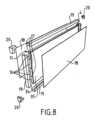
図8は、断熱インサート1の一変形形態を示す。この第1の変形形態では、上記にて図1~3を参照して説明したものと同一要素又は同一の機能を果たす要素には、同一の符号を付している。Figure 8 shows one variant of the insulating
この第1の変形形態が図1~3に示す断熱インサート1と相違する点は、断熱コア4の中央部分11が、断熱インサート1の厚さ方向に重なった2つの断熱層を有することである。This first variant differs from the insulating
第1の断熱層34は、上記にて図1~3を参照して説明したコアの構造と類似する構造を有する。すなわち、積層ガラスウールの中央部分11をクラフト紙製のセパレータ17により分割した複数の区画16を有する構造となっている。これらの積層ガラスウール区画16のガラスウール積層方向は、断熱パネル3によって形成された支持面30に対して平行であり、好適にはパネル間スペース2の幅に対して平行、すなわち断熱インサート1の厚さ方向10に対して平行である。The first insulating
第2の断熱層35は、積層ガラスウールの層を1つのみ有する。この第2の層35を構成する積層ガラスウールの積層方向は、断熱パネル3によって形成された支持面30に対して平行であり、好適には断熱インサート1の厚さ方向10に対して平行である。The
第1の断熱層34と第2の断熱層35とは分離層36によって分離されている。この分離層36は、例えばガラス繊維又はクラフト紙から作製される。長さ方向及び幅方向における断熱インサート1の圧縮性を改善するために好適なのは、これら2つの次元において分離層36を、図14に一部示すように短くすることである。 The first and second insulating
第1の断熱層34は、第2の断熱層35の積層ガラスウールの密度より高い密度の積層ガラスウールを有する。例えば、第1の断熱層34の積層ガラスウールの密度は35~40kg/m3であり、第2の断熱層35の積層ガラスウールの密度は22kg/m3である。 The
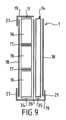
図9は、断熱インサート1の第2の変形形態を示す。この第2の変形形態では、上記にて図1~3を参照して説明したものと同一要素又は同一の機能を果たす要素には、同一の符号を付している。Figure 9 shows a second variant of the insulating
第2の変形形態が図8に示す第1の変形形態と相違する点は、覆い部材5が断熱コア4を完全には覆っていないことである。具体的には図9では、第2の断熱層35が断熱インサート1の端面9において覆われていない。換言すると、直線状端面覆い部材部分19のうち1つは第1の断熱層34のみを覆うと共に、折り返し部21を1つのみ有し、この折り返し部21は、第1の断熱層34を覆う平面状の覆い部材部分18に接合されている。The second variant differs from the first variant shown in FIG. 8 in that the covering
図8及び図9に示されている変形形態の断熱インサート1は、第2の断熱層35のおかげで良好な膨張圧縮能力を提供しつつ、第1の断熱層34のおかげで均一に変形して積層ガラスウールを通る対流を抑えることができるために十分な剛性を維持する。これにより、上述のような断熱インサート1は圧縮変形しやすくなってパネル間スペース2に挿入しやすくなると同時に、圧縮が維持されなくなったときにはパネル間スペース2を完全に埋めて、断熱バリア内における対流を回避することができる。かかる圧縮は、図8に示されたような断熱コア4を覆い部材5が完全に覆う断熱インサート1の場合には、真空ポンプ24等の吸引システムを用いることにより達成することができ、これにより、真空圧の作用下で圧縮するために十分な流体密が提供される。この圧縮はまた、断熱コア4を覆い部材5が完全には覆わない図9に示されている断熱インサートの場合には、吸引システムを用いずに達成することができる。The modified insulating
密閉断熱タンクを作製するための上述の技術は、種々の種類の貯蔵部において使用することができ、例えば、沿岸設備又はメタン運搬船等の浮体構造物等においてLNG貯蔵部の二次断熱バリア及び/又は一次断熱バリアを構成するために上述の技術を使用することができる。The techniques described above for creating sealed insulated tanks can be used in various types of storage, for example, the techniques described above can be used to provide secondary and/or primary insulating barriers for LNG storage in coastal facilities or floating structures such as methane carriers.
図10を参照すると、メタン運搬船70の抜粋図が、船舶の二重船殻72内に設置された全体形状が角柱形の密閉断熱タンク71を示している。タンク71の壁は、当該タンクに入ったLNGと接触する一次密閉バリアと、当該一次密閉バリアと船舶の二重船殻72との間に配置された二次密閉バリアと、一次密閉バリアと二次密閉バリアとの間及び二次密閉バリアと二重船殻72との間にそれぞれ配置された2つの断熱バリアと、を備えている。Referring to FIG. 10, an excerpt of a
自明の通り、タンク71から又はタンク71へLNGの貨物を移送するため、船舶の上甲板に配置された荷役パイプライン73を海上又は港湾ターミナルに、適切な接続部を介して連結することができる。As will be appreciated, a
図10は海上ターミナルの一例を示しており、この海上ターミナルは荷役ステーション75と、海中パイプ76と、沿岸設備77と、を備えている。荷役ステーション75は定置の沖合設備であり、可動アーム74と、当該可動アーム74を支持するタワー78と、を備えている。可動アーム74は断熱可撓性ホース79の束を支持し、この断熱可撓性ホース79は荷役パイプライン73に接続可能なものである。方向調整可能なこの可動アーム74は、あらゆるサイズのメタン運搬船に適合することができる。タワー78内部には、不図示の接続パイプが延設されている。荷役ステーション75は、メタン運搬船70から沿岸設備77へ又は沿岸設備77からメタン運搬船70への荷役作業を行えるものである。沿岸設備77は、液化ガス貯蔵タンク80と、海中パイプ76によって荷役ステーション75に接続された接続パイプ81と、を備えている。海中パイプ76は、荷役ステーション75と沿岸設備77との間の例えば5km等の長い距離にわたって液化ガスを移送するためのものであり、これにより、荷役作業中もメタン運搬船70を海岸から遠距離に停泊させ続けることができる。10 shows an example of a marine terminal, which includes a
液化ガスを移送するために必要な圧力を発生するためには、船舶70に搭載されたポンプ及び/又は沿岸設備77に備え付けられたポンプ及び/又は荷役ステーション75に備え付けられたポンプを使用する。To generate the pressure required to transport the liquefied gas, pumps on board the
複数の特定の実施形態を参照して本発明を説明したが、これらの実施形態に限定されないことは極めて明らかであり、本発明は、特許請求の範囲により定まる発明の範囲に属する限りにおいて、上記にて説明した手段の全ての技術的均等手段及びその全ての組み合わせを包含する。Although the present invention has been described with reference to several specific embodiments, it is quite clear that the present invention is not limited to these embodiments, and the present invention encompasses all technical equivalents of the above-described means and all combinations thereof, insofar as they fall within the scope of the invention as defined by the claims.
「備える」又は「有する」等の動詞及びその活用形を用いた場合、これは、請求項に記載された要素又はステップ以外の要素又はステップの存在を除外するものではない。The use of verbs such as "comprise" or "have" and their conjugations does not exclude the presence of elements or steps other than those stated in a claim.
特許請求の範囲において、括弧書きのいかなる符号も、請求項を限定するものと解すべきものではない。In the claims, any reference signs in parentheses shall not be construed as limiting the claims.
Claims (27)
Translated fromJapanese前記断熱バリアは、規則的なパターンで並べられた複数の断熱パネル(3)を備えており、
2つの隣り合う前記断熱パネル(3)の互いに向かい合う側面が、当該2つの隣り合う断熱パネル(3)を分離するパネル間スペース(2)を画定し、
前記密閉断熱タンク壁は、前記パネル間スペース(2)を埋めるように前記パネル間スペース(2)内に配置された断熱インサート(1)をさらに備えており、
前記断熱インサート(1)は、少なくとも部分的に覆い部材(5)によって覆われた断熱コア(4)を備えており、
前記断熱コア(4)の少なくとも中央部分(11)は積層ガラスウールを備えており、
前記積層ガラスウールは、繊維の複数のシートを積層方向(12)に重ねたものを有し、
前記断熱インサート(1)は、前記中央部分の前記積層方向(12)が、前記パネル間スペース(2)内で前記互いに向かい合う側面の離隔方向である前記パネル間スペース(2)の幅方向に対して平行になるように、前記パネル間スペース(2)内に配置されており、
前記断熱コアの長さ方向は前記パネル間スペースの長さ方向に延在し、
前記断熱コアは、前記中央部分(11)の長手方向端部のうち少なくとも1つに、積層ガラスウールを有する少なくとも1つの端部分(50)を有し、
前記端部分は、前記断熱インサートの長さ方向(7)に対して平行な積層方向に繊維の複数のシートを重ねたものを含む
ことを特徴とする密閉断熱タンク壁。 A sealed, insulated tank wall comprising an insulating barrier defining a planar support surface (30) and a sealing membrane provided on the planar support surface (30) of the insulating barrier,
The thermal barrier comprises a plurality of thermal insulation panels (3) arranged in a regular pattern,
the opposing sides of two adjacent insulation panels (3) define an inter-panel space (2) separating the two adjacent insulation panels (3);
The sealed insulated tank wall further comprises an insulating insert (1) disposed within the inter-panel space (2) so as to fill the inter-panel space (2);
The insulating insert (1) comprises an insulating core (4) at least partially covered by a covering member (5),
At least a central portion (11) of the insulating core (4) comprises laminated glass wool;
The laminated glass wool comprises a plurality of sheets of fibers stacked in a stacking direction (12),
The insulating insert (1) is arranged in the inter-panel space (2) such that the stacking direction (12) of the central portion is parallel to a width direction of the inter-panel space (2), which is a separation direction of the opposing side surfaces in the inter-panel space (2);
the length of the insulating core extends along the length of the inter-panel space;
The insulating core has at least one end portion (50) with laminating glass wool at at least one of the longitudinal ends of the central portion (11),
The end portion comprises multiple sheets of fabric stacked together in a stacking direction parallel to the length (7) of the insulating insert.
A sealed insulated tank wall.
前記断熱バリアは、規則的なパターンで並べられた複数の断熱パネル(3)を備えており、
2つの隣り合う前記断熱パネル(3)の互いに向かい合う側面が、当該2つの隣り合う断熱パネル(3)を分離するパネル間スペース(2)を画定し、
前記密閉断熱タンク壁は、前記パネル間スペース(2)を埋めるように前記パネル間スペース(2)内に配置された断熱インサート(1)をさらに備えており、
前記断熱インサート(1)は、少なくとも部分的に覆い部材(5)によって覆われた断熱コア(4)を備えており、
前記断熱コア(4)の少なくとも中央部分(11)は積層ガラスウールを備えており、
前記積層ガラスウールは、繊維の複数のシートを積層方向(12)に重ねたものを有し、
前記断熱インサート(1)は、前記中央部分の前記積層方向(12)が、前記パネル間スペース(2)内で前記互いに向かい合う側面の離隔方向である前記パネル間スペース(2)の幅方向に対して平行になるように、前記パネル間スペース(2)内に配置されており、
前記断熱インサートの長さ方向は前記パネル間スペースの長さ方向に延在し、
前記断熱インサートは長手方向端部のうち少なくとも1つに、当該断熱インサートの長さ方向(7)に対して平行な積層方向に繊維の複数のシートを重ねたものを有する積層ガラスウールを含む少なくとも1つのエンドピース(51)を備えており、
前記エンドピースは前記覆い部材(5)によって前記断熱コアから分離している
ことを特徴とする密閉断熱タンク壁。A sealed, insulated tank wall comprising an insulating barrier defining a planar support surface (30) and a sealing membrane provided on the planar support surface (30) of the insulating barrier,
The thermal barrier comprises a plurality of thermal insulation panels (3) arranged in a regular pattern,
the opposing sides of two adjacent insulation panels (3) define an inter-panel space (2) separating the two adjacent insulation panels (3);
The sealed insulated tank wall further comprises an insulating insert (1) disposed within the inter-panel space (2) so as to fill the inter-panel space (2);
The insulating insert (1) comprises an insulating core (4) at least partially covered by a covering member (5),
At least a central portion (11) of the insulating core (4) comprises laminated glass wool;
The laminated glass wool comprises a plurality of sheets of fibers stacked in a stacking direction (12),
The insulating insert (1) is arranged in the inter-panel space (2) such that the stacking direction (12) of the central portion is parallel to a width direction of the inter-panel space (2), which is a separation direction of the opposing side surfaces in the inter-panel space (2);
the length of the insulating insert extends along the length of the interpanel space;
the insulating insert comprises at least one end piece (51) at at least one of its longitudinal ends, the end piece (51) comprising laminated glass wool having a plurality of sheets of fibres superposed in a stacking direction parallel to the length (7) of the insulating insert,
The end pieces are separated from the insulating core by the covering member (5).
Asealed insulated tank wall.
前記セパレータ(17)は、前記中央部分(11)の前記積層ガラスウールを、前記密閉断熱タンク壁の厚さ方向に整列した複数の積層ガラスウール区画(16)に分割する、請求項1又は2記載の密閉断熱タンク壁。 the insulating core (4) comprises at least one separator (17) extending in a plane perpendicular to the thickness of the closed insulated tank wall,
3. The tank wallaccording to claim 1, wherein the separator (17) divides the laminated glass wool in the central portion (11) into a plurality of laminated glass wool sections (16) aligned in the thickness direction of the tank wall.
前記セパレータ(17)は前記密閉断熱タンク壁の厚さ方向に5~20cm離隔している、
請求項3記載の密閉断熱タンク壁。 the insulating core (4) comprises a plurality of separators (17) for dividing the laminated glass wool of the central portion (11) into a plurality of laminated glass wool sections (16) aligned in the thickness direction of the sealed insulating tank wall,
The separators (17) are spaced apart by 5 to 20 cm in the thickness direction of the sealed, insulated tank wall.
4. The sealed, insulated tank wall of claim3 .
請求項1から4までのいずれか1項記載の密閉断熱タンク壁。 The insulating core comprises laminated glass wool having a density of 20 to 45 kg/m3 .
5. A sealed, insulated tank wall according to any one of claims 1 to4 .
前記第1の断熱層(34)と前記第2の断熱層(35)とは、前記パネル間スペース(2)の幅方向において重なり合い、
前記第1の断熱層及び前記第2の断熱層の積層ガラスウールの積層方向は、前記パネル間スペース(2)の幅方向に対して平行であり、
前記第1の断熱層と前記第2の断熱層とは、2つの前記断熱パネルの面に対して平行な分離シート(36)によって分離されている、
請求項1から5までのいずれか1項記載の密閉断熱タンク壁。 the central portion (11) of the insulating core (4) comprises a first insulating layer (34) of laminated glass wool and a second insulating layer (35) of laminated glass wool;
The first insulation layer (34) and the second insulation layer (35) overlap each other in the width direction of the inter-panel space (2),
The lamination direction of the laminated glass wool of the first insulation layer and the second insulation layer is parallel to the width direction of the inter-panel space (2);
The first and second insulation layers are separated by a separation sheet (36) parallel to the faces of the two insulation panels.
6. A hermetically insulating tank wall according to any one of claims 1 to5 .
請求項6記載の密閉断熱タンク壁。 the laminating glass wool (11) of the first insulation layer (34) has a density higher than the density of the laminating glass wool (11) of the second insulation layer (35);
7. The sealed, insulated tank wall of claim6 .
請求項1から7までのいずれか1項記載の密閉断熱タンク壁。 The covering member (5) completely surrounds the insulating core.
A hermetically insulating tank wall according to any one of claims 1 to7 .
前記覆い部材部分(18,19,20)は互いに接合され及び/又は前記断熱コア(4)に接合されている、
請求項1から8までのいずれか1項記載の密閉断熱タンク壁。 The covering member (5) has a plurality of covering member portions (18, 19, 20),
The cover member portions (18, 19, 20) are joined to each other and/or to the insulating core (4).
A hermetically insulating tank wall according to any one of claims 1 to8 .
請求項1から9までのいずれか1項記載の密閉断熱タンク壁。 At least a portion of said covering element (5) comprises a material selected from a polymer sheet, a composite sheet comprising mineral fibres and a polymer matrix, a composite sheet comprising mineral fibres bonded to a paper or polymer sheet, and combinations thereof;
A sealed, insulated tank wall according to any one of claims 1 to9 .
請求項10記載の密閉断熱タンク壁。 the polymeric sheet or composite sheet is bonded to the insulating core by a coating of adhesive disposed between the polymeric sheet or composite sheet and the insulating core;
The sealed, insulated tank wall of claim10 .
請求項1から11までのいずれか1項記載の密閉断熱タンク壁。 The cover member (5) has planar cover member portions (18) on each side of the insulating core that are perpendicular to the width of the inter-panel space.
A sealed, insulated tank wall according to any one of claims 1 to11 .
請求項12記載の密閉断熱タンク壁。 At least one of the planar covering member portions (18) comprises a composite sheet comprising mineral fibers in the form of a fabric or mat and a polymer matrix;
13. The sealed, insulated tank wall of claim12 .
請求項13記載の密閉断熱タンク壁。 The polymer matrix comprises a sheet of polymer covering the mineral fibers on at least one of the two sides of the mineral fiber cloth or mat;
14. The sealed, insulated tank wall of claim13 .
請求項14記載の密閉断熱タンク壁。 The polymer sheet covering the mineral fibers is bonded to the mineral fiber cloth or mat using a hot melt or spot bonding method.
15. The sealed, insulated tank wall of claim14 .
請求項14又は15記載の密閉断熱タンク壁。 The polymeric sheet covering the mineral fiber cloth or mat is made from a resin selected from the group consisting of polyethylene, polypropylene, polyethylene terephthalate and polyvinyl chloride.
16. The sealed, insulated tank wall according to claim14 or15 .
請求項13から16までのいずれか1項記載の密閉断熱タンク壁。 The composite sheet is covered with a polymeric sheet.
A sealed, insulated tank wall according to any one of claims13 to16 .
請求項13から17までのいずれか1項記載の密閉断熱タンク壁。 The composite sheet is covered with a sheet of paper.
18. A sealed, insulated tank wall according to any one of claims13 to17 .
請求項12から18までのいずれか1項記載の密閉断熱タンク壁。 At least one of the planar cover member portions comprises kraft paper.
A sealed, insulated tank wall according to any one of claims12 to18 .
前記端面覆い部材部分は、前記断熱コアの周の全部又は一部に沿って配置されている、請求項12から19までのいずれか1項記載の密閉断熱タンク壁。 The cover member (5) has end cover member portions extending across the width of the inter-panel space between the planar cover member portions (18) located on either side of the insulating core,
20. The tank wall of claim12 , wherein the end wrapper portions are disposed around all or part of the circumference of the insulating core.
請求項20記載の密閉断熱タンク壁。 The end cover member portion includes kraft paper.
21. The sealed, insulated tank wall of claim20 .
請求項20又は21記載の密閉断熱タンク壁。 the end cap portion comprises a sheet of polymer;
22. The sealed, insulated tank wall of claim20 or21 .
請求項1から22までのいずれか1項記載の密閉断熱タンク壁。 The difference between the thermal contraction coefficient of the insulating core (4) and the thermal contraction coefficient of the covering member (5) is 15×10−6 /K or less.
23. A sealed, insulated tank wall according to any one of claims 1 to22 .
請求項1から23までのいずれか1項記載の密閉断熱タンク壁。 the insulating panel of the thermal barrier comprises a block of polyurethane foam;
24. A sealed, insulated tank wall according to any one of claims 1 to23 .
二重船殻(72)と、前記二重船殻内に配置されたタンクと、を備えており、
前記タンクは、請求項1から24までのいずれか1項記載の密閉断熱タンク壁を備えていることを特徴とする船舶(70)。 A vessel (70) for transporting cryogenic liquid products, comprising:
The vessel comprises a double hull (72) and a tank disposed within the double hull,
A ship (70) characterized in that the tank comprises a sealed, insulated tank wall according to any one of claims 1 to24 .
請求項25記載の船舶(70)と、断熱パイプライン(73,79,76,81)と、を備えており、
前記断熱パイプライン(73,79,76,81)は、前記船舶の前記二重船殻内に配置された前記タンク(71)を浮体式又は沿岸貯蔵施設(77)とポンプとに接続するように配置されており、
前記ポンプは、前記断熱パイプラインを介して前記浮体式若しくは沿岸貯蔵施設から前記船舶の前記タンクへ又は前記タンクから前記浮体式若しくは沿岸貯蔵施設へ、低温液体製品の流れを圧送するためのものである
ことを特徴とする移送システム。 1. A transfer system for a cryogenic liquid product, comprising:
A vessel (70) according to claim25 and an insulated pipeline (73, 79, 76, 81),
the insulated pipelines (73, 79, 76, 81) are arranged to connect the tanks (71) arranged in the double hull of the vessel to a floating or onshore storage facility (77) and to a pump;
13. A transfer system comprising: a pump for pumping a flow of cryogenic liquid product through the insulated pipeline from the floating or onshore storage facility to the tank of the vessel or from the tank to the floating or onshore storage facility.
断熱パイプライン(73,79,76,81)を介して浮体式若しくは沿岸貯蔵施設(77)から前記船舶の前記タンク(71)へ又は前記タンク(71)から前記浮体式若しくは沿岸貯蔵施設(77)へ低温液体製品を搬送する
ことを特徴とする方法。 26. A method for loading or unloading a vessel (70) according to claim25 , comprising the steps of:
1. A method for transporting cryogenic liquid product from a floating or onshore storage facility (77) to the tank (71) of the vessel or from the tank (71) to the floating or onshore storage facility (77) via an insulated pipeline (73, 79, 76, 81).
Priority Applications (1)
| Application Number | Priority Date | Filing Date | Title |
|---|---|---|---|
| JP2024157897AJP2024175001A (en) | 2019-08-09 | 2024-09-12 | Sealed insulated tank with inter-panel insulation inserts |
Applications Claiming Priority (1)
| Application Number | Priority Date | Filing Date | Title |
|---|---|---|---|
| PCT/FR2019/000131WO2021028625A1 (en) | 2019-08-09 | 2019-08-09 | Sealed and thermally insulating tank having inter-panel insulating inserts |
Related Child Applications (1)
| Application Number | Title | Priority Date | Filing Date |
|---|---|---|---|
| JP2024157897ADivisionJP2024175001A (en) | 2019-08-09 | 2024-09-12 | Sealed insulated tank with inter-panel insulation inserts |
Publications (2)
| Publication Number | Publication Date |
|---|---|
| JP2022543675A JP2022543675A (en) | 2022-10-13 |
| JP7573599B2true JP7573599B2 (en) | 2024-10-25 |
Family
ID=68062954
Family Applications (2)
| Application Number | Title | Priority Date | Filing Date |
|---|---|---|---|
| JP2022507784AActiveJP7573599B2 (en) | 2019-08-09 | 2019-08-09 | Sealed insulated tank with inter-panel insulation inserts |
| JP2024157897APendingJP2024175001A (en) | 2019-08-09 | 2024-09-12 | Sealed insulated tank with inter-panel insulation inserts |
Family Applications After (1)
| Application Number | Title | Priority Date | Filing Date |
|---|---|---|---|
| JP2024157897APendingJP2024175001A (en) | 2019-08-09 | 2024-09-12 | Sealed insulated tank with inter-panel insulation inserts |
Country Status (6)
| Country | Link |
|---|---|
| US (1) | US12158243B2 (en) |
| EP (1) | EP4010621A1 (en) |
| JP (2) | JP7573599B2 (en) |
| KR (1) | KR20220045968A (en) |
| CN (1) | CN114556010B (en) |
| WO (1) | WO2021028625A1 (en) |
Families Citing this family (2)
| Publication number | Priority date | Publication date | Assignee | Title |
|---|---|---|---|---|
| EP4010622A1 (en)* | 2019-08-09 | 2022-06-15 | Gaztransport Et Technigaz | Method for manufacturing a wall of a sealed and thermally insulating tank having inter-panel insulating inserts |
| FR3152858A1 (en)* | 2023-09-08 | 2025-03-14 | Gaztransport Et Technigaz | Waterproof and thermally insulating tank wall with an insulating seal |
Citations (8)
| Publication number | Priority date | Publication date | Assignee | Title |
|---|---|---|---|---|
| JP2004084293A (en) | 2002-08-27 | 2004-03-18 | Nlm Ecal Co Ltd | Connection structure of panel, connection method for panel, housing box, and assembling method for housing case |
| JP2006137421A (en) | 2004-11-10 | 2006-06-01 | Gaz Transport & Technigaz | Sealed, thermally insulated tank incorporated into the load-bearing structure of ship |
| JP2006527152A (en) | 2003-06-06 | 2006-11-30 | グッドリッチ・コーポレイション | Multilayer fire barrier system |
| JP2014193736A (en) | 2013-03-29 | 2014-10-09 | Air Water Inc | Cold insulation container for air transportation |
| JP2015134931A (en) | 2010-04-16 | 2015-07-27 | アウトラスト テクノロジーズ,リミテッド ライアビリティ カンパニー | Thermal regulating building materials and other construction components containing polymeric phase change materials |
| JP2017515010A (en) | 2014-05-07 | 2017-06-08 | バイアックス ファイバーフィルム | Non woven web |
| JP2018115496A (en) | 2017-01-19 | 2018-07-26 | 旭ファイバーグラス株式会社 | High density thermal insulation panel using inorganic fiber material containing vacuum insulation material |
| WO2019043347A1 (en) | 2017-09-04 | 2019-03-07 | Gaztransport Et Technigaz | Sealed and thermally insulating tank with anti-convective filling element |
Family Cites Families (19)
| Publication number | Priority date | Publication date | Assignee | Title |
|---|---|---|---|---|
| US474753A (en) | 1892-05-10 | Trace-support | ||
| FR2599468B1 (en)* | 1986-06-03 | 1988-08-05 | Technigaz | THERMALLY INSULATING WALL STRUCTURE OF WATERPROOF TANK |
| JP2744694B2 (en)* | 1990-11-28 | 1998-04-28 | 三菱重工業株式会社 | Expandable heat-insulating material for filling gap and method of mounting the same |
| FR2691520B1 (en) | 1992-05-20 | 1994-09-02 | Technigaz Ste Nle | Prefabricated structure for forming watertight and thermally insulating walls for containment of a fluid at very low temperature. |
| FR2724623B1 (en) | 1994-09-20 | 1997-01-10 | Gaztransport Et Technigaz | IMPROVED WATERPROOF AND THERMALLY INSULATING TANK INTEGRATED INTO A CARRIER STRUCTURE |
| KR200189252Y1 (en) | 2000-02-15 | 2000-07-15 | 김옥규 | Heat insulating mat of lng reserve tank for ship |
| KR101260557B1 (en)* | 2010-01-05 | 2013-05-06 | 엘지전자 주식회사 | Vacuum insulation pannel and method for fabricating the same |
| FR2987100B1 (en)* | 2012-02-20 | 2015-04-10 | Gaztransp Et Technigaz | CALORIFYING ELEMENTS FOR SEALED AND THERMALLY INSULATED TANKS |
| FR2987424B1 (en)* | 2012-02-23 | 2016-06-10 | Gaztransport Et Technigaz | INSULATING BOX COMPRISING A SPACE OF FLOW |
| KR101415899B1 (en) | 2012-05-09 | 2014-07-14 | 한국과학기술원 | Cryogenic liquid containment system and cargo containment system for liquefied natural gas carrier using the same |
| FR2996520B1 (en) | 2012-10-09 | 2014-10-24 | Gaztransp Et Technigaz | SEALED AND THERMALLY INSULATING TANK COMPRISING A METALIC MEMBRANE WOUNDED ACCORDING TO ORTHOGONAL PLATES |
| FR3002514B1 (en) | 2013-02-22 | 2016-10-21 | Gaztransport Et Technigaz | METHOD FOR MANUFACTURING A SEALED AND THERMALLY INSULATING BARRIER FOR A STORAGE TANK |
| FR3006662B1 (en)* | 2013-06-07 | 2015-05-29 | Gaztransp Et Technigaz | SELF-CONTAINING BODY FOR THE THERMAL ISOLATION OF A STORAGE TANK FOR A FLUID AND METHOD FOR MANUFACTURING SUCH A BODY |
| FR3019520B1 (en)* | 2014-04-08 | 2016-04-15 | Gaztransport Et Technigaz | WATERPROOF AND THERMALLY INSULATED TANK IN A FLOATING WORK |
| FR3022971B1 (en) | 2014-06-25 | 2017-03-31 | Gaztransport Et Technigaz | SEALED AND INSULATING TANK AND METHOD OF MAKING SAME |
| WO2019043348A1 (en)* | 2017-09-04 | 2019-03-07 | Gaztransport Et Technigaz | Sealed and thermally insulating vessel having an anti-convective filler plate |
| KR20190088708A (en) | 2018-01-19 | 2019-07-29 | 유신단열 주식회사 | glass fiber insulator for natural gas tank |
| FR3077865B1 (en)* | 2018-02-09 | 2020-02-28 | Gaztranport Et Technigaz | WATERPROOF AND THERMALLY INSULATING TANK COMPRISING INTER-PANEL INSULATING CAPS |
| FR3077764B1 (en) | 2018-02-09 | 2020-01-17 | Gaztransport Et Technigaz | PROCESS FOR MANUFACTURING A WATERPROOF AND THERMALLY INSULATING TANK WALL COMPRISING INTER-PANEL INSULATING CAPS |
- 2019
- 2019-08-09JPJP2022507784Apatent/JP7573599B2/enactiveActive
- 2019-08-09EPEP19773884.2Apatent/EP4010621A1/enactivePending
- 2019-08-09USUS17/634,068patent/US12158243B2/enactiveActive
- 2019-08-09CNCN201980100694.7Apatent/CN114556010B/enactiveActive
- 2019-08-09WOPCT/FR2019/000131patent/WO2021028625A1/ennot_activeCeased
- 2019-08-09KRKR1020227007121Apatent/KR20220045968A/ennot_activeCeased
- 2024
- 2024-09-12JPJP2024157897Apatent/JP2024175001A/enactivePending
Patent Citations (8)
| Publication number | Priority date | Publication date | Assignee | Title |
|---|---|---|---|---|
| JP2004084293A (en) | 2002-08-27 | 2004-03-18 | Nlm Ecal Co Ltd | Connection structure of panel, connection method for panel, housing box, and assembling method for housing case |
| JP2006527152A (en) | 2003-06-06 | 2006-11-30 | グッドリッチ・コーポレイション | Multilayer fire barrier system |
| JP2006137421A (en) | 2004-11-10 | 2006-06-01 | Gaz Transport & Technigaz | Sealed, thermally insulated tank incorporated into the load-bearing structure of ship |
| JP2015134931A (en) | 2010-04-16 | 2015-07-27 | アウトラスト テクノロジーズ,リミテッド ライアビリティ カンパニー | Thermal regulating building materials and other construction components containing polymeric phase change materials |
| JP2014193736A (en) | 2013-03-29 | 2014-10-09 | Air Water Inc | Cold insulation container for air transportation |
| JP2017515010A (en) | 2014-05-07 | 2017-06-08 | バイアックス ファイバーフィルム | Non woven web |
| JP2018115496A (en) | 2017-01-19 | 2018-07-26 | 旭ファイバーグラス株式会社 | High density thermal insulation panel using inorganic fiber material containing vacuum insulation material |
| WO2019043347A1 (en) | 2017-09-04 | 2019-03-07 | Gaztransport Et Technigaz | Sealed and thermally insulating tank with anti-convective filling element |
Also Published As
| Publication number | Publication date |
|---|---|
| WO2021028625A1 (en) | 2021-02-18 |
| JP2022543675A (en) | 2022-10-13 |
| EP4010621A1 (en) | 2022-06-15 |
| CN114556010B (en) | 2023-08-25 |
| US20220349523A1 (en) | 2022-11-03 |
| US12158243B2 (en) | 2024-12-03 |
| CN114556010A (en) | 2022-05-27 |
| JP2024175001A (en) | 2024-12-17 |
| KR20220045968A (en) | 2022-04-13 |
Similar Documents
| Publication | Publication Date | Title |
|---|---|---|
| JP7329132B2 (en) | Method for manufacturing closed insulated tank walls with inter-panel insulation inserts | |
| CN111788427B (en) | Sealed heat-insulating tank containing inter-plate insulating plug | |
| JP2024175001A (en) | Sealed insulated tank with inter-panel insulation inserts | |
| KR102120579B1 (en) | Method for manufacturing a sealed and thermally insulating tank wall comprising inter panel insulating plugs | |
| KR102583479B1 (en) | Sealed and insulated tank with anti-convection covering strips | |
| KR102558940B1 (en) | Sealed and insulated tank with anti-convection filler elements | |
| AU2015226021B2 (en) | Sealed and insulating vessel comprising a deflection element allowing the flow of gas at a corner | |
| CN114746690B (en) | Sealed and insulated tanks, systems and vessels and methods of loading or unloading same | |
| KR20220092431A (en) | Sealed and thermally insulating tank comprising a bridging element | |
| CN112797311B (en) | Sealed and thermally insulated can | |
| JP7463361B2 (en) | Sealed insulated tank | |
| RU2790748C1 (en) | Method for manufacturing wall of hermetic and heat-insulating tank with inter-panel insulation inserts | |
| RU2788882C1 (en) | Sealed and thermally insulated tank with inter-panel insulation inserts | |
| RU2771636C2 (en) | Sealed heat insulation tank including inter-panel insulation plugs | |
| RU2812078C1 (en) | Sealed and heat-insulating tank with anti-convection insulation seals |
Legal Events
| Date | Code | Title | Description |
|---|---|---|---|
| A621 | Written request for application examination | Free format text:JAPANESE INTERMEDIATE CODE: A621 Effective date:20220411 | |
| A977 | Report on retrieval | Free format text:JAPANESE INTERMEDIATE CODE: A971007 Effective date:20230227 | |
| A131 | Notification of reasons for refusal | Free format text:JAPANESE INTERMEDIATE CODE: A131 Effective date:20230328 | |
| A521 | Request for written amendment filed | Free format text:JAPANESE INTERMEDIATE CODE: A523 Effective date:20230606 | |
| A131 | Notification of reasons for refusal | Free format text:JAPANESE INTERMEDIATE CODE: A131 Effective date:20231003 | |
| A521 | Request for written amendment filed | Free format text:JAPANESE INTERMEDIATE CODE: A523 Effective date:20231225 | |
| RD03 | Notification of appointment of power of attorney | Free format text:JAPANESE INTERMEDIATE CODE: A7423 Effective date:20240315 | |
| A131 | Notification of reasons for refusal | Free format text:JAPANESE INTERMEDIATE CODE: A131 Effective date:20240409 | |
| A601 | Written request for extension of time | Free format text:JAPANESE INTERMEDIATE CODE: A601 Effective date:20240704 | |
| A601 | Written request for extension of time | Free format text:JAPANESE INTERMEDIATE CODE: A601 Effective date:20240909 | |
| A521 | Request for written amendment filed | Free format text:JAPANESE INTERMEDIATE CODE: A523 Effective date:20240912 | |
| TRDD | Decision of grant or rejection written | ||
| A01 | Written decision to grant a patent or to grant a registration (utility model) | Free format text:JAPANESE INTERMEDIATE CODE: A01 Effective date:20241001 | |
| A521 | Request for written amendment filed | Free format text:JAPANESE INTERMEDIATE CODE: A821 Effective date:20240913 | |
| A61 | First payment of annual fees (during grant procedure) | Free format text:JAPANESE INTERMEDIATE CODE: A61 Effective date:20241015 | |
| R150 | Certificate of patent or registration of utility model | Ref document number:7573599 Country of ref document:JP Free format text:JAPANESE INTERMEDIATE CODE: R150 |