Movatterモバイル変換


[0]ホーム

URL:


JP7571650B2 - Vehicle fastening structure - Google Patents

Vehicle fastening structure
Download PDF

Info

Publication number
JP7571650B2
JP7571650B2JP2021062821AJP2021062821AJP7571650B2JP 7571650 B2JP7571650 B2JP 7571650B2JP 2021062821 AJP2021062821 AJP 2021062821AJP 2021062821 AJP2021062821 AJP 2021062821AJP 7571650 B2JP7571650 B2JP 7571650B2
Authority
JP
Japan
Prior art keywords
nut
bolt
vehicle
anchor
fastening structure
Prior art date
Legal status (The legal status is an assumption and is not a legal conclusion. Google has not performed a legal analysis and makes no representation as to the accuracy of the status listed.)
Active
Application number
JP2021062821A
Other languages
Japanese (ja)
Other versions
JP2022158126A (en
Inventor
大一 中沢
和幸 山田
弘和 岡
菜央 中村
Current Assignee (The listed assignees may be inaccurate. Google has not performed a legal analysis and makes no representation or warranty as to the accuracy of the list.)
Nissan Motor Co Ltd
Original Assignee
Nissan Motor Co Ltd
Priority date (The priority date is an assumption and is not a legal conclusion. Google has not performed a legal analysis and makes no representation as to the accuracy of the date listed.)
Filing date
Publication date
Application filed by Nissan Motor Co LtdfiledCriticalNissan Motor Co Ltd
Priority to JP2021062821ApriorityCriticalpatent/JP7571650B2/en
Publication of JP2022158126ApublicationCriticalpatent/JP2022158126A/en
Application grantedgrantedCritical
Publication of JP7571650B2publicationCriticalpatent/JP7571650B2/en
Activelegal-statusCriticalCurrent
Anticipated expirationlegal-statusCritical

Links

Images

Landscapes

Description

Translated fromJapanese

本発明は、車両用締結構造に関するものである。The present invention relates to a fastening structure for a vehicle.

特許文献1は、ボルト頭部を嵌合するための穴部を備えたソケット部と、穴部に嵌合されるボルト頭部の嵌合先端面を係止するべく穴部の反開口側に設けられた係止部材と、ソケット部の周面から穴部半径方向外方へ延設されたアーム部と、アーム部に設けられた磁石とを有する供回り防止具を開示している。Patent Document 1 discloses a co-rotation prevention device that has a socket portion with a hole portion for fitting the bolt head, a locking member provided on the side opposite the opening of the hole portion to lock the fitting tip surface of the bolt head that is fitted into the hole portion, an arm portion that extends radially outward from the peripheral surface of the socket portion, and a magnet provided on the arm portion.

特開2009-34733号公報JP 2009-34733 A

ところで、車両を構成する部材を締結するためのダブルナットによるゆるみ止め作業を行う際に、第1ナットに対して第2ナットを締め込むと、第2ナットから第1ナットにモーメントが伝達され、第1ナットと第2ナットとが供回りしようとするため、第1ナットの共回りを防止するための工具を用いる場合があった。However, when performing a double nut locking operation to fasten components that make up a vehicle, when the second nut is tightened against the first nut, a moment is transmitted from the second nut to the first nut, causing the first and second nuts to rotate together. This has led to the use of a tool to prevent the first nut from rotating together.

本発明の目的は、第1ナットの供回りを防止するための工具を用いることなく、第2ナットの締め付け作業を行うことができる、車両用締結構造を提供することである。The object of the present invention is to provide a fastening structure for a vehicle that allows the second nut to be tightened without using a tool to prevent the first nut from rotating.

本発明の一態様にかかる車両用締結構造では、第1ナットと第2ナットとの間に介挿された第4部材は、第1ナットと第2ナットとに挟持される座金部と、第3部材に当接する当接部とを有する。第3部材は、当接部に当接し第4部材のボルトの軸周りの回転を規制する。In one aspect of the present invention, a fourth member interposed between a first nut and a second nut has a washer portion that is sandwiched between the first nut and the second nut, and an abutment portion that abuts against the third member. The third member abuts against the abutment portion to restrict rotation of the fourth member around the axis of the bolt.

本発明によれば、第1ナットの供回りを防止するための工具を用いることなく、第2ナットの締め付け作業を行うことができる。According to the present invention, the second nut can be tightened without using a tool to prevent the first nut from rotating.

実施形態に係る車両用締結構造を備える車体構造の斜視図であって、当該車両用締結構造に係る部材と、他の車体用部材との配設関係を示す図である。1 is a perspective view of a vehicle body structure including a fastening structure for a vehicle according to an embodiment, showing an arrangement relationship between a member related to the fastening structure for a vehicle and other vehicle body members;実施形態に係る車両用締結構造が備える部材の配設関係を示す分解斜視図である。1 is an exploded perspective view showing an arrangement of members included in a fastening structure for a vehicle according to an embodiment of the present invention;仮保持状態における、実施形態に係る車両用締結構造が備える部材の配設関係を示す斜視図である。2 is a perspective view showing an arrangement relationship of members included in the vehicle fastening structure according to the embodiment in a temporarily held state. FIG.締結状態における、実施形態に係る車両用締結構造が備える部材の配設関係を示す斜視図である。2 is a perspective view showing an arrangement of members included in the fastening structure for a vehicle according to the embodiment in a fastened state; FIG.締結状態における、実施形態に係る車両用締結構造が備える部材の配設関係を示す図であって、図4のA-A線に沿った一部断面図である。5 is a diagram showing an arrangement relationship of members included in the fastening structure for a vehicle according to the embodiment in a fastened state, and is a partial cross-sectional view taken along line AA in FIG. 4.実施形態に係る車両用締結構造の、車体における作用を説明するための図であって、第2部材であるアンカアームの位置決め方法を示す図である。10A and 10B are diagrams for explaining the action of the vehicle fastening structure according to the embodiment in a vehicle body, and are diagrams showing a method of positioning the anchor arm, which is a second member.

以下、図面を参照しながら、実施形態にかかる車両用締結構造について説明する。なお、各図中のFR,RRは、車両前後方向前方、後方をそれぞれ示し、LH,RHは、車幅方向左方、右方を、UP,DNは、車両上下方向上方、下方をそれぞれ示す。以下の説明では、車両前後方向前方、後方、車両上下方向上方、下方を、それぞれ単に「車両前方」「車両後方」「車両上方」「車両下方」と称する。なお、同一の機能を有する要素については同一の符号を付し、重複する説明を省略する。The following describes a vehicle fastening structure according to an embodiment with reference to the drawings. In each drawing, FR and RR indicate the front and rear in the vehicle longitudinal direction, respectively, LH and RH indicate the left and right in the vehicle width direction, and UP and DN indicate the top and bottom in the vehicle vertical direction, respectively. In the following description, the front and rear in the vehicle longitudinal direction, and the top and bottom in the vehicle vertical direction are simply referred to as the "front of the vehicle," "rear of the vehicle," "upper of the vehicle," and "lower of the vehicle," respectively. Elements having the same function are given the same reference numerals, and duplicate descriptions will be omitted.

実施形態にかかる車両用締結構造1は、例えば、車体(図示せず)の姿勢調整機構における、ダブルナットによる締結に用いられる。Thevehicle fastening structure 1 according to the embodiment is used, for example, for fastening with double nuts in the attitude adjustment mechanism of a vehicle body (not shown).

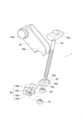
図1に示すように、車体はその左右において車両前後方向に延伸する一対のサイドメンバ3と、サイドメンバ3の車両後部側において車幅方向に延在する第1部材であるクロスメンバ10と、を備える。一対のサイドメンバ3の各々の車両前方部における車幅方向外側には、図に例示するようにダブルウィッシュボーン式のサスペンション5が設けられている。As shown in FIG. 1, the vehicle body is equipped with a pair ofside members 3 extending in the front-rear direction of the vehicle on the left and right sides, and across member 10, which is a first member extending in the vehicle width direction on the vehicle rear side of theside members 3. Adouble wishbone suspension 5 is provided on the vehicle width direction outer side at the front part of each of the pair ofside members 3, as illustrated in the figure.

サスペンション5はアッパーアーム5aと、ロアーアーム5bと、図示しないスプリングを内蔵するショックアブソーバ5cと、備える。また、アッパーアーム5aとロアーアーム5bとは、車両の前輪(図示せず)を支持するナックル(図示せず)によって車両上下方向において連結される。また、ショックアブソーバ5cは車両上下方向に延在し、その上端はサイドメンバ3に固定され、その下端はロアーアーム5bに所定の角度範囲で回転可能に連結される。Thesuspension 5 comprises anupper arm 5a, alower arm 5b, and a shock absorber 5c with a built-in spring (not shown). Theupper arm 5a and thelower arm 5b are connected in the vertical direction of the vehicle by a knuckle (not shown) that supports the front wheel (not shown). Theshock absorber 5c extends in the vertical direction of the vehicle, with its upper end fixed to theside member 3 and its lower end connected to thelower arm 5b so as to be rotatable within a predetermined angle range.

アッパーアーム5aは車両上下方向視でU字型の形状を有し、車幅方向内側の端部5dには、車両前後方向に向けて貫通する貫通孔が設けられている。この貫通孔にはトーションバー7が挿通されており、例えば鋸歯状の凹凸が嵌合することによってアッパーアーム5aとトーションバー7とが連結される。Theupper arm 5a has a U-shape when viewed from the top to bottom of the vehicle, and a through hole that penetrates in the front-to-rear direction of the vehicle is provided at theend 5d on the inner side in the vehicle width direction. Atorsion bar 7 is inserted into this through hole, and theupper arm 5a and thetorsion bar 7 are connected by, for example, fitting together sawtooth-shaped projections and recesses.

トーションバー7は、サイドメンバ3に沿うようにして車両前後方向に延在する円柱状の長尺部材であり、例えばバネ鋼鋼材(SUP材)等の金属から構成される。トーションバー7の車両前方側端部は前述のようにアッパーアーム5aと連結され、車両後方側端部は、車幅方向内側に向けて延在する第2部材であるアンカアーム20と連結されている。アンカアーム20は、車両用締結構造1を用いてクロスメンバ10に固定される。Thetorsion bar 7 is a cylindrical, long member that extends in the fore-and-aft direction of the vehicle along theside member 3, and is made of metal such as spring steel (SUP material). The front end of thetorsion bar 7 is connected to theupper arm 5a as described above, and the rear end is connected to theanchor arm 20, which is a second member that extends inward in the vehicle width direction. Theanchor arm 20 is fixed to thecross member 10 using thevehicle fastening structure 1.

アンカアーム20は、トーションバー7の軸周りに所定の角度捻じられた状態で、車両用締結構造1を用いて位置決めされている。これにより、トーションバー7はその軸周り方向の捻じりモーメントを受けた状態で、アッパーアーム5aとアンカアーム20との間に固定される。そして、トーションバー7に生じた反発力はアッパーアーム5aに対して入力される。このため、アンカアーム20を捻じる角度を調整することにより、トーションバー7に入力する捻じりモーメントを調整し、その結果、アッパーアーム5aのトーションバー7の軸周り方向のモーメントを調整することができる。Theanchor arm 20 is positioned using thevehicle fastening structure 1 in a state where it is twisted a predetermined angle around the axis of thetorsion bar 7. As a result, thetorsion bar 7 is fixed between theupper arm 5a and theanchor arm 20 in a state where it is subjected to a torsional moment around its axis. The repulsive force generated in thetorsion bar 7 is input to theupper arm 5a. Therefore, by adjusting the angle at which theanchor arm 20 is twisted, the torsional moment input to thetorsion bar 7 can be adjusted, and as a result, the moment around the axis of thetorsion bar 7 of theupper arm 5a can be adjusted.

例えば、トーションバー7に対して図1の矢印B方向に向けた捻じりモーメントを増加することにより、アッパーアーム5a及びロアーアーム5bは車幅方向外側が下がるように傾く。これにより、車両における前輪の相対的位置を車両下方に移動させ、車両前部における車高を高くする(リフトアップする)ことができる。また、トーションバー7に対して入力される捻じりモーメントを減少させることにより、車両前部における車高を低くする(ロアーダウンする)ことができる。For example, by increasing the twisting moment applied to thetorsion bar 7 in the direction of arrow B in FIG. 1, theupper arm 5a and thelower arm 5b are tilted so that the outer side in the vehicle width direction is lowered. This moves the relative position of the front wheels of the vehicle downward, making it possible to increase the vehicle height at the front of the vehicle (lift up). Also, by decreasing the twisting moment applied to thetorsion bar 7, it is possible to lower the vehicle height at the front of the vehicle (lower down).

車両はこのようなサスペンション5、トーションバー7、アンカアーム20及び車両用締結構造1を車幅方向左右それぞれにおいて有するため、車両前部における車高を左右それぞれに調整することができる。従って、車両は、左右の前輪の各々について、車両における相対的な上下方向位置を調整する、姿勢調整機構を備える。Since the vehicle has such asuspension 5,torsion bar 7,anchor arm 20, andvehicle fastening structure 1 on each side in the vehicle width direction, the vehicle height at the front of the vehicle can be adjusted on each side. Therefore, the vehicle is equipped with a posture adjustment mechanism that adjusts the relative vertical position of each of the left and right front wheels on the vehicle.

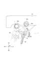
実施形態に係る車両用締結構造1は、図2乃至図6に示すように、ボルト50と、第1ナット60と、第2ナット70と、第3部材であるアンカ部材30と、第4部材であるアンカブラケット40と、を備える。As shown in Figures 2 to 6, thevehicle fastening structure 1 according to the embodiment includes abolt 50, afirst nut 60, asecond nut 70, ananchor member 30 as a third member, and ananchor bracket 40 as a fourth member.

ボルト50は、その軸方向(以下、ボルト軸方向)における、一側(図2における下方側)に所定の範囲でネジ山が形成され、他側(図2における上方側)の端部にはスイベル50aを有し、車体のクロスメンバ10に設けられている。Thebolt 50 has a thread formed on one side (the lower side in FIG. 2) in a predetermined range in its axial direction (hereinafter referred to as the bolt axial direction), has a swivel 50a at the end on the other side (the upper side in FIG. 2), and is attached to thecross member 10 of the vehicle body.

スイベル50aは、ボルト軸方向に対して垂直、かつトーションバー7の軸方向に平行な方向に延在する半円柱状の部材である。図1に示すように、スイベル50aはクロスメンバ10に設けられた車両前後方向に貫通する円形の穴部10aに挿し込まれる。このため、ボルト50はスイベル50aを支軸として所定の角度範囲で揺動可能な状態で、クロスメンバ10によって保持される。The swivel 50a is a semi-cylindrical member that extends perpendicular to the bolt axis direction and parallel to the axial direction of thetorsion bar 7. As shown in FIG. 1, the swivel 50a is inserted into acircular hole 10a that penetrates thecross member 10 in the fore-and-aft direction of the vehicle. Therefore, thebolt 50 is held by thecross member 10 in a state in which it can swing within a predetermined angle range with the swivel 50a as a pivot.

アンカ部材30は、ボルト軸方向に対して垂直、かつスイベル50aの長手方向に平行な方向に延在する半円柱状の部材であり、例えば鋼、ステンレス、アルミニウム等の金属からなる。アンカ部材30の側面のうち、ボルト軸方向一側の側面はボルト軸方向に対して垂直な平面であり、他側の側面はアンカ部材30の延在方向の周りに湾曲する曲面(上曲面)である。また、アンカ部材30の長手方向中央部には、平面及び上曲面を貫通する円形の穴部(アンカ穴部30a)が形成されている。アンカ穴部30aの内径はボルト50の軸の外径よりも大きい。また、アンカ部材30の長手方向両端部には、ボルト軸方向と平行で平坦な側面30bが形成され、側面30bにはアンカ部材30の長手方向に沿って突出する突出部30cが形成されている。換言すれば、アンカ部材30は、その長手方向に突出する突出部30cを備える。Theanchor member 30 is a semi-cylindrical member extending perpendicular to the bolt axis direction and parallel to the longitudinal direction of the swivel 50a, and is made of metal such as steel, stainless steel, or aluminum. Of the sides of theanchor member 30, one side in the bolt axis direction is a flat surface perpendicular to the bolt axis direction, and the other side is a curved surface (upper curved surface) that curves around the extending direction of theanchor member 30. In addition, a circular hole (anchor hole 30a) that penetrates the flat surface and the upper curved surface is formed in the longitudinal center of theanchor member 30. The inner diameter of theanchor hole 30a is larger than the outer diameter of the shaft of thebolt 50. In addition,flat side surfaces 30b parallel to the bolt axis direction are formed at both longitudinal ends of theanchor member 30, and protrudingportions 30c protruding along the longitudinal direction of theanchor member 30 are formed on theside surfaces 30b. In other words, theanchor member 30 has protrudingportions 30c protruding in its longitudinal direction.

図示した例では、突出部30cの側面のうち、ボルト軸方向他側の側面は、突出部30cの突出方向周りに湾曲する曲面となっている。もっとも、ボルト軸方向他側の側面以外の側面が湾曲する曲面となっていてもよい。換言すれば、突出部30cが突出する方向と平行な軸方向視において、突出部30cの輪郭の少なくとも一部は湾曲する。In the illustrated example, the side of theprotrusion 30c on the other side in the bolt axial direction is a curved surface that curves around the protruding direction of theprotrusion 30c. However, a side other than the side on the other side in the bolt axial direction may also be a curved surface. In other words, at least a portion of the contour of theprotrusion 30c is curved when viewed in the axial direction parallel to the protruding direction of theprotrusion 30c.

第1ナット60は、ボルト50と螺合する部材であり、アンカ部材30よりもボルト軸方向の一側に配置される。第2ナット70は、第1ナット60よりもボルト50の軸方向一側においてボルト50に螺合する部材である。第2ナット70は第1ナット60の緩みを防止するために配置される部材であり、第1ナット60と第2ナット70とでダブルナット構造を構成する。Thefirst nut 60 is a member that screws onto thebolt 50, and is positioned on one side of the bolt axial direction relative to theanchor member 30. Thesecond nut 70 is a member that screws onto thebolt 50 on one side of the bolt axial direction relative to thefirst nut 60. Thesecond nut 70 is a member that is positioned to prevent thefirst nut 60 from loosening, and thefirst nut 60 and thesecond nut 70 form a double nut structure.

アンカブラケット40は第1ナット60と第2ナット70との間に介挿される部材であり、例えば鋼、ステンレス、アルミニウム等の金属からなる。また、アンカブラケット40は、第1ナット60と第2ナット70とに挟持される座金部40aと、アンカ部材30に当接する当接部40bとを有する。Theanchor bracket 40 is a member that is inserted between thefirst nut 60 and thesecond nut 70, and is made of a metal such as steel, stainless steel, or aluminum. Theanchor bracket 40 also has awasher portion 40a that is sandwiched between thefirst nut 60 and thesecond nut 70, and anabutment portion 40b that abuts against theanchor member 30.

図示した例では、座金部40aはボルト軸方向に対して垂直な方向に延在する平板であり、その一部はボルト軸方向と平行な軸方向視(ボルト軸方向視)で略U字の形状に切り欠かれ、座金切欠き部40dが形成されている。座金切欠き部40dにボルト50を通すことにより第1ナット60と第2ナット70との間に座金部を配置し、第2ナット70を第1ナット60に向けて締め込むことにより、座金部40aを第1ナット60と第2ナット70との間に挟持することができる。In the illustrated example, thewasher portion 40a is a flat plate extending in a direction perpendicular to the bolt axis direction, and a portion of thewasher portion 40a is cut out in an approximately U-shape when viewed in an axial direction parallel to the bolt axis direction (when viewed in the bolt axis direction), forming thewasher notch portion 40d. The washer portion is placed between thefirst nut 60 and thesecond nut 70 by passing thebolt 50 through thewasher notch portion 40d, and thewasher portion 40a can be sandwiched between thefirst nut 60 and thesecond nut 70 by tightening thesecond nut 70 toward thefirst nut 60.

当接部40bは、座金部40aが第1ナット60と第2ナット70とによって挟持された状態において、ボルト軸方向と直交する方向における両端部の各々からボルト軸方向他側に向けて立設された一対の壁部である。なお、アンカ部材30の長手方向両端の平面である側面30b同士の間の寸法と、当接部40b同士の間の寸法とはほぼ等しく構成されていてもよい。なお、図示した例ではアンカブラケット40は一対の当接部40bを備えるが、これに限定されない。1つの当接部40bが座金部40aの周縁部に沿って立設されていてもよい。Theabutment portions 40b are a pair of walls erected from both ends in a direction perpendicular to the bolt axis direction toward the other side in the bolt axis direction when thewasher portion 40a is sandwiched between thefirst nut 60 and thesecond nut 70. The dimension between the side faces 30b, which are flat surfaces at both longitudinal ends of theanchor member 30, and the dimension between theabutment portions 40b may be configured to be approximately equal. In the illustrated example, theanchor bracket 40 has a pair ofabutment portions 40b, but is not limited to this. Oneabutment portion 40b may be erected along the periphery of thewasher portion 40a.

また、当接部40bには、その一部を切り欠くことにより溝部40cが形成されている。溝部40cは、当接部40bの立設する方向に対して垂直な方向に所定の幅で切り取られるとともに、当接部40bが立設される方向に向けて所定の幅で切り取られ形成される。このため、図に例示するように当接部40bは全体としてフック状の形状をなす。よって、溝部40cは後述するように突出部30cと掛合可能に構成されている。In addition, agroove 40c is formed in theabutment portion 40b by cutting out a portion of it. Thegroove 40c is cut out to a predetermined width in a direction perpendicular to the direction in which theabutment portion 40b stands, and is also cut out to a predetermined width in the direction in which theabutment portion 40b stands. Therefore, as shown in the figure, theabutment portion 40b has a hook-like shape as a whole. Therefore, thegroove 40c is configured to be able to engage with theprotrusion 30c, as described below.

次に、図2乃至図6を参照しながら、実施形態に係る車両用締結構造1に係る締結方法を説明する。Next, the fastening method for thevehicle fastening structure 1 according to the embodiment will be described with reference to Figures 2 to 6.

まず、アンカ部材30のアンカ穴部30aに、ボルト50が遊びを持った状態で挿通される。そして、アンカ部材30をボルト50に沿ってボルト軸方向他側に向けて移動することにより、ボルト50上の所定位置でアンカ部材30とアンカアーム20とを当接させる。First, thebolt 50 is inserted with some play into theanchor hole 30a of theanchor member 30. Then, theanchor member 30 is moved along thebolt 50 toward the other side in the bolt axial direction, so that theanchor member 30 and theanchor arm 20 come into contact with each other at a predetermined position on thebolt 50.

アンカアーム20の一端部にはトーションバー7を挿し込み固定するためのアーム穴部20aが設けられ、他端部のボルト軸方向一側には、アンカ部材30と摺動可能に嵌め合わされるように構成されたアーム切欠き部20bが形成されている。図示した例では、アーム切欠き部20bは、トーションバー7の延在方向と平行な軸方向視で、アンカアーム20の他端部を半円弧状に切り欠くことにより形成される。ここで、アーム切欠き部20bとアンカ部材30の上曲面とは、略同一の曲率を備える。このため、アンカアーム20とアンカ部材30とは、アンカ部材30の長手方向と平行な軸を中心として摺動可能に嵌め合わせることができる。その一方で、アンカアーム20は、アーム穴部20aに連結されたトーションバー7によってボルト50の軸周りの回転を拘束されているため、アンカ部材30のボルト50の軸周りの回転は、アンカアーム20によって拘束される。従って、アンカ部材30は、アンカアーム20によってボルト50の軸周りの回転を拘束された状態で、ボルト50に遊嵌される。Anarm hole portion 20a is provided at one end of theanchor arm 20 for inserting and fixing thetorsion bar 7, and anarm notch portion 20b configured to be slidably fitted with theanchor member 30 is formed on one side of the bolt axial direction of the other end. In the illustrated example, thearm notch portion 20b is formed by cutting out the other end of theanchor arm 20 in a semicircular arc shape when viewed in the axial direction parallel to the extension direction of thetorsion bar 7. Here, thearm notch portion 20b and the upper curved surface of theanchor member 30 have approximately the same curvature. Therefore, theanchor arm 20 and theanchor member 30 can be slidably fitted together around an axis parallel to the longitudinal direction of theanchor member 30. On the other hand, theanchor arm 20 is restrained from rotating around the axis of thebolt 50 by thetorsion bar 7 connected to thearm hole portion 20a, so that the rotation of theanchor member 30 around the axis of thebolt 50 is restrained by theanchor arm 20. Therefore, theanchor member 30 is loosely fitted onto thebolt 50 while being restricted from rotating around the axis of thebolt 50 by theanchor arm 20.

なお、ダブルナットを用いた他の車体用部材の締結構造に車両用締結構造1を用いた場合には、第3部材のボルト50の軸周りの回転を拘束する第2部材は、アンカアーム20以外の部材であってもよい。また、第3部材の形状は上述のアンカ部材30の形状に限定されず、第2部材の形状に応じて適宜変更することができる。When thevehicle fastening structure 1 is used in a fastening structure for other vehicle body components using a double nut, the second member that restricts the rotation of thebolt 50 of the third member about its axis may be a member other than theanchor arm 20. In addition, the shape of the third member is not limited to the shape of theanchor member 30 described above, and can be changed as appropriate depending on the shape of the second member.

次に、第1ナット60をボルト50のネジ山に対して締め込む。これにより、第1ナット60のボルト軸方向他側の座面は、アンカ部材30のボルト軸方向一側に当接し、アンカ部材30のボルト軸方向一側への移動は第1ナット60により規制される。従って、第1ナット60は、ボルト50に螺合して、ボルト50の軸方向一側へのアンカ部材30の移動を規制する。これにより、アンカ部材30のボルト50に沿った移動は、ボルト軸方向一側で当接するアンカアーム20と、ボルト軸方向他側で当接する第1ナット60とによって規制されることとなる。Next, thefirst nut 60 is tightened onto the threads of thebolt 50. As a result, the seating surface on the other side of the bolt axial direction of thefirst nut 60 abuts against one side of the bolt axial direction of theanchor member 30, and movement of theanchor member 30 to one side in the bolt axial direction is restricted by thefirst nut 60. Therefore, thefirst nut 60 screws onto thebolt 50 and restricts movement of theanchor member 30 to one side in the axial direction of thebolt 50. As a result, movement of theanchor member 30 along thebolt 50 is restricted by theanchor arm 20 abutting against one side in the bolt axial direction and thefirst nut 60 abutting against the other side in the bolt axial direction.

さらに、図6に示すように、アンカ部材30とアンカアーム20とが嵌合した状態で、さらに第1ナット60をボルト軸方向他側に向けて締め込むことによって、アンカ部材30がボルト50に沿ってボルト軸方向他側に向けて移動する。これにより、アンカアーム20はアンカ部材30に押され、トーションバー7の軸方向周りを矢印C方向に回転し、所定の角度で位置決めされる。これにより、トーションバー7には捻じりモーメントが入力され反発力が生じる。当該反発力はトーションバー7からサスペンション5のアッパーアーム5aに入力され、前述のように車両の姿勢を調整することができる。なお、第1ナット60を締め込む距離は、所望の車両姿勢に応じて適宜調整することができる。Furthermore, as shown in FIG. 6, when theanchor member 30 and theanchor arm 20 are engaged, thefirst nut 60 is further tightened toward the other side of the bolt axial direction, so that theanchor member 30 moves along thebolt 50 toward the other side of the bolt axial direction. As a result, theanchor arm 20 is pushed by theanchor member 30 and rotates around the axial direction of thetorsion bar 7 in the direction of arrow C, and is positioned at a predetermined angle. As a result, a torsional moment is input to thetorsion bar 7, generating a repulsive force. This repulsive force is input from thetorsion bar 7 to theupper arm 5a of thesuspension 5, and the vehicle posture can be adjusted as described above. The distance by which thefirst nut 60 is tightened can be appropriately adjusted according to the desired vehicle posture.

次に、図3に示すように、アンカブラケット40の座金部40aに形成された座金切欠き部40dにボルト50を通すとともに、溝部40cにアンカ部材30の突出部30cを通し、突出部30cのボルト軸方向他側の面に、溝部40cのボルト軸方向一側の縁部を引っ掛けるようにして、アンカブラケット40を一時的に保持した状態(仮保持状態)にする。この状態では、突出部30cのボルト軸方向一側の面と、溝部40cのボルト軸方向一側の縁部とは所定の距離を隔てて離間する。また、第1ナット60のボルト軸方向一側の座面と、座金部40aのボルト軸方向他側の面とは、所定の距離を隔てて離間する。Next, as shown in FIG. 3, thebolt 50 is passed through thewasher notch 40d formed in thewasher portion 40a of theanchor bracket 40, and theprotrusion 30c of theanchor member 30 is passed through thegroove 40c, and the edge of one side of thegroove 40c in the bolt axial direction is hooked onto the surface of the other side of theprotrusion 30c in the bolt axial direction, so that theanchor bracket 40 is temporarily held (temporarily held). In this state, the surface of one side of the bolt axial direction of theprotrusion 30c and the edge of one side of thegroove 40c in the bolt axial direction are separated by a predetermined distance. Also, the seat surface of one side of the bolt axial direction of thefirst nut 60 and the surface of the other side of the bolt axial direction of thewasher portion 40a are separated by a predetermined distance.

なお、アンカブラケット40のうち、座金部40aの第1ナット60と第2ナット70との間で挟持される部分以外の部分は、第1ナット60から離間する。このため、当接部40bと第1ナット60の側面とは、所定の距離を隔てて離間する。従って、当接部40bと第1ナット60の側面とが干渉することがなく、アンカ部材30に対する第1ナット60の相対角度を自由に設定することができる。Theanchor bracket 40 has a portion of thewasher portion 40a other than the portion that is sandwiched between thefirst nut 60 and thesecond nut 70 spaced apart from thefirst nut 60. Therefore, theabutment portion 40b and the side surface of thefirst nut 60 are spaced apart at a predetermined distance. Therefore, theabutment portion 40b and the side surface of thefirst nut 60 do not interfere with each other, and the relative angle of thefirst nut 60 to theanchor member 30 can be freely set.

次に、ボルト50に第2ナット70をボルト軸方向他側に向けて締め込むことで、第2ナット70のボルト軸方向他側の座面と座金部40aのボルト軸方向一側の面とを当接させ、さらに第2ナット70を締め込み、アンカブラケット40をボルト軸方向他側に持ち上げる。このとき、当接部40bと、アンカアーム20によってボルト軸方向周りの回転を拘束されたアンカ部材30の側面30bと、が当接しているため、アンカブラケット40のボルト軸方向周りの回転はアンカ部材30によって規制されている。換言すれば、アンカ部材30は、当接部40bに当接しアンカブラケット40のボルト50の軸周りの回転を規制している。さらに、アンカ部材30の突出部30cが突出する方向における両端の平面である側面30bと、突出部30cが突出する方向において当該平面に対向する当接部40bの平面とは、アンカブラケット40がボルト50の軸周りに回転するときに干渉するように構成されていてもよい。このため、第2ナット70とともにアンカブラケット40とが供回りすることを抑制しながら、第2ナット70を締め込み、図4乃至図6に示すような、座金部40aを第1ナット60と第2ナット70とで挟持した状態(締結状態)とすることができる。なお、この状態では、突出部30cのボルト軸方向他側の面と、溝部40cのボルト軸方向他側の縁部とは、所定の距離を隔てて離間した状態となる。Next, thesecond nut 70 is tightened onto thebolt 50 toward the other side in the bolt axial direction, so that the seat surface on the other side of the bolt axial direction of thesecond nut 70 comes into contact with the surface on one side of the bolt axial direction of thewasher portion 40a, and thesecond nut 70 is tightened further to lift theanchor bracket 40 to the other side in the bolt axial direction. At this time, theabutment portion 40b comes into contact with theside surface 30b of theanchor member 30, whose rotation around the bolt axial direction is restricted by theanchor arm 20, so that the rotation of theanchor bracket 40 around the bolt axial direction is restricted by theanchor member 30. In other words, theanchor member 30 abuts against theabutment portion 40b to restrict the rotation of theanchor bracket 40 around the axis of thebolt 50. Furthermore, theside surface 30b, which is a flat surface at both ends in the direction in which the protrudingportion 30c of theanchor member 30 protrudes, and the flat surface of the abuttingportion 40b, which faces the flat surface in the direction in which the protrudingportion 30c protrudes, may be configured to interfere with each other when theanchor bracket 40 rotates around the axis of thebolt 50. Therefore, thesecond nut 70 can be tightened while preventing theanchor bracket 40 from rotating together with thesecond nut 70, and thewasher portion 40a can be clamped between thefirst nut 60 and the second nut 70 (fastened state) as shown in Figures 4 to 6. In this state, the surface on the other side of the bolt axis direction of the protrudingportion 30c and the edge on the other side of the bolt axis direction of thegroove portion 40c are spaced apart by a predetermined distance.

次に、実施形態に係る車両用締結構造1の作用効果を説明する。Next, the effects of thevehicle fastening structure 1 according to the embodiment will be described.

(1)実施形態に係る車両用締結構造1は、車体のクロスメンバ10に設けられたボルト50と、車体のアンカアーム20にボルト50の軸周りの回転を拘束された状態で、ボルト50に遊嵌されたアンカ部材30と、ボルト50に螺合して、ボルト50の軸方向一側へのアンカ部材30の移動を規制する第1ナット60と、第1ナット60よりもボルト50の軸方向一側においてボルト50に螺合した第2ナット70と、第1ナット60と第2ナット70との間に介挿されたアンカブラケット40と、を備える。アンカブラケット40は、第1ナット60と第2ナット70とに挟持される座金部40aと、アンカ部材30に当接する当接部40bとを有する。アンカ部材30は、当接部40bに当接しアンカブラケット40のボルト50の軸周りの回転を規制する。(1) Thevehicle fastening structure 1 according to the embodiment includes abolt 50 provided on across member 10 of a vehicle body, ananchor member 30 loosely fitted to thebolt 50 while the rotation of thebolt 50 around its axis is restrained by ananchor arm 20 of the vehicle body, afirst nut 60 screwed onto thebolt 50 to restrict movement of theanchor member 30 to one axial side of thebolt 50, asecond nut 70 screwed onto thebolt 50 on one axial side of thebolt 50 relative to thefirst nut 60, and ananchor bracket 40 interposed between thefirst nut 60 and thesecond nut 70. Theanchor bracket 40 has awasher portion 40a sandwiched between thefirst nut 60 and thesecond nut 70, and anabutment portion 40b that abuts against theanchor member 30. Theanchor member 30 abuts against theabutment portion 40b to restrict rotation of thebolt 50 around its axis of theanchor bracket 40.

このため、車両用締結構造1を図3に示す仮保持状態から、図4に示す締結状態にする際に、第2ナット70を締め込むと、第2ナット70から座金部40aを介して、アンカブラケット40と第1ナット60とにモーメントが伝達され、第1ナット60とアンカブラケット40とが第2ナット70と供回りしようとするが、アンカブラケット40の回転は、当接部40bがアンカ部材30に当接することで規制される。そのため、更に第2ナット70を締め込んでも、当該モーメントが第1ナット60に伝達されることはない。即ち、第1ナット60の供回りを防止するための工具を用いることなく、第2ナット70の締め付け作業を行うことができる。Therefore, when thevehicle fastening structure 1 is changed from the temporary holding state shown in FIG. 3 to the fastening state shown in FIG. 4, when thesecond nut 70 is tightened, a moment is transmitted from thesecond nut 70 to theanchor bracket 40 and thefirst nut 60 via thewasher portion 40a, and thefirst nut 60 and theanchor bracket 40 tend to rotate together with thesecond nut 70, but the rotation of theanchor bracket 40 is restricted by theabutment portion 40b abutting against theanchor member 30. Therefore, even if thesecond nut 70 is tightened further, the moment is not transmitted to thefirst nut 60. In other words, thesecond nut 70 can be tightened without using a tool to prevent thefirst nut 60 from rotating together.

また、第2ナット70を締め込むと、第1ナット60と第2ナット70とが座金部40aを介して互いに押し付けられ、座金部40aは圧縮される。この状態では、第1ナット60の内径部に設けられたネジ山のうち、座金部40aとは反対側を向いた面が、ボルト50のネジ山のうち座金部40a側を向いた面に対して押し当てられ、摩擦力が生じる。また、第2ナット70の内径部に設けられたネジ山のうち、座金部40aとは反対側を向いた面が、ボルト50のネジ山のうち座金部40a側を向いた面に対して押し当てられ、摩擦力が生じる。そして、ボルト50には、第1ナット60と第2ナット70との間において引っ張り方向の軸力が生じる。即ち、ダブルナットによる緩み止めの効果を得ることができる。When thesecond nut 70 is tightened, thefirst nut 60 and thesecond nut 70 are pressed against each other via thewasher portion 40a, and thewasher portion 40a is compressed. In this state, the surface of the thread on the inner diameter portion of thefirst nut 60 facing away from thewasher portion 40a is pressed against the surface of the thread of thebolt 50 facing thewasher portion 40a, generating a frictional force. The surface of the thread on the inner diameter portion of thesecond nut 70 facing away from thewasher portion 40a is pressed against the surface of the thread of thebolt 50 facing thewasher portion 40a, generating a frictional force. An axial force in the tensile direction is generated in thebolt 50 between thefirst nut 60 and thesecond nut 70. That is, the effect of preventing loosening by the double nut can be obtained.

(2)実施形態に係る車両用締結構造1は、アンカブラケット40のうち、座金部40aの第1ナット60と第2ナット70との間で挟持される部分以外の部分は、第1ナット60から離間する。(2) In thevehicle fastening structure 1 according to the embodiment, theanchor bracket 40 is spaced apart from thefirst nut 60 except for the portion of thewasher portion 40a that is clamped between thefirst nut 60 and thesecond nut 70.

これにより、第1ナット60の側面とアンカブラケット40の当接部とが接触することが無い。そのため、第1ナット60の側面にアンカブラケット40の一部を当接させることで第1ナット60の回転を拘束した場合と比較して、アンカ部材30に対する第1ナット60の相対角度を自由に設定できる。従って、第1ナット60のボルト50上の位置を自由に設定できる。This prevents contact between the side of thefirst nut 60 and the abutting portion of theanchor bracket 40. Therefore, compared to a case in which the rotation of thefirst nut 60 is restricted by abutting a part of theanchor bracket 40 against the side of thefirst nut 60, the relative angle of thefirst nut 60 with respect to theanchor member 30 can be freely set. Therefore, the position of thefirst nut 60 on thebolt 50 can be freely set.

(3)実施形態に係る車両用締結構造1では、アンカ部材30は、ボルト50の軸方向とは垂直な方向に向けて突出する突出部30cを備え、当接部40bには、突出部30cと掛合可能に構成された溝部40cが形成される。(3) In thevehicle fastening structure 1 according to the embodiment, theanchor member 30 has a protrudingportion 30c that protrudes in a direction perpendicular to the axial direction of thebolt 50, and the abuttingportion 40b has agroove portion 40c that is configured to be able to engage with the protrudingportion 30c.

これにより、第1ナット60でボルト50上におけるアンカ部材30の位置を調整した後、溝部40cにアンカ部材30の突出部30cを通すようにしてアンカブラケット40を配置することにより、突出部30cにアンカブラケット40を引っ掛けて一時的に保持することができる。そのため、アンカブラケット40の座金部40aを第1ナット60と第2ナット70との間で挟持する際に、アンカブラケット40を別途保持することなく、第2ナット70を締め込むことができる。従って、容易に第1ナット60と第2ナット70との間にアンカブラケット40を挟持することができる。As a result, after adjusting the position of theanchor member 30 on thebolt 50 with thefirst nut 60, theanchor bracket 40 can be placed so that the protrudingportion 30c of theanchor member 30 passes through thegroove portion 40c, and theanchor bracket 40 can be hooked onto the protrudingportion 30c and temporarily held in place. Therefore, when thewasher portion 40a of theanchor bracket 40 is clamped between thefirst nut 60 and thesecond nut 70, thesecond nut 70 can be tightened without separately holding theanchor bracket 40. Therefore, theanchor bracket 40 can be easily clamped between thefirst nut 60 and thesecond nut 70.

(4)実施形態に係る車両用締結構造1では、突出部30cが突出する方向と平行な軸方向視において、突出部30cの輪郭の少なくとも一部は湾曲する。(4) In thevehicle fastening structure 1 according to the embodiment, at least a portion of the contour of the protrudingportion 30c is curved when viewed in an axial direction parallel to the direction in which the protrudingportion 30c protrudes.

これにより、突出部30cは、突出部30cが突出する方向周りに湾曲する曲面を備える。そのため、アンカ部材30の突出部30cをアンカブラケット40の溝部40cに通す際の、突出部30cと当接部40bとの引っ掛かりが抑制される。従って、より容易にアンカブラケット40を突出部30cに引っ掛けて一時的に保持することができる。As a result, theprotrusion 30c has a curved surface that curves around the direction in which theprotrusion 30c protrudes. Therefore, when theprotrusion 30c of theanchor member 30 is passed through thegroove 40c of theanchor bracket 40, theprotrusion 30c is prevented from getting caught on theabutment portion 40b. Therefore, theanchor bracket 40 can be more easily hooked onto theprotrusion 30c and temporarily held in place.

(5)実施形態に係る車両用締結構造1は、アンカ部材30の突出部30cが突出する方向における両端の平面と、突出部30cが突出する方向において当該平面に対向する当接部40bの平面とは、アンカブラケット40がボルト50の軸周りに回転するときに干渉するように構成される。(5) Thevehicle fastening structure 1 according to the embodiment is configured so that the flat surfaces at both ends of theanchor member 30 in the direction in which the protrudingportion 30c protrudes and the flat surface of the abuttingportion 40b that faces the flat surface in the direction in which the protrudingportion 30c protrudes interfere with each other when theanchor bracket 40 rotates around the axis of thebolt 50.

これにより、アンカブラケット40を突出部30cに引っ掛けて一時的に保持した際に、ボルト50の軸周りにおいてアンカブラケット40が回転しようとしたとき、アンカ部材30と当接部40bとが干渉し、アンカブラケット40の回転が規制される。従って、より確実にアンカブラケット40を突出部30cに引っ掛けて一時的に保持することができる。As a result, when theanchor bracket 40 is hooked onto the protrudingportion 30c and temporarily held in place, if theanchor bracket 40 attempts to rotate around the axis of thebolt 50, theanchor member 30 interferes with theabutment portion 40b, restricting the rotation of theanchor bracket 40. Therefore, theanchor bracket 40 can be more reliably hooked onto the protrudingportion 30c and temporarily held in place.

なお、上記実施形態では、車体の姿勢調整機構においてアンカアーム20を所望の角度で位置決めするための締結構造を例にとって説明したが、車両用締結構造1をダブルナットを用いた他の車体用部材の締結構造にも用いることができることは勿論である。In the above embodiment, a fastening structure for positioning theanchor arm 20 at a desired angle in a vehicle body attitude adjustment mechanism has been described as an example, but it goes without saying that thevehicle fastening structure 1 can also be used as a fastening structure for other vehicle body components using double nuts.

1 車両用締結構造
10 クロスメンバ(第1部材)
20 アンカアーム(第2部材)
30 アンカ部材(第3部材)
30c 突出部
40 アンカブラケット(第4部材)
40a 座金部
40b 当接部
40c 溝部
50 ボルト
60 第1ナット
70 第2ナット
1Vehicle fastening structure 10 Cross member (first member)
20 anchor arm (second member)
30 anchor member (third member)
30c Protrusion 40 Anchor bracket (fourth member)
40a:washer portion 40b:abutment portion 40c: groove portion 50: bolt 60: first nut 70: second nut

Claims (5)

Translated fromJapanese
車体の第1部材に設けられたボルトと、
前記車体の第2部材に前記ボルトの軸周りの回転を拘束された状態で、前記ボルトに遊嵌された第3部材と、
前記ボルトに螺合して、前記ボルトの軸方向一側への前記第3部材の移動を規制する第1ナットと、
前記第1ナットよりも前記ボルトの軸方向一側において前記ボルトに螺合した第2ナットと、
前記第1ナットと前記第2ナットとの間に介挿された第4部材と、
を備え、
前記第4部材は、前記第1ナットと前記第2ナットとに挟持される座金部と、前記第3部材に当接する当接部とを有し、
前記第3部材は、前記当接部に当接し前記第4部材の前記ボルトの軸周りの回転を規制する、
車両用締結構造。
A bolt provided on a first member of a vehicle body;
a third member loosely fitted to the bolt in a state in which rotation of the bolt about its axis is constrained by the second member of the vehicle body;
A first nut that is screwed onto the bolt and restricts movement of the third member toward one axial side of the bolt;
A second nut screwed onto the bolt on one axial side of the bolt relative to the first nut;
a fourth member interposed between the first nut and the second nut;
Equipped with
The fourth member has a washer portion sandwiched between the first nut and the second nut and an abutment portion abutting against the third member,
The third member abuts against the abutment portion to restrict rotation of the fourth member around the axis of the bolt.
Fastening structure for vehicles.
前記第4部材の内、前記座金部の前記第1ナットと前記第2ナットとの間で挟持される部分以外の部分は、前記第1ナットから離間する、請求項1に記載の車両用締結構造。The vehicle fastening structure according to claim 1, wherein the portion of the fourth member other than the portion of the washer portion that is sandwiched between the first nut and the second nut is spaced apart from the first nut. 前記第3部材は、前記ボルトの軸方向とは垂直な方向に向けて突出する突出部を備え、
前記当接部には、前記突出部と掛合可能に構成された溝部が形成される、請求項1又は2に記載の車両用締結構造。
The third member includes a protruding portion protruding in a direction perpendicular to the axial direction of the bolt,
The fastening structure for a vehicle according to claim 1 or 2, wherein the contact portion is formed with a groove configured to be able to engage with the protrusion.
前記突出部が突出する方向と平行な軸方向視において、前記突出部の輪郭の少なくとも一部は湾曲する、請求項3に記載の車両用締結構造。The fastening structure for a vehicle according to claim 3, wherein at least a portion of the contour of the protrusion is curved when viewed in an axial direction parallel to the direction in which the protrusion protrudes. 前記第3部材の前記突出部が突出する方向における両端の平面と、前記突出部が突出する方向において当該平面に対向する前記当接部の平面とは、前記第4部材が前記ボルトの軸周りに回転するときに干渉するように構成される、請求項3又は4に記載の車両用締結構造。The vehicle fastening structure according to claim 3 or 4, wherein the flat surfaces of both ends of the third member in the direction in which the protruding portion protrudes and the flat surface of the abutting portion that faces the flat surfaces in the direction in which the protruding portion protrudes are configured to interfere with each other when the fourth member rotates around the axis of the bolt.
JP2021062821A2021-04-012021-04-01 Vehicle fastening structureActiveJP7571650B2 (en)

Priority Applications (1)

Application NumberPriority DateFiling DateTitle
JP2021062821AJP7571650B2 (en)2021-04-012021-04-01 Vehicle fastening structure

Applications Claiming Priority (1)

Application NumberPriority DateFiling DateTitle
JP2021062821AJP7571650B2 (en)2021-04-012021-04-01 Vehicle fastening structure

Publications (2)

Publication NumberPublication Date
JP2022158126A JP2022158126A (en)2022-10-17
JP7571650B2true JP7571650B2 (en)2024-10-23

Family

ID=83638463

Family Applications (1)

Application NumberTitlePriority DateFiling Date
JP2021062821AActiveJP7571650B2 (en)2021-04-012021-04-01 Vehicle fastening structure

Country Status (1)

CountryLink
JP (1)JP7571650B2 (en)

Citations (3)

* Cited by examiner, † Cited by third party
Publication numberPriority datePublication dateAssigneeTitle
JP2014070676A (en)2012-09-282014-04-21Daikin Ind LtdNut positioning jig for ceiling-embedded air conditioner and fitting method of ceiling-embedded air conditioner using the nut positioning jig
CN105299018A (en)2014-07-072016-02-03王鸿基Anti-looseness and anti-corrosion device for threaded connection
JP2020100961A (en)2018-12-202020-07-02泉 加藤Bolt support unit

Patent Citations (3)

* Cited by examiner, † Cited by third party
Publication numberPriority datePublication dateAssigneeTitle
JP2014070676A (en)2012-09-282014-04-21Daikin Ind LtdNut positioning jig for ceiling-embedded air conditioner and fitting method of ceiling-embedded air conditioner using the nut positioning jig
CN105299018A (en)2014-07-072016-02-03王鸿基Anti-looseness and anti-corrosion device for threaded connection
JP2020100961A (en)2018-12-202020-07-02泉 加藤Bolt support unit

Also Published As

Publication numberPublication date
JP2022158126A (en)2022-10-17

Similar Documents

PublicationPublication DateTitle
AU2005237913B2 (en)Vehicle height adjustment device and vehicle height adjustment method
KR100572264B1 (en) Wheel angle adjuster of vehicle suspension system
JP5304207B2 (en) Brake air guide structure
US4863148A (en)Apparatus for adjustment of automobile torsion bar suspension assembly
JPH09272446A (en) Tilt steering system
JP7571650B2 (en) Vehicle fastening structure
EP3395661B1 (en)Rear cushion device
JP7419924B2 (en) Vehicle suspension equipment
MX2007002860A (en)One end adjustable torque rod.
JP2010266009A (en) Shock absorber
CN101306696B (en)Tilt steering apparatus
JP6666818B2 (en) A rotating shaft fastening structure and a method of assembling the rotating shaft fastening structure.
KR101845216B1 (en)Camber controlling device for vehicle
US5540417A (en)Adjustable coil spring assembly
CN114435494A (en) Method for adjusting the alignment of a truck or tractor vehicle with an adjustable Panhard link and its cab relative to its frame
CN117222535A (en)Clamp set with alignment features and circular axle
JP6972760B2 (en) Steering device
KR100261421B1 (en)Lower arm mounting structure of suspension
JP6562293B2 (en) Stabilizer holding structure
US3243199A (en)Torsion spring vehicle suspension
KR101143649B1 (en)Tilting assembly of steering column
JP5589752B2 (en) Vehicle steering device
KR20250114214A (en)Suspension tuning apparatus for rear axle for vehicle
JP2011074641A (en)Mirror for working machine
JPS59199381A (en)Assembling method of suspension of automobile

Legal Events

DateCodeTitleDescription
A621Written request for application examination

Free format text:JAPANESE INTERMEDIATE CODE: A621

Effective date:20240208

A977Report on retrieval

Free format text:JAPANESE INTERMEDIATE CODE: A971007

Effective date:20240830

TRDDDecision of grant or rejection written
A01Written decision to grant a patent or to grant a registration (utility model)

Free format text:JAPANESE INTERMEDIATE CODE: A01

Effective date:20240910

A61First payment of annual fees (during grant procedure)

Free format text:JAPANESE INTERMEDIATE CODE: A61

Effective date:20240923

R150Certificate of patent or registration of utility model

Ref document number:7571650

Country of ref document:JP

Free format text:JAPANESE INTERMEDIATE CODE: R150


[8]ページ先頭

©2009-2025 Movatter.jp