JP7570895B2 - Weight management device and biological information monitoring system - Google Patents
Weight management device and biological information monitoring systemDownload PDFInfo
- Publication number
- JP7570895B2 JP7570895B2JP2020190685AJP2020190685AJP7570895B2JP 7570895 B2JP7570895 B2JP 7570895B2JP 2020190685 AJP2020190685 AJP 2020190685AJP 2020190685 AJP2020190685 AJP 2020190685AJP 7570895 B2JP7570895 B2JP 7570895B2
- Authority
- JP
- Japan
- Prior art keywords
- weight
- management device
- subject
- unit
- display
- Prior art date
- Legal status (The legal status is an assumption and is not a legal conclusion. Google has not performed a legal analysis and makes no representation as to the accuracy of the status listed.)
- Active
Links
Images


Classifications
- G—PHYSICS
- G01—MEASURING; TESTING
- G01G—WEIGHING
- G01G19/00—Weighing apparatus or methods adapted for special purposes not provided for in the preceding groups
- G01G19/44—Weighing apparatus or methods adapted for special purposes not provided for in the preceding groups for weighing persons
- G—PHYSICS
- G01—MEASURING; TESTING
- G01G—WEIGHING
- G01G19/00—Weighing apparatus or methods adapted for special purposes not provided for in the preceding groups
- G01G19/44—Weighing apparatus or methods adapted for special purposes not provided for in the preceding groups for weighing persons
- G01G19/445—Weighing apparatus or methods adapted for special purposes not provided for in the preceding groups for weighing persons in a horizontal position
- A—HUMAN NECESSITIES
- A61—MEDICAL OR VETERINARY SCIENCE; HYGIENE
- A61B—DIAGNOSIS; SURGERY; IDENTIFICATION
- A61B5/00—Measuring for diagnostic purposes; Identification of persons
- A61B5/103—Measuring devices for testing the shape, pattern, colour, size or movement of the body or parts thereof, for diagnostic purposes
- A61B5/1036—Measuring load distribution, e.g. podologic studies
- A—HUMAN NECESSITIES
- A61—MEDICAL OR VETERINARY SCIENCE; HYGIENE
- A61B—DIAGNOSIS; SURGERY; IDENTIFICATION
- A61B5/00—Measuring for diagnostic purposes; Identification of persons
- A61B5/103—Measuring devices for testing the shape, pattern, colour, size or movement of the body or parts thereof, for diagnostic purposes
- A61B5/11—Measuring movement of the entire body or parts thereof, e.g. head or hand tremor or mobility of a limb
- A61B5/1113—Local tracking of patients, e.g. in a hospital or private home
- A61B5/1115—Monitoring leaving of a patient support, e.g. a bed or a wheelchair
- A—HUMAN NECESSITIES
- A61—MEDICAL OR VETERINARY SCIENCE; HYGIENE
- A61B—DIAGNOSIS; SURGERY; IDENTIFICATION
- A61B5/00—Measuring for diagnostic purposes; Identification of persons
- A61B5/68—Arrangements of detecting, measuring or recording means, e.g. sensors, in relation to patient
- A61B5/6887—Arrangements of detecting, measuring or recording means, e.g. sensors, in relation to patient mounted on external non-worn devices, e.g. non-medical devices
- A61B5/6891—Furniture
- A—HUMAN NECESSITIES
- A61—MEDICAL OR VETERINARY SCIENCE; HYGIENE
- A61B—DIAGNOSIS; SURGERY; IDENTIFICATION
- A61B5/00—Measuring for diagnostic purposes; Identification of persons
- A61B5/68—Arrangements of detecting, measuring or recording means, e.g. sensors, in relation to patient
- A61B5/6887—Arrangements of detecting, measuring or recording means, e.g. sensors, in relation to patient mounted on external non-worn devices, e.g. non-medical devices
- A61B5/6892—Mats
- A—HUMAN NECESSITIES
- A61—MEDICAL OR VETERINARY SCIENCE; HYGIENE
- A61B—DIAGNOSIS; SURGERY; IDENTIFICATION
- A61B5/00—Measuring for diagnostic purposes; Identification of persons
- A61B5/74—Details of notification to user or communication with user or patient; User input means
- A61B5/742—Details of notification to user or communication with user or patient; User input means using visual displays
- A61B5/7445—Display arrangements, e.g. multiple display units
- A—HUMAN NECESSITIES
- A61—MEDICAL OR VETERINARY SCIENCE; HYGIENE
- A61B—DIAGNOSIS; SURGERY; IDENTIFICATION
- A61B5/00—Measuring for diagnostic purposes; Identification of persons
- A61B5/74—Details of notification to user or communication with user or patient; User input means
- A61B5/7475—User input or interface means, e.g. keyboard, pointing device, joystick
- G—PHYSICS
- G01—MEASURING; TESTING
- G01G—WEIGHING
- G01G19/00—Weighing apparatus or methods adapted for special purposes not provided for in the preceding groups
- G01G19/52—Weighing apparatus combined with other objects, e.g. furniture
- A—HUMAN NECESSITIES
- A61—MEDICAL OR VETERINARY SCIENCE; HYGIENE
- A61B—DIAGNOSIS; SURGERY; IDENTIFICATION
- A61B2562/00—Details of sensors; Constructional details of sensor housings or probes; Accessories for sensors
- A61B2562/02—Details of sensors specially adapted for in-vivo measurements
- A61B2562/0252—Load cells
Landscapes
- Health & Medical Sciences (AREA)
- Life Sciences & Earth Sciences (AREA)
- Physics & Mathematics (AREA)
- Heart & Thoracic Surgery (AREA)
- Molecular Biology (AREA)
- Veterinary Medicine (AREA)
- Biophysics (AREA)
- Pathology (AREA)
- Engineering & Computer Science (AREA)
- Biomedical Technology (AREA)
- Public Health (AREA)
- Medical Informatics (AREA)
- General Health & Medical Sciences (AREA)
- Surgery (AREA)
- Animal Behavior & Ethology (AREA)
- General Physics & Mathematics (AREA)
- Oral & Maxillofacial Surgery (AREA)
- Dentistry (AREA)
- Physiology (AREA)
- Measuring And Recording Apparatus For Diagnosis (AREA)
- Measurement Of The Respiration, Hearing Ability, Form, And Blood Characteristics Of Living Organisms (AREA)
Description
Translated fromJapanese本発明は、体重管理装置、及び生体情報モニタリングシステムに関する。The present invention relates to a weight management device and a biological information monitoring system.
医療や介護の分野において、荷重検出器を介してベッド上の被験者の荷重を検出し、検出した荷重に基づいて被験者の体重、呼吸数、心拍数等の生体情報を取得することが提案されている。In the fields of medicine and nursing care, it has been proposed to detect the load of a subject on a bed via a load detector and obtain biometric information such as the subject's weight, respiratory rate, and heart rate based on the detected load.
特許文献1は、ベッドの脚にかかる荷重を測定するベッドスケール体重計と、当該ベッドスケール体重計の検出結果に基づいてベッド上に滞在する被測定者の体重等の生体条件を表示する表示手段を具備するベッドを開示している。Patent document 1 discloses a bed equipped with a bed scale that measures the load on the legs of the bed and a display means that displays the biological conditions, such as the weight, of a person staying on the bed based on the detection results of the bed scale.
本発明は、ベッドサイドで容易に被験者の体重を管理することができ、且つ操作性の高い体重管理装置、及び当該体重管理装置を備える生体情報モニタリングシステムを提供することを目的とする。The present invention aims to provide a weight management device that can easily manage a subject's weight at the bedside and is easy to operate, and a biological information monitoring system that includes the weight management device.
本発明の第1の態様に従えば、
ベッド上の被験者の生体情報を該被験者の荷重を検出する荷重検出器の検出値に基づいてモニタする生体情報モニタリングシステムにおいて用いられる体重管理装置であって、
筐体と、
前記筐体の外面に設けられ、且つ前記検出値に基づく前記被験者の体重を表示するディスプレイと、
前記筐体の外面に設けられ、且つ前記ベッドに着脱可能である取付部とを備える体重管理装置が提供される。 According to a first aspect of the present invention,
1. A body weight management device for use in a biological information monitoring system that monitors biological information of a subject on a bed based on a detection value of a load detector that detects the load of the subject,
A housing and
a display provided on an outer surface of the housing and displaying the weight of the subject based on the detected value;
A weight management device is provided that includes an attachment portion that is provided on an outer surface of the housing and is detachable from the bed.
第1の態様の体重管理装置において、前記取付部は、該取付部を前記ベッドに取り付けた状態において前記ディスプレイの法線方向が可変となるように構成されていてもよい。In the first aspect of the weight management device, the attachment unit may be configured so that the normal direction of the display is variable when the attachment unit is attached to the bed.
第1の態様の体重管理装置において、前記体重管理装置又は前記生体情報モニタリングシステムが、前記検出値に基づいて前記被験者の体重を周期的に算出する体重算出部を備えてもよい。In the weight management device of the first aspect, the weight management device or the biological information monitoring system may include a weight calculation unit that periodically calculates the subject's weight based on the detection value.
第1の態様の体重管理装置において、前記生体情報モニタリングシステム又は前記体重管理装置が、所定期間における前記被験者の体重の変化量と所定の閾値との比較に基づいて、前記被験者の生体情報に関する報知を行う報知制御部を備えてもよい。In the weight management device of the first aspect, the biological information monitoring system or the weight management device may include a notification control unit that issues a notification regarding the biological information of the subject based on a comparison between the amount of change in the subject's weight over a predetermined period of time and a predetermined threshold value.
第1の態様の体重管理装置は、前記報知を停止するための停止ボタンを更に備えてもよく、前記停止ボタンが前記筐体の幅方向の中央部に設けられていてもよい。The weight management device of the first aspect may further include a stop button for stopping the notification, and the stop button may be provided in the center of the width of the housing.
第1の態様の体重管理装置は、記録ボタンと、履歴ボタンと、前記ディスプレイの表示内容を制御する表示制御部とを更に備えてもよく、前記表示制御部は、記録ボタンが操作された時刻と当該時刻に対応する前記被験者の体重とを関連付けて記憶部に記憶させてもよく、前記履歴ボタンが操作された時に、前記記憶部に記憶させた前記被験者の体重を関連付けられた時刻と共に前記ディスプレイに表示してもよい。The weight management device of the first aspect may further include a record button, a history button, and a display control unit that controls the display content of the display, and the display control unit may store in a memory unit the time when the record button is operated and the subject's weight corresponding to that time in association with each other, and may display on the display the subject's weight stored in the memory unit together with the associated time when the history button is operated.
第1の態様の体重管理装置は、記録ボタンと、前記ディスプレイの表示内容を制御する表示制御部とを更に備えてもよく、前記表示制御部は、第1時刻に前記記録ボタンが操作された時に、第1時刻に対応する前記被験者の第1体重を記憶部に記憶させてもよく、第1時刻よりも後の第2時刻に前記記録ボタンが操作された時に、第2時刻に対応する前記被験者の第2体重を前記記憶部に記憶させてもよく、前記第1体重と前記第2体重との差分を前記ディスプレイに表示してもよい。The weight management device of the first aspect may further include a record button and a display control unit that controls the display content of the display, and the display control unit may store in a memory unit a first weight of the subject corresponding to a first time when the record button is operated at a first time, and may store in the memory unit a second weight of the subject corresponding to a second time when the record button is operated at a second time after the first time, and may display a difference between the first weight and the second weight on the display.
本発明の第2の態様に従えば、
ベッド上の被験者の荷重を検出する荷重検出器と、
前記荷重検出器の検出値に基づいて前記被験者の生体情報を取得する生体情報取得部と、
第1の態様の体重管理装置とを備える生体情報モニタリングシステムが提供される。 According to a second aspect of the present invention,
a load detector for detecting the load of a subject on the bed;
a biometric information acquiring unit that acquires biometric information of the subject based on a detection value of the load detector;
A biological information monitoring system is provided, comprising the weight management device of the first aspect.
本発明の体重管理装置はベッドサイドで容易に被験者の体重を管理することができ、且つ操作性が高い。The weight management device of the present invention can easily manage the subject's weight at the bedside and is highly easy to operate.
<実施形態>
[生体情報モニタリングシステム1000]
まず、本発明の実施形態の体重管理装置100(図4(a)、(b))と共に用いられる生体情報モニタリングシステム1000について、図1~図3を参照して説明する。<Embodiment>
[Biological information monitoring system 1000]
First, a biological
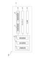
図1に示す通り、実施形態の生体状態モニタリングシステム1000は、荷重検出部200、制御部400、記憶部500を主に有する。荷重検出部200は、A/D変換部300を介して制御部400に接続されている。制御部400には、表示部600、報知部700、入力部800が接続されている。As shown in FIG. 1, the biological
荷重検出部200は、4つの荷重検出器LS1、LS2、LS3、LS4を備える。荷重検出器LS1~LS4のそれぞれは、例えばビーム形のロードセルを用いて荷重を検出する荷重検出器である。このような荷重検出器は例えば、特許第4829020号や特許第4002905号に記載されている。荷重検出器LS1~LS4はそれぞれ、配線又は無線によりA/D変換部300に接続されている。The
図2に示す通り、荷重検出部200の4つの荷重検出器LS1~LS4は、ベッドBDの四隅の脚の下端のキャスターCTの下にそれぞれ配置される。As shown in FIG. 2, the four load detectors LS1 to LS4 of the
A/D変換部300は、荷重検出部200からのアナログ信号をデジタル信号に変換するA/D変換器を備える。A/D変換部300は制御部400に配線又は無線で接続されている。The A/
制御部400は、専用又は汎用のコンピュータであり、内部に重心位置算出部410と生体情報取得部420とが構築されている。重心位置算出部410は荷重検出部200からの出力に基づいて被験者の重心の位置を算出する。生体情報取得部420は、荷重検出部200からの出力及び被験者の重心の位置に基づいて被験者の生体情報を算出する。The
記憶部500は、生体情報モニタリングシステム1000において使用されるデータを記憶する記憶装置であり、例えばハードディスク(磁気ディスク)を用いることができる。The
表示部600は、制御部400の生体情報取得部420から出力される情報を生体情報モニタリングシステム1000の使用者に表示する液晶モニタ等の画像表示装置である。The
報知部700は、制御部400からの指示に応じて所定の報知を聴覚的に行う装置、例えばスピーカを備える。The
入力部800は、制御部400に対して所定の入力を行うためのインターフェイスであり、キーボード及びマウスにし得る。The
生体情報モニタリングシステム1000による生体情報のモニタリングは、図3のフローチャートに示す通り、被験者の荷重を検出する荷重検出工程S1と、検出した荷重(荷重値、検出値)に基づいて被験者の重心の位置を算出する重心位置算出工程S2と、被験者の荷重及び/又は被験者の重心位置に基づいて被験者の生体情報(呼吸数等)を求める生体情報取得工程S3と、取得した被験者Sの生体情報を表示する表示工程S4とを主に含む。As shown in the flowchart of FIG. 3, the monitoring of biological information by the biological
荷重検出工程S1では、荷重検出器LS1~LS4を用いてベッドBD上の被験者Sの荷重を検出する。ベッドBD上の被験者Sの荷重は、ベッドBDの四隅の脚の下に配置された荷重検出器LS1~LS4に分散して付与され、これらによって分散して検出される。In the load detection process S1, the load of the subject S on the bed BD is detected using load detectors LS1 to LS4. The load of the subject S on the bed BD is distributed and applied to the load detectors LS1 to LS4 arranged under the legs at the four corners of the bed BD, and is detected in a distributed manner by these.
荷重検出器LS1~LS4はそれぞれ、荷重(荷重変化)を検出してアナログ信号としてA/D変換部300に出力する。A/D変換部300は、サンプリング周期を例えば5ミリ秒として、アナログ信号をデジタル信号に変換し、デジタル信号(以下「荷重信号」)として制御部400に出力する。以下では、荷重検出器LS1、LS2、LS3、LS4から出力されたアナログ信号をA/D変換部300においてデジタル変換して得られる荷重信号を、それぞれ荷重信号s1、s2、s3、s4と呼ぶ。 Each of the load detectors LS1 to LS4 detects a load (load change) and outputs the load as an analog signal to the A/
重心軌跡算出工程S2では、重心位置算出部410が、荷重検出器LS1~LS4からの荷重信号s1~s4に基づいてベッドBD上の被験者Sの重心Gの位置G(X、Y)を所定の周期T(例えば上記のサンプリング周期である5ミリ秒に等しい)で算出し、被験者Sの重心Gの位置の時間的変動(重心軌跡GT)を求める。ここで、(X、Y)は、ベッドBDの中心部を原点Oとして幅方向にXを、長さ方向にYを取ったXY座標面上における座標を示す(図2)。 In the center of gravity trajectory calculation process S2, the center of gravity
重心位置算出部410による重心Gの位置G(X、Y)の算出は、次の演算により行われる。すなわちG(X、Y)は、荷重検出器LS1、LS2、LS3、LS4の座標をそれぞれ(X1、Y1)、(X2、Y2)、(X3、Y3)、(X4、Y4)、荷重検出器LS1、LS2、LS3、LS4の荷重の検出値をそれぞれW1、W2、W3、W4として、次式により算出される。

重心位置算出部410は、上記の数式1、数式2に基づいて重心Gの位置G(X、Y)を所定のサンプリング周期Tで算出しながら、重心Gの位置G(X、Y)の時間的変動、即ち重心軌跡GTを求め、例えば記憶部500に記憶させる。The center of gravity
生体情報取得工程S3では、生体情報取得部420が、A/D変換部300から受け取る荷重信号s1~s4、重心位置算出工程S2で算出した重心Gの位置、重心軌跡GT等を用いて被験者Sの生体情報を取得する。 In the biometric information acquiring step S3, the biometric
取得される生体情報は例えば呼吸数及び心拍数である。生体情報取得部420が被験者の呼吸数及び心拍数を取得する方法の一例は次の通りである。The acquired biometric information is, for example, the respiratory rate and heart rate. An example of the method in which the biometric
人間の呼吸は、1分間に約12~20回程度行われるため、人間の呼吸の周波数は0.2~0.33Hz程度である。したがって、荷重信号s1~s4のいずれか1つについてフーリエ解析等の周波数解析を行えば、0.2~0.33Hzの周波数帯域において、被験者Sの呼吸の周波数に対応する位置に周波数ピークが現れる。生体情報取得部420は、当該周波数帯域に現れた周波数ピークの位置に基づいて被験者Sの呼吸数を取得してもよい。 Since a human breathes about 12 to 20 times per minute, the frequency of the human breath is about 0.2 to 0.33 Hz. Therefore, if a frequency analysis such as a Fourier analysis is performed on any one of the load signals s1 to s4 , a frequency peak appears at a position corresponding to the breathing frequency of the subject S in a frequency band of 0.2 to 0.33 Hz. The
同様に、人間の心拍は、1分間に30~200回程度行われるため、人間の心拍の周波数は0.5~3.3Hz程度である。したがって、荷重信号s1~s4のいずれか1つについてフーリエ解析等の周波数解析を行えば、0.5~3.3Hzの周波数帯域において、被験者Sの呼吸の周波数に対応する位置に周波数ピークが現れる。生体情報取得部420は、当該周波数帯域に現れた周波数ピークの位置に基づいて被験者Sの心拍数を取得してもよい。 Similarly, the human heart beats about 30 to 200 times per minute, and therefore the frequency of the human heart beat is about 0.5 to 3.3 Hz. Therefore, if a frequency analysis such as a Fourier analysis is performed on any one of the load signals s1 to s4 , a frequency peak appears at a position corresponding to the breathing frequency of the subject S in the frequency band of 0.5 to 3.3 Hz. The
生体情報取得部420が被験者の呼吸数及び心拍数を取得する方法の他の一例は次の通りである。Another example of a method in which the biometric
人間の呼吸は、胸郭及び横隔膜を移動させて、肺を膨張及び収縮させることにより行われる。ここで吸気時、すなわち肺が膨張する時には横隔膜は下方に下がり、内臓も下方に移動する。一方で呼気時、すなわち肺が収縮する時には横隔膜は上方に上がり、内臓も上方に移動する。本件の出願人に付与された特許第6105703号の明細書に記載されている通り、この内臓移動に伴って重心Gはわずかに振動(以下、「呼吸振動」と呼ぶ)し、その振動方向は背骨の延在方向(体軸方向)にほぼ沿っている。Human breathing is achieved by moving the rib cage and diaphragm to expand and contract the lungs. When inhaling, i.e., when the lungs expand, the diaphragm moves downward and the internal organs also move downward. On the other hand, when exhaling, i.e., when the lungs contract, the diaphragm moves upward and the internal organs also move upward. As described in the specification of Patent No. 6105703 granted to the applicant of this case, this movement of the internal organs causes the center of gravity G to vibrate slightly (hereinafter referred to as "respiratory vibration"), and the direction of this vibration is approximately along the extension direction of the spine (body axis direction).
したがって、生体情報取得部42は、重心軌跡GTに含まれる重心Gの呼吸振動の軌跡を特定し、特定された軌跡に含まれる極値点の数に基づいて被験者Sの呼吸数を取得してもよい。Therefore, the biometric information acquisition unit 42 may identify the trajectory of respiratory vibration of the center of gravity G contained in the center of gravity trajectory GT, and acquire the respiratory rate of the subject S based on the number of extreme points contained in the identified trajectory.
表示工程S4においては、制御部400が、生体情報取得部420が取得した生体情報を表示部600に表示させる。In the display step S4, the
また表示工程S4では、表示部600を用いた表示に加えて、又はこれに代えて、報知部700を用いた報知を行っても良い。この場合は例えば、被験者Sの呼吸数が所定値以下となった時に報知音を発し、被験者Sの呼吸の低下を生体情報取得システム1000の使用者である看護師や介護士等に報せる。In addition, in the display step S4, in addition to or instead of display using the
[体重管理装置100]
次に、本発明の実施形態の体重管理装置100について、図4~図6を参照して説明する。[Weight Management Device 100]
Next, the body
図4、図5に示す通り、体重管理装置100は、筐体10と、筐体10の内部に収容された制御部20及び記憶部30と、筐体10の前面10fに設けられたディスプレイ40及び入力部50と、筐体10の後面10rに設けられた取付部60とを主に有する。筐体10の下面10dには、生体情報モニタリングシステム1000と体重管理装置100とを繋ぐ配線Wが接続されている。As shown in Figures 4 and 5, the
以下の説明において、前面10fを前側から見た場合の右側、左側、上側、下側をそれぞれ、体重管理装置100の右側、左側、上側、下側と呼ぶ。In the following description, the right side, left side, upper side, and lower side of the
筐体10は、樹脂(一例としてABS)により形成された略直方体の箱である。図4(a)においては、後面10rと側面との間の縁のみが丸みを有するように描かれているがこれには限られず、所望の縁が丸みを有し得る。また、前面10f、後面10r等の各面の1つ又は複数が凸状又は凹状の曲面であってもよい。The
制御部20は、専用又は汎用のコンピュータである。制御部20には、体重算出部21、表示制御部22、及び報知制御部23が構築されている。体重算出部21、表示制御部22、及び報知制御部23の動作の内容については後述する。The
記憶部30は、体重管理装置100において使用されるデータを記憶する記憶装置である。記憶部30は、短期記憶領域31と長期記憶領域32とを有する。短期記憶領域31と長期記憶領域32とは、いずれもRAMやフラッシュメモリ等であってよい。The
ディスプレイ40は、制御部20の体重算出部21により算出された被験者の体重を表示する。ディスプレイ40は一例として液晶ディスプレイであってよい。本実施形態のディスプレイ40は、筐体10の前面10fの上から三分の一程度の領域に配置された横長の液晶ディスプレイである。The
入力部50は、制御部20に対して所定の入力を行うためのインターフェイスである。本実施形態の入力部50は、筐体10の前面10fの下から三分の二程度の領域に三段に配置された7つの押しボタンにより構成されている。The
入力部50を構成する7つの押しボタンは、上段中央に配置されたゼロボタンB1、上段右に配置された記録ボタンB2、中段左に配置された履歴ボタンB3、中段中央に配置された送りボタンB4、中断右に配置された戻りボタンB5、下段左に配置された設定ボタンB6、及び設定ボタンB6の右側に配置された停止ボタンB7を含む。停止ボタンB7は、ほかのボタンよりも大きい。停止ボタンB7の一部は、筐体10の前面10fの左右中央に位置している。The seven push buttons that make up the
入力部50のボタンB1~B7は、制御部20に所定の指示を与えるように制御部20に接続されている。体重管理装置100の使用者は、入力部50のボタンB1~B7を操作して、体重管理装置100の制御部20に指示を与えることができる(詳細後述)。Buttons B1 to B7 of the
取付部60は、体重管理装置100をベッドBDに着脱可能に取り付けるための止め具である。本実施形態では、取付部60は樹脂製であり、平板を略U字状に湾曲させた形状を有する。The
図4(b)に示すように、取付部60は、矩形の平板部60aと、平板部60aの長手方向の一端側から側面視弧状に延びて平板部60aの長手方向他端側へと折り返す湾曲部60bと、湾曲部60bの端部から側面視弧状に延びて平板部60aから離間する折返部60cとを含む。平板部60aと湾曲部60bとにより囲まれた領域に保持領域HAが画定される。As shown in FIG. 4(b), the mounting
取付部60は、平板部60aを貫通して前後方向に延びるピン60pにより筐体10の後面10rに取り付けられている。取付部60はピン60pを中心として枢動可能である。The mounting
次に、体重管理装置100を生体状態モニタリングシステム1000と共に用いて、ベッドBD上の被験者Sの体重管理をベッドサイドで行う方法を説明する。Next, we will explain how to use the
(1)体重管理装置100のベッドBDへの取り付け
体重管理装置100及び生体情報モニタリングシステム1000の使用者(例えば医師や看護師、介護従事者等である)は、まず、体重管理装置100を生体情報モニタリングシステム1000に接続し、体重管理装置100をベッドBDに着脱可能に取り付ける。(1) Attaching the
体重管理装置100の生体情報モニタリングシステム1000への接続は、例えば、配線WをA/D変換部300に接続することによりなされる。これにより、荷重信号s1~s4が体重管理装置100の制御部20に送られる。体重管理装置100と生体情報モニタリングシステム1000との接続は無線によりなされてもよい。 The body
体重管理装置100のベッドBDへの取り付けは、例えば、体重管理装置100の取付部60の保持領域HAに柵Rを配置させて、体重管理装置100をベッドBDの柵Rに着脱可能に取り付けることによりなされる(図6(a)、図6(b))。The
体重管理装置100は、ベッドBDの柵Rに取り付けられた状態において、ベッドBDに相対して移動可能である。具体的には、体重管理装置100は、柵Rの延びる方向を軸方向として枢動可能であり、且つピン60pを軸方向として(即ち体重管理装置100の前後方向を軸方向として)枢動可能である。したがって体重管理装置100の使用者は、体重管理装置100をベッドBDの柵Rに取り付けたまま、ディスプレイ40の向き(ディスプレイ40の法線方向及びディスプレイの上下方向)を、ディスプレイの視認に適した方向に調整することができる。When attached to the railing R of the bed BD, the
(2)体重の算出、及び体重の表示
生体状態モニタリングシステム1000に接続された状態において、制御部20の体重算出部21は、生体状態モニタリングシステム1000のA/D変換部300からの荷重信号s1~s4に基づいて被験者Sの体重を算出する。被験者Sの体重の算出は、例えば、荷重信号s1~s4が示す荷重値を和算することにより行う。(2) Calculation of weight and display of weight
When connected to the biological
制御部20の表示制御部22は、体重算出部21において算出された被験者Sの体重を、ディスプレイ40に表示するとともに、記憶部30の短期記憶領域31に記憶させる。The
本実施形態においては、体重の算出及び表示は、所定の周期(任意であるが、一例として1秒)で継続的に実行される。即ち、体重算出部21は所定の周期で体重の算出を行い、表示制御部22は算出された体重を逐次ディスプレイ40に表し、且つ記憶部30の短期記憶領域31に記憶させる。そのため、ディスプレイ40に表示される体重の値は、所定の周期で最新の値に更新される。短期記憶領域31に記憶された体重は所定期間経過後に消去されてもよい。In this embodiment, the calculation and display of weight is performed continuously at a predetermined cycle (which may be any cycle, but for example, every second). That is, the
使用者は、体重管理装置100のディスプレイ40を視認するだけで、被験者Sの現在の体重を容易に確認することができる。The user can easily check the current weight of the subject S simply by looking at the
(3)端坐位判定、及び離床判定
制御部20の報知制御部23は、体重算出部21が所定の周期で算出する被験者Sの体重の変動量に基づいて、所定の報知を行う。(3) Determination of Sitting Position and Getting Out of Bed The
報知制御部23は、具体的には、体重算出部21が最新の体重を算出するたびに、過去の体重(一例として最新の体重よりも一周期前に算出された体重。他の一例として数秒前に算出された体重)からの減少量を算出する。そして、算出した減少量を所定の閾値thと比較し、減少量が閾値thよりも大きい場合には、通信部(不図示)を介して、使用者が携帯する端末等に視覚的な報知及び/又は聴覚的な報知を行わせる。Specifically, the
例えば閾値thが20kg程度である場合は、体重算出部21が算出する被験者Sの体重が20kg程度減少した場合に使用者に対して所定の報知がなされる。閾値thが5kg程度である場合は、体重算出部21が算出する被験者Sの体重が5kg程度減少した場合に使用者に対して所定の報知がなされる。For example, if the threshold th is about 20 kg, a predetermined notification is given to the user when the weight of the subject S calculated by the
一周期(ここでは1秒)や数秒程度の短時間での体重の算出値の20kgを越える変動は、一般に、被験者SがベッドBDから離れた状態(即ち、離床状態)に至った場合に生じ得る。また、一周期(ここでは1秒)や数秒程度の短時間での体重の算出値の5kgを越える変動は、一般に、被験者がベッドの端部に座って足を床につけた状態(いわゆる端座位状態)に至った場合に生じ得る。A change in the calculated weight of more than 20 kg in one cycle (here, 1 second) or a short period of time such as a few seconds can generally occur when the subject S leaves the bed BD (i.e., gets out of bed). Also, a change in the calculated weight of more than 5 kg in one cycle (here, 1 second) or a short period of time such as a few seconds can generally occur when the subject sits on the edge of the bed with his or her feet on the floor (the so-called edge sitting position).
したがって、使用者は、閾値thを20kg程度に設定することで、被験者Sが離床状態に至ったと推測される場合に報知制御部23に報知を行わせることができる。また使用者は、、閾値thを5kg程度に設定することで、被験者Sが端坐位状態に至ったと推測される場合に報知制御部23に報知を行わせることができる。Therefore, by setting the threshold value th to approximately 20 kg, the user can have the
使用者は、入力部60を用いて閾値thの値を設定できる。具体的には例えば、入力部50の設定ボタンB6を押して閾値thを設定可能な状態とし、送りボタンB4を押すことで閾値thを大きくし、戻りボタンB5を押すことで閾値thを小さくする。また使用者は、自らの携帯する端末が報知制御部23からの通知を受けてなんらかの報知動作を行っている場合、体重管理装置100の入力部50の停止ボタンB7を押して当該報知動作を停止(終了)することができる。The user can set the value of the threshold th using the
また、報知制御部23は、停止ボタンB7が所定の間、押し続けられた場合には、体重減少量と閾値thとの比較に基づく報知を一定の期間だけ中止するように構成されている。使用者は、被験者SがベッドBDを離れることがあらかじめ分かっている場合は、停止ボタンB7が所定の間押し続けて報知を中止させ、不要な報知を回避できる。The
(4)ゼロリセット
体重管理装置100の使用者は、入力部50のゼロボタンB1を押すことにより、体重算出部21における算出値をゼロリセットすることができる。即ち、ゼロボタンB1が押された時刻において加えられている荷重が風袋引きされる。ベッドBD上に被験者Sが存在しない状態でゼロボタンB1を押してゼロリセットを実行した上で被験者SをベッドBD上に移動させることで、誤差要因の影響を抑制して、被験者Sの体重をより正確に算出することができる。(4) Zero Reset A user of the body
(5)体重の記録、及び履歴の表示
体重管理装置100の使用者は、入力部50の記録ボタンB2を押すことにより、記録ボタンB2を押した時刻における被験者Sの体重を記録することができる。また使用者は、入力部50の履歴ボタンB3、送りボタンB4、及び、戻りボタンB5を押すことにより、記録した被験者Sの体重をディスプレイ40に表示することができる。具体的には次の通りである。(5) Recording weight and displaying history By pressing the record button B2 on the
使用者が入力部50の記録ボタンB2を押した時、制御部20の表示制御部22は、体重算出部21が算出した被験者Sの体重の内、記録ボタンB2が押された時刻における最新の値を、第1記録値RV1として長期記憶領域32に記憶させる。この時、表示制御部22は、第1記録値RV1を、記録ボタンB2が押された日時(日付及び時刻)と関連づけた状態で長期記憶領域32に記憶させる。 When the user presses the record button B2 of the
使用者が入力部50の記録ボタンB2を押す度に、同様の記録が実行される。第1記録値RV1が既に記録された状態で記録ボタンB2が押された場合には、長期記憶領域32には第2記録値RV2が記録される。即ち、第N記録値RVNが既に記録された状態で記録ボタンB2が押された場合には、長期記憶領域32には第N+1記録値RVN+1が記録される。Nの値の上限は任意であるが、一例として7~10程度であってよい。 Similar recording is performed each time the user presses the record button B2 of the
少なくとも第1記録値RV1が長期記憶領域32に記憶されている状態で、使用者が入力部50の履歴ボタンB3を押した時、制御部20の表示制御部22は、長期記憶領域32に記憶された記録値を、当該記録値に関連付けられた日時と共にディスプレイ40に表示する。When at least the first recorded value RV1 is stored in the long-
また、長期記憶領域32に複数の記録値が記憶されている場合は、表示制御部22は、送りボタンB4が押された時にディスプレイ40に表示する記録値を1つ古い記録値に切り替え、戻りボタンB5が押された時にディスプレイ40に表示する記録値を1つ新しい記録値に切り替える。即ち、第N記録値RVNがディスプレイ40に表示された状態で送りボタンB4を押せばディスプレイ40の表示は第N-1記録値RVNー1に切り替わり、戻りボタンB5を押せばディスプレイ40の表示は第N+1記録値RVN+1に切り替わる。 Furthermore, when a plurality of recorded values are stored in the long-
なお、第N記録値RVNとして記憶される値は記録ボタンB2が押された時刻における最新の値には限られず、記録ボタンB2が押された時刻と所定の対応関係を有する所定のタイミング(一例として、記録ボタンB2が押された時刻から前又は後ろに所定時間シフトしたタイミング等)における値であってもよい。 The value stored as the Nth recorded valueRVN is not limited to the latest value at the time when the record button B2 is pressed, but may be a value at a predetermined timing having a predetermined correspondence with the time when the record button B2 is pressed (for example, a value at a timing shifted a predetermined time before or after the time when the record button B2 is pressed).
(6)体重変化量の算出
体重管理装置100の使用者は、入力部50の記録ボタンB2と設定ボタンB6を操作して第1の時刻における被験者Sの体重と、第1の時刻よりも後の第2の時刻における被験者の体重の差分を算出することができる。(6) Calculation of weight change A user of the
具体的には例えば、使用者は、設定ボタンB6を押して差分算出モードとし、第1の時刻に記録ボタンB2を押す。これにより、表示制御部B22が第1の時刻の直前に算出された被験者Sの体重を第1体重として記憶部30の所定の領域に記憶させる。その後、使用者が第2の時刻に記録ボタンB2を押すと、表示制御部B22は第2の時刻の直前に算出された第2体重と、記憶部30に記憶させた第1体重との差分を算出し、算出値をディスプレイ40に表示する。Specifically, for example, the user presses the setting button B6 to enter the difference calculation mode, and presses the record button B2 at the first time. This causes the display control unit B22 to store the weight of the subject S calculated immediately before the first time in a specified area of the
なお、第1、第2体重として記憶される値は第1、第2の時刻の直前に算出された値には限られず、第1、第2の時刻と所定の対応関係を有する所定のタイミング(一例として、第1、第2の時刻から前又は後ろに所定時間シフトしたタイミング等)における値であってもよい。The values stored as the first and second weights are not limited to values calculated immediately before the first and second times, but may be values at a specified timing having a specified correspondence with the first and second times (for example, a timing shifted a specified time before or after the first and second times).
本実施形態の体重管理装置100の効果を以下にまとめる。The effects of the
本実施形態の体重管理装置100は、取付部60を介して、ベッドBDに着脱可能に取り付けられている。したがって使用者は、ベッドBD上の被験者Sの体重を、ベッドサイドにて容易に管理することができる。The
具体的には、体重管理装置100がベッドBDに対して着脱可能であるため、使用者は、体重管理装置100を自らの使用に適した高さまで持ち上げることができる。そして自らの使用に適した位置で、ディスプレイ40を視認し、入力部50を操作することができる。Specifically, because the
また、本実施形態の体重管理装置100は、取付部60を介してベッドBDに取り付けた状態においても、ディスプレイ40の法線方向が可変となるように構成されている。したがって使用者は、体重管理装置100をベッドBDから取り外さない場合でも、ディスプレイ40を視認しやすい向きとして、ディスプレイ40を良好に視認し、入力部50を容易に操作することができる。The
本実施形態の体重管理装置100においては、入力部50の停止ボタンB7は、その一部が筐体10の前面10fの左右中央に位置するように配置されている。したがって使用者は、筐体10を右手及び左手のいずれで把持した場合でも、容易に親指で停止ボタンB7を押すことができる。In the
<変形例>
上記実施形態の体重管理装置100において、次の変形態様を採用することもできる。<Modification>
The body
上記実施形態の体重管理装置100において、報知制御部23は、報知を行った場合、報知内容と報知日時を長期記憶領域32に記憶させるよう構成されていてもよい。また、表示制御部22は、入力部50からの入力に応じて記憶された報知内容及び報知日時を報知履歴としてディスプレイ40に表示するように構成されていてもよい。In the
上記実施形態の体重管理装置100においては、制御部20に体重算出部21、表示制御部22、及び報知制御部23が構築されているがこれには限られない。制御部20においては、体重算出部21、表示制御部22、報知制御部23の1つ以上を有さなくてもよい。In the
この場合、体重算出部21、表示制御部22、及び報知制御部23のうち制御部20が有さない構成の機能は、生体情報モニタリングシステム1000(具体的には例えば、A/D変換部300、制御部400等)に行わせてもよい(即ち、生体状態モニタリングシステム1000が、体重算出部21、表示制御部22、及び報知制御部23の少なくとも1つを備えてもよい)。また、制御部20の機能を全て生体情報モニタリングシステム1000(具体的には例えば、A/D変換部300、制御部400等)に行わせて制御部20を省略してもよい(即ち、生体状態モニタリングシステム1000が制御部20を備えてもよい)。In this case, the functions of the components of the
上記実施形態の体重管理装置100において、記憶部30及び/又は入力部50を省略してもよい。記憶部30は、生体状態モニタリングシステム1000が備えてもよい。In the
上記実施形態の管理装置100においては取付部60はベッドBDの柵Rに引っ掛けられる側面視略U字状の板状部材であるがこれには限られない。取付部60は、筐体10をベッドBDに対して着脱可能に取り付けられることのできる任意の構造とし得る。In the
具体的には例えば、取付部60として、ベッドBDの柵Rを挟持するクリップ状の部材や、ベッドBDの柵Rに磁力により取り付けられる磁気部材を用い得る。また取付部60と筐体10との接続をボールジョイントにより行い取付部60に対する筐体10の姿勢変化の自由度を高めてもよい。Specifically, for example, the
ベッドBDに対する体重管理装置100の取付位置は柵Rに限られず任意である。例えば、ベッドBDのヘッドボードHB(図5)、フットボードFB(図5)、ベッドの脚等に体重管理装置100を着脱可能に取り付けてもよい。The attachment position of the
上記実施形態の体重管理装置100において、入力部50の各ボタンに追加的な機能を与えてもよい。具体的には例えば、停止ボタンB7に、ナースコール等を停止させる機能を与えてもよい。或いは、ベッドBDがリクライニング機能を有する場合は、送りボタンB4と戻りボタンB5にベッドBDの昇降動作を行わせる機能を与えてもよい。In the
上記実施形態においては、体重管理装置100を生体状態モニタリングシステム1000の外部の装置として説明を行った。しかしながら、体重管理装置100を生体状態モニタリングシステム1000の一部と捉えることもできる。In the above embodiment, the
上記実施形態の生体情報モニタリングシステム1000は、必ずしも荷重検出器LS1~LS4の全てを備える必要はなく、このいずれか一つを備えるのみでもよい。また、荷重検出器は、必ずしもベッドの四隅に配置される必要はなく、ベッド上の被験者の荷重及びその変動を検出しうるように、任意の位置に配置し得る。また、荷重検出器LS1~LS4は、ビーム形ロードセルを用いた荷重センサに限られず、例えばフォースセンサを使用することもできる。The biological
上記実施形態の生体情報モニタリングシステム1000においては、荷重検出器LC1~LC4の各々は、ベッドBDの脚の下端に取り付けられたキャスターCTの下に配置されていたがこれには限られない。荷重検出器LS1~LS4の各々は、ベッドBDの4本の脚とベッドBDの床板との間に設けられてもよいし、ベッドBDの4本の脚が上下に分割可能であれば、上部脚と下部脚との間に設けられても良い。In the above embodiment of the biological
上記実施形態の生体情報モニタリングシステム1000においては、ベッド上に横たわる被験者の下方、一例としてシーツの下にマトリックス状に配置された多数の感圧センサ(圧力センサ)により荷重検出部200を構成することもできる。この態様においては、多数の感圧センサの出力に基づいて、被験者の重心の位置を求めることができる。In the biological
荷重検出部200とベッドBDを一体に又は着脱可能に組み合わせて、ベッドBDと上記実施形態の生体情報モニタリングシステム1000とからなるベッドシステムを構成してもよい。The
上記実施形態の生体情報モニタリングシステム1000において、荷重検出部200とA/D変換部300との間に、荷重検出部200からの信号を増幅する信号増幅部や、信号からノイズを取り除くフィルタリング部を設けても良い。In the biological
上記実施形態の生体情報モニタリングシステム1000において、表示部600は、モニタに代えて、又はこれに加えて、生体情報を表わす情報を印字して出力するプリンタや、生体情報を表示するランプ等の簡易な視覚表示手段を備えてもよい。報知部7はスピーカに代えて、又はこれに加えて、振動により報知を行う振動発生部を備えてもよい。In the biological
本発明の特徴を維持する限り、本発明は上記実施の形態に限定されるものではなく、本発明の技術的思想の範囲内で考えられるその他の形態についても、本発明の範囲内に含まれる。As long as the characteristics of the present invention are maintained, the present invention is not limited to the above-described embodiment, and other forms that are conceivable within the scope of the technical concept of the present invention are also included within the scope of the present invention.
本発明の体重管理装置によれば、被験者の体重をベッドサイドにおいて容易且つ高い操作性で管理することができる。The weight management device of the present invention allows the subject's weight to be managed easily and with high operability at the bedside.
10 筐体、21 体重算出部、22 表示制御部、23 報知制御部、30 記憶部、40 ディスプレイ、50 入力部、100 体重管理装置、LS1,LS2,LS3,LS4 荷重検出器、300 A/D変換部、400 制御部、410 重心位置算出部、420 生体情報取得部、500 記憶部、600 表示部、700 報知部、800 入力部、1000 生体情報モニタリングシステム、BD ベッド、S 被験者10 Housing, 21 Weight calculation unit, 22 Display control unit, 23 Notification control unit, 30 Memory unit, 40 Display, 50 Input unit, 100 Weight management device, LS1, LS2, LS3, LS4 Load detector, 300 A/D conversion unit, 400 Control unit, 410 Center of gravity position calculation unit, 420 Biometric information acquisition unit, 500 Memory unit, 600 Display unit, 700 Notification unit, 800 Input unit, 1000 Biometric information monitoring system, BD Bed, S Subject
Claims (6)
Translated fromJapanese筐体と、
前記筐体の外面に設けられ、且つ前記検出値に基づく前記被験者の体重を表示するディスプレイと、
前記筐体の外面に設けられ、且つ前記ベッドに着脱可能である取付部と、
入力部と、
前記ディスプレイの表示内容を制御する表示制御部とを備え、
前記体重管理装置又は前記生体情報モニタリングシステムが、所定期間における前記被験者の体重の変化量と前記入力部を介して設定された閾値との比較に基づいて、前記被験者の生体情報に関する報知を行う報知制御部を備え、
前記入力部は記録ボタンを有し、
前記表示制御部は、
第1時刻に前記記録ボタンが操作された時に、第1時刻に対応する前記被験者の第1体重を記憶部に記憶させ、
第1時刻よりも後の第2時刻に前記記録ボタンが操作された時に、第2時刻に対応する前記被験者の第2体重を前記記憶部に記憶させ、
前記第1体重と前記第2体重との差分を前記ディスプレイに表示する体重管理装置。 1. A body weight management device for use in a biological information monitoring system that monitors biological information of a subject on a bed based on a detection value of a load detector that detects the load of the subject,
A housing and
a display provided on an outer surface of the housing and displaying the weight of the subject based on the detected value;
An attachment portion provided on an outer surface of the housing and detachable from the bed;
An input unit;
A display control unit that controls the display content of the display,
the body weight management device or the biological information monitoring system includes a notification control unit that performs a notification regarding the biological information of the subject based on a comparison between an amount of change in the body weight of the subject over a predetermined period of time and a threshold value set via the input unit,
the input unit has a record button,
The display control unit is
When the record button is operated at a first time, a first weight of the subject corresponding to the first time is stored in a storage unit;
when the record button is operated at a second time that is later than the first time, a second weight of the subject corresponding to the second time is stored in the storage unit;
A weight management devicethat displays a difference between the first weight and the second weight on the display .
前記停止ボタンが前記筐体の幅方向の中央部に設けられている請求項1~3のいずれか一項に記載の体重管理装置。 Further comprising a stop button for stopping the notification,
The body weight management device according toany one of claims 1 to 3 , wherein the stop button is provided at a center portion in a width direction of the housing.
前記表示制御部は、
前記記録ボタンが操作された時刻と当該時刻に対応する前記被験者の体重とを関連付けて前記記憶部に記憶させ、
前記履歴ボタンが操作された時に、前記記憶部に記憶させた前記被験者の体重を関連付けられた時刻と共に前記ディスプレイに表示する請求項1~4のいずれか一項に記載の体重管理装置。Further equipped with ahistorybutton ,
The display control unit is
a time when therecord button is operated and a weight of the subject corresponding to the time are stored inthe storage unit in association with each other;
5. The weight management device according to claim 1 , wherein when the history button is operated, the weight of the subject stored in the memory unit is displayed on the display together with the associated time.
前記荷重検出器の検出値に基づいて前記被験者の生体情報を取得する生体情報取得部と、
請求項1~5のいずれか一項に記載の体重管理装置とを備える生体情報モニタリングシステム。 a load detector for detecting the load of a subject on the bed;
a biometric information acquiring unit that acquires biometric information of the subject based on a detection value of the load detector;
A biological information monitoring system comprising the weight management device according to any one of claims 1 to5 .
Priority Applications (5)
| Application Number | Priority Date | Filing Date | Title |
|---|---|---|---|
| JP2020190685AJP7570895B2 (en) | 2020-11-17 | 2020-11-17 | Weight management device and biological information monitoring system |
| US18/252,085US20230408324A1 (en) | 2020-11-17 | 2021-11-05 | Weight management device and biological information monitoring system |
| PCT/JP2021/040829WO2022107623A1 (en) | 2020-11-17 | 2021-11-05 | Weight management device and biological information monitoring system |
| EP21894497.3AEP4249862A4 (en) | 2020-11-17 | 2021-11-05 | WEIGHT MANAGEMENT DEVICE AND BIOLOGICAL INFORMATION MONITORING SYSTEM |
| CN202180088698.5ACN116802462A (en) | 2020-11-17 | 2021-11-05 | Weight management device and biological information monitoring system |
Applications Claiming Priority (1)
| Application Number | Priority Date | Filing Date | Title |
|---|---|---|---|
| JP2020190685AJP7570895B2 (en) | 2020-11-17 | 2020-11-17 | Weight management device and biological information monitoring system |
Publications (2)
| Publication Number | Publication Date |
|---|---|
| JP2022079850A JP2022079850A (en) | 2022-05-27 |
| JP7570895B2true JP7570895B2 (en) | 2024-10-22 |
Family
ID=81708811
Family Applications (1)
| Application Number | Title | Priority Date | Filing Date |
|---|---|---|---|
| JP2020190685AActiveJP7570895B2 (en) | 2020-11-17 | 2020-11-17 | Weight management device and biological information monitoring system |
Country Status (5)
| Country | Link |
|---|---|
| US (1) | US20230408324A1 (en) |
| EP (1) | EP4249862A4 (en) |
| JP (1) | JP7570895B2 (en) |
| CN (1) | CN116802462A (en) |
| WO (1) | WO2022107623A1 (en) |
Citations (7)
| Publication number | Priority date | Publication date | Assignee | Title |
|---|---|---|---|---|
| JP2002027355A (en) | 2000-07-04 | 2002-01-25 | Matsushita Electric Ind Co Ltd | Television receiver with video tape recorder |
| JP2004024370A (en) | 2002-06-24 | 2004-01-29 | Matsushita Electric Ind Co Ltd | bed |
| US20060101581A1 (en) | 2004-10-29 | 2006-05-18 | Blanchard Frederick W | Patient support apparatus |
| JP2011010915A (en) | 2009-07-03 | 2011-01-20 | Showa Denko Kk | Management system of leaving-bed information |
| JP2014147647A (en) | 2013-02-04 | 2014-08-21 | Nippon Koden Corp | Biological information monitor |
| JP2016529934A (en) | 2013-09-02 | 2016-09-29 | コーニンクレッカ フィリップス エヌ ヴェKoninklijke Philips N.V. | Bed rail mount |
| JP2020137722A (en) | 2019-02-27 | 2020-09-03 | パラマウントベッド株式会社 | Bed device |
Family Cites Families (9)
| Publication number | Priority date | Publication date | Assignee | Title |
|---|---|---|---|---|
| US4869266A (en)* | 1985-12-31 | 1989-09-26 | Stonecrest Systems, Inc. | Patient monitoring unit for surgical use |
| JPH0344163Y2 (en)* | 1988-07-20 | 1991-09-17 | ||
| JPH114820A (en)* | 1997-06-18 | 1999-01-12 | Ee D K:Kk | Health caring device |
| JP4788987B2 (en)* | 2001-09-27 | 2011-10-05 | アドバンスドメディカル株式会社 | bed |
| JP4002905B2 (en) | 2004-04-13 | 2007-11-07 | 日本圧着端子製造株式会社 | Load scale and load scale system using the same |
| JP4829020B2 (en) | 2006-07-10 | 2011-11-30 | 昭和電工株式会社 | Bed load detector |
| US9044367B2 (en)* | 2010-06-12 | 2015-06-02 | American Home Health Care, Inc. | Patient weighing and bed exit monitoring |
| US8475367B1 (en)* | 2011-01-09 | 2013-07-02 | Fitbit, Inc. | Biometric monitoring device having a body weight sensor, and methods of operating same |
| JP6105703B1 (en) | 2015-09-29 | 2017-03-29 | ミネベアミツミ株式会社 | Biological information monitoring system |
- 2020
- 2020-11-17JPJP2020190685Apatent/JP7570895B2/enactiveActive
- 2021
- 2021-11-05CNCN202180088698.5Apatent/CN116802462A/enactivePending
- 2021-11-05EPEP21894497.3Apatent/EP4249862A4/enactivePending
- 2021-11-05USUS18/252,085patent/US20230408324A1/enactivePending
- 2021-11-05WOPCT/JP2021/040829patent/WO2022107623A1/ennot_activeCeased
Patent Citations (7)
| Publication number | Priority date | Publication date | Assignee | Title |
|---|---|---|---|---|
| JP2002027355A (en) | 2000-07-04 | 2002-01-25 | Matsushita Electric Ind Co Ltd | Television receiver with video tape recorder |
| JP2004024370A (en) | 2002-06-24 | 2004-01-29 | Matsushita Electric Ind Co Ltd | bed |
| US20060101581A1 (en) | 2004-10-29 | 2006-05-18 | Blanchard Frederick W | Patient support apparatus |
| JP2011010915A (en) | 2009-07-03 | 2011-01-20 | Showa Denko Kk | Management system of leaving-bed information |
| JP2014147647A (en) | 2013-02-04 | 2014-08-21 | Nippon Koden Corp | Biological information monitor |
| JP2016529934A (en) | 2013-09-02 | 2016-09-29 | コーニンクレッカ フィリップス エヌ ヴェKoninklijke Philips N.V. | Bed rail mount |
| JP2020137722A (en) | 2019-02-27 | 2020-09-03 | パラマウントベッド株式会社 | Bed device |
Also Published As
| Publication number | Publication date |
|---|---|
| US20230408324A1 (en) | 2023-12-21 |
| WO2022107623A1 (en) | 2022-05-27 |
| EP4249862A4 (en) | 2024-10-16 |
| EP4249862A1 (en) | 2023-09-27 |
| JP2022079850A (en) | 2022-05-27 |
| CN116802462A (en) | 2023-09-22 |
Similar Documents
| Publication | Publication Date | Title |
|---|---|---|
| JP7303854B2 (en) | Evaluation device | |
| JP4342455B2 (en) | Health management device and health management system | |
| KR101188655B1 (en) | Pillow with apparatus for inference of sleeping status | |
| JP2019516454A (en) | Method and apparatus for determining the position and / or orientation of a wearable device on a subject | |
| CN108289779B (en) | Physical condition checking device, physical condition checking method, and bed system | |
| CN107949315B (en) | Abnormality notification system, abnormality notification method, and program | |
| JP6923426B2 (en) | Abnormality determination device and program used for it | |
| CN110913819A (en) | In-bed condition monitoring system | |
| JPH09294727A (en) | Calorie consumption measuring device | |
| CN109475322B (en) | Respiratory waveform tracing system | |
| CN111867470B (en) | Sleep/Wake Detection System | |
| JP3203145U (en) | Biological vibration detection device, bed with biological vibration detection device, and biological vibration data management system | |
| CN110996791B (en) | Physical activity determination system and biological state monitoring system | |
| JP2018126423A (en) | Bed monitoring system | |
| JP7570895B2 (en) | Weight management device and biological information monitoring system | |
| WO2011072416A1 (en) | Human body monitoring system and monitoring method using fabric sensors | |
| JP4423603B2 (en) | Biological data detection device | |
| JP6556783B2 (en) | Abnormality reporting system and program | |
| JP6535770B2 (en) | Biological information monitoring system | |
| JP7482842B2 (en) | Biometric information display system | |
| JP7409986B2 (en) | Biological condition monitoring system, bed system equipped with the same, and biological condition monitoring method | |
| JP2008220392A (en) | Biological information measuring apparatus | |
| CN111788614B (en) | In-bed state monitoring system and bed provided with same | |
| JP7496257B2 (en) | Biometric information acquisition system and sensor placement determination program | |
| JP2025065486A (en) | Judging device |
Legal Events
| Date | Code | Title | Description |
|---|---|---|---|
| A621 | Written request for application examination | Free format text:JAPANESE INTERMEDIATE CODE: A621 Effective date:20231012 | |
| A131 | Notification of reasons for refusal | Free format text:JAPANESE INTERMEDIATE CODE: A131 Effective date:20240430 | |
| A601 | Written request for extension of time | Free format text:JAPANESE INTERMEDIATE CODE: A601 Effective date:20240628 | |
| A521 | Request for written amendment filed | Free format text:JAPANESE INTERMEDIATE CODE: A523 Effective date:20240828 | |
| TRDD | Decision of grant or rejection written | ||
| A01 | Written decision to grant a patent or to grant a registration (utility model) | Free format text:JAPANESE INTERMEDIATE CODE: A01 Effective date:20240917 | |
| A61 | First payment of annual fees (during grant procedure) | Free format text:JAPANESE INTERMEDIATE CODE: A61 Effective date:20241009 | |
| R150 | Certificate of patent or registration of utility model | Ref document number:7570895 Country of ref document:JP Free format text:JAPANESE INTERMEDIATE CODE: R150 |