JP7570250B2 - Damper - Google Patents
DamperDownload PDFInfo
- Publication number
- JP7570250B2 JP7570250B2JP2021023540AJP2021023540AJP7570250B2JP 7570250 B2JP7570250 B2JP 7570250B2JP 2021023540 AJP2021023540 AJP 2021023540AJP 2021023540 AJP2021023540 AJP 2021023540AJP 7570250 B2JP7570250 B2JP 7570250B2
- Authority
- JP
- Japan
- Prior art keywords
- cylinder
- case
- axial direction
- damper
- hollow case
- Prior art date
- Legal status (The legal status is an assumption and is not a legal conclusion. Google has not performed a legal analysis and makes no representation as to the accuracy of the status listed.)
- Active
Links
Images


Landscapes
- Buildings Adapted To Withstand Abnormal External Influences (AREA)
- Vibration Prevention Devices (AREA)
- Fluid-Damping Devices (AREA)
Description
Translated fromJapanese本発明は、ダンパに関する。The present invention relates to a damper.
従来、基礎(下部構造体)上に、複数のゴム板と鋼板とが重ね合わされた積層ゴムを設けると共に鉛プラグ等のエネルギ吸収手段を設け、それらの上で建物(上部構造体)を免震支持する免震建物が知られている。
このような免震建物において、通常の設計で想定する地震動を超える大きな地震動(設計での想定を超える地震動)が生じた場合の建物(上部構造体)の過大な変位を制御する方法として、下部構造体と上部構造体との間に水平方向に延在するダンパをさらに設置する方法が考えられる。
しかしながら、非常に発生頻度、確率の低いと考えられる設計での想定を超える極大地震動に対応するためこのような方法にすると、より発生頻度、確率の高い地震に対してもダンパが減衰力を発揮してしまい、免震性能を低下させ、上部構造体へ不要な地震力を生じさせるという問題がある。 Conventionally, a seismically isolated building has been known in which a laminated rubber layer made of multiple rubber plates and steel plates is provided on a foundation (substructure), along with energy absorbing means such as lead plugs, and the building (superstructure) is supported on top of these in a seismic isolation manner.
In such seismically isolated buildings, one possible method of controlling excessive displacement of the building (superstructure) in the event of a large earthquake motion (earthquake motion exceeding the earthquake motion assumed in the design) that exceeds the earthquake motion assumed in the normal design is to further install a damper extending horizontally between the lower structure and the superstructure.
However, if this method is used to respond to extremely large earthquake motions that exceed the design assumptions and are considered to have an extremely low occurrence frequency and probability, the dampers will also exert their damping force against earthquakes that have a higher occurrence frequency and probability, reducing the seismic isolation performance and causing unnecessary seismic forces to be generated in the superstructure.
そこで、免震層に生じる変位の大きさや速度の大きさに応じて減衰力を切り替える機構を有するダンパを設置する方法が考えられる(例えば特許文献1参照)。
特許文献1のダンパでは、発生頻度、確率の高い地震、すなわち、地震動が小さい場合は、ダンパと固定体(下部構造体)との連結を無効としてダンパの機能をキャンセルし、大きな地震動の場合は、ダンパと固定体(下部構造体)とを連結させてダンパの機能を有効とすることで、ダンパの減衰力を切り替えるようにしている。 One possible solution is to install a damper that has a mechanism for switching the damping force depending on the magnitude and speed of the displacement occurring in the seismic isolation layer (see, for example, Patent Document 1).
In the damper of Patent Document 1, in earthquakes with a high occurrence frequency and probability, i.e., when the seismic movement is small, the connection between the damper and the fixed body (lower structure) is disabled to cancel the damper function, and in cases of large seismic movement, the damper is connected to the fixed body (lower structure) to enable the damper function, thereby switching the damping force of the damper.
しかしながら、特許文献1のような免震層に生じる変位の大きさや速度の大きさに応じて減衰力を切り替える機構を有するダンパは、その構成が複雑であるため、簡易な構成により設計での想定を超える地震動に応じた減衰力を発揮させるダンパを用いることが望ましい。
本発明は、上記事情に鑑みなされたものであり、簡易な構成により、通常の設計で想定する地震動に対する免震性能の低下を抑制するとともに、設計での想定を超える地震動に対して減衰力を発揮させるダンパを提供することを目的とする。 However, dampers having a mechanism for switching damping force according to the magnitude and velocity of the displacement occurring in the seismic isolation layer, as in Patent Document 1, have a complex configuration, so it is desirable to use a damper with a simple configuration that can exert a damping force according to seismic motion that exceeds the assumptions in the design.
The present invention has been made in consideration of the above-mentioned circumstances, and aims to provide a damper with a simple configuration that suppresses a decrease in seismic isolation performance against earthquake motion assumed in normal design, while also exerting a damping force against earthquake motion that exceeds the assumption in the design.
上述した目的を達成するため本発明の一実施形態は、ダンパであって、粘性流体が収容されたシリンダ室を有するシリンダと、前記シリンダ室で前記シリンダの軸心上に往復移動可能に配置されて前記シリンダ室を二分し前記シリンダの軸心方向に延在する内部空間を有する中空ケースと、前記シリンダの軸心上で前記シリンダ室に配置されその長手方向の一端が前記シリンダの軸心方向の端部から往復移動可能に突出するロッドと、前記二分されたシリンダ室を連通し前記中空ケースの移動時に前記粘性流体が通過することで粘性抵抗を生じさせる粘性流体用通路とを備え、前記ロッドは、前記内部空間の延在方向の両端の前記中空ケースの一対のケース端面壁のうち前記シリンダの端部から前記ロッドが突出する側の前記ケース端面壁を移動可能に貫通して前記ロッドの他端が前記中空ケースの内部に位置し、前記ロッドの他端に、前記中空ケースの内部で前記一対のケース端面壁に当接可能な当接部が設けられ、前記当接部が前記シリンダの軸心方向の中央に位置した状態で、前記中空ケースの延在方向の中央を前記シリンダの軸心方向の中央に位置させる付勢部材が設けられていることを特徴とする。
本発明の一実施形態は、ダンパであって、粘性流体が収容されたシリンダ室を有するシリンダと、前記シリンダ室で前記シリンダの軸心上に往復移動可能に配置されて前記シリンダ室を二分し前記シリンダの軸心方向に延在する内部空間を有する中空ケースと、前記シリンダの軸心上で前記シリンダ室に配置され、前記内部空間の延在方向の両端の前記中空ケースの一対のケース端面壁および前記シリンダの軸心方向の両端を往復移動可能に貫通するロッドと、前記二分されたシリンダ室を連通し前記中空ケースの移動時に前記粘性流体が通過することで粘性抵抗を生じさせる粘性流体用通路とを備え、前記中空ケースの内部に位置するロッドの箇所に、前記中空ケースの内部で前記一対のケース端面壁に当接可能な当接部が設けられ、前記当接部が前記シリンダの軸心方向の中央に位置した状態で、前記中空ケースの延在方向の中央を前記シリンダの軸心方向の中央に位置させる付勢部材が設けられていることを特徴とする。
本発明の一実施形態は、前記付勢部材は、前記中空ケースの内部で、一対のケース端面壁の一方と前記当接部との間に配置された第1コイルスプリングと、一対のケース端面壁の他方と前記当接部との間に配置された第2コイルスプリングとで構成されていることを特徴とする。
本発明の一実施形態は、前記シリンダは、その軸心方向の両端に位置する一対のシリンダ端面壁を有し、前記付勢部材は、前記中空ケースの外部かつ前記シリンダ室内で、前記一対のシリンダ端面壁の一方と前記一対のケース端面壁の一方との間に配置された第1コイルスプリングと、前記一対のシリンダ端面壁の他方と前記一対のケース端面壁の他方との間に配置された第2コイルスプリングとで構成されていることを特徴とする。
本発明の一実施形態は、前記粘性流体用通路は、前記中空ケースの外周面と前記シリンダの内周面との間に形成されていることを特徴とする。
本発明の一実施形態は、前記中空ケースは、円筒状に延在しその延在方向の両端が前記一対のケース端面壁で閉塞されるケース本体を備え、前記粘性流体用通路は、前記ケース本体に、前記ケース本体の軸心方向に貫通して設けられていることを特徴とする。
本発明の一実施形態は、前記ダンパは、下部構造体上で免震支持された上部構造体を構成する免震建物に設置され、前記シリンダの軸心方向の一方の端部から突出した前記ロッドの端部と、前記シリンダの軸心方向の他方の端部にそれぞれ取り付け部材が取り付けられ、それら取り付け部材のうちの一方の前記取り付け部材は前記下部構造体に連結されると共に、他方の前記取り付け部材は前記上部構造体に連結されていることを特徴とする。
本発明の一実施形態は、前記取り付け部材は、前記シリンダの軸心方向と直交する鉛直方向に延在する軸の周りに揺動可能な状態で前記下部構造体と前記上部構造体に連結されていることを特徴とする。 In order to achieve the above object, one embodiment of the present invention is a damper, comprising: a cylinder having a cylinder chamber in which a viscous fluid is accommodated; a hollow case arranged in the cylinder chamber so as to be capable of reciprocating on an axial center of the cylinder, the hollow case dividing the cylinder chamber in two and having an internal space extending in an axial direction of the cylinder; a rod arranged in the cylinder chamber on the axial center of the cylinder, one end of which in a longitudinal direction protrudes reciprocally from an end of the cylinder in the axial direction; and a viscous fluid passage that communicates the two divided cylinder chambers and generates viscous resistance when the viscous fluid passes through the hollow case when the hollow case moves. and a fluid passage, the rod movably penetrates one of a pair of case end walls of the hollow case at both ends in the extension direction of the internal space, the other end of the rod is positioned inside the hollow case, and the other end of the rod is provided with an abutment portion capable of abutting against the pair of case end walls inside the hollow case, and a biasing member is provided to position the center of the extension direction of the hollow case at the center of the axial direction of the cylinder when the abutment portion is located in the center of the axial direction of the cylinder.
One embodiment of the present invention is a damper comprising: a cylinder having a cylinder chamber in which a viscous fluid is accommodated; a hollow case arranged in the cylinder chamber on the axis of the cylinder to be able to move back and forth therein, the hollow case having an internal space which divides the cylinder chamber in two and extends in the axial direction of the cylinder; a rod arranged in the cylinder chamber on the axis of the cylinder and penetrating a pair of case end walls of the hollow case at both ends in the extension direction of the internal space and both ends in the axial direction of the cylinder to be able to move back and forth therethrough; and a viscous fluid passage which communicates the two divided cylinder chambers and through which the viscous fluid passes when the hollow case moves, generating viscous resistance; and wherein a contact portion capable of contacting the pair of case end walls inside the hollow case is provided at a location of the rod located inside the hollow case, and a biasing member is provided which positions the center of the hollow case in the extension direction at the center of the axial direction of the cylinder when the contact portion is located in the center of the axial direction of the cylinder.
One embodiment of the present invention is characterized in that the biasing member is composed of a first coil spring arranged inside the hollow case between one of a pair of case end walls and the abutment portion, and a second coil spring arranged between the other of the pair of case end walls and the abutment portion.
One embodiment of the present invention is characterized in that the cylinder has a pair of cylinder end walls located at both ends in the axial direction, and the biasing member is composed of a first coil spring arranged outside the hollow case and within the cylinder chamber, between one of the pair of cylinder end walls and one of the pair of case end walls, and a second coil spring arranged between the other of the pair of cylinder end walls and the other of the pair of case end walls.
One embodiment of the present invention is characterized in that the viscous fluid passage is formed between an outer peripheral surface of the hollow case and an inner peripheral surface of the cylinder.
One embodiment of the present invention is characterized in that the hollow case has a case body extending cylindrically and both ends in the extension direction are blocked by the pair of case end walls, and the viscous fluid passage is provided penetrating the case body in the axial direction of the case body.
One embodiment of the present invention is characterized in that the damper is installed in a seismically isolated building which comprises an upper structure supported for seismic isolation on a lower structure, and mounting members are attached to the end of the rod protruding from one end of the cylinder in the axial direction and the other end of the cylinder in the axial direction, one of the mounting members being connected to the lower structure and the other mounting member being connected to the upper structure.
One embodiment of the present invention is characterized in that the mounting member is connected to the lower structure and the upper structure in a state in which it can swing around an axis extending in a vertical direction perpendicular to the axial direction of the cylinder.
本発明の一実施の形態によれば、当接部が中空ケースのケース端面壁に当接するまではダンパの減衰力が発揮されず、当接部が中空ケースのケース端面壁に当接して中空ケースをシリンダ内で移動させることでダンパの減衰力が発揮される。
そのため、当接部がシリンダの軸心方向に移動する位置により、地震動の大きさに応じてダンパで発揮する減衰力の有無を切り替えることができ、簡易な構成により、通常の設計で想定する地震動に対する免震性能の低下を抑制すると共に、設計での想定を超える地震動に応じた減衰力を発揮させる上で有利となる。
また、ロッドの長手方向の一端をシリンダの軸心方向の一方の端部から往復移動可能に突出させるように設けると、ダンパの全長を短縮することができるため、限られたスペースにダンパを設置する上で有利となる。
また、ロッドをケース端面壁およびシリンダの軸心方向の両端を往復移動可能に貫通するように設けると、ダンパの伸長時と縮小時とで粘性流体用通路を流通する粘性流体の流通量が同一となりので、発揮される減衰量に差異が生じないため、ダンパの性能を向上させる上でより有利となる。
また、付勢部材を、中空ケースの内部で、一対のケース端面壁の一方と当接部との間に配置された第1コイルスプリングと、一対のケース端面壁の他方と当接部との間に配置された第2コイルスプリングとで構成すると、それら第1、第2コイルスプリングが占有するシリンダの軸心方向のスペースのコンパクト化を図れ、ダンパの小型化を図る上で有利となる。
また、付勢部材を、中空ケースの外部かつシリンダ室内で、一対のシリンダ端面壁の一方と一対のケース端面壁の一方との間に配置された第1コイルスプリングと、一対のシリンダ端面壁の他方と一対のケース端面壁の他方との間に配置された第2コイルスプリングとで構成すると、それらコイルスプリングを簡単に組み付けることができ、ダンパの構成の簡素化を図る上で有利となる。
また、粘性流体用通路を、中空ケースの外周面とシリンダの内周面との間に形成すると、粘性流体用通路を簡単に形成でき、ダンパの構成の簡素化を図る上で有利となる。
また、粘性流体用通路を、中空ケースのケース本体に、ケース本体の軸心方向に貫通して設けると、粘性流体用通路の数や内径の寸法を変更することによって、作動油が粘性流体用通路を通過して流れる際の粘性抵抗を増減でき、ダンパによる減衰力を容易に設定する上で有利となる。
また、シリンダの軸心方向の一方の端部から突出したロッドの端部と、シリンダの軸心方向の他方の端部にそれぞれ取り付け部材を取り付け、それら取り付け部材のうちの一方の取り付け部材を下部構造体に連結すると共に、他方の取り付け部材を上部構造体に連結すると、免震建物に対してダンパを簡単に設置する上で有利となる。
また、取り付け部材を、シリンダの軸心方向と直交する鉛直方向に延在する軸の周りに揺動可能な状態で下部構造体と上部構造体に連結すると、地震動により上部構造体が下部構造体に対して水平でシリンダの軸心方向と交差する方向に移動した場合でも、ダンパが揺動できるため、ダンパの破損を回避しつつダンパを機能させる上で有利となる。 According to one embodiment of the present invention, the damping force of the damper is not exerted until the abutment portion abuts against the case end wall of the hollow case, and the damping force of the damper is exerted when the abutment portion abuts against the case end wall of the hollow case and moves the hollow case within the cylinder.
Therefore, depending on the position to which the abutment part moves in the axial direction of the cylinder, it is possible to switch between exerting and not exerting damping force by the damper depending on the magnitude of the seismic motion.This simple configuration suppresses the decline in seismic isolation performance against seismic motion assumed in normal designs, while also being advantageous in exerting damping force in response to seismic motion that exceeds the assumptions in the design.
Furthermore, if one longitudinal end of the rod is arranged to protrude reciprocally from one axial end of the cylinder, the overall length of the damper can be shortened, which is advantageous in installing the damper in a limited space.
Furthermore, if the rod is arranged to penetrate the case end wall and both axial ends of the cylinder so as to be able to move back and forth, the amount of viscous fluid flowing through the viscous fluid passage will be the same when the damper is extended and when it is contracted, so there will be no difference in the amount of damping exerted, which is more advantageous in improving the performance of the damper.
Furthermore, if the biasing member is constructed of a first coil spring arranged inside the hollow case between one of a pair of case end walls and the abutment portion, and a second coil spring arranged between the other of the pair of case end walls and the abutment portion, the space occupied by the first and second coil springs in the axial direction of the cylinder can be made compact, which is advantageous in making the damper smaller.
Furthermore, if the biasing member is composed of a first coil spring arranged outside the hollow case and within the cylinder chamber, between one of the pair of cylinder end walls and one of the pair of case end walls, and a second coil spring arranged between the other of the pair of cylinder end walls and the other of the pair of case end walls, the coil springs can be easily assembled, which is advantageous in simplifying the damper configuration.
Furthermore, if the viscous fluid passage is formed between the outer peripheral surface of the hollow case and the inner peripheral surface of the cylinder, the viscous fluid passage can be easily formed, which is advantageous in simplifying the structure of the damper.
Furthermore, by providing a viscous fluid passage through the case body of the hollow case in the axial direction of the case body, the number of viscous fluid passages and the inner diameter dimensions can be changed to increase or decrease the viscous resistance when the hydraulic oil flows through the viscous fluid passages, which is advantageous in easily setting the damping force of the damper.
In addition, if mounting members are attached to the end of the rod protruding from one axial end of the cylinder and to the other axial end of the cylinder, and one of the mounting members is connected to the lower structure and the other mounting member is connected to the upper structure, it is advantageous for easily installing the damper in a seismically isolated building.
Furthermore, if the mounting member is connected to the lower structure and the upper structure in a state in which it can swing around an axis extending vertically perpendicular to the axial direction of the cylinder, the damper can swing even if seismic motion causes the upper structure to move horizontally relative to the lower structure in a direction intersecting the axial direction of the cylinder, which is advantageous in allowing the damper to function while avoiding damage to the damper.
(第1の実施の形態)
以下、本発明の実施の形態について図面を参照して説明する。
図1に示すように、免震建物は、下部構造体2(基礎)上で免震支持された上部構造体4で構成されており、下部構造体2と上部構造体4との間に積層ゴム6とダンパ10Aが設置されている。(First embodiment)
Hereinafter, an embodiment of the present invention will be described with reference to the drawings.
As shown in Figure 1, a seismically isolated building is composed of an
積層ゴム6は、上部構造体4を支持しつつ、地震発生時には上部構造体4を水平方向に移動させることで、地震による地盤の揺れを上部構造体4に伝えにくくするアイソレータである。
図1の例では、アイソレータとして複数のゴム板と鋼板を交互に積み重ねた積層ゴムが用いられているが、この他にも、転がり支承や滑り支承等を利用したアイソレータであってもよい。 The laminated
In the example of FIG. 1, a laminated rubber is used as the isolator, in which multiple rubber plates and steel plates are alternately stacked. However, in addition to this, the isolator may also use a rolling bearing, a sliding bearing, or the like.
ダンパ10Aは、地震発生時に積層ゴム6によって水平方向に変位する上部構造体4の揺れに対して、水平方向の減衰力を発揮させるものである。
本実施の形態では、ダンパ10Aを下部構造体2としての基礎と上部構造体4としての建物との鉛直方向の間に設置した例を示すが、建物の低層部と上層部との間など建物の各階層の間に設置してもよいし、建物と建物の外周部に設けられた基礎との間で水平方向に設置してもよい。 The
In this embodiment, an example is shown in which the
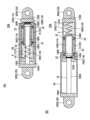
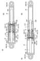
図2(A)、(B)に示すように、ダンパ10Aは、シリンダ12と、中空ケース14と、ロッド16と、付勢部材18と、取り付け部材20と、粘性流体用通路24とを備え、シリンダ12と、中空ケース14と、ロッド16と、付勢部材18と、取り付け部材20とは金属製である。As shown in Figures 2(A) and (B), the
シリンダ12は、円筒状に延在するシリンダ本体1202と、シリンダ本体1202の軸心方向の両端を閉塞する一対の第1シリンダ端面壁1204および第2シリンダ端面壁1206とを備え、シリンダ12の内部はシリンダ室1210として形成されている。
シリンダ室1210には、粘性流体である作動油Vが収容されている。
作動油Vは、例えば、耐熱性、耐寒性、化学的安定性に優れ、非腐食性で他材料へ悪影響を与えることがなく無害な高粘度の粘性オイル(シリコンオイル)である。 The
The
The hydraulic oil V is, for example, a highly viscous oil (silicon oil) that has excellent heat resistance, cold resistance, and chemical stability, is non-corrosive, does not adversely affect other materials, and is harmless.
中空ケース14は、シリンダ室1210でシリンダ12の軸心上に往復移動可能に配置され、シリンダ12の軸心方向においてシリンダ室1210を二分している。
中空ケース14は、その内部にシリンダ12の軸心方向に延在する内部空間Sを有している。
中空ケース14は、円筒状に延在するケース本体1402と、ケース本体1402の軸心方向の両端を閉塞する第1ケース端面壁1404および第2ケース端面壁1406とを備え、したがって、内部空間Sの延在方向の両端に第1、第2ケース端面壁1404、1406が位置している。
ケース本体1402の外周面には複数のスペーサ22が取り付けられており、複数のスペーサ22により中空ケース14の外周面とシリンダ12の内周面との間に環状の隙間13が形成されている。
本実施の形態では、複数のスペーサ22は、中空ケース14の外周面の中空ケース14の延在方向の両端寄りの箇所に周方向に等間隔をおいて設けられ、シリンダ本体1202の内周面に摺動可能に接触している。
したがって、中空ケース14は、複数のスペーサ22を介してシリンダ12の内周面でシリンダ12の軸心上に往復移動可能に支持されている。
なお、中空ケース14のシリンダ12の軸心方向への移動を円滑に行なうため、スペーサ22は、シリンダ12の内周面に対して円滑に摺動することが好ましく、スペーサ22を構成する材料として、摩擦係数が低い合成樹脂材料など従来公知の様々な材料が使用可能である。
また、本実施の形態では、スペーサ22を中空ケース14の外周面に設けた場合について説明したが、スペーサ22をシリンダ12の内周面に取り付けて、スペーサ22が中空ケース14の外周面と摺動するようにしてもよい。 The
The
The
A plurality of
In this embodiment,
Therefore, the
In order to smoothly move the
In addition, in this embodiment, the case where the
粘性流体用通路24は、中空ケース14により二分されたシリンダ室1210を連通し中空ケース14の移動時に粘性流体が通過することで粘性抵抗を生じさせるものである。
本実施の形態では、粘性流体用通路24は中空ケース14の外周部に設けられている。
詳細には、粘性流体用通路24は、中空ケース14の外周面とシリンダ12の内周面との間に形成された環状の隙間13のうち複数のスペーサ22を除く部分によって形成されている。
なお、シリンダ12の外部に、二分されたシリンダ室1210を連通する管体を設け、この管体により粘性流体用通路24を設けてもよいが、実施の形態のように、粘性流体用通路24をシリンダ12の内部に設けると、ダンパ10Aのコンパクト化を図る上で有利となる。 The
In this embodiment, the
In detail, the
It is also possible to provide a tube outside the
ロッド16は、シリンダ12の軸心上に配置されその長手方向の一端1602がシリンダ12の軸心方向の端部である第1シリンダ端面壁1204の中心から往復移動可能にかつ液密に突出している。
ロッド16は、ロッド16が突出する側の第1シリンダ端面壁1204から第1ケース端面壁1404を移動可能かつ液密に貫通してロッド16の他端1604が中空ケース14の内部に位置している。
ロッド16の他端1604に、中空ケース14の内部で第1、第2ケース端面壁1404、1406に当接可能な当接部1606が設けられている。 The
The
The
付勢部材18は、当接部1606がシリンダ12の軸心方向の中央に位置した状態で、中空ケース14の延在方向の中央をシリンダ12の軸心方向の中央に位置させるものである。
付勢部材18は、中空ケース14の外部かつシリンダ室1210内で、第1シリンダ端面壁1204と第1ケース端面壁1404との間でロッド16に巻装されて配置された第1コイルスプリング1802と、第2シリンダ端面壁1206と第2ケース端面壁1406との間に配置された第2コイルスプリング1804とで構成されている。 The biasing
The biasing
取り付け部材20は、シリンダ12の軸心方向の一方の端部から突出したロッド16の端部に設けられた第1取り付け部材2002と、シリンダ12の軸心方向の他方の端部に取り付けられた第2取り付け部材2004とを備えている。
図1に示すように、第1取り付け部材2002はシリンダ12の軸心方向と直交する鉛直方向に延在する軸21Aを介して軸21Aの周りに揺動可能な状態で、上部構造体4の下部に設けられた保持部材4Aに連結されている。
第2取り付け部材2004はシリンダ12の軸心方向と直交する鉛直方向に延在する軸21Bを介して軸21Bの周りに揺動可能な状態で、下部構造体2の上部に取り付けられた保持部材2Aに連結されている。
なお、図2(A)において符号2002A、2004Aは軸21A、21Bが挿通される軸受孔を示す。
また、符号26は、第1取り付け部材2002と一体に設けられ、第1取り付け部材2002からシリンダ12の軸心方向に沿って延在形成されシリンダ12の外周面を覆う円筒状の防塵用カバーを示す。 The mounting
As shown in FIG. 1, the first mounting
The
In FIG. 2A,
Furthermore, the
なお、本実施の形態では、第1取り付け部材2002が上部構造体4に連結され、第2取り付け部材2004が下部構造体2に連結されているが、反対にして配置されていてもよい。すなわち、第1取り付け部材2002が下部構造体2に連結され、第2取り付け部材2004が上部構造体4に連結されるように配置してもよい。In this embodiment, the first mounting
次に、ダンパ10Aの作用効果について説明する。
地震動が生じていない場合、下部構造体2に対して上部構造体4は初期位置(中立位置)に位置している。
図2(A)に示すように、上部構造体4の初期位置において、当接部1606はシリンダ12の軸心方向の中央に位置している。
そして、第1、第2コイルスプリング1802、1804の付勢力により、中空ケース14の延在方向の中央はシリンダ12の軸心方向の中央に位置されている。 Next, the function and effect of the
When no seismic motion is occurring, the
As shown in FIG. 2A , in the initial position of the
The biasing forces of the first and
ここで、地震動が生じた場合、上部構造体44と下部構造体22との間で水平方向に変位が生じる。すなわち、図1に示すようにX1方向およびX2方向に変位が生じる。
これに伴い、ロッド16がシリンダ12の軸心方向に移動して、当接部1606が中空ケース14の内部空間Sを中空ケース14の軸心方向に往復移動する。
発生頻度、確率が比較的高いと考えられる通常の設計で想定する地震動が生じた場合、すなわち、地震動が小さい場合、当接部1606が第1ケース端面壁1404と第2ケース端面壁1406の間で往復移動するものの、当接部1606が第1、第2ケース端面壁1404、1406を押圧しない状態では、中空ケース14はシリンダ12の軸心方向に移動せず、したがって、ロッド16に対して抵抗力が作用しないため、ダンパ10Aによる減衰力は発揮されない。
このように、通常の設計で想定する地震動が生じた場合には、ダンパ10Aの減衰力が発揮されないため、積層ゴム6による免震性能を低下させることがない。 When an earthquake motion occurs, a horizontal displacement occurs between the upper structure 44 and the
Accordingly, the
When earthquake motion occurs as assumed in normal designs, which is considered to have a relatively high frequency and probability of occurrence, i.e., when the earthquake motion is small, the
In this way, when earthquake motion assumed in normal design occurs, the damping force of the
一方、発生頻度、確率が比較的低いと考えられる設計での想定を超える地震動が生じた場合、すなわち、地震動が大きい場合、当接部1606が第1ケース端面壁1404あるいは第2ケース端面壁1406を押圧する状態では、ロッド16から当接部1606を介して入力する荷重によって中空ケース14はシリンダ12の軸心方向に往復移動される。
すなわち、図3(A)に示すようにロッド16がシリンダ12内部に没入しダンパ10Aが短縮された状態と、図3(B)に示すようにロッド16がシリンダ12内部から突出しダンパ10Aが伸長された状態との間でダンパ10Aが伸縮される。
この状態では、図3(A)に示すように、第2シリンダ端面壁1206と第2ケース端面壁1406との間のシリンダ室1210の作動油Vが粘性流体用通路24を通過して第1シリンダ端面壁1204と第1ケース端面壁1404との間のシリンダ室1210へ流れ、あるいは、図3(B)に示すように、第1シリンダ端面壁1204と第1ケース端面壁1404との間のシリンダ室1210の作動油Vが粘性流体用通路24を通過して第2シリンダ端面壁1206と第2ケース端面壁1406との間のシリンダ室1210へ流れる。
このように、シリンダ室1210の作動油Vが粘性流体用通路24を通過して流れることにより粘性抵抗が生じるため、ロッド16に対してこの粘性抵抗が作用することでダンパ10Aによる減衰力が発揮される。
このように、設計での想定を超える地震動が生じた場合には、その地震動に応じた減衰力を発揮させることができる。 On the other hand, if seismic motion occurs that exceeds the assumptions made in the design, which is considered to have a relatively low frequency and probability of occurrence, i.e., if the seismic motion is large, when the
That is, the
In this state, as shown in FIG. 3(A), the hydraulic oil V in the
In this way, viscous resistance is generated as the hydraulic oil V in the
In this way, if earthquake motion occurs that exceeds the design assumptions, a damping force corresponding to that earthquake motion can be exerted.
また、地震動が収束すると、上部構造体4は下部構造体2に対して初期位置(中立位置)に戻るため、図2(A)に示すように、当接部1606はシリンダ12の軸心方向の中央に位置し、第1、第2コイルスプリング1802、1804の付勢力により、中空ケース14の延在方向の中央はシリンダ12の軸心方向の中央に位置された状態に復帰する。
このように、本実施の形態のダンパ10Aによれば、当接部1606がシリンダ12の軸心方向に移動する位置により、地震動の大きさに応じて減衰力の発揮の有無が切り換えられる。 Furthermore, when the seismic motion subsides, the
In this manner, according to the
このように、本実施の形態によれば、粘性流体が収容されたシリンダ室1210を有するシリンダ12と、シリンダ室1210でシリンダ12の軸心上に往復移動可能に配置されてシリンダ室1210を二分しシリンダ12の軸心方向に延在する内部空間Sを有する中空ケース14と、シリンダ12の軸心上でシリンダ室1210に配置されその長手方向の一端1602がシリンダ12の軸心方向の端部(シリンダ端面壁1204)から往復移動可能に突出するロッド16と、二分されたシリンダ室1210を連通する粘性流体用通路24とを備え、ロッド16に、中空ケース14の内部で一対のケース端面壁1404、1406に当接可能な当接部1606を設け、当接部1606がシリンダ12の軸心方向の中央に位置した状態で、中空ケース14の延在方向の中央をシリンダ12の軸心方向の中央に位置させる付勢部材18を設けた。
したがって、当接部1606が中空ケース14のケース端面壁1404、1406に当接するまではダンパ10Aの減衰力が発揮されず、当接部1606が中空ケース14のケース端面壁1404、1406に当接して中空ケース14をシリンダ12内で移動させることでダンパ10Aの減衰力が発揮される。
そのため、当接部1606がシリンダ12の軸心方向に移動する位置により、地震動の大きさに応じてダンパ10Aで発揮する減衰力の有無を切り替えることができ、簡易な構成により、通常の設計で想定する地震動に対する免震性能の低下を抑制すると共に、設計での想定を超える地震動に応じた減衰力を発揮させる上で有利となる。 Thus, according to this embodiment, the system includes a
Therefore, the damping force of
Therefore, depending on the position to which the
また、本実施の形態では、付勢部材18が、中空ケース14の外部かつシリンダ室1210内で、第1シリンダ端面壁1204と第1ケース端面壁1404との間に配置された第1コイルスプリング1802と、第2シリンダ端面壁1206と第2ケース端面壁1406との間に配置された第2コイルスプリング1804とで構成されているので、それら第1、第2コイルスプリング1802、1804を簡単に組み付けることができ、ダンパ10Aの構成の簡素化を図る上で有利となる。In addition, in this embodiment, the biasing
また、本実施の形態では、粘性流体用通路24は、中空ケース14の外周面とシリンダ12の内周面との間に形成されているので、粘性流体用通路24を簡単に形成でき、ダンパ10Aの構成の簡素化を図る上で有利となる。In addition, in this embodiment, the
また、本実施の形態では、シリンダ12の軸心方向の一方の端部から突出したロッド16の端部1602と、シリンダ12の軸心方向の他方の端部にそれぞれ取り付け部材2002、2004を取り付け、それら取り付け部材20のうちの一方の取り付け部材2004は下部構造体2に連結されると共に、他方の取り付け部材2002は上部構造体4に連結されているので、免震建物に対してダンパ10Aを簡単に設置する上で有利となる。In addition, in this embodiment, mounting
また、本実施の形態では、取り付け部材20は、シリンダ12の軸心方向と直交する鉛直方向に延在する軸21B、21Aの周りに揺動可能な状態で下部構造体2と上部構造体4に連結されているので、地震動により上部構造体4が下部構造体2に対して水平でシリンダ12の軸心方向と交差する方向に移動した場合でも、ダンパ10Aが揺動できるため、ダンパ10Aの破損を回避しつつダンパ10を機能させることができる。In addition, in this embodiment, the mounting
(第2の実施の形態)
次に図4を参照して第2の実施の形態に係るダンパ10Bについて説明する。
なお、以下の実施の形態においては、第1の実施の形態と同様の部分、部材については同一の符号を付してその説明を簡略化し、第1の実施の形態と異なる部分について重点的に説明する。
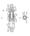
第2の実施の形態は、第1の実施の形態の変形例であり、粘性流体用通路24を中空ケース14に形成した点が第1の実施の形態と異なっている。
図4(A)、(B)に示すように、第1の実施の形態で設けられていたスペーサ22を省略し、中空ケース14の外周面がシリンダ12の内周面により摺動可能に支持されている。
粘性流体用通路24は、ケース本体1402の周方向に等間隔をおいてケース本体1402の軸心方向に貫通して設けられた貫通孔28により構成されている。
したがって、設計での想定を超える地震動が生じた場合には、第1の実施の形態の場合と同様に、ダンパ10Bが伸縮し中空ケース14がシリンダ12内部で往復移動することにより、シリンダ室1210の作動油Vが粘性流体用通路24を通過して流れることにより粘性抵抗が生じるため、ロッド16に対してこの粘性抵抗が作用することでダンパ10Bによる減衰力が発揮される。
このような第2の実施の形態によっても第1の実施の形態と同様の効果が奏される。
また、第2の実施の形態によれば、ケース本体1402に設ける粘性流体用通路24(貫通孔28)の数や内径の寸法を変更することによって、作動油Vが粘性流体用通路24を通過して流れる際の粘性抵抗を増減でき、ダンパ10Bによる減衰力を容易に設定する上で有利となる。Second Embodiment
Next, a
In the following embodiments, the same parts and members as those in the first embodiment are denoted by the same reference numerals, and the description thereof will be simplified, and the description will focus on the parts that are different from the first embodiment.
The second embodiment is a modification of the first embodiment, and differs from the first embodiment in that the
As shown in FIGS. 4A and 4B, the
The
Therefore, in the event of seismic motion that exceeds the design assumptions, as in the first embodiment, the
The second embodiment as described above also provides the same effects as the first embodiment.
Furthermore, according to the second embodiment, by changing the number and inner diameter dimensions of the viscous fluid passages 24 (through holes 28) provided in the
(第3の実施の形態)
次に、図5、図6を参照して第3の実施の形態に係るダンパ10Cについて説明する。
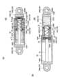
第1の実施の形態では、付勢部材18がシリンダ室1210内でかつ中空ケース14の外部に配置されていたが、第3の実施の形態では、付勢部材18が中空ケース14の内部に配置されている点が第1の実施の形態と異なっている。
図5(A)に示すように、付勢部材18は、第1の実施の形態と同様に、当接部1606がシリンダ12の軸心方向の中央に位置した状態で、中空ケース14の延在方向の中央をシリンダ12の軸心方向の中央に位置させるものである。
第3の実施の形態では、付勢部材18は、中空ケース14の内部で、第1ケース端面壁1404と当接部1606との間に配置された第1コイルスプリング1810と、第2ケース端面壁1406と当接部1606との間に配置された第2コイルスプリング1812とで構成されている。Third Embodiment
Next, a
In the first embodiment, the biasing
As shown in FIG. 5A, similarly to the first embodiment, the urging
In the third embodiment, the biasing
図1を流用して説明すると、第1の実施の形態と同様に、ダンパ10Cを下部構造体2としての基礎と上部構造体4としての建物との鉛直方向の間に設置されているものとする。Referring to Figure 1, as in the first embodiment, the
次にダンパ10Cの作用効果について説明する。
地震動が生じていない場合、下部構造体2に対して上部構造体4は初期位置に位置している。
図5(A)に示すように、上部構造体4の初期位置において、当接部1606はシリンダ12の軸心方向の中央に位置している。
そして、第1、第2コイルスプリング1810、1812の付勢力により、中空ケース14の延在方向の中央はシリンダ12の軸心方向の中央に位置されている。 Next, the function and effect of the
When no seismic motion is occurring, the
As shown in FIG. 5A , in the initial position of the
The biasing forces of the first and
ここで、地震動が生じた場合、上部構造体4と下部構造体2との間で水平方向に変位が生じる。これに伴い、ロッド16がシリンダ12の軸心方向に移動して、当接部1606が中空ケース14の内部空間Sを中空ケース14の軸心方向に往復移動する。
発生頻度、確率が比較的高いと考えられる通常の設計で想定する地震動が生じた場合、すなわち、地震動が小さい場合、当接部1606が第1ケース端面壁1404と第2ケース端面壁1406の間で往復移動する。
当接部1606と第1ケース端面壁1404との間で第1コイルスプリング1810が圧縮されるものの、第1コイルスプリング1810が余裕をもってたわむことができる状態では、また、当接部1606と第2ケース端面壁1406との間で第2コイルスプリング1812が圧縮されるものの、第2コイルスプリング1812が余裕をもってたわむことができる状態では、当接部1606から第1、第2コイルスプリング1810、1812を介して第1、第2ケース端面壁1404、1406を押圧する荷重は小さく、中空ケース14はシリンダ12の軸心方向に僅かに移動するに過ぎず、したがって、ロッド16に対して抵抗力がほとんど作用しないため、ダンパ10Cによる減衰力はほとんど発揮されない。
このように、通常の設計で想定する地震動が生じた場合には、ダンパ10Cの減衰力がほとんど発揮されないため、積層ゴム6による免震性能を低下させることがない。 Here, when seismic motion occurs, horizontal displacement occurs between the
When earthquake motion occurs that is assumed in normal designs and is considered to have a relatively high occurrence frequency and probability, that is, when the earthquake motion is small, the
In a state in which the
In this way, when earthquake motion assumed in normal design occurs, the
一方、発生頻度、確率が比較的低いと考えられる設計での想定を超える地震動が生じた場合、すなわち、地震動が大きい場合、図6(A)に示すように、当接部1606と第2ケース端面壁1406との間で第2コイルスプリング1812がそれ以上たわむことができないほど圧縮された状態では、あるいは、図6(B)に示すように、当接部1606と第1ケース端面壁1404との間で第1コイルスプリング1810がそれ以上たわむことができないほど圧縮された状態では、当接部1606から第1、第2コイルスプリング1810、1812を介して第1、第2ケース端面壁1404、1406に荷重が入力する。
そのため、当接部1606が第1ケース端面壁1404あるいは第2ケース端面壁1406を押圧し、中空ケース14はシリンダ12の軸心方向に往復移動される。
すなわち、図6(A)に示すようにロッド16がシリンダ12内部に没入しダンパ10Cが短縮された状態と、図6(B)に示すようにロッド16がシリンダ12内部から突出しダンパ10Cが伸長された状態との間でダンパ10Cが伸縮される。
この状態では、図6(A)に示すように第2シリンダ端面壁1206と第2ケース端面壁1406との間のシリンダ室1210の作動油Vが粘性流体用通路24を通過して第1シリンダ端面壁1204と第1ケース端面壁1404との間のシリンダ室1210へ流れ、あるいは、図6(B)に示すように第1シリンダ端面壁1204と第1ケース端面壁1404との間のシリンダ室1210の作動油Vが粘性流体用通路24を通過して第2シリンダ端面壁1206と第2ケース端面壁1406との間のシリンダ室1210へ流れる。
このように、シリンダ室1210の作動油Vが粘性流体用通路24を通過して流れることにより粘性抵抗が生じるため、ロッド16に対してこの粘性抵抗が作用することでダンパ10Cによる減衰力が発揮される。
このように、設計での想定を超える地震動が生じた場合には、その地震動に応じた減衰力を発揮させることができる。 On the other hand, if seismic motion occurs that exceeds the assumptions made in the design, which is considered to have a relatively low frequency and probability of occurrence, i.e., if the seismic motion is large, when the
As a result, the
That is, the
In this state, as shown in FIG. 6 (A), the hydraulic oil V in the
In this way, viscous resistance is generated as the hydraulic oil V in the
In this way, if earthquake motion occurs that exceeds the design assumptions, a damping force corresponding to that earthquake motion can be exerted.
また、地震動が収束すると、上部構造体4は下部構造体2に対して初期位置に戻るため、図5(A)に示すように、当接部1606はシリンダ12の軸心方向の中央に位置し、第1、第2コイルスプリング1810、1812の付勢力により、中空ケース14の延在方向の中央はシリンダ12の軸心方向の中央に位置された状態に復帰する。
このように、第3実施の形態のダンパ10Cによれば、当接部1606がシリンダ12の軸心方向に移動する位置により、地震動の大きさに応じて減衰力の発揮の有無が切り換えられる。 Furthermore, when the seismic motion subsides, the
In this way, according to the
このように、第3実施の形態によれば、第1、第2コイルスプリング1810、1812が圧縮変形している間は、ダンパ10Cの減衰力が発揮されず、第1、第2コイルスプリング1810、1812が圧縮変形できなくなると、中空ケース14をシリンダ12内で移動させることでダンパ10Cの減衰力が発揮される。
そのため、当接部1606がシリンダ12の軸心方向に移動する位置により、地震動の大きさに応じてダンパ10Cで発揮する減衰力の有無を切り替えることができ、簡易な構成により、通常の設計で想定する地震動に対する免震性能の低下を抑制すると共に、設計での想定を超える地震動に応じた減衰力を発揮させる上で有利となる。
また、第3の実施の形態では、付勢部材18を、中空ケース14の内部に配置された第1コイルスプリング1810と第2コイルスプリング1812とで構成したので、それら第1、第2コイルスプリング1810、1812が占有するシリンダ12の軸心方向のスペースのコンパクト化を図れ、ダンパ10Cの小型化を図る上で有利となる。 Thus, according to the third embodiment, while the first and
Therefore, depending on the position to which the
Furthermore, in the third embodiment, the biasing
(第4の実施の形態)
次に図7、図8を参照して第4の実施の形態に係るダンパ10Dについて説明する。
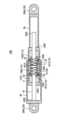
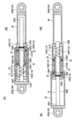
第4の実施の形態は、第3の実施の形態の変形例であり、第3の実施の形態では、ロッド16が第1シリンダ端面壁1204から突出していたのに対して、第4実施の形態では、ロッド16が第1シリンダ端面壁1204および第2シリンダ端面壁1206の双方から突出している点が第3の実施の形態と異なっている。(Fourth embodiment)
Next, a
The fourth embodiment is a modified example of the third embodiment, and differs from the third embodiment in that, whereas in the third embodiment, the
図7に示すように、ロッド16は、シリンダ12の軸心上に往復移動可能に配置され、内部空間Sの延在方向両端の第1、第2ケース端面壁1404、1406およびシリンダ12の軸心方向の両端の第1、第2シリンダ端面壁1204、1206を往復移動可能にかつ液密に貫通している。
すなわち、ロッド16の長手方向の一端1620が第1シリンダ端面壁1204から往復移動可能にかつ液密に突出し、ロッド16の長手方向の他端1622が第2シリンダ端面壁1206から往復移動可能にかつ液密に突出している。
中空ケース14の内部に位置するロッド16の箇所に、中空ケース14の内部で一対のケース端面壁1404、1406に当接可能な当接部1610が設けられている。
付勢部材18は、第3の実施の形態と同様に、中空ケース14の内部で、第1ケース端面壁1404と当接部1610との間でロッド16に巻装されて配置された第1コイルスプリング1810と、第2ケース端面壁1406と当接部1610との間でロッド16に巻装されて配置された第2コイルスプリング1812とで構成されている。
また、シリンダ12の第2シリンダ端面壁1206からシリンダ12の軸心方向に沿ってロッド16を覆う長さと内径で形成された円筒状の防塵用カバー30が設けられている。
第2取り付け部材2004は、防塵用カバー30の先端に設けられている。 As shown in Figure 7, the
That is, one
At a portion of the
As in the third embodiment, the biasing
In addition, a
The
第4の実施の形態においても、通常の設計で想定する地震動が生じた場合、すなわち、地震動が小さい場合、当接部1610から第1、第2コイルスプリング1810、1812を介して第1、第2ケース端面壁1404、1406を押圧する荷重は小さく、中空ケース14はシリンダ12の軸心方向に僅かに移動するに過ぎず、したがって、ロッド16に対して抵抗力がほとんど作用しないため、ダンパ10Dによる減衰力はほとんど発揮されない。
このように、通常の設計で想定する地震動が生じた場合には、ダンパ10Dの減衰力がほとんど発揮されないため、積層ゴム6による免震性能を低下させることがない。 Even in the fourth embodiment, when an earthquake motion anticipated in a normal design occurs, i.e., when the earthquake motion is small, the load pressing against the first and second case end
In this way, when earthquake motion assumed in normal design occurs, the
一方、発生頻度、確率が比較的低いと考えられる設計での想定を超える地震動が生じた場合、すなわち、地震動が大きい場合、図8(A)に示すように、当接部1606と第2ケース端面壁1406との間第2コイルスプリング1812がそれ以上たわむことができないほど圧縮された状態では、また、図8(B)に示すように、当接部1606と第1ケース端面壁1404との間で第1コイルスプリング1810がそれ以上たわむことができないほど圧縮された状態では、当接部1610から第1、第2コイルスプリング1810、1812を介して第1、第2ケース端面壁1404、1406に荷重が入力する。
そのため、当接部1606が第1ケース端面壁1404あるいは第2ケース端面壁1406を押圧し、中空ケース14はシリンダ12の軸心方向に往復移動される。
すなわち、図8(A)に示すようにロッド16がシリンダ12内部に没入しダンパ10Dが短縮された状態と、図8(B)に示すようにロッド16がシリンダ12内部から突出しダンパ10Dが伸長された状態との間でダンパ10Dが伸縮される。
この状態では、図8(A)に示すように第2シリンダ端面壁1206と第2ケース端面壁1406との間のシリンダ室1210の作動油Vが粘性流体用通路24を通過して第1シリンダ端面壁1204と第1ケース端面壁1404との間へ流れ、あるいは、図8(B)に示すように第1シリンダ端面壁1204と第1ケース端面壁1404との間のシリンダ室1210の作動油Vが粘性流体用通路24を通過して第2シリンダ端面壁1206と第2ケース端面壁1406との間へ流れる。
このように、シリンダ室1210の作動油Vが粘性流体用通路24を通過して流れることにより粘性抵抗が生じるため、ロッド16に対してこの粘性抵抗が作用することでダンパ10Dによる減衰力が発揮される。
このように、設計での想定を超える地震動が生じた場合には、その地震動に応じた減衰力を発揮させることができる。
すなわち、当接部1610がシリンダ12の軸心方向に移動する位置により、地震動の大きさに応じて減衰力の発揮の有無が切り換えられ、第3の実施の形態と同様の効果が奏される。 On the other hand, if seismic motion occurs that exceeds the assumptions made in the design, which is considered to have a relatively low frequency and probability of occurrence, i.e., if the seismic motion is large, when the
As a result, the
That is, the
In this state, as shown in Figure 8 (A), the hydraulic oil V in the
In this way, viscous resistance is generated as the hydraulic oil V in the
In this way, if earthquake motion occurs that exceeds the design assumptions, a damping force corresponding to that earthquake motion can be exerted.
In other words, depending on the position to which the
また、地震動が収束すると、上部構造体4は下部構造体2に対して初期位置に戻るため、図7に示すように、当接部1606はシリンダ12の軸心方向の中央に位置し、第1、第2コイルスプリング1810、1812の付勢力により、中空ケース14の延在方向の中央はシリンダ12の軸心方向の中央に位置された状態に復帰する。
このように、第4実施の形態のダンパ10Dによれば、当接部1606がシリンダ12の軸心方向に移動する位置により、地震動の大きさに応じて減衰力の発揮の有無が切り換えられる。 In addition, when the seismic motion subsides, the
In this way, according to the
第4の実施の形態によれば、粘性流体が収容されたシリンダ室1210を有するシリンダ12と、シリンダ室1210でシリンダ12の軸心上に往復移動可能に配置されてシリンダ室1210を二分しシリンダ12の軸心方向に延在する内部空間Sを有する中空ケース14と、シリンダ12の軸心上でシリンダ室1210に配置され、内部空間Sの延在方向の両端の中空ケース14の一対のケース端面壁1404、1406およびシリンダ12の軸心方向の両端を往復移動可能に貫通するロッド16と、二分されたシリンダ室1210を連通する粘性流体用通路24とを備え、ロッド16に、中空ケース14の内部で一対のケース端面壁1404、1406に当接可能な当接部1610を設け、当接部1610がシリンダ12の軸心方向の中央に位置した状態で、中空ケース14の延在方向の中央をシリンダ12の軸心方向の中央に位置させる付勢部材18を設けた。
したがって、第1、第2コイルスプリング1810、1812が圧縮変形している間は、ダンパ10Dの減衰力が発揮されず、第1、第2コイルスプリング1810、1812が圧縮変形できなくなると、中空ケース14をシリンダ12内で移動させることでダンパ10Dの減衰力が発揮される。
そのため、当接部1610がシリンダ12の軸心方向に移動する位置により、地震動の大きさに応じてダンパ10Dで発揮する減衰力の有無を切り替えることができ、簡易な構成により、通常の設計で想定する地震動に対する免震性能の低下を抑制すると共に、設計での想定を超える地震動に応じた減衰力を発揮させる上で有利となる。 According to the fourth embodiment, there is provided a
Therefore, while the first and
Therefore, depending on the position to which the
ここで第4の実施の形態と第3の実施の形態とを比較して説明する。
第4の実施の形態において、図7に示すように、第1シリンダ端面壁1204と第1ケース端面壁1404との間に挟まれた第1シリンダ室に収容されている作動油Vの体積を体積V1とし、第2シリンダ端面壁1206と第2ケース端面壁1406との間に挟まれた第2シリンダ室に収容されている作動油Vの体積を体積V2とする。
この場合、体積V1は第1シリンダ室の体積から第1シリンダ室に位置するロッド16の体積を除いたものとなり、体積V2は第2シリンダ室の体積から第2シリンダ室に位置するロッド16の体積を除いたものとなる。
したがって、第4の実施の形態では、図8(A)、(B)に示すように、地震動によりダンパ10Dが伸縮して中空ケース14がシリンダ12の軸心方向に往復移動し、作動油Vが第1シリンダ室から粘性流体用通路24を通って第2シリンダ室に流通する場合と、逆に作動油Vが第2シリンダ室から粘性流体用通路24を通って第1シリンダ室に流通する場合とで作動油Vの流通量は同一となる。
そのため、第4の実施の形態では、ダンパ10Dの伸長時と縮小時とで発揮される減衰量は同じものとなる。 Here, the fourth embodiment will be compared with the third embodiment.
In the fourth embodiment, as shown in FIG. 7 , the volume of the hydraulic oil V contained in the first cylinder chamber sandwiched between the first
In this case, volume V1 is the volume of the first cylinder chamber minus the volume of the
Therefore, in the fourth embodiment, as shown in Figures 8 (A) and (B), seismic motion causes the
Therefore, in the fourth embodiment, the amount of damping exerted when the
これに対して、図5に示す第3の実施の形態のように、ロッド16が中空ケース14の第1ケース端面壁1404およびシリンダ12の第1シリンダ端面壁1204のみを移動可能に貫通している場合は、第1シリンダ端面壁1204と第1ケース端面壁1404との間に挟まれた第1シリンダ室に収容されている作動油Vの体積V1はロッド16の体積分だけ小さなものとなる一方、第2シリンダ端面壁1206と第2ケース端面壁1406との間に挟まれた第2シリンダ室に収容されている作動油Vの体積V2はロッド16の体積の影響を受けない。
したがって、地震動によりダンパ10Cが伸縮して中空ケース14がシリンダ12の軸心方向に往復移動し、作動油Vが第1シリンダ室から粘性流体用通路24を通って第2シリンダ室に流通する場合と、逆に作動油Vが第2シリンダ室から粘性流体用通路24を通って第1シリンダ室に流通する場合とで作動油Vの流通量には違いが生じる。
そのため、第3の実施の形態では、ダンパ10Cの伸長時と縮小時とで発揮される減衰量に差異が生じることとなる。
したがって、第4の実施の形態によれば、上述のようにダンパ10Dの伸長時と縮小時とで発揮される減衰量に差異が生じないため、第3の実施の形態に比較して、ダンパ10Dの性能を向上させる上でより有利となる。
一方、第3の実施の形態では、シリンダ12の一方のシリンダ端面壁1204からロッド16が突出し、他方のシリンダ端面壁1206からはロッド16が突出しないので、ダンパ10Cの全長を第4の実施の形態に比較して短縮することができるため、限られたスペースにダンパ10Dを設置する上で有利となる。 In contrast, when the
Therefore, when seismic motion causes the
Therefore, in the third embodiment, a difference occurs in the amount of damping exerted when the
Therefore, according to the fourth embodiment, as described above, there is no difference in the amount of damping exerted when the
On the other hand, in the third embodiment, the
(第5の実施の形態)
次に図9、図10を参照して第5の実施の形態に係るダンパ10Eについて説明する。
第5の実施の形態は、第4の実施の形態の変形例であり、付勢部材18がシリンダ室1210内でかつ中空ケース14の外部に配置されている点が第4の実施の形態と異なっている。
すなわち、付勢部材18は、中空ケース14の外部かつシリンダ室1210内で、第1シリンダ端面壁1204と第1ケース端面壁1404との間でロッド16に巻装されて配置された第1コイルスプリング1802と、第2シリンダ端面壁1206と第2ケース端面壁1406との間でロッド16に巻装されて配置された第2コイルスプリング1804とで構成されている。
図9は、地震動が生じていない上部構造体4の初期位置において、当接部1606はシリンダ12の軸心方向の中央に位置している。
そして、第1、第2コイルスプリング1802、1804の付勢力により、中空ケース14の延在方向の中央はシリンダ12の軸心方向の中央に位置されている。
ここで、地震動が生じた場合、上部構造体4と下部構造体2との間で水平方向に変位が生じる。これに伴い、ロッド16がシリンダ12の軸心方向に移動して、当接部1606が中空ケース14の内部空間Sを中空ケース14の軸心方向に往復移動する。
発生頻度、確率が比較的高いと考えられる通常の設計で想定する地震動が生じた場合、すなわち、地震動が小さい場合、当接部1606が第1ケース端面壁1404と第2ケース端面壁1406の間で往復移動し、第1コイルスプリング1802と第2コイルスプリング1804は圧縮されず、したがって、中空ケース14はシリンダ12の軸心方向に移動せず、ダンパ10Eの減衰力が発揮されず、積層ゴム6による免震性能を低下させることがない。Fifth embodiment
Next, a
The fifth embodiment is a modification of the fourth embodiment, and differs from the fourth embodiment in that the biasing
That is, the biasing
In Figure 9, in the initial position of the
The biasing forces of the first and
Here, when seismic motion occurs, horizontal displacement occurs between the
When earthquake motion occurs as assumed in normal designs, which is considered to have a relatively high frequency and probability of occurrence, i.e., when the earthquake motion is small, the
一方、発生頻度、確率が比較的低いと考えられる設計での想定を超える地震動が生じた場合、すなわち、地震動が大きい場合、当接部1606が第1ケース端面壁1404あるいは第2ケース端面壁1406を押圧する状態では、図10(A)、(B)に示すように、第1コイルスプリング1802あるいは第2コイルスプリング1804を圧縮しつつロッド16から当接部1606を介して入力する荷重によって中空ケース14はシリンダ12の軸心方向に往復移動される。
この状態では、図10(A)に示すように、第2シリンダ端面壁1206と第2ケース端面壁1406との間のシリンダ室1210の作動油Vが粘性流体用通路24を通過して第1シリンダ端面壁1204と第1ケース端面壁1404との間のシリンダ室1210へ流れ、あるいは、図10(B)に示すように、第1シリンダ端面壁1204と第1ケース端面壁1404との間のシリンダ室1210の作動油Vが粘性流体用通路24を通過して第2シリンダ端面壁1206と第2ケース端面壁1406との間のシリンダ室1210へ流れる。
このように、シリンダ室1210の作動油Vが粘性流体用通路24を通過して流れることにより粘性抵抗が生じるため、ロッド16に対してこの粘性抵抗が作用することでダンパ10Eによる減衰力が発揮される。
このように、設計での想定を超える地震動が生じた場合には、その地震動に応じた減衰力を発揮させることができる。 On the other hand, if seismic motion occurs that exceeds the assumptions made in the design, which is considered to have a relatively low frequency and probability of occurrence, i.e., if the seismic motion is large, when the
In this state, as shown in FIG. 10 (A), the hydraulic oil V in the
In this way, viscous resistance is generated as the hydraulic oil V in the
In this way, if earthquake motion occurs that exceeds the design assumptions, a damping force corresponding to that earthquake motion can be exerted.
また、地震動が収束すると、上部構造体4は下部構造体2に対して初期位置に戻るため、図9に示すように、当接部1606はシリンダ12の軸心方向の中央に位置し、第1、第2コイルスプリング1802、1804の付勢力により、中空ケース14の延在方向の中央はシリンダ12の軸心方向の中央に位置された状態に復帰する。
このように、第5の実施の形態においても、当接部1606がシリンダ12の軸心方向に移動する位置により、地震動の大きさに応じて減衰力の発揮の有無が切り換えられ、第4の実施の形態と同様の効果が奏される。 In addition, when the seismic motion subsides, the
In this way, in the fifth embodiment as well, the position to which the
2 下部構造体(基礎)
4 上部構造体(建物)
6 積層ゴム
10A-10E ダンパ
12 シリンダ
1202 シリンダ本体
1204 第1シリンダ端面壁
1206 第2シリンダ端面壁
1210 シリンダ室
13 環状の隙間
14 中空ケース
1402 ケース本体
1404 第1ケース端面壁
1406 第2ケース端面壁
16 ロッド
1602 一端
1604 他端
1606 当接部
1610 当接部
1620 一端
1622 他端
18 付勢部材
1802 第1コイルスプリング
1804 第2コイルスプリング
1810 第1コイルスプリング
1812 第2コイルスプリング
20 取り付け部材
2002 第1取り付け部材
2004 第2取り付け部材
21A 軸
21B 軸
22 スペーサ
24 粘性流体用通路
26 防塵用カバー
28 貫通孔
30 防塵用カバー
S 内部空間
V 作動油(粘性流体)2. Substructure (foundation)
4. Superstructure (building)
6 laminated
Claims (8)
Translated fromJapanese粘性流体が収容されたシリンダ室を有するシリンダと、
前記シリンダ室で前記シリンダの軸心上に往復移動可能に配置されて前記シリンダ室を二分し前記シリンダの軸心方向に延在する内部空間を有する中空ケースと、
前記シリンダの軸心上で前記シリンダ室に配置されその長手方向の一端が前記シリンダの軸心方向の端部から往復移動可能に突出するロッドと、
前記二分されたシリンダ室を連通し前記中空ケースの移動時に前記粘性流体が通過することで粘性抵抗を生じさせる粘性流体用通路とを備え、
前記ロッドは、前記内部空間の延在方向の両端の前記中空ケースの一対のケース端面壁のうち前記シリンダの端部から前記ロッドが突出する側の前記ケース端面壁を移動可能に貫通して前記ロッドの他端が前記中空ケースの内部に位置し、
前記ロッドの他端に、前記中空ケースの内部で前記一対のケース端面壁に当接可能な当接部が設けられ、
前記当接部が前記シリンダの軸心方向の中央に位置した状態で、前記中空ケースの延在方向の中央を前記シリンダの軸心方向の中央に位置させる付勢部材が設けられている、
ことを特徴とする免震建物用のダンパ。A damper for a seismically isolated building, comprising:
a cylinder having a cylinder chamber containing a viscous fluid;
a hollow case that is arranged in the cylinder chamber so as to be capable of reciprocating along an axis of the cylinder, divides the cylinder chamber into two, and has an internal space that extends in the axial direction of the cylinder;
a rod disposed in the cylinder chamber on the axis of the cylinder, one end of the rod in the longitudinal direction protruding reciprocally from an end of the cylinder in the axial direction;
a viscous fluid passage that connects the two divided cylinder chambers and through which the viscous fluid passes when the hollow case moves, generating viscous resistance;
the rod movably passes through one of a pair of case end walls of the hollow case at both ends in the extending direction of the internal space, the case end wall being on a side where the rod protrudes from the end of the cylinder, and the other end of the rod is positioned inside the hollow case;
a contact portion capable of contacting the pair of case end walls inside the hollow case is provided at the other end of the rod;
a biasing member is provided for positioning the center of the hollow case in the axial direction of the cylinder when the abutment portion is positioned in the center of the axial direction of the cylinder;
A damperfor a seismically isolated building .
前記シリンダ室で前記シリンダの軸心上に往復移動可能に配置されて前記シリンダ室を二分し前記シリンダの軸心方向に延在する内部空間を有する中空ケースと、
前記シリンダの軸心上で前記シリンダ室に配置され、前記内部空間の延在方向の両端の前記中空ケースの一対のケース端面壁および前記シリンダの軸心方向の両端を往復移動可能に貫通するロッドと、
前記二分されたシリンダ室を連通し前記中空ケースの移動時に前記粘性流体が通過することで粘性抵抗を生じさせる粘性流体用通路とを備え、
前記中空ケースの内部に位置するロッドの箇所に、前記中空ケースの内部で前記一対のケース端面壁に当接可能な当接部が設けられ、
前記当接部が前記シリンダの軸心方向の中央に位置した状態で、前記中空ケースの延在方向の中央を前記シリンダの軸心方向の中央に位置させる付勢部材が設けられている、
ことを特徴とするダンパ。 a cylinder having a cylinder chamber containing a viscous fluid;
a hollow case that is arranged in the cylinder chamber so as to be capable of reciprocating along an axis of the cylinder, divides the cylinder chamber into two, and has an internal space that extends in the axial direction of the cylinder;
a rod that is disposed in the cylinder chamber on the axis of the cylinder and that passes through a pair of case end walls of the hollow case at both ends in the extending direction of the internal space and both ends in the axial direction of the cylinder so as to be capable of reciprocating motion;
a viscous fluid passage that connects the two divided cylinder chambers and through which the viscous fluid passes when the hollow case moves, generating viscous resistance;
a contact portion capable of contacting the pair of case end walls inside the hollow case is provided at a portion of the rod located inside the hollow case;
a biasing member is provided for positioning the center of the hollow case in the axial direction of the cylinder when the abutment portion is positioned in the center of the axial direction of the cylinder;
A damper comprising:
ことを特徴とする請求項1または請求項2記載のダンパ。 The biasing member is composed of a first coil spring disposed inside the hollow case between one of the pair of case end walls and the abutment portion, and a second coil spring disposed between the other of the pair of case end walls and the abutment portion.
3. The damper according to claim 1 or 2.
前記付勢部材は、前記中空ケースの外部かつ前記シリンダ室内で、前記一対のシリンダ端面壁の一方と前記一対のケース端面壁の一方との間に配置された第1コイルスプリングと、前記一対のシリンダ端面壁の他方と前記一対のケース端面壁の他方との間に配置された第2コイルスプリングとで構成されている、
ことを特徴とする請求項1または請求項2記載のダンパ。 The cylinder has a pair of cylinder end walls located at both ends in the axial direction thereof,
The biasing member is composed of a first coil spring disposed outside the hollow case and within the cylinder chamber between one of the pair of cylinder end walls and one of the pair of case end walls, and a second coil spring disposed between the other of the pair of cylinder end walls and the other of the pair of case end walls.
3. The damper according to claim 1 or 2.
ことを特徴とする請求項1~4の何れか1項記載のダンパ。 The viscous fluid passage is formed between an outer peripheral surface of the hollow case and an inner peripheral surface of the cylinder.
The damper according to any one of claims 1 to 4.
前記粘性流体用通路は、前記ケース本体に、前記ケース本体の軸心方向に貫通して設けられている、
ことを特徴とする請求項1~4の何れか1項記載のダンパ。 the hollow case includes a case body that extends cylindrically and has both ends in an extending direction closed by the pair of case end walls,
The viscous fluid passage is provided in the case body so as to penetrate the case body in an axial direction of the case body.
The damper according to any one of claims 1 to 4.
前記シリンダの軸心方向の一方の端部から突出した前記ロッドの端部と、前記シリンダの軸心方向の他方の端部にそれぞれ取り付け部材が取り付けられ、
それら取り付け部材のうちの一方の前記取り付け部材は前記下部構造体に連結されると共に、他方の前記取り付け部材は前記上部構造体に連結されている、
ことを特徴とする請求項1~6の何れか1項記載のダンパ。 The damper is installed in a seismically isolated building that comprises an upper structure supported by a lower structure,
An attachment member is attached to an end of the rod protruding from one end of the cylinder in the axial direction and to the other end of the cylinder in the axial direction,
one of the mounting members is connected to the lower structure and the other mounting member is connected to the upper structure;
The damper according to any one of claims 1 to 6.
ことを特徴とする請求項7記載のダンパ。 The mounting member is connected to the lower structure and the upper structure in a state in which the mounting member can swing around an axis extending in a vertical direction perpendicular to the axial direction of the cylinder.
8. The damper according to claim 7.
Priority Applications (1)
| Application Number | Priority Date | Filing Date | Title |
|---|---|---|---|
| JP2021023540AJP7570250B2 (en) | 2021-02-17 | 2021-02-17 | Damper |
Applications Claiming Priority (1)
| Application Number | Priority Date | Filing Date | Title |
|---|---|---|---|
| JP2021023540AJP7570250B2 (en) | 2021-02-17 | 2021-02-17 | Damper |
Publications (2)
| Publication Number | Publication Date |
|---|---|
| JP2022125764A JP2022125764A (en) | 2022-08-29 |
| JP7570250B2true JP7570250B2 (en) | 2024-10-21 |
Family
ID=83058541
Family Applications (1)
| Application Number | Title | Priority Date | Filing Date |
|---|---|---|---|
| JP2021023540AActiveJP7570250B2 (en) | 2021-02-17 | 2021-02-17 | Damper |
Country Status (1)
| Country | Link |
|---|---|
| JP (1) | JP7570250B2 (en) |
Family Cites Families (5)
| Publication number | Priority date | Publication date | Assignee | Title |
|---|---|---|---|---|
| JPS5030795B1 (en)* | 1970-12-29 | 1975-10-03 | ||
| JPS5482888U (en)* | 1977-11-25 | 1979-06-12 | ||
| JPS6176001U (en)* | 1984-10-26 | 1986-05-22 | ||
| JPS61177234U (en)* | 1985-04-23 | 1986-11-05 | ||
| JPS63170626U (en)* | 1987-04-27 | 1988-11-07 |
- 2021
- 2021-02-17JPJP2021023540Apatent/JP7570250B2/enactiveActive
Also Published As
| Publication number | Publication date |
|---|---|
| JP2022125764A (en) | 2022-08-29 |
Similar Documents
| Publication | Publication Date | Title |
|---|---|---|
| US10655700B2 (en) | Force limiting device | |
| JP6217181B2 (en) | Floor seismic isolation system | |
| JP4852552B2 (en) | Negative rigid device and seismic isolation structure provided with the negative rigid device | |
| JP2014098439A (en) | Vibration suppression device | |
| JP6186272B2 (en) | Vibration suppression device | |
| JP7570250B2 (en) | Damper | |
| JP2811524B2 (en) | Viscous type vibration dampers acting in horizontal and vertical directions | |
| JP6894769B2 (en) | Seismic isolation damper | |
| JP2002130370A (en) | Seismic isolation device | |
| JP7268973B2 (en) | seismic isolation damper | |
| JP2018135904A (en) | Horizontal type damper | |
| JP2017032055A (en) | Cylinder device | |
| JP2011012785A (en) | Suspension device | |
| JP2011047421A (en) | Damping device | |
| JP7499087B2 (en) | Damper system and seismic isolation structure equipped with same | |
| JP2015010650A (en) | Oil damper, and damper system | |
| JP7609656B2 (en) | Viscous Damper | |
| US7182190B2 (en) | Vibration damper with fire safety device | |
| JP6720570B2 (en) | Damper | |
| JP6875961B2 (en) | Seismic isolation damper | |
| JP6971895B2 (en) | Coupling device | |
| JP7186388B2 (en) | seismic isolation damper | |
| JP6810579B2 (en) | Seismic isolation damper | |
| JP6280934B2 (en) | Torsion device | |
| JP4579760B2 (en) | Seismic isolation structure |
Legal Events
| Date | Code | Title | Description |
|---|---|---|---|
| A621 | Written request for application examination | Free format text:JAPANESE INTERMEDIATE CODE: A621 Effective date:20231016 | |
| A977 | Report on retrieval | Free format text:JAPANESE INTERMEDIATE CODE: A971007 Effective date:20240322 | |
| A131 | Notification of reasons for refusal | Free format text:JAPANESE INTERMEDIATE CODE: A131 Effective date:20240409 | |
| A131 | Notification of reasons for refusal | Free format text:JAPANESE INTERMEDIATE CODE: A131 Effective date:20240730 | |
| A521 | Request for written amendment filed | Free format text:JAPANESE INTERMEDIATE CODE: A523 Effective date:20240808 | |
| TRDD | Decision of grant or rejection written | ||
| A01 | Written decision to grant a patent or to grant a registration (utility model) | Free format text:JAPANESE INTERMEDIATE CODE: A01 Effective date:20241001 | |
| A61 | First payment of annual fees (during grant procedure) | Free format text:JAPANESE INTERMEDIATE CODE: A61 Effective date:20241008 | |
| R150 | Certificate of patent or registration of utility model | Ref document number:7570250 Country of ref document:JP Free format text:JAPANESE INTERMEDIATE CODE: R150 |