JP7569889B2 - Display device - Google Patents
Display deviceDownload PDFInfo
- Publication number
- JP7569889B2 JP7569889B2JP2023093806AJP2023093806AJP7569889B2JP 7569889 B2JP7569889 B2JP 7569889B2JP 2023093806 AJP2023093806 AJP 2023093806AJP 2023093806 AJP2023093806 AJP 2023093806AJP 7569889 B2JP7569889 B2JP 7569889B2
- Authority
- JP
- Japan
- Prior art keywords
- patient
- display
- information
- biometric information
- value
- Prior art date
- Legal status (The legal status is an assumption and is not a legal conclusion. Google has not performed a legal analysis and makes no representation as to the accuracy of the status listed.)
- Active
Links
Images


Landscapes
- Measuring And Recording Apparatus For Diagnosis (AREA)
- Medical Treatment And Welfare Office Work (AREA)
Description
Translated fromJapanese本発明は、表示装置に関する。The present invention relates to a display device.
従来、複数バイタルのトレンド表示装置で異常生体情報と判断された情報については、トレンド表示形態を変更する表示手段を有しており、関連する情報の表示形態の変更をする発明が知られている(例えば、特許文献1参照)。Conventionally, when a trend display device for multiple vital signs determines that the information is abnormal biological information, it has a display means for changing the trend display format, and there is an invention known that changes the display format of related information (see, for example, Patent Document 1).
上述した特許文献1では、グラフは表示されるものの、単にグラフが表示されているだけであり、例えば患者状態が異常状態であるのか、正常状態であるのかを把握するにはグラフをそれぞれ確認する必要があり、容易に把握することはできなかった。In the above-mentioned
また、上述した特許文献1では、STレベルトレンドの表示の解決手段を抽象化した発明であり、例えば複数の生体情報の値の閾値が同じ単位系(Y軸)で表現されている。しかし、異なる単位系の生体情報表示を考えた場合、同一のトレンド表示の中に複数の閾値表示をするといったことは出来なかった。In addition, the above-mentioned
本開示された発明の目的は、以下明細書に記載された課題を解決する表示装置を提供することである。The object of the disclosed invention is to provide a display device that solves the problems described in the following specification.
上述した課題に鑑み、本発明の患者状態表示装置は、
患者の生体情報を連続的に検出する状態検出装置から、第1の生体情報値を受信する連続生体情報受信手段と、
患者の生体情報を測定する測定装置から、第2の生体情報値を受信する測定生体情報受信手段と、
前記第1の生体情報値に基づくグラフと、前記第2の生体情報値に基づくグラフとを、並べて表示する表示手段と、
を備えることを特徴とする。 In view of the above problems, the patient condition display device of the present invention comprises:
A continuous vital sign receiving means for receiving a first vital sign value from a condition detecting device that continuously detects vital signs of a patient;
a measured biological information receiving means for receiving a second biological information value from a measuring device that measures biological information of a patient;
a display means for displaying a graph based on the first biometric information value and a graph based on the second biometric information value side by side;
The present invention is characterized by comprising:
本発明の患者状態表示方法は、
患者の生体情報を連続的に検出する状態検出装置から、第1の生体情報値を受信する連続生体情報受信ステップと、
患者の生体情報を測定する測定装置から、第2の生体情報値を受信する測定生体情報受信ステップと、
前記第1の生体情報値に基づくグラフと、前記第2の生体情報値に基づくグラフとを、並べて表示する表示ステップと、
を有することを特徴とする。 The patient condition display method of the present invention comprises:
a continuous vital sign receiving step of receiving a first vital sign value from a condition detection device that continuously detects vital signs of a patient;
a measured biological information receiving step of receiving a second biological information value from a measurement device that measures biological information of a patient;
a display step of displaying a graph based on the first biometric information value and a graph based on the second biometric information value side by side;
The present invention is characterized by having the following.
本発明のプログラムは、
コンピュータに、
患者の生体情報を連続的に検出する状態検出装置から、第1の生体情報値を受信する連続生体情報受信機能と、
患者の生体情報を測定する測定装置から、第2の生体情報値を受信する測定生体情報受信機能と、
前記第1の生体情報値に基づくグラフと、前記第2の生体情報値に基づくグラフとを、並べて表示する表示機能と、
を実現させることを特徴とする。 The program of the present invention comprises:
On the computer,
a continuous vital sign receiving function for receiving a first vital sign value from a condition detecting device that continuously detects vital signs of a patient;
a measured biological information receiving function for receiving a second biological information value from a measuring device that measures biological information of a patient;
a display function for displaying a graph based on the first biometric information value and a graph based on the second biometric information value side by side;
The present invention is characterized by realizing the above.
本発明によれば、患者の生体情報を連続的に検出する状態検出装置から第1の生体情報値を受信し、患者の生体情報を測定する測定装置から、第2の生体情報値を受信する。そして、第1の生体情報値に基づくグラフと、第2の生体情報値に基づくグラフとを、並べて表示することが可能となる。よって、患者状態の遷移が、複数の生体情報に基づいて並べて表示されることになり、トレンドの把握を容易に行うことができるようになる。According to the present invention, a first bioinformation value is received from a condition detection device that continuously detects a patient's bioinformation, and a second bioinformation value is received from a measurement device that measures the patient's bioinformation. Then, it becomes possible to display a graph based on the first bioinformation value and a graph based on the second bioinformation value side by side. Thus, the transition of the patient's condition is displayed side by side based on multiple pieces of bioinformation, making it easy to grasp trends.
以下、図面を参照して本発明を実施するための最良の形態について説明する。以下の実施形態は、本発明の患者状態表示装置を適用した一例であり、発明の内容が、本実施形態に限定されるものではないのは勿論である。The best mode for carrying out the present invention will be described below with reference to the drawings. The following embodiment is an example of application of the patient condition display device of the present invention, and the content of the invention is of course not limited to this embodiment.
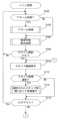
[1.システム全体]
まず、本実施形態におけるシステム全体について説明する。図1は、患者状態表示装置を組み込んだ患者状態表示システム1の全体を説明するための図である。 [1. The entire system]
First, the entire system according to the present embodiment will be described. Fig. 1 is a diagram for explaining the entire patient
まず、患者Pが、ベッド3に載置されるマットレス5の上に横臥している。そして、ベッドには状態検出装置20が設けられている。First, a patient P lies on a mattress 5 placed on a bed 3. A state detection device 20 is provided on the bed.
状態検出装置20は、連続的に患者の生体情報を取得可能な装置であり、例えば患者の体重、体動、血圧、血糖値といった値を取得している。状態検出装置20の一例としては、例えば図1に示すように、ベッド3と、マットレス5の間に設けられても良いし、センサを患者に設けることにより、状態を検出しても良い。また、ベッド装置に直接設ける(例えば、アクチュエータに係る荷重を利用する)構成としてもよい。そして、状態検出装置20は、患者状態表示装置10と接続されている。The condition detection device 20 is a device capable of continuously acquiring biometric information of the patient, such as the patient's weight, body movement, blood pressure, and blood sugar level. As an example of the condition detection device 20, it may be provided between the bed 3 and the mattress 5, as shown in FIG. 1, or a sensor may be provided on the patient to detect the condition. It may also be provided directly on the bed device (for example, by utilizing the load on an actuator). The condition detection device 20 is connected to the patient
患者状態表示装置10は、状態検出装置20と接続されたり、測定装置60と接続されたり、ネットワークを介して他のサーバ装置等に接続されたりしている。また、認証カード65を患者状態表示装置10にかざすことにより、認証処理(ログイン処理)を実現することが可能となる。The patient
ログインは、例えばスタッフ(看護師、医師、介護スタッフ)等の権限を有する者により行われる。ログインすることで、生体情報値や、アラームの内容を確認したり、電子カルテに登録したりすることができる。また、ログイン者毎に権限を設定し、操作ができる範囲を変えることができてもよい。Log-in is performed by authorized personnel, such as staff members (nurses, doctors, care staff, etc.). By logging in, it is possible to check vital signs and alarm contents, and to register them in the electronic medical record. It is also possible to set authority for each login person, and change the scope of operations that can be performed.
ネットワークには、例えば、サーバ30と、電子カルテサーバ40と、端末装置50と、携帯端末装置55とが接続されている。For example, a
サーバ30は、各種サービスを提供するサーバであり、病院内や施設内のLANに接続されていてもよいし、インターネットを介して外部に設けられていてもよい。
電子カルテサーバ40は、患者に関する電子カルテの情報を記憶しているサーバである。通常は、病院内や施設内のネットワークに接続されているが、例えば外部のクラウドサーバを利用しても良い。The electronic medical record server 40 is a server that stores electronic medical record information about patients. It is usually connected to a network within a hospital or facility, but an external cloud server, for example, may also be used.
端末装置50は、ナースステーションや管理室において接続するための端末装置であり、離れていても患者状態表示装置10の状態を把握することが可能となる。また、携帯端末装置55は、例えばLANに無線で接続可能となっており、看護師や介助スタッフ等が患者状態表示装置10の情報を容易に確認することが出来るようになっている。The terminal device 50 is a terminal device for connection at a nurse's station or a management room, and makes it possible to grasp the status of the patient
患者状態表示装置10について、図2を用いて詳しく説明する。患者状態表示装置10は、表示端末1000と、接続装置2000とを含めて構成されている。表示端末1000は、例えばタブレット型の表示端末であり、各種情報を表示したり、各種操作の入力を受け付けたりする。表示端末1000としては、患者状態表示装置10を構成する専用の端末であってもよいし、汎用のタブレット端末に、アプリケーション(プログラム)をインストールして実現する事としてもよい。The patient
接続装置2000は、表示端末1000と各種装置とを接続するための装置である。すなわち、種々の装置のハブ的な役割を果たしている。例えば、図1で示したように、状態検出装置20と接続されることにより、連続的に患者の生体情報を取得可能であり、測定装置60(例えば、体温計)から生体情報を受信したり、患者の身につける装置(例えば腕時計型のウエアラブルの測定装置)から生体情報を受信したりすることも可能である。また、認証カード65が、例えば、通信部220に接続されることにより、認証処理(例えば、患者の認証や、スタッフの認証)も実現可能である。なお、認証方法としては、本実施形態においては近距離無線通信の一例としてNFCを利用しているが、例えば、バーコードや、赤外線、ICタグといった他の方法を利用して認証することとしてもよい。The
また、報知部260が設けられており、例えばエラーが発生した場合に報知することが可能である。更に、LAN(LANは有線LANであっても無線LANであっても良い)を介したサーバ装置等とも接続可能である。この報知部260は、普段は見えない状態であり、報知するときだけ点灯する(表示される)構成であっても良い。また、表示ではなく、例えば、アラーム音や警告音、音声といった音で報知したり、光で報知するといった構成であっても良い。Also, a
なお、本実施形態では、表示端末1000は、接続装置2000の上に置いて使用されることとして説明しているが、表示端末1000と、接続装置2000は分離して使用してもよい。例えば、表示端末1000を持ち出して別の場所で利用したり、接続装置2000をベッド装置に内蔵し、表示端末1000を別に使用したりしてもよい。In this embodiment, the
[2.機能構成]
つづいて、本実施形態における機能構成について、図を用いて説明する。図3は、患者状態表示装置10のうち、表示端末1000と、接続装置2000との機能構成を説明するための図である。 [2. Functional configuration]
Next, the functional configuration of this embodiment will be described with reference to the diagram. Fig. 3 is a diagram for explaining the functional configuration of the
[2.1 表示端末]
まず、表示端末1000の機能構成について説明する。表示端末1000には、制御部100と、記憶部110と、装置通信部150と、操作部160と、表示部170と、LAN通信部180とを有して構成されている。 2.1 Display Terminal
First, a description will be given of the functional configuration of the
制御部100は、表示端末1000の全体を制御するための機能部である。制御部100は、記憶部110に記憶されている各種プログラムを読み出して実行することにより各種機能を実現しており、例えばCPU(Central Process Unit)等により構成されている。The
記憶部110は、表示端末1000の動作に必要な各種プログラムや、各種データが記憶されている機能部である。記憶部110は、例えば、半導体メモリや、HDD(Hard Disk Drive)等により構成されている。The
また、記憶部110には、図4に示すように、生体情報112と、個別電子カルテデータ120と、アラーム閾値テーブル122とが記憶されており、プログラムとして、メインプログラム132と、アラームプログラム134と、患者状態表示プログラム136と、生体情報表示プログラム138と、電子カルテ登録プログラム140と、生体グラフ表示プログラム142とが記憶されている。In addition, as shown in FIG. 4, the
生体情報112は、状態検出装置20から連続的に検出される生体情報である連続生体情報114と、任意のタイミングで測定装置60から受信された測定生体情報116とが記憶されている。なお、連続生体情報や、測定生体情報は、必要に応じて手入力をすることも可能である。The
また、連続生体情報は、検出した分について蓄積情報として蓄積生体情報118にも記憶される。例えば、10秒毎に生体情報値として検出されている場合は、当該生体情報値は蓄積生体情報118にも記憶される。なお、蓄積生体情報118は、所定期間分記憶されても良い。また、時間帯によって記憶される(例えば、就寝時だけ記憶される)という設定にしても良い。The continuous biometric information detected is also stored in the accumulated
ここで、連続生体情報114のデータ構造の一例を図5に示す。本実施形態の連続生体情報114は、状態検出装置20から検出される生体情報の値や、他の患者から状態が検出可能な生体情報の値が記憶されている。Here, an example of the data structure of the continuous
すなわち、連続的に検出可能な値に基づいて記憶されている。例えば、測定日時(例えば、「2015/05/16 20:00」)と、生体情報の種類に対応する値として、脈拍数(例えば、「126」)と、体温(例えば、「37.2」)と、呼吸数(例えば、「15」)と、SpO2(例えば、「99」)とが記憶されている。すなわち、連続生体情報114は、予め決められた測定値をいつでも取得可能である。連続生体情報114を取得する方法としては、状態検出装置20から取得してもよいし、ベッド3に設けた検出装置から取得してもよい。また、患者の体に各種センサを設けて取得してもよい。That is, the information is stored based on continuously detectable values. For example, the measurement date and time (e.g., "2015/05/16 20:00") and the pulse rate (e.g., "126"), body temperature (e.g., "37.2"), respiratory rate (e.g., "15"), and SpO2 (e.g., "99") are stored as values corresponding to the type of biometric information. That is, the continuous
そして、各種取得された生体情報をまとめて連続生体情報として管理可能となっている。これらの生体情報の値は、必要に応じて検出される項目は異なる(例えば、体動検出センサのみを使った場合は、体動状態、睡眠状態、患者姿勢(離床・在床・おきあがり)、脈拍数、呼吸数が連続生体情報として検出される)。The various types of acquired biometric information can be managed together as continuous biometric information. The items detected for these biometric information vary as needed (for example, if only the body movement detection sensor is used, body movement state, sleep state, patient posture (getting out of bed, staying in bed, sitting up), pulse rate, and respiratory rate are detected as continuous biometric information).
測定生体情報116は、体温計や血圧計、体脂肪計といった外部の測定装置から受信される生体情報が記憶される。例えば、図6に示すように、本実施形態の測定生体情報116として、受信日時(例えば、「2015/05/16 20:00」)と、生体情報の種類(例えば、「体温」)毎に、その値(例えば、「37.2」)とが記憶されている。また、例えば、最高血圧(例えば、「159」)と、最低血圧(例えば、「98」)とが記憶されている。Measured
また、検出された連続生体情報114や、測定生体情報116は、所定期間記憶されていてもよい。記憶される期間としては、例えば、1日分や3日分のデータが記憶される。また、連続生体情報114や測定生体情報116は、サーバ30に記憶されることとしても良い。The detected continuous
個別電子カルテデータ120は、患者個人の電子カルテデータが記憶されている。この患者個人の電子カルテデータを集めたものが、電子カルテサーバ40に記憶されている。なお、個別電子カルテデータ120のデータ構造は、電子カルテサーバ40に記憶されているものと同一のものであるため、詳細は後述する。すなわち、患者情報の他に、登録された時点の連続生体情報、測定生体情報等が登録されている。Individual electronic
なお、本実施形態では、記憶部110に記憶されていることとして説明するが、直接電子カルテサーバ40のデータを利用しても良い。この場合は、記憶部110に個別電子カルテデータ120は記憶しなくて良い。In this embodiment, the data is stored in the
アラーム閾値テーブル122は、各種生体情報の値に対してアラーム閾値を記憶している。測定された(受信された)生体情報の値が、アラーム閾値を超えた場合に、報知を実行したり、エラー処理を行ったりする。このアラーム閾値は予め設定されてあってもよいし、任意に設定しても良い。The alarm threshold table 122 stores alarm thresholds for various biometric information values. If the measured (received) biometric information value exceeds the alarm threshold, an alert is issued or error processing is performed. This alarm threshold may be set in advance or may be set arbitrarily.
図7にアラーム閾値テーブル122の一例を示す。図7に示すように、生体情報毎に上限値と下限値とのアラーム閾値が記憶されている。また、アラーム閾値は、アラームの種類によって複数記憶することができる。また、本実施形態では、アラーム閾値により注意レベルと、警告レベルとで2段階記憶している。Figure 7 shows an example of the alarm threshold table 122. As shown in Figure 7, an upper limit and a lower limit alarm threshold are stored for each piece of biometric information. In addition, multiple alarm thresholds can be stored depending on the type of alarm. In this embodiment, the alarm thresholds are stored in two levels: a caution level and a warning level.
例えば、生体情報の一つである「脈拍」については、生体情報値として脈拍数の閾値(注意レベル、警告レベルとなる範囲の閾値)が記憶されている。そして、上限閾値として、注意レベルは「110」、警告レベルは「130」と記憶されている。また、下限閾値として、注意レベルは「60」、警告レベルは「30」と記憶されている。For example, for "pulse", which is one type of biometric information, a pulse rate threshold (threshold for the range of caution levels and warning levels) is stored as a biometric information value. As upper thresholds, the caution level is stored as "110" and the warning level is stored as "130". As lower thresholds, the caution level is stored as "60" and the warning level is stored as "30".
例えば、脈拍数が130以上又は30以下の場合は警告レベルの範囲に含まれていると判断することができる。また、脈拍数が「110以上130未満」又は「30より大きく60以下」の場合は注意レベルの範囲に含まれていると判断することができる。なお、当該閾値を超えた場合(例えば、警告レベルの範囲の脈拍数が130より大きい場合又は30未満の場合)であっても良い。For example, if the pulse rate is 130 or more or 30 or less, it can be determined that it is within the warning level range. Also, if the pulse rate is "110 or more but less than 130" or "greater than 30 but less than 60," it can be determined that it is within the caution level range. Note that this may also be the case when the threshold is exceeded (for example, when the warning level range is a pulse rate greater than 130 or less than 30).
なお、本実施形態では、説明の都合上注意レベルと警告レベルと2段階で説明しているが、それ以上の範囲を設定してもよいことは勿論である。In this embodiment, for convenience of explanation, two levels are used: caution level and warning level, but it goes without saying that a range greater than this may be set.
患者状態識別情報124は、患者の状態について記憶するための情報である。患者状態識別情報を利用して、後述する患者状態識別表示が行われることとなる。本実施形態では、ログアウトから現在までの区間の患者の生体情報に基づいて判断される患者状態識別情報(区間患者状態識別情報)と、現在の患者の生体情報に基づいて判断される患者状態識別情報(現在患者状態識別情報、第1患者状態識別情報)とが記憶される。Patient
ここで、患者状態識別情報には、「正常」「注意」「警告」の状態が記憶される。正常とは、患者の生体情報値が、アラーム閾値範囲内(注意レベルでも警告レベルでもない範囲)に入っている場合である。また、「注意」は、患者の生体情報値のうち、注意レベルの閾値範囲内に入っている生体情報値がある場合である。同様に、「警告」は、患者の生体情報値のうち、警告レベルの閾値範囲内に入っている生体情報値がある場合である。Here, the patient status identification information stores the states "normal," "caution," and "warning." "Normal" refers to a case where the patient's bioinformation value is within the alarm threshold range (a range that is neither the caution level nor the warning level). "Caution" refers to a case where any of the patient's bioinformation values is within the caution level threshold range. Similarly, "warning" refers to a case where any of the patient's bioinformation values is within the warning level threshold range.
また、区間患者状態識別情報は、本実施形態では前回のログアウトから現在までの時の生体情報値に基づいて判断されるが、例えば、前々回のログアウトから前回のログイン時の間の生体情報値に基づいて別の区間患者状態識別情報を更に記憶してもよい。In addition, in this embodiment, the interval patient condition identification information is determined based on the biometric information value from the previous logout to the present, but another interval patient condition identification information may be further stored based on the biometric information value from the time before the previous logout to the previous login, for example.
なお、本実施形態においては、生体情報値のうち、一つでも該当すれば患者状態識別情報は変化することとするが、複数の生体情報値が注意レベルや警告レベルとなったときに患者状態識別情報を更新するとしても良い。また、患者状態識別情報は1つではなく、生体情報毎や、所定のグループ毎に記憶させることとしても良い。例えば、所定のグループとしては、連続生体情報、測定生体情報とを分けて、それぞれの患者の状態に基づいた患者状態識別情報を判定し、記憶してもよい。In this embodiment, the patient condition identification information changes if any one of the vital signs values is met, but the patient condition identification information may be updated when multiple vital signs values reach a caution or warning level. Also, the patient condition identification information may be stored not for one item, but for each piece of vital signs or for each predetermined group. For example, the predetermined group may be divided into continuous vital signs and measured vital signs, and the patient condition identification information based on the condition of each patient may be determined and stored.
また、記憶部110に記憶されているプログラムは、制御部100が読み出して各種機能を実現することが出来る。具体的には、メインプログラム132を読み出して実行することによりメイン機能が、アラームプログラム134を読み出して実行することにより、アラーム機能が、患者状態表示プログラム136を読み出して実行することにより、患者状態表示機能が、生体情報表示プログラム138を読み出して実行することにより、生体情報表示機能が、電子カルテ登録プログラム140を読み出して実行することにより、電子カルテ登録機能が、生体グラフ表示プログラム142を読み出して実行することにより、生体グラフ表示機能がそれぞれ実現される。The programs stored in the
なお、本実施形態においては、各種プログラムは記憶部110に記憶されることとしているが、例えばサーバ側で実行されてもよい。この場合、例えば、サーバに各種情報を送信し、サーバで実行されて出力された結果を受信すれば良い。このように、各プログラムは患者状態表示装置10で実行されても良いし、サーバ側で実行される、例えばASP(Application Service Provider)のような方式で提供されても良い。In this embodiment, the various programs are stored in the
装置通信部150は、後述する装置通信部250と通信を行う為の機能部である。本実施形態では、例えばUSBで接続し、通信が行われることとして説明するが、例えば他の汎用的な接続方法であったり、無線(Bluetooth(登録商標)や、無線LAN等)で接続されたりしてもよい。また、専用の接続インタフェースを設けて、通信を行っても良い。The
操作部160は、利用者からの操作入力を受け付ける機能部であり、例えばタッチパネルにより実現されるソフトウェアキーであったり、キーボード、マウス等の入力装置であったりしてもよい。また、音声入力等を利用してもよい。The
表示部170は、利用者に対して各種情報を表示したり、報知処理を行ったりする機能部である。例えば、液晶ディスプレイ等により実現されている。また、操作部160と、表示部170とが一体に形成されたタッチパネルにより実現されてもよい。The
LAN通信部180は、LANに接続可能なインタフェース部である。Ethernet(登録商標)に接続するためのNIC等により構成される。なお、LAN通信部180は、接続装置2000に設けてもよい。この場合、送信されるデータは、一度装置通信部150(250)を介して接続装置2000に送られた後、ネットワークに送信される。なお、LANに接続するためには、有線で接続されても良いし、無線で接続されても良い。The
[2.2 接続装置]
つづいて、接続装置2000の機能構成について説明する。接続装置2000は、制御部200と、記憶部210と、通信部220と、インタフェース部230と、装置通信部250と、報知部260とを有して構成されている。 2.2 Connection Device
Next, a description will be given of the functional configuration of the
制御部200は、接続装置2000の全体を制御するための機能部である。制御部200は、記憶部210に記憶されている各種プログラムを読み出して実行することにより各種機能を実現しており、例えばCPU(Central Process Unit)等により構成されている。The
記憶部210は、接続装置2000の動作に必要な各種プログラムや、各種データが記憶されている機能部である。記憶部210は、例えば、半導体メモリや、HDD(Hard Disk Drive)等により構成されている。The
通信部220は、他の装置や、認証カードと通信を行う為の機能部である。例えば、近距離無線通信として、NFC(Near Field Communication)通信を行うことが可能である。NFC通信の場合、認証カード65がかざされることにより、認証処理が実行される。また、測定装置60がNFC通信機能を有している場合には、測定装置60をかざすことにより、接続装置2000を介して生体情報を受信可能である。なお、測定装置60としては、例えばスマートフォンのような装置であっても良いし、時計のようなウエアラブル端末装置であっても良い。The
また、通信部220としては、例えば、Bluetooth(登録商標)、TransferJet(登録商標)、ZigBee(登録商標)、RFIDといった何れの方法を用いても良いことは勿論である。また、LAN(無線LAN、有線LAN)等を利用しても良い。Of course, any method such as Bluetooth (registered trademark), TransferJet (registered trademark), ZigBee (registered trademark), or RFID may be used as the
インタフェース部230は、他の装置と通信を行う為の機能部である。例えば、状態検出装置20と接続するための機能部として設けられている。接続するインタフェースとしては、専用のインタフェースで実現されても良いし、USB、RS-232Cといった汎用のインタフェースで実現されても良い。The
装置通信部250は、上述した装置通信部150を介して表示端末1000と、接続装置2000とが通信を行うための機能部である。例えば、USB等を利用して接続されてもよいし、LANを介して接続されてもよい。なお、本実施形態は説明の都合上、各通信部の機能の構成について分けて説明しているが、一つで構成されていてもよい。すなわち、全ての通信をBluetoothで行った場合には、装置通信部250、通信部220、インタフェース部230は一つの機能部で構成される。The
報知部260は、接続装置2000が報知処理を実行する場合に動作する機能部である。例えば、エラー表示を行いたければ、その旨を報知する。報知する手段としては、音、光、表示、振動等の何れかの方法が考えられる。The
[2.3 電子カルテサーバ]
つづいて、電子カルテサーバ40の機能構成について図8を用いて説明する。電子カルテサーバ40は、制御部400と、通信部410と、記憶部450とを有して構成されている。 [2.3 Electronic medical record server]
Next, the functional configuration of the electronic medical record server 40 will be described with reference to Fig. 8. The electronic medical record server 40 is configured to include a
制御部400は、電子カルテサーバ40の全体を制御するための機能部である。制御部400は、記憶部450に記憶されている各種プログラムを読み出して実行することにより各種機能を実現しており、例えばCPU(Central Process Unit)等により構成されている。The
通信部410は、ネットワークに接続するためのインタフェース部である。例えば、Ethernetに接続可能なNICにより構成されている。通信部410を介して他の装置と通信を行うことができる。The
記憶部450は、電子カルテサーバ40の動作に必要な各種プログラムや、各種データが記憶されている機能部である。記憶部450は、例えば、半導体メモリや、HDD(Hard Disk Drive)等により構成されている。The
また、記憶部450には、電子カルテデータ452が記憶されている。電子カルテデータの一例として図9に示す。電子カルテデータは、患者情報が記憶されており、例えば図9のR100に示すように、患者番号、氏名等の基本情報、主治医等の診療情報に併せて、患者の状態等を示した注意情報(R102)、ピクトグラム、測定された生体情報(生体情報値)(R104)が患者毎に記憶されている。The
ここで、注意情報としては、患者の状態を医療従事者、介助者等と専門家に伝えるための注意喚起をするための情報である。例えば、注意喚起に関する情報(鼻かみ禁止等)や、リスクアセスメントとして、褥瘡アセスメントや、転倒リスクアセスメント等が記憶される。これらの情報は、フラグにより管理されてもよいし、文字、アイコン、絵等により管理されてもよい。Here, the warning information is information for alerting the patient's condition to medical staff, caregivers, and other specialists. For example, information on alerts (such as not blowing your nose) and risk assessments such as bedsore assessments and fall risk assessments are stored. This information may be managed by flags, or by text, icons, pictures, etc.
また、より解りやすくするために、ピクトグラム情報が記憶されても良い。ピクトグラムは、日常生活に関する情報を基本としている。当該ピクトグラムが表示されることで、たまたま通りがかった人でも患者への配慮ができることにより、安全・安心を提供するものである。このように、ピクトグラム情報としては、多くの人に対して患者の状態を提供する情報に対し、注意情報は、専門家に対して患者の状態の情報を伝えるものである。To make it easier to understand, pictogram information may also be stored. Pictograms are based on information related to daily life. By displaying the pictograms, even people who happen to be passing by can take care of the patient, providing safety and security. In this way, pictogram information provides information about the patient's condition to many people, while caution information conveys information about the patient's condition to specialists.
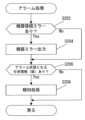
[3.画面(状態)遷移図]
つづいて、本実施形態におけるシステム全体の流れについて、図10の画面遷移図(状態遷移図)を用いて説明する。 [3. Screen (state) transition diagram]
Next, the flow of the entire system in this embodiment will be described with reference to the screen transition diagram (state transition diagram) of FIG.
まず、システムを起動するとアラーム状態にあるか、すなわち、各生体情報値がアラーム閾値を超えている(又はアラーム閾値未満となっている)か否かが判定される。そして、必要に応じてアラーム画面(P100)が表示される。このアラーム画面は、問題が発生していることが確認出来るが、ログインするまでは、エラーの内容は表示されない。これにより、患者や家族に表示すべきではないエラー内容を表示させないでおくことができる。First, when the system is started, it determines whether an alarm state is occurring, that is, whether each vital sign value exceeds the alarm threshold (or is below the alarm threshold). Then, if necessary, an alarm screen (P100) is displayed. This alarm screen allows the user to confirm that a problem has occurred, but the details of the error are not displayed until the user logs in. This makes it possible to avoid displaying error details that should not be shown to the patient or family.
なお、アラーム画面は、電源投入時等のシステム起動時にも表示されるが、随時アラーム状態にあるか否かを判定していてもよい。そして、アラーム状態になった場合、割り込み処理として、アラーム画面に遷移するという構成としてもよい。The alarm screen is also displayed when the system is started, such as when the power is turned on, but it may be determined at any time whether or not an alarm state is occurring. If an alarm state occurs, the system may be configured to transition to the alarm screen as an interrupt process.
つづいて、メイン状態として、患者状態表示画面(P102)が表示される。この画面において、患者の基本情報としてネームプレート情報、ピクトグラム情報、注意情報、エラー状態等が表示される。これにより、看護師や医師等の医療従事者、介助者、介助をしている家族に対して必要な情報を表示することができる。Next, the patient status display screen (P102) is displayed as the main state. On this screen, basic information about the patient, such as nameplate information, pictogram information, warning information, and error status, is displayed. This makes it possible to display necessary information to medical professionals such as nurses and doctors, caregivers, and family members providing care.
患者状態表示画面(P102)は、患者や病院での家族を始め、見舞いに訪れた第三者も見られることから、詳細な情報を表示しない。必要であれば、認証処理を実行し、ログインを行うことにより、ログイン画面(P104)に切り替わる。ログイン画面からは各種画面に遷移することが可能となる。例えば、患者情報を表示可能な患者情報表示画面(P114)、生体情報値を表示させる生体情報表示画面(P106)、生体情報値の履歴を表示させることが可能な生体グラフ表示画面(P108)、当該生体情報値を電子カルテに登録する電子カルテ登録画面(P110)に切り替えることが可能である。The patient condition display screen (P102) does not display detailed information because it can be seen by the patient, his/her family at the hospital, and third parties who come to visit. If necessary, an authentication process is performed and logging in is performed to switch to a login screen (P104). From the login screen, it is possible to transition to various screens. For example, it is possible to switch to a patient information display screen (P114) that can display patient information, a bioinformation display screen (P106) that displays bioinformation values, a biograph display screen (P108) that can display the history of bioinformation values, and an electronic medical record registration screen (P110) that registers the bioinformation values in the electronic medical record.
また、更に、アラーム状態となる条件を設定するアラーム設定・履歴画面(P116)、次にやるべきこと(例えば投薬の指示等)について設定できるリマインダー画面(P112)に切り替えることができる。You can also switch to the alarm settings/history screen (P116) to set the conditions that will trigger an alarm, and the reminder screen (P112) to set what to do next (e.g., medication instructions, etc.).
このように、本実施形態によれば、患者に関する情報を一元的に表示することが可能となり、必要に応じて画面を切り替えることで、適切な情報を表示することが可能となる。また、複数の測定装置の情報を一元的に取得し、電子カルテに登録することで、患者に関する情報を一元的に管理することが可能となる。In this way, according to this embodiment, it is possible to display information about a patient in a centralized manner, and by switching screens as necessary, it is possible to display appropriate information. In addition, by obtaining information from multiple measuring devices in a centralized manner and registering it in the electronic medical record, it is possible to manage information about a patient in a centralized manner.
[4.各処理の説明]
つづいて、本実施形態における各処理について、図を用いて説明する。 [4. Description of each process]
Next, each process in this embodiment will be described with reference to the drawings.
[4.1 メイン処理]
本実施形態におけるメイン処理について図11を用いて説明する。メイン処理は、制御部100が、記憶部110に記憶されたメインプログラム132を読み出して実行することにより実現される処理である。 [4.1 Main Processing]
The main processing in this embodiment will be described with reference to Fig. 11. The main processing is realized by the
まず、アラーム状態にあるか否かが判定される(ステップS102)。具体的には、各バイタル値と、アラーム閾値とを比較し、アラーム閾値を超えていたり、アラーム閾値未満であったりするかを判定し、アラームを出すべきか否かを判定する。そして、アラームを出す必要がある場合には、アラーム処理を実行する(ステップS102;Yes→ステップS104、図12)。First, it is determined whether or not an alarm state has occurred (step S102). Specifically, each vital value is compared with an alarm threshold to determine whether it exceeds or is below the alarm threshold, and whether an alarm should be issued. If an alarm needs to be issued, alarm processing is executed (step S102; Yes -> step S104, FIG. 12).
なお、アラーム閾値を超えているか等は、生体情報の種類によって異なる。また、両方が判断基準により判定する(すなわち、バイタル値が所定の範囲内にあるか否かを判定する)場合もある。Whether or not an alarm threshold has been exceeded depends on the type of vital information. In some cases, both are determined based on criteria (i.e., whether or not a vital value is within a specified range).
つづいて、患者状態を判定し、判定された内容に基づいて患者状態を表示する患者状態表示処理が実行される(ステップS106、図13)。ここで、ログイン認証が行わなければ(又はログイン失敗していれば)、ステップS102から処理が繰り返し実行される(ステップS108;No→ステップS102)。Next, the patient condition is determined, and a patient condition display process is executed to display the patient condition based on the determined contents (step S106, FIG. 13). If login authentication is not performed (or login has failed), the process is repeated from step S102 (step S108; No → step S102).
ここで、ログイン認証が正しく行われた場合には(ステップS108;Yes)、ログイン画面であるスタッフ画面が表示される(ステップS110)。スタッフ画面は、各種処理を選択できる画面である。ここで、スタッフ処理が選択された場合(ステップS112;Yes)には、選択されたスタッフ処理に応じて処理が実行される(ステップS114)。なお、ここで実行される各処理については、後述する。If the login authentication is performed correctly (step S108; Yes), a staff screen, which is a login screen, is displayed (step S110). The staff screen is a screen on which various processes can be selected. If a staff process is selected (step S112; Yes), a process is executed according to the selected staff process (step S114). Each process executed here will be described later.
スタッフ処理が選択されないか(ステップS112;No)、またはスタッフ処理を実行後であっても、ログアウトが実行されなければ、ログイン状態が継続して処理を繰り返し実行する(ステップS116;No→ステップS110)。他方、ログアウトが実行されればログアウトし、ステップS102から処理が繰り返し実行される(ステップS116;Yes→ステップS102)。If the staff process is not selected (step S112; No), or if logout is not executed even after the staff process is executed, the logged-in state continues and the process is executed repeatedly (step S116; No → step S110). On the other hand, if logout is executed, the user is logged out and the process is executed repeatedly from step S102 (step S116; Yes → step S102).
ここで、選択されるスタッフ処理は、図10の画面遷移図で説明したP106~P116に対応する処理である。なお、処理については、処理フローや、画面例を用いて説明する。The staff process selected here corresponds to P106 to P116, which were explained in the screen transition diagram of FIG. 10. The process will be explained using the process flow and screen examples.
[4.2 アラーム処理]
アラーム処理について、図12を用いて説明する。アラーム処理は、図10のP100(図11のステップS104)に対応する処理であり、制御部100が、記憶部110に記憶されたアラームプログラム134を読み出して実行することにより実現される処理である。 4.2 Alarm Processing
The alarm processing will be described with reference to Fig. 12. The alarm processing corresponds to P100 in Fig. 10 (step S104 in Fig. 11), and is realized by the
まず、機器の接続エラーがあるか否かを判定する(ステップS202)。ここで機器の接続エラーがあれば、機器エラーの出力(アラーム)が表示される(ステップS202;Yes→ステップS204)。First, it is determined whether or not there is a device connection error (step S202). If there is a device connection error, an output (alarm) of the device error is displayed (step S202; Yes → step S204).
つづいて、アラーム状態となる生体情報があるか否かを判定する(ステップS202;No→ステップS206又はステップS204→ステップS206)。具体的には、各生体情報値と、アラーム閾値とを比較して、アラーム状態にあるか否かを判定する。そして、アラーム状態となる生体情報の値がある場合には(ステップS206;Yes)、報知処理を実行する(ステップS208)。Next, it is determined whether there is any biometric information that would result in an alarm state (step S202; No → step S206 or step S204 → step S206). Specifically, each biometric information value is compared with an alarm threshold value to determine whether there is an alarm state. Then, if there is any biometric information value that would result in an alarm state (step S206; Yes), a notification process is executed (step S208).
報知処理の一例としては、報知部260から報知処理を行ったり、表示部170においてアラーム画面を表示したりする。なお、このときに詳細情報は、ログインした後(認証された後)でないと、表示しないようにする。Examples of the notification process include performing notification processing from the
なお、アラーム処理については、図11のステップS104で実行されることとして説明したが、一定時間毎に確認し、割り込み処理として実行されることとしても良い。Note that, although the alarm processing has been described as being executed in step S104 of FIG. 11, it may also be executed as an interrupt processing by checking at regular intervals.
このように、アラーム状態となる生体情報があれば、報知処理を行うことでアラームを出力することが可能となる。また、機器接続エラーがある場合でも、アラームの一つとして機器エラーを出力することも可能である。なお、機器接続エラーは別の方法として出力しても良いし、出力しないこととしても良い。In this way, if there is any biometric information that indicates an alarm state, it is possible to output an alarm by performing a notification process. Also, even if there is a device connection error, it is possible to output the device error as one of the alarms. Note that the device connection error may be output as a different method, or it may not be output at all.
また、当該アラームの内容を端末装置50や、携帯端末装置55等に通報する事としてもよい。この場合、例えば注意レベルや警告レベルに応じて通報先を変えたり、通報内容を変えたりしても良い。The contents of the alarm may also be reported to the terminal device 50, the mobile terminal device 55, etc. In this case, the report destination or the report contents may be changed depending on the caution level or warning level, for example.
例えば、患者毎に、患者の状態や生体情報の種類に対応づけてどのように通報を行うかを記憶するテーブルを記憶しておく。このとき、通報設定としては、通報しない「OFF」か、通報するレベルとして注意レベルのときに通報する「注意」、警告レベルのときに通報する「警告」とが記憶される。また、種類によっては、例えば離床しているか否かのように単純に「ON」「OFF」が設定される場合もある。For example, a table is stored that records how to report for each patient in association with the patient's condition and type of vital signs. At this time, the reporting settings stored are "OFF" for no reporting, "Caution" for reporting when the reporting level is at a caution level, and "Warning" for reporting when the reporting level is at a warning level. Depending on the type, "ON" or "OFF" may simply be set, for example, whether the patient has left the bed or not.
また、通報設定に対応して通報先が予め決められていてもよい。例えば、第1通報先として「受持看護師の携帯端末装置」と、ナースステーション等にある「PC」とが設定され、第2通報先として「受持看護師の携帯端末装置」、「PC」に加えて「担当医の携帯端末装置」が決められている。The destination of the report may be determined in advance according to the report setting. For example, the first destination of the report may be set to the "mobile terminal device of the responsible nurse" and a "PC" at a nurse's station, etc., and the second destination of the report may be set to the "mobile terminal device of the responsible nurse," the "PC," and the "mobile terminal device of the attending physician."
この場合、通報設定が「ON」「注意」の場合は第1通報先に通報される。また、通報設定が「警告」の場合は第2通報先に通報される。また、本実施形態において、「受持看護師」や「担当医」については、電子カルテから抽出する。なお、電子カルテとは別に通報先情報として設定しても良い。In this case, if the notification setting is "ON" or "Caution", the notification will be sent to the first notification destination. If the notification setting is "Warning", the notification will be sent to the second notification destination. In this embodiment, the "nurse in charge" and "doctor in charge" are extracted from the electronic medical record. Note that these may also be set as notification destination information separately from the electronic medical record.
このように、予め設定された通報先に対して、通報設定に応じた内容の通報が行われることとしてもよい。なお、患者毎に設定されるのに加えて、共通する通報先が設定されていても良い。例えば、全患者共通として緊急通報先でラピッドレスポンスチームが設定されているとする。この場合、例えば患者の生体情報値が緊急を有する閾値を超えていたり、複数の警告レベルの状態が発生した場合には、緊急通報先に通報が行われるという設定としても良い。In this way, a report based on the report settings may be sent to a preset report destination. In addition to being set for each patient, a common report destination may also be set. For example, a rapid response team may be set as an emergency report destination common to all patients. In this case, for example, if the patient's vital signs exceed a threshold value indicating an emergency or if multiple warning level conditions occur, a report may be sent to the emergency report destination.
また、通報設定は注意レベル、警告レベルの場合に通報すると設定されているが、各レベル以上という設定となっている。例えば、注意レベルに設定されている場合、当該生体情報が注意レベルになった場合に第1通報先に通報が行われ、更に警告レベルになった場合には第2通報先に通報が行われる。すなわち、注意レベルは、警告レベルを含んだものである。なお、設定により、注意レベルのみ通報することとしても良い。The notification settings are set to notify when the biometric information reaches the caution level or warning level, but only when the biometric information reaches or exceeds each level. For example, when the biometric information is set to the caution level, a notification is sent to the first notification destination when the biometric information reaches the caution level, and when the biometric information reaches the warning level, a notification is sent to the second notification destination. In other words, the caution level includes the warning level. It is also possible to set the notification to only be sent when the biometric information reaches the caution level.
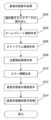
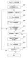
[4.3 患者状態表示処理]
[4.3.1 処理の流れ]
患者状態表示処理について、図13を用いて説明する。患者状態表示処理は、図10のP102(図11のステップ106)に対応する処理であり、制御部100が、記憶部110に記憶された患者状態表示プログラム136を読み出して実行することにより実現される処理である。 4.3 Patient Status Display Processing
[4.3.1 Processing flow]
The patient condition display process will be described with reference to Fig. 13. The patient condition display process corresponds to P102 in Fig. 10 (step 106 in Fig. 11), and is realized by the
まず、個別電子カルテデータ120を読み出す(ステップS302)。なお、この電子カルテのデータを読み出す前に、患者の認証処理を実行しておき、認証された患者のデータを読み出すこととしても良い。First, the individual electronic
つづいて、個別電子カルテデータ120に含まれている基本情報、診療情報から、ネームプレート領域を作成し(ステップS304)、更に注意情報、設定されているピクトグラムからピクトグラム領域を作成する(ステップS306)。Next, a nameplate area is created from the basic information and medical information contained in the individual electronic medical record data 120 (step S304), and a pictogram area is created from the warning information and the set pictograms (step S306).
具体的には、電子カルテサーバ40の電子カルテデータ452と同期された個別電子カルテデータ120に記憶されている氏名、部屋番号、主治医といった基本情報・診療情報等からネームプレート領域(表示画面におけるネームプレート情報が表示される領域)が作成される。Specifically, a nameplate area (area on the display screen where nameplate information is displayed) is created from basic information and medical information such as name, room number, and attending physician stored in the individual electronic
また、個別電子カルテデータ120に記憶されている患者・介助者に対する一般的な注意情報に基づいて、ピクトグラムの表示が作成される。In addition, pictograms are created based on general caution information for patients and caregivers stored in the individual electronic
つづいて、注意情報に基づいた注意喚起領域を作成し(ステップS308)、エラー情報があればエラー情報を生成する(ステップS310)。ここで、注意喚起領域に表示される注意喚起情報は、医療従事者や、介助者といった専門家に対して注意喚起を行う情報に基づいて作成される。したがって、患者や家族といった、医療従事者以外が見ただけでは内容が分からない状態で領域が作成される。また、エラー情報は、アラームに関する情報を含むが、当該内容も同様に患者や家族といった医療従事者以外が見ただけでは解らない状態で領域が作成される。Next, a warning area is created based on the warning information (step S308), and if there is error information, the error information is generated (step S310). Here, the warning information displayed in the warning area is created based on information that warns medical professionals and other professionals such as caregivers. Therefore, the area is created in a state in which the content cannot be understood by people other than medical professionals, such as patients and families, just by looking at it. Also, the error information includes information related to the alarm, but the area is created in a state in which the content cannot be understood by people other than medical professionals, such as patients and families, just by looking at it.
そして、上述したステップで作成された各領域で患者状態表示画面を生成し、表示することとなる(ステップS312)。Then, a patient condition display screen is generated and displayed for each area created in the above steps (step S312).
[4.3.2 患者状態識別表示処理]
つづいて、患者状態識別表示処理を実行し、患者状態表示画面に、患者状態識別表示を行う(ステップS314)。ここで、患者状態識別表示処理について、図14を用いて説明する。 [4.3.2 Patient Status Identification and Display Processing]
Next, a patient condition identification display process is executed, and the patient condition identification display is performed on the patient condition display screen (step S314). Here, the patient condition identification display process will be described with reference to FIG.
まず、ログアウト処理が行われると(ステップS352;Yes)、現在記憶されている患者状態情報が一度クリアされる(ステップS354)。そして、連続生体情報や測定生体情報が受信(入力)される(ステップS356)。First, when the logout process is performed (step S352; Yes), the currently stored patient condition information is cleared (step S354). Then, continuous vital signs and measured vital signs are received (input) (step S356).
連続生体情報や、測定生体情報が受信されると、現在の患者状態(現在患者状態)を決定する(ステップS358)。ここで、現在患者状態は、受信されている全ての生体情報に基づいて「警告」「注意」「正常」の何れかの状態に決定される。具体的には、いずれかの生体情報値がアラーム閾値の注意レベルに含まれていれば「注意」と、いずれかの生体情報値がアラーム閾値の警告レベルに含まれていれば「警告」と決定される。When the continuous vital signs or measured vital signs are received, the current patient status (current patient status) is determined (step S358). Here, the current patient status is determined to be one of "warning," "caution," or "normal" based on all of the received vital signs. Specifically, if any vital sign value is within the caution level of the alarm threshold, the status is determined to be "caution," and if any vital sign value is within the warning level of the alarm threshold, the status is determined to be "warning."
つづいて、区間患者状態.を更新する(ステップS362~S370)。具体的には、まず区間患者状態が「警告」であれば、そのまま「警告」が維持される(ステップS362;Yes)。Then, the section patient status is updated (steps S362 to S370). Specifically, if the section patient status is "Warning," it is maintained as "Warning" (step S362; Yes).
つづいて、区間患者状態が「警告」以外の場合に現在の患者状態が「警告」であれば、区間患者状態を「警告」とする(ステップS362;No→ステップS364;Yes→ステップS366)。すなわち、区間患者状態が「注意」「正常」の場合に、現在患者状態が「警告」になれば、区間患者状態は「警告」となる。Next, if the section patient status is other than "Warning" and the current patient status is "Warning", the section patient status is set to "Warning" (step S362; No → step S364; Yes → step S366). In other words, if the section patient status is "Caution" or "Normal" and the current patient status becomes "Warning", the section patient status becomes "Warning".
また、区間患者状態が「正常」の場合に現在の患者状態が「注意」であれば、区間患者状態を「注意」とする(ステップS362;No→ステップS364;No→ステップS368;Yes→ステップS370)。すなわち、区間患者状態が「正常」の場合に、現在患者状態が「注意」になれば、区間患者状態は「注意」となる。なお、区間患者状態が「注意」の場合、現在患者状態が「正常」「注意」のときは、そのまま「注意」の状態が維持される(ステップS362;No→ステップS364;No→ステップS368;Yes→ステップS370)。In addition, if the section patient status is "normal" and the current patient status is "caution", the section patient status is set to "caution" (step S362; No → step S364; No → step S368; Yes → step S370). That is, if the section patient status is "normal" and the current patient status becomes "caution", the section patient status becomes "caution". Note that if the section patient status is "caution", and the current patient status is "normal" or "caution", the "caution" status is maintained (step S362; No → step S364; No → step S368; Yes → step S370).
また、現在の患者状態が「正常」のままで、区間患者状態が「正常」であれば、そのまま区間患者状態は「正常」なまま維持される(ステップS362;No→ステップS364;No→ステップS368;No)。Also, if the current patient condition remains "normal" and the interval patient condition is "normal", the interval patient condition remains "normal" (step S362; No → step S364; No → step S368; No).
このように、患者状態が「警告」>「注意」>「正常」とより重要度の高い状態になると、区間患者状態は当該状態で更新される。また、一度重要度の高い状態になると、次にクリアされるまで(例えば、次のログイン時のタイミングまで)、当該状態が維持されることとなる。In this way, when the patient status becomes more important, such as "Warning" > "Caution" > "Normal," the section patient status is updated to that status. Also, once a status of higher importance is reached, that status will be maintained until it is cleared again (for example, until the next login).
そして、当該患者状態(区間患者状態、現在患者状態)に基づいて、患者状態識別表示が更新される(ステップS372)。これにより、現在の患者状態と、前回ログアウト時から現在までの最も悪かった状態とをスタッフは容易に確認することができる。Then, the patient status identification display is updated based on the patient status (interval patient status, current patient status) (step S372). This allows staff to easily check the current patient status and the worst status from the time of the previous logout to the present.
そして、再びログイン処理が行わるまで、ステップS356から処理が繰り返し実行される(ステップS374;No→ステップS356)。Then, the process is repeated from step S356 until the login process is performed again (step S374; No → step S356).
ここで、患者状態識別表示の動作の概要について図15を用いて説明する。図15(a)が、画面に表示される患者状態の識別表示の一例である。M102に区間患者状態に基づいた識別表示が、M104に現在患者状態に基づいた識別表示がそれぞれされている。本実施形態では、視認性を考慮し、識別表示M104の方を大きく表示するが、大きさは同じであっても良いし、別の形状、位置としても良い。Here, an overview of the operation of the patient status identification display will be described with reference to FIG. 15. FIG. 15(a) is an example of a patient status identification display displayed on the screen. M102 displays an identification display based on the interval patient status, and M104 displays an identification display based on the current patient status. In this embodiment, the identification display M104 is displayed larger for visibility reasons, but they may be the same size, or may have a different shape or position.
図15(b)は、各患者状態の識別表示の一例を示している。例えば、M110は正常、M112は注意、M114は警告を示している。なお、この表示は色や、動き、形状によって変化させても良い。例えば、色であれば、正常を「白」、注意を「黄」、警告を「赤」と表示しても良い。Figure 15 (b) shows an example of an identification display for each patient condition. For example, M110 indicates normal, M112 indicates caution, and M114 indicates warning. Note that this display may be changed by color, movement, or shape. For example, in terms of color, normal may be displayed as "white," caution as "yellow," and warning as "red."
図15(c)~(e)を用いて、動作について簡単に説明する。なお、前回のログアウト時をt1、現在時点をt2として以下説明する。The operation will be briefly explained using Figures 15(c) to (e). In the following explanation, the previous logout time is t1 and the current time is t2.
図15(c)は、t1の時点には患者状態が「正常」であったが、その後一度「警告」の状態となり、その後「注意」の状態に遷移してt2に至っている。In FIG. 15(c), the patient's condition is "normal" at time t1, then changes to "warning" and then to "caution" at time t2.
この場合、区間患者状態として識別表示M102は、t1以降で一度「警告」となっていることから「警告」の状態で表示されている。また、現在(t2)は「注意」の状態であるので、識別表示M104は「注意」の識別状態が表示されている。In this case, the identification display M102 for the section patient status is displayed in the "Warning" state because it has been set to "Warning" once since t1. Also, since the current state (t2) is "Caution," the identification display M104 is displayed in the "Caution" identification state.
図15(d)は、t1の時点には患者状態が「注意」の状態にあったが、現在(t2)は「正常」の状態となっている状態である。この場合、区間患者状態として識別表示M102は、「注意」の状態の識別表示がされる。また、識別表示M104は、t2の時点が「正常」の状態であるので「正常」の識別表示がされる。In Figure 15 (d), the patient condition was "caution" at time t1, but is now (t2) in a "normal" state. In this case, identification display M102 for the section patient condition is displayed as "caution" status. Also, identification display M104 is displayed as "normal" since the patient condition was "normal" at time t2.
図15(e)は、t1の時点には患者状態は「正常」の状態であったが、途中、「注意」「警告」と遷移した場合の図である。現在(t2)においても、「警告」の状態となっている。このとき、区間患者状態を示す識別表示M102は「警告」となり、現在の患者状態を示す識別表示M104も「警告」となる。Figure 15 (e) shows a case where the patient condition was "normal" at time t1, but transitioned to "caution" and then "warning" along the way. At present (t2), the condition is still "warning." At this time, the identification display M102 indicating the interval patient condition becomes "warning," and the identification display M104 indicating the current patient condition also becomes "warning."
なお、図15では説明の都合上識別表示は2つとして説明しているが、複数設けても良い。例えば、上述した患者状態(全体)の識別表示だけでなく、連続生体情報だけに基づいた識別表示を行っても良い。また、所定の生体情報(例えば、呼吸数等)に対応づけて、特別な識別表示を行っても良い。Note that for convenience of explanation, two identification displays are shown in FIG. 15, but multiple identification displays may be provided. For example, in addition to the identification display of the patient's condition (overall) described above, an identification display based only on continuous vital signs may be provided. Also, a special identification display may be provided in association with specific vital signs (e.g., respiratory rate, etc.).
[4.3.3 画面例]
つづいて、本処理を実行した場合の、画面例を使って説明する。図16は、患者状態表示画面W200の一例である。表示画面W200には、ネームプレート情報として、患者の名前や、主治医の名前などが領域R202、R204に表示されている。これらの項目は、電子カルテに登録されている患者情報から適宜選択されて表示されている。 [4.3.3 Screen Examples]
Next, an example of a screen when this process is executed will be described. Fig. 16 is an example of a patient condition display screen W200. In the display screen W200, the patient's name, the name of the attending physician, and the like are displayed as nameplate information in areas R202 and R204. These items are appropriately selected from the patient information registered in the electronic medical record and displayed.
また、領域R206にはピクトグラム領域として、ピクトグラム等が表示されている。さらに、領域R208には、注意情報の中からとくに注意喚起情報が表示されている。注意喚起情報は、医療従事者や、介護施設の職員といった専門家にしか解らない表示となっている。In addition, pictograms and the like are displayed in region R206 as a pictogram region. Furthermore, in region R208, attention-calling information is displayed among the warning information. The attention-calling information is displayed in a way that only experts, such as medical professionals and staff at care facilities, can understand.
また、R210には、エラーが発生していることを報知している。ここで、エラー内容を表示させるためには、認証処理を実行し、別の画面に切り替えなければならない。これによって、医療従事者や、介助者等といった専門家以外の者がエラーを確認することを防ぐことが出来る。R210 also notifies the user that an error has occurred. In order to display the details of the error, authentication processing must be performed and the screen must be switched to another screen. This makes it possible to prevent people other than medical professionals, caregivers, and other non-experts from seeing the error.
また、状態検出装置20の動作・状態を表示画面W200に表示させてもよい。例えば、領域R212に示すように、状態を表示させる事としても良い。また、センサの接続状態も表示される。これにより、一目でセンサが未接続であったり利用不可になっていたりすることを把握することができる。The operation and status of the status detection device 20 may also be displayed on the display screen W200. For example, the status may be displayed as shown in area R212. The connection status of the sensor is also displayed. This allows the user to know at a glance whether a sensor is not connected or is unavailable.
また、患者状態識別表示が行われている。図16においては、区間患者状態の識別表示がM200に、現在患者状態の識別表示がM202にそれぞれ表示されている。なお、患者状態識別表示は種々の方式が可能であり、例えば、患者名の下に下線を表示し、色や線の太さにより識別表示をしたり、別途アイコンを表示したりしても良い。In addition, the patient status is displayed for identification. In FIG. 16, the interval patient status is displayed in M200, and the current patient status is displayed in M202. Note that the patient status can be displayed in various ways. For example, the patient's name may be underlined, and the patient may be identified by color or line thickness, or a separate icon may be displayed.
また、患者状態識別表示は、本実施形態では連続生体情報、測定生体情報を含めた生体情報全体に対して行っているが、例えば連続生体情報と測定生体情報とを分けて表示しても良いし、生体情報として呼吸だけ別に表示するといった生体情報毎に分けて表示しても良い。In addition, in this embodiment, the patient condition identification display is performed for all biological information, including continuous biological information and measured biological information, but for example, the continuous biological information and measured biological information may be displayed separately, or each piece of biological information may be displayed separately, such as displaying only respiration as biological information.
[4.4 生体情報表示処理]
つづいて、生体情報表示処理について説明する。生体情報表示処理は、図10のP106に対応する処理であり、生体情報表示プログラム138が読み出されて実行されることにより実現される処理である。 [4.4 Biometric information display processing]
Next, the biological information display process will be described. The biological information display process corresponds to P106 in Fig. 10, and is realized by reading and executing the biological
[4.4.1 処理の流れ]
生体情報表示処理について、図17を用いて処理の流れを説明する。まず、電子カルテ(例えば、個別電子カルテデータ120)から、生体情報(値)を読み出す(ステップS402)。 [4.4.1 Processing flow]
The flow of the biological information display process will be described with reference to Fig. 17. First, biological information (values) are read from an electronic medical record (for example, the individual electronic medical record data 120) (step S402).
つづいて、アラーム閾値をアラーム閾値テーブル122から読み出す(ステップS404)。そして、この読み出されたアラーム閾値から各生体情報のアラームグラフを表示する(ステップS406)。ここでアラームグラフは、利用者が見てアラーム閾値が容易に把握出来るような表示であり、上値と下値とのアラーム閾値に基づいて注意レベルの範囲と、警告レベルの範囲とがグラフ表示(識別表示)される。Next, the alarm thresholds are read from the alarm threshold table 122 (step S404). Then, an alarm graph for each piece of vital sign information is displayed based on the read alarm thresholds (step S406). The alarm graph is a display that allows the user to easily understand the alarm thresholds, and the caution level range and warning level range are displayed graphically (displayed identifiable) based on the upper and lower alarm thresholds.
つづいて、前回測定時刻を表示し(ステップS408)、読み出された生体情報に基づく生体情報値を表示する(ステップS410)。Then, the time of the previous measurement is displayed (step S408), and the biometric information value based on the read biometric information is displayed (step S410).
ここで確認情報がある場合には、確認マークを表示する(ステップS412;Yes→ステップS414)。確認マークを表示するタイミングとしては種々のものが考えられるが、例えば本実施形態においては、前回のログアウト時から、今回のログイン時までの間に、注意レベル又は警告レベルに遷移したことがある生体情報の箇所に確認マークを表示する。If there is confirmation information, a confirmation mark is displayed (step S412; Yes -> step S414). Various timings for displaying the confirmation mark are possible, but for example, in this embodiment, the confirmation mark is displayed at the location of biometric information that has transitioned to the caution or warning level between the previous logout and the current login.
なお、確認マークは、利用者(医療従事者や介護スタッフ等)により表示/非表示を生体情報毎に設定可能としても良い。また、マーク表示を、注意レベルに入った場合と、警告レベルとに入った場合とに分けて識別表示する(例えば、注意レベルの場合は黄色円を表示し、警告レベルの場合は赤い円を表示する)こととしても良い。The confirmation mark may be displayed or hidden by the user (medical worker, care staff, etc.) for each piece of biometric information. The mark display may also be differentiated between when the level is at the caution level and when the level is at the warning level (for example, a yellow circle may be displayed for the caution level and a red circle for the warning level).
そして、表示する総ての生体情報について上記処理が終わったら(ステップS416;No)、利用者により処理が選択される。具体的には、生体グラフ表示が選択された場合は生体グラフ表示処理が実行(ステップS418;Yes→ステップS420)され、電子カルテ登録が選択されたら、電子カルテ登録処理が実行(ステップS418;No→ステップS422;Yes→ステップS424)される。Then, when the above processing has been completed for all the biometric information to be displayed (step S416; No), the user selects a processing operation. Specifically, if biometric graph display is selected, the biometric graph display processing is executed (step S418; Yes → step S420), and if electronic medical record registration is selected, the electronic medical record registration processing is executed (step S418; No → step S422; Yes → step S424).
そして、メイン処理に戻る選択がされればメイン処理に戻り(ステップS426;Yes)、それ以外の場合はステップS402から処理が繰り返し実行されることとなる(ステップS426;No)。If a choice is made to return to the main processing, the process returns to the main processing (step S426; Yes); otherwise, the process is repeated from step S402 (step S426; No).
[4.4.2 画面例]
図18に本処理を実行した場合の画面例として表示画面W300を示す。表示画面W300には、各生体情報について生体情報値がそれぞれ表示されている。また、領域R302には、表示されている生体情報値が登録された日時が表示されている。 [4.4.2 Screen Examples]
18 shows a display screen W300 as an example of a screen when this process is executed. The display screen W300 displays the biometric information value for each piece of biometric information. In addition, an area R302 displays the date and time when the displayed biometric information value was registered.
さらに、生体情報値の横には、領域R304にアラーム閾値が解りやすいように表示されている。すなわち、注意レベル、警告レベルが明確となるように、アラーム閾値が表示されている。Furthermore, the alarm threshold is displayed in area R304 next to the biometric information value for easy understanding. In other words, the alarm threshold is displayed so that the caution level and warning level are clear.
また、表示されている生体情報値については、注意レベル、警告レベルの範囲にある場合には、背景が変化する構成としても良い。例えば、R306は、脈拍数として「126bpm」が表示されている。この生体情報値は、注意レベルに含まれているため、背景が注意レベルの色(例えば黄色)等に識別表示される。The background of the displayed biometric value may be changed if it is within the caution or warning level range. For example, R306 displays a pulse rate of "126 bpm." This biometric value is within the caution level, so the background is displayed in a color that corresponds to the caution level (e.g., yellow).
また、生体情報に併せて各種情報を識別表示しても良い。例えば、R308の表示は、脈拍のセンサがONであること(すなわち、脈拍数を連続生体情報として取得可能である)ことが識別表示されている。In addition, various information may be identifiably displayed along with the biometric information. For example, the display of R308 identifiably displays that the pulse sensor is ON (i.e., the pulse rate can be obtained as continuous biometric information).
また、R310は、医療関係者、介護スタッフ等に注意喚起を促す表示である。例えば、前回のログアウト時から、今回のログイン時迄の間に問題があった生体情報について識別表示をするといったことが可能である。これにより、例えば現在患者状態識別情報が「注意」となっている場合、スタッフがログインすることにより呼吸で問題があったことを確認することができる。R310 is also a display that calls the attention of medical personnel, care staff, and the like. For example, it is possible to identify and display any vital signs that have caused problems between the last logout and the current login. This allows staff to log in and confirm that there has been a breathing problem, for example, if the current patient condition identification information is "caution."
[4.5 生体グラフ表示処理]
つづいて、生体グラフ表示処理について説明する。生体グラフ表示処理は、図10のP108に対応する処理であり、生体グラフ表示プログラム142が読み出されて実行されることにより実現される処理である。 [4.5 Biometric graph display processing]
Next, the biological graph display process will be described. The biological graph display process corresponds to P108 in Fig. 10, and is realized by reading and executing the biological
[4.5.1 処理の流れ]
生体グラフ表示処理について、図19を用いて処理の流れを説明する。
まず、患者情報を読み出し(ステップS502)、表示すべき生体情報(値)を1つ読み出す(ステップS504)。つづいて、表示すべきグラフの位置をグラフ表示領域として設定する(ステップS506)。本実施形態の生体グラフ表示処理では、複数の生体情報に基づくグラフが表示されるため、生体情報に応じて順次グラフ表示領域を切り替える。 [4.5.1 Processing flow]
The flow of the biograph display process will be described with reference to FIG.
First, patient information is read (step S502), and one piece of bioinformation (value) to be displayed is read (step S504). Next, the position of the graph to be displayed is set as a graph display area (step S506). In the biograph display process of this embodiment, graphs based on multiple pieces of bioinformation are displayed, so the graph display area is switched sequentially according to the bioinformation.
つづいて、グラフ描画処理を実行することにより(ステップS508)、ステップS506において設定されたグラフ表示領域に生体情報値の遷移が解るようにグラフが表示される。そして、全ての生体情報のグラフが描画するまで処理が繰り返し実行される(ステップS510;No→ステップS504)。Next, a graph drawing process is executed (step S508), and a graph is displayed in the graph display area set in step S506 so that the transition of the bioinformation value can be seen. Then, the process is repeated until all the graphs of the bioinformation are drawn (step S510; No → step S504).
全てのグラフを描画し終わった後(ステップS510;Yes)、生体情報が1つ選択されると(ステップS512;Yes)、個別グラフ画面に切り替わる(ステップS514)。個別グラフ描画とは、選択された生体情報の生体情報値の遷移をグラフで表示する画面であり、グラフ表示領域が1つの生体情報に対応したものとなる。After all the graphs have been drawn (step S510; Yes), when one piece of biometric information is selected (step S512; Yes), the screen switches to an individual graph screen (step S514). Individual graph drawing is a screen that displays the transition of the biometric information value of the selected biometric information in a graph, and the graph display area corresponds to one piece of biometric information.
そして、当該選択された生体情報に基づいてグラフ描画処理が実行される(ステップS516)。そして、グラフ表示の終了操作がなされると、本処理は終了する(ステップS518;Yes)。Then, a graph drawing process is executed based on the selected biometric information (step S516). Then, when an operation to end the graph display is performed, this process ends (step S518; Yes).
[4.5.2 グラフ描画処理]
つづいて、先程のステップS508、ステップS516において実行されるグラフ描画処理について図20を用いて説明する。 [4.5.2 Graph drawing process]
Next, the graph drawing process executed in steps S508 and S516 will be described with reference to FIG.
まず、グラフ表示範囲が設定される(ステップS602)。グラフ表示範囲とは、グラフに表示する範囲を表すものであり、例えば「半日」「1日」「3日」「7日」「4週」といった範囲に基づいて必要な数値が設定される。First, the graph display range is set (step S602). The graph display range indicates the range to be displayed on the graph, and the necessary numerical values are set based on ranges such as "half a day," "one day," "three days," "seven days," and "four weeks."
つづいて、グラフ表示範囲に応じた生体情報値を読み出す(ステップS604)。例えば、半日であれば半日間のグラフとして表示する分の、7日であれば7日間のグラフとして表示する分の生体情報値が読み出される。Next, the bioinformation values corresponding to the graph display range are read out (step S604). For example, if it is half a day, the bioinformation values to be displayed as a half-day graph are read out, and if it is seven days, the bioinformation values to be displayed as a seven-day graph are read out.
なお、生体情報値の読み出し方法としては種々の方法が考えられる。例えば、等間隔の時刻で読み出しても良いし、所定個数の履歴を読み出しても良い。また、期間とプロット数から適切な時間を算出し、読み出しても良い。There are various possible methods for reading out the bioinformation values. For example, they may be read out at equal time intervals, or a predetermined number of histories may be read out. Also, an appropriate time may be calculated from the period and number of plots, and then read out.
つづいて、アラーム領域の識別表示を行い(ステップS606)、生体情報値に基づきグラフを描画する(ステップS608)。アラーム領域の識別表示とは、例えば注意レベルの範囲を黄色、警告レベルの範囲を赤色と表示することになる。Next, the alarm area is identified and displayed (step S606), and a graph is drawn based on the bioinformation value (step S608). The alarm area is identified and displayed, for example, by displaying the caution level range in yellow and the warning level range in red.
また、現在のグラフ描画処理が個別グラフ表示画面であり(ステップS610;Yes)、当該生体情報に対応する蓄積された生体情報(蓄積生体情報)がある場合は、蓄積生体情報に基づいたグラフを重畳して描画する(ステップS612;Yes→ステップS614)。In addition, if the current graph drawing process is an individual graph display screen (step S610; Yes) and there is stored biometric information (stored biometric information) corresponding to the biometric information, a graph based on the stored biometric information is drawn superimposed (step S612; Yes → step S614).
[4.5.3 画面例]
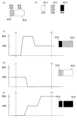
つづいて、生体グラフ表示処理を実行した場合の画面例について図を用いて説明する。図21は、生体情報のグラフを並列して表示した場合の一例である表示画面W400である。 [4.5.3 Screen Examples]
Next, an example of a screen displayed when the biological information graph display process is executed will be described with reference to Fig. 21. Fig. 21 shows a display screen W400 which is an example of a screen displayed when biological information graphs are displayed in parallel.
表示画面W400は、各生体情報値の遷移が表示されている。例えば、表示画面W400には、体温、血圧(最高血圧、最低血圧)、脈拍、呼吸、SpO2の生体情報値の値がグラフとして表示されている、また各生体情報のグラフには、アラーム閾値の領域(注意レベルの範囲、警告レベルの範囲)も併せて表示する。これにより、生体情報値が過去のいつに異常があったのかを容易に把握することができる。The display screen W400 displays the transition of each bioinformation value. For example, the display screen W400 displays the bioinformation values of body temperature, blood pressure (systolic blood pressure, diastolic blood pressure), pulse, respiration, and SpO2 as graphs. The graphs for each piece of bioinformation also display the alarm threshold range (warning level range, alert level range). This makes it easy to know when in the past the bioinformation value was abnormal.
また、画面下では表示範囲を切り替え可能となっている。本実施形態では、「半日」「1日」「3日」「7日」「4週」のタブが表示されており、それぞれ容易に切り替えることができる。The display range can also be switched at the bottom of the screen. In this embodiment, tabs for "Half Day," "1 Day," "3 Days," "7 Days," and "4 Weeks" are displayed, and each can be easily switched between.
なお、このグラフが表示されているときに、生体情報が一つ選択されると、当該生体情報のみを表示した個別グラフが表示されるが、このときの画面例が図22の表示画面W450である。When this graph is displayed and one piece of biometric information is selected, an individual graph showing only that biometric information is displayed; an example of the screen at this time is display screen W450 in Figure 22.
表示画面W450では、生体情報値がP400でプロットされ、当該生体情報値の遷移がグラフL400として表示されている。また、蓄積生体情報に基づいたグラフがL402として表示されている。これにより、測定時刻の間に異常値があったとしても、利用者(医療従事者、介護スタッフ等)は容易に異常を把握出来ることができる。On the display screen W450, the bioinformation value is plotted as P400, and the transition of the bioinformation value is displayed as graph L400. In addition, a graph based on the accumulated bioinformation is displayed as L402. This allows the user (medical worker, care staff, etc.) to easily grasp the abnormality even if there is an abnormal value between the measurement times.
また、併せてアラーム領域が表示されている。例えば、R402に注意レベル(例えば黄色)が、R404に警告レベル(例えば赤色)がそれぞれ識別表示されている。アラーム領域が表示されていることにより、患者の生体情報値が異常値になったか否かを容易に確認することができる。An alarm area is also displayed. For example, a caution level (e.g., yellow) is displayed in R402, and a warning level (e.g., red) is displayed in R404. By displaying the alarm area, it is easy to check whether the patient's vital signs have become abnormal.
なお、図22で表示されている蓄積生体情報に基づいたグラフについて、図21の一覧表示のグラフに重畳して表示しても良いことは勿論である。Of course, the graph based on the accumulated biometric information displayed in FIG. 22 may be superimposed on the graph displayed in the list view in FIG. 21.
[4.6 電子カルテ登録処理]
[4.6.1 処理の流れ]
つづいて、生体情報を電子カルテに登録する電子カルテ登録処理について、図23を用いて説明する。電子カルテ登録処理は、制御部100が、記憶部110に記憶された電子カルテ登録プログラム140を読み出して実行することにより実現される処理である。 [4.6 Electronic medical record registration process]
[4.6.1 Processing flow]
Next, the electronic medical chart registration process for registering biometric information in an electronic medical chart will be described with reference to Fig. 23. The electronic medical chart registration process is realized by the
まず患者情報を読み出し(ステップS702)、当該患者の生体情報を個別電子カルテデータ120から読み出す(ステップS704)。なお、ここで呼び出される生体情報の種類、アラーム閾値等は患者の基本情報(例えば、患者のID)等に基づいて読み出されても良いし、共通の設定としても良い。First, patient information is read (step S702), and the patient's biometric information is read from the individual electronic medical record data 120 (step S704). Note that the type of biometric information and alarm thresholds called up here may be read based on the patient's basic information (e.g., the patient's ID), or may be a common setting.
つづいて、連続生体情報を状態検出装置20から受信し(ステップS706)、当該受信された生体情報の値を表示する(ステップS708)。ここで、生体情報について入力指示があった場合には(ステップS710;Yes)、生体情報値が手動で入力される(ステップS712)。Next, continuous biometric information is received from the condition detection device 20 (step S706), and the value of the received biometric information is displayed (step S708). Here, if an input instruction for the biometric information is given (step S710; Yes), the biometric information value is manually input (step S712).
このとき、生体情報値がアラーム領域にある場合には識別表示を行うこととしても良い。例えば、生体情報値が注意レベルの範囲に含まれていれば黄色、警告レベルの範囲に含まれていれば赤色で背景を表示したり、文字を表示したりする。これにより、現在問題が発生している生体情報であることを医療従事者、介護スタッフは把握することができたり、入力ミス等についても注意喚起を行うことができる。At this time, if the biometric value is in the alarm range, an identification display may be performed. For example, if the biometric value is within the caution level range, the background may be displayed in yellow, and if it is within the warning level range, the background may be displayed in red, or text may be displayed. This allows medical personnel and care staff to know that there is a problem with the biometric information, and also alerts them to input errors, etc.
また、表示画面に表示される連続生体情報としては、状態検出装置20から検出可能な生体情報(生体情報の値)を随時更新して読み出して表示しても良いし、あるタイミングで読み出された生体情報を表示しても良い。The continuous biometric information displayed on the display screen may be the biometric information (value of the biometric information) detectable from the state detection device 20 that is updated at any time and read out and displayed, or the biometric information read out at a certain timing may be displayed.
また、他の測定装置60より、測定生体情報が受信された場合には(ステップS714;Yes)、測定生体情報が記憶される(ステップS716)。この場合、現在表示されている生体情報値が更新されるとともに、個別電子カルテデータ120に記憶される。If measured biometric information is received from another measuring device 60 (step S714; Yes), the measured biometric information is stored (step S716). In this case, the currently displayed biometric information value is updated and stored in the individual electronic
ここで、他の測定装置60より受信される測定生体情報のタイミングは限定されるものではない。本図では一例としてステップS716で説明しているが、予め受信されている測定生体情報を用いてもよい。また、個別電子カルテデータ120(すなわち、電子カルテデータ452)に記憶される測定生体情報も任意のものでよい。例えば、一度測定した値が正しくなければ記憶せず、再測定した値を記憶しても良い。Here, the timing of the measured biological information received from the
そして、電子カルテの登録指示があった場合には(ステップS718;Yes)、電子カルテサーバ40の電子カルテデータ452が登録される(ステップS720)。If an instruction to register the electronic medical record is given (step S718; Yes), the electronic
[4.6.2 画面例]
図24は、本処理を実行した場合の一例である表示画面W500を示した図である。表示画面W500には、各生体情報と、当該生体情報の値とが表示されている。図18と同様に、アラーム閾値が領域R502に表示されており、各生体情報値が注意レベル、警告レベルにある場合には識別表示がR504のようにされている。 [4.6.2 Screen Examples]
Fig. 24 is a diagram showing a display screen W500 as an example when this process is executed. The display screen W500 displays each piece of biometric information and the value of the biometric information. As in Fig. 18, an alarm threshold is displayed in an area R502, and when each biometric information value is at a caution level or a warning level, an identification display is made as shown in R504.
また、領域R506に示すように、前回測定値が併せて表示されることとしても良い。そして、生体情報の上部には、前回測定値が測定された日時も表示されている。これにより、医療従事者や介護スタッフ等は、生体情報値の遷移に気がつくことが可能となる。In addition, as shown in area R506, the previous measurement value may also be displayed. The date and time when the previous measurement value was measured is also displayed above the biometric information. This allows medical personnel, care staff, etc. to notice changes in the biometric information value.
また、表示されている生体情報値については、連続生体情報についてはリアルタイムに更新された値が表示されても良いし、ある時点の値が表示されていても良い。また、電子カルテデータ(個別電子カルテデータ120又は電子カルテデータ452)に記憶されている値を表示してもよい。In addition, for the displayed biometric information values, values updated in real time for continuous biometric information may be displayed, or values at a certain point in time may be displayed. In addition, values stored in the electronic medical record data (individual electronic
そして、この画面から「登録」を選択することで、現在表示されている生体情報値を電子カルテデータに登録(記憶)することができる。また、履歴参照をすることにより、過去の生体情報値を参照することができる。Then, by selecting "Register" from this screen, the currently displayed biometric information value can be registered (stored) in the electronic medical record data. Also, by referencing the history, past biometric information values can be referenced.
[4.7 リマインダー処理]
つづいて、リマインダー処理について説明する。リマインダー処理は、スタッフや医療従事者(看護師等)が次に行うべきことをリマインダーとして登録出来る処理である。例えば、図25は、本処理を実行した場合に表示される表示画面W600の一例である。各種リマインダーとして表示されるべき作業を登録することにより、患者状態表示画面やアラーム表示画面に表示することが可能となる。 4.7 Reminder Processing
Next, the reminder process will be described. The reminder process is a process that allows staff or medical personnel (such as nurses) to register the next thing to be done as a reminder. For example, FIG. 25 is an example of a display screen W600 that is displayed when this process is executed. By registering tasks that should be displayed as various reminders, it is possible to display them on the patient status display screen or the alarm display screen.
[4.8 患者情報表示処理]
つづいて、患者情報表示処理について説明する。患者情報表示処理は、患者に関する情報を表示することが可能な処理である。例えば、患者の基本情報、診療情報、注意情報、ピクトグラム等を表示したり、入力・設定したりすることが可能となる。 [4.8 Patient Information Display Processing]
Next, the patient information display process will be described. The patient information display process is a process that can display information about a patient. For example, it is possible to display, input, and set basic information, medical information, caution information, pictograms, and the like of a patient.
例えば、図26は、本処理を実行した場合に表示される表示画面W700の一例である。表示画面W700は、患者の氏名や、性別、血液型といった基本となる情報(基本情報)を電子カルテより読み出して表示している。For example, FIG. 26 shows an example of a display screen W700 that is displayed when this process is executed. The display screen W700 displays basic information (basic information) such as the patient's name, gender, and blood type, read from the electronic medical record.
[4.9 アラーム設定・履歴処理]
つづいて、アラーム設定・履歴処理について説明する。本処理は、各アラーム閾値を設定したり、アラームの可否について設定したりすることが可能な処理である。また、過去に発生したアラームを履歴として確認することも可能である。 [4.9 Alarm settings and history processing]
Next, the alarm setting and history process will be explained. This process allows you to set each alarm threshold and whether or not to set an alarm. It is also possible to check the history of alarms that have occurred in the past.
図27はアラーム設定・履歴処理を実行した場合に表示される表示画面W800の一例である。表示画面W800は、アラーム閾値をそれぞれ設定出来るようになっている。例えば、上限のアラーム閾値として、注意レベルの範囲の閾値がR804で、警告レベルの範囲の閾値がR802でそれぞれ設定可能である。Figure 27 is an example of a display screen W800 that is displayed when the alarm setting and history process is executed. The display screen W800 allows the setting of individual alarm thresholds. For example, as the upper alarm threshold, the threshold for the caution level range can be set to R804, and the threshold for the warning level range can be set to R802.
また、下限のアラーム閾値として、注意レベルの範囲の閾値がR808で、警告レベルの範囲の閾値がR806でそれぞれ設定可能である。In addition, the lower alarm threshold can be set as the threshold for the caution level range in R808, and the threshold for the warning level range in R806.
また、注意レベル、警告レベルに入った場合にそれぞれアラームを出力するか否かを設定することが可能となる。例えば、R810で示す場合は、アラームとしては出力しない(報知しない)設定となっている。It is also possible to set whether or not an alarm will be output when the caution level or warning level is reached. For example, in the case shown by R810, the setting is that no alarm will be output (no notification will be given).
図28の表示画面W850では、R850により、注意レベルに入ったらアラームを出力する設定となっている。なお、この設定は、例えば音や光といったことを設定できても良いし、注意レベル、警告レベルと別々のアラームを設定するといったことも可能である。In the display screen W850 in FIG. 28, R850 is set to output an alarm when the caution level is reached. Note that this setting may be set to sound or light, for example, or it may be possible to set separate alarms for the caution level and warning level.
また、アラームの設定は、他の画面で設定・変更できても良い。例えば、グラフ表示画面を利用して設定しても良い。具体的な例として、図29の個別グラフ表示画面W880を示す。Also, alarm settings may be set or changed on other screens. For example, they may be set using a graph display screen. As a specific example, the individual graph display screen W880 in FIG. 29 is shown.
図29に示すように、注意レベルの閾値の変更操作ウィンドウをR882、R884に表示してここで操作できても良い。また警告レベルの閾値の変更操作ウィンドウをR886、R888に表示してここで操作できても良い。As shown in FIG. 29, a window for changing the threshold value of the caution level may be displayed in R882 and R884, and the operation may be performed there. Also, a window for changing the threshold value of the warning level may be displayed in R886 and R888, and the operation may be performed there.
[5.患者状態表示装置の構成による効果]
そして、これらの画面が、ベッド3とは別の場所に表示出来るというのが、本実施形態における特徴の一つでもある。これにより、看護師や医師が患者の情報を参照しやすくなったり、ベッドが入れ替わったとしても適切な患者の情報を表示することができる。 [5. Effects of the configuration of the patient condition display device]
One of the features of this embodiment is that these screens can be displayed in a location separate from the bed 3. This makes it easier for nurses and doctors to refer to patient information, and allows appropriate patient information to be displayed even if beds are switched.
とくに、従前であれば、ベッドに設けている表示画面では使い勝手が悪かったり、ベッドサイドに表示しているピクトグラムはその都度更新する必要があったりと使い勝手が悪かった。In particular, previously, the display screens installed on the beds were difficult to use, and the pictograms displayed at the bedside had to be updated each time, making them difficult to use.
また、ベッドで取得出来る情報(例えば、本実施形態の連続生体情報)と、測定装置から取得できる情報(例えば、本実施形態の測定生体情報)とは、別々に管理する必要があった。これらが、患者状態表示装置10(接続装置2000)を介して、全て接続することが可能となり、更に電子カルテに記憶することが可能となる。In addition, information that can be obtained at the bed (e.g., the continuous vital signs in this embodiment) and information that can be obtained from the measuring device (e.g., the measured vital signs in this embodiment) had to be managed separately. All of these can now be connected via the patient condition display device 10 (connection device 2000), and can further be stored in the electronic medical record.
また、図30は、接続装置2000にエラー報知がされている場合の一例である。表示端末1000は、接続装置2000に接続され、一体となってベッドサイドに配置されている。Figure 30 shows an example of a case where an error notification is issued to the
ここで、例えば状態検出装置20と接続できない場合には、領域R900に「センサー接続」と表示される。なお、この領域はエラーが無い場合には何も表示されていない。これにより、表示端末1000がどのような画面であっても、また、仮に表示端末1000が表示不可能な状態(例えば、故障や、表示端末1000が接続されていない場合等)であっても、重要なエラー等を確実に報知することが可能となる。For example, if a connection cannot be made to the status detection device 20, "Sensor connected" is displayed in area R900. Note that nothing is displayed in this area if there is no error. This makes it possible to reliably notify of important errors, etc., regardless of the type of screen displayed by the
また、当該エラー報知は、患者の状態に基づいて報知することとしても良い。この場合、患者や家族等には解らない表示(記号やコード等)を表示することとしても良い。また、報知方法としては、表示するだけでなく、例えば音をならしたり、携帯端末装置55に報知するといったことを行っても良い。The error notification may be based on the patient's condition. In this case, a display (such as a symbol or code) that is not understandable to the patient or family may be displayed. As a notification method, in addition to display, for example, a sound may be played or a notification may be sent to the mobile terminal device 55.
[6.サーバによるサービス提供・他の提供]
なお、上述した実施形態における処理は、説明の都合上患者状態表示装置10が行うこととして説明したが、サーバ30において処理を実行し、患者状態表示装置10で結果を受信する事としても良い。 [6. Service provision by server and other provision]
For convenience of explanation, the processing in the above-described embodiment has been described as being performed by the patient
すなわち、各種プログラム(例えば、メインプログラム132、アラームプログラム134、患者状態表示プログラム136、生体情報表示プログラム138、電子カルテ登録プログラム140、生体グラフ表示プログラム142)を、必要に応じてサーバ30で実行する。患者状態表示装置10からは、生体情報をサーバ30に送信し、例えばWEBブラウザや、専用アプリケーションでサーバ30にアクセスすることで、同様の処理が実現出来る。In other words, various programs (e.g.,
また、患者状態表示装置10も表示端末1000と、接続装置2000とに分けて構成しているが、一体型として専用の患者状態表示装置10として提供してもよい。The patient
表示端末1000と、接続装置2000と分けることにより、表示端末1000は所定の条件を満たすタブレット端末を利用出来るというメリットがある。これにより、市販のタブレット端末、コンピュータを利用したり、スマートフォンを利用したりするといったことも考えられる。By separating the
また、患者状態表示装置10は、ベッド近傍に設けられることが一般的であるが、同一の画面を端末装置50、携帯端末装置55で表示可能である。例えば、看護師が巡回中であっても携帯端末装置55で患者の情報を確認出来たり、ナースステーションにおいて端末装置50を利用することにより、他の患者を含めて一括管理をすることが可能となる。In addition, the patient
また、診療中や検査中においても、端末装置50を用いて生体情報を随時更新することが可能となり、これにより電子カルテの使い勝手が向上することとなる。In addition, it will be possible to update biometric information at any time using the terminal device 50, even during medical treatment or testing, thereby improving the usability of the electronic medical record.
[7.変形例]
以上、この発明の実施形態について図面を参照して詳述してきたが、具体的な構成はこの実施形態に限られるものではなく、この発明の要旨を逸脱しない範囲の設計等も特許請求の範囲に含まれる。 [7. Modifications]
Although an embodiment of the present invention has been described in detail above with reference to the drawings, the specific configuration is not limited to this embodiment, and designs that do not deviate from the gist of the present invention are also included in the scope of the claims.
また、実施形態において各装置で動作するプログラムは、上述した実施形態の機能を実現するように、CPU等を制御するプログラム(コンピュータを機能させるプログラム)である。そして、これら装置で取り扱われる情報は、その処理時に一時的に一時記憶装置(例えば、RAM)に蓄積され、その後、各種ROMやHDDの記憶装置に格納され、必要に応じてCPUによって読み出し、修正・書き込みが行われる。In the embodiments, the programs that run on each device are programs that control the CPU and other devices (programs that make the computer function) to realize the functions of the above-described embodiments. Information handled by these devices is temporarily stored in a temporary storage device (e.g., RAM) during processing, and is then stored in various ROMs or HDD storage devices, from which it is read, modified, and written by the CPU as necessary.
ここで、プログラムを格納する記録媒体としては、半導体媒体(例えば、ROMや、不揮発性のメモリカード等)、光記録媒体・光磁気記録媒体(例えば、DVD(Digital Versatile Disc)、MO(Magneto Optical Disc)、CD(Compact Disc)、BD等)、磁気記録媒体(例えば、磁気テープ、フレキシブルディスク等)等の何れであってもよい。また、ロードしたプログラムを実行することにより、上述した実施形態の機能が実現されるだけでなく、そのプログラムの指示に基づき、オペレーティングシステムあるいは他のアプリケーションプログラム等と共同して処理することにより、本発明の機能が実現される場合もある。The recording medium for storing the program may be any of semiconductor media (e.g., ROM, non-volatile memory cards, etc.), optical recording media, magneto-optical recording media (e.g., DVD (Digital Versatile Disc), MO (Magneto Optical Disc), CD (Compact Disc), BD, etc.), and magnetic recording media (e.g., magnetic tape, flexible disk, etc.). In addition, not only are the functions of the above-mentioned embodiments realized by executing the loaded program, but the functions of the present invention may also be realized by processing in cooperation with an operating system or other application programs, etc., based on the instructions of the program.
また、市場に流通させる場合には、可搬型の記録媒体にプログラムを格納して流通させたり、インターネット等のネットワークを介して接続されたサーバコンピュータに転送したりすることができる。この場合、サーバの記憶装置も本発明に含まれるのは勿論である。When distributing the program on the market, the program can be stored on a portable recording medium and distributed, or transferred to a server computer connected via a network such as the Internet. In this case, the server's storage device is of course included in the present invention.
また、上述した実施形態における各装置の一部又は全部を典型的には集積回路であるLSI(Large Scale Integration)として実現してもよい。各装置の各機能ブロックは個別にチップ化してもよいし、一部又は全部を集積してチップ化してもよい。また、集積回路化の手法はLSIに限らず専用回路又は汎用プロセッサで実現しても良い。また、半導体技術の進歩によりLSIに代替する集積回路化の技術が出現した場合、当該技術による集積回路を用いることも可能であることは勿論である。In addition, some or all of the devices in the above-mentioned embodiments may be realized as LSI (Large Scale Integration), which is typically an integrated circuit. Each functional block of each device may be individually chipped, or some or all of them may be integrated into a chip. The integrated circuit method is not limited to LSI, and may be realized by a dedicated circuit or a general-purpose processor. Furthermore, if an integrated circuit technology that can replace LSI appears due to advances in semiconductor technology, it is of course possible to use an integrated circuit based on that technology.
1 患者状態表示システム
3 ベッド
5 マットレス
10 患者状態表示装置
1000 表示端末
100 制御部
110 記憶部
112 生体情報
114 連続生体情報
116 測定生体情報
118 蓄積生体情報
120 個別電子カルテデータ
122 アラーム閾値テーブル
124 患者状態識別情報
132 メインプログラム
134 アラームプログラム
136 患者状態表示プログラム
138 生体情報表示プログラム
140 電子カルテ登録プログラム
142 生体グラフ表示プログラム
150 装置通信部
160 操作部
170 表示部
180 LAN通信部
2000 接続装置
200 制御部
210 記憶部
220 通信部
230 インタフェース部
250 装置通信部
260 報知部
20 状態検出装置
30 サーバ
40 電子カルテサーバ
400 制御部
410 通信部
450 記憶部
452 電子カルテデータ
50 端末装置
55 携帯端末装置
60 測定装置
65 認証カード
114 Continuous biometric information
116 Measured Biological Information
118 Accumulated
Claims (6)
Translated fromJapanese前記生体情報値に基づいて端末装置に通報する通報手段と、
患者個人の患者状態表示画面を表示可能な表示手段と、
前記生体情報値の正常範囲、注意範囲、警告範囲それぞれ設定可能な設定手段と、
を備え、
前記患者状態表示画面は、前記患者個人のネームプレート、前記患者個人の注意情報、前記患者個人に対して設定されているピクトグラムを含み、
前記受信手段は、連続的に測定された前記患者の第1の生体情報値と、任意のタイミングで測定された前記患者の第2の生体情報値と、を受信可能であり、
前記表示手段は、前記患者状態表示画面を表示しているとき、スタッフが前記表示手段にログイン後のみに前記患者状態表示画面を前記第1及び第2の生体情報値を表示する表示画面に切り替えて表示し、
前記通報手段は、前記スタッフが前記表示手段にログインせずとも前記生体情報値に基づいて前記端末装置に通報し、
前記通報手段は、前記第2の生体情報値が前記注意範囲に含まれるときは、第1の端末装置に通報し、前記第2の生体情報値が前記警告範囲に含まれるときは、前記第1の端末装置と異なる第2の端末装置に通報する表示装置。 A receiving means for receiving a vital sign value of a patient;
a reporting means for reporting to a terminal device based on the biometric information value;
A display means capable of displaying a patient condition display screen for each patient;
a setting means for setting a normal range, a caution range, and a warning range for the biological information value;
Equipped with
the patient condition display screen includes a nameplate of the individual patient, caution information of the individual patient, and a pictogram set for the individual patient,
the receiving means is capable of receiving a first vital sign value of the patient that is continuously measured and a second vital sign value of the patient that is measured at any timing;
the display means,when displaying the patient status display screen, switchesthe patient status display screento a display screen displaying the first and second vital sign values only after a staff member logs in to the display means;
the notification means notifies the terminal device based on the biometric information value without the staff member having to log in to the display means;
The notification means is a display device that notifies a first terminal device when the second bioinformation value is within the caution range, and notifies a second terminal device different from the first terminal device when the second bioinformation value is within the warning range.
前記通報手段は、前記第2の生体情報値に基づいて通報を行う時には、前記通報レベルに基づいて前記テーブルに記憶されている通報先の端末装置に通報を行うときには、前記通報レベルに基づいて前記テーブルに記憶されている通報先の端末装置に通報を行うことを特徴とする請求項1に記載の表示装置。 storing a table capable of storing a notification level and a notification destination according to the type of the biometric information value;
The display device according to claim 1, characterized in that when the notification means issues a notification based on the second biometric information value, the notification means issues a notification to the terminal device to be notified stored in the table based on the notification level.
前記第3の端末装置は、総ての患者に共通して設定される請求項4又は5に記載の表示装置。 The first terminal device and the second terminal device to be the notification destination can be set for each patient,
The display device according to claim 4 or 5, wherein the third terminal device is set in common to all patients.
Priority Applications (1)
| Application Number | Priority Date | Filing Date | Title |
|---|---|---|---|
| JP2023093806AJP7569889B2 (en) | 2020-06-10 | 2023-06-07 | Display device |
Applications Claiming Priority (3)
| Application Number | Priority Date | Filing Date | Title |
|---|---|---|---|
| JP2020100955AJP6983279B2 (en) | 2015-07-10 | 2020-06-10 | Patient status display device |
| JP2021189230AJP7293315B2 (en) | 2015-07-10 | 2021-11-22 | patient status indicator |
| JP2023093806AJP7569889B2 (en) | 2020-06-10 | 2023-06-07 | Display device |
Related Parent Applications (1)
| Application Number | Title | Priority Date | Filing Date |
|---|---|---|---|
| JP2021189230ADivisionJP7293315B2 (en) | 2015-07-10 | 2021-11-22 | patient status indicator |
Publications (2)
| Publication Number | Publication Date |
|---|---|
| JP2023111967A JP2023111967A (en) | 2023-08-10 |
| JP7569889B2true JP7569889B2 (en) | 2024-10-18 |
Family
ID=86896181
Family Applications (1)
| Application Number | Title | Priority Date | Filing Date |
|---|---|---|---|
| JP2023093806AActiveJP7569889B2 (en) | 2020-06-10 | 2023-06-07 | Display device |
Country Status (1)
| Country | Link |
|---|---|
| JP (1) | JP7569889B2 (en) |
Citations (10)
| Publication number | Priority date | Publication date | Assignee | Title |
|---|---|---|---|---|
| JP2002143100A (en) | 2000-11-07 | 2002-05-21 | Matsushita Electric Ind Co Ltd | Nurse call system |
| JP2004503317A (en) | 2000-06-16 | 2004-02-05 | アイシス・イノベーション・リミテッド | System and method for acquiring data |
| JP2005218851A (en) | 2004-01-06 | 2005-08-18 | Toshiba Corp | Communication device, healthcare support system, and healthcare support device |
| JP2005275607A (en) | 2004-03-23 | 2005-10-06 | Fujitsu Ltd | Medical information system |
| JP2008029590A (en) | 2006-07-28 | 2008-02-14 | Seiko Epson Corp | Transmission device with biological information abnormality determination function, transmission device with biological information measurement function, control method for transmission device with biological information abnormality determination function, and biological information abnormality determination program |
| US20090203973A1 (en) | 2008-02-08 | 2009-08-13 | Iseeu Global Limited | Conveying Real Time Medical Data |
| JP2009538706A (en) | 2006-05-31 | 2009-11-12 | コーニンクレッカ フィリップス エレクトロニクス エヌ ヴィ | Displaying trends and trends predicted from mitigation |
| JP2012118782A (en) | 2010-12-01 | 2012-06-21 | Vitas:Kk | Constant display type medical information display system |
| JP2012519547A (en) | 2009-03-04 | 2012-08-30 | マシモ・コーポレイション | Medical monitoring system |
| US20130073306A1 (en) | 2011-09-16 | 2013-03-21 | Jordan Shlain | Healthcare pre-visit and follow-up system |
Family Cites Families (1)
| Publication number | Priority date | Publication date | Assignee | Title |
|---|---|---|---|---|
| JP6217072B2 (en)* | 2012-11-12 | 2017-10-25 | 富士通株式会社 | Patient management support program, system and method |
- 2023
- 2023-06-07JPJP2023093806Apatent/JP7569889B2/enactiveActive
Patent Citations (10)
| Publication number | Priority date | Publication date | Assignee | Title |
|---|---|---|---|---|
| JP2004503317A (en) | 2000-06-16 | 2004-02-05 | アイシス・イノベーション・リミテッド | System and method for acquiring data |
| JP2002143100A (en) | 2000-11-07 | 2002-05-21 | Matsushita Electric Ind Co Ltd | Nurse call system |
| JP2005218851A (en) | 2004-01-06 | 2005-08-18 | Toshiba Corp | Communication device, healthcare support system, and healthcare support device |
| JP2005275607A (en) | 2004-03-23 | 2005-10-06 | Fujitsu Ltd | Medical information system |
| JP2009538706A (en) | 2006-05-31 | 2009-11-12 | コーニンクレッカ フィリップス エレクトロニクス エヌ ヴィ | Displaying trends and trends predicted from mitigation |
| JP2008029590A (en) | 2006-07-28 | 2008-02-14 | Seiko Epson Corp | Transmission device with biological information abnormality determination function, transmission device with biological information measurement function, control method for transmission device with biological information abnormality determination function, and biological information abnormality determination program |
| US20090203973A1 (en) | 2008-02-08 | 2009-08-13 | Iseeu Global Limited | Conveying Real Time Medical Data |
| JP2012519547A (en) | 2009-03-04 | 2012-08-30 | マシモ・コーポレイション | Medical monitoring system |
| JP2012118782A (en) | 2010-12-01 | 2012-06-21 | Vitas:Kk | Constant display type medical information display system |
| US20130073306A1 (en) | 2011-09-16 | 2013-03-21 | Jordan Shlain | Healthcare pre-visit and follow-up system |
Also Published As
| Publication number | Publication date |
|---|---|
| JP2023111967A (en) | 2023-08-10 |
Similar Documents
| Publication | Publication Date | Title |
|---|---|---|
| US11006904B2 (en) | Patient status notification device, notification method in patient status notification device and program | |
| JP6210519B2 (en) | Patient state determination device and patient state determination method | |
| JP7709509B2 (en) | Device | |
| JP7253585B2 (en) | Display device | |
| JP6716211B2 (en) | Patient status display | |
| JP7293315B2 (en) | patient status indicator | |
| JP6514745B2 (en) | Display device, display method in display device, and program | |
| JP7569889B2 (en) | Display device | |
| JP6507198B2 (en) | Patient state determination device and program | |
| JP6983279B2 (en) | Patient status display device |
Legal Events
| Date | Code | Title | Description |
|---|---|---|---|
| A621 | Written request for application examination | Free format text:JAPANESE INTERMEDIATE CODE: A621 Effective date:20230607 | |
| A977 | Report on retrieval | Free format text:JAPANESE INTERMEDIATE CODE: A971007 Effective date:20231115 | |
| A131 | Notification of reasons for refusal | Free format text:JAPANESE INTERMEDIATE CODE: A131 Effective date:20231205 | |
| A521 | Request for written amendment filed | Free format text:JAPANESE INTERMEDIATE CODE: A523 Effective date:20240131 | |
| A131 | Notification of reasons for refusal | Free format text:JAPANESE INTERMEDIATE CODE: A131 Effective date:20240521 | |
| A521 | Request for written amendment filed | Free format text:JAPANESE INTERMEDIATE CODE: A523 Effective date:20240703 | |
| TRDD | Decision of grant or rejection written | ||
| A01 | Written decision to grant a patent or to grant a registration (utility model) | Free format text:JAPANESE INTERMEDIATE CODE: A01 Effective date:20240924 | |
| A61 | First payment of annual fees (during grant procedure) | Free format text:JAPANESE INTERMEDIATE CODE: A61 Effective date:20241007 | |
| R150 | Certificate of patent or registration of utility model | Ref document number:7569889 Country of ref document:JP Free format text:JAPANESE INTERMEDIATE CODE: R150 |