JP7569606B2 - Method for producing carbon material dispersion, carbon material dispersion and device used therefor - Google Patents
Method for producing carbon material dispersion, carbon material dispersion and device used thereforDownload PDFInfo
- Publication number
- JP7569606B2 JP7569606B2JP2020102342AJP2020102342AJP7569606B2JP 7569606 B2JP7569606 B2JP 7569606B2JP 2020102342 AJP2020102342 AJP 2020102342AJP 2020102342 AJP2020102342 AJP 2020102342AJP 7569606 B2JP7569606 B2JP 7569606B2
- Authority
- JP
- Japan
- Prior art keywords
- carbon material
- magnetic
- dispersion
- material dispersion
- metal components
- Prior art date
- Legal status (The legal status is an assumption and is not a legal conclusion. Google has not performed a legal analysis and makes no representation as to the accuracy of the status listed.)
- Active
Links
Images


Classifications
- B—PERFORMING OPERATIONS; TRANSPORTING
- B03—SEPARATION OF SOLID MATERIALS USING LIQUIDS OR USING PNEUMATIC TABLES OR JIGS; MAGNETIC OR ELECTROSTATIC SEPARATION OF SOLID MATERIALS FROM SOLID MATERIALS OR FLUIDS; SEPARATION BY HIGH-VOLTAGE ELECTRIC FIELDS
- B03C—MAGNETIC OR ELECTROSTATIC SEPARATION OF SOLID MATERIALS FROM SOLID MATERIALS OR FLUIDS; SEPARATION BY HIGH-VOLTAGE ELECTRIC FIELDS
- B03C1/00—Magnetic separation
- B03C1/02—Magnetic separation acting directly on the substance being separated
- B03C1/025—High gradient magnetic separators
- B03C1/031—Component parts; Auxiliary operations
- B03C1/033—Component parts; Auxiliary operations characterised by the magnetic circuit
- B03C1/0332—Component parts; Auxiliary operations characterised by the magnetic circuit using permanent magnets
- B—PERFORMING OPERATIONS; TRANSPORTING
- B03—SEPARATION OF SOLID MATERIALS USING LIQUIDS OR USING PNEUMATIC TABLES OR JIGS; MAGNETIC OR ELECTROSTATIC SEPARATION OF SOLID MATERIALS FROM SOLID MATERIALS OR FLUIDS; SEPARATION BY HIGH-VOLTAGE ELECTRIC FIELDS
- B03C—MAGNETIC OR ELECTROSTATIC SEPARATION OF SOLID MATERIALS FROM SOLID MATERIALS OR FLUIDS; SEPARATION BY HIGH-VOLTAGE ELECTRIC FIELDS
- B03C1/00—Magnetic separation
- B03C1/02—Magnetic separation acting directly on the substance being separated
- B03C1/10—Magnetic separation acting directly on the substance being separated with cylindrical material carriers
- B03C1/14—Magnetic separation acting directly on the substance being separated with cylindrical material carriers with non-movable magnets
- B—PERFORMING OPERATIONS; TRANSPORTING
- B03—SEPARATION OF SOLID MATERIALS USING LIQUIDS OR USING PNEUMATIC TABLES OR JIGS; MAGNETIC OR ELECTROSTATIC SEPARATION OF SOLID MATERIALS FROM SOLID MATERIALS OR FLUIDS; SEPARATION BY HIGH-VOLTAGE ELECTRIC FIELDS
- B03C—MAGNETIC OR ELECTROSTATIC SEPARATION OF SOLID MATERIALS FROM SOLID MATERIALS OR FLUIDS; SEPARATION BY HIGH-VOLTAGE ELECTRIC FIELDS
- B03C1/00—Magnetic separation
- B03C1/02—Magnetic separation acting directly on the substance being separated
- B03C1/16—Magnetic separation acting directly on the substance being separated with material carriers in the form of belts
- B—PERFORMING OPERATIONS; TRANSPORTING
- B03—SEPARATION OF SOLID MATERIALS USING LIQUIDS OR USING PNEUMATIC TABLES OR JIGS; MAGNETIC OR ELECTROSTATIC SEPARATION OF SOLID MATERIALS FROM SOLID MATERIALS OR FLUIDS; SEPARATION BY HIGH-VOLTAGE ELECTRIC FIELDS
- B03C—MAGNETIC OR ELECTROSTATIC SEPARATION OF SOLID MATERIALS FROM SOLID MATERIALS OR FLUIDS; SEPARATION BY HIGH-VOLTAGE ELECTRIC FIELDS
- B03C1/00—Magnetic separation
- B03C1/02—Magnetic separation acting directly on the substance being separated
- B03C1/30—Combinations with other devices, not otherwise provided for
- B—PERFORMING OPERATIONS; TRANSPORTING
- B03—SEPARATION OF SOLID MATERIALS USING LIQUIDS OR USING PNEUMATIC TABLES OR JIGS; MAGNETIC OR ELECTROSTATIC SEPARATION OF SOLID MATERIALS FROM SOLID MATERIALS OR FLUIDS; SEPARATION BY HIGH-VOLTAGE ELECTRIC FIELDS
- B03C—MAGNETIC OR ELECTROSTATIC SEPARATION OF SOLID MATERIALS FROM SOLID MATERIALS OR FLUIDS; SEPARATION BY HIGH-VOLTAGE ELECTRIC FIELDS
- B03C1/00—Magnetic separation
- B03C1/32—Magnetic separation acting on the medium containing the substance being separated, e.g. magneto-gravimetric-, magnetohydrostatic-, or magnetohydrodynamic separation
- C—CHEMISTRY; METALLURGY
- C09—DYES; PAINTS; POLISHES; NATURAL RESINS; ADHESIVES; COMPOSITIONS NOT OTHERWISE PROVIDED FOR; APPLICATIONS OF MATERIALS NOT OTHERWISE PROVIDED FOR
- C09C—TREATMENT OF INORGANIC MATERIALS, OTHER THAN FIBROUS FILLERS, TO ENHANCE THEIR PIGMENTING OR FILLING PROPERTIES ; PREPARATION OF CARBON BLACK ; PREPARATION OF INORGANIC MATERIALS WHICH ARE NO SINGLE CHEMICAL COMPOUNDS AND WHICH ARE MAINLY USED AS PIGMENTS OR FILLERS
- C09C1/00—Treatment of specific inorganic materials other than fibrous fillers; Preparation of carbon black
- C09C1/44—Carbon
- C09C1/48—Carbon black
- C09C1/487—Separation; Recovery
- B—PERFORMING OPERATIONS; TRANSPORTING
- B03—SEPARATION OF SOLID MATERIALS USING LIQUIDS OR USING PNEUMATIC TABLES OR JIGS; MAGNETIC OR ELECTROSTATIC SEPARATION OF SOLID MATERIALS FROM SOLID MATERIALS OR FLUIDS; SEPARATION BY HIGH-VOLTAGE ELECTRIC FIELDS
- B03C—MAGNETIC OR ELECTROSTATIC SEPARATION OF SOLID MATERIALS FROM SOLID MATERIALS OR FLUIDS; SEPARATION BY HIGH-VOLTAGE ELECTRIC FIELDS
- B03C2201/00—Details of magnetic or electrostatic separation
- B03C2201/20—Magnetic separation of bulk or dry particles in mixtures
- C—CHEMISTRY; METALLURGY
- C01—INORGANIC CHEMISTRY
- C01P—INDEXING SCHEME RELATING TO STRUCTURAL AND PHYSICAL ASPECTS OF SOLID INORGANIC COMPOUNDS
- C01P2004/00—Particle morphology
- C01P2004/51—Particles with a specific particle size distribution
- C—CHEMISTRY; METALLURGY
- C09—DYES; PAINTS; POLISHES; NATURAL RESINS; ADHESIVES; COMPOSITIONS NOT OTHERWISE PROVIDED FOR; APPLICATIONS OF MATERIALS NOT OTHERWISE PROVIDED FOR
- C09C—TREATMENT OF INORGANIC MATERIALS, OTHER THAN FIBROUS FILLERS, TO ENHANCE THEIR PIGMENTING OR FILLING PROPERTIES ; PREPARATION OF CARBON BLACK ; PREPARATION OF INORGANIC MATERIALS WHICH ARE NO SINGLE CHEMICAL COMPOUNDS AND WHICH ARE MAINLY USED AS PIGMENTS OR FILLERS
- C09C1/00—Treatment of specific inorganic materials other than fibrous fillers; Preparation of carbon black
- C09C1/44—Carbon
- C09C1/48—Carbon black
- C09C1/54—Acetylene black; thermal black ; Preparation thereof
- Y—GENERAL TAGGING OF NEW TECHNOLOGICAL DEVELOPMENTS; GENERAL TAGGING OF CROSS-SECTIONAL TECHNOLOGIES SPANNING OVER SEVERAL SECTIONS OF THE IPC; TECHNICAL SUBJECTS COVERED BY FORMER USPC CROSS-REFERENCE ART COLLECTIONS [XRACs] AND DIGESTS
- Y02—TECHNOLOGIES OR APPLICATIONS FOR MITIGATION OR ADAPTATION AGAINST CLIMATE CHANGE
- Y02E—REDUCTION OF GREENHOUSE GAS [GHG] EMISSIONS, RELATED TO ENERGY GENERATION, TRANSMISSION OR DISTRIBUTION
- Y02E60/00—Enabling technologies; Technologies with a potential or indirect contribution to GHG emissions mitigation
- Y02E60/10—Energy storage using batteries
Landscapes
- Chemical & Material Sciences (AREA)
- Organic Chemistry (AREA)
- Physics & Mathematics (AREA)
- Fluid Mechanics (AREA)
- Carbon And Carbon Compounds (AREA)
- Pigments, Carbon Blacks, Or Wood Stains (AREA)
Description
Translated fromJapanese本発明は、炭素材料分散体の製造方法および炭素材料分散体並びにこれに用いる装置に関する。詳しく述べると本発明は、カーボンブラック、黒鉛、カーボンナノチューブ等の炭素材料が分散媒中に分散された分散体を得るにおいて、不純物としての金属成分を効率良く除去し、特性に優れた炭素材料分散体を製造する技術に関する。The present invention relates to a method for producing a carbon material dispersion, a carbon material dispersion, and an apparatus for use therein. More specifically, the present invention relates to a technology for efficiently removing metal components as impurities in obtaining a dispersion in which carbon materials such as carbon black, graphite, and carbon nanotubes are dispersed in a dispersion medium, and producing a carbon material dispersion with excellent properties.
従来、カーボンブラック、黒鉛、カーボンナノチューブ、カーボンナノファイバー、カーボンファイバー、及びフラ一レン等の炭素材料は、黒色顔料、黒色充填剤、遮光材料、導電材料等として、トナー、印刷インキ、インクジェットインキ、筆記具用インキ、塗料、ゴム組成物、プラスチック組成物、あるいは電池分野、半導体分野等における電極形成材料、導電層形成材料等の幅広い分野で使用されている。Traditionally, carbon materials such as carbon black, graphite, carbon nanotubes, carbon nanofibers, carbon fibers, and fullerenes have been used in a wide range of fields as black pigments, black fillers, light-shielding materials, conductive materials, etc., in toners, printing inks, inkjet inks, writing inks, paints, rubber compositions, plastic compositions, or as electrode-forming materials and conductive layer-forming materials in the battery and semiconductor fields, etc.
上記した炭素材料のうちカーボンブラックを例にとると、カーボンブラックには、(a)油やガスを高温ガス中で不完全燃焼させてカーボンブラックを得るファーネス法により得られるファーネスブラック、(b)天然ガスを燃焼させ、チャンネル鋼に析出させたものを掻き集めて得るチャンネル法により得られるチャンネルブラック、(c)アセチレンガスを熱分解してカーボンブラックを得るアセチレン法によるアセチレンブラック、(d)蓄熱した炉の中でガスの燃焼と分解を繰り返してカーボンブラックを製造するサーマル法によるサーマルブラックなどが知られている。これらのカーボンブラックの原料にはFe、Cuなどの金属成分が含まれている。これらの金属成分はカーボンブラックの製造工程で濃縮され、さらに冷却水や製造設備などからの金属成分の混入もあるため、カーボンブラックは種々の金属成分を含有するものとなる。Among the carbon materials mentioned above, carbon black is an example. (a) Furnace black is obtained by the furnace method, in which oil or gas is incompletely combusted in high-temperature gas to obtain carbon black. (b) Channel black is obtained by the channel method, in which natural gas is burned and the precipitates deposited on channel steel are collected. (c) Acetylene black is obtained by the acetylene method, in which acetylene gas is thermally decomposed to obtain carbon black. (d) Thermal black is obtained by the thermal method, in which gas is repeatedly combusted and decomposed in a heat-storing furnace to produce carbon black. The raw materials for these carbon blacks contain metal components such as Fe and Cu. These metal components are concentrated during the carbon black manufacturing process, and metal components are also mixed in from the cooling water and manufacturing equipment, so carbon black contains various metal components.
そのため、例えば電池分野、半導体分野の如く金属成分の混入を極端に嫌う用途では、それらの金属成分を除去し炭素材料を高純度とすることが求められる。Therefore, in applications where contamination with metal components is extremely unacceptable, such as in the battery and semiconductor fields, it is necessary to remove these metal components and make the carbon material highly pure.
ところで、近年、高いリチウムイオン伝導性を有する固体電解質が開発されている。固体電解質を用いたリチウム二次電池では、有機電解液を用いたリチウム二次電池と比較して、固体電解質と金属リチウムの電荷移動抵抗が非常に小さいため、電池の内部抵抗を小さくすることができる。このような全固体電解質リチウム二次電池を製造する上で、炭素材料は、例えば、電極形成用の導電助剤として分散媒に分散させた炭素材料分散体の形態にて用いられる。全固体電解質リチウム二次電池用途においては、特に、金属成分の存在が電池特性に大きな影響を及ぼすため、できる限り金属成分を除去することが望まれる。In recent years, solid electrolytes with high lithium ion conductivity have been developed. In lithium secondary batteries using solid electrolytes, the charge transfer resistance between the solid electrolyte and metallic lithium is very small compared to lithium secondary batteries using organic electrolyte solutions, so the internal resistance of the battery can be reduced. In manufacturing such all-solid-state electrolyte lithium secondary batteries, the carbon material is used, for example, in the form of a carbon material dispersion dispersed in a dispersion medium as a conductive assistant for forming electrodes. In all-solid-state electrolyte lithium secondary battery applications, it is desirable to remove as many metal components as possible, since the presence of metal components has a significant effect on the battery characteristics.
なお、このような全固体電解質リチウムイオン二次電池に限られず、リチウムイオン二次電池の電極形成用の導電助剤である炭素材料中における金属異物の存在は、デンドライト状態のリチウム金属析出の発生要因であり、内部短絡の原因となるため、その除去はリチウムイオン二次電池全般に望まれることである。The presence of metallic foreign matter in the carbon material that serves as the conductive assistant for forming the electrodes of lithium-ion secondary batteries is a cause of lithium metal precipitation in a dendritic state, which can lead to internal short circuits, and is not limited to such all-solid-state electrolyte lithium-ion secondary batteries. Therefore, their removal is desirable for all lithium-ion secondary batteries.
炭素材料分散体からの金属成分の除去方法としては、従来、例えば、特許文献1に示されるようにカーボンブラックの水性分散液を各種水溶性キレート剤と接触させ、カーボンブラックに含まれる金属成分を溶出させると共にキレート剤に捕捉して液相へ移行させた後、固液分離する方法(特許文献1)、カーボンブラック水性分散液と陽イオン交換樹脂とを接触させて金属を除去する工程を設ける方法(特許文献2)が提案されている。また、炭素物質を対象とするものではないが、非導電性粒子を含むスラリー中より磁性物質を除去する上で、当該スラリーの流束中にマグネットフィルター等の磁石を配して磁性物質を除去する方法(特許文献3)が提案されており、さらに、所定粒度のカーボン粒子、粒子状結着剤及び分散媒を含む二次電池用スラリー組成物の粘度を分散処理によって所定粘度とする分散工程、および前記分散工程により分散処理が行われた前記二次電池用スラリー組成物中の、Fe、NiおよびCrからなる群から選ばれる少なくとも1種の金属を含む粒子状金属成分を、ビッカース硬度が10GPa以上25GPa未満のマグネットカバーを有するマグネットにより除去する方法(特許文献4)が提案されている。As a method for removing metal components from a carbon material dispersion, there have been proposed a method in which an aqueous dispersion of carbon black is brought into contact with various water-soluble chelating agents, as shown in Patent Document 1, to dissolve the metal components contained in the carbon black and capture them in the chelating agent, transferring them to a liquid phase, followed by solid-liquid separation (Patent Document 1), and a method in which a step of contacting the aqueous carbon black dispersion with a cation exchange resin to remove the metals (Patent Document 2). In addition, although not intended for carbon substances, a method has been proposed in which a magnet such as a magnetic filter is placed in the flow of the slurry to remove magnetic substances from a slurry containing non-conductive particles (Patent Document 3).Furthermore, a dispersion process has been proposed in which the viscosity of a slurry composition for secondary batteries containing carbon particles of a predetermined particle size, a particulate binder, and a dispersion medium is adjusted to a predetermined viscosity by dispersion treatment, and a method has been proposed in which particulate metal components containing at least one metal selected from the group consisting of Fe, Ni, and Cr in the slurry composition for secondary batteries that has been dispersed by the dispersion process are removed by a magnet with a magnet cover having a Vickers hardness of 10 GPa or more and less than 25 GPa (Patent Document 4).
しかしながら、特許文献1~4に示されるような従来知られる金属成分の除去方法では、いずれも十分な効果が得られるところまでには至っていない。However, none of the conventional methods for removing metal components, such as those shown in Patent Documents 1 to 4, have been effective enough.
さらに、特許文献1に示されるようにキレート剤を用いる化学的除去法では、添加したキレート剤をカーボンブラックから分離するような処理工程がさらに必要となって、処理が煩雑となり、製造コストがかかるものであった。また、キレート剤を添加できる分散系としては実質的に水系のみに限られ、水分の存在を嫌うような固体電解質リチウム二次電池用途の非水系分散体の処理としては不適であった。Furthermore, in the chemical removal method using a chelating agent as shown in Patent Document 1, an additional processing step is required to separate the added chelating agent from the carbon black, which makes the processing complicated and increases the manufacturing cost. In addition, the dispersion system to which the chelating agent can be added is essentially limited to aqueous systems, and is unsuitable for processing non-aqueous dispersions for use in solid electrolyte lithium secondary batteries, which do not tolerate the presence of moisture.
また特許文献2に示されるようなイオン交換樹脂を用いる場合でも、添加したイオン交換樹脂とカーボンブラックから分離するような処理工程がさらに必要となって、処理が煩雑となり、またイオン交換樹脂が粒子形状であるためその除去の際これに同伴して系外へ取り除かれてしまうカーボンブラックの量が多くなり、歩留まりが悪いものとなる虞れがあった。Even when using an ion exchange resin as shown in Patent Document 2, an additional processing step is required to separate the added ion exchange resin from the carbon black, making the processing complicated. In addition, because the ion exchange resin is in a particulate form, a large amount of carbon black is removed from the system along with the ion exchange resin when it is removed, which may result in a poor yield.
また特許文献3および4に示されるような方法では、所定粘度の炭素材料スラリーを調製の後、その流路に、格子状、スリット状等に配された磁石で構成されるマグネットフィルターを配してスラリーを通過させるなどして、金属成分を除去することが提案されているが、炭素材料を含有するスラリー中に含まれる金属成分(磁性体)は、磁界に置かれてもスラリーの流れに抗して磁石に近接できず付着できなかったり、あるいは磁石に付着したとしても後からくるスラリー中の炭素材料の粒子との衝突によって磁石より再び離れてしまったりするため、効率的に金属成分を除去することが困難であった。炭素材料中に混入する金属成分としては、炭素材料の粉粒子とは独立した金属粒子として存在するものもあるが、炭素材料の粉粒子中に含まれているものも多くある。特に後者の炭素材料の粉粒子中に含まれている金属成分は、当該金属成分を含む炭素材料の粉粒子自体の分散媒中での動きが制限されることによって、このように湿式条件下で磁気吸引を行っても、磁石に捕捉されずにスラリー中に残留するものが生じ、高効率で金属成分を除去し得ない虞れが残るものであった。In addition, in the methods shown in
従って本発明は、炭素材料中における金属成分を効率良くかつ確実に除去し、製品品質が極めて高く、安定した電気的特性を発揮し得る炭素材料分散体の製造方法、およびこれにより得られる炭素材料分散体並びにこれに用いる装置を提供することを課題とする。本発明はまた、複雑な工程や廃液処理などを必要とせずに低コストで炭素材料中から金属成分を効率良く分離し、高品質な炭素材料分散体を得ることのできる炭素材料分散体の製造方法、およびこれにより得られる炭素材料分散体並びにこれに用いる装置を提供することを課題とする。本発明はさらに、リチウムイオン二次電池製造用の導電助剤分散液として好適な炭素材料分散体の製造方法、およびこれにより得られる炭素材料分散体並びにこれに用いる装置を提供することを課題とする。Therefore, the objective of the present invention is to provide a method for producing a carbon material dispersion that efficiently and reliably removes metal components from a carbon material, has extremely high product quality, and can exhibit stable electrical properties, as well as a carbon material dispersion obtained thereby and an apparatus for use therein. Another objective of the present invention is to provide a method for producing a carbon material dispersion that efficiently separates metal components from a carbon material at low cost without requiring complicated processes or waste liquid treatment, and can obtain a high-quality carbon material dispersion, as well as a carbon material dispersion obtained thereby and an apparatus for use therein. A further objective of the present invention is to provide a method for producing a carbon material dispersion that is suitable as a conductive assistant dispersion for manufacturing lithium-ion secondary batteries, as well as a carbon material dispersion obtained thereby and an apparatus for use therein.
上記課題を解決するために本発明者らは、鋭意検討および研究を進めた結果、炭素材料が粉粒状の乾式状態において、当該炭素材料の粉粒体を回転する磁気ロール表面上に適用し炭素材料より金属成分を除去し、さらに金属成分を除去した炭素材料を分散媒中へ分散させて炭素材料分散体を調製した後に、当該炭素材料分散体中に磁石体を配して当該炭素材料分散体中より金属成分を湿式にて除去する工程を設けることで、簡単な操作で、効率よくかつ歩留まり良く、金属成分を除去し精製された炭素材料分散体を得ることができることを見出し本発明に至ったものである。In order to solve the above problems, the inventors have conducted intensive research and studies, and as a result have discovered that a carbon material dispersion from which metal components have been removed can be obtained efficiently and with a good yield with a simple operation by applying the carbon material powder, when the carbon material is in a powdered, dry state, to the surface of a rotating magnetic roll to remove metal components from the carbon material, and then dispersing the carbon material from which the metal components have been removed in a dispersion medium to prepare a carbon material dispersion, and then disposing a magnet body in the carbon material dispersion to wet remove the metal components from the carbon material dispersion. This led to the present invention.
すなわち、上記課題を解決する本発明は、炭素材料が粉粒状の乾式状態において、当該炭素材料の粉粒体を回転する磁気ロール表面上に適用し炭素材料より金属成分を除去する第1磁気選別工程と、さらに当該第1磁気選別工程において金属成分を除去した炭素材料を分散媒中へ分散させた炭素材料分散体を調製後に、当該炭素材料分散体中に磁石体を配して当該炭素材料分散体中より金属成分を除去する第2磁気選別工程を有することを特徴とする炭素材料分散体の製造方法である。In other words, the present invention, which solves the above problems, is a method for producing a carbon material dispersion, which is characterized by having a first magnetic separation step in which the carbon material, in a powdered, dry state, is applied to the surface of a rotating magnetic roll to remove metal components from the carbon material, and a second magnetic separation step in which a carbon material dispersion is prepared by dispersing the carbon material from which the metal components have been removed in the first magnetic separation step in a dispersion medium, and then a magnet is placed in the carbon material dispersion to remove the metal components from the carbon material dispersion.
本発明に係る炭素材料分散体の製造方法の一実施形態においては、前記第1磁気選別工程では、炭素材料の粉粒体の搬送方向と順方向に回転する磁気ロールを用いるものが示される。In one embodiment of the method for producing a carbon material dispersion according to the present invention, the first magnetic separation step uses a magnetic roll that rotates in the same direction as the transport direction of the carbon material powder particles.
本発明に係る炭素材料分散体の製造方法の一実施形態においては、第1磁気選別工程で用いる前記磁気ロールとして径方向着磁とされた5000~20000ガウスの磁石体を有するものを用い、また前記第2磁気選別工程で用いる磁石体としては炭素材料分散体の流路内に流路の軸方向に概略沿って配置された5000~20000ガウスの磁石体を用いるものが示される。In one embodiment of the method for producing a carbon material dispersion according to the present invention, the magnetic roll used in the first magnetic separation step has a radially magnetized magnet body of 5,000 to 20,000 gauss, and the magnetic body used in the second magnetic separation step has a magnet body of 5,000 to 20,000 gauss arranged in the flow path of the carbon material dispersion roughly along the axial direction of the flow path.
本発明に係る炭素材料分散体の製造方法の一実施形態においては、前記第2磁気選別工程にかけられる炭素材料分散体の粘度が10~1000mPa・sであるものが示される。In one embodiment of the method for producing a carbon material dispersion according to the present invention, the viscosity of the carbon material dispersion subjected to the second magnetic separation process is 10 to 1000 mPa·s.
本発明に係る炭素材料分散体の製造方法の一実施形態においては、前記分散媒体が有機溶媒であるものが示される。In one embodiment of the method for producing a carbon material dispersion according to the present invention, the dispersion medium is an organic solvent.
上記課題を解決する本発明はまた、炭素材料を分散媒中に分散させた炭素材料分散体であって、分散体中の炭素材料含有率が10~25質量%であり、かつ磁性金属成分が炭素材料に対して質量分率で1×10⁻⁷以下であり、また、分散媒が有機溶媒であることを特徴とする炭素材料分散体により達成される。 The present invention for solving the above-mentioned problems is also achieved by a carbon material dispersion in which a carbon material is dispersed in a dispersion medium, characterized in that the carbon material content in the dispersion is 10 to 25 mass %, the magnetic metal component is 1 x 10⁻⁷ or less in mass fraction relative to the carbon material, and the dispersion medium is an organic solvent.
本発明に係る炭素材料分散体は、前記した第1磁気選別工程および前記第2磁気選別工程を経て得られたものであるものが示される。The carbon material dispersion according to the present invention is obtained by the first magnetic sorting process and the second magnetic sorting process.
上記課題を解決する本発明はさらに、表面が炭素材料との接触面となる回転する中空円筒部および、前記中空円筒部の内部空間内において、前記中空円筒部の内周面に対し近接して配置された円弧状の磁化対向面を有する磁石体部から構成される磁気ロールと、
前記磁気ロールの回転する中空円筒部に対して、粉粒状の炭素材料を供給する上流側に位置する供給経路と、
前記磁気ロールの回転する中空円筒部に対して下流側において、前記中空円筒部の表面に付着せずに落下する炭素材料の粉粒群を回収する回収部とを少なくとも有することを特徴とする、炭素材料の乾式精製装置により達成される。 The present invention, which solves the above problems, further includes a magnetic roll including a rotating hollow cylindrical portion whose surface is a contact surface with a carbon material, and a magnet body portion having an arc-shaped magnetized opposing surface disposed adjacent to an inner peripheral surface of the hollow cylindrical portion within an internal space of the hollow cylindrical portion;
a supply path located upstream for supplying a powdered carbon material to the rotating hollow cylindrical portion of the magnetic roll;
This can be achieved by a dry refining apparatus for carbon materials, which is characterized by having at least a recovery section downstream of the rotating hollow cylindrical section of the magnetic roll, which recovers powder particles of the carbon material that fall without adhering to the surface of the hollow cylindrical section.
本発明に係る上記炭素材料の乾式精製装置の一実施形態においては、前記供給経路が、前記磁気ロールの最頂部位置近傍に終端部を有し、磁気ロールに対し略接線方向から粉粒状の炭素材料を搬送するベルトコンベア部を有するものが示される。In one embodiment of the dry refining apparatus for carbon materials according to the present invention, the supply path has a terminal end near the topmost position of the magnetic roll and has a belt conveyor section that transports the powdered carbon material in a direction approximately tangential to the magnetic roll.
本発明に係る上記炭素材料の乾式精製装置の一実施形態においては、前記ベルトコンベア部の上を搬送される炭素材料の粉粒体を所定厚み以下の層として、前記磁気ロールの中空円筒部へと供給するために、粉粒体の供給量を規制する規制子が設けられているものが示される。In one embodiment of the dry refining apparatus for carbon materials according to the present invention, a regulator is provided to regulate the amount of powder and granular material supplied so that the powder and granular material transported on the belt conveyor section is supplied to the hollow cylindrical section of the magnetic roll as a layer having a thickness of a predetermined value or less.
本発明に係る上記炭素材料の乾式精製装置の一実施形態においては、前記磁石体の円弧状の磁化対向面が90°~270°の角度範囲を有するものであるものが示される。In one embodiment of the dry refining device for carbon materials according to the present invention, the magnet body has an arc-shaped magnetized opposing surface with an angle ranging from 90° to 270°.
本発明に係る上記炭素材料の乾式精製装置の一実施形態においては、前記磁気ロールの最頂部位置を0°としたとき、前記磁石体の円弧状の磁化対向面が、前記中空円筒部の回転方向に順方向で、-20°~30°の位置より開始され、かつ少なくとも275°~315°の位置には存在しないものであるものが示される。In one embodiment of the dry refining device for carbon materials according to the present invention, when the topmost position of the magnetic roll is set to 0°, the arc-shaped magnetized opposing surface of the magnet body starts at a position between -20° and 30° in the forward direction relative to the rotation direction of the hollow cylindrical portion, and does not exist at least at a position between 275° and 315°.
本発明に係る上記炭素材料の乾式精製装置の一実施形態においては、前記磁石体が、径方向着磁とされた5000~20000ガウスのものであることが示される。In one embodiment of the dry refining device for carbon materials according to the present invention, the magnet body is radially magnetized at 5,000 to 20,000 gauss.
上記課題を解決する本発明はさらに、炭素材料の精製システムであって、上流側の乾式精製装置と下流側の湿式精製装置とを有し、
前記乾式精製装置は、表面が炭素材料との接触面となる回転する中空円筒部および、前記中空円筒部の内部空間内において、前記中空円筒部の内周面に対し近接して配置された円弧状の磁化対向面を有する磁石体部から構成される磁気ロールと、
前記磁気ロールの回転する中空円筒部に対して、粉粒状の炭素材料を供給する上流側に位置する供給経路と、
前記磁気ロールの回転する中空円筒部に対して下流側において、前記中空円筒部の表面に付着せずに落下する炭素材料の粉粒群を回収する回収部とを少なくとも有して構成され、
また、前記湿式精製装置は、前記乾式精製装置の回収部に回収された乾式磁選された炭素材料の粉粒群に分散媒を添加して調製される炭素材料分散液を流通させる流路内に、この流路の軸方向に概略沿って磁石体を配し、当該磁石体の表面ないしは当該磁石体の磁場により印加された表面と接する通液路が形成された磁気フィルターを有して構成されるものである炭素材料の精製システムによっても達成される。 The present invention for solving the above problems further provides a purification system for a carbon material, the purification system comprising an upstream dry purification device and a downstream wet purification device,
The dry refining apparatus includes a magnetic roll including a rotating hollow cylindrical portion whose surface is a contact surface with the carbon material, and a magnet body portion having an arc-shaped magnetized opposing surface disposed in the internal space of the hollow cylindrical portion and adjacent to the inner peripheral surface of the hollow cylindrical portion;
a supply path located upstream for supplying a powdered carbon material to the rotating hollow cylindrical portion of the magnetic roll;
a recovery section for recovering powder particles of the carbon material that falls without adhering to the surface of the hollow cylindrical section, the powder particles being located downstream of the rotating hollow cylindrical section of the magnetic roll,
The wet refining apparatus can also be achieved by a carbon material refining system that is configured by arranging a magnet body roughly along the axial direction of a flow path through which a carbon material dispersion liquid, which is prepared by adding a dispersion medium to a powder mass of the dry magnetically separated carbon material recovered in a recovery section of the dry refining apparatus, flows, and the magnet body is provided in the flow path, and a liquid passage is formed that comes into contact with the surface of the magnet body or a surface to which a magnetic field is applied by the magnet body.
本発明によれば、金属成分を極限的に除去し精製された高品質の炭素材料分散体が得られるため、例えば、当該炭素材料分散体を、例えば、二次電池の電極形成用の導電助剤材料として用いることにより、高品質の安定した二次電池を製造することが可能となる。According to the present invention, a high-quality carbon material dispersion can be obtained that is purified by removing metal components to the greatest extent possible. For example, by using the carbon material dispersion as a conductive additive material for forming electrodes in secondary batteries, it becomes possible to manufacture high-quality, stable secondary batteries.
また、粒子状金属成分が電池内に存在すると、内部短絡や充電時の溶解・析出による自己放電増大の問題等が生じるが、本発明に係る炭素材料分散体を用いることでこのような問題が解消され、電池のサイクル特性や安全性が向上する。In addition, the presence of particulate metal components in a battery can cause problems such as internal short circuits and increased self-discharge due to dissolution and precipitation during charging. However, the use of the carbon material dispersion according to the present invention can eliminate such problems, improving the cycle characteristics and safety of the battery.
以下、本発明を実施形態に基づき詳細に説明する。
<炭素材料分散体の製造方法>
本発明の第1の観点に係る炭素材料分散体の製造方法は、炭素材料が粉粒状の乾式状態において、当該炭素材料の粉粒体を回転する磁気ロール表面上に適用し炭素材料より金属成分を除去する第1磁気選別工程と、さらに当該第1磁気選別工程において金属成分を除去した炭素材料を分散媒中へ分散させた炭素材料分散体を調製後に、当該炭素材料分散体中に磁石体とを配して当該炭素材料分散体中より金属成分を除去する第2磁気選別工程を有することを特徴とする。 Hereinafter, the present invention will be described in detail based on embodiments.
<Method of producing carbon material dispersion>
The method for producing a carbon material dispersion according to a first aspect of the present invention is characterized by comprising a first magnetic separation step in which the powder of the carbon material, when the carbon material is in a powdered, dry state, is applied onto the surface of a rotating magnetic roll to remove metal components from the carbon material, and further comprising a second magnetic separation step in which a carbon material dispersion is prepared by dispersing the carbon material from which the metal components have been removed in the first magnetic separation step into a dispersion medium, and then a magnet body is placed in the carbon material dispersion to remove the metal components from the carbon material dispersion.
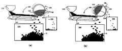
図1は、本発明の第1の観点に係る炭素材料分散体の製造方法を実施する上で用いられる炭素材料の精製システムの一実施形態の全体構成を模式的に示すブロック図である。また、図2、図3(a)、(b)および図4(a)、(b)はそれぞれ、同精製システムにおける乾式精製装置のそれぞれ別の実施形態における構造を模式的に示す断面図である。なお、図1~4においては、視覚的な理解を容易とするために、炭素材料、金属粒子等の各材料や部材の大きさ、寸法等は誇張して描かれており、この点に関して図面に示される内容に制限されるものではないことは理解されるべきである。Figure 1 is a block diagram showing a schematic overall configuration of one embodiment of a carbon material purification system used in carrying out the method for producing a carbon material dispersion according to the first aspect of the present invention. Also, Figures 2, 3(a) and 3(b), and 4(a) and 4(b) are cross-sectional views showing schematic structures of different embodiments of a dry purification device in the purification system. Note that in Figures 1 to 4, the sizes and dimensions of each material and member, such as the carbon material and metal particles, are exaggerated to facilitate visual understanding, and it should be understood that the contents shown in the drawings are not limited in this regard.
まず、本発明の第1の観点に係る炭素材料分散体の製造方法の概要を、この精製システムの一実施形態を用いて実施する場合を例にとり簡単に説明する。First, we will briefly explain the outline of the method for producing a carbon material dispersion according to the first aspect of the present invention, taking as an example a case where the method is carried out using one embodiment of this purification system.
図1に示す精製システムの一実施形態は、上流側の乾式精製装置100と下流側の湿式精製装置300を有してなり、炭素材料Cが粉粒状の乾式状態において、当該炭素材料の粉粒体を回転する磁気ロール130の表面上に適用され、炭素材料より金属成分を除去する第1磁気選別工程が行われ、第1選別工程において選別された炭素材料Cは、次いで、分散体調製装置200において分散媒体と混合されて炭素材料分散体Dが調製され、調製された炭素材料分散体Dを湿式精製装置300に導入し、当該炭素材料分散体Dの流れの中に磁石体310とを配して当該炭素材料分散体D中より金属成分Mを除去する第2磁気選別工程が実施される。One embodiment of the refining system shown in FIG. 1 has an upstream
本発明の第1の観点に係る炭素材料分散体の製造方法において、処理対象となる炭素材料Cとしては、導電性を有する炭素材料であり、粉粒状の形態を呈し得るものであれば特に限定されるものではないが、グラファイト、カーボンブラック(CB)、カーボンナノチューブ(CNT)、カーボンナノファイバー(CNF)、カーボンファイバー(CF)、フラーレン、天然黒鉛等が挙げられ、これらを単独で、もしくは2種類以上併せて使用することができる。炭素材料としては、特にCBが好ましい。さらにCBとしては、例えば、ファーネスブラック、チャンネルブラック、アセチレンブラック、サーマルブラック等が挙げられ、そのいずれを用いることが可能である。このうち例えば、アセチレンブラックは、その製法上で金属成分含有量が本来的に低いものとなるが、本発明に係る炭素材料分散体の製造方法を経ることによって、得られるアセチレンブラック分散体は、さらに大きく金属成分含有量を低減したものとし得る。In the method for producing a carbon material dispersion according to the first aspect of the present invention, the carbon material C to be treated is a conductive carbon material that is not particularly limited as long as it can be in the form of a powder or granule, and examples of such materials include graphite, carbon black (CB), carbon nanotubes (CNT), carbon nanofibers (CNF), carbon fibers (CF), fullerenes, and natural graphite, and these materials can be used alone or in combination of two or more. As the carbon material, CB is particularly preferred. Examples of CB include furnace black, channel black, acetylene black, and thermal black, and any of these can be used. Of these, for example, acetylene black has an inherently low metal component content due to its manufacturing method, but by passing through the method for producing a carbon material dispersion according to the present invention, the acetylene black dispersion obtained can have an even greater reduction in metal component content.
ここで本明細書において炭素材料の「粉粒状」の形態とは、少なくとも、混在する金属成分の除去する際に、第1磁気選別工程の磁気ロールに対して適用可能な大きさのものであれば特に限定されない。例えば、平均粒子径10~60nm程度の粒子径を呈している一次粒子、このような一次粒子が凝集等して平均粒子径1~1000μm程度の二次粒子を呈しているもの、あるいはさらに圧縮処理や造粒処理により平均粒子径0.5~5mm程度の加工された粒子とされたものなどが含まれ得る。さらに、その形状としても、特に限定されるものではなく、概略球状のものに限られず、楕円状、薄片状、針状ないし短ファイバー状、不定形等が含まれ得る。後述する第1磁気選別工程において、より効率的な金属成分の除去を行い得る上では、炭素材料の平均粒子径としては、0.5mm以上~5mm以下程度がより好ましい。なお、第2磁気選別工程においては、炭素材料分散体中において炭素材料の平均粒子径が10μm以下程度となっているものであることが望ましい。In this specification, the "powder-like" form of the carbon material is not particularly limited as long as it is of a size that can be applied to the magnetic roll in the first magnetic sorting step when removing the mixed metal components. For example, it may include primary particles having an average particle diameter of about 10 to 60 nm, secondary particles having an average particle diameter of about 1 to 1000 μm due to aggregation of such primary particles, or particles processed to have an average particle diameter of about 0.5 to 5 mm by compression or granulation. Furthermore, the shape is not particularly limited, and may include not only roughly spherical shapes but also elliptical shapes, flake shapes, needle-like or short fiber shapes, and amorphous shapes. In order to more efficiently remove metal components in the first magnetic sorting step described later, it is more preferable that the average particle diameter of the carbon material is about 0.5 mm or more to 5 mm or less. In the second magnetic sorting step, it is desirable that the average particle diameter of the carbon material in the carbon material dispersion is about 10 μm or less.
なお、本明細書において、「平均粒子径」とは、レーザー回折散乱式粒子径分布測定装置を用いて測定された、体積基準の平均粒子径d50(いわゆるメジアン径)を意味する。In this specification, "average particle size" refers to the volume-based average particle size d50 (so-called median size) measured using a laser diffraction scattering type particle size distribution measuring device.
(第1磁気選別工程)
本発明の第1の観点に係る炭素材料分散体の製造方法においては、まず第1磁気選別工程として、炭素材料Cが粉粒状の乾式状態において、当該炭素材料Cの粉粒体を回転する磁気ロール表面130上に適用する。(First magnetic separation step)
In the method for producing a carbon material dispersion according to the first aspect of the present invention, first, as a first magnetic separation step, the powder of carbon material C, which is in a powdered, dry state, is applied onto a rotating
炭素材料が「乾式状態」にあるとは、気相中にあって炭素材料の個々の粉粒体が自由な流動性を発揮し得る状態であれば構わない。特に限定されるものではないが、当該炭素材料が基本的に水分ないしは溶媒等の揮発性成分をまったく含有していないか、またはごくわずかな量、具体的には例えば、総質量の0.05%未満しか含有していない状態である。A carbon material being in a "dry state" may refer to a state in which the individual powder particles of the carbon material are in a gas phase and can exhibit free flow. Although not particularly limited, this refers to a state in which the carbon material essentially does not contain any volatile components such as moisture or solvents, or contains only a very small amount of such volatile components, specifically, for example, less than 0.05% of the total mass.
炭素材料Cが粉粒状の乾式状態において、回転する磁気ロール130表面上に適用されると、炭素材料の粉粒群は、少なくとも一時的に面状ないし薄層状で磁気ロールの表面上ないしその近傍空間を通過するため、炭素材料Cの粉粒中に混入していた鉄、ステンレス鋼等の磁性金属成分の粉粒ないしはこのような磁性金属成分を内包する炭素材料の粉粒は、非常に効率よく磁気ロール表面に磁力により吸引捕捉され、一方、炭素材料の粒粉(金属成分を含まないもの)は、反磁性を示すものであるため磁気ロールより離反した軌跡をもって落下することで選別される。また回転する磁気ロールを用いるため、第1磁気選別工程は連続処理とすることができる。When carbon material C is applied to the surface of the rotating
なお、図1に示す精製システムの一実施形態においては、磁気ロール130の下方位置には、炭素材料回収部140と金属成分回収部150とが区画されて配置されている。前記磁気ロール130の回転する中空円筒部132の表面に付着せずに、磁気ロール130の磁場に反発して磁気ロールより離れて前方側に落下する炭素材料の粉粒群は、炭素材料回収部140へと集められ、一方、中空円筒部132の表面に磁石体134の磁力によって一旦吸引捕捉され、中空円筒部132の回転によって磁石体134の磁力の及ばない角度まで運ばれた後、中空円筒部132より脱離して落下する金属成分Mは、金属成分回収部150へと回収される。In one embodiment of the refining system shown in FIG. 1, a carbon
なお、例えば、このような乾式状態での磁気選別工程において、本発明に係る磁気ロールに変えて格子状の磁石体等を用いて、炭素材料の粒粉の流路上にこのような磁気体を配して金属成分を捕捉しようとすると、炭素材料の粒粉は当該磁石体に対して三次元的な広がりをもって通過していくため、本発明に係るように磁気ロールを用いた場合のような効率的な金属成分の捕捉ができない。For example, in such a dry magnetic separation process, if a lattice-shaped magnet body or the like is used instead of the magnetic roll of the present invention and an attempt is made to capture metal components by arranging such a magnetic body in the flow path of the carbon material powder, the carbon material powder will pass through with a three-dimensional spread relative to the magnet body, and therefore the metal components cannot be captured as efficiently as when a magnetic roll is used as in the present invention.
ここで、磁気ロールの回転方向に関しては、図1、図3(a)、図4(a)に示すように炭素材料の搬送方向と順方向に回転する磁気ロール130を用いるものであっても、また図2、図3(b)、図4(d)に示すように、搬送方向と逆方向に回転する磁気ロールを用いるものであっても良いが、磁気ロールより離反した軌跡をもって流れていく選別された炭素材料の回収効率を考慮すると、搬送方向と順方向に回転する磁気ロールを用いることが望ましい。Here, regarding the rotation direction of the magnetic roll, a
さらにこの第1磁気選別工程において、磁気ロール130に対して、粉粒状の炭素材料Cを供給する供給位置としても、磁気ロールの回転方向によってもある程度左右されるものの、特に限定される訳ではなく、例えば、図1、図2に示すように磁気ロール130の最頂部位置近傍とすることも、また図3(a)、(b)に示すように磁気ロールの最下部位置近傍とすることも、あるいは図4(a)、(b)に示すように磁気ロールの最頂部位置と最下部位置との任意の中間位置とすることもできる。このうち、炭素材料Cの供給方向と、磁気ロールによって選別された炭素材料Cと、分離された金属成分Mとのそれぞれの流れをお互い干渉することなくより良好なものとする上では、図1に示すように磁気ロール130の最頂部位置近傍とすることが望ましい。Furthermore, in this first magnetic separation step, the supply position for supplying the powdered carbon material C to the
また第1磁気選別工程における磁選効率を向上させる上からは、上流側より供給される炭素材料の粉粒がそれぞれ満遍なく磁気ロールの形成する磁場中におかれることが望ましく、この観点から、炭素材料の供給は、炭素材料の粉粒群が極力薄い流動層状として均一に磁気ロールに向かって流れるように、図1に示す実施形態におけるように磁気ロール130に対して略接線方向から行うことが望ましい。In order to improve the magnetic separation efficiency in the first magnetic separation process, it is desirable that the powder particles of the carbon material supplied from the upstream side are each evenly placed in the magnetic field formed by the magnetic roll. From this perspective, it is desirable to supply the carbon material from a direction approximately tangential to the
また、磁選効率を向上させる上からは、炭素材料の粉粒群が上流側の供給経路より磁気ロールの表面上ないしその近傍領域に供給された際に、磁気ロールにより形成される磁場に十分に影響を及ぼされる時間をもって移動することが望ましい。この観点から、例えば、当該粉粒群は全体として、回転する磁気ロールの表面と、一時的ではあるがほぼ併進するような流動をする。すなわち、相対的にほぼ静止した位置関係を保つように流動させる態様が示され得る。なお、供給経路としては、このようなベルトコンベア等の駆動搬送手段に特に限定されるものではなく、磁気ロールに対して定量的な供給が可能なものであれば、これ以外の形態であってもよく、例えば、傾斜面を利用したスライダー状のものであったり、あるいは振動コンベアなどの態様を用い得る。In order to improve the magnetic separation efficiency, it is desirable that the powder particles of the carbon material move with enough time to be sufficiently affected by the magnetic field formed by the magnetic roll when they are supplied from the upstream supply path onto the surface of the magnetic roll or the area nearby. From this perspective, for example, the powder particles as a whole flow in such a way that they move almost parallel to the surface of the rotating magnetic roll, albeit temporarily. In other words, a form in which they flow so as to maintain a relatively stationary positional relationship can be shown. Note that the supply path is not particularly limited to such a driving and transporting means as a belt conveyor, and other forms may be used as long as they are capable of supplying a fixed amount of material to the magnetic roll. For example, a slider-shaped one using an inclined surface or a vibrating conveyor may be used.
また磁気ロールとしては、回転しながらその表面に金属成分を確実に捕捉できるものである限り、特に限定されるものではなく、例えば、永久磁石体を用いたものであっても、電磁石を用いたものであってもよい。さらに、磁気ロールとしては例えば磁石棒のようにその全周方向に着磁された無垢の磁石体であっても良いが、磁気ロールに付着した金属成分を、炭素材料と分離後に、再び磁気ロールより除去する作業を考慮すると、磁気ロールの円周方向の一定範囲のみが着磁された形態のものが操作性の面から望ましい。具体的には、図1に示すように、表面が炭素材料との接触面となる回転する中空円筒部132と、前記中空円筒部の内部空間内において、前記中空円筒部の内周面に対し近接して配置された円弧状の磁化対向面を有する磁石体部134とを有して磁気ロール130を構成する実施形態が挙げられる。この実施形態の磁気ロール134では、磁石体部134が存在する領域では、その上部の中空円筒部132の表面に金属成分Mが磁石体部134の磁力によって付着し、中空円筒部132の回転と共に中空円筒部132の表面に付着したまま円周方向に移動する。そして、中空円筒部132の回転が進み、内部に磁石体部134が存在しない領域に至ると磁力がなくなるため、金属成分Mが中空円筒部132の表面より自然と離れ、金属成分を分別回収可能となる。The magnetic roll is not particularly limited as long as it can reliably capture metal components on its surface while rotating, and may be, for example, a permanent magnet or an electromagnet. Furthermore, the magnetic roll may be a solid magnet magnetized in its entire circumferential direction, such as a magnet bar, but considering the work of removing the metal components attached to the magnetic roll from the magnetic roll again after separating it from the carbon material, a form in which only a certain range in the circumferential direction of the magnetic roll is magnetized is preferable from the viewpoint of operability. Specifically, as shown in FIG. 1, an embodiment in which the
前記第1磁気選別工程で用いる前記磁気ロール130を構成する磁石体の着磁態様としても、複数の磁石を周方向に間隔を置いて異磁極が交互に並ぶ列状に配置して周方向着磁としたものを用いることもできるが、中心側と外周側とを異磁極として径方向着磁としたものが構成的にも単純で良好な特性を得られる。The magnetization mode of the magnetic body constituting the
また、前記第1磁気選別工程で用いる前記磁気ロールの磁力としては、対象となる炭素材料の種類、磁気ロールの構造等によっても左右されるので、特に限定されるものではないが、永久磁石の場合、例えば、5000~20000ガウス、より好ましくは8000~20000ガウス、さらに好ましくは10000~20000ガウス程度の永久磁石を有するものを用いることができる。なお、例えばより高い磁力を使用しようとする場合等には、安全性を考慮した上で、永久磁石に代えて電磁石を使用することも可能である。The magnetic force of the magnetic roll used in the first magnetic separation process is not particularly limited as it depends on the type of carbon material to be used and the structure of the magnetic roll, but in the case of a permanent magnet, for example, a permanent magnet having a magnetic force of about 5,000 to 20,000 gauss, more preferably 8,000 to 20,000 gauss, and even more preferably 10,000 to 20,000 gauss can be used. Note that, for example, when using a higher magnetic force, it is possible to use an electromagnet instead of a permanent magnet after taking safety into consideration.
このように本発明の第1の観点に係る炭素材料分散体の製造方法において、第1磁気選別工程では炭素材料が乾式で磁気ロールに適用されるが、この乾式の第1磁気選別工程として、磁気ロール加えて、当該磁気ロールの前および/または後にその他の形式の磁選機を配することも可能である。例えば、上記したような格子状の磁石体や、搬送路の上部よりつり下げた磁石体、搬送路の左右などに配置された磁石体を有する形式のもの、さらに「多段弱磁力磁選機」と呼ばれる、複数の異なる均一磁場を発生させることより磁性体同士を磁化率の違いにより多成分同時に選別可能な、コンベアと弱磁選ユニットの組み合わせにより、一段から任意の段数に拡張が可能な装置形式のものなどを、用いることができる。In this way, in the manufacturing method of carbon material dispersion according to the first aspect of the present invention, the carbon material is applied to the magnetic roll in a dry manner in the first magnetic separation step, but in addition to the magnetic roll, it is also possible to arrange other types of magnetic separators before and/or after the magnetic roll in this dry first magnetic separation step. For example, the above-mentioned lattice-shaped magnet body, the magnet body suspended from the top of the conveying path, the magnet body arranged on the left and right of the conveying path, and the so-called "multi-stage weak magnetic force magnetic separator" which generates multiple different uniform magnetic fields and can simultaneously separate multiple components according to the difference in magnetic susceptibility between magnetic materials, can be used, and can be expanded from one stage to any number of stages by combining a conveyor and a weak magnetic separation unit.
なお、乾式の第1磁気選別工程として、本発明に係る磁気ロールに代えて、上記したようなその他の形式の磁選機、例えば多段弱磁力磁選機を用い、後述するような湿式の第2磁気選別工程と組み合わせることは、本発明を前提として考察できることではある。In addition, it is possible to consider using another type of magnetic separator as described above, such as a multi-stage weak magnetic separator, instead of the magnetic roll of the present invention as the first dry magnetic separation process, and combining it with the second wet magnetic separation process described below, based on the present invention.
(分散体調製工程)
本発明の第1の観点に係る炭素材料分散体の製造方法において、上記のように第1磁気選別工程において金属成分を除去して選別された炭素材料は、次いで、分散媒中へ分散され、炭素材料分散体が調製される。この炭素材料分散体の調製工程は、前記した第1磁気選別工程で得られる選別された炭素材料および添加する分散媒体を順次供給して連続的な処理工程としても良いが、第1磁気選別工程で得られる選別された炭素材料が所定量となったところで分散媒体と混合する回分式の処理工程としても良い。(Dispersion Preparation Step)
In the method for producing a carbon material dispersion according to the first aspect of the present invention, the carbon material selected by removing metal components in the first magnetic separation step as described above is then dispersed in a dispersion medium to prepare a carbon material dispersion. This carbon material dispersion preparation step may be a continuous processing step in which the selected carbon material obtained in the first magnetic separation step and the dispersion medium to be added are sequentially supplied, or may be a batch processing step in which the selected carbon material obtained in the first magnetic separation step is mixed with the dispersion medium when a predetermined amount of the selected carbon material obtained in the first magnetic separation step is obtained.
例えば、図1に示す実施形態は、この分散体調製工程を行う分散体調製装置200は、回分式の構成とした例である。図1において、乾式精製装置100における磁気選別によって炭素材料回収部140に回収された磁気選別された炭素材料Cは、この回収部140から所定量ごとに分散体調製装置200の攪拌槽220内に移送され、所定量の分散媒体、および必要に応じてその他の添加剤が添加され、攪拌機210を用いて所定条件下で攪拌して炭素材料分散体Dを調製し、分散体Dが調製されたら、攪拌槽220の底部に設けられた開閉バルブ230を開放して、分散体Dを第2磁気選別工程を行う湿式精製装置300の流路320へと導入するものとされている。For example, the embodiment shown in FIG. 1 is an example in which the
これに対して、乾式精製装置100の炭素材料回収部140に回収した炭素材料Cと分散媒体とをそれぞれ分散体調製装置に一定量ずつ連続的に供給する一方、分散体調製装置内の流路を通過する時間内で分散処理を完了して、供給量に応じて連続的に調製した分散体Dを一定量ずつ第2磁気選別工程を行う湿式精製装置へと導出する構成とすれば、連続式の処理工程とすることができる。In contrast, if the carbon material C and dispersion medium recovered in the carbon
使用される分散媒体としては、特に限定されるものではなく、本発明の製造方法によって得られる炭素材料分散体の使用目的等に応じて適宜選択され得、各種の水もしくは有機溶媒のいずれとすることもできる。The dispersion medium used is not particularly limited and can be selected appropriately depending on the intended use of the carbon material dispersion obtained by the manufacturing method of the present invention, and can be any of various types of water or organic solvents.
例えば、本発明の製造方法によって得られる炭素材料分散体をリチウムイオン二次電池用途に用いる場合においては、有機溶媒を用いることが望ましい。For example, when the carbon material dispersion obtained by the manufacturing method of the present invention is used for lithium ion secondary batteries, it is desirable to use an organic solvent.
特に限定されるわけではないが、具体的には例えば、有機溶媒としては、乾燥によって除去できる媒体であれば特に限定されないが、例えば、ジブチルエーテル、酢酸エチル、プロピオン酸エチル、プロピオン酸プロピル、プロピオン酸ブチル、プロピオン酸ペンチル、プロピオン酸ヘキシル、プロピオン酸ヘプチル、プロピオン酸オクチル、酪酸エチル、酪酸プロピル、酪酸ブチル、酪酸ペンチル、酪酸ヘキシル、酪酸ヘプチル、酪酸オクチル、吉草酸エチル、吉草酸プロピル、吉草酸ブチル、吉草酸アミル、吉草酸ヘキシル、吉草酸ヘプチル、吉草酸オクチル、カプロン酸エチル、カプロン酸プロピル、カプロン酸ブチル、カプロン酸ペンチル、カプロン酸ヘキシル、カプロン酸ヘプチル、カプロン酸オクチル、ヘプタン酸エチル、ヘプタン酸プロピル、ヘプタン酸ブチル、ヘプタン酸ペンチル、ヘプタン酸ヘキシル、ヘプタン酸ヘプチル、ヘプタン酸オクチル等のエステル系溶媒;メチルエチルケトン(MEK)、メチルイソブチルケトン(MIBK)、シクロヘキサノン(アノン)等のケトン系溶媒;N,N-ジメチルホルムアミド(DMF)、N,N-ジメチルアセトアミド(DMAc)、N-メチル-2-ピロリドン(NMP)等の非プロトン性極性溶媒;ペンタン、シクロペンタン、ヘキサン、シクロヘキサン、ヘプタン、シクロヘプタン、オクタン、シクロオクタン、ノナン、デカン等のアルカン系溶媒;ジメチルカーボネート、エチルメチルカーボネート、ジエチルカーボネート等の鎖状カーボネート;エチレンカーボネート、プロピレンカーボネート等の環状カーボネート;トルエン、キシレン、ベンゼン、メシチレン、パラフィン、四塩化炭素等が挙げられ、これらは単独であるいは複数種組み合わせて用いることができる。Specific examples of organic solvents include, but are not limited to, dibutyl ether, ethyl acetate, ethyl propionate, propyl propionate, butyl propionate, pentyl propionate, hexyl propionate, heptyl propionate, octyl propionate, ethyl butyrate, propyl butyrate, butyl butyrate, pentyl butyrate, hexyl butyrate, heptyl butyrate, octyl butyrate, ethyl valerate, propyl valerate, butyl valerate, amyl valerate, hexyl valerate, heptyl valerate, octyl valerate, ethyl caproate, propyl caproate, butyl caproate, pentyl caproate, hexyl caproate, heptyl caproate, octyl caproate, ethyl heptanoate, propyl heptanoate, butyl heptanoate, pentyl heptanoate, hexyl heptanoate, heptyl caproate, Examples of the solvent include ester solvents such as heptyl butanoate and octyl heptanoate; ketone solvents such as methyl ethyl ketone (MEK), methyl isobutyl ketone (MIBK), and cyclohexanone (anone); aprotic polar solvents such as N,N-dimethylformamide (DMF), N,N-dimethylacetamide (DMAc), and N-methyl-2-pyrrolidone (NMP); alkane solvents such as pentane, cyclopentane, hexane, cyclohexane, heptane, cycloheptane, octane, cyclooctane, nonane, and decane; chain carbonates such as dimethyl carbonate, ethyl methyl carbonate, and diethyl carbonate; cyclic carbonates such as ethylene carbonate and propylene carbonate; toluene, xylene, benzene, mesitylene, paraffin, and carbon tetrachloride, which can be used alone or in combination.
また調製しようとする炭素材料分散体中には、後述する第2磁気選別工程における処理を阻害しないものである限り、例えば、炭素材料の粉粒体の上記分散媒体中での分散性を向上させるための分散剤、バインダー成分、その他の添加剤を含み得る。なお、これらの成分は、後述する第2磁気選別工程における処理後において、炭素材料分散体中に配合されることも当然可能である。例えば、全固体リチウムイオン二次電池用途に用いる場合には、これらの成分あるいは固体電解質、正極活物質又は負極活物質等は、後述する第2磁気選別工程における処理後において、炭素材料分散体中に配合され得る。The carbon material dispersion to be prepared may contain, for example, a dispersant for improving the dispersibility of the carbon material powder in the above-mentioned dispersion medium, a binder component, and other additives, so long as they do not interfere with the treatment in the second magnetic separation step described below. Of course, these components can also be blended into the carbon material dispersion after the treatment in the second magnetic separation step described below. For example, when used for an all-solid-state lithium ion secondary battery, these components or a solid electrolyte, a positive electrode active material, or a negative electrode active material, etc., can be blended into the carbon material dispersion after the treatment in the second magnetic separation step described below.
炭素材料分散体を調製する上での攪拌処理等は特に限定されるものではなく、図1に模式的に示すような機械的な攪拌機構を有する攪拌機210以外に、ビーズミル等のメディアミル、ディスパライザー、ホモジナイザーなどのメディアレスミル、ディスパ―翼やせん断翼を備えた分散用ホモミキサー、超音波攪拌機、流路構造による静的攪拌機等のいずれを用いて行うことも可能である。The stirring process for preparing the carbon material dispersion is not particularly limited, and can be performed using any of a variety of devices, including a
このようにして調製される炭素材料分散体の粘度としては、特に限定されるものではないが、後述する第2磁気選別工程において、分散媒体中に存在する金属成分の分散媒体中での移動を良好なものとする上で、例えば、25℃条件下で粘度が10~1000mPa・s、好ましくは10~500mPa・s、より好ましくは10~200mPa・s程度であることが望ましい。The viscosity of the carbon material dispersion prepared in this manner is not particularly limited, but in order to facilitate the movement of the metal components present in the dispersion medium in the second magnetic separation process described below, it is desirable that the viscosity be, for example, about 10 to 1000 mPa·s, preferably 10 to 500 mPa·s, and more preferably 10 to 200 mPa·s at 25°C.
また、炭素材料分散体における炭素材料の含有量としては、分散媒体として使用する溶媒の種類によっても左右されるが、当該炭素材料分散体の総質量に対し、例えば、炭素材料は10~25質量%程度であることが望ましい。The amount of carbon material contained in the carbon material dispersion also depends on the type of solvent used as the dispersion medium, but it is desirable that the amount of carbon material is, for example, about 10 to 25% by mass relative to the total mass of the carbon material dispersion.
(第2磁気選別工程)
本発明に係る炭素材料分散体の製造方法においては、上記したような分散体調製工程の後に、得られた炭素材料分散体中に磁石体を配して当該炭素材料分散体中より金属成分を除去する第2磁気選別工程を有する。(Second magnetic separation step)
The method for producing a carbon material dispersion according to the present invention includes, after the dispersion preparation step as described above, a second magnetic separation step in which a magnet body is placed in the obtained carbon material dispersion to remove metal components from the carbon material dispersion.
本発明に係る炭素材料分散体の製造方法においては、前述したように乾式状態で炭素材料を第1磁気選別工程にかけて金属成分を除去しているために、炭素材料分散体中に金属成分は存在しない場合もあり得るが、例えば、炭素材料の粉粒の内部にごく微量含まれていたり、あるいは乾式状態では炭素材料と共に凝集し、乾式状態においては磁石につきにくく捕捉しきれていないものがある可能性があり、湿式状態で再度、磁石体を適用することにより、金属成分の除去率をより高いものとする。In the method for producing a carbon material dispersion according to the present invention, as described above, the carbon material is subjected to the first magnetic separation process in a dry state to remove metal components, so there may be cases where no metal components are present in the carbon material dispersion. However, for example, there may be traces of metal components present inside the powder particles of the carbon material, or the metal components may have agglomerated with the carbon material in the dry state and not be completely captured because they are difficult to attract to the magnet in the dry state. By applying the magnet again in a wet state, the removal rate of the metal components is increased.
この第2磁気選別工程は、炭素材料分散体中に磁石体を配することで実施することが可能であるので、例えば、炭素材料分散体の流路中に磁石体を配置して連続的な処理とすることも、あるいは例えば、炭素材料分散体を収納した液槽中に磁石体を配置して回分式の処理とすることも可能である。This second magnetic separation process can be carried out by disposing a magnet in the carbon material dispersion. For example, a magnet can be disposed in the flow path of the carbon material dispersion to perform continuous processing, or a magnet can be disposed in a liquid tank that contains the carbon material dispersion to perform batch processing.
また前記第2磁気選別工程で用いる磁石体としては、炭素材料分散体中においてその表面に金属成分を確実に捕捉できるものである限り、特に限定されるものではなく、例えば、永久磁石体を用いたものであっても、電気磁石を用いたものであってもよいが、湿式条件であるため、電気磁石の場合には少なくとも防水ないし防滴構造が必要となるため、永久磁石体を用いることが望ましい。The magnetic body used in the second magnetic separation step is not particularly limited as long as it can reliably capture metal components on its surface in the carbon material dispersion. For example, it may be a permanent magnetic body or an electric magnet. However, since the conditions are wet, an electric magnet must have at least a waterproof or drip-proof structure, so it is preferable to use a permanent magnetic body.
さらに炭素材料分散体を連続的に処理する形態においては、この磁石体は、図1に示す実施形態におけるように、炭素材料分散体の流路320の軸垂直断面の一部を占有しかつ流路の軸方向に概略沿って配置された磁石体310により構成することができ、これによって磁石体310の表面と接する格子状またはスリット状等の通液路が形成される(以下、このような形状の磁石体を「磁気フィルター」とも称する。)。この磁気フィルターの格子状またはスリット状等の通液路の断面積、形状等は特に限定されず、磁石体の磁力強度、炭素材料分散体の濃度等に応じて適宜選択され得る。例えば、図1に示す例においては、通液路は流路320の外周縁側、中央部側といくつかに別れたかたちで形成されているが、略円筒状の流路320の一部区間の内部に略円柱状の磁石体310を同軸的に配することで、当該流路320の周縁部沿って連続したスリット状、すなわち、断面略円環状のスリット状の通液路を形成することもできる。さらに、磁気フィルターとしては、例えば着磁ヨークをさらに有し、磁石体自体は炭素材料分散体と直接接することなく、当該磁石体の磁場により印加された着磁ヨーク等の磁性体表面を炭素材料分散体と接触させて、この磁場印加された磁性体表面に炭素材料分散体中の磁性金属を捕捉する形態のものとすることも可能である。Furthermore, in the case of continuously processing the carbon material dispersion, the magnet body can be constituted by a
またこの第2磁気選別工程で用いる磁石体の磁力としては、対象となる炭素材料の種類、炭素材料分散体の濃度等によっても左右されるので、特に限定されるものではないが、例えば、永久磁石で5000~20000ガウス相当、より好ましくは10000~20000ガウス相当、さらに好ましくは15000~20000ガウス相当程度が望ましい。なお、第1磁気選別工程と同様に、例えばより高い磁力を設定するには安全性を考慮した上で電磁石を用いることもできる。この場合は、適当な保護管等を使用して上述したように電磁石に対して、防水ないし防滴構造を設ける必要がある。The magnetic force of the magnet body used in this second magnetic separation process is not particularly limited as it depends on the type of carbon material to be used, the concentration of the carbon material dispersion, etc., but is preferably, for example, equivalent to 5,000 to 20,000 gauss for a permanent magnet, more preferably equivalent to 10,000 to 20,000 gauss, and even more preferably equivalent to 15,000 to 20,000 gauss. As in the first magnetic separation process, an electromagnet can be used to set a higher magnetic force, taking safety into consideration. In this case, it is necessary to provide a waterproof or drip-proof structure for the electromagnet using an appropriate protective tube, etc., as described above.
このように、本発明の第1の観点に係る炭素材料分散体の製造方法においては、乾式条件での第1磁気選別工程および湿式条件での第2磁気選別工程を経るため、最終的に得られる炭素材料分散体は、金属成分の含有量の非常に少ない高品質のものとすることができる。なお、本発明の第1の観点に係る炭素材料分散体の製造方法においては、得られる炭素材料分散体を使用用途に応じた組成とするために、第2磁気選別工程に続いて、例えば、再分散工程、希釈工程、添加物添加工程等の工程を任意で設けることは可能である。In this way, in the method for producing a carbon material dispersion according to the first aspect of the present invention, since the first magnetic separation step is performed under dry conditions and the second magnetic separation step is performed under wet conditions, the final carbon material dispersion can be a high-quality one with a very low content of metal components. Note that in the method for producing a carbon material dispersion according to the first aspect of the present invention, it is possible to optionally provide a redispersion step, a dilution step, an additive addition step, etc., following the second magnetic separation step in order to give the obtained carbon material dispersion a composition appropriate for the intended use.
<炭素材料分散体>
本発明の第2の観点に係る炭素材料分散体は、炭素材料を分散媒中に分散させた炭素材料分散体であって、分散体中の炭素材料含有率が10~25質量%であり、かつ金属成分が炭素材料に対して質量分率で1×10⁻⁷以下であり、また、分散媒が有機溶媒であることを特徴とする炭素材料分散体である。<Carbon material dispersion>
A carbon material dispersion according to a second aspect of the present invention is a carbon material dispersion in which a carbon material is dispersed in a dispersion medium, characterized in that the carbon material content in the dispersion is 10 to 25 mass %, the metal component is 1 x 10⁻⁷ or less in mass fraction relative to the carbon material, and the dispersion medium is an organic solvent.
上記したように本発明の第1の観点に係る炭素材料分散体の製造方法を実施することで、金属成分の含有量の非常に少ない高品質の炭素材料分散体を製造することができる。分散体中の炭素材料含有率を10~25質量%程度とすると、金属成分が炭素材料に対して質量分率で1×10⁻⁷以下、より好ましくは5×10⁻⁸以下、さらに好ましくは3×10⁻⁸以下とした炭素材料分散体を製造可能である。なお、本発明の第2の観点に係る炭素材料分散体において、「炭素材料」とは、上記した本発明の第1の観点に係る炭素材料分散体の製造方法において規定したものと同様のものである。また、「有機溶媒」としても特に限定されず、上述したものと同様のものが例示できる。さらに、炭素材料分散体中は、例えば、炭素材料の粉粒体の上記分散媒体中での分散性を向上させるための分散剤、バインダー成分、その他の添加剤を含み得る。 As described above, by carrying out the method for producing a carbon material dispersion according to the first aspect of the present invention, a high-quality carbon material dispersion with a very small content of metal components can be produced. When the carbon material content in the dispersion is about 10 to 25 mass %, a carbon material dispersion can be produced in which the mass fraction of the metal components relative to the carbon material is 1×10⁻⁷ or less, more preferably 5×10⁻⁸ or less, and even more preferably 3×10⁻⁸ or less. In the carbon material dispersion according to the second aspect of the present invention, the "carbon material" is the same as that defined in the method for producing a carbon material dispersion according to the first aspect of the present invention described above. In addition, the "organic solvent" is not particularly limited, and the same as those described above can be exemplified. In addition, the carbon material dispersion may contain, for example, a dispersant, a binder component, and other additives for improving the dispersibility of the powder of the carbon material in the dispersion medium.
<炭素材料の精製装置>
本発明の第3の観点に係る炭素材料の精製装置は、上述したような第1の観点に係る炭素材料分散体の製造方法において、前記した第1磁気選別工程、すなわち乾式条件での磁気選別を実施する上で、好適に用いられる装置である。<Carbon material purification equipment>
The carbon material refining apparatus according to the third aspect of the present invention is an apparatus that is suitably used for carrying out the first magnetic separation step, i.e., magnetic separation under dry conditions, in the method for producing a carbon material dispersion according to the first aspect as described above.
すなわち、本発明の第3の観点に係る炭素材料の精製装置(乾式精製装置100)は、図1において模式的に示すように、表面が炭素材料Cとの接触面となる回転する中空円筒部132および、前記中空円筒部の内部空間内において、前記中空円筒部の内周面に対し近接して配置された円弧状の磁化対向面を有する磁石体部134から構成される磁気ロール130と、前記磁気ロールの回転する中空円筒部に対して粉粒状の炭素材料を供給する上流側に位置する供給経路120と、前記磁気ロールの回転する中空円筒部に対して下流側において、前記中空円筒部の表面に付着せずに落下する炭素材料Cの粉粒群を回収する炭素材料回収部140とを少なくとも有することを特徴とするものである。That is, the carbon material refining apparatus (dry refining apparatus 100) according to the third aspect of the present invention is characterized by having at least a
図1に示す実施形態においては、磁石体部134自体が断面略半円状の形状を有し全体が着磁された構造のものであるが、例えば、磁石体部自体としては円筒状もの(すなわち、断面は全円形)とし、この円筒体の特定の角度の範囲のみを着磁させ、残りの角度の範囲は非磁化のものとして構成させたものとしても、同様の作用をもたらし得る。In the embodiment shown in FIG. 1, the
磁石体部134は、回転する中空円筒部132の内部にあって、一定の角度範囲内、すなわち、円弧状の磁化対向面を有する角度範囲内において金属成分を中空円筒部132表面に磁気吸引保持し、その角度範囲を超えたところでは磁力をなくして、中空円筒部132表面にから保持していた金属成分を脱離するものである。この金属成分を磁気吸引保持している工程長(角度範囲)は、距離は磁気ロール130に適用された際に、磁気ロール130に付着することなく磁気ロールより離れていく炭素材料Cの粉粒体群(金属成分を含まない選別された炭素材料)の落下軌道と、分離した金属成分を十分に離間できるものであれば、特に限定されるものではないが、着磁された磁化対向面の角度範囲としては、例えば、90°~270°程度とされることが望ましい。The
さらに、図1に示す実施形態におけるように、磁気ロール130に対して、粉粒状の炭素材料Cを供給する供給位置を、磁気ロール130の最頂部位置近傍とし、また磁気ロールの回転方向を炭素材料の搬送方向と順方向とする場合、前記磁気ロール130の最頂部位置を0°としたとき、前記磁石体134の円弧状の磁化対向面は、前記中空円筒部の回転方向に順方向で、-20°~30°の位置より開始され、かつ少なくとも275°~315°の範囲内には存在しないものとすることが、炭素材料Cと金属成分Mとを分離回収する上で好ましい。Furthermore, as in the embodiment shown in FIG. 1, when the supply position for supplying powdered carbon material C to the
本発明に係る乾式精製装置100において、前記磁気ロール130を構成する磁石体部134の着磁態様としては、上述したように、複数の磁石を周方向に間隔を置いて異磁極が交互に並ぶ列状に配置して周方向着磁としたものを用いることもできるが、中心側と外周側とを異磁極として径方向着磁としたものが構成的にも単純で良好な特性を得られるため好ましい。In the
また磁気ロール130を構成する磁石体部134の磁力としては、上記したように、特に限定されるものではないが、例えば、5000~20000ガウス、より好ましくは8000~20000ガウス、さらに好ましくは10000~20000ガウス程度の永久磁石を用いることができる。The magnetic force of the
なお、磁気ロール130における回転部分である中空円筒部132と、静止固定部分である磁石体部134とは、通常同軸的に配されるが、例えば、前者の回転軸と後者の支持軸との間に、公知の転がり軸受や滑り軸受機構を設けることで、容易に回転部分と固定部分を同軸的に支持して構成することができる。In addition, the hollow
本発明に係る乾式精製装置100において、磁気ロールの回転方向に関しては、前述した通り、図1、図3(a)、図4(a)に示すように上流側の供給経路120の炭素材料の搬送方向と順方向に回転する磁気ロール130を有するものとしても、また図2、図3(b)、図4(b)に示すように、搬送方向と逆方向に回転する磁気ロールを用いるものであっても良いが、搬送方向と順方向に回転する磁気ロール130を有するものが好ましい。As for the rotation direction of the magnetic roll in the
さらに本発明に係る乾式精製装置100において、磁気ロール130に対して、粉粒状の炭素材料Cを供給する供給位置としても、前記したように特に限定される訳ではなく、例えば、図1、図2に示すように磁気ロール130の最頂部位置近傍とすることも、また図3(a)、(b)に示すように磁気ロールの最下部位置近傍とすることも、あるいは図4(a)、(b)に示すように磁気ロールの最頂部位置と最下部位置との任意の中間位置とすることもできる。このうち、炭素材料Cの供給方向と、磁気ロールによって選別された炭素材料Cと、分離された金属成分Mとのそれぞれの流れをお互い干渉することなくより良好なものとする上では、図1、図2に示すように磁気ロール130の最頂部位置近傍とすることが望ましい。Furthermore, in the
また前記したように、炭素材料の供給経路120は、炭素材料の粉粒群が極力薄い流動層状として均一に磁気ロールに向かって流れるように、図1に示す実施形態におけるように磁気ロール130に対して略接線方向に位置する経路を有することが望ましい。As described above, it is desirable for the carbon
供給経路120としては、図1に示す実施形態に示すようなベルトコンベア等の駆動搬送手段に特に限定されるものではなく、磁気ロールに対して定量的な供給が可能なものであれば、これ以外の形態であってもよく、例えば、傾斜面を利用したスライダー状のものであったり、あるいは振動コンベアなどによって構成することも可能である。The
また、図1に示す実施形態においては、炭素材料の供給経路120の上流側端部の上部位置は、炭素材料を供給する供給ホッパー等の供給装置110が設けられており、磁気ロール130に対する炭素材料の供給をより均一かつ安定なものとする。In the embodiment shown in FIG. 1, a
また、このような供給ホッパーに限られず、磁気ロール130の表面上へ対して、炭素材料Cの粉粒体群を所定厚み以下の層として、面状ないし薄層状で均一に供給する上で、例えば、スリット状のノズル、堰構造体等の粉粒体の供給量を規制する規制子を任意に設けることが可能である。In addition, the present invention is not limited to such a supply hopper, and it is possible to provide any regulator, such as a slit-shaped nozzle or a weir structure, for regulating the amount of powder supplied to the surface of the
さらに図1に示す実施形態においては、前記磁気ロール130の回転する中空円筒部132に対して下流側に、上記した炭素材料Cの粉粒群を回収する炭素材料回収部140と区画して、金属成分Mを回収する金属成分回収部150が設けられている。この金属成分回収部150は、中空円筒部132に一旦付着して炭素材料と分離された金属成分Mが、中空円筒部132の回転によって、磁石体134の磁力の及ばない角度に到達し、中空円筒部132表面より再び離れて落下する際に、これを回収できる位置に配置されていれば良い。Furthermore, in the embodiment shown in FIG. 1, a metal
また、図1に示す実施形態においては、前記磁気ロール130の回転する中空円筒部132に対して下流側において、中空円筒部132に対して概略接線方向で、かつ前記炭素材料回収部140と金属成分回収部150との境界付近の上部位置に、傾斜角度を変更可能な分離調整板160が設けられている。この分離調整板160の傾斜角度を調整することで炭素材料回収部140と金属成分回収部150とに落下する粉粒群の割合をある程度調整することが可能とされており、これによって金属成分の除去率と回収される炭素材料の歩留りとの間の微調整を可能としている。In the embodiment shown in FIG. 1, a
<炭素材料の精製システム>
本発明の第4の観点に係る炭素材料の精製システムは、上述したような第1の観点に係る炭素材料分散体の製造方法を実施する上で用いられ得るシステムである。<Carbon material purification system>
A purification system for a carbon material according to a fourth aspect of the present invention is a system that can be used in carrying out the method for producing a carbon material dispersion according to the first aspect as described above.
図1は、上述したように、本発明の第1の観点に係る炭素材料分散体の製造方法を実施する上で用いられる炭素材料の精製システムの一実施形態の全体構成を模式的に示すブロック図である。As described above, FIG. 1 is a block diagram showing a schematic overall configuration of one embodiment of a carbon material purification system used in carrying out the method for producing a carbon material dispersion according to the first aspect of the present invention.
本発明の第4の観点に係る炭素材料の精製システムは、図1に示すように、上流側の乾式精製装置100と下流側の湿式精製装置300とを有し、乾式精製装置100は、表面が炭素材料との接触面となる回転する中空円筒部132および、前記中空円筒部の内部空間内において、前記中空円筒部の内周面に対し近接して配置された円弧状の磁化対向面を有する磁石体部134から構成される磁気ロール130と、前記磁気ロール130の回転する中空円筒部132に対して下流側において、前記中空円筒部の表面に付着せずに落下する炭素材料の粉粒群を回収する回収部140とを有して構成され、また、前記湿式精製装置300は、前記乾式精製装置100の回収部140に回収された乾式磁選された炭素材料Cの粉粒群に分散媒を添加して調製される炭素材料分散液Dを流通させる流路320内に、この流路の軸方向に概略沿って磁石体310を配し、当該磁石体の表面ないしは当該磁石体の磁場により印加された磁性体表面と接する格子状またはスリット状等の通液路を形成する磁気フィルターを有して構成されるものである炭素材料の精製システムである。The carbon material refining system according to the fourth aspect of the present invention has an upstream
本発明の第4の観点に係る炭素材料の精製システムにおいて、上流側の乾式精製装置100と下流側の湿式精製装置300とは、その途中に設けられる分散体調製装置200を含んで、連続処理する構成とすることも可能であるが、回分処理する構成のものとすることもできる。In the carbon material purification system according to the fourth aspect of the present invention, the upstream
なお、上流側の乾式精製装置100およびと下流側の湿式精製装置300の構成については、上記に詳述した通りのものであるため、重複を避けるためにここでの説明を省略する。The configurations of the upstream
以下、本発明を実施例に基づきより具体的に説明する。The present invention will now be described in more detail with reference to examples.
実施例1
図1に示すような構成を有する炭素材料の精製システムを用いて炭素材料分散体の製造を行った。
まず、被処理物となる炭素材料として、アセチレンブラック(デンカブラック(商標名) 粒状品、デンカ株式会社製)10kgを、図1のシステムの乾式精製装置100において、ホッパー110より供給し、ベルトコンベア120にて搬送し、約100kg/時間の供給量で、40rpmの周速にて回転する幅300mm×直径300mmの磁気ロール130に対して、幅方向に均一に薄層状で供給した。なお磁気ロール130は内部に径方向着磁された半円状(180度の円弧)の8000ガウスの永久磁石134を配したものとした。Example 1
A carbon material dispersion was produced using a purification system for a carbon material having a configuration as shown in FIG.
First, 10 kg of acetylene black (Denka Black (trade name) granular product, manufactured by Denka Company Ltd.) as the carbon material to be treated was supplied from a
磁気ロールによって乾式選別され回収されたアセチレンブラックを次いで、分散媒体としてのN-メチル-2-ピロリドン(NMP)に対し添加して、ビーズミルにて分散処理を行い、アセチレンブラック分散体を調製した。なお、この分散体の総質量に対してアセチレンブラックの含有量は20質量%であり、分散体の粘度は25℃にて200mPa・sであった。The acetylene black recovered by dry sorting using a magnetic roll was then added to N-methyl-2-pyrrolidone (NMP) as a dispersion medium, and dispersed in a bead mill to prepare an acetylene black dispersion. The acetylene black content of the dispersion was 20% by mass, and the viscosity of the dispersion was 200 mPa·s at 25°C.
このようにして調製されたアセチレンブラック分散体を、図1のシステムの湿式精製装置300の流路320に、約10L/分の供給量で供給し、円筒状の流路内に円柱状の18000ガウスの永久磁石320を配して円環スリット状の通液路を形成したマグネットフィルター(スリット幅1.3cm)の間を通過させて、湿式選別処理を行った。The acetylene black dispersion thus prepared was fed to the
最終的に得られたアセチレンブラック分散体中に含まれるFe濃度を調べるため、まず、アセチレンブラック分散液を秤量し、分散媒であるNMPを蒸発乾固した後、硝酸を加え加熱分解した。次いで、アセチレンブラックと酸分解液を濾紙で分離し、分離した酸分解液を、高周波誘導結合プラズマ発光分光分析法(ICP-AES)(装置名:SPECTRO ACROS MV130 FHM22、スペクトロ社製)により測定した。その結果、得られたアセチレンブラック分散体中におけるFe濃度は、炭素材料に対して質量分率で4×10⁻⁸であり、非常に金属成分含有量が低減された精製度の高いアセチレンブラック分散体が得られた。また、得られたアセチレンブラック分散体におけるアセチレンブラックの収率は99.3%であり、精製処理におけるアセチレンブラックの減失量も小さいことが判った。 In order to examine the Fe concentration contained in the finally obtained acetylene black dispersion, first, the acetylene black dispersion was weighed, and the dispersion medium NMP was evaporated to dryness, and then nitric acid was added and the mixture was decomposed by heating. Next, the acetylene black and the acid decomposition liquid were separated with filter paper, and the separated acid decomposition liquid was measured by high-frequency inductively coupled plasma atomic emission spectrometry (ICP-AES) (apparatus name: SPECTRO ACROS MV130 FHM22, manufactured by Spectro). As a result, the Fe concentration in the obtained acetylene black dispersion was 4×10⁻⁸ in mass fraction relative to the carbon material, and a highly refined acetylene black dispersion with a very reduced metal component content was obtained. In addition, the yield of acetylene black in the obtained acetylene black dispersion was 99.3%, and it was found that the loss of acetylene black in the purification process was also small.
比較例1
実施例1において用いた被処理物となるアセチレンブラックを、そのまま分散媒体としてのNMPに対し添加して、ビーズミルにて分散処理を行い、20質量%のアセチレンブラック分散体を調製した。このアセチレンブラック分散体中に含まれるFe濃度を実施例1と同様にして測定したところ、炭素材料に対して質量分率で8.3×10⁻⁷であった。Comparative Example 1
The acetylene black used in Example 1 as the material to be treated was added directly to NMP as a dispersion medium and dispersed in a bead mill to prepare a 20% by mass acetylene black dispersion. The Fe concentration in this acetylene black dispersion was measured in the same manner as in Example 1 and was found to be 8.3×10⁻⁷ in terms of mass fraction relative to the carbon material.
比較例2
実施例1において、乾式磁気選別工程を省略した以外は実施例1と同様にしてアセチレンブラック分散体を得た。すなわち、市販のアセチレンブラックをそのまま分散媒体としてのNMPに対し添加して、ビーズミルにて分散処理を行い、20質量%濃度のアセチレンブラック分散体を調製し、これを図1のシステムの湿式精製装置300の流路320に、約10L/分の供給量で供給し、18000ガウスの永久磁石134より構成されるマグネットフィルター(スリット幅1.3cm)の間を通過させて、湿式選別処理を行った。このアセチレンブラック分散体中に含まれるFe濃度を実施例1と同様にして測定したところ、炭素材料に対して質量分率で2.5×10-7であった。Comparative Example 2
An acetylene black dispersion was obtained in the same manner as in Example 1, except that the dry magnetic separation step was omitted. That is, commercially available acetylene black was added directly to NMP as a dispersion medium, and a dispersion treatment was performed using a bead mill to prepare an acetylene black dispersion having a concentration of 20% by mass. This was supplied to the
参考例1
実施例1において、湿式磁気選別工程を省略した以外は実施例1と同様にしてアセチレンブラック分散体を得た。磁気ロールによって乾式選別され回収されたアセチレンブラックを次いで、分散媒体としてのNMPに対し添加して、ビーズミルにて分散処理を行い、20質量%濃度のアセチレンブラック分散体を調製した。このアセチレンブラック分散体をついて、そのまま実施例1と同様にしてFe濃度を測定したところ、炭素材料に対して質量分率で1.3×10⁻⁷であった。Reference Example 1
An acetylene black dispersion was obtained in the same manner as in Example 1, except that the wet magnetic separation step in Example 1 was omitted. The acetylene black recovered by dry separation using a magnetic roll was then added to NMP as a dispersion medium, and dispersed in a bead mill to prepare an acetylene black dispersion having a concentration of 20% by mass. The Fe concentration of this acetylene black dispersion was measured in the same manner as in Example 1, and was found to be 1.3×10⁻⁷ in terms of mass fraction relative to the carbon material.
参考例2
実施例1において、乾式精製装置100に代えて、8000ガウスの永久磁石より構成される格子状のマグネットフィルター(2段式、幅32cm、長さ30cm、1段目マグネット6本、2段目マグネット5本)を用い、実施例1において用いたものと同じ市販のアセチレンブラック10kgを、実施例1と同じ供給量でこの格子状マグネットフィルターに乾式にて適用した。この処理によってマグネットフィルター表面にはある程度の量のアセチレンブラックの粉粒群の付着が見られた。
このように乾式で格子状マグネットフィルターで処理された後のアセチレンブラックを、その後は実施例1におけると同様に、NMPに対し添加して、ビーズミルにて分散処理を行い、20質量%濃度のアセチレンブラック分散体を調製し、これを図1のシステムの湿式精製装置300の流路320に、10L/分の供給量で供給し、18000ガウスの永久磁石134より構成されるマグネットフィルター(スリット幅1.3cm)の間を通過させて、湿式選別処理を行った。このアセチレンブラック分散体中に含まれるFe濃度を実施例1と同様にして測定したところ、炭素材料に対して質量分率で1.2×10-7であった。Reference Example 2
In Example 1, instead of the
The acetylene black thus treated in the dry lattice-shaped magnetic filter was then added to NMP and dispersed in a bead mill in the same manner as in Example 1 to prepare an acetylene black dispersion having a concentration of 20% by mass, which was then supplied to flow
実施例2~5
実施例1において、乾式精製装置100における磁気ロール130の8000ガウスの永久磁石134に代えて、それぞれ3000、5000、10000、15000ガウスの永久磁石134を用いた以外は、実施例1と同様にして処理を行った。Examples 2 to 5
The same treatment as in Example 1 was carried out, except that the 8000 Gauss
最終的に得られたアセチレンブラック分散体中に含まれるFe濃度を実施例1と同様にして測定したところ、炭素材料に対して質量分率でそれぞれ1×10⁻⁷、8×10⁻⁸、3×10⁻⁸、2×10⁻⁸であり、いずれも金属成分含有量が低減されたアセチレンブラック分散体が得られた。特に、実施例4および5については、実施例1と同等以上に精製度が良好なアセチレンブラック分散体が得られた。また、得られたアセチレンブラック分散体におけるアセチレンブラックの収率はそれぞれ99.8%、99.5%、99.2%、99.1%であり、精製処理におけるアセチレンブラックの減失量も小さいことが判った。 The Fe concentrations in the finally obtained acetylene black dispersions were measured in the same manner as in Example 1, and were found to be 1×10⁻⁷ , 8×10⁻⁸ , 3×10⁻⁸ , and 2×10⁻⁸ in mass fraction relative to the carbon material, respectively, indicating that all of the obtained acetylene black dispersions had reduced metal component contents. In particular, in Examples 4 and 5, acetylene black dispersions were obtained with a degree of purification equal to or better than that of Example 1. Furthermore, the yields of acetylene black in the obtained acetylene black dispersions were 99.8%, 99.5%, 99.2%, and 99.1%, respectively, indicating that the amount of acetylene black lost in the purification process was also small.
実施例6~9
実施例1において、湿式精製装置300における18000ガウスの永久磁石134からなるマグネットフィルターに代えて、それぞれ5000、10000、13000ガウスの永久磁石134からなるマグネットフィルターを用いた以外は、実施例1と同様にして処理を行った。Examples 6 to 9
The treatment was carried out in the same manner as in Example 1, except that magnetic filters made of
最終的に得られたアセチレンブラック分散体中に含まれるFe濃度を実施例1と同様にして測定したところ、炭素材料に対して質量分率でそれぞれ9×10⁻⁸、6×10⁻⁸、5×10⁻⁸であり、いずれも金属成分含有量が低減された精製度の高いアセチレンブラック分散体が得られた。また、得られたアセチレンブラック分散体におけるアセチレンブラックの収率はそれぞれ99.4%、99.4%、99.3%であり、精製処理におけるアセチレンブラックの減失量も小さいことが判った。 The Fe concentrations in the finally obtained acetylene black dispersions were measured in the same manner as in Example 1, and were found to be 9×10⁻⁸ , 6×10⁻⁸ , and 5×10⁻⁸, respectively, in terms of mass fraction relative to the carbon material, indicating that highly purified acetylene black dispersions with reduced metal component contents were obtained in all cases. Furthermore, the yields of acetylene black in the obtained acetylene black dispersions were 99.4%, 99.4%, and 99.3%, respectively, indicating that the amount of acetylene black lost in the purification process was also small.
なお上記実施例、比較例および参考例において示した平均粒径、分散体の粘度、分散体における金属成分含有量、分散体におけるアセチレンブラック(カーボンブラック)収率は、以下の基準により測定したものである。The average particle size, viscosity of the dispersion, metal component content in the dispersion, and acetylene black (carbon black) yield in the dispersion shown in the above examples, comparative examples, and reference examples were measured according to the following standards.
(平均粒径)
レーザー回折散乱式粒度分布装置((株)堀場製作所製、LA-960)を用いて、粒度分布を測定して得られた、平均粒子径D50(レーザー回折散乱法によって求められる粒度分布における積算値50%での粒子径を意味するメジアン径)である。(Average particle size)
The average particle diameter D50 (meaning the particle diameter at an integrated value of 50% in the particle size distribution determined by the laser diffraction scattering method) was obtained by measuring the particle size distribution using a laser diffraction scattering type particle size distribution analyzer (LA-960, manufactured by Horiba, Ltd.).
(分散体の粘度)
B型粘度計(TVB-15、東機産業社製)によって、温度25℃、(ローターNo.21、60rpm)の条件下に測定して得られた値である。(Viscosity of Dispersion)
The value was obtained by measurement using a Brookfield viscometer (TVB-15, manufactured by Toki Sangyo Co., Ltd.) at a temperature of 25° C. (rotor No. 21, 60 rpm).
(分散体における金属成分(Fe)含有量)
アセチレンブラック分散体中に含まれるFe濃度を調べるため、まず、アセチレンブラック分散液を秤量し、分散媒であるNMPを蒸発乾固した後、硝酸を加え加熱分解する前処理を施す。次いで、アセチレンブラックと酸分解液を濾紙で分離し、分離した酸分解液を、高周波誘導結合プラズマ発光分光分析法(ICP-AES)(装置名:SPECTRO ACROS MV130 FHM22、スペクトロ社製)により測定した。(Metal Component (Fe) Content in Dispersion)
In order to investigate the Fe concentration in the acetylene black dispersion, the acetylene black dispersion was first weighed, and the dispersion medium NMP was evaporated to dryness, followed by pretreatment of adding nitric acid and thermal decomposition. The acetylene black and the acid decomposition solution were then separated using filter paper, and the separated acid decomposition solution was measured using inductively coupled plasma atomic emission spectrometry (ICP-AES) (instrument name: SPECTRO ACROS MV130 FHM22, manufactured by Spectro).
(収率)
分散体におけるアセチレンブラック(カーボンブラック)収率は、被処理物となるアセチレンブラックを磁気選別処理にかけずに、そのまま分散媒体に分散させた場合(比較例1)における分散体中のアセチレンブラックの質量を収率100%の質量として、これとの質量の比較により算出した。(yield)
The acetylene black (carbon black) yield in the dispersion was calculated by comparing the mass of acetylene black in the dispersion with the mass of 100% yield, which was determined when the acetylene black to be treated was dispersed in a dispersion medium as is without being subjected to magnetic separation treatment (Comparative Example 1).
100 乾式精製装置
120 供給経路
130 磁気ロール
132 中空円筒部
134 磁石体
140 炭素材料回収部
150 金属成分回収部
160 分離調整板
200 分散体調製装置
210 攪拌機
220 攪拌槽
230 開閉バルブ
300 湿式処理装置
310 磁石体(磁気フィルター)
320 流路
C 炭素材料
M 金属成分
D 炭素材料分散体
320 Flow path C Carbon material M Metal component D Carbon material dispersion
Claims (7)
Translated fromJapanese前記乾式精製装置は、外周表面が炭素材料との接触面となる回転する中空円筒部および、前記中空円筒部の内部空間内において、前記中空円筒部の内周面に対し近接して配置された円弧状の磁化対向面を有する磁石体部から構成される磁気ロールと、
前記磁気ロールの回転する中空円筒部に対して下流側において、前記中空円筒部の表面に付着せずに落下する炭素材料の粉粒群を回収する回収部とを有して構成され、
また、前記湿式精製装置は、前記乾式精製装置の回収部に回収された乾式磁選された炭素材料の粉粒群に分散媒を添加して調製される炭素材料分散体を流通させる流路内に、この流路の軸方向に概略沿って磁石体を配し、当該磁石体の表面ないしは当該磁石体の磁場により印加された磁性体表面と接する通液路が形成された磁気フィルターを有して構成されるものである炭素材料の精製システム。A system for refining a carbon materialincluding powder particles containing metal components therein , the system comprising: an upstream dry refining device; and a downstream wet refining device,
The dry refining apparatus includes a magnetic roll including a rotating hollow cylindrical portion whoseouter circumferential surface is a contact surface with the carbon material, and a magnet body portion having an arc-shaped magnetized opposing surface disposed in close proximity to the inner circumferential surface of the hollow cylindrical portion within the internal space of the hollow cylindrical portion;
a recovery section for recovering powder particles of the carbon material that falls without adhering to a surface of the hollow cylindrical section, the powder particles being located downstream of the rotating hollow cylindrical section of the magnetic roll,
The wet refining apparatus is a carbon material refining system including a flow path through which a carbon material dispersion is circulated, the flow path being prepared by adding a dispersion medium to a powder mass of the dry magnetically separated carbon material recovered in a recovery section of the dry refining apparatus, and a magnetic filter having a liquid passage formed therein that comes into contact with the surface of the magnet body or the surface of the magnetic body applied with the magnetic field of the magnet body.
Priority Applications (6)
| Application Number | Priority Date | Filing Date | Title |
|---|---|---|---|
| JP2020102342AJP7569606B2 (en) | 2020-06-12 | 2020-06-12 | Method for producing carbon material dispersion, carbon material dispersion and device used therefor |
| CN202121302306.4UCN215197561U (en) | 2020-06-12 | 2021-06-10 | Carbon material purification device and carbon material purification system |
| CN202110646828.4ACN113798055A (en) | 2020-06-12 | 2021-06-10 | Method for producing carbon material dispersion, and apparatus for same |
| US17/345,373US12076730B2 (en) | 2020-06-12 | 2021-06-11 | Method for producing carbon material dispersion, carbon material dispersion, and apparatus therefor |
| JP2024107806AJP7746471B2 (en) | 2020-06-12 | 2024-07-03 | Method for producing carbon material dispersion, carbon material dispersion, and apparatus used therefor |
| US18/772,788US20240367177A1 (en) | 2020-06-12 | 2024-07-15 | Method for producing carbon material dispersion, carbon material dispersion, and apparatus therefor |
Applications Claiming Priority (1)
| Application Number | Priority Date | Filing Date | Title |
|---|---|---|---|
| JP2020102342AJP7569606B2 (en) | 2020-06-12 | 2020-06-12 | Method for producing carbon material dispersion, carbon material dispersion and device used therefor |
Related Child Applications (1)
| Application Number | Title | Priority Date | Filing Date |
|---|---|---|---|
| JP2024107806ADivisionJP7746471B2 (en) | 2020-06-12 | 2024-07-03 | Method for producing carbon material dispersion, carbon material dispersion, and apparatus used therefor |
Publications (2)
| Publication Number | Publication Date |
|---|---|
| JP2021194588A JP2021194588A (en) | 2021-12-27 |
| JP7569606B2true JP7569606B2 (en) | 2024-10-18 |
Family
ID=78824416
Family Applications (2)
| Application Number | Title | Priority Date | Filing Date |
|---|---|---|---|
| JP2020102342AActiveJP7569606B2 (en) | 2020-06-12 | 2020-06-12 | Method for producing carbon material dispersion, carbon material dispersion and device used therefor |
| JP2024107806AActiveJP7746471B2 (en) | 2020-06-12 | 2024-07-03 | Method for producing carbon material dispersion, carbon material dispersion, and apparatus used therefor |
Family Applications After (1)
| Application Number | Title | Priority Date | Filing Date |
|---|---|---|---|
| JP2024107806AActiveJP7746471B2 (en) | 2020-06-12 | 2024-07-03 | Method for producing carbon material dispersion, carbon material dispersion, and apparatus used therefor |
Country Status (3)
| Country | Link |
|---|---|
| US (2) | US12076730B2 (en) |
| JP (2) | JP7569606B2 (en) |
| CN (2) | CN215197561U (en) |
Families Citing this family (5)
| Publication number | Priority date | Publication date | Assignee | Title |
|---|---|---|---|---|
| JP7569606B2 (en)* | 2020-06-12 | 2024-10-18 | リファインホールディングス株式会社 | Method for producing carbon material dispersion, carbon material dispersion and device used therefor |
| CN115432696A (en)* | 2022-08-19 | 2022-12-06 | 嘉兴纳科新材料有限公司 | Purification process of carbon nano tube |
| JP7620756B1 (en)* | 2023-10-26 | 2025-01-23 | artience株式会社 | Carbon nanotube dispersion composition, composite slurry, electrode film, secondary battery, and vehicle |
| JP7620757B1 (en) | 2023-10-26 | 2025-01-23 | artience株式会社 | Carbon material dispersion, electrode slurry, electrode, and method for manufacturing secondary battery |
| CN119240668A (en)* | 2024-10-17 | 2025-01-03 | 山东联科新材料有限公司 | A magnetic separation process and preparation method of ultra-pure conductive nano-carbon material |
Citations (8)
| Publication number | Priority date | Publication date | Assignee | Title |
|---|---|---|---|---|
| JP2002059083A (en) | 2000-08-18 | 2002-02-26 | Sato Ayako | Apparatus for segregating crushed empty can |
| JP2002273262A (en) | 2001-03-23 | 2002-09-24 | Matsushita Electric Ind Co Ltd | Magnetic sorting machine |
| JP2002370047A (en) | 2001-06-13 | 2002-12-24 | Sony Corp | Magnetic separator and magnetic separation method |
| JP2003010728A (en) | 2001-06-28 | 2003-01-14 | Sony Corp | Device and method for magnetic separation |
| JP2003123742A (en) | 2001-10-11 | 2003-04-25 | Mitsubishi Chemicals Corp | Method for producing electrode plate for non-aqueous electrolyte secondary battery |
| JP2004107095A (en) | 2001-10-11 | 2004-04-08 | Mitsubishi Chemicals Corp | Method for producing lithium transition metal composite oxide |
| JP2007138209A (en) | 2005-11-16 | 2007-06-07 | Jfe Steel Kk | Method for separating and reusing chromium-containing steel refining slag |
| JP2010042347A (en) | 2008-08-12 | 2010-02-25 | Sumitomo Bakelite Co Ltd | Method and device of removing magnetic metal foreign substance |
Family Cites Families (30)
| Publication number | Priority date | Publication date | Assignee | Title |
|---|---|---|---|---|
| JPS62207894A (en)* | 1986-03-08 | 1987-09-12 | Choichi Furuya | Gas diffusing electrode |
| JPH0771645B2 (en)* | 1993-03-31 | 1995-08-02 | 豊田通商株式会社 | Conductive material sorting device |
| EP1171241A1 (en)* | 1999-04-14 | 2002-01-16 | Exportech Company, Inc. | A method and apparatus for sorting particles with electric and magnetic forces |
| JP2001288382A (en)* | 2000-04-05 | 2001-10-16 | Tokai Carbon Co Ltd | Carbon black for anti-reflective coating |
| JP2002105355A (en)* | 2000-10-03 | 2002-04-10 | Tokai Carbon Co Ltd | High purity carbon black |
| JP4069822B2 (en)* | 2003-07-09 | 2008-04-02 | クラレケミカル株式会社 | Method for producing activated carbon |
| JP4502618B2 (en) | 2003-10-10 | 2010-07-14 | 中部キレスト株式会社 | Manufacturing method of high purity carbon black |
| BRPI0504385B1 (en)* | 2005-10-17 | 2017-06-13 | Vale S.A. | PROCESS OF ENRICHMENT OF MECHANICAL CONCENTRATES OF ANATASIO FOR THE OBTAINMENT OF SYNTHETIC RULE WITH LOW RARE LAND AND RADIOACTIVE ELEMENTS |
| JP4966088B2 (en)* | 2007-05-14 | 2012-07-04 | 日東電工株式会社 | Carbon nanotube purification method |
| JP2009138054A (en) | 2007-12-04 | 2009-06-25 | Lion Corp | Process for producing purified carbon black |
| WO2010032784A1 (en) | 2008-09-18 | 2010-03-25 | 日本ゼオン株式会社 | Binder composition for secondary battery electrode and method for producing same |
| JP2014515694A (en)* | 2011-03-11 | 2014-07-03 | ギーシェン ヤン、 | Magnetic particle scavenging apparatus and method |
| US9539584B2 (en) | 2012-03-28 | 2017-01-10 | National Institute Of Advanced Industrial Science And Technology | Magnetic separator |
| JP2014107191A (en)* | 2012-11-29 | 2014-06-09 | Mikuni Color Ltd | Dispersion slurry using carbon nanotube and lithium ion secondary battery |
| JP6237051B2 (en) | 2013-09-26 | 2017-11-29 | 日本ゼオン株式会社 | Method for producing slurry for porous membrane of lithium ion secondary battery |
| JP6197725B2 (en)* | 2014-03-28 | 2017-09-20 | 日本ゼオン株式会社 | Method for producing slurry composition for secondary battery |
| JP6224829B2 (en)* | 2014-05-27 | 2017-11-01 | 富士フイルム株式会社 | Light-shielding composition |
| CN104056717A (en)* | 2014-07-03 | 2014-09-24 | 万达集团股份有限公司 | Novel carbon black product magnetic separator |
| JP6432113B2 (en) | 2014-11-18 | 2018-12-05 | 三星電子株式会社Samsung Electronics Co.,Ltd. | Lithium secondary battery |
| WO2017094039A1 (en) | 2015-11-30 | 2017-06-08 | Jfeスチール株式会社 | Magnetic separator, magnetic separation method, and method for manufacturing iron source |
| JP6394619B2 (en) | 2016-01-29 | 2018-09-26 | Jfeスチール株式会社 | Magnetic sorting device and magnetic sorting method |
| JP2017170320A (en) | 2016-03-23 | 2017-09-28 | 東ソー株式会社 | Magnetic fine particle collecting device and collecting method using the same |
| JP2017176906A (en) | 2016-03-28 | 2017-10-05 | 株式会社日立製作所 | Magnetic cyclone apparatus and processing method thereof |
| JP2018008838A (en)* | 2016-07-12 | 2018-01-18 | Jsr株式会社 | Method for removing metal ion from fluid dispersion containing carbon nanotube, carbon nanotube dispersion, and carbon nanotube-including film |
| NL2017443B1 (en) | 2016-09-09 | 2018-03-15 | Mhd Tech B V | Device and method for magnetic separation |
| JP7156859B2 (en) | 2017-08-31 | 2022-10-19 | 三洋化成工業株式会社 | Dispersant for carbon material, dispersion containing dispersant for carbon material, electrode slurry for all-solid lithium ion secondary battery, method for producing electrode for all-solid lithium ion secondary battery, electrode for all-solid lithium ion secondary battery and all-solid lithium-ion secondary battery |
| CN207353381U (en)* | 2017-09-13 | 2018-05-11 | 河南易成新能源股份有限公司 | Graphite cathode material two-stage iron removal by magnetic separation system |
| CN208390442U (en)* | 2018-02-28 | 2019-01-18 | 南昌金轩科技有限公司 | Conductive black product processing permanent magnetic pulley formula magnetic separator |
| JP2019175730A (en)* | 2018-03-29 | 2019-10-10 | 日産化学株式会社 | Undercoat layer of energy storage device |
| JP7569606B2 (en)* | 2020-06-12 | 2024-10-18 | リファインホールディングス株式会社 | Method for producing carbon material dispersion, carbon material dispersion and device used therefor |
- 2020
- 2020-06-12JPJP2020102342Apatent/JP7569606B2/enactiveActive
- 2021
- 2021-06-10CNCN202121302306.4Upatent/CN215197561U/enactiveActive
- 2021-06-10CNCN202110646828.4Apatent/CN113798055A/enactivePending
- 2021-06-11USUS17/345,373patent/US12076730B2/enactiveActive
- 2024
- 2024-07-03JPJP2024107806Apatent/JP7746471B2/enactiveActive
- 2024-07-15USUS18/772,788patent/US20240367177A1/enactivePending
Patent Citations (8)
| Publication number | Priority date | Publication date | Assignee | Title |
|---|---|---|---|---|
| JP2002059083A (en) | 2000-08-18 | 2002-02-26 | Sato Ayako | Apparatus for segregating crushed empty can |
| JP2002273262A (en) | 2001-03-23 | 2002-09-24 | Matsushita Electric Ind Co Ltd | Magnetic sorting machine |
| JP2002370047A (en) | 2001-06-13 | 2002-12-24 | Sony Corp | Magnetic separator and magnetic separation method |
| JP2003010728A (en) | 2001-06-28 | 2003-01-14 | Sony Corp | Device and method for magnetic separation |
| JP2003123742A (en) | 2001-10-11 | 2003-04-25 | Mitsubishi Chemicals Corp | Method for producing electrode plate for non-aqueous electrolyte secondary battery |
| JP2004107095A (en) | 2001-10-11 | 2004-04-08 | Mitsubishi Chemicals Corp | Method for producing lithium transition metal composite oxide |
| JP2007138209A (en) | 2005-11-16 | 2007-06-07 | Jfe Steel Kk | Method for separating and reusing chromium-containing steel refining slag |
| JP2010042347A (en) | 2008-08-12 | 2010-02-25 | Sumitomo Bakelite Co Ltd | Method and device of removing magnetic metal foreign substance |
Also Published As
| Publication number | Publication date |
|---|---|
| CN113798055A (en) | 2021-12-17 |
| US12076730B2 (en) | 2024-09-03 |
| US20210387205A1 (en) | 2021-12-16 |
| JP2024133589A (en) | 2024-10-02 |
| US20240367177A1 (en) | 2024-11-07 |
| CN215197561U (en) | 2021-12-17 |
| JP7746471B2 (en) | 2025-09-30 |
| JP2021194588A (en) | 2021-12-27 |
Similar Documents
| Publication | Publication Date | Title |
|---|---|---|
| JP7569606B2 (en) | Method for producing carbon material dispersion, carbon material dispersion and device used therefor | |
| EP4119244A1 (en) | Method for recovering valuable substance | |
| CN104394995B (en) | Magnetic separation of electrochemical cell materials | |
| TWI358324B (en) | Method for separating foreign particles | |
| WO2018139445A1 (en) | Method for recovering valuable material from used lithium-ion battery | |
| JP2015511366A (en) | Manufacturing method of high purity electrode material | |
| CN105304967A (en) | A kind of recycling method of graphite negative plate of scrap lithium ion battery | |
| WO2019205079A1 (en) | Ethyl cellulose as a dispersant for lithium ion battery cathode production | |
| US20220073752A1 (en) | Method for removing foreign material from carbonaceous material dispersion | |
| US20240234675A1 (en) | Method of producing electrode | |
| JP5384743B2 (en) | Method for removing particulate contaminants from particulate mixed lithium metal phosphate materials | |
| US20210155500A1 (en) | Method for producing purified lithium compound and method for producing lithium transition metal composite oxide | |
| TWI353886B (en) | Method for separating foreign particles | |
| EP4468450A1 (en) | Method for recovering valuable substance | |
| JP2002370047A (en) | Magnetic separator and magnetic separation method | |
| JP7620756B1 (en) | Carbon nanotube dispersion composition, composite slurry, electrode film, secondary battery, and vehicle | |
| EP4234638B1 (en) | Carbon black, slurry, and lithium ion secondary battery | |
| JP2025125854A (en) | Regenerated positive electrode precursor, method for manufacturing the regenerated positive electrode precursor, and regenerated lithium-ion battery using the regenerated positive electrode precursor | |
| JP2023012690A (en) | Electrode manufacturing method and electrode manufacturing apparatus | |
| EP4235846A1 (en) | Carbon black, slurry, and lithium ion secondary battery | |
| CN118146652A (en) | Purified desulfurization conductive carbon black and preparation method and application thereof | |
| CN118613548A (en) | Carbon black, slurry and lithium-ion secondary battery | |
| JP2016048661A (en) | Method for manufacturing electrode for secondary battery |
Legal Events
| Date | Code | Title | Description |
|---|---|---|---|
| A621 | Written request for application examination | Free format text:JAPANESE INTERMEDIATE CODE: A621 Effective date:20230511 | |
| A977 | Report on retrieval | Free format text:JAPANESE INTERMEDIATE CODE: A971007 Effective date:20240228 | |
| A131 | Notification of reasons for refusal | Free format text:JAPANESE INTERMEDIATE CODE: A131 Effective date:20240304 | |
| A601 | Written request for extension of time | Free format text:JAPANESE INTERMEDIATE CODE: A601 Effective date:20240502 | |
| A521 | Request for written amendment filed | Free format text:JAPANESE INTERMEDIATE CODE: A523 Effective date:20240703 | |
| TRDD | Decision of grant or rejection written | ||
| A01 | Written decision to grant a patent or to grant a registration (utility model) | Free format text:JAPANESE INTERMEDIATE CODE: A01 Effective date:20241004 | |
| A61 | First payment of annual fees (during grant procedure) | Free format text:JAPANESE INTERMEDIATE CODE: A61 Effective date:20241004 | |
| R150 | Certificate of patent or registration of utility model | Ref document number:7569606 Country of ref document:JP Free format text:JAPANESE INTERMEDIATE CODE: R150 |