JP7569584B2 - Laparoscopic Surgical Instruments - Google Patents
Laparoscopic Surgical InstrumentsDownload PDFInfo
- Publication number
- JP7569584B2 JP7569584B2JP2023507897AJP2023507897AJP7569584B2JP 7569584 B2JP7569584 B2JP 7569584B2JP 2023507897 AJP2023507897 AJP 2023507897AJP 2023507897 AJP2023507897 AJP 2023507897AJP 7569584 B2JP7569584 B2JP 7569584B2
- Authority
- JP
- Japan
- Prior art keywords
- axis
- shaft
- connection assembly
- end effector
- bevel gear
- Prior art date
- Legal status (The legal status is an assumption and is not a legal conclusion. Google has not performed a legal analysis and makes no representation as to the accuracy of the status listed.)
- Active
Links
- 239000012636effectorSubstances0.000claimsdescription179
- 230000033001locomotionEffects0.000claimsdescription125
- 230000000903blocking effectEffects0.000claimsdescription21
- 230000008878couplingEffects0.000claimsdescription17
- 238000010168coupling processMethods0.000claimsdescription17
- 238000005859coupling reactionMethods0.000claimsdescription17
- 238000013519translationMethods0.000claimsdescription14
- 230000006835compressionEffects0.000claimsdescription10
- 238000007906compressionMethods0.000claimsdescription10
- 230000005540biological transmissionEffects0.000claimsdescription3
- 230000001131transforming effectEffects0.000claimsdescription2
- 238000010586diagramMethods0.000description5
- 230000007246mechanismEffects0.000description5
- 238000002357laparoscopic surgeryMethods0.000description3
- 238000011477surgical interventionMethods0.000description3
- 230000000712assemblyEffects0.000description2
- 238000000429assemblyMethods0.000description2
- 238000000034methodMethods0.000description2
- 238000002324minimally invasive surgeryMethods0.000description2
- 238000001356surgical procedureMethods0.000description2
- 208000032843HemorrhageDiseases0.000description1
- 210000001015abdomenAnatomy0.000description1
- 208000034158bleedingDiseases0.000description1
- 230000000740bleeding effectEffects0.000description1
- 238000013461designMethods0.000description1
- 210000004247handAnatomy0.000description1
- 208000015181infectious diseaseDiseases0.000description1
- 230000005764inhibitory processEffects0.000description1
- 238000003780insertionMethods0.000description1
- 230000037431insertionEffects0.000description1
- 238000012423maintenanceMethods0.000description1
- 230000002980postoperative effectEffects0.000description1
- 230000001681protective effectEffects0.000description1
- 238000011084recoveryMethods0.000description1
- 239000007787solidSubstances0.000description1
- 230000002269spontaneous effectEffects0.000description1
- 210000003813thumbAnatomy0.000description1
Images


Classifications
- A—HUMAN NECESSITIES
- A61—MEDICAL OR VETERINARY SCIENCE; HYGIENE
- A61B—DIAGNOSIS; SURGERY; IDENTIFICATION
- A61B17/00—Surgical instruments, devices or methods
- A61B17/32—Surgical cutting instruments
- A61B17/320016—Endoscopic cutting instruments, e.g. arthroscopes, resectoscopes
- A—HUMAN NECESSITIES
- A61—MEDICAL OR VETERINARY SCIENCE; HYGIENE
- A61B—DIAGNOSIS; SURGERY; IDENTIFICATION
- A61B17/00—Surgical instruments, devices or methods
- A61B17/28—Surgical forceps
- A61B17/29—Forceps for use in minimally invasive surgery
- A61B17/2909—Handles
- A—HUMAN NECESSITIES
- A61—MEDICAL OR VETERINARY SCIENCE; HYGIENE
- A61B—DIAGNOSIS; SURGERY; IDENTIFICATION
- A61B17/00—Surgical instruments, devices or methods
- A61B17/32—Surgical cutting instruments
- A61B17/3201—Scissors
- A—HUMAN NECESSITIES
- A61—MEDICAL OR VETERINARY SCIENCE; HYGIENE
- A61B—DIAGNOSIS; SURGERY; IDENTIFICATION
- A61B17/00—Surgical instruments, devices or methods
- A61B2017/0042—Surgical instruments, devices or methods with special provisions for gripping
- A61B2017/00438—Surgical instruments, devices or methods with special provisions for gripping connectable to a finger
- A—HUMAN NECESSITIES
- A61—MEDICAL OR VETERINARY SCIENCE; HYGIENE
- A61B—DIAGNOSIS; SURGERY; IDENTIFICATION
- A61B17/00—Surgical instruments, devices or methods
- A61B2017/0046—Surgical instruments, devices or methods with a releasable handle; with handle and operating part separable
- A—HUMAN NECESSITIES
- A61—MEDICAL OR VETERINARY SCIENCE; HYGIENE
- A61B—DIAGNOSIS; SURGERY; IDENTIFICATION
- A61B17/00—Surgical instruments, devices or methods
- A61B2017/00681—Aspects not otherwise provided for
- A61B2017/0069—Aspects not otherwise provided for with universal joint, cardan joint
- A—HUMAN NECESSITIES
- A61—MEDICAL OR VETERINARY SCIENCE; HYGIENE
- A61B—DIAGNOSIS; SURGERY; IDENTIFICATION
- A61B17/00—Surgical instruments, devices or methods
- A61B17/28—Surgical forceps
- A61B17/29—Forceps for use in minimally invasive surgery
- A61B2017/2901—Details of shaft
- A61B2017/2908—Multiple segments connected by articulations
- A—HUMAN NECESSITIES
- A61—MEDICAL OR VETERINARY SCIENCE; HYGIENE
- A61B—DIAGNOSIS; SURGERY; IDENTIFICATION
- A61B17/00—Surgical instruments, devices or methods
- A61B17/28—Surgical forceps
- A61B17/29—Forceps for use in minimally invasive surgery
- A61B17/2909—Handles
- A61B2017/291—Handles the position of the handle being adjustable with respect to the shaft
- A—HUMAN NECESSITIES
- A61—MEDICAL OR VETERINARY SCIENCE; HYGIENE
- A61B—DIAGNOSIS; SURGERY; IDENTIFICATION
- A61B17/00—Surgical instruments, devices or methods
- A61B17/28—Surgical forceps
- A61B17/29—Forceps for use in minimally invasive surgery
- A61B17/2909—Handles
- A61B2017/2912—Handles transmission of forces to actuating rod or piston
- A61B2017/2919—Handles transmission of forces to actuating rod or piston details of linkages or pivot points
- A61B2017/292—Handles transmission of forces to actuating rod or piston details of linkages or pivot points connection of actuating rod to handle, e.g. ball end in recess
- A—HUMAN NECESSITIES
- A61—MEDICAL OR VETERINARY SCIENCE; HYGIENE
- A61B—DIAGNOSIS; SURGERY; IDENTIFICATION
- A61B17/00—Surgical instruments, devices or methods
- A61B17/28—Surgical forceps
- A61B17/29—Forceps for use in minimally invasive surgery
- A61B17/2909—Handles
- A61B2017/2912—Handles transmission of forces to actuating rod or piston
- A61B2017/2923—Toothed members, e.g. rack and pinion
- A—HUMAN NECESSITIES
- A61—MEDICAL OR VETERINARY SCIENCE; HYGIENE
- A61B—DIAGNOSIS; SURGERY; IDENTIFICATION
- A61B17/00—Surgical instruments, devices or methods
- A61B17/28—Surgical forceps
- A61B17/29—Forceps for use in minimally invasive surgery
- A61B17/2909—Handles
- A61B2017/2925—Pistol grips
- A—HUMAN NECESSITIES
- A61—MEDICAL OR VETERINARY SCIENCE; HYGIENE
- A61B—DIAGNOSIS; SURGERY; IDENTIFICATION
- A61B17/00—Surgical instruments, devices or methods
- A61B17/28—Surgical forceps
- A61B17/29—Forceps for use in minimally invasive surgery
- A61B2017/2926—Details of heads or jaws
- A61B2017/2927—Details of heads or jaws the angular position of the head being adjustable with respect to the shaft
- A61B2017/2929—Details of heads or jaws the angular position of the head being adjustable with respect to the shaft with a head rotatable about the longitudinal axis of the shaft
- A—HUMAN NECESSITIES
- A61—MEDICAL OR VETERINARY SCIENCE; HYGIENE
- A61B—DIAGNOSIS; SURGERY; IDENTIFICATION
- A61B17/00—Surgical instruments, devices or methods
- A61B17/28—Surgical forceps
- A61B17/29—Forceps for use in minimally invasive surgery
- A61B2017/2926—Details of heads or jaws
- A61B2017/2932—Transmission of forces to jaw members
- A61B2017/2943—Toothed members, e.g. rack and pinion
- A—HUMAN NECESSITIES
- A61—MEDICAL OR VETERINARY SCIENCE; HYGIENE
- A61B—DIAGNOSIS; SURGERY; IDENTIFICATION
- A61B17/00—Surgical instruments, devices or methods
- A61B17/34—Trocars; Puncturing needles
- A61B2017/347—Locking means, e.g. for locking instrument in cannula
Landscapes
- Health & Medical Sciences (AREA)
- Surgery (AREA)
- Life Sciences & Earth Sciences (AREA)
- Medical Informatics (AREA)
- Animal Behavior & Ethology (AREA)
- Engineering & Computer Science (AREA)
- Biomedical Technology (AREA)
- Heart & Thoracic Surgery (AREA)
- Veterinary Medicine (AREA)
- Molecular Biology (AREA)
- Nuclear Medicine, Radiotherapy & Molecular Imaging (AREA)
- General Health & Medical Sciences (AREA)
- Public Health (AREA)
- Orthopedic Medicine & Surgery (AREA)
- Pathology (AREA)
- Ophthalmology & Optometry (AREA)
- Surgical Instruments (AREA)
Description
Translated fromJapanese本発明は、腹腔鏡外科器具に関する。より詳細には、本発明は、すべての手持ち外科器具の場合と同様にコストを非常に低く維持しながら、ロボット・システムにおける場合と同様に非常に正確な外科的介入を実行する、非常に精巧である先端部を装備する手持ち器具を扱う。本発明はまた、上記腹腔鏡外科器具と、上記器具を切開部を通して患者腔(patient cavity)の中に挿入するための器具ホルダ(例えば、トロカール)と、を備えるキットに関する。The present invention relates to a laparoscopic surgical instrument. More specifically, the present invention deals with a hand-held instrument equipped with a very delicate tip, which performs very precise surgical interventions, as in robotic systems, while keeping costs very low, as in the case of all hand-held surgical instruments. The present invention also relates to a kit comprising said laparoscopic surgical instrument and an instrument holder (e.g., a trocar) for inserting said instrument through an incision into the patient cavity.
最小侵襲的手術(MIS:Minimally Invasive Surgery)としても知られる腹腔鏡手術は、50年代後半に開発された外科テクニックである。外科テクニックである腹腔鏡検査により、外科医が、自分の手を手術野から離した状態で維持しながら、患者の内部組織を扱うことができる。小さい皮膚切開部を介して外科器具が患者の身体内部に挿入され、各器具の先端部のところにあるツールが外科医によって制御される。より具体的には、腹腔鏡器具は、トロカールとして知られる器具ホルダにより、患者腔の中に導入される。トロカールは、閉塞具及びカニューレ(すなわち、中空管)と、シールとから作られた外科デバイスである。腹腔鏡手術中にトロカールが腹部を通して配置され、トロカールが、グラスパー、シザー、ステープラーなどの、他の器具をその次に配置するための入口として使用される。腹腔鏡テクニックにより患者にもたらされる主要な利点は、切開部が小さいことにより手術の侵襲性が低減されることと(つまり、痛みが低減され、出血及び感染症のリスクが低減される)、術後の回復時間が短縮されることとであり、それにより結果として、社会保険機構のコストが低減される。Laparoscopic surgery, also known as Minimally Invasive Surgery (MIS), is a surgical technique developed in the late 50s. The surgical technique of laparoscopy allows the surgeon to access the patient's internal tissues while keeping his or her hands away from the surgical field. Surgical instruments are inserted into the patient's body through small skin incisions, with the surgeon controlling the tools at the tip of each instrument. More specifically, laparoscopic instruments are introduced into the patient's cavity by an instrument holder known as a trocar. A trocar is a surgical device made of an obturator and a cannula (i.e., a hollow tube) and a seal. During laparoscopic surgery, a trocar is placed through the abdomen and is used as an entry point for subsequent placement of other instruments, such as graspers, scissors, staplers, etc. The main advantages offered to patients by laparoscopic techniques are a less invasive procedure due to smaller incisions (i.e. less pain, less risk of bleeding and infection) and shorter post-operative recovery times, which in turn reduces costs to social security systems.
知られているように、外科器具は、小さいサイズ、外科医によって利用され得る自由度に関しての効率、器具の信頼性/ロバスト性、及び最後に、抑制されるべきコストなどの、多数の要求条件を満たす必要がある。外科医が、(i)遠隔的に、つまりロボット・システムを使用することにより、又は(ii)直接に、つまり手持ち外科器具を使用することにより、器具の先端部のところにあるツールを制御することができる。したがって、腹腔鏡外科器具は、器具の先端部のところにあるツールに与えられる可動性に基づいて、分類され得る。本文脈では、トロカール(及びひていは、トロカールの中に配置された器具)が4自由度を有し、1つの自由度がカニューレの軸に沿う並進自由度であり、3つの自由度が回転自由度である、ことに留意されたい。3つの可能である回転が、カニューレの軸、及び、カニューレに対して垂直である2つの軸を中心とする。したがって、トロカールの中に挿入され得る各腹腔鏡器具は、本分野では「無根拠である(gratuitous)」自由度としても知られる上で言及した4自由度を有する。As is known, surgical instruments must meet a number of requirements, such as small size, efficiency in terms of the degrees of freedom available to the surgeon, reliability/robustness of the instrument, and finally, costs to be kept down. The surgeon can control the tool at the tip of the instrument (i) remotely, i.e., by using a robotic system, or (ii) directly, i.e., by using a hand-held surgical instrument. Laparoscopic surgical instruments can therefore be classified based on the mobility given to the tool at the tip of the instrument. In the present context, it is noted that a trocar (and thus an instrument placed in the trocar) has four degrees of freedom, one translational along the axis of the cannula and three rotational. The three possible rotations are about the axis of the cannula and two axes perpendicular to the cannula. Each laparoscopic instrument that can be inserted into a trocar therefore has the above mentioned four degrees of freedom, also known in the art as "gratuitous" degrees of freedom.
とは言うものの、手持ち器具は4つの「無根拠である」自由度しか有さず、通常、固定された先端部又はエンド・エフェクタを有し、外科医は、たかだが、ツールの開閉を制御することしかできない。代わりに、通常、ロボット・システムが、精巧な先端部又はエンド・エフェクタを備える外科器具を採用し、つまり、外科医が、「無根拠である」自由度の他に、ツールの運動をさらに制御することができる。However, hand-held instruments only have four "groundless" degrees of freedom and typically have fixed tips or end effectors, allowing the surgeon to control, at most, opening and closing the tool. Instead, robotic systems typically employ surgical instruments with sophisticated tips or end effectors, meaning the surgeon has additional control over the tool's motion in addition to the "groundless" degrees of freedom.
手持ち外科ツールの主要な利点は、手持ち外科ツールが、ロボット・システム内で使用される器具より安価であり、通常、熟練の外科医の場合において明瞭であるように、短い手術時間しか必要としない、ことである。一方、ロボット・システムの利点は、外科的タスクの実行における精度及び再現性、ツールの安定性、工具/組織間の力の制御(force tool-tissue control)、並びに、外科医の手による揺れの低減であり、対して、主要な欠点は、ロボット・システムの購入コスト及び保守管理コストが高いこと、障害物が多いこと、患者に合わせてロボットをセットアップするための手術前の時間が長いことである。本文脈では、高い効率と、短い手術時間及び低いコストと、の間で良好な折り合いを実現することができる手持ち手術器具を設計することが求められる。言い換えると、ロボット・システムで採用される器具の場合と同等の、高い精度、及び、外科医の動きの実行中における制御性を可能にする手持ち器具が求められる。The main advantages of handheld surgical tools are that they are cheaper than the instruments used in robotic systems and usually require less operation time, which is evident in the case of an experienced surgeon. On the other hand, the advantages of the robotic system are the precision and repeatability in the execution of the surgical tasks, the stability of the tool, the force tool-tissue control, and the reduction of the shaking of the surgeon's hand, whereas the main disadvantages are the high purchase and maintenance costs of the robotic system, the number of obstacles, and the long pre-operative time to set up the robot to the patient. In this context, it is required to design handheld surgical instruments that can achieve a good compromise between high efficiency, short operation time, and low cost. In other words, handheld instruments are required that allow high precision and controllability during the execution of the surgeon's movements, similar to those of the instruments employed in the robotic system.
さらに、伴われる高コストからの欠点に加えて、従来技術で知られているロボット・ツールは、エンド・エフェクタの可能である運動に関して少なくない制約を有する。外科ロボット・ツールの多くは、ロボット・システムのコンソールを介して加えられる運動をエンド・エフェクタに伝達する直線的な中央ボディを装備する。エンド・エフェクタ(例えば、クランプである場合)の開閉の運動及び器具を保持するトロカールの4つの「無根拠である」運動とは別に、可能である運動は、通常、中央ボディと直交する軸を中心とした回転運動のみからなる。最先端のロボット・ツールの中には、とりわけ、エンド・エフェクタの開閉以外に、さらには、器具全体の4つの「無根拠である」自由度以外に、エンド・エフェクタの2つの回転運動が可能であるようなロボット・ツールも存在する。このような運動のうちの第1の運動は、第1の軸を中心とした上に記載される回転であり、第2の運動は、上で言及した第1の軸と直交し、中央ボディと直交する、第2の軸を中心とした回転である。Moreover, in addition to the drawbacks from the high costs involved, robotic tools known in the prior art have not a few limitations with regard to the possible movements of the end effector. Most surgical robotic tools are equipped with a rectilinear central body that transmits the movements applied to the end effector via the console of the robotic system. Apart from the opening and closing movements of the end effector (if it is a clamp, for example) and the four "groundless" movements of the trocar holding the instrument, the possible movements usually consist only of rotational movements about an axis perpendicular to the central body. Among the state-of-the-art robotic tools, there are also robotic tools in which, among other things, two rotational movements of the end effector are possible, apart from the opening and closing of the end effector, and also apart from the four "groundless" degrees of freedom of the entire instrument. The first of these movements is the rotation described above about the first axis, and the second is the rotation about a second axis perpendicular to the first axis mentioned above and perpendicular to the central body.
しかし、このような最先端のロボット・ツールにおいても、それ自体の軸を中心としたエンド・エフェクタのモーションが可能ではなく、第1の軸及び第2の軸を1つのポイントのみで入射させるわけではないという事実により精巧さが制限される。第2の軸及び第1の軸はねじれ位置にある直線であり、したがって、2つの実現される回転が固定の中心点を中心としては起こらない。さらに、このような器具では、器具が直線的な中央ボディに位置合わせされない場合、それ自体の軸を中心としたエンド・エフェクタの回転を実施することの実現性が欠如する。However, even such state-of-the-art robotic tools are limited in their sophistication by the fact that they do not allow motion of the end effector about its own axis, and do not have the first and second axes incident at only one point. The second and first axes are straight lines in a twisted position, and therefore the two realized rotations do not occur about a fixed central point. Furthermore, such instruments lack the feasibility of performing rotations of the end effector about its own axis if the instrument is not aligned with a straight central body.
言い換えると、知る限りでは、既知のロボット器具又はより一般的には既知の精巧な先端部を有する器具のいずれも、中央ボディとエンド・エフェクタとの間の交差ポイントに対応して位置決めされた球形ジョイントによって実現されるモーションに同化可能であるエンド・エフェクタのモーションを実現することができない。上記のことが可能であるような状態とは、外科医によって実行可能である考え得る操作の範囲を広くすること、及び、器具を最良に制御することを可能にする状態である。したがって、現況技術では、ロボット・システムの外科器具の精巧さを改善することがさらに求められる。In other words, to the best of our knowledge, none of the known robotic instruments, or more generally, known instruments with fine tips, are able to achieve a motion of the end effector that is assimilable to the motion achieved by a spherical joint positioned corresponding to the intersection point between the central body and the end effector, a condition that allows a wide range of possible operations that can be performed by the surgeon and allows the best control of the instrument. Therefore, in the current state of the art, there is a further need to improve the finesse of the surgical instruments of robotic systems.
上述の現況技術の制約に加えて、既知の器具(ロボット器具及び手持ち器具)の多くでは、エンド・エフェクタを閉じることのみが外科医によって制御され得、対して、エンド・エフェクタを開けることはばねによって行われ、ここでは制御することが可能ではない。いくつかの器具では、エンド・エフェクタを開ける動作の制御を保証するための機構が提供されるが、このような機構は、エンド・エフェクタの寸法を大きくするのを必要とするくらいに複雑であり、つまりより正確には、エンド・エフェクタのアームと器具の中央ボディとの間の接続に必要である空間を大きくすることを必要とするくらいに複雑である。これらの理由のため、現況技術では、外科医により両方の動作を精細に制御するのを可能にするような、また同時に、単純であり、中央ボディとエンド・エフェクタのアームとの間の距離を過度に長くしないように、制限された寸法を有する、エンド・エフェクタを開けたり閉じたりするための機構がさらに求められる。In addition to the limitations of the state of the art mentioned above, in many of the known instruments (both robotic and handheld), only the closing of the end effector can be controlled by the surgeon, whereas the opening of the end effector is performed by a spring and cannot be controlled there. In some instruments, mechanisms are provided to ensure control of the opening movement of the end effector, but such mechanisms are so complex that they require an increase in the dimensions of the end effector, or more precisely, an increase in the space required for the connection between the arms of the end effector and the central body of the instrument. For these reasons, the state of the art further requires a mechanism for opening and closing the end effector that allows fine control of both movements by the surgeon, and at the same time is simple and has limited dimensions so as not to excessively increase the distance between the central body and the arms of the end effector.
最後に、従来技術の腹腔鏡器具において現在未解決である重要な問題は、外科縫合オペレーション中に横断するところの組織によって作用する力に対処することである。実際には、外科縫合の実行中、外科医が上に記載される第1の軸を中心とした運動を実施する必要があり、エンド・エフェクタによって保持される縫合ニードルが組織を横断するとき、これらの同じ組織により、エンド・エフェクタに対しての及びひいては中央ボディに対してのトルクが生じ得る。このトルクは、器具が作業中において曲げ構成にある場合に、それ自体の軸を中心としたエンド・エフェクタ及びひいては中央ボディの意図されない回転を引き起こし得る。したがって、現在入手可能である器具では、外科医により介入する必要があるところである組織によって生じる意図されない回転を補償するための手法を見つけることが求められる。Finally, a key problem currently unsolved in prior art laparoscopic instruments is dealing with the forces exerted by the tissues that are traversed during a surgical suturing operation. In fact, during the performance of a surgical suturing, the surgeon needs to perform a movement about the first axis described above, and when the suture needle held by the end effector traverses the tissues, these same tissues can cause a torque on the end effector and thus on the central body. This torque can cause an unintended rotation of the end effector and thus the central body about its own axis when the instrument is in a bent configuration during the operation. Therefore, it is required to find a way to compensate for the unintended rotations caused by the tissues that are required to be intervened by the surgeon in currently available instruments.
したがって、本発明の第1の目的は、比較的手術時間が短く低コストであるという点での、従来技術の手持ち器具の利点と、外科的介入の実行中の精度及び制御性に関してのロボット・ツールの利点とを活用する器具を提供することである。The first object of the present invention is therefore to provide an instrument that combines the advantages of prior art handheld instruments in terms of relatively short operating times and low costs, with the advantages of robotic tools in terms of precision and control during the performance of a surgical intervention.
本発明の第2の目的は、ロボット・システムの器具によって可能となる場合を基準として、外科医によって実行可能である考え得る操作の範囲を拡大する手持ち器具を提供することである。A second object of the present invention is to provide a handheld instrument that expands the range of possible operations that can be performed by a surgeon relative to those possible with the instruments of a robotic system.
具体的には、本発明は器具を提供し、ここでは、エンド・エフェクタの少なくとも2つの回転運動が可能であり、上記少なくとも2つの回転運動が2つの投射軸を中心とする。より具体的には、第1の回転運動が、中央ボディの軸と直交する平面に属し、中央ボディに対してエンド・エフェクタが接続されるポイントのところで中央ボディの軸に対して入射する軸を中心とし、第2の回転ユニットがエンド・エフェクタ自体の軸を中心とする。中央ボディが角柱形状又は円柱形状を有することを理由として、中央ボディの軸が「長手方向軸」という表現でも称され得る。In particular, the invention provides an instrument in which at least two rotational movements of the end effector are possible, said at least two rotational movements being about two projected axes. More specifically, a first rotational movement is about an axis that belongs to a plane perpendicular to the axis of the central body and is incident on the axis of the central body at the point where the end effector is connected to the central body, and a second rotation unit is about the axis of the end effector itself. Because the central body has a prismatic or cylindrical shape, the axis of the central body can also be referred to by the expression "longitudinal axis".
上記回転運動を実施するために、本発明の器具が、
- 軸(又は、長手方向軸)、第1の端部、及び第2の端部を有する接続組立体と、
- 第2の端部のところで長手方向軸に対して入射するそれ自体の回転軸を有する端部であって、上記エンド・エフェクタが、接続組立体の第2の端部上に設置される、端部と、
- 第1の端部のところで長手方向軸に対して入射するそれ自体の回転軸を有する操作ユニットであって、上記操作ユニットが、接続組立体の第1の端部上に設置される、操作ユニットと、
- 長手方向軸と直交する平面に属して接続組立体の第1の端部のところで長手方向軸に対して入射する第1の軸を中心とした操作ユニットの第1の回転運動をエンド・エフェクタに伝達するための手段であって、その結果、エンド・エフェクタが、長手方向軸と直交し、接続組立体の第2の端部のところで長手方向軸に対して入射する軸を中心として回転するようになる、第1の回転運動を伝達する手段と、
- それ自体の軸を中心とした操作ユニットの第2の回転運動をエンド・エフェクタに伝達するための手段であって、その結果、エンド・エフェクタが、それ自体の軸を中心として回転するようになり、エンド・エフェクタの軸が、操作ユニットの軸に平行である、第2の回転運動を伝達する手段と
を備える。 In order to perform the rotational movement, the device of the present invention comprises:
a connection assembly having an axis (or longitudinal axis), a first end, and a second end;
an end having its own axis of rotation incident on the longitudinal axis at the second end, said end effector being mounted on the second end of the connection assembly;
an operating unit having its own axis of rotation incident at a first end relative to the longitudinal axis, said operating unit being mounted on the first end of the connection assembly;
- means for transmitting a first rotational movement of the operating unit about a first axis lying in a plane perpendicular to the longitudinal axis and incident on said axis at a first end of the connection assembly to the end effector, so that the end effector rotates about an axis perpendicular to the longitudinal axis and incident on said axis at a second end of the connection assembly;
- means for transmitting a second rotational movement of the operational unit about its own axis to the end effector, so that the end effector rotates about its own axis, the axis of the end effector being parallel to the axis of the operational unit.
第2の回転運動を伝達するための手段が、実質的に、2つの歯車組立体を備え、各歯車組立体が、接続組立体の管状フレーム内に収容される管によって接続される、一致する頂点を有する2つの傘歯車によって形成される。第1の歯車が、操作ユニットとフレーム内の管との間に配置され、第1の回転運動を操作ユニットからシャフトに伝達するように構成され、第2の歯車が、管とエンド・エフェクタとの間に配置され、第1の回転運動をシャフトからエンド・エフェクタに伝達するように構成される。The means for transmitting the second rotational motion essentially comprises two gear assemblies, each formed by two bevel gears with coincident apexes connected by a tube housed in a tubular frame of the connection assembly. A first gear is arranged between the operating unit and the tube in the frame and configured to transmit the first rotational motion from the operating unit to the shaft, and a second gear is arranged between the tube and the end effector and configured to transmit the first rotational motion from the shaft to the end effector.
第2の回転運動を伝達するための手段が、実質的に、2つの歯車組立体を接続する管内に収容されるシャフトによって接続された2つのカルダン・ジョイントを備える。第1のカルダン・ジョイントが、その中心を第1の歯車組立体の傘歯車の頂点に一致させるように、操作ユニットとフレーム内のシャフトとの間に配置され、第2の回転運動を操作ユニットからシャフトに伝達するように構成される。第2のカルダン・ジョイントが、その中心を第2の歯車組立体の傘歯車の頂点に一致させるように、シャフトとエンド・エフェクタとの間に配置され、第2の回転運動をシャフトからエンド・エフェクタに伝達するように構成される。The means for transmitting the second rotational motion essentially comprises two Cardan joints connected by a shaft housed in a tube connecting the two gear assemblies. The first Cardan joint is disposed between the operating unit and the shaft in the frame with its center coinciding with the apex of the bevel gear of the first gear assembly and configured to transmit the second rotational motion from the operating unit to the shaft. The second Cardan joint is disposed between the shaft and the end effector with its center coinciding with the apex of the bevel gear of the second gear assembly and configured to transmit the second rotational motion from the shaft to the end effector.
上に記載される2つの回転運動に加えて、本発明の器具は、別の回転運動又は第3の回転運動を操作ユニットからエンド・エフェクタに伝達するのに使用され得、上記別の回転運動又は第3の回転運動が、長手方向軸及び第1の軸と直交し、エンド・エフェクタ自体の回転軸とは異なる、軸を中心とする。In addition to the two rotational movements described above, the instrument of the present invention may be used to transmit another or a third rotational movement from the operating unit to the end effector, the another or a third rotational movement being about an axis that is perpendicular to the longitudinal axis and the first axis and different from the axis of rotation of the end effector itself.
操作ユニット自体の軸及びエンド・エフェクタ自体の軸の両方を接続組立体の長手方向軸に位置合わせする位置から開始して操作ユニットが、それ自体の軸を中心として90°回転させられて次いで第2の軸を中心として回転させられる場合、第3の回転運動が本発明の器具によって実施され得る。したがって、第1の回転運動を操作ユニットからエンド・エフェクタに伝達するのと同じ手段により、第2の軸を中心とした操作ユニットの回転がエンド・エフェクタに伝達され得る。A third rotational movement can be performed by the inventive instrument if, starting from a position where both its own axis and the end effector's own axis are aligned with the longitudinal axis of the connection assembly, the operating unit is rotated 90° about its own axis and then about a second axis. Thus, the rotation of the operating unit about the second axis can be transmitted to the end effector by the same means that transmit the first rotational movement from the operating unit to the end effector.
第2の軸が第1の軸に対して入射し、さらに、エンド・エフェクタを中央ボディに接続するところであるポイントのところで、エンド・エフェクタ自体の軸に対して入射することを理由として、3つの実施可能である回転運動が、中央ボディとエンド・エフェクタとの間の交差ポイントに対応して位置決めされる球形ジョイントの3つの回転に同化可能である。最後に、操作ユニットから独立した、エンド・エフェクタを回転させるための手段を提供することにより、エンド・エフェクタの精巧さがさらに改善される。上記手段が、
- 操作ユニットに堅固に接続された操作ユニット・シャフトに堅固に接続され、第1のカルダン・ジョイントによりフレーム内に配置されたシャフトに接続された、ドラム・プーリを備えるドラム・ブレーキと、
- それ自体の軸を中心としたハンドリング・リングの回転によりドラム・プーリ及びひいては操作ユニット・シャフトさらにはその結果としてフレーム内に配置されたシャフトのそれ自体の軸を中心とする回転を引き起こすことになるように、ドラム・プーリに堅固に接続されたハンドリング・リングと
を備える。 Because the second axis is incident on the first axis and also on the axis of the end effector itself at the point where it is connected to the central body, the three possible rotational movements can be assimilated to the three rotations of a spherical joint positioned corresponding to the intersection point between the central body and the end effector. Finally, the delicacy of the end effector is further improved by providing a means for rotating the end effector, independent of the manipulation unit, said means comprising:
a drum brake comprising a drum pulley rigidly connected to an operating unit shaft rigidly connected to the operating unit and connected by a first Cardan joint to a shaft arranged in the frame;
- a handling ring rigidly connected to the drum pulley in such a way that rotation of the handling ring about its own axis causes rotation of the drum pulley and thus the operating unit shaft and, as a consequence, of the shaft arranged in the frame, about its own axis.
次いで、本発明の第3の目的は、エンド・エフェクタを開けたり閉じたりするための機構を備える手持ち器具を提供することであり、この機構が、外科医が両方の動作を精細に制御するのを可能にし、同時に、中央ボディとエンド・エフェクタのアームとの間の距離を過度に長くしないように低減された寸法を有する。この目的のため、本発明の器具が、
- 軸を有する接続組立体と、
- 接続組立体の第1の端部上に設置されたエンド・エフェクタであって、上記エンド・エフェクタが、
・第1のアーム、
・第2のアーム、
・第1のアームに堅固に接続されたプーリ、
・第2のアームに堅固に接続された第1の歯車、
・第1の歯車と共に歯車組立体を形成する第2の歯車であって、第2の歯車が、プーリと同心であり、プーリに一体に接続される、第2の歯車、
を備える、エンド・エフェクタと、
- 接続組立体の第2の端部上に設置された操作ユニットであって、上記操作ユニットが、
・トリガー、
・トリガーに堅固に接続されたプーリ、
・アイドル・プーリ、
を備える、操作ユニットと
を備える。 The third object of the invention is then to provide a hand-held instrument with a mechanism for opening and closing the end effector, which mechanism allows the surgeon to finely control both movements, and at the same time has reduced dimensions so as not to make the distance between the central body and the arms of the end effector excessively long.
a connection assembly having an axis;
an end effector mounted on the first end of the connection assembly, said end effector comprising:
- a first arm,
- a second arm;
a pulley rigidly connected to the first arm;
a first gear rigidly connected to the second arm;
a second gear forming a gear assembly with the first gear, the second gear being concentric with the pulley and integrally connected thereto;
an end effector comprising:
an operating unit installed on the second end of the connection assembly, said operating unit comprising:
·trigger,
- a pulley rigidly connected to the trigger;
・Idle pulley,
and an operation unit.
エンド・エフェクタの開閉を決定する2つのアームの運動を可能にするために、器具が、モーションを操作ユニットからエンド・エフェクタに伝達するための手段を備え、モーションを伝達するための手段が、操作ユニットのプーリをエンド・エフェクタのプーリに接続する図に示されないケーブルを備え、上記ケーブルが、操作ユニットのプーリの周りに巻き付けられる前に、アイドル・プーリによって2つの部分に分割される。To enable the movement of the two arms that determines the opening and closing of the end effector, the instrument comprises means for transmitting motion from the operational unit to the end effector, the means for transmitting motion comprising a cable, not shown in the figure, connecting the pulley of the operational unit to the pulley of the end effector, said cable being split into two parts by an idler pulley before being wound around the pulley of the operational unit.
最後に、本発明の第4の目的は、外科医が介入する必要があるところである組織によって生じる意図されない回転(特に、縫合糸の動作中に横断するところの組織によって生じるトルクを指す)を補償することができる器具を提供することである。この目的のため、本発明は、フレーム上に設置される阻止デバイスを備え、上記阻止デバイスが、
- 上記腹腔鏡外科器具を切開部を通して患者腔の中に少なくとも部分的に挿入するための器具ホルダに対して阻止デバイスを結合するための手段を備える支持構造と、
- 2つの円錐台ロール(本記述では、「円錐台ロール」という用語は、曲線を発生させる回転体(curvilinear generator revolution solid)を意味する)であって、フレームが2つの円錐台ロールの間に配置される、2つの円錐台ロールと、
- 2つの円錐台ロールがフレームに接触しない第1の位置から、2つの円錐台ロールがフレームに接触し、摩擦により、長手方向軸を中心としたフレームの回転を防止する第2の位置まで、2つの円錐台ロールを並進移動させるのを可能にするように構成されたレバーであって、長手方向軸に沿うフレームの並進移動が、可能状態で維持される、レバーと
を備える。 Finally, a fourth object of the present invention is to provide an instrument capable of compensating for unintended rotations caused by tissues where the surgeon needs to intervene (referring in particular to the torques caused by the tissues that the suture traverses during its operation). To this end, the present invention comprises a blocking device mounted on the frame, said blocking device comprising:
a support structure comprising means for coupling a blocking device to an instrument holder for at least partially inserting said laparoscopic surgical instrument through an incision into a patient cavity;
- two truncated cone rolls (in the present description, the term "frustum rolls" means a curvilinear generator revolution solid), the frame being placed between the two truncated cone rolls;
a lever configured to allow translation of the two frusto-conical rolls from a first position in which they are not in contact with the frame to a second position in which they are in contact with the frame and prevent, by friction, rotation of the frame about its longitudinal axis, the translation of the frame along its longitudinal axis being maintained in a possible state.
この同じ目的のために、キットも、本発明の主題を形成し、このキットが、
- 阻止要素を備える腹腔鏡外科器具と、
- 器具ホルダを阻止デバイスに結合するための手段を装備する器具であって、器具ホルダを結合するための手段が、結合デバイスの支持構造を結合するための手段と協働するように構成される、器具と
を備える。 For this same purpose, a kit also forms the subject of the present invention, comprising:
a laparoscopic surgical instrument provided with a blocking element;
an instrument equipped with means for coupling an instrument holder to the blocking device, the means for coupling the instrument holder being configured to cooperate with means for coupling the support structure of the coupling device.
特許請求されるより一般的な概念の非限定的な実例として理解されるべき、本発明のいくつかの好適な実施例の以下の詳細な説明を読むことにより、本発明のこの及び他の目的が、より明らかとなる。
説明は、添付の図面を参照する。 This and other objects of the present invention will become more apparent upon reading the following detailed description of some preferred embodiments of the invention, which should be taken as non-limiting illustrations of the more general concepts claimed.
The description refers to the accompanying drawings.
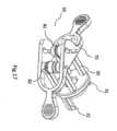
図1を参照すると、既に上で言及したように、使用時の従来技術の器具が、トロカール(6)として知られる器具ホルダの中に挿入されており、器具ホルダが、切開部を通しての患者腔の中への腹腔鏡外科器具の挿入を誘導する。トロカール(6)及びひいてはトロカール(6)の中に挿入された任意の器具が、4自由度を有する。第1の自由度が、トロカール(6)の直線カニューレ(5)の軸に沿う並進自由度(3)である。他の3つの自由度が回転自由度である。これらの他の自由度が、具体的には、カニューレ(5)に平行な軸を中心とした第1の回転自由度(4)、カニューレ(5)に対して垂直である第1の軸を中心とした第2の回転自由度(1)、及び、第2の軸を中心とした第3の回転自由度(2)であり、上記第2の軸が第1の軸に対して垂直である。With reference to FIG. 1, as already mentioned above, prior art instruments in use are inserted into an instrument holder known as a trocar (6), which guides the insertion of laparoscopic surgical instruments through an incision into a patient cavity. The trocar (6), and therefore any instrument inserted into the trocar (6), has four degrees of freedom. The first degree of freedom is a translational degree of freedom (3) along the axis of the straight cannula (5) of the trocar (6). The other three degrees of freedom are rotational degrees of freedom. These other degrees of freedom are specifically a first rotational degree of freedom (4) about an axis parallel to the cannula (5), a second rotational degree of freedom (1) about a first axis perpendicular to the cannula (5), and a third rotational degree of freedom (2) about a second axis, the second axis being perpendicular to the first axis.
図2、図3、図4、図6a、図6b、図8a、図8b、図12、及び図14を参照すると、本発明の器具が、
- 軸(U3)、第1の端部(A)、及び第2の端部(B)を有する接続組立体(201)と、
- 第2の端部(B)のところで接続組立体(201)の軸(U3)に対して入射するそれ自体の回転軸(U2’)を有するエンド・エフェクタ(301)であって、上記エンド・エフェクタ(301)が、接続組立体(201)の第2の端部(B)上に設置される、エンド・エフェクタ(301)と、
- 第1の端部(A)のところで接続組立体(201)の軸(U3)に対して入射するそれ自体の回転軸(U2)を有する操作ユニット(101)であって、上記操作ユニット(101)が、接続組立体(201)の第1の端部(A)上に設置される、操作ユニット(101)と、
- モーションを操作ユニット(101)からエンド・エフェクタ(301)に伝達するための手段(111、211、311、411、110、210、310、400、400’、310’、110’、210’、410、510、610、710、411、511、611、711、811、911、110”、210”、310”、91、92)と
を備える。 2, 3, 4, 6a, 6b, 8a, 8b, 12 and 14, the device of the present invention comprises:
a connection assembly (201) having an axis (U3 ), a first end (A) and a second end (B);
an end effector (301) having its own axis of rotation (U2 ') incident at its second end (B) relative to the axis (U3 ) of the connection assembly (201), said end effector (301) being mounted on the second end (B) of the connection assembly (201);
an operating unit (101) having its own axis of rotation (U2 ) incident at its first end (A) relative to the axis (U3 ) of the connection assembly (201), said operating unit (101) being mounted on the first end (A) of the connection assembly (201);
- means (111, 211, 311, 411, 110, 210, 310, 400, 400', 310', 110', 210', 410, 510, 610, 710, 411, 511, 611, 711, 811, 911, 110", 210", 310", 91, 92) for transmitting motion from the manipulation unit (101) to the end effector (301).
モーションを伝達するための手段(111、211、311、411、110、210、310、400、400’、310’、110’、210’、410、510、610、710、411、511、611、711、811、911、110”、210”、310”、91、92)が、少なくとも、
- 接続組立体(201)の軸(U3)と直交する平面に属し、接続組立体(201)の第1の端部(A)のところで接続組立体(201)の軸(U3)に対して入射する第1の軸(U1)を中心とした操作ユニット(101)の第1の回転運動をエンド・エフェクタ(301)に伝達するための手段(111、211、311、411、310’、110’、210’、410、510、610、710、411、511、611、711、811、911)であって、その結果、エンド・エフェクタ(301)が、接続組立体(201)の軸(U3)と直交し、接続組立体(201)の第2の端部(B)のところで接続組立体(201)の軸(U3)に対して入射する軸(U1’)を中心として回転するようになる、第1の回転運動を伝達するための手段(111、211、311、411、310’、110’、210’、410、510、610、710、411、511、611、711、811、911)と、
- それ自体の軸(U2)を中心とした操作ユニット(101)の第2の回転運動をエンド・エフェクタ(301)に伝達するための手段(110、210、310、400、400’、110”、210”、310”、91、92)であって、その結果、エンド・エフェクタ(301)が、それ自体の軸(U2’)を中心として回転するようになり、エンド・エフェクタ(301)の軸(U2’)が、操作ユニット(101)の軸(U2)に平行である、第2の回転運動を伝達するための手段(110、210、310、400、400’、110”、210”、310”、91、92)と
を備える。 a means for transmitting motion (111, 211, 311, 411, 110, 210, 310, 400, 400', 310', 110', 210', 410, 510, 610, 710, 411, 511, 611, 711, 811, 911, 110", 210", 310", 91, 92) comprising at least
- means (111, 211, 311, 411, 310', 110', 210', 410, 510, 610, 710, 411, 511, 611, 711, 811, 911) for transmitting to the end effector (301)a first rotational movement of the operating unit (101) about a first axis (U1 ) which belongs to a plane perpendicular to the axis (U3 ) of the connection assembly (201) and which is incident on the axis (U 3 ) of the connection assembly (201) at a first end (A) of the connection assembly (201), so that the end effector (301) is rotated about a first axis (U 1 ) which belongs to a plane perpendicular to the axis (U3 ) of the connection assembly (201) and which is incident on the axis (U 3) of the connection assembly (201) at a second end (B) of the connection assembly (201); means (111, 211, 311, 411, 310', 110', 210', 410, 510, 610, 710, 411, 511, 611, 711, 811, 911) for transmitting a first rotational motion, the first rotational motion being caused to rotate about an axis (U 1 ') incident on the first rotational motion;
- means (110, 210, 310, 400, 400', 110", 210", 310", 91, 92) for transmitting a second rotational movement of the operational unit (101) about its own axis (U2 ) to the end effector (301), such that the end effector (301) rotates about its own axis (U2 ' ), the axis (U2 ' ) of the end effector (301) being parallel to the axis (U2 ) of the operational unit (101).
したがって、本発明の器具は、トロカールの運動によって保証される自由度に加えて、少なくとも2つの回転自由度(θ1、θ2)を有し、ここでは、器具が、外科的介入中の使用時に挿入される必要がある。第1の回転自由度(θ1)が上述の第1の回転運動に関連し、第2の回転自由度(θ2)が第2の回転運動に関連する。器具が患者の表面(10)を通して患者腔の中に挿入されると仮定すると、器具の作業フィールドが2つの主ボリュームに分割され、第1のボリューム(11)が患者腔の外側にあり、第2のボリューム(11’)が患者腔の内側にある。操作ユニット(101)の回転(θ1、θ2)が第1のボリューム(11)に適用され、接続組立体(201)に一致するか又は接続組立体(201)内に配置される手段を通してエンド・エフェクタに伝達され、エンド・エフェクタが第2のボリューム(11’)まで回転する。したがって、接続組立体(201)が患者の表面(10)を通過する。 The inventive instrument therefore has at least two rotational degrees of freedom (θ1 , θ2 ), in addition to the degrees of freedom guaranteed by the trocar movement, in which the instrument needs to be inserted when used during a surgical intervention. The first rotational degree of freedom (θ 1 ) is associated with the above-mentioned first rotational movement, and the second rotational degree of freedom (θ2 ) is associated with the second rotational movement. Assuming that the instrument is inserted into the patient cavity through the patient's surface (10), the working field of the instrument is divided into two main volumes, the first volume (11) being outside the patient cavity and the second volume (11') being inside the patient cavity. The rotation (θ1 , θ2 ) of the operating unit (101) is applied to the first volume (11) and transmitted to the end effector through means that coincide with or are arranged in the connection assembly (201), causing the end effector to rotate to the second volume (11'). Thus, the connection assembly (201) passes through the patient's surface (10).
図1、図2、図10a、図10b、図10c、及び図11を参照すると、上に記載される2つの回転自由度(θ1、θ2)に加えて、本発明の器具が、別の回転(θ4)を操作ユニット(101)からエンド・エフェクタ(301)に伝達するのに使用され得、上記別の回転(θ4)が、接続組立体(201)の軸(U3)と直交し、接続組立体(201)の第1の端部(A)のところで接続組立体(201)の軸(U3)に対して入射する第2の軸(U4)を中心とする。この別の回転(θ4)がエンド・エフェクタ(301)に伝達され、その結果、エンド・エフェクタ(301)が、第2の軸(U4)に平行であって接続組立体(201)の第2の端部(B)のところで接続組立体(201)の軸(U3)に対して入射する軸(U4’)を中心として回転するようになる。 With reference to Figures 1, 2, 10a, 10b, 10c and 11, in addition to the two rotational degrees of freedom (θ1 ,θ2 ) described above, the instrument of the present invention can be used to transmit another rotation (θ4 ) from the operating unit (101) to the end effector (301), said another rotation (θ4 ) being centered on a second axis (U4) perpendicular to the axis (U3 ) of the connection assembly (201) and incident on the axis (U3 ) of the connection assembly (201) at the first end (A) of the connection assembly (201 ). This other rotation (θ4 ) is transmitted to the end effector (301), causing the end effector (301) to rotate about an axis (U4 ' ) that is parallel to the second axis (U4 ) and incident on the axis (U3 ) of the connection assembly (201) at the second end (B) of the connection assembly (201).
このような追加の回転(θ4)は、下記のように器具を使用して実施され得る。操作ユニット(101)自体の軸(U2)及びエンド・エフェクタ(301)自体の軸(U2’)の両方を接続組立体(201)の軸(U3)に位置合わせさせる位置から開始して、第1の軸(U1)を中心として操作ユニット(101)を回転させるのを可能にするのと同じ手段を使用することにより、操作ユニット(101)が、それ自体の軸(U2)を中心として90°回転させられ得、次いで、第2の軸(U4)を中心として回転させられ得る。したがって、第1の回転運動を操作ユニット(101)からエンド・エフェクタ(301)に伝達するのと同じ手段により、第2の軸(U4)を中心とした操作ユニット(101)の回転がエンド・エフェクタ(301)に伝達され得る。 Such an additional rotation (θ4 ) can be performed using the tool as follows: starting from a position where both its own axis (U2 ) and its own axis (U2 ′) of the operation unit (101) are aligned with the axis (U 3 ) of the connection assembly (201), the operation unit (101) can be rotated 90° around its own axis (U2 ) and then around the second axis (U4 ) by using the same means that allow the operation unit (101) to be rotated around the first axis (U1 ). Thus, the rotation of the operation unit (101) around the second axis (U4 ) can be transmitted to the end effector (301) by the same means that transmit the first rotational movement from the operation unit (101) to the end effector (301).
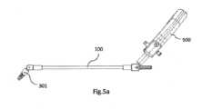
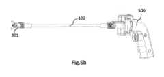
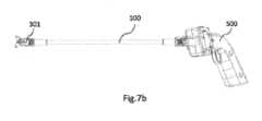
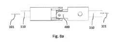
本発明の器具の第1の実施例である、図2、図3、図4、図5a、図5b、図6a、図6b、図7a、図7b、図8a、及び図8bを参照すると、接続組立体(201)が円筒形フレーム(100)を備える。第1の回転運動を伝達するための手段(111、211、311、411)が、
- 操作ユニット(101)に堅固に接続され、接続組立体(201)の第1の端部(A)に対応して位置する頂点を有する、第1の傘歯車(111)と、
- 第1の傘歯車(111)と共に第1の歯車組立体を形成する第2の傘歯車(211)であって、その結果、それ自体の軸を中心とした第1の傘歯車(111)の回転が、それ自体の軸を中心とした第2の傘歯車(211)の回転を引き起こすことになる、第2の傘歯車(211)と、
- エンド・エフェクタ(301)に堅固に接続され、接続組立体(201)の第2の端部(B)に対応する頂点を有する、第3の傘歯車(311)と、
- 第3の傘歯車(311)と共に第2の歯車組立体を形成する第4の傘歯車(411)であって、その結果、それ自体の軸を中心とした第4の傘歯車(411)の回転が、それ自体の軸を中心とした第3の傘歯車(311)の回転を引き起こすことになる、第4の傘歯車(411)と、
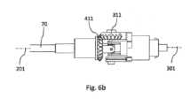
- 接続組立体(201)の軸(U3)に位置合わせされ、フレーム(100)内に収容される、中空管(70)であって、上記中空管(70)が、第2の傘歯車(211)及び第4の傘歯車(411)と協働し、その結果、それ自体の軸を中心とした第2の傘歯車(211)の回転が、それ自体の軸を中心とした第4の傘歯車(411)の回転を引き起こすことになる、中空管(70)と
を備える。 2, 3, 4, 5a, 5b, 6a, 6b, 7a, 7b, 8a and 8b, which is a first embodiment of the device of the present invention, a connection assembly (201) comprises a cylindrical frame (100). A means (111, 211, 311, 411) for transmitting a first rotational motion is
a first bevel gear (111) rigidly connected to the operating unit (101) and having an apex located corresponding to the first end (A) of the connection assembly (201);
a second bevel gear (211) forming a first gear assembly together with the first bevel gear (111), so that a rotation of the first bevel gear (111) about its own axis causes a rotation of the second bevel gear (211) about its own axis;
a third bevel gear (311) rigidly connected to the end effector (301) and having an apex corresponding to the second end (B) of the connection assembly (201);
a fourth bevel gear (411) forming a second gear assembly together with the third bevel gear (311), so that a rotation of the fourth bevel gear (411) about its own axis causes a rotation of the third bevel gear (311) about its own axis;
a hollow tube (70) aligned with the axis (U3 ) of the connection assembly (201) and housed in the frame (100), said hollow tube (70) cooperating with the second bevel gear (211) and with the fourth bevel gear (411) so that the rotation of the second bevel gear (211) about its own axis causes the rotation of the fourth bevel gear (411) about its own axis.
第2の回転運動を伝達するための手段(110、210、310、400、400’)が、
- 操作ユニット(101)に堅固に接続された第1のシャフト(110)と、
- エンド・エフェクタ(301)に堅固に接続された第2のシャフト(210)と、
- 接続組立体(201)の軸(U3)に位置合わせされた第3のシャフト(310)であって、上記第3のシャフト(310)が管(70)内に収容される、第3のシャフト(310)と、
- 接続組立体(201)の第1の端部(A)に対応して中央に配置された第1のカルダン・ジョイント(400)と、
- 接続組立体(201)の第2の端部(B)に対応して中央に配置された第2のカルダン・ジョイント(400’)と
を備える。 A means (110, 210, 310, 400, 400') for transmitting a second rotational motion
a first shaft (110) rigidly connected to the operating unit (101);
a second shaft (210) rigidly connected to the end effector (301);
a third shaft (310) aligned with the axis (U3 ) of the connection assembly (201), said third shaft (310) being housed within the tube (70);
a first Cardan joint (400) centrally located corresponding to the first end (A) of the connection assembly (201);
a second Cardan joint (400') centrally located corresponding to the second end (B) of the connection assembly (201);
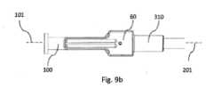
図9a及び図9bを参照すると、本発明の器具の第1の実施例が、フレーム(100)上に設置されたブレーキ・ブロック(60)をさらに備え、上記ブレーキ・ブロック(60)が、接続組立体(201)の軸(U3)に沿って第1のシャフト(110)、第3のシャフト(310)、及び第2のシャフト(210)を位置合わせするとき、接続組立体(201)の軸(U3)を中心としたフレーム(100)の意図されない回転を回避するように構成される。 Referring to Figures 9a and 9b, the first embodiment of the instrument of the present invention further comprises a brake block (60) mounted on the frame (100), the brake block (60) being configured to prevent unintended rotation of the frame (100) around the axis (U3 ) of the connection assembly (201) when aligning the first shaft (110), the third shaft (310), and the second shaft (210) along the axis (U3 ) of the connection assembly (201).
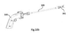
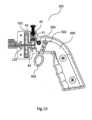
図2、図3、図4、図5a、図5b、図6a、図6b、図7a、図7b、図8a、図8b、図15、図19a、及び図19bを参照すると、本発明の第2の実施例が、第1の実施例に関連して上で言及したすべての特徴を備えるが、加えて、第2の実施例の操作ユニット(101)が、
- ハンドル(500、500’)と、
- ハンドル(500、500’)を第1のシャフト(110、110’、110”)に接続するドラム・ブレーキであって、上記ドラム・ブレーキが、
・クラッチ・パッド(41)、
・圧縮パッド(42)、
・クラッチ・パッド及び圧縮パッド(42)を接続するばね(43)、及び、
・第1のシャフト(110、110’、110”)に堅固に接続されたドラム・プーリ(44)
を備える、ドラム・ブレーキと、
- ドラム・プーリ(44)に堅固に接続されたハンドリング・リング(501、501’)であって、その結果、それ自体の軸を中心としたハンドリング・リング(501、501’)の回転が、それら自体の軸を中心としたドラム・プーリ(44)及びひいては第1のシャフト(110、110’、110”)の回転を引き起こすことになる、ハンドリング・リング(501、501”)と
を備える。 With reference to Figures 2, 3, 4, 5a, 5b, 6a, 6b, 7a, 7b, 8a, 8b, 15, 19a and 19b, a second embodiment of the present invention comprises all the features mentioned above in relation to the first embodiment, but in addition, the operating unit (101) of the second embodiment comprises:
a handle (500, 500'),
a drum brake connecting a handle (500, 500') to a first shaft (110, 110', 110"), said drum brake comprising:
Clutch pad (41),
- compression pad (42),
A spring (43) connecting the clutch pads and the compression pads (42), and
A drum pulley (44) rigidly connected to the first shaft (110, 110', 110");
A drum brake comprising:
a handling ring (501, 501') rigidly connected to the drum pulley (44), so that a rotation of the handling ring (501, 501') about its own axis causes a rotation of the drum pulley (44) and thus the first shaft (110, 110', 110") about their own axis.
図2、図3、図4、図15、図16a、図16b、図19a、及び図19bを参照すると、本発明の第3の実施例が、
- 軸(U3)を有する接続組立体(201)と、
- 接続組立体(201)の第1の端部上に設置されたエンド・エフェクタ(301)であって、上記エンド・エフェクタ(301)が、
・第1のアーム(161)、
・第2のアーム(162)、
・第1のアーム(161)に堅固に接続されたプーリ(171)、
・第2のアーム(162)に堅固に接続された第1の歯車(152)、
・第1の歯車(152)と共に歯車組立体(151、152)を形成する第2の歯車(151)であって、上記第2の歯車(151)が、プーリ(171)と同心であり、プーリ(171)に一体に接続される、第2の歯車(151)、
を備える、エンド・エフェクタ(301)と、
- 接続組立体(201)の第2の端部上に設置された操作ユニット(101)であって、上記操作ユニット(101)が、
・トリガー(502、502’)、
・トリガー(502、502’)に堅固に接続されたプーリ(503)、
・アイドル・プーリ(504)、
を備える、操作ユニット(101)と、
- 操作ユニット(101)に堅固に接続された第1のシャフトと、
- エンド・エフェクタ(301)に堅固に接続された第2のシャフトと
を備える。 Referring to Figures 2, 3, 4, 15, 16a, 16b, 19a and 19b, a third embodiment of the present invention comprises:
a connection assembly (201) having an axis (U3 ),
an end effector (301) mounted on the first end of the connection assembly (201), said end effector (301) comprising:
a first arm (161),
- a second arm (162),
a pulley (171) rigidly connected to the first arm (161);
a first gear (152) rigidly connected to a second arm (162);
a second gear (151) forming a gear assembly (151, 152) together with the first gear (152), said second gear (151) being concentric with and integrally connected to a pulley (171);
An end effector (301),
an operating unit (101) installed on the second end of the connection assembly (201), said operating unit (101) comprising:
Trigger (502, 502′),
A pulley (503) rigidly connected to the trigger (502, 502');
- Idle pulley (504),
An operation unit (101) comprising:
a first shaft rigidly connected to the operating unit (101);
a second shaft rigidly connected to the end effector (301).
エンド・エフェクタ(301)の開閉を決定する2つのアーム(161、162)の運動(α)を可能にするために、器具が、モーションを操作ユニット(101)からエンド・エフェクタ(301)に伝達するための手段を備え、モーションを伝達するための手段が、操作ユニット(101)のプーリ(503)をエンド・エフェクタ(301)のプーリ(171)に接続する図に示されないケーブルを備え、上記ケーブルが、操作ユニット(101)のプーリ(503)の周りに巻き付けられる前に、アイドル・プーリ(504)によって2つの部分に分割される。To enable a movement (α) of the two arms (161, 162) that determines the opening and closing of the end effector (301), the instrument comprises means for transmitting a motion from the operating unit (101) to the end effector (301), the means for transmitting a motion comprising a cable, not shown in the figure, connecting the pulley (503) of the operating unit (101) to the pulley (171) of the end effector (301), said cable being split into two parts by an idle pulley (504) before being wound around the pulley (503) of the operating unit (101).
上記ケーブルが、具体的には、第1のシャフトに堅固に接続された第1の端部及び第2のシャフトに堅固に接続された第2の端部を有する接続組立体(201)のシースの中に挿入される。The cable is inserted into the sheath of a connection assembly (201) having a first end firmly connected to a first shaft and a second end firmly connected to a second shaft.
本記述では、「シース」という単語は、「ケーブルの上にある可撓性の保護用外側被覆物」を意味する。言い換えると、シース及びケーブルが、自転車の変速装置のためのシース及びワイヤに類似する。In this description, the word "sheath" means "a flexible, protective outer covering over a cable." In other words, the sheath and cable are similar to the sheath and wires for a bicycle transmission.
図2、図3、図4、図5a、図5b、図6a、図6b、図7a、図7b、図8a、図8b、図15、図16a、及び図16bを参照すると、本発明の第4の実施例が、
- 軸(U3)、第1の端部(A)、及び第2の端部(B)を有する接続組立体(201)と、
- 第2の端部(B)のところで接続組立体(201)の軸(U3)に対して入射するそれ自体の回転軸(U2’)を有するエンド・エフェクタ(301)であって、上記エンド・エフェクタ(301)が接続組立体(201)の第2の端部(B)上に設置され、上記エンド・エフェクタ(301)が、
・第1のアーム(161)、
・第2のアーム(162)、
・第1のアーム(161)に堅固に接続されたプーリ(171)、
・第2のアーム(162)に堅固に接続された第1の歯車(152)、
・第1の歯車(152)と共に歯車組立体(151、152)を形成する第2の歯車(151)であって、上記第2の歯車(151)が、プーリ(171)と同心であり、プーリ(171)に一体に接続される、第2の歯車(151)
を備える、エンド・エフェクタ(301)と、
- 第1の端部(A)のところで接続組立体(201)の軸(U3)に対して入射するそれ自体の回転軸(U2)を有する操作ユニット(101)であって、上記操作ユニット(101)が接続組立体(201)の第1の端部(A)上に設置され、上記操作ユニット(101)が、
・トリガー(502、502’)、
・トリガー(502、502’)に堅固に接続されたプーリ(503)、
・アイドル・プーリ(504)、
を備える、操作ユニット(101)と、
- 接続組立体(201)の軸(U3)と直交する平面に属し、接続組立体(201)の第1の端部(A)のところで接続組立体(201)の軸(U3)に対して入射する第1の軸(U1)を中心とした操作ユニット(101)の第1の回転運動をエンド・エフェクタ(301)に伝達するための手段(111、211、311、411、310’、110’、210’、410、510、610、710、411、511、611、711、811、911)であって、その結果、エンド・エフェクタ(301)が、接続組立体(201)の軸(U3)と直交し、接続組立体(201)の第2の端部(B)のところで接続組立体(201)の軸(U3)に対して入射する軸(U1’)を中心として回転するようになる、第1の回転運動を伝達するための手段(111、211、311、411、310’、110’、210’、410、510、610、710、411、511、611、711、811、911)と、
- それ自体の軸(U2)を中心とした操作ユニット(101)の第2の回転運動をエンド・エフェクタ(301)に伝達するための手段(110、210、310、400、400’、110”、210”、310”、91、92)であって、その結果、エンド・エフェクタ(301)が、それ自体の軸(U2’)を中心として回転するようになる、第2の回転運動を伝達するための手段(110、210、310、400、400’、110”、210”、310”、91、92)と
を備える。 Referring to Figures 2, 3, 4, 5a, 5b, 6a, 6b, 7a, 7b, 8a, 8b, 15, 16a and 16b, a fourth embodiment of the present invention comprises:
a connection assembly (201) having an axis (U3 ), a first end (A) and a second end (B);
an end effector (301) having its own axis of rotation (U2 ') incident at its second end (B) relative to the axis (U3 ) of the connection assembly (201), said end effector (301) being placed on the second end (B) of the connection assembly (201), said end effector (301) being:
a first arm (161),
- a second arm (162),
a pulley (171) rigidly connected to the first arm (161);
a first gear (152) rigidly connected to a second arm (162);
a second gear (151) forming a gear assembly (151, 152) together with the first gear (152), said second gear (151) being concentric with and integrally connected to the pulley (171);
An end effector (301),
an operating unit (101) having its own axis of rotation (U2 ) incident at its first end (A) relative to the axis (U3 ) of the connection assembly (201), said operating unit (101) being installed on the first end (A) of the connection assembly (201), said operating unit (101) comprising:
Trigger (502, 502′),
A pulley (503) rigidly connected to the trigger (502, 502');
- Idle pulley (504),
An operation unit (101) comprising:
- means (111, 211, 311, 411, 310', 110', 210', 410, 510, 610, 710, 411, 511, 611, 711, 811, 911) for transmitting to the end effector (301)a first rotational movement of the operating unit (101) about a first axis (U1 ) which belongs to a plane perpendicular to the axis (U3 ) of the connection assembly (201) and which is incident on the axis (U 3 ) of the connection assembly (201) at a first end (A) of the connection assembly (201), so that the end effector (301) is rotated about a first axis (U 1 ) which belongs to a plane perpendicular to the axis (U3 ) of the connection assembly (201) and which is incident on the axis (U 3) of the connection assembly (201) at a second end (B) of the connection assembly (201); means (111, 211, 311, 411, 310', 110', 210', 410, 510, 610, 710, 411, 511, 611, 711, 811, 911) for transmitting a first rotational motion, the first rotational motion being caused to rotate about an axis (U 1 ') incident on the first rotational motion;
- means (110, 210, 310, 400, 400', 110", 210", 310", 91, 92) for transmitting a second rotational movement of the operating unit (101) about its own axis (U2 ) to the end effector (301), so that the end effector (301) rotates about its own axis (U2 ' ).
2、3、4、5a、5b、6a、6b、7a、7b、8a、8b、16a、及び16bを参照すると、接続組立体(201)が円筒形フレーム(100)を備える。第1の回転運動を伝達するための手段(111、211、311、411)が、
- 操作ユニット(101)に堅固に接続され、接続組立体(201)の第1の端部(A)に対応して位置する頂点を有する、第1の傘歯車(111)と、
- 第1の傘歯車(111)と共に第1の歯車組立体を形成する第2の傘歯車(211)であって、その結果、それ自体の軸を中心とした第1の傘歯車(111)の回転が、それ自体の軸を中心とした第2の傘歯車(211)の回転を引き起こすことになる、第2の傘歯車(211)と、
- エンド・エフェクタ(301)に堅固に接続され、接続組立体(201)の第2の端部(B)に対応する頂点を有する、第3の傘歯車(311)と、
- 第3の傘歯車(311)と共に第2の歯車組立体を形成する第4の傘歯車(411)であって、その結果、それ自体の軸を中心とした第4の傘歯車(411)の回転が、それ自体の軸を中心とした第3の傘歯車(311)の回転を引き起こすことになる、第4の傘歯車(411)と、
- 接続組立体(201)の接続組立体(201)の軸(U3)に位置合わせされ、フレーム(100)内に収容される、中空管(70)であって、上記中空管(70)が、第2の傘歯車(211)及び第4の傘歯車(411)と協働し、その結果、それ自体の軸を中心とした第2の傘歯車(211)の回転が、それ自体の軸を中心とした第4の傘歯車(411)の回転を引き起こすことになる、中空管(70)と
を備える。 2, 3, 4, 5a, 5b, 6a, 6b, 7a, 7b, 8a, 8b, 16a and 16b, a connection assembly (201) comprises a cylindrical frame (100). A means (111, 211, 311, 411) for transmitting a first rotational motion is
a first bevel gear (111) rigidly connected to the operating unit (101) and having an apex located corresponding to the first end (A) of the connection assembly (201);
a second bevel gear (211) forming a first gear assembly together with the first bevel gear (111), so that a rotation of the first bevel gear (111) about its own axis causes a rotation of the second bevel gear (211) about its own axis;
a third bevel gear (311) rigidly connected to the end effector (301) and having an apex corresponding to the second end (B) of the connection assembly (201);
a fourth bevel gear (411) forming a second gear assembly together with the third bevel gear (311), so that a rotation of the fourth bevel gear (411) about its own axis causes a rotation of the third bevel gear (311) about its own axis;
a hollow tube (70) aligned with the axis (U3 ) of the connection assembly (201) and housed in the frame (100), said hollow tube (70) cooperating with the second bevel gear (211) and the fourth bevel gear (411) so that the rotation of the second bevel gear (211) about its own axis causes the rotation of the fourth bevel gear (411) about its own axis.
第2の回転運動を伝達するための手段(110、210、310、400、400’)が、
- 操作ユニット(101)に堅固に接続された第1のシャフト(110)と、
- エンド・エフェクタ(301)に堅固に接続された第2のシャフト(210)と、
- 接続組立体(201)の軸(U3)に位置合わせされた第3のシャフト(310)であって、上記第3のシャフト(310)が管(70)内に収容される、第3のシャフト(310)と、
- 接続組立体(201)の第1の端部(A)に対応して中央に配置された第1のカルダン・ジョイント(400)と、
- 接続組立体(201)の第2の端部(B)に対応して中央に配置された第2のカルダン・ジョイント(400’)と
を備える。 A means (110, 210, 310, 400, 400') for transmitting a second rotational motion
a first shaft (110) rigidly connected to the operating unit (101);
a second shaft (210) rigidly connected to the end effector (301);
a third shaft (310) aligned with the axis (U3 ) of the connection assembly (201), said third shaft (310) being housed within the tube (70);
a first Cardan joint (400) centrally located corresponding to the first end (A) of the connection assembly (201);
a second Cardan joint (400') centrally located corresponding to the second end (B) of the connection assembly (201);
エンド・エフェクタ(301)の開閉を決定する2つのアーム(161、162)の運動(α)を可能にするために、器具が、モーションを操作ユニット(101)からエンド・エフェクタ(301)に伝達するための手段を備え、モーションを伝達するための手段が、操作ユニット(101)のプーリ(503)をエンド・エフェクタ(301)のプーリ(171)に接続する図に示されないケーブルを備え、上記ケーブルが、操作ユニット(101)のプーリ(503)の周りに巻き付けられる前に、アイドル・プーリ(504)によって2つの部分に分割される。上記ケーブルが、具体的には、第1のシャフトに堅固に接続された第1の端部及び第2のシャフトに堅固に接続された第2の端部を有する接続組立体(201)のシースの中に挿入される。To allow a movement (α) of the two arms (161, 162) that determines the opening and closing of the end effector (301), the instrument comprises a means for transmitting a motion from the operating unit (101) to the end effector (301), the means for transmitting a motion comprising a cable, not shown in the figure, that connects the pulley (503) of the operating unit (101) to the pulley (171) of the end effector (301), said cable being split into two parts by an idle pulley (504) before being wound around the pulley (503) of the operating unit (101). The said cable is inserted into the sheath of the connection assembly (201) specifically having a first end rigidly connected to a first shaft and a second end rigidly connected to a second shaft.
さらに、図9a及び図9bを参照すると、本発明の器具の第4の実施例が、フレーム(100)上に設置されたブレーキ・ブロック(60)をさらに備え、上記ブレーキ・ブロック(60)が、接続組立体(201)の軸(U3)に沿って第1のシャフト(110)、第3のシャフト(310)、及び第2のシャフト(210)を位置合わせするとき、接続組立体(201)の軸(U3)を中心としたフレーム(100)の意図されない回転を回避するように構成される。 Further, referring to Figures 9a and 9b, a fourth embodiment of the instrument of the present invention further comprises a brake block (60) mounted on the frame (100), the brake block (60) being configured to prevent unintended rotation of the frame (100) around the axis (U3 ) of the connection assembly (201) when aligning the first shaft (110), the third shaft (310), and the second shaft (210) along the axis (U3 ) of the connection assembly (201).
図2、図3、図4、図5a、図5b、図6a、図6b、図7a、図7b、図8a、図8b、図15、図16a、図16b、図19a、及び図19bを参照すると、本発明の第5の実施例が第4の実施例に関連して上で言及したすべての特徴を備えるが、加えて、第4の実施例の操作ユニット(101)が、
- ハンドル(500、500’)と、
- ハンドル(500、500’)を第1のシャフト(110、110’、110”)に接続するドラム・ブレーキであって、上記ドラム・ブレーキが、
・クラッチ・パッド(41)、
・圧縮パッド(42)、
・クラッチ・パッド及び圧縮パッド(42)を接続するばね(43)、及び、
・第1のシャフト(110、110’、110”)に堅固に接続されたドラム・プーリ(44)、
を備える、ドラム・ブレーキと、
- ドラム・プーリ(44)に堅固に接続されたハンドリング・リング(501、501’)であって、その結果、それ自体の軸を中心としたハンドリング・リング(501、501’)の回転が、それら自体の軸を中心としたドラム・プーリ(44)及びひいては第1のシャフト(110、110’、110”)の回転を引き起こすことになる、ハンドリング・リング(501、501”)と
を備える。 With reference to Figures 2, 3, 4, 5a, 5b, 6a, 6b, 7a, 7b, 8a, 8b, 15, 16a, 16b, 19a and 19b, a fifth embodiment of the present invention comprises all the features mentioned above in relation to the fourth embodiment, but in addition, the operating unit (101) of the fourth embodiment:
a handle (500, 500'),
a drum brake connecting a handle (500, 500') to a first shaft (110, 110', 110"), said drum brake comprising:
Clutch pad (41),
- compression pad (42),
A spring (43) connecting the clutch pads and the compression pads (42), and
a drum pulley (44) rigidly connected to the first shaft (110, 110', 110");
A drum brake comprising:
a handling ring (501, 501') rigidly connected to the drum pulley (44), so that a rotation of the handling ring (501, 501') about its own axis causes a rotation of the drum pulley (44) and thus the first shaft (110, 110', 110") about their own axis.
本発明の器具の第6の実施例の図2、図12、図13、及び図14を参照すると、第1の回転運動を伝達するための手段(310’、110’、210’、410、510、610、710、411、511、611、711、811、911)が、
- 操作ユニット(101)に堅固に接続された第1のシャフト(110’)と、
- エンド・エフェクタ(301)に堅固に接続された第2のシャフト(210’)と、
- 接続組立体(201)の軸(U3)に位置合わせされた第3のシャフト(310’)であって、第3のシャフト(310’)の第1の端部が、接続組立体(201)の第1の端部(A)に一致し、第3のシャフト(310’)の第2の端部が、接続組立体(201)の第2の端部(B)に一致する、第3のシャフト(310’)と、
- 第3のシャフト(310’)の第1の端部(A)に一致する回転中心を有する第1の湾曲ヒンジ(411)により第3のシャフト(310’)に接続された第4のシャフト(410)と、
- 第3のシャフト(310’)の第2の端部(B)に一致する回転中心を有する第2の湾曲ヒンジ(511)により第3のシャフト(310’)に接続された第5のシャフト(510)と、
- 第3の湾曲ヒンジ(611)により第4のシャフト(410)の第1の部分(H1A)に接続され、第4の湾曲ヒンジ(711)により第5のシャフト(510)の第1の部分(H4B)に接続された第6のシャフト(610)と、
- 第5の湾曲ヒンジ(811)により第4のシャフト(410)の第2の部分(AH2)に接続され、第6の湾曲ヒンジ(911)により第5のシャフト(510)の第2の部分(BH3)に接続された第7のシャフト(710)と
を備える。 2, 12, 13 and 14 of a sixth embodiment of the device of the present invention, the means for transmitting a first rotational motion (310', 110', 210', 410, 510, 610, 710, 411, 511, 611, 711, 811, 911) comprises:
a first shaft (110') rigidly connected to the operating unit (101);
a second shaft (210') rigidly connected to the end effector (301);
a third shaft (310') aligned with the axis (U3 ) of the connection assembly (201), a first end of the third shaft (310') coinciding with the first end (A) of the connection assembly (201) and a second end of the third shaft (310') coinciding with the second end (B) of the connection assembly (201);
a fourth shaft (410) connected to the third shaft (310') by a first curved hinge (411) having a centre of rotation coinciding with the first end (A) of the third shaft (310');
a fifth shaft (510) connected to the third shaft (310') by a second curved hinge (511) having a centre of rotation coinciding with the second end (B) of the third shaft (310');
a sixth shaft (610) connected by a third curved hinge (611) to a first portion (H1 A) of the fourth shaft (410) and by a fourth curved hinge (711) to a first portion (H4 B) of the fifth shaft (510);
a seventh shaft (710) connected to the second part (AH2 ) of the fourth shaft (410) by a fifth curved hinge (811) and to the second part (BH3 ) of the fifth shaft (510) by a sixth curved hinge (911).
第1の湾曲ヒンジ(411)、第2の湾曲ヒンジ(511)、第3の湾曲ヒンジ(611)、第4の湾曲ヒンジ(711)、第5の湾曲ヒンジ(811)、及び第6の湾曲ヒンジ(911)が、限定しないが、好適には、円形湾曲ヒンジである。The first curved hinge (411), the second curved hinge (511), the third curved hinge (611), the fourth curved hinge (711), the fifth curved hinge (811), and the sixth curved hinge (911) are preferably, but not limited to, circular curved hinges.
第2の回転運動を伝達するための手段(110”、210”、310”、91、92)が、代わりに、
- 操作ユニット(101)に堅固に接続された第1のシャフト(110”)と、
- エンド・エフェクタ(301)に堅固に接続された第2のシャフト(210”)と、
- 接続組立体(201)の軸(U3)に位置合わせされた第3のシャフト(310”)と、
- 第1のシャフト(110”)の第1の端部に接続された第1の端部(A’)及び第3のシャフト(310”)の第1の端部に接続された第2の端部(A”)を有する第1のトルク・コイル(91)であって、接続組立体(201)の第1の端部(A)が、第1のトルク・コイル(91)の第1の端部(A’)と第2の端部(A”)との間に含まれる、第1のトルク・コイル(91)と、
- 第3のシャフト(310”)の第2の端部に接続された第1の端部(B’)及び第2のシャフト(210”)の第1の端部に接続された第2の端部(B”)を有する第2のトルク・コイル(92)であって、接続組立体(201)の第2の端部(B)が、第2のトルク・コイルの第1の端部(B’)と第2の端部(B”)との間に含まれる、第2のトルク・コイル(92)と
を備える。 The means for transmitting a second rotational motion (110", 210", 310", 91, 92) may alternatively be
a first shaft (110″) rigidly connected to the operating unit (101);
a second shaft (210") rigidly connected to the end effector (301);
a third shaft (310") aligned with the axis (U3 ) of the connection assembly (201);
a first torque coil (91) having a first end (A') connected to a first end of the first shaft (110") and a second end (A") connected to a first end of the third shaft (310"), the first end (A) of the connection assembly (201) being included between the first end (A') and the second end (A") of the first torque coil (91);
a second torque coil (92) having a first end (B') connected to the second end of the third shaft (310") and a second end (B") connected to the first end of the second shaft (210"), the second end (B) of the connection assembly (201) being included between the first end (B') and the second end (B") of the second torque coil.
エンド・エフェクタの開閉を実施するために、第2のトルク・コイル(92)が、それ自体の長手方向軸に沿う第2のトルク・コイル(92)の並進運動(S)を変換するための手段(900)により、エンド・エフェクタ(301)に接続され、エンド・エフェクタの2つのアームの開閉の運動(α)において、それ自体の長手方向軸に沿う第1のトルク・コイル(91)の並進運動の、第3のシャフト(310”)による、伝達により、その長手方向軸に沿う第2のトルク・コイル(92)の並進運動(S)が引き起こされる。第1のトルク・コイル(91)及び第2のトルク・コイル(92)が、それぞれ、第1のシース(91’)及び第2のシース(92’)の内部に挿入され得る。第1のシャフト(110”)が第1の中空管(800)の内部に収容され、第2のシャフト(210”)が第2の中空管(802)の内部に収容され、第3のシャフト(310”)が第3の中空管(801)の内部に収容される。第1のシース(91’)が、第1の中空管(800)に堅固に接続された第1の端部、及び、第3の中空管(801)に堅固に接続された第2の端部を有する。第2のシース(92’)が、第3の中空管(801)に堅固に接続された第1の端部、及び、第2の中空管(802)に堅固に接続された第2の端部を有する。To perform the opening and closing of the end effector, the second torque coil (92) is connected to the end effector (301) by a means (900) for converting the translational movement (S) of the second torque coil (92) along its own longitudinal axis, and the translational movement (α) of the first torque coil (91) along its own longitudinal axis is converted by the third shaft (310″) into the translational movement (α) of the first torque coil (91) along its own longitudinal axis. A translational movement (S) of the second torque coil (92) is induced such that the first torque coil (91) and the second torque coil (92) are inserted into the first sheath (91') and the second sheath (92'), respectively. The first shaft (110") is housed inside the first hollow tube (800), the second shaft (210") is housed inside the second hollow tube (802), and the third shaft (310") is housed inside the third hollow tube (801). The first sheath (91') has a first end rigidly connected to the first hollow tube (800) and a second end rigidly connected to the third hollow tube (801). The second sheath (92') has a first end that is rigidly connected to the third hollow tube (801) and a second end that is rigidly connected to the second hollow tube (802).
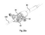
図2、図17、図18a、図18bを参照すると、本発明の第7の実施例が、
- 軸(U3)、第1の端部(A)、及び第2の端部(B)を有する接続組立体(201)であって、上記接続組立体がフレーム(100)を備える、接続組立体(201)と、
- 第2の端部(B)のところで接続組立体(201)の軸(U3)に対して入射するそれ自体の回転軸(U2’)を有するエンド・エフェクタ(301)であって、上記エンド・エフェクタ(301)が、接続組立体(201)の第2の端部(B)上に設置される、エンド・エフェクタ(301)と、
- 第1の端部(A)のところで接続組立体(201)の軸(U3)に対して入射するそれ自体の回転軸(U2)を有する操作ユニット(101)であって、上記操作ユニット(101)が、接続組立体(201)の第1の端部(A)上に設置される、操作ユニット(101)と、
- 少なくとも、それ自体の軸(U2)を中心とした操作ユニット(101)の回転運動をエンド・エフェクタ(301)に伝達するための手段であって、その結果、エンド・エフェクタ(301)が、それ自体の軸(U2’)を中心として回転するようになり、エンド・エフェクタ(301)の軸(U2’)が、操作ユニット(101)の軸(U2)に平行である、少なくとも回転運動を伝達するための手段と、
- 接続組立体(201)の軸(U3)を中心としたフレーム(100)の意図されない回転を回避するように構成された、フレーム(100)上に設置された阻止デバイス(50)であって、上記阻止デバイス(50)が、
・デバイス(50)を器具ホルダ(80)に結合するための手段(31、32)を備える支持構造(30)であって、器具が器具ホルダ(80)と協働し、上記器具ホルダ(80)が、上記腹腔鏡外科器具を切開部を通して患者腔の中に少なくとも部分的に挿入するように構成される、支持構造(30)、
・2つの円錐台ロール(81、82)であって、フレーム(100”)が2つの円錐台ロール(81、82)の間に配置される、2つの円錐台ロール(81、82)、
・2つの円錐台ロール(81、82)をフレーム(100)に接触させない第1の位置から、2つの円錐台ロール(81、82)をフレーム(100)に接触させて摩擦により接続組立体(201)の軸(U3)を中心としたフレーム(100)の回転を防止する第2の位置まで、2つの円錐台ロール(81、82)を並進移動させるのを可能にするように構成されたレバー(70)であって、接続組立体(201)の軸(U3)に沿うフレーム(100)の並進移動が可能状態で維持される、レバー(70)
を備える、阻止デバイス(50)と
を備える。 Referring to Figures 2, 17, 18a and 18b, a seventh embodiment of the present invention comprises:
a connection assembly (201) having an axis (U3 ), a first end (A) and a second end (B), said connection assembly comprising a frame (100);
an end effector (301) having its own axis of rotation (U2 ') incident at its second end (B) relative to the axis (U3 ) of the connection assembly (201), said end effector (301) being mounted on the second end (B) of the connection assembly (201);
an operating unit (101) having its own axis of rotation (U2 ) incident at its first end (A) relative to the axis (U3 ) of the connection assembly (201), said operating unit (101) being mounted on the first end (A) of the connection assembly (201);
- means for transmitting at least a rotational movement of the operating unit (101) about its own axis (U2 ) to the end effector (301), so that the end effector (301) rotates about its own axis (U2' ), the axis (U2' ) of the end effector (301) being parallel to the axis (U2 ) of the operating unit (101);
a blocking device (50) mounted on the frame (100) and configured to prevent unintended rotation of the frame (100) about the axis (U3 ) of the connection assembly (201), said blocking device (50) comprising:
a support structure (30) comprising means (31, 32) for coupling the device (50) to an instrument holder (80), the instrument cooperating with said instrument holder (80), said instrument holder (80) being configured for at least partially inserting said laparoscopic surgical instrument through an incision into a patient cavity;
- two truncated cone rolls (81, 82) with a frame (100'') disposed between the two truncated cone rolls (81, 82);
a lever (70) configured to allow translation of the two frusto-conical rolls (81, 82) from a first position in which they are not in contact with the frame (100) to a second position in which they are in contact with the frame (100) and prevent rotation of the frame (100) about the axis (U3 ) of the connection assembly (201) by friction, the lever (70) being maintained in a state in which translation of the frame (100) along the axis (U3 ) of the connection assembly (201) is possible;
and a blocking device (50).
図2、図2、図3、図4、図5a、図5b、図6a、図6b、図7a、図7b、図8a、図8b、図17、図18a、及び図18bを参照すると、本発明の器具の第8の実施例が、
- 軸(U3)を有する接続組立体(201)であって、上記接続組立体(201)がフレーム(100)を備える、接続組立体(201)と、
- 第2の端部(B)のところで接続組立体(201)の軸(U3)に対して入射するそれ自体の回転軸(U2’)を有するエンド・エフェクタ(301)であって、上記エンド・エフェクタ(301)が、接続組立体(201)の第2の端部(B)上に設置される、エンド・エフェクタ(301)と、
- 第1の端部(A)のところで接続組立体(201)の軸(U3)に対して入射するそれ自体の回転軸(U2)を有する操作ユニット(101)であって、上記操作ユニット(101)が、接続組立体(201)の第1の端部(A)上に設置される、操作ユニット(101)と、
- 接続組立体(201)の軸(U3)を中心としたフレーム(100)の意図されない回転を回避するように構成された、フレーム(100)上に設置された阻止デバイス(50)であって、上記阻止デバイス(50)が、
・デバイス(50)を器具ホルダ(80)に結合するための手段(31、32)を備える支持構造(30)であって、器具が器具ホルダ(80)と協働することができ、上記器具ホルダ(80)が、上記腹腔鏡外科器具を切開部を通して患者腔の中に少なくとも部分的に挿入するように構成される、支持構造(30)、
・2つの円錐台ロール(81、82)であって、フレーム(100”)が2つの円錐台ロール(81、82)の間に配置される、2つの円錐台ロール(81、82)、
・2つの円錐台ロール(81、82)をフレーム(100)に接触させない第1の位置から、2つの円錐台ロール(81、82)をフレーム(100)に接触させて摩擦により接続組立体(201)の軸(U3)を中心としたフレーム(100)の回転を防止する第2の位置まで、2つの円錐台ロール(81、82)を並進移動させるのを可能にするように構成されたレバー(70)であって、接続組立体(201)の軸(U3)に沿うフレーム(100)の並進移動が可能状態で維持される、レバー(70)、
備える、阻止デバイス(50)と、
- 接続組立体(201)の軸(U3)と直交する平面に属し、接続組立体(201)の第1の端部(A)のところで接続組立体(201)の軸(U3)に対して入射する第1の軸(U1)を中心とした操作ユニット(101)の第1の回転運動をエンド・エフェクタ(301)に伝達するための手段(111、211、311、411、310’、110’、210’、410、510、610、710、411、511、611、711、811、911)であって、その結果、エンド・エフェクタ(301)が、接続組立体(201)の軸(U3)と直交し、接続組立体(201)の第2の端部(B)のところで接続組立体(201)の軸(U3)に対して入射する軸(U1’)を中心として回転するようになる、第1の回転運動を伝達するための手段(111、211、311、411、310’、110’、210’、410、510、610、710、411、511、611、711、811、911)と、
- それ自体の軸(U2)を中心とした操作ユニット(101)の第2の回転運動をエンド・エフェクタ(301)に伝達するための手段(110、210、310、400、400’、110”、210”、310”、91、92)であって、その結果、エンド・エフェクタ(301)が、それ自体の軸(U2’)を中心として回転するようになり、エンド・エフェクタ(301)の軸(U2’)が、操作ユニット(101)の軸(U2)に平行である、第2の回転運動を伝達するための手段(110、210、310、400、400’、110”、210”、310”、91、92)と
を備える。 2, 2, 3, 4, 5a, 5b, 6a, 6b, 7a, 7b, 8a, 8b, 17, 18a and 18b, an eighth embodiment of the device of the present invention comprises:
a connection assembly (201) having an axis (U3 ), said connection assembly (201) comprising a frame (100);
an end effector (301) having its own axis of rotation (U2 ') incident at its second end (B) relative to the axis (U3 ) of the connection assembly (201), said end effector (301) being mounted on the second end (B) of the connection assembly (201);
an operating unit (101) having its own axis of rotation (U2 ) incident at its first end (A) relative to the axis (U3 ) of the connection assembly (201), said operating unit (101) being mounted on the first end (A) of the connection assembly (201);
a blocking device (50) mounted on the frame (100) and configured to prevent unintended rotation of the frame (100) about the axis (U3 ) of the connection assembly (201), said blocking device (50) comprising:
a support structure (30) comprising means (31, 32) for coupling the device (50) to an instrument holder (80), with which an instrument can cooperate, said instrument holder (80) being configured for at least partially inserting said laparoscopic surgical instrument through an incision into a patient cavity;
- two truncated cone rolls (81, 82) with a frame (100'') disposed between the two truncated cone rolls (81, 82);
a lever (70) configured to allow translation of the two frusto-conical rolls (81, 82) from a first position in which they are not in contact with the frame (100) to a second position in which they are in contact with the frame (100) and prevent rotation of the frame (100) about the axis (U3 ) of the connection assembly (201) by friction, the lever (70) being maintained in a state in which translation of the frame (100) along the axis (U3 ) of the connection assembly (201) is possible;
A blocking device (50),
- means (111, 211, 311, 411, 310', 110', 210', 410, 510, 610, 710, 411, 511, 611, 711, 811, 911) for transmitting to the end effector (301)a first rotational movement of the operating unit (101) about a first axis (U1 ) which belongs to a plane perpendicular to the axis (U3 ) of the connection assembly (201) and which is incident on the axis (U 3 ) of the connection assembly (201) at a first end (A) of the connection assembly (201), so that the end effector (301) is rotated about a first axis (U 1 ) which belongs to a plane perpendicular to the axis (U3 ) of the connection assembly (201) and which is incident on the axis (U 3) of the connection assembly (201) at a second end (B) of the connection assembly (201); means (111, 211, 311, 411, 310', 110', 210', 410, 510, 610, 710, 411, 511, 611, 711, 811, 911) for transmitting a first rotational motion, the first rotational motion being caused to rotate about an axis (U 1 ') incident on the first rotational motion;
- means (110, 210, 310, 400, 400', 110", 210", 310", 91, 92) for transmitting a second rotational movement of the operational unit (101) about its own axis (U2 ) to the end effector (301), such that the end effector (301) rotates about its own axis (U2 ' ), the axis (U2 ' ) of the end effector (301) being parallel to the axis (U2 ) of the operational unit (101).
接続組立体(201)が円筒形フレーム(100)を備える。第1の回転運動を伝達するための手段(111、211、311、411)が、
- 操作ユニット(101)に堅固に接続され、接続組立体(201)の第1の端部(A)に対応して位置する頂点を有する、第1の傘歯車(111)と、
- 第1の傘歯車(111)と共に第1の歯車組立体を形成する第2の傘歯車(211)であって、その結果、それ自体の軸を中心とした第1の傘歯車(111)の回転が、それ自体の軸を中心とした第2の傘歯車(211)の回転を引き起こすことになる、第2の傘歯車(211)と、
- エンド・エフェクタ(301)に堅固に接続され、接続組立体(201)の第2の端部(B)に対応する頂点を有する、第3の傘歯車(311)と、
- 第3の傘歯車(311)と共に第2の歯車組立体を形成する第4の傘歯車(411)であって、その結果、それ自体の軸を中心とした第4の傘歯車(411)の回転が、それ自体の軸を中心とした第3の傘歯車(311)の回転を引き起こすことになる、第4の傘歯車(411)と、
- 接続組立体(201)の軸(U3)に位置合わせされ、フレーム(100)内に収容される、中空管(70)であって、上記管(70)が、第2の傘歯車(211)及び第4の傘歯車(411)と協働し、その結果、それ自体の軸を中心とした第2の傘歯車(211)の回転が、それ自体の軸を中心とした第4の傘歯車(411)の回転を引き起こすことになる、中空管(70)と
を備える。 The connection assembly (201) comprises a cylindrical frame (100). The means (111, 211, 311, 411) for transmitting a first rotational motion comprises:
a first bevel gear (111) rigidly connected to the operating unit (101) and having an apex located corresponding to the first end (A) of the connection assembly (201);
a second bevel gear (211) forming a first gear assembly together with the first bevel gear (111), so that a rotation of the first bevel gear (111) about its own axis causes a rotation of the second bevel gear (211) about its own axis;
a third bevel gear (311) rigidly connected to the end effector (301) and having an apex corresponding to the second end (B) of the connection assembly (201);
a fourth bevel gear (411) forming a second gear assembly together with the third bevel gear (311), so that a rotation of the fourth bevel gear (411) about its own axis causes a rotation of the third bevel gear (311) about its own axis;
a hollow tube (70) aligned with the axis (U3 ) of the connection assembly (201) and housed in the frame (100), said tube (70) cooperating with the second bevel gear (211) and with the fourth bevel gear (411) so that the rotation of the second bevel gear (211) about its own axis causes the rotation of the fourth bevel gear (411) about its own axis.
第2の回転運動を伝達するための手段(110、210、310、400、400’)が、
- 操作ユニット(101)に堅固に接続された第1のシャフト(110)と、
- エンド・エフェクタ(301)に堅固に接続された第2のシャフト(210)と、
- 接続組立体(201)の軸(U3)に位置合わせされた第3のシャフト(310)であって、上記第3のシャフト(310)が管(70)内に収容される、第3のシャフト(310)と、
- 接続組立体(201)の第1の端部(A)に対応して中央に配置された第1のカルダン・ジョイント(400)と、
- 接続組立体(201)の第2の端部(B)に対応して中央に配置された第2のカルダン・ジョイント(400’)と
を備える。 A means (110, 210, 310, 400, 400') for transmitting a second rotational motion
a first shaft (110) rigidly connected to the operating unit (101);
a second shaft (210) rigidly connected to the end effector (301);
a third shaft (310) aligned with the axis (U3 ) of the connection assembly (201), said third shaft (310) being housed within the tube (70);
a first Cardan joint (400) centrally located corresponding to the first end (A) of the connection assembly (201);
a second Cardan joint (400') centrally located corresponding to the second end (B) of the connection assembly (201);
さらに、図9a及び図9bを参照すると、本発明の器具の第8の実施例が、フレーム(100)上に設置されたブレーキ・ブロック(60)をさらに備え、上記ブレーキ・ブロック(60)が、接続組立体の軸(U3)に沿って第1のシャフト(110)、第3のシャフト(310)、及び第2のシャフト(210)を位置合わせするとき、接続組立体(201)の軸(U3)を中心としたフレーム(100)の意図されない回転を回避するように構成される。 Further, referring to Figures 9a and 9b, an eighth embodiment of the instrument of the present invention further comprises a brake block (60) mounted on the frame (100), the brake block (60) being configured to prevent unintended rotation of the frame (100) about the axis (U3 ) of the connection assembly (201) when aligning the first shaft (110), the third shaft (310), and the second shaft (210) along the axis (U3 ) of the connection assembly.
図2、図3、図4、図5a、図5b、図6a、図6b、図7a、図7b、図8a、図8b、図15、図17、図18a、図18b、図19a、及び図19bを参照すると、本発明の第9の実施例が第8の実施例に関連して上で言及したすべての特徴を備えるが、加えて、第9の実施例の操作ユニット(101)が、
- ハンドル(500、500’)と、
- ハンドル(500、500’)を第1のシャフト(110、110’、110”)に接続するドラム・ブレーキであって、上記ドラム・ブレーキが、
・クラッチ・パッド(41)、
・圧縮パッド(42)、
・クラッチ・パッド及び圧縮パッド(42)を接続するばね(43)、並びに、
・第1のシャフト(110、110’、110”)に堅固に接続されたドラム・プーリ(44)、
を備える、ドラム・ブレーキと、
- ドラム・プーリ(44)に堅固に接続されたハンドリング・リング(501、501’)であって、その結果、それ自体の軸を中心としたハンドリング・リング(501、501’)の回転が、それら自体の軸を中心としたドラム・プーリ(44)及びひいては第1のシャフト(110、110’、110”)の回転を引き起こすことになる、ハンドリング・リング(501、501”)と
を備える。 2, 3, 4, 5a, 5b, 6a, 6b, 7a, 7b, 8a, 8b, 15, 17, 18a, 18b, 19a and 19b, a ninth embodiment of the present invention comprises all the features mentioned above in relation to the eighth embodiment, but in addition, the operating unit (101) of the ninth embodiment comprises:
a handle (500, 500'),
a drum brake connecting a handle (500, 500') to a first shaft (110, 110', 110"), said drum brake comprising:
Clutch pad (41),
- compression pad (42),
A spring (43) connecting the clutch pads and the compression pads (42), and
a drum pulley (44) rigidly connected to the first shaft (110, 110', 110");
A drum brake comprising:
a handling ring (501, 501') rigidly connected to the drum pulley (44), so that a rotation of the handling ring (501, 501') about its own axis causes a rotation of the drum pulley (44) and thus the first shaft (110, 110', 110") about their own axis.
図2、図3、図4、図15、図16a、図16b、図17、図18a、及び図18bを参照すると、本発明の第10の実施例が、
- 接続組立体(201)の軸(U3)を有し、フレーム(100)を備える、接続組立体(201)と、
- 第2の端部(B)のところで接続組立体(201)の軸(U3)に対して入射するそれ自体の回転軸(U2’)を有するエンド・エフェクタ(301)であって、上記エンド・エフェクタ(301)が接続組立体(201)の第2の端部(B)上に設置され、上記エンド・エフェクタ(301)が、
・第1のアーム(161)、
・第2のアーム(162)、
・第1のアーム(161)に堅固に接続されたプーリ(171)、
・第2のアーム(162)に堅固に接続された第1の歯車(152)、
・第1の歯車(152)と共に歯車組立体(151、152)を形成する第2の歯車(151)であって、上記第2の歯車(151)が、プーリ(171)と同心であり、プーリ(171)に一体に接続される、第2の歯車(151)
を備える、エンド・エフェクタ(301)と、
- 第1の端部(A)のところで接続組立体(201)の軸(U3)に対して入射するそれ自体の回転軸(U2)を有する操作ユニット(101)であって、上記操作ユニット(101)が接続組立体(201)の第1の端部(A)上に設置され、上記操作ユニット(101)が、
・トリガー(502、502’)、
・トリガー(502、502’)に堅固に接続されたプーリ(503)、及び、
・アイドル・プーリ(504)、
を備える、操作ユニット(101)と、
- 操作ユニット(101)に堅固に接続された第1のシャフトと、
- エンド・エフェクタ(301)に堅固に接続された第2のシャフトと、
- 少なくとも、それ自体の軸(U2)を中心とした操作ユニット(101)の回転運動をエンド・エフェクタ(301)に伝達するための手段であって、その結果、エンド・エフェクタ(301)が、それ自体の軸(U2’)を中心として回転するようになり、エンド・エフェクタ(301)の軸(U2’)が、操作ユニット(101)の軸(U2)に平行である、少なくとも回転運動を伝達するための手段と、
- 接続組立体(201)の軸(U3)を中心としたフレーム(100)の意図されない回転を回避するように構成された、フレーム(100)上に設置された阻止デバイス(50)であって、上記デバイス(50)が、
・デバイス(50)を器具ホルダ(80)に結合するための手段(31、32)を備える支持構造(30)と、
・2つの円錐台ロール(81、82)であって、フレーム(100”)が2つの円錐台ロール(81、82)の間に配置される、2つの円錐台ロール(81、82)、
・2つの円錐台ロール(81、82)をフレーム(100)に接触させない第1の位置から、2つの円錐台ロール(81、82)をフレーム(100)に接触させて摩擦により接続組立体(201)の軸(U3)を中心としたフレーム(100)の回転を防止する第2の位置まで、2つの円錐台ロール(81、82)を並進移動させるのを可能にするように構成されたレバー(70)であって、接続組立体(201)の軸(U3)に沿うフレーム(100)の並進移動が可能状態で維持される、レバー(70)、
を備える、阻止デバイス(50)
を備える。 Referring to Figures 2, 3, 4, 15, 16a, 16b, 17, 18a and 18b, a tenth embodiment of the present invention comprises:
a connection assembly (201) having an axis (U3 ) of the connection assembly (201) and comprising a frame (100);
an end effector (301) having its own axis of rotation (U2 ') incident at its second end (B) relative to the axis (U3 ) of the connection assembly (201), said end effector (301) being placed on the second end (B) of the connection assembly (201), said end effector (301) being:
a first arm (161),
- a second arm (162),
a pulley (171) rigidly connected to the first arm (161);
a first gear (152) rigidly connected to a second arm (162);
a second gear (151) forming a gear assembly (151, 152) together with the first gear (152), said second gear (151) being concentric with and integrally connected to the pulley (171);
An end effector (301),
an operating unit (101) having its own axis of rotation (U2 ) incident at its first end (A) relative to the axis (U3 ) of the connection assembly (201), said operating unit (101) being installed on the first end (A) of the connection assembly (201), said operating unit (101) comprising:
Trigger (502, 502′),
A pulley (503) rigidly connected to the trigger (502, 502'); and
- Idle pulley (504),
An operation unit (101) comprising:
a first shaft rigidly connected to the operating unit (101);
a second shaft rigidly connected to the end effector (301);
- means for transmitting at least a rotational movement of the operating unit (101) about its own axis (U2 ) to the end effector (301), so that the end effector (301) rotates about its own axis (U2' ), the axis (U2' ) of the end effector (301) being parallel to the axis (U2 ) of the operating unit (101);
a blocking device (50) mounted on the frame (100) and configured to prevent unintended rotation of the frame (100) about the axis (U3 ) of the connection assembly (201), said device (50) comprising:
a support structure (30) comprising means (31, 32) for coupling the device (50) to an instrument holder (80);
- two truncated cone rolls (81, 82) with a frame (100'') disposed between the two truncated cone rolls (81, 82);
a lever (70) configured to allow translation of the two frusto-conical rolls (81, 82) from a first position in which they are not in contact with the frame (100) to a second position in which they are in contact with the frame (100) and prevent rotation of the frame (100) about the axis (U3 ) of the connection assembly (201) by friction, the lever (70) being maintained in a state in which translation of the frame (100) along the axis (U3 ) of the connection assembly (201) is possible;
A blocking device (50) comprising:
Equipped with.
エンド・エフェクタ(301)の開閉を決定する2つのアーム(161、162)の運動(α)を可能にするために、器具が、モーションを操作ユニット(101)からエンド・エフェクタ(301)に伝達するための手段を備え、モーションを伝達するための手段が、操作ユニット(101)のプーリ(503)をエンド・エフェクタ(301)のプーリ(171)に接続する図に示されないケーブルを備える。上記ケーブルが、具体的には、第1のシャフトに堅固に接続された第1の端部及び第2のシャフトに堅固に接続された第2の端部を有する接続組立体(201)のシースの中に挿入される。上記ケーブルが、操作ユニット(101)のプーリ(503)及びエンド・エフェクタ(301)のプーリ(171)の周りに巻き付けられる2つの枝を備え、2つの枝が、操作ユニット(101)のプーリ(503)の周りに巻き付けられる前に、アイドル・プーリ(504)によって分離される。エンド・エフェクタのプーリ(171)の周りに巻き付けられる前においては、代わりに、2つの枝が分離されている。その理由は、2つの枝がシース自体の壁の上で摺動するからである。To enable the movement (α) of the two arms (161, 162) that determines the opening and closing of the end effector (301), the instrument comprises means for transmitting a motion from the operating unit (101) to the end effector (301), the means for transmitting a motion comprising a cable (not shown in the figure) that connects the pulley (503) of the operating unit (101) to the pulley (171) of the end effector (301). The cable is inserted into the sheath of the connection assembly (201) having, in particular, a first end rigidly connected to a first shaft and a second end rigidly connected to a second shaft. The cable comprises two branches that are wound around the pulley (503) of the operating unit (101) and the pulley (171) of the end effector (301), and the two branches are separated by an idle pulley (504) before being wound around the pulley (503) of the operating unit (101). Instead, the two branches are separated before being wrapped around the end effector pulley (171) because they slide over the wall of the sheath itself.
図2、図3、図4、図5a、図5b、図6a、図6b、図7a、図7b、図8a、図8b、図15、図16a、図16b、図17、図18a、及び図18bを参照すると、本発明の第11の実施例が、
- 軸(U3)、第1の端部(A)、及び第2の端部(B)を有する接続組立体(201)と、
- 第2の端部(B)のところで接続組立体(201)の軸(U3)に対して入射するそれ自体の回転軸(U2’)を有するエンド・エフェクタ(301)であって、上記エンド・エフェクタ(301)が接続組立体(201)の第2の端部(B)上に設置され、上記エンド・エフェクタ(301)が、
・第1のアーム(161)、
・第2のアーム(162)、
・第1のアーム(161)に堅固に接続されたプーリ(171)、
・第2のアーム(162)に堅固に接続された第1の歯車(152)、
・第1の歯車(152)と共に歯車組立体(151、152)を形成する第2の歯車(151)であって、上記第2の歯車(151)が、プーリ(171)と同心であり、プーリ(171)に一体に接続される、第2の歯車(151)、
を備える、エンド・エフェクタ(301)と、
- 第1の端部(A)のところで接続組立体(201)の軸(U3)に対して入射するそれ自体の回転軸(U2)を有する操作ユニット(101)であって、上記操作ユニット(101)が接続組立体(201)の第1の端部(A)上に設置され、上記操作ユニット(101)が、
・トリガー(502、502’)、
・トリガー(502、502’)に堅固に接続されたプーリ(503)、及び、
・アイドル・プーリ(504)、
を備える、操作ユニット(101)と、
- 接続組立体(201)の軸(U3)と直交する平面に属し、接続組立体(201)の第1の端部(A)のところで接続組立体(201)の軸(U3)に対して入射する第1の軸(U1)を中心とした操作ユニット(101)の第1の回転運動をエンド・エフェクタ(301)に伝達するための手段(111、211、311、411、310’、110’、210’、410、510、610、710、411、511、611、711、811、911)であって、その結果、エンド・エフェクタ(301)が、接続組立体(201)の軸(U3)と直交し、接続組立体(201)の第2の端部(B)のところで接続組立体(201)の軸(U3)に対して入射する軸(U1’)を中心として回転するようになる、第1の回転運動を伝達するための手段(111、211、311、411、310’、110’、210’、410、510、610、710、411、511、611、711、811、911)と、
- それ自体の軸(U2)を中心とした操作ユニット(101)の第2の回転運動をエンド・エフェクタ(301)に伝達するための手段(110、210、310、400、400’、110”、210”、310”、91、92)であって、その結果、エンド・エフェクタ(301)が、それ自体の軸(U2’)を中心として回転するようになる、第2の回転運動を伝達するための手段(110、210、310、400、400’、110”、210”、310”、91、92)と、
- 接続組立体(201)の軸(U3)を中心としたフレーム(100)の意図されない回転を回避するように構成された、フレーム(100)上に設置された阻止デバイス(50)であって、上記デバイス(50)が、
・デバイス(50)を器具ホルダ(80)に結合するための手段(31、32)を備える支持構造(30)、
・2つの円錐台ロール(81、82)であって、フレーム(100”)が2つの円錐台ロール(81、82)の間に配置される、2つの円錐台ロール(81、82)、
・2つの円錐台ロール(81、82)をフレーム(100)に接触させない第1の位置から、2つの円錐台ロール(81、82)をフレーム(100)に接触させて摩擦により接続組立体(201)の軸(U3)を中心としたフレーム(100)の回転を防止する第2の位置まで、2つの円錐台ロール(81、82)を並進移動させるのを可能にするように構成されたレバー(70)であって、接続組立体(201)の軸(U3)に沿うフレーム(100)の並進移動が可能状態で維持される、レバー(70)、
を備える、阻止デバイス(50)と
を備える。 2, 3, 4, 5a, 5b, 6a, 6b, 7a, 7b, 8a, 8b, 15, 16a, 16b, 17, 18a and 18b, an eleventh embodiment of the present invention comprises:
a connection assembly (201) having an axis (U3 ), a first end (A) and a second end (B);
an end effector (301) having its own axis of rotation (U2 ') incident at its second end (B) relative to the axis (U3 ) of the connection assembly (201), said end effector (301) being placed on the second end (B) of the connection assembly (201), said end effector (301) being:
a first arm (161),
- a second arm (162),
a pulley (171) rigidly connected to the first arm (161);
a first gear (152) rigidly connected to a second arm (162);
a second gear (151) forming a gear assembly (151, 152) together with the first gear (152), said second gear (151) being concentric with and integrally connected to a pulley (171);
An end effector (301),
an operating unit (101) having its own axis of rotation (U2 ) incident at its first end (A) relative to the axis (U3 ) of the connection assembly (201), said operating unit (101) being installed on the first end (A) of the connection assembly (201), said operating unit (101) comprising:
Trigger (502, 502′),
A pulley (503) rigidly connected to the trigger (502, 502'); and
- Idle pulley (504),
An operation unit (101) comprising:
- means (111, 211, 311, 411, 310', 110', 210', 410, 510, 610, 710, 411, 511, 611, 711, 811, 911) for transmitting to the end effector (301)a first rotational movement of the operating unit (101) about a first axis (U1 ) which belongs to a plane perpendicular to the axis (U3 ) of the connection assembly (201) and which is incident on the axis (U 3 ) of the connection assembly (201) at a first end (A) of the connection assembly (201), so that the end effector (301) is rotated about a first axis (U 1 ) which belongs to a plane perpendicular to the axis (U3 ) of the connection assembly (201) and which is incident on the axis (U 3) of the connection assembly (201) at a second end (B) of the connection assembly (201); means (111, 211, 311, 411, 310', 110', 210', 410, 510, 610, 710, 411, 511, 611, 711, 811, 911) for transmitting a first rotational motion, the first rotational motion being caused to rotate about an axis (U 1 ') incident on the first rotational motion;
- means (110, 210, 310, 400, 400', 110", 210", 310", 91, 92) for transmitting a second rotational movement of the operating unit (101) about its own axis (U2 ) to the end effector (301), so that the end effector (301) rotates about its own axis (U2 ' ); and
a blocking device (50) mounted on the frame (100) and configured to prevent unintended rotation of the frame (100) about the axis (U3 ) of the connection assembly (201), said device (50) comprising:
a support structure (30) comprising means (31, 32) for coupling the device (50) to an instrument holder (80);
- two truncated cone rolls (81, 82) with a frame (100'') disposed between the two truncated cone rolls (81, 82);
a lever (70) configured to allow translation of the two frusto-conical rolls (81, 82) from a first position in which they are not in contact with the frame (100) to a second position in which they are in contact with the frame (100) and prevent rotation of the frame (100) about the axis (U3 ) of the connection assembly (201) by friction, the lever (70) being maintained in a state in which translation of the frame (100) along the axis (U3 ) of the connection assembly (201) is possible;
and a blocking device (50).
2、3、4、5a、5b、6a、6b、7a、7b、8a、8b、16a、及び16bを参照すると、接続組立体(201)が円筒形フレーム(100)を備える。第1の回転運動を伝達するための手段(111、211、311、411)が、
- 操作ユニット(101)に堅固に接続され、接続組立体(201)の第1の端部(A)に対応して位置する頂点を有する、第1の傘歯車(111)と、
- 第1の傘歯車(111)と共に第1の歯車組立体を形成する第2の傘歯車(211)であって、その結果、それ自体の軸を中心とした第1の傘歯車(111)の回転が、それ自体の軸を中心とした第2の傘歯車(211)の回転を引き起こすことになる、第2の傘歯車(211)と、
- エンド・エフェクタ(301)に堅固に接続され、接続組立体(201)の第2の端部(B)に対応する頂点を有する、第3の傘歯車(311)と、
- 第3の傘歯車(311)と共に第2の歯車組立体を形成する第4の傘歯車(411)であって、その結果、それ自体の軸を中心とした第4の傘歯車(411)の回転が、それ自体の軸を中心とした第3の傘歯車(311)の回転を引き起こすことになる、第4の傘歯車(411)と、
- 接続組立体(201)の軸(U3)に位置合わせされ、フレーム(100)内に収容される、中空管(70)であって、上記管(70)が、第2の傘歯車(211)及び第4の傘歯車(411)と協働し、その結果、それ自体の軸を中心とした第2の傘歯車(211)の回転が、それ自体の軸を中心とした第4の傘歯車(411)の回転を引き起こすことになる、中空管(70)と
を備える。 2, 3, 4, 5a, 5b, 6a, 6b, 7a, 7b, 8a, 8b, 16a and 16b, a connection assembly (201) comprises a cylindrical frame (100). A means (111, 211, 311, 411) for transmitting a first rotational motion is
a first bevel gear (111) rigidly connected to the operating unit (101) and having an apex located corresponding to the first end (A) of the connection assembly (201);
a second bevel gear (211) forming a first gear assembly together with the first bevel gear (111), so that a rotation of the first bevel gear (111) about its own axis causes a rotation of the second bevel gear (211) about its own axis;
a third bevel gear (311) rigidly connected to the end effector (301) and having an apex corresponding to the second end (B) of the connection assembly (201);
a fourth bevel gear (411) forming a second gear assembly together with the third bevel gear (311), so that a rotation of the fourth bevel gear (411) about its own axis causes a rotation of the third bevel gear (311) about its own axis;
a hollow tube (70) aligned with the axis (U3 ) of the connection assembly (201) and housed in the frame (100), said tube (70) cooperating with the second bevel gear (211) and with the fourth bevel gear (411) so that the rotation of the second bevel gear (211) about its own axis causes the rotation of the fourth bevel gear (411) about its own axis.
第2の回転運動を伝達するための手段(110、210、310、400、400’)が、
- 操作ユニット(101)に堅固に接続された第1のシャフト(110)と、
- エンド・エフェクタ(301)に堅固に接続された第2のシャフト(210)と、
- 接続組立体(201)の軸(U3)に位置合わせされた第3のシャフト(310)であって、上記第3のシャフト(310)が管(70)内に収容される、第3のシャフト(310)と、
- 接続組立体(201)の第1の端部(A)に対応して中央に配置された第1のカルダン・ジョイント(400)と、
- 接続組立体(201)の第2の端部(B)に対応して中央に配置された第2のカルダン・ジョイント(400’)と
を備える。 A means (110, 210, 310, 400, 400') for transmitting a second rotational motion
a first shaft (110) rigidly connected to the operating unit (101);
a second shaft (210) rigidly connected to the end effector (301);
a third shaft (310) aligned with the axis (U3 ) of the connection assembly (201), said third shaft (310) being housed within the tube (70);
a first Cardan joint (400) centrally located corresponding to the first end (A) of the connection assembly (201);
a second Cardan joint (400') centrally located corresponding to the second end (B) of the connection assembly (201);
エンド・エフェクタ(301)の開閉を決定する2つのアーム(161、162)の運動(α)を可能にするために、器具が、モーションを操作ユニット(101)からエンド・エフェクタ(301)に伝達するための手段を備え、モーションを伝達するための手段が、操作ユニット(101)のプーリ(503)をエンド・エフェクタ(301)のプーリ(171)に接続する図に示されないケーブルを備える。上記ケーブルが、具体的には、第1のシャフトに堅固に接続された第1の端部及び第2のシャフトに堅固に接続された第2の端部を有する接続組立体(201)のシースの中に挿入される。上記ケーブルが、操作ユニット(101)のプーリ(503)及びエンド・エフェクタ(301)のプーリ(171)の周りに巻き付けられる2つの枝を備え、2つの枝が、操作ユニット(101)のプーリ(503)の周りに巻き付けられる前に、アイドル・プーリ(504)により分離される。エンド・エフェクタのプーリ(171)の周りに巻き付けられる前においては、代わりに、2つの枝が分離されている。その理由は、2つの枝がシース自体の壁の上で摺動するからである。To enable the movement (α) of the two arms (161, 162) that determines the opening and closing of the end effector (301), the instrument comprises means for transmitting a motion from the operating unit (101) to the end effector (301), the means for transmitting a motion comprising a cable (not shown in the figure) that connects the pulley (503) of the operating unit (101) to the pulley (171) of the end effector (301). The cable is inserted into the sheath of the connection assembly (201) having, in particular, a first end rigidly connected to a first shaft and a second end rigidly connected to a second shaft. The cable comprises two branches that are wound around the pulley (503) of the operating unit (101) and the pulley (171) of the end effector (301), and the two branches are separated by an idle pulley (504) before being wound around the pulley (503) of the operating unit (101). Instead, the two branches are separated before being wrapped around the end effector pulley (171) because they slide over the wall of the sheath itself.
さらに、図9a及び図9bを参照すると、本発明の器具の第11の実施例が、フレーム(100)上に設置されたブレーキ・ブロック(60)をさらに備え、上記ブレーキ・ブロック(60)が、接続組立体(201)の軸(U3)に沿って第1のシャフト(110)、第3のシャフト(310)、及び第2のシャフト(210)を位置合わせするとき、接続組立体(201)の軸(U3)を中心としたフレーム(100)の意図されない回転を回避するように構成される。 Further, referring to Figures 9a and 9b, an eleventh embodiment of the instrument of the present invention further comprises a brake block (60) mounted on the frame (100), the brake block (60) being configured to prevent unintended rotation of the frame (100) around the axis (U3 ) of the connection assembly (201) when aligning the first shaft (110), the third shaft (310), and the second shaft (210) along the axis (U3 ) of the connection assembly (201).
図2、図3、図4、図5a、図5b、図6a、図6b、図7a、図7b、図8a、図8b、図15、図16a、図16b、図19a、及び図19bを参照すると、本発明の第12の実施例が、第11の実施例に関連して上で言及したすべての特徴を備えるが、加えて、第12の実施例の操作ユニット(101)が、
- ハンドル(500、500’)と、
- ハンドル(500、500’)を第1のシャフト(110、110’、110”)に接続するドラム・ブレーキであって、上記ドラム・ブレーキが、
・クラッチ・パッド(41)、
・圧縮パッド(42)、
・クラッチ・パッド及び圧縮パッド(42)を接続するばね(43)、並びに、
・第1のシャフト(110、110’、110”)に堅固に接続されたドラム・プーリ(44)、
を備える、ドラム・ブレーキと、
- ドラム・プーリ(44)に堅固に接続されたハンドリング・リング(501、501’)であって、その結果、それ自体の軸を中心としたハンドリング・リング(501、501’)の回転が、それら自体の軸を中心としたドラム・プーリ(44)及びひいては第1のシャフト(110、110’、110”)の回転を引き起こすことになる、ハンドリング・リング(501、501”)と
を備える。 With reference to Figures 2, 3, 4, 5a, 5b, 6a, 6b, 7a, 7b, 8a, 8b, 15, 16a, 16b, 19a and 19b, a twelfth embodiment of the present invention comprises all the features mentioned above in relation to the eleventh embodiment, but in addition, the operating unit (101) of the twelfth embodiment comprises:
a handle (500, 500'),
a drum brake connecting a handle (500, 500') to a first shaft (110, 110', 110"), said drum brake comprising:
Clutch pad (41),
- compression pad (42),
A spring (43) connecting the clutch pads and the compression pads (42), and
a drum pulley (44) rigidly connected to the first shaft (110, 110', 110");
A drum brake comprising:
a handling ring (501, 501') rigidly connected to the drum pulley (44), so that a rotation of the handling ring (501, 501') about its own axis causes a rotation of the drum pulley (44) and thus the first shaft (110, 110', 110") about their own axis.
図2、図12、図13及び図14、図17、図18a、並びに図18bを参照すると、本発明の器具の第13の実施例が、
- 軸(U3)を有する接続組立体(201)であって、上記接続組立体(201)がフレーム(100)を備える、接続組立体(201)と、
- 第2の端部(B)のところで接続組立体(201)の軸(U3)に対して入射するそれ自体の回転軸(U2’)を有するエンド・エフェクタ(301)であって、上記エンド・エフェクタ(301)が、接続組立体(201)の第2の端部(B)上に設置される、エンド・エフェクタ(301)と、
- 第1の端部(A)のところで接続組立体(201)の軸(U3)に対して入射するそれ自体の回転軸(U2)を有する操作ユニット(101)であって、上記操作ユニット(101)が、接続組立体(201)の第1の端部(A)上に設置される、操作ユニット(101)と、
- 接続組立体(201)の軸(U3)を中心としたフレーム(100)の意図されない回転を回避するように構成された、フレーム(100)上に設置された阻止デバイス(50)であって、上記デバイス(50)が、
・デバイス(50)を器具ホルダ(80)に結合するための手段(31、32)を備える支持構造(30)であって、器具が器具ホルダ(80)と協働し、上記器具ホルダ(80)が、上記腹腔鏡外科器具を切開部を通して患者腔の中に少なくとも部分的に挿入するように構成される、支持構造(30)、
・2つの円錐台ロール(81、82)であって、フレーム(100”)が2つの円錐台ロール(81、82)の間に配置される、2つの円錐台ロール(81、82)、
・2つの円錐台ロール(81、82)をフレーム(100)に接触させない第1の位置から、2つの円錐台ロール(81、82)をフレーム(100)に接触させて摩擦により接続組立体(201)の軸(U3)を中心としたフレーム(100)の回転を防止する第2の位置まで、2つの円錐台ロール(81、82)を並進移動させるのを可能にするように構成されたレバー(70)であって、接続組立体(201)の軸(U3)に沿うフレーム(100)の並進移動が可能状態で維持される、レバー(70)、
を備える、阻止デバイス(50)と、
- 接続組立体(201)の軸(U3)と直交する平面に属し、接続組立体(201)の第1の端部(A)のところで接続組立体(201)の軸(U3)に対して入射する第1の軸(U1)を中心とした操作ユニット(101)の第1の回転運動をエンド・エフェクタ(301)に伝達するための手段(111、211、311、411、310’、110’、210’、410、510、610、710、411、511、611、711、811、911)であって、その結果、エンド・エフェクタ(301)が、接続組立体(201)の軸(U3)と直交し、接続組立体(201)の第2の端部(B)のところで接続組立体(201)の軸(U3)に対して入射する軸(U1’)を中心として回転するようになる、第1の回転運動を伝達するための手段(111、211、311、411、310’、110’、210’、410、510、610、710、411、511、611、711、811、911)と、
- それ自体の軸(U2)を中心とした操作ユニット(101)の第2の回転運動をエンド・エフェクタ(301)に伝達するための手段(110、210、310、400、400’、110”、210”、310”、91、92)であって、その結果、エンド・エフェクタ(301)が、それ自体の軸(U2’)を中心として回転するようになり、エンド・エフェクタ(301)の軸(U2’)が、操作ユニット(101)の軸(U2)に平行である、第2の回転運動を伝達するための手段(110、210、310、400、400’、110”、210”、310”、91、92)と
を備える。 2, 12, 13 and 14, 17, 18a and 18b, a thirteenth embodiment of the device of the present invention comprises:
a connection assembly (201) having an axis (U3 ), said connection assembly (201) comprising a frame (100);
an end effector (301) having its own axis of rotation (U2 ') incident at its second end (B) relative to the axis (U3 ) of the connection assembly (201), said end effector (301) being mounted on the second end (B) of the connection assembly (201);
an operating unit (101) having its own axis of rotation (U2 ) incident at its first end (A) relative to the axis (U3 ) of the connection assembly (201), said operating unit (101) being mounted on the first end (A) of the connection assembly (201);
a blocking device (50) mounted on the frame (100) and configured to prevent unintended rotation of the frame (100) about the axis (U3 ) of the connection assembly (201), said device (50) comprising:
a support structure (30) comprising means (31, 32) for coupling the device (50) to an instrument holder (80), the instrument cooperating with said instrument holder (80), said instrument holder (80) being configured for at least partially inserting said laparoscopic surgical instrument through an incision into a patient cavity;
- two truncated cone rolls (81, 82) with a frame (100'') disposed between the two truncated cone rolls (81, 82);
a lever (70) configured to allow translation of the two frusto-conical rolls (81, 82) from a first position in which they are not in contact with the frame (100) to a second position in which they are in contact with the frame (100) and prevent rotation of the frame (100) about the axis (U3 ) of the connection assembly (201) by friction, the lever (70) being maintained in a state in which translation of the frame (100) along the axis (U3 ) of the connection assembly (201) is possible;
A blocking device (50) comprising:
- means (111, 211, 311, 411, 310', 110', 210', 410, 510, 610, 710, 411, 511, 611, 711, 811, 911) for transmitting to the end effector (301)a first rotational movement of the operating unit (101) about a first axis (U1 ) which belongs to a plane perpendicular to the axis (U3 ) of the connection assembly (201) and which is incident on the axis (U 3 ) of the connection assembly (201) at a first end (A) of the connection assembly (201), so that the end effector (301) is rotated about a first axis (U 1 ) which belongs to a plane perpendicular to the axis (U3 ) of the connection assembly (201) and which is incident on the axis (U 3) of the connection assembly (201) at a second end (B) of the connection assembly (201); means (111, 211, 311, 411, 310', 110', 210', 410, 510, 610, 710, 411, 511, 611, 711, 811, 911) for transmitting a first rotational motion, the first rotational motion being caused to rotate about an axis (U 1 ') incident on the first rotational motion;
- means (110, 210, 310, 400, 400', 110", 210", 310", 91, 92) for transmitting a second rotational movement of the operational unit (101) about its own axis (U2 ) to the end effector (301), such that the end effector (301) rotates about its own axis (U2 ' ), the axis (U2 ' ) of the end effector (301) being parallel to the axis (U2 ) of the operational unit (101).
第1の回転運動を伝達するための手段(310’、110’、210’、410、510、610、710、411、511、611、711、811、911)が、
- 操作ユニット(101)に堅固に接続された第1のシャフト(110’)と、
- エンド・エフェクタ(301)に堅固に接続された第2のシャフト(210’)と、
- 接続組立体(201)の軸(U3)に位置合わせされた第3のシャフト(310’)であって、第3のシャフト(310’)の第1の端部が、接続組立体(201)の第1の端部(A)に一致し、第3のシャフト(310’)の第2の端部が、接続組立体(201)の第2の端部(B)に一致する、第3のシャフト(310’)と、
- 第1のシャフト(110’)に一体に接続された第4のシャフト(410)であって、上記第4のシャフト(510)が、第3のシャフト(310’)の第1の端部(A)に一致する回転中心を有する第1の湾曲ヒンジ(411)により第3のシャフト(310’)に接続される、第4のシャフト(410)と、
- 第2のシャフト(210’)に一体に接続された第5のシャフト(510)であって、上記第5のシャフト(510)が、第3のシャフト(310’)の第2の端部(B)に一致する回転中心を有する第2の湾曲ヒンジ(511)により第3のシャフト(310’)に接続される、第5のシャフト(510)と、
- 第3の湾曲ヒンジ(611)により第4のシャフト(410)の第1の部分(H1A)に接続され、第4の湾曲ヒンジ(711)により第5のシャフト(510)の第1の部分(H4B)に接続された第6のシャフト(610)と、
- 第5の湾曲ヒンジ(811)により第4のシャフト(410)の第2の部分(AH2)に接続され、第6の湾曲ヒンジ(911)により第5のシャフト(510)の第2の部分(BH3)に接続された第7のシャフト(710)と
を備える。 A means for transmitting a first rotational motion (310', 110', 210', 410, 510, 610, 710, 411, 511, 611, 711, 811, 911)
a first shaft (110') rigidly connected to the operating unit (101);
a second shaft (210') rigidly connected to the end effector (301);
a third shaft (310') aligned with the axis (U3 ) of the connection assembly (201), a first end of the third shaft (310') coinciding with the first end (A) of the connection assembly (201) and a second end of the third shaft (310') coinciding with the second end (B) of the connection assembly (201);
a fourth shaft (410) integrally connected to the first shaft (110'), said fourth shaft (510) being connected to the third shaft (310') by a first curved hinge (411) having a centre of rotation coinciding with the first end (A) of the third shaft (310');
a fifth shaft (510) integrally connected to the second shaft (210'), said fifth shaft (510) being connected to the third shaft (310') by a second curved hinge (511) having a centre of rotation coinciding with the second end (B) of the third shaft (310');
a sixth shaft (610) connected by a third curved hinge (611) to a first portion (H1 A) of the fourth shaft (410) and by a fourth curved hinge (711) to a first portion (H4 B) of the fifth shaft (510);
a seventh shaft (710) connected to the second part (AH2 ) of the fourth shaft (410) by a fifth curved hinge (811) and to the second part (BH3 ) of the fifth shaft (510) by a sixth curved hinge (911).
第1の湾曲ヒンジ(411)、第2の湾曲ヒンジ(511)、第3の湾曲ヒンジ(611)、第4の湾曲ヒンジ(711)、第5の湾曲ヒンジ(811)、及び第6の湾曲ヒンジ(911)が、限定しないが、好適には、円形湾曲ヒンジである。The first curved hinge (411), the second curved hinge (511), the third curved hinge (611), the fourth curved hinge (711), the fifth curved hinge (811), and the sixth curved hinge (911) are preferably, but not limited to, circular curved hinges.
第2の回転運動を伝達するための手段(110”、210”、310”、91、92)が、代わりに、
- 操作ユニット(101)に堅固に接続された第1のシャフト(110”)と、
- エンド・エフェクタ(301)に堅固に接続された第2のシャフト(210”)と、
- 接続組立体(201)の軸(U3)に位置合わせされた第3のシャフト(310”)と、
- 第1のシャフト(110”)の第1の端部に接続された第1の端部(A’)及び第3のシャフト(310”)の第1の端部に接続された第2の端部(A”)を有する第1のトルク・コイル(91)であって、接続組立体(201)の第1の端部(A)が、第1のトルク・コイル(91)の第1の端部(A’)と第2の端部(A”)との間に含まれる、第1のトルク・コイル(91)と、
- 第3のシャフト(310”)の第2の端部に接続された第1の端部(B’)及び第2のシャフト(210”)の第1の端部に接続された第2の端部(B”)を有する第2のトルク・コイル(92)であって、接続組立体(201)の第2の端部(B)が、第2のトルク・コイルの第1の端部(B’)と第2の端部(B”)との間に含まれる、第2のトルク・コイル(92)と
を備える。 The means for transmitting a second rotational motion (110", 210", 310", 91, 92) may alternatively be
a first shaft (110″) rigidly connected to the operating unit (101);
a second shaft (210") rigidly connected to the end effector (301);
a third shaft (310") aligned with the axis (U3 ) of the connection assembly (201);
a first torque coil (91) having a first end (A') connected to a first end of the first shaft (110") and a second end (A") connected to a first end of the third shaft (310"), the first end (A) of the connection assembly (201) being included between the first end (A') and the second end (A") of the first torque coil (91);
a second torque coil (92) having a first end (B') connected to the second end of the third shaft (310") and a second end (B") connected to the first end of the second shaft (210"), the second end (B) of the connection assembly (201) being included between the first end (B') and the second end (B") of the second torque coil.
エンド・エフェクタの開閉を実施するために、器具が、それ自体の長手方向軸に沿う第2のトルク・コイル(92)の並進運動(S)を変換するための手段(900)により、エンド・エフェクタ(301)に接続された、第2のトルク・コイル(92)を備え、エンド・エフェクタの2つのアームの開閉の運動(α)において、その長手方向軸に沿う第1のトルク・コイル(91)の並進運動の、第3のシャフト(310”)による、伝達により、その長手方向軸に沿う第2のトルク・コイル(92)の並進運動(S)が引き起こされる。第1のトルク・コイル(91)及び第2のトルク・コイル(92)が、それぞれ、第1のシース(91’)及び第2のシース(92’)の内部に挿入され得る。第1のシャフト(110”)が第1の中空管(800)の内部に収容され、第2のシャフト(210”)が第2の中空管(802)の内部に収容され、第3のシャフト(310”)が第3の中空管(801)の内部に収容される。第1のシース(91’)が、第1の中空管(800)に堅固に接続された第1の端部、及び、第3の中空管(801)に堅固に接続された第2の端部を有する。第2のシース(92’)が、第3の中空管(801)に堅固に接続された第1の端部、及び、第2の中空管(802)に堅固に接続された第2の端部を有する。To perform the opening and closing of the end effector, the instrument comprises a second torque coil (92) connected to the end effector (301) by a means (900) for transforming the translational movement (S) of the second torque coil (92) along its longitudinal axis, and in the opening and closing movement (α) of the two arms of the end effector, the translational movement (S) of the first torque coil (91) along its longitudinal axis is transformed by the transmission by a third shaft (310"). A translational movement (S) of the second torque coil (92) along the axis of the sheath (91) is induced. The first torque coil (91) and the second torque coil (92) may be inserted into the first sheath (91') and the second sheath (92'), respectively. The first shaft (110") is housed inside the first hollow tube (800), the second shaft (210") is housed inside the second hollow tube (802), and the third shaft (310") is housed inside the third hollow tube (801). The first sheath (91') has a first end rigidly connected to the first hollow tube (800) and a second end rigidly connected to the third hollow tube (801). The second sheath (92') has a first end that is rigidly connected to the third hollow tube (801) and a second end that is rigidly connected to the second hollow tube (802).
上で詳細される器具のすべての実施例において、エンド・エフェクタ(301)が、クランプ(301’、301’)、又は、シザー若しくはグラスパーであってよい。In all of the embodiments of the instrument detailed above, the end effector (301) may be a clamp (301', 301') or a scissor or grasper.
図19a及び図19bを参照すると、操作ユニット(101)が2つの異なる実施例に従って設計され得る。第1の実施例(500)が図19aに示され、第2の実施例(500’)が図19bに示される。第1の実施例(500)とは異なるハンドル(500’)の第2の実施例が、ハンドル(500)自体を操るのに使用するのと同じ方の手の親指を用いて外科医がリング(501’)を動かすのを可能にする人間工学的形状を有する。With reference to Figs. 19a and 19b, the operating unit (101) can be designed according to two different embodiments. A first embodiment (500) is shown in Fig. 19a and a second embodiment (500') is shown in Fig. 19b. The second embodiment of the handle (500'), which differs from the first embodiment (500), has an ergonomic shape that allows the surgeon to move the ring (501') using the thumb of the same hand that is used to manipulate the handle (500) itself.
最後に、ここで、腹腔鏡的介入のためのキットも本発明の主題を形成することを明記しておく。このキットが、
- 第7の実施例から第13の実施例までで上述した実施例のうちのいずれか1つの実施例による腹腔鏡外科器具と、
上記腹腔鏡外科器具を切開部を通して患者腔の中に少なくとも部分的に挿入するための器具ホルダ(80)であって、上記器具ホルダ(80)が、器具ホルダ(80)を阻止デバイス(50)に結合するための手段(80’、80”)を装備し、器具ホルダ(80)を結合するための手段(80’、80”)が、阻止デバイス(50)の支持構造(30)を結合するための手段(31、32)と協働するように構成される、器具ホルダ(80)と
を備える。 Finally, it should be noted here that a kit for laparoscopic intervention also forms the subject of the present invention, said kit comprising:
a laparoscopic surgical instrument according to any one of the embodiments described above from the seventh embodiment to the thirteenth embodiment,
and an instrument holder (80) for at least partially inserting the laparoscopic surgical instrument through an incision into a patient cavity, the instrument holder (80) being equipped with means (80', 80") for coupling the instrument holder (80) to a blocking device (50), the means (80', 80") for coupling the instrument holder (80) being configured to cooperate with means (31, 32) for coupling a support structure (30) of the blocking device (50).
Claims (14)
Translated fromJapanese前記第2の端部(B)のところで前記接続組立体(201)の前記軸(U3)に対して入射するそれ自体の回転軸(U2’)を有するエンド・エフェクタ(301)であって、前記エンド・エフェクタ(301)が、前記接続組立体(201)の前記第2の端部(B)上に設置される、エンド・エフェクタ(301)と、
前記第1の端部(A)のところで前記接続組立体(201)の前記軸(U3)に対して入射するそれ自体の回転軸(U2)を有する操作ユニット(101)であって、前記操作ユニット(101)が、前記接続組立体(201)の前記第1の端部(A)上に設置される、操作ユニット(101)と、
モーションを前記操作ユニット(101)から前記エンド・エフェクタ(301)に伝達するための手段(111、211、311、411、110、210、310、400、400’、310’、110’、210’、410、510、610、710、411、511、611、711、811、911、110”、210”、310”、91、92)と
を備え、
モーションを伝達するための前記手段(111、211、311、411、110、210、310、400、400’、310’、110’、210’、410、510、610、710、411、511、611、711、811、911、110”、210”、310”、91、92)が、少なくとも、
前記接続組立体(201)の前記軸(U3)と直交する平面に属し、前記接続組立体(201)の前記第1の端部(A)のところで前記接続組立体(201)の前記軸(U3)に対して入射する第1の軸(U1)を中心とした前記操作ユニット(101)の第1の回転運動を前記エンド・エフェクタに伝達するための手段(111、211、311、411、310’、110’、210’、410、510、610、710、411、511、611、711、811、911)であって、その結果、前記エンド・エフェクタ(301)が、前記接続組立体(201)の前記軸(U3)と直交し、前記接続組立体(201)の前記第2の端部(B)のところで前記接続組立体(201)の前記軸(U3)に対して入射する軸(U1’)を中心として回転するようになる、第1の回転運動を伝達するための手段(111、211、311、411、310’、110’、210’、410、510、610、710、411、511、611、711、811、911)と、
それ自体の軸(U2)を中心とした前記操作ユニット(101)の第2の回転運動を前記エンド・エフェクタに伝達するための手段(110、210、310、400、400’、110”、210”、310”、91、92)であって、その結果、前記エンド・エフェクタ(301)が、それ自体の軸(U2’)を中心として回転するようになり、前記エンド・エフェクタ(301)の前記軸(U2’)が、前記操作ユニット(101)の前記軸(U2)に平行である、第2の回転運動を伝達するための手段(110、210、310、400、400’、110”、210”、310”、91、92)と
を備える腹腔鏡外科器具であって、
前記器具は、
前記操作ユニット(101)に堅固に接続された第1のシャフト(110)と、
前記エンド・エフェクタ(301)に堅固に接続された第2のシャフト(210)と、を備え、
前記操作ユニット(101)は、
・トリガー(502,502’)、
・前記トリガー(502,502’)に堅固に接続されたプーリ(503)、及び
・アイドル・プーリ(504)
を備え、
前記エンド・エフェクタ(301)は、
・第1のアーム(161)、
・第2のアーム(162)、
・前記第1のアーム(161)に堅固に接続されたプーリ(171)、
・前記第2のアーム(162)に堅固に接続された第1の歯車(152)、及び、
・前記第1の歯車(152)と共に歯車組立体(151、152)を形成する第2の歯車(151)であって、前記第2の歯車(151)が、前記プーリ(171)と同心であり、前記プーリ(171)に一体に接続される、第2の歯車(151)
を備え、
モーションを伝達するための前記手段が、前記操作ユニット(101)の前記プーリ(503)を前記エンド・エフェクタ(301)の前記プーリ(171)に接続するケーブルを備え、前記ケーブルが、前記操作ユニット(101)の前記プーリ(503)及び前記エンド・エフェクタ(301)の前記プーリ(171)の周りに巻き付けられる2つの枝を備え、前記2つの枝が、前記操作ユニット(101)の前記プーリ(503)の周りに巻き付けられる前に、前記アイドル・プーリ(504)によって分離される、腹腔鏡外科器具。 a connection assembly (201) having an axis (U3), a first end (A), and a second end (B);
an end effector (301) having its own axis of rotation (U2') incident on said axis (U3) of said connection assembly (201) at said second end (B), said end effector (301) being mounted on said second end (B) of said connection assembly (201);
an operating unit (101) having its own rotation axis (U2) incident on said axis (U3) of said connection assembly (201) at said first end (A), said operating unit (101) being mounted on said first end (A) of said connection assembly (201);
and a means (111, 211, 311, 411, 110, 210, 310, 400, 400', 310', 110', 210', 410, 510, 610, 710, 411, 511, 611, 711, 811, 911, 110", 210", 310", 91, 92) for transmitting motion from the operational unit (101) to the end effector (301),
said means for transmitting motion (111, 211, 311, 411, 110, 210, 310, 400, 400', 310', 110', 210', 410, 510, 610, 710, 411, 511, 611, 711, 811, 911, 110", 210", 310", 91, 92) comprising at least
means (111, 211, 311, 411, 310', 110', 210', 410, 510, 610, 710, 411, 511, 611, 711, 811, 911) for transmitting to the end effector a first rotational movement of the operating unit (101) about a first axis (U1) which belongs to a plane perpendicular to the axis (U3) of the connection assembly (201) and is incident on the axis (U3) of the connection assembly (201) at the first end (A) of the connection assembly (201); means (111, 211, 311, 411, 310', 110', 210', 410, 510, 610, 710, 411, 511, 611, 711, 811, 911) for transmitting a first rotational motion, such that the end effector (301) rotates about an axis (U1') perpendicular to the axis (U3) of the connection assembly (201) and incident on the axis (U3) of the connection assembly (201) at the second end (B) of the connection assembly (201);
and means (110, 210, 310, 400, 400', 110", 210", 310", 91, 92) for transmitting a second rotational movement of said operational unit (101) about its own axis (U2) to said end effector, such that said end effector (301) rotates about its own axis (U2'), said axis (U2') of said end effector (301) being parallel to said axis (U2) of said operational unit (101),
The device comprises:
a first shaft (110) rigidly connected to the operating unit (101);
a second shaft (210) rigidly connected to the end effector (301);
The operation unit (101)
Trigger (502, 502'),
a pulley (503) rigidly connected to said trigger (502, 502'); and
・Idle pulley (504)
Equipped with
The end effector (301) comprises:
a first arm (161),
- a second arm (162),
a pulley (171) rigidly connected to said first arm (161);
a first gear (152) rigidly connected to said second arm (162); and
a second gear (151) forming a gear assembly (151, 152) together with said first gear (152), said second gear (151) being concentric with said pulley (171) and being integrally connected to said pulley (171);
Equipped with
A laparoscopic surgical instrument, wherein the means for transmitting motion comprises a cable connecting the pulley (503) of the operational unit (101) to the pulley (171) of the end effector (301), the cable having two branches wound around the pulley (503) of the operational unit (101) and the pulley (171) of the end effector (301), the two branches being separated by the idle pulley (504) before being wound around the pulley (503) of the operational unit (101) .
前記操作ユニット(101)に堅固に接続され、前記接続組立体(201)の前記第1の端部(A)に対応して位置する頂点を有する、第1の傘歯車(111)と、
前記第1の傘歯車(111)と共に第1の歯車組立体を形成する第2の傘歯車(211)であって、その結果、それ自体の軸を中心とした前記第1の傘歯車(111)の回転が、それ自体の軸を中心とした前記第2の傘歯車(211)の回転を引き起こすことになる、第2の傘歯車(211)と、
前記エンド・エフェクタ(301)に堅固に接続され、前記接続組立体(201)の前記第2の端部(B)に対応する頂点を有する、第3の傘歯車(311)と、
前記第3の傘歯車(311)と共に第2の歯車組立体を形成する第4の傘歯車(411)であって、その結果、それ自体の軸を中心とした前記第4の傘歯車(411)の回転が、それ自体の軸を中心とした前記第3の傘歯車(311)の回転を引き起こすことになる、第4の傘歯車(411)と、
前記接続組立体(201)の前記軸(U3)に位置合わせされた管(70)であって、前記管(70)が、前記第2の傘歯車(211)及び前記第4の傘歯車(411)と協働し、その結果、それ自体の軸を中心とした前記第2の傘歯車(211)の回転が、それ自体の軸を中心とした前記第4の傘歯車(411)の回転を引き起こすことになる、管(70)と
を備える、請求項1に記載の器具。 said means (111, 211, 311, 411) for transmitting said first rotational motion
a first bevel gear (111) rigidly connected to the operating unit (101) and having a vertex located corresponding to the first end (A) of the connection assembly (201);
a second bevel gear (211) forming a first gear assembly together with the first bevel gear (111), such that rotation of the first bevel gear (111) about its own axis causes rotation of the second bevel gear (211) about its own axis;
a third bevel gear (311) rigidly connected to the end effector (301) and having an apex corresponding to the second end (B) of the connection assembly (201);
a fourth bevel gear (411) forming a second gear assembly with said third bevel gear (311), such that rotation of said fourth bevel gear (411) about its own axis causes rotation of said third bevel gear (311) about its own axis; and
2. The apparatus of claim 1, comprising: a tube (70) aligned with the axis (U3) of the connection assembly (201), the tube (70) cooperating with the second bevel gear (211) and the fourth bevel gear (411) such that rotation of the second bevel gear (211) about its own axis causes rotation of the fourth bevel gear (411) about its own axis.
前記操作ユニット(101)に堅固に接続された第1のシャフト(110)と、
前記エンド・エフェクタ(301)に堅固に接続された第2のシャフト(210)と、
前記接続組立体(201)の前記軸(U3)に位置合わせされた第3のシャフト(310)と、
前記接続組立体(201)の前記第1の端部(A)に対応して中央に配置された第1のカルダン・ジョイント(400)と、
前記接続組立体(201)の前記第2の端部(B)に対応して中央に配置された第2のカルダン・ジョイント(400’)と
を備える、請求項1に記載の器具。 said means (110, 210, 310, 400, 400') for transmitting said second rotational motion
a first shaft (110) rigidly connected to the operating unit (101);
a second shaft (210) rigidly connected to the end effector (301);
a third shaft (310) aligned with the axis (U3) of the connection assembly (201);
a first Cardan joint (400) centrally located corresponding to the first end (A) of the connection assembly (201);
and a second Cardan joint (400') centrally located corresponding to the second end (B) of the connection assembly (201).
前記操作ユニット(101)に堅固に接続され、前記接続組立体(201)の前記第1の端部(A)に対応して位置する頂点を有する、第1の傘歯車(111)と、
前記第1の傘歯車(111)と共に第1の歯車組立体を形成する第2の傘歯車(211)であって、その結果、それ自体の軸を中心とした前記第1の傘歯車(111)の回転が、それ自体の軸を中心とした前記第2の傘歯車(211)の回転を引き起こすことになる、第2の傘歯車(211)と、
前記エンド・エフェクタ(301)に堅固に接続され、前記接続組立体(201)の前記第2の端部(B)に対応する頂点を有する、第3の傘歯車(311)と、
前記第3の傘歯車(311)と共に第2の歯車組立体を形成する第4の傘歯車(411)であって、その結果、それ自体の軸を中心とした前記第4の傘歯車(411)の回転が、それ自体の軸を中心とした前記第3の傘歯車(311)の回転を引き起こすことになる、第4の傘歯車(411)と、
前記接続組立体(201)の前記軸(U3)に位置合わせされた管(70)であって、前記管(70)が、前記第2の傘歯車(211)及び前記第4の傘歯車(411)と協働し、その結果、それ自体の軸を中心とした前記第2の傘歯車(211)の回転が、それ自体の軸を中心とした前記第4の傘歯車(411)の回転を引き起こすことになる、管(70)と
を備え、
前記接続組立体(201)が、前記管(70)を収容するフレーム(100)を備え、前記管(70)が、前記第3のシャフト(310)を収容する中空管である、請求項3に記載の器具。said means (111, 211, 311, 411) for transmitting said first rotational motion
a first bevel gear (111) rigidly connected to the operating unit (101) and having a vertex located corresponding to the first end (A) of the connection assembly (201);
a second bevel gear (211) forming a first gear assembly together with the first bevel gear (111), such that rotation of the first bevel gear (111) about its own axis causes rotation of the second bevel gear (211) about its own axis;
a third bevel gear (311) rigidly connected to the end effector (301) and having an apex corresponding to the second end (B) of the connection assembly (201);
a fourth bevel gear (411) forming a second gear assembly with said third bevel gear (311), such that rotation of said fourth bevel gear (411) about its own axis causes rotation of said third bevel gear (311) about its own axis; and
a tube (70) aligned with the axis (U3) of the connection assembly (201), the tube (70) cooperating with the second bevel gear (211) and the fourth bevel gear (411) such that a rotation of the second bevel gear (211) about its own axis causes a rotation of the fourth bevel gear (411) about its own axis;
Equipped with
4. The device of claim3 , wherein the connection assembly (201) comprises a frame (100) that houses the tube (70), the tube (70) being a hollow tube that houses the third shaft (310).
前記接続組立体(201)の前記軸(U3)に位置合わせされた第3のシャフト(310’)であって、前記第3のシャフト(310’)の前記第1の端部が、前記接続組立体(201)の前記第1の端部(A)に一致し、前記第3のシャフト(310’)の前記第2の端部が、前記接続組立体(201)の前記第2の端部(B)に一致する、第3のシャフト(310’)と、
前記第1のシャフト(110’)に一体に接続された第4のシャフト(410)であって、前記第4のシャフト(510)が、前記第3のシャフト(310’)の前記第1の端部(A)に一致する回転中心を有する第1の湾曲ヒンジ(411)により前記第3のシャフト(310’)に接続される、第4のシャフト(410)と、
前記第2のシャフト(210’)に一体に接続された第5のシャフト(510)であって、前記第5のシャフト(510)が、前記第3のシャフト(310’)の前記第2の端部(B)に一致する回転中心を有する第2の湾曲ヒンジ(511)により前記第3のシャフト(310’)に接続される、第5のシャフト(510)と、
第3の湾曲ヒンジ(611)により前記第4のシャフト(410)の第1の部分(H1A)に接続され、第4の湾曲ヒンジ(711)により前記第5のシャフト(510)の第1の部分(H4B)に接続された第6のシャフト(610)と、
第5の湾曲ヒンジ(811)により前記第4のシャフト(410)の第2の部分(AH2)に接続され、第6の湾曲ヒンジ(911)により前記第5のシャフト(510)の第2の部分(BH3)に接続された第7のシャフト(710)と
を備える、請求項1に記載の器具。 The means (310', 110', 210', 410, 510, 610, 710, 411, 511, 611, 711, 811, 911) for transmitting the first rotational motion comprises: a first shaft (110') rigidly connected to the operation unit (101); a second shaft (210') rigidly connected to the end effector (301);
a third shaft (310') aligned with the axis (U3) of the connection assembly (201), the first end of the third shaft (310') coinciding with the first end (A) of the connection assembly (201) and the second end of the third shaft (310') coinciding with the second end (B) of the connection assembly (201);
a fourth shaft (410) integrally connected to the first shaft (110'), the fourth shaft (510) being connected to the third shaft (310') by a first curved hinge (411) having a center of rotation coinciding with the first end (A) of the third shaft (310');
a fifth shaft (510) integrally connected to the second shaft (210'), the fifth shaft (510) being connected to the third shaft (310') by a second curved hinge (511) having a center of rotation coinciding with the second end (B) of the third shaft (310');
a sixth shaft (610) connected to a first portion (H1A) of said fourth shaft (410) by a third curved hinge (611) and to a first portion (H4B) of said fifth shaft (510) by a fourth curved hinge (711);
and a seventh shaft (710) connected to the second portion (AH2) of the fourth shaft (410) by a fifth curved hinge (811) and connected to the second portion (BH3) of the fifth shaft (510) by a sixth curved hinge (911).
前記操作ユニット(101)に堅固に接続された第1のシャフト(110”)と、 前記エンド・エフェクタ(301)に堅固に接続された第2のシャフト(210”)と、
前記接続組立体(201)の前記軸(U3)に位置合わせされた第3のシャフト(310”)と、
前記第1のシャフト(110”)の第1の端部に接続された第1の端部(A’)及び前記第3のシャフト(310’)の第1の端部に接続された第2の端部(A”)を有する第1のトルク・コイル(91)であって、前記接続組立体(201)の前記第1の端部(A)が、前記第1のトルク・コイル(91)の前記第1の端部(A’)と前記第2の端部(A”)との間に含まれる、第1のトルク・コイル(91)と、
前記第3のシャフト(310”)の第2の端部に接続された第1の端部(B’)及び前記第2のシャフト(210”)の第1の端部に接続された第2の端部(B”)を有する第2のトルク・コイル(92)であって、前記接続組立体(201)の前記第2の端部(B)が、前記第2のトルク・コイル(92)の前記第1の端部(B’)と前記第2の端部(B”)との間に含まれる、第2のトルク・コイル(92)と
を備える、請求項1に記載の器具。 said means (110", 210", 310", 91, 92) for transmitting said second rotational motion
A first shaft (110'') rigidly connected to the operation unit (101); a second shaft (210'') rigidly connected to the end effector (301);
a third shaft (310″) aligned with the axis (U3) of the connection assembly (201);
a first torque coil (91) having a first end (A') connected to a first end of the first shaft (110") and a second end (A") connected to a first end of the third shaft (310'), wherein the first end (A) of the connection assembly (201) is included between the first end (A') and the second end (A") of the first torque coil (91);
2. The instrument of claim 1, comprising: a second torque coil (92) having a first end (B') connected to the second end of the third shaft (310") and a second end (B") connected to the first end of the second shaft (210"), wherein the second end (B) of the connection assembly (201) is contained between the first end (B') and the second end (B") of the second torque coil (92).
ハンドル(500、500’)と、
前記ハンドル(500、500’)を前記第1のシャフト(110、110’、110”)に接続するドラム・ブレーキであって、前記ドラム・ブレーキが、
・クラッチ・パッド(41)、
・圧縮パッド(42)、
・前記クラッチ・パッド及び前記圧縮パッド(42)を接続するばね(43)、並びに、
・前記第1のシャフト(110、110’、110”)に堅固に接続されたドラム・プーリ(44)、
を備える、ドラム・ブレーキと、
- 前記ドラム・プーリ(44)に堅固に接続されたハンドリング・リング(501、501’)であって、その結果、それ自体の軸を中心とした前記ハンドリング・リング(501、501’)の回転が、それら自体の軸を中心とした前記ドラム・プーリ(44)及びひいては前記第1のシャフト(110、110’、110”)の回転を引き起こすことになる、ハンドリング・リング(501、501”)と
備える、請求項3に記載の器具。 The operation unit (101)
A handle (500, 500');
A drum brake connecting said handle (500, 500') to said first shaft (110, 110', 110"), said drum brake comprising:
Clutch pad (41),
- compression pad (42),
a spring (43) connecting the clutch pad and the compression pad (42); and
a drum pulley (44) rigidly connected to said first shaft (110, 110', 110");
A drum brake comprising:
The tool according to claim 3, comprising a handling ring (501, 501') rigidly connected to the drum pulley (44), such that a rotation of the handling ring (501, 501') about its own axis causes a rotation of the drum pulley (44) and thus of the first shaft (110, 110', 110") about their own axes.
前記第2の端部(B)のところで前記接続組立体(201)の前記軸(U3)に対して入射するそれ自体の回転軸(U2’)を有するエンド・エフェクタ(301)であって、前記エンド・エフェクタ(301)が、前記接続組立体(201)の前記第2の端部(B)上に設置される、エンド・エフェクタ(301)と、
前記第1の端部(A)のところで前記接続組立体(201)の前記軸(U3)に対して入射するそれ自体の回転軸(U2)を有する操作ユニット(101)であって、前記操作ユニット(101)が、前記接続組立体(201)の前記第1の端部(A)上に設置される、操作ユニット(101)と、
少なくとも、それ自体の軸(U2)を中心とした前記操作ユニット(101)の回転運動を前記エンド・エフェクタ(301)に伝達するための手段であって、その結果、前記エンド・エフェクタ(301)が、それ自体の軸(U2’)を中心として回転するようになり、前記エンド・エフェクタ(301)の前記軸(U2’)が、前記操作ユニット(101)の前記軸(U2)に平行である、少なくとも回転運動を伝達するための手段と、
前記接続組立体(201)の前記軸(U3)を中心とした前記フレーム(100)の意図されない回転を回避するように構成された、前記フレーム(100)上に設置された阻止デバイス(50)とを備える器具であって、前記阻止デバイス(50)が、
前記器具を切開部を通して患者腔の中に少なくとも部分的に挿入するために前記器具と協働するのに適した器具ホルダ(80)に前記デバイス(50)を結合するための手段(31、32)を備える支持構造(30)と、
2つの円錐台ロール(81、82)であって、前記フレーム(100”)が、前記2つの円錐台ロール(81、82)の間に配置される、2つの円錐台ロール(81、82)と、
前記2つの円錐台ロール(81、82)が前記フレーム(100)に接触しない第1の位置から、前記2つの円錐台ロール(81、82)が前記フレーム(100)に接触し、摩擦により、前記接続組立体(201)の前記軸(U3)を中心とした前記フレーム(100)の回転を防止する第2の位置まで、前記2つの円錐台ロール(81、82)を並進移動させるのを可能にするように構成されたレバー(70)であって、前記接続組立体(201)の前記軸(U3)に沿う前記フレーム(100)の並進移動が、可能状態で維持される、レバー(70)と
を備える、
請求項1に記載の器具。A connection assembly (201) having an axis (U3), a first end (A), and a second end (B), said connection assembly comprising a frame (100);
an end effector (301) having its own axis of rotation (U2') incident on said axis (U3) of said connection assembly (201) at said second end (B), said end effector (301) being mounted on said second end (B) of said connection assembly (201);
an operating unit (101) having its own rotation axis (U2) incident on said axis (U3) of said connection assembly (201) at said first end (A), said operating unit (101) being mounted on said first end (A) of said connection assembly (201);
means for transmitting at least a rotational movement of the operational unit (101) about its own axis (U2) to the end effector (301), so that the end effector (301) rotates about its own axis (U2'), the axis (U2') of the end effector (301) being parallel to the axis (U2) of the operational unit (101);
and a preventing device (50) mounted on the frame (100) configured to prevent unintended rotation of the frame (100)about the axis (U3) of the connection assembly (201), the preventing device (50)comprising :
a support structure (30) comprising means (31, 32) for coupling said device (50 ) to an instrument holder (80)adapted to cooperate with said instrument for at least partially inserting said instrument through an incision into a patient cavity ;
two truncated cone rolls (81, 82), said frame (100'') being disposed between said two truncated cone rolls (81, 82);
a lever (70) configured to allow translation of the two frusto-conical rolls (81, 82) from a first position in which the two frusto-conical rolls (81, 82) are not in contact with the frame (100) to a second position in which the two frusto-conical rolls (81, 82) are in contact with the frame (100) and prevent, by friction, a rotation of the frame (100) about the axis (U3) of the connection assembly (201), wherein a translation of the frame (100) along the axis (U3) of the connection assembly (201) is maintained in a possible state.
2. The device of claim 1 .
前記腹腔鏡外科器具を切開部を通して患者腔の中に少なくとも部分的に挿入するための器具ホルダ(80)であって、前記器具ホルダ(80)が、前記器具ホルダ(80)を前記阻止デバイス(50)に結合するための手段(80’、80”)を装備し、前記器具ホルダ(80)を結合するための前記手段(80’、80”)が、前記阻止デバイス(50)の前記支持構造(30)を結合するための前記手段(31、32)と協働するように構成される、器具ホルダ(80)と
を備える、腹腔鏡的介入のためのキット。 A laparoscopic surgical instrument according to claim13 ;
and an instrument holder (80) for at least partially inserting the laparoscopic surgical instrument through an incision into a patient cavity, the instrument holder (80) being equipped with means (80', 80") for coupling the instrument holder (80) to the blocking device (50), the means (80', 80") for coupling the instrument holder (80) being configured to cooperate with the means (31, 32) for coupling the support structure (30) of the blocking device (50).
Applications Claiming Priority (1)
| Application Number | Priority Date | Filing Date | Title |
|---|---|---|---|
| PCT/IT2020/000060WO2022029807A1 (en) | 2020-08-07 | 2020-08-07 | Laparoscopic surgical instrument |
Publications (2)
| Publication Number | Publication Date |
|---|---|
| JP2023539437A JP2023539437A (en) | 2023-09-14 |
| JP7569584B2true JP7569584B2 (en) | 2024-10-18 |
Family
ID=72521686
Family Applications (1)
| Application Number | Title | Priority Date | Filing Date |
|---|---|---|---|
| JP2023507897AActiveJP7569584B2 (en) | 2020-08-07 | 2020-08-07 | Laparoscopic Surgical Instruments |
Country Status (5)
| Country | Link |
|---|---|
| US (1) | US20230285044A1 (en) |
| EP (1) | EP4192368A1 (en) |
| JP (1) | JP7569584B2 (en) |
| CN (1) | CN114302682B (en) |
| WO (1) | WO2022029807A1 (en) |
Families Citing this family (2)
| Publication number | Priority date | Publication date | Assignee | Title |
|---|---|---|---|---|
| JP2025133622A (en)* | 2024-03-01 | 2025-09-11 | 株式会社メディカロイド | surgical instruments |
| CN118986478B (en)* | 2024-10-18 | 2025-01-07 | 至微(深圳)医学科技有限公司 | Multi-degree-of-freedom minimally invasive surgical instruments |
Citations (2)
| Publication number | Priority date | Publication date | Assignee | Title |
|---|---|---|---|---|
| US20130331826A1 (en) | 2010-12-09 | 2013-12-12 | Agile Endosurgery, Inc. | Surgical instrument |
| WO2019229158A2 (en) | 2018-06-01 | 2019-12-05 | Steerable Instruments nv | Controllable steerable fusing device |
Family Cites Families (38)
| Publication number | Priority date | Publication date | Assignee | Title |
|---|---|---|---|---|
| JPH08173442A (en)* | 1994-12-27 | 1996-07-09 | Sony Corp | Master slave manipulator |
| JP4542710B2 (en)* | 1998-11-23 | 2010-09-15 | マイクロデクステラティー・システムズ・インコーポレーテッド | Surgical manipulator |
| DE10121968A1 (en)* | 2001-01-17 | 2002-07-18 | Continental Teves Ag & Co Ohg | Adjusting device for a drum brake comprises an adjusting element rotatably arranged on a rod part and interacting with a toothed wheel |
| US7699835B2 (en)* | 2001-02-15 | 2010-04-20 | Hansen Medical, Inc. | Robotically controlled surgical instruments |
| RU2284160C2 (en)* | 2002-06-24 | 2006-09-27 | Аркадий Вениаминович Дубровский | Device for rotating remote control instrument |
| US9561045B2 (en)* | 2006-06-13 | 2017-02-07 | Intuitive Surgical Operations, Inc. | Tool with rotation lock |
| JP5364255B2 (en)* | 2007-10-31 | 2013-12-11 | テルモ株式会社 | Medical manipulator |
| WO2009091497A2 (en)* | 2008-01-16 | 2009-07-23 | John Hyoung Kim | Minimally invasive surgical instrument |
| US20090299141A1 (en)* | 2008-04-25 | 2009-12-03 | Downey Earl C | Laparoscopic Surgical Instrument |
| KR100999466B1 (en)* | 2008-08-12 | 2010-12-09 | 정창욱 | Minimally invasive surgical instruments and how to use them |
| US20120041263A1 (en)* | 2009-04-23 | 2012-02-16 | M.S.T. Medical Surgery Technologies Ltd. | Two-part endoscope surgical device |
| ES2388029B1 (en)* | 2009-05-22 | 2013-08-13 | Universitat Politècnica De Catalunya | ROBOTIC SYSTEM FOR LAPAROSCOPIC SURGERY. |
| HU229773B1 (en)* | 2009-09-02 | 2014-06-30 | A tool for surgical intervention | |
| US20120078244A1 (en)* | 2010-09-24 | 2012-03-29 | Worrell Barry C | Control features for articulating surgical device |
| WO2013014621A2 (en)* | 2011-07-27 | 2013-01-31 | Ecole Polytechnique Federale De Lausanne (Epfl) | Mechanical teleoperated device for remote manipulation |
| WO2012074564A1 (en)* | 2010-12-02 | 2012-06-07 | Freehand Endoscopic Devices, Inc. | Surgical tool |
| KR101259690B1 (en)* | 2011-03-31 | 2013-05-02 | 정창욱 | Instrument for Minimally Invasive Surgery Having Shaft Including Inner Torque Transmission Member |
| EP2734121A2 (en)* | 2011-07-11 | 2014-05-28 | Agile Endosurgery, Inc. | Articulated surgical tool |
| CN103279133B (en)* | 2011-12-06 | 2015-01-21 | 上海摩昆新能源科技有限公司 | Single-shaft tracking mechanism for photovoltaic power generation |
| WO2013140426A1 (en)* | 2012-02-21 | 2013-09-26 | Calabrian High Tech Srl | Twin forceps for single access laparoscopy |
| US20140005705A1 (en)* | 2012-06-29 | 2014-01-02 | Ethicon Endo-Surgery, Inc. | Surgical instruments with articulating shafts |
| GB2509523A (en)* | 2013-01-07 | 2014-07-09 | Anish Kumar Mampetta | Surgical instrument with flexible members and a motor |
| EP2754405A1 (en)* | 2013-01-15 | 2014-07-16 | M.S.T. Medical Surgery Technologies Ltd. | A device for maneuvering endoscope |
| EP3125759B1 (en)* | 2014-03-27 | 2021-01-06 | Bresmedical Pty Limited | Computer aided surgical navigation and planning in implantology |
| US9987129B2 (en)* | 2014-04-16 | 2018-06-05 | Alma Mater Studiorum—Università di Bologna | Heart valve prosthesis with integrated electronic circuit for measuring intravalvular electrical impedance, and system for monitoring functionality of the prosthesis |
| KR101584766B1 (en)* | 2014-04-24 | 2016-01-12 | 주식회사 리브스메드 | Surgical instrument |
| EP3254640A4 (en)* | 2015-02-05 | 2018-08-08 | Olympus Corporation | Manipulator |
| EP3280337B1 (en)* | 2015-04-09 | 2019-11-13 | DistalMotion SA | Articulated hand-held instrument |
| US10709495B2 (en)* | 2015-11-13 | 2020-07-14 | Ethicon Llc | Dual step bailout for motorized RF device |
| CN105686883B (en)* | 2016-03-14 | 2018-11-30 | 昆山一邦泰汽车零部件制造有限公司 | A kind of redundant degree of freedom holds mirror mechanical arm |
| IT201700049746A1 (en)* | 2017-05-09 | 2018-11-09 | Univ Bologna Alma Mater Studiorum | Organic electrochemical transistor based on conducting polymer and Ag halide nanoparticles, AgX (X = Cl, I, Br) as a chemical sensor. |
| WO2018232128A1 (en)* | 2017-06-14 | 2018-12-20 | Epic Medical Concepts & Innovations, Inc. | Laparoscopic devices and related methods |
| NZ761369A (en)* | 2017-08-10 | 2022-07-01 | Pro Dex Inc | Articulating tool for endoscopic placement of fasteners |
| CN107414800B (en)* | 2017-09-11 | 2023-05-26 | 中国地质大学(武汉) | A Two-branch Parallel Surgical Robot Using Rotation Drive |
| US10786317B2 (en)* | 2017-12-11 | 2020-09-29 | Verb Surgical Inc. | Active backdriving for a robotic arm |
| CN210158693U (en)* | 2018-03-09 | 2020-03-20 | 山东大学齐鲁医院 | Overall layout of a single-hole surgical robot with mobile and autorotation positioning joints |
| US11009449B2 (en)* | 2018-04-20 | 2021-05-18 | Fei Company | Scanning trajectories for region-of-interest tomograph |
| CN108706068A (en)* | 2018-06-28 | 2018-10-26 | 张卓阳 | A kind of children's safety intelligent bicycle |
- 2020
- 2020-08-07JPJP2023507897Apatent/JP7569584B2/enactiveActive
- 2020-08-07USUS18/040,802patent/US20230285044A1/enactivePending
- 2020-08-07CNCN202080050874.1Apatent/CN114302682B/enactiveActive
- 2020-08-07EPEP20772446.9Apatent/EP4192368A1/enactivePending
- 2020-08-07WOPCT/IT2020/000060patent/WO2022029807A1/ennot_activeCeased
Patent Citations (2)
| Publication number | Priority date | Publication date | Assignee | Title |
|---|---|---|---|---|
| US20130331826A1 (en) | 2010-12-09 | 2013-12-12 | Agile Endosurgery, Inc. | Surgical instrument |
| WO2019229158A2 (en) | 2018-06-01 | 2019-12-05 | Steerable Instruments nv | Controllable steerable fusing device |
Also Published As
| Publication number | Publication date |
|---|---|
| WO2022029807A1 (en) | 2022-02-10 |
| US20230285044A1 (en) | 2023-09-14 |
| JP2023539437A (en) | 2023-09-14 |
| EP4192368A1 (en) | 2023-06-14 |
| CN114302682A (en) | 2022-04-08 |
| CN114302682B (en) | 2024-07-02 |
Similar Documents
| Publication | Publication Date | Title |
|---|---|---|
| US11241247B2 (en) | Snakelike surgical instrument | |
| CN108030518B (en) | Surgical instrument | |
| US10864052B2 (en) | Surgical instrument with articulated end-effector | |
| EP2413818B1 (en) | Surgical instrument | |
| EP2413819B1 (en) | Surgical instrument | |
| US9005238B2 (en) | Endoscopic surgical devices | |
| JP5587318B2 (en) | Minimally invasive surgical instrument | |
| US20150342585A1 (en) | Surgical instrument | |
| JP5611946B2 (en) | Minimally invasive surgical instrument | |
| JP5653719B2 (en) | Jaw roll joint | |
| US20140188159A1 (en) | Surgical tool | |
| US20110238084A1 (en) | Surgical instrument | |
| CN103917180A (en) | Minimally invasive surgical instrument having an articulating portion comprising a spherical component | |
| JP7569584B2 (en) | Laparoscopic Surgical Instruments | |
| US20140094782A1 (en) | Minimally invasive surgical instrument having shaft including internal torque-transmission member | |
| US12016586B2 (en) | Surgical instrument | |
| JP6954937B2 (en) | Surgical instruments | |
| CN113576557A (en) | Surgical laparoscopic instrument, laparoscopic surgical instrument, and laparoscopic intervention kit | |
| CN109925009B (en) | Adjusting device for surgical instrument and surgical instrument |
Legal Events
| Date | Code | Title | Description |
|---|---|---|---|
| A621 | Written request for application examination | Free format text:JAPANESE INTERMEDIATE CODE: A621 Effective date:20230626 | |
| A977 | Report on retrieval | Free format text:JAPANESE INTERMEDIATE CODE: A971007 Effective date:20240228 | |
| A131 | Notification of reasons for refusal | Free format text:JAPANESE INTERMEDIATE CODE: A131 Effective date:20240322 | |
| A521 | Request for written amendment filed | Free format text:JAPANESE INTERMEDIATE CODE: A523 Effective date:20240614 | |
| TRDD | Decision of grant or rejection written | ||
| A01 | Written decision to grant a patent or to grant a registration (utility model) | Free format text:JAPANESE INTERMEDIATE CODE: A01 Effective date:20240925 | |
| A61 | First payment of annual fees (during grant procedure) | Free format text:JAPANESE INTERMEDIATE CODE: A61 Effective date:20240930 | |
| R150 | Certificate of patent or registration of utility model | Ref document number:7569584 Country of ref document:JP Free format text:JAPANESE INTERMEDIATE CODE: R150 |