JP7568777B2 - STENT AND VASCULAR VISUALIZATION AND DIAGNOSIS SYSTEMS, APPARATUS AND METHODS - Patent application - Google Patents
STENT AND VASCULAR VISUALIZATION AND DIAGNOSIS SYSTEMS, APPARATUS AND METHODS - Patent applicationDownload PDFInfo
- Publication number
- JP7568777B2 JP7568777B2JP2023077688AJP2023077688AJP7568777B2JP 7568777 B2JP7568777 B2JP 7568777B2JP 2023077688 AJP2023077688 AJP 2023077688AJP 2023077688 AJP2023077688 AJP 2023077688AJP 7568777 B2JP7568777 B2JP 7568777B2
- Authority
- JP
- Japan
- Prior art keywords
- stent
- computing device
- vessel
- profile
- target
- Prior art date
- Legal status (The legal status is an assumption and is not a legal conclusion. Google has not performed a legal analysis and makes no representation as to the accuracy of the status listed.)
- Active
Links
- 230000002792vascularEffects0.000titleclaimsdescription15
- 238000000034methodMethods0.000titledescription80
- 238000012800visualizationMethods0.000titledescription3
- 238000003745diagnosisMethods0.000title1
- 210000004204blood vesselAnatomy0.000claimsdescription37
- 238000004891communicationMethods0.000claimsdescription12
- 230000004044responseEffects0.000claimsdescription8
- 230000017531blood circulationEffects0.000claimsdescription4
- 238000009530blood pressure measurementMethods0.000claimsdescription3
- 208000033990Stent malfunctionDiseases0.000claims1
- 238000012014optical coherence tomographyMethods0.000description59
- 239000000523sampleSubstances0.000description53
- 244000208734Pisonia aculeataSpecies0.000description29
- 238000012545processingMethods0.000description26
- 238000001514detection methodMethods0.000description23
- 238000013480data collectionMethods0.000description21
- 238000005259measurementMethods0.000description20
- 230000015654memoryEffects0.000description20
- 238000003384imaging methodMethods0.000description18
- 238000002608intravascular ultrasoundMethods0.000description14
- 230000003287optical effectEffects0.000description10
- 238000010586diagramMethods0.000description9
- 238000002583angiographyMethods0.000description8
- 238000004590computer programMethods0.000description8
- 230000001052transient effectEffects0.000description6
- 239000000835fiberSubstances0.000description5
- 230000008569processEffects0.000description5
- 208000031481Pathologic ConstrictionDiseases0.000description4
- 238000004458analytical methodMethods0.000description4
- 238000004422calculation algorithmMethods0.000description4
- 230000008859changeEffects0.000description4
- 238000005516engineering processMethods0.000description4
- 230000036262stenosisEffects0.000description4
- 208000037804stenosisDiseases0.000description4
- 230000002966stenotic effectEffects0.000description4
- 238000002604ultrasonographyMethods0.000description4
- 238000010835comparative analysisMethods0.000description3
- 208000029078coronary artery diseaseDiseases0.000description3
- 210000004351coronary vesselAnatomy0.000description3
- 239000013307optical fiberSubstances0.000description3
- 230000009471actionEffects0.000description2
- 238000004364calculation methodMethods0.000description2
- 230000000052comparative effectEffects0.000description2
- 238000011960computer-aided designMethods0.000description2
- 230000002596correlated effectEffects0.000description2
- 230000006870functionEffects0.000description2
- 238000003780insertionMethods0.000description2
- 230000037431insertionEffects0.000description2
- 238000005305interferometryMethods0.000description2
- 230000003902lesionEffects0.000description2
- 238000012986modificationMethods0.000description2
- 230000004048modificationEffects0.000description2
- 230000006855networkingEffects0.000description2
- 239000004065semiconductorSubstances0.000description2
- 238000006467substitution reactionMethods0.000description2
- 230000000007visual effectEffects0.000description2
- 238000012935AveragingMethods0.000description1
- 208000007536ThrombosisDiseases0.000description1
- 238000002399angioplastyMethods0.000description1
- 210000001367arteryAnatomy0.000description1
- 230000008901benefitEffects0.000description1
- 230000005540biological transmissionEffects0.000description1
- 230000000740bleeding effectEffects0.000description1
- 238000013131cardiovascular procedureMethods0.000description1
- 230000001427coherent effectEffects0.000description1
- 238000007435diagnostic evaluationMethods0.000description1
- 238000002224dissectionMethods0.000description1
- 230000000694effectsEffects0.000description1
- 238000011156evaluationMethods0.000description1
- 230000006872improvementEffects0.000description1
- 238000001727in vivoMethods0.000description1
- 230000005055memory storageEffects0.000description1
- 239000002184metalSubstances0.000description1
- 238000013508migrationMethods0.000description1
- 230000005012migrationEffects0.000description1
- 239000000203mixtureSubstances0.000description1
- 210000000056organAnatomy0.000description1
- 229920000642polymerPolymers0.000description1
- 238000012552reviewMethods0.000description1
- 238000004335scaling lawMethods0.000description1
- 238000007619statistical methodMethods0.000description1
- 238000001356surgical procedureMethods0.000description1
- 238000003325tomographyMethods0.000description1
Images


Classifications
- A—HUMAN NECESSITIES
- A61—MEDICAL OR VETERINARY SCIENCE; HYGIENE
- A61B—DIAGNOSIS; SURGERY; IDENTIFICATION
- A61B5/00—Measuring for diagnostic purposes; Identification of persons
- A61B5/48—Other medical applications
- A61B5/4851—Prosthesis assessment or monitoring
- A—HUMAN NECESSITIES
- A61—MEDICAL OR VETERINARY SCIENCE; HYGIENE
- A61B—DIAGNOSIS; SURGERY; IDENTIFICATION
- A61B5/00—Measuring for diagnostic purposes; Identification of persons
- A61B5/0059—Measuring for diagnostic purposes; Identification of persons using light, e.g. diagnosis by transillumination, diascopy, fluorescence
- A61B5/0062—Arrangements for scanning
- A61B5/0066—Optical coherence imaging
- A—HUMAN NECESSITIES
- A61—MEDICAL OR VETERINARY SCIENCE; HYGIENE
- A61B—DIAGNOSIS; SURGERY; IDENTIFICATION
- A61B5/00—Measuring for diagnostic purposes; Identification of persons
- A61B5/02—Detecting, measuring or recording for evaluating the cardiovascular system, e.g. pulse, heart rate, blood pressure or blood flow
- A61B5/02007—Evaluating blood vessel condition, e.g. elasticity, compliance
- A—HUMAN NECESSITIES
- A61—MEDICAL OR VETERINARY SCIENCE; HYGIENE
- A61B—DIAGNOSIS; SURGERY; IDENTIFICATION
- A61B5/00—Measuring for diagnostic purposes; Identification of persons
- A61B5/02—Detecting, measuring or recording for evaluating the cardiovascular system, e.g. pulse, heart rate, blood pressure or blood flow
- A61B5/021—Measuring pressure in heart or blood vessels
- A61B5/0215—Measuring pressure in heart or blood vessels by means inserted into the body
- A61B5/02154—Measuring pressure in heart or blood vessels by means inserted into the body by optical transmission
- A—HUMAN NECESSITIES
- A61—MEDICAL OR VETERINARY SCIENCE; HYGIENE
- A61B—DIAGNOSIS; SURGERY; IDENTIFICATION
- A61B5/00—Measuring for diagnostic purposes; Identification of persons
- A61B5/02—Detecting, measuring or recording for evaluating the cardiovascular system, e.g. pulse, heart rate, blood pressure or blood flow
- A61B5/026—Measuring blood flow
- A61B5/0261—Measuring blood flow using optical means, e.g. infrared light
- A—HUMAN NECESSITIES
- A61—MEDICAL OR VETERINARY SCIENCE; HYGIENE
- A61B—DIAGNOSIS; SURGERY; IDENTIFICATION
- A61B5/00—Measuring for diagnostic purposes; Identification of persons
- A61B5/103—Measuring devices for testing the shape, pattern, colour, size or movement of the body or parts thereof, for diagnostic purposes
- A61B5/107—Measuring physical dimensions, e.g. size of the entire body or parts thereof
- A61B5/1076—Measuring physical dimensions, e.g. size of the entire body or parts thereof for measuring dimensions inside body cavities, e.g. using catheters
- A—HUMAN NECESSITIES
- A61—MEDICAL OR VETERINARY SCIENCE; HYGIENE
- A61B—DIAGNOSIS; SURGERY; IDENTIFICATION
- A61B5/00—Measuring for diagnostic purposes; Identification of persons
- A61B5/48—Other medical applications
- A61B5/4848—Monitoring or testing the effects of treatment, e.g. of medication
- A—HUMAN NECESSITIES
- A61—MEDICAL OR VETERINARY SCIENCE; HYGIENE
- A61B—DIAGNOSIS; SURGERY; IDENTIFICATION
- A61B5/00—Measuring for diagnostic purposes; Identification of persons
- A61B5/68—Arrangements of detecting, measuring or recording means, e.g. sensors, in relation to patient
- A61B5/6846—Arrangements of detecting, measuring or recording means, e.g. sensors, in relation to patient specially adapted to be brought in contact with an internal body part, i.e. invasive
- A61B5/6847—Arrangements of detecting, measuring or recording means, e.g. sensors, in relation to patient specially adapted to be brought in contact with an internal body part, i.e. invasive mounted on an invasive device
- A61B5/6862—Stents
- A—HUMAN NECESSITIES
- A61—MEDICAL OR VETERINARY SCIENCE; HYGIENE
- A61B—DIAGNOSIS; SURGERY; IDENTIFICATION
- A61B5/00—Measuring for diagnostic purposes; Identification of persons
- A61B5/72—Signal processing specially adapted for physiological signals or for diagnostic purposes
- A61B5/7235—Details of waveform analysis
- A61B5/7246—Details of waveform analysis using correlation, e.g. template matching or determination of similarity
- A—HUMAN NECESSITIES
- A61—MEDICAL OR VETERINARY SCIENCE; HYGIENE
- A61B—DIAGNOSIS; SURGERY; IDENTIFICATION
- A61B5/00—Measuring for diagnostic purposes; Identification of persons
- A61B5/74—Details of notification to user or communication with user or patient; User input means
- A61B5/742—Details of notification to user or communication with user or patient; User input means using visual displays
- A—HUMAN NECESSITIES
- A61—MEDICAL OR VETERINARY SCIENCE; HYGIENE
- A61B—DIAGNOSIS; SURGERY; IDENTIFICATION
- A61B2560/00—Constructional details of operational features of apparatus; Accessories for medical measuring apparatus
- A61B2560/04—Constructional details of apparatus
- A61B2560/0475—Special features of memory means, e.g. removable memory cards
- A—HUMAN NECESSITIES
- A61—MEDICAL OR VETERINARY SCIENCE; HYGIENE
- A61B—DIAGNOSIS; SURGERY; IDENTIFICATION
- A61B2576/00—Medical imaging apparatus involving image processing or analysis
- A—HUMAN NECESSITIES
- A61—MEDICAL OR VETERINARY SCIENCE; HYGIENE
- A61F—FILTERS IMPLANTABLE INTO BLOOD VESSELS; PROSTHESES; DEVICES PROVIDING PATENCY TO, OR PREVENTING COLLAPSING OF, TUBULAR STRUCTURES OF THE BODY, e.g. STENTS; ORTHOPAEDIC, NURSING OR CONTRACEPTIVE DEVICES; FOMENTATION; TREATMENT OR PROTECTION OF EYES OR EARS; BANDAGES, DRESSINGS OR ABSORBENT PADS; FIRST-AID KITS
- A61F2/00—Filters implantable into blood vessels; Prostheses, i.e. artificial substitutes or replacements for parts of the body; Appliances for connecting them with the body; Devices providing patency to, or preventing collapsing of, tubular structures of the body, e.g. stents
- A61F2/82—Devices providing patency to, or preventing collapsing of, tubular structures of the body, e.g. stents
- A—HUMAN NECESSITIES
- A61—MEDICAL OR VETERINARY SCIENCE; HYGIENE
- A61F—FILTERS IMPLANTABLE INTO BLOOD VESSELS; PROSTHESES; DEVICES PROVIDING PATENCY TO, OR PREVENTING COLLAPSING OF, TUBULAR STRUCTURES OF THE BODY, e.g. STENTS; ORTHOPAEDIC, NURSING OR CONTRACEPTIVE DEVICES; FOMENTATION; TREATMENT OR PROTECTION OF EYES OR EARS; BANDAGES, DRESSINGS OR ABSORBENT PADS; FIRST-AID KITS
- A61F2/00—Filters implantable into blood vessels; Prostheses, i.e. artificial substitutes or replacements for parts of the body; Appliances for connecting them with the body; Devices providing patency to, or preventing collapsing of, tubular structures of the body, e.g. stents
- A61F2/95—Instruments specially adapted for placement or removal of stents or stent-grafts
Landscapes
- Health & Medical Sciences (AREA)
- Life Sciences & Earth Sciences (AREA)
- Engineering & Computer Science (AREA)
- Biomedical Technology (AREA)
- Veterinary Medicine (AREA)
- Heart & Thoracic Surgery (AREA)
- Animal Behavior & Ethology (AREA)
- General Health & Medical Sciences (AREA)
- Public Health (AREA)
- Biophysics (AREA)
- Medical Informatics (AREA)
- Molecular Biology (AREA)
- Surgery (AREA)
- Physics & Mathematics (AREA)
- Pathology (AREA)
- Cardiology (AREA)
- Physiology (AREA)
- Vascular Medicine (AREA)
- Oral & Maxillofacial Surgery (AREA)
- Dentistry (AREA)
- Nuclear Medicine, Radiotherapy & Molecular Imaging (AREA)
- Radiology & Medical Imaging (AREA)
- Transplantation (AREA)
- Hematology (AREA)
- Artificial Intelligence (AREA)
- Computer Vision & Pattern Recognition (AREA)
- Psychiatry (AREA)
- Signal Processing (AREA)
- Endoscopes (AREA)
- Ultra Sonic Daignosis Equipment (AREA)
- Media Introduction/Drainage Providing Device (AREA)
Description
Translated fromJapanese関連出願の相互参照
本出願は、参照によって全内容が本明細書に組み込まれている、2014年7月24日に出願された米国特許仮出願第62/028,711号の優先権及び利益を主張するものである。CROSS-REFERENCE TO RELATED APPLICATIONS This application claims priority to and the benefit of U.S. Provisional Patent Application No. 62/028,711, filed July 24, 2014, the entire contents of which are incorporated herein by reference.
冠動脈疾患は、全世界における主な死因の1つである。冠動脈疾患をよりよく診断、観察、及び治療できることは、救命上重要なことであると考えられる。血管内光コヒーレンス断層撮影(OCT)は、光を使用して、冠動脈壁内をのぞきこみ、その画像を検討用として生成する、カテーテルベースの撮像モダリティである。OCTは、コヒーレント光、干渉計、及びマイクロオプティックスを利用して、罹患血管内で、ビデオレートの生体内断層撮影をマイクロメートルレベルの分解能で実現することが可能である。光ファイバプローブを使用して表面下構造を高分解能で表示できる為、OCTは、内部の組織や器官を最小限の侵襲性で撮像することに特に有用である。これだけの詳細度がOCTによって可能になると、ユーザは、冠動脈疾患の進行を診断並びに観察することが可能になる。Coronary artery disease is one of the leading causes of death worldwide. Being able to better diagnose, monitor, and treat coronary artery disease is considered critical to saving lives. Intravascular optical coherence tomography (OCT) is a catheter-based imaging modality that uses light to peer inside the coronary artery walls and generate images for review. OCT utilizes coherent light, interferometry, and micro-optics to provide video-rate in vivo tomography with micrometer-level resolution within diseased vessels. The ability to view subsurface structures in high resolution using a fiber optic probe makes OCT particularly useful for minimally invasive imaging of internal tissues and organs. This level of detail enabled by OCT allows users to diagnose and monitor the progression of coronary artery disease.
患者の身体の各部をOCT撮像することは、医師らにとって有用な診断ツールとなる。例えば、血管内OCTで冠動脈を撮像することにより、狭窄箇所を明らかにすることが可能である。この情報は、心臓専門医が、侵襲性の冠動脈バイパス手術か、血管形成やステント送達のような低侵襲性のカテーテルベースの処置かを選択する際の助けになる。ステント送達は、普及している選択肢ではあるが、それ自体につきもののリスクがある。OCT imaging of parts of a patient's body provides doctors with a useful diagnostic tool. For example, imaging coronary arteries with intravascular OCT can reveal areas of narrowing. This information can help cardiologists choose between invasive coronary artery bypass surgery and less invasive catheter-based procedures such as angioplasty or stent delivery, a popular option that comes with its own set of risks.
ステントは、メッシュから形成されることが多い管状構造物である。ステントを血管内に挿入し、広げることにより、血流を妨げる狭窄状態を解消することが可能である。ステントは、典型的には、金属又は高分子足場から作られる。ステントは、カテーテルにより狭窄部位に配備されることが可能である。心臓血管処置において、ステントは、ガイドワイヤによってカテーテルを通って狭窄部位に送達され、バルーンを使用して広げられることが可能である。典型的には、ステントは、あらかじめ設定された圧力で広げられて、狭窄血管の内腔を拡張する。A stent is a tubular structure, often made from a mesh. It can be inserted into a blood vessel and expanded to relieve a stenotic condition that impedes blood flow. Stents are typically made from a metal or polymer scaffold. Stents can be deployed at the site of the stenosis by a catheter. In cardiovascular procedures, stents can be delivered to the site of the stenosis by a guidewire through a catheter and expanded using a balloon. Typically, stents are expanded at a preset pressure to expand the lumen of the stenotic blood vessel.
患者にステントを配備した結果を左右する要因が幾つかある。処置によっては、ステントを、隣接する健康な血管セグメントの直径に相当する直径まで広げなければならない。ステントが広がりすぎると、血管の広い範囲が損傷して、解離、離断、壁内出血などが起きやすくなる場合がある。ステントの広がりが不足すると、血管の広がりが不十分となる場合がある。ステントの各部分が血管壁にうまく接触しないと、血栓症のリスクが高まる場合がある。ステントの広がりが不足すると、正常な血流を回復できない場合がある。ステントの設置後に、ステントの広がりが過剰であるか不足していると、様々な問題が発生する可能性があるのは明らかである。Several factors influence the outcome of a stent deployment in a patient. In some procedures, the stent must be expanded to a diameter equivalent to that of the adjacent healthy vessel segment. Overexpansion of the stent may damage a large area of the vessel, predisposing it to dissection, transection, or intramural bleeding. Underexpansion of the stent may result in insufficient vessel expansion. Insufficient contact of the stent segments with the vessel wall may increase the risk of thrombosis. Underexpansion of the stent may not restore normal blood flow. It is clear that a variety of problems can occur after stent placement if the stent is overexpanded or underexpanded.
ステントの設置及び関連の処置に関連する別の課題もある。血管壁に対して相対的なステント配備の様子を可視化するのに血管造影システムを使用するのは、検査として行うには無理がある。Another challenge associated with stent placement and related procedures is that it is difficult to use an angiography system to visualise the stent deployment relative to the vessel wall.
更に、画像を手動で精査して、画像ごとにステント位置を特定することも、誤りが発生しやすい。そこで、ステントによる血管の広がり、又はステント自体の広がりを評価することを、血管内診断情報を使用して促進するシステム、方法、及び装置が必要とされている。Furthermore, manually reviewing images to identify stent location on an image-by-image basis is also prone to error. Thus, there is a need for systems, methods, and devices that use endovascular diagnostic information to facilitate assessment of vessel expansion by a stent or the expansion of the stent itself.
本開示は、これらの課題及び他の課題に対処する。This disclosure addresses these and other challenges.
本開示は、一部分において、血管内に配置されたステントを、その血管又はステントに関して取得された1つ以上の計画立案段階及び外形に対して相対的に評価する為のシステム、方法、及び装置に関する。血管又はステントに関する外形及び情報は、血管内データ収集システム及び関連するプローブを使用して取得可能であり、そのようなシステムとして、光コヒーレンス断層撮影(OCT)又は血管内超音波(IVUS)又は他の血管内データ収集モダリティがある。更に、本開示は、血管内に配置されたステントが適切なレベル(例えば、実質的に最適なレベル又は他の適合性メトリクス)まで広がっているかどうかを評価する自動化された方法をユーザ(例えば、臨床担当者又は他の人)に提供する。これらのメトリクスは、一実施形態では、ユーザが指定してよい。ステントが広がりすぎているか、不適切に位置決めされているか、側枝を閉塞している場合、これらの状態も、本明細書に記載の方法及びシステムを使用して評価することが可能である。The present disclosure relates in part to systems, methods, and apparatus for evaluating a stent placed in a vessel relative to one or more planning stages and geometries acquired for the vessel or stent. The geometries and information for the vessel or stent can be acquired using an intravascular data acquisition system and associated probe, such as optical coherence tomography (OCT) or intravascular ultrasound (IVUS) or other intravascular data acquisition modalities. Additionally, the present disclosure provides a user (e.g., a clinician or other person) with an automated method for evaluating whether a stent placed in a vessel has expanded to an appropriate level (e.g., a substantially optimal level or other suitability metric). These metrics, in one embodiment, may be specified by the user. If the stent is overexpanded, improperly positioned, or occluding a side branch, these conditions can also be evaluated using the methods and systems described herein.
本開示は、一部分において、血管内のステント配備を評価する方法に関する。本方法は、1つ以上のコンピューティング装置を使用し、血管に対して取得された第1の血管内データセットを使用して血管の一セグメントの表現を生成するステップと、血管の一セグメントの表現に対して相対的な遠位基準又は第1の基準の選択を受けるステップと、血管の一セグメントの表現に対して相対的な近位基準又は第2の基準の選択を受けるステップと、1つ以上のコンピューティング装置を使用して、遠位基準及び近位基準に基づいて、ターゲットステント外形を生成するステップと、1つ以上のコンピューティング装置を使用して、血管内にステントを配備した後に血管内腔外形を生成するステップと、ターゲットステント外形を、血管内腔外形の1つ以上の領域と比較するステップと、ユーザインタフェースを使用して、ターゲットステント外形を上記1つ以上の領域と比較した結果である1つ以上の差を含む出力を生成するステップと、を含む。一実施形態では、出力を生成するステップは、ターゲットステント外形と血管内腔外形の上記1つ以上の領域との間の相関又は適合度を表す1つ以上の出力を表示するステップを含む。一実施形態では、第1の基準は、ユーザが選択した遠位フレームなどの遠位基準であってよく、第2の基準は、ユーザが選択した近位フレームなどの近位基準であってよく、或いは、第1の基準は、ユーザが選択した近位フレームなどの近位基準であってよく、第2の基準は、ユーザが選択した遠位フレームなどの遠位基準であってよい。The present disclosure relates in part to a method for evaluating stent deployment in a blood vessel. The method includes: generating a representation of a segment of the blood vessel using one or more computing devices using a first endovascular data set acquired for the blood vessel; receiving a selection of a distal or first criterion relative to the representation of the segment of the blood vessel; receiving a selection of a proximal or second criterion relative to the representation of the segment of the blood vessel; generating a target stent profile based on the distal and proximal criterion using the one or more computing devices; generating a vessel lumen profile after deployment of the stent in the blood vessel using the one or more computing devices; comparing the target stent profile to one or more regions of the vessel lumen profile; and generating an output using a user interface including one or more differences resulting from comparing the target stent profile to the one or more regions. In one embodiment, generating the output includes displaying one or more outputs representative of a correlation or fit between the target stent profile and the one or more regions of the vessel lumen profile. In one embodiment, the first reference may be a distal reference, such as a user-selected distal frame, and the second reference may be a proximal reference, such as a user-selected proximal frame, or the first reference may be a proximal reference, such as a user-selected proximal frame, and the second reference may be a distal reference, such as a user-selected distal frame.
本方法は、ターゲットステント外形を血管内腔外形の1つ以上の領域と比較した際に検出されなかった1つ以上の側枝に基づいて、側枝閉塞のインジケータを表示するステップを含んでよい。一実施形態では、上記1つ以上の出力は、ターゲットステント外形が血管内腔外形の1つ以上の領域と重なり合うことの視覚的描写である。一実施形態では、上記1つ以上の出力は、血管の上記セグメントに対して相対的に測定又は計算されるパラメータの変化の比較メトリクスである。一実施形態では、パラメータは、血流予備量比、流量、血管抵抗比、仮想血流予備量比、シミュレートされた血流予備量比、測定された血流予備量比、及び圧力測定値からなる群から選択される。The method may include displaying an indicator of side branch occlusion based on one or more side branches not detected when comparing the target stent contour with one or more regions of the vessel lumen contour. In one embodiment, the one or more outputs are a visual depiction of the overlap of the target stent contour with one or more regions of the vessel lumen contour. In one embodiment, the one or more outputs are comparative metrics of changes in a measured or calculated parameter relative to the segment of the vessel. In one embodiment, the parameter is selected from the group consisting of fractional flow reserve, flow rate, vascular resistance ratio, virtual fractional flow reserve, simulated fractional flow reserve, measured fractional flow reserve, and pressure measurements.
一実施形態では、本方法は、1つ以上のコンピューティング装置を使用して、血管内にステントを配備した後に血管内腔外形を生成するステップを含み、このステップは、血管に対して取得された第2の血管内データセットを使用して血管の一セグメントの表現を生成するステップを含む。一実施形態では、第1の血管内データセットは、第1の光コヒーレンス断層撮影撮像セッションの間に取得される。一実施形態では、第2の血管内データセットは、第2の光コヒーレンス断層撮影撮像セッションの間に取得されるIn one embodiment, the method includes using one or more computing devices to generate a vessel lumen contour after deploying a stent in the vessel, the step including generating a representation of a segment of the vessel using a second endovascular data set acquired for the vessel. In one embodiment, the first endovascular data set is acquired during a first optical coherence tomography imaging session. In one embodiment, the second endovascular data set is acquired during a second optical coherence tomography imaging session.
一実施形態では、本方法は、ステント後内腔外形とステント前ターゲット外形との差を生成して表示するか、フレーム当たり、又はセグメント当たりの差と相関がある値を生成して表示するステップを含む。一実施形態では、本方法は、血管内で1つ以上の側枝を検出するステップを含む。一実施形態では、本方法は、ターゲットステント外形の形状を側枝ごとに調整するステップを含む。一実施形態では、本方法は、上記形状を調整するステップを含み、このステップは、遠位基準径が近位基準径より小さい場合に、側枝が検出されるごとにステント外形をステップアップするステップを含む。一実施形態では、本方法は、上記形状を調整するステップを含み、このステップは、遠位基準径が近位基準径より大きい場合に、側枝が検出されるごとにステント外形をステップダウンするステップを含む。In one embodiment, the method includes generating and displaying a difference between a post-stent lumen profile and a pre-stent target profile, or generating and displaying a value correlated to the difference per frame or per segment. In one embodiment, the method includes detecting one or more side branches in the vessel. In one embodiment, the method includes adjusting a shape of the target stent profile for each side branch. In one embodiment, the method includes adjusting the shape, which includes stepping up the stent profile each time a side branch is detected if the distal reference diameter is smaller than the proximal reference diameter. In one embodiment, the method includes adjusting the shape, which includes stepping down the stent profile each time a side branch is detected if the distal reference diameter is larger than the proximal reference diameter.
本開示は、一部分において、プロセッサベースのステント配備評価器又は評価システムに関する。本システム又は評価器は、1つ以上のメモリ装置と、メモリ装置と通信しているコンピューティング装置と、を含み、メモリ装置はコンピューティング装置によって実行可能な命令を含み、これらの命令は、ユーザインタフェースからの1つ以上のユーザ選択に対する応答として、ターゲットステント外形を生成するステップであって、ユーザインタフェースは、血管の第1の表現を表示し、ユーザ選択は、近位基準及び遠位基準を含む、上記生成するステップと、ステント配備後に血管の第2の表現を生成し、第2の表現を表示するステップと、血管の第2の表現に対して相対的な1つ以上のパラメータを表示するステップであって、この1つ以上のパラメータは、配備されたステントの広がりが不足しているか、或いは広がりが過剰であるか、或いは側枝と重なり合っていることを表す、上記表示するステップと、をコンピューティング装置に行わせる。The present disclosure relates in part to a processor-based stent deployment evaluator or evaluation system. The system or evaluator includes one or more memory devices and a computing device in communication with the memory devices, the memory devices including instructions executable by the computing device to cause the computing device to: generate a target stent profile in response to one or more user selections from a user interface, the user interface displaying a first representation of the vessel, the user selections including proximal and distal fiducials; generate a second representation of the vessel after stent deployment, display the second representation; and display one or more parameters relative to the second representation of the vessel, the one or more parameters indicative of under-extension, over-extension, or overlap with a side branch of the deployed stent.
図面は、必ずしも縮尺が正しくなく、むしろ、原理を説明することに主に重点が置かれている。図面は、あらゆる面で例示的であると見なされるべきであり、本開示を限定することを意図しておらず、本開示の範囲は特許請求の範囲によってのみ定義される。The drawings are not necessarily to scale, rather emphasis is primarily placed on illustrating the principles. The drawings are to be considered in all respects illustrative and are not intended to limit the disclosure, the scope of which is defined solely by the claims.
本開示は、一部分において、1つ以上のコンピューティング装置を使用して、ステント前計画、ステント計画、及びステント後計画を立案することに適する、コンピュータベースの方法、装置、及びシステムに関する。1つ以上の装置が、1つ以上のユーザインタフェース、及び血管内データ、又はそのようなデータから導出される他の情報を表示することが可能である。血管内データの取得は、IVUS又はOCTベースのデータ収集システム及びプローブ、又は他の撮像モダリティにより可能である。本方法は、1つ以上のコンピューティング装置及びメモリストレージを使用して実施可能であり、これらは、血管内データ、並びにグラフィックユーザインタフェース(GUI)経由のユーザ入力を受け取り、画像処理やフレーム選択を行う1つ以上のソフトウェアコンポーネントを含む。コンピューティング装置は、マイクロプロセッサ、ASIC、又は他の、血管内撮像システムとの使用に適するプロセッサであってよい。The present disclosure relates in part to computer-based methods, devices, and systems suitable for pre-stent, stent, and post-stent planning using one or more computing devices. The one or more devices can display one or more user interfaces and endovascular data or other information derived from such data. The endovascular data can be acquired by IVUS or OCT-based data acquisition systems and probes, or other imaging modalities. The methods can be implemented using one or more computing devices and memory storage, including one or more software components that receive the endovascular data and user input via a graphic user interface (GUI) and perform image processing and frame selection. The computing devices can be microprocessors, ASICs, or other processors suitable for use with intravascular imaging systems.
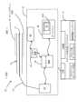
図1に示されるように、血管への挿入の前又は後のプローブ7が示されている。プローブ7は、一実施形態では、OCTに加えて、又はOCTの代わりに、超音波などの他の撮像モダリティを含んでよい。プローブ7は、OCTシステム10又は他の撮像システム(例えば、IVUSシステム)と光通信をしている。光ファイバ15を介してプローブ7とつながるOCTシステム又はサブシステム10は、レーザなどの光源と、サンプルアーム及び参照アームを有する干渉計と、様々な光路と、クロック発生器と、フォトダイオードと、他のOCTシステムコンポーネントと、を含んでよい。As shown in FIG. 1, the probe 7 is shown before or after insertion into a blood vessel. The probe 7 may, in one embodiment, include other imaging modalities, such as ultrasound, in addition to or instead of OCT. The probe 7 is in optical communication with an
システム10は、ステント外形分析ソフトウェア9を含む。このソフトウェアは、非過渡的命令として、1つ以上のメモリ装置、例えば、メモリ装置45に記憶されてよく、1つ以上のコンピューティング装置、例えば、コンピューティング装置40によって実行されてよい。ステント外形分析ソフトウェアは、1つ以上の外形(例えば、ユーザが生成するターゲット外形)、ステント前外形及びステント後外形又は他の外形を比較する為の比較器又は他の比較ソフトウェアルーチンを含んでよい。ステント外形分析ソフトウェア9は、配備されたステントの画像を、ターゲット外形、又は別のオーバレイの1つ以上のステント前外形又はステント後外形に対して相対的に重ね合わせることに適するオーバレイ方法を含んでよい。ソフトウェア9は又、側枝とステントが重なり合った場合にこれを識別する側枝閉塞インジケータソフトウェアモジュールを含んでよい。ソフトウェア9は又、プルバックとも呼ばれる第1及び第2の血管内データ収集セッションについて決定されるFFR、VRR、及び他の値を比較することが可能である。ステント外形分析ソフトウェア9は、本明細書に記載の方法及び特徴を実施する為に、図1に示されたソフトウェアコンポーネント及び他のものを含んでよい。ソフトウェア9は又、図5に示されるような他の血管内データ処理モジュールのパイプラインの一部であってもよい。The
一実施形態では、受光器31(例えば、平衡フォトダイオードベースのシステム)がプローブ7から出た光を受けることが可能である。コンピューティング装置40(例えば、コンピュータ、プロセッサ、ASIC、又は他の装置)が、OCTシステム10の一部であってよく、或いは、OCTシステム10と電気通信又は光通信をしている別個のサブシステムとして含まれてよい。コンピューティング装置40は、データ処理に適するメモリ、ストレージ、バス、及び他のコンポーネントと、ソフトウェア44、例えば、後述のようにステント可視化、ステント付着不良検出、及びプルバックデータ収集の為に構成された画像データ処理段階と、を含んでよい。In one embodiment, a light receiver 31 (e.g., a balanced photodiode-based system) can receive light emitted from the probe 7. A computing device 40 (e.g., a computer, processor, ASIC, or other device) can be part of the
一実施形態では、コンピューティング装置40は、ソフトウェアモジュール又はプログラム44を含むか、これにアクセスし、これは、例えば、側枝検出モジュール、ガイドワイヤ検出モジュール、内腔検出モジュール、ステント検出モジュール、中間マスク除去モジュール、強度平均化モジュール、ステント付着不良検出モジュール、ステント計画立案モジュール、ステント分析モジュール、FFR測定モジュール、VRR測定モジュールなどのソフトウェアモジュールである。ソフトウェアモジュール又はプログラム44は、画像データ処理パイプライン又はそのコンポーネントモジュールと、1つ以上のグラフィカルユーザインタフェース(GUI)とを含んでよい。収集されたOCTデータを血管及びステントの2次元図及び3次元図に変換する為の一例示的画像処理パイプライン50を図5に示す。画像データ処理パイプライン、又は本明細書に記載のいずれかの方法が、メモリに記憶され、1つ以上のコンピューティング装置(例えば、プロセッサ、デバイス、又は他の集積回路)により実行される。In one embodiment, the
図1に示されるように、ディスプレイ46が、情報47を表示する為の、システム10の一部であってもよく、情報47は、例えば、収集されたOCTデータを使用して生成される、血管の断面図及び長手方向図である。この、OCTに基づく情報47は、1つ以上のグラフィックユーザインタフェース(GUI)により表示されてよい。更に、この情報47は、OCT又はIVUSシステム及びデータ収集プローブを使用して取得された断面走査データ、長手方向走査結果、直径グラフ、ターゲットステント外径、近位基準値、遠位基準値、ステント留置前及びステント留置後のFFR値、又は基本的な距離測定値を含んでよく、これらに限定されない。コンピューティング装置40はソフトウェア又はプログラム44を含んでもよく、これは、1つ以上のメモリ装置45に記憶されてよく、側枝、膨らみ不足なステント領域、及び他のステント配備の測定値又は計算値、並びに他の血管形体を、テキスト、矢印、色分け、強調表示、輪郭線、又は他の適切な、人間又は機械が可読なしるしなどにより識別するように構成されてよい。As shown in FIG. 1, a
OCTデータがプローブによって取得され、メモリに記憶されたら、これを処理して情報47を生成してよく、情報47は、例えば、プルバック領域又はその一部の長さ方向の血管の断面図、長手方向図、及び/又は3次元図である。これらの図は、図面に示されるように、ユーザインタフェースの一部として描かれてよい。OCTシステムから取得された距離測定値を使用して生成された血管画像は、血管及び血管内に配置された物体についての情報を提供する。Once the OCT data has been acquired by the probe and stored in memory, it may be processed to generate
一実施形態では、一方法が1つ以上のステント外形(例えば、ターゲットステント外形)を生成し、これは、ステント前計画立案段階において、ユーザが1つ以上の基準フレームを選択することにより構成可能である。本方法は、あらかじめ設定されたターゲットステント外形と、ステント配備後の血管内腔領域との相対的な比較分析を実施する。本方法及び関連するユーザインタフェースは、ステントを移動させたり、ステントを除去したり、ステントを再配置したり、ステントを膨らませたりするよう、ユーザにアラートを出すことが可能である。この比較分析に基づいて、側枝閉塞の場所を識別して表示することも可能である。予測されたパラメータ値と、ステント配備後に測定又は算出された値とに関して、ステント配備の結果に基づいて変化するパラメータが表示されてよい。これらのパラメータは、パラメータの値が、計画立案段階で設定されたターゲットパラメータより小さいことの結果として、ステントを移動させるか、膨らませることが必要であるという指示をユーザに与えることが可能である。In one embodiment, a method generates one or more stent profiles (e.g., target stent profiles), which can be configured by a user during the pre-stent planning stage by selecting one or more reference frames. The method performs a comparative analysis of the pre-defined target stent profile and the vessel lumen area after stent deployment. The method and associated user interface can alert the user to move the stent, remove the stent, reposition the stent, or inflate the stent. Based on this comparative analysis, the location of the side branch occlusion can also be identified and displayed. Parameters that change based on the results of stent deployment can be displayed in terms of predicted parameter values and values measured or calculated after stent deployment. These parameters can provide an indication to the user that the stent needs to be moved or inflated as a result of the parameter values being smaller than the target parameters set during the planning stage.
本開示は、一部分において、ステントを可視化する、コンピュータベースの方法、システム、及び装置に関する。一実施形態では、本開示は、ステントが留置された血管の広がり、並びに、更なる広がりが必要かどうか、或いは、ステントの再配置が必要かどうか、を評価する方法に関する。これらの評価方法は、様々な状態(例えば、血管に対して相対的に広がった状態)のステントの1つ以上の図を表示し、画像化されたステントを、1つ以上の選択されたステント外形に対して相対的に比較することを含んでよい。一実施形態では、本方法は自動的に実施される。本開示の方法は、ステント外形分析ソフトウェアなどのソフトウェアにより実施されてよく、このソフトウェアは、ステント計画立案ソフトウェア及び病変準備ソフトウェアを含んでよい(又はその逆であってよい)。The present disclosure relates in part to computer-based methods, systems, and devices for visualizing a stent. In one embodiment, the present disclosure relates to methods for assessing the spread of a vessel in which a stent has been placed and whether further spread or repositioning of the stent is required. These assessment methods may include displaying one or more views of the stent in various states (e.g., spread relative to the vessel) and comparing the imaged stent relative to one or more selected stent profiles. In one embodiment, the methods are performed automatically. The methods of the present disclosure may be performed by software, such as stent profile analysis software, which may include stent planning software and lesion preparation software (or vice versa).
配備するステントの選択は、OCT、IVUS、血管造影、又は他のプローブデータを、ステント留置されていない血管セグメントに対して相対的に取得し、その後、ステント留置された血管と比較することにより、行われてよい。ステント計画のステント留置段階及びステント未留置段階は、1つ以上のグラフィックユーザインタフェース(GUI)の一部として、長手方向に続けて表示されるか、広がった状態または広がっていない状態の断面図として表示されてよい。そのようなインタフェースは、OCTシステム、IVUSシステム、血管造影システム、又は他のデータ収集システムによる取得された距離測定値を使用して生成される1つ以上の血管図を含んでよい。Selection of a stent for deployment may be made by acquiring OCT, IVUS, angiography, or other probe data relative to an unstented vessel segment and then comparing it to the stented vessel. The stented and unstented phases of the stent plan may be displayed sequentially longitudinally or as cross-sectional views in a dilated or undilated state as part of one or more graphic user interfaces (GUIs). Such interfaces may include one or more angiograms generated using distance measurements acquired by an OCT system, an IVUS system, angiography system, or other data acquisition system.
一実施形態では、本方法は、ステント前計画立案段階においてユーザが設定したターゲットステント広がり外形を受け取るステップを含む。本方法は又、そのターゲット外形を、ステント配備後の1つ以上の血管内腔領域と比較することも可能である。本方法は、ターゲットステント外形とステントの現在の広がりとを比較する為の正確なプロセスを提供する。ユーザが配備後のステントを広げることを1度しか試みることができない生体再吸収性ステント(BRS)の場合は、ステントを広げる必要がある領域を示すことが、どこでバルーンを膨らませ、どこで、ステントが広がった後のバルーンのサイズを選択するかを決定することにも役立つ。そこで、撮像プローブにより1回のプルバックが実施されて内腔環境が認識され、これが、ステント留置後の第2のプルバックの結果と比較される。第2のプルバックは、ステントを更に膨らませたり、再配置したり、除去したりできるように、ステント留置の直後に実施可能である。一実施形態では、ステント計画をGUIから入力してメモリに記憶させ、これを使用したり、他の血管内データ及び画像と比較したりすることが可能である。In one embodiment, the method includes receiving a target stent expansion profile set by the user during the pre-stent planning stage. The method can also compare the target profile to one or more areas of the vessel lumen after stent deployment. The method provides an accurate process for comparing the target stent profile to the current expansion of the stent. In the case of a bioresorbable stent (BRS) where the user can only attempt to expand the stent once deployed, indicating the area where the stent needs to be expanded also helps determine where to inflate the balloon and where to select the size of the balloon after the stent is expanded. Then, one pullback is performed by the imaging probe to recognize the lumen environment and this is compared to the result of a second pullback after stent deployment. The second pullback can be performed immediately after stent deployment so that the stent can be further expanded, repositioned, or removed. In one embodiment, the stent plan can be input from the GUI and stored in memory for use and comparison with other endovascular data and images.
ステント計画は、開始フレームなどの第1の場所と、終了フレームなどの第2の場所とを含んでよい。ステント計画は、複数のステント径を含んでよい。一実施形態では、ステント計画は、画像化された血管に沿う第1及び第2の場所と、第1及び第2の場所におけるステント径とを含む。ステント計画は、複数のフレームを含んでよく、これらのフレームは、血管内で光学的又は音響的に測定されたデータ及びパラメータ、例えば、光コヒーレンス断層撮影やIVUSのデータ及びパラメータを使用して生成される。これらのフレームは、1つ以上の期間において血管に対して相対的に取得された長手方向図、断面図、又は他の図又は画像又はデータを含んでよい。一例として、第1の期間は、第1のプルバックを含んでよく、この期間に血管が撮像される。同様に、第2の期間は、第2のプルバックを含んでよく、この期間に血管が撮像される。一実施形態では、ステント計画は、第1のフレーム及び第2のフレームに加えて、1つ以上のフレーム、例えば、第1のフレーム及び第2のフレーム、又は第1及び第2のフレームの間にあるフレーム、及びこれらの組み合わせにおけるステント径を含んでよい。一実施形態では、第1及び第2のフレームを含む各フレーム、又は第1及び第2のフレームに続く各フレームのステント径がステント計画に含まれる。The stent plan may include a first location, such as a start frame, and a second location, such as an end frame. The stent plan may include multiple stent diameters. In one embodiment, the stent plan includes first and second locations along the imaged vessel and stent diameters at the first and second locations. The stent plan may include multiple frames, which are generated using optically or acoustically measured data and parameters within the vessel, such as optical coherence tomography or IVUS data and parameters. The frames may include longitudinal, cross-sectional, or other views or images or data acquired relative to the vessel in one or more time periods. By way of example, the first time period may include a first pullback, during which the vessel is imaged. Similarly, the second time period may include a second pullback, during which the vessel is imaged. In one embodiment, the stent plan may include stent diameters in one or more frames in addition to the first and second frames, such as the first and second frames, or frames between the first and second frames, and combinations thereof. In one embodiment, the stent plan includes stent diameters for each frame including the first and second frames, or each frame following the first and second frames.
光コヒーレンス断層撮影(OCT)は、サンプル、例えば、血管又は血管内に配置された物体などに対して相対的な距離測定値を、干渉計を使用して取得する撮像モダリティである。血管内超音波、即ちIVUSは、超音波又は音響波ベースの撮像モダリティである。これらの一方又は両方が、血管内データ収集プローブにおいて組み合わされてよい。図2に示されるように、血管5は、データ収集プローブ7により撮像されてよい。図2に示されるように、ガイドワイヤ8を使用して、プローブ7が血管5内に導入されてよい。プローブなどにより収集されたデータから生成された、血管の画像又はデータの例を、図3、図4、及び図5に示す。Optical coherence tomography (OCT) is an imaging modality that uses interferometry to obtain distance measurements relative to a sample, such as a blood vessel or an object placed within a blood vessel. Intravascular ultrasound, or IVUS, is an ultrasound or acoustic wave based imaging modality. Either or both of these may be combined in an intravascular data collection probe. As shown in FIG. 2, a blood vessel 5 may be imaged by a data collection probe 7. As shown in FIG. 2, the probe 7 may be introduced into the blood vessel 5 using a guide wire 8. Examples of images or data of a blood vessel generated from data collected by a probe or the like are shown in FIG. 3, FIG. 4, and FIG. 5.
データ収集プローブ7は、血管5の長さ方向に導入され、プルバックされて、その間にデータを収集することが可能である。血管の長さ方向に光ファイバが引き込まれる(プルバックされる)際に、プローブ又はその一部分が回転して、複数の走査結果又はOCTデータセットが収集される。これが、一実施形態では、プルバックと称される。これらのデータセットを使用して、関心対象領域を識別することが可能であり、例えば、狭窄領域やステント12のようなステントが配備された領域を識別することが可能である。一実施形態では、第1のプルバックがステント配備前に実施され、第2のプルバックがステント配備後に実施される。第1及び第2のプルバックの両方の間に、画像化された血管に対して相対的に血管造影データが生成されてよい。第1のプルバックと第2のプルバックとの間で、関心対象領域及びパラメータ、例えば、血管抵抗比、FFR、内腔領域、内腔外形、及び他のパラメータを比較することが可能である。The data collection probe 7 can be introduced along the length of the blood vessel 5 and pulled back while collecting data. As the optical fiber is retracted (pulled back) along the length of the blood vessel, the probe or a portion thereof rotates and multiple scans or OCT data sets are collected, which in one embodiment are referred to as pullbacks. These data sets can be used to identify regions of interest, such as stenosis and regions where a stent, such as
一実施形態では、データ収集プローブ7は、干渉計及びデータ処理システムを含むOCTシステム10とともに使用するように構成されたOCTプローブである。OCTプローブ7を使用して収集された距離測定値を処理して、画像データのフレーム、例えば、血管の断面図又は長手方向図(Lモード図)を生成することが可能である。明確にする為に、断面図は、長手方向図を含んでよく、これは限定ではない。これらの画像は、本明細書において概説されているような1つ以上の画像データ処理モジュール又は段階により、処理されてよい。In one embodiment, the data collection probe 7 is an OCT probe configured for use with an
図2に示される血管5においては、ステント12が血管の内腔14に配置されており、様々なタイプのデータ収集プローブ及び関連するOCTシステムが使用可能である。一実施形態では、OCTシステム10は、様々なデータ処理段階又はモジュールを実行するように構成されたプロセッサ、メモリ、又は他のコンポーネントを含む。これらの段階又はモジュールは、画像データに対して動作し、画像データを変換する。これらのモジュール又は段階は、ステント検出ソフトウェアコンポーネント及びステント付着不良検出コンポーネントを含んでよい。所与のステント及びその構成要素が、ステントの構成要素である1つ以上のステントストラットと血管壁との間の接触又は接触不足の度合いの表示又は測定値を含むように可視化されてよい。ステント12及び壁26に対するステントの膨らみ不足の度合いを示す1つの領域が、領域18として示されている。図4及び図5の表示は、ユーザが、そのような状況においてステントを更に膨らませる為の診断として使用してよい。本明細書では、これらの特徴に関して、更に詳細に説明している。2 shows a blood vessel 5 with a
図2に示されるように、所与の血管においては、血管の壁が、血液が流れる内腔を画定する。血管造影システム13によって提供されるような、X線ベースの撮像モダリティを使用して、血管を撮像し、ステント配備又はステント可視化を促進することが可能である。更に、本明細書に記載のように、血管5への挿入に適するプローブ7を使用して、所与の血管の断面の画像を生成することが可能である。OCTシステム及び関連するデータ収集プローブにより取得された、血管の様々な断面図及び3次元図を使用して、狭窄領域、又はステント12のような配備済みステント(これは内腔14に配置されている)を表示することが可能である。As shown in FIG. 2, in a given blood vessel, the walls of the vessel define a lumen through which blood flows. An X-ray based imaging modality, such as that provided by
図2は、側枝検出、内腔検出、ガイドワイヤ検出、及び他の様々な処理を実施することに適するデータ収集プローブ及びOCTシステム10を示す高レベル概略図である。OCTシステム10は、本明細書に記載の用途及びデータ収集のコヒーレンス及び帯域幅の要件を満たす適切な光源を含んでよい。プローブ7はカテーテル20を含んでよく、カテーテル20には、1つ以上の光ファイバ15と、プローブ先端17とが中に配置されているカテーテル部分がある。プローブ先端17は、一実施形態では、ビーム誘導器を含む。2 is a high-level schematic diagram of a data collection probe and
図示されるように、カテーテル20は、動脈内腔などの内腔14に導入される。プローブ7は、回転するか摺動可能なファイバ15を含んでよく、ファイバ15は、光を内腔14の内部に誘導するか、ファイバ15の長手軸に垂直な方向に誘導する。結果として、ファイバ15が回転すると光がプローブの側面から誘導される場合、OCTデータは、血管5の壁25に対して収集される。血管25の壁が内腔境界を画定する。この内腔境界は、内腔検出ソフトウェアコンポーネント又はモジュールを使用して、プローブ先端17で収集された光信号から取得された距離測定値から検出可能である。ファイバの代わりに、血管壁及び1つ以上のステントに関するIVUS信号を収集することに適する超音波トランスデューサが使用されてもよい。As shown, the
内腔検出ソフトウェアは、1つ以上のステップを含んでよい。例えば、一実施形態では、内腔検出を実施する為に、フィルタ又は他の画像処理装置を2次元画像に適用して、画像中の、内腔境界を表すエッジを検出することが可能である。別の実施形態では、走査線ベースの方法が用いられる。1回以上のプルバックの間に、血管と、血管の内腔に配置された1つ以上のステントと、に対する走査線として、光信号又は超音波信号が収集される。一実施形態では、コンピューティング装置で実行される内腔検出ソフトウェアが、コンピューティング装置を使用して、一連の走査線から1つ以上の画像を生成する。The lumen detection software may include one or more steps. For example, in one embodiment, to perform lumen detection, a filter or other image processing device may be applied to the two-dimensional image to detect edges in the image that represent the lumen boundary. In another embodiment, a scan-line based method is used. During one or more pullbacks, optical or ultrasound signals are collected as scan lines of the blood vessel and one or more stents disposed in the lumen of the vessel. In one embodiment, the lumen detection software running on the computing device uses the computing device to generate one or more images from a series of scan lines.
更に、内腔検出は、コンピューティング装置を使用して、血管画像のバイナリマスクを生成するステップを含んでよく、バイナリマスクは強度閾値を使用して生成される。別のステップとして、バイナリマスク内で複数の走査線が定義される。この複数の走査線のうちの各走査線に関しては、一実施形態では、内腔境界組織として識別される領域がその上にある。この境界の輪郭セグメントが、内腔境界組織の領域の存在に基づいて識別される。一実施形態では、本方法は、隣接する輪郭セグメントを識別する。この内腔境界検出方法は、隣接する輪郭セグメント同士の間の欠落している輪郭データを補間するステップを含んでもよい。結果として、一実施形態では、隣接する輪郭セグメント、及び欠落していて補間された輪郭データが、内腔境界を画定する。Further, the lumen detection may include using a computing device to generate a binary mask of the vascular image, the binary mask being generated using an intensity threshold. As another step, a plurality of scanlines are defined within the binary mask. For each scanline of the plurality of scanlines, in one embodiment, there is an area thereon that is identified as lumen border tissue. A contour segment of the boundary is identified based on the presence of the area of lumen border tissue. In one embodiment, the method identifies adjacent contour segments. The lumen border detection method may include the step of interpolating missing contour data between adjacent contour segments. As a result, in one embodiment, the adjacent contour segments and the missing and interpolated contour data define the lumen boundary.
図2に示されるように、プローブ先端17は、点線A、Bで境界が示されている、血管5のステントが留置された領域より遠位にあるように内腔14に配置されている。プローブ先端17は、光を送出し、(例えば、ステント12などの)物体や血管5の壁25からの後方散乱光を受けるように構成されている。プローブ先端17及びデータ収集プローブ7のその他の部分は、線A、Bで画定されている、ステントが留置された領域を先端が通過するように、内腔14を通って引っ張られる。ユーザが選択した基準フレームに対する応答として生成されたターゲットステント外形(TSP)が、配備されたステントの線A及びBの間に示されている。ターゲットステント外形は、本明細書に記載の1つ以上の方法により生成され、この方法は、ユーザが提供した1つ以上の基準フレーム、又は他の、識別された血管の一部分に対して相対的に選択されるものを入力としてを含む。一実施形態では、ターゲットステント外形は、図5に示されるような、内腔外形のうちの、検出されたステントストラットに対応する領域の上に自動的に置かれるかオーバレイされる。As shown in FIG. 2, the
従って、本開示は、一部分において、血管、ステント、又は他の、関心対象の血管情報に関する情報を評価及び描写することに適するソフトウェアベースの方法並びに関連するシステム及び装置に関する。最初のステント配備又はステント関連の修正処置の前又は後に、OCTデータを使用して、血管の断面図や長手方向図などの2-D図を生成することが可能である。データ収集プローブ及び様々なデータ処理ソフトウェアモジュールを使用して取得されたOCTデータを使用して、ステント、及び/又は、ステント及び/又はステントが配置されている内腔に関連する1つ以上の特性を識別し、特徴化し、可視化することが可能である。Accordingly, the present disclosure relates in part to software-based methods and associated systems and devices suitable for evaluating and depicting information related to a blood vessel, stent, or other vascular information of interest. OCT data can be used to generate 2-D views, such as cross-sectional and longitudinal views, of the blood vessel before or after initial stent deployment or a stent-related revision procedure. OCT data acquired using a data collection probe and various data processing software modules can be used to identify, characterize, and visualize one or more properties associated with the stent and/or the lumen in which the stent is located.
更に、そのような2次元画像又は3次元画像が生成されているか、基本的な測定値がデータベースやメモリ装置などのデータ記憶場所において利用可能であると、血管及びステントに対して相対的な測定値を取得することにより、診断作業を更に強化することが可能である。例えば、ステント外形がずれている度合いのような、ステントに関連する測定値を、OCTデータを使用して自動的に生成することが可能であり、その場合、ユーザが計算に関与する必要はない。Furthermore, once such 2D or 3D images have been generated or basic measurements are available in a data store such as a database or memory device, the diagnostic task can be further enhanced by obtaining measurements relative to the vessel and stent. For example, measurements related to the stent, such as the degree to which the stent profile is misaligned, can be generated automatically using the OCT data without the user having to be involved in the calculations.
一実施形態では、図2に示されるように、血管造影システム13を使用して、関心対象の血管の高レベル図を取得することが可能である。このステップは、回転可能OCTプローブのプルバックより先に行われてよく、同時に行われてもよい。そのような手順の一例として、ユーザとの間に相関関係又は相関関係の不足があるように、ステント外形及びステント外形の不整合がソフトウェアによって自動的に特定されて表示された場合、ユーザは、配備されたステントを更に膨らませる為にバルーンを使用することを選択してよい。バルーンは、血管造影システム13の支援を受けて配置されることが可能であり、バルーンを膨らませて、ステントの状態を変化させ、膨らみ不足の度合いを減らすことが可能である。一実施形態では、設置されたステントを点検する為に、更なるOCTプルバックを実施してよい。ステントの検出、ステントの配置、及び内腔の検出は、画像又はOCTデータを入力とする、画像データ処理パイプライン内に編成された複数のソフトウェアモジュールを使用して実施されてよい。In one embodiment, as shown in FIG. 2, an
ステント計画立案段階では、血管内データ収集システムと電気通信をしている、プロセッサやマイクロプロセッサなどのコンピューティング装置を使用して、ターゲットステント広がり外形(TSP、即ちターゲットステント外形とも称される)を決定する。ターゲットステント外形は、1つ以上のユーザ選択に基づいて生成され、これらのユーザ選択は、例えば、図3に示されるような、近位領域及び遠位領域においてユーザが選択した基準領域である。近位基準及び遠位基準を、関連する内腔径とともに設定することにより、ユーザは、血管のうちの、ターゲット領域であるセグメントをステント留置対象として定義する。図3では、近位基準領域及び遠位基準領域における内腔径と中間枝径とにより、近位基準領域と遠位基準領域とをつなぐ最適なステント留置先細形状が生成される。図3の縦の点線は、最小内腔面積値(MLA)である。In the stent planning stage, a computing device, such as a processor or microprocessor, in electrical communication with the endovascular data collection system is used to determine a target stent spread profile (TSP, also referred to as target stent profile). The target stent profile is generated based on one or more user selections, such as user-selected reference regions in the proximal and distal regions, as shown in FIG. 3. By setting the proximal and distal references along with the associated lumen diameters, the user defines the target region, a segment of the vessel, for stent placement. In FIG. 3, the lumen diameters and mid-branch diameters at the proximal and distal reference regions generate an optimal stent placement taper shape connecting the proximal and distal reference regions. The vertical dotted line in FIG. 3 is the minimum lumen area value (MLA).
ステント外形は、基準フレーム間の所与のセグメントにおいて一定不変である。枝の端から端までの外形は直線補間されている。即ち、血管をその長さ方向に生理学的に先細化することと、近位基準及び遠位基準とにより、ターゲットステント外形の上方境界及び下方境界が生成される。基準フレームが同じセグメントにある場合(即ち、基準フレーム間に枝がない場合)、ステント外形は、2つの基準フレームの間の直線補間になる。The stent profile is constant for a given segment between the reference frames. The profile from end to end of the branches is linearly interpolated; that is, the physiological tapering of the vessel along its length and the proximal and distal references generate the upper and lower boundaries of the target stent profile. If the reference frames are in the same segment (i.e., there are no branches between the reference frames), then the stent profile is a linear interpolation between the two reference frames.
一実施形態では、本方法は、遠位基準径が近位基準径より小さい場合には、遠位から近位に向かう各枝点においてターゲットステント外形をステップアップすることにより、外形の幾何学的形状を調節する。遠位基準径が近位基準径より大きい場合には、本方法は、遠位から近位に向かう各セグメントにおいてターゲットステント外形をステップダウンする。このようにして、基準エンドポイントのユーザ選択と、血管及び関連付けられた流れの先細特性と、側枝に起因する他の変化とが考慮され、モデル化されて、ステント留置によって引き起こされるであろう、予想される変化が認識される。In one embodiment, the method adjusts the geometry of the profile by stepping up the target stent profile at each branch point going from distal to proximal if the distal reference diameter is less than the proximal reference diameter. If the distal reference diameter is greater than the proximal reference diameter, the method steps down the target stent profile at each segment going from distal to proximal. In this manner, the user selection of the reference end points, the tapering characteristics of the vessel and associated flow, and other changes due to side branches are considered and modeled to recognize the expected changes that would be caused by stent placement.
遠位基準フレームと近位基準フレームが同じセグメントにある場合、ステント外形は、遠位基準フレームと近位基準フレームとの間の直線補間になる。一実施形態では、ユーザが選択した1つ以上の基準フレームに対する応答としてターゲットステント外形を決定する方法は、以下のとおりである。
基準フレーム間の側枝の総数をNとする。
例えば、図3では、図示されているセグメントの最遠位フレームと最近位フレームとの間に4本(N=4)の側枝が示されている。1本の側枝が内腔の上部にあり、3本の側枝が下部にある。
exp=2.3はスケーリング指数である。一実施形態では、指数値の範囲は、約2以上から約3以下である。この指数値は、ユーザが選択した基準フレームの間のセグメントの先細形状のスケーリングを示す。指数の最良値の選択は、血管の先細形状、及びそれらの血管の枝径が測定されている、OCT及び血管造影の画像データベースの統計的分析に基づいて行われる。通常の被験体では、指数値の範囲は約2.2から約2.7である。
近位基準径と遠位基準径との差は次式のとおりである。

各枝におけるセグメントの増分は、スケーリング則指数でべき乗される枝径に比例する。

Let N be the total number of side branches between the reference frames.
For example, in Figure 3, four (N=4) side branches are shown between the most distal and most proximal frames of the illustrated segment: one side branch at the top of the lumen and three at the bottom.
exp=2.3 is the scaling exponent. In one embodiment, the exponent value ranges from about 2 or more to about 3 or less. This exponent value indicates the scaling of the segment taper between the user selected reference frames. Selection of the best value of the exponent is based on a statistical analysis of an OCT and angiography image database in which the taper of vessels and their branch diameters are measured. In normal subjects, the exponent value ranges from about 2.2 to about 2.7.
The difference between the proximal and distal reference diameters is:
The segment increment in each branch is proportional to the branch diameter raised to the power of a scaling law exponent.
上述のセグメント径はデルタ測定値を与えており、血管セグメントの全体にわたって先細境界が生成されていると、ターゲットステント外形の上部及び下部先細形状の境界は、デルタ測定値などの量が段階的に変化する。ステント配備前又はステント計画立案段階では、ターゲットステント広がり外形(ステント前ターゲット)は、ユーザにとってのターゲットを設定する。ユーザインタフェースは、ステントサイズの選択肢を提示して、ユーザが、所与のターゲット外形に対して適切にサイズ決定されたステントを選択することを支援する。The segment diameters described above provide a delta measurement, and when a tapered boundary is generated throughout the vessel segment, the upper and lower tapered boundaries of the target stent profile are stepped in amounts such as the delta measurement. During the pre-stent deployment or stent planning stage, the target stent spread profile (pre-stent target) sets a target for the user. The user interface presents stent size options to assist the user in selecting an appropriately sized stent for a given target profile.
ステントが配備された後、ステント検出アルゴリズムは、ステントが留置された内腔領域の位置を特定する。ステントが留置された領域の内腔外形は、ステント前ターゲットと比較される。広がりすぎ又は広がり不足があれば、ユーザが分析することに備えて、自動的に強調表示されることが可能である。定量化された誤差測度を生成することが可能であり、これは、ステント後内腔外形とステント前ターゲット外形との間のフレーム当たり誤差又はセグメント当たり誤差を示す。この誤差測度は、ユーザが、留置後のステントを広げる際に、適切なサイズのバルーンを選択することを支援することが可能である。この誤差測度は、ステント後内腔外形とステント前ターゲット外形との差となる距離を含んでよい。After the stent is deployed, a stent detection algorithm locates the stented lumen area. The lumen contour of the stented area is compared to the pre-stent target. Any over- or under-expansion can be automatically highlighted for user analysis. A quantified error measure can be generated that indicates the per-frame or per-segment error between the post-stent lumen contour and the pre-stent target contour. This error measure can assist the user in selecting an appropriate size balloon to expand the stent after deployment. This error measure can include the distance that the post-stent lumen contour differs from the pre-stent target contour.
一実施形態では、ステント外形又はステント計画立案ソフトウェアは、ステント前計画立案段階において、予測されるVFR又はFFR又は他の血管内パラメータを使用し、これを、ステント後に達成されたVFR又はFFR又は他の血管内パラメータと比較する。予測されたFFR-ステント留置後のFFRのような測定値の差も、ステント配備に関連する変化に対してユーザを誘導する為に表示されてよい。これらのパラメータ同士の値が近い場合、支援されたステント留置は、予測された結果を達成し、それらの差が優位である場合は、ステントを再留置するか、更に膨らませることが必要になる可能性がある。この比較の結果として、ステントの広がりレベルを変更する必要がある場合、ユーザインタフェースは、バルーンを膨らませる領域を血管の画像上で識別することにより、自動的にガイダンスを与えることが可能である。In one embodiment, the stent profile or stent planning software uses the predicted VFR or FFR or other endovascular parameters in the pre-stent planning stage and compares this to the achieved VFR or FFR or other endovascular parameters after stenting. The difference between the measurements, such as predicted FFR - post-stenting FFR, may also be displayed to guide the user to the changes related to stent deployment. If the values of these parameters are close, the assisted stenting will achieve the predicted results, if the differences are significant, the stent may need to be repositioned or further inflated. If the comparison results in the need to change the stent expansion level, the user interface can automatically provide guidance by identifying areas on the vessel image where the balloon should be inflated.
本システムは、VFR値の改善量を表示することも可能であり、ステント後分析段階においてユーザを更に支援することが可能である。側枝閉塞の発生は、前後のセグメント画像データを比較することによって表示可能であり、そのような閉塞が配備済みステントの移動を必要とする場合にはインジケータを使用して表示可能である。The system can also display the amount of improvement in VFR values, further assisting the user in the post-stent analysis phase. The occurrence of side branch occlusion can be displayed by comparing pre- and post-segment image data, and an indicator can be used if such occlusion requires migration of the deployed stent.
ステント後内腔との比較にはステント前外形が使用されるが、これは、ステント後プルバックだけを使用して計算されたステント外形は、ステント配備中に閉塞又はブロックされた側枝を考慮することが全くできない為である。The pre-stent profile is used to compare with the post-stent lumen because a stent profile calculated using only the post-stent pullback does not account for any side branches that may be occluded or blocked during stent deployment.
血管内撮像された血管を、ステントの配置、ステントの選択、及びステントの広がりレベルの評価に使用することを可能にする例示的ワークフローを以下に示す。遠位基準フレームと近位基準フレームが同じセグメントにある場合、ステント外形は、遠位基準フレームと近位基準フレームとの間の直線補間になる。Below is an exemplary workflow that allows intravascularly imaged vessels to be used for stent placement, stent selection, and assessment of stent spread level. If the distal and proximal reference frames are in the same segment, the stent profile is a linear interpolation between the distal and proximal reference frames.
ステント前計画立案:医師は、ステントを留置する、血管の、病変又は他の狭窄があるセグメントと、ステントのサイズとを、ステント計画立案ツールを使用して決定する。このツールは、図3に示されるようなユーザインタフェース表示を含んでよい。基準を選択すると、可能なステントサイズの範囲が指定される。ユーザが選択した第1の基準R1が、インタフェースの左側、即ち、遠位側に図示されている。ユーザが選択した第2の基準R2が、インタフェースの右側、即ち、近位側に図示されている。このプロセスは、1つ以上の血管内データセットに関連する表示及びメトリクスを含んでよい1つ以上のユーザインタフェースを使用して実施される。ユーザが与えた基準フレームに基づくターゲットステント外形TSPは、水平線で示される上方境界及び下方境界を有する内腔外形輪郭に対して相対的に狭くなるように示されている。内腔外形LPは、血管の中心に沿ってターゲットステント計画の両側に示されており、上方輪郭及び下方輪郭に、図3に示されるようなTSPによって境界がつけられている。Pre-stent planning: The physician uses a stent planning tool to determine the segment of the vessel where the stent is to be placed, which has a lesion or other stenosis, and the size of the stent. The tool may include a user interface display as shown in FIG. 3. Selection of criteria specifies a range of possible stent sizes. A first user-selected criterion R1 is shown on the left, or distal, side of the interface. A second user-selected criterion R2 is shown on the right, or proximal, side of the interface. This process is performed using one or more user interfaces, which may include displays and metrics related to one or more endovascular data sets. A target stent profile TSP based on a user-provided frame of reference is shown narrow relative to the lumen profile contour, with upper and lower boundaries shown as horizontal lines. A lumen profile LP is shown on either side of the target stent plan along the center of the vessel, bounded by the upper and lower contours by the TSP as shown in FIG. 3.
これらのデータセットは、血管内を通るプルバックの間に取得されたOCT又はIVUSのデータセットを含んでよい。図3では、血管の画像の中に4つの側枝SB1-SB4が示されている。内腔は、中央の暗い領域として示されており、左側に遠位端、右側に近位端がある。縦の点線はMLAに相当する。ステントを配置することの決定は、VFR、又は測定されたFFRに基づいてよい。基準フレームを選択すると、その応答として、予測されるVFR(VFRp)、ステント長、及びターゲットステント外形が生成される。これらの値を、計画立案時に期待されたVFR又はFFR、並びに、ステント配備後に取得された測定値を使用して比較して、血管内のステントの効果、並びに、更に膨らませるか、ステント留置をやりなおすことの必要性を評価することが可能である。These data sets may include OCT or IVUS data sets acquired during pullback through the vessel. In FIG. 3, four side branches SB1-SB4 are shown in the image of the vessel. The lumen is shown as the central dark area with the distal end on the left and the proximal end on the right. The vertical dotted line corresponds to the MLA. The decision to place a stent may be based on the VFR or the measured FFR. A reference frame is selected and in response a predicted VFR (VFRp), stent length, and target stent profile are generated. These values can be compared with the VFR or FFR expected during planning and with measurements acquired after stent deployment to assess the effect of the stent in the vessel and the need for further inflation or redoing the stent placement.
ステント後分析:図4のインタフェースまたは表示の表現において示されるようなステントが配備された後、血管、及び新しく配備されたステントに対して相対的な血管内データを収集する、新たなプルバックが取得される。新たなプルバックで示されるように、図3とは対照的に、図4に示される第2のプルバックでは、ステント留置後に2つの側枝SB1及びSB4がブロックされており、2つの側枝SB2及びSB4だけが検出されている。一実施形態では、ステント外形分析ソフトウェアは、ステント検出機能を用いて、ステントが留置された領域を自動的に識別する。ステントが留置された領域の内腔外形LPは、図5に示されるように、ターゲットステント外形TSPがオーバレイされて表示される。Post-stent analysis: After the stent is deployed as shown in the interface or display representation of FIG. 4, a new pullback is taken to collect endovascular data relative to the vessel and the newly deployed stent. As shown in the new pullback, in contrast to FIG. 3, in the second pullback shown in FIG. 4, two side branches SB1 and SB4 are blocked after stent placement, and only two side branches SB2 and SB4 are detected. In one embodiment, the stent profile analysis software automatically identifies the stented area using a stent detection function. The lumen profile LP of the stented area is displayed with the target stent profile TSP overlaid as shown in FIG. 5.
図5に示されるように、ステント留置後に、OCT又はIVUSプルバックなどの第2のデータ収集セッションにおいて取得されたVFR値は、ステント前計画立案段階の(予測された)VFRpとともに表示される。ステント後のVFRがステント前計画立案段階のVFRpより小さい場合、ステントは所望のターゲットより下方に配備されたが、VFRpより大きい場合、ステントは、ターゲットVFRを首尾よく満たして配置された。ステント配備の前後のプルバックを使用する、これらの診断示差測定は、ステントが留置された血管及び関連する1つ以上のステントに対して相対的に何らかの変更が行われたとしたらどうなるかについての評価を促進する。As shown in FIG. 5, the VFR value obtained in a second data collection session, such as an OCT or IVUS pullback, after stent placement is displayed along with the (predicted) VFRp of the pre-stent planning stage. If the post-stent VFR is less than the pre-stent planning stage VFRp, the stent was deployed below the desired target, whereas if it is greater than the VFRp, the stent was successfully placed meeting the target VFR. These diagnostic differential measurements using pullbacks before and after stent deployment facilitate the assessment of what would have happened if any changes had been made relative to the stented vessel and the associated stent(s).
図示されるように、図5では、内腔外形が示されており、計画されたステント前ターゲット外形が点線で示されている。ステント外形は、内腔外形LPのうちの、検出されたステントストラットに対応する領域の上に自動的に配置される。図5の下部パネルに、検出されたステントストラットの長手方向図が示されている。図5では、ステントは、図示されているように、ターゲットステント外形に対して相対的に膨らみ不足である。ターゲットステント外形は、図5において点線で示されている上方先細境界及び下方先細境界を含む。これが起こるのは、画像処理パイプラインによって識別されたステントの検出されたストラットが、図示されている水平線まで広がらない為である。図5は、近位基準及び遠位基準によって選択された血管セグメントを表しており、これは、ステント及びターゲットステント外形の概略表示を含む。このインタフェースは、様々な角度から見ることができるステントの画像を下部パネルに含んでよい。図5のユーザインタフェース表示のパネルは、その全てが同時に表示される必要はないが、そのうちの1つ以上が、ステント配備後にステントを膨らませるかどうか、移動させるかどうか、或いは定位置に放置するかどうかをユーザが決定することを支援することが可能である。As shown, in FIG. 5, the lumen profile is shown and the planned pre-stent target profile is shown in dotted lines. The stent profile is automatically placed over the regions of the lumen profile LP that correspond to the detected stent struts. In the bottom panel of FIG. 5, a longitudinal view of the detected stent struts is shown. In FIG. 5, the stent is relatively underbulged relative to the target stent profile as shown. The target stent profile includes upper and lower tapered boundaries shown in dotted lines in FIG. 5. This occurs because the detected struts of the stent identified by the image processing pipeline do not extend to the horizontal line shown. FIG. 5 represents a vessel segment selected by proximal and distal fiducials, which includes a schematic representation of the stent and the target stent profile. The interface may include images of the stent in the bottom panel that can be viewed from various angles. The panels of the user interface display of FIG. 5 need not all be displayed at the same time, but one or more of them can assist the user in deciding whether to inflate, move, or leave the stent in place after stent deployment.
収集されたOCTデータを血管及びステントの2次元図及び3次元図に変換し、配備されたステントに対して外形を相対比較する為の一例示的画像処理パイプライン50を、図6に示す。画像データ処理パイプライン、又は本明細書に記載のいずれかの方法が、メモリに記憶され、1つ以上のコンピューティング装置(例えば、プロセッサ、デバイス、又は他の集積回路)により実行される。一実施形態では、コンピューティング装置40は、ソフトウェアモジュール又はプログラム44を含むか、これにアクセスし、これは、例えば、側枝検出モジュール、ガイドワイヤ検出モジュール、内腔検出モジュール、ステント配備分析ソフトウェア(例えば、図1のソフトウェア9)、及び他のソフトウェアモジュールである。ソフトウェアモジュール又はプログラム44は、画像データ処理パイプライン又はそのコンポーネントモジュールと、1つ以上のグラフィカルユーザインタフェース(GUI)とを含んでよい。An exemplary
図6に示されるように、収集された血管内データを使用して生成された、血管の断面図及び長手方向図(例えば、図3、図4、及び図5の血管セグメント図及び外形、並びに他の、本明細書に記載のもの)のような情報を表示する為に、ディスプレイ46がシステム10の一部分であってもよい。この情報47は、1つ以上のグラフィックユーザインタフェース(GUI)を使用して表示されてよい。更に、この情報47は、限定でなく、断面走査データ、長手方向捜査結果、内腔外形、VRR値、FFR値、ステント、付着不良の面積、内腔境界、側枝閉塞、及び他の、血管の画像又は表現、或いは、システム10及びデータ収集プローブを使用して取得された基本的な距離測定値を含んでよい。コンピューティング装置40はソフトウェア又はプログラム44を含んでもよく、これは、1つ以上のメモリ装置に記憶されてよく、ターゲットステント外形、内腔輪郭、及びステント計画と配備されたステント及び他血管形体の結果とのずれを、テキスト、矢印、色分け、強調表示、輪郭線、又は他の適切な、人間又は機械が可読なしるしなどにより識別するように構成されてよい。As shown in FIG. 6, a
OCTデータがプローブによって取得され、メモリに記憶されたら、これを処理して情報を生成してよく、情報は、例えば、プルバック領域又はその一部の長さ方向の血管の断面図、長手方向図、及び/又は3次元図である。これらの図は、図3、図4、及び図5に示されるように、ユーザインタフェースの一部として示されてよい。OCTシステムから取得された距離測定値を使用して生成された血管画像は、血管及び血管内に配置された物体についての情報を提供する。Once the OCT data has been acquired by the probe and stored in memory, it may be processed to generate information, such as cross-sectional, longitudinal, and/or three-dimensional views of the vessel along the length of the pullback region or a portion thereof. These views may be shown as part of a user interface, such as those shown in Figures 3, 4, and 5. Images of the vessel generated using distance measurements acquired from the OCT system provide information about the vessel and objects located within the vessel.
図示されるように、パイプラインは、血管を撮像する最初のプルバックの後に来るであろうステント配備後プルバックデータ52を受けてよい。ユーザ選択がGUI経由で受けられてよく、ステント計画データは、図1のソフトウェア9のようなステント外形又はステント配備分析ソフトウェアに転送されてよい。ガイドワイヤ54、側枝検出56、ステント検出58、及び内腔検出の各モジュールは、収集された走査線であってよいステント配備後プルバックデータに対して動作してよい。ソフトウェア62は、本明細書に記載の様々なステップを実施してよく、例えば、外形のオーバレイ、パラメータ比較(例えば、ステント留置の前後のVFR)、及びステント計画及び血管にステントを留置した結果からの差を実施してよい。As shown, the pipeline may receive post-stent
図7は、配備されたステントに対して相対的な診断評価を実施する為の一例示的プロセスフローを示す。一実施形態では、本方法はステップAからE、又はその一部を含み、これは、血管内撮像システムからの1つ以上のユーザ選択を伴う。一実施形態では、ステップAは、血管内データを使用して血管の一セグメントの表現を生成することを含む。一実施形態では、ステップBは、血管の一セグメントの表現に対して相対的な第1の基準の選択を受けることを含む。第1及び第2の基準は、血管内セグメント表現のフレーム又は他の部分を含んでよい。Figure 7 illustrates an exemplary process flow for performing a relative diagnostic evaluation on a deployed stent. In one embodiment, the method includes steps A through E, or portions thereof, involving one or more user selections from an intravascular imaging system. In one embodiment, step A includes generating a representation of a segment of a vessel using the intravascular data. In one embodiment, step B includes receiving a selection of a first criterion relative to the representation of the segment of the vessel. The first and second criterion may include a frame or other portion of the intravascular segment representation.
これらの基準はユーザインタフェースによって生成され、ユーザインタフェースは、ソフトウェア9、又は他の、本明細書に記載のソフトウェアコンポーネントに信号又はコマンド命令を伝達する。一実施形態では、ステップCは、血管の一セグメントの表現に対して相対的な第2の基準の選択を受けることを含む。一実施形態では、ステップDは、第1の基準及び第2の基準を使用してターゲットステント外形を生成することを含む。一実施形態では、ステップEは、ステントを血管内に配備した後に血管内腔外形を生成することを含む。一実施形態では、ステップFは、ターゲットステント外形を、血管内腔外形の1つ以上の領域と比較することを含む。一実施形態では、ステップGは、比較による1つ以上の差を含む出力を表示することを含む。These criteria are generated by a user interface, which communicates signals or commands to
典型的には、OCT画像、例えば、図5の、検出されたステントストラットを含む、下部パネルの長手方向画像が、一度に1つの走査線で取得される。カテーテルの中心から最大撮像深度に向けて発せられる光線に沿う一連のサンプルが、走査線と称される。従って、所与の走査線は、ステントストラット又はステント部分の1次元キュー又はしるしに対応しうる。プローブが回転するにつれて、走査線が収集されて、断面画像が形成される。Typically, OCT images, e.g., the longitudinal image of FIG. 5, bottom panel, including detected stent struts, are acquired one scan line at a time. A series of samples along a ray emanating from the center of the catheter toward the maximum imaging depth is referred to as a scan line. Thus, a given scan line may correspond to a one-dimensional cue or indicia of a stent strut or stent portion. As the probe rotates, scan lines are collected to form a cross-sectional image.
図1及び図2に示されるように、プローブは、狭窄領域、血管壁、及びステントストラットに関して、プルバック中にデータを収集する。一実施形態では、光データは、プローブ先端からプローブに入る。プローブ先端は、レンズ又は反射器又はこれらの組み合わせであるようなビーム誘導器を含んでよく、ビーム誘導器は、プローブの一部分であり、ビームを血管壁上に誘導する。プローブ先端は又、血管壁から戻る散乱光を受ける。As shown in Figures 1 and 2, the probe collects data during pullback regarding the stenotic region, the vessel wall, and the stent struts. In one embodiment, the light data enters the probe at the probe tip. The probe tip may include a beam director, such as a lens or reflector or a combination thereof, that is part of the probe and directs the beam onto the vessel wall. The probe tip also receives scattered light returning from the vessel wall.
一実施形態では、ステント同士が重なり合わない場合、ステントストラットは、所与の走査線の点集合の中の1点である。プローブの回転に伴って収集された一連の走査線から、断面画像を形成することが可能である。更に、動脈又は他の血管の一セグメントを撮像する場合は、カテーテルを、回転させながら長手方向に移動させる。このようにして、プローブは、らせんパターンの一連の断面画像を取得する。In one embodiment, if the stents do not overlap, the stent struts are one point in the set of points for a given scan line. A cross-sectional image can be formed from a series of scan lines collected as the probe rotates. Furthermore, to image a segment of an artery or other blood vessel, the catheter is moved longitudinally while being rotated. In this manner, the probe acquires a series of cross-sectional images of a helical pattern.
本明細書に記載のシステム及びソフトウェアベースの方法は、血管内に配置されたステントの評価、又は他の形式の特徴化が可能であるように、血管に関して取得された光コヒーレンス断層撮影データのフレームを処理することが可能である。一実施形態では、各断面画像がOCT画像データのフレームを構成することが可能である。例えば、一実施形態では、そのようなステントの識別が、収集されたOCTデータを使用して生成される血管の3次元又は2次元画像を表示するグラフィックユーザインタフェースにおいて行われる。The systems and software-based methods described herein are capable of processing frames of optical coherence tomography data acquired of a blood vessel such that a stent placed within the vessel can be evaluated or otherwise characterized. In one embodiment, each cross-sectional image can constitute a frame of OCT image data. For example, in one embodiment, such identification of a stent is performed in a graphic user interface that displays a three-dimensional or two-dimensional image of the blood vessel that is generated using the collected OCT data.
本明細書に記載のソフトウェアモジュール、並びにステントが留置された血管の広がりを評価及び表示する機能は、非過渡的コンピュータ可読記憶媒体を使用して実施されてよい。一実施形態では、非過渡的コンピュータ可読記憶媒体は、コンピューティング装置によって実行された場合に、血管内画像データ及び血管内パラメータを処理するか、他の形式でそれらに作用する方法をコンピューティング装置に実施させるプログラムを記憶する。各方法は、本明細書で概説されたステップのうちの1つ以上を含んでよい。ステント計画立案及び配備後診断の方法及びシステムを実施する為の非限定的なソフトウェア機能及び実施形態The software modules described herein, as well as the functionality for assessing and displaying the extent of a stented vessel, may be implemented using a non-transitory computer-readable storage medium. In one embodiment, the non-transitory computer-readable storage medium stores a program that, when executed by a computing device, causes the computing device to implement a method for processing or otherwise acting on intravascular image data and intravascular parameters. Each method may include one or more of the steps outlined herein. Non-Limiting Software Functionality and Embodiments for Implementing Stent Planning and Post-Deployment Diagnostics Methods and Systems
以下の説明は、本明細書に記載の開示の方法を実施することに適する装置ハードウェア及び他の動作コンポーネントの概要を与えることを目的としている。この説明は、本開示の適用可能な環境又は範囲を限定するものではない。同様に、これらのハードウェア及び他の動作コンポーネントは、上述の装置の一部分として適するものであってよい。本開示は、他のシステム構成とともに実施されてよく、例えば、パーソナルコンピュータ、マルチプロセッサシステム、マイクロプロセッサベースの、又はプログラマブルな電子装置、ネットワークPC、ミニコンピュータ、メインフレームコンピュータ等とともに実施されてよい。又、本開示は、カテーテル処置室の異なる複数の部屋などにあって、通信ネットワークを介してリンクされている複数の遠隔処理装置によってタスクが実施される分散コンピューティング環境で実施されてよい。The following description is intended to provide an overview of device hardware and other operating components suitable for implementing the disclosed methods described herein. This description is not intended to limit the applicable environment or scope of the present disclosure. Similarly, these hardware and other operating components may be suitable as part of the devices described above. The present disclosure may be implemented with other system configurations, such as personal computers, multiprocessor systems, microprocessor-based or programmable electronic devices, network PCs, minicomputers, mainframe computers, and the like. The present disclosure may also be implemented in distributed computing environments in which tasks are performed by multiple remote processing devices, such as in different rooms of a catheterization lab, linked via a communications network.
上記詳細説明の幾つかの部分は、コンピュータメモリ内でのデータビットに対する作用のアルゴリズム及びシンボル表現の観点から説明されている。コンピュータ及びソフトウェア関連分野の当業者であれば、このようなアルゴリズム的な説明及び表現を用いることは可能である。一実施形態では、アルゴリズムは、本明細書において、且つ一般的に、所望の結果につながる、自己矛盾のない一連の操作であると考えられている。本明細書に記載の方法ステップまたは他のものとして実施される操作は、物理量の物理的操作を必要とする操作である。必須ではないが、通常、このような量は、記憶、転送、結合、変換、比較、又は他の操作が行われることが可能な電気信号又は磁気信号の形式である。Some portions of the above detailed description are presented in terms of algorithms and symbolic representations of operations on data bits within a computer memory. Such algorithmic descriptions and representations are within the skill of those of ordinary skill in the art of computers and software. In one embodiment, an algorithm is here, and generally, conceived to be a self-consistent sequence of operations leading to a desired result. The operations performed as method steps or otherwise herein are operations requiring physical manipulation of physical quantities. Usually, although not necessarily, such quantities are in the form of electrical or magnetic signals capable of being stored, transferred, combined, transformed, compared, or otherwise manipulated.
以下の説明から明らかなように、特に断らない限り、説明全体を通して、「処理する」、又は「計算する」、又は「オーバレイする」、又は「検索する」、又は「検出する」、又は「測定する」、又は「算出する」、又は「比較する」、又は「生成する」、又は「決定する」、又は「表示する」などの用語や、ブール論理などの集合関連操作などを利用する議論は、コンピュータシステム又は電子装置のレジスタ及びメモリ内で物理(電子的)量として表されたデータを操作して、電子メモリ又はレジスタ又は他のそのような、情報を記憶、伝送、又は表示する装置において同様に物理量として表される他のデータに変換するコンピュータシステム又は電子装置の動作又は処理について述べるものであることを理解されたい。As will become apparent from the following description, unless otherwise indicated, discussions throughout the description utilizing terms such as "processing," or "calculating," or "overlaying," or "searching," or "detecting," or "measuring," or "calculating," or "comparing," or "generating," or "determining," or "displaying," or set-related operations such as Boolean logic, should be understood to describe the operation or processing of a computer system or electronic device that manipulates data represented as physical (electronic) quantities in the registers and memories of the computer system or electronic device to convert it into other data that is also represented as physical quantities in electronic memories or registers or other such devices that store, transmit, or display information.
又、本開示は、実施形態によっては、本明細書に記載の操作を実施する装置に関する。本装置は、求められている目的に特化して構築されてよく、或いは、コンピュータに記憶されたコンピュータプログラムによって選択的に活性化又は再構成される汎用コンピュータを含んでよい。The present disclosure also relates, in some embodiments, to an apparatus for performing the operations described herein. The apparatus may be specially constructed for the required purposes, or may comprise a general-purpose computer selectively activated or reconfigured by a computer program stored in the computer.
本明細書において提示されたアルゴリズム及び表示は、いかなる特定のコンピュータ又は他の装置にも本質的に関連付けられることはない。様々な汎用システムが、本明細書の教示に従うプログラムで使用されてよく、或いは、必要とされる方法ステップを実施することに、より特化された装置を構築することが好都合である場合がある。これらの様々なシステムに対して要求される構造は、以下の説明から明らかになるであろう。更に、本開示の説明は、いかなる特定のプログラミング言語も基準にしていない為、様々なプログラミング言語を使用する様々な実施形態が実施されてよい。The algorithms and displays presented herein are not inherently related to any particular computer or other apparatus. Various general-purpose systems may be used with programs in accordance with the teachings herein, or it may prove convenient to construct a more specialized apparatus to perform the required method steps. The required structure for a variety of these systems will appear from the description that follows. In addition, the description of the present disclosure is not with reference to any particular programming language, and various embodiments may be implemented using a variety of programming languages.
本開示の実施形態は、多様な形態で実施されてよく、そのような形態として、プロセッサ(例えば、マイクロプロセッサ、マイクロコントローラ、デジタル信号プロセッサ、又は汎用コンピュータ)とともに使用されるコンピュータプログラムロジック、プログラマブルロジックデバイス(例えば、フィールドプログラマブルゲートアレイ(FPGA)又は他のプログラマブルロジックデバイス)とともに使用されるプログラマブルロジック、ディスクリート部品、集積回路(例えば、特定用途向け集積回路(ASIC))、又は、これらの何らかの組み合わせを含む他の任意の手段があり、これらに全く限定されない。本開示の典型的な実施形態では、OCTプローブ及びプロセッサベースのシステムを使用して収集されたデータの処理の一部又は全てが一連のコンピュータプログラム命令として実施され、これらのコンピュータプログラム命令は、コンピュータで実行可能な形式に変換され、その形式でコンピュータ可読媒体に記憶され、オペレーティングシステムの制御下でマイクロプロセッサによって実行される。従って、クエリ応答及び入力データが、OCTデータを生成すること、内腔境界を検出すること、ステントストラットを検出すること、測定された垂直距離を、設定された閾値と比較すること、並びに、他の方法で、画像比較、信号処理、アーチファクト除去、及び他の、上述の特徴及び実施形態を実施することに適する、プロセッサが理解できる命令に変換される。Embodiments of the present disclosure may be implemented in a variety of forms, including but not limited to computer program logic used in conjunction with a processor (e.g., a microprocessor, microcontroller, digital signal processor, or general purpose computer), programmable logic used in conjunction with a programmable logic device (e.g., a field programmable gate array (FPGA) or other programmable logic device), discrete components, integrated circuits (e.g., application specific integrated circuits (ASICs)), or any other means including any combination thereof. In a typical embodiment of the present disclosure, some or all of the processing of data collected using the OCT probe and processor-based system is implemented as a series of computer program instructions that are converted into a computer-executable form, stored in that form on a computer-readable medium, and executed by a microprocessor under the control of an operating system. Thus, the query responses and input data are converted into processor understandable instructions suitable for generating OCT data, detecting lumen boundaries, detecting stent struts, comparing measured perpendicular distances to set thresholds, and otherwise performing image comparison, signal processing, artifact removal, and other features and embodiments described above.
本明細書において既に説明された機能性の全て又は一部を実施するコンピュータプログラムロジックは、様々な形式で実施されてよく、そのような形式として、ソースコード形式、コンピュータで実行可能な形式、及び様々な中間形式(例えば、アセンブラ、コンパイラ、リンカ、又はロケータによって生成される形式)があり、これらに全く限定されない。ソースコードは、様々なオペレーティングシステム又はオペレーティング環境とともに使用される様々なプログラミング言語(例えば、オブジェクトコード、アセンブリ言語、或いは、、フォートラン、C、C++、JAVA(登録商標)、又はHTMLのような高級言語)のいずれかで実装される一連のコンピュータプログラム命令を含んでよい。ソースコードは、様々なデータ構造体及び通信メッセージを定義して使用してよい。ソースコードは、(例えば、インタプリタを介して)コンピュータで実行可能な形式であってよく、或いは、(例えば、トランスレータ、アセンブラ、又はコンパイラにより)コンピュータで実行可能な形式に変換されてよい。Computer program logic implementing all or part of the functionality previously described herein may be embodied in various forms, including but not limited to source code form, computer executable form, and various intermediate forms (e.g., forms generated by an assembler, compiler, linker, or locator). Source code may include a series of computer program instructions implemented in any of a variety of programming languages (e.g., object code, assembly language, or high-level languages such as Fortran, C, C++, JAVA, or HTML) used with a variety of operating systems or operating environments. Source code may define and use various data structures and communication messages. Source code may be in a computer executable form (e.g., via an interpreter) or may be converted into a computer executable form (e.g., by a translator, assembler, or compiler).
コンピュータプログラムは、任意の形式(例えば、ソースコード形式、コンピュータで実行可能な形式、又は中間形式)で、有形の記憶媒体に永続的又は一時的に固定されてよく、そのような記憶媒体として、例えば、半導体メモリ素子(例えば、RAM、ROM、PROM、EEPROM、又はフラッシュプログラマブルRAM)、磁気メモリ素子(例えば、ディスケット又は固定ディスク)、光メモリ素子(例えば、CD-ROM)、PCカード(例えば、PCMCIAカード)、又は他のメモリ素子がある。コンピュータプログラムは、任意の形式で、様々な通信技術のいずれかを使用してコンピュータに送信可能な信号に固定されてよく、そのような通信技術として、アナログ技術、デジタル技術、光技術、無線技術(例えば、Bluetooth)(登録商標)、ネットワーキング技術、及びインターネットワーキング技術があり、これらに全く限定されない。コンピュータプログラムは、印刷文書又は電子文書が添付されたリムーバブル記憶媒体(例えば、シュリンク包装されたソフトウェア)として任意の形式で配布されてよく、コンピュータシステムが(例えば、システムROM又は固定ディスクに)プリロードされてよく、或いは、サーバ又は電子掲示板から通信システム(例えば、インターネット又はワールドワイドウェブ)によって配布されてよい。A computer program may be fixed in any form (e.g., source code form, computer executable form, or intermediate form) permanently or temporarily on a tangible storage medium, such as, for example, a semiconductor memory device (e.g., RAM, ROM, PROM, EEPROM, or flash programmable RAM), a magnetic memory device (e.g., a diskette or fixed disk), an optical memory device (e.g., a CD-ROM), a PC card (e.g., a PCMCIA card), or other memory device. A computer program may be fixed in any form on a signal that can be transmitted to a computer using any of a variety of communication technologies, including, but not limited to, analog, digital, optical, wireless (e.g., Bluetooth), networking, and internetworking technologies. The computer program may be distributed in any format, such as on a removable storage medium (e.g., shrink-wrapped software) accompanied by printed or electronic documentation, may be preloaded on the computer system (e.g., in system ROM or on a fixed disk), or may be distributed over a communications system (e.g., the Internet or World Wide Web) from a server or bulletin board.
本明細書において既に説明された機能性の全て又は一部を実施するハードウェアロジック(プログラマブルロジックデバイスとともに使用されるプログラマブルロジックを含む)は、従来の手作業で設計されてよく、或いは、様々なツール、例えば、コンピュータ支援設計(CAD)、ハードウェア記述言語(例えば、VHDL又はAHDL)、又はPLDプログラミング言語(例えば、PALASM、ABEL、又はCUPL)を使用して、電子的に設計、取り込み、シミュレーション、又は文書化が行われてよい。Hardware logic (including programmable logic used in conjunction with a programmable logic device) implementing all or part of the functionality previously described herein may be traditionally hand designed, or may be electronically designed, captured, simulated, or documented using a variety of tools, such as computer-aided design (CAD), hardware description languages (e.g., VHDL or AHDL), or PLD programming languages (e.g., PALASM, ABEL, or CUPL).
プログラマブルロジックは、有形の記憶媒体に永続的又は一時的に固定されてよく、そのような記憶媒体として、例えば、半導体メモリ素子(例えば、RAM、ROM、PROM、EEPROM、又はフラッシュプログラマブルRAM)、磁気メモリ素子(例えば、ディスケット又は固定ディスク)、光メモリ素子(例えば、CD-ROM)、又は他のメモリ素子がある。プログラマブルロジックは、任意の形式で、様々な通信技術のいずれかを使用してコンピュータに送信可能な信号に固定されてよく、そのような通信技術として、アナログ技術、デジタル技術、光技術、無線技術(例えば、Bluetooth)、ネットワーキング技術、及びインターネットワーキング技術があり、これらに全く限定されない。プログラマブルロジックは、印刷文書又は電子文書が添付されたリムーバブル記憶媒体(例えば、シュリンク包装されたソフトウェア)として配布されてよく、コンピュータシステムが(例えば、システムROM又は固定ディスクに)プリロードされてよく、或いは、サーバ又は電子掲示板から通信システム(例えば、インターネット又はワールドワイドウェブ)によって配布されてよい。The programmable logic may be fixed, permanently or temporarily, in a tangible storage medium, such as, for example, a semiconductor memory device (e.g., RAM, ROM, PROM, EEPROM, or flash programmable RAM), a magnetic memory device (e.g., a diskette or fixed disk), an optical memory device (e.g., a CD-ROM), or other memory device. The programmable logic may be fixed in any form, in signals that can be transmitted to a computer using any of a variety of communication technologies, including, but not limited to, analog, digital, optical, wireless (e.g., Bluetooth), networking, and internetworking technologies. The programmable logic may be distributed as a removable storage medium (e.g., shrink-wrapped software) accompanied by printed or electronic documentation, preloaded with a computer system (e.g., in system ROM or fixed disk), or distributed by a communication system (e.g., the Internet or World Wide Web) from a server or electronic bulletin board.
以下では、好適な処理モジュールの様々な実施例について、詳細に説明する。本明細書では、モジュールとは、特定のデータ処理又はデータ送信のタスクを実施することに適するソフトウェア、ハードウェア、又はファームウェアのことである。典型的には、好ましい一実施形態において、モジュールとは、命令又は様々なタイプのデータの受信、変換、ルーティング、及び処理を行うことに適するソフトウェアルーチン、プログラム、又は他のメモリ常駐アプリケーションのことであり、そのようなデータとして、OCT走査データ、IVUS走査データ、干渉計信号データ、ターゲットステント外形、ステント配備後の内腔外形及び画像、側枝位置、側枝径、側枝閉塞、ステント留置前FFR値、ステント留置後FFR値、及び他の、ステント留置前後の値、並びに他の関心対象情報がある。Various examples of suitable processing modules are described in detail below. As used herein, a module is software, hardware, or firmware suitable for performing a particular data processing or data transmission task. Typically, in a preferred embodiment, a module is a software routine, program, or other memory resident application suitable for receiving, converting, routing, and processing instructions or various types of data, such as OCT scan data, IVUS scan data, interferometer signal data, target stent profile, post-stent lumen profile and image, side branch location, side branch diameter, side branch occlusion, pre-stent FFR value, post-stent FFR value, and other pre- and post-stent values, and other information of interest.
本明細書に記載のコンピュータ及びコンピュータシステムは、作用的に関連付けられたコンピュータ可読媒体、例えば、データの取得、処理、記憶、及び/又は伝達に使用されるソフトウェアアプリケーションを記憶するメモリを含んでよい。そのようなメモリは、その作用的に関連付けられたコンピュータ又はコンピュータシステムに対して内部、外部、遠隔、又はその場所にあってよいことを理解されたい。The computers and computer systems described herein may include operatively associated computer-readable media, such as memory that stores software applications used to acquire, process, store, and/or communicate data. It should be understood that such memory may be internal, external, remote, or at the location of the operatively associated computer or computer system.
メモリは、ソフトウェア又は他の命令を記憶する為の任意の手段を含んでもよく、そのような手段として、例えば、ハードディスク、光ディスク、フロッピーディスク、DVD(デジタル多用途ディスク)、CD(コンパクトディスク)、メモリスティック、フラッシュメモリ、ROM(読み出し専用メモリ)、RAM(ランダムアクセスメモリ)、DRAM(動的ランダムアクセスメモリ)、PROM(プログラマブルROM)、EEPROM(拡張消去可能PROM)、及び/又は他の同様のコンピュータ可読媒体があり、これらに限定されない。Memory may include any means for storing software or other instructions, such as, but not limited to, a hard disk, an optical disk, a floppy disk, a DVD (digital versatile disk), a CD (compact disk), a memory stick, flash memory, a ROM (read only memory), a RAM (random access memory), a DRAM (dynamic random access memory), a PROM (programmable ROM), an EEPROM (extendable erasable programmable read only memory), and/or other similar computer readable media.
概して、本明細書に記載の開示の実施形態に関連して適用されるコンピュータ可読メモリ媒体は、プログラマブル装置によって実行される命令を記憶することが可能な任意のメモリ媒体を含んでよい。本明細書に記載の方法ステップは、当てはまる場合には、コンピュータ可読メモリ媒体に記憶された命令として実施又は実行されてよい。これらの命令は、様々なプログラミング言語(例えば、C++、C、Java、及び/又は様々な他の種類のソフトウェアプログラミング言語)で実施されて、本開示の実施形態に従って命令を作成することに適用可能なソフトウェアであってよい。In general, computer-readable memory media applied in connection with the embodiments of the disclosure described herein may include any memory medium capable of storing instructions executed by a programmable device. Method steps described herein, where applicable, may be implemented or performed as instructions stored on a computer-readable memory medium. These instructions may be software embodied in various programming languages (e.g., C++, C, Java, and/or various other types of software programming languages) and applicable to create instructions according to the embodiments of the disclosure.
記憶媒体は、非過渡的であってよく、或いは、非過渡的素子を含んでよい。従って、非過渡的記憶媒体又は非過渡的素子は、有形である素子を含んでよく、これは、その素子が具体的な物理形態を有することを意味するが、その素子は物理的状態が変化してもよい。従って、例えば、非過渡的とは、このように素子の状態が変化しても素子が有形であることは変わらないことである。A storage medium may be non-transient or may include non-transient elements. Thus, a non-transient storage medium or non-transient elements may include elements that are tangible, meaning that the elements have a concrete physical form, but the elements may change physical state. Thus, for example, non-transient means that such changes in the state of the elements do not alter the tangible nature of the elements.
本開示の態様、実施形態、特徴、及び実施例は、全ての点で例示的であると見なされるべきであり、本開示を限定することを意図しておらず、本開示の範囲は特許請求の範囲によってのみ定義される。当業者であれば、特許請求対象の開示の趣旨及び範囲から逸脱しない他の実施形態、修正形態、及び使用法が明らかであろう。The aspects, embodiments, features, and examples of the present disclosure are to be considered in all respects as illustrative and are not intended to limit the disclosure, the scope of which is defined solely by the claims. Other embodiments, modifications, and uses will be apparent to those skilled in the art that do not depart from the spirit and scope of the claimed disclosure.
本出願における見出し及びセクションの使用は、本開示を限定することを意図しておらず、各セクションは、本開示のいずれの態様、実施形態、又は特徴にも該当しうる。The use of headings and sections in this application is not intended to limit the disclosure, and each section may apply to any aspect, embodiment, or feature of the disclosure.
本出願全体を通して、各構成物が特定の構成要素を有するか、含むか、備えるように説明されている場合、或いは、各方法が特定の方法ステップを有するか、含むか、備えるように説明されている場合、本教示の各構成物は、記載された構成要素から基本的に構成されるか構成されるものでもあり、且つ、本教示の各方法は、記載された方法ステップから基本的に構成されるか構成されるものでもあると考えられたい。Throughout this application, wherever each structure is described as having, including, or comprising particular components, or wherever each method is described as having, including, or comprising particular method steps, each structure of the present teachings should be considered to consist essentially of or consist of the recited components, and each method of the present teachings should be considered to consist essentially of or consist of the recited method steps.
本出願において、要素又は構成要素が記載の要素又は構成要素のリストに含まれるか、且つ/又は、記載の要素又は構成要素のリストから選択されるとされる場合、当然のことながら、要素又は構成要素は、記載の要素又は構成要素のうちのいずれであってもよく、記載の要素又は構成要素のうちの2つ以上からなる群から選択されてよい。更に、当然のことながら、本明細書に記載の構成物、装置、又は方法の要素及び/又は特徴は、本明細書において明示されているか暗示されているかにかかわらず、本教示の趣旨及び範囲から逸脱しない様々な様式で組み合わされてよい。When an element or component is referred to in this application as being included in and/or selected from a list of described elements or components, it is understood that the element or component may be any of the described elements or components, or may be selected from a group consisting of two or more of the described elements or components. Furthermore, it is understood that the elements and/or features of the compositions, devices, or methods described herein may be combined in various manners, whether expressly or implied herein, without departing from the spirit and scope of the present teachings.
「含む(include)」、「含む(includes)」、「含む(including)」、「有する(have)」、「有する(has)」、又は「有する(having)」という語の使用は、特に断らない限り、オープンエンデッド且つ非限定的であると大まかに理解されたい。The use of the words "include," "includes," "including," "have," "has," or "having" should be broadly understood to be open-ended and non-limiting, unless otherwise specified.
特に断らない限り、本明細書において、単数形の使用は複数形を包含し、複数形の使用は単数形を包含する。更に、単数形「a」、「an」、及び「the」は、文脈上明らかに矛盾する場合を除き、複数形を包含する。「約(about)」という語は、定量値から±10%の変動があることを意味する。更に、「約(about)」という語が定量値の前で使用された場合、本教示では、特に断らない限り、その特定の定量値そのものも包含される。In this specification, unless otherwise specified, the use of the singular includes the plural and the use of the plural includes the singular. Furthermore, the singular forms "a," "an," and "the" include the plural unless the context clearly indicates otherwise. The term "about" means a ±10% variation from the quantitative value. Furthermore, when the term "about" is used before a quantitative value, the present teachings also include the specific quantitative value itself unless otherwise specified.
当然のことながら、ステップの順序、又は特定のアクションを実施する順序は、本教示が動作可能である限り、重要なことではない。更に、2つ以上のステップ又はアクションが同時に実施されてもよい。Of course, the order of steps or order for performing certain actions is not important so long as the present teachings remain operable. Moreover, two or more steps or actions may be performed simultaneously.
値の範囲又はリストが与えられている場合、その値の範囲又はリストの上限と下限の間にある各中間値は、個別のものとして考えられ、各値が本明細書に具体的に列挙されているかのように本開示に包含される。更に、所与の範囲の上限と下限の間にあって、上限又は下限を含む、より小さい範囲も、本開示の範囲内であると考えられ、包含される。例示的な値又は範囲をリストすることは、所与の範囲の上限と下限の間にあって、その上限又は下限を含む他の値又は範囲を排除するものではない。When a range or list of values is given, each intermediate value between the upper and lower limits of that range or list of values is considered separate and is encompassed by the disclosure as if each value were specifically recited herein. Additionally, smaller ranges between and including the upper or lower limit of a given range are also considered to be within the scope of the disclosure and are encompassed. Listing example values or ranges does not exclude other values or ranges between and including the upper or lower limit of a given range.
当然のことながら、本開示の図面及び説明は、本開示の明確な理解に必要な要素は示し、他の要素は明確さの為に排除するように簡略化されている。しかしながら、当業者であれば理解されるように、これらの排除される要素及び他の要素が望ましい場合もある。しかしながら、そのような要素は当該技術分野において周知である為、且つ、それらは本開示のよりよい理解を促進するものでもない為、そのような要素についての説明は本明細書では行われていない。当然のことながら、図面は、構造図としてではなく、例示を目的として提示されている。省略された細部、並びに修正形態又は代替実施形態は、当業者の視野内にある。It is understood that the drawings and description of the present disclosure are simplified to show elements necessary for a clear understanding of the present disclosure and omit other elements for clarity. However, as will be understood by those skilled in the art, these omitted elements and other elements may be desirable. However, because such elements are well known in the art and because they do not facilitate a better understanding of the present disclosure, a description of such elements is not provided herein. It is understood that the drawings are presented for illustrative purposes and not as structural diagrams. The omitted details, as well as modifications or alternative embodiments, are within the purview of those skilled in the art.
本開示の特定の態様においては、要素又は構造を提供する為に、或いは、所与の1つ以上の機能を実施する為に、単一の構成要素を複数の構成要素で置き換えてよいこと、並びに、複数の構成要素を単一の構成要素で置き換えてよいことが理解されよう。そのような置換は、本開示の特定の実施形態を実施するように作用しない場合を除き、本開示の範囲内であると見なされる。It will be understood that in certain aspects of the present disclosure, multiple components may be substituted for single components, and multiple components may be substituted for single components, to provide an element or structure or to perform one or more given functions. Such substitutions are considered to be within the scope of the present disclosure, except where such substitutions would not operate to practice a particular embodiment of the present disclosure.
本明細書において提示された実施例は、本開示の、可能性のある実施態様や具体的な実施態様を例示することを意図している。それらの実施例は、当業者に向けて本開示を例示することを主たる目的としていることが理解されよう。これらの図、或いは本明細書に記載の動作には、本開示の趣旨から逸脱しない変形形態があってよい。例えば、場合によっては、方法ステップ又は動作が別の順序で実施又は実行されてよく、或いは、動作が追加されたり、削除されたり、修正されたりしてよい。The examples presented herein are intended to illustrate possible and specific implementations of the present disclosure. It will be understood that the examples are intended primarily to illustrate the present disclosure to those skilled in the art. There may be variations in these diagrams or operations described herein that do not depart from the spirit of the present disclosure. For example, in some cases, method steps or operations may be performed or executed in a different order, or operations may be added, deleted, or modified.
〔付記1〕
血管内のステント配備を評価する方法であって、
1つ以上のコンピューティング装置を使用し、前記血管に対して取得された第1の血管内データセットを使用して前記血管の一セグメントの表現を生成するステップと、
前記血管の一セグメントの表現に対して相対的な第1の基準の選択を受けるステップと、
前記血管の一セグメントの表現に対して相対的な第2の基準の選択を受けるステップと、
1つ以上のコンピューティング装置を使用して、前記第1の基準及び前記第2の基準に基づいて、ターゲットステント外形を生成するステップと、
1つ以上のコンピューティング装置を使用して、前記血管内にステントを配備した後に血管内腔外形を生成するステップと、
前記ターゲットステント外形を、前記血管内腔外形の1つ以上の領域と比較するステップと、
ユーザインタフェースを使用して、前記ターゲットステント外形を前記1つ以上の領域と比較した結果である1つ以上の差を含む出力を生成するステップと、
を含む方法。
〔付記2〕
前記ターゲットステント外形を前記血管内腔外形の1つ以上の領域と比較した際に検出されなかった1つ以上の側枝に基づいて、側枝閉塞のインジケータを表示するステップを更に含む、付記1に記載の方法。
〔付記3〕
前記1つ以上の出力は、前記ターゲットステント外形が前記血管内腔外形の1つ以上の領域と重なり合うことの視覚的描写である、付記1に記載の方法。
〔付記4〕
前記1つ以上の出力は、前記血管の前記セグメントに対して相対的に測定又は計算されるパラメータの変化の比較メトリクスである、付記1に記載の方法。
〔付記5〕
前記パラメータは、血流予備量比、流量、血管抵抗比、仮想血流予備量比、シミュレートされた血流予備量比、測定された血流予備量比、及び圧力測定値からなる群から選択される、付記4に記載の方法。
〔付記6〕
1つ以上のコンピューティング装置を使用して、前記血管内にステントを配備した後に血管内腔外形を生成する前記ステップは、前記血管に対して取得された第2の血管内データセットを使用して前記血管の一セグメントの表現を生成するステップを含む、付記1に記載の方法。
〔付記7〕
前記第1の血管内データセットは、第1の光コヒーレンス断層撮影撮像セッションの間に取得される、付記6に記載の方法。
〔付記8〕
前記第1の血管内データセットは、第1の血管内超音波撮像セッションの間に取得される、付記6に記載の方法。
〔付記9〕
出力を生成する前記ステップは、前記ターゲットステント外形と前記血管内腔外形の前記1つ以上の領域との間の相関又は適合度を表す1つ以上の出力を表示するステップを含む、付記1に記載の方法。
〔付記10〕
前記ステント後内腔外形と前記ステント前ターゲット外形との差を生成して表示するか、フレーム当たり、又はセグメント当たりの前記差と相関がある値を生成して表示するステップを更に含む、付記1に記載の方法。
〔付記11〕
前記血管内で1つ以上の側枝を検出するステップを更に含む、付記1に記載の方法。
〔付記12〕
前記ターゲットステント外形の形状を側枝ごとに調整するステップを更に含む、付記11に記載の方法。
〔付記13〕
前記形状を調整する前記ステップは、遠位基準径が前記近位基準径より小さい場合に、側枝が検出されるごとに前記ステント外形をステップアップするステップを含む、付記12に記載の方法。
〔付記14〕
前記形状を調整する前記ステップは、遠位基準径が前記近位基準径より大きい場合に、側枝が検出されるごとに前記ステント外形をステップダウンするステップを含む、付記12に記載の方法。
〔付記15〕
血管内のステント配備を評価する為の、プロセッサベースの自動システムであって、
1つ以上のメモリ装置と、
前記メモリ装置と通信しているコンピューティング装置と、を備え、前記メモリ装置は前記コンピューティング装置によって実行可能な命令を備え、前記命令は、
ユーザインタフェースからの1つ以上のユーザ選択に対する応答として、ターゲットステント外形を生成するステップであって、前記ユーザインタフェースは、前記血管の第1の表現を表示し、前記ユーザ選択は、近位基準及び第1の基準を含む、前記生成するステップと、
ステント配備後に前記血管の第2の表現を生成し、前記第2の表現を表示するステップと、
前記血管の前記第2の表現に対して相対的な1つ以上のパラメータを表示するステップであって、前記1つ以上のパラメータは、前記配備されたステントの広がりが不足しているか、或いは過剰であることを表す、前記表示するステップと、を前記コンピューティング装置に行わせる、
システム。
〔付記16〕
前記コンピューティング装置によって実行可能な前記命令は、側枝閉塞を表示するステップを、前記コンピューティング装置に行わせる、付記15に記載のシステム。
〔付記17〕
前記コンピューティング装置によって実行可能な前記命令は、ターゲットステント外形を表示するステップを、前記コンピューティング装置に行わせる、付記15に記載のシステム。
〔付記18〕
前記コンピューティング装置によって実行可能な前記命令は、前記ターゲットステント外形の形状を側枝ごとに調整するステップを、前記コンピューティング装置に行わせる、付記17に記載のシステム。
〔付記19〕
前記コンピューティング装置によって実行可能な前記命令は、前記ターゲットステント外形を内腔外形上にオーバレイするステップを、前記コンピューティング装置に行わせる、付記15に記載のシステム。
〔付記20〕
前記コンピューティング装置によって実行可能な前記命令は、ステップ配備後に測定されたFFR値又はVRR値を表示するステップを、前記コンピューティング装置に行わせる、付記15に記載のシステム。[Appendix 1]
1. A method for assessing stent deployment in a blood vessel, comprising:
generating, using one or more computing devices, a representation of a segment of the vessel using a first endovascular data set acquired for the vessel;
receiving a selection of a first criterion relative to the representation of a segment of a blood vessel;
receiving a selection of a second criterion relative to the representation of a segment of a blood vessel;
generating, using one or more computing devices, a target stent profile based on the first criteria and the second criteria;
generating, using one or more computing devices, a vessel lumen contour after deployment of a stent within the vessel;
comparing the target stent contour to one or more regions of the vessel lumen contour;
generating an output using a user interface, the output including one or more differences resulting from comparing the target stent profile to the one or more regions;
The method includes:
[Appendix 2]
2. The method of claim 1, further comprising displaying an indicator of side branch occlusion based on one or more side branches not detected when comparing the target stent contour to one or more regions of the vascular lumen contour.
[Appendix 3]
2. The method of claim 1, wherein the one or more outputs are a visual representation of the target stent contour overlapping one or more regions of the vascular lumen contour.
[Appendix 4]
2. The method of claim 1, wherein the one or more outputs are comparative metrics of changes in parameters measured or calculated relative to the segment of the blood vessel.
[Appendix 5]
5. The method of claim 4, wherein the parameter is selected from the group consisting of fractional flow reserve, flow rate, vascular resistance ratio, virtual fractional flow reserve, simulated fractional flow reserve, measured fractional flow reserve, and pressure measurements.
[Appendix 6]
2. The method of claim 1, wherein using one or more computing devices to generate a vascular lumen outline after deploying a stent within the vessel includes generating a representation of a segment of the vessel using a second endovascular data set acquired for the vessel.
[Appendix 7]
7. The method of claim 6, wherein the first intravascular data set is acquired during a first optical coherence tomography imaging session.
[Appendix 8]
7. The method of claim 6, wherein the first intravascular data set is acquired during a first intravascular ultrasound imaging session.
[Appendix 9]
2. The method of claim 1, wherein the step of generating an output includes the step of displaying one or more outputs representing a correlation or goodness of fit between the target stent contour and the one or more regions of the vascular lumen contour.
[Appendix 10]
The method of claim 1, further comprising the step of generating and displaying a difference between the post-stent lumen contour and the pre-stent target contour, or generating and displaying a value correlated with the difference per frame or per segment.
[Appendix 11]
2. The method of claim 1, further comprising detecting one or more side branches within the blood vessel.
[Appendix 12]
12. The method of claim 11, further comprising adjusting the shape of the target stent profile for each side branch.
[Appendix 13]
13. The method of
[Appendix 14]
13. The method of
[Appendix 15]
1. An automated processor-based system for assessing stent deployment in a blood vessel, comprising:
one or more memory devices;
a computing device in communication with the memory device, the memory device comprising instructions executable by the computing device, the instructions comprising:
generating a target stent profile in response to one or more user selections from a user interface, the user interface displaying a first representation of the vessel, the user selections including a proximal datum and a first datum;
generating a second representation of the vessel after stent deployment and displaying the second representation;
displaying one or more parameters relative to the second representation of the vessel, the one or more parameters indicative of under- or over-expansion of the deployed stent.
system.
[Appendix 16]
16. The system of
[Appendix 17]
16. The system of
[Appendix 18]
20. The system of
[Appendix 19]
16. The system of
[Appendix 20]
16. The system of
Claims (15)
Translated fromJapanese前記メモリ装置は前記コンピューティング装置によって実行可能な命令を備え、前記命令は、
血管に対して取得された第1の血管内データセットを使用して血管セグメントの第1の表現を生成すること、
ユーザインタフェースを生成すること、
ユーザに前記第1の表現を表示すること、
前記血管に対して取得された第2の血管内データセットを使用して前記血管セグメントの第2の表現を生成することであって、前記第2の血管内データセットは、前記血管におけるステントの展開後に取得されること、
前記第2の表現を表示すること、
ステント後の血管内腔外形とターゲットステント外形との比較に基づいて、前記血管におけるステントの展開後の1つ以上の血管またはステントのパラメータを決定すること、
前記1つ以上の血管またはステントのパラメータに基づいて、ステントの広がりが過剰である又はステントの広がりが不足している領域を自動的に識別すること、及び、
前記第2の表現に関する前記1つ以上の血管またはステントのパラメータを表示することであって、前記1つ以上の血管またはステントのパラメータは、展開された前記ステントが拡張不足または拡張過剰であることを示すこと、
を前記コンピューティング装置に行わせる、
システム。 1. A stent placement assessment system comprising: one or more memory devices; and a computing device in communication with the memory devices, the computing device comprising:
The memory device comprises instructions executable by the computing device, the instructions comprising:
generating a first representation of a vessel segment using a first endovascular data set acquired for the vessel;
Generating a user interface;
displaying the first representation to a user;
generating a second representation of the vessel segment using a second endovascular data set acquired for the vessel, the second endovascular data set acquired after deployment of a stent in the vessel;
displaying said second representation;
determining one or more vascular or stent parameters following deployment of the stentin the vessel based on a comparison of the post-stent vessel lumen contour to the target stent contour ;
automatically identifying regions of stent over-expansion or stent under-expansion based on the one or more vessel or stent parameters; and
displaying the one or more vessel or stent parameters on the second representation, the one or more vessel or stent parameters indicating that the deployed stent is under-expanded or over-expanded;
causing the computing device to
system.
前記ユーザインタフェースから1つ以上のユーザの選択に応答して、ターゲットステント外形を生成すること、
を前記コンピューティング装置に行わせる、
請求項1に記載のシステム。 The instructions executable by the computing device include:
generating a target stent profile in response to one or more user selections from the user interface;
causing the computing device to
The system of claim 1 .
前記ターゲットステント外形を前記第1の表現または前記第2の表現の1つ以上の領域と比較することにより、前記1つ以上の血管またはステントのパラメータを決定すること、
を前記コンピューティング装置に行わせる、
請求項2に記載のシステム。 The instructions executable by the computing device include:
determining parameters of the one or more vessels or stents by comparing the target stent profile to one or more regions of the first representation or the second representation;
causing the computing device to
The system of claim 2.
前記第2の表現または1つ以上の血管内データのセットを使用して、血管内腔外形を生成すること、
を前記コンピューティング装置に行わせる、
請求項1に記載のシステム。 The instructions executable by the computing device include:
generating a vessel lumen outline using the second representation or one or more sets of endovascular data;
causing the computing device to
The system of claim 1 .
前記血管内の1つ以上の側枝を検出すること、
を前記コンピューティング装置に行わせる、
請求項1に記載のシステム。 The instructions executable by the computing device include:
detecting one or more side branches within the blood vessel;
causing the computing device to
The system of claim 1 .
拘束されている側枝を表示すること、
を前記コンピューティング装置に行わせる、
請求項5に記載のシステム。 The instructions executable by the computing device include:
Showing side branches that are constrained;
causing the computing device to
The system of claim 5.
第1の基準フレームおよび第2の基準フレームに応答して生成されたターゲットステント外形を表示すること、
を前記コンピューティング装置に行わせる、
請求項2に記載のシステム。 The instructions executable by the computing device include:
displaying a target stent profile generated in response to the first frame of reference and the second frame of reference;
causing the computing device to
The system of claim 2.
側枝ごとに前記ターゲットステント外形の形状を調整すること、
を前記コンピューティング装置に行わせる、
請求項2または7に記載のシステム。 The instructions executable by the computing device include:
adjusting the shape of the target stent profile for each side branch;
causing the computing device to
8. A system according to claim 2 or 7.
前記ターゲットステント外形を内腔外形にオーバーレイすること、
を前記コンピューティング装置に行わせる、
請求項2または7に記載のシステム。 The instructions executable by the computing device include:
overlaying the target stent profile onto a lumen profile;
causing the computing device to
8. A system according to claim 2 or 7.
前記ステントの展開後に測定したFFR値またはVRR値を表示すること、
を前記コンピューティング装置に行わせる、
請求項1に記載のシステム。 The instructions executable by the computing device include:
Displaying the FFR or VRR value measured after deployment of the stent;
causing the computing device to
The system of claim 1 .
前記血管セグメントの前記第1の表現または前記第2の表現に関する第1の基準および第2の基準の選択を受信すること、
を前記コンピューティング装置に行わせる、
請求項1に記載のシステム。 The instructions executable by the computing device include:
receiving a selection of a first criterion and a second criterion for the first representation or the second representation of the vessel segment;
causing the computing device to
The system of claim 1 .
請求項1に記載のシステム。 the one or more vascular or stent parameters are selected from the group consisting of fractional flow reserve, blood flow, vascular resistance ratio, virtual fractional flow reserve, simulated fractional flow reserve, measured fractional flow reserve, and intravascular pressure measurements.
The system of claim 1 .
ステント後の血管内腔外形とステント前のターゲット外形との間の差、またはフレームごとまたはセグメントごとに前記差と相関のある値を、生成して表示すること、
を前記コンピューティング装置に行わせる、
請求項1に記載のシステム。 The instructions executable by the computing device include:
generating and displaying the difference between the post-stent vessel lumen contour and the pre-stent target contour, or a value correlating with said difference on a frame-by-frame or segment-by-segment basis;
causing the computing device to
The system of claim 1 .
側枝ごとにターゲットステント外形の形状を調整すること、
を前記コンピューティング装置に行わせる、
請求項1に記載のシステム。 The instructions executable by the computing device include:
Adjusting the shape of the target stent profile for each side branch;
causing the computing device to
The system of claim 1 .
(i)遠位基準径が近位基準径よりも小さい場合、検出された各側枝のステント外形をステップアップすること、または
(ii)遠位基準径が近位基準径よりも大きい場合、検出された各側枝のステント外形をステップダウンすること、
により行われる、
請求項14に記載のシステム。 Adjusting the shape of the target stent profile includes:
(i) stepping up a stent profile for each detected side branch if the distal reference diameter is less than the proximal reference diameter; or (ii) stepping down a stent profile for each detected side branch if the distal reference diameter is greater than the proximal reference diameter.
This is carried out by
The system of claim 14.
Priority Applications (1)
| Application Number | Priority Date | Filing Date | Title |
|---|---|---|---|
| JP2024173949AJP2024177359A (en) | 2014-07-24 | 2024-10-03 | STENT AND VASCULAR VISUALIZATION AND DIAGNOSIS SYSTEMS, APPARATUS AND METHODS - Patent application |
Applications Claiming Priority (3)
| Application Number | Priority Date | Filing Date | Title |
|---|---|---|---|
| US201462028711P | 2014-07-24 | 2014-07-24 | |
| US62/028,711 | 2014-07-24 | ||
| JP2020053738AJP7325368B2 (en) | 2014-07-24 | 2020-03-25 | System for evaluating stent placement |
Related Parent Applications (1)
| Application Number | Title | Priority Date | Filing Date |
|---|---|---|---|
| JP2020053738ADivisionJP7325368B2 (en) | 2014-07-24 | 2020-03-25 | System for evaluating stent placement |
Related Child Applications (1)
| Application Number | Title | Priority Date | Filing Date |
|---|---|---|---|
| JP2024173949ADivisionJP2024177359A (en) | 2014-07-24 | 2024-10-03 | STENT AND VASCULAR VISUALIZATION AND DIAGNOSIS SYSTEMS, APPARATUS AND METHODS - Patent application |
Publications (2)
| Publication Number | Publication Date |
|---|---|
| JP2023099605A JP2023099605A (en) | 2023-07-13 |
| JP7568777B2true JP7568777B2 (en) | 2024-10-16 |
Family
ID=53835502
Family Applications (4)
| Application Number | Title | Priority Date | Filing Date |
|---|---|---|---|
| JP2017525323AActiveJP6682526B2 (en) | 2014-07-24 | 2015-07-24 | Method of operating a processor-based automated system for assessing endovascular stent deployment and processor-based automated system for assessing intravascular stent deployment |
| JP2020053738AActiveJP7325368B2 (en) | 2014-07-24 | 2020-03-25 | System for evaluating stent placement |
| JP2023077688AActiveJP7568777B2 (en) | 2014-07-24 | 2023-05-10 | STENT AND VASCULAR VISUALIZATION AND DIAGNOSIS SYSTEMS, APPARATUS AND METHODS - Patent application |
| JP2024173949APendingJP2024177359A (en) | 2014-07-24 | 2024-10-03 | STENT AND VASCULAR VISUALIZATION AND DIAGNOSIS SYSTEMS, APPARATUS AND METHODS - Patent application |
Family Applications Before (2)
| Application Number | Title | Priority Date | Filing Date |
|---|---|---|---|
| JP2017525323AActiveJP6682526B2 (en) | 2014-07-24 | 2015-07-24 | Method of operating a processor-based automated system for assessing endovascular stent deployment and processor-based automated system for assessing intravascular stent deployment |
| JP2020053738AActiveJP7325368B2 (en) | 2014-07-24 | 2020-03-25 | System for evaluating stent placement |
Family Applications After (1)
| Application Number | Title | Priority Date | Filing Date |
|---|---|---|---|
| JP2024173949APendingJP2024177359A (en) | 2014-07-24 | 2024-10-03 | STENT AND VASCULAR VISUALIZATION AND DIAGNOSIS SYSTEMS, APPARATUS AND METHODS - Patent application |
Country Status (5)
| Country | Link |
|---|---|
| US (2) | US11166668B2 (en) |
| EP (2) | EP3622884A1 (en) |
| JP (4) | JP6682526B2 (en) |
| ES (1) | ES2744900T3 (en) |
| WO (1) | WO2016014991A1 (en) |
Families Citing this family (48)
| Publication number | Priority date | Publication date | Assignee | Title |
|---|---|---|---|---|
| EP3229663B1 (en)* | 2014-12-12 | 2021-02-24 | Lightlab Imaging, Inc. | Method to detect and display endovascular features |
| EP4035586A1 (en) | 2015-04-16 | 2022-08-03 | Gentuity LLC | Micro-optic probes for neurology |
| US10109058B2 (en) | 2015-05-17 | 2018-10-23 | Lightlab Imaging, Inc. | Intravascular imaging system interfaces and stent detection methods |
| US10140712B2 (en) | 2015-05-17 | 2018-11-27 | Lightlab Imaging, Inc. | Detection of stent struts relative to side branches |
| US9996921B2 (en) | 2015-05-17 | 2018-06-12 | LIGHTLAB IMAGING, lNC. | Detection of metal stent struts |
| US10646198B2 (en) | 2015-05-17 | 2020-05-12 | Lightlab Imaging, Inc. | Intravascular imaging and guide catheter detection methods and systems |
| US10222956B2 (en) | 2015-05-17 | 2019-03-05 | Lightlab Imaging, Inc. | Intravascular imaging user interface systems and methods |
| EP3324830B1 (en) | 2015-07-25 | 2023-01-04 | Lightlab Imaging, Inc. | Intravascular data visualization method and device |
| US10631718B2 (en) | 2015-08-31 | 2020-04-28 | Gentuity, Llc | Imaging system includes imaging probe and delivery devices |
| EP3871589B1 (en) | 2015-11-18 | 2025-03-05 | Lightlab Imaging, Inc. | Detection of stent struts relative to side branches |
| ES2851548T3 (en) | 2015-11-23 | 2021-09-07 | Lightlab Imaging Inc | Shadow detection and validation in intravascular images |
| JP7027331B2 (en) | 2016-04-14 | 2022-03-01 | ライトラボ・イメージング・インコーポレーテッド | Identification of blood vessel branches |
| US10631754B2 (en)* | 2016-05-16 | 2020-04-28 | Lightlab Imaging, Inc. | Intravascular absorbable stent detection and diagnostic methods and systems |
| CN105902260A (en)* | 2016-06-06 | 2016-08-31 | 任勇 | Hemorheology monitoring device and method based on abdominal aorta stent |
| CN105942997A (en)* | 2016-06-06 | 2016-09-21 | 任勇 | Comprehensive parameter monitoring device and method based on abdominal aortic stent |
| CN105902261A (en)* | 2016-06-06 | 2016-08-31 | 任勇 | Blood flow speed monitoring device and method based on thoracic descending aorta stent |
| CN105919577A (en)* | 2016-06-06 | 2016-09-07 | 任勇 | Pressure difference monitoring device based on venous stent and method based on pressure difference monitoring device |
| CN105942995A (en)* | 2016-06-06 | 2016-09-21 | 任勇 | Blood-vessel-wall pressure monitoring device based on thoracic descending aorta stent and method thereof |
| CN106073749A (en)* | 2016-06-06 | 2016-11-09 | 任勇 | Velocity of blood flow monitoring device based on vein support and method thereof |
| CN105919559A (en)* | 2016-06-06 | 2016-09-07 | 任勇 | Tumor impedance and blood pressure monitoring device based on abdominal aorta stent and method based on tumor impedance and blood pressure monitoring device |
| US10806516B2 (en)* | 2016-06-20 | 2020-10-20 | General Electric Company | Virtual 4D stent implantation path assessment |
| JP7431578B2 (en)* | 2016-09-28 | 2024-02-15 | ライトラボ・イメージング・インコーポレーテッド | How to use the stent planning system and vessel representation |
| US10568696B2 (en) | 2017-07-17 | 2020-02-25 | International Business Machines Corporation | Apparatus for supporting personalized coronary stents |
| US20190099237A1 (en) | 2017-10-02 | 2019-04-04 | Lightlab Imaging, Inc. | Intravascular Data Collection Probes and Related Assemblies |
| US10621748B2 (en) | 2017-10-03 | 2020-04-14 | Canon U.S.A., Inc. | Detecting and displaying stent expansion |
| US11571129B2 (en) | 2017-10-03 | 2023-02-07 | Canon U.S.A., Inc. | Detecting and displaying stent expansion |
| JP7160935B2 (en) | 2017-11-28 | 2022-10-25 | ジェンテュイティ・リミテッド・ライアビリティ・カンパニー | Imaging system |
| EP3766079A1 (en)* | 2018-03-14 | 2021-01-20 | Koninklijke Philips N.V. | Scoring intravascular lesions and stent deployment in medical intraluminal ultrasound imaging |
| JP7304367B2 (en)* | 2018-05-29 | 2023-07-06 | ライトラボ・イメージング・インコーポレーテッド | Stent expansion display, system and method |
| WO2020061001A1 (en) | 2018-09-17 | 2020-03-26 | Gentuity, Llc | Imaging system with optical pathway |
| JP7378484B2 (en)* | 2018-10-26 | 2023-11-13 | コーニンクレッカ フィリップス エヌ ヴェ | Intraluminal ultrasound imaging with automatic and assisted labels and bookmarks |
| CN113520353B (en)* | 2018-12-31 | 2023-06-16 | 深圳北芯生命科技股份有限公司 | Use method of catheter simulator |
| EP3941335A2 (en)* | 2019-03-17 | 2022-01-26 | Lightlab Imaging, Inc. | Arterial imaging and assessment systems and methods and related user interface based-workflows |
| WO2020214970A1 (en)* | 2019-04-17 | 2020-10-22 | University Of Pittsburgh - Of The Commonwealth System Of Higher Education | Endovascular orifice detection for fenestrated stent graft deployment |
| US12364385B2 (en) | 2019-04-30 | 2025-07-22 | Gentuity, Llc | Imaging probe with fluid pressurization element |
| US12239412B2 (en) | 2019-05-21 | 2025-03-04 | Spryte Medical, Inc. | Systems and methods for OCT-guided treatment of a patient |
| CN110060254A (en)* | 2019-05-29 | 2019-07-26 | 深圳华声医疗技术股份有限公司 | Interactive vessel measurement method, device, computer readable storage medium and system |
| CN116884580A (en) | 2019-08-05 | 2023-10-13 | 光实验成像公司 | Apparatus and method for providing a longitudinal display of coronary calcium loading |
| WO2021140042A1 (en)* | 2020-01-06 | 2021-07-15 | Koninklijke Philips N.V. | Intraluminal imaging based detection and visualization of intraluminal treatment anomalies |
| JP7737357B2 (en)* | 2020-03-30 | 2025-09-10 | テルモ株式会社 | Program, information processing method, and information processing system |
| US11922633B2 (en) | 2020-06-30 | 2024-03-05 | Canon U.S.A., Inc. | Real-time lumen distance calculation based on three-dimensional (3D) A-line signal data |
| WO2022202310A1 (en)* | 2021-03-26 | 2022-09-29 | テルモ株式会社 | Program, image processing method, and image processing device |
| USD1083949S1 (en) | 2021-10-15 | 2025-07-15 | Lightlab Imaging, Inc. | Display screen or portion thereof with graphical user interface |
| WO2023189308A1 (en)* | 2022-03-28 | 2023-10-05 | テルモ株式会社 | Computer program, image processing method, and image processing device |
| US20230404784A1 (en)* | 2022-05-18 | 2023-12-21 | Olympus Corporation | Stent delivery system, control apparatus, and method |
| EP4561452A1 (en)* | 2022-09-14 | 2025-06-04 | Boston Scientific Scimed Inc. | Graphical user interface for intravascular ultrasound stent display |
| WO2024202466A1 (en)* | 2023-03-30 | 2024-10-03 | テルモ株式会社 | Computer program, information processing method, and information processing device |
| EP4523620A1 (en)* | 2023-09-15 | 2025-03-19 | Siemens Healthineers AG | Determining a length of a stent |
Citations (3)
| Publication number | Priority date | Publication date | Assignee | Title |
|---|---|---|---|---|
| JP2013505782A (en) | 2009-09-23 | 2013-02-21 | ライトラブ イメージング, インコーポレイテッド | Luminal morphology and vascular resistance measurement data collection system, apparatus and method |
| US20140100442A1 (en) | 2012-10-05 | 2014-04-10 | Volcano Corporation | Systems for indicating parameters in an imaging data set and methods of use |
| WO2014092755A1 (en) | 2012-12-12 | 2014-06-19 | Lightlab Imaging, Inc. | Method and apparatus for automated determination of a lumen contour of a blood vessel |
Family Cites Families (94)
| Publication number | Priority date | Publication date | Assignee | Title |
|---|---|---|---|---|
| US5477858A (en) | 1986-07-30 | 1995-12-26 | Siemens Medical Systems, Inc. | Ultrasound blood flow/tissue imaging system |
| US5662109A (en) | 1990-12-14 | 1997-09-02 | Hutson; William H. | Method and system for multi-dimensional imaging and analysis for early detection of diseased tissue |
| US5054492A (en) | 1990-12-17 | 1991-10-08 | Cardiovascular Imaging Systems, Inc. | Ultrasonic imaging catheter having rotational image correlation |
| US6111645A (en) | 1991-04-29 | 2000-08-29 | Massachusetts Institute Of Technology | Grating based phase control optical delay line |
| US6501551B1 (en) | 1991-04-29 | 2002-12-31 | Massachusetts Institute Of Technology | Fiber optic imaging endoscope interferometer with at least one faraday rotator |
| US5465147A (en) | 1991-04-29 | 1995-11-07 | Massachusetts Institute Of Technology | Method and apparatus for acquiring images using a ccd detector array and no transverse scanner |
| JP3479069B2 (en) | 1991-04-29 | 2003-12-15 | マサチューセッツ・インステチュート・オブ・テクノロジー | Method and apparatus for optical imaging and measurement |
| US5956355A (en) | 1991-04-29 | 1999-09-21 | Massachusetts Institute Of Technology | Method and apparatus for performing optical measurements using a rapidly frequency-tuned laser |
| US6485413B1 (en) | 1991-04-29 | 2002-11-26 | The General Hospital Corporation | Methods and apparatus for forward-directed optical scanning instruments |
| US6564087B1 (en) | 1991-04-29 | 2003-05-13 | Massachusetts Institute Of Technology | Fiber optic needle probes for optical coherence tomography imaging |
| US5748598A (en) | 1995-12-22 | 1998-05-05 | Massachusetts Institute Of Technology | Apparatus and methods for reading multilayer storage media using short coherence length sources |
| US6134003A (en) | 1991-04-29 | 2000-10-17 | Massachusetts Institute Of Technology | Method and apparatus for performing optical measurements using a fiber optic imaging guidewire, catheter or endoscope |
| US5325449A (en) | 1992-05-15 | 1994-06-28 | David Sarnoff Research Center, Inc. | Method for fusing images and apparatus therefor |
| US5509093A (en) | 1993-10-13 | 1996-04-16 | Micron Optics, Inc. | Temperature compensated fiber fabry-perot filters |
| US5531227A (en) | 1994-01-28 | 1996-07-02 | Schneider Medical Technologies, Inc. | Imaging device and method |
| US5797849A (en) | 1995-03-28 | 1998-08-25 | Sonometrics Corporation | Method for carrying out a medical procedure using a three-dimensional tracking and imaging system |
| US5619368A (en) | 1995-05-16 | 1997-04-08 | Massachusetts Inst. Of Technology | Optical frequency shifter |
| WO1997001167A1 (en) | 1995-06-21 | 1997-01-09 | Massachusetts Institute Of Technology | Apparatus and method for accessing data on multilayered optical media |
| US5810007A (en) | 1995-07-26 | 1998-09-22 | Associates Of The Joint Center For Radiation Therapy, Inc. | Ultrasound localization and image fusion for the treatment of prostate cancer |
| US5965355A (en) | 1995-09-21 | 1999-10-12 | Agritope, Inc. | Antibodies and proteins useful for assaying virus infection in grape plants |
| US5771895A (en) | 1996-02-12 | 1998-06-30 | Slager; Cornelis J. | Catheter for obtaining three-dimensional reconstruction of a vascular lumen and wall |
| US6148095A (en) | 1997-09-08 | 2000-11-14 | University Of Iowa Research Foundation | Apparatus and method for determining three-dimensional representations of tortuous vessels |
| US5989189A (en) | 1997-10-24 | 1999-11-23 | Mentor Corporation | Ophthalmic ultrasound imaging |
| US20020161351A1 (en) | 1998-09-01 | 2002-10-31 | Samson Wilfred J. | Method and apparatus for treating acute myocardial infarction with selective hypothermic perfusion |
| US6191862B1 (en) | 1999-01-20 | 2001-02-20 | Lightlab Imaging, Llc | Methods and apparatus for high speed longitudinal scanning in imaging systems |
| US6445939B1 (en) | 1999-08-09 | 2002-09-03 | Lightlab Imaging, Llc | Ultra-small optical probes, imaging optics, and methods for using same |
| US7231243B2 (en) | 2000-10-30 | 2007-06-12 | The General Hospital Corporation | Optical methods for tissue analysis |
| US20020115931A1 (en) | 2001-02-21 | 2002-08-22 | Strauss H. William | Localizing intravascular lesions on anatomic images |
| US6768756B2 (en) | 2001-03-12 | 2004-07-27 | Axsun Technologies, Inc. | MEMS membrane with integral mirror/lens |
| US6570659B2 (en) | 2001-03-16 | 2003-05-27 | Lightlab Imaging, Llc | Broadband light source system and method and light source combiner |
| US6552796B2 (en) | 2001-04-06 | 2003-04-22 | Lightlab Imaging, Llc | Apparatus and method for selective data collection and signal to noise ratio enhancement using optical coherence tomography |
| US6706004B2 (en) | 2001-05-31 | 2004-03-16 | Infraredx, Inc. | Balloon catheter |
| US6879851B2 (en) | 2001-06-07 | 2005-04-12 | Lightlab Imaging, Llc | Fiber optic endoscopic gastrointestinal probe |
| US7937660B2 (en)* | 2002-04-19 | 2011-05-03 | Medtronic Vascular, Inc. | Computer-based methods and structures for stent-graft selection |
| US6891984B2 (en) | 2002-07-25 | 2005-05-10 | Lightlab Imaging, Llc | Scanning miniature optical probes with optical distortion correction and rotational control |
| US8465452B2 (en)* | 2003-02-21 | 2013-06-18 | 3Dt Holdings, Llc | Devices, systems, and methods for removing stenotic lesions from vessels |
| CN100569187C (en) | 2003-02-25 | 2009-12-16 | 皇家飞利浦电子股份有限公司 | Intravascular imaging |
| US20100076320A1 (en) | 2003-04-25 | 2010-03-25 | Lightlab Imaging, Llc | Flush catheter with flow directing sheath |
| US7241286B2 (en) | 2003-04-25 | 2007-07-10 | Lightlab Imaging, Llc | Flush catheter with flow directing sheath |
| US7998188B2 (en)* | 2003-04-28 | 2011-08-16 | Kips Bay Medical, Inc. | Compliant blood vessel graft |
| EP2280256B1 (en) | 2003-10-27 | 2016-11-16 | The General Hospital Corporation | Method and apparatus for performing optical imaging using frequency-domain interferometry |
| US20050238067A1 (en) | 2004-04-26 | 2005-10-27 | Choi Youngmin A | Simple fiber optic cavity |
| US7397935B2 (en) | 2004-05-10 | 2008-07-08 | Mediguide Ltd. | Method for segmentation of IVUS image sequences |
| US20060095065A1 (en) | 2004-09-24 | 2006-05-04 | Tetsuaki Tanimura | Fluid occluding devices and methods |
| US7930014B2 (en) | 2005-01-11 | 2011-04-19 | Volcano Corporation | Vascular image co-registration |
| US8315282B2 (en) | 2005-01-20 | 2012-11-20 | Massachusetts Institute Of Technology | Fourier domain mode locking: method and apparatus for control and improved performance |
| EP2264841B1 (en) | 2005-01-20 | 2016-01-20 | Massachusetts Institute of Technology (MIT) | Mode locking methods and apparatus |
| WO2006079100A2 (en) | 2005-01-24 | 2006-07-27 | Thorlabs, Inc. | Compact multimode laser with rapid wavelength scanning |
| US8054075B2 (en) | 2005-02-03 | 2011-11-08 | The Johns Hopkins University | Method for magnetic resonance imaging using inversion recovery with on-resonant water suppression including MRI systems and software embodying same |
| WO2006086700A2 (en) | 2005-02-10 | 2006-08-17 | Lightlab Imaging, Inc. | Optical coherence tomography apparatus and methods |
| US7415049B2 (en) | 2005-03-28 | 2008-08-19 | Axsun Technologies, Inc. | Laser with tilted multi spatial mode resonator tuning element |
| WO2007002685A2 (en) | 2005-06-24 | 2007-01-04 | Volcano Corporation | Co-registration of graphical image data representing three-dimensional vascular features |
| US7729746B2 (en) | 2005-11-04 | 2010-06-01 | Siemens Aktiengesellschaft | Three-dimensional co-registration between intravascular and angiographic data |
| US7593559B2 (en) | 2005-11-18 | 2009-09-22 | Duke University | Method and system of coregistrating optical coherence tomography (OCT) with other clinical tests |
| US7801343B2 (en) | 2005-11-29 | 2010-09-21 | Siemens Medical Solutions Usa, Inc. | Method and apparatus for inner wall extraction and stent strut detection using intravascular optical coherence tomography imaging |
| US7619646B2 (en) | 2006-03-09 | 2009-11-17 | Visicon Inspection Technologies Llc | System and method to illuminate and image the inside diameter of a stent |
| US8223143B2 (en) | 2006-10-27 | 2012-07-17 | Carl Zeiss Meditec, Inc. | User interface for efficiently displaying relevant OCT imaging data |
| US7935060B2 (en) | 2006-11-08 | 2011-05-03 | Lightlab Imaging, Inc. | Opto-acoustic imaging devices and methods |
| EP3785615B1 (en) | 2007-01-10 | 2024-12-04 | Lightlab Imaging, Inc. | Methods and apparatus for swept-source optical coherence tomography |
| US7813609B2 (en) | 2007-11-12 | 2010-10-12 | Lightlab Imaging, Inc. | Imaging catheter with integrated reference reflector |
| US8582934B2 (en) | 2007-11-12 | 2013-11-12 | Lightlab Imaging, Inc. | Miniature optical elements for fiber-optic beam shaping |
| US8275201B2 (en)* | 2008-03-06 | 2012-09-25 | Tyco Healthcare Group Lp | Image enhancement and application functionality for medical and other uses |
| JP4746068B2 (en) | 2008-03-28 | 2011-08-10 | 一史 浦澤 | Image analysis apparatus and image analysis method |
| US20110190586A1 (en) | 2008-03-28 | 2011-08-04 | Volcano Corporation | Methods and systems for intravascular imaging and flushing |
| CN102046071B (en) | 2008-06-02 | 2013-11-06 | 光学实验室成像公司 | Quantitative methods for obtaining tissue characteristics from optical coherence tomography images |
| DE102008045634A1 (en) | 2008-09-03 | 2010-03-04 | Ludwig-Maximilians-Universität München | Wavelength tunable light source |
| AU2009305771B2 (en) | 2008-10-14 | 2013-08-15 | Lightlab Imaging, Inc. | Methods for stent strut detection and related measurement and display using optical coherence tomography |
| CA2765410C (en) | 2009-09-23 | 2015-05-05 | Lightlab Imaging, Inc. | Apparatus, systems, and methods of in-vivo blood clearing in a lumen |
| US12426789B2 (en) | 2009-09-23 | 2025-09-30 | Lightlab Imaging, Inc. | Blood vessel lumen morphology and minimum lumen area measurements data collection by intravascular imaging systems for stenosis or stent planning |
| US8206377B2 (en) | 2009-12-22 | 2012-06-26 | Lightlab Imaging, Inc. | Torque limiter for an OCT catheter |
| US8926590B2 (en) | 2009-12-22 | 2015-01-06 | Lightlab Imaging, Inc. | Torque limiter for an OCT catheter |
| US8478384B2 (en) | 2010-01-19 | 2013-07-02 | Lightlab Imaging, Inc. | Intravascular optical coherence tomography system with pressure monitoring interface and accessories |
| ES2645392T3 (en) | 2010-03-17 | 2017-12-05 | Lightlab Imaging, Inc. | Methods and apparatus for intensity noise reduction for interferometric detection and imaging systems |
| US20110257545A1 (en) | 2010-04-20 | 2011-10-20 | Suri Jasjit S | Imaging based symptomatic classification and cardiovascular stroke risk score estimation |
| JP5562775B2 (en) | 2010-09-15 | 2014-07-30 | 株式会社東芝 | Medical image display system |
| WO2012042413A1 (en) | 2010-09-30 | 2012-04-05 | Koninklijke Philips Electronics N.V. | Detection of bifurcations using traceable imaging device and imaging tool |
| US8582619B2 (en) | 2011-03-15 | 2013-11-12 | Lightlab Imaging, Inc. | Methods, systems, and devices for timing control in electromagnetic radiation sources |
| US9164240B2 (en) | 2011-03-31 | 2015-10-20 | Lightlab Imaging, Inc. | Optical buffering methods, apparatus, and systems for increasing the repetition rate of tunable light sources |
| US20140094697A1 (en)* | 2011-05-27 | 2014-04-03 | Lightlab Imaging, Inc. | Optical coherence tomography and pressure based systems and methods |
| CN103959043B (en) | 2011-05-31 | 2016-11-02 | 光学实验室成像公司 | Multimodal imaging systems, devices and methods |
| WO2013003267A1 (en) | 2011-06-30 | 2013-01-03 | Lightlab Imaging, Inc. | Catheter with flush valve and related systems and methods |
| US8582109B1 (en) | 2011-08-01 | 2013-11-12 | Lightlab Imaging, Inc. | Swept mode-hopping laser system, methods, and devices for frequency-domain optical coherence tomography |
| US10648918B2 (en)* | 2011-08-03 | 2020-05-12 | Lightlab Imaging, Inc. | Systems, methods and apparatus for determining a fractional flow reserve (FFR) based on the minimum lumen area (MLA) and the constant |
| US20130051728A1 (en) | 2011-08-31 | 2013-02-28 | Lightlab Imaging, Inc. | Optical Imaging Probes and Related Methods |
| WO2013042231A1 (en) | 2011-09-21 | 2013-03-28 | 医療法人澄心会豊橋ハートセンター | Device for quantifying cross-sectional shape of blood vessel and method for quantifying cross-sectional shape of blood vessel using same |
| US8953911B1 (en) | 2011-10-28 | 2015-02-10 | Lightlab Imaging, Inc. | Spectroscopic imaging probes, devices, and methods |
| US8581643B1 (en) | 2011-10-28 | 2013-11-12 | Lightlab Imaging, Inc. | Phase-lock loop-based clocking system, methods and apparatus |
| US8831321B1 (en) | 2011-11-07 | 2014-09-09 | Lightlab Imaging, Inc. | Side branch detection methods, systems and devices |
| US20140024931A1 (en) | 2012-07-20 | 2014-01-23 | Lightlab Imaging, Inc. | Data Encoders for Medical Devices and Related Methods |
| US8687201B2 (en) | 2012-08-31 | 2014-04-01 | Lightlab Imaging, Inc. | Optical coherence tomography control systems and methods |
| US9307926B2 (en)* | 2012-10-05 | 2016-04-12 | Volcano Corporation | Automatic stent detection |
| US20140142427A1 (en) | 2012-11-16 | 2014-05-22 | Lightlab Imaging, Inc. | Automated Fluid Delivery Catheter and System |
| EP2919658B1 (en) | 2012-11-19 | 2024-03-20 | Lightlab Imaging, Inc. | Interface devices, systems and methods for multimodal probes |
| US9702762B2 (en) | 2013-03-15 | 2017-07-11 | Lightlab Imaging, Inc. | Calibration and image processing devices, methods, and systems |
- 2015
- 2015-07-24JPJP2017525323Apatent/JP6682526B2/enactiveActive
- 2015-07-24USUS14/808,901patent/US11166668B2/enactiveActive
- 2015-07-24EPEP19186267.1Apatent/EP3622884A1/enactivePending
- 2015-07-24EPEP15749906.2Apatent/EP3171763B1/enactiveActive
- 2015-07-24ESES15749906Tpatent/ES2744900T3/enactiveActive
- 2015-07-24WOPCT/US2015/042083patent/WO2016014991A1/enactiveApplication Filing
- 2020
- 2020-03-25JPJP2020053738Apatent/JP7325368B2/enactiveActive
- 2021
- 2021-11-05USUS17/519,764patent/US20220117551A1/enactivePending
- 2023
- 2023-05-10JPJP2023077688Apatent/JP7568777B2/enactiveActive
- 2024
- 2024-10-03JPJP2024173949Apatent/JP2024177359A/enactivePending
Patent Citations (3)
| Publication number | Priority date | Publication date | Assignee | Title |
|---|---|---|---|---|
| JP2013505782A (en) | 2009-09-23 | 2013-02-21 | ライトラブ イメージング, インコーポレイテッド | Luminal morphology and vascular resistance measurement data collection system, apparatus and method |
| US20140100442A1 (en) | 2012-10-05 | 2014-04-10 | Volcano Corporation | Systems for indicating parameters in an imaging data set and methods of use |
| WO2014092755A1 (en) | 2012-12-12 | 2014-06-19 | Lightlab Imaging, Inc. | Method and apparatus for automated determination of a lumen contour of a blood vessel |
Also Published As
| Publication number | Publication date |
|---|---|
| US20160022208A1 (en) | 2016-01-28 |
| JP2020114423A (en) | 2020-07-30 |
| JP2024177359A (en) | 2024-12-19 |
| WO2016014991A1 (en) | 2016-01-28 |
| JP2017527418A (en) | 2017-09-21 |
| JP7325368B2 (en) | 2023-08-14 |
| US20220117551A1 (en) | 2022-04-21 |
| EP3171763A1 (en) | 2017-05-31 |
| ES2744900T3 (en) | 2020-02-26 |
| EP3622884A1 (en) | 2020-03-18 |
| JP6682526B2 (en) | 2020-04-15 |
| EP3171763B1 (en) | 2019-07-17 |
| JP2023099605A (en) | 2023-07-13 |
| US11166668B2 (en) | 2021-11-09 |
Similar Documents
| Publication | Publication Date | Title |
|---|---|---|
| JP7568777B2 (en) | STENT AND VASCULAR VISUALIZATION AND DIAGNOSIS SYSTEMS, APPARATUS AND METHODS - Patent application | |
| JP7566084B2 (en) | System for assessing stent expansion and method of operation thereof | |
| JP7680515B2 (en) | Intravascular data acquisition and processing system | |
| JP7569871B2 (en) | Intravascular data visualization method | |
| EP3361933B1 (en) | Intravascular imaging system and methods to determine cut plane view angle of side branch | |
| US9173591B2 (en) | Stent visualization and malapposition detection systems, devices, and methods | |
| EP2964089B1 (en) | Stent visualization and malapposition detection systems, devices, and methods |
Legal Events
| Date | Code | Title | Description |
|---|---|---|---|
| A521 | Request for written amendment filed | Free format text:JAPANESE INTERMEDIATE CODE: A523 Effective date:20230510 | |
| A621 | Written request for application examination | Free format text:JAPANESE INTERMEDIATE CODE: A621 Effective date:20230607 | |
| A977 | Report on retrieval | Free format text:JAPANESE INTERMEDIATE CODE: A971007 Effective date:20240326 | |
| A131 | Notification of reasons for refusal | Free format text:JAPANESE INTERMEDIATE CODE: A131 Effective date:20240409 | |
| A521 | Request for written amendment filed | Free format text:JAPANESE INTERMEDIATE CODE: A523 Effective date:20240703 | |
| TRDD | Decision of grant or rejection written | ||
| A01 | Written decision to grant a patent or to grant a registration (utility model) | Free format text:JAPANESE INTERMEDIATE CODE: A01 Effective date:20240910 | |
| A61 | First payment of annual fees (during grant procedure) | Free format text:JAPANESE INTERMEDIATE CODE: A61 Effective date:20241003 | |
| R150 | Certificate of patent or registration of utility model | Ref document number:7568777 Country of ref document:JP Free format text:JAPANESE INTERMEDIATE CODE: R150 |