JP7563154B2 - Lighting control controller - Google Patents
Lighting control controllerDownload PDFInfo
- Publication number
- JP7563154B2 JP7563154B2JP2020207857AJP2020207857AJP7563154B2JP 7563154 B2JP7563154 B2JP 7563154B2JP 2020207857 AJP2020207857 AJP 2020207857AJP 2020207857 AJP2020207857 AJP 2020207857AJP 7563154 B2JP7563154 B2JP 7563154B2
- Authority
- JP
- Japan
- Prior art keywords
- unit
- button
- liquid crystal
- lighting
- operation unit
- Prior art date
- Legal status (The legal status is an assumption and is not a legal conclusion. Google has not performed a legal analysis and makes no representation as to the accuracy of the status listed.)
- Active
Links
Images


Classifications
- Y—GENERAL TAGGING OF NEW TECHNOLOGICAL DEVELOPMENTS; GENERAL TAGGING OF CROSS-SECTIONAL TECHNOLOGIES SPANNING OVER SEVERAL SECTIONS OF THE IPC; TECHNICAL SUBJECTS COVERED BY FORMER USPC CROSS-REFERENCE ART COLLECTIONS [XRACs] AND DIGESTS
- Y02—TECHNOLOGIES OR APPLICATIONS FOR MITIGATION OR ADAPTATION AGAINST CLIMATE CHANGE
- Y02B—CLIMATE CHANGE MITIGATION TECHNOLOGIES RELATED TO BUILDINGS, e.g. HOUSING, HOUSE APPLIANCES OR RELATED END-USER APPLICATIONS
- Y02B20/00—Energy efficient lighting technologies, e.g. halogen lamps or gas discharge lamps
- Y02B20/40—Control techniques providing energy savings, e.g. smart controller or presence detection
Landscapes
- Circuit Arrangement For Electric Light Sources In General (AREA)
Description
Translated fromJapanese本開示は、照明制御用コントローラに関する。This disclosure relates to a lighting control controller.
特許文献1には、照明制御システムにおいて監視端末器を構成する壁スイッチが開示されている。この壁スイッチは、複数の照明器具が配置されたエリア毎の操作ボタンを表示する複数の操作ボタン表示部を有する。操作ボタン表示部は、タッチパネル式の操作ボタンであって、複数の照明器具を制御する制御部であるCPUと通信を行うことにより、複数の照明器具のオン状態とオフ状態の少なくとも2つの表示状態に切り替わる。Patent Document 1 discloses a wall switch that constitutes a monitoring terminal in a lighting control system. This wall switch has multiple operation button display units that display operation buttons for each area in which multiple lighting fixtures are arranged. The operation button display unit is a touch panel type operation button that switches between at least two display states, the on state and the off state of the multiple lighting fixtures, by communicating with a CPU, which is a control unit that controls the multiple lighting fixtures.
特許文献1の監視端末器では、タッチパネルに表示される操作ボタンを押した際に、使用者は押した感覚が得られない。このため、使用者は操作ができたか否かを判別がし難かった。In the monitoring terminal of Patent Document 1, when pressing an operation button displayed on the touch panel, the user does not feel the sensation of having pressed it. This makes it difficult for the user to determine whether or not the operation was successful.
本開示は、上述の課題を解決するためになされたもので、操作性を向上できる照明制御用コントローラを得ることを目的とする。The present disclosure has been made to solve the above-mentioned problems, and aims to provide a lighting control controller that can improve operability.
本開示に係る照明制御用コントローラは、発光部と、照明器具を制御するための操作ボタンを表示するタッチパネル式の液晶操作部と、該発光部と該液晶操作部を制御する制御回路部と、を備え、該制御回路部は、該液晶操作部に表示されるボタンが押されたことを該発光部の点灯状態により使用者に通知し、前記ボタンが予め定められた時間よりも長く押されたとき、前記液晶操作部に表示する画像を前記ボタンの設定を行うための画像に変更する。
本開示に係る照明制御用コントローラは、発光部と、照明器具を制御するための操作ボタンを表示するタッチパネル式の液晶操作部と、前記発光部と前記液晶操作部を制御する制御回路部と、を備え、前記制御回路部は、前記液晶操作部に表示されるボタンが押されたことを前記発光部の点灯状態により使用者に通知し、前記ボタンが予め定められた時間よりも長く押されたとき、前記液晶操作部に表示する画像を前記ボタンの名称を変更するための画像に変更する。
The lighting control controller of the present disclosure comprises a light-emitting unit, a touch panel type liquid crystal operation unit that displays operation buttons for controlling lighting fixtures, and a control circuit unit that controls the light-emitting unit and the liquid crystal operation unit, and the control circuit unit notifies a user that a button displayed on the liquid crystal operation unit has been pressed by the lighting state of the light-emitting unit, and when the button is pressed for longer than a predetermined time, changes the image displayed on the liquid crystal operation unit to an image for setting the button .
The lighting control controller of the present disclosure comprises a light-emitting unit, a touch panel type LCD operation unit that displays operation buttons for controlling a lighting fixture, and a control circuit unit that controls the light-emitting unit and the LCD operation unit, and the control circuit unit notifies a user that a button displayed on the LCD operation unit has been pressed by the lighting state of the light-emitting unit, and when the button is pressed for longer than a predetermined time, changes the image displayed on the LCD operation unit to an image for changing the name of the button.
本開示に係る照明制御用コントローラでは、液晶操作部に表示されるボタンが押されたことを発光部の点灯状態により使用者に通知できる。従って、操作性を向上できる。The lighting controller according to the present disclosure can notify the user that a button displayed on the liquid crystal operation unit has been pressed by the lighting state of the light-emitting unit. This improves operability.
本実施の形態に係る照明制御用コントローラについて図面を参照して説明する。同じ又は対応する構成要素には同じ符号を付し、説明の繰り返しを省略する場合がある。The lighting controller according to this embodiment will be described with reference to the drawings. The same or corresponding components will be given the same reference numerals, and repeated description may be omitted.
実施の形態1.
図1は、実施の形態1に係る照明制御システム100の構成を説明する図である。照明制御システム100は、設定器10、照明コントローラ11、照明器具12、通信線13、各種端末器14、各種センサ15、壁スイッチ16、調光コントローラ17、制御ユニット18、増幅器19および照明制御スイッチ20を備えている。Embodiment 1.
1 is a diagram illustrating the configuration of a
設定器10と照明コントローラ11は、例えばLAN(Local Area Network)により接続されている。照明コントローラ11、照明器具12、各種端末器14、各種センサ15、壁スイッチ16、調光コントローラ17、制御ユニット18、増幅器19および照明制御スイッチ20は、例えば通信線13により接続されている。通信線13は例えばシリアル通信用の通信線である。制御ユニット18と照明器具12は、例えばPWM(Pulse Width Modulation)信号またはUART(Universal Asynchronous Receiver/Transmitter)信号により通信する。調光コントローラ17、調光信号端末器と照明器具12は、例えばPWM信号により通信する。The
照明コントローラ11、増幅器19、調光コントローラ17には電源ACが供給されている。電源ACは、例えば100~254Vの商用電源である。The lighting controller 11,
図2は、実施の形態1に係る照明制御スイッチ20の斜視図である。図3は、実施の形態1に係る照明制御スイッチ20の構成を説明する図である。照明制御スイッチ20は、複数の照明器具12の点灯状態の操作をするものである。照明制御スイッチ20は照明制御用コントローラ、液晶スイッチとも呼ばれる。Figure 2 is a perspective view of the
照明制御スイッチ20は、液晶操作部30と、発光部40と、制御回路部60と、ケース50を備える。液晶操作部30から入力される操作指令は、照明制御スイッチ20から照明コントローラ11に送信される。照明コントローラ11は、受信した操作指令に対応する照明器具12に制御信号を送信し、操作指令に応じた点灯制御を行う。The
液晶操作部30はタッチパネル式である。液晶操作部30は、LCD(Liquid Crystal Display)31およびタッチパネル32を備える。液晶操作部30では、LCD31の前面にタッチパネル32が配設されている。タッチパネル32は、例えば抵抗膜方式である。The liquid
図4は、実施の形態1に係る液晶操作部30の操作画面81を示す図である。操作画面81では、照明器具12の点灯状態に関する操作指令を送信する為の画像が表示される。操作画面81には、照明器具12を制御するための操作ボタン81aが表示される。液晶操作部30は複数の照明器具12を制御するための複数の操作ボタン81aを表示する。液晶操作部30では、操作ボタン81aを押すことで、照明器具12の制御指令を入力できる。その他、液晶操作部30に表示される画面としては、設定画面82と、メニュー画面83がある。図5は、実施の形態1に係る液晶操作部30の設定画面82を示す図である。図6は、実施の形態1に係る液晶操作部30のメニュー画面83を示す図である。Figure 4 is a diagram showing an
制御回路部60は、発光部40と液晶操作部30を制御する。制御回路部60は、板状の基板に複数の電子部品が実装されることで構成される。電子部品には、例えばマイコン61、コネクタ等が含まれる。制御回路部60は、LCD31を制御するLCDコントローラ33、タッチパネル32からの信号を処理するタッチパネルスキャン部34、発光部40の点灯状態を制御する発光部コントローラ41を備える。制御回路部60のマイコン61には、LCDコントローラ33を動作させる描画エンジン35、描画アプリ36がインストールされている。The
照明制御スイッチ20において、液晶操作部30と発光部40はハードウェア層71を構成する。また、LCDコントローラ33、タッチパネルスキャン部34、発光部コントローラ41はデバイスドライバ層72を構成する。また、描画エンジン35はミドルウェア層73を、描画アプリ36はアプリケーション層74をそれぞれ構成する。In the
発光部40は、使用者が液晶操作部30に接触しているかどうかを表示する。つまり、発光部40は使用者がタッチパネル32を操作できているかを表示する。発光部40は、LED等の光源を備える。発光部40の光源は、例えば制御回路部60に実装されている。使用者は発光部40の点灯状態により、タッチパネル32との接触が不足していないかを確認することができる。The light-emitting
ケース50は、液晶操作部30、制御回路部60、発光部40を収容する。ケース50は、例えば壁などの被取付部に固定される。これに限らず、照明制御スイッチ20は、特定の場所に固定されていなくても良い。この場合、照明制御スイッチ20と照明コントローラ11は無線で通信しても良い。The
ケース50には、液晶操作部30および発光部40を露出させる開口が形成されている。ケース50において、発光部40用の開口は液晶操作部30用の開口よりも上側にある。つまり、発光部40は液晶操作部30よりも上方に設けられる。これにより、使用者が液晶操作部30を操作するときに、発光部40が使用者の手または腕で隠れることを抑制できる。The
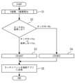
次に、使用者が液晶操作部30を的確に押圧できているかを発光部40により判別する方法を説明する。図7は、実施の形態1に係る制御回路部60の動作を示すフローチャートである。まず、ステップS1として、タッチパネルスキャン部34はタッチパネル32からの信号を読み込んで、X座標、Y座標を算出する。次に、ステップS2として、タッチパネルスキャン部34はタッチパネル32がタッチ中または長押し中であるか否かを判別する。長押し中は、予め定められた時間以上タッチパネル32がタッチされた状態が継続している状態を示す。Next, a method for determining whether the user is pressing the liquid
ステップS3として、タッチパネルスキャン部34は、タッチ中または長押し中と判別すると、発光部コントローラ41に発光部40を点灯される。タッチ中ではない場合、ステップS4として、タッチパネルスキャン部34は、発光部コントローラ41に発光部40を消灯させる。このように、発光部40は、使用者が液晶操作部30を的確に押圧できているかを表示する。本実施の形態の照明制御スイッチ20では、液晶操作部30のボタンが押されたことを発光部40の点灯状態により使用者に通知できる。従って、操作性を向上できる。In step S3, if the touch
次に、ステップS5として、タッチパネルスキャン部34は、タッチイベントを描画アプリ36に送信する。つまり、タッチパネルスキャン部34は、使用者による液晶操作部30への操作の内容を描画アプリ36に送信する。これにより、描画アプリ36および描画エンジン35は、LCDコントローラ33を介してLCD31に表示される画像を変更する。例えば、操作ボタン81aがタッチされた場合は、図4に示される操作画面81のうちタッチされた操作ボタン81aに対応する照明器具12の状態の表示が変更される。また、後述するように、操作ボタン81aが長押しされた場合、操作画面81は設定画面82に切り替わる。Next, in step S5, the touch
図8は、実施の形態1に係る照明制御スイッチ20の起動時の動作を示すフローチャートである。照明制御スイッチ20の起動時には、まずステップS11としてタッチパネル32が初期化される。ここでは、制御回路部60に記憶されたプログラムのメイン処理として、タッチパネル32およびタッチパネルスキャン部34の起動処理が行われる。次に、ステップS12としてLCD31のうちカラーLCDが初期化される。次に、ステップS13としてLCD31のうちLCDバックライトが初期化される。ステップS12、S13ではプログラムのメイン処理として、LCD31およびLCDコントローラ33の起動処理が行われる。Figure 8 is a flow chart showing the operation of the
次に、ステップS14としてアプリケーションタスクが起動する。ここでは、プログラムのメイン処理として描画アプリ36の起動処理が行われる。次に、ステップS15として、GUI(Graphical User Interface)エンジンが初期化される。ここでは、プログラムのメイン処理として描画エンジン35の起動処理が行われる。Next, in step S14, an application task is started. Here, the drawing application 36 is started as the main processing of the program. Next, in step S15, the GUI (Graphical User Interface) engine is initialized. Here, the
また、起動時において、タッチパネルスキャン部34が起動すると発光部40が点灯する。このとき、発光部40が点灯した状態で、液晶操作部30が起動しない場合は、ハードウェア層71では不具合がなく、アプリケーション層74などのソフトウェア層で不具合が生じていると特定することができる。また、発光部40が点灯せず、液晶操作部30が起動しない場合は、ハードウェア層71で不具合が生じていると特定することができる。このように、照明制御スイッチ20が発光部40を備えていることで、照明制御スイッチ20の起動時に不具合が発生した際に、不具合箇所を容易に特定することができる。Furthermore, at startup, when the touch
次に、液晶操作部30の操作ボタン81aの名称変更について説明する。図4に示される複数の操作ボタン81aには、照明器具12または複数の照明器具12からなるエリアが対応付けられている。各々の操作ボタン81aは、対応する照明器具12またはエリアの点灯状態を操作するために用いられる。使用者は操作ボタン81aを押圧することで、対応する照明器具12またはエリアに操作指令を送信することができる。Next, we will explain how to change the name of the
このような操作ボタン81aは、照明器具12またはエリアとの対応関係が分かるように名称を付けられることが望ましい。また、操作ボタン81aと照明器具12またはエリアとの対応付けは変更されることがある。このため、操作ボタン81aの名称変更が容易にできることが求められる。It is desirable that
制御回路部60は、操作ボタン81aが予め定められた時間よりも長く押されたとき、液晶操作部30に表示する画像を操作ボタン81aの名称を変更するための画像に変更する。つまり、操作ボタン81aが長押しされると、液晶操作部30の画面は、操作画面81から長押しされた操作ボタン81aの名称を変更するための設定画面82に切り替わる。設定画面82では、操作ボタン81aの名称を入力することができる。設定画面82において、文字ボタン82aを押すことで、新しい名称が入力される。入力された文字は領域82bに表示される。名称の入力後は完了ボタン82cを押すことで、名称の変更が完了する。以上から、操作ボタン81aの名称は、設定画面82で入力された名称に変更される。When the
このように、操作ボタン81aを長押しすることで、容易に名称を変更することができる。本実施の形態では、例えばメニュー画面を立上げ、複数のメニューから名称変更メニューを選択する必要がない。このように、本実施の形態では操作ボタン81aの設定の簡略化により、照明制御スイッチ20の操作性を向上できる。In this way, the name can be easily changed by pressing and holding the
また、発光部40は、操作ボタン81aが長押しされている間、発光し続ける。よって、使用者は長押しができているかを確認できる。The
長押しの操作時に連続して操作ボタン81aを押圧する時間は、例えば5秒間である。連続して操作ボタン81aを押圧する時間は、操作指令を送信するために操作ボタン81aを押圧する時間と区別が可能であれば良い。また、操作ボタン81a以外のボタンにおいても、長押しにより名称の変更ができても良い。The time for which the
また、照明制御スイッチ20は、液晶操作部30の画面を清掃し易いように清掃ロック機能を有してもよい。清掃ロック状態への移行時には、まず操作画面81において設定ボタン81bを押し、液晶操作部30の表示を図6に示されるメニュー画面83に切り替える。メニュー画面83で画面清掃モードボタン83aを押すことで、清掃ロック状態へ移行できる。The
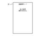
図9は、実施の形態1に係る液晶操作部30の清掃ロック時の画面の一例を示す図である。図10は、実施の形態1に係る液晶操作部30の清掃ロック時の画面の別の例を示す図である。制御回路部60は、清掃ロック状態となると、予め定められた時間だけ使用者による液晶操作部30の操作を無効とする。つまり、清掃ロック状態ではタッチパネル32からの入力が停止され、タッチパネル32を清掃時に押圧することによる誤動作を防止できる。Figure 9 is a diagram showing an example of a screen when the
清掃ロック状態では、図9、10に示されるように、液晶操作部30に画面清掃モードであること、および、清掃ロック状態の残り時間が表示される。これにより、使用者へ照明制御スイッチ20の状態を提示することができる。液晶操作部30に表示された時間が経過すると、清掃ロック状態は解除される。これにより、液晶操作部30の表示は操作画面81に切り替わる。In the cleaning locked state, as shown in Figures 9 and 10, the
また、清掃ロック状態では、照明制御スイッチ20の電源はOFFではない。このため清掃ロック状態の間に液晶操作部30以外から受信した指令がキャンセルされることはない。また、清掃ロック状態が解除された後に、照明制御スイッチ20を起動させる必要がない。In addition, in the cleaning locked state, the power supply of the
このように、照明制御スイッチ20は、液晶操作部30の清掃を容易にすることができる。従って、照明制御スイッチ20の操作性を向上できる。In this way, the
図11は、実施の形態1に係る液晶操作部30の清掃ロック時の画面93の変形例を示す図である。清掃ロック状態の残り時間が予め定められた時間となると、画面93に延長ボタン93aおよび終了ボタン93bが表示されても良い。延長ボタン93aの押下により清掃ロック状態が予め定められた時間だけ延長される。終了ボタン93bの押下により清掃ロック状態は終了する。Figure 11 is a diagram showing a modified example of the
本実施の形態では、制御回路部60は、操作ボタン81aが押されている間、発光部40を点灯させ続け、操作ボタン81aが押されていないときは発光部40を消灯状態とするものとした。これに限らず、操作ボタン81aが押されたことを発光部40の点灯状態により使用者に通知できれば良い。例えば、制御回路部60は、ボタンの長押しまたは通常の押下によらず、操作ボタン81aが押されると発光部40を点灯させても良い。また、操作ボタン81aが押されている間、発光部40は点滅し続けても良い。また、操作ボタン81aが押されていないとき、発光部40は点灯状態であり、押されているとき消灯状態となっても良い。In this embodiment, the
また、操作ボタン81a以外のボタンが押された場合に、制御回路部60はボタンが押されたことを発光部40の点灯状態により使用者に通知しても良い。操作ボタン81a以外のボタンは、設定ボタン81b、文字ボタン82a、完了ボタン82c、画面清掃モードボタン83a等である。When a button other than the
また、本実施の形態では液晶操作部30は複数の操作ボタン81aを表示するものとしたが、操作ボタン81aは1つであっても良い。また、照明制御システム100において、照明器具12は1つ以上設けられれば良い。In addition, in this embodiment, the liquid
なお、本実施の形態で説明した技術的特徴は適宜に組み合わせて用いてもよい。The technical features described in this embodiment may be used in any suitable combination.
10 設定器、11 照明コントローラ、12 照明器具、13 通信線、14 端末器、15 センサ、16 壁スイッチ、17 調光コントローラ、18 制御ユニット、19 増幅器、20 照明制御スイッチ、30 液晶操作部、32 タッチパネル、33 LCDコントローラ、34 タッチパネルスキャン部、35 描画エンジン、36 描画アプリ、40 発光部、41 発光部コントローラ、50 ケース、60 制御回路部、61 マイコン、71 ハードウェア層、72 デバイスドライバ層、73 ミドルウェア層、74 アプリケーション層、81 操作画面、81a 操作ボタン、81b 設定ボタン、82 設定画面、82a 文字ボタン、82b 領域、82c 完了ボタン、83 メニュー画面、83a 画面清掃モードボタン、93 画面、93a 延長ボタン、93b 終了ボタン、100 照明制御システム、AC 電源10 setting device, 11 lighting controller, 12 lighting fixture, 13 communication line, 14 terminal device, 15 sensor, 16 wall switch, 17 dimming controller, 18 control unit, 19 amplifier, 20 lighting control switch, 30 LCD operation unit, 32 touch panel, 33 LCD controller, 34 touch panel scan unit, 35 drawing engine, 36 drawing application, 40 light emitting unit, 41 light emitting unit controller, 50 case, 60 control circuit unit, 61 microcomputer, 71 hardware layer, 72 device driver layer, 73 middleware layer, 74 application layer, 81 operation screen, 81a operation button, 81b setting button, 82 setting screen, 82a character button, 82b area, 82c completion button, 83 menu screen, 83a screen cleaning mode button, 93 screen, 93a extension button, 93b end button, 100 Lighting control system, AC power supply
Claims (7)
Translated fromJapanese照明器具を制御するための操作ボタンを表示するタッチパネル式の液晶操作部と、
前記発光部と前記液晶操作部を制御する制御回路部と、
を備え、
前記制御回路部は、前記液晶操作部に表示されるボタンが押されたことを前記発光部の点灯状態により使用者に通知し、
前記ボタンが予め定められた時間よりも長く押されたとき、前記液晶操作部に表示する画像を前記ボタンの設定を行うための画像に変更することを特徴とする照明制御用コントローラ。 A light emitting portion;
A touch panel type liquid crystal operation unit that displays operation buttons for controlling the lighting fixtures;
A control circuit unit for controlling the light emitting unit and the liquid crystal operation unit;
Equipped with
the control circuit unit notifies a user that a button displayed on the liquid crystal operation unit has been pressed by changing the lighting state of the light emitting unit;
A lighting controller, characterized in that, when the button is pressed for longer than a predetermined time, an image displayed on the liquid crystal operation unit is changed to an image for setting the button .
照明器具を制御するための操作ボタンを表示するタッチパネル式の液晶操作部と、
前記発光部と前記液晶操作部を制御する制御回路部と、
を備え、
前記制御回路部は、前記液晶操作部に表示されるボタンが押されたことを前記発光部の点灯状態により使用者に通知し、
前記ボタンが予め定められた時間よりも長く押されたとき、前記液晶操作部に表示する画像を前記ボタンの名称を変更するための画像に変更することを特徴とする照明制御用コントローラ。A light emitting portion;
A touch panel type liquid crystal operation unit that displays operation buttons for controlling the lighting fixtures;
A control circuit unit for controlling the light emitting unit and the liquid crystal operation unit;
Equipped with
the control circuit unit notifies a user that a button displayed on the liquid crystal operation unit has been pressed by changing the lighting state of the light emitting unit;
Alighting controller characterized in that, when the button is pressed for longer than a predetermined time, an image displayed on the liquid crystal operation unit is changed to an image for changing the name of the button.
Priority Applications (1)
| Application Number | Priority Date | Filing Date | Title |
|---|---|---|---|
| JP2020207857AJP7563154B2 (en) | 2020-12-15 | 2020-12-15 | Lighting control controller |
Applications Claiming Priority (1)
| Application Number | Priority Date | Filing Date | Title |
|---|---|---|---|
| JP2020207857AJP7563154B2 (en) | 2020-12-15 | 2020-12-15 | Lighting control controller |
Publications (2)
| Publication Number | Publication Date |
|---|---|
| JP2022094775A JP2022094775A (en) | 2022-06-27 |
| JP7563154B2true JP7563154B2 (en) | 2024-10-08 |
Family
ID=82162698
Family Applications (1)
| Application Number | Title | Priority Date | Filing Date |
|---|---|---|---|
| JP2020207857AActiveJP7563154B2 (en) | 2020-12-15 | 2020-12-15 | Lighting control controller |
Country Status (1)
| Country | Link |
|---|---|
| JP (1) | JP7563154B2 (en) |
Citations (6)
| Publication number | Priority date | Publication date | Assignee | Title |
|---|---|---|---|---|
| JP2000010621A (en) | 1998-06-25 | 2000-01-14 | Matsushita Electric Works Ltd | Remote supervisory and controlling system |
| JP2004335418A (en) | 2003-05-12 | 2004-11-25 | Matsushita Electric Works Ltd | Automatic power supply on/off control device |
| JP2007258942A (en) | 2006-03-22 | 2007-10-04 | Funai Electric Co Ltd | Remote controller |
| JP2010147013A (en) | 2008-12-22 | 2010-07-01 | Toshiba Lighting & Technology Corp | Monitoring terminal unit and lighting control system |
| JP2012059580A (en) | 2010-09-09 | 2012-03-22 | Minebea Co Ltd | Switch for lighting |
| JP2019179295A (en) | 2018-03-30 | 2019-10-17 | コイズミ照明株式会社 | Input support unit and input support system |
- 2020
- 2020-12-15JPJP2020207857Apatent/JP7563154B2/enactiveActive
Patent Citations (6)
| Publication number | Priority date | Publication date | Assignee | Title |
|---|---|---|---|---|
| JP2000010621A (en) | 1998-06-25 | 2000-01-14 | Matsushita Electric Works Ltd | Remote supervisory and controlling system |
| JP2004335418A (en) | 2003-05-12 | 2004-11-25 | Matsushita Electric Works Ltd | Automatic power supply on/off control device |
| JP2007258942A (en) | 2006-03-22 | 2007-10-04 | Funai Electric Co Ltd | Remote controller |
| JP2010147013A (en) | 2008-12-22 | 2010-07-01 | Toshiba Lighting & Technology Corp | Monitoring terminal unit and lighting control system |
| JP2012059580A (en) | 2010-09-09 | 2012-03-22 | Minebea Co Ltd | Switch for lighting |
| JP2019179295A (en) | 2018-03-30 | 2019-10-17 | コイズミ照明株式会社 | Input support unit and input support system |
Also Published As
| Publication number | Publication date |
|---|---|
| JP2022094775A (en) | 2022-06-27 |
Similar Documents
| Publication | Publication Date | Title |
|---|---|---|
| JP5307227B2 (en) | Touch-type operation input device and electronic device including the same | |
| JP4943031B2 (en) | Operation panel and display control method of operation panel | |
| JP7563154B2 (en) | Lighting control controller | |
| JP3718999B2 (en) | Remote monitoring and control system | |
| JP7327966B2 (en) | Information processing device and its control method | |
| JP2008041536A (en) | Input device | |
| JP4991773B2 (en) | Supervisory control device | |
| JP2010199683A (en) | Monitoring controller | |
| JP3642505B2 (en) | Remote control device | |
| KR20050115484A (en) | Wait condition indicator and method for mobile communication terminal | |
| JP2010199900A (en) | Monitoring and control device | |
| CN114792494A (en) | Backlight control system, method, touch remote controller and computer readable storage medium | |
| JP2010147013A (en) | Monitoring terminal unit and lighting control system | |
| JP7374559B2 (en) | Air conditioning control device | |
| JP2005315512A (en) | Remote controller of water heater | |
| JPH09322269A (en) | Operating panel | |
| JP2010258699A (en) | Supervisory control device | |
| JPH11215575A (en) | Remote supervisory control system | |
| KR100346215B1 (en) | Backlight control apparatus of a wireless communication device and method thereof | |
| JP2003312103A (en) | Electronic devices and display devices for electronic devices | |
| JP2019134464A (en) | Operation device, control method, and program | |
| JPH07222675A (en) | rice cooker | |
| JP2002039610A (en) | Control device | |
| KR101328930B1 (en) | Mobile terminal having touch window unit | |
| JP2007043266A (en) | Remote controller |
Legal Events
| Date | Code | Title | Description |
|---|---|---|---|
| A621 | Written request for application examination | Free format text:JAPANESE INTERMEDIATE CODE: A621 Effective date:20230927 | |
| A977 | Report on retrieval | Free format text:JAPANESE INTERMEDIATE CODE: A971007 Effective date:20240326 | |
| A131 | Notification of reasons for refusal | Free format text:JAPANESE INTERMEDIATE CODE: A131 Effective date:20240423 | |
| A521 | Request for written amendment filed | Free format text:JAPANESE INTERMEDIATE CODE: A523 Effective date:20240530 | |
| TRDD | Decision of grant or rejection written | ||
| A01 | Written decision to grant a patent or to grant a registration (utility model) | Free format text:JAPANESE INTERMEDIATE CODE: A01 Effective date:20240827 | |
| A61 | First payment of annual fees (during grant procedure) | Free format text:JAPANESE INTERMEDIATE CODE: A61 Effective date:20240909 | |
| R150 | Certificate of patent or registration of utility model | Ref document number:7563154 Country of ref document:JP Free format text:JAPANESE INTERMEDIATE CODE: R150 |