JP7561736B2 - Automated qualitative description of anatomical changes in radiation therapy. - Google Patents
Automated qualitative description of anatomical changes in radiation therapy.Download PDFInfo
- Publication number
- JP7561736B2 JP7561736B2JP2021533231AJP2021533231AJP7561736B2JP 7561736 B2JP7561736 B2JP 7561736B2JP 2021533231 AJP2021533231 AJP 2021533231AJP 2021533231 AJP2021533231 AJP 2021533231AJP 7561736 B2JP7561736 B2JP 7561736B2
- Authority
- JP
- Japan
- Prior art keywords
- image data
- change
- anatomical image
- anatomical
- subject
- Prior art date
- Legal status (The legal status is an assumption and is not a legal conclusion. Google has not performed a legal analysis and makes no representation as to the accuracy of the status listed.)
- Active
Links
Images


Classifications
- A—HUMAN NECESSITIES
- A61—MEDICAL OR VETERINARY SCIENCE; HYGIENE
- A61N—ELECTROTHERAPY; MAGNETOTHERAPY; RADIATION THERAPY; ULTRASOUND THERAPY
- A61N5/00—Radiation therapy
- A61N5/10—X-ray therapy; Gamma-ray therapy; Particle-irradiation therapy
- A61N5/1048—Monitoring, verifying, controlling systems and methods
- A61N5/1049—Monitoring, verifying, controlling systems and methods for verifying the position of the patient with respect to the radiation beam
- A—HUMAN NECESSITIES
- A61—MEDICAL OR VETERINARY SCIENCE; HYGIENE
- A61N—ELECTROTHERAPY; MAGNETOTHERAPY; RADIATION THERAPY; ULTRASOUND THERAPY
- A61N5/00—Radiation therapy
- A61N5/10—X-ray therapy; Gamma-ray therapy; Particle-irradiation therapy
- A61N5/1048—Monitoring, verifying, controlling systems and methods
- A61N2005/1074—Details of the control system, e.g. user interfaces
Landscapes
- Health & Medical Sciences (AREA)
- Engineering & Computer Science (AREA)
- Biomedical Technology (AREA)
- Pathology (AREA)
- Nuclear Medicine, Radiotherapy & Molecular Imaging (AREA)
- Radiology & Medical Imaging (AREA)
- Life Sciences & Earth Sciences (AREA)
- Animal Behavior & Ethology (AREA)
- General Health & Medical Sciences (AREA)
- Public Health (AREA)
- Veterinary Medicine (AREA)
- Apparatus For Radiation Diagnosis (AREA)
- Radiation-Therapy Devices (AREA)
Description
Translated fromJapanese本発明は、一般に、解剖学的変化のモニタリングに関し、具体的には、本発明は、放射線治療中の被験体の解剖学的変化のモニタリングに関するが、しかしこれに限定されない。The present invention relates generally to monitoring anatomical changes, and specifically, but not exclusively, the present invention relates to monitoring anatomical changes in a subject during radiation therapy.
放射線治療において、腫瘍等の患者の身体の標的構造は放射線照射により処置される。当該放射線照射は、光子等の外部放射線や、陽子等の粒子の形で、例えば、外部ビーム放射線治療(EBRT)等で用いられる。当該治療は、標的構造(TS)に照射される放射線量が可能な限り高くなるように行われる一方で、同時に、周囲の健常な組織や構造(通常、リスク臓器(OAR)という)に照射される放射線量が可能な限り低くなるように行われる。In radiation therapy, a target structure in a patient's body, such as a tumor, is treated with radiation. The radiation can be in the form of external radiation, such as photons, or particles, such as protons, e.g., in external beam radiation therapy (EBRT). The treatment is delivered in such a way that the target structure (TS) receives as high a radiation dose as possible, while at the same time delivering as low a radiation dose as possible to the surrounding healthy tissues and structures, commonly referred to as organs at risk (OAR).
当該治療では、通常、数回に分けて患者に放射線を照射し、各回の間に回復期間が設けられる。この方法は「分割放射線治療」といい、各セッションを「フラクション」という。このアプローチには、TS腫瘍組織は、OARを含む健常組織に比べて、線量フラクションからの回復が不十分であると考えられるという推論がある。In such treatments, patients are typically exposed to radiation in separate doses with recovery periods between each dose. This method is called "fractionated radiation therapy," and each session is called a "fraction." The reasoning behind this approach is that TS tumor tissue is believed to recover less well from a dose fraction than healthy tissue, including OAR.
フラクションは1日単位で行われることが多く、処置は結果的に時間的に分散して行われる。この期間中、患者には、臓器の動きや身体に自然に起こる変形等の解剖学的変化が起きる場合がある。また、患者に提供される処置の各フラクションは、解剖学的な影響を与える場合がある。特に、放射線治療中は、腫瘍等の標的構造が縮小することが予想される。本文脈では、「放射線治療中」とは、患者が実際に放射線を浴びる特定の時点ではなく、回復期間を含むすべての治療フラクションにおいて照射が行われる全ての時間を意味する。放射線治療「中(during)」又は「中(in)」は、解剖学的変化が起こる状況を示すが、変化のモニタリングは治療フラクションの照射前又は照射後に行われ、実際のフラクションの照射中には行われない。治療中に患者に起こる解剖学的変化をモニタリングして評価し、治療が適当に行われ、必要に応じて変更や追加の措置を取りうるようにする必要がある。Fractions are often given over the course of a day, resulting in treatments that are distributed over time. During this time, the patient may undergo anatomical changes, such as organ movement and natural deformations of the body. Also, each fraction of treatment delivered to the patient may have anatomical effects. In particular, during radiation treatment, it is expected that the target structure, such as the tumor, will shrink. In this context, "during radiation treatment" does not mean the specific time at which the patient is actually exposed to radiation, but the entire time that irradiation is taking place in all treatment fractions, including recovery periods. "During" or "in" radiation treatment refers to a situation in which anatomical changes occur, but the changes are monitored before or after the delivery of a treatment fraction, not during the actual delivery of the fraction. Anatomical changes occurring in the patient during treatment need to be monitored and evaluated so that the treatment is delivered appropriately and that modifications or additional measures can be taken if necessary.
最近の放射線治療の臨床現場では、放射線治療中に患者に発生した解剖学的変化をモニタリングし、治療記録に残す。定性的記述は、当該変化の記述、伝達、記録に用いられ、定量的測定も行われる。一般に、当該変化を視覚的に評価し、手動で記録する。通常、目視検査では、定量的測定値を手動で処理し、CTスキャン等の治療計画画像と、コーンビームCT(CBCT)画像や平面X線画像、あるいは別途記録したMRI画像等の検査室内で取得した画像とを比較する。当該室内画像は、通常、治療直前に撮影され、症状モニタリングと患者の設定ともに用いられる。In modern radiotherapy clinical practice, anatomical changes occurring in patients during radiotherapy are monitored and documented in the treatment record. Qualitative descriptions are used to describe, communicate and record the changes, as well as quantitative measurements. Generally, the changes are visually assessed and recorded manually. Visual inspection usually involves manual processing of quantitative measurements and comparing treatment planning images, such as CT scans, with images acquired in the laboratory, such as cone beam computed tomography (CBCT) images, planar x-ray images, or separately recorded MRI images. The in-lab images are usually taken immediately prior to treatment and are used for both symptom monitoring and patient setup.
この視覚的評価と定量的データの分析に基づき、臨床医は解剖学的変化の種類を定性的に解釈し、説明する。しかし、視覚的な評価、手作業による処理、解釈は、エラーが発生しやすく、時間がかかる。当該エラーは、臨床医が関連する解剖学的変化を見落としたり、異なる画像中の物体間の空間的関係の解釈を誤ったりすることで発生する。また、定性的記述を手書き入力すると、類似の状況の記述にばらつきが生じ、矛盾が生じる場合がある。さらに、解剖学的変化の解釈には、大量のデータの分析と専門的熟練を要する。Based on this visual assessment and analysis of the quantitative data, clinicians qualitatively interpret and describe the types of anatomical changes. However, visual assessment, manual processing, and interpretation are error-prone and time-consuming. Such errors occur when clinicians overlook relevant anatomical changes or misinterpret the spatial relationships between objects in different images. Furthermore, handwritten input of qualitative descriptions can lead to variability and inconsistencies in the descriptions of similar situations. Furthermore, interpretation of anatomical changes requires analysis of large amounts of data and specialized skills.
本発明は、放射線治療を受けている被験体の解剖学的変化をモニタリングする自動化された方法を提供することを目的とする。本発明はさらに、治療中の被験体の解剖学的変化を矛盾なく定性的に記述する必要に対処する。The present invention aims to provide an automated method for monitoring anatomical changes in a subject undergoing radiation therapy. The present invention further addresses the need for a consistent, qualitative description of anatomical changes in a subject during treatment.
放射線治療中の被験体における解剖学的変化をモニタリングするシステム及び方法並びに医用撮像及び分析用の配置及び当該方法を実行するコンピュータプログラムが提供される。放射線治療中の被験体の解剖学的変化をモニタリングするシステムは、前記被験体の第1の解剖学的画像データ及び後続の解剖学的画像データを受信するように構成される入力を備える、分析ユニットを含み、前記分析ユニットは、少なくとも前記後続の解剖学的データを前記第1の解剖学的データに登録するように構成される。当該システムは、さらに、前記第1の解剖学的画像データと前記後続の解剖学的画像データとの間の変化を変化状態として識別するように構成される変化状態識別ユニット及び前記識別された変化状態を対応する定性的記述に一致させるように構成される定性的トランスレータを含む。変化状態とは、変化がその特徴に応じてグループ化された、特定の複数の分類である。第1の解剖学的画像データと後続の解剖学的画像データとの間の変化の特性に最も対応する分類を割り当てることにより、変化状態が識別される。好ましくは、当該定性的記述は、変化状態の特徴を示す。より好ましくは、当該定性的記述は、治療中の患者をモニタリングする際に、医師が変化の特徴をどのように説明するかを反映する。当該システムは、さらに、前記識別された変化状態の定性的記述を含むモニタリングレポートを提供するように構成される報告ユニットを備える。当該対応する定性的記述は、例えば、自然言語記述及び/又はグラフィック画像、好ましくは絵表示(pictogram)である。絵表示は、臨床医だけでなく、患者や他分野の医師にも理解しやすいという利点がある。A system and method for monitoring anatomical changes in a subject during radiation therapy, as well as an arrangement for medical imaging and analysis and a computer program for carrying out the method, are provided. The system for monitoring anatomical changes in a subject during radiation therapy includes an analysis unit having an input configured to receive first anatomical image data and subsequent anatomical image data of the subject, the analysis unit being configured to register at least the subsequent anatomical data to the first anatomical data. The system further includes a change state identification unit configured to identify changes between the first anatomical image data and the subsequent anatomical image data as change states, and a qualitative translator configured to match the identified change states to corresponding qualitative descriptions. A change state is a specific plurality of classifications in which changes are grouped according to their characteristics. A change state is identified by assigning a classification that best corresponds to the characteristics of the change between the first anatomical image data and the subsequent anatomical image data. Preferably, the qualitative description is indicative of the characteristics of the change state. More preferably, the qualitative description reflects how a physician would describe the characteristics of the change when monitoring a patient during treatment. The system further comprises a reporting unit configured to provide a monitoring report including a qualitative description of the identified altered state. The corresponding qualitative description may be, for example, a natural language description and/or a graphic image, preferably a pictogram. A pictogram has the advantage that it is easy to understand not only for clinicians, but also for patients and physicians of other disciplines.
当該システムの実施形態では、当該変化状態識別ユニットは、少なくとも1つの定性的空間推論アルゴリズムを含み、前記定性的空間推論アルゴリズムは、好ましくは、RCC-8計算(計算)アルゴリズム及び/又はカーディナル空間推論アルゴリズムである。In an embodiment of the system, the change state identification unit includes at least one qualitative spatial reasoning algorithm, which is preferably an RCC-8 computational (calculation) algorithm and/or a Cardinal spatial reasoning algorithm.
好ましくは、当該システムの前記分析ユニットは、さらに、前記被験体の治療計画の線量分布データを受信するように構成される入力を含み、並びに、前記変化状態識別ユニットは、さらに又はあるいは前記線量分布データと後続の解剖学的画像データとの間の変化を変化状態として識別するように構成される。場合によっては、この選択肢の入力を含めることで、当該システムは、計画された線量分布と比較して、当該被験体の解剖学的変化をさらに又はあるいはモニタリングすることができる。Preferably, the analysis unit of the system further includes an input configured to receive dose distribution data of the treatment plan for the subject, and the change state identification unit is further or alternatively configured to identify a change between the dose distribution data and subsequent anatomical image data as a change state. In some cases, including this optional input allows the system to further or alternatively monitor anatomical changes of the subject compared to the planned dose distribution.
好ましくは、前記定性的トランスレータは、ルックアップテーブルを用いて、前記識別された変化状態を前記対応する定性的記述に一致させるように構成される。Preferably, the qualitative translator is configured to match the identified change states to the corresponding qualitative descriptions using a lookup table.
好ましくは、前記報告ユニットは、前記モニタリングレポートを視覚的に表示するように構成されるディスプレイを含む。これは、当該モニタリングレポートが絵表示レポートである場合、特に好ましい。具体的には、前記ディスプレイは、前記モニタリングレポートをグラフィカルユーザインタフェースの形態で視覚的に表示するように構成される点で有利である。当該報告をユーザインタフェースの形態で表す利点は、状況に応じて、当該報告のバージョンが当該状況に最適であるように選択し、かつ表示できる点である。さらに、例えば、患者の画像、線量情報、分析結果の定量的データ等の追加データをバックグラウンドで利用でき、必要に応じて選択し、かつ表示できるという利点もある。選択されない場合は情報が表示されないため、レポートのメイン画面が簡素化され、理解しやすくなる。好ましくは、グラフィカルユーザインタフェースは、前記モニタリングレポートの部分として表示される情報を選択する、少なくとも1つのコントロールを備え、当該選択肢を最適に利用する。Preferably, the reporting unit includes a display configured to visually display the monitoring report. This is particularly preferred when the monitoring report is a pictorial report. In particular, the display is advantageously configured to visually display the monitoring report in the form of a graphical user interface. The advantage of presenting the report in the form of a user interface is that depending on the situation, a version of the report can be selected and displayed that is optimal for the situation. It also has the advantage that additional data, e.g. patient images, dose information, quantitative data of the analysis results, etc., are available in the background and can be selected and displayed as required. The main report screen is simplified and easier to understand, since no information is displayed if not selected. Preferably, the graphical user interface comprises at least one control to select the information to be displayed as part of the monitoring report, making optimal use of said options.
放射線治療中の被験体における解剖学的変化をモニタリングする方法は、前記被験体の第1の解剖学的画像データ及び後続の解剖学的画像データを受信する工程、及び前記第1の解剖学的画像データ及び前記後続の解剖学的画像データを解析する工程であって、前記解析には、前記後続の解剖学的データを前記第1の解剖学的データに登録することを含む、工程を含む。当該方法は、さらに、前記第1の解剖学的画像データと前記後続の解剖学的画像データとの間の変化を変化状態として識別する工程、及び前記識別された変化状態を対応する定性的記述に一致させる工程を含む。当該方法はまた、前記識別された変化の定性的記述を含むモニタリングレポートを提供する工程を含む。当該方法は、好ましくは、コンピュータで実行される。A method for monitoring anatomical changes in a subject undergoing radiation therapy includes receiving first and subsequent anatomical image data of the subject, and analyzing the first and subsequent anatomical image data, the analysis including registering the subsequent anatomical data to the first anatomical data. The method further includes identifying changes between the first and subsequent anatomical image data as change conditions, and matching the identified change conditions to corresponding qualitative descriptions. The method also includes providing a monitoring report including the qualitative descriptions of the identified changes. The method is preferably computer-implemented.
当該方法の好ましい実施形態では、前記変化を識別する工程は、前記第1の解剖学的画像データ及び前記後続の解剖学的画像データを少なくとも1つの定性的空間推論アルゴリズムに供給する工程を含み、ここで、前記定性的空間推論アルゴリズムは、好ましくは、RCC-8計算アルゴリズム及び/又はカーディナル空間推論アルゴリズムである。In a preferred embodiment of the method, identifying the change includes providing the first anatomical image data and the subsequent anatomical image data to at least one qualitative spatial reasoning algorithm, where the qualitative spatial reasoning algorithm is preferably an RCC-8 computational algorithm and/or a Cardinal spatial reasoning algorithm.
好ましくは、前記被験体の前記第1及び後続の解剖学的画像データを受信する工程は、さらに、前記被験体の治療計画の線量分布データを受信する工程を含み、かつ、前記変化を識別する工程は、さらに又はあるいは、前記線量分布データと後続の解剖学的画像データとの間の変化を変化状態として識別する工程を含む。Preferably, the step of receiving the first and subsequent anatomical image data of the subject further includes a step of receiving dose distribution data of a treatment plan for the subject, and the step of identifying the change further or alternatively includes a step of identifying a change between the dose distribution data and the subsequent anatomical image data as a change condition.
他の好ましい実施形態では、他の実施形態や好適に組み合わせてよく、前記解剖学的画像データを分析する工程は、さらに、定量的画像データを獲得する工程を含み、ここで、前記画像データは、好ましくは、関心領域のサイズ、関心領域のサイズ変化、関心領域がシフトした距離、関心領域が受けた総放射線量、の少なくとも1つを含む。定量的画像データが獲得された場合、前記モニタリングレポートは、好ましくはまた、少なくとも1つの前記識別された変化の少なくとも1つの定量的記述を含む。In other preferred embodiments, which may be combined with other embodiments as appropriate, analyzing the anatomical image data further comprises acquiring quantitative image data, where the image data preferably comprises at least one of the following: a size of the region of interest, a change in size of the region of interest, a distance the region of interest has shifted, and a total radiation dose received by the region of interest. If quantitative image data is acquired, the monitoring report preferably also comprises at least one quantitative description of at least one of the identified changes.
医用画像処理及び分析用の配置は、処置される被験体の画像を供給するように構成される、1又はそれ以上の撮像装置、前記1又はそれ以上の撮像装置により供給される画像に基づく、解剖学的画像データを供給するように構成される、輪郭形成ツール、及び;放射線治療中の被験体における解剖学的変化をモニタリングするための、放射線治療中の解剖学的変化をモニタリングする上記システムを備える。The medical image processing and analysis arrangement comprises one or more imaging devices configured to provide images of a subject being treated, a contouring tool configured to provide anatomical image data based on images provided by the one or more imaging devices, and; the above-mentioned system for monitoring anatomical changes during radiation therapy for monitoring anatomical changes in the subject during radiation therapy.
本発明の利点は、放射線治療を受けている患者の解剖学的変化が、より迅速にかつより正確にモニタリングしうることである。当該変化の変化状態としての識別により、変化を矛盾なく分類することができる。前記第1及び後続の画像の自動解析は、当該変化の自動識別と組み合わせると、臨床医により当該画像の手作業による比較よりも、より迅速かつより正確である。An advantage of the present invention is that anatomical changes in patients undergoing radiation therapy may be monitored more quickly and more accurately. Identification of the changes as a change state allows the changes to be consistently classified. The automated analysis of the first and subsequent images, combined with the automated identification of the changes, is faster and more accurate than manual comparison of the images by a clinician.
本発明の他の利点は、放射線治療を受けている患者の解剖学的変化をより着実にモニタリングできることである。当該変化を変化状態として識別することで、変化を矛盾なく分類することができる。また、各変化状態は、対応する定性的記述と一致される。その結果、同じ分類に属する変化の定性的記述は同じである。これには、医師や臨床医がデータベースの中から類似のケースを見つけやすくなるというさらなる利点がある。また、機械学習アルゴリズムの入力としてデータセットを用いうるという利点もある。Another advantage of the present invention is that it allows for more robust monitoring of anatomical changes in patients undergoing radiation therapy. By identifying the changes as change states, the changes can be consistently classified. Each change state is also matched with a corresponding qualitative description. As a result, changes that belong to the same classification have the same qualitative description. This has the added advantage of making it easier for doctors and clinicians to find similar cases in a database. Another advantage is that the dataset can be used as input for machine learning algorithms.
さらなる利点は、さらなる分析を必要とせずに、変化を直接知ることができるモニタリングレポートが提示される点にある。当該変化は、例えば、医師が患者の症状を説明するのに用いるのと同様の言語を用いる等、定性的な方法で報告されるので、データを広範に説明しなくても、報告書を患者又は相談役の医師に読んでもらうか、又は見てもらうことで、情報提供ができる。An additional advantage is that monitoring reports are presented that allow changes to be noted directly without the need for further analysis. The changes are reported in a qualitative manner, for example using language similar to that used by doctors to describe patients' symptoms, so that the reports can be read or viewed by the patient or consulting doctor to provide information without extensive explanation of the data.
記載された発明からのさらなる利点もまた、当業者には明らかであろう。Further advantages from the described invention will also be apparent to those skilled in the art.
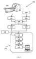
図1は、放射線治療中の被験体における解剖学的変化をモニタリングするシステム110を例示する。この例では、当該システムは、医用撮像及び分析用の配置100の部分として例示される。FIG. 1 illustrates a
医用画像処理及び分析用の配置100では、画像処理装置102により治療を受ける当該被験体の計画画像101が取得される。この画像は、コンピュータ・トモグラフィー画像(CT)、磁気共鳴画像(MR)、ポジトロン・エミッション・トモグラフィー(PET)他の医用画像、又は、PET/CTやPET/MRを組み合わせた画像等の複合画像であってよい。図1では、一例として、PET/CT撮像装置102が例示される。この第1の画像において、輪郭形成ツール103を用いて関心領域(ROI)を画定し、第1の解剖学的画像データ104を提供する。被験体内のROIは、少なくとも1つの標的構造(TS)、通常は腫瘍か、1又はそれ以上の複数のリスク臓器(OAR)を含むであろう。輪郭形成ツールは、一般に、例えば訓練を受けた医用画像処理技術者や放射線科医であることができるユーザと対話して、ROIの輪郭を定義する。このプロセスは、完全に手動で行うこともできるし、一部又は全部を自動化することもできる。In the medical imaging and
治療の過程で、当該被験体の少なくとも1つの後続の画像105が取得される。この画像は、当該計画画像と同じ撮像装置102を用いて取得することができるが、1又はそれ以上の代替撮像装置106を用いて取得することもできる。このような代替撮像装置は、CT、MR又は他の医用撮像装置であってよい。好ましい実施形態では、当該後続の画像は、治療室で当該被験体を撮像するように構成されるコーンビームCT(CBCT)又は平面X線撮像装置のいずれかである第2の医用撮像装置106を用いて取得される。この設定の利点は、当該画像を、当該被験体の解剖学的変化のモニタリングや、放射線療法治療フラクションの照射のための当該被験体の設定に用いることができることである。During the course of treatment, at least one
当該後続の画像105では、ROIはまた輪郭形成ツール103を用いて画定されて、後続の解剖学的画像データ107を提供する。輪郭形成は、当該計画画像のようにゼロから、手動で、自動で、又は半自動で、ユーザインタラクションを用いて行うことができる。また、当該その後続の画像の輪郭形成は、変形可能な画像登録のプロセスを用いて、計画画像101から後続の画像105に輪郭を自動的に伝播させることによって行うこともできる。このプロセスを用いる場合、ユーザには、好ましくは、自動的に伝播された輪郭を承認及び/又は手動で修正する選択肢がある。In the
次に、解剖学的画像データ104及び107を分析して、当該被験体の解剖学的変化をモニタリングする。これは、放射線治療における解剖学的変化をモニタリングするシステム110を用いて行われる。当該システムは、分析ユニット111、変化状態識別ユニット112、定性的トランスレータ113及び報告ユニット114を含む。当該分析ユニット111は、当該被験体の第1の解剖学的画像データ104及び後続の解剖学的画像データ107を受信するように構成される入力を備える。The
分析ユニット111は、少なくとも、後続の解剖学的画像データ107を第1の解剖学的画像データ104に登録するように構成される。上記のように、第1の計画画像101は、後続の画像105の取得に用いられる装置106とは異なる撮像装置102を用いて取得されてよい。また、撮像装置における被験体の位置は、画像の取得ごとに少しずつ変化する。その結果、解剖学的画像データの基準となるフレームは、スケールと同様に画像ごとに異なる場合がある。しかし、正確で信頼性の高い比較を行うためには、第1の解剖学的画像104データと後続の解剖学的画像データ107の参照フレームはともに同じであることが望ましい。画像が取得された状況ではなく、被験体の解剖学的構造の変化に起因する変化が検出されるためには、画像のサイズは同じスケールであり、座標系が同じであることが望ましい。そのため、後続の画像とその解剖学的画像データのスケール及び参照フレームを、第1の解剖学的画像とその解剖学的画像データのそれらに一致させる必要がある。この一致させる作業を「登録」という。後続の解剖学的画像データを第1の解剖学的画像データに登録することは、解剖学的ランドマークを識別して一致させることによって行うことができる。解剖学的ランドマークは、例えば骨の構造等、放射線治療の時間枠内ではほとんど変化しないことが知られている被験体の解剖学的構造である。解剖学的ランドマークは、輪郭の形で解剖学的画像データの一部とすることができ、例えば、画像の一部である骨構造の輪郭である。その後、後続の解剖学的画像データは、解剖学的ランドマークのサイズ及び位置が、第1の解剖学的画像データにおける解剖学的ランドマークのサイズおよび位置に可能な限り密接に対応するまで、スケーリング、翻訳、及び回転される。好ましくは、当該登録は自動化される。The
分析ユニット111は、さらに、第1の解剖学的画像データと第2の解剖学的画像データとの間の解剖学的変化を定量化するように構成されてよい。この定量化は、例えば、OARのシフトの大きさをミリメートル単位で示す等、絶対的であってよい。当該定量化はまた、例えば、TSが縮小した比率等のように相対的であってよい。特に、分析ユニット111は、さらに、図4を参照して後述するいかなる追加解析方法工程を実行するように構成されてよい。The
変化状態識別ユニット112は、第1の解剖学的画像データ104と後続の解剖学的画像データ107との間の変化を変化状態として識別するように構成される。変化状態とは、変化がその特徴に応じてグループ化された、所定の複数の分類である。第1の解剖学的画像データと後続の解剖学的画像データとの間の変化の特性に最も対応する分類を割り当てることによって、変化状態が識別される。当該変化状態は、ユーザが事前に定義した特性を備える分類や、空間モデルやサイズモデルに基づいてよい。空間モデルでは、2つの領域間の可能な関係に応じて変化状態を定義する。当該モデルの変化状態の数と性質は、関心のある特性に依存する。当該モデル、又は当該変化状態の識別に用いられるモデルは、それに応じて選択することができる。The change
例えば、ROIのシフトが注目すべき特性である場合がある。この場合、変化はシフトの大きさや方向により分類又はモデル化される。方向のモデルとしては、コンパスの方向がよく知られており、北、南、東、西の4つの変化状態が定義される。シフトのサイズは、ユーザが定義した範囲、例えば、3つの変化状態(小、中、大)の定義、を用いて分類することができる。他の例では、ROIの元の位置との重なりが注目される。単純な重なりモデルでは、4つの変化状態(完全な重なり、部分的な重なり、接触、重なりなし)を定義する。さらに他の例では、ROIのサイズの変化が注目すべき特性である場合がある。この例では、単純なモデルにより、3つの変化状態(成長、収縮、変化なし)が定義される。For example, a shift in the ROI may be a feature of interest. In this case, the change is classified or modeled according to the magnitude and direction of the shift. A well-known model of direction is the compass direction, which defines four change states: north, south, east, and west. The size of the shift may be classified using a user-defined range, for example, defining three change states (small, medium, and large). In another example, the overlap of the ROI with its original position is of interest. A simple overlap model defines four change states (full overlap, partial overlap, touching, and no overlap). In yet another example, a change in the size of the ROI may be of interest. In this example, a simple model defines three change states (growth, shrinkage, and no change).
定性的トランスレータ113は、変化状態識別ユニット112により識別された変化状態を、対応する定性的記述に一致させるように構成される。好ましくは、当該定性的記述は、変化状態の特性の表示を提供する。例えば、「OARが左にシフトしている」又は「TSが縮小している」である。より好ましくは、当該定性的記述は、治療中の患者をモニタリングする場合、医師が変化の特徴をどのように説明するかを反映する。定性的トランスレータ113は、好ましくは、ルックアップテーブルを用いて、識別された変化状態を対応する定性的記述に一致させるように構成される。ルックアップテーブルは、変化状態が検出された場合、各変化状態に対して同じ定性的記述を一貫して用いる簡便な方法を提供する。The
報告ユニット114は、識別された変化状態の定性的記述を含むモニタリングレポートを提供するように構成される。図1の例では、当該報告ユニットは、モニタリングレポートを視覚的に表示するディスプレイ115を備える。好ましい実施形態では、モニタリングレポートは、例えば、図6に例示されるグラフィカルユーザインタフェースの形態で表示される。The
図1に例示された例示的な実施形態では、解剖学的変化110をモニタリングするシステムの分析ユニット111は、被験体の治療計画の線量分布データ108を受信する入力をさらに備える。これは、解剖学的画像データを受信するように構成されるのと同じ入力や、他の入力であってよい。当該線量分布データは、好ましくは、例えばアイソドーズコンターの形で、分画された線量領域を含む。In the exemplary embodiment illustrated in FIG. 1, the
当該分画線量領域は、第1の解剖学的画像データ104の代わりに、計画された線量に関する被験体における被験体の解剖学的変化をモニタリングするシステムにより用いられうる。このため、変化状態識別ユニット112は、さらに、線量分布データ108及び後続の解剖学的画像データ107との間の変化を変化状態として識別するように構成されるのが好ましい。この選択肢が含まれることにより、当該システムは、計画された線量分布と比較して、当該被験体における解剖学的変化をさらに又はあるいはモニタリングすることができる。The fractionated dose area can be used by the system to monitor anatomical changes in the subject with respect to the planned dose instead of the first
モニタリングシステム110の一実施形態では、変化状態識別ユニット112は、少なくとも1つの定性的空間推論アルゴリズムを含み、この定性的空間推論アルゴリズムは、好ましくは、RCC-8計算アルゴリズム及び/又はカーディナル空間推論アルゴリズムである。定性的空間推論は、類似の定量的測定値を要約した定性的記述を生成する問題を扱う人工知能の一分野である。In one embodiment of the
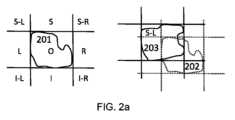
図2a及び2bは、定性的空間推論アルゴリズムによる変化状態の検出を概略的かつ例示的に示す。Figures 2a and 2b show a schematic and exemplary depiction of change state detection by a qualitative spatial reasoning algorithm.
図2aは、2つのオブジェクト間のカーディナル方向関係の形態の変化状態の検出を例示する。当該例示は、2Dカーディナル空間推論用であるが、この形式のモデル化は3Dでも用いられうる。3Dカーディナル定性的空間推論は、ROIのシフトを検出し、定性的に記述するのに特に適する。Figure 2a illustrates the detection of a change in the form of a cardinal directional relationship between two objects. The illustration is for 2D cardinal spatial reasoning, but this form of modeling can also be used in 3D. 3D cardinal qualitative spatial reasoning is particularly suitable for detecting and qualitatively describing shifts in an ROI.
図2aの左側に示すように、比較の基礎を形成するROI 201は、周囲に方向性グリッドが定義される境界ボックスに適合される。当該方向性グリッドは可能なシフト状態のモデルを形成する。このモデルは2D用には上下左右に、9つの変化状態、すなわち、S-Lは上方と左、Lは左、I-Lは下方と左、Sは上方、0は上方、Iは下方、S-Rは上方と右、Rは右、I-Rは下方と右、がある。As shown on the left side of Fig. 2a, the
図2aの右側は、ROIの変化状態の検出を示す。第1の解剖学的画像データ202のROIは、点線の輪郭とグリッドで示され、同じROIは、後続の解剖学的画像データ203に実線の輪郭と境界ボックスで示される。識別された変化状態は、「ROIが上方及び左方にシフトした」という自然言語の形式に対応する「S-L」という定性的記述である。The right side of FIG. 2a illustrates the detection of a change state of the ROI. The ROI in the first
図2(b)は、RCC-8計算によって同定される変化状態を示す。RCC-8計算は領域結合計算の一種である。RCC-8計算は、2つの領域の関係を8つの可能な空間的関係にモデル化し、変化状態を形成する。RCC-8計算は、単一のROIの変化を記述するのに用いることができるが、治療計画の線量分布の高線量領域とTSとOARの位置と重なりを記述するのに特に適する。RCC-8計算は、TSとOARが重複している場合や近接している場合の変化の記述にも役立つ。Figure 2(b) shows the change states identified by the RCC-8 calculation. The RCC-8 calculation is a type of region coupling calculation. The RCC-8 calculation models the relationship between two regions into eight possible spatial relationships to form the change states. The RCC-8 calculation can be used to describe the changes in a single ROI, but is particularly suited to describing the high dose regions of the dose distribution in a treatment plan and the location and overlap of the TS and OAR. The RCC-8 calculation is also useful for describing the changes when the TS and OAR overlap or are in close proximity.
RCC-8計算モデルの変化状態は、図2bにおいて、上から下、左から右へ、つまり、非接触DC、部分的重複PO、外部接触EC、等価EQ、接線適正部分TPP、接線適正逆部分TPPi、非接線適正部分NTPP、及び非接線適正部分NTPPiである。The changing states of the RCC-8 computational model are, from top to bottom and left to right in Figure 2b, non-contact DC, partial overlap PO, external contact EC, equivalent EQ, tangent proper part TPP, tangent proper inverse part TPPi, non-tangent proper part NTPP, and non-tangent proper part NTPPi.
図2(b)は、ROI AとROI Bの変化状態を例示する。これらは同じROIであってよく、第1の解剖学的画像データはA、後続の解剖学的画像データはBとして用いられる。例えば、変化状態「A NTPpi B」が識別された場合、自然言語「ROIが縮小した」形態の対応する定性的記述があってよい。あるいは、例えば、変化状態「A DC B」が識別された場合、ROIの自然言語は「ROIが完全に元の位置から外れた」であってよい。あるいは、ROIが線量計画データであり、ROI Bが後続画像のROIであってよい。例えば、変化状態「A NTTPi B」が識別された場合、自然言語は「ROIが高線量治療領域に入る」であってよい。さらに、AとBは同じ解剖学的画像データの中で2つの異なるROIである場合もある。例えば、変化状態「A PO B」が検出された場合、対応する自然言語は、「OARがTSと重複する」である場合もある。FIG. 2(b) illustrates the change states of ROI A and ROI B. These may be the same ROI, with the first anatomical image data used as A and the subsequent anatomical image data used as B. For example, if the change state "A NTPpi B" is identified, there may be a corresponding qualitative description in the form of natural language "ROI has shrunk". Alternatively, for example, if the change state "A DC B" is identified, the natural language of the ROI may be "ROI has completely moved out of its original position". Alternatively, the ROI may be the dose planning data and ROI B may be the ROI of the subsequent image. For example, if the change state "A NTPi B" is identified, the natural language may be "ROI enters the high dose treatment region". Furthermore, A and B may be two different ROIs in the same anatomical image data. For example, if a change state "A PO B" is detected, the corresponding natural language might be "OAR overlaps with TS."
被験体の解剖学的構造に変化がなく、1又はそれ以上のROIが第1の解剖学的画像データと後続の解剖学的画像データで実質的に同一である場合も、変化状態として識別される。この状態に一致する定性的記述例は「ROIの変化なし」であり、図2aでは「O」、図2bでは「EQ」として検出される。A change condition is also identified when there is no change in the subject's anatomical structure and one or more ROIs are substantially identical in the first and subsequent anatomical image data. An example qualitative description consistent with this condition is "no change in ROIs," which is detected as "O" in FIG. 2a and "EQ" in FIG. 2b.
図3は、被験体放射線療法300における解剖学的変化をモニタリングする方法の工程を概略的に例示する。被験体における解剖学的変化をモニタリングする方法は、第1の解剖学的画像データ301及び後続の解剖学的データ302を得る工程が先行する。この解剖学的画像データは、図1に示す医用画像分析の配置100に関して上記と同様の方法で得ることができる。Figure 3 illustrates diagrammatically the steps of a method for monitoring anatomical changes in a subject during
本発明による放射線療法における被験体の解剖学的変化をモニタリングする方法300は、被験体の第1の解剖学的画像データ及び後続の解剖学的画像データを受信する工程310と、第1の解剖学的画像データ及び後の解剖学的画像データを分析する工程320とを含み、当該分析工程は、後続の解剖学的データを第1の解剖学的データに登録する工程を含む。本方法はさらに、第1の解剖学的画像データと後続の解剖学的画像データとの間の変化を変化状態として識別する工程330と、識別された変化状態を対応する定性的記述に一致させる工程340とを含む。この方法はまた、識別された変化の定性的記述を含むモニタリングレポートを提供する工程350を含む。The
図4は、放射線療法における被験体における解剖学的変化をモニタリングする方法400の他の例の工程を概略的に例示する。図4の方法400は、図3に示される方法300の工程310、320、340及び350に類似する方法工程410、420、440及び450を含む。しかしながら、図4の方法工程は、図3の方法300と比較して複数の追加選択肢を含み、これらの工程は、図4に例示するように、別々に、サブコンビネーションで、又は完全に組み合わせて用いることができる有利な追加選択肢を表す。Figure 4 illustrates in a schematic manner the steps of another
有利には、図1に例示された解剖学的変化をモニタリングするシステム110は、さらに、これらの追加の工程のいずれか又は全てを実行するように構成されてよい。Advantageously, the
被験体における解剖学的変化をモニタリングする方法は、第1の解剖学的画像データ301及び後続の解剖学的データ302を得る工程が先行する。また、この方法の前に、線量分布データ401を含む被験体の治療計画が決定される。The method of monitoring anatomical changes in a subject is preceded by obtaining first
本発明による放射線療法における被験体の解剖学的変化をモニタリングする方法400は、データを受信する工程410を含む。当該データ受信工程410は、被験体の第1の解剖学的画像データ及び後続の解剖学的画像データを受信する工程を含み、さらに、被験体の治療計画の線量分布データを受信する工程を含む。The
この方法は、次に、受信されたデータを分析する工程420を含む。当該データ分析工程は、後続の解剖学的データを第1の解剖学的データに登録する工程421を含む。図4に示す例示的な実施形態では、解剖学的画像データを分析する工程は、定量的画像データを得る工程をさらに含む。定量的データの取得は、ROIのサイズ又は体積の測定422、ROIのサイズ又は体積の変化423、ROIがシフトした距離424、及び/又はROIの放射線量425のうちの1又はそれ以上を含んでよい。当該ROIは、1又はそれ以上のOAR及び/又は1又はそれ以上のTSであってよい。当該ROIの変化について定量的データが得られる場合は変化の絶対値で表すことができるが、相対値、例えばパーセントで表すこともできる。The method then includes analyzing 420 the received data. The data analysis includes registering 421 subsequent anatomical data to the first anatomical data. In the exemplary embodiment shown in FIG. 4, analyzing the anatomical image data further includes obtaining quantitative image data. Obtaining the quantitative data may include one or more of a measurement of a size or volume of the
この方法は、さらに、受信データの変化を変化状態として識別する工程430を含む。変化は、第1の解剖学的画像データと後続の解剖学的画像データとの間で識別され(431)、かつ、さらに又はあるいは、線量分布データと後続の解剖学的画像データとの間で識別される(432)。両工程では、第1の解剖学的画像データ又は線量分布データのいずれか及び後続の解剖学的画像データが、1又はそれ以上の空間推論アルゴリズムに供給されるのが好ましい。The method further includes a
図4の例示的実施形態のモニタリング方法は、患者の危険因子426を決定するいかなる工程を含む。ROIが受信した線量に関する定量的情報は、好ましくは、治療の各フラクションの送達後にさらなる参照のために計算され、保存される。当該情報としては、線量体積ヒストグラム、ROIの中の線量分布、又はROIの全領域によって受信される平均線量又は総線量があげられうる。この定量的線量情報を計算し保存することには、ROIがそれまでに受けた線量を、後続の画像データに基づいて次のフラクションで照射されるであろう予想線量と組み合わせることができるという利点がある。臨床現場では、ROIは安全と考えられる、受信した放射線の1つ又は複数の統計的記述子の許容限度をあらかじめ定める。これらの統計的記述子は、とりわけ、線量体積ヒストグラム、ROI領域全体に対する最小線量、ROI領域全体に対する最大線量、ROIの最も高温の部分領域に対する最大線量、平均線量、又は平均の最大又は最小線量であり得る。適当な統計的記述子は、ROIの性質により決定される。例えば、TSの場合、少なくとも最小線量がTS領域全体に投与されるように処方される。また、例えば、OARの場合、平均線量がある閾値を超えてはならないように処方されることもある。ROIについて計算された1又はそれ以上の統計的記述子の値が所定の許容限度内にある場合、危険因子は低いと判定される。1又はそれ以上の統計的記述子の値が許容限度を下回っているが、この値に近接する場合、リスクは中程度と判定される。ROIの統計的記述子の値が、次のフラクションの許容レベルを超える場合、リスクは高いと判断される。The monitoring method of the exemplary embodiment of FIG. 4 includes any step of determining patient risk factors 426. Quantitative information regarding the dose received by the ROI is preferably calculated and stored for further reference after the delivery of each fraction of the treatment. Such information may include a dose volume histogram, a dose distribution within the ROI, or an average or total dose received by the entire region of the ROI. Calculating and storing this quantitative dose information has the advantage that the dose received by the ROI so far can be combined with the expected dose that will be delivered in the next fraction based on subsequent image data. In clinical practice, the ROI predefines the acceptable limits of one or more statistical descriptors of the received radiation that are considered safe. These statistical descriptors may be, among others, a dose volume histogram, a minimum dose for the entire ROI region, a maximum dose for the entire ROI region, a maximum dose for the hottest subregion of the ROI, an average dose, or an average maximum or minimum dose. The appropriate statistical descriptor is determined by the nature of the ROI. For example, in the case of TS, at least a minimum dose is prescribed to be administered to the entire TS region. Also, for example, in the case of OAR, the average dose may be prescribed not to exceed a certain threshold. If the value of one or more statistical descriptors calculated for the ROI is within a predefined tolerance limit, the risk is determined to be low. If the value of one or more statistical descriptors is below the tolerance limit but close to this value, the risk is determined to be medium. If the value of the statistical descriptor of the ROI exceeds the tolerance level of the next fraction, the risk is determined to be high.
この方法の工程440では、当該分析及び識別された変化状態から得られた定量的データ、並びに識別された危険因子が収集され、組み合わされる。識別された変化を、対応する説明と一致させる。この工程は、識別された変化状態を対応する定性的記述441に一致させる工程を含む。定性的記述は、該当する場合、定量的データ442、及び特定された危険因子443によって補足することができる。好ましくは、定量的データは、識別された変化の定性的な自然言語記述、例えば、「腫瘍TSが10%縮小した」、又は「臓器OARが5mm左方に高線量領域にシフトした」等の補足に用いられ、426で測定された危険因子は、例えば、「高」、「中」、「低」として別個に示すこともできるが、好ましくは、例えば、赤は高、黄は中及び緑は低といったカラーコーディング形式の絵表示による定性的記述である。定量的データを絵表示情報の補足に用いて、例えば、絵表示要素の相対的な大きさを示すこともできる。In
工程444では、収集され、かつ結合されるデータが、さらに、現在の患者の状態が医師によるレビュー及び追跡が必要か否かの識別に用いられる。例えば、TSが治療計画の高線量領域を大きく外れた場合、治療計画の修正が必要かもしれない。他の例では、OARは、患者を安定させ、及び/又は治療の有害な副作用を軽減するのに追加の手段が必要な程度に縮小した場合がある。In
この方法はまた、識別された変化の定性的記述を含むモニタリングレポートを提供する工程450を含む。この実施形態では、医師にレビューするように警告するため、定量的情報は、工程444で識別されたいかなるフォローアップ及び報告に含まれる。The method also includes
図5は、絵表示レポートの形式の被験体における解剖学的変化のモニタリングレポート500の例を概略的に例示する。当該レポートは、好ましくはディスプレイ上に提示される。しかしながら、治療を受けている患者への情報の配布が容易であるハードコピー印刷も可能である。この例では、モニタリングレポート500は、表形式で提示される。表の行は、モニタリングされる関心領域である。この実施例では、関心領域は、治療領域に位置する2つのOAR、OAR1及びOAR2、並びに腫瘍GTVの形態のTSである。当該関心領域は、例えば、OARとしての左耳下腺及び左耳下腺に近接して位置する腫瘍の形態のTSであり得る。列は、治療のフラクションの送達前の患者の状態を表す。F1列はフラクション1、F2はフラクション2などである。例示された報告は、フラクション5のF5まで提供される。当該例における解剖学的変化は、治療計画の線量分布に関して分析され、報告される。線量分布データは、計画された標的体積PTVの輪郭から構成される。これはレポートROI-PTVのタイトル行に示されている情報である。5 illustrates diagrammatically an example of a
絵表示レポートは、RCC-8計算を用いて決定された変化状態を示す。PTVは、点線の輪郭を持つ円として各絵表示で表現され、各ROIは実線輪郭の円で表現される。定量的データは、相対的なサイズと距離の形で追加される。絵表示は、陰影で危険指標によりさらに強化される。低リスクのROIは陰影がなく、中リスクのROIはハッチングがあり、高リスクのROIは中程度の陰影がある。あるいは、緑色、オレンジ色、赤色を、リスクの「シグナル」として用いうる。このカラースキームはよく知られており、容易に認識することができる。The pictogram report shows the change status determined using the RCC-8 calculation. The PTV is represented in each pictogram as a circle with a dotted outline and each ROI is represented as a circle with a solid outline. Quantitative data is added in the form of relative size and distance. The pictograms are further enhanced with risk indicators in the form of shading. Low risk ROIs are unshaded, medium risk ROIs are hatched, and high risk ROIs are medium shading. Alternatively, green, orange, and red may be used as risk "signals." This color scheme is well known and easily recognized.
図5の絵表示の報告は、臨床医自身だけでなく、例えば、患者又は異なる医療分野の顧問医師も容易に理解することができる。例えば、OAR 2は「OAR 2は高線量治療領域の外側にあり、リスクが低い」ことが分かる。例えば、OAR1は「OAR1は縮小し、高線量治療領域に向かって動いており、リスクが高い」である。TSの例としては、フラクション2の送達前に「腫瘍は縮小しているが、高線量治療領域の端に向かってシフターも移動している」こことが分かる。The pictorial reports in Figure 5 can be easily understood not only by the clinician himself, but also by, for example, the patient or a consulting physician in a different medical field. For example, OAR 2 shows that "OAR 2 is outside the high dose treatment area, low risk". For example, OAR 1 shows that "OAR 1 is shrinking and moving towards the high dose treatment area, high risk". As an example of TS, before the delivery of fraction 2, it shows that "the tumor is shrinking, but the shifter is also moving towards the edge of the high dose treatment area".
図5の例では、フラクションF3~F4を元の治療計画により送達させた。しかし、可能な代替戦略としては、医師は、フラクション3の照射前の設定時に提供されたレポートに基づき、照射を進めるかわりに、新しい計画画像を取得し、患者の治療計画の修正を決定することもできる。迅速に提供され、読取容易な自動化レポートを利用しうることは、送達直前に治療室の患者から取得した設定画像をこれらの評価に用いることができることを意味する。この目的のための追加の画像処理を省略することができる。In the example of Figure 5, fractions F3-F4 were delivered according to the original treatment plan. However, as a possible alternative strategy, the physician could decide to acquire new planning images and modify the patient's treatment plan instead of proceeding with the delivery, based on the report provided during the pre-delivery setup of fraction 3. The availability of quickly delivered, easy-to-read automated reports means that setup images acquired from the patient in the treatment room just before delivery can be used for these evaluations. Additional image processing for this purpose can be omitted.
図6は、グラフィカルユーザインタフェース(GUI)600の形態の被験体における解剖学的変化のモニタリングレポートの別の例を概略的に例示する。当該レポートは、好ましくは、デスクトップコンピュータディスプレイ、発表スクリーン、又はワイヤレスディスプレイ装置等のディスプレイ上に提示される。当該レポートをユーザインタフェース形式で表示する利点は、状況に最も適したバージョンのレポートを選択して表示できることである。さらなる利点は、追加のデータ、例えば、患者の画像、線量測定情報、又はさらなる分析から得られた定量的データが、バックグラウンドで利用でき、適当又は必要に応じてアクセスでき、表示されうることである。Figure 6 illustrates, in a schematic manner, another example of a subject anatomical change monitoring report in the form of a graphical user interface (GUI) 600. The report is preferably presented on a display, such as a desktop computer display, a presentation screen, or a wireless display device. An advantage of displaying the report in a user interface format is that the version of the report most appropriate for the situation can be selected for display. A further advantage is that additional data, such as patient images, dosimetry information, or quantitative data obtained from further analysis, can be available in the background and accessed and displayed as appropriate or required.
図6の例では、GUI のメイン画面610は、図5に示されるレポート500と同様の絵表示レポートであり、同じ利点がある。また、表の行は、モニタリング対象の関心領域のためのものである。この実施例では、関心領域は、再び治療領域に位置する2つのOAR、OAR1及びOAR2、及び腫瘍GTVの形態のTSである。列は、治療のフラクション送達前の患者の状態を表す。F1列はフラクション1、F2はフラクション2等である。例示のレポートは、フラクション5のF5まで提供される。ここでも、絵表示レポートは、RCC-8計算を用いて決定され、定量的データを補足した変化状態を示す。第1の解剖学的画像データは、点線の輪郭の円として各絵表示中で表現され、後続の画像は、実線の輪郭の円で表される。定量的データは、相対的なサイズと距離の形で追加され、絵表示は、陰影でのリスク指標によりさらに強化された。In the example of FIG. 6, the GUI
この例のGUIにおける解剖学的変化は、治療計画に用いられた初期画像データ及び治療計画の線量分布に関して分析され、報告される。当該GUIには、ドロップダウンメニュー611の形態の画面セレクタがあり、ユーザは、図5ではROI-PTVとして示される、後続の解剖学的画像データと線量分布データとの比較のレポート、又は図6でROI-CTで示される、後続の解剖学的画像データと第1の解剖学的画像データとの比較のいずれかを選択することができる。メイン画面である図6は、各フラクションの後続の解剖学的画像データを、計画CT画像から得られた第1の解剖学的画像データと比較する選択肢を示す。The anatomical changes in this example GUI are analyzed and reported with respect to the initial image data used in the treatment plan and the dose distribution of the treatment plan. The GUI has a screen selector in the form of a drop-
ドロップダウンメニュー611の例に加えて、図6のGUI 600には、モニタリングレポートの一部として表示されるべき情報を選択するため、より多くの制御がある。メイン画面610のデータテーブルの各絵表示によりは、変化状態について利用しうるさらなるデータへアクセスでき、それにより、各変化状態についての個々の制御が提供される。データは、例えば、絵表示をマウスでクリックするか、又は表内の矢印キーナビゲーションを介してアクセスすることができる。図6のGUIでは、状態が選択されると、新たな追加の画面620が開かれる。この例では、放射線療法のためにフラクション4を照射する前の計画CTと比較して、OAR1の変化の状態に関する追加情報が示されている。In addition to the example drop-
追加の画面620は、追加の定量的情報で補足された変化状態の自然言語記述621を示す。この例では、「GTVは15%増加し、右に5シフトする」とされ、これにより、絵表示による視覚的表示について、容易かつ一貫した理解が得られる。当該自然言語記述は、患者又は同僚に絵表示レポートを説明する際、医師又は臨床医により用いられうる。また、追加の画面620は、より詳細な情報へのさらなるアクセスを提供する。この例では、アクセスは、3つのボタン622、623、及び624の形態の3つのコントロールを介して提供されるが、ドロップダウンメニュー等の代替のアクセス選択肢と同様、多少のボタンもまた可能である。
ボタン622は、被験体のその後の画像を示す追加画面を開くように構成された「表示画像」ボタンである。好ましくは、当該画像はまた、解剖学的画像データをOAR及びTS輪郭の形態で表示する。この画面の特に有利な選択肢は、後続の画像を、第1の解剖学的画像データと共に後続の解剖学的画像データを、第1の解剖学的画像データと並べて表示することである。これにより、ユーザが目視で検査し、比較することができる。
ボタン623は「線量レポート」ボタンであり、線量レポートを表示する追加画面を開くように構成される。線量レポートは、画像、表、又は線量体積ヒストグラム中に示すことができる。線量レポートは、ユーザが複数の形式の線量情報を探索及び表示することができるように対話式にすることもできる。
ボタン624は、変化レポートを示す追加画面630を開くように構成された「変化レポート」ボタンである。変化レポートは、後続の解剖学的画像データの変化に関する追加の定量的データを提供する。図6に示す例では、追加画面は、レポートタイトル631及び変化レポートをデータ表632の形式で示す。
本明細書に開示された方法工程のいずれも、プロセッサ上で実行されたる場合、プロセッサにそのような方法工程を実行させる命令を含むコンピュータプログラムの形態で記録することができる。当該命令は、コンピュータプログラム製品に記憶することができる。コンピュータプログラム製品は、専用のハードウェアと、適当なソフトウェアと関連してソフトウェアを実行することができるハードウェアとによって提供することができる。プロセッサにより提供される場合、単一の専用プロセッサにより、単一の共用プロセッサにより、又は複数の個々のプロセッサにより、機能を提供することができ、これらのプロセッサのいくつかは、共用することができる。さらに、本発明の実施形態は、コンピュータ又はいかなる命令実行システムにより又はそれらと関連して用いるプログラムコードを提供する、コンピュータで用いられうる又はコンピュータ読取可能な記憶媒体からアクセスしうるコンピュータプログラム製品の形態であってよい。本記載の目的のため、コンピュータで用いられうる又はコンピュータ読取可能な記憶媒体は、命令実行システム、装置、と接続するか又はそれらにより、用いるプログラム、を含む、記憶する、通信する、伝搬する、又は搬送することができるいかなる装置でありうる。当該媒体は、電子、磁気、光学、電磁、赤外線、半導体システム、機器、装置又は伝搬媒体でありうる。コンピュータ読取り可能媒体の例としては、半導体又は固体メモリ、磁気テープ、リムーバブルコンピュータディスケット、ランダムアクセスメモリ「RAM」、読取り専用メモリ「ROM」、硬質磁気ディスク及び光ディスクがあげられる。最近の光ディスクの例としては、コンパクトディスク-読取り専用メモリ「CD-ROM」、コンパクトディスク-読取り/書込み「CD-R/W」、Blu-Ray(商標)及びDVDがあげられる。伝搬媒体の例は、インターネット又は他の有線又は無線通信システムである。Any of the method steps disclosed herein may be recorded in the form of a computer program containing instructions that, when executed on a processor, cause the processor to perform such method steps. The instructions may be stored in a computer program product. The computer program product may be provided by dedicated hardware and hardware capable of executing software in association with appropriate software. When provided by a processor, the functionality may be provided by a single dedicated processor, by a single shared processor, or by multiple individual processors, some of which may be shared. Furthermore, embodiments of the invention may be in the form of a computer program product accessible from a computer-enabled or computer-readable storage medium that provides program code for use by or in connection with a computer or any instruction execution system. For purposes of this description, a computer-enabled or computer-readable storage medium may be any device that can contain, store, communicate, propagate, or transport a program for use with or in connection with an instruction execution system, device, or the like. The medium may be an electronic, magnetic, optical, electromagnetic, infrared, semiconductor system, apparatus, device, or propagation medium. Examples of computer-readable media include semiconductor or solid state memory, magnetic tape, removable computer diskettes, random access memory "RAM", read only memory "ROM", rigid magnetic disks, and optical disks. Recent examples of optical disks include compact disk-read only memory "CD-ROM", compact disk-read/write "CD-R/W", Blu-Ray™, and DVD. An example of a propagation medium is the Internet or other wired or wireless communication systems.
開示された実施形態の変形例は、図面、開示、及び添付の特許請求の範囲の研究から、特許請求の範囲に記載された発明を実施するにあたって、当業者によって理解され、実施されうる。様々な実施形態を組み合わせて、さらなる有利な効果を達成することができることに留意されたい。Variations of the disclosed embodiments can be understood and implemented by those skilled in the art in practicing the claimed invention, from a study of the drawings, the disclosure, and the appended claims. It should be noted that the various embodiments can be combined to achieve further advantageous effects.
請求項における用語「含む」は、他の要素又は工程を除外せず、不定冠詞「a」又は「an」(原文)は、複数を除外しない。In the claims, the term "comprising" does not exclude other elements or steps, and the indefinite article "a" or "an" (original) does not exclude a plurality.
単一のユニット又は装置は、請求項に記載されたある項目の機能を果たすことができる。特定の手段が相互に異なる従属請求項に記載されているという事実のみは、当該手段の組み合わせが有利に利用できないことを示すものではない。A single unit or device may fulfill the functions of certain items recited in the claims. The mere fact that certain means are recited in mutually different dependent claims does not indicate that a combination of these means cannot be used to advantage.
クレーム中の引用符号は、その範囲を限定するものと解釈してはならない。
Any reference signs in the claims shall not be construed as limiting their scope.
Claims (13)
Translated fromJapanese前記被験体の第1の解剖学的画像データと、前記被験体の後続の解剖学的画像データと、前記被験体の治療計画の線量分布データとを受信するように構成された入力を備える、分析ユニットであって、前記分析ユニットは、前記後続の解剖学的画像データを前記第1の解剖学的画像データに登録するように構成される;
前記第1の解剖学的画像データと前記後続の解剖学的画像データとの間の変化を、腫瘍の大きさの成長、収縮、又は変化を示す変化状態として識別し、前記被験体の治療計画の線量分布データと前記後続の解剖学的画像データとの間の変化を変化状態として識別するように構成される変化状態識別ユニット;
前記識別された変化状態を、対応する定性的記述に一致させるように構成される定性的トランスレータであって、ここで、前記定性的記述は、前記放射線治療中の変化の特性を示すような前記変化状態の特定の表示を提供する;
前記識別された変化状態を対応する定性的記述に一致させることを含むモニタリングレポートを提供するように構成される報告ユニット;
を備えるシステム。 1. A system for monitoring anatomical changes in a subject during radiation therapy, comprising:
an analysis unit comprising an input configured to receive first anatomical image data of the subject, subsequent anatomical image data of the subject, and dose distribution data of a treatment plan for the subject , the analysis unit configured to register the subsequent anatomical image data to the first anatomical image data;
a change state identification unit configured to identify a change between the first anatomical image data and the subsequent anatomical image data as a change state indicative of growth, shrinkage, or change in size of a tumor, and to identify a change between dose distribution data of a treatment plan of the subject and the subsequent anatomical image data as a change state ;
a qualitative translator configured to match the identified change statesto corresponding qualitative descriptions, where the qualitative descriptions provide a particular indication of the change states characteristic of the change duringthe radiation treatment;
a reporting unit configured to provide a monitoring report including matching the identified change conditions to corresponding qualitative descriptions;
A system comprising:
-前記被験体の第1の解剖学的画像データと、前記被験体の後続の解剖学的画像データと、前記被験体の治療計画の線量分布データとを受信する工程;
-前記第1の解剖学的画像データ及び前記後続の解剖学的画像データを解析する工程であって、前記解析には、前記後続の解剖学的画像データを前記第1の解剖学的画像データに登録することを含む;
-前記第1の解剖学的画像データと前記後続の解剖学的画像データとの間の変化を、腫瘍の大きさの成長、収縮、又は変化を示す変化状態として識別する工程であって、前記線量分布データと前記後続の解剖学的画像データとの間の変化を変化状態として識別することを含む;
-前記識別された変化状態を、対応する定性的記述に一致させる工程;及び
-前記識別された変化状態を、対応する定性的記述に一致させることを含むモニタリングレポートを提供する工程、
を含む、方法であって、
ここで、前記定性的記述は、治療中の変化の特性を示すような前記変化状態の特定の表示を提供する、方法。 1. A method for monitoring anatomical changes in a subject undergoing radiation therapy, comprising:
- receiving first anatomical image data of the subject, subsequent anatomical image data of the subject, and dose distribution data of a treatment plan for the subject ;
- analyzing the first anatomical image data and the subsequent anatomical image data, the analysis including registering the subsequent anatomical image data to the first anatomical image data;
- identifying changes between the first anatomical image data and the subsequent anatomical image data as change conditions indicative of growth, shrinkage or change in size of a tumor, comprising identifying changes between the dose distribution data and the subsequent anatomical image data as change conditions ;
- matching the identified change conditionsto corresponding qualitative descriptions;and - providing a monitoring report comprising matching the identified change conditions to corresponding qualitative descriptions.
A method comprising:
wherein said qualitative description provides a specific indication of said state of change that characterizes the change during treatment.
-処置される被験体の画像を供給するように構成される、1又はそれ以上の撮像装置;
-前記1又はそれ以上の撮像装置により供給される画像に基づく、解剖学的画像データを供給するように構成される、輪郭形成ツール;
-放射線治療中の被験体における解剖学的変化をモニタリングするための、請求項1に記載のシステム;
を備える、配置。 1. An arrangement for medical image processing and analysis, comprising:
- one or more imaging devices configured to provide images of the subject being treated;
- a contouring tool configured to provide anatomical image data based on images provided by said one or more imaging devices;
- a system according to claim 1 for monitoring anatomical changes in a subject during radiation therapy;
An arrangement that includes:
Priority Applications (1)
| Application Number | Priority Date | Filing Date | Title |
|---|---|---|---|
| JP2024137472AJP2024161515A (en) | 2018-12-14 | 2024-08-17 | Automated qualitative description of anatomical changes in radiation therapy. |
Applications Claiming Priority (3)
| Application Number | Priority Date | Filing Date | Title |
|---|---|---|---|
| EP18212534.4 | 2018-12-14 | ||
| EP18212534.4AEP3666335A1 (en) | 2018-12-14 | 2018-12-14 | Automated qualitative description of anatomical changes in radiotherapy |
| PCT/EP2019/084558WO2020120531A1 (en) | 2018-12-14 | 2019-12-11 | Automated qualitative description of anatomical changes in radiotherapy |
Related Child Applications (1)
| Application Number | Title | Priority Date | Filing Date |
|---|---|---|---|
| JP2024137472ADivisionJP2024161515A (en) | 2018-12-14 | 2024-08-17 | Automated qualitative description of anatomical changes in radiation therapy. |
Publications (2)
| Publication Number | Publication Date |
|---|---|
| JP2022511945A JP2022511945A (en) | 2022-02-01 |
| JP7561736B2true JP7561736B2 (en) | 2024-10-04 |
Family
ID=64665530
Family Applications (2)
| Application Number | Title | Priority Date | Filing Date |
|---|---|---|---|
| JP2021533231AActiveJP7561736B2 (en) | 2018-12-14 | 2019-12-11 | Automated qualitative description of anatomical changes in radiation therapy. |
| JP2024137472APendingJP2024161515A (en) | 2018-12-14 | 2024-08-17 | Automated qualitative description of anatomical changes in radiation therapy. |
Family Applications After (1)
| Application Number | Title | Priority Date | Filing Date |
|---|---|---|---|
| JP2024137472APendingJP2024161515A (en) | 2018-12-14 | 2024-08-17 | Automated qualitative description of anatomical changes in radiation therapy. |
Country Status (5)
| Country | Link |
|---|---|
| US (2) | US12029920B2 (en) |
| EP (2) | EP3666335A1 (en) |
| JP (2) | JP7561736B2 (en) |
| CN (1) | CN113301950B (en) |
| WO (1) | WO2020120531A1 (en) |
Cited By (1)
| Publication number | Priority date | Publication date | Assignee | Title |
|---|---|---|---|---|
| JP2024161515A (en)* | 2018-12-14 | 2024-11-19 | エレクタ、インク. | Automated qualitative description of anatomical changes in radiation therapy. |
Citations (6)
| Publication number | Priority date | Publication date | Assignee | Title |
|---|---|---|---|---|
| US20100111396A1 (en) | 2008-11-06 | 2010-05-06 | Los Alamos National Security | Object and spatial level quantitative image analysis |
| JP2012024145A (en) | 2010-07-20 | 2012-02-09 | Toshiba Corp | Radiotherapy system and control method for the same |
| JP2013039360A (en) | 2011-07-20 | 2013-02-28 | Toshiba Corp | Image processing system, image processing device, image processing method, and medical image diagnostic device |
| JP2013059576A (en) | 2011-09-15 | 2013-04-04 | Toshiba Corp | Radiation therapy information generating device |
| JP2015083068A (en) | 2013-10-25 | 2015-04-30 | 株式会社日立製作所 | Radiotherapy apparatus and system and method |
| JP2018534024A (en) | 2015-10-06 | 2018-11-22 | サージヴィジオ | Method and apparatus for controlling the movement of a motor driven C-arm |
Family Cites Families (8)
| Publication number | Priority date | Publication date | Assignee | Title |
|---|---|---|---|---|
| JPH11299791A (en)* | 1998-04-20 | 1999-11-02 | Matsushita Electric Ind Co Ltd | Ultrasound diagnostic equipment |
| CN102470257B (en)* | 2010-07-15 | 2016-02-17 | 株式会社东芝 | Radiation therapy system and control method thereof |
| EP3021940B1 (en) | 2013-07-17 | 2021-06-16 | Koninklijke Philips N.V. | Portal imaging for brachytherapy |
| JP6557227B2 (en) | 2013-07-31 | 2019-08-07 | コーニンクレッカ フィリップス エヌ ヴェKoninklijke Philips N.V. | Treatment plan automation |
| US9764162B1 (en) | 2013-10-28 | 2017-09-19 | Elekta, Inc. | Automated, data-driven treatment management system for adaptive radiotherapy workflows |
| WO2015175806A1 (en) | 2014-05-16 | 2015-11-19 | The Trustees Of The University Of Pennsylvania | Applications of automatic anatomy recognition in medical tomographic imagery based on fuzzy anatomy models |
| US10600514B2 (en)* | 2016-05-27 | 2020-03-24 | Varian Medical Systems, Inc. | Intuitive automation in patient modeling |
| EP3666335A1 (en)* | 2018-12-14 | 2020-06-17 | Koninklijke Philips N.V. | Automated qualitative description of anatomical changes in radiotherapy |
- 2018
- 2018-12-14EPEP18212534.4Apatent/EP3666335A1/ennot_activeWithdrawn
- 2019
- 2019-12-11CNCN201980089020.1Apatent/CN113301950B/enactiveActive
- 2019-12-11WOPCT/EP2019/084558patent/WO2020120531A1/ennot_activeCeased
- 2019-12-11EPEP19813898.4Apatent/EP3893995A1/enactivePending
- 2019-12-11USUS17/413,539patent/US12029920B2/enactiveActive
- 2019-12-11JPJP2021533231Apatent/JP7561736B2/enactiveActive
- 2024
- 2024-06-27USUS18/756,991patent/US20250025721A1/enactivePending
- 2024-08-17JPJP2024137472Apatent/JP2024161515A/enactivePending
Patent Citations (6)
| Publication number | Priority date | Publication date | Assignee | Title |
|---|---|---|---|---|
| US20100111396A1 (en) | 2008-11-06 | 2010-05-06 | Los Alamos National Security | Object and spatial level quantitative image analysis |
| JP2012024145A (en) | 2010-07-20 | 2012-02-09 | Toshiba Corp | Radiotherapy system and control method for the same |
| JP2013039360A (en) | 2011-07-20 | 2013-02-28 | Toshiba Corp | Image processing system, image processing device, image processing method, and medical image diagnostic device |
| JP2013059576A (en) | 2011-09-15 | 2013-04-04 | Toshiba Corp | Radiation therapy information generating device |
| JP2015083068A (en) | 2013-10-25 | 2015-04-30 | 株式会社日立製作所 | Radiotherapy apparatus and system and method |
| JP2018534024A (en) | 2015-10-06 | 2018-11-22 | サージヴィジオ | Method and apparatus for controlling the movement of a motor driven C-arm |
Cited By (1)
| Publication number | Priority date | Publication date | Assignee | Title |
|---|---|---|---|---|
| JP2024161515A (en)* | 2018-12-14 | 2024-11-19 | エレクタ、インク. | Automated qualitative description of anatomical changes in radiation therapy. |
Also Published As
| Publication number | Publication date |
|---|---|
| EP3893995A1 (en) | 2021-10-20 |
| CN113301950A (en) | 2021-08-24 |
| US20220054861A1 (en) | 2022-02-24 |
| CN113301950B (en) | 2025-01-07 |
| US20250025721A1 (en) | 2025-01-23 |
| JP2024161515A (en) | 2024-11-19 |
| US12029920B2 (en) | 2024-07-09 |
| WO2020120531A1 (en) | 2020-06-18 |
| EP3666335A1 (en) | 2020-06-17 |
| JP2022511945A (en) | 2022-02-01 |
Similar Documents
| Publication | Publication Date | Title |
|---|---|---|
| EP2693951B1 (en) | Image analysis for specific objects | |
| US10776914B2 (en) | System and method for detecting trachea | |
| US11996182B2 (en) | Apparatus and method for medical image reading assistant providing representative image based on medical use artificial neural network | |
| US8929624B2 (en) | Systems and methods for comparing different medical images to analyze a structure-of-interest | |
| CN114830175A (en) | Automated tumor identification and segmentation using medical images | |
| JP2012045387A (en) | System and method for analyzing and visualizing local clinical feature | |
| JP6302934B2 (en) | Computer-aided identification of interested organizations | |
| JP6595729B2 (en) | Change detection in medical images | |
| CN105144241A (en) | Image quality index and/or imaging parameter recommendation based thereon | |
| CN102693353A (en) | Method and computer system for automatically generating a statistical model | |
| JP6430500B2 (en) | Methods for supporting measurement of tumor response | |
| JP2024161515A (en) | Automated qualitative description of anatomical changes in radiation therapy. | |
| US20140341452A1 (en) | System and method for efficient assessment of lesion development | |
| US20230005136A1 (en) | Determining a location at which a given feature is represented in medical imaging data | |
| Lacerda et al. | A parallel method for anatomical structure segmentation based on 3d seeded region growing | |
| JP2002291733A (en) | Image diagnosis support method and system therefor | |
| EP2720192B1 (en) | Method, system and computer readable medium for liver diagnosis | |
| EP4557217A1 (en) | Assisted medical imaging segmentation | |
| EP4471709A1 (en) | Characterizing lesion delineations | |
| EP4533475A1 (en) | Compensating for differences in medical images |
Legal Events
| Date | Code | Title | Description |
|---|---|---|---|
| A621 | Written request for application examination | Free format text:JAPANESE INTERMEDIATE CODE: A621 Effective date:20221207 | |
| A977 | Report on retrieval | Free format text:JAPANESE INTERMEDIATE CODE: A971007 Effective date:20230906 | |
| A131 | Notification of reasons for refusal | Free format text:JAPANESE INTERMEDIATE CODE: A131 Effective date:20231017 | |
| A601 | Written request for extension of time | Free format text:JAPANESE INTERMEDIATE CODE: A601 Effective date:20240104 | |
| A521 | Request for written amendment filed | Free format text:JAPANESE INTERMEDIATE CODE: A523 Effective date:20240403 | |
| A02 | Decision of refusal | Free format text:JAPANESE INTERMEDIATE CODE: A02 Effective date:20240514 | |
| A711 | Notification of change in applicant | Free format text:JAPANESE INTERMEDIATE CODE: A711 Effective date:20240630 | |
| A521 | Request for written amendment filed | Free format text:JAPANESE INTERMEDIATE CODE: A821 Effective date:20240705 | |
| A521 | Request for written amendment filed | Free format text:JAPANESE INTERMEDIATE CODE: A523 Effective date:20240726 | |
| A521 | Request for written amendment filed | Free format text:JAPANESE INTERMEDIATE CODE: A523 Effective date:20240726 | |
| A521 | Request for written amendment filed | Free format text:JAPANESE INTERMEDIATE CODE: A523 Effective date:20240817 | |
| A911 | Transfer to examiner for re-examination before appeal (zenchi) | Free format text:JAPANESE INTERMEDIATE CODE: A911 Effective date:20240823 | |
| TRDD | Decision of grant or rejection written | ||
| A01 | Written decision to grant a patent or to grant a registration (utility model) | Free format text:JAPANESE INTERMEDIATE CODE: A01 Effective date:20240910 | |
| A61 | First payment of annual fees (during grant procedure) | Free format text:JAPANESE INTERMEDIATE CODE: A61 Effective date:20240924 | |
| R150 | Certificate of patent or registration of utility model | Ref document number:7561736 Country of ref document:JP Free format text:JAPANESE INTERMEDIATE CODE: R150 |